![1-2 Horizental Condenser [PDF]](https://pdfs.asia/img/200x200/1-2-horizental-condenser.jpg)
11 0 2 MB
1
FIRST SESSIONAL ASSIGNMENT Design a 1-2horizental 2horizental condenser for the condensation of 60,000lb/hr of pure n npropanol coming from the top of distillation column operating at 15 psig, at which it boils at 244 oF. Water at 85 oF will be used as cooling medium.
Submitted to: Dr. ING. NAVEED RAMZAN Prepared by: ASIF NADEEM TABISH
2005-Chem-03 2005 03
ZEESHAN TALIB
2005 2005-Chem-07 07
USMAN FAROOQ
2005 2005-Chem-53 53
QAIM ALI
2005-Chem-87 87
MUHAMMAD TARIQ
2005 2005-Chem-89 89
2
WORKING PRINCIPLE OF EQUIPMENT Heat Transfer from a hot stream to cold stream can be accomplished by following heat transfer mechanism
1. Conduction 2. Convection 3. Radiation In exchangers heat transfer occurs by a combination of 2 or 3 of these heat transfer mechanisms. Steady State Heat Transfer When the rate of heat transfer remains constant and is unaffected by time, then the flow of heat is steady state. Unsteady State Heat Transfer An unsteady state exists when the rate of heat transfer at any point varies with time. Most industrial processes in which heat transfer is involved are assumed to operate under steady state conditions even though in some cases unsteady state conditions are observed e.g. • During start up • Cool down • Surge conditions Unsteady State Conditions are observed in: • • •
Batch Process Cooling & heating of material .e.g. polymer & glass Certain types of regeneration
Steady State Heat Transfer Considerations: Most cases of heat transfer in exchangers involve the flow of heat from one fluid through a retaining wall to another fluid. The heat that is transferred flows from warmer fluid to colder fluid through several thermal resistances in series. Total resistance to heat transfer
Rtot = (Th _ Tc) /q Where,
Th = Temperature of hot fluid
3
Tc = Temperature of cold fluid Rtot is comprised of • • • • •
Resistance due to convective heat transfer 1 / hh Resistance due to fouling on warm side Rhf Resistance to heat transfer through wall x/ kw Resistance due to fouling on colder side Rcf Resistance due to convective heat transfer in cold fluid 1/ hc
so
Rtot = 1/U = 1/ hh + Rhf + x/ kw + Rcf + 1/ hc
Consequences of Heat Transfer Heat transfer to a fluid or from a fluid may lead to • • • •
Vaporization (The change of Phase from liquid to vapor) Condensation (The change from vapor to liquid) Super heating of vapor ( Change in sensible heat of vapor) Sub-cooling of condensed liquid ( Change in sensible heat o liquid)
4
CONDENSATION The process of heat transfer accompanied by a phase change from vapor to liquid at constant pressure is called condensation. • •
Since vapor liquid heat transfer usually occurs at constant pressure, the condensation of a single compound normally occurs isothermally. If a mixture of vapors instead of a single compound is condensed then condensation may not take place isothermally, there may be subcooling of condensed liquid.
But in our case we have pure n-propanol, so there is only phase change at isothermal conditions.
CONDENSATION MECHANISMS 1) Drop-wise Condensation When a saturated pure vapor comes in contact with a cold surface such as tubes, it condenses and may form liquid droplets on the surface of tube, such a type is drop wise condensation. 2) Film-wise Condensation When a distinct film of condensed vapors appears & coats the tube and additional vapor is required to condense onto the liquid film, then it is film wise condensation
COMPARISON OF TWO CONDENSATION MECHANISMS Due to the resistance of condensate film to the heat passing through it the heat transfer coefficient for drop wise condensation are 4 to 8 times greater than film wise condensation. But drop wise condensation occurs rarely because special conditions are required for it to occur. It occurs by the presence of dirt on the surface or by the use of a contaminant that adheres to the surface. Steam is the only pure vapor known to condense in a drop wise manner. Drop wise condensation also occurs when several materials condense simultaneously as mixture and where the condensate mixture is not miscible as in the case of hydrocarbons and steam but we have pure n-propanol so mechanism is of film wise. Film wise condensation may be considered as self diffusion process. The saturation pressure of the vapor in the vapor body is greater than the saturation pressure of the cold condensate in contact with the cold surface. This pressure
5 difference provides potential for driving vapors out the vapor body at a great rate. Here the controlling resistance is the film of condensate on cold tube wall. It is the slowness with which the heat of condensation passes through this film that determines the condensing coefficient.
NUSSELT THEORY FOR CONDENSATION ON SURFACE The following assumptions are involved for condensation on surfaces as given by Nusselt. • • • • •
• • •
The heat delivered by the vapor is latent heat only. The drainage of the condensate film from the surface is by laminar flow only and the heat is transferred through the film by conduction. The thickness of the film at any point is a function of the mean velocity of flow and of the amount of condensate passing at that point. The velocity of the individual layers of the film is a function of the relation between frictional shearing force and weight of the film. The quantity of the condensate is proportional to the quantity of heat transferred which is in turn related to the thickness of the film and of the temperature difference between the vapor and the surface. The condensate film is so thin that temperature through it is linear. The surface is assumed to be relatively smooth and clean. The temperature of the solid surface is assumed to be constant.
6
MAIN PARTS OF HORIZONTAL CONDENSER
The principal components of horizontal condenser are: 1. Shell 2. Tubes 3. Tube sheets 4. Tube Bundles 5. Baffles 6. Shell Cover 7. Inlet & Outlet Nozzles 8. Channel Or Bonnet 9. Channel Cover 10. Pass Partition 11. Flanges 12. Expansion Joint 13. Tie Rods 14. Connections 15. Support Saddles
7
EXPLANATION: Usually, for the case of condensers processes streams are taken in the shell side and utilities are inside the tubes to ensure the tube outside condensation. But, it also depends upon the requirements and nature of the fluids. They are commonly termed as shell side and tube side fluids respectively. Shell side fluids are non corrosive in nature and their flow rate is kept low. Using a small tube diameter makes the exchanger both economical and compact. However, it is more likely for the heat exchanger to foul up faster and the small size makes mechanical cleaning of the fouling difficult. To prevail over the fouling and cleaning problems, larger tube diameters can be used. Thus to determine the tube diameter, the available space, cost and the fouling nature of the fluids must be considered. Typically, exchangers are usually cheaper when they have a smaller shell diameter and a long tube length. Tube sheets are usually fixed tube sheets but in some cases floating tube sheets are also used. Tube bundles are set of tubes and can be made up of several types of tubes plain, longitudinally finned etc. Baffles are used to increase the heat transfer by creating the turbulence, and to reduce the virbational motion of the tube bundles. Three types of baffles mostly used are: 1. Segmented baffles 2. Disc and doughnut baffles 3. Orifice baffles Specially, for the case of condensers longitudinal baffles are preferred. Cover is provided to the outer surface of the shell to prevent the early damage of the equipment due to change in atmospheric conditions. Shell cover also serves as insulator to prevent the heat loss to the atmosphere up to some extent. Inlet and Outlet nozzles are used for the entrance and exit of the tube side and shell side fluids. It is commonly termed as Tube inlet, Tube outlet, Shell inlet, Shell outlet. Channel or bonnet is simply throws the fluid to tubes through tube sheets. Usually, it is connected to both ends of the exchangers (rare & front end).They are stationary. Channel cover is provided for the protection of fluids inside the channel due to change in environmental constraints.
8 Heat Exchangers are categorized on the basis of passes involved in tube side and shell side. It depends upon heat requirement and their use for special purposes that what type of exchanger should be installed. 1-2 pass heat exchanger indicates that there is one shell pass and two tube passes. Flanges are used to connect the tube sheet to channel and with shells. ie. shell flange rare, shell flange stationary, shell cover flange. All these are used for connecting by using nuts and bolts. Using of flanges is preferable than welding because of easy cleaning and they are also easily removable. Due to change in atmospheric conditions like change in temperature causes the expansion of the parts of the exchangers. In order to accommodate this expansion, we use expansion joints. The basic purpose of tie rods is to provide the support for tubes. They are preferably used when we are dealing with the longer horizontal exchangers. Different kinds of connections are applied to the exchangers to maintain the process conditions inside the exchangers like • • •
Vent Connection Drain Connection Instrument connection
Vent connection is usually applied to remove the non condensible gases and to maintain the required pressure. It is applied on the top of the exchangers. Drain connection is applied at the bottom of the exchanger to remove the settled material in the shell side fluid. Drain connection is applied at the rare end of the exchangers. The purpose of instrument connection is to maintain the process conditions by installing any type of instrument like thermocouples and pressure gauges. Saddles are also used for the support purpose of the exchangers. They also provide us the security of the equipment like corrosion of different parts of the equipment.
9
DESIGN PROCEDURE: CALCULATION OF HEAT LOAD: Heat balance (Q) = m Cp ∆T
(Btu/hr)
CALCULATION OF LMTD: T1
T2 CONDENSER
t2
t1
LMTD = (∆ T1 - ∆ T2) / ln (∆ T1/∆ T2) = (T1-t2) – (T2 –t1) / ln {(T1-t2)/ (T2 –t1)} Average temperature of cooling water ta = (t1 + t2) / 2 ASSUMTION BASED CALCULATIONS: Assume Design overall Coefficient (UD) = 75 – 150 (Btu/ ft2.hr.0F) Heat Transfer Area
A = Q / UD ∆TLMTD ( ft2)
Tube Lay out & size i.e. length, OD, BWG, pitch and no of passes Number of tubes
Nt = A / ߨD0 L
Comparing the Number of tubes with standard value Selection of Shell layout and size i.e. ID, Baffle spacing and no. of passes Correction of UD and flow area on the basis of standard number of tubes TUBE SIDE CALCULATIONS: Calculation of Flow area Calculation of Mass Velocity Velocity of water in tubes
at = Ntat/144n ( ft2)
Gt = m& / at ( lb/hr ft2) v=
Gt ( ft/s) 3600ρ
Determination of viscosity of fluid inside tube at ta = μ (lb/ft hr) Diameter of tube
= Dt (ft)
10
Re =
Reynolds Number calculation
Dt Gt
µ
Determination of tube inside heat transfer coefficient = hi (Btu/hr.ft2.oF)
hio = hi
Calculation of hio
ID (Btu/hr.ft2.oF) OD
Determination of fanning friction factor ƒ Calculation of tube side Pressure Drop
fGt2 L ∆P t = 5.22 x10¹⁰ D sϕ t Calculation of Return Loss 2 4n v ∆P r = s 2 g ′
Total pressure drop along tube side
∆PT = ∆Pt + ∆Pr psi
SHELL SIDE CALCULATIONS Calculation of Flow area
as = (Ds.PD.LB) / (144PT) (ft2)
Calculation of Mass Velocity
Gs =
m& (lb/hr ft2) as
Equivalent Dia. of Shell side
De =
4 pt * 0.86 pt − πd o2 / 4 πd o
(
Calculation of viscosity of fluid inside shell Reynolds Number calculation
Re =
)
(ft)
= μ (lb/ft hr)
De Gs
µ
Determination of fanning friction factor for above Reynolds Number ƒ Determination of specific gravity of n-propanol Calculation of shell side Pressure Drop ∆P sd =
fGs2 Ds ( N + 1) (psi) 5.22 x10¹⁰ De sϕ s
11 CONDENSATIOM ZONE CALCULATIONS:
G ′′ =
Calculation of Condensation loading
W LN t2 / 3
(lb/ft2hr)
Assume ho (Btu/hr.ft2.oF)
ho (Tv − t a ) (oF) hio + ho
Calculation of Temp of tube wall
tw = ta +
Calculation of Ave temp of film
tf = ( Tv + tw)/2 (oF)
Where, Tv =Ave. Temp. of condensation (oF) ta =Ave temp of cold fluid
(oF)
Determination of Thermal conductivity (k), Viscosity ( μ) and Specific_gravity at tf Verifying the value of ho from graph 12.9 Calculation of Clean overall coefficient for Condensation zone
Uc = Calculation of Dirt factor
hio ho hio + ho
Btu/hr.ft2.oF
RD = (UC – UD) / UCUD hr.ft2.oF/Btu
12
DESIGN CALCULATIONS OF CONDENSER:
Vapors
T1= 244oF
condensate T2= 244oF
Cooling water t1 = 85 oF
Hot Water t2=
Inlet Temperature of n-propanol
T1= 244oF
Outlet Temperature of n-propanol
T2 = 244oF
Mass flow rate of n-propanol
m1 = 60,000 lb/hr
LATENT HEAT OF n-Propanol
λ = ∑ [Ci(1-Tr)i/3]|i=(1-6)
…………….…………. (1
Where latent heat of n-propanol is expressed in kj/kg and temperature is expressed in Kelvin Critical Temperature of propanol
Tc = 536.78 oC
Reduced Temperature
Tr = 0.7282
For n-propanol C1
C2
C3
C4
C5
C6
2222.5
-8368.5
14567
-2870.3
-9655.7
4966.0
λ = [{2222.5*(1-0.7282)1/3} – {8368.4*(1-0.7282)2/3} + {14567*(1-0.7282)3/3} – {2870.3*(1-0.7282)4/3} – {9655.7*(1-0.7282)5/3} + {4966.0*(1-0.7282)6/3}]
= 1439.65 - 3511.36 + 3959.30 – 505.35 – 1101.20 + 366.86 = 648.0 kj/kg = 278.55 Btu/lb
13 HEAT LOAD: Heat load for condensing the vapors: Q1 = m1 λ = 60,000 * 278.55 Btu/hr = 16,713,000 Btu/hr HEAT BALANCE FOR WATER: Assumption: Cooling Water flow rate = 500,000 lb/hr Q2 = m2Cp(Tout – Tin) 16,713,000 = 50,000 * 1 * (Tout - 85) Tout = 118.42 oF So Outlet Temperature of water = 118.42oF CALCULATION OF LMTD: As
LMTD = (T2 – t1) – (T1 – t2) / ln {(T2 – t1) / (T1 – t2)} = (224 - 85) – (224 – 118.42) / ln{(224 - 85)/ (224 – 118.42)} = 141.63 oF Average temperature of cooling water
=
(85+118.42)/2
=
101.71 oF
ASSUMED CALCULATIONS: Assume Design overall Coefficient (Ud)
Heat Transfer Area:
= 110 Btu/hr.ft2.oF
A=
Qt U d .∆tw
= 16713000/(110*141.63) = 1072.72ft2
14 Tube Lay out & size: Length
= 12 ft
OD, BWG, pitch
= 1in, 12 BWG, 1-1/4Triangular pitch
Passes
=2
Out side surface area per linear ft
a’ = 0.2618
No. of tubes =
Nt = A/ a”L = 1072.77 / (0.2618*12) = 341
Nearest standard value for 1” OD tube on 1-1/4” triangular pitch and shell dia 27’’
= 334 tubes
Area of tubes
= (Nt * a’ * L)
……………………(2
= (334 * 0.2618 * 12) = 1049.29 ft2 Corrected value of UD
= 16,713,000 / (141.63*1049.29) = 112.46 Btu/ft2.hr.oF
Close to out assumed value (UD = 110) so our assumption is right. Shell side: ID Baffle spacing
= 27in = 36in
Baffles are segmental with 25% cut and side to side flow mechanism Passes
ss = 1
TUBE SIDE CALCULATIONS: Flow area per tube:
at’ = 0.479 in2 at = Ntat/144n = (334*0.479)/144*2 = 0.555ft2
15 Mass Velocity:
Gt = m& / at = (500,000/0.555) = 900078.76 lb/hr ft2 Velocity of water in tubes
v=
Gt 3600ρ
= (900078.76/58.79*3600) = 4.25 ft/s
Tube inside coefficient
hi = 1070 Btu/hr.ft2.oF ………………………. (3
Viscosity at average temperature 101.71oF μ = 1.74 lb/ft hr Tube inside diameter Reynolds No
Dt = 0.0652 ft
Re =
………………………… (4
Dt Gt
µ
= (0.0652 * 900078.76)/1.74 = 33727.09 Tube outside coefficient
hio = hi
ID OD
= (1070 * 0.0652) / 0.0833 = 837.50 Btu/hr.ft2.oF Friction Factor for given Reynolds No = 0.00021
……………………………… (5
16 Pressure Drop along Tube side ΔPt = fG2Ln / 5.22-E10*Dsφ
…….. ……………………..(6
= (0.00021*900078.762*12*2) / (5.22-E10*0.0652*1.0*1.0) =1.20psi Return Loss
ΔPr = (4n*V2)/(2sg)
…………………..……..(7
= (4*2*4.252)/(2*32.15) = 2.247psi Total Pressure drop in tube side
ΔPT = (ΔPt + ΔPr) = 1.20 + 2.247 = 3.447psi
SHELL SIDE CALCULATIONS: Baffle spacing
LB = 36 in
Number of Baffles Shell Diameter
= 4 (with side to side flow mechanism) Ds = 27 in
Number of shell passes
=1
Tube Dimensions OD, BWG, pitch Tube clearance
= 1in, 12 BWG, 1.1/4Triangular pitch. PD = 1.25 - 0.25 = 0.25 in
Shell inside flow area
as = (Ds.PD.LB) / (144PT) = (27*0.25*36) / (1.25*144) = 1.35 ft2
Mass Velocity
Gs =
m& as
= 60,000 / 1.35 = 4.44x10⁴ lb/hr ft2
17 Equivalent Dia. of Shell side
(
4 pt * 0.86 pt − πd o2 / 4 De = πd o
)
……………………………….. (8
= 4(1.25*0.86*1.25 – π *12*0.25) / ( π*12) = 0.059 ft Viscosity of n-propanol
μ = 0.0242 lb/hr.ft
Reynolds No
Re =
De Gs
µ
= (0.059*4.44x104)/0.0242 = 108247.93 For above Reynolds Number
ƒ = 0.0014 ft2/in2
Density of n-propanol vapors
ρ = PM/RT = (29.7*60.10*703.67) / (14.7*359/492) = 0.236 lb/ft2
Specific gravity of n-propanol
s = 0.00377
Diameter of shell
Ds = 27 / 12 = 2.25 ft
Pressure drop on shell side Assuming
fGs2 Ds ( N + 1) ∆P sd = 5.22 x10¹⁰ De sϕ s
φs =1 = 0.0014*(4.44*104)2*2.25*5) 2*5.22*1010*0.059*0.00377 = 1.34 psi
18 CONDENSATION ZONE: Condensation loading
G ′′ =
W LN t2 / 3
= 60,000/12*3342/3 = 103.86 lb/ft2hr ho = 150 Btu/hr.ft2.oF
Let
hio = 837.50 Btu/hr.ft2.oF Temp of tube wall
tw = ta +
ho (Tv − t a ) hio + ho
…………………………. (9
= 101.75 + {175/ (837.50 + 175)}*(244 – 101.75) = 126.33oF Ave temp of film =
tf = ( Tv + tw)/2 = (244 + 126.24)/2 = 185.12oF
Thermal conductivity of propanol condensate can be calculated by using equation for reduced temperature between 0.25 and 0.80 and below 3.5 MPA ……………………….. (10
And critical temperature of n-propanol is 536.78K So
kL = 1.811*10-4*13.38*60.101.001*18.43/14.82 kL = 0.102 Btu/ft hr oF
19 μ = 0.62 lb/ft hr s = 0.80 (sp. gravity) By using these values from graph 12.9 we get ho = 170 Btu/hr.ft2.oF
Close to assumed (ho= 175 Btu/hr.ft2.oF ) so our assumption is right. Now Clean overall coefficient for Condensation zone is:
Uc =
hio ho hio + ho
= (837.50*175) / (837.50 + 175 = 144.75 Btu/hr.ft2.oF Dirt factor: RD = (UC – UD) / UCUD = (144.75-112.46)/144.75*112.46 = 0.002 hr.ft2.oF/Btu
REFERENCES: 1) Eq. 31 Korean J. chem. Engg 17(1) 93-100 2) Table-9 Process Heat Transfer by D.Q.Kern 3) Fig-25 Process Heat Transfer by D.Q.Kern 4) Table-10 Process Heat Transfer by D.Q.Kern 5) Fig-26 Process Heat Transfer by D.Q.Kern 6) Eq.7.45 Process Heat Transfer by D.Q.Kern 7) Eq.7.46 Process Heat Transfer by D.Q.Kern 8) Eq.14-34 Plant Design and Economics by Peter Timmerhaus 9) Eq.5-33 Process Heat Transfer by D.Q.Kern 10)Eq.2-135 Perry’s Chemical Engineers Handbook 7th edition
20
MECHENICAL DESIGN: STREAMS INVOLVED: 1) Process fluid : N-propane at 224oC 2) Service fluid : Water at 85 co NATURE OF FLUID: 1) N-propane 2) Water MATERIAL OF CONSTRUCTION: Shell side: Mild steel Tube side: stainless steel 430 CHARACTERISTICS OF STAINLESS STEEL 430: Composition: Cr = 14.00-18.00% Ni = not present C = 0.12 % Major characteristics: Good corrosion resistance properties against oxidizing media. Applications: Chemical processing towers, condensers, furnaces etc. *(Ref: plant design by timerhaus 5th edition) TYPE OF CONDENSER SELECTED: Bundle dia;
Db = do (Nt/K1) 1/n1
Where: do = tube outside dia = 1”
21 Db = Bundle dia =? Nt = No. of tubes = 334 K1 & n1 are constants K1 = 0.249 & n1 = 2.207 So: Bundle dia calculated = 0.65m & Shell inside dia = 27” = 685.8mm Shell inside dia – bundle dia = 35.8mm From graph:
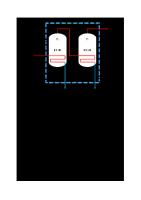
22 STANDERD AEP TYPE CONDENSER:
A = Chanel & removable cover E = One shell pass P = outside packed floating head TEMA standards important parameters for AEP type: Definition Corrosion allowance
Generally for petroleum and related processing application. 1/8 inch
Tube diameters
¾, 1, 1 ¼ ,1 ½ & 2 inch OD
Tube pitch
1.25 inch
Minimum shell diameter
8 inch tabulated
Longitudinal baffle thickness Minimum tie rod diameter
¼ inch minimum
Floating head cover
1.3 times tube flow area
3/8 inch
Significant feature: One tube sheet “floats “in shell or with shell, tube bundle may or may not be removable from shell, but back cover can be removed to expose tube ends.
23 Area of application: High temperature differentials, above about 200°F.extremes; dirty fluids requiring cleaning of inside as well as outside of shell, horizontal or vertical . Limitations: Internal gaskets offer danger of leaking. Corrosiveness of fluids on shell side floating parts. Usually confined to horizontal units. Maintenance: Provision for differential expansion
floating head
Removable bundle
yes
Replacement bundle possible
yes
Individual tubes replaceable
yes
Tube interiors cleanable
yes, mechanically or chemically
Tube exteriors with triangular pitch cleanable Tube exteriors with square pitch cleanable
chemically only yes, mechanically or chemically
Number of tube passes
normally no limitations
Internal gaskets eliminated
yes
*(ref : Rules of Thumb for Chemical Engineers (3rd Ed) by Carl R. Branan)