![AAD03011DK Panasonic [PDF]](https://pdfs.asia/img/200x200/aad03011dk-panasonic.jpg)
15 0 22 MB
Inverter
AAD03010 Instruction Manual
Read this manual carefully before attempting to operate the inverter and store it for further reference.
Panasonic Electric Works Automation Controls(Shanghai) Co.,Ltd.
Foreword Thank you for purchasing the AAD03010 inverter produced by Shanghai Matsushita Electric Works Automatic Control Co., Ltd. This manual introduces the usage and precautions. Read the manual carefully before using the product.
Safety Precautions Read this manual and related documents before attempting to install, operate, service or inspect the inverter. Make sure that you have an understanding of the device, the safety information and all precautions before starting use. Precautions prescribed in this manual is divided into two grades: Caution and Note.
! Caution
The dangerous situations that could lead to personal injury or death by mishandling the equipment.
! Note
The dangerous situations that could lead to moderate or slight personal injury or property damage by mishandling the equipment.
In addition, the precautions prescribed in Caution may lead to serious situations in different conditions. Please follow the information and instructions as laid out in this manual carefully to avoid damage to equipment or risk to personal injury.
1
1. Installation ! Note Install the unit on a non-combustible material such as metal. Installing it on other material could lead to fires. Do not place the unit near flammable materials. Doing so could lead to fires. Do not hold by terminal cover during transportation. Doing so could cause the unit to drop and lead to injuries. Do not allow foreign matter such as metal swarf enter the unit. Entry of this type of matter could lead to fires. Install the unit according to the instruction manual on a place where the weight can be withstood. Failure to do so could lead to dropping of the unit and to injuries. Do not install or operate an inverter that is damaged or missing parts. Doing so could lead to injuries.
2. Wiring ! Caution Always confirm that the input power is OFF before starting wiring. Wait at least five minutes after turning the input power OFF before starting use. Failure to do so could lead to electric shocks or injuries. Always connect the earth. Failure to do so could lead to electric shocks or fires. Wiring work must be carried out by a qualified technician. Failure to do so could lead to electric shocks or fires. Always install the unit before wiring. Failure to do so could lead to electric shocks or injuries.
2
!
Note
Do not connect an AC power supply to the output terminals (U, V, W). Doing so could lead to injuries or fire. Connect the correct wiring for the motor. If the wiring is incorrect, the door control cannot operate properly. Failure to do so could lead to injuries. Connect the control terminals correctly. If the wiring is incorrect, the door control cannot operate properly. Failure to do so could lead to injuries. Confirm that the product's rated voltage and the AC power supply voltage match. Failure to do so could lead to injuries or fire. Tighten the terminal screws with the designated tool. Failure to do so could lead to fire.
3. Operation !
Caution
Always close the terminal cover before turning the input power ON. Do not open the terminal cover while the power is ON. Doing so could lead to electric shock. Do not operate the buttons with wet hands. Doing so could lead to electric shock. Do not touch the inverter terminals when the inverter power is ON or even when the inverter is stopped. Doing so could lead to electric shock. The STOP button is not designed for emergency stop purposes. Prepare a separate emergency stop switches. Failure to do so could lead to injury.
3
Always confirm the security and function operation of the elevator before obstacle detection function is applied. Failure to do so could lead to injury. Make sure to input safety sensor in the main controller of the elevator and to operate the door's obstacle detection on the main controller side. Obstacle detection function of the inverter does not operate in CLOSE arrival area. Always take dual security measures. Failure to do so could lead to injury. Make sure to input arrival signal (limit switch etc.)in the main controller of the elevator and to operate the door's obstacle detection on the main controller side. Do not operate obstacle detection of the door only with OPEN/ CLOSE arrival signal (input signal and the relay's output signal). Failure to do so could lead to injury. Depending on different settings of the fault OPEN operation forced operation time and the stop selection of OPEN/CLOSE operation, sometimes even OPEN/ CLOSE signal are both turned OFF, the door does not stop. Confirm the elevator's security and function operation before using this equipment. (Secure personal safety before carrying out the operation.) Failure to do so could lead to injury. Depending on settings of the start mode and ride-through function settings, if the run signal is ON or the power is restored after a power failure, the inverter may start (restart) suddenly. Keep out of the working part of the motor and the machine. Design the machine so that personal safety can be ensured even if the inverter starts suddenly. Failure to so could lead to injury. Depending on the start mode function setting, if "the fault trip is reset" or "the stop state is released with the panel STOP function" or "door width measurement is reset" when the run signal is input, the inverter may restart suddenly. (Secure personal safety before using this function.) Failure to do so could lead to injury. When the retry function is used, the inverter may automatically start(restart) suddenly. Keep out of the working part of the motor and the machine. (Secure personal safety before using this function.) Failure to so could lead to injury.
〔
〕
4
!
Note
The heat sink fins and brake resistor can reach high temperatures, so do not touch them. Doing so could lead to burns.。 The inverter can be easily set to run from low speeds to high speeds. Confirm the tolerable range of the motor and machine before starting operation. Failure to do so could lead to injure. Prepare holding brakes if required. Failure to do so could lead to injure. If there is no arrival signal, start operation before ensuring the security and function operation of the elevator system. (Secure personal safety before starting operation.) Failure to do so could lead to injury. When carrying out the door repeat control and the door width measurement, the operation direction of the door may change automatically. Start operation after ensuring personal safety. Failure to do so could lead to injury. Adjust and confirm each parameter before operating. Depending on the settings of the parameters, the inverter may work unexpectedly. Failure to do so could lead to injure.
4. Maintenance, Inspection and Part Replacement !
Caution
Wait at least five minutes after turning the input power OFF before starting inspections. Failure to do so could lead to electric shock. Maintenance, inspection and part replacement must be done by qualified persons. [Remove all metal personal belongings (watches, bracelets, etc.) before starting the work. ] (Use tools treated with insulation.) Failure to do so could lead to electric shocks or injury.
5
!
Note
Have an electrician periodically tighten the terminal screws. Loosening of the terminal screws could lead to overheating or fire.
5. Others ! Caution Do not use the inverter for a load other than a three-phase induction motor. Never disassemble or modify the inverter. Doing so could lead to electric shock or injury.
6. General Precautions All diagrams in this instruction manual show the state with the cover or safety partitions removed to explain the details. Before operating the product, replace the covers and partitions to the positions specified, and operate the unit according to the instruction manual.
7. Warning Lable on Inverter [Inverter Surface]
! WARNING ● ELECTEIC SHOCK RISK;
Disconnect supply and wait 5 minutes before working on this equipment.
200V 0.4kW 6
Table of Contents
7
Points for Handling
《Page》 8
Special Precautions
9・10
Installation
11
Outline Dimensions
12
Parts Identification
13∼15
Wiring (Main Circuit)
16・17
Wiring( Control Circuit)
18∼22
Operation( Basic Operation)
23∼28
Function of each modes
29∼32
Setting and Changing Function
33・34
Functional Descriptions (Parameter Table)
35∼39
Functional Descriptions (By parameters)
40∼71
Supplementary Explanation of Door Width Measurement Supplementary Explanation of Obstacle Detection Function of the Door Supplementary Explanation of Communication Function Individual Details and Remedies for Fault Trips Resetting Fault Trips
72
Troubleshooting ①
86
Troubleshooting ②
87
Maintenance and Inspection
88・89
Specifications
90∼92
Warranty
93
73 74∼83 84・85 85
Points for Handling Follow this manual and precautions when handling the inverter. Incorrect handling could lead to inhibited operation or a drop operating life. In the worst case, the inverter could be damaged. Power supply
Use within + 10%, -15% of the tolerable input voltage range, and within ±5% of the tolerable input frequency range.
Circuit breaker (MCCB)
Size a breaker from the selection table on page 17.
Magnet contactor (MC)
N・F
A magnet contactor is not required in normal use. If installed, do not start or stop the inverter with the magnet contactor.
Power factor improvement reactor
Connect this when the power factor must be improved.
Input noise filter
Connect this when noise to the peripheral devices is a problem.
Inverter
Thermal relay for open phase protection
Motor
The ambient temperature is the most important factor for the installation site. Make sure that the tolerable value is not exceeded. (See page 9 and 11) The thermal component built into the inverter is used to protect against overloads. Use an open phase protection thermal relay for open phase protection.
3-phase induction motor.
8
Special Precautions ◆ Use the inverter only within tolerable ambient temperature range.(-10℃ to 50℃) Because the life of the inverter is greatly affected by ambient temperature, use it within tolerable temperature range. Also, pay attention to the installation directions and conditions. (See page 11) ◆ The inverter will be damaged if the power voltage is applied to its output terminal. Applying power voltage to the output terminal U, V or W will damage the inverter. Check carefully for fault wiring and operation procedure. ◆ Never apply a power voltage that exceeds the tolerable voltage of the inverter. ◆ Never touch the inside of the inverter during operation. This is extremely dangerous the inverter contains high-voltage circuit. Be sure to wait at least 5 minutes after the inverter power has been turned OFF, before making an internal check. Do not touch the heat sink fins or brake resistor during operation as these parts will become hot during operation. ◆ Radio interference The main circuit of the inverter contains a higher harmonic component and may interfere with communications equipment such as AM radios if these are used nearby. The amount of radio interference depends on the field strength in the area where the inverter is used. While it is difficult to completely eliminate radio interference, it may be reduced by changing the angle of your radio antenna, using a noise filter with the inverter, housing the inverter in a metallic shield box, or routing inverter cables in metal conduit. ( Please inquire separately.) ◆ Do not attempt insulation testing between the inverter cables. To measure the insulation resistance of the power supply cables or the motor cables, disconnect the inverter connecting wiries and test them with electric connecting wires. Never conduct insulation testing on the control circuits by megohm meter. However, insulation testing can be performed between the charging unit and the ground. ◆ If a magnetic contactor is connected to the power supply side or the load side of the inverter, never use it to start or stop the motor (door controller). Switching the inverter on the power supply side ON and OFF frequently by a magnetic contactor, can cause the inverter to malfunction. Do not turn the inverter on the load side ON and OFF during operation as this causes inverter fault trips. Start or stop the motor only by means of inverter run signal. ◆ Do not connect a power factor capacitor or suppressor to the output terminal of the inverter. Such devices can damage the inverter, its capacitors and other parts. Remove the device if one is connected. ◆ Do not use the inverter for loads other than a three-phase induction motor.
9
◆ Precautions regarding Inverter's Protection Function Various protection functions such as stall prevention, current limit, overcurrent shut-off are built in the inverter. These protection functions are used to protect the inverter from the sudden abnormal conditions in use, so they are not the control functions to be always used. Therefore, do not use the applications in which those protection functions activate in the normal operating conditions. In some cases, the inverter's life may be shorten, or the inverter may be damaged. Always measure the output current, etc. with a measuring instrument, and check the details of the fault trip memory, and confirm that there is no problem in the conditions for all the precautions and specifications describled in the manual when using the inverter.
10
Installation !
Note
Install the unit on a non-combustible material such as metal. Installing it on other material could lead to fire. Do not place the unit near flammable materials. Failure to do so could lead to fire. Do not hold the terminal cover during transportation. Failure to do so could cause the unit to drop and lead to injuries. Do not allow foreign matter such as metal swarf enter the unit. Entry of this type of matter could lead to fire. Mount the unit according to the instruction manual in a place where the weight can be withstood. Failure to do so could lead to dropping of the unit and to injuries. Do not install or operate an inverter that is damaged or with parts missing. Failure to do so could lead to injury. [Install the inverter vertically] [Avoid installing the inverter in the following locations] Installing the inverter in any other way decreases its heat dissipation effect and results in malfunction.
Vertical
Horizontal
Sideways
[Make sure the ambient temperature stays within the specifications] The ambient temperature surrounding the inverter will increase when it is installed near a heating unit or housed inside a panel. This may reduce the life of the inverter. If you want to house the inverter inside a panel, give careful consideration to the cooling method and panel size. Tolerable ambient temperature: -10℃ to 50℃ (Ambient temperatures should be measured at a point 5cm from the inverter.)
11
・Areas subject to direct sunlight. ・Areas subject to water or high levels of humidity. ・Areas with large amounts of oil mist, dust or fiber dust. ・Areas where rain water, water drops or oil drops may come in contact. ・Areas where corrosive gases, explosive gases or flammable gases are present. ・Installation onto flammable materials such as wood, or near flammable materials. ・Areas subject to vibration. Space around the inverter 10cm or more 5cm or more
Inverter 10cm or more
5cm or more
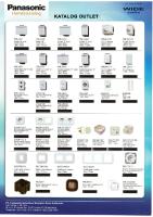
Outline Dimensions Unit: mm
5
126
130
121
2−φ5 ( Mounting holes)
90 100
12
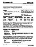
Parts Identification Mounting hole
Frame
Operation panel Communication terminal cover
Warning label
Terminal cover
Control wire lead-in hole
Main circuit wire lead-in hole
Rating nameplate *Check the rating nameplate to confirm that the ordered product has been delivered.
Heat sink fins Brake resistor
Mounting hole
Note) The brake resistor is built into the inverter with brakes only. (Built into the heat sink fin section.)
[Accessory] Communication terminal block (1 pc) Note) Turn off the power supply and remove the communication terminal cover before installing/ removing the communication terminal block. When the communication function is not used, the communication terminal cover should be fitted.
[Details on model] Input power Applicable motor supply capacity (KW) Single-phase 200V
13
0.4
Model With brakes
Without brakes
AAD03010G
AAD03010D
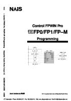
Explanation of Inside of Terminal Cover
Communication circuit terminal block (RS485 communication) Control circuit terminal block (Relay output)
Control circuit terminal block (Input and output signal)
Earth terminal Mounting hole
Brake resistor connecting terminal block
Note) This explanatory drawing shows the state with the terminal cover removed. During normal use, do not remove the terminal cover. Main circuit terminal block
Opening and Closing Terminal Cover
①
① ②
① Opening the terminal cover Lightly push up the cover bottom edge of the terminal cover. ② Closing the terminal cover Lightly push down the center top edge of the terminal cover. Note) After closing the terminal cover, confirm that it is securely closed.
14
Explanation of Operation Panel ▲(UP) button
・
Main display
Hz
MODE button
MODE
▲
RUN
RUN button
SET button
SET
▼
STOP
STOP button
▼(DOWN) button
Main display
The output frequency, output current, line speed, control status monitor, data for function setting and parameter No. are displayed.
RUN button
The switch is used to start the inverter.
STOP button
The switch is used to stop the inverter.
MODE button
This switch is used to change to each "output frequency, output current display", "frequency setting, control status monitor", "rotation direction setting", "function setting" mode, and to switch the display from the data to mode display.
SET button
The switch is used to change the display between the mode and data display, and to save the data. In the "Output frequency, output current display mode", this switch changes the display between the frequency and current.
This switch is used to change the data or output frequency, and to set forward run direction when carrying out forward rotation with the operation panel. This switch is used to change the data or output frequency, ▼(DOWN) button and to set reverse run direction when carrying out reverse rotation with the operation panel.
▲(UP) button
Handling for the displays of output current, output voltage and internal DC voltage. 1)The displayed output current, output voltage and internal DC voltage are not intended for precise measurement. Use this only as a guide value. (Use a separate measuring instrument when precise values are required.) 2)Especially for the displayed output current, a relatively large value may be displayed at approx.40% or less of the rated current. (For example, even if there is no output current, a certain level may be displayed. Note that when the inverter is stopped, "0.0A" will be displayed.)
15
Wiring (Main Circuit) ! Caution Always confirm that the input power is OFF before starting wiring. Wait at least five minutes after turning the input power OFF before starting wiring. Failure to do so could lead to electric shocks, fires or injuries. Always connect the earth. Failure to do so could lead to electric shocks, fires or injuries. Wiring work must be carried out by a qualified technician. Failure to do so could lead to electric shocks, fires or injuries. Always install the unit before wiring. Failure to do so could lead to electric shocks or injuries.
! Note Do not connect an AC power supply to the output terminals (U, V, W). Doing so could lead to injuries or fire. Connect the correct wiring for the motor. If the wiring is incorrect, the door control cannot operate properly. Wrong connection could lead to injuries or fires. Confirm that the product's rated voltage and the AC power supply voltage match. Failure to do so could lead to injuries or fire. Tighten the terminal screws with the designated tightening tool. Failure to do so could lead to fire.
■ Precautions on wiring Note the following points carefully to prevent miswiring and misuse of the inverter. (Devices may be broken.) 1)Connect the power supply to input terminals (L, N) and the motor to output terminals (U,V,W). 2)Use sleeved round crimp terminals for power supply and motor terminals. 3)After wiring the main circuit, double check for tightness as access will be limited once control circuit wiring is in place. 4)When connecting directly to a large capacity power transformer (500kVA or more), always install a power factor improvement reactor on the inverter's input side. 5)Select connected devices and wire size according to the table on page 17. 6)Class D(3) grounding must be done.
16
■ Wiring (Main Circuit Terminal) Ground marking 《 Screw size》 Brake resistor
Power supply
Main circuit terminal: M4 Brake resistor connection Ground terminal terminal
Circuit breaker (MCCB)
Grounding terminal: M4 Main circuit terminals L
N
U
V
W
Class D(3) grounding IM
Motor
Note) Always connect protective devices such as fuse for overcurrent, short circuits and leakage protection to the input terminal.
■ Connected Device, Wire Size and Main Circuit Terminal Tightening Torque Inverter capacity Circuit breaker Tightening torque 0.4 kW
BC−30N 10A
1.2 N・ m
Wire size 2 mm 2 { 14AWG }
Note1) If the breaker's overcurrent trip is a magnetic type, the device could overheat due to higher harmonics. Use a load rate of 50% or less in this case. Note2) When using an installed circuit breaker with motor protection, remove it.
■ Precautions for Using Regenerative Brakes 1)When using the regenerative brake, select the one with brakes. The brake resistor is built in the inverter. (It is built in the radiation fin.) 2)When using regenerative brakes, set the parameter P17 data to"0". The brakes will not activate when the factory setting "1" is set. 3)The regenerative brake specifications are shown below. Carefully consider the working conditions before using these brakes. Note that the inverter could be damaged if the specifications are exceeded. ・Maximum duty factor (%ED): 2% ・Maximum working time: 3s ・Maximum torque: 100%
17
Control Circuit Wiring ■ Wiring (Control Circuit Terminal) (Common)
(Common)
− Built-in power supply
Phase B signal
Built-in power supply
Input signal
Phase A signal
+
Open speed change signal Close speed change signal
Safety sensor
Close arrival signal
Open arrival signal
Close signal
Open signal
①②③ ④ ⑤ ⑥⑦ ⑧ ⑨⑩ ⑪ ⑫
Encoder signal
◆ Built-in power supply specification: 12 V DC -10%/ +20%, 0.1A or less Note1) Do not use the Built-in power supply for other devices except for the encoder power supply. The inverter could be damaged if the Built-in power supply is connected incorrectly. Note2) The NPN open collector output should be used for the output signals (phase A and phase B) of the encoder. Please read the precautions on the encoder. (See page 21 and page 22) Note3) The common terminals(⑧and⑫) are connected within the inverter. Do not ground the common terminal.
■ Wiring (Output terminals)
C1
B1
A1
C2
B2
A2
C3
B3
A3
COM NC NO COM NC NO COM NC NO
Relay 1 output
Relay 2 output
Relay 3 output
◆ Relay output contact specifications: 1c no-voltage contact, 230 V AC 0.3 A, 30 V DC 0.3 A(resistance load) Mechanical lifetime: 100 million times or more(switching frequency: 180 times/min.) Electrical lifetime: 100 thousand times or more(switching frequency at rated control capacity: 20 times/min.)
18
■ Wiring ( Communication Terminals) ◆ Terminals to connect personal computers and PLCs by the RS485 communication. Terminator
RS485
D+
D+
D+
D−
D−
D−
D+
D+
D+
D−
D−
D−
E
E
E
V+
V+
V+
V−
V−
V−
D + : Transmission line + terminal (RS485 communication) D − : Transmission line - terminal (RS485 communication) E : Terminator terminal (RS485 communication)
* Related parameter No. P35 to P40. * Connect the D+ side and D+ side, and D- side and D- side of the communication terminals. Short D- side and E side of the inverter to circuit * The be a terminator should be shorted. Do not short the units other than the terminator. * Do not use the V+ and V- terminals. Always leave them open. If they are connected incorrectly, the inverter could be damaged.
Transition connecting wire: Max. 500m
■ Electric Cable Size and Control Circuit Terminal Tightening Torque Terminal mark
Screw size
Tightening torque N・m
① ∼⑫
M2
0.22∼ 0.25
M3
0.5∼ 0.6
M2
0.22∼ 0.25
A1 -3,B1 -3 C1- 3 D+, D−, E V+, V−
Wire's insulation removing size
Cable size 0.25∼ 0.75 mm 2 (AWG24∼AWG18) 0.25∼ 0.75 mm 2 (AWG24∼AWG18) 0.25∼ 0.75 mm 2 (AWG24∼AWG18)
・Screwdriver: Small-size Θscrewdriver (Depth of the edge: 0.4mm/ Width of the edge: 2.5mm)
5mm 6mm 7mm
・ Wire's insulation removing size
[Wiring Method] ・For the wiring of the control circuit terminals, use the electric wires after removing the specific size of wire's insulation. ・ Loosening the interminal screws and insert the cables from under the terminal block, and tighten the screws with a specific torque. Note1) Twist the strands of the uncovered electric wires. Do not solder them. Note2) Tightening loosely causes the wires to be come away or malfunctions. Tightening too hard causes the short-circuit or malfunctions caused by the damage to the screw or the inverter.
19
■ Explanation of Control Circuit Terminals Terminal No.
Related Parameter No.
②
Terminal Function Input terminal of Open Signal (forward run operation) Input terminal of Close Signal (reverse run operation)
③
Input terminal of Open arrival signal
④
Input terminal of Close arrival signal
⑤
Input terminal of safety sensor
P43,P44
⑥
Input terminal of Open speed change signal
P09,P43,d48
⑦
Input terminal of Close speed change signal
P09,P43,d50
⑧
Common terminal of input signal 1 to 7
―
⑨
Built-in power supply (+) terminal (12 V DC)
―
⑩
Input terminal of encoder (phase A) signal
P09,P46,P52
⑪
Input terminal of encoder (phase B) signal
P09,P46,P52
⑫
Built-in power supply (-) terminal (12 V DC common terminal)
―
①
P08 P08 P43,P45,P47,P76, d49 P43,P45,P47,P76, d47
A1
Relay 1 contact output terminal (NO: at factory setting) P48
B1 C1 A2 B2 C2 A3
Relay 1 contact output terminal (NC: at factory setting)
P48
Relay 1 contact output terminal (COM)
P48
B3
Relay 3 contact output terminal (NC: at factory setting)
P50
C3
Relay 3 contact output terminal (COM)
P50
D+
Transmission line + terminal (RS485 serial communication signal)
P35 to P40
D−
Transmission line - terminal (RS485 serial communication signal)
P35 to P40
E
Terminal for setting terminator (Transmission line- terminal and short-circuit) ― Do not short the units other than the terminator.
V+ V−
Relay 2 contact output terminal (NO: at factory setting) P49 Relay 2 contact output terminal (NC: at factory setting)
P49
Relay 2 contact output terminal (COM)
P49
Relay 3 contact output terminal (NO: at factory setting) P50
Unused terminal Unused terminal
― ―
20
■ Precautions on Wiring 1. Use shielded wires for all control signal wires and keep them away more than 20cm from power lines and strong electric circuits. 2. The wiring length of the control signal wire is 30m or less. 3. The control circuit's input signal is a minute signal, so use two minute signal contacts in parallel or use a twin contact to prevent contact faults when inputting the contact. 4. No-voltage contact signal or open-collector signal should be used with control terminals No. 1 to 7. (If a voltage is applied across these terminals, the inverter may be damaged.) * Input circuit specifications are shown in Fig. 1. Take special care to avoid loop or leakage current. 5. Precautions on encoder (Refer to Fig.2 and 3) Note1) NPN open-collector output is used with ouput signal (Phase A, Phase B) of the encoder. Use the transistor that meets the specifications below. ・ Max. rated voltage : 30VDC or more ・ Rated current : 20mA or more Note 2) Power supply of the encoder should be 12 V DC -10%/ +20%. Note 3) Consumption current of the encoder should be 50mA or less. Leghth of wiring Max. 5m Inverter internal circuit
Inverter internal circuit 12V DC
Terminals No.9
2k Ω 12V DC 2k Ω
Terminals No.10, 11
Terminals No. 1 to 7 Terminals No. 8
Terminals No.12
Fig. 1 Common
Fig. 2
21
Encoder VCC
Output(Phase A, Phase B)
Note4) Control the cable wiring length of the encoder within 5m or less. Note5) The max. input pulse frequency and the min. input pulse width should be used at the following setting. ・ Max. input pulse frequency (1/T) : 10 kHz or less ・ Phase difference (t1): 25μs or more ・ Overlap (t2) : 25μs or more
T Phase A Phase B
t1
t2
t1
t2
Fig. 3 Note6) Confirm the rotation direction before making the connection of the output signal (phase A and phase B) of the encoder. [Judging the pulse signals of phase A and B, and forward/ reverse directions] Open operation in Phase A forward direction (Count addition)
Phase B Close operation in Phase A reverse direction (Count subtraction)
Phase B
6. For the communication cable, use a double-core cable(VCTF) or twisted pair cable ( with shield). Keep the cable away from power lines and strong electric circuits. 7. The total length of the communication cable must be 500m or less.
22
Operation (Basic Operation) !
Caution Always close the terminal cover before turning the input power ON. Do not open the terminal cover while the power is ON. Failure to do so could lead to electric shock. Do not operate the buttons with wet hands. Failure to do so could lead to electric shock. Do not touch the inverter terminals when the inverter power is ON or even when the inverter is stopped. Failure to do so could lead to electric shock. The STOP button is not designed for emergency stop purposes. Prepare a separate emergency stop switch. Failure to do so could lead to electric shock. Always confirm the security and function operation of the elevator system before obstacle detection function is applied. Failure to do so could lead to injury. Make sure to input safety sensor in the main controller of the elevator and to operate the door's obstacle detection on the main controller side. Obstacle detection function of the inverter does not operate in the CLOSE arrival area. Always take dual security measures. Failure to do so could lead to injury. Make sure to input arrival signal (limit switch etc.) in the main controller of the lift and to operate the door's obstacle detection on the main controller side. Do not operate obstacle detection of the door only with OPEN/CLOSE arrival signal (input signal and the relay's output signal). Failure to do so could lead to injury. Depending on different settings of the fault OPEN operation forced operation time and the stop selection of OPEN/CLOSE operation, sometimes even OPEN/ CLOSE signal are both turned OFF, the door does not stop. Confirm the lift's security and function operation before using this equipment. (Secure personal safety before carrying out the operation.) Failure to do so could lead to injury. Due to setting of the start mode and the ride-through restart function, when the run signal is ON, the inverter may start (restart) suddenly if the power is applied or the power is restored after a power failure. Keep out of the working part of the motor and the machine. Design the machine so that personal safety can be ensured even if the inverter starts suddenly. Failure to so could lead to injury.
〔
23
〕
Depending on the start mode function setting, if "the fault trip is reset" or "the stop state is released with the panel STOP function" or "door width measurement is reset" when the run signal is input, the inverter may restart suddenly. (Secure personal safety before using this function.) Failure to do so could lead to injury. When the retry function is used, the inverter may automatically start (restart). Keep out of the working part of the motor and the machine. (Secure personal safety before using this function.) Failure to so could lead to injury.
!
Note The heat sink fins and brake resistor can reach high temperatures, so do not touch them. Doing so could lead to burns. The inverter can be easily set to run from low speeds to high speeds. Confirm the tolerable range of the motor and machine before starting operation. Failure to do so could lead to injure. Prepare holding brakes if required. Failure to do so could lead to injure. If there is no arrival signal, start operation before ensuring the security and function operation of the lift system. (Secure personal safety before starting operation.) Failure to do so could lead to injury. When carrying out the door repeat control and the door width measurement, the operation direction of the door may change automatically. Start operation after ensuring personal safety. Failure to do so could lead to injury. Adjust and confirm each parameter before operating. Depending on the settings of the parameters, the inverter may work unexpectedly. Failure to do so could lead to injure.
Before turning power ON, check the following points again. ① Check that all wiring is correct. Reversed wiring between the power supply and the load, in particular, can result in damage to the inverter. ② Make sure the inverter rating and power supply voltages match each other. ③ Make sure no power factor capacitor is connected to the motor, as it can damage the inverter and the capacitor. ④ Before starting a trial run, check the set frequency.
24
Setting the Frequency and Forward/Reverse Run Function With the Operation Panel There are following methods for setting the frequency and carrying out forward/reverse run function with the operation panel. ・Frequency setting: [Digital setting method] ・Forward/reverse run operation: [Forward run/reverse run method] [Start/stop, rotation direction mode setting method] 1.Setting the frequency 1)Digital setting method (Parameter P09 set to "0") Press the MODE button on the panel to enter the frequency setting mode (Fr). Press the SET button, display the frequency to be set with the▲(up) button and (down) button, and then press the SET button to enter the data. The frequency can be changed by holding down the▲(up) button or (down) button during operation. (Hereafter, this function is called the MOP function.) This MOP function cannot be used when parameter P08 is set to "1".
2.Forward/reverse run function 1)Forward run/reverse run method (Parameter P08 set to "1") Press the▲button (forward run) or button (reverse run) on the panel to select the rotation direction. Operation will start when the RUN button is pressed, and will stop when the STOP button is pressed. *The inverter will not start running just by pressing the RUN button. 2)Sart/stop, rotating direction mode setting method (Parameter P08 set to "0") First, press the MODE button twice to enter the rotation direction setting mode (dr). Press the SET button to display the rotation direction data, change the rotation direction with the▲(up) button and (down) button, and then press the SET button to enter the data. (Forward run is set as the factory setting.) Operation will start when the RUN button is pressed, and will stop when the STOP button is pressed. Note) In the case of the door control, the forward run operation is OPEN operation and the reverse run operation is CLOSE operation.
3.Combination of "Mop function", "rotation direction setting mode" and forward/ reverse run function. Forward/reverse run function Forward run/reverse run method Start/stop, rotation direction mode setting method
MOP function
Details of rotation direction setting mode
(Cannot be used) Only monitor function (Can be used)
Monitor function and direction setting function
Note) When the forward run/reverse run function is set to "forward run/reverse run method (parameter P08=1) ", the MOP function cannot be used.
25
Operating With the Operation Panel -1 (Factory Setting State) ・Forward /reverse run function: Start/stop, rotation direction mode setting (Parameter P08=0) ・Frequency setting: Digital setting (Parameter P09=0) [Example for rotating in forward direction at operating frequency 5Hz] Main display Power ON
The main display lamp will turn ON.
MODE
Run command
Press the MODE button.
0
0
F
r
Press the SET button. (The main display will flicker.)
0
0. 5
0
5. 0
▼
Press the▲(up) or (down) buttons to display 5Hz on the main display. (The main display will flicker.)
SET
Press the SET button to set the data.
0
0
RUN
Press the RUN button. As the factory setting is the forward operation, the motor will start rotating in the forward direction and operate at 5Hz.
0
5. 0
SET Frequency setting
0
▲
0
[Example for rotating in forward direction at operating frequency 10Hz] MODE Changing the frequency during operation
SET ▲ ▼ SET
F
Press the MODE button.
r
Press the SET button. (The main display will flicker.)
0
5. 0
Press the▲(up) or (down) buttons to display 10Hz on the main display. (The main display will flicker.)
1
0. 0
1
0. 0
0
0
Press the SET button to set the data. The display will change to the output frequency, and will reach 10Hz.
[Stopping operation] Stop command
STOP
Press the STOP button. The motor will start to decelerate and will stop.
0
[Changing the frequency with the▲and buttons during operation (MOP function)] The operating frequency can be changed with the▲and buttons during operation. ・ If the▲(up) button is held down, the operating frequency will increase. ・ If the (down) button is held down, the operating frequency will decrease. Note ) Once the operating frequency is determined, press the MODE button and then press the SET button twice to set the operating frequency. If this is not carried out, this frequency will not be saved when the power is turned OFF.
26
[Continued from previous page, Example for rotating in reverse direction at operating frequency 10Hz] Main display
Changing the rotation direction
Run command
MODE
Press the MODE button.
F
r
MODE
Press the MODE button.
d
r
SET
Press the SET button. (The main display will flicker.)
L −
F
▲
Press the▲(up) button. (The main display will flicker.)
L −
r
SET
Press the SET button to set the data.
0
0
0
RUN
Press the RUN button. As the frequency is already set to 10Hz, the motor will start rotating in the reverse direction and operate at 10Hz.
1
0. 0
[Example to change to forward rotation during reverse rotation]
Changing the rotation direction
MODE
Press the MODE button.
F
r
MODE
Press the MODE button.
d
r
Press the SET button. (The main display will flicker.) Press the▼(down) button. (The main display will flicker.)
L −
r
L −
F
Press the SET button. Reverse The motor will decelerate, and will start forward rotation at 10Hz.
1
Forward
1
0. 0
0
0
SET ▼ SET
[Stopping operation] Stop command
27
STOP
Press the STOP button. The motor will start to decelerate and will stop.
0. 0 0. 0
0
Operating With the Operation Panel -2 ・Forward / reverse run function: Forward run/reverse run operation (Parameter P08=1) ・Frequency setting: Digital setting (Parameter P09=0) [Example for rotating in forward direction at operating frequency 5Hz] Main display Power ON
The main display lamp will turn ON.
MODE
Forward run setting
Press the MODE button.
0
0
F
r
Press the SET button. (The main display will flicker.)
0
0. 5
0
5. 0
▼
Press the ▲(up) and▼(down) buttons to display 5Hz on the main display. (The main display will flicker.)
SET
Press the SET button to set the data.
0
0
0
▲
Press the▲(up) button, and set the rotation direction to forward run. (Press the▼button to set reverse run.)
0 −
F
SET Frequency setting
0
▲
・Current state (0: Stop, F: Forward run, r: Reverse run) ・Set rotation direction (F: Forward run, r: Reverse run) Press the RUN button. Run command RUN The motor will start rotating in the forward direction and operate at 5Hz.
5. 0
[Example to change from forward run to reverse run during operation] Reverse run setting
▼
Press the▼(down) button, and set the rotation direction to reverse run.
F −
r
・Current state (F: Forward run) ・Set rotation direction (r: Reverse run) Run command
RUN
Forward Press the RUN button. The motor will gradually decelerate, and will start forward rotation at 5Hz again. Reverse
[Stopping operation]
5. 0 0. 0 5. 0
Press the STOP button. 0 0 0 The motor will start to decelerate and will stop. Note) If the RUN button is pressed after setting the rotation direction, the rotation direction will not changed.
Stop command
STOP
[Canceling the rotation direction setting] After setting with the▲and▼buttons, the rotation direction can be canceled by pressing the same button again.
28
Function of each modes The inverter has the following five modes. ① Output frequency・current display mode, ② Frequency setting・monitor mode, ③ Rotation direction setting mode, ④ Control state monitor mode, ⑤ Function setting mode Normally, use in the output frequency・current display mode. This mode is entered when the voltage is applied.
①Output frequency・current ・ display mode
SET
[Output frequency display] 1.Output frequency 2.Operation preparation (line speed) status display
1 0. 0
Output current display mode The output current of the inverter is displayed.
SET
0. 0 A
0 0 0
MODE
SET
②Frequency setting・monitor mode The frequency can be digital set ,and the parameter P09 frequency command can be monitored.
[Data change and monitor]
SET
・ Change the frequency with the ▲and buttons, and press the SET button to set the data. ・ The parameter P09 command frequency is displayed except during the digital setting.
MODE
F r
[Mode display]
MODE
SET
③Rotation direction setting mode The rotation direction can be set and the control status(local/external/ communication) can be monitored with panel operations.
[Mode display]
[Data change]
SET MODE
d r
MODE ④Control state monitor mode The control state and errors are monitored in this mode. The monitor No. is displayed when this mode is entered. Set the required No. with the▲ and buttons.
[Monitor No. display]
MODE [Continued to next page]
29
n 0 1
Change the data with the▲and buttons, and press the SET button to set the data.
L− F
L − r
Local : L External : E
Local Local Forward run Reverse run Communication: C Note) When the parameter P08 is set to the data other than "0", the settings cannot be changed only with the monitor.
SET
[Monitor]
SET
The monitor data is displayed by pressing the SET button. (The next monitor No. will appear when the SET button is pressed.)
MODE
The current monitor No. will appear when the MODE button is pressed.
[Continued from previous page]
⑤Function setting mode
[Data change]
The parameter data can be changed and monitored in this mode. The parameter No. is displayed when this mode is entered. Set the required No. with the▲and buttons. A password can be set in the mode.
[Parameter No. display]
P 0 1
[Password display]
P S
SET
The data can be changed with the▲and buttons.
SET
Press the SET button, and set the changed data. (The next parameter No. will appear when the SET button is pressed.)
MODE
The current parameter No. will appear when the MODE button is pressed. (The data cannot be set.)
MODE * For the password settings, the following 2 settings are available: "Parameter P41: Password setting for all regions.'' and "Parameter d53: d-region parameter password setting." Input a password in the parameter d00 to cancel the password for d region parameter.
■ Control State Monitor The following 17 items can be monitored in the control state monitor mode. Monitor No. n 01 n02 n 03 n 04 n 05 n 06 n 07 n 08 n 09 n 10 n 11 n 12 n 13 n 14 n 15 n 16 n 17
Monitor item Output frequency Output current Output voltage Internal DC voltage Setting frequency Detection frequency Door position area Door position OPEN arrival position data No. of door switching Encoder detection status Fault display 1 (latest) Fault display 2 (second to latest) Fault display 3 (third to latest) Fault display 4 (fourth to latest) Control terminal state (input signal) Control terminal state (output signal)
Indication Output frequency(unit: Hz) Output current (unit: A) Output voltage (unit: V AC) Internal DC voltage (unit: V DC) Setting frequency (unit: Hz)
Monitor for door control (Refer to pages 31 and 32)
Details of errors (Refer to pages 84 and 85) Input/output of control circuit terminals (Refer to page 32)
30
● Output current (n02), output voltage (n03), internal DC voltage (n04) ・ The indications of the output current, output voltage and internal DC voltage are not the accurate indications for measuring. Use those indications to get rough values. (If you need the accurate values, use a measuring instrument.)
● Detection frequency (n06) ・ Detects the actual speed of rotation from encoder signals. Displays the value as detection frequency that is calculated to the frequency from a detected speed of rotation. No. of pulses of encoder per minute[p/min] Speed of rotation [r/min] = Encoder constant[p/r] Detection frequency [Hz] =
No. of motor poles 120
×Speed of rotation [r/min]
Note1) The No. of motor poles (Parameter P51) and encoder constant (Parameter P52) should be set. Note2) In the non-encoder mode (Parameter P09= [1, 2, 3]), the detection frequency (n06) cannot be detected. The panel display will be "0.0".
● Door position area (n07) ・ Indicates the operation area of the door position. [0]: CLOSE hold operation area, [1 to 6]: OPEN operation area [7]: OPEN hold operation area, [8 to 13]: CLOSE operation area
● Door position (n08) ・ Indicates the data value of the door position. (Data range: 1 to 65535) Operation panel display: Displays as 1 = "0.01" and 10,000 = "100.". Monitor by communication function: Directly displays the door position data.
● OPEN arrival position data (n09) ・ Indicates the data value of the door position while the OPEN arrival signal is changing from OFF to ON. Operation panel display: Displays as 1 = [0.01] and 10,000 = [100.]. Monitor by communication function: Directly displays the door position data.
● No. of door switching (n10) ・ Number of switching can be monitored up to 65,535 times. Operation panel display: Displays as 1 time = "0.01" and 10,000 times = [100.]. Monitor by communication function: Directly displays the number of switching. ・ The data of the number of switching can be cleared by setting the parameter P42 (setting data clear) to "2".
31
● Encoder detection status (n11) ・ Indicates the pulse frequency of the encoder signal. ・ Also indicates the rotation direction of the motor by the encoder signal. F: Forward run (OPEN operation), r: Reverse run (CLOSE operation) Note) In the non-encoder mode (Parameter P09 = [1, 2, 3]), the encoder detection status (n11) cannot be detected. The panel display will be "0.0".
● Control terminal status (Input signal/output signal) (n16 and n17) ・ The statuses of the input and output signals of the control circuit terminal can be monitored by "Lightening/Lightening out of each LED segment".
n16: Input signal Lights: Closed between the input terminal and the common terminal. Lights out: Opened between the input terminal and the common terminal. Note) The input signal monitor lights when the input terminal is closed and lights out when the input terminal is opened. It is independent of the input signal logic setting.
n17: Output signal Lights: When the relay coil is energized. Lights out: When the relay coil is not energized. LED position
Input signal n16
Output signal n17
①
OPEN signal
Relay 1 output signal
②
CLOSE signal
Relay 2 output signal
③
OPEN arrival signal
Relay 3 output signal
④
CLOSE arrival signal
⑤
Safety sensor signal
⑥
OPEN speed change signal
⑦
CLOSE speed change signal
⑧
Encoder phase A signal
⑨
Encoder phase B signal
⑥
⑤ ④
③ ②
⑨
⑧
⑦
①
32
Setting and Changing Function Various function data can be changed and set when the operation is stopped. Note that some functions can be changed during operation.(See page 34)
Setting functions when operation is stopped. [Setting example: Change the maximum frequency from 50Hz to 60Hz.] (Changing the parameter P03 data from "50" to "60".)
Main display
0
0
Press the MODE button
F
r
MODE
Press the MODE button
d
r
MODE
Press the MODE button
n
0
1
MODE
Press the MODE button(Enter the function setting mode) (if a password is set, it must be entered at this point. See page 53.) Press the▲(UP) button twice, and change the parameter No. to P03.
P
0
1
P
0
3
STOP
Press the STOP button to stop the inverter
MODE
▲
0
SET
Press the SET button to display the parameter P03 data.(The main display will flicker.)
5
0
▲
Press the ▲(UP)button, and change the data display value to "60". (The main display will flicker.)
6
0
SET
Press the SET button to set the data.
P
0
4
MODE
Press the MODE button to make the status ready for operation.
0
0
0
OPERATION PREPARATION …The normal stop state will be entered and COMPLETED the inverter can be run.
[Setting Precautions] 1.After the function is set, the inverter will not run unless the MODE button is pressed and the "operation preparation completed" state is returned to. 2.If the function setting returns to the "operation preparation completed" state during data changing, while a start input signal is being applied through external control, an "OP" error will be displayed, causing the inverter to remain inoperative. *Reset the fault indication using the instructions under "Resetting Fault Trips" (page 85). 3.The set data will be stored in the memory even after the power supply has been turned OFF.
33
Setting Function During Operation
! Caution:
The motor and motor load fluctuation could change significantly and the motor may suddenly stop or start when data is being changed during operation. Before making changes, ensure personal safety at all times. Failure to do so could lead to injury.
[Setting example: To change torque boost level from 10(%) to 5(%)] Main display
Control motor with new data
Control motor with current data
Operation state (for 10Hz operation) MODE ▲ SET ▲
▼
SET MODE
Press the MODE button four times, and enter the "function setting mode." Press the ▲(up) button four times, and change the parameter No. to P05. Press the SET button to display the parameter P05 data. (The main display will flicker.) Press the▲(up) and (down) button to set the data display value to "5". (The main display will flicker.) Press the SET button to set the data. Press the MODE button to enter the "output frequency, output current display mode".(The display will not change unless the MODE button is pressed.)
1
0.
0
P
0
1
P
0
5
1
0
0
5
P
0
6
1
0.
0
* If change the data parameters during operation, please see "Parameter Table".
[Setting Precautions] 1. During operation, the parameters other than those that can be changed will show data, but the data cannot be changed. 2. If a stop signal is input while changing the data and the inverter stops, the mode will return to the " operation preparation completed" state. 3. If change the parameters d14 to d27(Open/Close arrival holding frequency and Open/Close frequency 1 to 6) to "000 setting", output of the inverter will enterstop state. (The motor will start or stop simultaneously when theabove-mentioned data are being changed and have been changed, as well as when the data are being set. Carry out the operation after safety is confirmed completely.)
34
Functional Descriptions(Parameter Table) The parameter table consists of "P region parameters: P01 to P79" and ''d region parameters: d00 to d53".
■ P region parameters: P01 to P79 N o.
Factory Setting range setting data
★
P01
1ST ACCELERATION TIME(s)
0・0.1 to 999
0.5
★
P02
1ST DECELERATION TIME(s)
0・0.1 to 999
0.5
P03
V/F PATTERN
50・ 60・ FF
50
P04
V/F CURVE
0・1
0
P05
TORQUE BOOST LEVEL(%)
0 to 40
10
P06
ELECTRONIC THERMAL FUNCTION SELECT
0・1・ 2・3
2
P07
SETTING OF THERMAL CURRENT(A)
0.1 to100
3.6
P08
OPERATION COMMAND SELECT
0 to 3
0
P09
FREQUENCY SETTING SIGNAL
0 to 6
0
P10
STOP MODE
0・1
0
P11
STOP FRENQENCY(Hz)
0.5 to 60
0.5
P12
DC BRAKE TIME(s)
0・0.1 to 120 000
P13
DC BRAKE LEVEL
0 to 100
00
P14
MAX. OUTPUT FREQUENCY (Hz)
50 to 250
50.0
P15
BASE FREQUENCY (Hz)
45 to 250
P16
OVERCURRENT STALL PREVENTION FUNCTION
0・1
50.0 1
P17
OVERVOLTAGE STALL PREVENTION FUNCTION
0・ 1
1
P18
SKIP FREQUENCY 1 (Hz)
0・0.5 to 250 000
P19
SKIP FREQUENCY 2 (Hz)
0・0.5 to 250 000
P20
SKIP FREQUENCY 3 (Hz)
0・0.5 to 250 000
P21
SKIP FREQUENCY BAND WIDTH
0 to10
0
P22
CURRENT LIMIT FUNCTION (s)
0・ 0.1 to 9.9
0
P23
START MODE
0・1・2・ 3
0
P24
RIDE-THROUGH RESTART
0・1・2
0
P25 P26
WAIT TIME (s) RETRY FUNCTION SELECT
0.1 to 100 0・1・ 2・ 3
0.1 0
P27
RETRY TIMES LOWER FREQUENCY CLAMP(Hz) UPPER FREQUENCY CLAMP (Hz)
1 to 10 0.5 to 250
1
P28 P29
★
35
Parameter name
0.5 to 250
0.5 250
Parameter name
No . P30 ★
P31
MONITOR SELECT LINE SPEED MULTIPLIER
P32
MAX. OUTPUT VOLTAGE(V)
P33
OCS LEVEL(%)
P34
CARRIER FREQUENCY(kHz)
P35
COMMUNICATION STATION No. SETTING
P36
COMMUNICATION SPEED
P37
STOP (BIT)
P38
PARITY CHECK
P39
TIMEOVER DETECT(s)
P40
SEND WAIT TIME (ms)
P41
PASSWORD
P42
SETTING DATA CLEAR
P43
INPUT SIGNAL LOGIC SETTING
★
P44
SAFETY SENSOR RESPONSE TIME(ms)
★
P45
ARRIVAL SIGNAL RESPONSE TIME(ms)
P46
ENCODER FAULT DETECT TIME(s)
P47
ARRIVAL SW FAULT DETECT TIME(s)
P48
RY1 FUNCTION SELECT
P49
RY2 FUNCTION SELECT
P50
RY3 FUNCTION SELECT
P51
NO. OF MOTOR POLES
P52
ENCODER CONSTANT
P53
−
P54
−
P55
−
P56
−
P57
−
P58
−
★
P59
OVERLOAD DETECTION FREQUENCY 1 (Hz)
★
P60
OVERLOAD DETECTION FREQUENCY 2 (Hz)
★
P61
OVERLOAD DETECTION CURRENT 1 (A)
★
P62
OVERLOAD DETECTION CURRENT 2 (A)
★
P63
OVERLOAD DETECTION JUDGEMENT TIME (ms)
★
Setting range 0・1 0.1∼100 0 ・ 1∼500 1∼200 0.8∼15.0 1∼31 48・96・192 1・2 0・1・2 0・0.1∼60.0 1∼999 0 ・ 1∼999 0・1・2 0∼31 0 ・ 1∼999 1∼999 0・0.1∼2.0 0・0.1∼10 0∼7・r0∼r7 0∼7・r0∼r7 0∼7・r0∼r7 2・4・6 50∼999 − − − − − − 0 .5∼250 0.5∼250 0.1∼100 0. 1∼100 0・1∼999
Factory setting data 0 3.0 0 140 10 01 96 1 0 000 001 000 0 0 10 10 0 0 7 4 5 4 512 0 1.0 0.0 1.0 0.0 5.0 10.0 50.0 1.2 1.2 10
36
No.
Parameter name
Factory Setting range setting data
★
P64
★
P65
★
P66
OBSTACLE JUDGMENT FREQUENCY 0 ∼100 RATIO (LOW SPEED) (%) OBSTACLE JUDGMENT FREQUENCY 0 ∼100 RATIO (HIGH SPEED) (%) OBSTACLE JUDGMENT CHANGE 0.5∼250 FREQUENCY (Hz)
★
P67
OBSTACLE DETECTION JUDGMENT TIME (ms)
0・1∼999
100
★
P68
START CONFIRMATION TIME (ms)
100∼999
200
0・0.1∼500
0.0
0・0.1∼500
0.0
0.0∼10
0.0
0.0∼10
3.0
0.0∼10
3.0
0・1・2
0
0・1 0・1・2
0 0
0.1∼10
1.0
1∼999
100
0・0.1∼10
0
★
P69
★
P70
★
P71
★
P72
★
P73 P74 P75 P76
★
P77
★
P78
★
P79
FORCED ON OPERATION JUDGMENT TIME (s) FAULT ON OPERATION FORCED OPERATION TIME (s) FAULT ON OPERATION OPEN ARRIVAL HOLD TIME (s) REPEAT OPEN ARRIVAL HOLD TIME (s) REPEAT CLOSE ARRIVAL HOLD TIME (s) S-SHAPED ACCELERATION/ DECELERATION FUNCTION STOP SELECT IN OPEN/CLOSE OPERATION NO ARRIVAL SIGNAL SELECT SLIP ARRIVAL JUDGMENT FREQUENCY (Hz) SLIP ARRIVAL JUDGMENT TIME (ms) SLIP OPEN ARRIVAL SUBSTITUTE SELECT (s)
50.0 70.0 5.0
Note1) The ★ mark indicates parameters that can be changed during the inverter is in operation. Note2) Parameters P53 to 58(Function cannot be used) indicate the data is set in factory and cannot be changed. Note3) For the communication parameters P35 to 40, always turn off the power supply after the data has been set. The set value will be effective after the power supply is turned on again.
37
■ d region parameters : d00 to d53 No. ★ ★ ★ ★ ★ ★ ★ ★ ★ ★ ★ ★ ★ ★ ★ ★ ★ ★ ★ ★ ★ ★ ★ ★ ★ ★ ★ ★ ★ ★ ★ ★ ★
d00 d01 d02 d03 d04 d05 d06 d07 d08 d09 d10 d11 d12 d13 d14 d15 d16 d17 d18 d19 d20 d21 d22 d23 d24 d25 d26 d27 d28 d29 d30 d31 d32
Parameter name d region password input Setting value of door width CLOSE Arrival position(%) OPEN Speed change position 1(%) OPEN Speed change position 2(%) OPEN Speed change position 3(%) OPEN Speed change position 4(%) OPEN Speed change position 5(%) OPEN Arrival position (%) CLOSE Speed change position 1(%) CLOSE Speed change position 2(%) CLOSE Speed change position 3(%) CLOSE Speed change position 4(%) CLOSE Speed change position 5(%) CLOSE Arrival hold frequency (Hz) OPEN Frequency 1 (Hz) OPEN Frequency 2 (Hz) OPEN Frequency 3 (Hz) OPEN Frequency 4 (Hz) OPEN Frequency 5 (Hz) OPEN Frequency 6 (Hz) OPEN Arrival hold frequency (Hz) CLOSE Frequency 1 (Hz) CLOSE Frequency 2 (Hz) CLOSE Frequency 3 (Hz) CLOSE Frequency 4 (Hz) CLOSE Frequency 5 (Hz) CLOSE Frequency 6 (Hz) OPEN Acceleration/deceleration time 1 (s) OPEN Acceleration/deceleration time 2 (s) OPEN Acceleration/deceleration time 3 (s) OPEN Acceleration/deceleration time 4 (s) OPEN Acceleration/deceleration time 5 (s)
Factory Setting range setting data 0・ 1∼999 00 1∼65535 655. 0∼100 0 0∼100 1.5 0∼100 16 0∼100 50 0∼100 70 0∼100 85 0∼100 100 0∼100 95 0∼100 75 0∼100 55 0∼100 15 0∼100 5 0・0.5∼250 2 0・0.5∼250 6 0・0.5∼250 25 0・0.5∼250 25 0・0.5∼250 25 0・0.5∼250 25.2 0・0.5∼250 5 0・0.5∼250 3 0・0.5∼250 15 0・0.5∼250 18 0・0.5∼250 18 0・0.5∼250 18 0・0.5∼250 5 0・0.5∼250 2 0・0.1∼999 0.5 0・0.1∼999 0.5 0・0.1∼999 0.5 0・0.1∼999 0.5 0・0.1∼999 0.5
38
No.
★ ★ ★ ★ ★ ★ ★ ★ ★ ★ ★ ★ ★ ★ ★ ★ ★ ★ ★ ★ ★
d33 d34 d35 d36 d37 d38 d39 d40 d41 d42 d43 d44 d45 d46 d47 d48 d49 d50 d51 d52 d53
Parameter name OPEN Acceleration/deceleration time 6 (s) CLOSE Acceleration/deceleration time 1 (s) CLOSE Acceleration/deceleration time 2 (s) CLOSE Acceleration/deceleration time 3 (s) CLOSE Acceleration/deceleration time 4 (s) CLOSE Acceleration/deceleration time 5 (s) CLOSE Acceleration/deceleration time 6 (s) OPEN Hold current (A) CLOSE Hold current (A) STOP time of Open/Close hold operation (s) OPEN arrival hold wait frequency (Hz) CLOSE arrival hold wait frequency (Hz) OPEN arrival hold wait time (s) CLOSE arrival hold wait time (s) OPEN breakaway timer (SW mode) (s) OPEN deceleration timer (SW mode) (s) CLOSE breakaway timer (SW mode) (s) CLOSE deceleration timer (SW mode) (s) Operation frequency when power supply is turned ON (Hz) Door width measurement frequency (Hz) Password setting in d area
Factory Setting range setting data 0・ 0.1∼999 0.5 0・ 0.1∼999 0.5 0・ 0.1∼999 0.5 0・0.1∼999 0.5 0・0.1∼999 0.5 0・0.1∼999 1.2 0・0.1∼999 0.6 0.0∼100 0.5 0.0∼100 0.5 0・0.1∼999 0 0.5∼250 0.5 0.5∼250 0.5 0.0∼10 0.5 0.0∼10 0.5 0 0.0∼3.0 0 0.0∼3.0 0.0∼3.0 0 0 0.0∼3.0 0・0.5∼250 3 0.5∼250 2 0・1∼999 000
Note1) The★indicates parameters that can be changed during the inverter is in operation.
39
Functional Descriptions (By parameters) 1st ACCELERATION TIME (Parameter P01) output frequency (Hz)
Used to set the time to accelerate to the maximum output frequency from 0.5Hz. Data setting range (s) 0.04 ・ 0.1 to 999 Setting unit (s) 0.1(0.1 to100),1(100 to 999) ・ The display code for 0.04s is "000". ・ The maximum output frequency is set with parameters P03 and P14.
Max. output frequency
0.5 Acceleration time
1st DECELERATION TIME (Parameter P02) output frequency (Hz)
Used to set the time to decelerate from the maximum output frequency to 0.5Hz. Data setting range (s) 0.04 ・ 0.1 to 999 Setting unit (s) 0.1(0.1 to100),1(100 to 999) ・ The display code for 0.04s is "000". ・ The maximum output frequency is set with parameters P03 and P14.
Max. output frequency
0.5 Deceleration time
V/F PATTERN (Parameter P03) A frequency range of 50/60Hz or 50 to 250Hz can be set・independently from the maximum output frequency (50 to 250 Hz). Data setting value
Name
50 60
50Hz mode 60Hz mode
The V/F pattern is set regardless of the parameter P14 and P15.
FF
Free mode
The V/F pattern is set according to the parameter P14 and P15. The maximum output frequency is set in parameter P14 and base frequency is set in parameter P15.
Remarks
Output voltag(%)
0 Output frequency 50(Hz)
Output voltag(%)
Output voltag(%)
[50Hz mode] [60Hz mode] [Free mode] Max. output frequency ・Max. output frequency=50Hz ・Max. output frequency=60Hz (P14) ・Base frequency=60Hz ・Base frequency=50Hz Base frequency(P15) 100 100 100
0 Output frequency 60(Hz)
0 Output frequency(Hz)
Note1) Both the maximum output frequency and base frequency are set to 50Hz as the factory setting data. Note2) Take note to the upper frequency clamp (parameter P29) when changing the maximum output frequency setting.
40
V/F CURVE (Parameter P04)
0 1
Name Constant torque mode Square torque mode
Remarks For machine applications. For fan and pump applications.
Output voltage(%)
Data setting value
[Constant torque mode] [Square torque mode] Output voltage(%)
Used to select either the constant or square torque mode.
100
100
0 Output Base frequency frequency (Hz)
0 Output Base frequency frequency (Hz)
TORQUE BOOST LEVEL(Parameter P05) Used to set a torque boost level that best fits the load characteristics.
Boost level
0 to 40 (A larger value causes a higher output voltage and stronger boost.)
[Constant torque mode] 100
0
Output frequency (Hz)
Output voltage(%)
Output voltage(%)
Data setting range
Boost level Base frequency
[Square torque mode] 100
0
Output frequency (Hz)
Base frequency
Note1) If the boost level is too high, an overcurrent fault, overload fault or motor overheating could occur or the noise could increase. Note2) The motor current will increase when the boost level is increased. Carefully consider the settings for the electronic thermal select and setting of current. (Parameters P06, P07).
ELECTRONIC THERMAL FUNCTION SELECT AND SETTING OF THERMAL RELAY CURRENT (Parameter P06, P07) Used to set the operation level of the electronic thermal relay when the motor overload is detected and the inverter output is to be stopped. Set these parameters according to the rated current of applicable motor. [Parameter P06: Setting of electronic [Parameter P07: Setting of thermal function details] thermal relay current] Data Data setting range (A) 0.1 to 100 Details of function(Operation coasts setting Validity of value function to stop when OL is displayed.) *Set current and thermal operation Note that the OL trip will occur if a ・Set current X 100% Does not trip that is 140% of the inverter's 0 invalid current ・Set current X 125% Trips reference current(3.6A)flows for one minute. *About derating 1 valid Without output frequency derating Function to automatically compensate operation level when motor cooling 2 valid With output frequency derating performance drops during low-speed 3 valid Forced ventilation motor specifications operation.
41
[ParameterP06=2] [ParameterP06=3] 100 100 90 Boost Boost Boost level level 60 level 60 (%) (%) (%) 50 25 50 50 0 0 0 15 Output frequency (Hz) Output frequency (Hz) Output frequency (Hz) 100
[ParameterP06=1]
OPERATION COMMAND SELECT(Parameter P08) Used to select whether to carry out start/stop and forward/reverse with the operation panel (panel), with signals input from external devices or with communication command. Data Panel Panel setting external reset Operation method and control terminal connection diagram value control function 0 Start: RUN, Stop: STOP, Forward/reverse: set in dr mode Panel Provided Forward run:▲ RUN, Reverse run: RUN, Stop: STOP 1
1
OPEN signal (ON: Forward /OFF: Stop) CLOSE signal (ON: Reverse /OFF: Stop) Common terminal
2
External control Provided
3
CommMake the operation command input by communication valid. unication Provided
!
2 8
Caution:
Depending on the start mode function setting, if the fault trip is reset or the stop state is released with panel STOP function" with run signal being input, the inverter may restart suddenly. (Perform the operation after ensuring personal safety.) Failure to do so could lead to injury. ● Panel reset function ・ When a fault trip occurs, the state can be reset with the "STOP button" on the operation panel. (This function is called" Panel reset function".)
● Panel STOP function ・ When setting external control (Parameter P08="2"), the operation may stop with "STOP button" on operation panel. At this time, the panel displays " ". “ (This function is called as "Panel STOP function".) ・ When the panel displays " ", repress "STOP button" to release the stop state. In this case , if the operation signal of control terminal is ON, the inverter begins to carry out operation.
42
● Precautions on operation control with control terminal(external control) When Parameter P08 is set to "2", note that the operations are different due to different settings of P09. Parameter setting of Parameter P09 OPEN signal CLOSE signal (Terminal No.1) (Terminal No.2)
「0」、「6」 Frequency inverter control Stop
「1」、「4」 Door control (normal)
「2」、「3」、「5」 Door control (repeat) Door control (detect)
(Note3)
Stop
OFF
OFF
ON
OFF
ON(forward run) operation
OFF
ON
OFF(reverse run) operation
ON
ON
(Note1)
Operation (Note 4) *Rotation directions may switch ON(forward run) automatically. operation (Note2)
Note1) When the OPEN / CLOSE signals are turned ON by frequency inverter control: ・If Parameter P09 is set to "0, 6", operation status will not change. When the operation stops and the OPEN / CLOSE signals are turned ON simultaneously, the operation will not be carried out.
Note2) When the OPEN / CLOSE signals are turned ON by door control: ・If Parameter P09 is set to "1, 4", operation status will be ON(forward run) operation. (OPEN is prior.)
Note3) When the OPEN / CLOSE signals are turned OFF by door control: ・If Parameter P09 is set to "1, 4", note that the operations are different due to different door operation area and different parameter setting status. ・Continue to operate(hold operation) in OPEN hold area and CLOSE hold area. Set parameter d42(stop time of hold operation) if stop operation(hold operation) is required. ・Stop carrying out operation in OPEN operation area and CLOSE operation area. Set Parameter P70 (forced operation time of fault ON operation) and Parameter P75(stop select in OPEN/CLOSE operation), if stop operation(hold operation) is not required.
Note4) Rotation direction setting with door control (repeat): ・Start: Start the inverter after rotation direction by OPEN or CLOSE signal is set. ・In operation: After the OPEN or CLOSE signal is detected, the rotation direction will switch automatically. (Arrival hold time may be set by Parameter P72 and P73.) The rotation direction in "dr mode(rotation direction setting mode) "cannot be set due to the inconsistence between command signal and control status.
43
FREQUENCY SETTING SIGNAL(Parameter P09)
!
Caution
When the door control is being repeated and the door amplitude is being detected, the operation direction of the door may change automatically. Secure personal safety before operation. Failure to do so could lead to injury. There are three options for frequency setting signal: by operation panel (near), by operation mode controlled by door or by command from communication. In case of door control, encoder mode and SW mode may be selected. Data setting value
Control method
Frequency setting value
0
Operation panel
Digital setting(by setting value of Fr mode)
1
Door control(normal) encoder method
Operation mode of door control (Parameter d14 to d27)
Door control(repeat) encoder method Door control (door amplitude detect) encoder method Door control (normal) SW method
Operation mode of door control (Parameter d14 to d27)
Operation mode of door control (Parameter d14 to d27)
5
Door control (repeat) SW method
Operation mode of door control (Parameter d14 to d27)
6
Communication RS485
Digital setting(by setting value of Fr mode)
2 3 4
Detecting frequency of door width (Parameter d52)
● Operation mode of door control ・ The operation mode of door control may be independently set as OPEN operation mode and CLOSE operation mode. ・ According to the position of the door detected by encoder signal, speed change SW signal and Arrival signal, the operation is carried out by frequency of Parameter d14 to d27 and the acceleration/deceleration time of d28 to d39.
● Acceleration/deceleration time ・ Data setting value=[0],[3],[6]: Operation is set according to P01 and P02(1st acceleration time and 1st deceleration time). ・ Data setting value=[1],[2],[4],[5]: Depending on operation mode of door control. Note) If input CLOSE signal to OPEN operation or input OPEN signal to CLOSE operation, the operation is carried out by 1st acceleration time and 1st deceleration time of P01 and P02.
● Door control encoder method ・ Door control encoder method is operated after the door width setting value of Parameter d01 is set correctly.
44
STOP MODE(Parameter P10) Used to select whether to ramp-to-stop or coast-to-stop when stopping the inverter. Data setting value 0 1
Details
Explanation of operation
The frequency is decelerated by the stop signal according ramp-to-stop to the deceleration time, and then the motor stops. coast-to-stop The inverter output is shut off immediately by the stop signal.
STOP FREQUENCY(Parameter P11) Used to set the frequency which the inverter output stops when the inverter decelerate to a stop. Data setting range (Hz)
0.5 to 60 (Set in 0.1Hz increments)
DC BRAKE TIME and DC BRAKE LEVEL(Parameter P12 and P13) The DC brake can be applied when the inverter output frequency drops below the stop frequency during ramp-to-stop or when switching between forward run and reverse run. [Parameter P12: The DC brake time is set.] Data setting range(s) 000 ・ 0.1 to 120 (The brakes are not applied when 000 is set.) [Parameter P13: The DC brake level is set.]
Operation frequency Reverse Forward
Data setting range [ramp-to-stop] Stop frequency (P11)
0 to 100 (Set in increments of 5. The braking force will increase when a larger value is set.) [Forward run / reverse run]
0.5Hz
DC brake time(P12)
*The frequency for applying the DC brake is set by parameter P11 stop frequency.
*The DC brake time when switching between forward run DC brake time and reverse run is fixed to 0.1s. fixed to 0.1s
Used to set the maximum output frequency and base frequency. (These parameters are valid only when "FF" is set in Parameter P03.) [Parameter P14: The max. output frequency is set.] Data setting range (Hz) 50.0 to 250 [Parameter P15: The base frequency is set.] Data setting range (Hz) 45.0 to 250
45
Output voltage (%)
MAX. OUTPUT FREQUENCY and BASE FREQUENCY (Parameter P14 and P15) Max. output frequency (P14) Base frequency (P15)
100 0 Output frequency (Hz)
Note:1. A frequency higher than the upper frequency clamp (parameter P29) cannot be output. 2. If a general-purpose motor with a rated frequency of 50 or 60Hz is run at a frequency exceeding the rated frequency, the motor may be damaged. Always set the frequency to match the motor characteristics. 3. If the base frequency must be changed together with the max. output frequency for a high-speed exclusive motor, etc., change parameter P15. 4. When running a general-purpose motor with a frequency higher than the commercial frequency, the base frequency will be set to the normal motor's rated output frequency(50 or 60Hz). 5. When using the general-purpose motor at a level higher than the base frequency (normally 50 or 60Hz), the motor will enter the rated output characteristics, and the generated torque will drop in inverse proportion to the frequency.
OVERCURRENT STALL PREVENTION FUNCTION(Parameter P16) When the set acceleration time is too short for the inertial load, this parameter can be used to temporarily reduce the acceleration rate to prevent an overcurrent trip. Setting data 0 1
Function details Stall prevention function disabled Stall prevention function enabled
Note) The level that the stall prevention functions at can be set with parameter P33 (OCS level).
OVERVOLTAGE STALL PREVENTION FUNCTION (Parameter P17) When the set deceleration time is too short for the inertial load, this parameter can be used to temporarily reduce the deceleration rate to prevent an overvoltage trip. Setting data 0 1
Function details Stall prevention function disabled Stall prevention function enabled
Note1) When using the regenerative brakes with the inverter with brakes, set the setting data to "0". (The regenerative brake function will not be activate with the factory setting "1".) Note2) The specifications of the inverter built-in brakes are as follow. Consider these carefully before starting use. Note that the brake resistor and inverter could be damaged if the specifications are exceeded. 1)Braking torque: 100% 2)Maximum duty factor (%ED): 2% 3)Maximum working time: 3s
SKIP FREQUENCIES 1 to 3(Parameter P18 to P20) and SKIP FREQUENCY BAND WIDTH (Parameter P21) If the load mechanism resonates at a specific inverter output frequency, a continuous operation in that frequency band can be avoided by setting the skip frequency and the skip frequency band. *Up to three skip frequencies can be set, and the skip frequency band can be set between 1 and 10Hz.
46
[Parameter P19: Skip frequency 2 setting] [Parameter P20: Skip frequency 3 setting] Data setting 000・0.5 to 250 ("000" is set when range(Hz) the skip frequency is to be disabled.) [Parameter P21: Skip frequency band width setting] Data setting 0・1 to 10 ("000" is set when the skip range(Hz) function is to be disabled.)
Output frequency(Hz)
[Parameter P18: Skip frequency 1 setting]
0
Skip frequency band width (Parameter P21)
Skip frequency (Parameters P18,19,20)
CURRENT LIMIT FUNCTION(Parameter P22) If the output current reaches the overcurrent stall level due to an overload operation, the frequency is automatically reduced. When the load returns to the correct level, the frequency is automatically returned to the original setting, and the operation is continued. This function is effective for preventing overcurrent trips in machines that knead glutinous materials, etc. *The function's validity and the deceleration time for automatically lowering the frequency when the output current reaches the overcurrent stall level are set with this parameter. *The operation level(overcurrent stall level) can be set with parameter P33(OCS level). 00・0.1 to 9.9 ("00" is set when the current limit function is disabled. )
Output current
Data setting range(s)
OCS level(parameter P33)
Output frequency
Deceleration time according to parameter P22 setting value
Normal acceleration time Does not decelerate to below 10Hz
START MODE(Parameter P23)
! Caution Depending on the start mode, if the run signal is ON and the power is turned ON or the power is restored after a power failure, the unit may start(restart) suddenly. Keep out of the machine. Design the machine so that personal safety can be ensured even if the unit starts suddenly. Failure to do so could lead to injury.
〔
47
〕
Depending on the start mode function setting, if the fault trip is reset and the OFF state is released by panel STOP function with run signal being ON, the inverter may restart suddenly. (Operate the inverter after ensuring personal safety.) Failure to do so could lead to injury. This parameter sets the starting operation for the case that a remote-control set run signal is input when the power is turned ON. *The factory setting is "0"(Run). *When set to "1": OP stops immediately when the power is turned ON. *When set to "2": Operation starts after the wait time has elapsed after the power is turned ON. Data Outline setting operation value
Details of operation
0
Run
Operation starts immediately when the power is turned ON and the low voltage level(LU level) is exceeded.
1
"OP" stop
The inverter OP trips when the power is turned ON and the low voltage level(LU level) is exceeded. Turn the start input signal OFF once, reset the inverter and then turn the run signal ON again to resume operation.
2
Operate after The inverter starts when the power is turned ON, the low voltage level (LU level) is exceeded and the wait time is passed.(The wait time is wait time set with parameter P25.)
3
The inverter OP trips when the power is turned ON and the low voltage level(LU level) is exceeded. Turn the start input signal OFF once, reset the inverter and then turn the run signal ON again to resume operation. (This setting will function in the same manner as data "1" if the run signal is ON when the power is turned ON. However, starting after the wait time has elapsed is possible during normal startup.)
"OP" stop
[When power is turned ON with run signal ON] Power supply
LU level
[When run signal is turned ON after power is turned ON] Power supply
Run signal
Run signal
Operation when "0" is set
Operation when "0" is set
Operation when "1" is set Operation when "2" is set Operation when "3" is set
OP trip Wait time OP trip
LU level
Operation when "1" is set Operation when "2" is set Operation when "3" is set
Wait time Wait time
Note) The wait time can be set with parameter P25.
48
RIDE-THROUGH RESTART(Parameter P24)
!
Caution
Depending on the restart setting after an instantaneous power failure, the inverter may automatically start(restart) if the power is restored after a power failure. Keep out of the machine. (Operate the inverter after ensuring personal safety. Failure to do so could lead to injury.) Used to select the restart mode after an instantaneous power failure occurs, according to the load conditions and system. A wait timer function is built-in. Inverter operation in regard to instantaneous power failure time Data setting Min. 15ms or Exceeding min.15ms Exceeding min. Min. 100ms value less (Note 1) 100ms (Note 2) (Note 1) (Note 2) ・The LU trips, and the inverter operates according to the start mode setting. ・"LU" will be displayed, and a fault warning signal will be output.
0 1
2
Operation continues
・Restart from 0Hz after the wait time has elapsed. Operation ・"LU" will be displayed, but a fault warning signal takes place will not be output. according to ・After the wait time has elapsed, the inverter restarts the details at the frequency applied before the ride-through set in the start mode. restart occurred. ・"LU" will be displayed, but a fault warning signal will not be output.
[When voltage drop time is more than 15ms but less than 100ms] Voltage drop time Power supply 0 Output frequency
・ Data setting value "0"(No restart after 0 an instantaneous Output failure) frequency ・ Data setting value "1"(0Hz restart) 0 Output frequency ・ Data setting value "2"(continue to restart) 0
49
LU level
LU trip LU trip LU trip
Operates according to the start mode setting details Wait time (parameter P25)
Current limit function
Note1) This is the min. time for operation at the rated output current. Note2) This is the min. time. Even if the power failure time is relatively long(approx. 1 min), the inverter may restart after the power is restored. Note3) The wait time can be set between 0.1 to 100s. with parameter P25.
WAIT TIME (Parameter P25) Used to set the wait time for the start mode, the restart function after an instantaneous failure and retry functions Data setting range(s) 0.1 to 100
RETRY FUNCTION and RETRY TIME(Parameter P26 and P27)
! Caution When the retry function is used, the inverter may automatically start(restart). Keep out of the machine. (Secure personal safety before using this function. Failure to do so could lead to injury.) ◆ If an inverter fault trip occurs, the retry function will automatically reset the fault and will restart (run) operation after the wait time has elapsed. Use this function to continue operation. ・ Select the "retry function validity" and the details of the fault for carrying out retry with parameter P26. ・ Set the "retry times" with parameter p27. ・ The time interval for retrying is set with parameter P25(wait time). ・ The fault warning signal will not be output during retry. If a fault occurs even when the set number of retries has been carried out, a fault warning signal will be issued. ・ If a fault not selected occurs during retry, a fault warning signal will be output, and the counted retry times will be cleared. ・ The counted retry times will be cleared when the power is turned OFF. ・ If a fault dose not occur for 5 or more minutes, the counted retry times will be cleared.
50
[Parameter P26: Retry selection setting] Data setting Details value 0
Retry function disabled(Retry is not carried out)
1
Execute retry only for overcurrent fault and heat sink fin abnormal overheating(SC1,2,3. OC 1,2,3)
2
Execute retry only for overvoltage fault(OU1,2,3).
3
Execute retry for overcurrent fault and heat sink fin abnormal heating (SC1,2,3. OC 1,2,3)and overvoltage fault(OU1,2,3).
[Parameter P27: Retry times setting] Data setting range(times) 1 to 10
LOWER and UPPER FREQUENCY CLAMP(Parameter P28 and P29) Used to set the lower and upper limits of the output frequency. [Parameter P28: Lower frequency clamp setting]
[Parameter P29: Upper frequency clamp setting]
Data setting range(Hz) 0.5 to 250 Setting unit (Hz) 0.1(0.5 to 100Hz), 1(100 to 250Hz) Note1) If the upper frequency clamp is lower than the maximum output frequency (Parameter P14), the upper frequency clamp will have the priority. Note2) If the lower frequency clamp is higher than the upper frequency clamp, the upper frequency clamp will have the priority.
MONITOR SELECT and LINE SPEED MULTIPLIER (Parameter P30 and P31) Used to select the details of the operation panel's main display. [Parameter P30: Monitor details selection] Data setting Details displayed on operation panel value Output frequency 0 Line speed 1
[Parameter P31: Line speed multiplier setting] Used to set the multiplier with respect to the output frequency when the line speed is displayed on the operation panel's main display. Data setting 0.1 to 100(can be set in 0.1 units) range
Example : Display line speed Line speed(m/min)= F(Hz) X K(multiplier) ・To display the line speed 25(m/min) for 50Hz, set the multiplier(K) to "0.5". Note) A line speed exceeding "999" is displayed as "9.9.9.". (The 4-pole motor speed cannot be displayed.)
51
MAX. OUTPUT VOLTAGE(Parameter P32) Used to set the max. output voltage. 0 . 1 to 500(When "0" is set, the power voltage value will be output.)
Note1) A voltage exceeding the power voltage cannot be output. Note2) This setting does not affect the DC brake level.
Output voltage
Data setting range(V)
Power voltage Max. output voltage
Base frequency
Output frequency
OCS LEVEL(Parameter P33) The OCS level (overcurrent stall prevention operation level) and current limit function level can be set with a percent(%) to the inverter's reference current (3.6A). Data setting range(%) 1 to 200(can be set in 1 units) Note1) The OCS level and current limit levels are the same. Note2) This setting is not related to the electronic thermal relay level and overload detection level.
CARRIER FREQUENCY(Parameter P34) This carrier frequency can be changed to "reduce motor noise" and to" avoid mechanical resonance". ◆ Factory data setting: 10kHz Data setting (kHz) 0.8,1.1,1.6, 2.5,5.0,7.5,10.0,12.5,15.0(Nine types of settings are possible.) Note1) This setting can be changed during operation, but the following groups [Low frequency group]and [High frequency group]can be set only when the operation is stopped. [Low frequency group]: 0.8 to 1.6(kHz) [High frequency group]:2.5 to 15.0(kHz) Note2) When the carrier frequency is set to 10.0kHz,12.5kHz or 15.0kHz, the carrier frequency will change depending on the output frequency. . When it is set to 10.0kHz, the carrier frequency will be output at 7.5kHz for the output frequency in the range of 0.5 to 5Hz. . When it is set to12.5kHz or 15.0kHz, the carrier frequency will be output at 5.0kHz for the output frequency in the range of 0.5 to 5Hz, and at 10.0kHz for the one in the range of 5 to 15Hz.
52
COMMUNICTION PARAMETER(Parameter P35 to P40) Used to set the parameters necessary for communication. Parameter No.
Function name
P35
Communication station No. setting
P36
Communication speed 48:4800bps/96:9600bps/192:19200bps
P37
Stop bit
1:1bit / 2:2bit
P38
Parity check
P39
Timeover detect (s)
0: No parity/ 1: Odd parity/ 2: Even parity 000 . 0.1 to 60( "000" is the setting not to perform the time-over detect.)
P40
Send wait time (ms) 1 to 999
Data setting value and details 1 to 31
Note1) The power supply must be turned off after setting the data for the communication parameters P35 to P40. The set values will be effective afer the power supply is turned on again. Note2) If the hold time for information exchange disabled state exceeds the permitted time when operation command select(parameter P08) and frequency setting signal (parameter P09) is being set for communication, the inverter will fault stop (OP display). The permitted time can be set with timeover detect (parameter P90).
PASSWORD(Parameter 41) A password can be set to prevent unintentional changes to the parameter data after they have been set. ・Parameter P41: Sets passwords for the parameters in all regions(P region and d region). Data setting range 000 . 1 to 999( "000" indicates that there is no password.)
[Procedures for changing parameter data after setting password] *Example when password is set to "777" for parameter P41. STOP
Press the STOP button to stop the inverter.
MODE
When the MODE button is pressed four times, the password input display(PS) will appear, and the main display will flicker. Press the ▲(up) and (down) buttons to display the previously set password. (The main display will flicker.)
▲ ▼ SET
The parameter No. will appear when the SET button is pressed. ( Example: When the previous parameter No. is "P01".)
Main display
0
0
0
P
S
7
7
7
P
0
1
*After this step, the data is changed with the normal changing procedures. Note) After the password is set, the "function setting mode" cannot appear without inputing the password.(Write down the password so that you do not forget it.)
53
SETTING DATA CLEAR(Parameter P42) The set data can be changed to the factory setting data in a batch. Also, the data of the monitor mode n10(No. of door switching) can be cleared.
Data setting Details value 0 Data value that indicates normal state. 1 Changes all data to the factory settings. 2
Data of the monitor mode n10(No. of door switching) is cleared to "0". (Other data will not be changed.)
Note) Press SET button when the display value changes to "1" or "2" , then the data will be cleared. The set data will return to "0" automatically.
INPUT SIGNAL LOGIC SETTING (Parameter P43) It can be selected to detect the input signal by "A contact input" or "B contact input". Data setting range
0 to 31
● Setting value ・A contact input="0": When SW(switch) signal is closed (terminal level is "L"), ON is detected. ・B contact input="1": When SW(switch) signal is opened (terminal level is "H"), ON is detected.
● Setting method ・Convert 0 to 4 bits to decimal numbers and input. ・ Input the total value of the setting value×the additional value for the setting data. (Example) When CLOSE speed change signal (4bits) and OPEN speed change signal (3bits) is B contact input. Setting data=(1×16)+(1×8)+(0×4)+(0×2)+(0×1)=24 4bit
Signal name
3bit
2bit
CLOSE OPEN speed change speed change
1bit
0bit
Safety sensor
CLOSE Arrival
OPEN Arrival 3
Terminal No.
7
4
4
6 3
5
bit
2
1
0
Setting value Additional value
0/1
0/1
0/1
0/1
0/1
16
8
4
2
1
Note) The logics of the OPEN signal and CLOSE signal cannot be changed. "A contact input" is a fixed value.
54
SAFETY SENSOR RESPONSE TIME (Parameter P44)
! Caution Apply obstacle detection function of the door after security and function operation of the lift is fully ensured. Otherwise, it could failure to do so could lead to injury. Must input safety sensor in the main controller of the lift and operate the obstacle detection of the door in the terminal of the main controller. Dual security measures must be taken. Failure to do so could lead to injury. ◆ When the safety sensor signal is ON, using the obstacle detection function to fault open the door. The response time of the safety sensor signal can be set with parameter P44. The factory data is set to "10(ms)". If the inverter operate falsely due to noise ect., add the data setting. (See page 73, the "supplementary explanation of obstacle detection function" .) Data setting range (ms) 0・1 to 999("0" indicates that there is no safety sensor detection function.)
ARRIVAL SIGNAL RESPONSE TIME (Parameter P45) Used to set the response time of OPEN arrival signal and CLOSE arrival signal. The factory data is set to "10(ms)". If the inverter operate falsely due to noise ect., add the data setting. Data setting range (ms) 1 to 999
ENCODER FAULT DETECT TIME (Parameter P46) When there is no encoder's pulse signal, or when the rotation direction of the pulse signal is different from the one of the command, the encoder fault is detected. The detection time for the encoder fault can be set with parameter P46. Data setting range (s) 0・0.1 to 2.0 ("0" indicates that there is no encoder fault detect function.) Note1) The factory setting is "0"(no encoder fault detect function). Note2) If the specified detection time is short, "En2" error (encoder fault detect prevention) may occur.
55
ARRIVAL SW FAULT DETECT TIME(Parameter P47) When door position data is arrival hold area without arrival signal, or OPEN/ CLOSE Arrival signal are both ON, arrival SW fault is detected. The fault detection time for OPEN/CLOSE Arrival signal can be set with parameter P47. Data setting range (s) 0・0.1 to 10 ("0" indicates that there is no arrival SW fault detect function.) Note) The factory data is set to "0" (no arrival SW fault detect function).
RY 1, 2,3 FUNCTION SELECT (Parameter P48,49 and 50) Used to set the functions of the relay output ( control terminals A, B and C). [Parameter P48: Function selection for RY1]
[Parameter P49: Function selection for RY2]
[Parameter P50: Function selection for RY3] ・ Energize in on-state: The relay is turned ON when the coil is excited. ( The signal on-state= Across terminals A-C: ON, across terminals B-C: OFF) ・ Non energize in on-state: The relay is turned ON when the coil is not excited. ( The signal on-state= Across terminals A-C: OFF, across terminals B-C: ON)
Setting data Non Energize in energize in on-state on-state
Function
Conditions for relay to turn ON
0
r0
1
r1
Run signal Reverse run signal
ON when run signal is ON or during inverter output.
2
r2
Arrival signal
3
r3
4
r4
5
r5
6
r6
Obstacle detection signal ON when fault ON operation of obstacle detection
7
r7
Fault alarm
ON when the inverter is running in reverse.
ON when the output frequency is within the setting frequency±2Hz ON when the output current is 140%of the reference Overload alarm current (3.6A) or higher or when the electronic thermal level is reached. OPEN arrival The detection position of the encoder is in ON hold area or OPEN arrival signal is turned ON. signal CLOSE arrival The detection position of the encoder is in OFF hold area or CLOSE arrival signal is turned ON. signal
ON when the inverter is in the fault trip state.
56
NO. OF MOTOR POLES and ENCODER CONSTANT (Parameter P51 to P52) Used to set No. of motor poles and encoder constant. These parameters are used to get the detection frequency from the encoder signal. *Specify the value indicated on the label of the motor for the No. of motor poles. *When the encoder has been directly installed on the motor shaft, specify the encoder resolution[ No. of pulses per one rotation of the encoder (P/R)] for the encoder constant. If the encoder had been installed via a reduction gear, specify the reduced value of the motor shaft. Encoder constant( reduced value of motor shaft) = [ No. of pulses per one rotation of the encoder] ÷[Reduction gear ratio] Parameter No.
Function name
P51
No. of motor poles
2:2 poles / 4:4 poles / 6:6 poles
P52
Encoder constant
50 to 999("999" is calculated as "1000".)
Data setting value
Note) No. of motor poles and encoder constant should be specified correctly. Failure to do so could lead to malfunctions.
● Detection frequency Actual rotation speed is detected by the encoder signal. The value that is calculated from the detected rotation speed is the detection frequency. The detection frequency is used in the case of "obstacle detection function(slip) ", and so on. Speed of rotation [r/min]= Detection frequency[Hz]=
57
No. of pulses of encoder per minute [p/min] Encoder constant [p/r] No. of motor poles ×Speed of rotation [r/min] 120
OVERLOAD DETECTION FREQUENCY 1, 2 (Parameter P59 and P60) OVERLOAD DETECTION CURRENT1, 2 (Parameter P61 and P62) OVERLOAD DETECTION JUDGMENT TIME (Parameter P63)
! Caution Apply obstacle detection function of the automatic door after security and function operation of the lift is completely confirmed. Failure to do so could lead to injury. Safety sensor must be input in the main controller of the lift, and in the terminal of the main controller, operate the obstacle detection of the automatic door. obstacle detection function of the inverter does not operate in CLOSE arrival area. Dual security measures must be taken. Failure to do so could lead to injury. ◆ Used to set the parameter of obstacle detection function(current detection) of the automatic door. If motor overload is detected by current and reach obstacle judgment level, the automatic door will carry out the fault ON operation. Used to set validity of function, current detection level detected by overload and detection judgment time with these parameters. (See page 73, the "supplementary explanation of obstacle detection function".) Parameter No.
Data setting value
P59
Overload detection frequency 1 0.5 to 250(Hz)
P60
Overload detection frequency 2 0.5 to 250(Hz)
P61
Overload detection current 1
0.1 to 100(A)
P62
Overload detection current 2
0.1 to 100(A)
P63
Overload detection judgment time
0・1 to 999 (ms)("0" is set to no obstacle detection function.)
P62 Current
Function name
P61
Detection range Current detection level
*Current detection level is set with the four setting values of P59 to P62. If the output current is higher than current detection level, sandwich of automatic door is judged and the automatic door carries out fault ON operation. *The judgment time for obstacle detection can be set with parameter P63.
P59 P60 Frequency
58
OBSTACLE JUDGMENT FREQUENCY RATIO (LOW and HIGH SPEED) (Parameter P64 and P65) SANDWICH JUDGMENT CHANGE FREQUENCY (Parameter P66) OBSTACLE DETECTION JUDGMENT TIME (Parameter P67)
! Caution Apply obstacle detection function of the automatic door after security and function operation of the lift is completely confirmed. Failure to do so could lead to injury. Safety sensor must be input in the main controller of the lift, and in the terminal of the main controller, operate the obstacle detection of the automatic door. Obstacle detection function of the inverter does not operate in CLOSE arrival area. Dual security measures must be taken. Failure to do so could lead to injury. ◆ Used to set the parameter of obstacle detection function(slip detection) of the automatic door. If motor load is detected by slip and reach OBSTACLE judgment level slip, the automatic door will carry out the fault ON operation. Used to set validity of function, frequency ratio detected by slip and detection judgment time with these parameters. (See page 73, the "supplementary explanation to obstacle detection function".) Parameter No.
P64 P65 P66 P67
Function name
Obstacle judgment frequency ratio (low speed) Obstacle judgment frequency ratio (high speed) Obstacle judgment change frequency Obstacle detection judgment time
Torque
Obstacle judgment frequency ratio
Detection range Detection frequency Setting frequency
59
Data setting value
0 to 100(%) 0 to 100(%) 0.5 to 250 (Hz) 0 ・1 to 999(ms)("0" is set to no obstacle detection function.)
* If a motor load (torque) increases, the rotation speed will decrease. This is called "slip". * Calculates the detection frequency with the encoder signal to get the frequency ratio. When the frequency ration is less than the setting value of P64 and P65,overload (sandwich of automatic door occurs) is judged and the automatic door carries out fault ON operation . Frequency ratio (%) = detection frequency÷setting frequency * Frequency ratio can change between high speed Motor and low speed. rotation speed Changing frequency can be set with parameter P66. (frequency) * Obstacle detection judgment time can be set with parameter P67.
START CONFIRMATION TIME (Parameter P68) When the inverter is started ( door start operation) and changed between OPEN/ CLOSE(from OPEN operation to CLOSE operation, or from CLOSE operation to OPEN operation), acceleration torque is required. So load (torque) increases. In this case, non-detection time can be set with P68 to prevent fault operation of obstacle detection. Data setting range (ms)
100 to 999
FORCED ON OPERATION JUDGMENT TIME (Parameter P69) Used to set the parameter of "obstacle detection function (time detection)" of the automatic door. If the time from the start of CLOSE operation to CLOSE arrival reaches the setting data of parameter P69 or more, sandwich of the automatic door is judged. The automatic door will be forced to carry out fault ON operation. Used to set function validity and judgment time of time detection with this parameter. Data setting range (s)
0 ・0.1 to 500("0" is set to no obstacle detection function.)
FAULT ON OPERATION FORCED OPERTION TIME (Parameter P70)
! Caution Depending on the fault ON operation forced operation time setting, OPEN signal and CLOSE signal are both turned OFF sometimes, but the automatic door does not stop. Use this function before security and function operation of the lift system is completely confirmed. (Secure personal safety before using this function.) Failure to do so could lead to injury. ◆ In fault ON operation of obstacle detection, the operation can be selected when OPEN signal and CLOSE signal are both turned OFF. *Data setting value ="0" (factory data setting): Stops running according to command signal *Data setting value =" 0.1 to 499 (s)" : Stops running till setting time *Data setting value = [500(s)] : Does not stop running (Carry out operation till OPEN arrival position.) Data setting range (s)
0 ・0.1 to 500
Note1) STOP operation in OPEN and CLOSE hold area is set with parameter d42. Note2) STOP operation in normal OPEN and CLOSE operation isset with parameter P75.
60
FAULT ON OPERATION OPEN ARRIVAL HOLD TIME (Parameter P71) Used to set the time of the fault ON operation of obstacle detection from reaching OPEN arrival position to changing to normal operation. (See page 73, the "supplementary explanation of obstacle detection function".) Data setting range (s) 0.0 to 10
REPEAT OPEN ARRIVAL HOLD TIME( Parameter P72) REPEAT CLOSE ARRIVAL HOLDTIME (Parameter P73) Used to set hold operation time of door control (repeat) when OPEN arrival and CLOSE arrival. Till hold time, the rotation direction is reversed. The selection of door control (repeat) can be set with parameter P09. Data setting range (s) 0.0 to 10
S-SHAPED ACCELERATION/DECELERATION FUNCTION (Parameter P74) The acceleration/deceleration pattern can be selected. Data setting
Details
Frequency
Linear acceleration/deceleration (Factory setting data) S-shaped acceleration/deceleration (Quadratic curve) S-shaped acceleration/deceleration (Cubic curve)
Frequency
0 1 2
Acceleration time
Deceleration time
Quadratic curve Linear Cubic curve Acceleration time
Note1) The acceleration/deceleration time is always the same regardless of the acceleration/ deceleration pattern (Linear or S-shaped acceleration/deceleration). Note2) S-shaped acceleration/deceleration function is applicable to all acceleration/ deceleration operations.
61
STOP SELECT IN OPEN/CLOSE OPERATION (Parameter P75)
! Caution Depending on the STOP select in OPEN/CLOSE operation setting, OPEN signal and CLOSE signal are both turned OFF sometimes, but the automatic door does not stop. Use this function before security and function operation of the lift system is completely confirmed. (Secure personal safety before using this function.) Failure to do so could lead to injury. ◆ In OPEN/CLOSE operation, STOP operation can be selected when OPEN signal and CLOSE signal are both turned OFF. Data setting
Details
0
Stops according to command signal (Factory setting data)
1
Does not stop (Carry out operation till arrival position.)
Note1) STOP operation in OPEN/CLOSE hold area is set with parameter d42. Note2) STOP operation in fault ON operation of obstacle detection is set with parameter P70.
OPEN ARRIVAL SIGNAL SELECT(Parameter P76) SLIP ARRIVAL JUDGMENT FREQUENCY (Parameter P77) SLIP ARRIVAL JUDGMENT TIME(Parameter P78) SLIP OPEN ARRIVAL SUBSTITUTE SELECT(Parameter P79)
! Caution If there is no arrival signal, use this function before security and function operation of the lift system is completely confirmed. ( Secure personal safety before using this function.) Failure to do so could lead to injury. ◆ There are two options for using door control encoder: with arrival signal or without arrival signal. If there is no arrival signal when testing door width, OPEN/CLOSE arrival position is judged by slip detection and the door width is tested. Judgment level and judgment time of slip arrival can be set with parameter P77 and P78.
62
[Parameter P76: Setting of no arrival signal select] *Factory setting data = [0] Function and details Fault detection of arrival signal Data setting OPEN arrival signal CLOSE arrival signal En3 En4 En5 0 Valid Valid Can be detected Can be detected Can be detected Can be detected Cannot be detected Can be detected 1 Invalid Valid Can be detected Cannot be detected Cannot be detected 2 Invalid Invalid Note1) When using door control SW mode ( Parameter P09= "4, 5"), the setting of parameter P76 is invalid while arrival signal is required. Note2) If there is no arrival signal, fault of no OPEN/CLOSE arrival signal ( En4, En5) cannot be detected. (En3: OPEN/CLOSE arrival signal are both turned ON.; En4: There is no OPEN arrival signal.; En5: There is no CLOSE arrival signal.; )
[Parameter P77: Slip arrival judgment frequency setting] Data setting range (Hz) 0.1 to 10 * Used to set slip arrival judgment frequency. When the detection frequency calculated according to encoder signal is less than slip arrival judgment frequency (setting value), slip arrival is judged.
* If the power supply is turned ON or slip arrival judgment fault operation occurs when door width is measured, decrease the setting value of parameter P77.
[Parameter P78: Slip arrival judgment time setting] Data setting range (ms) 1 to 999 * Used to set the slip arrival judgment time. * If slip arrival judgment fault operation occurs when the inverter is being started (door OPEN operation) and being changed between OPEN operation and CLOSE operation (from OPEN operation to CLOSE operation or from CLOSE operation to OPEN operation), increase the setting value of parameter P78.
[Parameter P79: Setting of slip OPEN arrival substitute select] Data setting range (ms) 0 ・0.1 to 10( "0" indicates that there is no data change.) * When the slip of detection OPEN operation arrives, door position data can be selected to be changed or not to be changed into door width setting value.(parameter d01). Used to set the time from detection slip arrival to changed data. * When the setting data value is "0", data will not be changed. * From detection to arrival of arrival signal, the position data of the door is changed but is not related with the setting value of parameter P79.
● Setting change of OPEN/CLOSE arrival position (parameter d02 and d08) When there is no arrival signal, the movable range of the door and the measurement value of door width is the same. So the setting value of OPEN/CLOSE arrival position is required to be changed and to set the arrival area width. If there is no arrival area width, the door position data will not conform to arrival area in normal operation. To secure the arrival area, the setting of OPEN/CLOSE arrival position will be changed.
63
・Parameter ゚ d02 (CLOSE arrival position): Increase the setting value (Example: If 5% is set, "5%-0%=5%" is the arrival area width.) ・Parameter d08 (OPEN arrival position): Decrease the setting value (Example: If 95% is set, "100%-95%=5%" is the arrival area width.)
● There is no OPEN/CLOSE arrival signal ( parameter P76="2"). When power supply is turned ON or when measuring door width sandwich occurs. This position is determined to be CLOSE arrival position. So the normal door control cannot be operated. ・Depending on this setting, ensure that the obstacle detection will be detected before slip arrival judgment. ・When measuring the door width, avoid the occurence of sandwich. In normal door control, judge the arrival position according to door position data and operate normally.
D REGION PASSWORD INPUT (Parameter d00) D REGION PASSWORD SETTING (Parameter d53) A password can be set to prevent unintentional changes to the parameter data after it has been set. Set the password for d region parameter with parameter d53. Release the password for d region parameter by inputting the password in parameter d00. Data setting value d00 d53
d region password input 000・1 to 999 ("000" is displayed normally.) d region password setting 000・1 to 999 ("000" indicates that there is no password.)
[Procedures for changing parameter data after setting password] *Example when password is set to "777" for parameter d53. Main display Press the MODE button to change to the P 0 1 MODE function setting mode. Press the▲(up) button to change the ▲ d 0 0 parameter No. to d00. Press the▲(up) and▼(down) buttons to ▲ 7 7 7 display the password set for parameter d53. ▼ ( The main display will flicker.) SET
The parameter d01 will appear when the SET button is pressed.
d
0
1
*The following procedures for changing and the normal data changing are the same. Note) After the password is set, the "function setting mode" cannot be called without inputting the password. ( Write down the password so that you do not forget it.)
64
Setting value of door width(Parameter d01) When the door width measurement is over, the door width data will be automatically saved in parameter d01. (See page 72, " supplementary explanation of door width measurement") Data setting range
1 to 65535
Note1) Door width data on the operation panel displays as follows. ・When the door width data is 1 to 999, measurement data will be displayed directly. ・When the door width data is more than 1000, the first three digits will be displayed. (The last two digits will not be displayed.) Example: Door width data "65535" displays
"655."
The different display when the data is more than1000 Note 2) Using operation panel to directly set parameter d01(door width setting value), the display value is the door width data. ( The data which is not displayed has been cancelled.)
CLOSE and OPEN ARRIVAL POSITION (Parameter d02 and d08) OPEN and CLOSE SPEED CHANGE POSITION 1 to 5 (Parameter d03 to d07 and d09 to d13) CLOSE and OPEN ARRIVAL HOLD FREQUENCY( Parameter d14 and d21) OPEN and CLOSE FREQUENCY 1 to 6 (Parameter d15 to d20 and d22 to d27) OPEN and CLOSE ACCELERATION/DECELERATION TIME 1 to 6 (Parameter d28 to d33 and d34 to d39) HOLD CURRENT DURING OPEN and CLOSE (Parameter d40 and d41) OPEN/CLOSE HOLD OPERATION STOP TIME (Parameter d42) OPEN and CLOSE ARRIVAL HOLD WAIT FREQUENCY( Parameter d43 and d44) OPEN and CLOSE ARRIVAL HOLD WAIT TIME (Parameter d45 and d46) OPEN and CLOSE START and DECELERATION TIMER (SW MODE) (Parameter d47 to d50)
!
NOTE
The inverter can be easily set the operation from low speed to high speed. Start the operation after ensuring the tolerance range of motor and machinery. Failure to do so could lead to injury. When the brake is required to be held, other preparation should be made. Failure to do so could lead to injury. ◆ Used to set parameter of door control operation mode. OPEN operation mode and CLOSE operation mode can be set independently. The selection of encoder mode and SW mode is set with parameter P09.
65
No.
Function name
setting Setting range Factory data
d02
CLOSE Arrival position (%)
d03
OPEN Speed change position 1 (%) 0∼100
0∼100
1.5 .
d04
OPEN Speed change position 2 (%) 0∼100
16
d05
OPEN Speed change position 3 (%) 0∼100
50
d06 d07
OPEN Speed change position 4 (%) 0∼100
70
OPEN Speed change position 5 (%) 0∼100
85
d08
OPEN Arrival position (%)
100
d09
CLOSE Speed change position 1 (%) 0∼100
95
d10
CLOSE Speed change position 2 (%) 0∼100
75
d11
CLOSE Speed change position 3 (%) 0∼100
55
d12
CLOSE Speed change position 4 (%) 0∼100
15
d13
CLOSE Speed change position 5 (%) 0∼100
5
d14
CLOSE Arrival hold frequency (Hz)
0 ・0.5∼250
2
d15
OPEN Frequency 1 (Hz)
0 ・0.5∼250
6
d16
OPEN Frequency 2 (Hz)
0 ・0.5∼250
25
d17
OPEN Frequency 3 (Hz)
0 ・0.5∼250
25
d18
OPEN Frequency 4 (Hz)
0 ・0.5∼250
25
d19
OPEN Frequency 5 (Hz)
0 ・0.5∼250
25.2
d20
OPEN Frequency 6 (Hz)
0 ・0.5∼250
5
d21
OPEN Arrival hold frequency (Hz) 0 ・0.5∼250
3
d22
CLOSE Frequency 1 (Hz)
0 ・0.5∼250
15
d23
CLOSE Frequency 2 (Hz)
0 ・0.5∼250
18
d24
CLOSE Frequency 3 (Hz)
0 ・0.5∼250
18
d25
CLOSE Frequency 4 (Hz)
0 ・0.5∼250
18
d26
CLOSE Frequency 5 (Hz)
0 ・0.5∼250
5
d27
CLOSE Frequency 6 (Hz)
0 ・0.5∼250
2
d28
OPEN Acceleration/deceleration time 1 (s) 0・0.1∼999
0.5
d29
OPEN Acceleration/deceleration time 2 (s) 0・0.1∼999
0.5
d30
OPEN Acceleration/deceleration time 3 (s) 0・0.1∼999
0.5
d31
OPEN Acceleration/deceleration time 4 (s) 0・0.1∼999
0.5
d32
OPEN Acceleration/deceleration time 5 (s) 0・0.1∼999
0.5
d33
OPEN Acceleration/deceleration time 6 (s) 0・0.1∼999
0.5
d34
CLOSE Acceleration/deceleration time 1 (s) 0・0.1∼999
0.5
d35
CLOSE Acceleration/deceleration time 2 (s) 0・0.1∼999
0.5
0∼100
0
66
No.
67
Parameter name
setting Setting range Factory data
d36
CLOSE Acceleration/deceleration time 3 (s) 0・0. 1∼999
0.5
d37
CLOSE Acceleration/deceleration time 4 (s) 0・0.1∼999
0.5
d38
CLOSE Acceleration/deceleration time 5 (s) 0・0.1∼999
1.2
d39
CLOSE Acceleration/deceleration time 6 (s) 0・0.1∼999
0.6
d40
OPEN Hold current (A)
0.0∼100
0.5
d41
CLOSE Hold current (A)
0.0∼100
0.5
d42 d43
STOP time of OPEN/CLOSE hold operation (s) 0・0.1∼999
0
OPEN arrival hold wait frequency (Hz) 0.5∼250
0.5
d44
CLOSE arrival hold wait frequency (Hz) 0.5∼250
0.5
d45
OPEN arrival hold time (s)
0. 0∼10
0.5
d46
CLOSE arrival hold time (s)
0. 0∼10
0.5
d47 d48
OPEN start timer (SW mode) (s)
0. 0∼3.0
0
OPEN deceleration timer (SW mode) (s) 0. 0∼3.0
0
d49
CLOSE start timer (SW mode) (s)
0. 0∼3.0
0
d50
CLOSE deceleration timer (SW mode) (s) 0. 0∼3.0
0
● Arrival position and speed change position (Parameter d02 to d13) ・ The arrival position and speed change position can be set with a percent to using the door width setting value (Parameter d01) as 100%.
● Arrival hold frequency (Parameter d14 and d21) ・ Set the OPEN/CLOSE arrival hold operation frequency .
Note) If the arrival hold frequency is too high, an overcurrent fault, overload fault or motor overheating could occur or the noise could increase or the door could be damaged.
● Frequency (Parameter d15 to d20 and d22 to d27) ・ The frequency of OPEN operation mode and CLOSE operation mode should be set.
● Acceleration and deceleration time (d28 to d39) ・ While setting the acceleration/deceleration time, set the time from 0.5Hz to Max. output frequency. ・ If input CLOSE signal in OPEN operation or input OPEN signal in CLOSE operation, the speed is controlled according to the first acceleration time (Parameter P01) or the first deceleration time (Parameter P02).
● Hold current (d40 and d41) ・ Used to set the hold capacity parameter in OPEN/CLOSE hold operation with the current level. Note) If the hold current level is too high, an overcurrent fault, overload fault or motor overheating could occur or the noise could increase. Note) The motor current will increase when the hold current level is increased. Carefully consider the settings of the electronic thermal select and current setting (Parameter P06 and 07).
● Stop time of OPEN/CLOSE hold operation (d42) ・ In the OPEN hold area and CLOSE hold area, the inverter will continue to operate (hold operation), even the OPEN signal and CLOSE signal are both turned OFF. Set time with this parameter, if stop operation (hold operation) is required, ・ Data setting = "0" : (Hold operation) continue to operate (does not stop). Data setting = " 0.1 to 999 (s)" : Stop operating at the setting time.
● Arrival hold wait frequency and arrival hold wait time (Parameter d43 to d46) ・ After the arrival signal is turned on ON, the hold wait operation can be carried out. Once the hold wait operation is over, it changes to hold operation. Used to set the frequency and time of the hold wait operation with this parameter.
● Start timer and deceleration timer (Parameter d47 to d50) ・ In the SW operation mode, arrival signal and speed change signal as well as start timer and deceleration timer can be used to set the operation mode.
68
● OPEN Operation In Encoder Mode CLOSE hold operation
d18
d17 Frequency
d19 d31
d29 d28
OPEN hold operation
OPEN operation
d16
d32
d20
d15
P02
d02 OPEN signal
d03
d04
d05
d06
OPEN hold current d40
d43
d21
d45 Hold operation
d33
d30
Hold wait time
d07
d08
ON
CLOSE signal ON OPEN arrival signal CLOSE arrival signal ON
ON
100% Door position 0%
● CLOSE Operation In Encoder Mode OPEN hold operation
d25
d24 Frequency
d35 d34
CLOSE hold operation
CLOSE operation
d26 d37
d23
d38
d36
Hold wait time
d46
d39
d27
d22
P02
d08 d09
d10
d11
d12
d13
d44
d02
OPEN signal ON CLOSE signal OPEN arrival signal ON CLOSE arrival signal
100% Door position 0%
69
ON
ON
CLOSE hold current d41 Hold operation
d14
● OPEN Operation In SW Mode CLOSE hold operation
d17
d29 d28
0
d15 2
OPEN signal CLOSE signal
d19
Hold wait time
d32
Frequency
Door area
OPEN hold operation
OPEN operation
d30
d45
d33
d16
d20
d47 3
4
d48
P02
5
6
d43
OPEN hold current d40
Hold operation d21
7
ON ON
OPEN arrival signal OPEN speed change signal CLOSE speed change signal CLOSE arrival signal
ON ON Note) The speed change does not occur with the CLOSE speed change signal.
ON ON
Start timer d47 Deceleration timer
d48
● CLOSE Operation In SW Mode OPEN hold operation
d24
d35 d34
OPEN signal
7
OPEN speed change signal CLOSE speed change signal CLOSE arrival signal
d22 8
d36
Hold wait time
d23
d27
d49 9
d46
d39
10
d50
P02
12
13
d44
CLOSE hold current d41
Hold operation d14
0
ON
CLOSE signal OPEN arrival signal
d26
d38
Frequency
Door area
CLOSE hold operation
CLOSE operation
ON ON Note) The speed change does not occur with the OPEN speed change signal.
ON ON
ON
Start timer d49 Deceleration timer d50
70
OPERATION FREQUENCY WHEN POWER SUPPLY IS TURNED ON (Parameter d51) In the case of the door control, the operation frequency after the power supply is turned ON can be set. After the power supply is turned ON, the run signal changes to ON, the inverter start operating with the operation frequency when the power supply is ON. When the arrival signal is detected, the inverter returns to the normal operation mode. Data setting range (Hz) 0 ・ 0.5 to 250 ("0" is set to no function setting.) Note) When the value is set to "0", the operation frequency is the operation mode of the door position data when the power supply is turned OFF.
DOOR WIDTH MEASUREMENT FREQUENCY (Parameter d52) Used to set the door width measurement frequency. (See page 72, supplementary explaination of the door width measurement) Data setting range (Hz) 0.5 to 250 Note ) Always use the door width measurement frequency at low speed. When measuring the door width according to the factory setting dara (2Hz), please increase the frequency, if the door does not activate or operate slowly.
71
Supplementary Explanation of Door width Measurement !
NOTE
When the door width is being measured, the operation direction of the door may change automatically. Start the operation after ensuring personal safety. Failure to do so could lead to injury. Depending on start mode setting, if reset the door width measurement by inputting the run signal, the inverter may restart suddenly. (Start the operation after ensuring personal safety.) Failure to do so could lead to injury. ● The door width measurement is the function that measure the door
width according to the encoder signal and save the measurement value to parameter d01 automatically. Measure the door width according to the following operation conditions.
[Operation conditions] 1. Set parameter P09 to "3". 2. Change the run signal to ON. (Set the run signal according to the operation command of parameter P08.) 3. Start operation towards OFF direction. ( In the course of door width measurement, "CAL" is displayed on panel.) 4. When the CLOSE arrival position is detected, it changes to ON direction. 5. Once the OPEN arrival position is detected, the door width measurement is over. ( When the door width measurement is over, "End" is displayed on panel.) 6. If change the run signal to OFF, the "End" display is reset. (The setting data value of parameter P09 changes to "1" automatically.) 7. The measurement value of the door width is saved in parameter d01 automatically. 8. Used to set operation frequency of the door width measurement with parameter d52. ( The measurement frequency of the door width must be used with low speed.) Note1) When the door width is being measured, start the operation after ensuring that there is no obstacle on the way. If there is obstacle on the way, the position where the obstacle is located is determined to be the arrival position. So the measurement cannot be made correctly. Note2) Set the encoder constant of parameter P52 correctly.
72
Supplementary Explanation of Obstacle Detection Function of The Door !
Caution
Apply the obstacle detection function of the door after ensuring the security and function operation of the elevator. Failure to do so could lead to injury. Safety sensor must be input in the main controller of the elevator and in the terminal of the main controller, operate the obstacle detection of the door. Obstacle detection function of the inverter does not operate in CLOSE arrival area. Dual security measures must be taken. Failure to do so could lead to injury. ● Carry out the obstacle detection of the door according to the following four major reasons for detection. Major reason for detection
Related parameter
Current Slip Time Safety sensor
P59 to 63 P64 to 68 P69 P44
Door control Door control encoder mode SW mode Can be detected Can be detected Cannot be detected Can be detected Can be detected
*Parameter P68 ( start confirmation time ) is the function to be used to prevent the fault operation produced by obstacle detection.
● Operation explanation of obstacle detection
Normal OFF operation
Fault ON operation produced by Normal OFF sandwich operation
ON arrival Door position
CLOSE arrival
Fault ON operation OPEN arrival hold time (P71)
CLOSE signal Major reason for detection obstacle detection signal
1. Start the fault ON operation according to obstacle detection. 2. Start the subtraction operation of OPEN arrival hold time (parameter P71) timer according to OPEN arrival signal. 3. When the time of OPEN arrival hold time timer is up, fault ON operation produced by sandwich is eliminated. 4. After eliminating the fault operation produced by sandwich, CLOSE operation is started. (If the four major reasons for detection aren't eliminated completely, obstacle detection signal will not be turned OFF.)
73
Supplementary Explanation of Communication Function ● About communication protocol The communication protocol of the inverter conforms to MEWTOCOL-COM, however, there are some differences as below. (For the details on the protocol, refer to our PLC manual.) (1) It does not support multiple frames. (2) The usable commands are the following 11 types: RCS, RCP, WCS, WCP, RCC, WCC, RD, WD, MC, MD and MG. (3) The data code when using WD and RD commands is "D" (data register). (4) The contact code when using WC (S, P) and RC(S, P) commands is "R" (internal relay). (5) Header supports "%" only. (6) A maximum of 40 contacts can be registered for the MC command. (A maximum of 16 data can be registered for the MD command.)
● Send/ receive changeover wait time Set the wait time to the values larger than the values shown below after the response message is sent by the inverter and before a host computer sends the next data. Communication speed (bps) 4800 9600 19200
Wait time (msec) 2.0 1.0 0.5
● Processing time on inverter The internal processing time of the inverter differs depending on the operating conditions, however it is always below 50ms. In the case of setting the parameter P42 (data setting clear), maximum 1.5s processing time is necessary for writing data into the internal memory. When the timeout period is specified on the host computer, the value which does not give any effect on the system must be set. Host computer Inverter
Transmission data
Transmission data
Processing time
Response data
Send wait time (Parameter P40)
Wait time
Processing time
Response data
Send wait time (Parameter P40)
74
● Communication Function The following functions are available depending on communications. Function
Register No. Relay No.
Function name
Remarks
DT129
Output frequency
0.01Hz unit
DT130
Output current
0.1A unit
(data type 2)
DT131
Output voltage
0.1V AC unit
(data type 2)
DT132
Internal DC voltage 0.1V DC unit
(data type 2)
DT133
Setting frequency
(data type 3)
DT134
Detection frequency 0.01Hz unit
DT135
Door position area
DT136
Door position
1unit
(data type 1)
DT137
OPEN arrival position data 1unit
(data type 1)
DT138
No. of door switching 1time
(data type 1)
0.01Hz unit 0 : OPEN arrival
(data type 3)
(data type 3)
1-6 : OPEN operation
7 : CLOSE arrival 8-13 : CLOSE operation Monitor
Control/ Command
Setting
0.01kHz unit
(data type 3)
DT139
Encoder detection status
DT140
Fault details 1 (latest)
DT141 DT142
Fault details 2 (second to latest) Refer to the next page for the contents Fault details 3 (third to latest) of the data.
DT143
Fault details 4 (fourth to latest)
R144 □
Control input terminal state Contact data
R145 □
Control output terminal state Contact data
R146 □
Operation status
R147 □
Operation control status Contact data
DT237 DT238
Frequency Without memory 0.01Hz unit setting With memory
R250 □
Operation control
DT253
Fault reset command 0x9696
DT255
Emergency stop command 0x9696
DT0 □□□ (Parameter No.)
Parameter setting
+ : FWD
- : REV
Contact data
(data type 3)
Contact data
P region : Register No. = Parameter No. d region : Register No.= Parameter No.+256
Note1) "□" suffixed to the relay number means the specified position for BIT (hexadecimal 0 to F). For the details on the functions of each BIT, refer to each functional descriptions. Note ) Rrefer to the next page for the explanation of the data type mentioned in the above table.
75
● Display data and transmission data For the data for monitoring or setting, the display data of the inverter may differ from the transmission data, so transmission data should be used as the data to be used for communication. Calculate the transmission data using the following table of the data type. Data type 1 2 3 4 5 6
7 8
Relationship between display data and transmission data Displayed data and transmission data is the same. (Transmission data) = (Display data) ×10 Data in 0.1 unit (Transmission data) = (Display data)×10 Data in 0.01 unit (Transmission data) = (Display data)×100 Parameter P03 (V/F pattern) data Display data : 50 60 FF Transmission data : 0 1 2 Parameter P13 (DC brake level) data (Transmission data) = (Display data) /5 Parameter P34 (carrier frequency) data Display data : 0.8 1.1 1.6 2.5 5.0 7.5 10.0 12.5 15.0 Transmission data : 0 1 2 3 4 5 6 7 8 Parameter P36 (communication speed) data Display data : 48 96 192 Transmission data : 4 5 6 Parameter P51 (No. of motor poles) data (Transmission data) = (Display data) /2
● Fault details monitor (DT 140 to 143) Data of fault details is as below. Data
Fault details
0 −2
Overcurrent/Over temperature
3 −5
Overcurrent
6 −8
Overvoltage
Data 9 10 11 15 16 17 18 19 20
Fault details Undervoltage Overload Auxiliary fault Operation error Encoder fault(No pulse) Encoder fault (anti-detection) Arrival signal is turned ON on two sides No OPEN arrival signal No CLOSE arrival signal
76
● Input terminal state monitor (R144□) It indicates the states of the control terminals No. 1 to 7 and phase A and B of the encoder input.
Relay No.
Name
R1440
OPEN signal input state
R1441
CLOSE signal input state
R1442
OPEN arrival signal input state
R1443
CLOSE arrival signal input state
R1444
Safety sensor signal input state
R1445
OPEN speed change input state
R1446
CLOSE speed change input state
R1447
Encoder phase A signal input state
R1448
Encoder phase B signal input state
Details
1: Terminal is ON (closed). 0: Terminal is OFF (opened).
● Output terminal state monitor(R145□) It indicates the output states of RY output terminal.
Relay No.
Name
R1450
RY1 output signal
R1451
RY2 output signal
R1452
RY3 output signal
Details 1: RY output signal is ON (energized). 0: RY output signal is OFF (not energized).
● Operation status monitor(R146□) It indicates the operation status of the inverter.
Relay No.
77
Name
Details
R1460
Run signal (RUN)
1: Runs 0: Stops
R1461
Reverse run signal (REV)
1: Reverse operation runs. 0: Stops or forward operation runs.
R1462
Arrival signal(FR-ARV)
R1463
Overload alarm (OL)
R1464
OPEN arrival signal (OP-ARV)
R1465
CLOSE arrival signal (CL-ARV)
R1466
Obstacle detection signal
R146F
Fault alarm
1: It is turned ON. 0: It is turned OFF.
1: Fault state 0: Normal state
● Operation control status monitor(R147□) It indicates the operation control status of the inverter. Relay No.
Name
R1470
OPEN command state
R1471
CLOSE command state
R1472
OPEN arrival command state
R1473
CLOSE arrival command state
R1474
Safety sensor input state
R1475
OPEN speed change command state
R1476
CLOSE speed change command state
Details
1: With command 0: No command
● Frequency setting(DT 237 and 238) ・ In order to set frequency with communication control, parameter P09 is set to "6". ・ If registor No. 237 is written into the inverter, the memory inside the inverter does not work. (Turn off the power supply of the inverter, the set data will not be saved.) ・ If registor No. 238 is written into the inverter, the memory inside the inverter will save it. ・ Use register No. 237 when frequency is changed frequently. ・ The inverter cannot be set in faulty case.
● Operation control setting(R250□) ・ When performing the operation control with communication, set parameter P08 to "3". ・ If the inverter is in faulty case, fault will not reset even operation command is OFF ("0"). Use fault reset command (DT253), if fault reset is required. Relay No. R2500 R2501
Name
Details
Run command state
1: ON command Reverse run command state 0: OFF command
● Fault reset command(DT253) ・ The fault reset activates by writing "0×9696" in the register No.253. ・ The usable data is "0×9696" only. ・ The command is ignored when the inverter is operating properly.
● Emergency stop command(DT255) ・ The emergency stop activates by writing "0×9696" in the register No.255. ・ The coast-to-stop function is performed displaying "AU" in the same operation as the auxiliary fault input. ・ The usable data is "0×9696" only.
78
● Error Codes in Communication Commands are ignored when an error occurred in communication. Following error codes are returned to the computer from the inverter in such cases. Code (ASCII)
Description
A data error occurred during the communication. (e.g.) Parity error, framing error
21
NACK error
27
Frame over error A certain command or response is 118 byte or more.
40
BCC error
A transmission error occurred in the command data.
41
Format error
A command message does not match the transmission format. (e.g.) Parity error, framing error "#" or "transmission destination" is not contained in the message.
42
NOT support error A command that is not supported was transmitted. A command was transmitted to a transmission destination that is not supported.
53
Busy error
60
Parameter error The function designated parameter has an incorrect code.
61
Data error
62 63
79
Content
The previous command is being processed when a message was received.
There is an error in the designation of the contact No., data No. or data code format. (e.g.) Set data is out of the designated range. Registeration error Number of registeration exceeded when monitoring data. Mode error
When the command was transmitted, the operation mode of the inverter was one that could not process the command. 1) Parameter data setting during the inverter is operating. 2) Parameter data setting during the inverter has an error.
● Parameter Setting
・ For details on the data type in the table, refer to "Display data and transmission data" on page 76. Parameter No. P01 P02 P03 P04 P05 P06 P07 P08 P09 P10 P11 P12 P13 P14 P15 P16 P17 P18 P19 P20 P21 P22 P23 P24 P25 P26 P27 P28 P29 P30 P31 P32 P33 P34
Register No. DT1 DT2 DT3 DT4 DT5 DT6 DT7 DT8 DT9 DT10 DT11 DT12 DT13 DT14 DT15 DT16 DT17 DT18 DT19 DT20 DT21 DT22 DT23 DT24 DT25 DT26 DT27 DT28 DT29 DT30 DT31 DT32 DT33 DT34
Function name 1ST acceleration time 1ST deceleration time V/F pattern V/F curve Torque boost level Electronic thermal function select Setting of thermal current Operation command select Frequency setting signal Stop mode Stop frequency DC brake time DC brake level Max. output frequency Base frequency Overcurrent stall prevention function Overvoltage stall prevention function Skip frequency 1 Skip frequency 2 Skip frequency 3 Skip frequency band width Current limit function Start mode Ride-through restart Wait time Retry function select Retry times Lower frequency clamp Upper frequency clamp Monitor select Line speed multiplier Max. output voltage OCS level Carrier frequency
Displayed Data 0・0.1∼999 0・0.1∼999 50・60・FF 0・1 0∼40 0・1・2・3 0.1∼100 0∼3 0∼6 0・1 0.5∼60 0・0.1∼120 0∼100 50∼250 45∼250 0・1 0・1 0・0.5∼250
Unit sec sec - - % - A - - - Hz sec - Hz Hz
- - Hz 0・0.5∼250 Hz 0・0.5∼250 Hz 0∼10 Hz 0・0.1∼9.9 sec 0・1・2・3 - 0・1・2 - 0.1∼100 sec 0・1・2・3 - 1∼10 次 0.5∼250 Hz 0.5∼250 Hz 0・1 - 0.1∼100 - 0・1∼500 V 1∼200 % 0.8∼15.0 k Hz
Data Internal type Data 0-9990 2 0-9990 2 0・1・2 4 0・1 1 0-40 1 0-3 1 1-1000 2 0-3 1 0-6 1 0・1 1 50-6000 3 0-1200 2 0-20 5 5000-25000 3 4500-25000 3 0・1 1 0・1 1 0-25000 3 0-25000 3 0-25000 3 0-10 1 0-99 2 1 0・1・2・3 0・1・2 1 1-1000 2 0・1・2・3 1-10 50-25000 50-25000 0・1 1-1000 0-500 1-200 0-8
1 1 3 3 1 2 1 1 6
80
Parameter No. P35 P36 P37 P38 P39 P40 P41 P42 P43 P44 P45 P46 P47 P48 P49 P50 P51 P52 P53 P54 P55 P56 P57 P58 P59 P60 P61 P62 P63 P64 P65
Register No. DT35 DT36 DT37 DT38 DT39 DT40 DT41 DT42 DT43 DT44 DT45 DT46 DT47 DT48 DT49 DT50 DT51 DT52 DT53 DT54 DT55 DT56 DT57 DT58 DT59 DT60 DT61 DT62 DT63 DT64 DT65
P66
Displayed Internal Unit Data Data Communication station No. setting 1∼31 - 1-31 48・96・192 - 4-6 Communication speed Stop bit 1・2 bit 1・2 Parity check 0・1・2 - 0・1・2 Timeover detect 0・0.1∼60.0 sec 0-600 Send wait time 1∼999 ms 1-999 Password - 0-999 0・1∼999 0・1・2 Setting data clear 0・1・2 Input signal logic setting 0∼31 0-31 Safety sensor response time 0・1∼999 ms 0-999 Arrival signal response time 1∼999 ms 1-999 Encoder fault detect time 0・0.1∼2.0 sec 0-20 Arrival SW fault detect time 0・0.1∼10 sec 0-100 RY1 function select 0-7 0-7 RY2 function select - r0-r7 8-15 RY3 function select No. of motor poles 2・4・6 Pole 2・4・6 Cables No. of encoder 50∼999 p/r 50∼999 - - - - - - - - - - - - - - - - - - - - - - - - Overload detect frequency 1 0.5∼250 Hz 50-25000 Overload detect frequency 2 0.5∼250 Hz 50-25000 Overload detect current 1 0.1∼100 A 10-10000 Overload detect current 2 0.1∼100 A 10-10000 Overload detect judgment time 0・1∼999 ms 0-999 Overload judgment frequency ratio L 0∼100 % 0-10000 Overload judgment frequency ratio H 0∼100 % 0-10000 Overload judgment high and DT66 low changeover frequency 0.5∼250 Hz 50-25000
P67 P68
DT67 Overload detect judgment time 0・1∼999 DT68 Start confirmation time 100∼999
Function name
ms 0-999 ms 100∼999
Data type 1 7 1 1 2 1 1 1 1 1 1 2 2 1 8 1 1 1 1 1 1 1 3 3 3 3 1 3 3 3 1 1
Note1) For the communication parameters P35 to 40, always turn off the power supply after the data has been set. The set value will be effective after the power supply is turned on again.
81
Parameter Register Function name No. No. P69 DT69 Forced OPEN operation judgment time P70 DT70 Fault detect OPEN operation forced operation time P71 DT71 Fault OPEN operation OPEN arrival hold time
Displayed Data 0・0.1∼500 0・0.1∼500
Internal Data sec 0-5000 sec 0-5000
Unit
Data type 2 2
0.0~10
sec 0-100
2
P72
DT72 Repeat OPEN arrival hold time 0.0~10
sec 0-100
2
P73 P74
DT73 Repeat CLOSE arrival hold time 0.0~10 DT74 S-shaped accel./decel. function 0・1・2 DT75 Stop select in OPEN/ CLOSE operation 0・1 DT76 No arrival signal select 0・1・2 DT77 Slip arrival judgment frequency 0.1∼10 DT78 Slip arrival judgment time 1∼999 DT79 Slip OPEN arrival substitute select 0・0.1~10
sec 0-100
P75 P76 P77 P78 P79 Parameter No. d00 d01 d02 d03 d04 d05 d06 d07 d08 d09 d10 d11 d12 d13 d14 d15 d16 d17 d18 d19 d20
Register No. DT256 DT257 DT258 DT259 DT260 DT261 DT262 DT263 DT264 DT265 DT266 DT267 DT268 DT269 DT270 DT271 DT272 DT273 DT274 DT275 DT276
Function name D region password input Setting value of door width CLOSE Arrival position OPEN Speed change position 1 OPEN Speed change position 2 OPEN Speed change position 3 OPEN Speed change position 4 OPEN Speed change position 5 OPEN Arrival position CLOSE Speed change position 1 CLOSE Speed change position 2 CLOSE Speed change position 3 CLOSE Speed change position 4 CLOSE Speed change position 5 CLOSE Arrival hold frequency OPEN Frequency 1 OPEN Frequency 2 OPEN Frequency 3 OPEN Frequency 4 OPEN Frequency 5 OPEN Frequency 6
Displayed Data 0・1∼999 1∼65535 0∼100 0∼100 0∼100 0∼100 0∼100 0∼100 0∼100 0∼100 0∼100 0∼100 0∼100 0∼100 0・0.5∼250 0・0.5∼250 0・0.5∼250 0・0.5∼250 0・0.5∼250 0・0.5∼250 0・0.5∼250
2
-
0・1・2
1
- - Hz ms sec
0・1 0・1・2 1-100 1-999 0-100
1 1 2 1 2
Internal Data 0-999 1-65535 0-10000 0-10000 0-10000 0-10000 0-10000 0-10000 0-10000 0-10000 0-10000 0-10000 0-10000 0-10000 0-25000 0-25000 0-25000 0-25000 0-25000 0-25000 0-25000
Data type
Unit % % % % % % % % % % % % Hz Hz Hz Hz Hz Hz Hz
1 1 3 3 3 3 3 3 3 3 3 3 3 3 3 3 3 3 3 3 3
82
Parameter No. d21 d22 d23 d24 d25 d26 d27 d28 d29 d30 d31 d32 d33 d34 d35 d36 d37 d38 d39
83
Register No. DT277 DT278 DT279 DT280 DT281 DT282 DT283 DT284 DT285 DT286 DT287 DT288 DT289 DT290 DT291 DT292 DT293 DT294 DT295
Function nam OPEN Arrival hold frequency CLOSE Frequency 1 CLOSE Frequency 2 CLOSE Frequency 3 CLOSE Frequency 4 CLOSE Frequency 5 CLOSE Frequency 6 OPEN Accel./decel. time 1 OPEN Accel./decel. time 2 OPEN Accel./decel. time 3 OPEN Accel./decel. time 4 OPEN Accel./decel. time 5 OPEN Accel./decel. time 6 CLOSE Accel./decel. time 1 CLOSE Accel./decel. time 2 CLOSE Accel./decel. time 3 CLOSE Accel./decel. time 4 CLOSE Accel./decel. time 5 CLOSE Accel./decel. time 6
Displayed Data 0・0.5∼250 0・0.5∼250 0・0.5∼250 0・0.5∼250 0・0.5∼250 0・0.5∼250 0・0.5∼250 0・0.1∼999 0・0.1∼999 0・0.1∼999 0・0.1∼999 0・0.1∼999 0・0.1∼999 0・0.1∼999 0・0.1∼999 0・0.1∼999 0・0.1∼999 0・0.1∼999 0・0.1∼999 0.0∼100 0.0∼100
d40 d41
DT296 OPEN Hold current DT297 CLOSE Hold current
d42 d43 d44 d45
DT298 DT299 DT300 DT301
d46 d47 d48 d49 d50
DT302 DT303 DT304 DT305 DT306
d51
DT307
d52 d53
DT308 Door width measurement frequency 0.5∼250 DT309 Password setting in D region 0・1∼999
STOP time of OPEN/ CLOSE hold operation OPEN arrival hold wait frequency CLOSE arrival hold wait frequency OPEN arrival hold wait time
0・0.1∼999 0.5∼250 0.5∼250 0.0∼10 CLOSE arrival hold wait time 0.0∼10 OPEN start timer (SW mode) 0.0∼3.0 OPEN deceleration timer (SW mode) 0.0∼3.0 CLOSE start timer (SW mode) 0.0∼3.0 CLOSE deceleration timer (SW mode) 0.0∼3.0 Operation frequency when power supply is turned ON 0・0.5∼250
Data type
Hz Hz Hz Hz Hz Hz Hz sec sec sec sec sec sec sec sec sec sec sec sec A A
Internal Data 0-25000 0-25000 0-25000 0-25000 0-25000 0-25000 0-25000 0-9990 0-9990 0-9990 0-9990 0-9990 0-9990 0-9990 0-9990 0-9990 0-9990 0-9990 0-9990 0-1000 0-1000
sec Hz Hz sec sec sec sec sec sec
0-9990 50-2500 50-2500 0-100 0-100 0-300 0-300 0-300 0-300
2 3 3 2 2 3 3 3 3
Hz 0-25000
3
Hz 50-2500 - 0-999
3 1
Unit
3 3 3 3 3 3 3 2 2 2 2 2 2 2 2 2 2 2 2 2 2
Details and Remedies for Fault Trips Fault trip memory..... The cause of the trip can be saved in parameter n12 to n15. The details on the latest trip and the three prior trips are saved even if the power is turned OFF. ( The details of the shipment inspection are saved when the unit is shipped.) Display
Details and cause of fault
Remedies
SC1
・Instantaneous overcurrent during acceleration or abnormal heating of heat sink fins
・Check for an output short-circuit or ground faul ・Check the ambient temperature ・Increase the acceleration time
SC2
・Instantaneous overcurrent during constant speed or abnormal heating of heat sink fins
・Check for output short-circuit or ground fault ・Check ambient temperature ・Eliminate excessive changes in load
SC3
・Instantaneous overcurrent during deceleration or abnormal heating of heat sink fins
・Check for output short-circuit or ground fault ・Check ambient temperature ・Increase the deceleration time
OC1
・Overcurrent during acceleration
OC2
・Overcurrent during constant speed
OC3
・Overcurrent during deceleration
・Check for an open output phase and Eliminate sudden changes in load ・Increase the acceleration and deceleration times ・Adjust the torque boost level ・Check the restart in inertia ・Do not switch the electromagnetic contactor at the load side
OU3
・Excessive internal DC voltage during acceleration ・Excessive internal DC voltage during constant speed ・Excessive internal DC voltage during deceleration
LU
・Power supply voltage drops to less than 85% of rating
・Measure the power supply voltage and Check output open-phase ・Consider using the instantaneous power failure restart function
OL
・An output current exceeding 125% of the electronic thermal setting current or 140% or more of the inverter rated current (3.6A) occurs for more than 1 minute.
・Check the electronic thermal setting current ・Check and adjust the torque boost level ・Reduce the load
AU
・The abnormal stop command was sent. ・Check the communication processing of controller
OP
・The power supply was applied while the run signal was ON ・The run signal was turned ON while setting data in the stopped mode, and the mode was returned to the operation mode with the MODE button ・Timeover was detected ・The communication connector was removed during the operation
OU1 OU2
・Increase the acceleration time ・Eliminate excessive changes in load ・Increase the deceleration time
・Check the start mode (parameter P23) ・Check the run signal when the data is being set.
・Check the communication setting and wirings ・Reduce the noise around the inverter
84
Display
Details and cause of fault
Remedies ・Check the encoder's power supply ・Check the encoder's wiring
En1
・There is no encoder pulse
En2
・The rotation direction of the encoder ・Check the encoder's wiring pulse is different from the rotation (phase A and phase B) direction of a command
En3
・OPEN arrival signal and CLOSE arrival signal are both turned ON.
En4
・When door position data is OPEN arrival ・Check the OPEN arrival signal. state, there is no arrival signal.
En5
・When door position data is CLOSE arrival ・Check the CLOSE arrival signal state, there is no arrival signal.
CPU
・Excessive noise applied on the inverter ・Reduce the noise around the inverter.
・Check the OPEN arrival signal and CLOSE arrival signal
Note) Refer to " Troubleshooting ① and ② " on page 86 and 87.
Resetting Fault Trips ! Caution Depending on the start mode function setting, if the fault trip is reset with inputting the run signal, the inverter may restart suddenly. (Reset the trip after ensuring personal safety.) Failure to do so could lead to injury. If a fault is displayed on the operation panel's main display and the inverter is stopped, remedy the fault before resetting. It is possible to restart the inverter after resetting. Power ● Turn OFF the power once, then turn it ON again. (Operation can be started when the power is turned ON again.) reset ① When operation is set to local (Parameter P08 set to "0" or "1"), the fault will be reset when the "STOP button" on the operation panel is pressed. Resetting ② When operation is set to external ( Parameter P08 set to "2"), the fault by stop will be reset when both the OPEN/CLOSE signal are turned OFF. signal ③ When operation is set to communication ( Parameter P08 set to "3"), the fault will not be reset even if the operation command of communication is turned OFF. In case of communication setting, the fault will be reset with "fault reset command".
Resetting ● The fault will be reset when the "STOP button" on the operation panel by panel is pressed.
85
Troubleshooting① ! Caution Wait at least 5 minutes after turning the power supply OFF before starting maintenance and inspection. Failure to do so could lead to electric shock. Maintenance, inspection and part replacement must be done by qualified persons. [Remove all metal personal belongings (watches, bracelets, etc.) before starting work.] (Use tools treated with insulation.) Failure to do so could lead to electric shock or injury.
1. The motor does not rotate(when fault display is not lit). Is the power voltage normal? Yes Is "000" displayed on the panel? Yes Turn the local or external run signal ON.
No
Press the MODE button to display "000".
*Check the run signal and setting data.
Set the frequency setting value to 0.5Hz or more. *Check the frequency setting signal and setting data. The frequency does not appear, or there is no output voltage.
Voltage is supplied to the motor.
Yes
Yes The motor is faulty.
The inverter is faulty. (Contact us.)
2. The motor does not rotate(when fault display is lit). When one of the faults on pages 84 and 85 is displayed and the motor has not rotated, check the following two points: ① Check the malfunction occurs for the first time (after installation) or it has been in use for a period. ② Check if this is an inverter malfunction (failure), a wiring, or a motor malfunction. If the phenomenon occurs for the first time or immediately after installation.
Yes Remove power supply (U, V and W) on the inverter load side. Turn the local or external run signal ON. Appear OC1, etc. displayed on the pages 84 and 85.
Yes
Inverter malfunction (Contact us.)
86
Troubleshooting② 1. MCCB trips Is the capacity selection of MCCB correct ?
Note) Use a current leakage circuit breaker that supports the inverter.
Yes Is input/output terminal wiring correct? Yes Does a ground fault exist in main circuit wiring? No MCCB failure or inverter malfunction. (Contact us.)
2. Motor has over temperature Is the motor overloaded?
Yes
(If the motor capacity exceeds the inverter capacity, increase the latter as well.)
No Are voltage/frequency characteristics correct? Yes Is the load factor reduction correct for continuous operation at low frequency?
・ Reduce the motor load factor. ・ Increase the motor capacity.
No
No
Yes
・ Reduce voltage/frequency characteristics.
・ Reduce the motor load factor, or carry out forced cooling. ・ Increase the motor capacity. (If the motor capacity exceeds the inverter capacity, increase the latter as well.)
Does an open phase exist in the output of the inverter?
・ Check if output frequency can be increased for use.
No Inverter malfunction (Contact us.)
3. Communication is not available Is wiring correct? Yes Is communication setting correct? Yes Does noise exist? No Inverter malfunction (Contact us.)
87
Yes
・ Reduce the noise around the inverter. ・ Separate the communication cable and the other wirings.
Maintenance and Inspection !
Caution
! Note
Wait at least 5 minutes after turning the power supply OFF before starting maintenance and inspection. Failure to do so could lead to electric shock, Maintenance, inspection and part replacement must be done by qualified persons. [Remove all metal personal belongings (watches, bracelets, etc.) before starting work.] (Use tools treated with insulation.) Failure to do so could lead to electric shock or injury.
Have an electrician periodically tighten the terminal screws. Loosening of the terminal screws could lead to overheating or fire.
1. Precautions for inspections ・ When measuring the insulation between the power line and motor line, always disconnect the wires connected to the inverter first. Do not perform a megger test on the control circuit. ・ The inverter is mainly configured of semiconductor elements. So, daily inspections must be carried out to prevent the effect of the working environment such as the temperature, humidity, dust and vibration, to prevent problems that occur due to the passage of part usage and part life. The standard replacement term that apply when the inverter is used in a general environment (ambient average annual temperature 30℃, load rate of 80% or less, and 12 working hours or less a day) are given in the below table.
2. Inspection Items 1) Daily inspection: Check that the inverter is operating as intended. Check the input and output voltages of the inverter during operation using a voltmeter. 2) Periodic inspection: Check all locations where inspection can only be performed when the inverter is stopped and where periodic inspection is required.
3. Parts Replacement Wear fault (lifetime).... The lifetime is greatly dependent on the installation conditions. 1) For example: The lifetime of a relay depends on the wear condition of its contact surfaces. The contact current and load inductance are major factors. 2) The capacitor inside the inverter is used mainly as a smoothing filter and its lifetime varies greatly with temperature as internal chemical reactions take place. Generally, when the temperature of the aluminum electrolytic capacitor increases by 10℃, the life is halved. Thus, the temperature determines the inverter life span. If the inverter is used at high temperatures, the aluminum electrolytic capacitor could wear out before the other parts. In this case, the capacitor must be replaced to extend the inverter's life.
Part name
Standard replacement
Cooling fan Smoothing capacitor
2 or 3 years
Relays
5 years
Replacement procedure and others Replace with a new part Investigate and replace with new part if necessary. Investigate and replace with new part if necessary.
◆ Contact us if you need part replacement or repairs.
88
Whole system
location
4.Maintenance and inspection table Note) Symbols in the check frequency field have the following meanings ☆ means daily, ○ means yearly and, ◎ means every two years.
Inspection item
Inspection details
Ambient Ambient temperature, environment humidity, dust,ect.
Inspection method See installation precautions
☆
Test criteria
Visual inspection and audible check Normal
Power voltage
Is the main circuit voltage normal?
Measure the input voltage
General
1) Check if all fastenings are tight 2) Any indication of overheating on any part? 3) Clean
○ ○ ○
1) Tighten fastenings 1), 2) Normal 2) Visual inspection
Connected 1) Are conductor crooked? electrical conductors and wires 2) Is the cover broken?
○ ○
1), 2) Visual inspection 1), 2) Normal
☆
☆
By smell
○
Terminal blocks Is there any damage? Transformer Check the resistance and diode between terminals 1) Are there any liquid leaks? ☆
Smoothing capacitor 2) Is the safety valve normal? ☆ 3) Measure electrostatic capacity. ○
1) Are the insulators cracked? 2) Are any wires disconnected?
Capacitance
○ ○ ○ ○
1) Audible check 1), 2) Normal 2) Visual inspection
○
1) Measure voltage 1) Line output balance is 4V max. between output (400V type is 8V max.) terminals.
2) Check the protection and display circuits with the sequence protection operation test. 1) Any strange smells or discoloration? 2) Are any of the connections loose?
○
1), 2) Visual inspection 1), 2) Normal
1) Check output voltage balance between phases during inverter operation Operation without application. checks
Capacitor Any trace of liquid leaks or deformation? ☆
Visual inspection
1) Is there any abnormal vibration Cooling fan or abnormal noise? 2) Are any of the connections loose?
1), 2) Normal 1) Audible check 2) Tighten fastenings
Display unit Are any LEDs not working? ☆
89
All parts
○ ○ ☆ ○
Ohm meter
3) Using a capacitance 3) Minimum 85% of meter meter rated capacity
Control and protection circuits
Resistor
voltmeter
Normal
Visual inspection Normal Disconnect main circuit ◎ wires and measure at terminal 1), 2) Visual inspection 1), 2) Normal
Cooling system
1) Is the operational noise normal? 2) Check the state of contact roughness.
200V: 170∼253 V AC
Motor Display
Relay
Instrument
Ambient temperature: Thermometer -10 to 50℃ Humidity: 90% max. hygrometer
Whole system Is there any abnormal vibration or noise? ☆
Transformer Strange smell?
Main circuit
Inspection frequency
2) Simulate a short- 2) The sequence protection circuit circuit between the must function inverter warning correctly. outputs. 1), 2) Visual inspection 1), 2) Normal and smell
Visual inspection
Rectifier type voltmeter
Normal
Normal
Meter
Are all readings correct? ☆
Must be within standard Voltmeter Check indicated value value and control value. Ammeter
General
1) Is there any abnormal ☆ vibration or abnormal noise? ☆ 2) Strange smells?
1),2) Visual, audible 1), 2) Normal and smell test
Specifications Rated specifications Single-phase 200V input type Product No.
Applied motor Rated output Rated output Power supply output current capacity capacity
AAD03010D AAD03010G
0.4kW
2.8A
1.1 kVA
1.3 kVA
Mass 1.2 kg
Note1) The last digit of Product No. indicates D: Inverter without brakes, G: Inverter with brakes. Note2) Rated output capacity is specified for output voltage of 230V AC. Note3) Power supply capacity depends on power supply impedance. It should equal or exceed the capacity specified above.
Standard Specifications
Output frequency
Input power supply
Rated output
Applied standard motor output
0.4 kW
Rated output voltage
Three-phase, 200 to 230V AC (proportional to power supply voltage)
Overload current rating
150% of rated output current for 1 minute
Number of phases, voltage, frequency Tolerable voltage variations Tolerable frequency variations
Single-phase, 200 to 230V AC: 50/60Hz +10%, -15% of rated AC input voltage ±5% of rated input frequency
Instantaneous voltage drop resistance capacity
・ Continuous operation at 165V AC or more.
Output frequency range
0.5 to 250 Hz
Frequency display
Digital display
Frequency setting resolution
Control method Carrier frequency Voltage/frequency characteristics Torque boost
・ Continuous operation at less than 165V AC for 15ms
Digital setting less than 100Hz: 0.1Hz Digital setting 100Hz or more : 1 Hz High carrier frequency sinusoidal PWM control (V/F control method) Select from nine types(0.8 to 15kHz changeable) (0.8,1.1,1.6,2.5,5.0,7.5,10.0,12.5,15.0kHz) Base frequency: 50, 60Hz fixed setting and optional setting between 45 and 250Hz. V/F curve: Constant torque, square torque pattern (selection changeover) Optional setting for 0 to 40%.
90
Braking Control
Regenerative braking torque
With brakes
100% or more (Short-time)
Without brakes
80% or more
DC braking
Operates when less than stop frequency ・Braking torque level: 0 to 100 (set between 20 levels) ・Braking time: Optional setting for 0.1 to 120s
Start/stop
・Operation panel buttons ・Control terminal input signal (OPEN signal, CLOSE signal) ・Communication command (RS485)
Frequency setting signal
・Operation panel setting ・Door operation mode setting ・Communication command (RS485)
Door operation mode setting
・OPEN/CLOSE operation frequency: Max.6 speed can be set. ・Accel./decel. time: Set OPEN and CLOSE operation frequency respectively. ・Door speed change position: Up to 5 place settings ・Door hold frequency: 1 speed (individual OPEN and CLOSE setting) ・Door hold torque: Hold current setting ( individual OPEN and CLOSE setting)
Door control function
・Door speed control in encoder mode ・Door speed control in SW (switch) mode. ・Door width measurement function ・Door obstacle detection function
Accel./decel. time
0.04 to 999s (individual acceleration and deceleration setting)
Accel./decel. characteristics Linear and S-shaped characteristics (selection changeover) Stop mode Select from ramp-to-stop or coast-to-stop (selection changeover) Stop frequency Optional setting from 0.5 to 60Hz. Reset function Stop signal reset, panel reset and power supply reset. Skip frequency setting
Up to 3 place settings (skip frequency band setting from 1 to 10Hz)
Upper frequency clamp setting Optional setting from 0.5 to 250Hz. Lower frequency clamp setting Optional setting from 0.5 to 250Hz.
91
Ride-through function
Validity of function, and 0Hz restart, operating frequency restart (selection changeover)
Retry function
Retry selection : Select validity of function and details of retry fault Retry times: Optional setting for 1 to 10 times
Input signal
・OPEN/CLOSE signal: 1a contact signal ・OPEN/CLOSE arrival signal: 1a or 1b contact signal (selection changeover) ・Safety sensor : 1a or 1b contact signal (selection changeover) ・OPEN/CLOSE speed change signal: 1a or 1b contact signal (selection changeover) ・Door position detection signal: encoder signal (2-phase input)
Display
Control terminal
Relay output: 3 outputs, 1c contact (contact capacity 230V AC, 0.3 A, 30 V DC, 0.3 A resistance load)
Output signal
Communication function
・Interface: RS485 serial communication ・Communication speed:4800/9600/19200 bps (selectable) ・Protocol: MEWTOCOL-COM ・Communication method: Half duplex ・Max. No. of connected units: 31 units ・Max. transmission distance: 500m (total length)
Built-in power supply
12 V DC -10 %/+20 %, 0.1 A or less (exclusive for encoder)
Operation and control status
Output frequency, output current, output voltage, internal DC voltage, setting frequency, detection frequency, door position area, door position, OPEN arrival position data, No. of door switching, encoder detection status, control terminal status (input signal, output signal)
Protection
Fault details Current limit
Environement
Output function: Run signal, reverse run signal, arrival signal, overload alarm, OPEN arrival signal, CLOSE arrival signal, obstacle detection, fault warning (seletable)
Symbol indicated when protective function activates (last 4 faults are stored.) Current limit can be set from 1 to 200% of rated output current.
Stall prevention function
Instantaneous overcurrent, temperature error (SC1 to 3) , overcurrent (OC1 to3), overload/electronic thermal overload(OL), low voltage (LU), overvoltage (OU1 to 3), auxiliary fault (AU), operation error(OP), encoder error (En1,2), arrival signal error (En3 to 5) Overcurrent stall prevention, overvoltage stall prevention
Working ambient temperature and humidity
-10 to +50℃(with no freezing) 90% RH or less(25℃ with no dew condensation)
Transportation and storage temperature and humidity
-25 to +65 ℃ 95% RH or less(25 ℃ with no dew condensation)
Vibration Altitude
5.9m/s2 {0.6G} or less 1000m or less Indoors, with no corrosive gases, explosive gases, oil mist or dust present
Trip (stop)
Atmosphere medium Enclosure
IP20 defilable type, however, excluding incoming line holes of main circuit line and control line.
Cooling method
Self-cooling
92
Warranty The specifications for this product are subject to change (including changes in the specifications or discontinuation of the production) without notice for production improvement.
[Acceptance inspection] ・ Acceptance inspection shall be promptly performed for the product purchased or delivered. Please pay adequate attention to the safekeeping of the product before and during the acceptance inspection.
[Warranty period] ・ The warranty on this product are good for one year from the date of the purchase or the delivery to your designated place, or for 18 months from the date manufactured. Do not assume warranty liability for expenable articles such as battery or electric light and auxiliary material.
[Coverage] ・ If physical defects are proved to be our fault, we will offer you replacement, or replace/ repair the defective parts free of charge in the place where the products were delivered. During warranty period, if physical defects or malfunction induced by product itself are proved, we will offer replacement or necessary parts free of charge, or promptly replace/ repair the defective parts free of charge by the repair sites designated by us. However, the following cases are the exceptions: 1. Failures caused by specifications or handling methods improperly adopted by you. 2. Failures caused by modifications to structure, performance or specifications without our approval. 3. When a damage is caused by the unpredictable phenomena with the technique that was practiced after the date of purchase. 4. Failures caused by the usage in the conditions and environments that are out of the ranges specified in the instruction manual and specifications. 5. Failures caused by incorporating in your equipment which is not provided with the generally accepted industrial functions and constructions. 6. Failures caused by natural disasters or force majeure.
Only the product purchased or delivered is covered under this warranty, and this warranty does not apply to damages induced by the physical defects of this product.
93
Record of changes Manual No. is recorded at the left foot of the manual cover.
Date
Manual No.
Jan. 2007
8A2 W91 0000 1
Description of changes First edition
94
ATTENTION The inverter manufactured in our company is only applied to the elevator. Use this equipment before ensuring the safety and application of the elevator. Always take safety precautions such as dual safety mechanism and malfunction protection. Failure to do so could lead to serious accident.
Matsushita Electric Works, Ltd. AUTOMATION CONTROLS BUSINESS UNIT
Head Office : 1048, Kadoma, Kadoma-shi, Osaka 571-8686, Japan Telephone : +81-6-6908-1050 Facsimile : +81-6-6908-5781 COPYRIGHT © 2005 All Rights Reserved
8A2 W91 0000 1
Specifications are subject to change without notice. Printed in China