![Activation of Spare Channels For LYNGSO UCS 2100 [PDF]](https://pdfs.asia/img/200x200/activation-of-spare-channels-for-lyngso-ucs-2100.jpg)
4 0 156 KB
Page 39 of 53 2001.06.01
UCS 2100, User Manual Operating instruction for Graphic Operator Station (GOS)
2.3.13 Activate spare channels. To start activation of a spare channel you must open the spare channel list. First open the Maintenance dialogue. - Click with the left tracker ball/mouse key on the text Diagram in the Menu bar, this will open a “drop down” list of diagrams, select Maintenance with the cursor and click with the left key.
Click on the Spare Channel button (the button is greyed if the “activate spare channel” option is not included in this system), and the spare channel list will be opened.
Fig 2.3.10-1: List of spare channels
Lyngsø Marine 970.505.742
Page 40 of 53 2001.06.01
UCS 2100, User Manual Operating instruction for Graphic Operator Station (GOS)
As default the list will display all spare channels both channels that currently are vacant and channels that has previously been activated. Remove the checkmark for Activated to se only channels that still are vacant. Select the sensor type you want to connect by removing the checkmark for all other sensor types, now you will se a list of spare channels for the selected sensor type in all PLC’s. If you already know to which PLC the sensor should be connected you can select only to display spare channels for this PLC.
Lyngsø Marine 970.505.742
Page 41 of 53 2001.06.01
UCS 2100, User Manual Operating instruction for Graphic Operator Station (GOS)
2.3.13.1 Activate binary channels. When you have selected the type of binary sensor and the PLC to which the sensor shall be connected, you will se a list like the one shown below:
Fig 2.3.10.1-1: List of vacant binary spare channels for PLC 1.
Select the channel you want to activate by clicking on the line, and then click on the Edit button, and the window below will appear.
Fig 2.3.10.1-2: Activate channel definition.
Click on the Activate field , to open the first page of the channel definition, and then the following window will appear.
Lyngsø Marine 970.505.742
Page 42 of 53 2001.06.01
UCS 2100, User Manual Operating instruction for Graphic Operator Station (GOS)
Fig 2.3.10.1-3: Edit of binary monitoring channel, page 1.
In this window the following fields can be edited: - ID:
Write the new ID for this channel, max. 8 characters.
- Name:
Write the new name for this channel, max. 30 characters.
- Type:
Select between BINARY and BACKUP. - BINARY is a normal monitoring channel (alarm channel). - BACKUP channel is a channel that immediately will call the backup officer when the time delay is passed. Use to call backup officer for a external devices e.g. radar.
- Alarm System: - Incl in Data Log: - Alarm Groups:
Select the alarm system in which the new monitoring channel shall be included. Mark this field if the channel shall be included in the data log on the printer. The channel is always included in the alarm-even list. Select the alarm groups in which the channel shall be included, by selecting a group and then click on the Add button. One channel can be included in up to 4 different alarm groups or none.
After this page is finished click on the Next button and next page will appear.
Lyngsø Marine 970.505.742
Page 43 of 53 2001.06.01
UCS 2100, User Manual Operating instruction for Graphic Operator Station (GOS)
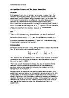
Fig 2.3.10.1-4: Edit of binary monitoring channel, page 2.
In this window the following fields can be edited: - Input definition:
Select between Open contact = Alarm and Closed contact = Alarm
- Message text / Normal state:
Click on the button and select one of the texts. The selected text will be displayed when the channel is in normal state.
- Message Text (Limit 1):
Click on the button and select one of the texts. The selected text will be displayed when the channel is in alarm state due to limit 1. Normally there is only one alarm limit for a binary channel, but it is possible to define more limits with different delays and priority.
- Priority:
Click on the
button and select 1, 2, 3 or 4.
1 is the highest priority, alarms are indicated with red colour. 2 alarms is indicated in magenta colour.
Lyngsø Marine 970.505.742
Page 44 of 53 2001.06.01
UCS 2100, User Manual Operating instruction for Graphic Operator Station (GOS)
3 alarms is indicated in yellow colour. 4 event is indicated in white colour, priority 4 is only an indication of events and will not be included in the alarm list or alarm announcement, but will be included in the alarm/even list. - Delay on:
Delay from the contact goes in alarm state till the alarm is announced, the delay can be set from 0 to 650 seconds.
- Delay off:
Delay from contact goes to normal state before the alarm channel goes back to normal, the delay can be set from 0 to 650 seconds.
When the fields in this window are corrected click on the Finish button and the definition of the new monitoring channel will be transferred to the Gamma PLC and the other operator stations. The new monitoring channel will be active immediately.
Lyngsø Marine 970.505.742
Page 45 of 53 2001.06.01
UCS 2100, User Manual Operating instruction for Graphic Operator Station (GOS)
2.3.13.2 Activate analog channels. When you have selected the type of analog sensor and the PLC to which the sensor shall be connected, you will se a list like the one shown below:
Fig 2.3.10.2-1: List of vacant analog spare channels in PLC 1.
Select the channel you want to activate by clicking on the line, and then click on the Edit button, and the window below will appear.
Fig 2.3.10.2-2: Activate channel definition.
Click on the Activate field , to open the first page of the channel definition, and then the following window will appear.
Lyngsø Marine 970.505.742
Page 46 of 53 2001.06.01
UCS 2100, User Manual Operating instruction for Graphic Operator Station (GOS)
Fig 2.3.10.2-3: Edit of analog monitoring channel, page 1.
In this window the following fields can be edited: - ID:
Write the new ID for this channel, max. 8 characters.
- Name:
Write the new name for this channel, max. 30 characters.
- Type:
Only ANALOG is possible.
- Alarm System:
Select the alarm system in which the new monitoring channel shall be included.
- Incl in Data Log: - Alarm Groups:
Mark this field if the channel shall be included in the data log on the printer. The channel is always included in the alarm-even list. Select the alarm groups in which the channel shall be included, by selecting a group and then click on the Add button. One channel can be included in up to 4 different alarm groups or none.
After this page is finished click on the Next button and next page will appear.
Lyngsø Marine 970.505.742
Page 47 of 53 2001.06.01
UCS 2100, User Manual Operating instruction for Graphic Operator Station (GOS)
Fig 2.3.10.2-4: Edit of analog monitoring channel, page 2.
In this window the following fields can be edited: - Input scaling block:
Click on the button and select one of the predefined scaling blocks.
- Message text / Normal state:
Click on the button and select one of the texts. The selected text will be displayed when the channel is in normal state.
- Alarm Limit 1: - Type:
Click on the button and select the type of function for this alarm, select between NOT USED, LOW LIMIT and HIGH LIMIT. -
NOT USED means that there is no alarm based on this limit.
-
LOW LIMIT means that alarm is generated if the value of
Lyngsø Marine 970.505.742
Page 48 of 53 2001.06.01
UCS 2100, User Manual Operating instruction for Graphic Operator Station (GOS)
the monitoring channel is below the value of this limit for a longer time than specified in Delay on. -
HIGH LIMIT means that alarm is generated if the value of the monitoring channel is above the value of this limit for a longer time than specified in Delay on.
- Message Text:
Click on the button and select one of the texts. The selected text will be displayed when the channel is in alarm state due to limit 1.
- Priority:
Click on the
button and select 1, 2, 3 or 4.
1 is the highest priority, alarms are indicated with red colour. 2 alarms is indicated in magenta colour. 3 alarms is indicated in yellow colour. 4 event is indicated in white colour, priority 4 is only an indication of events and will not be included in the alarm list or alarm announcement, but will be included in the alarm/even list. - Limit Value:
The value of this limit. Alarm will be generated if the value of the monitoring channel exceeds this limit, alarm for lower value if “Type” is LOW LIMIT and alarm for higher value if “Type” is HIGH LIMIT
- Delay on:
Delay from the contact goes in alarm state till the alarm is announced, the delay can be set from 0 to 650 seconds.
- Delay off:
Delay from contact gos to normal state before the alarm channel goes back to normal, the delay can be set from 0 to 650 seconds.
- Limit 2
A monitoring channel can have op to 3 alarm limits. If type for limit 2 is selected different form NOT USED parameters for the second alarm limit can be keyed in, and Limit 3 is made visible. The meaning of parameters for limit 2 and 3 is the same as described above for limit 1.
When the fields in this window are corrected click on the Finish button and the definition of the new monitoring channel will be transferred to the Gamma PLC and the other operator stations. The new monitoring channel will be active immediately.
Lyngsø Marine 970.505.742
Page 49 of 53 2001.06.01
UCS 2100, User Manual Operating instruction for Graphic Operator Station (GOS)
2.3.14 Change definition of alarm channels, e.g. name, texts and scaling. From the operator station it is possible to make some changes in definition of alarm channels online. The parameters that can be changed are: - Name of the channel - Membership of Alarm System - Membership of Alarm Groups - Input definition NO or NC for binary channels - Input scaling block for analog channels - Message text - Alarm priority For some channels some of the parameters are locked e.g. if the channel is used by the control system. Changes in a channel will be active immediately after closing the definition window by clicking the OK button. The changes will be transferred to the other operator stations and the PLC’s (for printer and panel indication). Changes can be uploaded by a service engineer and imported in the system database, also changes of alarm limits, delays and hour counter values can be uploaded and imported. This means that changes will not get lost in case of a new generation and download of the database. NB: Changes are not included in the backup of the PLC code that is present on the operator stations. This means that changes will be lost if a PLC is loaded from the SystemStatus diagram on the operator station, e.g. after replacement of faulty PLC. On the other hand this can also be use to clean up a system if some unsuccessful changes have been made. Because of this it is important to write down all changes made online, so you are able to remake the changes in case of a new download is needed. Changes in alarm channel definition. - Open the Display Channel Diagram for the channel in question, se section 2.3.7. - Click on the Edit button below will be opened.
in the toolbar in the bottom of the window, the diagram
Lyngsø Marine 970.505.742
Page 50 of 53 2001.06.01
UCS 2100, User Manual Operating instruction for Graphic Operator Station (GOS)
Channel Definition, Main page.
On this page Name, Alarm System, Included in data log and Alarm Groups can be changed. Click on the Input/Limits tab analog channel.
to change to next page, shown below for an
Lyngsø Marine 970.505.742
Page 51 of 53 2001.06.01
UCS 2100, User Manual Operating instruction for Graphic Operator Station (GOS)
On this page Input scaling block and message texts can be changed. The Channel Definition diagrams are the same as used for activation of spare channels, so for details about the parameters refer to the two sections 2.3.13.1 Activate binary channels and 2.3.13.2 Activate analog channels.
Lyngsø Marine 970.505.742