![Asme Pvho-1-2019 [PDF]](https://pdfs.asia/img/200x200/asme-pvho-1-2019.jpg)
14 0 7 MB
ASME PVHO-1–2019 (Revision of ASME PVH O-1 –201 6)
Safety Standard for Pressure Vessels for Human Occupancy
A N A M E R I C A N N A T I O N A L S TA N D A R D
ASME PVHO-1– 2019
(Revision of ASME PVHO-1– 2016)
Safety Standard for Pressure Vessels for Human Occupancy
AN AMERICAN NATIONAL STANDARD
Date of Issuance: January 24, 2020
The next edition of this Standard is scheduled for publication in 2022. ASME issues written replies to inquiries concerning interpretations of technical aspects of this Standard. Periodically certain actions of the ASME PVHO Committee may be published as Cases. Cases and interpretations are published on the ASME website under the Committee Pages at http://cstools.asme.org/ as they are issued. Errata to codes and standards may be posted on the ASME website under the Committee Pages to provide corrections to incorrectly published items, or to correct typographical or grammatical errors in codes and standards. Such errata shall be used on the date posted. The Committee Pages can be found at http://cstools.asme.org/. There is an option available to automatically receive an e-mail notification when errata are posted to a particular code or standard. This option can be found on the appropriate Committee Page after selecting “Errata ” in the “Publication Information ” section.
ASME is the registered trademark of The American Society of Mechanical Engineers. This code or standard was developed under procedures accredited as meeting the criteria for American National Standards. The Standards Committee that approved the code or standard was balanced to assure that individuals from competent and concerned interests have had an opportunity to participate. The proposed code or standard was made available for public review and comment that provides an opportunity for additional public input from industry, academia, regulatory agencies, and the public-at-large. ASME does not “approve,” “rate,” or “endorse ” any item, construction, proprietary device, or activity. ASME does not take any position with respect to the validity of any patent rights asserted in connection with any items mentioned in this document, and does not undertake to insure anyone utilizing a standard against liability for infringement of any applicable letters patent, nor assume any such liability. Users of a code or standard are expressly advised that determination of the validity of any such patent rights, and the risk of infringement of such rights, is entirely their own responsibility. Participation by federal agency representative(s) or person(s) affiliated with industry is not to be interpreted as government or industry endorsement of this code or standard. ASME accepts responsibility for only those interpretations of this document issued in accordance with the established ASME procedures and policies, which precludes the issuance of interpretations by individuals. No part of this document may be reproduced in any form, in an electronic retrieval system or otherwise, without the prior written permission of the publisher. The American Society of Mechanical Engineers Two Park Avenue, New York, NY 10016-5990 Copyright © 2020 by THE AMERICAN SOCIETY OF MECHANICAL ENGINEERS All rights reserved Printed in U.S.A.
CONTENTS Foreword
. . . . . . . . . . . . . . . . . . . . . . . . . . . . . . . . . . . . . . . . . . . . . . . . . . . . . . . . . . . . . . . . . . . . . . . .
Committee Roster
. . . . . . . . . . . . . . . . . . . . . . . . . . . . . . . . . . . . . . . . . . . . . . . . . . . . . . . . . . . . . . . . . .
Correspondence With the PVHO Committee Summary of Changes
viii ix
. . . . . . . . . . . . . . . . . . . . . . . . . . . . . . . . . . . . . . . . . . . . . . .
xii
. . . . . . . . . . . . . . . . . . . . . . . . . . . . . . . . . . . . . . . . . . . . . . . . . . . . . . . . . . . . . . .
xiv
Section 1
General Requirements
1-1
Introduction
. . . . . . . . . . . . . . . . . . . . . . . . . . . . . . . . . . . . . . . . . . . . . . . . .
1
. . . . . . . . . . . . . . . . . . . . . . . . . . . . . . . . . . . . . . . . . . . . . . . . . . . . . . . .
1
. . . . . . . . . . . . . . . . . . . . . . . . . . . . . . . . . . . . . . . . . . . . . . . . . . . . . . . . . . . . .
1
1-2
Scope
1-3
Exclusions
. . . . . . . . . . . . . . . . . . . . . . . . . . . . . . . . . . . . . . . . . . . . . . . . . . . . . . . . .
1-4
User Requirements
1-5
Manufacturer's Data Report
1-6
Materials
. . . . . . . . . . . . . . . . . . . . . . . . . . . . . . . . . . . . . . . . . . . . . . . . . . .
1 1
. . . . . . . . . . . . . . . . . . . . . . . . . . . . . . . . . . . . . . . . . . . . .
1
. . . . . . . . . . . . . . . . . . . . . . . . . . . . . . . . . . . . . . . . . . . . . . . . . . . . . . . . . .
2
1-7
Design and Fabrication Requirements
1-8
Pressure Relief Devices
. . . . . . . . . . . . . . . . . . . . . . . . . . . . . . . . . . . . . .
2
. . . . . . . . . . . . . . . . . . . . . . . . . . . . . . . . . . . . . . . . . . . . . . . .
9
. . . . . . . . . . . . . . . . . . . . . . . . . . . . . . . . . . . . . . . . . . . . . . . . . . . . . . . . . . .
9
1-9
Marking
1-10
Nonmetallic Materials and Toxicity Off-Gas Testing
1-11
Risk Analysis
1-12
Lithium Batteries
1-13
Automatic Control and Software Safety
1-14
Operational Pressure Cycle
Section 2
Viewports
2-1
General
2-2
Design
2-3
Material
. . . . . . . . . . . . . . . . . . . . . . . . . . . .
9
. . . . . . . . . . . . . . . . . . . . . . . . . . . . . . . . . . . . . . . . . . . . . . . . . . . . . . .
10
. . . . . . . . . . . . . . . . . . . . . . . . . . . . . . . . . . . . . . . . . . . . . . . . . . . . . . . . . . . . . . . . . . . . . . . . . . . . . . . . . . . . . . . . .
10 12
. . . . . . . . . . . . . . . . . . . . . . . . . . . . . . . . . . . . . . . . . . . . .
12
. . . . . . . . . . . . . . . . . . . . . . . . . . . . . . . . . . . . . . . . . . . . . . . . . . . . . . . . . .
19
. . . . . . . . . . . . . . . . . . . . . . . . . . . . . . . . . . . . . . . . . . . . . . . . . . . . . . . . . . . .
19
. . . . . . . . . . . . . . . . . . . . . . . . . . . . . . . . . . . . . . . . . . . . . . . . . . . . . . . . . . . .
19
. . . . . . . . . . . . . . . . . . . . . . . . . . . . . . . . . . . . . . . . . . . . . . . . . . . . . . . . . . .
2-4
Fabrication
2-5
Inspection
30
. . . . . . . . . . . . . . . . . . . . . . . . . . . . . . . . . . . . . . . . . . . . . . . . . . . . . . . . .
33
. . . . . . . . . . . . . . . . . . . . . . . . . . . . . . . . . . . . . . . . . . . . . . . . . . . . . . . . . .
33
2-6
Marking
2-7
Pressure Testing
2-8
Installation of Windows in Chambers
2-9
Repair of Damaged Windows Prior to Being Placed in Service
2-10
Guidelines for Application of the Requirements of Section 2
. . . . . . . . . . . . . . . . . . . . . . . . . . . . . . . . . . . . . . . . . . . . . . . . . . . . . . . . . . . . . . . . . . . . . . . . . . . . . . . . . . . . . . . . . . . . . . . . . . . . . . . . . . . . . . . . . . . . . . . . . . . . . . . . . . . . . . . . . . . . . . . . . . . . . .
35 36 36
. . . . . . . . .
37
. . . . . . . . . . . . . . . . . . . . . .
38
. . . . . . . . . . . . . . . . . . . . . . . . . . . . . . . . . .
88
. . . . . . . . . . . . . . . . . . . . . . . . . . . . . . . . . . . . . . . . . . . . . . . . . . . . . . . . . . . .
88
Section 3
Quality Assurance for PVHO Manufacturers
3-1
General
.
. . .
. . . . . . .
3-2
Responsibilities
. . . . . . . . . . . . . . . . . . . . . . . . . . . . . . . . . . . . . . . . . . . . . . . . . . . . . .
88
Section 4
Piping Systems
. . . . . . . . . . . . . . . . . . . . . . . . . . . . . . . . . . . . . . . . . . . . . . . . . . . . . .
89
4-1
General
. . . . . . . . . . . . . . . . . . . . . . . . . . . . . . . . . . . . . . . . . . . . . . . . . . . . . . . . . . . .
89
4-2
Material Requirements
. . . . . . . . . . . . . . . . . . . . . . . . . . . . . . . . . . . . . . . . . . . . . . . .
89
4-3
Design of Components
. . . . . . . . . . . . . . . . . . . . . . . . . . . . . . . . . . . . . . . . . . . . . . . . .
91
4-4
Selection and Limitations of Piping Components
iii
. . . . . . . . . . . . . . . . . . . . . . . . . . . . . .
92
4-5
Selection and Limitations of Piping Joints
. . . . . . . . . . . . . . . . . . . . . . . . . . . . . . . . . . .
93
4-6
Supports
. . . . . . . . . . . . . . . . . . . . . . . . . . . . . . . . . . . . . . . . . . . . . . . . . . . . . . . . . . .
94
4-7
Inspection
4-8
Testing
4-9
Systems
Section 5
Medical Hyperbaric Systems
. . . . . . . . . . . . . . . . . . . . . . . . . . . . . . . . . . . . . . . . . . . . . . . . . . . . . . . . . .
94
. . . . . . . . . . . . . . . . . . . . . . . . . . . . . . . . . . . . . . . . . . . . . . . . . . . . . . . . . . . .
95
. . . . . . . . . . . . . . . . . . . . . . . . . . . . . . . . . . . . . . . . . . . . . . . . . . . . . . . . . . .
5-1
General
5-2
PVHO System Design
5-3
Gas Systems
. . . . . . . . . . . . . . . . . . . . . . . . . . . . . . . . . . . . . . . . . . . .
. . . . . . . . . . . . . . . . . . . . . . . . . . . . . . . . . . . . . . . . . . . . . . . . . . . . . . . . . . . .
95 103 103
. . . . . . . . . . . . . . . . . . . . . . . . . . . . . . . . . . . . . . . . . . . . . . . . . .
104
. . . . . . . . . . . . . . . . . . . . . . . . . . . . . . . . . . . . . . . . . . . . . . . . . . . . . . . .
104
5-4
Control Systems and Instrumentation
5-5
Environmental Systems
Section 6
Diving Systems
6-1
General
6-2
Design
6-3
Pressure Boundary
6-4
Systems
6-5
Handling Systems
6-6
Hyperbaric Evacuation Systems
6-7
Testing and Trials
Section 7
Submersibles
7-1
General
. . . . . . . . . . . . . . . . . . . . . . . . . . . . . . . . . . . . . .
104
. . . . . . . . . . . . . . . . . . . . . . . . . . . . . . . . . . . . . . . . . . . . . . . .
104
. . . . . . . . . . . . . . . . . . . . . . . . . . . . . . . . . . . . . . . . . . . . . . . . . . . . . .
106
. . . . . . . . . . . . . . . . . . . . . . . . . . . . . . . . . . . . . . . . . . . . . . . . . . . . . . . . . . . .
106
. . . . . . . . . . . . . . . . . . . . . . . . . . . . . . . . . . . . . . . . . . . . . . . . . . . . . . . . . . . .
107
. . . . . . . . . . . . . . . . . . . . . . . . . . . . . . . . . . . . . . . . . . . . . . . . . . .
108
. . . . . . . . . . . . . . . . . . . . . . . . . . . . . . . . . . . . . . . . . . . . . . . . . . . . . . . . . . .
110
. . . . . . . . . . . . . . . . . . . . . . . . . . . . . . . . . . . . . . . . . . . . . . . . . . . .
114
. . . . . . . . . . . . . . . . . . . . . . . . . . . . . . . . . . . . . . . . . .
115
. . . . . . . . . . . . . . . . . . . . . . . . . . . . . . . . . . . . . . . . . . . . . . . . . . . .
117
. . . . . . . . . . . . . . . . . . . . . . . . . . . . . . . . . . . . . . . . . . . . . . . . . . . . . . .
119
. . . . . . . . . . . . . . . . . . . . . . . . . . . . . . . . . . . . . . . . . . . . . . . . . . . . . . . . . . . .
119
7-2
Pressure Boundary
7-3
Piping
. . . . . . . . . . . . . . . . . . . . . . . . . . . . . . . . . . . . . . . . . . . . . . . . . . .
120
. . . . . . . . . . . . . . . . . . . . . . . . . . . . . . . . . . . . . . . . . . . . . . . . . . . . . . . . . . . . .
121
7-4
Electrical Systems
7-5
Life Support
. . . . . . . . . . . . . . . . . . . . . . . . . . . . . . . . . . . . . . . . . . . . . . . . . . . .
121
. . . . . . . . . . . . . . . . . . . . . . . . . . . . . . . . . . . . . . . . . . . . . . . . . . . . . . . .
122
7-6
Fire Protection
7-7
Navigation
7-8
Communications
. . . . . . . . . . . . . . . . . . . . . . . . . . . . . . . . . . . . . . . . . . . . . . . . . . . . .
7-9
Instrumentation
. . . . . . . . . . . . . . . . . . . . . . . . . . . . . . . . . . . . . . . . . . . . . . . . . . . . .
7-10
Buoyancy, Stability, Emergency Ascent, and Entanglement
7-11
Emergency Equipment
. . . . . . . . . . . . . . . . . . . . . . . . . . . . . . . . . . . . . . . . . . . . . . . . . . . . . .
123
. . . . . . . . . . . . . . . . . . . . . . . . . . . . . . . . . . . . . . . . . . . . . . . . . . . . . . . . .
123 124 124
. . . . . . . . . . . . . . . . . . . . . . .
124
. . . . . . . . . . . . . . . . . . . . . . . . . . . . . . . . . . . . . . . . . . . . . . . . .
125
Mandatory Appendices I
Reference Codes, Standards, and Specifications
II
Definitions
. . . . . . . . . . . . . . . . . . . . . . . . . . . . . . .
126
. . . . . . . . . . . . . . . . . . . . . . . . . . . . . . . . . . . . . . . . . . . . . . . . . . . . . . . . .
128
Nonmandatory Appendices A
Design of Supports and Lifting Attachments
. . . . . . . . . . . . . . . . . . . . . . . . . . . . . . . . .
134
B
Recommendations for the Design of Through-Pressure Boundary Penetrations
C
Recommended Practices for Color Coding and Labeling
.
135
. . . . . . . . . . . . . . . . . . . . . . . . .
138
D
Guidelines for the Submission of a Case for the Use of Nonstandard Designs, Materials, and Construction for Non-Flexible PVHO Chamber Fabrication . . . . . . . . . . . . . . . . . . . . .
139
E
Guidelines for Preparing a Performance-Based Case for Flexible PVHO Chambers and Systems
146
F
Useful References
176
.
.
.
.
.
.
.
. . . . . . . . . . . . . . . . . . . . . . . . . . . . . . . . . . . . . . . . . . . . . . . . . . . .
iv
Figures 15
1-7.13.1-1
Geometry of Cylinders
1-7.13.1-2
Stiffener Geometry
1-7.13.1-3
Sections Through Rings
1-7.13.5-1
Values of t/ Ro and L c/ Ro
1-9-1
Form of Nameplate, U.S. Customary Units
1-9-2
Form of Nameplate, SI Units
2-2.2.1-1
Standard Window Geometries — Part 1
. . . . . . . . . . . . . . . . . . . . . . . . . . . . . . . . . . . .
43
2-2.2.1-2
Standard Window Geometries — Part 2
. . . . . . . . . . . . . . . . . . . . . . . . . . . . . . . . . . . .
44
2-2.2.1-3
Standard Window Geometries — Part 3
. . . . . . . . . . . . . . . . . . . . . . . . . . . . . . . . . . . .
45
2-2.2.1-4
Standard Window Geometries — Part 4
. . . . . . . . . . . . . . . . . . . . . . . . . . . . . . . . . . . .
46
. . . . . . . . . . . . . . . . . . . . . . . . . . . . . . . . . . . . . . . . . . . . . . . . .
. . . . . . . . . . . . . . . . . . . . . . . . . . . . . . . . . . . . . . . . . . . . . . . . . . . . . . . . . . . . . . . . . . . . . . . . . . . . . . . . . . . . . . . . . . . . . . . . . . . . . . . . . . . . . . . . . . . . . . . . . . . . . . . . . . . . . . . . . . . . . . . . . . . . . . . . . . . . . . . . . . . . . . . . . . . . . . . . . . . . .
. . . . . . . . . . . . . . . . . . . . . . . . . . . . . . . . . . . . . . . . . . . .
16 16 17 18 18
2-2.5.1-1
Short-Term Critical Pressure of Flat Disk Acrylic Windows — Part 1
.
.
.
.
.
.
.
.
.
.
.
.
.
.
.
49
2-2.5.1-2
Short-Term Critical Pressure of Flat Disk Acrylic Windows — Part 2
.
.
.
.
.
.
.
.
.
.
.
.
.
.
.
50
2-2.5.1-3
Short-Term Critical Pressure of Flat Disk Acrylic Windows — Part 3
.
.
.
.
.
.
.
.
.
.
.
.
.
.
.
51
2-2.5.1-4
Short-Term Critical Pressure of Conical Frustum Acrylic Windows — Part 1
.
.
.
.
.
. .
.
. .
52
2-2.5.1-5
Short-Term Critical Pressure of Conical Frustum Acrylic Windows — Part 2
.
.
.
.
.
. .
.
. .
53
2-2.5.1-6
Short-Term Critical Pressure of Spherical Sector Acrylic Windows — Part 1
.
.
.
.
.
.
.
.
.
.
54
2-2.5.1-7
Short-Term Critical Pressure of Spherical Sector Acrylic Windows — Part 2
.
.
.
.
.
.
.
.
.
.
55
2-2.5.1-8
Short-Term Critical Pressure of Cylindrical Acrylic Windows Pressurized Internally — Part 1
56
2-2.5.1-9
Short-Term Critical Pressure of Cylindrical Acrylic Windows Pressurized Internally — Part 2
57
2-2.5.1-10
Short-Term Critical Pressure of Cylindrical Acrylic Windows Pressurized Externally
.
58
2-2.5.1-11
Short-Term Elastic Buckling of Cylindrical Acrylic Windows Between Supports Under External Hydrostatic Pressure — Part 1 . . . . . . . . . . . . . . . . . . . . . . . . . . . . . . . . . . . . . . . .
59
2-2.5.1-12
Short-Term Elastic Buckling of Cylindrical Acrylic Windows Between Supports Under External Hydrostatic Pressure — Part 2 . . . . . . . . . . . . . . . . . . . . . . . . . . . . . . . . . . . . . . . .
60
2-2.5.1-13
Short-Term Elastic Buckling of Cylindrical Acrylic Windows Between Supports Under External Hydrostatic Pressure — Part 3 . . . . . . . . . . . . . . . . . . . . . . . . . . . . . . . . . . . . . . . .
61
2-2.5.1-14
Short-Term Critical Pressure of Hyperhemispherical and NEMO-Type Acrylic Windows — Part 1 . . . . . . . . . . . . . . . . . . . . . . . . . . . . . . . . . . . . . . . . . . . . . . . . . . . . . . . . . .
62
2-2.5.1-15
Short-Term Critical Pressure of Hyperhemispherical and NEMO-Type Acrylic Windows — Part 2 . . . . . . . . . . . . . . . . . . . . . . . . . . . . . . . . . . . . . . . . . . . . . . . . . . . . . . . . . .
63
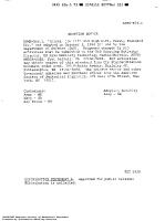
2-2.10.1-1
Seat Cavity Requirements — Conical Frustum Window, Spherical Sector Window With Conical Edge, and Flat Disk Window . . . . . . . . . . . . . . . . . . . . . . . . . . . . . . . . . . . . . . . . . .
64
.
.
.
2-2.10.1-2
Seat Cavity Requirements — Double-Beveled Disk Window
2-2.10.1-3
Seat Cavity Requirements — Spherical Sector Window With Square Edge
2-2.10.1-4
Seat Cavity Requirements — Hemispherical Window With Equatorial Flange
2-2.10.1-5
Seat Cavity Requirements — Cylindrical Window
2-2.10.1-6
Seat Cavity Requirements — Hyperhemispherical Window
2-2.10.1-7
Seat Cavity Requirements — NEMO Window (Standard Seat)
2-2.10.1-8
Seat Cavity Requirements — NEMO Window (Seat With Extended Cyclic Fatigue Life)
.
71
2-2.11.10-1
Bevels on Window Edges — Flat Disk Windows, Conical Frustum Windows, Spherical Sector Windows, Hyperhemispheres . . . . . . . . . . . . . . . . . . . . . . . . . . . . . . . . . . . . . . . . . .
72
2-2.11.10-2
Bevels on Window Edges — Flanged Hemispherical Window, Spherical Sector Window With Square Edge, External Pressure and Internal Pressure of Cylindrical Windows . . . . . .
73
. . . . . .
. . . . . . . . . . . . . . . . . . . . . .
. . . . . .
.
. .
. . .
65 66
.
67
. .
. .
. . .
. .
. .
68
.
.
.
.
.
.
.
.
.
.
.
.
.
.
69
. . . . . . . . . . . . . . . . . . . . .
70
.
2-2.11.11-1
Acceptable Configurations for Clear Viewport Retaining Covers
2-2.14.11-1
Dimensional Tolerances for Penetrations in Acrylic Windows
2-2.14.15-1
Dimensional Tolerances for Inserts in Acrylic Windows v
. .
. . . . . . . . . . . .
.
.
.
.
.
.
.
.
.
.
.
.
.
.
. .
74
. . . . . . . . . . . . . . . . . . . . .
75
. . . . . . . . . . . . . . . . . . . . . . . . .
77
. .
.
.
.
.
. .
.
. .
. .
.
.
.
.
2-2.14.16-1
Typical Shapes of Inserts
2-2.14.22-1
Seal Configurations for Inserts in Acrylic Windows
. . . . . . . . . . . . . . . . . . . . . . . . . . . . . . . . . . . . . . . . . . . . . . .
78
. . . . . . . . . . . . . . . . . . . . . . . . . . . .
79
2-2.14.24-1
Restraints for Inserts in Acrylic Windows
. . . . . . . . . . . . . . . . . . . . . . . . . . . . . . . . . . .
80
4-9.14.2-1
Flow Diagram of Apparatus for Measuring the Concentration of Hydrocarbons in a Stream of Air or Other Gas After It Has Passed Through a Test Hose . . . . . . . . . . . . . . . . . . . . .
102
6-6.2.2-1
Placement and Design of Markings for Hyperbaric Evacuation Units Designed to Float in Water
118
6-6.2.2-2
Markings for Hyperbaric Evacuation Units Designed to Float in Water
.
118
. . . . . . . . . . . . . . . . . . . . . . . . . . . . . . . . . . . . . . .
136
. . . . . . . . . . . . . . . . . . . . . . . . . . . . . . . . . . . . . . . . . .
137
B-2-1
Acceptable Weld Nozzle Penetrators
B-3-1
Acceptable Threads and Inserts
E-3.3.1-1
Cook’s Diagram: Atmosphere of Increased Burning Rate
E-5.2.2.1-1
Number of Test Samples Required for Alternate Creep Test Procedure
E-5.2.5.1-1
Time Versus Test Temperature for Accelerated Aging Test
.
. .
.
.
.
. .
.
. .
.
.
.
. .
.
.
.
.
.
.
.
.
.
.
.
.
.
.
.
.
.
.
. .
.
.
.
. . . . . . . . . . . . . .
.
.
.
.
.
.
.
.
.
.
.
.
.
.
.
.
.
.
.
.
.
.
.
.
.
.
.
.
.
.
.
.
.
.
.
.
.
.
.
173 174 175
Tables
Fp (for PVHO Occupation Exceeding 8 hr)
1-10-1
Conversion Factor,
.
18
2-2.3.1-1
Conversion Factors for Acrylic Flat Disk Windows
. . . . . . . . . . . . . . . . . . . . . . . . . . . . .
46
2-2.3.1-2
Conversion Factors for Acrylic Conical Frustum Windows and Double-Beveled Disk Windows
47
2-2.3.1-3
Conversion Factors for Acrylic Spherical Sector Windows With Conical Edge, Hyperhemispherical Windows With Conical Edge, and NEMO-Type Windows With Conical Edge . . . . . . . . . . . . . . . . . . . . . . . . . . . . . . . . . . . . . . . . . . . . . . . . . . . . . . . . . . .
47
2-2.3.1-4
Conversion Factors for Acrylic Spherical Sector Windows With Square Edge and Hemispherical Windows With Equatorial Flange . . . . . . . . . . . . . . . . . . . . .
. . . . . . .
48
2-2.3.1-5
Conversion Factors for Acrylic Cylindrical Windows
.
.
48
2-2.3.2-1
Conical Frustum Windows for Design Pressures in Excess of 10,000 psi (69 MPa)
. . . . . .
49
2-2.14.13-1
Specified Values of Physical Properties for Polycarbonate Plastic
.
.
76
2-2.14.13-2
Specified Values of Physical Properties for Cast Nylon Plastic
. . . . . . . . . . . . . . . . . . . . .
76
.
. .
. .
.
. .
. .
.
.
.
. .
. .
. .
. .
.
.
. . . .
. .
. .
.
. .
.
.
. .
.
. .
2-3.4-1
Specified Values of Physical Properties for Each Lot
2-3.4-2
Specified Values of Physical Properties for Each Casting
. .
.
. .
. . . . .
. . . .
. . . . .
. . .
.
81
. .
.
.
. .
.
.
.
.
.
83
2-4.5-1
Annealing Schedule for Acrylic Windows
. . . .
.
85
4-2.1.1-1
Maximum Allowable Stress Values for Seamless Pipe and Tube Materials Not Listed in Nonmandatory Appendix A of ASME B31.1 . . . . . . . . . . . . . . . . . . . . . . . . . . . . . .
. .
101
4-7.1-1
Mandatory Minimum Nondestructive Examinations for Pressure Welds in Piping Systems for Pressure Vessels for Human Occupancy . . . . . . . . . . . . . . . . . . . . . . . . . . . . . . . . . .
101
4-9.14.2-1
Maximum Allowable Concentration of Hydrocarbons in Air Passing Through Hose
C-1
U.S. Navy Color Codes
. .
. . . .
.
. . . .
.
. . . . . . . . . . . .
.
.
.
. . . .
. .
.
.
.
.
. . . . . . . .
.
.
.
102
. . . . . . . . . . . . . . . . . . . . . . . . . . . . . . . . . . . . . . . . . . . . . . . . .
138
. . . . . . . . . . . . . . . . . . . . . . . . . . . . . . . . . . . . . . . . . . . . . . . . . . . . .
138
C-2
IMO Color Codes
D-7.1-1
Tabulated Data for Performance of “W-Test” for Normality of Data Set
E-1.1-1
Compliance Matrix for ASME PVHO-1 Cases
.
.
.
.
. . . . . . . . . . . . . .
145
. . . . . . . . . . . . . . . . . . . . . . . . . . . . . . . . .
159
Forms PVHO-1 GR-1
Manufacturer's Data Report for Pressure Vessels for Human Occupancy
PVHO-1 GR-1S
Manufacturer's Data Report Supplementary Sheet
PVHO-1 VP-1
Fabrication Certification for Acrylic Windows
PVHO-1 VP-2
Acrylic Window Design Certification
PVHO-1 VP-3
Material Manufacturer's Certification for Acrylic
PVHO-1 VP-4
Material Testing Certification for Acrylic
.
13
. . . . . . . . . . . . . . . . . . . . . . . . . . . . .
14
. . . .
. . .
. .
. . .
. . . . . . . . . . . . . . . . . . . . . . . . . . . . . . . .
41
. . . . . . . . . . . . . . . . . . . . . . . . . . . . . . . . . . . . . . .
42
vi
. . . . . . . . . . . . . . . . . . . . . . . . . . . . . .
82
. . . . . . . . . . . . . . . . . . . . . . . . . . . . . . . . . . . .
84
PVHO-1 VP-5
Pressure Testing Certification
PVHO-1 VP-6
Acrylic Window Repair Certification
. . . . . . . . . . . . . . . . . . . . . . . . . . . . . . . . . . . . . . . . . . . . . . . . . . . . . . . . . . . . . . . . . . . . . . . . . . . . . . . . . . .
vii
86 87
FOREWORD Early in 1971, an ad hoc committee was formed by action of the ASME Codes and Standards Policy Board to develop design rules for pressure vessels for human occupancy. The importance of this task was soon recognized, and the ASME Safety Code Committee on Pressure Vessels for Human Occupancy (PVHO) was established in 1974 to continue the work of the ad hoc committee. Initially, this committee was to confine its activity to the pressure boundary of such systems. It was to reference existing ASME Boiler and Pressure Vessel Code (BPVC) Sections, insofar as practicable, adapting them for application to pressure vessels for human occupancy. The common practice hitherto had been to design such chambers in accordance with Section VIII, Division 1 ofASME BPVC; however, a number ofimportant considerations were not covered in those rules. Among these were requirements for viewports and the in-service use of pressure relief valves, and special material toughness requirements. This Standard provides the necessary rules to supplement that Section, and also Section VIII, Division 2 of ASME BPVC. The user is expected to be familiar with the principles and application of the Code Sections. ASME BPVC criteria furnish the baseline for design. In ASME PVHO-1, design temperature is limited to 0°F to 150°F (−18°C to 66°C). Supporting structure and lifting loads are given special attention. Certain design details permitted by Section VIII are excluded. A major addition is the inclusion of design rules for acrylic viewports (Section 2). The formulation of rules for these vital and critical appurtenances was one of the reasons for establishing the PVHO Committee. Finally, all chambers designed for external pressure are required to be subjected to an external pressure hydrostatic test or pneumatic test. The 2007 edition was completely rewritten and reformatted from the 2002 edition. Section 1, General Requirements, is intended to be used for all PVHOs, regardless of use. The rules for external pressure design were expanded to include unstiffened and ring-stiffened cylinders, in addition to spheres. Other additions included Sections pertaining to application-specific PVHOs. Sections were included for medical hyperbaric systems, diving systems, submersibles, and quality assurance. The Piping Systems Section was expanded. Where possible, Mandatory Appendices were incorporated into the body of the Standard. All forms were revised to reflect the document (PVHO-1), an abbreviation denoting the corresponding section (e.g., General Requirements is GR), and the form number within that Section. An example is PVHO-1 Form GR-1. The 2012 edition included expansions made to the General Requirements, Viewports, and Diving Systems Sections. The 2016 edition included additional expansions made to the General Requirements, Viewports, Medical Hyperbaric Systems, and Diving Systems Sections. It included a new Nonmandatory Appendix for preparing PVHO performancebased Cases for flexible chambers. There is continuing work being accomplished by the Subcommittees in the areas of PVHOs using nonstandard materials, including nonmetallic PVHOs. A companion document (ASME PVHO-2) that covers in-service guidelines for PVHOs has been published. The 2019 edition of PVHO-1 continues the work to address complete PVHO systems and PVHOs made from nonstandard materials. In support ofthis work, definitions in Mandatory Appendix II and various forms were added or updated to reflect the differences in approach to documenting the entire PVHO system as a whole rather than as single or multiple pressure vessels/chambers. Additionally, changes were made to this edition in efforts to clarify several design standards and requirements for easier understanding and implementation by all users of this Standard. Interpretations, Code Cases, and errata to ASME PVHO-1 are published on the following ASME web page: https://cstools.asme.org/csconnect/CommitteePages.cfm?Committee=N10050000. The 2019 edition ofASME PVHO-1 was approved and adopted by the American National Standards Institute as meeting the criteria as an American National Standard on December 4, 2019. Previous editions were published in 1977, 1981, 1984, 1987, 1993, 1997, 2002, 2007, 2012, and 2016.
viii
ASME PRESSURE VESSELS FOR HUMAN OCCUPANCY COMMITTEE (The following is the roster of the Committee as of February 19, 2019.)
STANDARDS COMMITTEE OFFICERS G. Wolfe , Chair J. Witney, Vice Chair E. Lawson , Secretary
STANDARDS COMMITTEE PERSONNEL J. E. Crouch , Southwest Research Institute B. Faircloth , FMS Engineering, LLC M. A. Frey, Naval Sea Systems Command T. R. Galloway, Naval Sea Systems Command B. Kemper, Kemper Engineering Services, LLC W. Kohnen , Hydrospace Group, Inc. D. Lawrence , U.S. Coast Guard E. Lawson , The American Society of Mechanical Engineers S. Reimers , Reimers Systems, Inc. G. Richards , Blanson, Ltd. T. C. Schmidt, Lockheed Martin K. A. Smith , U.S. Coast Guard R. C. Smith , Naval Facilities Engineering Command, Ocean Facilities Program J. Stromer, Triton Submarines D. Talati , Sechrist Industries, Inc. R. Thomas , American Bureau of Shipping M. R. Walters , Oceaneering International, Inc.
J. Witney, Atlantis Submarines International G. Wolfe , Southwest Research Institute E. G. Fink, Delegate, Fink Engineering Pty., Ltd. H. Pauli , Delegate, Germanischer Lloyd AG J. S. Selby, Delegate, SOS Group Global, Ltd. L. Cross , Alternate, Kemper Engineering Services, LLC J. P. Hierholzer, Alternate, DNV GL J. K. Martin , Alternate, Perry Technologies P. Selby, Alternate, SOS Group Global, Ltd. M. W. Allen , Contributing Member, Microbaric Oxygen Systems, LLC W. F. Crowley, Jr. , Con tributin g Mem ber, Aerospace & Undersea Support Services, LLC W. Davison , Contributing Member G. J. Jacob , Contributing Member, Navy Experimental Diving Unit J. Maison , Contributing Member, Adaptive Computer Technology, Inc. T. Marohl , Contributing Member J. C. Sheffield, Contributing Member, International ATMO, Inc.
HONORARY MEMBERS R. J. Dzikowski F. T. Gorman
L. G. Malone , Plastic Supply & Fabric, Inc. R. P. Swanson
SPECIAL PROJECTS TASK GROUP J. Witney, Chair, Atlantis Submarines International J. E. Crouch , Southwest Research Institute E. G. Fink, Fink Engineering Pty., Ltd. M. A. Frey, Naval Sea Systems Command T. R. Galloway, Naval Sea Systems Command B. Kemper, Kemper Engineering Services, LLC W. Kohnen , Hydrospace Group, Inc. S. Reimers , Reimers Systems, Inc.
G. Richards , Blanson, Ltd. R. C. Smith, Naval Facilities Engineering Command, Ocean Facilities Program G. Wolfe , Southwest Research Institute L. Cross , Alternate, Kemper Engineering Services, LLC M. W. Allen , Contributing Member, Microbaric Oxygen Systems, LLC K. K. Kemper, Contributing Member, Kemper Engineering Services, LLC
TASK GROUP ON TUNNELING L. Cross , Kemper Engineering Services, LLC G. L. East, ASI Marine E. G. Fink, Fink Engineering Pty., Ltd. J. P. Hierholzer, DNV GL
B. Kemper, Kemper Engineering Services, LLC W. Kohnen , Hydrospace Group, Inc. S. Reimers , Reimers Systems, Inc. M. W. Allen , Contributing Member, Microbaric Oxygen Systems, LLC
ix
SUBCOMMITTEE ON DESIGN AND PIPING SYSTEMS T. C. Schmidt, Chair, Lockheed Martin B. Faircloth , Vice Chair, FMS Engineering, LLC E. Lawson , Secretary, The American Society of Mechanical Engineers G. Bryant, Consultant W. Davison R. K. Dixit, Reimers Systems, Inc. P. Forte , Woods Hole Oceanographic Institution M. A. Frey, Naval Sea Systems Command T. R. Galloway, Naval Sea Systems Command C. Gaumond , Groupe Medical Gaumond B. Humberstone , Diving Technical Advisor G. J. Jacob , Navy Experimental Diving Unit B. Kemper, Kemper Engineering Services, LLC S. Reimers , Reimers Systems, Inc. D. A. Renear, Aqua-Air Industries, Inc.
G. Richards , Blanson, Ltd. R. Thomas , American Bureau of Shipping M. R. Walters , Oceaneering International, Inc. J. S. Selby, Delegate, SOS Group Global, Ltd. L. Cross , Alternate, Kemper Engineering Services, LLC J. K. Martin , Alternate, Perry Technologies J. N. Pollack, Alternate, U.S. Navy P. Selby, Alternate, SOS Group Global, Ltd. R. M. Webb , Alternate, Naval Sea Systems Command M. W. Allen, Contributing Member, Microbaric Oxygen Systems, LLC F. Burman , Contributing Member, Divers Alert Network W. F. Crowley, Jr. , Con tributin g Mem ber, Aerospace & Undersea Support Services, LLC K. K. Kemper, Contributing Member, Kemper Engineering Services, LLC
SUBCOMMITTEE ON DIVING SYSTEMS R. Thomas , Chair, American Bureau of Shipping T. R. Galloway, Vice Chair, Naval Sea Systems Command E. Lawson , Secretary, The American Society of Mechanical Engineers G. Bryant, Consultant W. F. Crowley, Jr. , Aerospace & Undersea Support Services, LLC G. L. East, ASI Marine B. Faircloth , FMS Engineering, LLC B. Humberstone , Diving Technical Advisor B. Kemper, Kemper Engineering Services, LLC D. Lawrence , U.S. Coast Guard J. K. Martin , Perry Technologies D. A. Renear, Aqua-Air Industries, Inc.
J. S. Selby, SOS Group Global, Ltd. K. A. Smith, U.S. Coast Guard M. R. Walters , Oceaneering International, Inc. E. G. Fink, Delegate, Fink Engineering Pty., Ltd. H. Pauli , Delegate, Germanischer Lloyd AG L. Cross , Alternate, Kemper Engineering Services, LLC T. Gilman , Alternate, U.S. Coast Guard P. Selby, Alternate, SOS Group Global, Ltd. M. W. Allen, Contributing Member, Microbaric Oxygen Systems, LLC K. K. Kemper, Contributing Member, Kemper Engineering Services, LLC T. Marohl , Contributing Member
SUBCOMMITTEE ON GENERAL REQUIREMENTS M. A. Frey, Chair, Naval Sea Systems Command B. Kemper, Vice Chair, Kemper Engineering Services, LLC E. Lawson , Secretary, The American Society of Mechanical Engineers J. E. Crouch , Southwest Research Institute T. R. Galloway, Naval Sea Systems Command S. Reimers , Reimers Systems, Inc. J. Witney, Atlantis Submarines International
L. Cross , Alternate, Kemper Engineering Services, LLC J. N. Pollack, Alternate, U.S. Navy R. M. Webb , Alternate, Naval Sea Systems Command M. W. Allen, Contributing Member, Microbaric Oxygen Systems, LLC G. J. Jacob , Contributing Member, Navy Experimental Diving Unit K. K. Kemper, Contributing Member, Kemper Engineering Services, LLC
SUBCOMMITTEE ON MEDICAL HYPERBARIC SYSTEMS G. Richards , Chair, Blanson, Ltd. T. Dingman , Vice Chair, Healogics E. Lawson , Secretary, The American Society of Mechanical Engineers F. Burman , Divers Alert Network L. Cross , Kemper Engineering Services, LLC W. T. Gurnee , Oxyheal Health Group S. Reimers , Reimers Systems, Inc. R. C. Smith , Naval Facilities Engineering Command, Ocean Facilities Program D. Talati , Sechrist Industries, Inc.
E. G. Fink, Delegate, Fink Engineering Pty., Ltd. H. Pauli , Delegate, Germanischer Lloyd AG B. Kemper, Alternate, Kemper Engineering Services, LLC M. W. Allen, Contributing Member, Microbaric Oxygen Systems, LLC W. Davison , Contributing Member K. W. Evans , Contributing Member, Perry Baromedical K. K. Kemper, Contributing Member, Kemper Engineering Services, LLC J. C. Sheffield , Contributing Member, International ATMO, Inc. N. To , Contributing Member, U.S. Food and Drug Administration
x
SUBCOMMITTEE ON POST CONSTRUCTION J. E. Crouch , Chair, Southwest Research Institute R. C. Smith, Vice Chair, Naval Facilities Engineering Command, Ocean Facilities Program E. Lawson , Secretary, The American Society of Mechanical Engineers G. Bryant, Consultant T. Dingman , Healogics M. A. Frey, Naval Sea Systems Command T. R. Galloway, Naval Sea Systems Command D. R. Hurd , Atlantis Submarines International B. Kemper, Kemper Engineering Services, LLC W. Kohnen , Hydrospace Group, Inc. D. Lawrence , U.S. Coast Guard J. K. Martin , Perry Technologies G. Richards , Blanson, Ltd. D. Talati , Sechrist Industries, Inc. J. Witney, Atlantis Submarines International
L. Cross , Alternate, Kemper Engineering Services, LLC T. Gilman , Alternate, U.S. Coast Guard J. N. Pollack, Alternate, U.S. Navy R. M. Webb , Alternate, Naval Sea Systems Command M. W. Allen , Contributing Member, Microbaric Oxygen Systems, LLC J. Bell , Contributing Member, Fink Engineering Pty., Ltd. W. F. Crowley, Jr. , Con tributin g Mem ber, Aerospace & Undersea Support Services, LLC W. Davison , Contributing Member P. Forte , Contributing Member, Woods Hole Oceanographic Institution B. Humberstone , Contributing Member, Diving Technical Advisor G. J. Jacob , Contributing Member, Navy Experimental Diving Unit K. K. Kemper, Contributing Member, Kemper Engineering Services, LLC J. C. Sheffield, Contributing Member, International ATMO, Inc.
SUBCOMMITTEE ON SUBMERSIBLES R. Thomas , Chair, American Bureau of Shipping E. Lawson , Secretary, The American Society of Mechanical Engineers G. Bryant, Consultant J. P. Hierholzer, DNV GL D. R. Hurd , Atlantis Submarines International B. Kemper, Kemper Engineering Services, LLC W. Kohnen , Hydrospace Group, Inc. J. K. Martin , Perry Technologies K. A. Smith , U.S. Coast Guard J. Stromer, Triton Submarines M. R. Walters , Oceaneering International, Inc.
J. Witney, Atlantis Submarines International H. Pauli , Delegate, Germanischer Lloyd AG L. Cross , Alternate, Kemper Engineering Services, LLC D. Lawrence , Alternate, U.S. Coast Guard W. F. Crowley, Jr. , Con tributin g Mem ber, Aerospace & Undersea Support Services, LLC T. R. Galloway, Contributing Member, Naval Sea Systems Command K. K. Kemper, Contributing Member, Kemper Engineering Services, LLC R. M. Webb , Contributing Member, Naval Sea Systems Command
SUBCOMMITTEE ON VIEWPORTS B. Kemper, Chair, Kemper Engineering Services, LLC J. Witney, Vice Chair, Atlantis Submarines International E. Lawson , Secretary, The American Society of Mechanical Engineers G. Bryant, Consultant B. Faircloth , FMS Engineering, LLC D. R. Hurd , Atlantis Submarines International W. Kohnen , Hydrospace Group, Inc. D. Lawrence , U.S. Coast Guard D. A. Renear, Aqua-Air Industries, Inc. G. Richards , Blanson, Ltd.
R. C. Smith, Naval Facilities Engineering Command, Ocean Facilities Program J. Stromer, Triton Submarines D. Talati , Sechrist Industries, Inc. R. Thomas , American Bureau of Shipping L. Cross , Alternate, Kemper Engineering Services, LLC J. K. Martin , Alternate, Perry Technologies M. W. Allen , Contributing Member, Microbaric Oxygen Systems, LLC K. K. Kemper, Contributing Member, Kemper Engineering Services, LLC
xi
CORRESPONDENCE WITH THE PVHO COMMITTEE General. ASME Standards are developed and maintained with the intent to represent the consensus of concerned interests. As such, users of this Standard may interact with the Committee by requesting interpretations, proposing revisions or a case, and attending Committee meetings. Correspondence should be addressed to: Secretary, PVHO Standards Committee The American Society of Mechanical Engineers Two Park Avenue New York, NY 10016-5990 http://go.asme.org/Inquiry
Proposing Revisions. Revisions are made periodically to the Standard to incorporate changes that appear necessary or desirable, as demonstrated by the experience gained from the application of the Standard. Approved revisions will be published periodically. The Committee welcomes proposals for revisions to this Standard. Such proposals should be as specific as possible, citing the paragraph number(s), the proposed wording, and a detailed description of the reasons for the proposal, including any pertinent documentation. Proposing a Case. Cases may be issued to provide alternative rules when justified, to permit early implementation of an approved revision when the need is urgent, or to provide rules not covered by existing provisions. Cases are effective immediately upon ASME approval and shall be posted on the ASME Committee web page. Requests for Cases shall provide a Statement of Need and Background Information. The request should identify the Standard and the paragraph, figure, or table number(s), and be written as a Question and Reply in the same format as existing Cases. Requests for Cases should also indicate the applicable edition(s) of the Standard to which the proposed Case applies. Interpretations. Upon request, the PVHO Standards Committee will render an interpretation of any requirement of the Standard. Interpretations can only be rendered in response to a written request sent to the Secretary of the PVHO Standards Committee. Requests for interpretation should preferably be submitted through the online Interpretation Submittal Form. The form is accessible at http://go.asme.org/InterpretationRequest. Upon submittal of the form, the Inquirer will receive an automatic e-mail confirming receipt. If the Inquirer is unable to use the online form, he/she may mail the request to the Secretary of the PVHO Standards Committee at the above address. The request for an interpretation should be clear and unambiguous. It is further recommended that the Inquirer submit his/her request in the following format: Subject:
Cite the applicable paragraph number(s) and the topic of the inquiry in one or two words.
Edition:
Cite the applicable edition of the Standard for which the interpretation is being requested.
Question:
Phrase the question as a request for an interpretation of a specific requirement suitable for general understanding and use, not as a request for an approval of a proprietary design or situation. Please provide a condensed and precise question, composed in such a way that a “yes” or “no” reply is acceptable.
Proposed Reply(ies):
Provide a proposed reply(ies) in the form of “Yes” or “No,” with explanation as needed. If entering replies to more than one question, please number the questions and replies.
Background Information:
Provide the Committee with any background information that will assist the Committee in understanding the inquiry. The Inquirer may also include any plans or drawings that are necessary to explain the question; however, they should not contain proprietary names or information.
xii
Requests that are not in the format described above may be rewritten in the appropriate format by the Committee prior to being answered, which may inadvertently change the intent of the original request. Moreover, ASME does not act as a consultant for specific engineering problems or for the general application or understanding of the Standard requirements. If, based on the inquiry information submitted, it is the opinion of the Committee that the Inquirer should seek assistance, the inquiry will be returned with the recommendation that such assistance be obtained. ASME procedures provide for reconsideration of any interpretation when or if additional information that might affect an interpretation is available. Further, persons aggrieved by an interpretation may appeal to the cognizant ASME Committee or Subcommittee. ASME does not “approve,” “certify,” “rate,” or “endorse” any item, construction, proprietary device, or activity.
Attending Committee Meetings. The PVHO Standards Committee regularly holds meetings and/or telephone conferences that are open to the public. Persons wishing to attend any meeting and/or telephone conference should contact the Secretary of the PVHO Standards Committee.
xiii
ASME PVHO-1– 2019 SUMMARY OF CHANGES Following approval by the ASME PVHO-1 Committee and ASME, and after public review, ASME PVHO-1–2019 was approved by the American National Standards Institute on December 4, 2019. ASME PVHO-1–2019 includes the following changes identified by a margin note, (19) . Page
Location
Change
2
1-7.1
Subparagraphs (c)(1) through (c)(3) revised
3
1-7.8
Subparagraph (c) added
4
1-7.9
Subparagraph (k) revised
8
1-7.14
Subparagraph (f) added
10
1-12
Added
12
1-13
Added
12
1-14
Added
19
2-2.1
Revised
24
2-2.8.3
Title revised
32
2-3.8
(1) First paragraph and subpara. (a) revised (2) In subpara. (b), second sentence corrected by errata to read “acrylic plastic weighing about”
32
2-3.11
Added
34
2-5.4.1
Added
35
2-6.1
Revised
36
2-7.3
Revised
42
PVHO-1 Form VP-2
Revised
89
4-1.2
(1) Former para. 4-1.2.3 redesignated as subpara. 4-1.2.2(c) (2) Paragraph 4-1.2.4 redesignated as para. 4-1.2.3 (3) Paragraph 4-1.2.5 deleted
101
Table 4-7.1-1
General Note (b) corrected by errata to read MT
103
5-1.4
Revised in its entirety
104
5-1.9
Added
104
5-2
Revised
104
5-3.2
First paragraph revised
106
Section 6
Revised in its entirety
128
Mandatory Appendix II
(1) Definitions of air-ventilated PVHO, fabricator, manufacturer, material manufacturer, Professional Engineer, and systems integrator added (2) Definitions of fabricator of windows, manufacturer (component), manufacturer of plastic (window), and manufacturer (PVHO) deleted (3) Definition of risk corrected by errata to read occurrence
139
Nonmandatory Appendix D
Title revised
139
D-2
Revised
xiv
Page
Location
Change
146
Nonmandatory Appendix E
Title revised
146
E-1.1
Revised
147
E-2.2
Fourth paragraph revised
149
E-2.8
Third paragraph revised
149
E-3
(1) Paragraph E-3.1 revised (2) Paragraph E-3.4 deleted
152
E-4.12
Subparagraph (f) revised
172
Table E-1.1-1
Added
176
Nonmandatory Appendix F
(1) Title for MIL-H-2815 added (2) Addresses updated (3) Publications from Naval Ordnance Safety and Security Activity and U.S. Department of Health and Human Services added
xv
INTENTIONALLY LEFT BLANK
xvi
ASME PVHO-1–2019
Section 1 General Requirements 1-1 INTRODUCTION
(k) pressure-retaining covers for vessel openings
1-2.3 Limitations
This Standard defines the requirements that are applicable to all Pressure Vessels for H uman O ccupancy ( P VH O s ) fa b ri c a te d to th i s S ta n d a rd ( S e c ti o n s 1 through 4) and shall be used in conjunction with specific requirements in other Sections (Sections 5 through 7, as applicable) and Mandatory Appendices of this Standard. In the event of conflict between Sections 1 through 4 and other Sections (5 through 7), the application-specific requirements from Sections 5 through 7 shall govern. PVHOs shall be designed, fabricated, inspected, tested, marked, and stamped in accordance with the requirements of this Standard and of the ASME Boiler and Pressure Vessel Code (ASME BPVC), Section VIII, Division 1 or Division 2, unless otherwise permitted within this Standard. In-service requirements for PVHOs are found in ASME PVHO-2.
The pressure boundary of the PVHO shall be as follows:
(a) welding end connection for the first circumferential
joint for welded connections (b) the first threaded joint for screwed connections (c) the face ofthe first flange for bolted, flanged connections (d) the first sealing surface for proprietary connections or fittings
1-3 EXCLUSIONS The following types of vessels are excluded from this Standard: (a) nuclear reactor containments (b) pressurized airplane cabins (c) aerospace vehicle cabins (d) caissons
1-2 SCOPE
1-4 USER REQUIREMENTS
1-2.1 Application
It is the responsibility of the user, or an agent acting for the user who intends that a PVHO be designed, fabricated, inspected, tested, marked, stamped, and certified to be in compliance with this Standard, to provide or cause to be provided for such PVHO, a User’s Design Specification. The User’s Design Specification shall set forth the intended operating conditions of the PVHO to provide the basis for design. It shall identify the external environment to which the PVHO will be exposed, the intended function of the PVHO, mechanical loads imposed on the PVHO, specific installation requirements, and applicable codes and standards.
This Standard applies to all pressure vessels that enclose a human within their pressure boundary while under internal or external pressure exceeding a differential pressure of 2 psi (15 kPa). PVHOs include, but are not limited to, submersibles, diving bells, and personnel transfer capsules, as well as decompression, recompression, hypobaric, and hyperbaric PVHOs.
1-2.2 Geometry The scope of this Standard in relation to the geometry is the pressure boundary as defined in the User’s Design Specification and shall include, but not be limited to, the following: (a) shells of revolution (b) openings and their reinforcements (c) nozzles and other connections (d) flat heads (e) quick-actuating closures (f) vessel penetrations (g) attachments and supports (h) access openings (i) viewports (j) pressure relief devices
1-5 MANUFACTURER’ S DATA REPORT The manufacturer or a designated agent shall make design calculations and prepare a Manufacturer’s Data Report stating that the design, as shown on the design drawings, complies with this Standard and the User’s Design Specification. A registered Professional Engineer, or the equivalent in other countries, shall certify that the Manufacturer’s Data Report is in compliance with this Standard and the User’s Design Specification. 1
ASME PVHO-1–2019
1-6 MATERIALS
(2) fully killed, made in accordance with fine grain practice with a grain size of 5 or finer and an operating temperature of 50°F (10°C) or higher (e) The additional toughness tests of (a) through (c) may be waived for the 300 series stainless steels. (f) When the material has a specified minimum yield strength exceeding 60 ksi (414 MPa), weld metal and heataffected zone impact properties for weld procedure qualifications and weld production tests shall also meet the requirements of the specified Division of ASME BPVC, Section VIII at a test temperature 3 0°F (1 7°C) lower than the design temperature, regardless of the value of the minimum design metal temperature. PVH O s co ns tructed o f ferro us materials that are exposed to the corrosive effects of marine environments shall have provisions made for the desired life by a suitable increase in the thickness ofthe material over that required by the design procedures, or by using some other suitable method of protection.
All PVHO materials shall meet the requirements of this Standard. Pressure vessel metallic material shall meet the specified Division of Section VIII of the ASME BPVC. Nonstandard materials shall be qualified for use as defined in Nonmandatory Appendix D. The following materials shall not be used for pressure parts: SA-3 6, SA-2 83 , SA-515, and cast and ductile iron. Ferrous materials for PVHOs shall also comply with the following requirements: (a) Except as provided for in (b), (c), (d), or (e), dropweight tests in accordance with ASTM E208 shall be made on all wrought and cast ferrous materials. For plates, one drop-weight test (two specimens) shall be made for each plate in the as-heat-treated condition. For product forms other than plate, one drop-weight test (two specimens) shall be made for each heat in any one treatment lot. The s amp ling p ro cedure fo r each fo rm o f material shall comply with the requirements of the specifications listed in ASME BPVC, Section VIII, Division 1, Table UG84.3 or Section VIII, Division 2, para. 3.10.4, as applicable. The test shall be conducted at a temperature 30°F (17°C) lower than the minimum temperature for seamless and postweld heat-treated vessels, and 50°F (28°C) lower for as-welded vessels. The two specimens shall both exhibit no-break performance. (b) When, due to the material thickness or configuration, drop-weight specimens cannot be obtained, Charpy V-notch tests shall be conducted. The Charpy V-notch test of each material shall comply with the requirements of the applicable material specification or, when none is given, shall comply in all respects with the requirements of the applicable product form specifications listed in ASME BPVC, Section VIII, Division 1, Table UG-84.3 or Section VIII, Division 2 , para. 3 .1 0.4, as applicable. For either case, the test temperature shall not be higher than that specified in (a). (c) As an alternative to the requirements of (a), those materials listed in ASME BPVC, Section II, Part A, SA-20, Table A1.15 may be accepted on the basis of Charpy Vnotch testing. Testing shall be in accordance with the procedures contained in the specified Division of ASME BPVC, Section VIII, except that the acceptance criteria for plate shall be from each plate as heat treated. The test temperature shall not be higher than that specified in (a) regardless ofthe temperature shown in SA-20, Table A1.15. (d) Ferrous materials that are 0.625 in. (16 mm) or less in thickness are exempt from the additional toughness tests of (a) through (c) provided these materials are either of the following: (1 ) normalized, fully killed, and made in accordance with fine grain practice
1-7 DESIGN AND FABRICATION REQUIREMENTS 1-7.1 Joint Design The design and fabrication shall be in accordance with the specified Division of ASME BPVC, Section VIII and the following requirements common to all PVHOs, unless otherwise permitted within this Standard: (a) All joints ofCategories A through C shall be Type No. 1 of Table UW-12 for ASME BPVC, Section VIII, Division 1 vessels or shall be weld joint Type 1 of Table 4.2.2 and meet the requirements of para. 6.2.4.1 for ASME BPVC, Section VIII, Division 2 vessels. (b) All j oints of Category D shall be full-penetration welds extending through the entire thickness of the vessel or nozzle wall and shall be Type No. 1 or Type No. 7 ofTable UW-12 for ASME BPVC, Section VIII, Division 1 vessels or weld joint Type 1 or Type 7 of Table 4.2.2 for ASME BPVC, Section VIII, Division 2 vessels. Backing strips shall be removed. (c) Intermediate heads may be designed in accordance with Figure UW-13.1(e) for ASME BPVC, Section VIII, Division 1 vessels only when the following conditions are met: (1 ) The allowable stress used in the calculations for the intermediate head and for the shell that the intermediate head is attached to shall be 70% or less of the allowable stress found in ASME BPVC, Section II, Part D . This reduced allowable stress shall ap p ly to the shell only for a distance measured parallel along the shell of 2 .5 ( R m ts ) 1 /2 from the centerline of the butt weld to either side ( ts1 or ts2 ) [reference ASME BPVC, Section VIII, Division 1, Figure UW-13.1(e) ] . R m and ts are the shell mean radius and thickness (in inches or millimeters), respectively, for the shell section under consideration.
2
ð 19 Þ
ASME PVHO-1–2019
(2) The flange of the intermediate head shall be at least 1 1 ∕2 in. (38 mm) long and shall be welded to the shell with a minimum fillet weld of th /2 or 1 ∕4 in. (6.4 mm) , whichever is less. (3) The allowable stress value for the butt weld shall be 70% or less of the allowable stress value for the vessel material. The allowable stress value for the fillet weld shall be 55% or less of the allowable stress value for the vessel material [reference ASME BPVC, Section VIII, Division 1, UW-13(c)(2)] . (4) I n addition to the strength requirements of p a ra . 1 - 7 . 1 , s ti ffe n e r ri n gs o r o th e r a tta c h m e n ts e xp o s e d to a co rro s i ve e nvi ro n m e n t s h al l b e s e al welded by welds that are continuous on all sides.
Electrical penetrators and equipment shall not be damaged by pressurization and depressurization of the PVHO to operating pressures.
1-7.5 Viewports Viewports shall conform to Section 2.
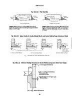
1-7.6 Penetrations Penetrations of the pressure boundary shall comply with the following: (a ) Penetrato rs s hall b e co ns tructed o f material suitable for the intended service and compatible with the vessel shell material. (b) Penetrators shall be either of standard piping components or of a port and insert construction. See Nonmandatory Appendix B, Figures B-2-1 and B-3-1. (c) Where a p enetrato r is o f the p o rt and ins ert construction, the insert shall be constructed of ASME PVHO material. (d) Sealing surfaces of elastomer-sealed penetrators shall be protected from corrosion effects. (e) Penetrators incorporating piping or commercial components shall be rated by the manufacturer to be suitable for the intended design pressure and temperature, and meet the testing requirements of para. 1-7.8. (f) Penetrators and inserts shall be tested in accordance with para. 1-7.8. Portions of the insert that become part of the pressure boundary shall be tested to the same pressure required for the PVHO. Portions of the insert that are subject to greater pressure than the pressure boundary shall be tested in accordance with the requirements of Section 4. (g) Except as permitted in (e), penetrations of the pressure boundary including piping, windows, manways, and service locks shall conform to the reinforcement requirements of ASME BPVC, Section VIII, Division 1 or Division 2. Plate material used as reinforcement shall meet the requirements of ASME BPVC, Section VIII, Division 1, Mandatory Appendix 20 or Section VIII, Division 2, section 3.9.
1-7.2 Welding Pressure vessel welding shall be performed in accordance with ASME BPVC, Section IX.
1-7.3 Nondestructive Testing All nondestructive testing shall conform to ASME BPVC, Section V. (a) All Type No. 1 butt welds shall be 1 00% radiographed. All Type No. 7 corner welds shall be 100% ultrasonically examined. Both the above radiographic and ultrasonic inspections shall be performed in accordance with the specified Division of ASME BPVC, Section VIII. (b) PVHO vessels that incorporate an intermediate head per para. 1-7.1(c) shall be inspected as follows: (1 ) The butt weld joint shall be 100% radiographed and 100% ultrasonic examined per the requirements of ASME BPVC, Section VIII, Division 1 or Division 2. (2) The butt weld, fillet weld, and/or seal weld shall be examined after hydrostatic test in accordance with (d). (c) The reverse side of the root pass of double-welded j oints shall be sound. This shall be shown by magnetic particle (MT) or liquid penetrant (PT) examination. If necessary, chipping, grinding, or melting-out may be required to ensure sound metal. Weld metal shall then be applied from the reverse side. (d) After hydrostatic tests, all pressure-retaining welds and/or seal welds shall be examined in accordance with the requirements for either MT examination (ASME BPVC, Section V, Article 7) or PT testing (ASME BPVC, Section V, Article 6) . The acceptance criteria shall be those of the applicable requirements of the specified Division of ASME BPVC, Section VIII.
1-7.7 Inspection All PVHOs and processes used in their manufacture shall be inspected in accordance with the manufacturer’s quality assurance system, in accordance with Section 3.
1-7.8 Testing All PVH O s and p ressure-retaining co mp onents of PVHOs shall demonstrate structural integrity through testing as follows: (a) All internally pressurized vessels shall be tested according to the applicable Section of this Standard and/or the specified Division of ASME BPVC, Section VIII. (b) Unless otherwise stated in this Standard, all externally pressurized vessels, regardless of the design rules used, shall be subjected to an external pressure test to
1-7.4 Electrical Outfitting Al l e l e ctri ca l p e n e trato rs th ro u gh th e p re s s u re b o undary s hall b e s uitab le fo r the enviro nment in which they will operate in order to minimize the risk o f fire, exp lo s io n, electric s ho ck, emis s io n o f to xic fumes to personnel, and galvanic action on the pressure boundary. 3
ð 19 Þ
ASME PVHO-1–2019
1-7.10 Piping
a differential pressure not less than 1 . 2 5 times the maximum allowable working pressure (MAWP) . The test pressure shall be maintained for not less than 1 hr. The differential test pressure may be achieved by a combination of internal and external test pressures. (c) For hydrotest of vacuum only, or altitude (hypob ari c) ch am b e rs , p e r AS M E B P VC (2 0 1 7 E d i ti o n ) , Section VIII, Division 1, UG-99(f), a vacuum test of 1.25 times the maximum allowable altitude shall be conducted and maintained for a minimum of 1 hr, provided the following tests have been performed: (1 ) The pressure vessel shall be tested in accordance with ASME BPVC (2017 Edition), Section VIII, Division 1, UG-99(f). (2 ) W i n d o w s s h a l l b e t e s t e d a c c o r d i n g t o subsection 2-7. ð 19 Þ
Unless otherwise permitted within this Standard, piping shall conform to the requirements of Section 4 of this Standard.
1-7.11 Opening Reinforcements All opening reinforcements shall be integral with the n o z z l e a n d / o r s h e l l . Re i n fo rc e m e n t p a d s a re n o t permitted.
1-7.12 Brazed or Riveted Construction Brazed or riveted construction is prohibited on the pressure boundary.
1-7.13 Alternative Design Rules for External Pressure Vessels
1-7.9 Documentation
1-7.13.1 General. This subsection provides alternative rules to those given in ASME BPVC, Section VIII, Division 1 or Division 2 for determining allowable compressive stresses and associated allowable external pressure for unstiffened and ring-stiffened circular cylinders, and th e m i n i m u m re q u i re d th i c kn e s s fo r u n s ti ffe n e d spheres and spherical and ellipsoidal heads. The use of these alternative rules may result in a pressure vessel design that is lighter weight than that using the rules of ASME BPVC, Section VIII, Division 1 or Division 2 . When used, this subsection shall be made applicable to the entire vessel. The hull design shall consider all load conditions in addition to external pressure loadings. These load conditions shall include, but are not limited to, those specified in ASME BPVC, Section VIII, Division 1 or Division 2. The cylinder geometry is illustrated in Figure 1-7.13.1-1 and the stiffener geometries in Figure 1-7.1 3.1 -2 . The e ffe cti ve s e cti o ns fo r ri ng s ti ffe ne rs are s h o wn i n Figure 1-7.13.1-3. Use of these rules requires the shell section to be axisymmetric. E xcept for local reinforcement, these rules are based on a uniform thickness of the shell section. Where locally thickened shell sections exist, the thinnest uniform thickness in the adj acent shell section shall be used. The reinforcement for openings in vessels that do not exceed 10% ofthe cylinder or head diameter or 80% ofthe ring spacing into which the opening is placed may be designed in accordance with the requirements of ASME BPVC, Section VIII, Division 1, UG-37(d) (1) or Division 2, 4.5.17 for openings in cylindrical shells and Division 2, 4.5.10 and 4.5.11, as applicable, for openings in spherical and formed heads. The required thickness shall be determined in accordance with para. 1-7.13.4. The factor, F, used in ASME BPVC, Section VIII, Division 1, UG-37(c) shall be 1.0. Openings in shells that exceed these limitations require a special design based on a finite element
The manufacturer (PVHO) shall provide the owner/ user or his/her designated agent a copy of the Manufacturer’s Data Report [PVHO-1 Form GR-1 (PVHO-1 Form GR-1S)] and Forms U-1 and U-2 (Division 1) or Forms A-1 and A-2 (Division 2) , as applicable, for PVHOs built to ASME BPVC, Section VI II . The manufacturer (PVHO) shall retain a copy of the Manufacturer’s Data Report (PVHO-1 Form GR-1 ) ; applicable ASME BPVC, Section VIII forms; and all viewport-supporting documents per Section 2 on file for at least 10 yr from the date of manufacture. Nondestructive testing documentation shall meet the requirements of ASME BPVC, Section V. In addition to the aforementioned documentation, the manufacturer (PVHO) shall furnish the following documentation to the user or his/her designated agent: (a) instructions critical to the maintenance ofthe PVHO (b) instructions critical to the operation of the PVHO and subsystems (operating procedures) (c) coating/painting information (d) photocopy or equivalent of the PVHO data plate (e) list of standards used (f) seal and gasket sizes and materials (g) User’s Design Specification (h ) e vi de nce o f s ucce s s ful co mp l e ti o n o f te s t(s ) required in para. 1-7.8 (i) system schematics (life support, hydraulics, electrical, communications, etc.) (j) system descriptions (life support, hydraulics, electrical, communications, etc.) (k) assembly drawings, including viewport assembly drawings that provide the general dimensions, seat and seal configuration, and retainer ring and fastener details (l) equipment documentation (technical manuals, catalog cuts, etc.)
4
ASME PVHO-1–2019
analysis of the opening and surrounding shell and stiffeners. The required thickness of the reinforcement shall be sufficient to reduce the von Mises stress at the edge of the reinforcement to the von Mises stress in a region distant from the reinforcement. This distant region is typically at unpenetrated regions of a spherical shell, unstiffened cylindrical shell, or midbay in stiffened cylinders. If the von Mises stress at the edge of the reinforcement exceeds that at the distant region, the allowable external pressure shall be decreased by the ratio of the distant region stress to reinforcement edge stress. For stiffened cylinders, special consideration shall be given to ends of members (shell sections) as follows: the von M ises stress at midbay at the end segment shall not exceed 105% of the midbay stress away from the effects of the end. Special consideration shall also be given to areas of load application where stress distribution may be nonlinear and localized stresses may exceed those predicted by linear theory. When the localized stresses extend over a distance equal to one-half the buckling mode (approximately 1 .2 Do t ), the localized stresses should be considered as a uniform stress around the full circumference. Additional stiffening may be required. All calculations shall be performed using all dimensions in the corroded condition.
Fha
Fhe
Fh ef
Fy
FS h1
h2 I IF Is Is′
1-7.13.2 N omenclature
A1 A2 AF AS C
c Do E
e ex
= cross-sectional area of small ring plus shell area equal to L st, in. 2 = cross-sectional area of large ring plus shell area equal to L st, in. 2 = cross-sectional area of a large ring stiffener that acts as a bulkhead, in. 2 = cross-sectional area of a ring stiffener, in. 2 = a factor used to determine minimum shell thickness and length of the template used in checking local shell deviations = distance from neutral axis of cross section to point under consideration, in. = outside diameter of cylinder, in. = modulus of elasticity of material at design temperature, determined from the applicable material chart in ASME BPVC, Section II, Part D, Subpart 2, ksi. The applicable material chart is given in ASME BPVC, Section II, Part D, Subpart 1, Tables 1A and 1B, Tables 2A and 2B, or Tables 5A and 5B. Use linear interpolation for intermediate temperatures. = maximum plus or minus deviation from a true circular form, in. = l o c a l d e vi a ti o n fr o m a s tr a i gh t l i n e measured along a meridian over a gauge length, L x, in.
= allowable hoop compressive membrane s tr e s s o f a c yl i n d e r o r fo r m e d h e a d under external pressure alone, ksi = e l a s ti c h o o p c o m p re s s i ve m e m b ra n e fai lure s tres s o f a cylinder o r fo rmed head under external pressure alone, ksi = a ve r a ge va l u e o f th e h o o p b u c kl i n g stresses, Fh e, over length L F, where Fh e is determined from para. 1-7.13.4(c), ksi = yield strength of material at design metal temperature from applicable table in ASME BPVC, Section II, Part D, Subpart 1, ksi = stress reduction factor or design factor = the full width of a flat bar stiffener or outstanding leg of an angle stiffener, or one-half of the full width of the flange of a tee stiffener, in. = the full depth ofa tee section or full width of an angle leg, in. = moment of inertia of full cross section = πR3 t, in. 4 = moment ofinertia oflarge ring that acts as a bulkhead about its centroidal axis, in. 4 = moment of inertia of ring stiffener about its centroidal axis, in. 4 = moment of inertia of ring stiffener plus effective length of shell about centroidal axis of combined section, in. 4 =
L, L 1 , L 2 , L 3 , L. . .
L B, L B1 ,
Is
+
[
2 As Zs Le t /( A s
+ Le t) ] + Let 3/1 2
= design length of unstiffened vessel section between lines of sup port, in. A line of support is (a ) a circumferential line on a head (excluding conical heads) at one-third th e d e p th o f th e h e ad fro m th e h e ad tangent line as shown in Figure 1-7.13.1-1 (b) a stiffening ring that meets the requirements for Is′ in para. 1-7.13.4(d)
= length of cylinder between bulkheads or large rings designed to act as bulkheads, in. L c = chord length of template used to measure deviation from nominal circularity, in. L e = e ffe c t i v e l e n g t h o f s h e l l , i n . ( s e e Figure 1 -7.1 3 .1 -3 ) . For small ring, L e = 1.1(Do t) 1/2 . For large ring acting as a bulkhead, L e = 1.1(Do t) 1/2 (A 1 / A 2 ). L F = one-half of the sum of the distances, L B, from the centerline of a large ring to the next large ring or head line of support on either side of the large ring, in. (see Figure 1-7.13.1-1)
L B 2 , L B…
5
ASME PVHO-1–2019
1-7.13.4 Stiffened and Unstiffened Cylinders
= one-half of the sum of the distances from the centerline ofa stiffening ring to the next line of support on either side of the ring, measured parallel to the axis of the cylinder, in. A line of support is described in the definition for L (see Figure 1-7.13.1-1), in. L t = o ve ral l l e n gth o f ve s s e l a s s h o wn i n Figure 1-7.13.1-1, in. L x = gauge length measured along meridian of cylinder, in. ML = L / R t F o Ls
Mx P Pa PT R Rc
Ro t t1 t2 Zc
Zs
(a ) Lim ita tio n s . For PVH Os not conforming to the following limitations, the external pressure design shall be as required by the specified Division of ASME BPVC, Section VIII. (1 ) The minimum outside diameter to thickness ratio (Do /t) is restricted to 1,000. (2) The maximum shell thickness, including corrosion allowance, shall not exceed 2 in. (50 mm). (3) The minimum shell thickness, excluding corrosion allowance, shall not be less than 3 ∕8 in. (10 mm). (b) Stress Reduction Factors. The allowable stress is determined by applying a stress reduction factor, FS, to the predicted elastic buckling stress, Fic. The required values of FS are 2.0 when the buckling stress is elastic and 5 ∕3 when the buckling stress equals yield stress at design temperature. A linear variation is used between these limits. The equations for FS are as follows:
= L / Rot = external design pressure, ksi = allowable external pressure in the absence of other loads, ksi = external test pressure, equal to 1.25 P, ksi = radius to centerline of shell, in. = radius to centroid of combined ring stiffener and effective length of shell, in. = R + Zc = radius to outside of shell, in. = thickness ofshell, less corrosion allowance, in. = thickness ofthe bar, leg ofangle, or flange of tee of stiffener, in. = thickness of the web or angle leg of stiffener, in. = radial distance from centerline of shell to centroid of combined section of ring and effective length of shell, in. = A sZs /(A s + L et) = radial distance from centerline of shell to centroid of ring stiffener (p ositive for outside rings), in.
FS = 2.0 if Fic
= =
2.407
0.55 Fy
0.741 Fic / Fy if 0.55 Fy
1 .667 if Fic
Fy
< Fic < Fy
Note that Fic is the predicted buckling stress that is calculated using FS = 1 in the allowable stress equations in (c). (c) Allowable Stress an d Extern al Pressure for Cylin drical Sh ells .
The allowable external pressure in the absence of other loads, Pa , calculated using these rules shall be greater than or equal to the external design pressure, P, i.e., Pa ≥ P. The allowable external pressure for stiffened and unstiffened cylindrical shells is given by the following equation: Pa = minimum of P1 and P2 where P1 = 2 Fha (t/ D o ) P2 = 1.067 Fy(t/ D o )
1-7.13.3 Materials (a) Allowable Materials. Pressure vessels subjected to external pressure may be fabricated from steel materials, with exceptions as noted, listed in ASME BPVC, Section VIII, Division 1 , Tables UCS-2 3 , UHA-2 3 , and UHT-2 3 or Division 2, Tables 3.A.1 through 3.A.3. Materials not acceptable for use for pressure parts are identified in subsection 1-6. General requirements for materials are listed in subsection 1-6. (b) Postweld Heat Treatm en t (PWHT) Requirem ents. The fabricated vessel shall be postweld heat treated in acco rdance wi th th e re qui re me nts o f AS M E B P VC , Section VIII, Parts UCS, UHA, and UHT for a Division 1 design or paras. 6.4 and 6.6 of the ASME BPVC for a Division 2 design. In addition, spherical shells and spherical segment heads shall be postweld heat treated regardless of thickness. The PWHT shall be done prior to the external pressure test.
The allowable external pressure is based on a circumferential compressive stress that is the lesser of Fha and 2 ∕3 Fy at a hydrostatic test pressure of 1.25 P, where Fha = Fy/ FS if Fhe/ Fy ≥ 2.439 = (0.7 Fy/ FS) (Fhe/ Fy) 0.4 if 0.552 < Fhe/ Fy < 2.439 = Fhe/ FS if Fhe/ Fy ≤ 0.552 and where 0.94 Ch = 0.55( t/ D o ) if Mx ≥ 2( D o / t) −1.058 = 1.12 Mx if 13 < Mx < 2(Do/ t) 0.94 = 0.92 / (Mx − 0.579) if 1.5 < Mx ≤ 13 = 1.0 if Mx ≤ 1.5 Fhe = 1.6 Ch E(t/ D o ) (d) Sizing of Stiffener Rings (1 ) Small Rings
6
ASME PVHO-1–2019
2
1 .5 FheLsR c t / E( n
Is
2
and
1)
2
where Fhe is the stress determined from (c) with Mx = Ms n
2
= 2Do 3 / 2 /3 LB t1 / 2
(2) Large Ring Acting as a Bulkhead 2 Fhef LF R c t /2 E
where Fhef is Fhe, which is the stress determined from (c) with Mx = ML . The terms Is, A s, and Zs in the equation for Is′ are those associated with the large ring geometry, such as IF and A F. (3 ) Stiffen er Ge o m e try Req u irem en ts . S ti ffe ne r g e o m e t r y r e q u i r e m e n t s a r e a s fo l l o w s . S e e Figure 1-7.13.1-2 for stiffener geometry and definition of terms. (-a) Flat bar stiffener, flange of a tee stiffener, and outstanding leg of an angle stiffener h1 / t1
0.375
( E / Fy)
= 25 t across circumferential welds < 95% of the meridional distance between circumferential welds.
Lx
1 /2
1-7.13.5 Minimum Required Thickness for Unstiffened Spheres and Formed Heads
(-b) Web of a tee stiffener or leg of an angle stiffener attached to the shell
h2 / t2
1 .0
( E / Fy)
(a) Limitations. The allowable pressure for spheres and spherical segments is derived using the following iterative procedure. This procedure applies to spheres and hemispherical formed heads directly. An adjustment is made for 2:1 ellipsoidal heads. These rules do not apply to other shaped ellipsoidal or to torispherical heads. For PVHOs not conforming to these and the following limitations, the external pressure design shall be as required by the specified Division of ASME BPVC, Section VIII. (1 ) The maximum outside radius, Ro , shall not exceed 60 in. (1 500 mm). (2) The maximum shell thickness, including corrosion allowance, shall not exceed 2 in. (50 mm). (3) The minimum shell thickness, excluding corrosion allowance, shall not be less than 3 ∕8 in. (10 mm). (b) 2:1 Ellipsoidal Heads. For 2:1 ellipsoidal heads, use the procedure specified in (c) using
1 /2
(e) To lera n ces fo r Cylin drica l Sh ells Su b jected to External Pressure.
Cylindrical shells shall meet the tolerances as specified herein. These tolerance requirements replace some portions of those specified in ASME BPVC, Section VIII, Division 1, UG-80(b) or Division 2, 4.4.4. In place of the maximum deviation requirements specified in ASME BPVC, Section VIII, Division 1, UG-80(b)(2) or Division 2, 4.4.4.1(b), the following requirements apply: (1 ) The maximum plus or minus deviation from a true circular form, e , shall not exceed the value given by the following equation: e
= 0.0165 t( Mx + 3.25)1.069
Ro =
Note that e need not be less than 0.2 t and shall not exceed the lesser of 0.0242 R or 2 t. (2) Measurements to determine e shall be made from a segmental circular template having the design outside radius and placed on the outside of the shell. The chord length, L c, is given by the following equation:
Lc
= 2R sin(
n
=
0.9 Do
(c) Minimum Thickness. The minimum required thickness for the spherical shell or formed head exclusive of corrosion allowance shall be determined by the following procedure: Step 1 . Calculate the value of C from the following two equations: C = the larger of C1 or C2
/2n )
where Ä ÅÅ c ÅÅ ÅÇ
1 .41 ( R / T)
(3) All requirements of ASME BPVC, Section VIII, Division 1, UG-80(a) or Division 2, 4.3.2.1 are applicable. The requirements of ASME BPVC, Section VIII, Division 1, UG-80(b)(3), (b)(6) through (b)(8), and (b)(10) or Division 2, 4.4.4.1(c) and 4.4.4.1(e) through 4.4.4.1(h) remain applicable. (4) The local deviation from a straight line, e x , measured along a meridian over a gauge length, L x , shall not exceed the maximum permissible deviation, ex, given below. ex = 0.002 R L x = 4 ( Rt ) but not greater than L for cylinders
Use n = 2 for n 2 < 4 and n = 10 for n 2 > 100. Is
n
C1 =
ÉÑ d Ñ ÑÖ
( R / T ) / ( L / R ) ÑÑ
C2 =
= 2.28(R/ t) 0.54 ≤ 2.80 0.044 ≤ 0.485 d = 0.38( R/ t) c
7
PT Fy 1 .79 PT E
0.75
ASME PVHO-1–2019
Step 2. Enter the left ordinate of Figure 1-7.13.5-1 with the value of C calculated in Step 1. Move horizontally to an intersection with the solid curve. Extrapolation beyond the upper or lower limit of the curve is prohibited. Wh en val ue s o f C fal l o uts i de th e l i mi ts o f Fi gure 1 -7.1 3 .5 -1 , the design shall follow the rules of ASME BPVC, Section VIII, Division 1 , UG-28(d) or Division 2, 4.4.7. Step 3. From the intersection obtained in Step 2 , move vertically down and read the required minimum ratio of thickness to outside radius, t/ Ro . This required minimum ratio applies to the spherical shell for the chosen material yield strength, elastic modulus, and test pressure. Step 4. Determine the minimum required thickness, t, for the given outside radius, Ro . The value of t shall be neither less than 3 ∕8 in. (10 mm) nor greater than 2 in. (50 mm) . If the maximum thickness of the spherical shell including corrosion allowance exceeds 2 in. (50 mm) , th e ru l e s o f AS M E B P VC , S e cti o n VI I I , D i vi s i o n 1 , UG-28(d) or Division 2, 4.4 shall apply.
PT, not less than 1.25 P, to be marked on the vessel. The test
pressure shall be maintained for no less than 1 hr. (b) Post-Test Measurements. Measurements for determining the deviations specified in paras. 1 -7.1 3 .4(e) and 1-7.13.5(d) shall be taken after the external pressure hydrostatic test. Any deviations exceeding the limits ofparas. 1-7.13.4(e) and 1-7.13.5(d) shall be corrected, and the external pressure test shall be repeated. (c) Strain Gauging . As part ofthe hydrostatic test, strain gauges shall be applied to the pressure hull. Gauges shall be applied at hard spots, discontinuities, high-stress regions, and other locations deemed appropriate. Appropriate strain gauge types (single gauge or biaxial/triaxial strain gauge rosettes) shall be used at each location. A drawing(s) shall be created indicating the locations of the gauges on the pressure hull. At the conclusion of the test, a hydrostatic test report shall be created. This report shall include strain gauge locations, strain gauge type at each location, the criteria used to select the strain gauge locations, and the measured stress results. The test report shall also include a comparison of calculated and measured stresses, and an evaluation of any significant differences b etween thes e stres ses . The strain gauge plan and copies of the test report shall be provided to the user and any authorities having jurisdiction.
(d) To lera n ces fo r Sp h erica l Sh ells a n d Sp h erica l Segments Subjected to External Pressure (1 ) Out-of-Roun dn ess. The difference between the maximum and minimum inside diameters at any cross section shall not exceed 1% ofthe nominal inside diameter at the cross section under consideration. The diameters may be measured on the inside or outside of the sphere. If measured on the outside, the diameters shall be corrected for the plate thickness at the cross section under consideratio n. When the cros s s ectio n p as s es thro ugh an o p e n i n g, th e p e rm i s s i b l e d i ffe re n ce i n th e i n s i d e diameters j ust given may be increased by 2 % of the inside diameter of the opening. (2) Local Sh ell Toleran ces. The maximum plus or minus deviations from true spherical form, measured radially on the outside or inside of the vessel, shall not exceed 0.5% of the nominal outside radius of the spherical shell and shall not be abrupt. Measurements shall be made from a segmental template having the design inside or outside radius (depending on where the measurements are taken) and a cho rd length, L C, equal to the arc l e ngth d e te rm i ne d as fo l l o ws : U s i ng th e re q ui re d minimum ratio of thickness to the outside radius, t/ Ro , o b ta i n e d i n S te p 3 , m o ve ve r ti c a l l y u p wa r d o n Figure 1-7.13.5-1 to the intersection of the dashed line. Move horizontally to the right from the dashed line and determine the ratio of critical arc length to outside radius, L c/ Ro . The chord length, L c, is obtained by multiplying this ratio by the outside radius, Ro .
1-7.14 Hatch Design Hatches that do not use bolts for attachment may be designed in accordance with the requirements of ASME BPVC, Section VIII, Division 1, Mandatory Appendix 1, 1-6(g) with the following conditions: (a) The circular centerline of the spherically dished head shall pass through the centroid of the flange. (b) The connection ofthe dished head to the flange shall include fillet(s) of radius not less than 10 mm. (c) If an O-ring seal is specified, it shall be located at the mean radius of the flange. (d) Hatch construction shall be from materials that meet ASME PVHO requirements. (e) If the hatch is convex to pressure, the minimum thickness of the head shall be the greater of that determined in ASME BPVC, Section VIII, Division 1, Mandatory Appendix 1, 1-6(g) and that calculated from para. 1-7.13. (f) The design of doors and hatches shall have a safety interlock system if pressure acts to open or unseat the door or hatch. The safety interlock system shall not permit pressurization of the door or hatch unless the door/hatch closure is fully engaged.
1-7.13.6 Pressure Testing for Alternative Design Ru les. A l l ve s s e l s d e s i gn e d i n a c c o r d a n c e wi th
1-7.15 Rectangular Door Design
para. 1-7.13 shall be tested using the following methods: (a ) Te st Pre ssu re . T h e p re s s u re ve s s e l s h a l l b e subj ected to an external hydrostatic pressure test that subjects every part of the vessel to an external pressure,
If rectangular openings are employed in ASME BPVC, Section VIII, Division 1 or Division 2 construction, a detailed analysis of the interaction of the entire assembly (i.e. , do o r, do o r frame, adj acent s hell, and relative 8
ð 19 Þ
ASME PVHO-1–2019
appurtenances) shall be performed to ensure the design is adequate for the intended application. For Division 2 vessels, the analysis shall be performed in accordance with ASME BPVC, Section VIII, Division 2, Part 5. For Division 1 vessels, see ASME BPVC, Section VIII, Division 1, U-2(g).
(1 ) The required marking on the nameplate shall be in characters not less than 5 ∕32 in. (4.0 mm) high, except the lettering “PVHO-1” shall not be less than 3 ∕8 in. (9.5 mm) high and shall be legible. (2) Characters for metallic nameplates shall be either indented or raised at least 0.004 in. (0.10 mm). (d) The nameplate may be marked before it is affixed to the vessel, in which case the manufacturer shall ensure that the nameplate with the correct marking has been applied to the proper vessel. (e) The nameplate shall be permanently attached to the vessel or to a pad, bracket, or structure that is welded or soldered directly to the vessel. The nameplate shall be located within 3 0 in. (76 cm) of the vessel. Removal shall require willful destruction of the nameplate or its attachment system. (f) In addition to the requirements of (a) through (d), the applicable stamping requirement of the specified Division of ASME BPVC, Section VIII shall be met.
1-7.16 Supports and Attachments Consideration shall be given to the following: (a) The design shall consider the external local forces transmitted to the PVHO. (b) Only those materials permitted for shells may be used for welded lifting attachments, and the material shall be compatible with that of the shell.
1-8 PRESSURE RELIEF DEVICES Unless otherwise specified, the following requirements shall be met for pressure reliefdevices installed on PVHOs. (a ) The ap p li cab le requirements o f AS M E B P VC , Section VI I I , D ivision 1 , UG-1 2 5 through UG-1 3 6 or Section VIII, Division 2, Part 9 shall be met. (b) A quick-operating manual shutoff valve shall be installed between the PVH O and the pressure relief valve, and shall be normally sealed open with a frangible seal as permitted in ASME BPVC, Section VIII, Division 1, UG-135(e) and Nonmandatory Appendix M, and Division 2, Annex 9.A. The valve shall be readily accessible to the attendant monitoring the operation of the PVHO. (c) Rupture disks shall not be used, except in series up s tre am o f p re s s ure re l i e f val ve s to p re ve nt gas leakage, and shall meet all other applicable requirements of the ASME BPVC.
1-10 NONMETALLIC MATERIALS AND TOXICITY OFF-GAS TESTING (a ) A l l n o n m e ta l l i c m a te r i a l s o ff- g a s vo l a ti l e substances that may be toxic. The rate of off-gassing increases with increasing temperature and decreases with increasing age of the material (e.g., plastics and paint). (b) In PVHOs whose primary means of life support is by ventilation ofthe atmosphere and/or by mask supply from an external gas source, off-gassed volatiles are continuously removed and are normally not of consequence, such that the procedures in (d) need not apply. (c) In PVHOs where the primary means oflife support is by addition of oxygen and removal of carbon dioxide (CO 2 ) , off-gassed volatiles will accumulate. Thus, after fabrication and completion of all outfitting, the toxicity off-gas test procedures in (d) are required of any such PVHO that has internal paint or contains nonmetallic materials (other than acrylic windows). (d) Toxicity Off-Gas Testing Procedures (1 ) Internally pressurized PVHOs should be pressurized to MAWP at least once and then thoroughly ventilated prior to doing the off-gas testing. (2) Where the normal duration of PVHO occupation is less than 8 hr, the PVHO shall be sealed and maintained at maximum operating temperature for at least 8 hr, after which time atmospheric gas samples shall be obtained from inside the PVHO and analyzed. The off-gassing test shall be performed with all openings sealed and wi th th e P VH O a t 1 a tm (n o m i n a l ) , re gard l e s s o f MAWP. However, a slight pressurization of the PVHO (prior to closing or sealing) may be used to aid in obtaining gas samples.
1-9 MARKING Each PVHO shall be marked with the following: designation of this Standard, PVHO-1 (2) name of the manufacturer of the pressure vessel, preceded by the words “Certified by” (3) maximum allowable working pressure, psig ( M P a ga u ge ) ( i n te rn a l ) a n d / o r p s i g ( M P a ga u ge ) (external) at °F (°C) maximum and °F (°C) minimum (4) manufacturer’s serial number (5) year built (6) design criteria: PVHO-1–2019; Section(s) (e.g., 5, 6, or 7 as applicable) (b) The marking described in para. 1-9(a) shall be on a nameplate substantially as shown in either Figure 1-9-1 or Figure 1-9-2, as applicable. It shall be of material suitable for the intended service and remain legible for the life of the vessel. Nameplates shall be located in a conspicuous place on the vessel. (c) N amep lates shall have markings produced by casting, etching, embossing, debossing, stamping, or engraving, except that the “PVHO-1 ” lettering shall be stamped on the nameplate. (a)
(1 )
9
ASME PVHO-1–2019
(3) The gas sample shall be analyzed using appropriate gas chromatography/mass spectrometry (GC/ M S ) m e th o d s . T h e co n c e n tra ti o n l e ve l o f vo l a ti l e compounds shall not exceed the threshold limit values (TLVs) set forth in the current edition of ACGIH Threshold Limit Values for Chemical Substances or the OSHA permissible exposure limits (PELs) set forth in 29 CFR 1910.1000, as stip ulated by the user. I f any of those limits are exceeded, the PVHO shall be well ventilated with clean air, and the procedure shall be repeated until satisfactory results are obtained. (4) The use of higher temperatures and/or longer durations to “bake out” sources of contaminants prior to tes ti ng i s p e rmitte d. C are s hal l b e take n no t to exceed the design temperature of components including acrylic windows. (5) Where normal durations of PVHO occupation exceed 8 hr, the previous procedures apply with the exception that the PVHO shall be sealed and maintained at m a xi m u m o p e ra ti n g te m p e ra tu re fo r a t l e a s t th e maximum duration of exposure anticipated. The ACGIH TLVs (or OSHA PEL values) used for evaluation shall be modified by multiplying them by a value of Fp as shown in Table 1-10-1 (linear interpolation is permitted). (6) Where normal durations of PVHO occupation exceed 24 hr, the duration of off-gas may be less, provided that the quantification and reporting limits are less than the allowable limits divided by the ratio of occupation duratio n divi ded b y tes t duratio n. And the res ul ts obtained would then be extrapolated by multiplying by the same ratio ofoccupation duration divided by test duration. For example, in the case of “screening” [see (10)] , if the anticipated occupation duration is 5 days, the off-gas duration may be limited to 24 hr, with the results multiplied by 5, provided that the quantification and reporting limits were less than 5 parts per million (ppm) (vs. 25 ppm allowed) for total hydrocarbons and 2 ppm (vs. 10 ppm allowed) for total halogens. However, if the extrapolated results (after multiplying by 5) exceeded 25 ppm and/or 10 ppm, respectively, then the quantity of gas sample for GC/MS analysis would need to be sufficient to provide quantificatio n and rep o rting limits o f 2 0 p arts p er billion (ppb) (vs. 0.1 ppm). And if that were not practical, then the time ratio used in the testing would need to be appropriately less. (7) For PVHOs that use hydroxide absorbents (e.g., LiOH, soda lime) for the removal of carbon dioxide (CO 2 ), the co ncentratio ns o f trichlo ro ethylene, vinylidene chloride, methyl chloroform, and acetylene dichloride shall not exceed 0 .1 ppm, regardless of their ACGIH TLV (o r O S H A PE L) o r duratio n o f o ccup atio n; i. e. , Table 1-10-1 does not apply to those four compounds. (8) Where reactive co mp ounds (e. g., ammonia, chlorine, hydrogen sulfide, sulfur dioxide) are anticipated, on-site testing for the presence of these compounds should be done using appropriate color-change indicator
tubes (e.g., Draeger, Gastec). Evaluation of the test results shall be in accordance with (3), (5), or (6), as applicable. (9) Where potential sources of mercury vapor are anticipated, on-site testing for its presence should be done using either color-change indicator tubes with a s ufficiently lo w detectio n limit o r a go ld- film- typ e analyzer. Evaluation of test results shall be in accordance with (3), (5), or (6), as applicable. (1 0) If the total halogen concentration can be shown to be less than 1 0 ppm, and the total hydrocarbons (expressed as methane) can be shown to be less than 25 ppm, then the GC/MS analysis and evaluation need not be done. However, if either of those limits is exceeded, the GC/MS analysis and evaluation are required.
1-11 RISK ANALYSIS The PVHO designer shall implement and document an established standard or procedure (such as a failuremodes , effects , and criticality analys is o r a s afetyhazards analysis) for evaluating and mitigating potential risks associated with the PVHO and associated systems. Potential hazards shall include both hardware failure and operator error. The risks identified shall be evaluated and mitigated to a level acceptable by the user or appropriate autho rity. M itigation and p ro tective measures may include design features that minimize the probability of occurrence, inspection and tests during and following fabrication, implementation of safety and/or warning devices, protective systems, and caution or warning procedures and labels. The risk analysis results shall be retained by the designer in accordance with para. 1-7.9.
1-12 LITHIUM BATTERIES 1-12.1 Scope The requirements of this subsection apply to rechargeable and nonrechargeable lithium batteries that are used as the main or emergency source of power for the PVHO. These include, but are not limited to, lithium ion, lithium alloy, lithium metal, and lithium polymer type batteries, or other lithium battery chemistries that have the potential for self-sustaining energy release.
1-12.2 Exclusions Lithium batteries used for portable equipment, e.g., laptops, cell phones, cameras, or other portable equipment, are not included under the scope of these requirements.
1-12.3 Certification Lithium batteries shall be certified by a third-party independent agency, e.g., Underwriters Laboratories (UL) o r C anadi an S tandards As s o ci ati o n (C S A) , as
10
ð 19 Þ
ASME PVHO-1–2019
complying with the requirements of one of the following standards: (a) Section 38.3, UN Manual of Tests and Criteria (b ) U L 1 6 4 2 , U L S tandard fo r S afe ty o f Li th i um Batteries (c) other equivalent recognized national or international standards for lithium batteries
(3) Water intrusion sensors, fire detectors, and pressure and temperature sensors, as appropriate, shall be provided within the housings. These devices shall activate audiovisual alarms in order to alert the PVHO operator of an adverse event (e.g., a fire or water leakage) within the housing. (4) When the battery housings are contiguous with the pressure boundary of the PVHO, these housings shall meet the “A60” structural fire protection rating as defined by the IMO International Code for Application of Fire Test Procedures (FTP Code) , or equivalent recognized standards.
1-12.4 Installation (a) Unless otherwise permitted by the jurisdictional authority, lithium batteries shall be installed outside the occupied pressure boundary of the PVHO. (b) All installations shall include appropriate means to prevent inadvertent shorting between the terminals of lithium batteries (e.g., nonshorting caps). (c) Prior to installation, a risk analysis shall be carried out for evaluating and mitigating potential risks associated with the lithium battery installation, as well as the normal and emergency operating procedures.
1-12.6 Battery Management System (BMS) for Rechargeable Batteries Rechargeable lithium battery installations shall be provided with an electronic BMS. (a) The BMS shall provide means for (1 ) monitoring the state of charge and state of health of the batteries (2) charge control to prevent overcharging/undercharging and voltage reversal (3) discharge control to prevent overdischarging (4) intermodule and intramodule balancing of the cells (5) overcurrent (short circuit) protection to prevent overcurrent discharge (b ) The BMS shall provide real-time performance monitoring of the following parameters: (1 ) voltages (cell level and module level) (2) currents (cell level and module level) (3) state of charge and state of health (module level) (4) temperature (module level) (c) Appropriate sensors and audiovisual alarms shall be provided to alert the PVHO operator when the parameters in (b) are outside their allowable limits.
1-12.5 Battery Housings Lithium batteries may be installed in either a 1-atm housing or a pressure-compensated housing. (a) Gen eral Requirem en ts . All battery installations ho us ing lithium b atteri es s hall meet the fo llo wi ng general requirements: (1 ) The housings shall be installed in locations that are as far away as practicable from sources of heat, compressed gas cylinders, and acrylic windows on PVHOs. (2) The housings shall be mechanically protected from direct impact loads. For PVHOs that are transported while in service (e.g., diving bells or submersibles) , the battery housing shall also be protected from acceleration shock loads. (3) The housings shall be provided with means of p ressure relief (such as blowout plugs or vents) in order to relieve any potential pressure buildup within th e h o u s i n g d u e to m al fu n cti o n i n g b atte ri e s . T h e di s ch arge o f the me ans o f p re s s ure re li e f s h al l b e vented as far away as practicable from sources of heat, compressed gas cylinders, and acrylic windows on PVHOs. (4) All electrical circuits shall be insulated and isolated from the structural elements of the housings. (5) The housings shall be labeled appropriately and shall be provided with appropriate signs warning personnel against inadvertent abuse. (b ) 1 - a tm Ho u sin g s. Wh e n l i th i um b atte ri e s are installed in 1-atm housings, the following additional requirements shall be met: (1 ) The housings shall be designed to permit purging and charging of the internal atmosphere with inert gas, so as to minimize the oxygen concentration below the flammable limit. (2) All of the electrical equipment within the housings shall be of the explosion-proof type.
1-12.7 Protection for Nonrechargeable Batteries Nonrechargeable lithium battery installations shall be provided with the following: (a) over-temperature protection (b) overcurrent (short circuit) protection (c) voltage reversal protection
1-12.8 Testing (a) Lithium batteries exposed to ambient pressures e xcee di ng 1 atm s h al l b e hydro s tati cal l y p res s ure tested prior to being placed in service. The pressure tes ting s hall b e carried o ut to the maximum rated depth of the PVHO. Satisfactory operation of the batteries shall be demonstrated during this pressure testing. (b) For rechargeable batteries, functional testing of the BMS (see para. 1-12.6) shall be carried out.
11
ASME PVHO-1–2019
(c) For nonrechargeable batteries, functional testing of the battery protection devices (see para. 1-12.7) shall be carried out.
software (code) analysis, testing, and validation, with the level of rigor applied being commensurate with the p otential level of risk. The following shall ap p ly to P VH O s th a t e m p l o y s o ftwa r e to m o n i to r a n d / o r control safety-critical systems or functions. The PVHO designer shall implement and document a software safety analysis (including analysis, testing, and validation) that is in accordance with an established standard or procedure. Examples include (but are not limited to) the (DOD) Joint Software Systems Safety Engineering Handbook and (FDA) General Principles of Software Validation: Final Guidance for Industry and Staff. This safety analysis shall be performed by a qualified person other than the software developer, and the results of the software safety analysis, testing, and/or validation shall be retained by the designer in accordance with para. 1-7.9. Additionally, there shall be an independent method of monitoring and manually controlling all life-critical systems. If applicable, the risk analysis should consider ris ks p o tentially as s o ciated with co nnectio n to the Internet and/or third-party data centers.
1-12.9 Charging (a) For rechargeable lithium batteries, the charging procedures shall be documented in the operations and maintenance manuals of the PVHO. (b) As a minimum, the charging procedures shall follow the battery manufacturer’s recommendations and specifications. (c) Charging of lithium batteries shall be carried out while the PVHO is not in service, using the manufacturer-specified battery chargers.
1-12.10 Replacement (a) Lithium batteries (including individual cells) shall be replaced, taking the following into consideration: (1 ) manufacturer’s recommendations and specifications (2) visual inspection (3) deterioration of performance (b) The replacement shall be carried out when the PVHO is not in service.
1-14 OPERATIONAL PRESSURE CYCLE Before a PVHO may be put into service, a registered Professional Engineer, or similar, knowledgeable about the design and intended usage of the PVH O system shall review the User Requirements and all other available design and usage information to assess the need to require tracking of pressure cycles during operation of the PVHO chamber/components/system (e.g., for fatigue analysis, fracture mechanics analysis, and fitness-for-service assessments). If it is determined that tracking of operational pressure cycles is required, a definition(s) for “operational pressure cycle(s) ” shall be provided by a registered Professional Engineer, or similar, knowledgeable about the design and intended usage of the PVHO system. This definition shall include all relevant parameters (e. g. , p ressure, temp erature, and time) that impact the minimum pressure differential that shall be recorded during usage to track available life for the P VH O chamb e r/co mp o ne nt/s ys te m. I t s ho ul d al s o include any threshold conditions beneath which an increase in pressure should not be counted as a pressure cycle. Various components may require their own unique definition of an operational pressure cycle.
1-12.11 Manuals and Records (a) The normal and emergency operating and maintenance procedures for the use of lithium batteries shall be documented in the operations and maintenance manuals of the PVHO. (b) As a minimum, these procedures shall follow the battery manufacturer’s recommendations and specifications. (c) The emergency procedures shall address events such as fires, thermal runaways, short circuits, leaks, hazardous gas buildup, low-temperature charging, electrical shocks, and stored energy hazards, as applicable. (d) Any special measures taken for mitigating or eliminating potential risks [see para. 1-12.4(c)] shall be documented in the operations and/or maintenance manuals. (e) A log shall be maintained to record vital information such as the installation dates and maintenance history of the batteries. ð 19 Þ
1-13 AUTOMATIC CONTROL AND SOFTWARE SAFETY Software risk is a function of the potential severity of mishap in conj unction with the degree of autonomy exerted by the software. The risk mitigation consists of
12
ð 19 Þ
ASME PVHO-1–2019
13
ASME PVHO-1–2019
14
ASME PVHO-1–2019
Figure 1-7.13.1-1 Geometry of Cylinders
15
ASME PVHO-1–2019
Figure 1-7.13.1-2 Stiffener Geometry
Figure 1-7.13.1-3 Sections Through Rings
16
ASME PVHO-1–2019
Figure 1-7.13.5-1 Values of t/Ro and
/
L c Ro
0.1
0.05
0.01
1 .0
0.005
0.5
0.002
0.2
Lc /Ro
C
0.02
0.001 0.003
0.005
0.01
0.02
t/Ro
17
0.05
0.1 0.1
ASME PVHO-1–2019
Figure 1-9-1 Form of Nameplate, U.S. Customary Units
Figure 1-9-2 Form of Nameplate, SI Units
Table 1-10-1 Conversion Factor, Fp (for PVHO Occupation Exceeding 8 hr) Duration of Exposure
Fp
8 hr (or less)
1.0
12 hr
0.85
16 hr
0.75
24 hr
0.65
36 hr
0.56
48 hr
0.52
72 hr
0.46
7 days
0.37
14 days
0.32
30 days
0.28
60 days
0.26
90 days (or longer)
0.25
18
ASME PVHO-1–2019
Section 2 Viewports 2-1 GENERAL
ofthe window throughout all processes associated with its manufacture.
2-1.1 Scope
2-1.3.2 Additional Requirements. In addition to the overall window certification, the following certifications shall be required for a window to be considered acceptable for use in chambers: (a ) a d e s i gn ce rti fi ca ti o n fo r e a ch wi n d o w an d m a tc h i n g vi e wp o rt a s s e m b l y th a t s h a l l i n c l u d e a summary ofengineering calculations and/or a description of the experimental method and data used to verify compliance of the window design with the requirements of this Standard (see subsection 2-2 for design requirements). (b) a material manufacturer’s certification for each lot of acrylic that shall certify that the material meets or exceeds the minimum values of physical properties specified in Table 2-3.4-1 for each lot and verify for each casting or lot (see subsection 2-3 for material certification requirements). (c) a material certification for each window shall certify that the material meets the minimum values specified in Table 2-3.4-2 and that these properties have been experimentally verified. Average values specified in Table 2-3.4-2 shall be reported (see subsection 2-3 for material certification requirements). (d) a pressure testing certification for each window that shall describe the pressure, temperature, pressurization rate, duration of sustained loading, and viewport flange or test fixture used during the p ressure test (see subsection 2-7 for pressure testing requirements).
This Standard covers windows manufactured during original construction and windows used as replacements during the service life of the chamber. The windows covered by this Standard are intended for use only in chambers with window service conditions defined by (a) maximum allowable working pressure, equal to design pressure (b) maximum temperature at design pressure, equal to design temperature (c) pressure cycles, at design pressure and temperature
2-1.2 Exclusions The windows covered by this Standard are not intended for chambers where any of the following restrictions on design parameters are exceeded: (a) The operating temperature shall be within the 0°F to 150°F (−18°C to 66°C) range. (b) The pressurization or depressurization rate shall be less than 145 psi/sec (1 MPa/s). (c) The fluid (external or internal) shall be only water, seawater, air, or gases used in life-support systems. (d) The number of pressure cycles or the total duration of the operational life of the window shall not exceed 10,000 cycles or 40,000 hr, respectively. (e) The maximum op eratio nal p ressure s hall not exceed 20,000 psi (138 MPa). (f) The exposure to nuclear radiation shall not exceed 4 Mrad. (g) The design life of the windows shall not exceed the time limits specified in para. 2-2.7.
2-2 DESIGN 2-2.1 General The manufacturer of the chamber shall be responsible for ensuring that the viewport design is adequate for the design conditions of the chamber. Particular attention shall be paid to design consideration of the window, including, but not limited to, the design pressure, the temperature at design pressure, and the cyclic life at design pressure. An ASME PVHO-1 acrylic window may be assigned more than one pressure–temperature rating, provided (a ) The windo w is in co mp lete co mp liance with Section 2 for each pressure–temperature rating.
2-1.3 Certification Each window shall be individually identified by the window fabricator in accordance with para. 2-6.1.
2-1.3.1 Traceability. The window fabricator shall p ro vide an o ve ral l wi ndo w ce rti fi cati o n th at s hall certify that the window has been fabricated in accordance with all applicable requirements of the Standard (see PVHO-1 Form VP-1 for a representative certification form). The window certification shall provide traceability 19
ð 19 Þ
ASME PVHO-1–2019
2-2.4 Determination ofConversion Factor by Table Method
(b) PVHO-1 Form VP-2 (Acrylic Window Design Certification) must be completed and signed for each pressure– temperature rating. (c) The pressure test shall be performed at the press ure – te mp e rature rati ng th at re qui re s the l arge s t minimum thickness, t (calculated). If the minimum thickness is the same, the pressure test shall be performed at the highest pressure. (d) The window shall be marked in accordance with this Standard for each pressure–temperature rating.
2-2.4.1 Temperature. When selecting the conversion factors from Tables 2-2.3.1-1 through 2-2.3.1-5, temperature ranges shall be chosen on the basis ofhighest ambient sustained temperature expected during operation of the chamber at the design pressure. (a) If the chamber interior is illuminated by externally mounted heat-generating lights shining through the windows, the 150°F (66°C) temperature range shall be mandatory in the selection of conversion factors for all windows. (b) If the chamber is not illuminated with externally m o u n te d l i gh ts , th e te m p e ra tu re ra n ge s s h a l l b e cho sen o n the b as is o f enviro nmental temp erature where the chamb e rs reach de s i gn p res s ure . I f the design pressure is reached when (1 ) o nly s ub merged in water, us e the amb ient temperature of water at that depth (2) only in air, use the average of the maximum ambient external and internal air temperatures (3 ) e i th e r i n ai r o r i n wate r, us e th e ave rage maximum ambient external and internal air temperatures
2-2.2 Standard Window Geometry 2-2.2.1 Configuration. Acrylic windows in chambers must have one of the standard geometries shown in Figures 2-2.2.1-1 through 2-2.2.1-4. Minimum acceptable thickness ratios shall comply with the requirements of Figures 2 - 2 . 2 . 1 -1 through 2 - 2 . 2 . 1 -4 for the s p ecific window geometry. (Fo r accep tance o f no ns tandard window geometries, see para. 2-2.6.) 2-2.2.2 Calculation. Calculations of the short-term c ri ti c a l p re s s u re (S T C P ) , o n th e b a s i s o f F i gu re s 2-2.2.1-1 through 2-2.2.1-4, satisfy the requirements of the de s i gn ce rti fi cati o n re qui re d b y thi s S tandard under para. 2-1.3.2(a).
2-2.4.2 Pressure. When a viewport is subj ected to pressurization from both sides, the conversion factor used for the window design shall be determined on the basis of the highest design pressure, regardless of whether this pressure is external or internal to the chamber.
2-2.2.3 Tests. It shall also be acceptable to establish the
STCP by conducting a series of destructive tests on fullscale or model-scale windows performed in accordance with the procedure in para. 2-2.5.2.
2-2.3 Determination of Dimensions for StandardGeometry Windows
2-2.4.3 Values ofConversion Factors. The values ofCF in Tables 2-2.3.1 -1 through 2 -2 .3.1-5, D i/ D f in Figures 2-2.10.1-1 and 2-2.10.1-2 and Table 2-2.3.2-1, and t/ D i in Table 2 -2 .3 .2 -1 represent minimums. The user of this Standard may exceed these values.
2-2.3.1 0 psi to 10,000 psi. The dimensions of a standard window in the 0 psi to 10,000 psi (0 MPa to 69 MPa) design p res sure range s hall b e b as ed s olely on the window’s STCP and the approved conversion factor (C F) fo r the given maximum amb ient temp erature. Minimum STCP values of standard window geometries are given in Figures 2 -2 .5 .1 -1 through 2 -2 .5 .1 -1 5 . CF values for standard window geometries are given in Tables 2-2.3.1-1 through 2-2.3.1-5.
2-2.5 Determination of Short-Term Critical Pressure 2-2.5.1 Calculation Method. The STCP of a window accepted for service in chambers, without the use of experimental data, shall not be less than STCP = CF
2-2.3.2 10,000 psi to 20,000 psi. The dimensions of windows in the 1 0,000 psi to 2 0,000 psi (69 MPa to 138 MPa) design pressure range shall be based solely on nondestructive tests in the form of long-term and c yc l i c p r e s s u r i z a ti o n s . D i m e n s i o n s o f a p p r o ve d windows for this design pressure range are given in Table 2 -2 .3 .2 -1 . Only conical frustum windows with included angle of 90 deg or larger are qualified for this pressure range.
×P
where CF = conversion factor P = design pressure Windows having included angles between those shown in Figures 2-2.5.1-4 through 2-2.5.1-7 are to have a t/ D i equal to that determined for a window of the next smaller included angle as shown in the appropriate figure. (For example, a spherical sector window having an included angle of 1 00 deg and requiring an STCP in the 5 MPa to 50 MPa range would be designed using the 90-deg curve in Figure 2-2.5.1-6.) 20
ASME PVHO-1–2019
the magnitude of internal design pressure does not exceed 5% of the external design pressure. (i ) F o r N E M O a c r y l i c w i n d o w s , s h o w n i n Figure 2 - 2 . 2 . 1 - 4, us e C Fs fro m Tab le 2 - 2 . 3 . 1 - 3 and STCPs from Figures 2 -2 .5 .1 -1 4 and 2 -2 .5 .1 -1 5 . Shortterm critical pressures may also be experimentally determined acco rding to the p ro cedure in p ara. 2 - 2 . 5 . 2 . Windows of this type are accepted for service where the hydrostatic pressure is applied only to the convex surface, or the hydrostatic pressures are applied to either surface but the magnitude of the internal design pressure does not exceed 5% of the external design pressure.
(a ) F o r fl a t d i s k a c r y l i c w i n d o w s , s h o w n i n Figure 2 -2 .2 .1 -1 , use conversion factors from Table 2 -2 .3 .1 -1 and STCPs from Figures 2 -2 .5 .1 -1 through 2 -2 .5 .1 -3 . Short-term critical pressures may also be experimentally determined according to the procedure in para. 2-2.5.2. (b) For conical frustum acrylic windows, shown in Figure 2 - 2 . 2 . 1 - 1 , us e C Fs fro m Tab le 2 - 2 . 3 . 1 - 2 and STCPs from Figures 2-2.5.1-4 and 2-2.5.1-5. Short-term critical pressures may also be experimentally determined according to the procedure in para. 2-2.5.2. Windows of this type are accepted for service only where the pressure is applied to the base of the frustum. (c) For double-beveled disk acrylic windows, shown in Figure 2-2.2.1-1, use CFs from Table 2-2.3.1-2 and STCPs from Figures 2-2.5.1-4 and 2-2.5.1-5. Short-term critical p re s s ure s may al s o b e exp erimentall y determi ned according to the procedure in para. 2-2.5.2. (d) For spherical sector acrylic windows with conical edge, shown in Figure 2 -2 .2 .1 -2 , use CFs from Table 2 - 2 . 3 . 1 - 3 a n d S T C P s fr o m F i gu r e s 2 - 2 . 5 . 1 - 6 a n d 2 -2 .5 .1 -7. Short-term critical pressures may also be experimentally determined according to the procedure in para. 2-2.5.2 . Windows of this type are accepted for service only where the hydrostatic pressure is applied to the convex face. (e) For spherical sector acrylic windows with square edge, shown in Figure 2 -2 .2 .1 -2 , use CFs from Table 2 - 2 . 3 . 1 - 4 a n d S T C P s fr o m F i gu r e s 2 - 2 . 5 . 1 - 6 a n d 2 -2 .5 .1 -7. Short-term critical pressures may also be experimentally determined according to the procedure in para. 2-2.5.2 . Windows of this type are accepted for service only where the hydrostatic pressure is applied to the convex surface. (f) For hemispherical windows with equatorial flange, shown in Figure 2-2.2.1-3, use CFs from Table 2-2.3.1-4 and STCPs from Figures 2-2.5.1-6 and 2-2.5.1-7. Shortterm critical pressures may also be experimentally determined acco rding to the p ro cedure in p ara. 2 - 2 . 5 . 2 . Windows of this typ e are accep ted for service only wh e re th e h yd ro s ta ti c p re s s u re i s a p p l i e d to th e convex surface. (g ) F o r c yl i n d r i c a l a c ryl i c wi n d o ws , s h o wn i n Figure 2 - 2 . 2 . 1 - 3 , us e C Fs fro m Tab le 2 - 2 . 3 . 1 - 5 and S TC P s fro m F i gu re s 2 - 2 . 5 . 1 - 8 th ro u gh 2 - 2 . 5 . 1 - 1 3 . Short-term critical pressures may also be experimentally determined according to the procedure in para. 2-2.5.2. (h) For hyperhemispherical acrylic windows, shown in Figure 2-2.2.1-4, use CFs from Table 2-2.3.1-3 and STCPs from Figures 2-2.5.1-14 and 2-2.5.1-15. Short-term critical p re s s ure s may al s o b e exp erimentall y determi ned according to the procedure in para. 2 -2 .5.2 . Windows of this type are accepted for service where the hydrostatic pressure is applied only to the convex surface, or the hydrostatic pressures are applied to either surface but
2-2.5.2 Testing Method. The experimental determination ofthe STCP ofan acrylic window shall be conducted by subj ecting the window to hydrostatic pressure that is increased, from ambient, at a constant rate of approximately 650 psi/min (4.5 MPa/min). The pressurization shall take place at the ambient temperature range of 70°F to 77°F (2 1 °C to 2 5 °C) in a flange that satisfies the requirements of para. 2-2.9. The evaluation of a window design shall be conducted on a minimum of five full-scale windows or on a minimum of five model-scale windows plus one full-scale window. (a) For tests conducted on full-scale windows, the results generated shall be considered representative only if the lowest STCP for any window is at least 75% of the mean STCP of the other four windows. In such a case, the STCP value of the window design shall be taken as the lowest critical pressure among the five te s ts . I n the cas e where the lo wes t S TC P do es no t meet this criterio n, the S TC P value o f the windo w design shall be equal to the single lowest STCP among the five windows multiplied by a factor of 0.75. (b) For tests conducted on model-scale windows, the results shall be considered acceptable only if the STCP of the full-scale window is equal to or above the single lowest STCP among the five model-scale windows. In case the STCP of the single full-scale window does not meet this criterion, four more full-scale windows shall be tested, and the STCP value of the window design shall be calculated according to (a) , solely on the basis of the full-scale window tests.
2-2.6 Nonstandard Window Geometries and Standard Window Geometries With Lower Conversion Factors 2-2.6.1 Case Submittal Procedure. Acrylic windows of nonstandard geometry, or of standard geometry but with nonstandard lower CFs, may be submitted for consideration as a Case for adoption by the ASME Pressure Vessels for Human Occupancy Committee and possible subsequent incorporation into the Standard as another standard geometry or standard CF for windows meeting the design parameters of subsection 2-2. 21
ASME PVHO-1–2019
(c) The pressures to which five individual windows shall be subjected are 0.9, 0.8, 0.75, 0.7, and 0.65 times th e a ve r a ge S T C P e s ta b l i s h e d e xp e r i m e n ta l l y i n para. 2-2.6.4. (d) The experimental data points of (c) shall be plotted on log-log coordinates, and the relationship between critical pressures and duration of loading shall be represented empirically by a straight line. The experimental points generated in para. 2-2.6.4 with 30-min sustained loading duration shall be plotted on the same graph. The testing of any window specimen that has not failed in 1 0,000 hr of sustained loading may be terminated at that time and its data point omitted from the graph. (e) The extension of the plotted line to 80,000 hr of sustained loading shall exceed the LTPP. The extrapolated failure at 80,000 hr shall be at least two times the design pressure. (f) An alternative to the LTPP tests defined in (b) through (e) shall be sustained pressure loading of individual windows for a duration of 1 0 ,0 0 0 hr at design temperature per one of the following test programs: (1 ) One window shall be tested at a sustained pressure equal to 0.9 STPP. (2) Two windows shall be tested at a sustained pressure equal to 0.85 STPP. (3) Three windows shall be tested at a sustained pressure equal to 0.8 STPP. (4) Four windows shall be tested at a sustained pressure equal to 0.75 STPP. (5) Five windows shall be tested at a sustained pressure equal to 0.7 STPP. If all windows of any one of the five selected test programs above survive sustained pressurization for 1 0 ,0 0 0 hr without catastrophic failure, the window design is considered to have satisfied fully all requirements of the LTPP test.
(a) Prior to submission for review, the window design shall be experimentally verified according to para. 2-2.6.3, and the window design, testing procedure, test results, and any o ther pertinent analytical o r exp erimental d ata s h al l b e s um mari z e d i n a cl e ar, co nci s e , and legible technical report. (b) One copy of the report shall accompany the submission for consideration by the Committee. Submission of the report to the Committee places its content into the public domain for review and comment by the public.
2-2. 6. 2 U se in Stan d ard PVH Os. Windo ws wi th nonstandard geometries, or with standard geometries and lower CFs, may be incorporated into chambers for human occupancy provided their material properties and s tructural p erfo rmance s atis fy the mandato ry short-term, long-term, and cyclic proof pressure requirements of this Standard. 2-2.6.3 Testing Criteria. Windows with nonstandard geometries, or with standard geometries and lower CFs, shall meet the following mandatory requirements: (a) short-term proofpressure (STPP) : 4 times the design pressure, sustained continuously for a minimum of30 min without catastrophic failure at design temperature environment under short-term pressurization (b) long-term proof pressure ( LTPP): design pressure sustained continuously for 80,000 hr in design temperature environment without catastrophic failure (c) crack-free cyclic proof pressure (CPP) : design pressure sustained intermittently during 1 ,0 0 0 pressure cycles of 8 hr each in design temperature environment without cracking 2-2.6.4 STPP Test Procedure. The STPP of a window with nonstandard geometry, or with standard geometry and lower CF, shall be experimentally verified with a minimum of five windows. The STPP windows tested may consist of any combination of model-scale (of the same size) or full-scale windows. (a) The windows shall be individually pressurized at 650 ± 100 psi/min (4.5 ± 0.7 MPa/min) in the design temperature environment to the STPP. (b) All five windows shall survive the STPP test without catastrophic failure.
2-2.6.6 CPP Test Procedure. The crack-free CPP of the window with nonstandard geometry, or with standard geometry and lower CF, shall be experimentally verified on a minimum of two model-scale windows (of the same size) or a single full-scale window. (a) The window shall be pressure cycled 1,000 times from zero to CPP in the design temperature environment. (b) The length of the individual pressure cycles may vary from one cycle to another, but the average length of the sustained loading and relaxation phases in all of the pressure cycles shall equal or exceed 4 hr. (c) At the completion of 1 ,000 pressure cycles, the window shall be visually inspected with the unaided eye (except for correction necessary to achieve 20/20 vision) for the presence of cracks. (d) Absence of visible cracks shall be considered proof that the window design meets the crack-free CPP requirement of this Standard.
2-2.6.5 LTPP Test Procedure. The LTPP of a window with nonstandard geometry, or with standard geometry and lower CF, shall be experimentally verified as per the following paragraphs, using model-scale (ofthe same size) or full-scale windows: (a) The windows shall be individually subj ected to sustained pressure loading at design temperature. (b) Each window shall be subj ected to a different hydrostatic pressure, and the duration of sustained pressure preceding the catastrophic failure shall be recorded.
22
ASME PVHO-1–2019
2-2.6.7 Test Temperature Criteria. The temperature of the window, the window test assembly, and its pressurizing medium during the performance of proof tests is allowed to deviate from the specified design temperature by the following margin: (a) for the short-term pressurization of para. 2-2.6.4, +10°F (5.5°C) (b) for the long-term pressurization of para. 2-2.6.5, +10°F (5.5°C) (c) for the cyclic pressurization of para. 2-2.6.6, +25°F (14°C)
yr from the date of fabrication for t/ D i < 0.5 and 20 yr for t/ Di ≥ 0.5.
2-2.7.5 Spherical Sector With Conical Edge, Hyperhemisphere With Conical Edge, and NEMO-Type Windows With Conical Edge Penetrations. The design life of sphe-
rical sector with conical edge, hyperhemisphere with conical edge, and N EMO-type windows with conical edge p enetrati o ns s h o wn in Fi gure s 2 - 2 . 2 . 1 - 2 and 2-2.2.1-4 and meeting the requirements of this Standard shall be 20 yr from the date of fabrication.
2-2.7.6 Spherical Sector Windows With Square Edge and Hemispherical Windows with Equatorial Flange. The
2-2.6.8 Fixturing. All STPP, LTPP, and CPP testing shall
be performed with each window mounted securely in a test fixture designed to withstand the maximum test pressure to which the window may be subjected. (a) The window seat dimensions of the test fixture for full-size windows shall be the same as those used for the viewport flanges with operational full-size windows. (b) The window seat dimensions of the test fixture for model-scale windows shall be scaled down from test fixtures for full-size windows.
design life of spherical sector windows with square edge and hemispherical windows with equatorial flange shown in Figures 2-2.2.1-2 and 2-2.2.1-3 and meeting the requirements of this Standard shall be 10 yr from the date of fabrication.
2-2.7.7 Cylindrical Windows for Internal Pressure Applications. The design life of cylindrical windows
fo r i n t e r n a l p r e s s u r e a p p l i c a t i o n s s h o w n i n Figure 2-2.2.1 -3 and meeting the requirements of this Standard shall be 10 yr from the date of fabrication.
2-2.6.9 Scaling. The successful qualification of a window design with nonstandard geometry, or with standard geometry and lower CF, for a chosen design pressure and temperature under the procedures of paras. 2-2.6.2 through 2-2.6.8, qualifies also other window designs with the same geometry and same or higher t/ D 1 ratios for the same or lower design pressure and temperature.
2-2.7.8 Cylindrical Windows for External Pressure Applications. The design life of cylindrical windows
fo r e x t e r n a l p r e s s u r e a p p l i c a t i o n s s h o w n i n Figure 2-2.2.1 -3 and meeting the requirements of this Standard shall be 20 yr from the date of fabrication.
2-2.7.9 Increase in Cyclic Design Life. For standardgeometry PVHO viewports having a design pressure ofless than 2,000 psi (13.8 MPa), other than hyperhemispherical and NEMO types, the number ofdesign pressure cycles can be increased in excess of that stated in PVHO-1 through experimental pressure testing procedures, provided the following procedures and requirements are met: (a) For each window design, at least one window of identi cal s hap e, dimens io ns , and des i gn p res s ure– temperature rating shall be pressure cycled from zero to design pressure to determine whether its cyclic pressure fatigue life exceeds the 10,000 cycle limit stated in PVHO-1 . The pressure tests shall take place with the window installed in a test fixture whose window seat dimensions, retaining ring, and seals are identical to those of the PVHO chamber. (b) The window shall be pressurized with gas or water. The design pressure shall be maintained for a minimum of 15 min, or 1.5 times the time it takes for creep to stabilize, whichever is greater, followed by depressurization that is to be maintained for a minimum of 10 min or 1.5 times the time it takes for creep to stabilize, whichever is greater. The pressurization and depressurization rates shall not exceed 650 psi/min (4.5 MPa/min). (c) The temp erature of the p ressurizing medium during the test shall be the design temp erature for which the window is rated with a tolerance of +0/−5°F
2-2.7 Design Life 2-2.7.1 General. The design life of a window is a function of its geometry, conversion factor, t/ D i ratio, and service enviro nment. Windows that are exp osed to only compressive or very low tensile stresses have a longer design life than those that are exposed to high tensile stresses. The design life of windows in the first category shall be 2 0 yr, while for the windows in the latter catego ry it s hall b e 1 0 yr. The des ign life o f w i n d o w s u n d e r t h i s S t a n d a r d i s d e fi n e d i n paras. 2-2.7.2 through 2-2.7.8. 2-2.7.2 Flat Disk Windows. The design life of flat disk windows shown in Figure 2-2.2.1-1 and meeting the requirements of this Standard shall be 10 yr from the date of fabrication. 2-2.7.3 Conical Frustum Windows. The design life of conical frustum windows shown in Figure 2-2.2.1-1 and meeting the requirements of this Standard shall be 10 yr from the date of fabrication for t/ Di < 0.5 and 20 yr for t/ Di ≥ 0.5. 2-2.7.4 Double-Beveled Disk Windows. The design life ofdouble-beveled disk windows shown in Figure 2-2.2.1-1 and meeting the requirements of this Standard shall be 10
23
ASME PVHO-1–2019
(+0/−2 .6°C) . Brief deviations from these temperature tolerances are allowed, provided that the deviations do not exceed + 1 0 °F (5 .5 °C) and last less than 1 0 min within each 24 hr of continuous testing. (d) I f leaks develo p during p ress ure cycling, the window shall be removed and pertinent information (cycle count, cause, extent of damage, etc.) recorded. If no damage was noted to the window, new seals may b e i ns talled. The numb er o f cycles credi ted to the window shall be those recorded at the last visual inspection prior to seal failure. After the new seal is installed, two p ressure cycles (witho ut leaks) shall be p erformed without credit to ensure proper seating, temperature stabilization, and creep normalization. If the new seal performs satisfactorily, the numbering of test cycles shall continue from the number recorded at the last visual inspection prior to seal failure, minus the above two cycles. (e) At scheduled intervals during the pressure test, the windows shall be visually inspected for the presence of crazing, cracks, or permanent deformation. This examination may be performed without removal of the window from the chamber or test fixture. (f) Crazing, cracks, or excessive permanent deformation visible with the unaided eye (except for correction necessary to achieve 20/20 vision) shall be considered failure of the windows and shall be so noted on the test report. Permanent deformation more than 0.001 D i in magnitude measured at the center of the window shall be considered excessive and shall be cause for rejection. The number of credited test cycles shall not exceed the numb er of cycles achieved during the p revio us successful inspection. (g) Pressure test reports shall certify the results of the pressure test. Copies of the pressure test reports shall be furnished to the purchaser. (h) For windows having a design pressure design life of 10,000 cycles, an extension of one cycle may be granted by the Standard for each two test cycles after completion of the first 10,000 cycles, up to failure of the test window. (i) The maximum number of design pressure cycles shall be shown on the Window Certifications.
minimum operational temperatures. Radially compressed O-ring seals and spherical sector windows with a square edge are not suitable for such service when the change in window diameter over the operational temperature range results in a diametral clearance >0.02 0 in. (>0.5 mm) between the window and its seat.
2-2.8.3 Thermal Expansion Clearance Criteria. The ð 19 Þ diametral clearance between the window and its seat cavity at maximum operational temperature shall not be less than 0.001 D o for flat disk and spherical sector windows with square edges. The external diameter of the conical frustums and spherical shell windows with conical edge may exceed the maj or diameter of the conical seat in the flange by 0.002 Do at maximum operational temperature, provided the edge of the window is beveled in such a manner that the conical bearing surface of the window never extends beyond the bearing surface of the seat. 2-2.8.4 Window and Seat Diameter. The nominal diameters of the window and of the window seat in the flange shall be identical. The actual diameters at standard temperature will differ, but still will be within the dimensional tolerances specified in para. 2-2.12.
2-2.9 Viewport Flanges 2-2.9.1 Contribution of Window to Reinforcement.
D ue to the difference in mo duli o f elasticity o f the p las ti c wi ndo w and the metallic flange, i t s hall b e assumed in stress calculations that the window does not provide any reinforcement for the hull material around the penetrations.
2-2.9.2 Calculation Method. Any of the analytical or empirical methods for stress and displacement calculations acceptable to the applicable D ivision of ASME BPVC, Section VIII may be used for dimensioning the thickness, width, and location ofthe flange around the viewport penetration. 2-2.9.3 Reinforcement. Reinforcement for penetrati o ns o f ch amb e rs s hal l me e t th e re qui re me nts o f para. 1-7.11 and the requirements of the applicable Division of ASME BPVC, Section VIII.
2-2.8 Temperature and Dimensional Criteria
2-2.9.4 Requirements for Large Openings. Th e following minimum requirements shall be met by viewp o rt fl ange s s h o wn i n F i gure s 2 - 2 . 1 0 . 1 - 1 th ro ugh 2-2.10.1-4, with a finished diameter opening in excess of 24 in. (635 mm). (a) Radial deformation ofthe window seat at maximum internal or external design pressure shall be less than 0.002 Di. (b ) Angu l ar d e fo rm ati o n o f th e wi nd o w s e at at maximum internal or external design pressure shall be less than 0.5 deg.
2-2.8.1 Thermal Expansion.
Thermal expansion of acrylic shall be taken into account during specification of the dimensional tolerance for the window diameter to be shown on the fabrication drawing, when the material te m p e r a tu r e r a n g e r e q u i r e d b y th e fa b r i c a ti o n (para. 2-2.4) substantially differs from the operational temperature range.
2-2.8.2 Shape and Sealing Arrangement. For wide operational temperature ranges, a window shape and s e al i n g a rra n ge m e n t s h o u l d b e s e l e cte d th a t wi l l p e rfo rm s a ti s fa c to ri l y a t b o th th e m a xi m u m a n d 24
ASME PVHO-1–2019
Viewport flanges shown in Figures 2-2.10.1-5 through 2 -2.10.1-8 do not have to meet the radial and angular deformation limits stated in (a) and (b).
tomeric characteristics in the operational temperature range and environment.
2-2.11.3 Retainer Rings. Whenever a gasket is used as the face seal, the retainer shall precompress the gasket to ensure a minimum of 0.01 in. (0.25 mm) compression of the gasket between the retaining ring and the face of the axially displaced window at design pressure. For conical frustum and spherical sector windows with conical edge, the magnitude of the maximum axial disp l a c e m e n t m a y b e c a l cu l a te d o n th e b a s i s o f Figure 2 -2 .1 0.1 -1 , using the specified D / D ratios as the maximum predicted limits of axial displacement during pressurization to design pressure based on the assumption that the minor diameter, D , of the window will vertically displace to the D of the window. For flat disks, spherical sectors with square edges, and hemispheres with equatorial flanges, the magnitude of maximum axial window displacement may be calculated by multiplying the thickness of the bearing gasket by 0.30.
2-2.10 Window Seats 2-2.10.1 Dimensional Requirements. The window seat cavity in the viewport flange must be dimensioned to p ro vide the wi ndo w b eari ng s urface wi th s up p o rt during hydrostatic testing and subsequent operation at maximum design pressure. The dimensions of window s eat cavi ti e s fo r s tandard wi ndo w ge o me tri e s are shown in Figures 2-2.10.1-1 through 2-2.10.1-8.
i
2-2.10.2 Surface Finish. The surface finish on the windo w s e at cavi ty s h al l b e 6 4 μi n. RM S o r fi ne r, except surfaces in contact with a bearing gasket shall not exceed 125 μin. RMS.
f
i
f
2-2.10.3 Corrosion Mitigation. If the window seat is not fabricated of inherently corrosion-resistant material, the surface of the window seat cavity shall be protected against corrosion expected in the design environment. A weld overlay of corrosion-resistant material prior to final machining is acceptable. Other acceptable means are painting, anodizing, or plating with electroless nickel.
2-2.11.4 Gasket Compression. The compression of the soft elastomeric gasket by the retainer ring around the circumference ofthe window shall be uniform. The magnitude and uniformity of compression shall be checked by measuring, around the circumference of the window, the distance between the surface of the window and the external surface of the retainer ring before and after torquing down on the ring. The values of gasket compress io n meas ured at fas tener lo catio ns and meas ured midway between fasteners shall not differ from each other by more than 25%, and the minimum value shall be equal to or exceed the magnitude of compression specified by para. 2-2.11.3 at standard temperature.
2-2.11 Window Seals 2-2.11.1 General Requirements. As primary seals for standard window geometries sho wn in Figures 2 -2 .2 .1 -1 through 2 -2 .2 .1 -4, a soft elastomer co mp res s ed b etween the high- p res s ure face o f the window and retainer ring shall be acceptable. The soft elastomeric seal may take the form of a flat gasket or a seal ring with O, U, or X cross section. The gasket or seal ring shall be ofsufficient thickness to permit adequate compression without permanent set. Double-beveled disk and cylindrical windows shall use, as a primary seal, a seal ring radially compressed between the cylindrical surface of the window facing the pressure and the cylindrical window seat in the flange. H yperhemispherical and NEMO-type windows may also use, as a primary seal, an elastomeric potting compound that adheres to both the external spherical surface of the window and the lip of the mounting flange.
2-2.11.5 Electrogalvanic Requirements. The retainer ring and the fasteners shall be fabricated from materials that are electrogalvanically compatible with the viewport flanges. Unreinforced plastics and fiber-reinforced plastic composites are not acceptable materials for this application. 2-2.11.6 Retainer Ring Design Factor. The retainer ring and the associated fastening arrangement shall be designed with a safety factor of 4, based on the ultimate strength of materials. The design pressure forcing the window against the retainer ring shall not be less than 5 psig.
2-2.11.2 Flat Disk Windows. Flat disk windows with design pressure less than 15 psi (100 kPa) may use, as the p rimary seal, an elastomeric potting comp ound that, after injection into the annular space between the edge of the window and the cylindrical surface of the seat (which have been coated beforehand with approp riate p rimer) , s hall, after ro om- temp erature cure, adhere to both the window and the seat surfaces. The primer and elastomeric potting compound selected for this application shall be compatible with the window material, and the potting compound shall retain its elas-
2 - 2 . 11. 7 M i n i m u m Com pressi on . T h e m i ni m u m compression of seal rings shall be governed by the specifications of the seal ring manufacturer for the given seal ring size and service. 2-2.11.8 Secondary Seal. A secondary seal is required between the window and the steel cavity seat for flat disks, spherical sectors with square edge, and hemispheres with equatorial flange. The secondary seal also serves as a bearing gasket for the window. This gasket must be 25
ASME PVHO-1–2019
bonded with contact cement to the metal flange seat. Thickness of the gasket shall not exceed 1 ∕8 in. (3 .0 mm) . Neoprene-impregnated nylon cloth, neoprene of 90 durometer hardness, and cork gaskets are acceptable for such application.
(e) The requirements of paras. 2 -2 .1 1 .3 , 2 -2 .1 1 .4, 2-2.11.6, and 2-2.11.7 apply to clear viewport retaining covers. See Figure 2-2.11.11-1 for acceptable configurations for clear viewport retaining covers.
2 - 2 . 11. 12 Con fi g u rati on s. T h e co n fi gu rati o n o f window mountings and seal arrangements shown in Figures 2-2.5.1-1 through 2-2.5.1-15 represent designs acceptable under this Standard and are shown there only for the guidance of designers.
2-2.11.9 Seal Ring Grooves (a) Seal ring grooves are not permitted in either the surface of any window shape or the bearing surface of the seat in the mounting, unless data showing that identical window assemblies that have successfully met the criteria of para. 2-2.6.6 are included with the window design certification package. (b) Seal ring grooves are permitted in the window seat in the mounting, provided that the groove is located in the nonbearing surface of the seat. The edges of the O-ring groove shall be beveled with a radius of 0.01 in. < R < 0.02 in. (0.25 mm < R < 0.50 mm).
2 - 2 . 11. 13 Replacem en t Wi n d ows. Re p l a c e m e n t windows for pressure chambers fabricated to design criteria of ANSI/ASME PVHO-1 –1 977 or ANSI/ASME P VH O - 1 – 1 9 8 1 m ay i n co rp o rate O - ri ng gro o ve s i n nonbearing surfaces of the window provided (a) the window meets all the requirements of the 1977 or 1981 edition (b) the accompanying design certification notes that the window is a replacement for an existing pressure vessel built to the 1977 or 1981 edition
2-2.11.10 Edge Seals. Edges of bearing surfaces at the high-pressure faces of windows may be beveled for containment of O-rings provided that the width of the bevel as shown in Figures 2-2.11.10-1 and 2-2.11.10-2 shall not exceed 0.1 2 t for spherical sectors, 0.62 t for hyperhemispheres, 0.5 t for conical frustums, 0.25 t for flanged hemispheres and for flat disks under one-way pressurization, and 0.1 2 5 t for spherical sectors with square edges and for cylinders. For flat disks serving as two - way wi ndo ws , b o th edges may b e b eve le d, provided D o / D i > 1.2 5 and D o is measured only to the edge of the plane-bearing surface.
2-2.12 Dimensional Tolerances and Surface Finish 2-2.12.1 Thickness. Thickness of the window shall be everywhere equal to or greater than the nominal value determined by the procedures of para. 2-2.5.1. 2-2.12.2 Conical Windows (a) The major diameter of the conical bearing surface on a window shall be machined within +0.000/−0.002 Do of the nominal value. (b) The included conical angle of the window shall be within +0.25/−0.000 deg of the nominal value. (c) The included conical angle of the window seat in the flange must be within +0.000/−0.25 deg of the nominal value. (d) The conical seat in the flange shall not deviate more than 0.001 Do in. from an ideal circle when measured with a feeler gauge inserted between the mating conical surfaces of the seat and of the window at its outer circumference. The axial force used to seat the window during this test shall not exceed 10 Do lb (4.53 D o kg) applied uniformly around its circumference. (e) The major diameter of the conical seat cavity in the flange must be within +0.002 Do /−0.000 of the nominal value.
2-2.11.11 Clear Viewport Retaining Covers. Clear viewport retaining covers are permitted for O-ringsealed flat disk and conical frustum standard-geometry PVHO windows in applications where reverse pressure on the viewport window is not possible and the design pressure is less than 1 35 psig, provided the following provisions are met: (a) The thickness of the clear viewport retaining cover shall not be less than 0.25 in. (6 mm) or 0.025 Do , whichever is greater. (b) Where retaining screws are used to secure the clear viewport retaining cover, the clearance holes between the retaining screws and the cover shall be large enough to compensate for thermal expansion and contraction of the cover material. Flat washers shall be used between the screwhead and clear viewport retaining cover. (c) Provisions shall be made for equalizing the pressure between the clear viewport retaining cover and the viewport window, e.g., a 1 ∕16 -in. (1.6-mm) diameter hole located in the cover inside the O-ring seal diameter. (d) Acrylic plastic (per ASTM D4802-02 or equivalent) and clear polycarbonate plastic (per ASTM C1349-04 or equivalent) are acceptable materials for clear viewport retaining covers.
2-2.12.3 Spherical Sector Windows. The concave or convex surface of a spherical window shall not differ from an ideal spherical sector by more than +0.5% of the specified nominal external spherical radius for standard CF values (see Tables 2-2.3.1-3 and 2-2.3.1-4 and Figures 2-2.5.1-6, 2-2.5.1-7, 2-2.5.1-14, and 2-2.5.1-15) . Measurements shall be made from an external segmental template whose radius falls within the specified dimensional tolerance and whose length is equal to the window’s included conical angle or 90 deg, whichever is the lesser 26
ASME PVHO-1–2019
value. The thicknes s o f the s p he rical windo w may decrease from its base to its apex provided that the minimum thickness meets the requirements of para. 2-2 .5 for the design pressure and design temperature of the particular spherical window geometry.
with a room-temperature curing elastomeric compound injected into the annular space between the edge of the window and the cylindrical surface of the seat. (e) The plane bearing surface ofthe seat cavity shall not deviate more than 0.002 D o from an ideal plane when measured with a feeler gauge inserted between the mating plane surfaces of the flat disk window or a circular plug gauge and the bare seat cavity. The axial force used to seat the window or the plug gauge shall not exceed 10 Do lb (4.53 Do kg) applied uniformly around its circumference.
2-2.12.4 Flat Disk Windows 2-2.12.4.1 Window External Diameter. The dimens i o n a l to l e ra n c e o f th e e xte r n a l d i a m e te r o f th e window shall be based on the type of sealing arrangement for the window. (a) The external diameter of the flat disk window shall be within +0.000/−0.010 in. (+0.000/−0.25 mm) of the nominal value if the window is to be sealed in the seat cavity with a radially compressed O-ring. (b) The external diameter of the flat disk window shall be within +0.000/−0.060 in. (+0.000/−1.5 mm) of the nominal value if the window is to be sealed in the seat cavity with a seal ring wedged into the annular space between the retaining ring, the window’s bevel, and the cylindrical surface of the seat cavity. (c) The external diameter of the flat disk window shall be within + 0.0 /− 0.1 2 5 D o of the nominal value if the window is to be sealed in the seat cavity with a flat elastomeric gasket axially compressed by the retaining ring. (d) The external diameter of the flat disk window shall be within +0.00/−0.02 D o of the nominal value if the window is to be sealed in the seat cavity with a roomtemp erature curing elastomeric compound inj ected i n to th e a n n u l a r s p a c e b e twe e n th e e d ge o f th e window and the cylindrical surface of the seat. (e) The plane bearing surface of the flat disk window shall not deviate more than 0.001 Do from an ideal plane.
2-2.12.5 Spherical Windows (a) The external diameter ofthe spherical window with square seat shall be within +0.000/−0.0005 D o of the nominal value. (b) The diameter of the seat cavity for a spherical window with square seat shall be within +0.0005 D o / −0.000 of the nominal value. (c) The plane bearing surface ofthe seat cavity shall not deviate more than 0.001 D o from an ideal plane when measured with a feeler gauge inserted between the mating plane bearing surfaces of the spherical window with a square edge and the seat cavity. The axial force us e d to s e at th e wi ndo w s hall no t exce ed 1 0 D o l b (4.53 Do kg) applied uniformly around its circumference.
2-2.12.6 Cylindrical Windows. The maximum out-ofroundness of a cylindrical window shall not differ from an ideal cylinder by more than +0.5% ofthe specified nominal e x t e r n a l r a d i u s fo r s t a n d a r d C F v a l u e s ( s e e Table 2-2.3.1-5). 2-2.12.7 Surface Finish. The bearing surface of the window shall have an as-cast or machined finish no rougher than 32 μin. RMS.
2-2.12.4.2 Seat Cavity Diameter. The dimensional tolerance on the external diameter of the window seat cavity shall be based on the type of sealing arrangement for the window. (a) The diameter of the seat cavity for a flat disk window shall be within +0.01 /−0.00 in. (+0.2 5/−0.00 m m ) o f th e n o m i n al val u e i f th e wi n d o w i s to b e sealed in the seat cavity with a radially compressed O-ring. (b) The diameter of the seat cavity for a flat disk window shall be within +0.06/−0 .0 0 in. (+1 .5 /− 0.00 m m ) o f th e n o m i n al val u e i f th e wi n d o w i s to b e sealed in the seat cavity with a seal ring wedged into th e annul ar s p ace b e twe en the re tai ni ng ri ng, th e window’s bevel, and the cylindrical surface of the seat cavity. (c) The diameter of the seat cavity for a flat disk window shall be within +0.125/−0.000 in. (+3.2/−0.00 m m ) o f th e n o m i n al val u e i f th e wi n d o w i s to b e sealed in the seat cavity with a flat elastomeric gasket axially compressed by the retaining ring. (d) The diameter of the seat cavity for a flat disk window shall be within +0.01 Do /−0.000 of the nominal value if the window is to be sealed in the seat cavity
2-2.12.8 Viewing Surface. Window viewing surfaces s h a l l b e p o l i s h e d to m e e t th e r e q u i r e m e n ts o f para. 2-3.7(e). 2-2.12.9 Other Surfaces. All other surfaces shall be machined or sanded to attain at least a 63 -μin. RMS finish. Saw cut finish is not acceptable on any window surface.
2-2.13 Documentation 2-2.13.1 Drawing Requirements. The manufacturer shall be responsible for the translation of the design of the window and its related viewport flange, retainer rings, and seals into drawings that can be used for fabrication. 2 - 2 . 13 . 2 Wi n d ow I d en ti fi cati on . D rawi n gs th at provide construction details shall bear notice that the windo ws have b een des igned and s hall b e b uilt to ASME PVHO-1. Drawings shall identify the appropriate edition.
27
ASME PVHO-1–2019
2-2.13.3 Design Certification. The designer shall fill o u t a d e s i g n c e r t i fi c a t i o n a s d e s c r i b e d i n p ara. 2 - 1 . 3 . 2 (a) . All p ertinent des ign data s hall b e s ho wn, and any additio nal info rmatio n us ed in the design shall be referenced on the certification. The designer may develop an appropriate certification form using PVHO-1 Form VP-2 as a representative sample.
2-2.14.7 Area of Single Penetration. The area of a s i n gl e p e n e tr a ti o n s h a l l n o t e x c e e d 1 5 % o f th e window’s surface prior to machining of the penetration in the window.
2-2.13.4 Drawing Transmittal. The manufacturer shall transmit the design certification plus construction drawings to the window fabricator at the time of fabrication.
2-2.14.9 Seats. All penetrations shall have conical seats forming surfaces of imaginary solid cones.
2-2.14.8 Total Area. The total area of all penetrations in a single window shall not exceed 30% of the window’s concave surface.
2-2.14.10 Included Angle. The included solid angle of any conical seat shall be chosen to make the imaginary ap ex o f the s olid co ne coincide with the imaginary center of concave curvature.
2-2.14 Windows With Inserts for Penetrators 2-2.14.1 General. Inserts that serve as bulkheads for electrical, mechanical, optical, or hydraulic penetrators can be incorporated into acrylic windows, provided that the penetrations and inserts meet the requirements of this subsection. These requirements are grouped into categories of window shapes, pressure service, penetration location, penetration configuration, insert material, insert configuration, seating arrangements, insert retainment, pressure testing, and certification.
2-2.14.11 Maximum Diameter. The maximum size of the penetration diameter shall be defined by a solid cone angle of 60 deg, provided the area of the penetration, defined as π( Mo ) 2 /4 (see Figure 2-2.14.11-1) , does not exceed the limits specified in paras. 2-2.14.7 and 2-2.14.8. 2-2.14.12 Tolerances. The angular and dimensional tolerances for penetrations, as well as for the surface finish on the seat, are shown in Figure 2-2.2.1-1.
2-2.14.2 Shape Limitations. The window shapes in which penetrations can be incorporated without reducing their working pressure are spherical shell sectors with conical seats (see Figure 2-2.2 .1 -2 ) , hemispheres with or without flanges (see Figure 2 -2 .2 .1 -3 ) , hyperhemispheres, and NEMO spheres (see Figure 2-2.2.1-4).
2-2.14.13 Insert Material. The inserts for the penetrations shall be made from metal or from plastic, provided the material properties satisfy the following criteria: (a) Any metal approved by this Standard may be used for the fabrication of inserts, provided that the selected alloy is corrosion resistant to stagnant seawater and its tensile and compressive yield strengths exceed 25,000 psi (172 MPa). Steel alloys without corrosion resistance may be substituted for corrosion-resistant alloys if the insert is ca d m i u m o r n i cke l p l a te d a fte r co m p l e ti o n o f a l l machining operations. (b) Acrylic meeting the criteria of Table 2-3.4-2 and p olycarb onate p lastic meeting the criteria o f Table 2-2.14.13-1 are acceptable materials for the fabrication of inserts, provided that in service they shall only (1 ) come in contact with fluids and gases defined by para. 2-1.2(c) (2) be subjected to temperatures that are lower than the design temperature of the window Cast unfilled monolithic Type 6 nylon meeting the criteria of Table 2-2.14.13-2 may be used for the fabrication of bearing gasket inserts for NEMO windows (see Figure 2-2.10.1-8).
2-2.14.3 Penetration Limitations. Windows with penetrations can be incorporated into pressure vessels for external or internal pressure service, provided that the design pressure acts only on the convex surface of the window. 2-2.14.4 Penetration Locations (Spherical Shell Sector). On spherical shell sectors with conical seats, hemispheres without flanges, hyperhemispheres, and N E M O s p h e re s , th e p e n e tra ti o n s m a y b e l o c a te d anywhere, provided (a) the spacing between the window seat and the edge of the penetration exceeds two diameters of the penetration (b) the spacing between edges ofadjacent penetrations measured on the concave surface exceeds the radius of the larger penetration
2-2.14.5 Penetration Location (Hemispheres). On hemis p heres wi th flanges , the p ene tratio n may b e located only within the area between the apex and latitude of 60 deg, provided the spacing between edges of adjacent penetrations exceeds the radius of the larger penetration measured on the concave surface.
2-2.14.14 Temperature Considerations. Since the temperature of a shorted-out electrical connector may exceed the design temperature of the plastic insert, the designer shall forestall the potentially unacceptable temperature rise by limiting the magnitude and/or duration of power input to the connector during an electrical short.
2-2.14.6 Penetration Configuration. The penetrations
shall have circular configurations.
28
ASME PVHO-1–2019
2-2.14.15 Insert Tolerances. The angular and dimens i o n al to l e ran ce s fo r i n s e rts are s h o wn i n F i gu re 2 - 2 . 1 4. 1 5 - 1 . All s urfaces o n the ins ert shall have a finish of 32 μin. RMS or finer.
2-2.14.21 Duplicate Inserts. Duplicate inserts of the same material, design, and construction need not be proof tested but shall be pressure tested according to subsection 2-7.
2-2.14.16 Insert Shape. The inserts shall have the shape of a spherical sector or of a truncated cone, where (a) the solid included angle of the bearing surface on the insert matches the conical seat in the penetration (b) the bearing surface of the insert extends past the edges of the seat in the penetration (Figure 2-2.14.16-1)
2-2.14.22 Insert Seals. All inserts require two separate seals to prevent entry of water through the joint between the bearing surface ofthe insert and the seat in the window — a primary seal and a secondary seal. (a) Sealing between the insert and the window shall be provided by two seals. A primary seal shall serve as the contact between the two conical mating surfaces on the insert and window. A secondary seal shall serve as the contact between the two conical mating surfaces on the insert and window, and as elastomeric material held captive between the convex window surface and a flange on the insert. (b) Experimentally proven secondary seal designs shown in Figure 2-2.14.22-1 represent designs acceptable under this Standard and are provided for guidance only.
2-2.14.17 Metal Inserts. Any number or size of holes may be drilled and tapped in the metal insert to receive hydraulic, electrical, optical, or mechanical bulkhead penetrators, provided that the openings and their reinforcements conform to the appropriate Division of ASME BPVC, Section VIII. 2-2.14.18 Polycarbonate Inserts. Smooth holes may be drilled in the polycarbonate insert to receive hydraulic, electrical, optical, or mechanical bulkhead penetrators, provided (a) the spacing between edges of adjacent holes in the insert exceeds the diameter of the larger adjacent hole. (b) the spacing between the edge of the insert and the edge of any hole exceeds the diameter of that hole. (c) the surface finish inside the holes is 32 μin. RMS or finer. The holes shall be sized for the penetrators to support the edges of the holes when the window assembly is subjected to design pressure.
2-2.14.23 Insert Seal Grooves. Grooves for containm e nt o f s e al s s hal l no t b e mach i ne d i n e i th e r the co nical s eat o n the windo w o r the co nical b earing surface on the insert in contact with the window. It is acceptable to incorporate an O-ring groove in the conical bearing surface of a metallic insert if a gasket of approved material is interposed between the metallic insert and the seat on the window (see Figure 2-2.10.1-8). 2-2.14.24 I nsert Retention. The ins erts s hall b e mechanically restrained against ej ection from their seats in the window by accidental application of pressure to the concave surface of the window or bending moments to the feedthroughs. (a ) The mechanical res traint s hall b e cap ab le o f retaining the insert against a pressure of 1 5 psi (0.1 M P a ) a p p l i e d a ga i n s t th e c o n c a ve s u rfa c e o f th e window and bending moments generated by wave slap and hydrodynamic drag against cables, hydraulic lines, o r mechanical linkages attached to the ins ert. The tensile stress resulting from bending moment shall not exceed 2,500 psi (12.2 MPa). (b) Experimentally proven restraint designs shown in Figure 2-2.14.24-1 represent designs acceptable under this Standard and are provided for guidance only.
2-2.14.19 Acrylic Inserts. Smooth holes may be drilled in the acrylic insert to receive hydraulic, electrical, optical, or mechanical bulkhead penetrators, provided (a) the spacing between edges of adjacent holes in the insert exceeds two diameters of the larger adjacent hole. (b) the spacing between the edge of the insert and the edge of the hole exceeds two diameters of the hole. (c) the surface finish inside the holes is 32 μin. RMS or finer. The holes shall be sized for the penetrators to support the edges of the holes when the window assembly is subjected to design pressure. 2-2.14.20 Insert Thickness. The thickness of the insert shall depend on the material from which the insert is fabricated. (a) For plastics, the thickness of the inserts in the shape or spherical sectors or conical frustums shall be calculated on the basis of maximum allowable tensile and compressive stresses specified for the chosen material by the appropriate Division of ASME BPVC, Section VIII. (b) An alternate approach requires hydrostatic testing of the new insert design in an acrylic seat to 3 times the desired design pressure without producing permanent deformation ≥0.2 %. The pressurization shall be at a 650-psi/min (4.5-MPa/min) rate.
2-2.14.25 Insert Stress Relief. All inserts shall be stress relieved after all the fabrication processes have been completed. Acrylic shall be stress relieved according to the schedules of Table 2-4.5-1. Polycarbonate shall be stress relieved for a period of 8 hr at 250°F (120°C). 2-2.14.26 Insert Inspection. Each finished insert shall be subjected by the fabricator to a quality control inspection. The quality control inspection shall consist of dimensional and visual checks whose objective is to determine whether the finis hed ins ert meets the dimens io nal 29
ASME PVHO-1–2019
tolerances, material quality, and surface finish requirements specified in para. 2-2.13.
(b) The properties of the bond j oint shall meet or exceed those specified in para. 2-3.10. (c) The joint shall be pressure tight during hydrostatic testing of the window.
2-2.14.27 Insert Pressure Test. Each insert shall be pressure tested at least once prior to being accepted for service. (a) The pressure test shall take place with the insert i ns tal l e d i n th e wi ndo w, o r an acryl i c te s t fi xture whose thickness, surface curvatures, and penetration dimensions are identical to those in the window. (b) The pressure test shall be conducted according to procedures described in subsection 2-7. (c) The test pressure and temperature shall be determined by the design pressure and temperature of the window in which the insert shall be installed for service.
2-3.4 Acrylic Requirements The acrylic used for fabrication of windows shall satisfy the following two general requirements: (a) The casting process used in production of acrylic s h a l l b e c a p a b l e o f p r o d u c i n g m a te r i a l wi th th e minimum physical properties shown in Table 2-3 .4-1 . The manufacturer of material shall provide certification to the window fabricator that the typical physical properties of the material satisfy the criteria of Table 2-3.4-1. The material manufacturer’s certification shall convey the information in a form equivalent to PVHO-1 Form VP3 . The certification shall identify the material by lot number and shall be marked in such a way that each cas ti n g s h a l l b e p o s i ti ve l y i d e n ti fi e d wi th th e l o t number. If the manufacturer is not willing to certify that the typ ical p hys ical p ro p erties o f the cas tings meet the requirements in Table 2 -3.4-1 , experimental verification of all properties shown in Table 2 -3 .4-1 becomes mandatory. (b) The acrylic castings from which the windows are produced shall meet the minimum physical properties specified in Table 2-3.4-2 after the castings have been annealed per para. 2-4.5. The acceptance tests of castings shall be conducted for the window fabricator by the manufacturer of acrylic or by an independent materials testing laboratory. The results of the material acceptance tests (specified in Table 2-3.4-2) for sheet or custom castings shall be certified on a form equivalent to PVHO-1 Form VP-4. This certification shall be provided to the window fabricator and shall become a part of the certification information forwarded to the chamber manufacturer or user.
2-2.14.28 Insert Inspection. Each insert shall be individually certified. The certification shall include the following: (a) design certification (b) material manufacturer’s certification (c) material properties certification (d) fabrication data report (e) pressure testing certification 2-2.14.29 Insert Certification Procedure. Each of the certifications shall follow the procedure described in para. 2-1.3.2, except that the material certifications for polycarbonate and metallic inserts shall differ from the one specified for acrylic. (a) For polycarbonate, the supplier shall provide a report listing the results of tests performed according to Table 2 -2 .1 4.1 3 -1 on coupons cut from the stock used in the fabrication of inserts. (b) For metal, the supplier shall provide a certified mill test report. The report shall include the results of all the tests as required by the material specifications, including chemical analysis and mechanical tests. In addition, the results of any applicable supplementary tests shall be recorded.
2-3.5 Acrylic Form
2-3 MATERIAL
Acrylic castings shall be supplied in sheet form or as custom castings. All acrylic sheet castings shall have a nominal thickness of 1 ∕2 in. (12.5 mm) or greater. For purposes of this Standard, acrylic in the form of custom castings is classified as either Type 1 or Type 2 castings. (a) Type 1 custom castings are defined as being of such thickness and configuration, and produced by such a process, as to meet the requirements of Table 2 -3.4-1 without experimental verification. To classify a casting as a Type 1 custom casting, the manufacturer of acrylic s h al l ce rti fy that he /s he has p ro duced cas ti ngs o f similar shape and thickness and of the same material in the past and that such castings have met the requirements of Table 2-3.4-1.
2-3.1 Material Restrictions Windows shall be fabricated only from cast polymethyl methacrylate plastic, hereafter referred to as acrylic.
2-3.2 Laminated Sheets Laminating several sheets of acrylic to arrive at the desired window thickness is not permitted.
2-3.3 Acrylic Bonding Joining of acrylic castings by bonding is permitted, provided that the following requirements are met: (a) The j oint shall be subj ected only to membrane compressive stresses.
30
ASME PVHO-1–2019
(b ) Typ e 2 cu sto m ca stin g s are defi ned as b e ing produced in such a thickness or configuration, or by such a process, that the manufacturer of acrylic must experimentally verify that the acrylic castings possess t h e m i n i m u m p h y s i c a l p r o p e r t i e s s p e c i fi e d i n Table 2-3.4-1. All custom castings failing to meet the requirements of Type 1 shall be classified as Type 2 custom castings.
sample is closer to an unfinished cast surface than the normal trim line. Where possible, test samples shall be cut fro m the central p ortio n of the o riginal casting (e.g., a large casting cut into several windows) . The test methods for physical properties specified in Table 2-3.4-2 shall be as follows: (a) Tests for tensile properties shall be performed per ASTM D638, using a testing speed of 0.20 in./min (5.0 mm/min) ±25%. (b) Tests for compressive deformation shall be per ASTM D695.
2-3.6 Material Property Tests Acceptance tests performed according to para. 2-3.4(b) on a single casting can be used not only to certify the particular casting, but also, under special circumstances, to certify an entire lot. (a ) A c c e p ta n c e te s ts p e r fo r m e d a c c o r d i n g to para. 2 -3.4(b) on one sheet casting chosen at random from a lot of acrylic cast sheets shall serve to certify all sheets of that lot, provided that the manufacturer of acrylic shall positively and permanently identify each sheet so certified with a lot number and the designation ASME PVHO-1. (b) The manufacturer of acrylic sheet castings may certify that a product of a given thickness meets the typical physical properties specified in Table 2 -3 .4-1 without identification of lot number. Each casting so certified shall have acceptance tests performed on it according to para. 2-3.4(b) and at that time have assigned to it an inventory control identification that shall be affixed to the casting by the window fabricator and used in lieu of a lot identification in all ASME PVHO-1 documentation. (c ) A c c e p ta n c e te s ts p e r fo r m e d a c c o r d i n g to p ara. 2 - 3 . 4 (b ) o n s p e ci me ns cut fro m o n e T yp e 1 custom casting shall serve to certify all castings of that lot. The manufacturer shall positively and permanently identify each certified casting with lot number and safety standard designation ASME PVHO-1. (d) Single Type 1 custom castings shall have acceptance tests performed according to paras. 2-3.4(a) and 2-3.4(b) on specimens cut from each casting. (e) Type 2 custom castings shall have tests performed according to paras. 2-3.4(a) and 2-3.4(b) on specimens cut from each casting to experimentally verify that the acrylic possesses the physical properties specified in both Tables 2-3.4-1 and 2-3.4-2. Tests for experimental verification of properties in Table 2-3.4-1 shall serve also to certify the properties in Table 2-3.4-2.
(c) Tests for Compressive Deformation (1 ) General. Tests for compressive deformation shall be performed using specimens loaded to 4,000 psi (27.6 MPa) and tested at 122°F (50°C). The sample size is a 1 ∕2 -in. (12.5-mm) cube. To test nominal 1 ∕2 -in. (12.5-mm) thick material, machine the specimen in such a manner that the as-cast surfaces serve as the load-bearing surfaces. Do not stack samples to reach 1 ∕2 in. (12.5 mm) height; instead test a sample, 1 ∕2 in. × 1 ∕2 in. (12.5 mm × 12.5 mm) nominal thickness. For materials that are cast with irregular surfaces or thicker than 1 ∕2 in. (12.5 mm) , machine the samples from the casting such that the compression face is as close as possible to the bottom side of the casting. (2) Procedure. Place the test specimen between the anvils of the testing machine. Apply the load to the specimen without shock and take the initial reading 10 sec after the full load is on the specimen. At the end of 2 4 h r, take a s e co nd re adi ng and re co rd the to tal change in height. Determine the original height of the s p e c i m e n b y m e a s u r i n g th e s p e c i m e n a fte r i t i s removed from the testing machine and adding this to the total change in height as read on the dial of the testing machine. (3) Calculation . Calculate the deformation as the percentage change in height of the test specimen after 24 hr, as follows:
Deformation,% = ( A/ B ) × 100 where A = change in height in 24 hr (= height after load application − height after 24 hr) B = original height (= height after removal + total change) (4) Report. (-a)
2-3.7 Properties Test Specifications
(-b) (-c)
Testing of acrylic castings for the physical and optical properties specified in Tables 2-3.4-1 and 2-3.4-2 shall follow ASTM methods where applicable. Where possible, samples for testing shall be taken from an integral part of the casting. A test coupon casting may be used to supply material for testing, provided that the test coupon and window castings meet the lot requirements. Samples for testing shall be cut so that no surface of the test
(-d) (-e)
31
The report shall include the following: original height of the test specimen thickness of the cube conditioning procedure temperature of test and the force applied change in height of the test specimen in 24 hr
ASME PVHO-1–2019
(-f) deformation (flow or combined flow and s hri nkage) e xp re s s ed as the p ercentage change i n height of the test specimen calculated on the basis of its original height
area of the resulting peaks with the areas produced by the inj ection of a standard solution. Prepare the standard solution by dissolving 20 mg to 30 mg of pure monomers in 50 mL of methylene chloride. (b) Acrylic that does not dissolve shall be analyzed by swelling the plastic and extracting the soluble portion. Place a solid piece of insoluble acrylic plastic weighing about 1 g and 2 0 mL of methylene chloride in a glass bottle, and place on a shaker for 2 4 hr. After 2 4 hr, the flui d p o rtio n s hall b e analyz ed fo r mo no meric methyl methacrylate and monomeric ethyl acrylate per para. 2-3.5(a).
N O TE : M e as u re m e n ts s hall b e m ade in co ns is te n t uni ts measured to the nearest 0.001 in. (0.0254 mm) .
(d) Test for the presence of an ultraviolet absorber (ultraviolet transmittance) shall be made using a scanning ultraviolet monochromator having a bandwidth of 10 nm or less and a minimum sensitivity of 0.02%, a photometer having reproducibility of +1% of full scale, and the practices of ASTM E308 to measure the spectral transmittance in the 290 nm to 330 nm wavelength band. Report the value of one specimen of 1 ∕2 in. ± 0.01 in. (12 .7 mm ± 0.25 mm) thickness with light passing through polished faces. Report the maximum percent transmission detected between 290 nm and 330 nm and the peak location where the maximum percent transmission was located. Measurements can be made on the casting or on the monomer mix from which the plastic is to be cast. Solid samples shall have two polished faces through which the light passes. (e) The clarity of a finished window shall be visually rated. Clear print of size 7 lines per column inch (2 5 mm) and 1 6 characters to the linear inch (2 5 mm) shall be clearly visible when viewed from a distance of 20 in. (500 mm) through the thickness of the finished window. (f) Since an ASTM standard method is not available for measurement of residual acrylic monomer, the procedure specified in para. 2-3.8 is recommended. ð 19 Þ
2-3.9 Windows Greater Than 6 in. Thick Windows in excess of 6 in. (150 mm) thickness shall re qu i re m ate ri al te s ti n g o f two s am p l e s fro m th e casting. One sample shall be taken from the surface of the casting. The second sample shall be taken from the interior of the casting at a distance from any surface equal to half the thicknes s . The p ro p erties o f each sample shall meet the requirements of Table 2-3.4-2.
2-3.10 Bond Testing The physical properties of bonds shall meet or exceed the following: (a) The tensile strength of the bond shall be at least 50% of the parent material strength as established by the ASTM D638 test on five tensile coupons cut from a bond quality control specimen that was bonded at the same time and in the same manner as the acrylic castings intended for actual service. (b) The significant and critical dimensions of inclusions, as well as the critical spacing between adj acent i n c l u s i o n s , s h a l l n o t e x c e e d th o s e s p e c i fi e d i n para. 2-5.4 for a given window shape. The critical size o f inclusio n p o p ulatio n shall no t exceed the cros s sectional area of the bonded joint in square centimeters divided by 10. The critical density of population shall not exceed 2 inclusions per square centimeter of contiguous joint cross-sectional area.
2-3.8 Testing for Residual Monomer A sample of suitable size shall be obtained and analyzed for unpolymerized methyl methacrylate and unpolymerized ethyl monomers using gas or liquid chromatographic techniques. Options for determination of residual monomers include gas chromatography (GC) and high-pressure liquid chromatography (HPLC). Samples for testing shall be cut so that the center point of the analyzed piece is no closer to the original edge or surface ofthe casting than the thickness divided by 2. The following (after Cober and Samsel, SPE Transactions, “Gas Chromatograph, a New Tool for Analysis of Plastics,” April 1962, pp. 145–151) is a suitable procedure: (a) The instrument may be a Beckman GC-2A gas chromatograph, equivalent, or better, with a hydrogen flame detector, or equivalent, and a 6-ft (1.8-m) column of 1 ∕4 in. (6.0 mm) stainless tubing operated at 212°F (100°C). Pack the column with 25% diethylene glycol adipate polyester (LAC-2R-446, Cambridge Industries Co.) and 2% phosphoric acid on an 80–1 00 mesh Celite filter aid. The acrylic to be analyzed shall weigh approximately 2.0 g and shall be dissolved in exactly 5 0 mL of methylene chloride. Inject a 3-μL aliquot of the plastic-solvent solution into the gas chromatographic apparatus. Compare the
2-3.11 Low Ultraviolet (UV) Cast Acrylic Cylinders Cast acrylic cylinders may be used without the addition of a UV stablilization agent, provided the following conditions are met: (a) Storage and use are limited to a protected indoor environment where there is low exposure to UV radiation. (b) The window markings shall also include “Low UV” as required in para. 2-6.1, as shall the associated ASME PVHO-1 forms. (c) The window is not subject to life extension beyond design life. (d) The window shall comply with all other relevant requirements of ASME PVHO-1.
32
ð 19 Þ
ASME PVHO-1–2019
2-4 FABRICATION
2-4.5 Annealing
2-4.1 Responsibilities and Duties for Window Fabricators
All window material shall be annealed after all forming, machining, and machine polishing have been completed. All annealing shall take place in a forced-air circulation o ve n . An n e a l i n g s h a l l b e i n a c c o rd a n c e wi th Table 2-4.5-1. Time and temperature data for all annealing cycles shall be entered into PVHO-1 Form VP-1. A copy of the final anneal’ s time/temp erature chart s hall b e attached to PVHO-1 Form VP-1.
The window fabricator’s responsibilities include the following: (a) compliance with this Standard and the appropriate referenced standard(s) (b ) p ro cure me nt co ntro l o f mate ri al , p arts , and services (c) establishing and maintaining a Quality Assurance Program in accordance with Section 3 (d) documenting the Quality Assurance Program in accordance with Section 3 (e) furnishing the purchaser with appropriate Certification Report(s) (f) ensuring that the subcontracted activities comply with the appropriate requirements of this Standard The PVH O window fabricator shall retain overall responsibility, including certifying and marking PVHO windows.
2-4.6 Polishing Hand lapping and hand polishing to remove scratches cau s e d b y h an d l i n g m ay b e p e rfo rm e d afte r fi n al annealing.
2-4.7 Inspection Each window shall be inspected in accordance with subsection 2-5, after the final anneal.
2-5 INSPECTION
2-4.2 Quality Assurance and Marking
2-5.1 General
Windows shall be fabricated only from acrylic castings satisfying the requirements of Sections 2 and 3. This shall be accomplished by the window fabricator through compliance with the following procedures: (a) The window fabricator shall establish and maintain a current and documented Quality Assurance Program that complies with Section 3. (b) All castings used for fabrication of windows shall be marked prominently with letters and/or numbers that are t r a c e a b l e t o t h e m a t e r i a l c e r t i fi c a t i o n s ( s e e PVHO-1 Form VP-3 , PVHO-1 Form VP-4, and PVHO-1 Form VP-1). (c) Each window shall be numbered per para. 2-6.1, and these numbers shall be traceable to the castings from which they were fabricated. This traceability shall be certified on the fabrication data report, which shall provide, in equivalent form, the information shown on PVHO-1 Form VP-1.
The quality control inspection shall consist of dimensional and visual checks to ensure the finished window meets the dimensional tolerances, material quality, and s u r fa c e fi n i s h r e q u i r e m e n t s s p e c i fi e d i n subsections 2-2 through 2-4. Windows that meet the requirements of subsections 2-2 through 2-4 and the requirements of this subsectio n shall be accep ted. I n particular, dimensional measurements shall be made to show compliance with para. 2-2.12.
2-5.2 Inspection Temperature and Orientation All dimensional and angular measurements shall be performed at a material temperature of 70°F to 75°F (2 1°C to 2 4°C) . For hyperhemisphere, cylindrical, and N E M O - typ e windo ws , meas urements fo r devi ati o n from true circular form, e.g., out-of-roundness and sphericity, shall be conducted at least 24 hr after placing the wi nd o w i n th e o ri e n tati o n o f, and s up p o rte d i n a similar manner to, the intended service. Out-of-roundness measurements of cylindrical windows shall be taken at both ends and at 2 5%, 50%, and 75% of the window length.
2-4.3 Use of Solvent No fabrication process, solvent, cleaner, or coolant that degrades the original physical properties of the acrylic casting shall be used during fabrication.
2-5.3 Surface Scratches
2-4.4 Identification
Scratches (or machining marks) on the surfaces of and inclusions in the body of the window shall not be acceptable if they exceed the specified critical dimension, critical spacing, critical size of population, or critical density of population, or are found in a critical location.
During the fabrication process, each window shall be identified with identification and fabrication verification documents containing pertinent material and fabrication data.
33
ASME PVHO-1–2019
2-5.4 Inclusion Inspection
(-1 ) voids, specks, and grains of dirt; fragments of metal, wood, or rubber: 0.06 in. (1.5 mm) (-2) hair or cloth fibers: 2 in. (50.8 mm) long (-3) plastic foil fragments: 0.15 in. long × 0.06 in. wide × 0.03 in. thick (3.8 mm × 1.5 mm × 0.76 mm) (-c) Critical size of population is total volume of the casting in cubic inches divided by 1,000. (-d) Critical density of inclusion population is one inclusion per cubic inch. (-e) Critical spacing between adjacent inclusions is 0.25 in. (6.35 mm). (-f) Critical locations are such that inclusions are not permitted closer than 0.125 in. (3.2 mm) from the finished window surface. (2) The finished window containing one or more inclusions shall satisfy one of the following structural requirements: (-a) The minimum tensile strength of inclusion-free tensile test specimens from the lot ofcasting used in manufacture of windows shall be ≥11,000 psi, and the shortterm design-critical pressure ofthe window shall meet the requirement of this Standard. (-b) The minimum tensile strength shall be ≥10,000 psi, and the window’s short-term design-critical pressure shall exceed the requirements of this Standard by ≥10%. (-c) The minimum tensile strength shall be ≥9,000 psi, and the window’s STCP shall exceed the requirements of this Standard by ≥20%.
The critical dimensions of inclusions, critical spacing, critical size of inclusion population, critical location, and critical density of inclusion population depend on the shape of the window. Only inclusions whose diameter or length exceeds the following specified significant dimension shall be considered during a visual inspection; all others shall be disregarded. (a) For spherical sectors with conical edge, hyperhemispheres, NEMO windows, conical frustums and doublebeveled disks with t/ Di ≥ 0.5, and cylinders under external pressure loading (1 ) significant dimension : 0.015 in. (0.4 mm) (2) critical dimension : 0.05 t (3) critical size ofpopulation : total volume ofwindow in cubic centimeters divided by 10 000 (4) critical density ofpopulation : one inclusion per 1 in. 3 (16 cm 3 ) of contiguous volume (5) critica l spa cin g between a dja cen t in clu sion s : select the larger of the two adj acent inclusions and multiply its diameter by a factor of 2 (6) critical locations: no inclusions are permitted on or within critical spacing of all of the bearing and sealing surfaces (b) For spherical sectors with square edge, hemispheres with equatorial flange, cylinders under internal pressure, conical frustums and double-beveled disks with t/ Di < 0.5, and disks (1 ) significant dimension : 0.015 in. (0.4 mm) (2) critical dimension : 0.030 in. (0.8 mm) (3) critical size ofpopulation : total volume ofwindow in cubic centimeters divided by 10 000 (4) critical density ofpopulation : one inclusion per 1 in. 3 (16 cm 3 ) of contiguous volume (5) critical spacing between adjacent inclusions: 0.25 in. (6 mm) (6) critical locations: no inclusions are permitted on or within critical spacing of all of the surfaces (c) Windows may be fabricated from acrylic castings with inclusions that exceed the 0.03-in. (0.8-mm) critical dimension specified by (b)(2), provided that the structural performance of the window is not compromised by the presence of these inclusions. This is to be accomplished by restricting the inclusions to only certain types and sizes, and by compensating their effect on the critical pressure of the window with an increase in tensile strength of the acrylic, or an increase in design critical pressure of the finished window, or both. (1 ) Inclusions are allowed in flat disks, cylinders under internal pressure, spherical sectors with square edges, h e m i s p h e re s wi th e q u a to ri a l fl a n ge , a n d d o u b l e beveled disks and conical frustums with t/ D i < 0 .5 , provided that the following requirements are met: (-a) Significant dimension of the inclusion is 0.03 in. (0.8 mm). (-b) Critical dimensions of the inclusions are
2 - 5 . 4. 1 I n clu si o n I n sp ecti o n fo r N o n stan d ard Windows. Nonstandard geometry windows and standard
window geometries with lower conversion factors shall not contain any inclusion with a critical dimensio n exceeding 0.015 in. (0.40 mm).
2-5.5 Scratch Characterizations Critical dimensions of scratches (or machining marks), critical spacing, critical sizes of scratch population, critical locations, and critical densities of scratch population depend on the shape of the window. Only scratches whose depth exceeds the significant dimension shall be considered during a visual inspection; all others shall be disregarded. (a) For spherical sectors with conical edge, hyperhemispheres, NEMO windows, conical frustums and doublebeveled disk with t/ Di ≥ 0.5, and cylinders under external pressure loading (1 ) significant dimension : 0.01 in. (0.25 mm) (2) critical dimension : 0.02 in. (0.5 mm) (3) critica l size of popula tion : total length of all scratches in centimeters equals total area of scratched surface in square centimeters divided by 1 000 (4) critical density of population : none specified (5) critical spacing between scratches: none specified (6) critical locations: no scratches are permitted on the bearing and sealing surfaces
34
ð 19 Þ
ASME PVHO-1–2019
For conical frustums and double-beveled disks with 0.5, flat disks, and cylinders under internal pressure (1 ) significant dimension : 0.003 in. (0.08 mm) (2) critical dimension : 0.01 in. (0.25 mm) (3) critical size of population : total length of all scratches in centimeters equals total area of scratched surface in square centimeters divided by 1 000 (4) critical density of population : none specified (5) critical spacing between scratches: none specified (6) critical locations: no scratches are allowed on the bearing and sealing surfaces, on any faces of doublebeveled disks and cylinders, or on low-pressure faces of conical frustums and disks (c) For spherical sectors with square edge and hemispheres with equatorial flange of acrylic (1 ) significant dimension : 0.003 in. (0.08 mm) (2) critical dimension : 0.01 in. (0.25 mm) (3) critical size of population : total length of all scratches in centimeters equals total area of scratched surface in square centimeters divided by 1 000 (4) critical density of population : none specified (5) critical spacing between scratches: none specified (6) critical locations: no scratches are permitted on bearing and sealing surfaces, on the low-pressure face of spherical sector with square edge, or in the heel and instep areas of flanged hemispheres (b)
t/ Di
2, may be reduced as warranted by testing or experience with prior designs. may also be reduced if it can be shown, either experimentally or analytically, that sufficient volume exists between the pressure regulation point and the usage point(s) to provide an accumulator effect capable of providing whatever differences may exist between the instantaneous flow rate requirements and the regulator capacity provided. In no case may be reduced below 0.5.
N
F
N
maximum number of breathing apparatuses to be supported at one time regulator capacity at minimum design inlet pressure, ft3 /min (L/min) maximum anticipated user respiratory minute volume, in ft3 /min (L/min) at usage pressure; the minimum that may be used is 1.41 ft3 / min (40 L/min) for a working diver and 0.7 ft3 / min (20 L/min) for a resting diver or PVHO occupant
N F
F
F
4-9.8.2 Underpressure Relief
(a)
Piping or components located inside of PVHOs that are normally pressurized in excess of PVHO pressure shall b e e q u i p p e d wi th vac u u m b re a ke rs i f a n y o f th e
F
98
ASME PVHO-1–2019
(b) Exhausts from relief devices that are located inside enclosed spaces on lines containing gases other than air shall be ducted out of the space.
components of the system (such as pressure gauges) are subj ect to damage, if the PVHO is pressurized without pressure in the system. (b) Piping or components located inside of PVHOs that are normally pressurized to a level less than PVHO pressure (e.g., mask overboard dump lines, medical suction lines, etc.) shall be provided with vacuum relief valves capable of relieving underpressures in excess of the maximum limits established by the system designer.
4-9.9 Color Coding 4-9.9.1 Consistent Color Codes. PVHO piping systems shall employ a consistent color coding system. Suggested guidelines are provided in Nonmandatory Appendix C. 4-9.9.2 Owner’s Responsibility. Color code requirements vary substantially between the various jurisdictions in which PVHO systems may be used. It shall be the responsibility of the designer to specify the required color coding system.
4-9.8.3 Rupture Disks. Rupture disks shall not be used
except on gas containers.
4-9.8.4 Division Valves. Where piping systems operating at different pressures are connected, a division valve shall be provided that shall be designed for the higher system pressure.
4-9.10 Labeling 4-9.10.1 Piping and Gas Storage Vessels. All piping and gas storage bottles shall be labeled to show contents, direction of flow (when appropriate), and MAWP.
4-9.8.5 Pressure-Reducing Valves. Relief devices
shall be provided on the low-pressure side of the pressure-reducing valves, or the piping and equipment on the low-pressure side shall meet the requirements for the full system pressure. The relief devices shall be located as close as possible to the reducing valve. The total relieving capacity provided shall be such that the design pressure of the low-pressure piping system will not be exceeded by more than 10% if the reducing valve fails open.
4-9.10.2 Critical Components. The designer shall determine all critical components whose function is not obvious from their location and appearance. These components shall be labeled as to function. 4-9.10.3 Panel-Mounted Components. All components that are mounted in panels shall be labeled as to function.
4-9.8.6 Bypass Valves. Where manually operated bypass valves are permitted around pressure control valves, they shall not have a maximum flow capacity greater than the reducing valve unless the downstream pip ing is adequately p ro tected b y relief devices o r meets the design requirements of the higher system pressure.
4-9.11 Soft Goods 4-9.11.1 Breathing Gas Systems. Soft goods used in breathing gas service shall be compatible with intended service fluids at the anticipated maximum pressures and shall be compatible with all anticipated cleaning procedures. For breathing gas systems using oxygen-enriched gases (greater than 25% oxygen), consideration shall be given to the soft goods flammability in the oxygen-enriched environment. AS TM G6 3 and AS TM M anual 3 6 p ro vide guidance.
4-9.8.7 Stop Valves. There shall be no stop valves b etween p ip ing b eing p ro tected and its p ro tective device or devices, except that stop valves may be installed between a relief valve and the piping being protected under the following conditions: (a) when, in the judgment of the designer, the hazard from a relief valve failing open exceeds the hazard presented by the possible concurrent occurrence of system overpressure plus a closed stop valve (b) when a stop valve is provided between a reliefvalve and the associated protected piping, the valve shall be per the designer’s specification for the fluid piping being pro tected, and the relief device s hall b e p er AS M E BPVC, Section VIII, Division 1, UG-125 through UG-136, or Section VIII, Division 2, Part 9
4-9.11.2 Other Systems. Soft goods used in other systems shall be compatible with the fluids contained, at the maximum anticipated conditions of temperature and pressures.
4-9.12 Lubricants and Sealants See para. 4- 2 .3 , ASTM G63 , and ASTM M anual 3 6 regarding appropriate materials and practices.
4-9.13 Cleaning Requirements
4-9.8.8 Exhausts From Relief Devices
4-9.13.1 Oxygen and Breathing Gas Systems. The cleaning of oxygen and breathing gas piping systems is an essential part of PVHO piping system design and fabrication. The following are recommended guidelines:
(a) Exhausts from relief devices that are located inside enclosed spaces shall be piped outside of the space if operation of the relief device could result in overpressurizing the space.
99
ASME PVHO-1–2019
(a) A written cleaning procedure with well-defined procedures, personnel responsibilities, acceptance/ recleaning criteria, marking, packaging, and storage requirements shall be developed and implemented. (b) Component handling procedures shall be develo p e d a n d i m p l e m e n te d s o th a t c o m p o n e n ts a n d systems, once cleaned, are not recontaminated. (c) The cleaning procedures intended to be used with the piping system shall be considered by the designer during the selection of all materials, especially soft goods, and during the layout of the piping.
(a) hydrocarbon : for this test procedure, all organic compounds detectable by a total hydrocarbon analyzer (b) methane equivalent: concentration of methane in air that will cause a total hydrocarbon analyzer to give an indication equivalent to that obtained from the gas being analyzed 4- 9 . 14. 2
(a) Off-gassing measurements shall be made only on ho s es that have no t b een flus hed with air, gas , o r water. Both the total hydrocarbon analyzer and the hose or hoses to be tested shall be maintained at a temperature not lower than 73°F (22.8°C) throughout the testing period. (b) By this procedure, measurements are made of the increase in the hydrocarbon concentration of a stream of air flowing through the test hose at a flow rate of28 LPM (1 CFM). The temperatures of the test hose, air supply, and analyzer shall not be lower than 73°F (22.8°C). A diagram of the flow arrangement is shown in Figure 4-9.14.2-1. Before the air passes through the test hose, the air shall be clean and shall contain no more than 1 mg/m 3 of hydrocarbons (methane equivalents) . The analyzer shall be zeroed with air passing at the stipulated flow rate and temperature through the connector tubes only. The test hose shall then be inserted in the line and the airstream passed through it. For the ensuing 1 5 min, readings of the hydrocarbon concentration shall be recorded. The test hose shall be rated on the reading at the end of the 1 5 -min test period. Hoses that contaminate the air by greater amounts than specified in Table 4-9.14.2-1 shall not be acceptable.
4- 9 . 13. 2 Com pon en ts Located I n si d e PVH O s. Piping components that are to be located inside the PVHO shall also be cleaned on their exteriors. The exteriors of components for use inside marine systems should show no visible signs of oil or grease. The exteriors of c o m p o n e n ts fo r u s e i n s i d e P VH O s wi th e l e va te d oxygen environments should show no fluorescence typical of oil or grease when examined under ultraviolet light. 4 - 9 . 1 3 . 3 P ro h i b i t e d C le an i n g M at e ri als . Trichloroethylene shall not be used to clean breathing gas systems or any components to be located inside a PVHO.
NOTE: When gas is passed through a moderately heated alkali bed (such as those used in most carbon dioxide scrubbers), residual trichloroethylene can decompose into highly toxic dichloroacetylene. 4-9 . 14
Proced u re
Off-Gassi n g Test for H oses U sed for Breath i n g G as Servi ce
4- 9 . 14. 1 Backg rou n d . Some components used in the manufacture of hoses can give off vapors that are toxic if inhaled. For hoses to be considered acceptable for breathing gas service, they shall pass the off-gassing test described herein.
4 - 9 . 1 4. 3
hoses.
100
MIL-H-2 81 5 provides guidance in testing
ASME PVHO-1–2019
Table 4-2 . 1. 1- 1 M axi m u m Allowable Stress Valu es for Seam less Pi pe an d Tu be M ateri als N ot Li sted i n N on m an d atory Appen d i x A of ASM E B31. 1
Material
Specification
Alpha-brass
British Standard 1306
Copper water tube
ASTM B88, Types K & L
Temper or Grade
Strength, ksi
Maximum Allowable Stress Values in Tension, ksi
…
54
10.8
Drawn
36
6.0
GENERAL NOTE: 1 ksi = 1,000 psi.
ð 19 Þ
Table 4-7. 1- 1 M an d atory M i n i m u m N on d estru cti ve Exam i n ati on s for Pressu re Weld s i n Pi pi n g System s for Pressu re Vessels for H u m an O ccu pan cy
Type of Weld
Examination Requirements
Butt welds (girth and longitudinal)
Pressure boundary and life-sensitive piping RT, all sizes
Branch welds (intersection and nozzle); size indicated is branch size
RT for NPS over 4 in., MT or PT for NPS 4 in. and less
Fillet welds, socket welds
PT or MT for all sizes and thicknesses
Otherwise, RT for NPS over 2 in., MT or PT for NPS 2 in. and less
GENERAL NOTES: (a) RT = radiographic examination; MT = magnetic particle examination; PT = liquid penetrant examination; NPS = nominal pipe size. (b) For vent lines not subject to chamber pressure, MT or PT may be substituted for RT. (c) All welds shall be given a visual examination in addition to the type of specific nondestructive test specified. (d) It should be noted that it is impractical to radiograph some branch connections due to the angle ofintersection or the configuration. Ifthe joint configuration precludes RT, other nondestructive testing (NDT) methods should be substituted to establish the quality of the joint. (e) Nondestructive examinations specified above do not apply to components made to standards listed in ASME B31.1, Table 126.1, or ASME B31.3, Table 326.1.
101
ASME PVHO-1–2019
Figure 4-9.14.2-1 Flow Diagram of Apparatus for Measuring the Concentration of Hydrocarbons in a Stream of Air or Other Gas After It Has Passed Through a Test Hose
Table 4-9.14.2-1 Maximum Allowable Concentration of Hydrocarbons in Air Passing Through Hose
Hose Length, ft
Hydrocarbon Concentration as Methane Equivalents, mg/m3
3
4
100
100
102
ASME PVHO-1–2019
Secti on 5 M ed i cal H yperbari c System s
5 -1
G EN ERAL
5 -1. 1
5 -1. 4
All chambers shall have at least one viewport in each compartment for viewing the chamber interior and its occupants.
Scope
This Section, along with Sections 1 through 4, provides minimum requirements for the design, assembly, inspection, testing, and certification ofPVHO systems used specifically in medical hyperbaric therapy. 5 -1. 2
5 - 1. 4. 1 M o n o p lace Ch am b ers. Monoplace chambers s h a l l h a ve s u ffi c i e n t vi s u a l a c c e s s to p e rm i t th e chamber operator to observe at least the patient’s head, face, chest, and arms.
’
U ser s Desi g n Speci fi cati on
The user, agent on the user’s behalf, or the manufacturer shall provide or cause to be written a User’s Design Specification in accordance with subsection 1-4. This specification shall set forth the requirements as to the intended use of the chamber and operating conditions in such detail as to constitute an adequate basis for designing the system as necessary to comply with this Standard. They shall include, as a minimum, the following: (a) rated number of occupants (b) maximum operating pressure (c) pressurization/depressurization rates, ventilation rates, and the conditions under which those rates are to be maintained (d) requirements affecting the amount of stored gas reserves (e) number of breathing gas outlets and their characteristics (f) temperature and humidity control requirements, if any (g) fire-suppression requirements (h ) minimum and maximum operating temperatures (i) type(s) of breathing gas delivery systems (j) pressurization gas (air or oxygen) (k) the edition(s) ofother codes and/or standards used in the development of the User’s Design Specification 5 -1. 3
ð 19 Þ
Vi ewports
5-1. 4. 2
M u lti p lace
C h am b e rs
(M u lti o ccu p an cy
Each multiplace chamber compartment shall have at least one viewport positioned to support visual communication between one or more persons l o ca te d i n s i d e a n d o n e o r m o re p e rs o n s l o c a te d outside the compartment. Additional methods [e.g., closed circuit televisions (C C TVs) ] may be used to enhance viewing ofthe interior ofeach chamber, compartment, and occupants by the operator. CCTV systems shall have sufficient backup power for emergency situations. C h am b e rs ) .
5 -1. 5
Qu i ck-Actu ati n g Closu res
Quick-actuating closures that have the potential to be opened while pressurized, such as most medical lock outer doors, shall be designed in accordance with the requirements for quick-acting closures contained in ASME BPVC, Section VIII, Division 1, UG-35. 5 -1. 6
Person n el En try Lock
Chambers intended for medical treatment at 3 ATA or less that do not normally incur a decompression obligation for the patients shall not be required to have a personnel lock. 5 -1. 7
Pen etrati on s
Additional penetrations to provide for access for sensor leads, etc., shall be provided as required by the User’s Design Specification.
Docu m en tati on
(a) PVHO documentation shall be in accordance with para. 1-7.9 and the requirements of other codes and standards as required. (b ) Viewport (window) documentation shall be in accordance with Section 2. (c) All documentation should be retained by the user for the life of the PVHO. If the PVHO is transferred to a new user, all documentation should accompany the PVHO.
5 -1. 8
Person n el Eg ress
Consideration shall be given to the size and configuration ofdoorways and/or hatches for safe access and egress of personnel and patients.
103
ASME PVHO-1–2019
ð 19 Þ
5 -1. 9
5 -4. 2
M ed i cal-U se PVH O Certi fi cati ons
Control console or stations shall be equipped to provide communication with each compartment.
The piping systems for PVHOs intended for use as medical devices, designed and manufactured according to the manufacturer’s s tandard co mmercial des ign, shall comply with the U.S. Food and Drug Administration (FDA) Design Control Requirements (C.F.R.) Part 82 0, Quality System Regulations. Standard products meeting the requirements of the FDA are exempt from the requirements stated in paras. 4-1.2.1 through 4-1.2.3. ð 19 Þ
5-2
5 -5
5 -5 . 2
5 -5 . 2 . 1 M u lti place Ch am bers. If multiplace chambers are equipped with heating or cooling systems, provision shall be made to shut off the heating or cooling system in the event of malfunction.
G AS SYSTEM S
5-3 . 2
G as Storag e Req u i rem en ts
5 - 5 . 2 . 2 M o n o p lace Ch am b ers. Temperature control for the chamber area shall be considered for monoplace chambers.
5 -5 . 3
Breath i n g Devi ces
5 -5 . 4
Con tam i n an ts
Sources of volatile, toxic, or potentially toxic contamination shall be minimized to the extent practical. Possible sources of contamination include off-gassing of nonmetallic materials. 5 -5 . 5
Li g h ti n g
There shall be sufficient lighting in or around a chamber to see the patient(s) , the chamber control console, and chamber support equipment systems.
Breath i n g G as Ou tlets
Each PVHO treatment compartment, other than a monop l ace chamb er, s hal l b e e quip p e d with fittings fo r breathing mask, patient hood, or endotracheal device corresponding to the number of occupants. 5 -4
H u m i d i ty
A specific system for the control of humidity is not mandatory if other methods such as ventilation or circulation are sufficient to maintain patient comfort in accordance with the User’s Design Specification.
The minimum flow rates sufficient to ensure patient comfort and safety shall be identified in the User’s Design Specification. (Refer to NFPA 99, Health Care Facilities, latest edition, relevant chapter covering hyperbaric facilities for guidance.) S up p ly s ys tems fo r p atient ho o ds s hall have the capability of supplying a minimum flow of oxygen of 40 L/min at chamber design conditions simultaneously to each hood. 5 -3 . 3
Tem peratu re
Patient comfort shall be maintained by supplemental heating or cooling, as required.
Storage for medical treatment systems vary in scope and detail depending on the type of system and the number of occupants; therefore, when establishing the design specifications for the gas systems, the designer shall consider the specific requirements of the installation and Section 4. ð 19 Þ
En vi ron m en tal Con d i ti on s
All systems and components shall be capable of operating satisfactorily and safely in accordance with their specifications at the environmental conditions stated. The designer shall give specific consideration to the comfort of the patients in deciding whether environmental control of the chamber atmosphere is required or whether ambient conditions will suffice.
PVH O SYSTEM DESI G N
5 -3 . 1
EN VI RON M EN TAL SYSTEMS
5 -5 . 1
Sys tem design shall be such that pressurization/ depressurization rates, gas composition limits, contaminant control, ventilation, fire-suppression system performance, and heating and cooling requirements can be maintained in accordance with the User’s Design Specification and other applicable codes and standards. (Refer to NFPA 99, Health Care Facilities, latest edition, relevant chapter covering hyperbaric facilities for guidance.) 5 -3
Com m u n i cati on s
5 - 5 . 5 . 1 Extern al Li g h ti n g . External lighting fixtures shall not come into contact with or be allowed to overheat the surface of a window in excess of its maximum design temperature in accordance with Section 2.
CON TROL SYSTEM S AN D I N STRU M EN TATI ON
5 -5 . 5 . 2
5 -4. 1
Em erg en cy Li g h ti n g .
be provided.
Con trols Location
Primary operation shall be external to the chamber. If remote or automated controls are used, manual overrides shall be provided and easily accessible.
104
Emergency lighting shall
ASME PVHO-1–2019
5 -5 . 6
If a suction system uses pressure differential for the vacuum while at depth, there shall be a vacuum source for use on the surface.
Extern al H eat Sou rces
External heat sources in addition to lighting fixtures shall not come in contact with or otherwise heat the surface of a window in excess of its maximum design temperature. 5 -5 . 7
5 -5 . 9
(a) If a sink, water supply, or drainage system is used, provisions shall be made to prevent unintentional depressurization of the system. (b) Any toilet that is plumbed to discharge to the outside of the chamber shall have a holding tank and a dual-valve safety interlock system. (c) Any toilet that flushes to the outside of the chamber shall be designed to preclude the possibility that a seal might b e created b etween the seat and the p ers o n using the toilet.
Access to Em erg en cy Eq u i pm en t
No permanent seat or stretcher shall block the aisles, hatches, doors, medical locks, handheld hoses, firesuppression controls, or any emergency equipment. 5 -5 . 8
Acci d en tal Depressuri zati on
Su cti on System s
All systems for use inside a chamber shall have a trap inline to keep waste materials out of the piping system.
105
ASME PVHO-1–2019
Secti on 6 ð 19 Þ
Di vi n g System s
6- 1
maximum number of pressure cycles maximum/minimum internal/external pressures (g) operating temperatures (h ) storage conditions/temperatures (i) number, size, and type of penetrators, doors, hatches, windows, and service locks (j) corrosion allowance (k) environmental requirements (l) special design considerations applicable to normal and emergency service, e.g., requirements for the sizing of the diver lockout hatch [i.e., the diver dress and potential underwater breathing apparatus (UBA) to be used] (m ) fire suppression (e)
G EN ERAL
(f)
6- 1. 1
Scope
6 - 1 . 1 . 1 P VH O s . This Section, along with Sections 1 through 4, provides the requirements for the design, fabrication, assembly, inspection, testing, certification, and stamping of PVHOs used in diving systems. This includes but is not limited to (a) deck decompression chambers (b) diving bells (c) transfer locks (d) saturation living chambers (e) rescue chambers (f) hyperbaric evacuation systems (g) diving subsystems/components (h ) diver lockout chambers (i) hyperbaric stretchers
6- 1. 3
Conformance of the completed PVHO to the requirements of this Standard and the User’s Design Specification shall be established by the following procedures: (a) A competent Professional Engineer, registered in one or more of the U.S. states or provinces of Canada, or the equivalent in other countries, and experienced in the design of PVHOs, shall certify that the PVHO or component was designed or completely reviewed by the engineer or under the engineer’s direct supervision, and that to the best of their knowledge, it meets the requirements o f the Us er’ s D es ign Sp ecificatio n and complies with this Standard. (b ) Alternatively, the PVHO or component shall be reviewed by an authorized government agency or an independent classification society competent in pressure vessels for human occupancy, and such organization shall provide a certification that the PVHO or component complies with this Standard and the User’s Design Specification.
6 - 1 . 1 . 2 C o m p o n e n t s . The s co p e o f this S e ctio n includes, but is not limited to, the following components: (a) doors (b) hatches (c) penetrations and fittings (d) medical and service locks (e) quick-opening closures (f) viewports (g) light-transmitting devices (h ) electrical penetrators (i) trunks and tunnels
6- 1. 2
Desi g n Certi fi cati on
’
U ser s Desi g n Speci fi cati on
A U s e r’ s D e s i gn S p e c i fi c a ti o n , a s d e s cri b e d i n subsection 1 -4, shall be written for the PVHO diving system. The Specification shall set forth the requirements as to the intended use of the PVHO or component and the operating and environmental conditions in such detail as to constitute an adequate basis for design, fabrication, inspection, and testing of the PVHO or component necessary to comply with this Standard. The User’s Design Specification shall include (a) number of intended occupants (b) maximum operating pressure/depth (c) required pressurization and depressurization rates, ventilation rates, and conditions under which rates are to be maintained (d) intended operational environment
6- 1. 4
Docu m en tati on
The user shall be provided with the following data and documentation: (a) User’s Design Specification (b) PVHO and/or PVHO component certification (c) PVHO window certificates in accordance with Section 2 (d) viewport and window drawings (e) applicable ASME data reports and partial data reports (f) any classification society certifications 106
ASME PVHO-1–2019
(g) vessel drawings necessary for the maintenance, inspection, and repair of the PVHO
6-1. 5
Design
Mounted on a conventional ship or ±22.5 construction barge
U sefu l Referen ces
The designer should be familiar with the references contained in Nonmandatory Appendix F. 6-2
Roll, List, Pitch, Trim, deg deg deg deg
Mounted on a semisubmersible Components in a bell
±15
±10
±5
…
±15
…
±15
±45
±22.5
…
…
DESI G N 6-2 . 3
6-2 . 1
G en eral
Pressure vessels used in diving are exposed to conditions needing special consideration. These conditions may include (a) weather (b) frequent handling (c) weight and buoyancy (d) static/dynamic loads (e) exposure to marine conditions (f) corrosion (g) exposure to temperature extremes
PVHOs, their components, and attachments shall be designed for the environmental conditions in which they are intended to operate. For example, particular attention shall be given to the corrosive effect of salt water, sea, air, and chlorinated water, as applicable. The PVHO shall be designed, fabricated, assembled, inspected, tested, and certified in accordance with Section 1 . The design should facilitate the ability to conduct planned maintenance and inspections. The design ofthe diving system shall incorporate appropriate backup systems and equipment to ensure the safety of both the occupants and the operating personnel in the event of any single failure. 6-2 . 2
En vi ron m en tal Req u i rem en ts
6-2 . 4
Corrosion
The design shall consider corrosion allowance and/or mitigating process based on the operating environment as defined in the User’s Design Specification. Areas of pressure vessels subject to corrosion shall be protected by an appropriate means.
Desi g n Load s
The designer shall address in the design all forces acting on the PVHO. These may include but are not limited to (a) internal and external pressure forces (b) dynamic loads (c) local loads including impact, lifting force localized reactions, and discontinuities (d) loads due to expansion and contraction (e) loads due to weight of contents, or equipment mounting (f) transportation loads (g) test loading and configurations (h ) entrapped water loads (i) loads due to lifting, handling, or mounting (j) loads due to external connections (e.g., bell or escape tunnel clamped to a chamber, piping connections, etc.) (k) wave loads (l) operation and emergency loads (m ) vibration loads (n ) seismic loads The design shall consider the external forces transmitted to the PVHO. For marine design purposes, these forces shall be at least 2.0 g vertical, 1.0 g transverse, and 1.0 g longitudinal, unless otherwise determined, all acting simultaneously while the chamber is pressurized. Consideration shall be given to inclinations as follows:
6-2 . 5
Extern al Pressu re Rati n g
Components of PVHO pressure boundaries subject to external pressure shall be designed in accordance with Section 1. 6-2 . 6
I m pact Protecti on
The designer shall provide protection to the pressure hull of the PVHO and critical components (e.g., viewports and emergency gas supplies) that may be subject to impact during operations and transportation. This protection should also be designed to minimize the risk of fouling or entanglement. 6-2 . 7
Bu oyan cy
Should the User’s Design Specification require a positively buoyant bell, any ballast control mechanism shall be designed to prevent accidental activation or inadvertent release. 6-2 . 8
Occu pan t Req u i rem en ts
6-2. 8. 1 All PVHOs shall have an entry lock or the c ap a b i l i ty o f b e i n g m a te d to a n o th e r P VH O a s a method for access to the occupants while under pressure.
107
ASME PVHO-1–2019
6-2.8.2 The designer shall apply principles of ergonomics to the arrangement of the PVHO. The recommended minimum internal dimensions and volumes are as follows: (a) saturation living chambers — sized to allow occupants to stand and lie down, move in and out of the chamber, and permit meal services while saturated (b) transfer lock (TUP) — 105 ft3 (3.0 m 3 ) floodable volume (c) diving bell (SDC) for (1 ) two occupants — 1 05 ft3 (3 .0 m 3 ) floodable volume (2) three occupants — 160 ft3 (4.5 m 3 ) floodable volume (d) deck decompressio n/recompression chamber (DDC) — sufficient to accommodate a diver and an attendant
6-2.11 Emergency Recovery of Diving Bells 6-2. 11. 1 Gen eral. This s ub s ectio n addres s es the design, construction, and testing of emergency recovery equipment on diving bells. 6-2.11.2 Design. All diving bells shall be equipped with a secondary lifting point, meeting the same requirements as the primary lifting point, to facilitate the attachment of an emergency lifting wire. Consideration shall be given to the clearance necessary between the bottom door and the seabed to ensure safe ingress or egress of divers under emergency conditions. Diving bells shall be outfitted with a means of emergency recovery depending on whether they have been designed to remain negatively buoyant or become positively buoyant. 6-2.11.3 Negative Buoyancy Diving Bells. Guide wires and clump weight(s) shall be designed to permit the diving bell to be recovered from the maximum operating depth when lo aded to the maximum s ervice weight, with trunk(s) flooded, and the maximum deployable length of umbilical and lifting wire attached to the bell and severed at the surface.
6-2.8.3 PVHOs intended for use as living chambers for
longer than 24 hr in other than emergency situations shall have, or be capable of connecting to another PVH O equipped with, the following for the intended number of occupants: (a) the ability to monitor and control the oxygen level, carbon dioxide level, ambient temperature, and primary life-support parameters (b) one bunk per occupant (c) potable water (d) toilet (e) shower (f) medical or service lock (g) built-in breathing system (BIBS) with a breathing gas
6-2.11.4 Positive Buoyancy Diving Bells. The diving bell shall be equipped with devices for releasing the main lifting wire, guide wires, and the umbilical and ballast weight(s) . The operation of each emergency release device shall require at least two mutually independent actions for release. Release devices shall be designed to prevent accidental actuation. Consideration shall be given to environmental factors, e.g., exposure to ambient temperatures and pressures. The design should facilitate regular testing and maintenance. After the release of the main bell wire, guide wires, and umbilical and ballast weight(s) , the diving bell shall e x h i b i t p o s i ti v e b u o y a n c y w h e n l o a d e d to th e maximum service weight and with trunk(s) flooded. Under these circumstances, the diving bell shall have sufficient stability to remain upright. Consideration shall be gi ve n d u ri n g th e ri s k as s e s s m e n t, as re q u i re d i n s ub s e ctio n 1 - 1 1 , to the as cent rate and imp act o n surface vessels and structures.
6-2.8.4 PVHOs shall be designed to allow access to internal bilge/void areas for cleaning and inspection.
6-2.9 Lubricants and Sealants Lubricants and sealants selected for use in PVHOs shall be suitable for the hyperbaric environment in which they operate. The designer shall address (a) flammability (b) toxicity (c) compatibility with breathing gases (d) odor (e) skin irritation (f) compatibility to materials
6-2.11.5 Functional Testing. Functional testing shall be carried out to demonstrate and document proper operation of all emergency recovery functions.
6-2.10 Material Toxicity (Including Paints)
6-3 PRESSURE BOUNDARY
Materials and equipment inside manned compartments shall not give off noxious or toxic vapors within the limits of anticipated environments. Where compliance with this requirement has not been demonstrated through satisfactory service experience, an analysis or testing program shall be performed.
6-3.1 Personnel Access Doors/Hatches The design of doors and hatches shall (a ) b e i n ac co rd an c e wi th th e re q u i re m e n ts o f Section 1.
108
ASME PVHO-1–2019
(b) have a nominal diameter of at least 24 in. (610 mm) if used as a normal means of personnel ingress or egress. (c) be provided on each side with a means of opening and closing hatches or doors (i.e., handle). (d) be operable from both sides of the door or hatch. (e) be such that reverse overpressurization of the door does not cause catastrophic failure of the locking dog or other similar devices if used. (f) be such that corrosion or binding due to friction shall be eliminated as far as practical. (g) be such that opening may not take place when the pressure is not equal on both sides. (h ) take into account dynamic movements and loads on door and hatch operating and hinge mechanisms to verify the structural adequacy and seal tolerance. (i) provide a means for securing any hinged door or hatch in the fully open position. (j) preclude unintentional operation of the door or hatch when springs or mechanisms are used to assist in the operation. (k) ensure that if fluids are used in door or hatch assist mechanisms, they are compatible with the environment. (l) have a safety interlock system if pressure acts to open or unseat the door or hatch. The safety interlock system shall not permit pressurization of the door or hatch unless the door/hatch closure is fully engaged. SDC (diving bell) lockout hatches shall be sized to facilitate recovery of a fully dressed and unconscious diver. Larger openings may be necessary to accommodate divers with emergency life-support systems activated. A minimum 28-in. (711-mm) diameter clear opening is required.
6-3 . 2
(c) be fitted as per requirements in para. 6-3.4 where trunks or tunnels are created by use of clamps and closures (d) be provided with a positive safety interlock in accordance with ASME BPVC, Section VIII (e ) incorpo rate a manual system to allow clamp opening on failure of the primary operating system if the primary system is a powered system
6-3 . 4
6 -3. 4. 1 G en eral. These requirements are applicable to quick-acting closures that facilitate the connection and disconnection of diving bells and evacuation systems to and from a main diving system for the purpose of diver transfer under pressure.
6 -3. 4. 2
D esi g n
(a ) The quick-acting closure shall be designed to connect and disconnect the diving bell and emergency evacuation system under all operational conditions as detailed in the User’s Design Specification. (b) The quick-acting closure shall be provided with a safety interlock to prevent accidental opening in accordance with ASME BPVC, Section VIII, Division 1, UG-35.2. (c) The quick-acting closure safety interlock shall also prevent pressurization until the closure mechanism is fully engaged. (d) When power-actuating systems are used for mating operations, a manual backup actuation system shall be provided for use in the event of a system power or switching failure. The manual backup system shall require two mutually independent actions for operation. (e) An interlock system with visual indicator shall be provided to prevent operation of the handling system while mated. The interlock system shall prevent activation of the handling system until the quick-acting closure is in the fully open position.
M ed i cal/Service Locks
Medical/service locks shall be designed, fabricated, inspected, certified, and tested in conformance with this Standard (b ) be sized for the purpose intended (e.g., passing food, medicine, emergency supplies, scrubber canisters, diving helmets, and equipment) (c) have an external means for monitoring, venting, and equalizing pressure to the compartment being serviced or to atmosphere (d) be provided with a safety interlock to prevent inadvertent opening ofthe door, cover, or hatch when the pressure in the medical/service lock acts to open the door, cover, or hatch (a )
6-3 . 3
Qu i ck-Acti n g Closu res for Di vi n g Bells an d H yperbari c Evacu ati on System s
6-3 . 5
Tru n ks an d Tu n n els
Trunks and tunnels incorporated in or created by the coupling of PVHOs shall (a) be designed, fabricated, inspected, tested, and certified in accordance with Section 1 (b) have a minimum internal diameter of 24 in. (610 mm) (c) have an external means for monitoring, venting, and equalizing pressure when connected to an adj acent compartment or atmospheric pressure (d) provide hand- and/or footho lds in trunks or tunnels exceeding 36 in. (914 mm) in length
Closu res
Clamps and closure devices used to couple PVHOs shall (a) be designed, fabricated, inspected, tested, and certified in accordance with Section 1 (b ) be designed for vessel dynamic movements and include sufficient supports to carry the weight of the clamps while in the open position
109
ASME PVHO-1–2019
6-3.6 Viewports
(d) the ability to monitor oxygen and carbon-dioxide levels of the breathing environment if the PVHO’s lifesustaining breathable environment is maintained by carbon dioxide scrubbing.
All viewports shall meet the requirements of Section 2. Viewports shall be provided with protection suitable for the use intended.
6-4.1.2 Unventilated PVHOs. Unventilated PVHOs s hal l have a m e ans o f i nj e cti ng o xyge n , re mo vi ng carb o n dio xide, and co ntro lling b o th humidity and temperature levels for the purpose of maintaining a life-sustaining environment.
6-3.7 Lighting Devices Interior lighting devices shall be rated for the PVHO’s MAWP. Exterior light-transmitting devices that act as part of the PVHO pressure boundary shall meet the requirements of Section 2.
6-4.1.3 Oxygen Supply
6-3.8 Service Penetrators
(a) If the User’s Design Specification requires the injection of oxygen into a chamber, a means for the controlled injection of oxygen shall be provided. (b) The system shall be designed to ensure safe and reliable operation under all normal and emergency operating and environmental conditions, as defined in the User’s Design Specification. (c) The system shall be designed to ensure the volume of oxygen injected into any PVHO during an injection cycle will not increase the partial pressure of oxygen (PPO 2 ) in that PVHO beyond the limits defined in the exposure tables employed. (d) Visual indicators shall be provided and shall clearly display the functional status of the system. Audio alarms shall be provided to alert personnel in the event of a system or a parameter exceeding allowable limits. Both audio and visual indicators shall be capable of operating under the normal and emergency conditions, as defined in the User’s Design Specification. In the case of internally mounted makeup systems operated by the chamber occupants, with a predetermined injection volume per cycle, only a visual indicator is required. (e) A means of monitoring the PPO 2 shall be provided for each occupied compartment of every PVHO forming part of the system, as defined in the User’s Design Specification.
Service penetrators shall be equipped with valves on both sides of the penetrator and be installed as close to the PVHO hull penetration as possible (b) have a MAWP equal to or greater than that of the PVHO (c ) b e ab l e to withs tand maximum inte rnal and external pressures (d) be compatible with the intended service (e) be suitable for the effects of chemical reactions (f) be suitable for the effects of temperature (g) be suitable for the effects of corrosion (h ) have suitable protection to areas subject to impacts during operation or transportation (i) be accessible for inspection (a)
6-3.9 Electrical Penetrators Electrical service and instrumentation penetrators shall be designed for the service intended (b ) be constructed from materials suitable for the service intended, including the effects of corrosion (c) have a design pressure and temperature rating equal to or greater than the PVHO MAWP and temperature (d) be gas-/watertight even in the event of damage to the connecting cable (e) be designed for both internal and external pressure when used in PVH Os that are rated for internal and external pressure (e.g., diving bell) (a)
6-4.1.4 Carbon Dioxide Removal. For unventilated PVHOs, each occupied compartment shall be provided with suitable equipment for carbon dioxide removal. This equipment shall comply with the following: (a ) The carbon dioxide removal equipment shall be designed to ensure safe and reliable operation under all normal and emergency operating and environmental conditions, as defined in the User’s Design Specification. (b) The carbon dioxide removal equipment shall be capable of maintaining the partial pressure of carbon dioxide (PPCO 2 ) at or below the following limits: (1 ) 0.005 atmosphere absolute (ata) under normal operating conditions (2) 0.015 ata under emergency operating conditions (c) The carbon dioxide removal equipment shall be designed for the carbon dioxide production rate(s) specified in the User’s Design Specification, which shall not be lower than 0.115 lb (0.0523 kg) per hour per person.
6-3.10 Fiber-Optic Penetrators Fiber-optic penetrators shall meet the mechanical criteria as described for electrical penetrators.
6-4 SYSTEMS 6-4.1 Life-Support Systems 6-4.1.1 General. All PVHOs shall have
(a) sufficient gas supply for normal and emergency requirements (b) the ability to monitor and control the depth (c) the ability to maintain a life-sustaining breathable environment
110
ASME PVHO-1–2019
(d) The carbon dioxide removal equipment shall be provided with full redundancy. (e) Materials used for the carbon dioxide removal equipment shall be compatible with the carbon dioxide removal agent and shall be corrosion resistant. In addition, the toxicity of these materials shall be considered. (f) Canisters, panels, or curtains used for holding the carbon dioxide removal agent shall be designed for ease of replacement, without the need for any special tools. (g ) Where solid adsorbents are used as the carbon dioxide removal agent, they shall be the low-dusting type. Solid adsorbents shall be stored in containers free of moisture. (h ) Where lithium hydroxide (LiOH) is used as the carbon dioxide removal agent, the canisters, panels, or curtains holding the LiOH shall be designed to prevent LiO H dus t fro m es cap ing, o r LiO H drip p ings fro m falling on personnel or equipment. These canisters, panels, or curtains shall be replaceable as complete units. (i) Where required by the User’s Design Specification, adequate heating shall be provided to maintain the temp erature o f the carb o n dio xide remo val agent above the minimum limits specified by the manufacturer of the removal agent. 6 -4. 1. 5
6 - 4. 1. 6
Em erg en cy Breath i n g System s (EBS)
6 -4. 1. 6 . 1
EBS I n tern al to PVH Os
(a) An emergency breathing system shall be included that provides a life-sustaining breathable medium for every PVHO occupant. (b) The capacity of the EBS shall be sufficient for 150% of the time normally required to return every PVHO occupant to a breathable life-sustaining environment, based on the operational use cases established in the User’s Design Specification, unless otherwise approved by the jurisdictional authority on the basis of special operating conditi o n s . Re tu rn i n g to a b r e a th a b l e l i fe - s u s ta i n i n g environment typically entails either returning to a surface ambient environment or correcting conditions to reestablish the primary breathable life-sustaining environment. (c) The emergency breathing gas shall be supplied to the PVHO occupant from either an emergency surface supply or an onboard emergency life-support system, depending on the application of the PVHO. (d) The EBS shall be independent from the primary breathing system. The emergency breathing gas shall be compatible with the primary breathing gas and operational depths/pressures set forth in the User’s Design Specification. If emergency breathing gas is supplied from the surface using an air compressor, the quality of the air shall be ANSI/CGA G-7.1 Grade E breathing air or equivalent. Where open-circuit systems are used and means to exhaust the PVHO compartment are not present, the effects of increased compartment pressure shall be considered. (e) Emergency breathing gas is to be supplied to either full-face masks or oral–nasal masks using a built-in breathing system (BIBS), self-contained rebreathers, or other means suitable for supporting life in a contaminated environment, including the by-products of a fire. One emergency breathing mask or rebreather per occupant shall be provided in each PVHO compartment. In addition, one reserve breathing mask or rebreather shall be readily available in each PVHO compartment. A minimum of two emergency breathing masks shall be provided in each PVHO lock. (f) Emergency breathing masks or rebreathers shall be stowed within the PVHO in a manner that allows each occupant to reach and don them quickly.
G as Storag e Cyli n d ers an d Volu m e Tan ks
6 - 4. 1 . 5 . 1 G as Sto rag e Cyli n d ers. Individual cylinders or multiple cylinders grouped together by means of a manifold to form a cylinder bank shall be provided with (a) a readily accessible isolation valve to stop gas flow to the system. This valve shall be rated for the maximum allowable working pressure (MAWP) of the cylinder. (b) a protective device to relieve excess pressure. The relieving device shall meet the requirements of the applicable cylinder standard. (c) clear labeling as to content in accordance with a recognized national or international standard. (d) a means of eliminating moisture when used for storing reclaimed gases. (e) moisture separators and filters that may be used to ensure no moisture enters the system. (f) a means of monitoring internal pressure. 6 -4. 1. 5 . 2 Volu m e Tan ks. Each volume tank shall be provided with (a) a readily accessible isolation valve to stop gas flow to the system. This valve shall be rated for the MAWP ofthe volume tank. (b) a means of periodically draining moisture from the bottom of the tank. (c) a means of relieving excess pressure. (d) a method for monitoring internal pressure.
6 - 4. 1. 6 . 2
EBS for Con trol Stati on s Extern al to th e
PVH O
(a) Enclosed dive/sat control stations and local control stations for handling systems shall be provided with an EBS that accommodates all essential personnel required to perform emergency operations as specified in the User’s Design Specification. (b) Emergency breathing gas shall be supplied to fullface masks.
111
ASME PVHO-1–2019
(c) Emergency breathing devices shall be compatible with communication equipment. (d) The EBS shall be capable of functioning for a sufficient duration, based on the operational use cases as set forth in the User’s Design Specification, to enable operators to perform their duties in nonbreathable environments. 6 -4. 1. 7
(c) an actuation that shall require at least two distinct and separate sequential actions by the occupant (d) a flushing system that shall be designed to limit the volume of gas exhausted with each actuation (e) an effluent drain that shall be routed to an external holding tank (f) a toilet seat that must include a standoff to ensure that a complete seal between the toilet bowl and user cannot be achieved
Li fe-Su pport M on i tori n g
(a) Gen era l. For ventilated and unventilated PVHOs, each occupied compartment, except ventilated locks designed for the transfer of personnel, shall be provided with suitable instrumentation for continuously monitoring the oxygen and carbon dioxide concentrations in the compartment atmosphere. (b) Un ven tilated PVHOs. In addition to (a), unventilated PVHOs shall comply with the following: (1 ) Instrumentation for monitoring the oxygen and carbon dioxide concentrations shall be provided with audiovisual alarms to alert personnel when the monitored parameters are outside their allowable limits. (2 ) Where means are p ro vided to co ntro l the temperature and humidity of the occupied compartment, instrumentation shall also be provided to monitor the temperature and relative humidity of the compartment. (3) Life-support monitoring instrumentation shall be provided in duplicate or an alternative means of monitoring shall be provided. (4) Electrically operated life-support monitoring instrumentation that is powered externally (i.e., having no self-contained batteries) shall be provided with an uninterruptible power supply (UPS) for maintaining continuity of power in the event of primary power supply failure. (5) Where applicable, the design of the life-support monitoring instrumentation shall permit calibration.
6- 4. 2
6 - 4. 2 . 3 The handwashing sink and shower system shall be provided with the following: (a) a source of water capable of being delivered at a pressure adequate to ensure sufficient flow into the chamber at its maximum working pressure (b) a water drain that shall be routed to an external holding tank (c) a drain that may be manual or automatic (d) a drain system that shall include a standoff that ensures that a complete seal between the drain and user cannot occur 6- 4. 2 . 4 The holding tank shall be provided with the following: (a ) pilot and vent valves to ensure it cannot exceed chamber pressure during system actuation or chamber decompression. (b) a pressure gauge indicating tank pressure. (c) a level-indicating device and normally closed failto-safety actuating drain valve. (d) a drain line connecting the holding tank with the appropriate system on the vessel or land-based facility sewerage system. This external drain shall be designed to prevent impermissible pressurization of the external drainage system.
6- 4. 3
Electri cal System s
6 - 4. 3 . 1 G en eral. Electrical systems, including power supply arrangements, shall be designed for the environment in which they will operate in order to minimize the risk offires, explosions, electrical shocks, emission oftoxic gases, and galvanic action on the PVHOs. For electrical equipment exposed to diving conditions, the designer shall consider pressure and pressure cycling, humidity, moisture, temperature, oxygen concentration, hydrogen concentration, and cable flammability. Electrical systems installed within PVHOs shall be limited to those necessary for the safe operation of the PVHO and the monitoring of its occupants. Measures shall be taken to minimize any electrical hazards to divers and personnel in the diving system.
San i tary System s
6-4. 2. 1 All di vi n g P VH O s ys te ms de s i gne d fo r extended occupancy shall be outfitted with the following system capable of supporting the sanitary needs of the occupants: (a) Chambers designed for occupancy not exceeding 24 hr shall have provisions for handling sanitary waste and handwashing facilities. (b) Chambers designed for occupancy in excess of 24 hr, except those used exclusively for hyperbaric rescue, shall incorporate a flushing toilet, handwashing sink, and shower with running water and drain facilities. 6 -4. 2 . 2 The flushing toilet shall be provided with the following: (a) a source of water capable of being delivered at a pressure adequate to ensure sufficient flow into the chamber at its maximum operating pressure (b) interlock(s) to prevent actuation while the occupant is seated
6 -4. 3. 2
Power Su ppli es
6 - 4. 3. 2 . 1 G en eral. Diving systems shall be provided with independent main and emergency sources of electrical power.
112
ASME PVHO-1–2019
6 - 4 . 3 . 3 . 5 Cab le Se p arati o n . Cables and wiring of circuits supplied by different voltages and by main and emergency circuits shall be effectively separated from each other.
6 -4. 3. 2 . 2 M ai n Power. The main source of electrical power shall have sufficient capacity for all anticipated diving operations. 6 -4. 3. 2 . 3 Em erg en cy Power. The emergency source of power shall have sufficient capacity to supply the applicable emergency electrical loads for the safe termination of the diving operations. The emergency source of electrical power shall be located so as to ensure its functioning in the event of failure of the main source of power.
6 - 4 . 3 . 3 . 6 P o w e r S u p p l y C o n d u c t o r s . All power supply conductors from the same main or emergency power source shall be spaced sufficiently to prevent damaging currents and shall not pass through the same penetrator or connection in a pressure boundary unless (a) it can be shown that there is little risk of shortcircuiting or tracking between the conductors and (b) the voltages and currents are of such an order that, in the event of failure in any way of the conductor insulation, the penetrating device’s gas and watertight integrity are maintained
6 -4. 3. 2 . 4 Reserve Power. In addition to the main and emergency sources of power, diving bells/personnel transfer capsules and hyperbaric rescue chambers/lifeb o ats s h a l l b e p ro vi d e d wi th a s u i ta b l e o n b o a rd re s e rve s o urce o f p o we r. Thi s o n b o ard s o urce o f power shall be capable of feeding the applicable emergency equipment, e.g., the emergency life-support equipment, communication equipment, and internal lighting. F o r di vi ng b e l l s /p e rs o nne l trans fe r cap s ul e s , the onboard source of power shall have sufficient capacity to supply power for at least 2 4 hr. For hyperb aric res cue chamb ers /lifeb o ats , the o nb o ard s o urce o f power shall have sufficient capacity to supply power for at least 72 hr.
6 -4. 3. 3
6 - 4. 3 . 3 . 7
D i stri bu ti on
6 -4. 3. 3. 1 G en eral. The pressure boundary of PVHOs shall not be used as a current-carrying conductor. All electrical power distribution systems shall be ungrounded and insulated to minimize the occurrence of faults and stray currents that may create galvanic corrosion.
6 -4. 3. 4
Maximum Voltage
Nominal Voltage
AC with circuit protection device
250
220
AC without circuit protection device
7.5
6
DC with circuit protection device
285
250
DC without circuit protection device
30
24
Ci rcu i t Protecti on
6 - 4. 3 . 4. 1 Ci rcu i t Pro tecti o n D evi ces. Power cables shall be protected from overloads and short circuits by protective devices that isolate all conductors in the overloaded circuit. Circuit protection devices shall meet a recognized national or international electrical standard. Fuses and thermal circuit breakers are not permitted in a helium–oxygen environment.
6 -4. 3. 3. 2 Voltag e. The maximum voltages for PVHOs shall not exceed those specified below.
Application
Cab le s Su b j e cte d to E xte rn al P re s su re .
Materials for uncompensated cable and wiring insulation subjected to external pressure shall be capable of withstanding a hydrostatic pressure of 1.5 times the design pressure of the diving system. Submerged cable assemblies shall be tested by the continuous application of an alternating current voltage of at least 500 V for 1 min. This shall be performed with the j acket exposed to seawater. The quality of the assembly should be such that the leakage current will neither prevent proper operation of the systems nor expose personnel to unsafe voltages.
6 - 4. 3 . 4. 2
Pressu re Bo u n d ary Po wer Pen etrati o n s.
All power cables passing through the pressure boundaries ofPVHOs shall be adequately protected by circuit breakers or fuses against overload and short circuits. The circuit breakers or fuses shall be located on the power-source side of the pressure boundaries and shall have the ability to open the circuits quickly to prevent damage to the gas-/watertight integrity of the electrical penetrators.
6 - 4. 3 . 3 . 3 G ro u n d D e te cto rs . Ground detectors or interrupters shall be provided for systems with a line voltage above 7.5 V AC or 30 V DC. 6 -4. 3. 3. 4 Cables an d Wi ri n g . Cables and wiring shall meet a recognized national or international electrical standard (such as I E C standards or I EEE 45 ) . They shall be flame retardant and shall comply with the flammability criteria of a recognized national or international standard. Cables and wiring within the pressure boundary of PVHOs shall be of the low-smoke, low/zero-halogen type.
6 -4. 3. 5
Battery Com partm en ts
6 -4. 3. 5 . 1 Sou rces of I g n i ti on . Design and procedural precautions shall be taken to eliminate all potential sources of ignition within battery compartments. 6 -4. 3. 5 . 2 H yd rog en Levels. For batteries capable of generating hydrogen gas, design features shall be in place to avoid the potential hazards arising from hydrogen accum u l a ti o n . P r o te c ti ve d e vi c e s l o c a te d i n b a tte r y
113
ASME PVHO-1–2019
6-5 HANDLING SYSTEMS
co mpartments co ntaining these batteries s hall no t provide an ignition source for the hydrogen gas.
6-5.1 General
6-4.3.5.3 Electrical Equipment. All electrical equipment in battery compartments containing batteries capable of generating hydrogen gas shall be of the explosion-proof or intrinsically safe type.
This subsection provides the additional requirements for the handling, deployment, and emergency recovery of diving bells, which are also known as personnel transfer capsules (PTCs). Handling systems for diving bells shall comply with at least one of the codes and standards required by an International Association of Classification Societies (IACS) m em b e r cl as s i fi cati o n s o ci e ty an d the ap p l i cab l e organization(s) having regulatory and j urisdictional authority. Ropes and loose gear items (blocks, sheaves, shackles, etc.) used on handling systems shall comply with the codes an d s ta n d ard s re co gn i z e d b y th e ap p l i ca b l e organization(s) having regulatory and/or jurisdictional authority.
6-4.4 Lighting Systems Sufficient lighting shall be provided for the safe operation of the PVHO.
6-4.5 Communication Systems 6-4.5.1 All diving PVHOs shall be equipped with communications between the PVHO operator(s) and internal o ccup ants . C o mmuni cati o n s ys tems s hall consist of both a primary and a secondary system. The secondary system shall consist of a sound-powered telephone or other methods that operate in the event ofpower loss. Communication systems shall be included in each occupiable lock of the PVH O . I n the event that the control operato r or the o ccupant(s) does not have direct visual contact, the secondary system shall be equipped with a signal device, e.g., an audible annunciator, to alert the operator or the occupant(s).
6-5.2 Design Diving systems shall be provided with a handling s ys te m as de fi n e d. T h e h an dl i n g s ys te m s h al l b e capable of safely moving the diving bell and its occupants (divers) between the work location and surface compression chamber(s). The handling system shall comply with the handling system rated load/safe working load requirements as defined and meet the performance criteria given in the User’s Design Specification. The handling system shall comply with the handling s ys te m d e s i gn l o a d r e q u i r e m e n ts a s d e fi n e d i n para. 6-2.2 and meet the performance criteria given in the User’s Design Specification. For the eventuality of a single component failure in the main handling system, a secondary system shall be provided to enable the divers to be brought back to the s urface co mp res s io n chamb er. This s eco ndary system shall be powered independently from the main handling system. Handling system winches shall be provided with two independent braking mechanisms. The braking mechanisms shall be designed to hold 100% of the design load of the handling system. Braking mechanisms shall be designed to fail-to-safety and set automatically upon loss of power to the winch. Lowering ofloads shall be controlled by powered drives independent of the braking mechanisms. Powered drives shall be designed to handle 100% of the design load of the handling system. The handling system shall be provided with the means to stabilize the diving bell and prevent excessive rotation during ascent/descent through the water column. It also shall be provided with the means to prevent the diving bell from contacting the vessel’s hull or any elements of the handling system during handling operations between the
6-4. 5. 2 When helium mixtures are us ed in the breathing medium, a helium unscrambler shall be used. 6-4.5.3 Diving bells shall be equipped with a throughwater communications system rated for the maximum operational distance from the PVHO operator(s).
6-4.6 Fire Protection and Detection Systems 6-4.6.1 Fire Safety. The construction of the PVHO shall be such as to minimize hazards of smoke and fire. Systems shall be designed and equipped to avoid sources ofignition and minimize flammable materials. Toxicity of combustion products and flame-spread characteristics shall be considered in material selection. 6-4.6.2 Fire Suppression. The system designer shall address fire suppression. A formal risk analysis shall be conducted to establish the performance requirements for the system. The designer may elect to provide a passive-prevention or an active-suppression system. Active-suppression systems shall be tested for operation under the full range of required suppression system pressures. Extinguishing systems shall be compatible with life-support requirements of the PVHO. Carbon dioxide and dry powder are not suitable for use as extinguishing agents in enclosed environments.
114
ASME PVHO-1–2019
surface compression chambers and keel depth of the vessel. 6-5 . 3
6-6 . 2
Req u i rem en ts 6-6.2.1
Test an d Tri als
follows:
The fully assembled handling system shall be statically load tested to 100% of the design load of the handling system. After installation on board the vessel, the handling system shall be functionally tested at the maximum rated speed of the system. Satisfactory operation of the co mp lete handling s ys tem, including the p o wered drives and brakes, shall be demonstrated and shown to meet the requirements of para. 6-4.1.2. 6-6
There are two common forms of HEUs, as
(a) Hyperbaric Rescue Chamber (HRC). An HRC is a PVHO that has been specifically designed and outfitted with the equipment and life-support systems necessary to evacuate divers from a ship, barge, semisubmersible, or fixed structure, and maintain life-supporting conditions for the maximum number of occupants at the maximum operating pressure of the diving system for a period of not less than 72 hr. An HRC generally does not have onboard propulsion and is typically towed or transported to its safe haven. (b) Self-Propelled Hyperbaric Lifeboat (SPHL). An SPHL is a PVHO integrated into or forming part of a purposebuilt, SOLAS 1 -compliant self-propelled lifeboat outfitted with the equipment and life-support systems necessary to evacuate divers and maintain life-supporting conditions for the maximum number of occupants at the maximum operating pressure of the diving system for a period of not less than 72 hr.
H YPERBARI C EVACU ATI ON SYSTEM S
6-6 . 1
H yperbari c Evacu ati on U n i t U ser
G en eral
All diving systems used to support saturation diving operations shall be equipped with a hyperbaric evacuation system (HES) capable ofproviding a means ofevacuation for the maximum number of divers that the diving system is capable of accommodating. As a minimum, the H E S is to include a hyperbaric evacuation unit (H E U ) , i ts l au nch i n g s ys te m , an d a p o rtab l e l i fe support package (LSP). (a) The HEU shall be capable of maintaining the divers at the appropriate pressure, with adequate life support for a minimum of 72 hr. (b) The H EU shall be capable of operating at the maximum operating pressure of the diving system as set forth in the User’s Design Specification in accordance with subsection 1-4. (c) The HEU shall be readily accessible to all occupants of the saturation diving system. It shall be mated to the diving system by means of trunking and a quick-acting closure in accordance with paras. 6-3.4 and 6-3.5. (d) A launching system in accordance with para. 6-6.4 shall be provided for each HEU. (e) A clearly written H yperbaric Evacuation Plan detailing the procedures required for maintenance, testing, training, and operations prior to, during, and following hyperbaric evacuation shall be provided. This plan should list specific responsibilities for each j ob title associated with the evacuation. The plan shall also include the operational procedures for the evacuation of divers stored at different pressures. (f) Following the initial evacuation, the diving system operator shall arrange for transportation of the HEU and its occupants to a designated location (safe haven), where the appropriate facilities shall be available for decompressing the HEU occupants to surface pressure in a safe and controlled manner.
6-6. 2. 2 The HEU shall be fitted with and/or carry onboard the following: (a) individual seats for each occupant, outfitted with a positive means to prevent injury to the occupants during launch and recovery, and in rough weather conditions. (b) a clearly written operation procedure manual, detailing preparation for evacuation, the setup and operation ofthe environmental control equipment, and all other life-support equipment and systems. (c) a list oftapping codes for nonverbal communication with personnel outside the evacuation chamber in the absence or failure of two-way radio communications. (d) onboard oxygen to support the metabolic oxygen requirements of the maximum number of occupants for a period of 72 hr, based on a minimum flow of 0.017 standard ft3 /min (0.48 standard L/min) per occupant. Special care shall be taken to ensure adequate distrib utio n and mixing o f metab o lic o xygen within the chamber. (e) a primary and secondary means ofremoving carbon dioxide (CO 2 ) from the atmosphere, including, but not limited to, battery- and lung-powered systems with absorbent chemicals sufficient to remove the CO 2 output from the maximum number of occupants for a period of 72 hr. (f) a primary and secondary means ofchamber lighting. The primary lighting power source shall be sufficient to maintain primary lighting for a period of 72 hr. If the secondary means of lighting is powered, it too shall be sufficient for 72 hr.
1
115
SOLAS is the IMO Convention on the Safety of Life at Sea.
ASME PVHO-1–2019
(g) a tool kit that is capable ofsupporting minor repairs and maintenance inside the chamber. The tool kit shall be clearly marked and located to be easily accessible. For selfpropelled lifeboats, an additional external tool kit shall be provided. (h) a means of monitoring the chamber environment, including pressure, temperature, humidity, oxygen (O 2 ), and carbon dioxide (CO 2 ). Independent backup for O 2 and CO 2 monitoring shall be provided. (i) a system for heating/cooling the PVHO to maintain physiologically acceptable conditions throughout the operating range of the evacuation system. Thermally protective clothing may also be provided as a passive backup system to the heating system. (j) power sufficient to support all life-critical powered systems for a period of 72 hr. (k) a medical kit that is suitable for at least minor injuries, with sick bags and medications for motion sickness. The kit shall be stored in a suitable container, clearly marked, and located to be easily accessible. (l) a means oftransferring equipment and supplies into and out of the chamber under pressure. (m) meals for the maximum number of occupants for a period of 72 hr, stored in a clearly marked, easily accessible location. Each meal shall provide a minimum equivalent of 800 calories per 24-hr period per occupant. Meals that use exothermic chemical means, flames, electrical resistance, or any other heating means that are not suitable for use in pressurized, oxygen-enriched environments shall not be used. (n) a minimum of6 pints (3 L) ofdrinking water per 24hr period per occupant for the maximum number of occupants for a period of 72 hr. The water shall be stored in a secure, clearly marked, and easily accessible location. (o) a means of managing human waste. The system s hall b e cap ab l e o f p reventing accide ntal s p ill age during launch or recovery, or in rough weather conditions. (p) an internationally recognized marine emergency position-indicating radio beacon (EPIRB). (q) H E U external s urfaces co lo red internatio nal orange. (r) signs indicating DIVERS IN DISTRESS, located on the top and sides in three places, and sized and marked in accordance with International Maritime Organization (IMO) Resolution A.692(17) (see Figure 6-6.2.2-1). (s) warning information located on the sides at or above the waterline in accordance with IMO Resolution A.692(17), as shown in Figure 6-6.2.2-2. (t) a radar reflector, reflective tape, and a strobe light, installed to facilitate system location. (u) lifting slings and towing bridles, securely stowed and labeled. The total in-air weight of the evacuation system including personnel and equipment shall be prominently displayed. In addition, each lifting point shall be clearly marked with its safe working load.
(v) a communication system capable ofpermitting twoway voice communication between the chamber occupants and outside attendants. (w) a sound-powered phone secondary communication system. (x) a waterproof emergency services interface point protected from damage by a reinforced cover. This interface shall contain connection points for power, gas/ oxygen, and the internal chamber two-way voice communication system, a sound-powered phone, a copy of the o p eratio n p ro cedure manual , a s e t o f the tap p ing codes, and a complete inventory of supplies. Consideration shall be given to providing a waterproof handheld VHF radio for use by rescuing personnel. (y) at least one viewport that provides visual access to the occupants. 6- 6. 3
Li fe-Su pport Packag e (LSP)
Each hyperbaric evacuation system shall have a separate, portable life-support package that provides all interfaces and services necessary to maintain, monitor, and control the chamber environment and conduct safe decompression of the evacuated divers. Based on the maximum number of occupants, and the decompression duration from maximum rated depth of the HEU, the LSP shall be provided with the following: (a) clearly written operational procedures detailing the decompression phase of the evacuation, as well as the setup and operation of the environmental control equipment and all other associated life-support equipment and systems. (b) a list oftapping codes for nonverbal communication with personnel outside the HEU, in the absence or failure of two-way radio communications. (c) a manifold designed to control pressurization, exhaust, oxygen (O 2 ) makeup and treatment mixes, as well as the life-support gas samples for analysis. (d) a means of monitoring the HEU internal environme nt, incl uding p re s s ure , te mp e rature , humid ity, oxygen (O 2 ) , and carbon dioxide (CO 2 ) . Independent backup for O 2 and CO 2 monitoring shall be provided. (e) a hard-wired communication system between the HEU and the LSP operator. (f) an environmental control system for heating/ cooling the HEU to maintain physiologically acceptable conditions throughout duration of the decompression. (g) power-generating equipment sufficient to support electrical requirements for the duration ofthe decompression. (h) a sufficient quantity of life-support gases (e.g., oxygen and helium) to support decompression, as well as treatment. In calculating the quantity of life-support gases required, the designer shall take into account the quantity of all life-support gases required for system makeup, as well as for completing the worst-case scenario treatment tables for the maximum number of occupants. 116
ASME PVHO-1–2019
(i) interconnecting hose and cable bundles between the LSP and HEU that are capable of supplying the HEU with life-support gases and electrical power, as well as facilitating co mmunicatio n, enviro nmental co ntro l, and internal environmental monitoring. (j) a medical kit that is suitable for maj or inj uries, including an ap p ro p riate trauma kit and re l evant medical manuals. (k) water and meals in a quantity sufficient to support both the occupants in the HEU and the LSP operating personnel for the duration of the decompression. (l) a tool kit and repair manuals to facilitate maintenance and repair of all associated support equipment. (m ) absorbent chemicals sufficient to remove the CO 2 output from the maximum number of occupants of the HEU for the duration of the decompression.
third party may be required to witness and certify that the testing meets the requirements of the jurisdictional authority. If manned testing is to be performed, the following shall be conducted first: (a ) unmanned testing to assure proper operational performance of the system (b) a hazard analysis to identify and mitigate risks associated with manned testing (c) a pretest safety meeting with all personnel involved with the test As a minimum, the tests in paras. 6-7.1 and 6-7.2 shall be performed after installation on board the vessel or facility.
6-7.1 System Pressure Tests The following tests shall be performed: (a) internal/external pressurization test to full operational pressure (external pressure test may be included on functional testing during sea trials) (b) pressure test of all hatches, quick-acting closures, and sealing surfaces at maximum and minimum pressures (c) pressurization/leak test of internal and external p res s ure- retaining co mp o nents , including, b ut no t limited to, control manifolds, interconnecting hoses a n d p i p i n g, a i r a n d ga s s to ra ge s ys te m s , a n d a l l primary and emergency breathing systems
6-6.4 Hyperbaric Evacuation Launch Systems (a) Each HEU shall be provided with a dedicated launch system that serves as the primary means for the safe and timely evacuation of the divers. (b) HEU launch systems shall comply with the applicable requirements of IMO Resolution A.692(17) and this Standard. (c) Launch systems shall be designed to safely launch the HEU when the ship or support facility is under conditions of 20 deg list and 10 deg trim either way, in the fully loaded or unloaded condition. (d) The HEU launch system may be powered by the vessel or support facility power supply, provided the vessel or facility power supply is capable of meeting all power requirements of the system. (e) A secondary means that depends either on stored mechanical power or gravity to safely launch the HEU shall also be provided. (f) Launch systems using wire rope for launching the HEU shall provide means for releasing the wire rope after the HEU is afloat. (g) The wire rope shall be rotation-resistant and corrosion-resistant steel wire rope. (h ) For launch systems installed on a ship or support facility, the length of the wire rope shall be sufficient to allow the HEU to be launched in water when the ship or support facility is at its lightest draft, and under conditions of20 deg list and 10 deg trim either way, in the fully loaded or unloaded condition.
6-7.2 System Functional Tests 6-7.2.1 Handling Systems (Including Those for Diving Bells, Diving Stages, and HEUs) (a) The fully assembled handling system shall be statically load tested to 100% ofthe design load ofthe handling system. After installation on board the vessel, the handling system shall be functionally tested at its rated load at the maximum rated speed of the system. Satisfactory operation of the complete handling system, including the powered drives and brakes, shall be demonstrated, and shown to meet the requirements of subsection 6-5 or para. 6-6.4, as applicable. (b) For diving bells and diving stages, functional testing shall be carried out to demonstrate and document proper operation of the secondary means of recovery. (c) Testing shall be carried out to demonstrate the functioning of quick-acting closures under all operational conditions. This testing shall also demonstrate and document proper operation of interlock devices on the quickacting closures. (d) A test launch of the HEU shall be carried out to demonstrate and document proper mating, detachment, and deployment operations from the parent diving system, including detachment of the quick-acting closures and release hooks. The test shall be carried out with the HEU weighted to simulate the maximum load condition. The test shall demonstrate that the HEU remains upright and positively buoyant following release.
6-7 TESTING AND TRIALS All diving PVHO systems shall be functionally and physically tested prior to operational service. Testing and trials shall be conducted on all parts, components, and systems for a fully functional and operational diving system. All testing and trials shall be carried out by a competent person in accordance with the User’s Design Specification’s stipulating acceptance criteria. In many cases a 117
ASME PVHO-1–2019
6-7.2.2 Piping, Electrical, and Control Systems
(c) A test shall be carried out to demonstrate the capacity of the O 2 makeup system to compensate for the m e ta b o l i c o xyge n c o n s u m p ti o n o f th e m a xi m u m number of occupants for which the system is rated. (d) A test shall be carried out to demonstrate the capacity of the primary CO 2 removal system to remove the total metabolic CO 2 output of the maximum number of occupants for which the system is rated. (e) A test shall be carried out to demonstrate that the emergency evacuation life-support package (LSP) is able to be attached and used to maintain, monitor, and control the functional operation of the chamber including decompression.
(a) Functional testing of the piping, electrical, and control systems shall be carried out to assure proper functioning of all systems, including backup and emergency systems, and to demonstrate the absence of any unacceptable hazards as required in subsection 1-11. (b) A test shall be carried out to demonstrate the capacity of the heating/cooling system to maintain thermal balance over the range of environmental conditions as defined in the User’s Design Specification.
Figure 6-6.2.2-1 Placement and Design of Markings for Hyperbaric Evacuation Units Designed to Float in Water
GENERAL NOTE: From IMO Resolution A.692(17).
Figure 6-6.2.2-2 Markings for Hyperbaric Evacuation Units Designed to Float in Water
GENERAL NOTE: From IMO Resolution A.692(17).
118
ASME PVHO-1–2019
Section 7 Submersibles 7-1 GENERAL
(d) normal and maximum speed while surfaced and submerged (e) minimum and maximum allowable operating temperatures (internal and external) (f) minimum and maximum onboard personnel (g) maximum mission time (h) maximum lifting weight (i) payload (j) maximum towing speed (k) normal, reserve, and emergency power capacities (l) normal, reserve, and emergency life-support capacities
7-1.1 Scope This Section, along with Sections 1 through 4, provides the requirements for the design, assembly, inspection, testing, and certification of PVHOs used in manned submersibles including tourist submersibles. For diver lockout chambers, see Section 6.
7-1.2 General Requirements The PVHO shall be designed, fabricated, assembled, inspected, tested, and certified in accordance with this Section and Sections 1 through 4.
7-1.4 Design Certification
7-1.2.1 Single Failure. The basic requirement for a submersible craft design is that, in the event of any s i ngle fai lure , the craft can re turn to the s urface wi th o u t e xte rn al as s i s tan ce . Ap p ro p ri ate b acku p systems and equipment shall be incorporated to meet this general design requirement.
Conformance of the completed PVHO to the requirements of this Section and the User’s Design Specification shall be established by one of the following procedures: (a) Professional Engineer Certification . A Professional Engineer, registered in one or more ofthe U.S. states or the provinces of Canada, or the equivalent in other countries, experienced in the design of submarines, shall certify that the PVHO was designed either by him/her or under his/ her supervision, or that he/she has thoroughly reviewed a design prepared by others, and that to the best of his/her knowledge, within the User’s Design Specification, the PVHO design complies with this Section. (b) Independent Third-Party Certification . The PVHO shall be reviewed by an independent classification society competent in pressure vessels for human occupancy, 1 and such organization shall provide a certification that, within the User’s Design Specification, the PVHO design complies with this Section.
7-1.2.2 Operating Conditions. The submersible shall be designed for, and be capable of, operating in the service conditions and temperature ranges envisaged both on the surface and under water. The design criteria provided herein apply to submersibles operating in waters with a seabed depth not greater than the craft’s rated depth. Consideration may be given for operations in areas with a greater seabed depth on the basis of safety evaluations demonstrating the adequacy of provisions and/or procedures.
7-1.3 User’s Design Specification
7-1.5 Documentation
The user, agent on his/her behalf, designer, or the manufacturer shall provide or cause to be written a User’s Design Specification. This specification shall set forth the requirements as to the intended use of the submersible and operating and environmental conditions in such detail as to constitute an adequate basis for des igning, fab ricating, ins p ecting, and tes ting the system as necessary to comply with this Standard. The U s e r ’ s D e s i g n S p e c i fi c a ti o n s h a l l i n c l u d e , a s a minimum, the following: (a) maximum operating depth (b) maximum operating sea state (c) maximum operating current
The manufacturer shall retain a copy of the User’s D es ign Sp ecificatio n, the D es ign C ertificatio n, and supporting data (test data and material test reports as required by the User’s Design Specification, window certificates) for at least 5 yr. A copy of the following shall be provided to the user: (a) User’s Design Specification (b) window certificates (c) any classification society certifications 1
119
Systems and manned submersibles.
ASME PVHO-1–2019
(d) vessel drawings necessary for the maintenance, inspection, and repair of the PVHO (e) operations manual
7-1. 6
Testing of the PVHO shall be in accordance with the recognized engineering methods used. As a minimum re quireme nt, s uch te s ting s hal l b e 1 . 2 5 time s the design pressure. The designer is cautioned that specific design requirements may be driven by depth, service, and environment. It is the designer’s responsibility to provide a safe design.
O perati ons M an u al
An operations manual describing normal and emergency operational procedures shall be provided. In addition to items listed in para. 7-1.3, the manual shall include (a) systems description (b) operational check-off list (list shall include equipment requiring operational status verification or inspection prior to each dive/operation) (c) special restrictions based on uniqueness of the design and operating conditions (d) life-support systems descriptions including capacities (e) electrical system description (f) ballast system description (g) fire-suppression system description (h ) launch and recovery operation procedures (i) normal and emergency communications procedures (j) emergency rescue plan (k) emergency procedures for situations including, but not limited to, the following: (1 ) power failure (2) break in umbilical cord (if applicable) (3) deballasting/jettisoning (4) loss of communications (5) life-support system malfunction (6) fire (7) entanglement (8) high hydrogen level (if applicable) (9) high oxygen level (1 0) high carbon dioxide (CO 2 ) level (1 1 ) internal and external oxygen leaks (1 2) being stranded on the bottom (1 3) minor flooding (1 4) specific emergency conditions (characteristic of special types of systems) (1 5) loss of propulsion (1 6) deteriorated surface conditions during a dive 7-2
7-2 . 2
7- 2 . 2 . 1 N u m b e r, Si ze , an d Lo cati o n . The following shall be considered when determining the number, size, and location of access hatches: (a) evacuation ofcrew and passengers in an emergency situation (b) risks such as fire, smoke, stability of the craft, and possible down-flooding due to adverse sea state The number of hatches shall not be unnecessarily increased beyond the safe minimum as determined in (a) and (b). 7- 2 . 2 . 2 Open i n g , Closi n g , an d Secu ri n g . Opening and closing ofhatches shall be possible by a single person, in all anticipated operating conditions. Provisions shall be made for opening/closing hatches from both sides. Two means, one ofwhich should be visual, shall be available to ensure that hatches are closed and secured prior to diving. Hatches shall have a means for securing them in the open and closed positions. 7 - 2 . 2 . 3 E q u a l i z a t i o n . Means shall be available to ensure that pressures on either side ofthe hatch are equalized prior to opening.
7-2 . 3
Vi ewports
Viewports shall comply with Section 2. 7-2 . 4
Pen etrators
7- 2 . 4. 1 M ech an i cal Pen etrators. Mechanical penetrators shall be designed such that in the event of failure, the penetrator remains intact and does not allow leakage into the pressure hull. 7- 2 . 4 . 2 H u ll S h u t- O ff Valve s . Any piping systems penetrating the pressure hull shall be equipped with a valve that can be operated manually. These valves shall be mounted directly on the inner side of the hull or on short and strong stub pieces (capable of withstanding anticipated mechanical and pressure loads) fitted between the valve and hull.
PRESSU RE BOU N DARY
7-2 . 1
H atch es
G en eral
The pressure boundary of submersibles built to this Section shall be designed and constructed in accordance with Section 1. Other recognized industry standards for the design, construction, and testing of manned submersibles that have been validated through testing and service and that are suitable for the intended service and acceptable to the jurisdiction may also be used where Section 1 does not address industry-specific issues for the design of submersibles.
7- 2 . 4. 3 Te s ti n g E le ctri cal P e n e trato rs . Samples of penetrating devices conveying electricity through pressure boundaries shall be tested as indicated below, in the listed sequence oftests. Where applicable, penetrators shall be tested assembled with a length of cable of the type
120
ASME PVHO-1–2019
that will be used in the installation. The cable and penetrator assemblies are to show no sign of deficiency during or after the test. (a) voltage test by separately applying 1 kV plus twice the design voltage for 1 min across each conductor and armor separately under the most unfavorable environmental condition they will be subjected to during service. (b) hydrostatic test to a pressure of1.5 times the design pressure repeated six times. The pressure shall be applied to the side that will be under pressure in the actual application and shall be maintained for 20 min after the last cycle. (c) gas leakage test with cable cut open using air to twice the design pressure or helium to 1 .5 times the design pressure. (d) insulation test to 5 MO at design pressure applying salt water. Tests shall be made between each conductor and armor. Electrical conductors within the penetrating device shall be of solid material.
7 - 3 . 1 . 3 M arki n g . Compliance with para. 4-2 .4.4 is required with the exception that the hoses do not have to be tagged or marked with the test pressure or test dates. Hose assemblies shall be tested in accordance with para. 4-2.4.5. Hose testing shall be documented.
7-3. 2
Systems, fittings, and equipment subject to internal or external pressure or a combination of both shall be designed for the worst combination(s) of the above (e.g., external oxygen systems). 7-3. 3
7-3
7-3. 4
I n accessible Spaces
Piping passing through spaces inaccessible for maintenance shall be of continuous pipe.
Electri cal Pen etrators.
7-3. 5
H u ll Valves
For piping systems penetrating the occupied pressure hull and open to the sea, a nonreturn valve or shutoffvalve shall be provided in addition to that provided in accordance with para. 7-2.4.2. 7-3. 6
Plu g Valves
Plug valves shall not be used. 7-3. 7
Pressu re Con tai n ers
The volume of a single internal gas source shall be limited in such a way that complete release of its contents will not increase the pressure beyond the safe limit for the craft and its occupants. Cylinders and pressure vessels mounted externally, which may be depleted while at depth, shall be designed to withstand external pressures equal to the design depth of the submersible.
PI PI N G
7-3. 1
Am bi en t Pressu re
Systems, piping, and equipment exposed to ambient sea pressure shall be suitable for the intended service and capable of withstanding all anticipated pressure differentials.
The positive and negative conductors from a power source shall not pass through the same penetrating device unless (a) it can be shown that there is little risk of short circuiting or tracking between conductors (b) the voltages and currents are of such an order that, in the event of failure in any way of the conductor insulation, the integrity ofthe penetrating device’s water block is maintained Electrical penetrating devices shall not have any pipes or other system passing through them. Different types of penetrating devices passing through a common plate are acceptable. 7-2 . 4. 4
I n tern al an d Extern al Pressu res
Excepti ons an d Altern ati ves
7-3. 1. 1 Reli evi n g Devi ces. In lieu of subsection 1-8, for PVHOs not internally pressurized, the following shall apply: (a) A pressure-relieving device shall be used to ensure the internal pressure does not exceed that specified by the designer. (b) A shutoff valve shall be installed upstream of the pressure-relieving device and shall be accessible to the attendant/pilot monitoring the operation of the PVHO. (c) Rupture disks shall not be used.
7-4
ELECTRI CAL SYSTEM S
7-4. 1
G en eral
All power sources and electrical equipment shall be d e s i gn e d fo r th e e n vi ro nm e n t i n whi ch th e y wi l l operate to minimize the risk of fire, explosion, electrical shock, and emission of toxic gases to personnel and passengers, and galvanic action of the submersible. The designer shall consider pressure and pressure cycling, humidity, moisture, temperature, oxygen concentration, hydrogen concentration, and cable combustibility.
7 - 3 . 1 . 2 U s e r ’ s D e s i g n S p e c i fi c a t i o n . I n l i e u o f para. 4-1.2, the following information shall be documented on the system assembly drawing, in the operations manual, and/or in the User’s Design Specification: (a) the system maximum allowable working pressure (MAWP) (b) conditions affecting the requirements for, and amounts of, stored gas reserves
121
ASME PVHO-1–2019
7-4.3.6 Insulation Material. Materials for uncompensated cable and wiring insulation subjected to external pressure shall be able to withstand a hydrostatic pressure of 1 .5 times the design pressure of the submersible. Submerged cable assemblies shall be tested by the continuous application of an alternating current voltage of at least 5 00 V for 1 min. This shall be performed with the j acket expos ed to seawater. The quality o f the assembly shall be such that the leakage current will neither prevent proper operation of the systems nor expose personnel to unsafe voltages.
7-4.2 Power Supplies 7-4.2.1 General. The submersible shall have a separate main and an onboard emergency source of electrical power. 7-4.2.2 Main Power. The main source of electrical p o we r s h a l l h a ve a re s e rve c a p a c i ty b e yo n d th e normal mission time to supply, where and as appropriate, the following systems for a period of time consistent with the plan to rescue the submarine from its rated depth. The period of time shall in no case be less than 24 hr. (a) emergency lighting (b) communication equipment (c) life-support systems (d) environmental monitoring equipment (e) essential control systems (f) other equipment necessary to sustain life
7-4.4 Battery Compartments 7-4.4.1 Sources of I gnition. Design or procedural precautions shall be taken to eliminate all potential sources of ignition within battery compartments. 7-4.4.2 Hydrogen Levels. Design features shall be in place to avoid the potential hazards arising from hydrogen accumulation. For batteries located within the occupied pressure boundary, hydrogen gas concentrations shall be monitored and maintained at a level below the lower explosive limit.
7-4.2.3 Emergency Power. The emergency source of
electrical power shall be located so as to ensure its functioning in the event of fire or other casualty causing failure to the main electrical power source. The onboard emergency source ofelectrical power shall have the cap aci ty to s up p l y the s ys te ms l is te d i n paras. 7-4.2.2(a), (b), and (d) through (f), plus the emergency life-support system, if electrically supplied, for 1 5 0 % o f the time no rmal ly require d to reach the surface or 1 hr, whichever is greater, unless otherwise approved on the basis of special operating conditions.
7-4.5 Emergency Lighting Internal emergency lighting that is switched on automatically if the main power supply fails shall be installed.
7-4.3 Electrical Cables
7-5 LIFE SUPPORT
7-4.3.1 Protection. Power cables shall have shortcircuit and overload protection. The device connected to power cables passing through a pressure boundary shall have response characteristics that ensure watertight integrity of the electrical penetrators. Protection devices located in the battery compartment shall not provide an ignition source for the hydrogen gas.
7-5.1 General The submersible shall be provided with systems and equipment necessary to ensure adequate life-support services during normal and emergency conditions. A separate main and an onboard emergency lifesupport system shall be provided for maintaining the oxygen content of the breathing gas between 18% and 2 3 % b y vo l u m e a n d th e co n ce n trati o n o f ca rb o n dioxide (CO 2 ) below 0.5% by volume under normal conditions and 1.5% by volume under emergency conditions.
7-4.3.2 Main and Emergency Cables. Cables and wiring of circuits supplied by different voltages and by main and emergency circuits shall be effectively separated from each other.
7-5.2 Main Life Support
7-4.3.3 Positive and Negative Conductors. Positive
and negative conductors from power sources shall not pass through the same penetrator or connection in a pressure boundary and shall be spaced sufficiently to prevent damaging currents.
The main life-support system shall have sufficient capacity for the design mission time plus a period of time consistent with the plan to rescue the submarine from its rated depth. This period of time shall in no case be less than 24 hr and shall be consistent with the requirements of para. 7-4.2.2.
7-4.3.4 Pressure Boundary. The pressure boundary shall not be used as a current-carrying conductor.
7-5.3 Emergency Life Support
7-4.3.5 Grounding. All electrical power distribution systems shall be ungrounded and insulated to minimize the occurrence offaults and stray currents that may create galvanic corrosion.
The capacity of the onboard emergency life-support system shall be sufficient for 150% of the time normally required to reach the surface or 1 hr, whichever is greater, unles s o therwise app ro ved o n the b as is o f s pecial 122
ASME PVHO-1–2019
operating conditions, and shall be consistent with the requirements of para. 7-4.2.3. (a) Emergency breathing gas shall be supplied through fu l l - face m as ks , o ra l – n as a l m as ks , s e l f- co nta i n e d rebreathers, or other means suitable for supporting life in a contaminated environment, including the by-products of an onboard fire. One mask per person shall be provided. (b) The emergency life-support system shall be independent of any surface support systems and independent of the main life-support systems. (c) Where open-circuit systems are used, the effects of increased compartment pressure shall be considered.
7-6.2 Toxicity
7-5.4 Consumption Rates
All submersibles shall be equipped with a suitable means of fire extinguishing. This may consist of a permanently installed system and/or portable extinguishers. The design ofthe system and selection ofthe extinguishing medium shall consider type and location of fire anticipated, hazards to human health, and the effects of increased pressure. Carbon dioxide and seawater are considered unsuitable.
Toxicity of burning materials and low flame-spread characteristics shall be taken into consideration.
7-6.3 Smoke Detectors The designer shall consider the size of the submersible, usage ofunoccupied spaces, and the ability ofoccupants to detect fire/smoke, in advance of an onboard detector, in determining the location and quantity of smoke detectors.
7-6.4 Extinguishers
For calculating the required capacities of main and emergency life-support systems, the consumption of oxygen shall be at a rate of 1 ft3 (2 8.3 L) per hr per person and a carbon dioxide (CO 2 ) production rate of 0.115 lb (0.0523 kg) per hr per person, at 1 atm.
7-5.5 Oxygen Systems and Storage
7-7 NAVIGATION
(a) When oxygen storage containers are located inside
the pressure hull, the volume of a single container shall be limited such that the release of its contents shall not increase the pressure in the occupied PVHO by more than 1 atm or raise the oxygen level above 2 5 % by volume. The designer, as may be required by other constraints, shall limit the allowable pressure increase. (b) When oxygen storage containers are stored outside the pressure hull, they shall be arranged in at least two banks with separate penetrations entering the submersible. The pressure containers shall be designed for an external pressure differential of not less than the rated depth of the submersible. (c) In view of the hazards associated with oxygen systems, consideration shall be given to the selection of materials, equipment, installation, cleaning, and testing procedures.
7-7.1 General Submersible craft shall be provided with navigational equipment to enable safe operation under all design conditions. Equipment shall include, but not be limited to, the following: (a) directional indicator (b) depth indicator (c) depth sounder (d) clock (e) trim and heel indicator (f) underwater location device
7-7.2 Propulsion Submersibles equipped with propulsion systems shall be provided with adequate controls and indicators to enable safe operation under all design conditions.
7-5.6 Monitoring
7-7.3 Depth Gauges
Capability shall be available to the pilot for monitoring oxygen (O 2 ) levels, carbon dioxide (CO 2 ) concentrations, humidity, temperature, and pressure of all occupied spaces. Means shall be provided, and/or operational procedures implemented, to notify of a malfunction of the life-support systems.
Two independent instruments for registration of depth shall be provided. At least one of these instruments shall be a pressure gauge capable of functioning in an emergency situation. If both are pressure gauges, they shall not have a common inlet.
7-7.4 Depth Alarm
7-6 FIRE PROTECTION
Submersibles operating in water where the seabed depth is greater than the rated depth of the submersible shall have a depth alarm set at no greater than the rated depth of the craft.
7-6.1 Materials The construction of the submersible shall minimize hazards of smoke and fire. All materials and equipment within the craft shall be nonflammable within the range of oxygen (O 2 ) levels envisaged. 123
ASME PVHO-1–2019
7-7.5 Obstacle Avoidance
7-9 INSTRUMENTATION
Operational procedures and/or onboard equipment shall be used to provide adequate means of avoiding obstacles under all anticipated operational conditions.
7-9.1 General The pilot shall be able to monitor the conditions affecting the safety of the submersible craft and its occupants.
7-7.6 Surfaced Detection Means shall be provided to render the submersible, while on the surface, readily visible to other vessels.
7-9.2 Water Intrusion An audio alarm indicating water leakage into the main pressure hull, battery pods, and other compartments, as may be deemed necessary, shall be incorporated into the design.
7-7.7 Submerged Detection Means shall be provided to indicate the submersible’s location while it is submerged. Where a releasable location system is used, the release arrangement may be manual or hand-hydraulic. It shall not depend on electrical power for its operation and shall be able to operate at all anticipated angles of heel and trim. The size of the float and length of line shall be such that expected current action on the line does not prevent the float from coming to the surface.
7-9.3 Power Levels Visual indications of available power (fuel, electrical, etc.) shall be provided.
7-9.4 Voltage and Current Meters Voltage of, and current from, each electrical source of power shall be provided.
7-8 COMMUNICATIONS
7-9.5 Ground Faults
7-8.1 General
A ground/earth fault monitoring system shall be provided.
Each submersible shall be fitted with such equipment as is necessary for the crew to communicate with personnel at the support facility when on the surface and when submerged.
7-9.6 Ballast Water Where water ballast systems are used, a visual display showing the quantities of ballast water onboard shall be provided.
7-8.2 VHF Radio Each submersible shall be equipped with at least one two-channel transmitter/receiver, one of the channels of which shall operate on safety channel 16-VHF, while the other is used as a “working channel” for communication between the submersible craft and its support facility.
7-10 BUOYANCY, STABILITY, EMERGENCY ASCENT, AND ENTANGLEMENT 7-10.1 General
7-8.3 Underwater Telephone (UWT)
Submersibles shall be able to ascend/descend in a safe and controlled manner throughout the craft’s depth of operations. Submersibles shall be able to maintain an acceptable stability and trim during ascent and descent, while submerged, and on the surface. Acceptable stability and trim shall be maintained during transit from a submerged to a surfaced condition, and vice versa. The submersible craft shall be capable of remaining on the surface with the hatch(es) open during all anticipated d e s i gn e n vi r o n m e n ta l a n d o p e r a ti n g c o n d i ti o n s without down-flooding. The arrangements for blowing ballast tanks shall be such that overpressurization is not possible.
Each submersible shall be equipped with at least one dual-channel underwater telephone system. This system shall enable two-way communications to be maintained with the support facility.
7-8.4 Pinger In addition to the requirements of para. 7-7.7, each submersible shall be fitted with an acoustic underwater pinger, compatible with equipment available for executing an underwater search and rescue. The pinger shall remain operational in the event of loss of main power.
7-10.2 Underwater Operation The submarine shall, under all conditions ofloading and ballast, remain stable and in the upright condition with the center of gravity remaining below the center of buoyancy. 124
ASME PVHO-1–2019
The distance between the center of gravity and the center of buoyancy (GB), under all normal operating conditions, is the greater of 1.5 in. (38 mm) or as determined by the following:
means o f s ep arating it fro m all o ther p arts o f the system, including appendages, provided the personnel compartment is positively buoyant when released. (b) Consideration shall be given to the jettisoning of appendages subject to entanglement including, but not limited to, thrusters, manipulators, cameras, and pan and tilt systems. (c) Jettison systems shall require at least two positive manual actions and shall be independent ofelectric power. (d) Submersibles shall have stability under any combination of jettisoned masses to provide safe recovery of personnel.
GB = nwNd/ W tan
where d = the interior distance within the main cabin accessible to onboard personnel, in. (mm) N = total number of persons onboard the submarine n = 0.1 (10% of the people aboard moving simultaneously) W = the total weight of the fully loaded submarine, lb (kg) w = 175 lb (79.5 kg) per person α = 25 deg or less if required by other design features including battery spillage or malfunction ofessential equipment
7-10.5 Entanglement The possibility of entanglements shall be considered in the design of submersible craft. Design features, operational and emergency procedures, and/or means of jettisoning may be necessary.
7-10.3 Surfacing
7-11 EMERGENCY EQUIPMENT
(a) A pilot-operated means that is independent of the
7-11.1 Life Jackets
jettison system required in para. 7-10.4 shall be provided to bring the submersible to the surface in a stable condition. (b) The submersible shall be equipped with at least two lifting points to which attachments may be secured to raise the vehicle to the surface in an emergency. The lugs and their connection to the vehicle structure shall be designed taking into account loads generated by forces of2 g vertical (1 g static plus 1 g dynamic), 1 g transversal, and 1 g longitudinal acting simultaneously under the most severe condition, or the submersible craft shall be provided with means o f externally b ringing the craft to the surface, in all anticipated operating and emergency conditions, without assistance from personnel inside of the submersible.
Life jackets shall be provided for, and accessible to, each person on the submersible. Personnel shall be able to disembark with a donned life jacket. Inflatable-type life jackets should be considered to facilitate disembarkation.
7-11.2 First Aid Kit Submersibles shall be provided with a first aid kit appropriate for the environment and intended needs.
7-11.3 Thermal Protection S ub me rs i b l e s o p e rating i n co l d wate rs s hal l b e equipped with sufficient emergency thermal protection for all occupants in consideration of the duration of onboard life-support systems.
7-10.4 Jettisoning System
7-11.4 Rations
(a) Submersibles shall be provided with a means to
Sufficient food and water rations shall be provided for each person onboard as may be required for normal and emergency operations.
jettison sufficient mass such that ifthe largest single floodable volume, other than personnel compartments, is flo o ded, an as cent rate ap p ro ximating the no rmal ascent rate can be achieved. The j ettisoned mass may consist of a drop weight, appendages subject to entanglement, o r a co mb inatio n o f b o th. Alternatively, the p as s e n ge r co m p artm e n t m a y b e p ro vi d e d wi th a
7-11.5 Tow Point An accessible towing point shall be provided.
125
ASME PVHO-1–2019
MANDATORY APPENDIX I REFERENCE CODES, STANDARDS, AND SPECIFICATIONS ASTM D790, Test Methods for Flexural Properties of Unreinforced and Reinforced Plastics and Electrical Insulating Materials ASTM D792, Test Method for Specific Gravity (Relative Density) and Density of Plastics by Displacement ASTM E208, Method for Conducting Drop-Weight Test to Determine Nil-Ductility Transition Temperature of Ferritic Steels ASTM E308, Method for Computing the Colors of Objects by Using the CIE System ASTM G63, Standard Guide for Evaluating Nonmetallic Materials for Oxygen Service ASTM G88, Standard Guide for Designing Systems for Oxygen Service ASTM Manual 36, Safe Use ofOxygen and Oxygen Systems: Guidelines for Oxygen System Design, Materials Selection, Operations, Storage, and Transportation Publisher: American Society for Testing and Materials (ASTM International) , 1 00 Barr Harbor Drive, P.O. B o x C 7 0 0 , We s t C o ns ho ho cke n, P A 1 9 4 2 8 - 2 9 5 9 (www.astm.org)
Codes, standards, and specifications incorporated in this Standard by reference, and the names and addresses of the sponsoring organizations, are shown below. The most current edition, including addenda, of referenced codes, standards, and specifications shall be used. 21 CFR 820, Food and Drugs, Quality System Regulation 29 CFR 1910, Occupational Safety and Health Standards Publisher: U.S. Government Publishing Office (GPO), 732 N . C a p i to l S tr e e t, N W, Wa s h i n gto n , D C 2 0 4 0 1 (www.gpo.gov) ANSI/FCI 70-2, American National Standard for Control Valve Seat Leakage Publisher: Fluid Controls Institute (FCI) , 1300 Sumner Avenue, Cleveland, OH 44115 (www.fluidcontrolsinstitute.org) ASME B1.20.1, Pipe Threads, General Purpose (Inch) ASME B31.1, Power Piping ASME B36.10M, Welded and Seamless Wrought Steel Pipe ASME B36.19M, Stainless Steel Pipe ASME Boiler and Pressure Vessel Code ASME PVHO-2, Safety Standard for Pressure Vessels for Human Occupancy: In-Service Guidelines Publisher: The American Society of Mechanical Engineers (ASME), Two Park Avenue, New York, NY 10016-5990 (www.asme.org)
CGA G-4.4, Oxygen Pipeline Systems Publisher: Compressed Gas Association (CGA) , 1 4501 George Carter Way, Suite 1 03 , Chantilly, VA 2 01 5 1 (www.cganet.com) ISO 9001, Quality management systems — Requirements 1 ISO 1 3 485 , Medical devices — Quality management systems — Requirements for regulatory purposes 1 Publisher: International Organization for Standardization (ISO), Central Secretariat, Chemin de Blandonnet 8, Case p o s tale 40 1 , 1 2 1 4 Ve rnier, Ge neva, S witzerland (www.iso.org)
ASTM B88, Specification for Seamless Copper Water Tube ASTM B154, Method of Mercurous Nitrate Test for Copper and Copper Alloys ASTM D256, Test Methods for Impact Resistance of Plastics and Electrical Insulating Materials ASTM D542 , Test Methods for Index of Refraction of Transparent Organic Plastics ASTM D570, Test Method for Water Absorption of Plastics ASTM D638, Test Method for Tensile Properties ofPlastics ASTM D648, Test Method for Deflection Temperature of Plastics Under Flexural Load ASTM D695, Test Method for Compressive Properties of Rigid Plastics ASTM D696, Test Method for Coefficient ofLinear Thermal Expansion of Plastics ASTM D732, Test Method for Shear Strength of Plastics by Punch Tool ASTM D785, Test Method for Rockwell Hardness of Plastics and Electrical Insulating Materials
NASA Technical Manual TMX 6471 1 , Compatibility of Materials with Liquid Oxygen, October 1, 1972 Publisher: Marshall Space Flight Center, Building 4200, Room 120, MSFC, Huntsville, AL 35812 (www.msfc.nasa.gov) Naval Ships’ Technical Manual NAVSEA S9086-H7-STM0 1 0 / C H - 2 6 2 R6 , C h a p te r 2 6 2 , L u b ri c a ti n g O i l s , Greases, Specialty Lubricants, and Lubrication Systems
1 May also be obtained from the American National Standards Institute (ANSI), 25 West 43 rd Street, New York, NY 10036 (www.ansi.org).
126
ASME PVHO-1–2019
Publisher: Commander Naval Sea Systems Command, 1333 Isaac Hull Avenue, SE, Washington Navy Yard, DC 20376-1080 (www.navsea.navy.mil)
Threshold Limit Values for Chemical Substances Publisher: American Conference of Governmental Industrial Hygienists (ACGIH), 1330 Kemper Meadow Drive, Cincinnati, OH 45240 (www.acgih.org)
NFPA 99, Standards for Health Care Facilities Publisher: National Fire Protection Association (NFPA), 1 Batterymarch Park, Quincy, MA 02169 (www.nfpa.org)
127
ASME PVHO-1–2019
ð 19 Þ
MANDATORY APPENDIX II DEFINITIONS compression fitting (tube): any tube fitting that grips the tube by means of one or more ferrules that compress or swage the end ofthe tube without creating a definite notch in the tube wall.
ACGIH: American Conference of Governmental Industrial Hygienists. acrylic: methyl methacrylate polymer possessing physical and mechanical properties shown in Tables 2-3.4-1 and 2-3.4-2.
conical frustum window: a flat, circular window geometry with a conic section bearing edge.
air-ventilated PVHO: a PVHO in which a flow of breathing air is supplied to the PVHO and exhausted to the atmosphere for the purpose of maintaining life-sustaining conditions.
contamination (window): a noticeable local discoloration or opaqueness without well-defined boundaries on the surface or body of the acrylic window.
ballast tank: a compartment/tank used to control the buoyancy of a submersible PVHO.
conversion factor (CF) (window): an empirical ratio of short-term critical pressure to design pressure for a given temperature.
brazed fittin g (tube): any tube or pipe fitting that is attached to the pipe or tube by means of a brazing process.
crack (window): a discontinuity in the acrylic indicating local failure ofthe acrylic window. A crack is characterized by its length and depth.
breathing device: the appliance used to deliver a breathing gas to a PVHO occupant. The gas may be different from the chamber atmosphere.
crazing (window): a haze on the surface of the window made up of a multitude of very fine, hair-like straight o r ran d o m l y o ri e n te d cracks th at b e co m e cl e arl y vis ib le if illuminated at an angle b y a b right light. Crazing is an indication of surface degradation that may be thermally, mechanically, radiation, or chemically induced.
breathing gas: any gas intended for use as a respirable gas. breathing gas service: any line that carries gas that is intended for use as a respirable environmental gas in an occupied space or is intended for use in some type of breathing apparatus is considered to be in breathing gas service.
critical density ofpopulation: number of significant inclusions or scratches per specified contiguous area or volume of window that cannot be exceeded in a finished window.
breathing gas system: any system that is used to handle gas (including air) intended for human respiration. All oxygen systems are considered breathing gas systems.
critical dimension (window): the maximum dimension of discontinuity on the surface or in the body of an acrylic window. For inclusions, it is the effective diameter, whereas for scratches, it is the depth.
chamber: a pressure vessel intended for occupancy by humans. chamber system: one or more chambers intended to function as an operational unit.
critical locations (window): locations on the surface or interior of the window where no discontinuities or artifacts are permitted.
chip: a small fracture flaw in the window surface (most typically, the result of impact with a hard object). closure: a mechanism that allows opening and/or closing for attachment or disconnection of an associated PVHO, hatch, or door. Includes both fixed clamps and quickopening clamps.
critical pressure (window): pressure that, acting on one side of the window, causes it to lose structural integrity. critical size ofpopulation (window): total number of inclusions or total length of scratches with significant dimensions that cannot be exceeded in a finished window.
clump weight: the weight attached to and deployed by the guide wire system.
critical spacing (window): the minimum allowable spacing between peripheries ofinclusions or scratches with significant dimensions in a finished window.
component: consists of, but not limited to, items such as pipe, piping subassemblies, parts, valves, strainers, relief devices, and fittings.
custom casting (window): a casting of any shape that is not carried as a standard production item.
128
ASME PVHO-1–2019
cyclic design life (window): the number of pressure cycles
elastomer: a natural or synthetic material that is elastic or
cyclic proofpressure (CPP) (window): the pressure that a
examination: the process of determining the condition of
resilient and in general resembles rubber in its deformation under tensile or compressive stresses (i.e., at least 50% elastic compression and 70% elastic extension).
that a window is projected to withstand without catastro phic failure when pres s ure cycled, at 4 hr per cycle, to design pressure at design temperature.
an area of interest by nondestructive means measured against established acceptance or rejection criteria. Examination is generally performed using nondestructive examination (NDE) methods, e.g., visual, liquid penetrant, radiography, or ultrasonic.
window shall withstand without cracking under intermittent pressurization.
cylindrical window:
a window consisting of a tube with circular cross section.
deckdecompression chamber:
a PVHO used for operational recompression, barotrauma treatment, and decompression of divers.
fabricator: an individual or organization that creates a
c o m p o n e n t, p a rt, o r p ro d u c t fro m ra w m a te ri a l s meeting a material and design specification(s).
design cycle(windows): the design cycle is used as the basis
fiber (window inclusion): a nonmetallic fiber in an acrylic
for the development ofthe conversion factors used herein. For the purpose of this Standard, it is a pressure excursion at des ign temp erature to the des ign p res s ure and returning to ambient. Pressure is held for 4 hr at both the design and ambient pressures.
casting (e.g., individual hair or fiber ofcotton, polyester, or nylon) with diameter 15
eq. (1)
eq. (2)
eq. (3)
k k
1 .282
+ e(0.958
2.326
+
(1)
0.535
0.520 ln n
D-7.3 Method III: Nonparametric Determination of MAWP From Proof Tests
k
4
2.35 / n
NOTE: The highest of the three values will vary depending on n and the standard deviation of the data.
(95% CI at 0.99 P)
3
k
Use MAWP = 17.73
+ 3.1 9 / n)
(1 .34 5.22 ln n + 3.87 / n )
e
(2) (3)
n
6 MAWP
5 MAWP
4 MAWP
≤5
No statistical significance
95% CI
95% CI at 0.9 P …
6–8
…
1
9–11
…
2
…
12–14
…
3
…
15–16
…
4
…
17–19
…
5
…
20–22
…
6
…
23–24
…
7
… …
25–27
…
8
28–29
…
9
1
30–32
…
10
2
33–34
…
11
2
35–36
…
12
2
37–39
…
13
2
40–41
…
14
2
42–43
…
15
2
44–45
…
16
2
46–50
…
17
3
The integers listed are the ranking from the lowest failure pressure value recorded. For example, for n = 7, the MAWP equals the lowest recorded failure pressure divided b y 5 . S imilarly, in the cas e o f n = 1 0 , the MAWP equals the second lowest value divided by 5. If n > 27, compute both MAWP values, and use the larger of the two values obtained.
NOTE: Although values exist for n = 2, they are excessively large (i.e., 8.984, 2 0.5 81 , and 3 7.094, respectively) , and n ≥ 3 is required for testing per para. D-7.1. Step 2. Apply the following additional safety factors:
MAWP = lower 95% CI/5 MAWP = lower 95% CI at 0.9 P/4 MAWP = lower 95% CI at 0.99 P/3
EXAMPLE: Ifthe data in the Examples for Methods I and II had not been normally distributed (and lacking statistical significance with n = 5), the MAWP would have been 87 ∕6 = 14.5. Similarly, if there had been a sixth data point greater than 87 (and the data had not been normally distributed but with a nonparametric CI of 95% based on the lowest value for n = 6), the MAWP would have been 87 ∕5 = 17.4. Alternatively, ifthe sixth data point had been less than 87, the MAWP would have been the sixth data point divided by 5.
Step 3. Use the highest of the three values computed.
EXAMPLE: Using the previous set of numbers in the Example of para. D-7.1 n = 5 s = 8.337 X = 99 MAWP 95% CI = [99 − (8.337)(1.241)] /5 = 17.73 MAWP 95% CI at 0.9 P = [99 − (8.337)(3.407)] /4 = 17.65 MAWP 95% CI at 0.99 P = [99 − (8.337)(5.741)] /3 = 17.04
NOTE: For nonparametric analysis, 95% CI at 0.99 P requires n ≥ 299.
143
ASME PVHO-1–2019
D-7. 4
Similar to the other methods, Safety Factor 6 lacks statistical significance, and Safety Factors 5, 4, and 3 are based on 95% CI at 0.5 P, 0.9 P, and 0.99 P, respectively, where confidence = 1 − p n for a pass/fail basis.
M eth od I V: M AWP Determ i n ati on Based on N on fai lu re Test Pressu re
MAWP = [(test pressure)( n1/8) ] /6
NOTE: Per para. D-5.1.5, prototype testing at pressures less than that incurring failure is limited to special cases requiring advance C o mmittee ap p ro val. The “tes t p res s ure” is the lowest test pressure used (if different for multiple prototypes ofthe same design and method offabrication). None ofthe prototypes tested are permitted to fail. If any prototype using this method does fail, then Method III shall be used to determine MAWP.
which provides the following, where n = number of prototypes tested to a specific pressure:
MAWP
n 1
Test pressure/6
2
Test pressure/5.5
3
Test pressure/5.25
4
Test pressure/5
10
Test pressure/4.5
25
Test pressure/4
75 300
Test pressure/3.5 Test pressure/3
144
… …
0.748 0.687 0.168
…
0.829 0.589 0.324 0.198 0.095
…
…
…
… …
…
0.866 0.536 0.332 0.241 0.171 0.110 0.054 0.874 0.525 0.332 0.246 0.180 0.124 0.073 0.024
13
… …
0.892 0.497 0.327 0.254 0.199 0.152 0.111 0.072 0.036 0.897 0.489 0.325 0.255 0.203 0.159 0.120 0.084 0.050 0.016
17
…
… …
… …
0.908 0.464 0.318 0.258 0.212 0.174 0.140 0.109 0.080 0.053 0.026 0.911 0.459 0.316 0.257 0.213 0.176 0.144 0.115 0.088 0.062 0.037 0.012 0.914 0.454 0.313 0.256 0.214 0.179 0.148 0.120 0.094 0.070 0.046 0.023 0.916 0.449 0.310 0.255 0.214 0.181 0.151 0.124 0.100 0.076 0.054 0.032 0.011
23 24
145 …
…
…
…
…
…
…
…
…
…
…
…
…
…
…
…
…
…
…
…
…
…
…
…
…
…
0.004
…
…
…
…
…
…
…
…
…
…
…
…
…
…
…
…
…
…
…
…
…
…
…
…
…
…
…
a25
GENERAL NOTES: (a) Coefficient values have been rounded to the closest thousandth. (b) This table has been adapted from Shapiro and Wilk, “An analysis of variance test for normality (complete samples),” Biometrika , December 1965, Volume 52, Issue 3-4, pp. 591–611, Tables A-1 and A-2, by permission of Oxford University Press.
…
…
…
…
…
… …
…
…
…
…
…
…
…
…
…
…
…
…
…
…
…
…
…
…
a24
0.947 0.375 0.257 0.226 0.203 0.185 0.169 0.155 0.143 0.132 0.121 0.111 0.102 0.093 0.085 0.076 0.068 0.061 0.053 0.046 0.039 0.031 0.024 0.017 0.010
…
…
…
…
…
… …
…
…
…
…
…
…
…
…
…
…
…
…
…
…
…
…
…
…
a23
50
…
…
…
…
… …
…
…
…
…
…
…
…
…
…
…
…
…
…
…
…
…
…
…
a22
0.945 0.385 0.265 0.231 0.206 0.186 0.170 0.154 0.141 0.129 0.117 0.106 0.096 0.086 0.076 0.067 0.058 0.050 0.041 0.033 0.024 0.016 0.008
…
…
…
…
… …
…
…
…
…
…
…
…
…
…
…
…
…
…
…
…
…
…
…
a21
45
…
…
…
…
… …
…
…
…
…
…
…
…
…
…
…
…
…
…
…
…
…
…
…
a20
0.940 0.396 0.274 0.237 0.210 0.188 0.169 0.153 0.138 0.124 0.111 0.099 0.087 0.076 0.065 0.055 0.044 0.034 0.024 0.015 0.005
…
…
…
… …
…
…
…
…
…
…
…
…
…
…
…
…
…
…
…
…
…
…
a19
40
…
…
…
… …
…
…
…
…
…
…
…
…
…
…
…
…
…
…
…
…
…
…
a18
0.934 0.410 0.283 0.243 0.213 0.188 0.167 0.149 0.132 0.116 0.101 0.087 0.074 0.061 0.048 0.036 0.024 0.012
…
…
… …
…
…
…
…
…
…
…
…
…
…
…
…
…
…
…
…
…
…
a17
35
…
… …
…
…
…
…
…
…
…
…
…
…
…
…
…
…
…
…
…
…
0.918 0.445 0.307 0.254 0.215 0.182 0.154 0.128 0.105 0.082 0.061 0.040 0.020
…
…
…
…
…
…
…
…
…
…
…
…
…
…
…
…
…
…
…
…
…
a16
for N orm ali ty of D ata Set
a15
”
0.927 0.425 0.294 0.249 0.215 0.187 0.163 0.142 0.122 0.104 0.086 0.070 0.054 0.038 0.023 0.008
…
…
…
…
…
…
…
…
…
…
…
…
…
…
…
…
…
…
…
…
a14
W-Test
25
…
“
30
…
… …
21
…
22
…
…
… …
0.901 0.481 0.323 0.256 0.206 0.164 0.127 0.093 0.061 0.030
…
… …
…
…
…
…
…
…
…
…
…
…
…
…
…
…
a13
0.905 0.473 0.321 0.256 0.208 0.169 0.133 0.101 0.071 0.042 0.014
…
…
…
…
…
…
…
…
…
…
…
…
…
…
…
a12
19
…
…
…
…
…
…
…
…
…
…
…
…
…
…
…
a11
20
…
… …
18
… …
0.881 0.515 0.331 0.250 0.188 0.135 0.088 0.043 0.887 0.506 0.329 0.252 0.194 0.145 0.100 0.059 0.020
…
…
…
…
…
…
…
…
…
…
…
…
a10
15
…
…
…
…
…
…
…
…
…
…
…
…
a9
16
…
…
…
14
… …
…
0.850 0.560 0.332 0.226 0.143 0.070
…
…
…
0.859 0.548 0.332 0.235 0.159 0.092 0.030
…
…
…
11
…
…
…
…
…
…
…
a8
12
…
…
…
…
…
a7
0.842 0.574 0.329 0.214 0.122 0.040
…
…
…
…
…
a6
10
9
…
0.803 0.623 0.303 0.140 0.818 0.605 0.316 0.174 0.056
7
… …
8
… …
0.762 0.665 0.241 0.788 0.643 0.281 0.088
…
…
a5
5
…
…
a4
6
…
a3
4
…
a2
3
a1
Wmin 0.767 0.707
n
Table D -7. 1-1 Tabu lated Data for Perform an ce of
ASME PVHO-1–2019
ASME PVHO-1–2019
ð 19 Þ
NONMANDATORY APPENDIX E GUIDELINES FOR PREPARING A PERFORMANCE-BASED CASE FOR FLEXIBLE PVHO CHAMBERS AND SYSTEMS E-1 GENERAL REQUIREMENTS
ð 19 Þ
PVHO-1. This Appendix applies to pressure vessels that enclose a human within their pressure boundary while under internal pressure exceeding a differential pressure of 2 psi. PVHOs complying with this Appendix are assumed to have only one pressurized chamber. This Appendix applies to pressure vessels pressurized with air only. Alternate breathing gases including oxygen are limited to individual hoods or breathing masks per occupant. The partial pressure of carbon dioxide shall not exceed 12 mm of mercury.
E-1.1 Introduction This Appendix provides guidance when preparing an AS M E P VH O - 1 C as e to b e s ub mi tte d to the AS M E PVHO Standards Committee for nonstandard flexible PVHO chambers. Requirements in ASME PVHO-1 shall be complied with, including systems, unless otherwise stated in the Case. The Case shall be all-inclusive and address all requirements identified in this Appendix. Acceptable alternatives shall be fully described and technically justified in the proposed Case. The Case, including reaffirmation ofexisting Cases, must be prepared in accordance with the latest published edition of the relevant PVHO standard, which must be noted in the Case itself. For PVHO Cases being reaffirmed, documentation shall be provided identifying any and all changes made since the edition to which it was approved and the latest published (current) edition of the applicable PVHO standard. Guidelines for regulating submissions for medical hyperbaric chambers may be found in STP-PT-047.
E-1.2.2 Pressure Boundary. The pressure boundary of the PVHO shall be the PVHO hull and all pressure-retaining components out to the first isolable or blanked/sealed boundary. The pressure boundary shall be defined in the Design Specification.
E-1.3 Exclusions The following types of vessels are excluded: nuclear reactor containments pressurized airplane cabins aerospace vehicle cabins caissons
(a) (b) (c) (d)
NOTE: All PVHO Cases (new, revised, and reaffirmed) , once approved, shall show, on the Case itself, the edition of the relevant PVHO standard to which it was approved. A PVHO Case is valid for 6 yr from the date of approval.
E-1.4 Design Limitations The design life of PVHOs complying with this Appendix shall not exceed 10 yr from the date of manufacture.
Table E-1.1-1 provides a Case compliance matrix. It is included to aid the Case writer or applicant, as appropriate, to verify that all requirements identified in this Appendix have been met or addressed. The matrix should be submitted with the Case documentation and will be used by the Committee to verify compliance with this Appendix. Use of this matrix is not required; however, it is the Case writer/applicant’s responsibility to as s ure that all require ments have b een met o r addressed.
E-1.5 Design Specification A Design Specification shall be included in the Case and shall set forth the intended use of the chamber and its operating conditions.
E-1.5.1 Criteria to Be Specified. The Design Specification shall include the following items, at a minimum: (a) maximum operating pressure (b) maximum design pressure (c) minimum and maximum design temperatures (d) maximum number of occupants (e) maximum occupant weight (for portable or transportable chambers) (f) loadings in addition to those induced by pressure and temperature
E-1.2 Scope E-1.2.1 Application. This Appendix applies to pressure vessels having a pressure boundary that is partially or completely composed of a flexible, nonmetallic material(s) that does not comply with the requirements of 146
ASME PVHO-1–2019
(g) external service conditions, as applicable (h) corrosion or degradation allowances (to include
(a) PVHO maintenance manual, including any drawings and parts lists necessary to permit the user to properly maintain the PVHO (b) PVHO operations manual, including any drawings required to properly operate the PVHO (c) the vessel coating information (d) record of the required markings applied (e) list of standards used for design, fabrication, and operation (f) seal and gasket sizes and materials (g) assembly drawings (h) Design Specification (i) e vide nce o f s ucce s s ful co mp le tio n o f te s t(s ) required in paras. E-5.2, E-5.3, and E-5.4
“none” if applicable) (i) assembly and installation requirements (j) design life, yr (k) design life, pressure cycles (l) design life, folding cycles (m) pressurization/depressurization rates (n) method of atmospheric control (o) stored gas requirements (p) temperature and humidity parameters, if any (q) fire detection and suppression, as applicable (r) type(s) of breathing gas delivery, number of outlets and their characteristics, as applicable (s) applicable systems Section(s) of ASME PVHO-1 to which the PVHO is designed, as follows: (1 ) medical systems (Section 5) (2) diving (Section 6) (3) submersibles (Section 7) (t) method of monitoring oxygen and carbon dioxide levels
E- 1. 7. 2
The manufacturer shall retain a copy of the following documentation for at least the life of the delivered PVHO plus 5 yr. Documentation shall include, but is not limited to, the following as applicable: (a) items E-1.7.1(a) through (i) (b) the PVHO design (see para. E-2.2) (c) Manufacturer’s Data Reports, PVHO-1 Form GR-1, and PVHO-1 Form GR-1S (d) parts designed to ASME BPVC, Section VIII shall meet the documentation requirements of ASME BPVC, Section VIII (e) documentation of any repairs
E - 1 . 5 . 2 O t h e r C o d e s a n d S t a n d a rd s . Title(s) and edition(s) of other codes and/or standards used in the development of the PVH O, and the specific sections used, shall be identified. E- 1. 5 . 3 Certi fi cati on of D esi g n Speci fi cati on . A Professional Engineer shall certify that the Design Specification is in compliance with this Appendix and the other standards and codes used. Such certification requires the signature(s) of one or more qualified engineers with the requisite experience and qualifications to address a given portion of the Design Specification. One or more individuals may sign the documentation based on information they reviewed and the knowledge that the objectives of the Appendix have been satisfied.
E-1. 6
E- 1. 7. 3
PVH O D esi g n Q u ali fi cati on D o cu m en tati on .
PVH O design qualificatio n do cumentatio n s hall b e retained by the manufacturer for at least 5 yr past the design life of the last production unit delivered. PVHO design qualification documentation shall include, but is not limited to, the following as applicable: (a) all test data recorded per para. E-5.2 (b) quality assurance procedures (see para. E-4) (c) Process Control Procedure (see para. E-4.6) (d) quality assurance records (see para. E-4.11) (e) material testing and inspection records (f) risk analysis documentation (see para. E-2.8)
’
M an u factu rer s Data Report
A Manufacturer’s Data Report shall be provided certifying that the manufacturer has built the PVHO in accordance with the PVHO design and that the design report complies with this Appendix and the Design Specification.
E-2 E-1. 7
Docu m en tati on Retai n ed by th e M an u factu rer
for I n d i vi d u al U n i ts.
DESI G N
Docu m en tati on E-2 . 1
The manufacturer shall provide documentation to the user as required by this Appendix. A c o p y o f t h e M a n u fa c t u r e r ’ s D a t a R e p o r t , P VH O - 1 Fo rm GR- 1 and P VH O - 1 Fo rm GR- 1 S , and Form U-2 for PVHO parts built to ASME BPVC, Section VIII, shall be furnished to the user or his/her designated agent. Documentation shall include, but is not limited to, the following as applicable: E - 1 . 7. 1
D o cu m e n tati o n
P ro vi d e d
t o th e U s e r.
G en eral
This subsection provides guidance relative to the design and application of PVHOs and their pressure components. E-2 . 2
PVH O Desi g n
A PVHO design shall be prepared in accordance with this Standard prior to the fabrication of prototype or production PVHOs. The PVHO design shall consist of approved design drawings, manufacturing procedures, and process instructions that unambiguously describe the entire PVHO assembly and its production. 147
ð 19 Þ
ASME PVHO-1–2019
The design drawings shall include top-level assembly drawings, subassembly drawings, and drawings ofcomponent parts. Purchased finished parts shall be documented in one or more bills of materials lists. Manufacturing procedures and process instructions shall suitably document a single acceptable method for e ach manufacturing o p e ratio n, i ncl ud ing, b ut no t limited to, fabrication, joining, lay-up, assembly, inspection, testing, and marking. The PVHO design shall consistently produce production PVHOs equal to or better than the prototypes tested to qualify the PVHO design (see also para. E-4.13). The PVHO design shall document repairable damage and the applicable repair procedures and process instructions in accordance with para. E-2.10.
(e) cyclic and dynamic reactions due to pressure or thermal variations, or from equipment mounted on the PVHO, and mechanical loadings (f) wind, snow, and seismic reactions (g) impact loadings (h ) temperature gradients and differential thermal expansion (i) loads and loading conditions due to lifting, handling, transportation, and installation (j) startup, shutdown, upset, and emergency conditions (k) loads for all test configurations (l) transmitted loads, such as handling or operating impacts transmitted through guards or cages (m ) as applicable, loads specified in PVHO-1 Sections 4, 5, 6, and 7 that are not specified above
E-2.3 Basis of PVHO Design
E-2.5 Access Doors, Hatches, and Service Locks
The PVHO design shall consider the design loads (see para. E-2.4) ; applicable environmental considerations, b o th o p e ra ti o n a l a n d n o n o p e ra ti o n a l ; e ffe c ts o f minimum and maximum temperatures; time under pressure; large displacements associated with deployment (e.g., collapsible chambers); long-term storage between usages; and the effects of aging. These and other pertinent effects relevant to the intended construction shall be identified and addressed in the risk analysis in para. E-2.8. In addition to the design qualification testing required by this Appendix, design analysis shall be performed to the extent necessary to comply with the requirements of this Appendix. Conformance ofthe PVHO design to the requirements of this Standard/Appendix shall be established by a Professional Engineer experienced in relevant pressure vessel design, who shall certify that the PVHO was designed either by him/her or under his/her direct supervision, or that he/she has thoroughly reviewed a design prepared by others, and to the best of his/her knowledge, the PVHO design complies with this Appendix.
Access doors, hatches, and service locks shall (a) be designed, fabricated, inspected, certified, and tested in conformance with this Standard. (b) have a safety interlock system to prevent inadvertent opening and/or unseating of the door, hatch, or service lock when pressure acts to open or unseat the d o o r, hatch, o r s e rvi ce l o ck. Th e s afe ty i n te rl o ck system shall not permit pressurization of the door, hatch, or service lock unless the door, hatch, or service lock closure is fully engaged. (c) have an external means for monitoring, venting, and equalizing pressure to the compartment being serviced or to atmosphere.
E-2.6 Electrical Electrical systems within the PVHO shall be intrinsically safe in accordance with NFPA 99 and IEC 60601-1. Electrical components inside the PVHO shall be protected agains t electrical s ho ck and s urge b y at leas t two means of patient protection (M O PP) in accordance with IEC 60601-1 and NFPA 99. Requirements of NFPA 99 2 0.2.7.3 .13 (low-voltage, low-power equipment) shall apply to electrical equipment installed or used within the PVHO. Electrical components are not permitted inside the patient’s hood or in contact with high levels of oxygen. All electrical controls (primary and secondary) shall be located outside of the PVHO. Prevention ofelectrostatic discharges shall comply with IEC 60601-1. Occupants and the PVHO shall be continuously grounded to prevent the possibility of an ignition source.
E-2.4 Design Loads All loads shall be considered. Ifa load is not applicable to a particular PVHO, there shall be a statement specifying that the load was considered and is not applicable. The l o ads to b e co ns ide re d in de s igning a P VH O s hall include, but are not limited to, the following: (a) internal or external design pressure (b ) weight of the PVHO and normal contents under operating and test conditions (this includes additional pressure due to static head of liquids) (c) superimposed static reactions from the weight of attached equipment, such as motors, machinery, other pressure vessels, piping, linings, and insulation (d) the attachment of internal and external brackets and supports, and supporting equipment, such as umbilicals, piping, locks, and manways
E-2.7 Unusual Design Features If the proposed PVHO exhibits unusual characteristics or features not directly addressed in this Appendix, these shall be described, the design criteria used shall be
148
ASME PVHO-1–2019
documented and justified, and the adequacy of the testing procedures shall be demonstrated.
E-3
M ATERI ALS
E-3 . 1
ð 19 Þ
E-2 . 8
Ri sk An alysi s
All pressure-retaining materials used in the PVHO shall be identified in the Case, complete with their material properties and the standards to which they comply and to which they are tested. Materials shall be compatible for their intended use (e.g., mutual compatibility as in galvanic corrosion).
The PVHO designer shall implement and document an established standard or procedure (e.g., a failure modes, effects, and criticality analysis or a safety hazards analysis) for identifying, evaluating, and mitigating potential risks associated with the PVHO and its associated systems. Potential hazards shall include software failure, hardware failure, and operator error. The analysis shall include flammability of materials at elevated pressures, as well as unanticipated pressure loss. The risks identified shall be evaluated and mitigated to a level acceptable to the user and jurisdictional authority (if required) . M itigation and protective measures may include design features that minimize the probability of occurrence, inspection and tests during and following fabrication, implementation of safety and/or warning devices, protective systems, and caution or warning procedures and labels. The risk analysis results shall b e re ta i n e d b y th e d e s i gn e r i n a c c o rd a n c e wi th para. E-4.11. Catastrophic failure shall be precluded by appropriate mitigating design features. E-2 . 9
E- 3. 1. 1 Appli cati on . This subsection provides requirements applicable to materials used to fabricate prototype and production PVHOs, including purchased materials, raw materials, materials produced during fabrication, and materials used for repair. Raw materials used by the PVHO manufacturer to produce pressure-retaining materials (e.g., resin and fibers used to produce a pressure-retaining matrix) shall be treated in the same manner as purchased pressure-retaining materials. E - 3 . 1 . 2 C o m p li an ce W i t h S tan d ard s . All materials shall comply with a national or international standard. M ate ri al s n o t s p e ci fi cal l y p e rm i tte d u n de r AS M E PVHO-1 may be used, provided that they conform to a published specification covering chemistry, physical and mechanical properties, methods and process ofmanufacture, postproduction treatment, and quality control; and they otherwise meet the requirements of this Standard. Allowable stresses shall be determined in accordance with the applicable allowable stress basis of the Code or a more conservative basis. Materials specifically prohibited by ASME PVHO-1 shall not be used.
Desi g n Report
A Design Report shall be prepared demonstrating that the PVHO design is supported by design qualification testing and is in compliance with the requirements of this Appendix and the Design Specification. A Registered Professional Engineer, or the equivalent in other countries, shall certify that the Design Report is in compliance with this Standard and the Design Specification. E-2 . 10
G en eral
E - 3 . 1 . 3 Altern ati ve M ateri al Sp eci fi cati o n . Alternatively, the manufacturer shall create and maintain a material specification based on standard test procedures and required test results. The specification shall specify necessary and sufficient parameters to ensure that, as far as the ultimate performance of the PVHO is concerned, all materials used for fabrication are fully equivalent with those used in the prototype testing.
Repair Specifi cati on
A complete list of discrepancies for which repair is permitted, if any, and the situation(s) under which those repairs may be made (e.g., repair is only permitted when manufacturing defects are identified at the time of manufacture) shall be prepared. This list shall document the type and scope of each repairable discrepancy; the lo catio n(s ) o n the PVH O in which rep airs may b e made; acceptable repair method(s) and procedure(s) ; materials used; postrepair inspection and testing requirements; and the documentation and record keeping required for the repair, its inspection, and testing. Each method of repair shall be fully documented and shall meet the requirements of this Appendix. Repair specifications shall be qualified per para. E-5.4 prior to their use.
E - 3 . 1 . 4 M ate ri al Trace ab i li ty. All material used to fabricate prototype or production PVHOs shall be traceable to dated records documenting their production, inspection, processing, and testing. E - 3 . 1 . 5 M ate ri al Te s t Sam p le s . A minimum of five samples, taken from each lot of material used in the manufacture of each prototype and production PVHO, shall be tested for key material properties as determined by a Professional Engineer. A lot is defined as that material used in the manufacture of each PVHO plus that required for testing.
149
ð 19 Þ
ASME PVHO-1–2019
cators that would necessitate repair or replacement of components and/or red-tagging of the PVHO Dependence on published “typical” strength values for materials is not permitted. It shall be ensured that the strength of the materials used in production complies with para. E-3.1.5.
Test samples shall be obtained and tested within a suitable time frame such that the properties of the tested samples accurately represent the properties of the materials used in the completed PVHO. The upper value of the 90% confidence interval of the production material shall be at least as great as the lower value of the 90% confidence interval of the material used in the prototype units that were tested.
E-3.2 Window Materials Windows in PVHOs are both desirable and necessary for safety and relief of patient anxiety. PVHO-1 has had a long and successful history of windows in chambers and has no wish to compromise the safety of chambers with substandard windows. Therefore, the following are required for non-PVHO-1 Section 2 windows: (a ) A d e s i gn ce rti fi cati o n fo r e ach wi n d o w and matching viewport assembly shall be prepared that includes a summary of engineering calculations and/or a description o f the experimental method and data used to verify compliance of the window design with the requirements of this document. (b) During hydrostatic proof/burst testing (6 × design pressure) and the cyclic pressure testing of the PVHO, no failure shall occur in the window/window-seat area. (c) The exclusions of PVHO-1, para. 2-1.2 shall apply. (d) A material manufacturer’s certification for each lot ofmaterial used for the window shall certify that the material meets or exceeds the minimum values of physical properties specified in the design criteria for the PVHO. (e) A material certification for each window shall certify that the material meets the minimum values specified in the design criteria for the PVHO and that these properties have been experimentally verified. (f) The effects of ultraviolet degradation shall be taken into consideration.
E- 3 . 1. 6 Su pporti n g I n form ati on for M ateri als.
Supporting information for materials and coatings shall include, but is not limited to, the following: (a) testing specifications and data to support the specification (b) material properties including tear/rip propagation, Shore A hardness, elongation to break, average wall thickness and variance, post-treatment records, and all other physical properties deemed essential to performance (c) material test data (d) operational limitations (e) inspection criteria (f) shelf life, corrosion and degradation properties, and any other data that can establish the limitations of the material for the intended use (g) cyclic life data at the maximum and minimum design temperatures if material properties are temperature dependent (h) strength and elongation data at the maximum and minimum design temperatures if material properties are temperature dependent (i) creep and cyclic creep data ifmaterial properties are time dependent (j) flammability tests on all pressure boundary components and components within the PVHO at anticipated oxygen concentrations at design pressure (k) viscosity (l) cure or drying time (m) other relevant properties critical to the performance and safety of all nonstandard materials (n) a full description of all pressure boundary materials, nonstandard windows, additives, etc. (o) tear strength/rip propagation of polymers and bond/RF welds, etc., elongation to break, average wall thickness and variance, and all other physical properties deemed essential to performance (p) folding and abrading tests on the polymeric sheets (q) rates of degradation (thermal and ultraviolet) of physical/strength properties by actual testing or by accelerating aging, whether the design and prototype testing allow for this ongoing reduction in physical properties or not (r) a list of chemicals, cleaners, disinfectants, etc., that may be used (s) documentation of regular visual inspections that will indicate degradation in material properties, e.g., color change, chalkiness on the surface, cracking or creasing along folds, and any other key performance indi-
E-3.3 Flammability The materials selected for the construction of the PVHO shall minimize the risk of fire. Consideration shall include flammability, the amount of flame, flame spread, smoke, and toxic gas production. Materials selected for the PVHO shall take into consideration ASTM G94 and ASTM G63. ASTM G88 shall be used for mitigating risks. A component-level oxygen hazard analysis shall be completed using the NASA Technical Bulletin 1 0482 3, Guide for Oxygen H azards Analyses on Components and Systems, or equivalent, methodology. The materials shall be flame resistant and self-extinguishing. The chamber shall be pressurized with air only (oxygen is limited to the patient’s hood or breathing device only). Oxygen levels within the chamber shall not exceed 25%.
E-3.3.1 Flammability Evaluation. When evaluating and testing for the above-mentioned material characteristics, consideration and testing shall take into account the 150
ASME PVHO-1–2019
effects of the PVHO being pressurized to the maximum allowable working pressure (MAWP) while exposed to the maximum anticipated levels of oxygen, both inside and outside of the PVHO. Experience shows that materials considered flameproof may burn readily in the presence of extra oxygen and/or compressed air. For example, when applying Cook’s diagram (see Figure E-3.3.1-1) , the % oxygen index of air at a pressure of78 psi (equivalent to 165 ft ofseawater) is equivalent to 50% oxygen at 1 atm. Materials used in, or attached to, pressure-retaining boundaries shall be self-extinguishing when tested in accordance with Test Method 1 of NASA-STD-6001B. All of the traditional aspects of fire safety shall be addressed, including, but not limited to, sources of ignition, fuel (including the material from which the PVHO is fabricated), and oxygen levels. Adequate means of fire detection and suppression shall be addressed in the design, fabrication, and operation of the PVHO.
In addition to the requirements of Section 3, manufacturers shall include a documented Quality Assurance Plan for the design and manufacture. The Quality Assurance Plan (QAP) shall be reviewed and approved by the purchaser/user and shall include the following elements.
E-4.2.1 Organization. The QAP shall describe the organizational structure, with responsibilities, authorities, and lines of communication clearly delineated. Persons indicated in the QAP to be responsible for verifying the PVHO quality shall have the authority to (a) identify problems affecting quality (b) initiate, recommend, or provide solutions to quality problems, through designated channels and in accordance with this Appendix (c) verify implementation of the solution E-4.2.2 Design Control. A documented process shall b e us ed to de vel o p and co ntro l the P VH O D e s ign, which includes (a) a process for design inputs and review (b) a requirement for formal design review (c) a process for product configuration management and change control
E-3.3.2 Materials Qualified to NFPA 701. Materials need not comply with the constraints specified above if they have already been qualified as being nonflammable or self-extinguishing in accordance with Method 2 ofNFPA 701 or in accordance with Appendix F of Part 23 (Fire Protection) of the Code of Federal Regulations.
E-4.3 Document Control The QAP shall describe the manufacturer’s measures for ensuring that design documents are correctly translated into manufacturing specifications, drawings, procedures, and shop/lab instructions. Considerations shall be made fo r revie ws and ap p ro vals , incl uding tho s e o f the purchaser as applicable. The manufacturer s hall include a p ro cedure fo r ensuring distribution of appropriate documents to the working areas in a timely fashion and a process for ensuring nonuse of obsolete documents.
E-4 QUALITY ASSURANCE PROGRAM E-4.1 Certification All aspects of the Quality Assurance Program shall be outlined in the Case, which shall include, but not be limited to, those outlined in this subsection. PVHO manufacturers and fabricators shall be certified to ISO 9001, ISO 13485, or equivalent.
E-4.4 Procurement Control
E-4.2 General
The QAP shall describe how the applicable requirements are verified in the procurement documents. The manufacturer shall describe the basis for source evaluation and selection and the method of objective evaluation of the quality of furnished materials, items, and services upon receipt.
A qualified third party shall be used to ensure that all PVHOs intended to be marked under this Standard are manufactured and tested to the criteria and requirements set forth herein. The PVHO manufacturer shall arrange for the inspector to have free access to all areas concerned with the supply or manufacture of materials for the PVH O when so re q ue s te d . T he i n s p e cto r s h al l b e p e rm i tte d fre e access, at all times while work on the PVHO is being performed, to all parts of the manufacturer’s shop that concern the construction of the PVHO, and to the site of field-erected PVHOs during the period of assembly and testing of the PVHO. The manufacturer shall keep the inspector informed of the progress of the work and shall notify him/her reasonably in advance when PVHOs, or PVHO components, will be ready for any required tests or inspections.
E-4.5 Material Control The QAP shall describe the identification to be applied to material and items upon receipt and that this identification remains until the material or item is incorporated into a PVHO. Identification shall be such that personnel can easily determine quality status, material or item type, specification or part as appropriate, job number, and any other information necessary to provide full traceability.
151
ASME PVHO-1–2019
E-4. 6
E-4. 10
Process Con trol
The QAP shall include a Process Control Procedure that records the identification of materials and items incorporated into the PVHO and each chronological step in its manufacture, including inspection and test steps. The Process Control Procedure shall contain periodic operator and inspector signature points so that product status can be readily determined. The manufacturer shall identify critical manufacturing activities and ensure that they are accomplished by appropriately trained and qualified personnel. Inspection points shall follow the activities in the process control plan. E-4. 7
M ateri als
The QAP shall describe the measures used by the manufacturer to control materials or items that are found to be discrepant to prevent their inadvertent use. Nonconforming items and materials shall be identified and the dis crep ant co nditio n(s ) s hall b e do cumented. The process for determining, documenting, and verifying corrective action shall be described, including the involvement of the purchaser. E- 4. 10. 1 Rep ai r o f N o n co n fo rm i n g PVH O s. Production PVHOs having discrepancies ofa type, scope, and location for which repair is permitted per para. E-2.10 may only be repaired using a repair procedure documented per para. E-2.10 and successfully tested in accordance with para. E-5 .4.1 . Repairs performed in accordance with para. E-2.10 shall meet the requirements of this subsection.
I n specti on Con trol
The QAP shall include the measures used by the manufacturer to ensure that inspections are reliable. These measures shall include the following: (a) proper qualification of inspection personnel (b) calibration of inspection instrumentation (c) incorporation of acceptance criteria into inspection points in the Process Control Procedure (d) assurance that inspections are performed by persons other than those performing or supervising work (e) documentation of all inspections E-4. 8
E-4. 11
Qu ali ty Assu ran ce Record s
The QAP shall provide for quality assurance records. (a) Records shall be specified, compiled, and maintained to furnish documentary evidence that services, materials, and completed PVHOs meet this Standard. (b) Records shall be legible, identifiable, and retrievable. (c) Records shall be protected against damage, deterioration, or loss. (d) Requirements and responsibilities for record transmittal, distribution, retention, maintenance, and disposition shall be established and documented. (e) Records required for traceability shall be retained for a minimum of 12 yr.
Test Con trol
The QAP shall describe the measures used to ensure that tests (including lab tests) are performed consistently and reliably. The following requirements shall be met: (a) Tests shall be performed in accordance with written instructions stipulating acceptance criteria. (b) Test results shall be documented. (c) Examination, measurement, and testing equipment used for activities affecting quality shall be controlled to maintain required accuracy. (d) Tests shall be performed by trained and qualified personnel. (e) Tests shall be verified by persons other than those performing or supervising the test. E-4. 9
Con trol of N on con form i n g I tem s an d
E-4. 12
Qu ali ty Assu ran ce Overvi ew by a Qu ali fi ed Th i rd Party
A qualified third party shall be employed to ensure that all PVHOs and components produced to this Standard are designed and manufactured to the requirements of this Standard. This includes, but is not restricted to, the following: (a) The PVHO or component is designed in accordance with this Standard. (b) The manufacturer is working to the requirements of the quality control system. (c) The materials used in construction of the PVHO or component comply with this Standard. (d) All manufacturing operations are conducted in accordance with approved procedures by qualified operators. (e) All defects are acceptably repaired in accordance with this Standard, including this Appendix.
Con trol of M easu ri n g , Test, an d I n spection Eq u i pm en t
The QAP shall describe the equipment used in inspections and tests and the measures used to ensure approp ri ate accu racy. Ap p ro p ri ate e qu i p m e n t s h al l b e calibrated and the calibration shall be traceable to standards where they exist. Where such standards do not exist, the equipment manufacturer’s recommendations shall be followed.
152
ð 19 Þ
ASME PVHO-1–2019
(f) All prototype and production testing has been performed and witnessed as required by the Design Specification and Design Report. (g) The PVHO is marked in accordance with this Standard. (h) A visual inspection of the PVHO or component is conducted to confirm that there are no material or dimensional defects or discrepancies. The manufacturer shall arrange and give the third-party inspector free access to all facilities associated with the manufacture of the PVHO or component. The manufacturer shall keep the third-party inspector informed of the progress of the work and shall notify him/her reasonably in advance when PVHOs or components will be ready for any required tests or inspections. E-4. 13
of the pressure boundary. If desired, prototype chambers that have already been cyclic pressure tested may be used. The pressurization rate used for proof pressure and cyclic testing shall be in accordance with that stated in the Design Specification. The pressurization rate shall not exceed 650 psi/min (4.5 MPa/min). Failure of a PVHO shall not occur at a pressure of less than 6 times its MAWP. The test pressure shall be held for a minimum of 30 min. E- 5 . 2 . 2
E - 5 . 2 . 2 . 1 T e s t P r o c e d u r e . The P VH O s s hal l b e subj ected to sustained pressure at maximum design temperature for at least 300 hr without failure per any o ne o f the fo l l o wi n g p ro ce d ure s [(a) , (b ) , o r (c) ] , where MAWP is determined in accordance with para. E-5.2.1. See Figure E-5.2.2.1-1. Three options are available; in all three cases, the test shall be at the most critical design temperature and for at least 300 hr. (a) If only one creep test is to be performed, it shall be conducted at a pressure and for a duration longer than that defined by a straight line on a semi-log plot (rectilinear pressure versus logarithmic time) defined by the point at 9 times the design pressure and at a duration of 0.1 hr at one end and at 3 times the MAWP at 80,000 hr at the other. If the specimen test pressure and duration exceed the pressure and time defined by this line and the test duration is at least 300 hr, then the design meets the creep test requirements. (b) If three creep tests are to be performed, they shall all be conducted at a pressure and for a duration longer than that defined by a straight line on a semi-log plot (rectilinear pressure versus logarithmic time) defined by the point at 9 times the design pressure and at a duration of0.1 hr at one end and at 2 times the MAWP at 80,000 hr at the other. If all three specimen test pressures and durations exceed the pressure and time defined by this line and the test duration for each specimen is at least 300 hr, the design meets the creep test requirements. (c) If five creep tests are to be performed, they shall all be conducted at a pressure and for a duration longer than that defined by a straight line on a semi-log plot (rectilinear pressure versus logarithmic time) defined by the point at 6 times the design pressure and at a duration o f 0 . 1 hr at o ne e nd and at 2 ti m e s the M AWP at 80,000 hr at the other. If all five specimen test pressures and durations exceed the pressure and time defined by this line and the test duration for each specimen is at least 300 hr, the design meets the creep test requirements.
M od i fi cati on s to PVH O Desi g n
Any changes to design, dimensions, geometry, fabrication process, specified materials, or material supplier shall require prototype retesting in accordance with the relevant sections of this Standard, including this Appendix. Any changes require that a new Case be submitted to the PVHO Standards Committee. E-5
TESTI N G
E-5 . 1
Test Req u i rem en ts
This subsection outlines minimum testing requirements. Additional testing may be deemed necessary for each proposed PVHO. All tests shall be detailed in the Case. The Case shall state the failure criteria for each test performed where not otherwise specified in this subsection. All PVHO pressure boundary components shall demonstrate structural integrity through testing in accordance with this subsection. All tests shall be documented and shall be witnessed by a qualified third party experienced in pressure vessel design. The inspector shall certify that the test results comply with the testing requirements set forth herein. Testing shall be conducted at the most critical temperature(s) for which the PVHO is designed. E-5 . 2
Exten d ed -D u rati on (Creep- Ru ptu re) Testi n g .
The long-term strength of the PVHO at maximum design temperature shall be empirically verified using full-scale PVHOs.
Desi g n Qu ali fi cati on (Prototype) Testi n g
PVHOs used for design qualification (prototype) testing shall not be used other than for prototype testing. Design qualification testing shall include all pressure boundary components, including windows. E- 5 . 2 . 1 Bu rst or Proof Pressu re Tests. Pressure tests shall be conducted on a minimum of three full-scale prototype chambers. These prototype vessels do not have to be completely outfitted. They shall be full size and ofidentical co n s tructi o n to the e nd i te m , wi th al l fab ri cati o n completed that in any manner may affect the integrity
E- 5 . 2 . 2 . 2 Altern ati ve Test Proced u re. As an alternative to para. E-5.2.2.1, extended-duration creep–rupture tests shall be performed as follows:
153
ASME PVHO-1–2019
E-5 . 2 . 4 Ch ron olog i cal Desi g n Li fe. In order to establish the design life, the designer shall consider the effects of degradation due to environmental considerations, both operational and nonoperational. The effects of minimum and maximum temperatures, time under pressure, and long-term storage between uses shall be considered. Regardless of the results of the testing in para. E-5.2.5, the chronological design life shall not exceed 10 yr and shall be measured from the date of original manufacture.
(a) The PVHOs shall be individually subj ected to sustained pressure at the maximum design temperature until catastrophic failure occurs. (b) Each PVHO shall be subjected to a different pressure, with sustained temperature, pressure, and duration being recorded. (c) At least one data point shall be obtained for each of the following log-time cycles: 1 hr to 10 hr, 10 hr to 100 hr, 100 hr to 1,000 hr, and 1,000 hr to 10,000 hr. (d) The best-fit straight-line log–log plot of pressure ve r s u s ti m e s h a l l b e c o n s tr u c te d b a s e d o n a l l extended-duration test data points. (e) The extrapolated failure at 80,000 hr continuous sustained loading at maximum design temperature shall be greater than 2 times the MAWP as obtained per para. E-5.2.1; otherwise MAWP shall be reduced to a value that is 50% of the extrapolated failure pressure at 80,000 hr duration.
E- 5 . 2 . 5 Ag i n g . When establishing the chronological, cyclic, folding, or other design life of a PVHO, the cumulative effects of aging on nonmetallic pressure-retaining materials shall be considered. This shall be accomplished by using aged material for the design qualification tests or by appropriately adjusting the test results to account for the properties of the aged material(s). All types of aging relevant to the pressure-retaining materials incorporated in the completed PVHO shall be considered, including chronological aging, aging due to ultraviolet (UV) or other radiation, exposure to ozone or other compounds, etc. An aged prototype PVHO shall be obtained for testing by exposing a completed PVHO to the worst-case use or storage conditions permitted for a time period at least equal to the PVHO’s chronological design life. During this time period, the PVHO shall be simultaneously exposed to all of the degrading conditions to which exposure during use is permitted. Alternatively, an aged prototype PVHO may be obtained by artificially aging a new PVHO in accordance with paras. E-5.2.5.1 through E-5.2.5.4. If use of an aged prototype PVHO is not practical, aged component test samples may be tested and the results used to adj ust the design qualification test res ults o b tained fro m tes ting a new, unaged PVH O . When using this approach, all pressure-retaining items shall be tested, including joints. Aged test samples shall be obtained as described above or by artificially aging th e m p e r th e a c c e l e r a te d a g i n g p r o c e d u r e s i n paras. E-5.2.5.1 through E-5.2.5.4. The maximum allowable operating pressure (MAOP) of the PVHO shall be proportionally adj usted downward based on the test results obtained with the aged test samples versus the test results obtained using unaged material.
E-5 . 2 . 3 Cycli c Desi g n Li fe. The maximum permissible number of operational pressurizations shall be determined by cyclic testing of a full-scale PVHO. The pressure test cycles shall be from ambient (1 atm) to MAWP and back to ambient. The duration of a cycle shall be determined by adding the times for the two tests described below. (a) To establish the time for the pressurization cycle, a pneumatic test shall be conducted on the PVHO to determine the time taken for pressurization from ambient pressure to MAWP, plus the time taken for any changes in volume to subside, plus 10 min. (b) To establish the time for the depressurization cycle, a pneumatic test shall be conducted on the PVHO to determine the time taken for depressurization from MAWP to ambient pressure, plus the time taken for any changes in volume to subside, plus 10 min. Ifthe material strength is temperature sensitive, cycling shall be performed at the most critical service temperature. To establish the maximum number of cycles satisfactorily completed on the PVHO under test, the PVHO shall be inspected periodically for leakage or visible damage to any pressure-retaining component. Should leakage occur during cyclic testing, the number of cycles achieved at the previous inspection shall be considered the total number of test cycles performed. Upon completion of testing, the PVHO shall again be visually inspected for damage. The requirement for acceptance of the cyclic pressure test is that no cracks or other damage shall be visibly detectable, using methods that are normally used for visual inspection ofthe applicable PVHO material. The number of approved operational cycles, CA , shall be computed as
CA = ( CT / 2)
E- 5 . 2 . 5 . 1 Accelerated Ch ron olo g i cal Ag i n g . Prototype PVHOs may be aged in accordance with any of the following (as applicable): (a) ISO 2440 for flexible and rigid cellular polymeric materials (b) ISO 1419 for coated fabrics (c) hydrolysis at standard temperature and pressure (S TP ) us ing the Arrheni us reactio n rate functio n, which is illustrated in Figure E-5.2.5.1-1
1 ,000
where CT = total number of test cycles performed 154
ASME PVHO-1–2019
E-5.2.5.2 Aging Due to UV Exposure. Nonmetallic materials that are subj ect to natural weathering with exposure to UV radiation (including sunlight) shall be te s te d u s i n g a c c e l e ra te d e xp o s u re m e th o d s i n a manner commensurate with the foregoing. See ASTM D4364-05 or ISO 877-2-1991, Method C.
per inch of j oint length of production PVHO j oint test pieces. Testing shall be conducted at the most critical temperature(s) for which the PVHO is designed.
E-5.2.9 Folding Tests. Collapsible PVHOs shall be s u b j e cte d to a fo l d i n g te s t at ro o m te m p e ratu re . Folding for storage as well as unfolding and setup shall be performed per the manufacturer’s instructions. The PVHO shall be set up as it would be for use, but the PVHO systems need not be attached unless they normally remain attached for storage. This test begins with the PVHO folded for storage. The PVHO shall be unfolded, assembled, and set up as it would be for use. Parts that are opened or removed to permit ingress and egress of the occupant(s) shall be opened or removed. Once completely set up, the PVHO is then prepared and folded for storage. The required number of folding test cycles is related to the PVHO’s rated number of folding cycles and shall meet the following criteria: (a) PVHOs rated for 100 cycles or fewer: 175% of the PVHO’s rated number of folding cycles (b) PVHOs rated for 101 to 1,000 cycles: 150% of the PVHO’s rated number of folding cycles (c) PVHOs rated for 1,001 cycles or more: 125% of the PVHO’s rated number of folding cycles Upon completion of the folding and unfolding test cycles, the PVHO shall be pressurized to 1.5 times the MAWP and held for 15 min at room temperature. The PVHO shall then be pressurized to the MAWP using the same medium with which the PVHO is normally pressurized and held for a period of15 min while the maximum flow rate of gas required to maintain MAWP is measured. The maximum flow rate measured shall not exceed the leakage rate obtained per para. E-5.2.7.2. Finally, the chamber shall be inspected for any defects, delamination, wear, or fracture of the pressure boundary, parts that are opened or removed to permit ingress and egress of the occupant(s), or any pressure-resistant or structural component of the PVHO. No damage or permanent distortion of the PVHO is permissible.
E-5.2.5.3 Other Aging Mechanisms. Materials that are subject to aging via a mechanism other than chronological or UV aging shall be addressed in a manner no less effective than those described in paras. E-5.2.5.1 and E-5.2.5.2. E-5.2.5.4 Alternative Approaches. Other equally reliable approaches may be used, including the use of manufacturer’s data on material aging. E-5.2.5.5 Avoiding Aging. The effects of aging, other than chronological aging, may be avoided by prohibiting use of the PVHO under conditions that might degrade the materials used in the PVHO or by using a design that isolates susceptible materials from potentially damaging environmental conditions.
E-5.2.6 Nonmetallic Materials and Toxicity Off-Gas Testing. Off-gas testing shall be performed in accordance with subsection 1-10.
E-5.2.7 Leakage and Pressure Drop Tests. All tests shall be performed using the same gas medium with which the PVHO is normally pressurized. E-5.2.7.1 Maximum Allowable Pressure Drop Rate. In the event of a loss of the pressurization media and/or supply source during operation, the maximum allowable pressure drop rate shall not exceed 1 psi/min or otherwise compromise safety or result in distress of the occupants. E-5.2.7.2 Pressure Drop Rate Test. The pressure drop rate of three prototype PVHOs shall be measured by pressurizing each PVHO to MAWP at room temperature. The supply of pressurizing media shall then be removed for a period of 15 min, during which time the pressure drop rate is measured and recorded. A pressure drop rate exceeding that determined in para. E-5.2.7.1 shall be considered a failure.
E-5.2.10 Pressurized Drop Tests. Portable and transportable PVHOs shall be subjected to a pressurized drop test. The test shall be completed without failure. Before testing, the PVHO shall be loaded with an evenly distributed load equal to the PVHO’s rated occupant weight or 200 lb (90 kg) , whichever is greater, using bagged sand. The PVHO shall then be pressurized to MAWP, inclined at 45 deg, elevated to a height such that the minimum distance from the lower end to a concrete impact surface is 3 ft (92 cm) , and dropped. The pressurized chamber shall then be inclined such that the opposite end will be impacted and the test is repeated. No damage or permanent distortion of the PVHO is permissible.
E-5.2.8 Additional Prototype Joint Tests. At least two test coupons from each prototype chamber tested and for each type and size of joint, both homogeneous joints and heterogeneous j oints, s hall be tested for peel/tear strength and elongation to break. The test pieces shall be tested in a manner that accurately represents the actual j oint conditions experienced during prototype testing and use. The j oint test pieces shall exhibit a minimum strength per inch of j oint length at least e qual to that o f the actual j o int during p ro to typ e testing as per para. E-5 .2 .1 . The strength per inch of joint length of prototype joint test pieces shall be averaged, recorded, and used for comparison to the strength 155
ASME PVHO-1–2019
The PVHO shall then be pressurized to the MAWP using the same medium with which the PVHO is normally pressurized and held for a period of15 min while the maximum flow rate of gas required to maintain MAWP is measured. The maximum flow rate measured shall not exceed the leakage rate obtained per para. E-5.2.7.2 by more than 20%.
Every PVHO shall be examined visually and dimensionally for damage following each test. Any signs of cracks, crazing, permanent deformation, or other signs of damage will be cause for rejection of the PVHO. Tests shall be witnessed and documented by a qualified third party. The third party shall certify the test results and that they comply with the testing requirements of this Standard.
E-5.2.11 Handling Features of Portable and Transportable PVHOs. Portable and transportable PVHOs
E-5.3.3 Joint Testing. All production PVHOs shall include sufficient j oint run-on to provide at least two test coupons for each type of joint, both homogeneous and heterogeneous. If this is not practical, two test coupons shall be produced at the same time and by the s ame pro cess(es) as the pro ductio n PVH O and shall be subjected to identical treatment as the PVHO. The two test coupons for each type of joint shall be tested for peel/tear strength and elongation to break. During testing, the test piece shall be held and loaded in the same manner as was done for the testing required in para. E-5.2.8. No test piece shall fail at a load less than 10% below the average load determined per para. E-5.2.8 for the type of joint tested. Testing shall be conducted at the same temperature(s) used in para. E-5.2.8.
shall be subjected to a test of features intended for handling the PVHO while it is occupied. This test shall be performed while the PVHO is pressurized and loaded. The test shall be completed without failure. Before pressurizing, the PVHO shall be loaded with an evenly distributed load equal to twice its rated occupant weight or 400 lb (180 kg), whichever is greater, using bagged sand. Based on the risk analysis required in para. E-2.8, this load shall be increased to account for the wors t- case combination of acceleration fo rces, uneven loading, and other sources of increased load on any handling point(s). The loaded PVHO shall then be pressurized to MAWP, raised off the floor by using the PVHO’s normal handling feature(s), and held for 30 min. No damage or permanent distortion of the PVHO is permissible. The PVHO shall then be pressurized to the MAWP using the same medium with which it is normally pressurized and held for a period of 15 min while the maximum flow rate of gas required to maintain MAWP is measured. The maximum flow rate measured shall not exceed the leakage rate obtained per para. E-5.2.7.2.
E-5.4 Testing of PVHO Repairs E-5.4.1 Prototype Repair Testing. Each repair specification documented per para. E-2.10 shall be fully prototype tested in accordance with para. E-5. Each repaired discrepancy tested shall be of the maximum scope permitted and shall be repaired in accordance with the repair procedure developed per para. E-2 .1 0 . More than one repaired discrepancy may be tested on a single prototype, provided that each discrepancy is located such that it does not influence the test results for any other repaired discrepancy. Testing may be performed using a previously tested prototype PVHO or a new PVHO. The effects of aging shall be addressed as required in para. E-5.2.5. If repair of PVHOs that have aged prior to repair is permitted, the effects of that prior aging on the performance of the repair shall be accounted for.
E-5.2.12 Other Design Qualification Tests. Other testing may be required specific to the intended use of the PVH O . The need for additional testing shall be based on the risk analysis required in para. E-2.8. Test procedures shall be adequate to detect the failures identified by the risk analysis.
E-5.3 Production Testing E-5.3.1 Proof Pressure Testing. All production units shall be subjected to a hydrostatic or pneumatic test of 1.5 times the MAWP, to be held for a minimum of 15 min.
E-5.4.2 Production Repair Testing. Following completion of all repairs, each repaired production PVHO shall be retested by subj ecting it to the complete set of tests required for production PVH Os, including any tests that it might have previously passed.
E-5.3.2 Pressure Drop Rate Testing. A pressure drop rate test at MAWP shall be performed using the same medium with which the PVHO is normally pressurized. A p re s s u re d ro p ra te i n e xc e s s o f “n o rm a l ” ( s e e para. E-5.2.7.1) shall be cause for rejection of the PVHO. The pressure drop rate for each production PVHO shall be measured by pressurizing each PVHO to MAWP at room temperature for a period of 15 min and measuring the pressure drop rate. A pressure drop rate exceeding that determined in para. E-5.2.7.1 shall be considered a failure.
E-6 DOCUMENTATION E-6.1 General As a minimum, documentation shall comply with this s ub s e ctio n. D o cume ntatio n require me nts s hall b e detailed in the Case.
156
ASME PVHO-1–2019
All PVHOs shall be provided with documentation in accordance with this subsection, specific requirements in other subsections of this Standard, and the Design Specification. Where unusual design features are incorporated in a PVHO, comprehensive documentation at least equivalent to that required by this Standard shall be provided for those unusual design features. The documentatio n shall be prepared, provided to the user, and maintained by the manufacturer in a manner at least equivalent to that required in para. E-1. E-6 . 2
(3) deballasting/jettisoning (4) loss of communication (5) life-support system malfunction (6) fire (7) entanglement (8) high hydrogen level (if applicable) (9) high oxygen level (1 0) high carbon dioxide (CO 2 ) level (1 1 ) internal and external oxygen leaks (1 2) being stranded on the bottom (1 3) minor flooding (1 4) specific emergency conditions (characteristic of
’
special types of systems) (1 5) loss of propulsion (1 6) deteriorated surface conditions during a dive (s) storage requirements for the PVHO and its systems, subsystems, and associated equipment, including, but not limited to, the following: (1 ) maximum and minimum temperature limits (2) maximum storage time limits, if applicable, for equipment including windows, batteries, and nonmetallic materials (3) preservation requirements (4) for gas storage and hydraulic systems, purging requirements and pressure settings (5) special considerations for battery systems (6) maintenance requirements (7) reactivation considerations
Own er s M an u al
A current Owner’s Manual shall be provided with each PVHO. It shall contain normal and emergency operating procedures as well as adequate information to safely operate and maintain, including in-service inspection criteria for, the PVHO, PVHO systems, and any associated equipment. The manual should consider the requirements of applicable jurisdictional authorities. In addition to the items listed in the Design Specification, the manual shall include (as applicable) (a) an overview and functional description ofthe PVHO and its systems (b) procedures to operate the PVHO and its systems (c) emergency procedures (d) drawings and schematics necessary for the operation and maintenance of the PVHO systems (e) equipment documentation including maintenance requirements and operating instructions for components and equipment used; this may include a collection of vendor-supplied data, supplier-recommended maintenance procedures, and designer/fabricator/manufacturer-supplied data (f) systems description (g) cleaning and disinfecting procedures (h) suitable cleaning and disinfecting materials (i) operational check-off lists (lists shall include equipment requiring operational status verification or inspection prior to each dive/operation) (j) special restrictions based on uniqueness of the design and operating conditions (k) life-support systems descriptions including capacities (l) electrical system description (m) ballast system description (n) fire-suppression system description (o) launch and recovery operation procedures (p) normal and emergency communications procedures (q) emergency rescue plan (r) emergency procedures for situations including, but not limited to, the following: (1 ) power failure (2) break in umbilical cord (if applicable)
E-7
M ARKI N G
Marking requirements shall be included in each Case. E-7. 1
G en eral
Each PVHO produced to this Standard shall have a label permanently attached to the outside of the PVHO, in a conspicuous location. That label shall be of a material suitable for the intended service and shall be marked in a manner that will remain legible and readable for the life of the vessel. The label markings shall be in characters not less than 0.25 in. (6.0 mm) high. E-7. 2
M arki n g an d Attach m en t of Label
The label may be marked before it is affixed to the PVHO, in which case the manufacturer shall ensure that the label with the correct marking has been applied to the proper vessel. E-7. 3
Label I n form ati on
The label shall include the following: (a) designation of this Standard, PVHO-1, Appendix E (b) name of the manufacturer of the pressure vessel, preceded by the words “Certified by” (c) maximum allowable working pressure, psig (MPag) at temperature range, °F (°C)
157
ASME PVHO-1–2019
(1 ) A QUALIFIED OPERATOR IS REQUIRED AT ALL TIMES WHEN THE PVHO IS OCCUPIED. (2) DO NOT ALLOW OCCUPANTS TO BRING ANY HAZARDOUS ITEMS SUCH AS HAND WARMERS, ELECTRONIC DEVICES, ETC., INTO THE PVHO. (3) PRESSURIZE WITH AIR ONLY. (k) additional markings as required by the Design Specification
manufacturer’s serial number year built (f) design life, yr (g) design life, pressure cycles (h ) design life, folding cycles (for collapsible chambers) (i) maximum occupant weight (for portable or transportable chambers), lb (kg) (j) additional markings, including (d) (e)
158
ð 19 Þ
E-1.2.1, second para. PVHOs complying with this Appendix are assumed to have only one pressurized chamber Pressure vessels complying with this Appendix shall be pressurized with air only. Alternate breathing gases including oxygen are limited to individual hoods or breathing masks per occupant. Partial pressure of CO 2 shall not exceed 12 mm of mercury The pressure boundary shall consist of the PVHO hull and all pressureretaining components out to the first isolable or blanked/sealed boundary
5 6
7 8
159 E-1.5.1(j)
E-1.5.1(f)
17
E-1.5.1(i)
E-1.5.1(e)
16
21
E-1.5.1(d)
15
20
E-1.5.1(c)
14
E-1.5.1(g)
E-1.5.1(b)
13
E-1.5.1(h)
Maximum number of occupants
E-1.5.1(a)
12
18
Minimum and maximum design temperatures
E-1.5
11
19
The design life of PVHOs complying with this Appendix shall not exceed 10 yr from the date of manufacture
E-1.4
10
Design life (years)
Assembly and installation requirements
Corrosion or degradation allowances
External service conditions
Loadings in addition to those induced by pressure and temperature
Maximum occupant weight (portable chambers)
Maximum design pressure
Maximum operating pressure
Design Specification shall be included in the Case and shall set forth the intended use of the chamber and its operating conditions. It shall include the items listed in (a)–(t) as a minimum.
The pressure boundary shall be defined in the Design Specification
9
E-1.2.2
Applies to pressure vessels that enclose a human within their pressure boundary while under internal pressure exceeding a differential pressure of 2 psi
Applies to pressure vessels having a pressure boundary that is partially or completely composed of a flexible, nonmetallic material(s) that does not comply with ASME PVHO-1
E-1.2.1, first para.
3
4
Case shall be all–inclusive and address all requirements identified in this Appendix
E-1.1, second para.
Requirement
Requirements in ASME PVHO-1 shall be complied with, including systems, unless otherwise stated in this Case
General
2
Paragraph
E-1.1, first para.
E-1
1
Item No.
Location of Compliance to PVHO in Case Documentation
Table E- 1. 1-1 Com pli an ce M atri x for ASM E PVH O- 1 Cases
Comments or Compliance Waiver Explanation
ASME PVHO-1–2019
E-1.5.1(p) E-1.5.1(q) E-1.5.1(r) E-1.5.1(s) E-1.5.1(t) E-1.5.2 E-1.5.3
27 28 29 30 31 32 33
160
Requirement
PVHO maintenance manual
E-1.7.1(a) E-1.7.1(b)
37 38
E-1.7.1(i) E-1.7.2
45 46
Assembly drawings
E-1.7.1(g) E-1.7.1(h)
43
E-1.7.1(f)
42 44
Seal and gasket sizes and materials
E-1.7.1(e)
41
Vessel coating information
40
Manufacturer shall retain a copy of documentation identified in (a)–(e) for at least the life of each delivered PVHO plus 5 yr
Evidence of successful completion of test(s) required in E-5.2 through E-5.4
Design Specification
List of standards used for design, fabrication, and operation
Record of required markings applied
E-1.7.1(c) E-1.7.1(d)
39
PVHO operations manual, including applicable drawings
Manufacturer's Data Report, PVHO-1 Form GR-1 and PVHO-1 Form GR-1S, and Form U-2 (parts built to ASME BPVC, Section VIII)
Manufacturer shall provide documentation to the user as identified below
Manufacturer's Data Report shall be provided certifying that the manufacturer has built the PVHO in accordance with the PVHO design and that the design report complies with this Case, ASME PVHO-1, and the Design Specification
P.E. certification of Design Specification compliance
Titles/editions of other codes and standards used in development of PVHO and specific sections used shall be identified
Method of monitoring oxygen and carbon dioxide levels
Applicable systems Sections (5, 6, and 7)
Type(s) of breathing gas delivery, number of outlets and their characteristics, as applicable
Fire detection and suppression, as applicable
Temperature and humidity parameters, if any
Stored gas requirements
Method of atmospheric control
Pressurization/depressurization rates
Design life (folding cycles)
Design life (pressure cycles)
36
E-1.7.1
E-1.5.1(o)
26
35
E-1.5.1(n)
25
E-1.6
E-1.5.1(m)
24
34
E-1.5.1(l)
23
Paragraph E-1.5.1(k)
22
Item No.
’
Location of Compliance to PVHO in Case Documentation Comments or Compliance Waiver Explanation
Table E-1. 1- 1 Com pli an ce M atri x for ASM E PVH O- 1 Cases (Con t d )
ASME PVHO-1–2019
161 Design analysis shall be performed to the extent necessary to comply with this Appendix Conformance of design to this Standard and Appendix shall be established by a P.E.
E-2.3, second para. E-2.3, third para. E-2.4 E-2.4(a) E-2.4(b) E-2.4(c) E-2.4(d) E-2.4(e) E-2.4(f)
55 56 57 58 59 60 61 62 63
Wind, snow, and seismic reactions
Cyclic and dynamic reactions due to pressure or thermal variations, or from equipment mounted on the PVHO
Attachment ofinternal/external brackets and supports, and supporting equipment
Superimposed static reactions from weight of attached equipment
Weight of PVHO and normal contents under operating and test conditions
Internal/external design pressures
All loads shall be considered, including, but not limited to, those in (a)– (m)
PVHO design shall consider design loads, applicable environmental considerations, effects of minimum/maximum temperatures, time under pressure, large displacements due to deployment, long–term storage, and effects of aging. These shall be identified and addressed in the risk analysis (E-2.8).
E-2.3, first para.
54
PVHO design shall consistently produce production PVHOs equal to or better than the prototypes tested to qualify the PVHO design
E-2.2, fourth para.
52 PVHO design shall document repairable damage and the applicable repair procedures and process instructions
Manufacturing procedures and process instructions shall suitably document a single acceptable method for each manufacturing operation
E-2.2, third para.
51
E-2.2, fifth para.
Design drawings shall include top-level assembly drawings, subassembly drawings, and drawings ofcomponent parts. Purchased finished parts shall be documented in bills of materials lists.
E-2.2, second para.
50
53
PVHO design shall consist of approved design drawings, manufacturing procedures, and process instructions
PVHO design shall be prepared in accordance with this Standard prior to fabrication of prototype or production PVHO
Design
E-2.2, first para.
E-2
Requirement PVHO design qualification documentation identified in (a)–(f) shall be retained by the manufacturer for at least 5 yr past the design life ofthe last production unit delivered
Paragraph E-1.7.3
49
48
47
Item No.
’
Location of Compliance to PVHO in Case Documentation
Comments or Compliance Waiver Explanation
Table E-1. 1- 1 Com pli an ce M atri x for ASM E PVH O- 1 Cases (Con t d )
ASME PVHO-1–2019
E-2.5(a)
E-2.5(b)
71
72
162 Unusual design characteristics or features not directly addressed in the Appendix shall be described, design criteria documented and justified, and adequacy of testing procedures demonstrated
81
E-2.7
Occupants and PVHO shall be continuously grounded to prevent the possibility of an ignition source
Prevention of electrostatic discharges shall comply with IEC 60601-1
E-2.6, fourth para.
80
79
Electrical components are not permitted inside the patient’s hood or in contact with high levels of oxygen Electrical controls (primary and secondary) shall be located outside of the PVHO
E-2.6, third para.
77
Requirements of NFPA 99 20.2.7.3.13 (low-voltage, low-power equipment) shall apply to electrical equipment installed or used within the PVHO
Electrical components inside the PVHO shall be protected against electrical shock and surge by at least two means of patient protection in accordance with IEC 60601-1 and NFPA 99
Electrical systems within PVHO shall be intrinsically safe in accordance with NFPA 99 and IEC 60601-1
ADHSL shall have an external means of monitoring, venting, and equalizing pressure to the compartment being serviced or to atmosphere
Loadings as applicable specified in ASME PVHO-1, Sections 4, 5, 6, and 7 that are not specified above
Transmitted loads, such as handling or operating impacts transmitted through guards or cages
Loads for all test configurations
Startup, shutdown, upset, and emergency conditions
78
E-2.6, second para.
76
75
E-2.6, first para.
E-2.4(m)
70
74
E-2.4(l)
69
E-2.5(c)
ADHSL shall have a safety interlock system to prevent inadvertent opening and/or unseating when pressure acts to open or unseat. The safety interlock system shall not permit pressurization unless the ADHSL is fully engaged.
E-2.4(k)
68
73
Access doors, hatches, and service locks (ADHSL) shall be designed, fabricated, inspected, certified, and tested in conformance with this Standard
E-2.4(j)
67
Lifting, handling, transportation, and installation loadings
E-2.4(h) E-2.4(i)
65
Temperature gradients and differential thermal expansion
Requirement Impact loadings
Paragraph E-2.4(g)
66
64
Item No.
’
Location of Compliance to PVHO in Case Documentation Comments or Compliance Waiver Explanation
Table E-1. 1- 1 Com pli an ce M atri x for ASM E PVH O- 1 Cases (Con t d )
ASME PVHO-1–2019
163 E-3.1.2
95
All materials shall comply with a national or international standard
E-3.1.1, second para. Raw materials used by the PVHO manufacturer to produce pressureretaining parts (e.g., resin and fibers used to produce a pressureretaining matrix) shall be treated in the same manner as purchased pressure-retaining materials
94
All pressure-retaining materials used in the PVHO shall be identified in the Case, complete with their material properties and standards to which they comply and are tested Material selection shall consider mutual compatibility, such as galvanic corrosion
Materials
E-3.1
Repair specifications shall be qualified per E-5.4 prior to their use
E-3
93
92
91
E-2.10, second para.
90
Each method of repair shall be fully documented and shall meet the requirements of ASME PVHO-1 and this Appendix
A complete list ofdiscrepancies for which repair is permitted, ifany, and the situation(s) under which those repairs may be made shall be prepared and fully documented
E-2.10, first para.
89
A Design Report shall be prepared demonstrating that the PVHO design is supported by design qualification testing and meets the requirements of this Appendix and the Design Specification A registered P.E., or equivalent, shall certify that the Design Report is in compliance with this Standard and the Design Specification
E-2.9
87
Catastrophic failure shall be precluded by appropriate mitigating design features
Risk analysis shall be retained by the designer in accordance with E-4.11
88
E-2.8, fourth para.
86
85
E-2.8, third para.
84 Risks identified shall be evaluated and mitigated to a level acceptable to the user and jurisdictional authority
Hazards shall include software failure, hardware failure, operator error, flammability of materials at elevated pressures, and unanticipated pressure loss
E-2.8, second para.
83
Requirement PVHO designer shall implement and document a risk analysis to an established standard or procedure (such as FMEA, CA, or SHA) for identifying, evaluating, and mitigating risks associated with the PVHO and systems
Paragraph E-2.8, first para.
82
Item No.
’
Location of Compliance to PVHO in Case Documentation
Comments or Compliance Waiver Explanation
Table E-1. 1- 1 Com pli an ce M atri x for ASM E PVH O- 1 Cases (Con t d )
ASME PVHO-1–2019
All material used to fabricate prototype or production PVHOs shall be traceable to dated records documenting their production, inspection, processing, and testing A minimum of five test samples, taken from each lot of material used in the manufacture of each prototype and production PVHO, shall be tested for key material properties as determined by a P.E.
E-3.1.4
E-3.1.5, first para.
101
164 E-3.1.5, second para. Test samples shall be obtained and tested within a suitable time frame such that the properties of the tested samples accurately represent the properties of the materials used in the completed PVHO
Material test data Operational limitations
E-3.1.5, third para.
E-3.1.6 E-3.1.6(a) E-3.1.6(b)
E-3.1.6(c) E-3.1.6(d)
104
105
106 107 108
109 110
Material properties including tear/rip propagation, Shore A hardness, elongation to break, average wall thickness and variance, post– treatment records, and all other physical properties deemed essential to performance
Testing specifications and data used to support the specification
Supporting information for materials and coatings shall include, but not be limited to, the items in (a)–(s)
The upper value of the 90% confidence interval of the production material shall be at least as great as the lower value of the 90% confidence interval of the material used in the prototype units that were tested
A lot shall be defined as that material used in the manufacture of each PVHO plus that required for testing
103
102
The specification shall specify necessary and sufficient parameters to ensure that the materials used for fabrication are fully equivalent to those used in prototype testing
99
100
Materials specifically prohibited by ASME PVHO-1 shall not be used In the absence of a material specification, the manufacturer shall create and maintain a material specification based on standard test procedures and required test results
98 E-3.1.3
Allowable stresses shall be determined in accordance with the applicable allowable stress basis of ASME BPVC or a more conservative basis
97
Requirement Materials not specifically permitted under ASME PVHO-1 may be used, provided they conform to a published specification covering chemistry, physical and mechanical properties, methods and process of manufacture, postproduction treatment, and quality control, and otherwise meet the requirements of this Standard
Paragraph
96
Item No.
’
Location of Compliance to PVHO in Case Documentation Comments or Compliance Waiver Explanation
Table E-1. 1- 1 Com pli an ce M atri x for ASM E PVH O- 1 Cases (Con t d )
ASME PVHO-1–2019
E-3.1.6(k) E-3.1.6(l) E-3.1.6(m)
117 118 119
165 Folding and abrading tests on the polymeric sheets
E-3.1.6, second para. Dependence on published typical strength values for materials is not permitted. It shall be assured that the strength of materials used in production complies with E-3.1.5. E-3.2(a) E-3.2(b)
E-3.2(c)
126
127 128
129
Exclusions of 2-1.2 shall apply
No failure shall occur in the window or window-seat area during proof/ burst testing (6 × design pressure) and cyclic pressure testing of the PVHO
A design certification for each window and matching viewport assembly shall be prepared in accordance with this paragraph
A list of chemicals, cleaners, disinfectants, etc., that may not be used Documentation of regular visual inspections that will indicate degradation in material properties that would necessitate repair or replacement of components and/or red–tagging of the PVHO
E-3.1.6(r) E-3.1.6(s)
Rates of degradation (thermal and ultraviolet) of physical/strength properties, by actual testing or accelerated aging
124
123
Tear strength/rip propagation of polymers and bond/RF welds, etc., elongation to break, average wall thickness and variance, and all other physical properties deemed essential to performance
A full description of all pressure boundary materials, nonstandard windows, additives, etc.
Other relevant properties critical to the performance and safety of all nonstandard materials
Flammability tests on all pressure boundary components and components within the PVHO at anticipated O 2 concentrations at design pressure
Creep and cyclic creep data if material properties are time dependent
Strength and elongation data at the maximum and minimum design temperatures if material properties are temperature dependent
Cyclic life data at the maximum and minimum design temperatures if material properties are temperature dependent
125
E-3.1.6(p) E-3.1.6(q)
122
E-3.1.6(o)
E-3.1.6(j)
116
121
E-3.1.6(i)
115
E-3.1.6(n)
Cure or drying time
E-3.1.6(h)
114
120
Viscosity
E-3.1.6(g)
113
Requirement Shelf life, corrosion and degradation properties, and any other data that can establish the limitations of the material for the intended use
E-3.1.6(f)
Inspection criteria
112
Paragraph E-3.1.6(e)
111
Item No.
’
Location of Compliance to PVHO in Case Documentation
Comments or Compliance Waiver Explanation
Table E-1. 1- 1 Com pli an ce M atri x for ASM E PVH O- 1 Cases (Con t d )
ASME PVHO-1–2019
Requirement
Materials selected for construction of the PVHO shall minimize the risk of fire, to include flammability, the amount of flame, flame spread, smoke, and toxic gas production Materials shall take into consideration ASTM G94 (Guide for Evaluating Metals for Oxygen Service) and ASTM G63 (Guide for Evaluating Nonmetallic Materials for Oxygen Service)
E-3.3, first para.
E-3.3, second para.
133
134
166 The chamber shall be pressurized with air only (oxygen limited to patient’s hood or breathing device only) Oxygen levels within the chamber shall not exceed 25% When evaluating and testing above-mentioned materials for flammability, effects of PVHO pressurized to MAWP while exposed to maximum O 2 levels, both inside and outside the PVHO, shall be taken into account
Materials qualified to Method 2 of NFPA 701 or Appendix F of CFR Part 23 (fire protection) need not comply with the constraints specified above
Quality Assurance (QA) Program
E-3.3.1, first para.
E-3.3.1, third para.
E-3.3.1, fourth para. E-3.3.1, fifth para. E-3.3.2
E-4
139 140
141
142 143 144
Adequate means of fire detection and suppression shall be addressed in the design, fabrication, and operation of the PVHO
All traditional aspects offire safety shall be addressed, including, but not limited to, sources of ignition, fuel, and O 2 levels
Materials used in, or attached to, pressure-retaining boundaries shall be self-extinguishing when tested in accordance with NASA-STD-6001B, Test Method 1
The materials shall be flame resistant and self–extinguishing
E-3.3, fourth para. E-3.3, fifth para.
137
A component-level oxygen hazard analysis shall be completed using the NASA Technical Bulletin 104823, Guide for Oxygen Hazards Analyses on Components and Systems, or equivalent, methodology
138
E-3.3, third para.
136
ASTM G88 (Guide for Designing Systems for Oxygen Service) shall be used for mitigating risks
The effects of ultraviolet degradation shall be taken into consideration
E-3.2(f)
132
135
A material certification for each window shall certify that the material meets the minimum values specified in the design criteria for the PVHO and that these have been experimentally verified
E-3.2(e)
Material manufacturer’s certification for each lot of material used for the window shall certify that the material meets or exceeds the minimum values ofphysical properties specified in the design criteria for the PVHO
131
Paragraph E-3.2(d)
130
Item No.
’
Location of Compliance to PVHO in Case Documentation Comments or Compliance Waiver Explanation
Table E-1. 1- 1 Com pli an ce M atri x for ASM E PVH O- 1 Cases (Con t d )
ASME PVHO-1–2019
Paragraph
Requirement
167
E-4.2.1
E-4.2.2
E-4.3, first para.
151
152
153
QAP shall describe identification applied to material and items upon receipt and ensure that identification remains with the material/item until incorporation into the PVHO
E-4.5
158
QAP shall describe how requirements are verified in the procurement documents Manufacturer shall describe the basis for source evaluation and selection and method of objective evaluation of the quality of furnished materials, items, and services upon receipt
E-4.4
156
Manufacturer, through QAP, shall include a procedure ensuring distribution of appropriate documents to working areas in a timely fashion and ensuring nonuse of obsolete documents
Review and approval processes shall be specified, including purchaser as applicable
QAP shall describe the manufacturer’s measures for ensuring that design documents are correctly translated into manufacturing specifications, drawings, procedures, and shop/lab instructions
A documented process of design control shall be established that includes design inputs and review, formal design review, configuration management, and change control
QAP shall describe organizational structure, responsibilities, authorities, and lines of communication and shall have authority to act on/specify items (a) through (c) as defined within this paragraph
Manufacturers shall meet the requirements of Section 3 and provide a documented QA plan that shall be reviewed and approved by the purchaser/user and include elements identified below
Manufacturer shall keep the inspector informed of progress and shall notify reasonably in advance of any required tests or inspections
157
E-4.3, second para.
155
154
E-4.2, third para.
150
149
E-4.2, second para.
148
PVHO manufacturers shall arrange for the inspector to have free access to all areas concerned with the supply or manufacture ofmaterials for the PVHO when requested
A qualified third party shall be used to ensure that all PVHOs intended to be marked under this Case are manufactured and tested to the criteria and requirements of this Case
E-4.2, first para.
147
All aspects of the QA program shall be outlined in the Case, which shall include, but not be limited to, those outlined in this subsection PVHO manufacturers and fabricators shall be certified to ISO 9001, ISO 13485, or equivalent
E-4.1
146
145
Item No.
’
Location of Compliance to PVHO in Case Documentation
Comments or Compliance Waiver Explanation
Table E-1. 1- 1 Com pli an ce M atri x for ASM E PVH O- 1 Cases (Con t d )
ASME PVHO-1–2019
E-4.7(e) E-4.8(a) E-4.8(b) E-4.8(c)
E-4.8(d) E-4.8(e) E-4.9 E-4.10
E-4.10.1
E-4.11(a)
169 170 171 172
173 174 175 176
177
178
E-4.7(c) E-4.7(d)
167 168
168 QAP shall specify records to be compiled and maintained
QAP shall describe the procedure and documentation requirements for production PVHOs that have allowable repairs in accordance with E-2.10
QAP shall describe the control and disposition of nonconforming items, including methods employed to ensure nonconforming items are not inadvertently installed in the PVHO
QAP shall describe equipment used in inspections/tests and measures to ensure appropriate accuracy, including calibration standards
QAP shall specify that tests be verified by persons other than those performing or supervising the test
QAP shall specify that tests shall be performed by trained and qualified personnel
QAP shall specify that examination, measurement, and testing equipment used for activities affecting quality shall be controlled to maintain the required accuracy
QAP shall specify that test results shall be documented
QAP shall specify that tests shall be performed in accordance with written instructions stipulating acceptance criteria
Documentation of all inspections
Assurance that inspections are performed by persons other than those performing or supervising the work
Incorporation of acceptance criteria into inspection points in PCP
Calibration of inspection instrumentation
Proper qualification of inspection personnel
E-4.7(a)
QAP shall include measures (a)–(e) to ensure that inspections are reliable
E-4.7(b)
Inspection points shall follow the activities in PCP E-4.7, first para.
163 164 165
Manufacturer shall identify critical manufacturing activities and ensure they are accomplished by trained and qualified personnel
E-4.6, second para.
162
166
PCP shall contain periodic operator and inspector signature points
161
QAP shall include a Process Control Procedure (PCP) that records identification of materials and items incorporated into the PVHO and each chronological step in manufacturing
E-4.6, first para.
160
Requirement Identification shall provide full traceability, including quality status, material/item type, specification or part, and job number, as appropriate
Paragraph
159
Item No.
’
Location of Compliance to PVHO in Case Documentation Comments or Compliance Waiver Explanation
Table E-1. 1- 1 Com pli an ce M atri x for ASM E PVH O- 1 Cases (Con t d )
ASME PVHO-1–2019
169
Requirement
196
195
Testing
E-5.1, first two paras. The Case shall define all testing required to qualify the PVHO and shall state acceptance/failure criteria for each test performed
E-5
Any changes require a new Case be submitted to the PVHO Standards Committee
Any changes to design, dimensions, geometry, fabrication process, specified materials, or material supplier shall require prototype retesting in accordance with the relevant sections of this Standard
194
E-4.13
Manufacturer shall keep the third-party inspector informed of the progress of the work and shall notify him/her reasonably in advance when PVHO/component will be ready for any required tests/ inspections
193
Manufacturer shall allow third-party inspector free access to all facilities associated with the manufacture of the PVHO/component
E-4.12, last para.
192
The PVHO is marked in accordance with this Standard Visual inspection of the PVHO/component is conducted to confirm that there are no material or dimensional defects or discrepancies
E-4.12(g) E-4.12(h)
190
All prototype/production testing has been performed/witnessed as required by the Design Specification and Design Report
All defects are acceptably repaired in accordance with this Standard
All manufacturing operations are conducted in accordance with approved procedures by qualified operators
Materials used in the construction of the PVHO/component comply with this Standard
The manufacturer is working in accordance with the requirements of the quality control system
The PVHO/component is designed in accordance with this Standard
A qualified third party shall be employed to ensure that all PVHOs and components produced to this Standard are designed and manufactured to the requirements of this Standard
QAP shall specify that records required for traceability be retained for a minimum of 12 yr
QAP shall establish and document requirements and responsibilities for record transmittal, distribution, retention, maintenance, and disposition
Records shall be protected against damage, deterioration, or loss
Records shall be legible, identifiable, and retrievable
191
E-4.12(e) E-4.12(f)
E-4.12(d)
187 188
E-4.12(c)
186
189
E-4.12(a)
E-4.12, first para.
183
E-4.12(b)
E-4.11(e)
182
184
E-4.11(d)
181
185
E-4.11(c)
180
Paragraph E-4.11(b)
179
Item No.
’
Location of Compliance to PVHO in Case Documentation
Comments or Compliance Waiver Explanation
Table E-1. 1- 1 Com pli an ce M atri x for ASM E PVH O- 1 Cases (Con t d )
ASME PVHO-1–2019
E-5.2.1, second para. Pressurization rate shall be stated in the Design Specification and shall not exceed 650 psi/min
As an alternative, extended-duration creep–rupture tests shall be performed in accordance with this procedure The cyclic design life of the PVHO shall be determined in accordance with the procedure given in this paragraph Chronological design life of the PVHO shall not exceed 10 yr when considering effects of environmental degradation, min./max. temperatures, operation/nonoperation, time under pressure, and storage Chronological aging of the PVHO shall be determined by one or more of the procedures outlined in this paragraph
E-5.2.1, third para. E-5.2.2 E-5.2.2.1 E-5.2.2.2 E-5.2.3 E-5.2.4
E-5.2.5 E-5.2.6 E-5.2.7.1
204 205 206
170 207 208 209 210
211 212 213
Testing shall confirm the maximum pressure drop of the PVHO in the event of loss of pressurization, but shall not exceed 1 psi/min
All nonmetallic materials shall be subjected to off–gas testing in accordance with subsection 1-10
Creep testing shall be conducted in accordance with this procedure and Figure E-5.2.2.1-1
Extended-duration (creep/rupture) testing shall be conducted at maximum design temperature and shall use full-scale PVHOs
Failure of the PVHO shall not occur at a pressure of less than 6 times the MAWP, held for a minimum of 30 min
Burst/proof pressure tests shall be conducted on a minimum of three full-scale prototype chambers
E-5.2.1, first para.
203
PVHOs used for design qualification (prototype) testing shall not be used other than for prototype testing
Testing shall be conducted at the most critical temperature(s) for which the PVHO is designed
The inspector shall certify that the test results comply with the testing requirements of this Standard/Case
All tests shall be documented and witnessed by a qualified third party experienced in pressure vessel design
Design qualification testing shall include all pressure boundary components, including windows
E-5.2
201
Requirement All PVHO pressure boundary components shall demonstrate structural integrity through testing in accordance with this subsection
202
E-5.1, fifth para.
200
199
E-5.1, fourth para.
198
Paragraph E-5.1, third para.
197
Item No.
’
Location of Compliance to PVHO in Case Documentation Comments or Compliance Waiver Explanation
Table E-1. 1- 1 Com pli an ce M atri x for ASM E PVH O- 1 Cases (Con t d )
ASME PVHO-1–2019
Requirement
Collapsible PVHOs shall be subjected to a folding test in accordance with this paragraph
Portable/transportable PVHOs shall be subjected to a test of features intended for handling the PVHO while occupied in accordance with this procedure Other testing may be required specific to the intended use of the PVHO. The need for the testing shall be based on the risk analysis required in E-2.8. The test procedures shall be adequate to detect the failures identified by the risk analysis All production units shall be subjected to a hydrostatic or pneumatic test of 1.5 times the MAWP and held at pressure for a minimum of 15 min PVHO shall be subjected to a pressure drop rate test at MAWP using the same medium with which the PVHO is normally pressurized. The pressure drop rate shall be recorded, but in no case be more than that defined in E-5.2.7.1. After testing, each PVHO shall be visually and dimensionally examined for damage such as cracks, crazing, permanent deformation, or any other signs. Such damage shall be cause for rejection of the PVHO. Tests shall be witnessed/documented by a qualified third party and he/ she shall certify that the results comply with the requirements of this Case/Standard
E-5.2.9 E-5.2.10 E-5.2.11
E-5.2.12, first para.
E-5.2.12, second para. E-5.3.1
E-5.3.2, first para.
E-5.3.2, third para.
E-5.3.2, fourth para.
E-5.3.3
E-5.4.1 E-5.4.2
216 217 218
219
220 221
222
223
224
225
171 226 227
Production PVHOs subjected to repairs shall be retested in accordance with this paragraph
Each prototype repair specification shall be tested in accordance with this paragraph
All production PVHOs shall include sufficient run-on to provide at least two test coupons for each type of joint, both homogeneous and heterogeneous. These coupons shall be tested for peel/tear strength. No coupon shall fail at a load less than 10% below the average load determined in E-5.2.8.
Portable/transportable PVHOs shall be subjected to pressurized drop testing in accordance with this paragraph
All types and sizes of joint used in the PVHO shall be tested according to this procedure
E-5.2.8
Three PVHOs shall be pressurized to MAWP and the supply shut off. Pressure drop shall be measured/recorded over a 15-min period and shall not exceed the rate determined in E-5.2.7.1.
215
Paragraph E-5.2.7.2
214
Item No.
’
Location of Compliance to PVHO in Case Documentation
Comments or Compliance Waiver Explanation
Table E-1. 1- 1 Com pli an ce M atri x for ASM E PVH O- 1 Cases (Con t d )
ASME PVHO-1–2019
E-7.2
E-7.3
231
232
Marking
The label shall include all of the information identified within this paragraph
The label may be marked before attachment to the vessel. If done, the manufacturer shall ensure that the correct label has been placed on the proper vessel.
Each PVHO produced to this Standard/Case shall have a permanently attached label on the outside of the PVHO, in a conspicuous location
E-7 E-7.1
230
An Owner’s Manual shall be provided with each PVHO. It shall contain all of the elements contained within this paragraph.
E-6.2
Requirement
All PVHOs shall be provided with documentation in accordance with this subsection, specific requirements in other subsections of this Standard, and the Design Specification
Documentation
229
Paragraph
E-6.1
E-6
228
Item No.
’
Location of Compliance to PVHO in Case Documentation Comments or Compliance Waiver Explanation
Table E-1. 1- 1 Com pli an ce M atri x for ASM E PVH O- 1 Cases (Con t d )
ASME PVHO-1–2019
172
ASME PVHO-1–2019
Figure E-3.3.1-1 Cook’s Diagram: Atmosphere of Increased Burning Rate
GENERAL NOTES: (a) Reproduced with permission of NFPA from NFPA 99B, , 2015 edition. Copyright © 2014, National Fire Protection Association. For a full copy of NFPA 99B, please go to www.nfpa.org. (b) The degree of fire hazard of an oxygen-enriched atmosphere varies with the concentration of oxygen and diluent gas and the total pressure. The definition contained in the current edition of NFPA 53, , and in editions prior to 1982 of NFPA 56D, , did not necessarily reflect the increased fire hazard of hyperbaric and hypobaric atmospheres. (c) In Chapter 14 of NFPA 2012 and in NFPA 99B, , “atmosphere of increased burning rate” is defined as an oxygen-enriched atmosphere with an increased fire hazard as it relates to the increased burning rate ofmaterial in the atmosphere. It is based on a 0.47-in./sec (1.2-cm/s) burning rate (at 23.5% oxygen at 1 atm absolute) as described in this figure.
Standard for Hypobaric Facilities
Enriched Atmospheres
Recommended Practice on Materials, Equipment, and Systems Used in OxygenStandard forHyperbaric Facilities
Standard for Hypobaric Facilities
173
ASME PVHO-1–2019
Figure E-5.2.2.1-1 Number of Test Samples Required for Alternate Creep Test Procedure
GENERAL NOTE: Test duration shall exceed 300 hr.
174
MedicalPlasticsandBiomaterialsMagazine
GENERAL NOTES: (a) The accelerated aging temperature should not be greater than 150°F (max.) and shall not exceed the material’s glass transition temperature, melt temperature, or crystalline forming temperature (−30°F). (b) Adapted from Karl J. Hemmerich, “General Aging Theory and Simplified Protocol for Accelerated Aging ofMedical Devices,” (originally published July 1998).
Figure E-5.2.5.1-1 Time Versus Test Temperature for Accelerated Aging Test
ASME PVHO-1–2019
175
ASME PVHO-1–2019
ð 19 Þ
NONMANDATORY APPENDIX F USEFUL REFERENCES Publisher: American Society for Testing and Materials (ASTM International) , 1 00 Barr Harbor Drive, P.O. B o x C 7 0 0 , We s t C o ns ho ho cke n, P A 1 9 4 2 8 - 2 9 5 9 (www.astm.org)
Codes, standards, specifications, and other references that may be useful to designers and users of PVHOs and PVHO systems, and the names and addresses of sponsoring organizations or publishers, are shown below. System designers and builders are advised that PVHO systems may also need to comply with one or more of these references in accordance with jurisdictional and/ or insurance requirements.
DNV OSS 305, Rules for Certification and Verification of Diving Systems Publisher: DNV GL, P.O. Box 300, 1322 Hovik, Norway (www.dnvgl.com)
46 CFR 197B, Marine Occupational Safety and Health Standards, Commercial Diving Operations MIL-H-2815, Hose Assemblies, Rubber, Diver’s Breathing Air and Gas Supply (canceled without replacement in 1997) Publisher: Superintendent of Documents, U.S. Government Publishing Office (GPO) , 732 N. Capitol Street, NW, Washington, DC 20401 (www.gpo.gov)
General Principles of Software Validation; Final Guidance for Industry and FDA Staff (January 11, 2002) Publisher: U.S. Department of Health and Human Services, Food and Drug Administration, Center for Devices and Radiological Health, Center for Biologics Evaluation and Research (www.fda.gov/media/73141/download)
ADC International Consensus Standards for Commercial Diving and Underwater Operations Publisher: Association of Diving Contractors International, I nc. (ADCI ) , 5 2 0 6 Cypress Creek Parkway, Suite 202, Houston, TX 77069 (www.adc-int.org)
I E C 60 60 1 -1 , M edical Electrical E quipment, Part 1 : General Requirements for Basic Safety and Essential Performance Publisher: International Electrotechnical Commission (IEC), 3, rue de Varembé, Case Postale 131, CH-1211, Genèva 20, Switzerland/Suisse (www.iec.ch)
ANSI NB23, National Board Inspection Code Publisher: National Board of Boiler and Pressure Vessel Inspectors (NBBI), 1055 Crupper Avenue, Columbus, OH 43229 (www.nationalboard.org)
IMCA D024, Design for Saturation Diving Systems Publisher: International Marine Contractors Association (IMCA) , 52 Grosvenor Gardens, London SW1W 0AU, United Kingdom (www.imca-int.com)
ASME B31.1, Process Piping ASME B31.9, Building Services Piping STP-PT-047, Principles of Safety and Performance for Medical Hyperbaric Chambers: Guidelines for Regulatory Submission Publisher: The American Society of Mechanical Engineers (ASME), Two Park Avenue, New York, NY 10016-5990 (www.asme.org)
IMO Code of Safety for Diving Systems, IA808E IMO MSC/Circ. 981, Guidelines for the Design, Construction, and Operation of Passenger Submersibles Craft Publisher: International Maritime Organization (IMO), 4 Albert Embankment, London SE1 7SR, United Kingdom (www.imo.org) ISO 877-2-1991, Method C, Methods of exposure to direct weathering, to weathering using glass-filtered daylight, and to intensified weathering using Fresnel mirrors ISO 1419, Rubber- or plastics-coated fabrics—Accelerated-ageing tests ISO 2440, Flexible and rigid cellular polymeric materials— Accelerated ageing tests Publisher: International Organization for Standardization (ISO), Central Secretariat, Chemin de Blandonnet 8, Case Po s tale 40 1 , 1 2 1 4 Ve rnier, Ge neva, S witz erland (www.iso.org)
ASTM D621, Test Methods for Deformation of Plastics Under Load ASTM D 43 6 4-0 5 , Standard Practice for Performing Outdoor Accelerated Weathering Tests of Plastics Using Concentrated Sunlight ASTM G94, Standard Guide for Evaluating Metals for Oxygen Service
176
ASME PVHO-1–2019
Joint Software Systems Safety Engineering Handbook, Version 1.0 (August 27, 2010) Publisher: Naval Ordnance Safety and Security Activity, 3817 Strauss Avenue, Building D-323 , Indian Head, MD 2 0640-5 5 5 5 (www.acq.osd.mil/se/docs/JointSW-Systems-Safety-Engineering-Handbook.pdf)
Publisher: Lloyd’s Register EMEA, 5 th Floor, Cunard B uilding, Water Street, Liverpool L3 1 EG, United Kingdom (www.lr.org) Rules for Building and Classing Underwater Vehicles, Systems and Hyperbaric Facilities Publisher: American Bureau of Shipping (ABS), 1701 City Plaza Drive, Spring, TX 77389 (www.eagle.org)
NASA-STD-6001 B, Technical Standard: Flammability, Offgassing, and Compatibility Requirements and Test Procedures NASA Technical B ulletin 1 0 48 2 3 , Guide for O xygen Hazards Analyses on Components and Systems Publisher: National Aeronautics and Space Administration (NASA), Center for AeroSpace Information, 7121 Standard Drive, Hanover, MD 21076-1320 (www.nasa.gov)
Rules for Classification and Construction — Part 5: Underwater Technology Publisher: DNV GL, Brooktorkai 1 8, 2 0457 Hamburg, Germany (www.dnvgl.com) Technical Report R512, “Windows for External or Internal Hydrostatic Pressure Vessels — Part I,” J. D. Stachiw and K. O. Gray, 1967 Technical Report R527, “Windows for External or Internal Hydrostatic Pressure Vessels — Part II,” J. D. Stachiw et al., 1967 Technical Report R631, “Windows for External or Internal Hydrostatic Pressure Vessels — Part III,” J. D. Stachiw and F. Brier, 1969 Publisher: Defense Technical Information Center, 8725 John J. Kingman Road, Fort Belvoir, VA 22060-6218 (https://discover.dtic.mil)
NFPA 53, Recommended Practice on Materials, Equipment, and Systems Used in Oxygen-Enriched Atmospheres NFPA 99B, Standard for Hypobaric Facilities NFPA 701 , Standard Methods of Fire Tests for Flame Propagation of Textiles and Films Publisher: National Fire Protection Association (NFPA), 1 B a tte r y m a r c h P a r k, Q u i n c y , M A 0 2 1 6 9 - 7 4 7 1 (www.nfpa.org) Rules and Regulations for the Construction and Classification of Submersibles and Underwater Systems
177
ASME PVHO-1–2019
INTENTIONALLY LEFT BLANK
178
ASME Services ASME is committed to developing and delivering technical information. At ASME’s Customer Care, we make every effort to answer your questions and expedite your orders. Our representatives are ready to assist you in the following areas: ASME Press
Codes & Standards
Member Services & Benefits
Public Information
Other ASME Programs
Self-Study Courses
Credit Card Orders
Payment Inquiries
Shipping Information
IMechE Publications
Professional Development
Subscriptions/Journals/Magazines
Meetings & Conferences
Short Courses
Member Dues Status
Symposia Volumes
Publications
Technical Papers
How can you reach us? It’s easier than ever! There are four options for making inquiries* or placing orders. Simply mail, phone, fax, or E-mail us and a Customer Care representative will handle your request.
Mail
ASME 150 Clove Road, 6th Floor
Call Toll Free
US & Canada:
800-THE-ASME
(800-843-2763)
Little Falls, New Jersey
Mexico:
07424-2139
(95-800-843-2763)
Fax—24 hours
E-Mail—24 hours
973-882-1717
[email protected]
973-882-5155
95-800-THE-ASME
*Customer Care staff are not permitted to answer inquiries about the technical content of this code or standard. Information as to whether or not technical inquiries are issued to this code or standard is shown on the copyright page. All technical inquiries must be submitted in writing to the staff secretary. Additional procedures for inquiries may be listed within.