![Aws D14.3 D14.3M [PDF]](https://pdfs.asia/img/200x200/aws-d143-d143m.jpg)
11 0 2 MB
AWS D14.3/D14.3M:2000 An American National Standard
--`,,,```-`-`,,`,,`,`,,`---
Specification for Welding Earthmoving and Construction Equipment
Copyright American Welding Society Provided by IHS under license with AWS No reproduction or networking permitted without license from IHS
Not for Resale
AWS D14.3/D14.3M:2000 An American National Standard
Key Words —Structural welds, field repair, welding --`,,,```-`-`,,`,,`,`,,`---
earthmoving equipment, welding construction equipment
Approved by American National Standards Institute June 7, 2000
Specification for Welding Earthmoving and Construction Equipment Supersedes ANSI/AWS D14.3-94
Prepared by AWS D14 Committee on Machinery and Equipment Under the Direction of AWS Technical Activities Committee Approved by AWS Board of Directors
Abstract This specification provides standards for producing structural welds used in the manufacture of earthmoving and construction equipment. Such equipment is defined as self-propelled, on and off highway machinery. Manufacturer’s responsibilities are presented as they relate to the welding practices that have been proven successful within the industry in the production of weldments on this equipment. Basic dimensional weld details are defined and interpreted for application throughout the document. Provisions are made to identify base metals used in these weldments. Procedures to assure they are welded with compatible, identifiable welding processes and consumables are included with consideration given to factors that affect weldability. This specification makes use of both U.S. Customary Units and the International System of Units (SI). Since these are not equivalent, each system must be used independently of the other.
550 N.W. LeJeune Road, Miami, Florida 33126 Copyright American Welding Society Provided by IHS under license with AWS No reproduction or networking permitted without license from IHS
Not for Resale
Statement on Use of AWS American National Standards
--`,,,```-`-`,,`,,`,`,,`---
All standards (codes, specifications, recommended practices, methods, classifications, and guides) of the American Welding Society are voluntary consensus standards that have been developed in accordance with the rules of the American National Standards Institute. When AWS standards are either incorporated in, or made part of, documents that are included in federal or state laws and regulations, or the regulations of other governmental bodies, their provisions carry the full legal authority of the statute. In such cases, any changes in those AWS standards must be approved by the governmental body having statutory jurisdiction before they can become a part of those laws and regulations. In all cases, these standards carry the full legal authority of the contract or other document that invokes the AWS standards. Where this contractual relationship exists, changes in or deviations from requirements of an AWS standard must be by agreement between the contracting parties. International Standard Book Number: 0-87171-608-9 American Welding Society, 550 N.W. LeJeune Road, Miami, FL 33126 © 2000 by American Welding Society. All rights reserved Printed in the United States of America AWS American National Standards are developed through a consensus standards development process that brings together volunteers representing varied viewpoints and interests to achieve consensus. While AWS administers the process and establishes rules to promote fairness in the development of consensus, it does not independently test, evaluate, or verify the accuracy of any information or the soundness of any judgments contained in its standards. AWS disclaims liability for any injury to persons or to property, or other damages of any nature whatsoever, whether special, indirect, consequential or compensatory, directly or indirectly resulting from the publication, use of, or reliance on this standard. AWS also makes no guaranty or warranty as to the accuracy or completeness of any information published herein. In issuing and making this standard available, AWS is not undertaking to render professional or other services for or on behalf of any person or entity. Nor is AWS undertaking to perform any duty owed by any person or entity to someone else. Anyone using these documents should rely on his or her own independent judgment or, as appropriate, seek the advice of a competent professional in determining the exercise of reasonable care in any given circumstances. This standard may be superseded by the issuance of new editions. Users should ensure that they have the latest edition. Publication of this standard does not authorize infringement of any patent. AWS disclaims liability for the infringement of any patent resulting from the use or reliance on this standard. Finally, AWS does not monitor, police, or enforce compliance with this standard, nor does it have the power to do so. Official interpretations of any of the technical requirements of this standard may be obtained by sending a request, in writing, to the Managing Director Technical Services, American Welding Society, 550 N.W. LeJeune Road, Miami, FL 33126 (see Annex E). With regard to technical inquiries made concerning AWS standards, oral opinions on AWS standards may be rendered. However, such opinions represent only the personal opinions of the particular individuals giving them. These individuals do not speak on behalf of AWS, nor do these oral opinions constitute official or unofficial opinions or interpretations of AWS. In addition, oral opinions are informal and should not be used as a substitute for an official interpretation. This standard is subject to revision at any time by the AWS D14 Committee on Machinery and Equipment. It must be reviewed every five years and if not revised, it must be either reapproved or withdrawn. Comments (recommendations, additions, or deletions) and any pertinent data that may be of use in improving this standard are required and should be addressed to AWS Headquarters. Such comments will receive careful consideration by the AWS D14 Committee on Machinery and Equipment and the author of the comments will be informed of the Committee’s response to the comments. Guests are invited to attend all meetings of the AWS D14 Committee on Machinery and Equipment to express their comments verbally. Procedures for appeal of an adverse decision concerning all such comments are provided in the Rules of Operation of the Technical Activities Committee. A copy of these Rules can be obtained from the American Welding Society, 550 N.W. LeJeune Road, Miami, FL 33126. Photocopy Rights Authorization to photocopy items for internal, personal, or educational classroom use only, or the internal, personal, or educational classroom use only of specific clients, is granted by the American Welding Society (AWS) provided that the appropriate fee is paid to the Copyright Clearance Center, 222 Rosewood Drive, Danvers, MA 01923, Tel: 978-750-8400; online: http://www.copyright.com.
Copyright American Welding Society Provided by IHS under license with AWS No reproduction or networking permitted without license from IHS
Not for Resale
Personnel AWS D14 Committee on Machinery and Equipment D. J. Landon, Chair L. Y. Sunwoo, 1st Vice Chair D. J. Malito, 2nd Vice Chair M. O. Kulp, Jr., Secretary L. E. Anderson *R. G. Bartifay P. W. Cameron *C. E. Childress P. Collins *G. E. Cossaboom *R. D. Cutcher G. L. Gapp *R. T. Hemzacek B. D. Horn *C. F. Koenig T. J. Landon D. C. Martinez B. McNeese A. R. Mellini *H. W. Mishler L. D. Monaghan, Sr. R. E. Munson J. G. Nelson A. R. Olsen P. J. Palzkill *W. C. Pugmire B. E. Schaltenbrand L. Schweinegruber W. A. Svekric H. W. Ward S. W. Wismer E. G. Yevick V. R. Zegers
Vermeer Manufacturing Company Lockheed-Martin UT-Battelle Girard Machine Company, Incorporated American Welding Society Hydralic Technologies, Incorporated Consultant Crenlo, Incorporated Consultant WeldCon Engineering Consultant TLT-Babcock, Incorporated Link-Belt Construction Equipment Company Consultant Acutus Gladwin C. Fred Koenig, PE Chicago Bridge & Iron Company Danmar Engineering Company, Incorporated Iowa Mold Tooling Company, Incorporated Mellini & Associates Consultant Hartford Steam Boiler Mechanical & Materials Engineering TRW, Incorporated Oldenburg Group—Lake Shore, Incorporated Consultant Consultant JS Engineering, Incorporated Robinson Industries, Incorporated Welding Consultants, Incorporated Euclid-Hitachi Heavy Equipment, Incorporated Consultant Weld-Met International Group R E Technical Services, Incorporated
AWS D14 Subcommittee on Earthmoving and Construction Equipment P. J. Palzkill, Chair M. O. Kulp, Jr., Secretary L. E. Anderson *R. G. Bartifay *E. M. Beck M. D. Bell F. G. Bries P. W. Cameron G. D. Fairbanks *S. E. Faltas
Consultant American Welding Society Hydralic Technologies, Incorporated Consultant Law Engineering & Environmental Services Preventive Metallurgy John Deere Dubuque Works Crenlo, Incorporated Gonzales Industrial X-Ray, Incorporated International Truck and Engine Corporation
iii Copyright American Welding Society Provided by IHS under license with AWS No reproduction or networking permitted without license from IHS
--`,,,```-`-`,,`,,`,`,,`---
Not for Resale
AWS D14 Subcommittee on Earthmoving and Construction Equipment (Continued) G. L Gapp D. J. Landon T. J. Landon G. W. Martens B. McNeese W. E. Mumford A. R. Olsen G. S. Pike *W. C. Pugmire J. H. Siwicke A. E. Tippitt H. W. Ward J. Warren A. D. Wilson E. G. Yevick
Link-Belt Construction Equipment Company Vermeer Manufacturing Company Chicago Bridge & Iron Company Link-Belt Construction Equipment Company Iowa Mold Tooling Company, Incorporated Production Welding Systems, Incorporated Oldenburg Group-Lake Shore, Incorporated Grove Crane Consultant Caterpillar, Incorporated John Deere Dubuque Works Euclid-Hitachi Heavy Equipment, Incorporated CNH Global Bethlehem-Lukens Plate Weld-Met International Group
*Advisor --`,,,```-`-`,,`,,`,`,,`---
iv Copyright American Welding Society Provided by IHS under license with AWS No reproduction or networking permitted without license from IHS
Not for Resale
--`,,,```-`-`,,`,,`,`,,`---
Foreword (This Foreword is not a part of AWS D14.3/D14.3M: 2000, Specification for Welding Earthmoving and Construction Equipment, but is included for information purposes only.) AWS first published the Specification for Welding Earthmoving and Construction Equipment in 1977 to provide a welding specification where none previously existed. By definition, the types of equipment covered by the specification are numerous and varied. Every effort was made to reflect the best welding practices employed by manufacturers within the industry, and to incorporate all the various methods which have proven successful by individual manufacturers. This issue builds on these foundations to improve interpretation and effect implementation. Provisions have been added to allow field modification on equipment and the responsibility for repair or modification is specifically stated. Tables and figures have also been updated or clarified to reflect more recent developments and promote standardization. This issue is the first of the D14.3 specifications which makes use of both the U.S. Customary Units and the International System of Units (SI). The measurements are not exact equivalents, therefore each system must be used independently of the other, without combining in any way. In selecting rational metric units the Metric Practice Guide for Welding Industry (AWS A1.1) is used where suitable. Tables and figures make use of both U.S. Customary and SI units, which, with the application of the specified tolerances, provides for interchangeability of products in both the U.S. Customary and SI Units. Some measurements or tolerances, well established by manufacturers in the industry, require more rational standardization. Therefore, some preferred numbers have been selected and are used to be consistent with those requirements. No restrictions are placed on the use of any welding process or procedure, provided the weld produced by the process meets the qualification requirements of the specification. No attempt is made to limit or restrict technology progression the welding of earthmoving equipment and construction equipment, nor should any such limitation be inferred. Similarly, no limitation is intended on the use of any base metal, weld joint preparation, or welding consumable capable of being qualified. Comments or inquiries pertaining to this specification are welcome. They should be sent to the Secretary, Committee on Machinery and Equipment, American Welding Society, 550 N.W. LeJeune Road, Miami, FL 33126. Official interpretations of any of the technical requirements of this standard may be obtained by sending a request, in writing, to the Managing Director, Technical Services Division, American Welding Society. A formal reply will be issued after the request has been reviewed by appropriate personnel following established procedures.
v Copyright American Welding Society Provided by IHS under license with AWS No reproduction or networking permitted without license from IHS
Not for Resale
Table of Contents Page No. Personnel .................................................................................................................................................................... iii Foreword..................................................................................................................................................................... v List of Tables............................................................................................................................................................. viii List of Figures..............................................................................................................................................................ix List of Forms .................................................................................................................................................................x 1. General Provisions ................................................................................................................................................1 1.1 Scope.............................................................................................................................................................1 1.2 Definitions.....................................................................................................................................................1 1.3 Symbols ........................................................................................................................................................1 1.4 Units of Measure...........................................................................................................................................1 1.5 Safety Precautions.........................................................................................................................................2 2. Applicable Documents...........................................................................................................................................2 3. Basic Weld Detail ..................................................................................................................................................3 3.1 Weld Size Considerations .............................................................................................................................3 3.2 Groove Welds................................................................................................................................................3 3.3 Fillet Welds ...................................................................................................................................................3 3.4 Combinations of Groove and Fillet Welds....................................................................................................3 3.5 Intermittent Welds.........................................................................................................................................3 4. Base Metals ...........................................................................................................................................................3 4.1 Structural Steels and Nonferrous Metals ......................................................................................................3 4.2 Properties ......................................................................................................................................................3 4.3 Weldability and Procedure Qualification ......................................................................................................4 5. Welding Processes and Consumables....................................................................................................................4 5.1 Processes .......................................................................................................................................................4 5.2 Consumables .................................................................................................................................................4 6. Welding Procedure Qualification ..........................................................................................................................6 6.1 Scope.............................................................................................................................................................6 6.2 General Requirements...................................................................................................................................6 6.3 Method I—Prototype Testing .......................................................................................................................6 6.4 Method II—Procedure Qualification Tests .................................................................................................10 6.5 Method III—Prequalified Joint Procedure..................................................................................................15 7. Welding Personnel Qualification.........................................................................................................................58 7.1 Scope...........................................................................................................................................................58 7.2 General........................................................................................................................................................59 7.3 Welder Qualification ...................................................................................................................................59 7.4 Welding Operator Qualification..................................................................................................................64 7.5 Operators of Automatic Welding Equipment .............................................................................................65 7.6 Qualification of Tack Welders ....................................................................................................................65 8. Workmanship and Welding Quality Requirements ..............................................................................................72 8.1 Scope...........................................................................................................................................................72 8.2 General Requirements.................................................................................................................................72
--`,,,```-`-`,,`,,`,`,,`---
Copyright American Welding Society Provided by IHS under license with AWS No reproduction or networking permitted without license from IHS
vi Not for Resale
8.3 8.4 8.5 8.6 8.7 8.8
Preparation of Materials..............................................................................................................................72 Assembly ....................................................................................................................................................72 Quality of Welds .........................................................................................................................................73 Repair of Weld Defects ...............................................................................................................................74 Cleaning ......................................................................................................................................................76 Dimensional Tolerance ...............................................................................................................................76
9. Inspection ............................................................................................................................................................76 10. Field Repair and Modification ............................................................................................................................76 11. Selected Reading .................................................................................................................................................76 Annex A—Suggested Welding Procedure Specification and Qualification Test Record Forms..................................77 Annex B—Recommended Practices for Treatment of Shielded Metal Arc and Flux Cored Arc Electrodes ..............83 Annex C—Guided Bend Test Fixtures.........................................................................................................................85 Annex D—Safety Considerations................................................................................................................................91 Annex E—Guidelines for Preparation of Technical Inquiries for the Committee on Machinery and Equipment .....95
--`,,,```-`-`,,`,,`,`,,`---
AWS List of Documents on Machinery and Equipment ..............................................................................................97
vii Copyright American Welding Society Provided by IHS under license with AWS No reproduction or networking permitted without license from IHS
Not for Resale
List of Tables Table
Procedure Qualification Tests for Complete Joint Penetration Groove Welds ............................................11 Weldability Classification—Typical Steel Products ....................................................................................11 Weldability Classification ............................................................................................................................12 Minimum Preheat and Interpass Temperature for Prequalified Procedures ................................................56 Filler Metal Requirements for Prequalified Complete Joint Penetration Groove Welds .............................57 Maximum Amperages for Submerged Arc Welding....................................................................................58 Electrode Classification Groups—Welder Qualification .............................................................................59 Welding Personnel Qualification Type and Position Limitations ................................................................60 Welder Qualification Tests ...........................................................................................................................61 Electrode Classification Groups—Tack Welder Qualification ....................................................................71 Workmanship Tolerances for Groove Welds................................................................................................73
--`,,,```-`-`,,`,,`,`,,`---
1 2 3 4 5 6 7 8 9 10 11
Page No.
viii Copyright American Welding Society Provided by IHS under license with AWS No reproduction or networking permitted without license from IHS
Not for Resale
List of Figures Figure
Page No.
1 2 3 4 5 6 7 8 9 10
Skewed Groove Weld .....................................................................................................................................3 Concave Fillet Weld Profiles..........................................................................................................................4 Convex Fillet Weld Profiles ...........................................................................................................................4 Skewed T-Joint ...............................................................................................................................................5 Combination of Bevel-Groove and Fillet Weld Profile..................................................................................5 Positions of Groove Welds.............................................................................................................................7 Positions of Fillet Welds ................................................................................................................................8 Positions of Test Plates for Groove Welds .....................................................................................................9 Positions of Test Plates for Fillet Welds ......................................................................................................10 Order of Removal of Test Specimens from Welded Test Plate Over 3/4 in. [20 mm] Thick— Procedure Qualification ...............................................................................................................................13 11 Order of Removal of Test Specimens from Welded Test Plate 3/8 in. [10 mm] Thick— Procedure Qualification ...............................................................................................................................13 12 Order of Removal of Test Specimens from Welded Test Plate Over 3/4 in. [20 mm] Thick— Electroslag and Electrogas—Welding Procedure Qualification ..................................................................14 13 Reduced Section Tension Specimen ............................................................................................................15 14 Cylindrical Test Bar for All-Weld-Metal and Crossweld Tensile Specimen ...............................................16 15 Fillet Weld Soundness Test for Procedure Qualification .............................................................................17 16 Complete Joint Penetration Prequalified Shielded Metal Arc Welded Joints..............................................19 17 Partial Joint Penetration Prequalified Shielded Metal Arc Welded Joints ...................................................29 18 Complete Joint Penetration Prequalified Submerged Arc Welded Joints ....................................................34 19 Partial Joint Penetration Prequalified Submerged Arc Welded Joints .........................................................40 20 Complete Joint Penetration Prequalified Gas Metal and Flux Cored Arc Welded Joints............................43 21 Partial Joint Penetration Prequalified Gas Metal and Flux Cored Arc Welded Joints .................................51 22 Details for Prequalified Fillet Welds of Shielded Metal Arc Welding (SMAW), Gas Metal Arc Welding (GMAW), Submerged Arc Welding (SAW), and Flux Cored Arc Welding (FCAW)...................55 23 Test Plate for Unlimited Thickness—All Position—Welder Qualification .................................................62 24 Optional Test Plate for Unlimited Thickness—Horizontal Position—Welder Qualification ......................63 25 Test Plate for Limited Thickness—All Positions—Welder Qualification ...................................................64 26 Optional Test Plate for Limited Thickness—Horizontal Position—Welder Qualification..........................65 27 Face and Root Bend Specimens...................................................................................................................66 28 Side Bend Specimen ....................................................................................................................................67 29A Fillet Weld Break and Macroetch Test Plate—Welder Qualification—Option 1 ........................................68 29B Method of Applying Load on Fillet Weld Break Test Specimen (Reference 7.3.2.3—Option 1)...............68 30 Fillet Weld Soundness (Guided Root Bend) Test Plate—Welder Qualification—Option 2 ........................69 31 Example of Workmanship Sample...............................................................................................................70 32 Example of Workmanship Sample...............................................................................................................70 33 Example of Workmanship Sample...............................................................................................................70 34 Fillet Weld Break Specimen—Tack Welder Qualification ..........................................................................71 35 Method of Rupturing Specimen—Tack Welder Qualification.....................................................................72 36 Acceptable and Unacceptable Weld Profiles ...............................................................................................75 C1 Guided Bend Test Fixture ...........................................................................................................................86 C2 Alternative Roller-Equipped Guided Bend Test Fixture for Bottom Ejection of Test Specimen ................87 C3 Alternative Wraparound Guided Bend Test Fixture ....................................................................................88 C4 Bend Test Nomograph..................................................................................................................................89 C4M Bend Test Nomograph—Metric Units .........................................................................................................90 --`,,,```-`-`,,`,,`,`,,`---
ix Copyright American Welding Society Provided by IHS under license with AWS No reproduction or networking permitted without license from IHS
Not for Resale
--`,,,```-`-`,,`,,`,`,,`---
List of Forms Figure A1 A2 A3 A4
Page No. Welding Procedure Specification .................................................................................................................78 Welding Technique.......................................................................................................................................79 Procedure Qualification Record...................................................................................................................80 Welder and Welding Operator Qualification Test Record............................................................................81
x Copyright American Welding Society Provided by IHS under license with AWS No reproduction or networking permitted without license from IHS
Not for Resale
AWS D14.3/D14.3M:2000
Specification for Welding Earthmoving and Construction Equipment
1. General Provisions
(2) Producing welds as designated on drawings by appropriate symbols and notes, with sufficient detail to show joint preparation compatible with applied processes (3) Providing written welding procedure specifications (WPSs)4 (4) Recording and maintaining results of all welder performance and procedure qualification tests (5) Controlling use of designated base metals and consumables (6) Inspecting the welds to the requirements of this specification (7) Ensuring a safe welding environment and safe welding practice (see Annex D)
1.1 Scope 1.1.1 This specification applies to all structural welds1 used in the manufacture of earthmoving and construction equipment.2 It reflects the welding practices employed by manufacturers within the industry and incorporates various methods which have been proven successful by individual manufacturers.3 No restrictions are placed on the use of any welding process or procedure, provided the weld produced meets the qualification requirements of this specification. No attempt is made to limit or restrict technological progress in the welding of earthmoving and construction equipment, nor should any such limitation be inferred. Design criteria for allowable stresses for the base and filler metals and the fatigue analysis for welded joints are not published in the specification. The user shall utilize AWS D14.4, Specification for Welded Joints in Machinery and Equipment, or appropriate engineering practices and principles for design criteria.
1.2 Definitions. Welding terms used in this specification shall be in accordance with AWS A3.0, Standard Welding Terms and Definitions. Additional terms are defined in the context of this document.
1.1.2 The manufacturer’s adherence to this specification shall include responsibility for
1.4 Units of Measure. This specification makes use of both U.S. Customary Units and the International System of Units (SI). The measurements may not be exact equivalents; therefore each system must be used independently of the other without combining in any way. The specification with the designation D14.3 uses U.S. Customary Units. The specification D14.3M uses SI Units. The latter are shown in appropriate columns in tables and figures or within brackets [ ] when used in the text. Detailed
(1) Welding, as defined in 1.1.1, in accordance with this specification 1. Structural welds are defined as welds which carry the primary working loads during normal operations. 2. For purposes of this specification, earthmoving and construction equipment is described as self-propelled, on and off-highway machinery. Such products as crawlers, tractors, graders, loaders, off-highway trucks, power shovels, backhoes, mobile cranes, draglines, and similar equipment are considered to be included in this specification. 3. Manufacturer means the organization responsible for the performance of the work covered by this specification.
4. Welding Procedure Specification (WPS)—A document providing the required welding variables for a specific application to assure repeatability by properly trained welders and welding operators.
1 Copyright American Welding Society Provided by IHS under license with AWS No reproduction or networking permitted without license from IHS
Not for Resale
--`,,,```-`-`,,`,,`,`,,`---
1.3 Symbols. Welding symbols shown on drawings shall be compatible with those shown in AWS A2.4, Standard Symbols for Welding, Brazing, and Nondestructive Examination. Special conditions or deviations shall be fully explained by added notes, details, or definitions.
AWS D14.3/D14.3M:2000
dimensions on figures are in inches. A separate tabular form that relates the U.S. Customary Units with SI Units may be used in tables and figures.
AWS A5.29, Specification for Low Alloy Steel Electrodes for Flux Cored Arc Welding
1.5 Safety Precautions. Safety precautions shall conform to the latest edition of ANSI Z49.1, Safety in Welding, Cutting, and Allied Processes, published by the American Welding Society (also see Annex D, Safety Considerations). Note: This specification does not purport to address all of the safety issues associated with its use. It is the responsibility of the user to establish appropriate safety and health practices.
AWS B2.1, Specification for Welding Procedure and Performance Qualification
AWS A5.32, Specification for Welding Shielding Gases
AWS B4.0, Standard Methods for Mechanical Testing of Welds AWS C4.1, Surface Roughness Guide for Oxygen Cutting AWS D1.1, Structural Welding Code—Steel AWS D14.4, Specification for Welded Joints in Machinery and Equipment
2. Applicable Documents
AWS F4.1, Recommended Safe Practices for Preparation for Welding and Cutting of Containers and Piping
The following standards have either been cited in this specification, or are deemed to contain information which would be useful in meeting the requirements of this specification. The AWS publications listed are the U.S. Customary Standards. Where appropriate, the International System of Units Standards (such as A5.17M or A5.23M) should be used. The following are AWS publications available through:
ANSI Z49.1, Safety in Welding, Cutting, and Allied Processes ISO 864, Arc welding—Solid and tubular cored wires which deposit carbon and carbon manganese steel— Dimensions of wires, spools, rims and coils Other Publications:
American Welding Society 550 N. W. LeJeune Road Miami, FL 33126
ANSI Z87.1, Practice for Occupational and Educational Eye and Face Protection Available through: American National Standards Institute 11 West 42nd Street 13th Floor New York, NY 10036
AWS A1.1, Metric Practice Guide for the Welding Industry AWS A2.4, Standard Symbols for Welding, Brazing, and Nondestructive Examination
ASTM E 92, Test for Vickers Hardness of Metallic Materials
AWS A3.0, Standard Welding Terms and Definitions AWS A5.01, Filler Metal Procurement Guidelines
ASTM E 140, Standard Hardness Conversion Tables for Metals
AWS A5.1, Specification for Carbon Steel Electrodes for Shielded Metal Arc Welding
Available through: American Society for Testing and Materials 100 Barr Harbor Drive West Conshohocken, PA 19428
AWS A5.5, Specification for Low-Alloy Steel Electrodes for Shielded Metal Arc Welding AWS A5.17, Specification for Carbon Steel Electrodes and Fluxes for Submerged Arc Welding
SAE-J1116, Categories of Off-Road Self-Propelled Work Machines Available through: Society of Automotive Engineers International 400 Commonwealth Drive Warrendale, PA 15096-0001
AWS A5.18, Specification for Mild Steel Electrodes for Gas Metal Arc Welding AWS A5.20, Specification for Carbon Steel Electrodes for Flux Cored Arc Welding
Section IX, ASME, Boiler and Pressure Vessel Code AWS A5.23, Specification for Low Alloy Steel Electrodes and Fluxes for Submerged Arc Welding
Available through: American Society of Mechanical Engineers Three Park Avenue New York, NY 10017
AWS A5.28, Specification for Low Alloy Steel Filler Metals for Gas Shielded Arc Welding
--`,,,```-`-`,,`,,`,`,,`---
Copyright American Welding Society Provided by IHS under license with AWS No reproduction or networking permitted without license from IHS
2 Not for Resale
AWS D14.3/D14.3M:2000
3. Basic Weld Detail
3.3 Fillet Welds
3.1 Weld Size Considerations. Individual weld pass sizes considerably less than plate thickness may result in inadequate heat input which can lead to cracking, loss of toughness, and lack of fusion. When final weld sizes (individual or multiple pass) smaller than 30% of plate thickness are to be used, the Engineer5 shall determine whether testing needs to be performed to ensure that the resulting welded joint properties are consistent with design and quality requirements.
3.3.1 The effective throat for a fillet weld is defined as the minimum distance minus any convexity between the weld root and the face of a fillet weld (see Figures 2, 3, and 4). Design values based on joint penetration or effective throat, or both, which are beyond the root of the joint shall only be used when the values have been determined from a significant number of cross-sectioned samples which reflect the range of materials, material thicknesses, and welding conditions.
3.2 Groove Welds
3.3.2 The length of a fillet weld shall be the overall length of the full-size fillet, including boxing.
3.2.1 A complete joint penetration weld is defined as a groove weld in which weld metal extends through the joint thickness. The size of a complete joint penetration groove weld shall be the thickness of the thinner part joined. 3.2.2 A partial joint penetration weld may be welded from one or both sides and has incomplete joint penetration. The size of a partial joint penetration groove weld shall be the joint penetration obtained.
3.3.4 Fillet welds may be used in skewed T-Joints (Tee Joints) having a dihedral angle of not less than 60 degrees nor more than 135 degrees (see Figure 4). Angles less than 60 degrees may be used, however, such welds are considered to be partial penetration groove welds.
3.2.3 The effective length for any groove weld, square or skewed shall be the width of the part joined (see Figure 1).
3.4 Combinations of Groove and Fillet Welds. The effective throat for combinations of groove and fillet welds is the shortest distance from the root of the weld to the face of the fillet, less any convexity (see Figure 5).
3.2.4 The effective weld area shall be the effective weld length multiplied by the weld size.
3.5 Intermittent Welds 3.5.1 The length of any segment of an intermittent fillet weld shall not be less than four times the weld size. Welds less than 1/4 in. [6 mm] size shall not be less than 1 in. [25 mm] in length.
5. Engineer is the responsible technical authority.
3.5.2 If intermittent fillet welds are used, welds should be located at each end of the joint.
4. Base Metals 4.1 Structural Steels and Nonferrous Metals. Structural steel, steel castings and forgings, and nonferrous metals used in the weldments of earthmoving and construction equipment must be identified by a specification. Specifications developed by the manufacturer or commonly used industry-wide specifications developed by organizations such as American Society for Testing and Materials (ASTM), American Iron and Steel Institute (AISI), Society of Automotive Engineers (SAE), and American Foundrymen’s Society (AFS) may be used.
THE DIRECTION OF THE WELD ACROSS THE PLATE IS OTHER THAN 90 DEGREES TO THE LENGTH OF THE PLATE.
4.2 Properties. Base metal specifications shall designate the chemical composition, or the chemical composition and mechanical properties of the material to be used. Base metals are expected to be compatible with the welding
Figure 1—Skewed Groove Weld 3 Copyright American Welding Society Provided by IHS under license with AWS No reproduction or networking permitted without license from IHS
Not for Resale
--`,,,```-`-`,,`,,`,`,,`---
3.3.3 The effective area shall be the effective weld length multiplied by the effective throat. Stress in a fillet weld shall be considered as applied to this effective area for any direction of applied load.
AWS D14.3/D14.3M:2000
Figure 2—Concave Fillet Weld Profiles
--`,,,```-`-`,,`,,`,`,,`---
Figure 3—Convex Fillet Weld Profiles
may be used in the construction, fabrication, and repair of earthmoving and construction equipment.
process and consumables recommended in this specification. It is not intended that base metal selection be restricted, but rather to assure weldability factors have been considered.
5.1.2 Processes which are not classified or recognized by AWS may be used, provided the manufacturer can show evidence that the process used produces welds which meet the requirements of Section 6, Welding Procedure Qualification.
4.3 Weldability and Procedure Qualification. The weldability and procedure for welding base metals shall be established by qualification in accordance with the requirements of Section 6, Welding Procedure Qualification.
5.2 Consumables 5.2.1 Consumables6 purchased to the requirements of AWS filler metal specifications need not be tested by the user.
5. Welding Processes and Consumables 5.1 Processes
6. The term consumables refers to filler metals, fluxes, and shielding gases used in the welding process.
5.1.1 All welding processes and methods recognized by AWS A3.0, Standard Welding Terms and Definitions, 4 Copyright American Welding Society Provided by IHS under license with AWS No reproduction or networking permitted without license from IHS
Not for Resale
AWS D14.3/D14.3M:2000
Figure 4—Skewed T-Joint
Figure 5—Combination of Bevel-Groove and Fillet Weld Profile
5.2.2 Consumables which are not classified or recognized by AWS may be used, provided the manufacturer can show evidence that the consumables used produce welds which meet the requirements of Section 6, Welding Procedure Qualification.
recommendations shall be applied. Annex B contains general practices for storage and the use of SMAW and FCAW electrodes that are commonly employed for application within the scope of this specification. 5.2.4 When a gas or gas mixture is used for shielding in any gas shielded process, it shall be a welding grade having a dew point of –40°F [–40°C] or lower (see AWS A5.32, Specification for Welding Shielding Gases).
5.2.3 Consumables shall be protected and stored so that their characteristics or welding properties are not adversely affected. Consumable manufacturer’s specific
--`,,,```-`-`,,`,,`,`,,`---
Copyright American Welding Society Provided by IHS under license with AWS No reproduction or networking permitted without license from IHS
5 Not for Resale
AWS D14.3/D14.3M:2000
6. Welding Procedure Qualification
6.2.2 Base Metal and Its Preparation. The base metal and its preparation for welding shall comply with the WPS. The test specimen required for all types of welded joints shall be such that the length of the weld and the dimensions of the base metal are sufficient for testing.
6.1 Scope. The welding procedure qualification shall be performed to establish the weldability with any particular combination of the following essential variables: The manufacturer shall be responsible for the choice of qualifying method and for recording of all tests demonstrating satisfactory welding procedures. Welding procedure specifications shall be qualified using AWS B2.1, Specification for Welding Procedure and Performance Qualification, within the limits of 6.1 and the workmanship and quality requirements of Section 8. Alternatively, welding procedure specifications may be qualified by one of the three methods addressed in 6.2.1. Records of the test results shall be retained by the manufacturer, and shall be available for review, for the length of time as required by the contract. (1) Base metal class (see Tables 2 and 3) (2) Welding process (3) Filler metal (4) Joint design (5) Welding conditions (6) Position Each of the above six variables, as established by procedure qualification, shall be part of the welding procedure. All procedures to be used shall be prepared by the manufacturer as written welding procedure specifications (WPSs), and shall include the ranges for each of the essential variables (see Annex A for the suggested form). Any changes in the values of the essential variables, once qualified, are subject to review for possible requalification. Such a review may involve tests and the judgment of those responsible for the WPS. The manufacturer shall be responsible for assuring such changes are consistent with the weld quality requirements of Section 8, Workmanship and Welding Quality Requirements. Any changes shall be reflected in the WPS.
6.2.3 Position of Test Welds. All welds that will be encountered in actual construction shall be classified as being (1) flat, (2) horizontal, (3) vertical, or (4) overhead, in accordance with the definitions of welding positions given in Figures 6 and 7. Method I and Method II shall be qualified in each position to be used. 6.2.3.1 Groove Welds (1) Position 1G (flat)—The test plates shall be placed in an approximately horizontal plane and the weld metal deposited from the upper side, as illustrated in Figure 8(A). (2) Position 2G (horizontal)—The test plates shall be placed in an approximately vertical plane with the welding groove approximately horizontal, as illustrated in Figure 8(B). (3) Position 3G (vertical)—The test plates shall be placed in an approximately vertical plane with the welding groove, approximately vertical, as illustrated in Figure 8(C). (4) Position 4G (overhead)—The test plates shall be placed in an approximately horizontal plane and the weld metal deposited from the under side, as illustrated in Figure 8(D). 6.2.3.2 Fillet Welds (1) Position 1F (flat)—The test plates shall be so placed that each fillet weld is deposited with its axis approximately horizontal and its throat approximately vertical, as illustrated in Figure 9(A). (2) Position 2F (horizontal)—The test plates shall be so placed that each fillet weld is deposited on the upper side of the horizontal surface and against the vertical surface, as illustrated in Figure 9(B). (3) Position 3F (vertical)—Each fillet weld shall be made vertically, as illustrated in Figure 9(C). (4) Position 4F (overhead)—The test plates shall be so placed that each fillet weld is deposited on the under side of the horizontal surface and against the vertical surface, as illustrated in Figure 9(D).
6.2 General Requirements
--`,,,```-`-`,,`,,`,`,,`---
6.2.1 Welding Procedure Qualification Methods. Welding procedure qualification may be achieved in the following manner: Method I—Prototype Testing Method II—Procedure Qualification Tests Method III—Prequalified Joint Procedure Welding procedures, once qualified by any of the methods, are considered qualified whenever the same set of six variables are encountered. This permits the development of standard procedures by a manufacturer. Standard Welding Procedure Specifications published by the AWS B2 Committee on Procedure and Performance Qualification are considered to be qualified in accordance with this specification.
6.2.4 Welding shall comply in all respects to the Welding Procedure Specification (WPS). 6.3 Method I—Prototype Testing 6.3.1 Welding procedure specifications may be qualified under Method I by utilizing prototype structures or 6
Copyright American Welding Society Provided by IHS under license with AWS No reproduction or networking permitted without license from IHS
Not for Resale
AWS D14.3/D14.3M:2000
--`,,,```-`-`,,`,,`,`,,`---
Tabulation of Positions of Groove Welds Position
Diagram Reference
Inclination of Axis
Rotation of Face
Flat
A
0° to 15°
150° to 210°
Horizontal
B
0° to 15°
80° to 150° 210° to 280°
Overhead
C
0° to 80°
0° to 80° 280° to 360°
Vertical
D E
15° to 80° 80° to 90°
80° to 280° 0° to 360°
Notes: 1. The horizontal references plane is always taken to lie below the weld under consideration. 2. The inclination of axis is measured from the horizontal reference plane toward the vertical reference plane. 3. The angle of rotation of the face is determined by a line perpendicular to the theoretical face of the weld which passes through the axis of the weld. The reference position (0°) of rotation of the face invariably points in the direction opposite to that in which the axis angle increases. When looking at point P the angle of rotation of the face of the weld is measured in a clockwise direction from the reference position (0°).
Figure 6—Positions of Groove Welds
7 Copyright American Welding Society Provided by IHS under license with AWS No reproduction or networking permitted without license from IHS
Not for Resale
AWS D14.3/D14.3M:2000
Tabulation of Positions of Fillet Welds Position
Diagram Reference
Inclination of Axis
Rotation of Face
Flat
A
0° to 15°
150° to 210°
Horizontal
B
0° to 15°
125° to 150° 210° to 235°
Overhead
C
0° to 80°
0° to 125° 235° to 360°
Vertical
D E
15° to 80° 80° to 90°
125° to 235° 0° to 360°
Figure 7—Positions of Fillet Welds
8 --`,,,```-`-`,,`,,`,`,,`---
Copyright American Welding Society Provided by IHS under license with AWS No reproduction or networking permitted without license from IHS
Not for Resale
AWS D14.3/D14.3M:2000
Figure 8—Positions of Test Plates for Groove Welds
components that comply with the minimum performance criteria as follows:
6.3.2 For simulated service or field tests, the following shall be documented and recorded:
6.3.1.1 Simulated service tests of a welded assembly or a mockup of the welded joint. These tests may include required specification performance tests such as SAE criteria for rollover protection structures (ROPS) and falling object protection structures (FOPS), lift arm safety devices, steering frame locks, industrial power mower housings, etc. The simulated service test may include impact loading, loading in bending, static loading or fatigue testing to duplicate the type of loading the joint will be subjected to in service.
6.3.2.1 The weldment drawing to which the test part or assembly was made. 6.3.2.2 The material specifications of all items included in the assembly. 6.3.2.3 Additional parameters including welding process, filler metal, joint preparation, preheat, postheat, welding conditions and sequence of weld passes. 6.3.2.4 The type of loading applied, direction, and magnitude of forces (by calculation or instrumentation), frequency and total number of applications, or specific duration of the test.
6.3.1.2 A field test of the welded assembly on a machine loaded and performing the work for which it was designed. 9
--`,,,```-`-`,,`,,`,`,,`---
Copyright American Welding Society Provided by IHS under license with AWS No reproduction or networking permitted without license from IHS
Not for Resale
AWS D14.3/D14.3M:2000
6.3.2.5 The results of visual examination and nondestructive testing of all welds subjected to loading in the test.
lize standard test specimens as shown in Figures 10–14 or other laboratory type weld samples such as Figure 15. This method may also be used to supplement the application of prequalified welding procedures and prototype qualification.
6.3.2.6 The results of destructive tests of weldments. 6.3.3 The WPS employed for the test assembly shall be considered qualified provided:
6.4.1 Welding Procedures. Welding shall comply in all respects with the Welding Procedure Specification (WPS).
6.3.3.1 Visual and any required nondestructive examinations, prior to test, meet the requirements of Section 8, Workmanship and Welding Quality Requirements.
6.4.2 Complete Joint Penetration Groove Welds. One test weld shall be made for each process and position to be used in construction. The type and number of qualification tests required to qualify a WPS for a given thickness shall conform to Table 1. Qualification of complete joint penetration groove welds shall also qualify fillet welds on any thickness.
6.3.3.2 Specified examinations conducted after test assure performance criteria are met. 6.4 Method II—Procedure Qualification Tests. Welding procedure specifications qualified by Method II uti10 Copyright American Welding Society Provided by IHS under license with AWS No reproduction or networking permitted without license from IHS
Not for Resale
--`,,,```-`-`,,`,,`,`,,`---
Figure 9—Positions of Test Plates for Fillet Welds
AWS D14.3/D14.3M:2000
Table 1 Procedure Qualification Tests1 for Complete Joint Penetration Groove Welds 0 Reduced 4
Nominal Thickness 0 Qualified3
0 All
Weld 7 Metal Tension
Nominal Test Plate 0 Thickness3
Visual Examination
Section Tension
0 Root 5
0 Face 5
0 Side 6
Bend
Bend
Bend
Up to 2T 5, 8
T less than or equal to 3/8 in.
Yes
2
2
2
—
—
Up to 2T 6, 8
3/8 in. < T < 3/4 in.
Yes
2
—
—
4
—
All9
3/4 in. and over
Yes
2
—
—
4
—
—
4
1
0 Electroslag
Min
Max
0.5T
1.1T
T
or Electrogas Welding 2, 10
Yes
2
Notes: 1. Impact tests may be required if specified. 2. Radiographic or ultrasonic testing is required (8.5.2). 3. T is the plate thickness. 4. See Figure 13. 5. See Figure 27. 6. See Figure 28. 7. See Figure 14. 8. See Figure 11. 9. See Figure 10. 10. See Figure 12.
in. mm
3/8 10
3/4 20
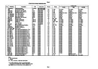
Table 21 Weldability Classification—Typical Steel Products Class I
AISI/SAE 1005, 1006, 1008, 1010, 1012, 1015, 1016, 1017, 1020, and 1021
Class II
ASTM A 36; A 3, Gr. B; A 106; A 131; A 139; A 500; A 501; A 516; A 524; A 529; A 570, Gr. 30, 33, 36, 40, 45, 50, and 55
Class III
ASTM A 242; A 441; A 537, Class 1 and 3; A 572, Gr. 42 and 50; A 588; A 618; A 656, Gr. 50; A 715, Gr. 50; API 5LX, Gr. 42; ABS, Gr. AH, DH, and EH
Class IV
ASTM A 572, Gr. 60 and 65, A656, Gr. 60, 70, and 80; A 715, Gr. 60, 70, and 80
Class V
ASTM A 514 and A 517 --`,,,```-`-`,,`,,`,`,,`---
Note: 1. See Section 6.5.2
6.4.2.1 The test piece shall be sectioned to determine whether the procedure provides the specified minimum penetration, fusion and weld profile (see 8.5). Reduced section tension tests and bend tests of the joint shall be used where specified mechanical properties of groove welds are required as indicated in Table 1.
Welded Joints for Machinery and Equipment, AWS B2.1, Specification for Welding Procedure and Performance Qualification, or AWS D1.1, Structural Welding Code— Steel, for methods of qualification testing.
6.4.2.2 Complete joint penetration groove welds in pipe or tube shall be qualified in accordance with this document. Refer to AWS D14.4, Specification for
6.4.3.1 Complete Joint Penetration Groove Welds. The method of preparing the specimens of groove welds and the number of tests required shall be in
6.4.3 Test Specimens—Preparation
11 Copyright American Welding Society Provided by IHS under license with AWS No reproduction or networking permitted without license from IHS
Not for Resale
AWS D14.3/D14.3M:2000
Table 3 Weldability Classification Structural Carbon Steels
High Strength Low Alloy Steels
Quenched and Tempered Steels
Class I
Class II
Class III1
Class IV1
Class V
30–46 205–315
35–55 240–380
40–55 275–380
50–80 345–550
90–100 620–690
Maximum CE3
0.38
0.48
0.63
—
0.74
Maximum Chemical Limits6 Carbon Manganese Phosphorus Sulfur Silicon Nickel Chromium Molybdenum* Vanadium4, 5 Titanium Zirconium Niobium (Columbium)4 Copper Boron
0.23 0.90 0.04 0.05 0.60 — — — — — — — — —
0.30 1.35 0.04 0.05 0.60 — — — — — — — — —
0.24 1.65 0.04 0.05 0.90 1.25 1.00 0.25 4, 50.104, 5 0.07 0.15 00.044 1.00 —
— — — — — — — — — — — — — —
0.22 1.50 0.04 0.05 0.90 1.50 2.00 0.65 00.085 0.10 0.15 — 0.50 0.006
Yield Strength, ksi2 Yield Strength, MPa2
Notes: 1. Only ASTM A 572, A 656, and A 715 (alloyed with some combination of niobium, vanadium, and nitrogen) are prequalified under Class IV. No nitrogen containing steel other than A 572, A 656, and A 715 are prequalified under Class III. 2. Minimum yield strengths are generally values published by the producer, or in the case where values are not published, then the value that is used for design purposes. 3. Carbon Equivalent, CE. The maximum CE values shown are based on the maximum composition limits of the materials, plus the check analysis tolerance; therefore, caution must be used when these maximum limits are approached. Reference: K. Winterton, “Weldability Prediction from Steel Composition to Avoid Heat-Affected Zone Cracking,” Welding Journal, Vol. 40, No. 6, Research Supplement, formula #3 for structural steels and formula #15 for alloy steels, pp. 253–258, June 1961 CE formula. Mn Si Carbon Steels: CE = C + -------- + ----4 4 Mn Ni Mn Cr Mo* V High Strength Low Alloy Steels: CE = C + -------- + ------ + -------- + ------ – ----------- + -----6 20 6 10 40 10 *When molybdenum exceeds 0.50 percent, then Mo is added in the calculation of CE. 4. Maximum for niobium and vanadium = 0.10 percent. 5. When welds are to be thermally stress-relieved, the deposited weld metal shall not exceed 0.05 percent vanadium. 6. Residual levels of alloys can have an influence on weldability; therefore, their effects must be considered during calculation of CE. Where levels of Mo, Cr. Ni, and V total greater than 0.20 percent, use the CE formula for high strength low alloy steel.
demonstrate that the designed weld size is obtained in accordance with requirements of 8.5.1. The depth of the groove need not exceed 1 in. [25 mm].
accordance with the figures referred to in Table 1. The test specimens shall be removed in the order given in Figures 10, 11, and 12, as appropriate. Test specimens shall be prepared in accordance with Figures 13, 14, 27, and 28. In addition to these tests, the test plate for electroslag and electrogas welding shall be nondestructively tested (see 8.5.2).
6.4.4.1 Reduced Section Tension Specimens (See Figures 13 or 14). The least width and corresponding thickness or diameter of the reduced section shall be measured before testing. The specimen shall be ruptured under tensile load, and the maximum load shall be deter-
6.4.3.2 Partial Joint Penetration Groove Welds. A welded sample of the groove design to be used in construction shall be cross-sectioned and macroetched to 12 Copyright American Welding Society Provided by IHS under license with AWS No reproduction or networking permitted without license from IHS
Not for Resale
--`,,,```-`-`,,`,,`,`,,`---
6.4.4 Method of Testing Specimens
AWS D14.3/D14.3M:2000
Figure 10—Order of Removal of Test Specimens from Welded Test Plate Over 3/4 in. [20 mm] Thick— Procedure Qualification
Figure 11—Order of Removal of Test Specimens from Welded Test Plate 3/8 in. [10 mm] Thick— Procedure Qualification
mined. The cross-sectional area shall be determined. The tensile strength shall be obtained by dividing the maximum load by the initial cross-sectional area of the gauge section. 6.4.4.2 Macroetch Test. Specimens shall be etched with a suitable solution to give a clear definition of the weld.
6.4.4.4 All-Weld-Metal Tension Test for Electroslag and Electrogas (see Figure 14). The test specimen shall be tested in accordance with AWS B4.0, Standard Methods for Mechanical Testing of Welds.
6.4.4.3 Root, Face, and Side Bend Specimens. Each specimen shall be bent to the contour shown in Annex C. Any convenient means may be used for moving the plunger member with relation to the die member. The specimen shall be placed on the die with the weld at midspan. Face-bend specimens shall be placed with the face of the weld directed toward the gap. Root bend specimens shall be placed with the root of the weld directed toward the gap. Side bend specimens shall be placed with the side showing the most significant discontinuities, if any, directed toward the gap. The specimen shall be bent through an angle of 180 degrees.
6.4.5 Test Results Required. The requirements for the test results shall be as follows: (1) Visual examination shall meet the visual quality requirements of 8.5.1. (2) Nondestructive testing required for electroslag and electrogas welds shall meet the requirements of 8.5.2. (3) Reduced Section Tension Test. The tensile strength shall be not less than that required by design. (4) Root, Face, and Side Bend Tests. For acceptance, the convex surface of the bend test specimen shall be visually examined for surface discontinuities. For 13
Copyright American Welding Society Provided by IHS under license with AWS No reproduction or networking permitted without license from IHS
Not for Resale
--`,,,```-`-`,,`,,`,`,,`---
AWS D14.3/D14.3M:2000
DETAILED DIMENSIONS ARE IN INCHES in.
3/4
12
17
mm
20
300
435
Figure 12—Order of Removal of Test Specimens from Welded Test Plate Over 3/4 in. [20 mm] Thick—Electroslag and Electrogas—Welding Procedure Qualification
(6) All-Weld-Metal Tension (electroslag and electrogas) Test. The mechanical properties shall not be less than those required by design.
acceptance, the surface shall contain no discontinuities exceeding the following dimensions: (a) 1/8 in. [3 mm] measured in any direction on the surface (b) 3/8 in. [10 mm]—the sum of the greatest dimensions of all discontinuities exceeding 1/32 in. [1 mm], but less than or equal to 1/8 in. [3 mm] (c) 1/4 in. [6 mm]—the maximum corner crack, except when that corner crack resulted from visible slag inclusion or other fusion-type discontinuities, then the 1/8 in. [3 mm] maximum shall apply. Specimens with corner cracks exceeding 1/4 in. [6 mm] with no evidence of slag inclusions or other fusion type discontinuities shall be disregarded and a replacement test specimen from the original weldment shall be tested. (5) Macroetch Tests. The specimens shall be examined for defects and any which have defects prohibited by requirements of 8.5 shall be considered as having failed.
6.4.6 Fillet Welds. Two test welds shall be made for each fillet weld procedure and position to be used in construction. One test shall be made with the maximum size single-pass fillet weld and one with the minimum size multiple-pass fillet weld that will be used in construction. Three macroetch surfaces from two specimens shall be prepared as shown in Figure 15. Each surface of the macroetch specimen shall be suitably prepared before etching. The specimens shall be etched with a suitable solution to give a clear definition of the welds. 6.4.7 Test Results Required. The requirements for the test results shall be as follows: The macroetch specimens shall be examined for defects, and any welds which have defects prohibited by 14 --`,,,```-`-`,,`,,`,`,,`---
Copyright American Welding Society Provided by IHS under license with AWS No reproduction or networking permitted without license from IHS
Not for Resale
AWS D14.3/D14.3M:2000
T
W
3/4
20>
25
25
*Note: Where the maximum plate thickness used in production is less than the value shown in the table, the maximum thickness of the production pieces may be substituted for T1 and T2.
Figure 15—Fillet Weld Soundness Test for Procedure Qualification
17 --`,,,```-`-`,,`,,`,`,,`---
Copyright American Welding Society Provided by IHS under license with AWS No reproduction or networking permitted without license from IHS
Not for Resale
AWS D14.3/D14.3M:2000
6.5.2 Base metal, filler metal, preheat, and interpass temperature shall meet the following requirements: (1) Steels listed and defined in Table 2 are prequalified for welding, provided the preheat and interpass temperatures used are no lower than those listed in Table 4 and the steels meet the mechanical property requirements of this specification. (2) Prequalified steels are divided into five weldability classes for the purpose of specifying the minimum preheat and interpass welding temperatures. Table 2 lists typical steel specifications which are in each of the classes. (3) The weldability classification for steels not listed in Table 2 may be determined by comparison to the limitations within these classes as listed in Table 3. These limitations are: (a) Minimum yield strength (b) Maximum carbon equivalent (c) Maximum limit for individual alloying element (4) Table 5 lists prequalified filler metals for complete joint penetration groove welds when the design requires that the filler metal shall equal the tensile strength of the base steel. For welds which, by design, do not require filler metals with a tensile strength equal to the base metal, lower strength filler metal may be specified. Selection of filler material and parameters used should conform to the filler metal manufacturer’s recommendations.
(1) 5/16 in. [8 mm] for all welds made in the flat position, except root passes (2) 1/4 in. [6 mm] for horizontal fillet welds (3) 1/4 in. [6 mm] for root passes of fillet welds made in the flat position and of groove welds made in the flat position with backing, and with root opening of 1/4 in. [6 mm] or more (4) 5/32 in. [4 mm] for welds made with EXX14 and low-hydrogen electrodes in the vertical and overhead positions (5) 3/16 in. [5 mm] for root passes of groove welds and for all other welds not included under 6.5.5.3 (1), 6.5.5.3 (2), 6.5.5.3 (3), and 6.5.5.3 (4) 6.5.5.4 The minimum size of a root pass shall be sufficient to prevent cracking.
Legend for Figures 16 through 22 Symbols for joint types B— butt joint C— corner joint T— T-joint BC— butt or corner TC— T- or corner joint BTC— butt, T-, or corner joint
6.5.3 The WPS for the prequalified joint procedure shall meet the applicable requirements given in 6.5.5, 6.5.6, 6.5.7, and 6.5.8. When prequalified procedures are to be used on certain components with required performance criteria tests as described in 6.3.1.1, the test assembly shall be welded using the intended WPS. Any changes to a prequalified welding procedure specification outside the applicable limits of 6.5 shall require qualification by Methods I or II.
Symbols for base metal thickness and penetration L— limited thickness—complete joint penetration U— unlimited thickness—complete joint penetration P— partial joint penetration Symbols for weld types 1— square-groove 2— single-V-groove 3— double-V-groove 4— single-bevel-groove 5— double-bevel-groove 6— single-U-groove 7— double-U-groove 8— single-J-groove 9— double-J-groove
6.5.4 Workmanship and Weld Quality Requirements. Applicable requirements of Section 8, Workmanship and Welding Quality Requirements, shall be met. 6.5.5 Prequalified Procedures for Manual Shielded Metal Arc Welding (SMAW)
6.5.5.2 The classification and size of electrode, arc voltage, and amperage shall be suited to the thickness of the material, type of material, type of groove, welding positions, and other circumstances pertaining to the work.
Small or lower case letters, e.g., a, b, c, etc., are used as symbols to differentiate between variations from a basic joint geometry with root opening closing to zero for joints that are designated by the same weld symbol. Alphabetical progression is confined within each joint penetration category, complete (L&U) and partial (P), for each welding process.
6.5.5.3 The maximum size of electrodes shall be as follows: 18 Copyright American Welding Society Provided by IHS under license with AWS No reproduction or networking permitted without license from IHS
Not for Resale
--`,,,```-`-`,,`,,`,`,,`---
Symbols for welding processes if not shielded metal arc S— submerged arc welding G— gas metal arc welding F— flux cored arc welding
6.5.5.1 The work shall be positioned for flat position welding whenever practicable.
AWS D14.3/D14.3M:2000
Square-groove weld (1) Butt joint (B) Corner joint (C)
--`,,,```-`-`,,`,,`,`,,`---
B-L1a
Square-groove weld (1) Butt joint (B) Corner joint (C)
BC-L1b
Square-groove weld (1) T-joint (T) Corner joint (C)
TC-L1a Notes: 1. Gouge the roots of joints without backing before welding other side. 2. See Table 11 for workmanship tolerances. 3. If fillet welds are used to reinforce groove welds in T-joints and corner joints, they shall be equal to T/4 but need not exceed 3/8 in. DETAILED DIMENSIONS ARE IN INCHES in.
1/32
3/32
1/8
3/16
1/4
3/8
1/2
5/8
mm
1
2.4
3
5
6
10
13
16
Figure 16—Complete Joint Penetration Prequalified Shielded Metal Arc Welded Joints
19 Copyright American Welding Society Provided by IHS under license with AWS No reproduction or networking permitted without license from IHS
Not for Resale
AWS D14.3/D14.3M:2000
Square-groove weld (1) T-joint (T) Corner joint (C)
C-L1b
Single-V-groove weld (2) Butt joint (B)
B-U2
Single-V-groove weld (2) Corner joint (C)
C-U2 Notes: 1. Gouge the roots of joints without backing before welding other side. 2. See Table 11 for workmanship tolerances. 3. If fillet welds are used to reinforce groove welds in T-joints and corner joints, they shall be equal to T/4 but need not exceed 3/8 in. DETAILED DIMENSIONS ARE IN INCHES in.
1/32
3/32
1/8
3/16
1/4
3/8
1/2
5/8
mm
1
2.4
3
5
6
10
13
16
--`,,,```-`-`,,`,,`,`,,`---
Figure 16 (Continued)—Complete Joint Penetration Prequalified Shielded Metal Arc Welded Joints
20 Copyright American Welding Society Provided by IHS under license with AWS No reproduction or networking permitted without license from IHS
Not for Resale
AWS D14.3/D14.3M:2000
Single-V-groove weld (2) Butt joint (B) Limitations for Joints B-U2a α
R
Permitted Positions
45°
1/4
All Positions
30° 20°
3/8 1/2
Flat and Overhead B-U2a
Single-V-groove weld (2) Corner joint (C) Limitations for Joints C-U2a α
R
Permitted Positions
45°
1/4
All Positions
30° 20°
3/8 1/2
Flat and Overhead
C-U2a
Double-V-groove weld (3) Butt joint (B)
B-U3* Notes: 1. Gouge the roots of joints without backing before welding other side. 2. See Table 11 for workmanship tolerances. 3. If fillet welds are used to reinforce groove welds in T-joints and corner joints, they shall be equal to T/4 but need not exceed 3/8 in. *The use of these welds shall preferably be limited to base metal thickness of 5/8 in. or larger. DETAILED DIMENSIONS ARE IN INCHES in.
1/32
3/32
1/8
3/16
1/4
3/8
1/2
5/8
mm
1
2.4
3
5
6
10
13
16
Figure 16 (Continued)—Complete Joint Penetration Prequalified Shielded Metal Arc Welded Joints
21 --`,,,```-`-`,,`,,`,`,,`---
Copyright American Welding Society Provided by IHS under license with AWS No reproduction or networking permitted without license from IHS
Not for Resale
AWS D14.3/D14.3M:2000
Double-V-groove weld (3) Butt joint (B) Limitations for Joints B-U3a α
R
Permitted Positions
45°
1/4
All Positions
30° 20°
3/8 1/2
Flat and Overhead
B-U3a*
Single-bevel-groove weld (4) T-joint (T) Corner joint (C)
TC-U4
Single-bevel-groove weld (4) T-joint (T)—Skew Corner joint (C)—Skew
TC-U4a Notes: 1. Gouge the roots of joints without backing before welding other side. 2. See Table 11 for workmanship tolerances. *The use of these welds shall preferably be limited to base metal thickness of 5/8 in. or larger. DETAILED DIMENSIONS ARE IN INCHES in.
1/32
3/32
1/8
3/16
1/4
3/8
1/2
5/8
mm
1
2.4
3
5
6
10
13
16
Figure 16 (Continued)—Complete Joint Penetration Prequalified Shielded Metal Arc Welded Joints 22 Copyright American Welding Society Provided by IHS under license with AWS No reproduction or networking permitted without license from IHS
Not for Resale
--`,,,```-`-`,,`,,`,`,,`---
3. If fillet welds are used to reinforce groove welds in T-joints and corner joints, they shall be equal to T/4 but need not exceed 3/8 in.
AWS D14.3/D14.3M:2000
Single-bevel-groove weld (4) T-joint (T) Corner joint (C) --`,,,```-`-`,,`,,`,`,,`---
Limitations for Joints TC-U4b α
R
Permitted Positions
45°
1/4
All Positions
30°
3/8
Flat and Overhead
TC-U4b
Single-bevel-groove weld (4) T-joint (T) Corner joint (C) Limitations for Joints TC-U4c α
R
Permitted Positions
45°
1/4
All Positions
30°
3/8
Flat and Overhead
TC-U4c
Single-bevel-groove weld (4) Butt joint (B)
B-U4 Notes: 1. Gouge the roots of joints without backing before welding other side. 2. See Table 11 for workmanship tolerances. 3. If fillet welds are used to reinforce groove welds in T-joints and corner joints, they shall be equal to T/4 but need not exceed 3/8 in. DETAILED DIMENSIONS ARE IN INCHES in.
1/32
3/32
1/8
3/16
1/4
3/8
1/2
5/8
mm
1
2.4
3
5
6
10
13
16
Figure 16 (Continued)—Complete Joint Penetration Prequalified Shielded Metal Arc Welded Joints
23 Copyright American Welding Society Provided by IHS under license with AWS No reproduction or networking permitted without license from IHS
Not for Resale
AWS D14.3/D14.3M:2000
Single-bevel-groove weld (4) Butt joint (B)
B-U4a
Double-bevel-groove weld (5) Butt joint (B)
B-U5*
Double-bevel-groove weld (5) T-joint (T) Corner joint (C)
TC-U5 Notes: 1. Gouge the roots of joints without backing before welding other side. 2. See Table 11 for workmanship tolerances. 3. If fillet welds are used to reinforce groove welds in T-joints and corner joints, they shall be equal to T/4 but need not exceed 3/8 in. *The use of these welds shall preferably be limited to base metal thickness of 5/8 in. or larger. DETAILED DIMENSIONS ARE IN INCHES in.
1/32
3/32
1/8
3/16
1/4
3/8
1/2
5/8
mm
1
2.4
3
5
6
10
13
16
Figure 16 (Continued)—Complete Joint Penetration Prequalified Shielded Metal Arc Welded Joints
--`,,,```-`-`,,`,,`,`,,`---
Copyright American Welding Society Provided by IHS under license with AWS No reproduction or networking permitted without license from IHS
24 Not for Resale
AWS D14.3/D14.3M:2000
Double-bevel-groove weld (5) Butt joint (B) T-joint (T) Corner joint (C) --`,,,```-`-`,,`,,`,`,,`---
B-U5a*
Double-bevel-groove weld (5) T-joint (T) Corner joint (C) Limitations for Joints TC-U5b α
R
Permitted Positions
45°
1/4
All Positions
30°
3/8
Flat and Overhead
TC-U5b*
Double-bevel-groove weld (5) T-joint (T) Corner joint (C) Limitations for Joints TC-U5c α
R
45°
1/4
All Positions
30°
3/8
Flat and Overhead
Permitted Positions
TC-U5c* Notes: 1. Gouge the roots of joints without backing before welding other side. 2. See Table 11 for workmanship tolerances. 3. If fillet welds are used to reinforce groove welds in T-joints and corner joints, they shall be equal to T/4 but need not exceed 3/8 in. *The use of these welds shall preferably be limited to base metal thickness of 5/8 in. or larger. DETAILED DIMENSIONS ARE IN INCHES in.
1/32
3/32
1/8
3/16
1/4
3/8
1/2
5/8
mm
1
2.4
3
5
6
10
13
16
Figure 16 (Continued)—Complete Joint Penetration Prequalified Shielded Metal Arc Welded Joints 25 Copyright American Welding Society Provided by IHS under license with AWS No reproduction or networking permitted without license from IHS
Not for Resale
AWS D14.3/D14.3M:2000
Double-bevel-groove weld (5) T-joint (T) Corner joint (C)
TC-U5d*
Single-U-groove weld (6) Butt joint (B) Corner joint (C) Limitations for Joints B-U6 α
Permitted Positions
45°
All Positions
20°
Flat and Overhead B-U6
Single-U-groove weld (6) Butt joint (B) Corner joint (C) Limitations for Joints BC-U6 α
Permitted Positions
45°
All Positions
30° 20°
Flat and Overhead
BC-U6 Notes: 1. Gouge the roots of joints without backing before welding other side. 2. See Table 11 for workmanship tolerances. 3. If fillet welds are used to reinforce groove welds in T-joints and corner joints, they shall be equal to T/4 but need not exceed 3/8 in. *The use of these welds shall preferably be limited to base metal thickness of 5/8 in. or larger. DETAILED DIMENSIONS ARE IN INCHES in.
1/32
3/32
1/8
3/16
1/4
3/8
1/2
5/8
mm
1
2.4
3
5
6
10
13
16
Figure 16 (Continued)—Complete Joint Penetration Prequalified Shielded Metal Arc Welded Joints
26 Copyright American Welding Society Provided by IHS under license with AWS No reproduction or networking permitted without license from IHS
Not for Resale
--`,,,```-`-`,,`,,`,`,,`---
AWS D14.3/D14.3M:2000
Double-bevel-groove weld (7) Butt joint (B) Limitations for Joints B-U7 α
Permitted Positions
45°
All Positions
20°
Flat and Overhead
B-U7*
--`,,,```-`-`,,`,,`,`,,`---
Single-U-groove weld (8) Butt joint (B)
B-U8
Single-J-groove weld (8) T-joint (T) Corner joint (C) Limitations for Joints TC-U8a α
Permitted Positions
45°
All Positions
30°
Flat and Overhead
TC-U8a Notes: 1. Gouge the roots of joints without backing before welding other side. 2. See Table 11 for workmanship tolerances. 3. If fillet welds are used to reinforce groove welds in T-joints and corner joints, they shall be equal to T/4 but need not exceed 3/8 in. *The use of these welds shall preferably be limited to base metal thickness of 5/8 in. or larger. DETAILED DIMENSIONS ARE IN INCHES in.
1/32
3/32
1/8
3/16
1/4
3/8
1/2
5/8
mm
1
2.4
3
5
6
10
13
16
Figure 16 (Continued)—Complete Joint Penetration Prequalified Shielded Metal Arc Welded Joints 27 Copyright American Welding Society Provided by IHS under license with AWS No reproduction or networking permitted without license from IHS
Not for Resale
AWS D14.3/D14.3M:2000
Single-J-groove weld (8) T-joint (T) Corner joint (C)
α
Permitted Positions
45°
All Positions
30°
Flat and Overhead --`,,,```-`-`,,`,,`,`,,`---
Limitations for Joints TC-U8b
TC-U8b
Double-J-groove weld (9) Butt joint (B)
B-U9*
Double-J-groove weld (9) T-joint (T) Corner joint (C) Limitations for Joints TC-U9a α
Permitted Positions
45°
All Positions
30°
Flat and Overhead
TC-U9a* Notes: 1. Gouge the roots of joints without backing before welding other side. 2. See Table 11 for workmanship tolerances. 3. If fillet welds are used to reinforce groove welds in T-joints and corner joints, they shall be equal to T/4 but need not exceed 3/8 in. *The use of these welds shall preferably be limited to base metal thickness of 5/8 in. or larger. DETAILED DIMENSIONS ARE IN INCHES in.
1/32
3/32
1/8
3/16
1/4
3/8
1/2
5/8
mm
1
2.4
3
5
6
10
13
16
Figure 16 (Continued)—Complete Joint Penetration Prequalified Shielded Metal Arc Welded Joints
28 Copyright American Welding Society Provided by IHS under license with AWS No reproduction or networking permitted without license from IHS
Not for Resale
AWS D14.3/D14.3M:2000
--`,,,```-`-`,,`,,`,`,,`---
Double-J-groove weld (9) T-joint (T) Corner joint (C) Limitations for Joints TC-U9b α
Permitted Positions
45°
All Positions
30° 20°
Flat and Overhead
TC-U9b* Notes: 1. Gouge the roots of joints without backing before welding other side. 2. See Table 11 for workmanship tolerances. 3. If fillet welds are used to reinforce groove welds in T-joints and corner joints, they shall be equal to T/4 but need not exceed 3/8 in. *The use of these welds shall preferably be limited to base metal thickness of 5/8 in. or larger.
Figure 16 (Continued)—Complete Joint Penetration Prequalified Shielded Metal Arc Welded Joints
Square-groove weld (1) Butt joint (B)
WELD SIZE (E) = T – 1/32
B-P1*
Notes: 1. See Table 11 for workmanship tolerances. 2. Minimum root face shall be 1/8 in. when specified. *Joints welded from one side. DETAILED DIMENSIONS ARE IN INCHES in.
1/32
1/16
3/32
1/8
3/16
1/4
3/8
1/2
5/8
mm
1
1.6
2.4
3
5
6
10
13
16
Figure 17—Partial Joint Penetration Prequalified Shielded Metal Arc Welded Joints
29 Copyright American Welding Society Provided by IHS under license with AWS No reproduction or networking permitted without license from IHS
Not for Resale
AWS D14.3/D14.3M:2000
Square-groove weld (1) Butt joint (B)
T WELD SIZE (E) = --2
B-P1a*
Square-groove weld (1) Butt joint (B)
ROOT NEED NOT BE CHIPPED BEFORE WELDING SECOND SIDE
3T TOTAL WELD SIZE (E) = ------4
B-P1b
Single-V-groove weld (2) Butt joint (B) Corner joint (C)
BC-P2 Note 2
WELD SIZE (E) = S Notes: 1. See Table 11 for workmanship tolerances. 2. Minimum root face shall be 1/8 in. when specified. *Joints welded from one side.
DETAILED DIMENSIONS ARE IN INCHES in.
1/32
1/16
3/32
1/8
3/16
1/4
3/8
1/2
5/8
mm
1
1.6
2.4
3
5
6
10
13
16
Figure 17 (Continued)—Partial Joint Penetration Prequalified Shielded Metal Arc Welded Joints
--`,,,```-`-`,,`,,`,`,,`---
Copyright American Welding Society Provided by IHS under license with AWS No reproduction or networking permitted without license from IHS
30 Not for Resale
AWS D14.3/D14.3M:2000
--`,,,```-`-`,,`,,`,`,,`---
Single-V-groove weld (2) Butt joint (B) Corner joint (C)
WELD SIZE (E) = T – 1/32
BC-P2a**
Double-V-groove weld (3) Butt joint (B)
EFFECTIVE THROAT (E) = S B-P3 Note 2
*WELD SIZE (E) = S
Single-bevel-groove weld (4) Butt joint (B) T-joint (T) Corner joint (C)
WELD SIZE (E) = S – 1/8
BTC-P4
Notes: 1. See Table 11 for workmanship tolerances. 2. Minimum root face shall be 1/8 in. when specified. *Total weld size (E) = (E) Side 1 plus (E) of Side 2. **Joint welded from one side. DETAILED DIMENSIONS ARE IN INCHES in.
1/32
3/32
1/8
3/16
1/4
3/8
1/2
5/8
mm
1
2.4
3
5
6
10
13
16
Figure 17 (Continued)—Partial Joint Penetration Prequalified Shielded Metal Arc Welded Joints
31 Copyright American Welding Society Provided by IHS under license with AWS No reproduction or networking permitted without license from IHS
Not for Resale
AWS D14.3/D14.3M:2000
Single-bevel-groove weld (4) Butt joint (B)
EFFECTIVE THROAT (E) = T – 1/32
B-P4a**
Single-bevel-groove weld (5) Butt joint (B) T-joint (T) Corner joint (C)
*WELD SIZE (E) = S – 1/8
BTC-P5
Single-U-groove weld (6) Butt joint (B) Corner joint (C)
WELD SIZE (E) = S
BC-P6
Notes: 1. See Table 11 for workmanship tolerances. 2. Minimum root face shall be 1/8 in. when specified. *Total weld size (E) = (E) Side 1 plus (E) of Side 2. **Joint welded from one side.
in.
1/32
3/32
1/8
3/16
1/4
3/8
1/2
5/8
mm
1
2.4
3
5
6
10
13
16
Figure 17 (Continued)—Partial Joint Penetration Prequalified Shielded Metal Arc Welded Joints
32 Copyright American Welding Society Provided by IHS under license with AWS No reproduction or networking permitted without license from IHS
Not for Resale
--`,,,```-`-`,,`,,`,`,,`---
DETAILED DIMENSIONS ARE IN INCHES
AWS D14.3/D14.3M:2000
Double-U-groove weld (7) Butt joint (B)
B-P7 Note 2
*WELD SIZE (E) = S
--`,,,```-`-`,,`,,`,`,,`---
Single-J-groove weld (8) Butt joint (B) T-joint (T) Corner joint (C)
WELD SIZE (E) = S
BTC-P8
Double-J-groove weld (9) Butt joint (B) T-joint (T) Corner joint (C)
*WELD SIZE (E) = S
BTC-P9
Notes: 1. See Table 11 for workmanship tolerances. 2. Minimum root face shall be 1/8 in. when specified. *Total weld size (E) = (E) Side 1 plus (E) of Side 2. DETAILED DIMENSIONS ARE IN INCHES in.
1/32
3/32
1/8
3/16
1/4
3/8
1/2
5/8
mm
1
2.4
3
5
6
10
13
16
Figure 17 (Continued)—Partial Joint Penetration Prequalified Shielded Metal Arc Welded Joints
33 Copyright American Welding Society Provided by IHS under license with AWS No reproduction or networking permitted without license from IHS
Not for Resale
AWS D14.3/D14.3M:2000
Square-groove weld (1) Butt joint (B)
B-L1-S
Square-groove weld (1) T-joint (T) Corner joint (C)
TC-L1-S
Single-V-groove weld (2) Butt joint (B)
B-L2-S Notes: 1. If fillet welds are used to reinforce groove welds in T-joints and corner joints, they shall be equal to T/4 but need not exceed 3/8 in. 2. See Table 11 for workmanship tolerances. 3. Total weld size (E) = (E) Side 1 plus (E) of Side 2. 4. Gouge the roots of joints without backing before welding other side. DETAILED DIMENSIONS ARE IN INCHES in.
1/32
3/32
1/8
3/16
1/4
3/8
1/2
5/8
3/4
1
1-1/2
2
mm
1
2.4
3
5
6
10
13
16
20
25
38
50
Figure 18—Complete Joint Penetration Prequalified Submerged Arc Welded Joints
34 --`,,,```-`-`,,`,,`,`,,`---
Copyright American Welding Society Provided by IHS under license with AWS No reproduction or networking permitted without license from IHS
Not for Resale
AWS D14.3/D14.3M:2000
Single-V-groove weld (2) Butt joint (B) T
T1
Over 1/4 to 1 Over 1 to 1-1/2 Over 1-1/2 to 2
1/4 1/2 5/8
B-L2a-S
Square-V-groove weld (2) Butt joint (B) Corner joint (C)
BC-L2b-S
Single-V-groove weld (2) Butt joint (B) Limitations for Joints Maximum Thickness (T)
α
R
B-L2c-S
30°
1/4
1/2
B-U2a-S
20°
5/8
Unlimited B-L2c-S and B-U2a-S
--`,,,```-`-`,,`,,`,`,,`---
Notes: 1. If fillet welds are used to reinforce groove welds in T-joints and corner joints, they shall be equal to T/4 but need not exceed 3/8 in. 2. See Table 11 for workmanship tolerances. 3. Total weld size (E) = (E) Side 1 plus (E) of Side 2. 4. Gouge root of joints without backing before welding other side. DETAILED DIMENSIONS ARE IN INCHES in.
1/32
3/32
1/8
3/16
1/4
3/8
1/2
5/8
3/4
1
1-1/2
2
mm
1
2.4
3
5
6
10
13
16
20
25
38
50
Figure 18 (Continued)—Complete Joint Penetration Prequalified Submerged Arc Welded Joints
35 Copyright American Welding Society Provided by IHS under license with AWS No reproduction or networking permitted without license from IHS
Not for Resale
AWS D14.3/D14.3M:2000
Single-V-groove weld (2) Corner joint (C) Limitations for Joints α
R
Maximum Thickness (T)
C-L2c-S
30°
1/4
1/2
C-U2a-S
20°
5/8
Unlimited
C-L2c-S and C-U2a-S
Double-V-groove weld (3) Butt joint (B)
B-L3-S
Double-V-groove weld (3) Butt joint (B) INCHES
MILLIMETERS
T
T1
T
T1
Over 2 to 2-1/2 Over 2-1/2 to 3 Over 3 to 3-5/8 Over 3-5/8 to 4 Over 4 to 4-3/4 Over 4-3/4 to 5-1/2 Over 5-1/2 to 6-1/4
1-3/8 1-3/4 2-1/8 2-3/8 2-3/4 3-1/4 3-3/4
Over 50 to 65 Over 65 to 75 Over 75 to 92 Over 92 to 100 Over 100 to 120 Over 120 to 140 Over 140 to 160
35 45 55 60 70 83 95
--`,,,```-`-`,,`,,`,`,,`---
For T > 6-1/4 or T < 2 T1 = 2/3 (T – 1/4)
For T > 160 or T < 50 T1 = 2/3 (T – 6)
B-U3-S
Notes: 1. If fillet welds are used to reinforce groove welds in T-joints and corner joints, they shall be equal to T/4 but need not exceed 3/8 in. 2. See Table 11 for workmanship tolerances. 3. Total weld size (E) = (E) Side 1 plus (E) of Side 2. 4. Gouge root of joints without backing before welding other side. DETAILED DIMENSIONS ARE IN INCHES in.
1/32
3/32
1/8
3/16
1/4
3/8
1/2
5/8
3/4
1
1-1/2
2
mm
1
2.4
3
5
6
10
13
16
20
25
38
50
Figure 18 (Continued)—Complete Joint Penetration Prequalified Submerged Arc Welded Joints
36 Copyright American Welding Society Provided by IHS under license with AWS No reproduction or networking permitted without license from IHS
Not for Resale
AWS D14.3/D14.3M:2000
Double-V-groove weld (3) Butt joint (B)
B-U3a-S
Double-V-groove weld (3) Butt joint (B)
B-U3b-S
Single-bevel-groove weld (4) Butt joint (B) T-joint (T) Corner joint (C)
BTC-L4-S Notes: 1. If fillet welds are used to reinforce groove welds in T-joints and corner joints, they shall be equal to T/4 but need not exceed 3/8 in. 2. See Table 11 for workmanship tolerances. 3. Total weld size (E) = (E) Side 1 plus (E) of Side 2. 4. Gouge root of joints without backing before welding other side. DETAILED DIMENSIONS ARE IN INCHES in.
1/32
3/32
1/8
3/16
1/4
3/8
1/2
5/8
3/4
1
1-1/2
2
mm
1
2.4
3
5
6
10
13
16
20
25
38
50
Figure 18 (Continued)—Complete Joint Penetration Prequalified Submerged Arc Welded Joints
37 Copyright American Welding Society Provided by IHS under license with AWS No reproduction or networking permitted without license from IHS
--`,,,```-`-`,,`,,`,`,,`---
Not for Resale
AWS D14.3/D14.3M:2000
Single-bevel-groove weld (4) Butt joint (B) T-joint (T) Corner joint (C) α
R
45° 30°
1/4 3/8
BTC-U4a-S
Single-bevel-groove weld (4) T-joint (T) Corner joint (C)
TC-L4b-S
Single-bevel-groove weld (4) T-joint (T) Corner joint (C) α
R
45° 30°
1/4 3/8
TC-U4c-S Notes: 1. If fillet welds are used to reinforce groove welds in T-joints and corner joints, they shall be equal to T/4 but need not exceed 3/8 in. 2. See Table 11 for workmanship tolerances. 3. Total weld size (E) = (E) Side 1 plus (E) of Side 2. 4. Gouge root of joints without backing before welding other side. DETAILED DIMENSIONS ARE IN INCHES in.
1/32
3/32
1/8
3/16
1/4
3/8
1/2
5/8
3/4
1
1-1/2
2
mm
1
2.4
3
5
6
10
13
16
20
25
38
50
Figure 18 (Continued)—Complete Joint Penetration Prequalified Submerged Arc Welded Joints
38 --`,,,```-`-`,,`,,`,`,,`---
Copyright American Welding Society Provided by IHS under license with AWS No reproduction or networking permitted without license from IHS
Not for Resale
AWS D14.3/D14.3M:2000
Double-bevel-groove weld (5) Butt joint (B) T-joint (T) Corner joint (C)
BTC-U5-S
Double-U-groove weld (7) Butt joint (B)
--`,,,```-`-`,,`,,`,`,,`---
B-U7-S Notes: 1. If fillet welds are used to reinforce groove welds in T-joints and corner joints, they shall be equal to T/4 but need not exceed 3/8 in. 2. See Table 11 for workmanship tolerances. 3. Total weld size (E) = (E) Side 1 plus (E) of Side 2. 4. Gouge root of joints without backing before welding other side. DETAILED DIMENSIONS ARE IN INCHES in.
1/32
3/32
1/8
3/16
1/4
3/8
1/2
5/8
3/4
1
1-1/2
2
mm
1
2.4
3
5
6
10
13
16
20
25
38
50
Figure 18 (Continued)—Complete Joint Penetration Prequalified Submerged Arc Welded Joints
39 Copyright American Welding Society Provided by IHS under license with AWS No reproduction or networking permitted without license from IHS
Not for Resale
AWS D14.3/D14.3M:2000
Single-V-groove weld (2) Butt joint (B) Corner joint (C)
WELD SIZE (E) = S
BC-P2-S
Double-V-groove weld (3) Butt joint (B)
--`,,,```-`-`,,`,,`,`,,`---
*WELD SIZE (E) = S
B-P3-S
Single-bevel-groove weld (4) Butt joint (B) T-joint (T) Corner joint (C)
WELD SIZE (E) = S – 1/8
BTC-P4
Notes: 1. See Table 11 for workmanship tolerances. 2. Minimum root face shall be 1/8 in. *Total weld size (E) = (E) Side 1 plus (E) of Side 2. DETAILED DIMENSIONS ARE IN INCHES in.
1/32
3/32
1/8
3/16
1/4
3/8
1/2
5/8
mm
1
2.4
3
5
6
10
13
16
Figure 19—Partial Joint Penetration Prequalified Submerged Arc Welded Joints
40 Copyright American Welding Society Provided by IHS under license with AWS No reproduction or networking permitted without license from IHS
Not for Resale
AWS D14.3/D14.3M:2000
Single-bevel-groove weld (5) Butt joint (B) T-joint (T) Corner joint (C)
*WELD SIZE (E) = S – 1/8
BTC-P5 Note 1
Single-U-groove weld (6) Butt joint (B) Corner joint (C)
WELD SIZE (E) = S
BC-P6-SNote 2
WELD SIZE (E) = S – 1/8
--`,,,```-`-`,,`,,`,`,,`---
Single-U-groove weld (6) Butt joint (B) Corner joint (C)
BC-P6Note 2
General Note: See Table 11 for workmanship tolerances. Notes: 1. Minimum root face shall be 1/8 in. 2. Minimum root of face of joint shall be 1/4 in. *Total weld size (E) = (E) Side 1 plus (E) of Side 2. DETAILED DIMENSIONS ARE IN INCHES in.
1/32
3/32
1/8
3/16
1/4
3/8
1/2
5/8
mm
1
2.4
3
5
6
10
13
16
Figure 19 (Continued)—Partial Joint Penetration Prequalified Submerged Arc Welded Joints
41 Copyright American Welding Society Provided by IHS under license with AWS No reproduction or networking permitted without license from IHS
Not for Resale
AWS D14.3/D14.3M:2000
Double-U-groove weld (7) Butt joint (B)
*WELD SIZE (E) = S
B-P7-S
--`,,,```-`-`,,`,,`,`,,`---
Single-J-groove weld (8) Butt joint (B) T-joint (T) Corner joint (C)
WELD SIZE (E) = S
BTC-P8-S
Double-J-groove weld (9) Butt joint (B) T-joint (T) Corner joint (C)
*WELD SIZE (E) = S
BTC-P9-S
Notes: 1. See Table 11 for workmanship tolerances. 2. Minimum root of face of joint shall be 1/4 in. *Total weld size (E) = (E) Side 1 plus (E) of Side 2. DETAILED DIMENSIONS ARE IN INCHES in.
1/32
3/32
1/8
3/16
1/4
3/8
1/2
5/8
mm
1
2.4
3
5
6
10
13
16
Figure 19 (Continued)—Partial Joint Penetration Prequalified Submerged Arc Welded Joints
42 Copyright American Welding Society Provided by IHS under license with AWS No reproduction or networking permitted without license from IHS
Not for Resale
AWS D14.3/D14.3M:2000
Square-groove weld (1) Butt joint (B)
B-L1-GF
Square-groove weld (1) T-joint (T) Corner joint (C)
TC-L1-GF
Square-groove weld (1) Butt joint (B) Corner joint (C)
BC-L1a-GF Notes: 1. Gouge the roots of joints without backing before welding other side. 2. See Table 11 for workmanship tolerances. 3. If fillet welds are used to reinforce groove welds in T-joints and corner joints, they shall be equal to T/4 but need not exceed 3/8 in. 4. Not prequalified for gas metal arc welding using short circuiting transfer or pulsed arc when the average current and voltage are insufficient to promote the spray or globular modes of metal transfer. DETAILED DIMENSIONS ARE IN INCHES in.
1/32
3/32
1/8
3/16
1/4
3/8
1/2
5/8
mm
1
2.4
3
5
6
10
13
16
Figure 20—Complete Joint Penetration Prequalified Gas Metal and Flux Cored Arc Welded Joints 43 Copyright American Welding Society Provided by IHS under license with AWS No reproduction or networking permitted without license from IHS
Not for Resale
--`,,,```-`-`,,`,,`,`,,`---
AWS D14.3/D14.3M:2000
Single-V-groove weld (2) Corner joint (C)
C-U2-GF
Single-V-groove weld (2) Butt joint (B)
B-U2-GF
Single-V-groove weld (2) Corner joint (C) Limitations for Joints C-U2a-GF Shielding
Positions
R
Gas
F, V, & O
3/16
No Gas
Flat Only V & O Only
3/8 1/4 C-U2a-GF
Notes: 1. Gouge the roots of joints without backing before welding other side. 2. See Table 11 for workmanship tolerances. 3. If fillet welds are used to reinforce groove welds in T-joints and corner joints, they shall be equal to T/4 but need not exceed 3/8 in. 4. Not prequalified for gas metal arc welding using short circuiting transfer or pulsed arc when the average current and voltage are insufficient to promote the spray or globular modes of metal transfer. DETAILED DIMENSIONS ARE IN INCHES in.
1/32
3/32
1/8
3/16
1/4
3/8
1/2
5/8
mm
1
2.4
3
5
6
10
13
16
Figure 20 (Continued)—Complete Joint Penetration Prequalified Gas Metal and Flux Cored Arc Welded Joints
--`,,,```-`-`,,`,,`,`,,`---
44
Copyright American Welding Society Provided by IHS under license with AWS No reproduction or networking permitted without license from IHS
Not for Resale
AWS D14.3/D14.3M:2000
Single-V-groove weld (2) Butt joint (B) Limitations for Joints B-U2a-GF Shielding
Positions
R
Gas
F, V, & O
3/16
No Gas
Flat Only V & O Only
3/8 1/4 B-U2a-GF
--`,,,```-`-`,,`,,`,`,,`---
Double-V-groove weld (3) Butt joint (B)
B-U3-GF*
Single-bevel-groove weld (4) Butt joint (B)
B-U4-GF Notes: 1. Gouge the roots of joints without backing before welding other side. 2. See Table 11 for workmanship tolerances. 3. If fillet welds are used to reinforce groove welds in T-joints and corner joints, they shall be equal to T/4 but need not exceed 3/8 in. 4. Not prequalified for gas metal arc welding using short circuiting transfer or pulsed arc when the average current and voltage are insufficient to promote the spray or globular modes of metal transfer. *The use of these welds shall preferably be limited to base metal thickness of 5/8 in. or larger. DETAILED DIMENSIONS ARE IN INCHES in.
1/32
3/32
1/8
3/16
1/4
3/8
1/2
5/8
mm
1
2.4
3
5
6
10
13
16
Figure 20 (Continued)—Complete Joint Penetration Prequalified Gas Metal and Flux Cored Arc Welded Joints
45 Copyright American Welding Society Provided by IHS under license with AWS No reproduction or networking permitted without license from IHS
Not for Resale
AWS D14.3/D14.3M:2000
Single-bevel-groove weld (4) T-joint (T) Corner joint (C)
TC-U4-GF
Single-bevel-groove weld (4) T-joint (T) Corner joint (C)
--`,,,```-`-`,,`,,`,`,,`---
TC-U4a-GF
Single-bevel-groove weld (4) Butt joint (B) Limitations for Joints B-U4b-GF Shielding
Positions
R
Gas
All
30°
3/16
No Gas
Flat Only All
30° 45°
3/8 1/4
B-U4b-GF
Notes: 1. Gouge the roots of joints without backing before welding other side. 2. See Table 11 for workmanship tolerances. 3. If fillet welds are used to reinforce groove welds in T-joints and corner joints, they shall be equal to T/4 but need not exceed 3/8 in. 4. Not prequalified for gas metal arc welding using short circuiting transfer or pulsed arc when the average current and voltage are insufficient to promote the spray or globular modes of metal transfer. DETAILED DIMENSIONS ARE IN INCHES in.
1/32
3/32
1/8
3/16
1/4
3/8
1/2
5/8
mm
1
2.4
3
5
6
10
13
16
Figure 20 (Continued)—Complete Joint Penetration Prequalified Gas Metal and Flux Cored Arc Welded Joints
46 Copyright American Welding Society Provided by IHS under license with AWS No reproduction or networking permitted without license from IHS
Not for Resale
AWS D14.3/D14.3M:2000
Single-bevel-groove weld (4) T-joint (T) Corner joint (C) Limitations for Joints B-U4c-GF Shielding
Positions
R
Gas
All
30°
3/16
No Gas
Flat Only All
30° 45°
3/8 1/4 TC-U4c-GF
Single-bevel-groove weld (4) T-joint (T) Corner joint (C)
Shielding
Positions
--`,,,```-`-`,,`,,`,`,,`---
Limitations for Joints B-U4d-GF R
Gas
All
30°
3/16
No Gas
Flat Only All
30° 45°
3/8 1/4 TC-U4d-GF
Double-bevel-groove weld (5) T-joint (T) Corner joint (C)
TC-U5-GF* Notes: 1. Gouge the roots of joints without backing before welding other side. 2. See Table 11 for workmanship tolerances. 3. If fillet welds are used to reinforce groove welds in T-joints and corner joints, they shall be equal to T/4 but need not exceed 3/8 in. 4. Not prequalified for gas metal arc welding using short circuiting transfer or pulsed arc when the average current and voltage are insufficient to promote the spray or globular modes of metal transfer. *The use of these welds shall preferably be limited to base metal thickness of 5/8 in. or larger. DETAILED DIMENSIONS ARE IN INCHES in.
1/32
3/32
1/8
3/16
1/4
3/8
1/2
5/8
mm
1
2.4
3
5
6
10
13
16
Figure 20 (Continued)—Complete Joint Penetration Prequalified Gas Metal and Flux Cored Arc Welded Joints 47 Copyright American Welding Society Provided by IHS under license with AWS No reproduction or networking permitted without license from IHS
Not for Resale
AWS D14.3/D14.3M:2000
Double-bevel-groove weld (5) Butt joint (B)
B-U5-GF*
--`,,,```-`-`,,`,,`,`,,`---
Single-U-groove weld (6) Butt joint (B) Corner joint (C)
BC-U6-GF
Double-U-groove weld (7) Butt joint (B)
B-U7-GF* Notes: 1. Gouge the roots of joints without backing before welding other side. 2. See Table 11 for workmanship tolerances. 3. If fillet welds are used to reinforce groove welds in T-joints and corner joints, they shall be equal to T/4 but need not exceed 3/8 in. 4. Not prequalified for gas metal arc welding using short circuiting transfer or pulsed arc when the average current and voltage are insufficient to promote the spray or globular modes of metal transfer. *The use of these welds shall preferably be limited to base metal thickness of 5/8 in. or larger. DETAILED DIMENSIONS ARE IN INCHES in.
1/32
3/32
1/8
3/16
1/4
3/8
1/2
5/8
mm
1
2.4
3
5
6
10
13
16
Figure 20 (Continued)—Complete Joint Penetration Prequalified Gas Metal and Flux Cored Arc Welded Joints
48 Copyright American Welding Society Provided by IHS under license with AWS No reproduction or networking permitted without license from IHS
Not for Resale
AWS D14.3/D14.3M:2000
Single-J-groove weld (8) T-joint (T) Corner joint (C)
TC-U8-GF
Single-J-groove weld (8) T-joint (T) Corner joint (C)
TC-U8a-GF
Single-J-groove weld (8) Butt joint (B)
B-U8b-GF Notes: 1. Gouge the roots of joints without backing before welding other side. 2. See Table 11 for workmanship tolerances. 3. If fillet welds are used to reinforce groove welds in T-joints and corner joints, they shall be equal to T/4 but need not exceed 3/8 in. 4. Not prequalified for gas metal arc welding using short circuiting transfer or pulsed arc when the average current and voltage are insufficient to promote the spray or globular modes of metal transfer. DETAILED DIMENSIONS ARE IN INCHES in.
1/32
3/32
1/8
3/16
1/4
3/8
1/2
5/8
mm
1
2.4
3
5
6
10
13
16
Figure 20 (Continued)—Complete Joint Penetration Prequalified Gas Metal and Flux Cored Arc Welded Joints 49 --`,,,```-`-`,,`,,`,`,,`---
Copyright American Welding Society Provided by IHS under license with AWS No reproduction or networking permitted without license from IHS
Not for Resale
AWS D14.3/D14.3M:2000
--`,,,```-`-`,,`,,`,`,,`---
Double-J-groove weld (9) Butt joint (B)
B-U9-GF*
Double-J-groove weld (9) T-joint (T) Corner joint (C)
TC-U9a-GF*
Double-J-groove weld (9) T-joint (T) Corner joint (C)
TC-U9b-GF* Notes: 1. Gouge the roots of joints without backing before welding other side. 2. See Table 11 for workmanship tolerances. 3. If fillet welds are used to reinforce groove welds in T-joints and corner joints, they shall be equal to T/4 but need not exceed 3/8 in. 4. Not prequalified for gas metal arc welding using short circuiting transfer or pulsed arc when the average current and voltage are insufficient to promote the spray or globular modes of metal transfer. *The use of these welds shall preferably be limited to base metal thickness of 5/8 in. or larger. DETAILED DIMENSIONS ARE IN INCHES in.
1/32
3/32
1/8
3/16
1/4
3/8
1/2
5/8
mm
1
2.4
3
5
6
10
13
16
Figure 20 (Continued)—Complete Joint Penetration Prequalified Gas Metal and Flux Cored Arc Welded Joints 50 Copyright American Welding Society Provided by IHS under license with AWS No reproduction or networking permitted without license from IHS
Not for Resale
AWS D14.3/D14.3M:2000
Single-V-groove weld (2) Butt joint (B) Corner joint (C)
WELD SIZE (E) = S
BC-P2-GF
Double-V-groove weld (3) Butt joint (B)
*WELD SIZE (E) = S
B-P3-GF
Single-bevel-groove weld (4) Butt joint (B) T-joint (T) Corner joint (C)
--`,,,```-`-`,,`,,`,`,,`---
WELD SIZE (E) = S FLAT AND HORIZONTAL POSITION WELD SIZE (E) = S – 1/8 VERTICAL AND OVERHEAD POSITION
BTC-P4-GF*
Notes: 1. See Table 11 for workmanship tolerances. 2. Minimum root face of joint shall be 1/4 in. 3. Not prequalified for gas metal arc welding using short circuiting transfer or pulsed arc when the average current and voltage are insufficient to promote the spray or globular modes of metal transfer. *Total weld size (E) Side 1 plus (E) of Side 2. DETAILED DIMENSIONS ARE IN INCHES in.
1/32
3/32
1/8
3/16
1/4
3/8
1/2
5/8
mm
1
2.4
3
5
6
10
13
16
Figure 21—Partial Joint Penetration Prequalified Gas Metal and Flux Cored Arc Welded Joints
51 Copyright American Welding Society Provided by IHS under license with AWS No reproduction or networking permitted without license from IHS
Not for Resale
AWS D14.3/D14.3M:2000
Double-bevel-groove weld (5) Butt joint (B) T-joint (T) Corner joint (C)
WELD SIZE (E) = S FLAT AND HORIZONTAL POSITION WELD SIZE (E) = S – 1/8 VERTICAL AND OVERHEAD POSITION
BTC-P5-GF*
Single-bevel-groove weld (4) Butt joint (B) T-joint (T) Corner joint (C)
WELD SIZE (E) = S
BTC-P4-GF
Double-bevel-groove weld (5) Butt joint (B) T-joint (T) Corner joint (C)
*WELD SIZE (E) = S
BTC-P5-GF
Notes: 1. See Table 11 for workmanship tolerances. 2. Minimum root face of joint shall be 1/4 in. 3. Not prequalified for gas metal arc welding using short circuiting transfer or pulsed arc when the average current and voltage are insufficient to promote the spray or globular modes of metal transfer. *Total weld size (E) Side 1 plus (E) of Side 2. DETAILED DIMENSIONS ARE IN INCHES in.
1/32
3/32
1/8
3/16
1/4
3/8
1/2
5/8
mm
1
2.4
3
5
6
10
13
16
Figure 21 (Continued)—Partial Joint Penetration Prequalified Gas Metal and Flux Cored Arc Welded Joints --`,,,```-`-`,,`,,`,`,,`---
Copyright American Welding Society Provided by IHS under license with AWS No reproduction or networking permitted without license from IHS
52 Not for Resale
AWS D14.3/D14.3M:2000
Single-U-groove weld (6) Butt joint (B) Corner joint (C)
WELD SIZE (E) = S
BC-P6-GF
Double-U-groove weld (7) Butt joint (B)
*WELD SIZE (E) = S
B-P7-GF
Single-J-groove weld (8) Butt joint (B) T-joint (T) Corner joint (C) Joint C-P8-S T-P8-S
α 20° 45°
WELD SIZE (E) = S
BTC-P8-GF
Notes: 1. See Table 11 for workmanship tolerances. 2. Not prequalified for gas metal arc welding using short circuiting transfer or pulsed arc when the average current and voltage are insufficient to promote the spray or globular modes of metal transfer. 3. Minimum root face of joint shall be 1/8 in. *Total weld size (E) Side 1 plus (E) of Side 2. DETAILED DIMENSIONS ARE IN INCHES in.
1/32
3/32
1/8
3/16
1/4
3/8
1/2
5/8
mm
1
2.4
3
5
6
10
13
16
Figure 21 (Continued)—Partial Joint Penetration Prequalified Gas Metal and Flux Cored Arc Welded Joints --`,,,```-`-`,,`,,`,`,,`---
Copyright American Welding Society Provided by IHS under license with AWS No reproduction or networking permitted without license from IHS
53 Not for Resale
AWS D14.3/D14.3M:2000
Double-J-groove weld (9) Butt joint (B) T-joint (T) Corner joint (C) Joint C-P9-S T-P9-S
α 20° 45°
*WELD SIZE (E) = S
BTC-P9-GF
Notes: 1. See Table 11 for workmanship tolerances. 2. Not prequalified for gas metal arc welding using short circuiting transfer or pulsed arc when the average current and voltage are insufficient to promote the spray or globular modes of metal transfer. 3. Minimum root face of joint shall be 1/8 in. *Total weld size (E) Side 1 plus (E) of Side 2. DETAILED DIMENSIONS ARE IN INCHES in.
1/32
3/32
1/8
3/16
1/4
3/8
1/2
5/8
mm
1
2.4
3
5
6
10
13
16
Figure 21 (Continued)—Partial Joint Penetration Prequalified Gas Metal and Flux Cored Arc Welded Joints
6.5.5.9 Backing may be used to prevent meltthrough for fillet welds and the roots of partial penetration welds.
6.5.5.5 The maximum thickness of layers subsequent to the root pass of fillet welds and of all layers of groove welds shall be: (1) 1/4 in. [6 mm] for root passes of groove welds (2) 1/8 in. [3 mm] for subsequent layers of welds made in the flat position (3) 3/16 in. [5 mm] for subsequent layers of welds made in the vertical, overhead, and horizontal positions
6.5.6 Prequalified Procedures for Submerged Arc Welding (SAW) with Single Electrode 6.5.6.1 SAW, except for fillet welds, shall be performed in the flat position ±15 degrees. Fillet welds may be made in either the flat or horizontal position, except that single-pass fillet welds made in the horizontal position shall not exceed 5/16 in. [8 mm].
6.5.5.6 The maximum size fillet weld which may be made in one pass shall be: (1) 3/8 in. [10 mm] in the flat position (2) 5/16 in. [8 mm] in horizontal or overhead positions (3) 1/2 in. [13 mm] in the vertical position
6.5.6.2 The thickness of weld layers, except root and surface layers, shall not exceed 1/4 in. [6 mm]. A multiple-pass split-layer technique shall be used when the root opening is 1/2 in. [13 mm] or greater. The splitlayer technique shall also be used in making multiplepass welds when the width of the layer exceeds 5/8 in. [16 mm].
6.5.5.7 The progression for welding in a vertical position for all passes shall be upwards. Undercut may be repaired vertically downwards when preheat is in accordance with Table 4.
6.5.6.3 The welding current, arc voltage and speed of travel shall be such that each pass will have complete fusion with the adjacent base metal and weld metal, and will have no excessive overlap or undercutting. The maximum welding current to be used in making groove welds
6.5.5.8 Complete joint penetration groove welds made without the use of backing shall be backgouged to sound metal before welding is started from the other (opposite) side of the joint.
--`,,,```-`-`,,`,,`,`,,`---
Copyright American Welding Society Provided by IHS under license with AWS No reproduction or networking permitted without license from IHS
54 Not for Resale
--`,,,```-`-`,,`,,`,`,,`---
AWS D14.3/D14.3M:2000
Notes: 1. Not prequalified for gas metal arc welding using short circuiting transfer or pulsed arc when the average current and voltage are insufficient to promote the spray or globular modes of metal transfer. 2. Maximum detailed size along edges shall be base metal thickness when it is less than 1/4 in.; see Sketch (A). For base metals 1/4 in. and over the maximum size specified shall be 1/16 in. less than the metal thickness; see Sketch (B). 3. The minimum weld size that can be specified for the thinner member (T) joined shall be: 3/16 in. for T up to and including 1/2 in., 1/4 in. for T over 1/2 in. and including 3/4 in. 4. The root opening R, Rn2 shall not exceed 1/16 in. 5. (E), (E'), (En), (En') = Effective throats are dependent on the magnitude of the root opening R, Rn2. For qualification of joints with root openings exceeding 1/16 in. see 8.4.1.3. in.
1/32
1/16
3/32
1/8
3/16
1/4
3/8
1/2
5/8
3/4
mm
1
1.6
2.4
3
5
6
10
13
16
20
Figure 22—Details for Prequalified Fillet Welds of Shielded Metal Arc Welding (SMAW), Gas Metal Arc Welding (GMAW), Submerged Arc Welding (SAW), and Flux Cored Arc Welding (FCAW)
55 Copyright American Welding Society Provided by IHS under license with AWS No reproduction or networking permitted without license from IHS
Not for Resale
AWS D14.3/D14.3M:2000
Table 4 Minimum Preheat and Interpass Temperature1, 2 for Prequalified Procedures Welding Process
--`,,,```-`-`,,`,,`,`,,`---
Thickness of Thickest Part at Point of Welding
SMAW with Other than Low Hydrogen Electrodes
SMAW with Low Hydrogen Electrodes SAW, GMAW, or FCAW
SMAW with Low Hydrogen Electrodes, SAW with Carbon or Alloy Steel Wire, Neutral and Active Flux3, GMAW, or FCAW
SAW with Carbon Steel Wire Alloy 0Flux3
Steel Class I in.
Class II
Class I
Class II & III
Class IV
Class V
Class V
mm
°F
°C
°F
°C
°F
°C
°F
°C
°F
°C
°F
°C
°F
°C
Through 3/4 incl.
Through 20 incl.
50
10
50
10
50
10
50
10
50
10
50
10
50
10
Over 3/4 through 1-1/2
Over 20 to 38
50
10
150
65
50
10
50
10
150
65
125
50
200
95
Over 1-1/2 through 2-1/2
Over 38 to 65
50
10
225
105
50
10
150
65
225
105
175
80
300
150
Over 2-1/2
Over 65
200
95
300
150
150
65
225
105
300
150
225
105
400
205
Notes: 1. When the base metal is below the temperature listed for the welding process being used and the thickness of material being welded, it shall be preheated (except as otherwise provided) in such a manner that the surfaces of the parts on which weld metal is being deposited are at or above the specified minimum temperature for a distance equal to the thickness of the part being welded, but not less than 3 in. [75 mm], both laterally and in advance of the welding. Preheat and interpass temperatures must be sufficient to prevent crack formation. Temperature above the minimum shown may be required for highly restrained welds. For quenched and tempered steel, the maximum preheat and interpass temperature should not exceed 400°F [205°C] for thickness up to 1-1/2 in. [38 mm], inclusive and 450°F [230°C] for greater thickness. When welding quenched and tempered steel, heat input should not exceed the steel producer’s recommendations. 2. In joints involving combinations of base metals, preheat shall be as specified for the higher strength steel being welded. 3. Neutral Flux—flux whose primary purpose is to shield the weld metal. Active Flux—flux whose primary purpose is to deoxidize the weld metal. Alloy Flux—flux whose primary purpose is to alloy the weld metal.
and fillet welds shall be those listed in Table 6, except that the final layer may be made using a higher current.
grees. Fillet welds may be made in either the flat or horizontal position, except that single-pass multiple-arc fillet welds made in the horizontal position shall not exceed 1/2 in. [13 mm].
6.5.6.4 The maximum welding current and thickness of weld layers may exceed the limitations given in 6.5.6.2 and 6.5.6.3, provided the manufacturer can demonstrate by nondestructive testing, or macroetch examination of sample welds, that sound welds are produced.
6.5.7.2 The thickness of weld layers is not limited. Either single or multiple electrodes may be used in making the root pass of a groove weld. Backing bars or root faces shall be of adequate thickness to prevent meltthrough. Multiple electrodes shall be displaced laterally, or a split-layer technique shall be used to assure adequate corner fusion when the width of a surface in a groove of which a layer of weld metal is to be deposited exceeds 1/2 in. [13 mm]. A split-layer technique with electrodes in tandem shall be employed when the width of a previously deposited layer exceeds 1 in. [25 mm] and only two electrodes are used.
6.5.6.5 Backing may be used to prevent meltthrough for fillet welds and the roots of partial penetration welds. 6.5.7 Prequalified Procedures for Submerged Arc Welding (SAW) with Multiple Electrodes 6.5.7.1 SAW with multiple electrodes, except for fillet welds, shall be made in the flat position ±15 de56 Copyright American Welding Society Provided by IHS under license with AWS No reproduction or networking permitted without license from IHS
Not for Resale
AWS D14.3/D14.3M:2000
Table 5 Filler Metal Requirements1, 2, 5 for Prequalified Complete Joint Penetration Groove Welds Welding Process Base Metal2
SMAW
SAW
GMAW
FCAW
Class I and Class II
AWS A5.1 E60XX or E70XX E7018M
AWS A5.17 F(S)6XX-E(C)XXX or F(S)7XX-E(C)XXX
AWS A5.18 ER70S-X or E70C-XX [Except E70C-GS(X)]
AWS A5.20 E6XT-X(M) or E7XT-X(M) (Except -2, -3, -10, -13, -14, or -GS)
AWS A5.5 E70XX-X3
AWS A5.23 F(S)7XX-E(C)XX-XX3
AWS A5.1 E70XX4 E7018M
AWS A5.17 F(S)7XX-E(C)XXX
AWS A5.5 E70XX-X3, 4
AWS A5.23 F(S)7XX-E(C)XX-XX3
Class IV
AWS A5.5 E80XX-X3, 4 E90XX-X3, 4 E9018M
AWS A5.23 F(S)8XX-E(C)XX-XX3 F(S)9XX-E(C)XX-XX3
AWS A5.28 ER80S-XXX or E80C-XXX3 ER90S-XXX or E90C-XXX3
AWS A5.29 E8XTX-X(M)3 E9XTX-X(M)3
Class V
AWS A5.5 E110XX-X3, 4 E11018M
AWS A5.23 F(S)11XX-E(C)XX-XX3
AWS A5.28 ER110S-XXX or E110C-XXX3
AWS A5.29 E11XTX-X(M)3
Class III
AWS A5.29 E7XTX-X(M)3 E6XTX-X AWS A5.18 ER70S-X or E70C-XX [Except E70C-GS(X)]
AWS A5.20 E7XT-X(M) (Except -2, -3, -10, -13, -14, or -GS) AWS A5.29 E7XTX-X(M)3
Notes: 1. In joints involving base metals of different yield points or strengths, filler metals applicable to the lower strength base metal may be used. 2. Filler metal of a lower or higher strength may be used where specified by design. 3. Filler metals of alloy groups B3, B3L, B4, B4L, B5, B5L, B6, B6L, B7, B7L, B8, B8L, or B9 in AWS A5.5, A5.23, A5.28, or A5.29 are not prequalified for use in the as-welded condition. 4. Low hydrogen classifications only. 5. Table 5 lists only U.S. Customary filler metal specifications and filler metal classifications. At the time of publication of this document the A5 filler metal committee has published only a partial number of filler metal specifications in SI units. The user of D14.3M should use the appropriate SI filler metal specifications as they are published and available and use the equivalent SI filler metal classifications as compared to the U.S. Customary filler metal classifications that are shown in Table 5. U.S. Customary filler metal specifications and filler metal classifications may be used for D14.3M until the appropriate SI specifications and classifications are published and available.
6.5.7.3 The welding current, arc voltage, speed of travel and relative location of electrodes shall be such that each pass will have complete fusion with the adjacent base metal and weld metal, and there will be no depressions or excessive undercutting at the toe of the weld. Excessive concavity of initial passes shall be avoided to prevent cracking in roots of joints under restraint. The maximum welding currents to be used in making groove and fillet welds shall be those listed in Table 6, except that the final layer may be made using higher current. These values may be exceeded, provided the manufacturer can demonstrate by nondestructive testing, or macroetch examination of sample welds, that sound welds are produced.
6.5.7.4 Multiple-arc welds may also be made in the root of the groove joints and for fillet welds using a combination of gas metal arc followed by multiple submerged arcs. The gas metal arc welding (GMAW) shall conform to the requirements of 6.5.8. The spacing between the GMAW head and the first following SAW head shall not exceed 15 in. [380 mm]. 6.5.7.5 Preheat and interpass temperatures for multiple electrode SAW shall be in accordance with Table 4. Preheat and interpass temperatures may be established for single-pass groove or fillet welds, for combinations of metals being welded and for the heat input involved which are sufficient to reduce the hardness in the heat-affected 57
--`,,,```-`-`,,`,,`,`,,`---
Copyright American Welding Society Provided by IHS under license with AWS No reproduction or networking permitted without license from IHS
Not for Resale
AWS D14.3/D14.3M:2000
(4) The thickness of weld layers, except the root, shall not exceed 1/4 in. [6 mm]. A multiple-pass split-layer technique shall be used when the root opening of a groove weld is greater than 3/8 in. [10 mm]. The splitlayer technique shall also be used in making all multiplepass welds (fillet or groove) when the width of the preceding layer exceeds 1/2 in. [13 mm].
Table 6 Maximum Amperages1 for Submerged Arc Welding 0Per
Per Electrode Wire Diameter
Twin Wire2
Wire Diameter
--`,,,```-`-`,,`,,`,`,,`---
in.
mm
Amperage
in.
5/64 3/32 1/8 5/32 3/16 7/32 1/4
2.0 2.4 3.2 4.0 4.8 5.6 6.4
400 500 600 800 1000 1100 1200
.045 .052 1/16 5/64 3/32
mm
Amperage
1.2
700 800 900 1100 1300
0 1.3 3
1.6 2.0 2.4
6.5.8.2 The following requirements are essential when using the flux cored arc process for prequalified procedures that are exempt from qualification testing: (1) Electrodes shall be dry according to manufacturer’s recommendations (see Annex B). (2) The maximum electrode diameter shall be 7/64 in. [2.8 mm]. (3) The maximum size of a fillet weld made in one pass shall be 1/2 in. [13 mm] for the flat position and 5/16 in. [8 mm] for the horizontal position. (4) The thickness of weld layers, except the root, shall not exceed 1/4 in. [6 mm]. A multiple-pass split-layer technique shall be used when the root opening of a groove weld is greater than 3/8 in. [10 mm]. The splitlayer technique shall also be used in making all multiplepass welds when the width of the preceding layer exceeds 5/8 in. [16 mm].
Notes: 1. For flat fillet and square groove welds; for horizontal fillet welds, reduce amperage value by 15%. 2. Two wire, common molten weld pool, single power source. 3. Metric sizes not shown in ISO 864.
zones of the base metal to less than 225 Vickers hardness number for steel having a minimum specified tensile strength not exceeding 60 000 psi [415 MPa]. Heataffected zone hardness may not exceed 280 Vickers hardness number for steel having a specified tensile strength greater than 60 000 psi [415 MPa], but not exceeding 70 000 psi [485 MPa].
6.5.8.3 The following requirements are essential when using either the gas metal arc or flux cored arc process for prequalified procedures that are exempt from qualification testing: (1) The welding parameters shall be such that each pass will have complete fusion with adjacent base metal and weld metal, and there will not be excessive overlap, porosity, or undercutting. (2) Complete joint penetration groove welds made without the use of backing shall be backgouged to sound metal before welding is started from the second side. (3) Backing may be used to prevent melt-through for fillet welds and the roots of partial penetration welds. (4) Welding with external gas shielding shall not be done in a draft or wind that diverts the shielding gas from the weld pool. (5) The progression for welding in a vertical position for all passes shall be upwards. Undercut may be repaired vertically downwards when preheat is in accordance with Table 4.
Note: The Vickers hardness number shall be determined in conformance with ASTM E 92. If another method of hardness is to be used, the equivalent hardness number shall be determined from ASTM E 140, and testing shall be performed according to the applicable ASTM Standard. 6.5.7.6 No reduction of the preheat requirements of Table 4 shall be permitted for fillet welds 3/8 in. [10 mm] and under in size. 6.5.8 Prequalified Procedures for Gas Metal Arc Welding (GMAW) and Flux Cored Arc Welding (FCAW) 6.5.8.1 The following requirements are essential when using the gas metal arc process for prequalified procedures that are exempt from qualification testing: (1) Electrodes shall be in suitable condition for use. (2) The maximum electrode diameter shall be 1/16 in. [1.6 mm]. (3) The maximum size fillet weld made in one pass shall be 3/8 in. [10 mm] for the flat position and 5/16 in. [8 mm] for the horizontal position.
7. Welding Personnel Qualification 7.1 Scope. The qualification tests described herein are especially designed to determine the ability of the welding personnel to produce sound welds. It is not necessarily intended that the welder performance qualification tests be used as a guide for welding 58
Copyright American Welding Society Provided by IHS under license with AWS No reproduction or networking permitted without license from IHS
Not for Resale
AWS D14.3/D14.3M:2000
gas shielding, GMAW in spray, short-circuiting transfer or GMAW-P8. Therefore, separate qualification tests are required for each of these modes of operation.
during actual construction. The latter shall be performed in accordance with the requirements of the welding procedure specification. This section is organized into four distinct parts as follows: (1) Welder Qualification (see 7.3) (a) Method A (b) Method B (2) Welding Operator Qualification (see 7.4) (3) Operator of Automatic Welding Equipment Qualification (see 7.5) (4) Qualification of Tack Welders (see 7.6)
7.2.2.3 Welding personnel qualified for SMAW with an electrode identified in Table 7 shall be considered qualified to weld with any other electrode listed in the same or numerically lesser group designations. 7.2.2.4 Welding personnel qualified to weld with SAW, FCAW, or GMAW with an approved electrode and shielding medium combination shall be considered qualified to weld, or tack weld, with any other approved electrode and shielding medium combination for the same process within the limits of 7.2.2.2.
7.2 General. The manufacturer shall be responsible for the choice of welding personnel qualification methods and maintaining the records of all tests demonstrating the ability of welding personnel to produce sound welds. Qualification of welding personnel may be accomplished by the manufacturer, contractor, or under an independent testing facility under the supervision of the manufacturer. Radiographic or ultrasonic examination may be used in lieu of bend tests for welding personnel qualification. The user is cautioned that procedure and technique will affect results. The user shall be responsible for assuring that test results reflect a quality level equal to or surpassing the minimum weld quality requirements of 8.5.2. Welding personnel qualified to AWS B2.1, Standard for Welding Procedure and Performance Qualification, AWS D14.4, Specification for Welded Joints for Machinery and Equipment, AWS D1.1, Structural Welding Code—Steel, ANSI/ASME Section IX, Boiler and Pressure Vessel Code, or other standards acceptable to the manufacturer may be considered qualified within the limits of 7.2.2.
7.2.3 Positions for which welding personnel are qualified by the weld test position are listed in Table 8. 7.3 Welder Qualification (Refer to Table 9) 7.3.l Method A
8. Requalification is not required when switching from GMAW to GMAW-P and vice versa when the average current and voltage are sufficient to promote the spray or globular modes of metal transfer. 9. Removal of backup bar shall not disturb deposited weld metal under it, or reduce joint thickness.
7.2.1 Welding personnel shall be qualified in accordance with AWS B2.1, Standard for Welding Procedure and Performance Qualification, or AWS D14.4, Specification for Welded Joints for Machinery and Equipment, for complete joint penetration groove welds in pipe or tubing made in other than the flat or horizontal positions.
Table 7 Electrode Classification Groups— Welder Qualification
7.2.2 Limitation of Variables. All of the following rules shall apply for the qualification of welding personnel: 7.2.2.1 Qualification established with any one of the steels permitted by this specification shall be considered as qualification to weld, or tack weld, any of the other steels. Separate qualifications are required for each type of nonferrous base metal, (e.g., aluminum, bronze, copper, etc.).
Filler Metal Group Designation
7.2.2.2 Welding personnel shall be qualified for each welding process used separately (e.g., SMAW, GMAW, FCAW, SAW, etc.). Significant differences exist between the various modes of operation within these welding process categories, as in FCAW with or without
IV
EXX15, EXX16, EXX18(M), EXX48
III
EXX10, EXX11
II
EXX12, EXX13, EXX14, E6019
I
EXX20, EXX24, EXX28, EXX27, EXX22
Note: The letters “XX” used in the classification designations in this table stand for the various strength levels (in ksi or MPa) of electrodes.
59 Copyright American Welding Society Provided by IHS under license with AWS No reproduction or networking permitted without license from IHS
AWS Electrode Classification
Not for Resale
--`,,,```-`-`,,`,,`,`,,`---
7.3.l.l Qualification Test for Unlimited Thickness. Joint detail as follows: l in. [25 mm] plate, singleV-groove, 45 degree included groove angle, l/4 in. [6 mm] root opening with backing. Backing must be at least 3/8 × 3 in. [10 × 75 mm] or removed9 if radiography is used for testing, and at least 3/8 × l in. [10 × 25 mm] for mechanical testing. The minimum length of the welding
AWS D14.3/D14.3M:2000
and one root guided bend test specimen from the limited thickness test joint. Bend specimens shall be prepared for testing in accordance with Figure 27 or 28, whichever is applicable.
Table 8 Welding Personnel Qualification Type and Position Limitations Welding Position Qualified1 Type of Welding and Position of Qualification Test
7.3.2.2 Nondestructive Tests. The weld reinforcement may be ground flush with the surface of the test plate if methods such as radiographic or ultrasonic testing are used in lieu of the prescribed bend tests.
Weld Position
Groove
Fillet
Groove
1G 2G 3G 4G
F F, H F, H, V F, OH
F, H F, H F, H, V F, H, OH
7.3.2.3 Fillet Welds—Option 1. One macroetch specimen and one fillet weld break specimen conforming to Figure 29A.
Fillet
1F 2F 3F 4F
F F, H F, H, V F, H, OH
7.3.2.4 Fillet Welds—Option 2. Two guided-root bend tests (fillet weld soundness specimens) conforming to Figure 30. 7.3.3 Method of Testing Specimens
Note: 1. Positions of welding: F = flat, H = horizontal, V = vertical, OH = overhead (see Figures 6, 7, 8, and 9).
7.3.3.l Root, Face, and Side Bend Specimens (see 7.3.1.1). Each specimen shall be bent to the contour shown in Annex C and otherwise substantially in accordance with that figure. Any convenient means may be used for moving the plunger member with relation to the die member. The face bend specimen shall be placed on the die with the face of the weld directed toward the gap. Root bend and fillet weld soundness specimens shall be placed with the root of the weld directed toward the gap. Side bend specimens shall be placed with the side showing the most significant discontinuities, if any, directed toward the gap.
groove shall be 5 in. [125 mm] (see Figures 23 and 24). This test will qualify the welder for groove and fillet welds on material of unlimited thickness for the test positions listed in Table 8 qualified by the weld test position.
--`,,,```-`-`,,`,,`,`,,`---
7.3.l.2 Qualification Test for Limited Thickness. Joint detail as follows: 3/8 in. [10 mm] plate, single-Vgroove, 45 degree included groove angle, l/4 in. [6 mm] root opening with backing. Backing must be at least 3/8 × 3 in. [10 × 75 mm] or removed9 if radiography is used for testing and at least 3/8 × l in. [10 × 25 mm] for mechanical testing. The minimum length of the welding groove shall be 7 in. [180 mm] (see Figures 25 and 26). This test will qualify the welder for groove welds in material not over 3/4 in. [20 mm] in thickness and fillet welds on material of unlimited thickness for the test positions shown in Table 8 qualified by the position.
7.3.3.2 Macroetch Test. Specimens shall be etched with a suitable solution to give a clear definition of the weld. 7.3.3.3 Fillet Weld Break Test. The entire length of the fillet weld shall be examined visually, and then the 6 in. [150 mm] long specimen shall be loaded in such a way that the root of the weld is in tension, as shown in Figure 29B. The load shall be steadily increased or repeated until the specimen fractures or bends flat upon itself.
7.3.1.3 Qualification Test for Fillet Welds Only—Option 1. The test plate shall be in accordance with Figure 29A. This test will qualify the welder for fillet welds on material of unlimited thickness in the position listed in Table 8.
7.3.3.4 Fillet Weld Soundness Test. Each specimen shall be bent to the contour shown in Annex C and otherwise substantially in accordance with the annex. Any convenient means may be used for moving the plunger member with relation to the die member. Fillet weld soundness specimens shall be placed with the root of the weld directed toward the gap.
7.3.1.4 Qualification Test for Fillet Welds Only— Option 2. Test plate in accordance with Figure 30. This test will qualify the welder for fillet welds on material of unlimited thickness in the positions listed in Table 8. and
7.3.3.5 Nondestructive Test. The weld shall meet the weld quality requirements of 8.5.2 to pass the radiographic or ultrasonic examination.
7.3.2.l Bend Test. Two side bend specimens shall be cut from the unlimited thickness test joint, or one face
7.3.3.6 Visual Examination. The welds shall meet the requirements of 8.5.1 to pass the visual examination.
7.3.2 Test Preparation
Specimens—Number,
Type,
60 Copyright American Welding Society Provided by IHS under license with AWS No reproduction or networking permitted without license from IHS
Not for Resale
AWS D14.3/D14.3M:2000
*Visual examination per Section 9. Note: 1. Welders qualified in accordance with AWS D1.1, Structural Welding Code—Steel, or Section IX, ASME Boiler and Pressure Vessel Code, shall be considered qualified to this specification within the limitations of 7.2.
inclusion or other fusion-type discontinuities, then the 1/8 in. [3 mm] maximum shall apply. Specimens with corner cracks exceeding 1/4 in. [6 mm] with no evidence of slag inclusions or other fusion-type discontinuities shall be disregarded and a replacement test specimen from the original weldment shall be tested.
7.3.4 Test Results Required 7.3.4.1 Root, Face, and Side Bend Tests. The convex surface of the bend test specimen shall be visually examined for surface discontinuities. For acceptance, the surface shall contain no discontinuities exceeding the following dimensions: (1) 1/8 in. [3 mm] measured in any direction on the surface (2) 3/8 in. [10 mm]—the sum of the greatest dimensions of all discontinuities exceeding 1/32 in. [1 mm], but less than or equal to 1/8 in. [3 mm] (3) 1/4 in. [6 mm]—the maximum corner crack, except when that corner crack resulted from visible slag
7.3.4.2 Macroetch Test. The specimen shall be visually examined for defects and considered as failed if defects prohibited by 8.5.1 are revealed. The weld shall show fusion to the root, but not necessarily beyond, and both legs shall be equal within 1/8 in. [3 mm]. Convexity and concavity shall not exceed the limits specified in Section 8, Workmanship and Weld Quality Requirements. 61
Copyright American Welding Society Provided by IHS under license with AWS No reproduction or networking permitted without license from IHS
Not for Resale
--`,,,```-`-`,,`,,`,`,,`---
Table 9 Welder Qualification Tests1
NOTE: WHEN RADIOGRAPHY IS USED FOR TESTING, NO TACK WELDS SHALL BE IN THE TEST AREA. DETAILED DIMENSIONS ARE IN INCHES in.
1/4
1
5
6
mm
6
25
130
150
Figure 23—Test Plate for Unlimited Thickness— All Position—Welder Qualification
(1) 1/8 in. [3 mm] measured in any direction on the surface. (2) 3/8 in. [10 mm]—the sum of the greatest dimensions of all discontinuities exceeding 1/32 in. [1 mm], but less than or equal to 1/8 in. [3 mm]. (3) 1/4 in. [6 mm]—the maximum corner crack, except when that corner crack resulted from visible slag inclusion or other fusion-type discontinuities, then the 1/8 in. [3 mm] maximum shall apply. Specimens with corner cracks exceeding 1/4 in. [6 mm] with no evidence of slag inclusions or other fusion-type discontinuities shall be disregarded and a replacement test specimen from the original weldment shall be tested.
7.3.4.3 Fillet Weld Break Test. To pass the visual examination prior to the break test, the weld shall present a reasonably uniform appearance and shall be free of overlap, cracks, and undercut in excess of the requirements of 8.5. There shall be no porosity visible on the weld surface. The broken specimen shall pass if: (1) The specimen bends flat upon itself; or (2) The fillet weld, if fractured, has a fractured surface showing complete fusion to the root of the joint with no inclusions or porosity larger than 3/32 in. [2.4 mm] in greatest dimension; and (3) The sum of the greatest dimensions of all inclusions and porosity shall not exceed 3/8 in. [10 mm] in the 6 in. [150 mm] long specimen.
7.3.4.5 Nondestructive Test. The weld shall meet the weld quality requirements of 8.5.2 to pass the radiographic or ultrasonic examination.
7.3.4.4 Fillet Weld Soundness Test. The convex surface of the root bend specimen shall be visually examined for surface discontinuities. For acceptance, the surface shall contain no discontinuities exceeding the following dimensions:
7.3.4.6 Visual Examination. The welds shall meet the requirements of 8.5.1 to pass the visual examination. 62
Copyright American Welding Society Provided by IHS under license with AWS No reproduction or networking permitted without license from IHS
Not for Resale
--`,,,```-`-`,,`,,`,`,,`---
AWS D14.3/D14.3M:2000
AWS D14.3/D14.3M:2000
NOTE: WHEN RADIOGRAPHY IS USED FOR TESTING, NO TACK WELDS SHALL BE IN THE TEST AREA. DETAILED DIMENSIONS ARE IN INCHES in.
1/4
1
5
6
mm
6
25
130
150
Figure 24—Optional Test Plate for Unlimited Thickness— Horizontal Position—Welder Qualification
7.3.5 Method B—Welder Qualification Test. Method B consists of two parts for qualification: Workmanship Sample and Production Sample.
typical production part that meets the quality requirements of this specification, as witnessed and recorded by an authorized individual.
7.3.5.1 Workmanship Sample. A workmanship sample similar to the production welds shall be made that represents the required degree of manipulative ability (see Figures 31, 32, and 33). The type and number of samples to be made shall be determined by the manufacturer to represent the type of work the welder will be doing. This test shall be witnessed, evaluated and recorded by qualified personnel. The samples shall be tested using visual inspection, appropriate sectioning and etching of the sample, and shall meet the requirements of Section 8, Workmanship and Weld Quality Requirements.
7.3.6 Retests—Welder Qualification Methods A and B. A retest may be allowed if a welder fails to meet the requirements of one or more test welds under the following conditions: (1) An immediate retest may be made which shall consist of two test welds of each type failed. All test specimens shall meet all the requirements for such welds. (2) A retest may be made, provided there is evidence that the welder has had further training or practice. In this case, a complete retest shall be made.
7.3.5.2 Production Sample. The capability of the welder to satisfactorily perform production welding shall be determined after a tryout at the job station only after successful completion of the workmanship sample. Qualification shall be achieved when the welder produces a
7.3.7 Period of Effectiveness—Welder Qualification Methods A and B. The welder qualification shall remain in effect indefinitely unless: (1) the welder is not engaged in a given process of welding for which the welder is qualified for a period
--`,,,```-`-`,,`,,`,`,,`---
Copyright American Welding Society Provided by IHS under license with AWS No reproduction or networking permitted without license from IHS
63 Not for Resale
AWS D14.3/D14.3M:2000
NOTE: WHEN RADIOGRAPHY IS USED FOR TESTING, NO TACK WELDS SHALL BE IN THE TEST AREA. DETAILED DIMENSIONS ARE IN INCHES in.
1/4
3/8
1
5
6
7
mm
6
10
25
130
150
180
Figure 25—Test Plate for Limited Thickness— All Positions—Welder Qualification
exceeding six months. The requalification test is required only in the 3/8 in. [10 mm] thickness. (2) there is reason to question the welder’s ability. The welder must retest each qualification for which his ability was questioned.
7.4.1.2 Complete penetration groove weld joint selected from Figure 20 for gas metal arc or flux cored arc welding. 7.4.1.3 Welding in accordance with the requirements of the welding procedure specification.
7.3.8 Records—Welder Qualification Methods A and B. Records of the test results and continued performance shall be kept by the manufacturer and shall be available as required by the contract [see 7.3.7(1)].
7.4.1.4 Suitable test pieces conforming to the actual production joint in size, mass and materials shall be made if the welding process does not lend itself to making basic groove welds, or the welded joints covered by the welding procedure specification do not comply with Figures 18 through 22.
7.4 Welding Operator Qualification 7.4.1 Welding Operator Qualification Tests. The qualification test for welding operators10 shall consist of welding a test assembly which meets the following requirements: 7.4.1.1 Complete penetration groove weld joint selected from Figure 18 for submerged arc welding.
7.4.3 Test Results Required. The welded test assembly shall meet the visual requirements of 8.5.1.
10. A welding operator is one who operates adaptive control, automatic, mechanized, or robotic welding equipment.
7.4.3.1 The macroetched specimens shall be examined for defects, and if defects prohibited by Section 8, 64
Copyright American Welding Society Provided by IHS under license with AWS No reproduction or networking permitted without license from IHS
Not for Resale
--`,,,```-`-`,,`,,`,`,,`---
7.4.2 Macroetch specimens shall be prepared from the welded test assembly by sectioning through the weld in at least two locations, and by polishing and etching with a suitable solution to give a clear definition of weld.
AWS D14.3/D14.3M:2000
--`,,,```-`-`,,`,,`,`,,`---
NOTE: WHEN RADIOGRAPHY IS USED FOR TESTING, NO TACK WELDS SHALL BE IN THE TEST AREA. DETAILED DIMENSIONS ARE IN INCHES in.
1/4
3/8
1
6
7
mm
6
10
25
150
180
Figure 26—Optional Test Plate for Limited Thickness— Horizontal Position—Welder Qualification
period exceeding six months. The requalification test is required only in the 3/8 in. [10 mm] thickness. (2) there is reason to question the welding operator’s ability. The welding operator must retest each qualification for which his ability was questioned.
Workmanship and Welding Quality Requirements, are found, the test shall be considered as failed. The weld shall show fusion to the root and shall be free from fusion defects. Convexity and concavity of fillet welds shall not exceed the limits specified in Section 8, Workmanship and Welding Quality Requirements, and both legs of the fillet shall be equal within l/8 in. [3 mm].
7.4.6 Records. Records of the test results and continued performance shall be kept by the manufacturer and shall be available as required by the contract [see 7.3.7(1)].
7.4.4 Retests. A retest may be allowed if a welding operator fails to meet the requirements of one or more test welds under the following conditions: (1) An immediate retest may be made which shall consist of two test welds of each type failed. All test specimens shall meet all the requirements for such welds. (2) A retest may be made, provided there is evidence that the welder has had further training or practice. In this case, a complete retest shall be made.
7.5 Operators of Automatic Welding Equipment. The manufacturer shall be responsible for determining the qualification requirements of personnel who operate equipment that requires only occasional or no observation, and no manual adjustment of the controls. 7.6 Qualification of Tack Welders
7.4.5 Period of Effectiveness. The welding operator qualification shall remain in effect indefinitely unless: (1) the welding operator is not engaged in a given process of welding for which the welder is qualified for a
7.6.1 Limitation of Variables. The following rules (in addition to those found in 7.2.2), shall apply for the qualification of a tack welder. 65
Copyright American Welding Society Provided by IHS under license with AWS No reproduction or networking permitted without license from IHS
Not for Resale
AWS D14.3/D14.3M:2000
--`,,,```-`-`,,`,,`,`,,`---
Notes: 1. The specimen edges may be thermally cut but, in this case, at least 1/8 in. of material shall be mechanically removed from the thermally cut surface. 2. For clad metals having an elongation requirement of at least 25 percent, the specimen thickness, T, may be reduced when using a fixed bend-radius testing bend fixture. The specimen thickness shall be determined by the nomograph in Figure C4 [C4M]. 3. If the weld joins base metals of different thicknesses, the specimen should be reduced to a constant thickness based on the thinner base metal. 4. The weld reinforcement and backing, if any, shall be mechanically removed flush with the specimen surface. For performance qualification, if sufficient material is available, acceptable undercut should be removed while maintaining specimen dimensions. 5. The diameter of the test plunger should be equal to or exceed the width of the remaining weld face. If this requirement cannot be met, a greater thickness, T, may be chosen in accordance with the nomograph in Figure C4 [C4M]. 6. All longitudinal surfaces should be no rougher than 125 microinches [4 micrometers] Ra. It is recommended that the lay of the surface roughness be parallel to the longitudinal axis of the specimen. 7. This figure was adapted from AWS B4.0, Standard Methods of Mechanical Testing of Welds. in.
1/8
3/8
1-1/2
6
mm
3
10
38
150
Figure 27—Face and Root Bend Specimens 66 Copyright American Welding Society Provided by IHS under license with AWS No reproduction or networking permitted without license from IHS
Not for Resale
--`,,,```-`-`,,`,,`,`,,`---
AWS D14.3/D14.3M:2000
Notes: 1. If the thickness, t, of a single-groove weld joint exceeds 1-1/2 in., the specimen may be cut into approximately equal strips between 3/4 in. and 1-1/2 in. wide. Each strip shall be tested by bending to the same radius as specified or as determined by the nomograph in Figure C4 [C4M]. 2. If the plate thickness, t, of a double-groove weld joint exceeds 1-1/2 in., the specimen may be cut into multiple strips so that the root of the weld is centered in one of the strips as shown. Whenever possible it is recommended that Note 1 to Figure C4 [C4M] be followed regarding specimen thickness, T, with each specimen having a width exceeding its thickness. These strips shall be bent to the same radius as specified or as determined by the nomograph in Figure C4 [C4M]. 3. The weld reinforcement and backing, if any, shall be mechanically removed flush with the specimen surface. For performance qualification, if sufficient material is available, acceptable undercut should be removed while maintaining specimen dimensions. 4. The diameter of the test plunger should be equal to or exceed the width of the remaining weld face width in order to test the weld HAZ and base metal. If this requirement cannot be met, a greater thickness, T, may be chosen in accordance with the nomograph in Figure C4 [C4M]. 5. All longitudinal surfaces should be no rougher than 125 microinches [4 micrometers] Ra. It is recommended that the lay of the surface roughness be oriented parallel to the longitudinal axis of the specimen. 6. This figure was adapted from AWS B4.0, Standard Methods of Mechanical Testing of Welds. in.
1/8
3/8
3/4
1-1/2
6
mm
3
10
20
38
150
Figure 28—Side Bend Specimen 67 Copyright American Welding Society Provided by IHS under license with AWS No reproduction or networking permitted without license from IHS
Not for Resale
AWS D14.3/D14.3M:2000
DETAILED DIMENSIONS ARE IN INCHES in.
5/16
1/2
1
4
6
8
mm
8
13
25
100
150
200
Figure 29A—Fillet Weld Break and Macroetch Test Plate— Welder Qualification—Option 1
Figure 29B—Method of Applying Load on Fillet Weld Break Test Specimen (Reference 7.3.2.3—Option 1) --`,,,```-`-`,,`,,`,`,,`---
Copyright American Welding Society Provided by IHS under license with AWS No reproduction or networking permitted without license from IHS
68 Not for Resale
AWS D14.3/D14.3M:2000
DETAILED DIMENSIONS ARE IN INCHES in.
1/8
3/8
15/16
1-1/2
2
3
5
mm
3
10
24
38
50
75
130
Figure 30—Fillet Weld Soundness (Guided Root Bend) Test Plate—Welder Qualification—Option 2
--`,,,```-`-`,,`,,`,`,,`---
Copyright American Welding Society Provided by IHS under license with AWS No reproduction or networking permitted without license from IHS
69 Not for Resale
AWS D14.3/D14.3M:2000
Figure 31—Example of Workmanship Sample
Figure 32—Example of Workmanship Sample
Figure 33—Example of Workmanship Sample 70
--`,,,```-`-`,,`,,`,`,,`---
Copyright American Welding Society Provided by IHS under license with AWS No reproduction or networking permitted without license from IHS
Not for Resale
AWS D14.3/D14.3M:2000
7.6.1.1 A tack welder qualified for shielded metal arc welding with an electrode listed in Table 10 shall be considered qualified to tack weld with any other electrode in the same group designation.
Table 10 Electrode Classification Groups— Tack Welder Qualification
7.6.1.2 A tack welder shall be qualified by one test plate made in each position in which the tack welder is to tack weld (flat, horizontal, vertical-up, vertical-down, and overhead); (see Figures 6–9). A tack welder qualified in the vertical-up position for a particular process shall also be considered qualified in the flat and horizontal positions for that process. Qualification in the overhead position shall also be considered qualified for the flat position for the same process (see Table 8).
Filler Metal Group Designation
AWS Electrode Classification
IV III II I
EXX15, EXX16, EXX18(M), EXX48 EXX10, EXX11 EXX12, EXX13, EXX14, E6019 EXX20, EXX24, EXX28, EXX27, EXX22
Note: The letters “XX” used in the classification designations in this table stand for the various strength levels (in ksi or MPa) of electrodes.
7.6.2 Test Specimens—Number, Type and Preparation. The tack welder shall make a l/4 in. [6 mm] maximum-size weld approximately 2 in. [50 mm] long on the fillet weld break specimen as shown in Figure 34.
overlap, and undercut. There shall be no porosity visible on the surface of the weld.
7.6.3 Method of Testing Specimen. A force shall be applied to the specimen as shown in Figure 35 until rupture occurs. The force may be applied by any convenient means.
7.6.4.2 The fractured surface of the tack weld shall show fusion to the root, but not necessarily beyond, and shall exhibit complete fusion to the base metal without any inclusions or porosity larger than 3/32 in. [2.4 mm] in greatest dimension.
7.6.4 Test Results Required 7.6.4.1 The tack weld shall present a reasonably uniform appearance and shall be free of cracks, excessive
7.6.4.3 A tack welder who passes the fillet weld break test shall be eligible to tack weld all types of joints
DETAILED DIMENSIONS ARE IN INCHES in.
1/2
2
4
mm
13
50
100
Figure 34—Fillet Weld Break Specimen—Tack Welder Qualification 71 --`,,,```-`-`,,`,,`,`,,`---
Copyright American Welding Society Provided by IHS under license with AWS No reproduction or networking permitted without license from IHS
Not for Resale
AWS D14.3/D14.3M:2000
8.2.2 Welding shall not be done when the temperature of the part to be welded is lower than that specified on the engineering drawing or welding procedure specification, nor shall welding be done when the weldment is exposed to high winds, drafts, or moisture. The temperature of the part, when not specified, shall not be lower than 50°F [10°C]. Winds or drafts must be limited to avoid affecting gas shielding with appropriate processes [see 6.5.8.3(4)]. In addition, winds and drafts shall also be limited to avoid excessive cooling rates which may affect properties of the weld and heat-affected zone. 8.3 Preparation of Materials
Figure 35—Method of Rupturing Specimen—Tack Welder Qualification
8.3.1 Joint edges shall be uniform and free from fins, notches, tears, cracks, and other irregularities that will adversely affect the quality or strength of the weld or member. The welding surface shall also be free from moisture, loose or thick scale, slag, heavy rust or oxidation, grease, or other foreign material that will adversely affect quality or strength of the weld.
for the process and in the positions in which the tack welder has qualified.
8.3.2 Surfaces within 1/2 in. [13 mm] of any weld location shall be free from material that will prevent proper welding.
7.6.5 Retests. The tack welder may make one retest without additional training in case of failure to pass the above test.
8.3.3 Mechanical or thermal processes may be used for weld joint preparation. The resulting surfaces shall be reasonably smooth for welding. As a guide for oxyfuel cut surfaces, refer to AWS C4.1, Surface Roughness Guide for Oxygen Cutting. Backgouging or the removal of unacceptable work or material may be carried out by any appropriate means such as chipping, grinding, carbon arc, plasma arc, or oxyfuel gas gouging. Caution shall be taken when oxyfuel gas cutting or gouging is used on any structural weldment where stresses due to adverse heating conditions may be considered detrimental to the end product. The gouged or cut surfaces may require grinding to remove a carburized layer resulting from these operations. Exercising care in the use of the gouging or cutting process may produce surfaces which are usable without subsequent preparation.
7.6.6 Period of Effectiveness. The tack welder qualification shall remain in effect indefinitely in the position and with the processes for which the tack welder is qualified unless there is some specific reason to question the tack welder’s ability. In such case, the tack welder shall be required to demonstrate the ability to make sound tack welds by again passing the prescribed tack welding test. 7.6.7 Records. Records of the test results shall be kept by the manufacturer as required by the contract.
8. Workmanship and Welding Quality Requirements
8.4 Assembly 8.4.1 Fillet Welds
8.1 Scope. This section presents quality and workmanship levels which may be expected to be normally attainable within this industry. General or specific applications and designs may allow levels different than those listed here. Such differences, when specified and documented, may be applied.
8.4.1.1 The parts to be joined by fillet welds shall be brought into as close contact as practicable. The gap between parts shall normally not exceed l/8 in. [3 mm], except in cases involving plates 3 in. [75 mm] or greater in thickness or structural shapes when, after straightening and in assembly, the gap cannot be closed sufficiently to meet this tolerance.
8.2 General Requirements 8.2.1 All requirements of this section shall be satisfied in the production and inspection of welded assemblies covered under this specification.
--`,,,```-`-`,,`,,`,`,,`---
Copyright American Welding Society Provided by IHS under license with AWS No reproduction or networking permitted without license from IHS
8.4.1.2 The separation between faying surfaces of lap joints shall not exceed 1/16 in. [1.6 mm]. 72 Not for Resale
AWS D14.3/D14.3M:2000
8.4.1.3 Corrective action, such as increasing weld size to avoid loss of effective throat, shall be taken for gaps in excess of 1/16 in. [1.6 mm] unless allowance for such gaps is permitted in the design criteria.
8.5.1.3 There shall be no cracks in the weld or adjacent base metal surfaces. 8.5.1.4 The sum of diameters of visual or surface porosity,12 including piping porosity,13 shall not exceed 3/8 in. [10 mm] in any 4 in. [100 mm] length of weld and shall not exceed 3/4 in. [20 mm] in any 12 in. [305 mm] length of weld, with no single void exceeding 3/32 in. [2.4 mm] in diameter.
8.4.2 Groove Welds 8.4.2.1 Dimensions of the cross section of groove joints shall not vary from those shown on the detail drawing by more than the workmanship tolerance listed in Table 11.
8.5.1.5 Weld overlap shall not exceed 1/16 in. [1.6 mm] beyond the fusion line of the weld.
8.4.2.2 Root openings wider than the thickness of the thinner member, may be built up by welding to acceptable dimensions prior to the joining of the parts by welding.
8.5.1.1 All weld lengths and sizes shall conform to the requirements shown on the drawing.
8.5.1.6 Undercut shall not exceed the following: In primary load bearing members, undercut shall be no more than 0.01 in. [0.25 mm] deep when the weld is transverse to tensile stress. In all other cases, undercut shall not exceed the following: (1) Material thickness to and including 1/4 in. [6 mm]—10% of material thickness. (2) Material thicknesses greater than 1/4 in. [6 mm]— 1/32 in. [1 mm]. In addition, 1/16 in. [1.6 mm] undercut depth up to 1 in. [25 mm] continuous length in any 12 in. [305 mm] weld length is permissible; the accumulative length is not to exceed 1.5 in. [38 mm] in the same 12 in. [305 mm] length.
8.5.1.2 All craters shall be filled to at least 85% of the full cross section of the welds and shall terminate where required by the drawing.
8.5.1.7 When specified by Sections 6, 7, or design requirements, the subsurface quality of the welds as determined by radiographic examination, ultrasonic examination,
11. The quality of welds defined in 8.5.1 shall be determined by visual inspection and nondestructive testing if so specified. When Nondestructive Testing (NDT) is required, it shall be performed according to methods developed by the manufacturer or in accordance with provisions of AWS D14.4, Specification for Welded Joints in Machinery and Equipment.
12. Porosity is cavity-type discontinuities formed by gas entrapment during solidification. 13. Piping porosity is elongated porosity whose major dimension lies in a direction approximately normal to weld surface. Frequently it is referred to as “pin holes” when the porosity extends to the weld surface.
8.4.3 Use of Fillers. The use of fillers to correct a gap condition is prohibited, except when specified on the detail drawing. 8.5 Quality of Welds 8.5.1 General Requirements11
Table 11 Workmanship Tolerances for Groove Welds Root Not Backgouged*
Root Backgouged
Root face of joint
+1/8 in. [3 mm]. –1/16 in. [1.6 mm]
Not limited
Root opening of joints without steel backing
+1/8 in. [3 mm]. –1/16 in. [1.6 mm]
±1/8 in. [3 mm]
Root opening of joints with steel backing
+1/4 in. [6 mm]. –1/16 in. [1.6 mm]
Not Applicable
+10 degrees –5 degrees
+10 degrees –5 degrees
Groove angle of joint
*Backgouging forms a bevel or groove on the other side of a partially welded joint to assure complete penetration upon subsequent welding from that side.
73 Copyright American Welding Society Provided by IHS under license with AWS No reproduction or networking permitted without license from IHS
Not for Resale
--`,,,```-`-`,,`,,`,`,,`---
AWS D14.3/D14.3M:2000
or destructive sectioning and testing shall meet the following minimum acceptance criteria. (l) Underbead cracks are not permissible. (2) Planar-type discontinuities (lack of fusion, slag inclusion or fissures) are permissible to 25% of specified weld size, or less than 25% of joint penetration in height or width. The length of an individual discontinuity, or the sum of the discontinuities, shall not exceed 10% of the weld length for up to 7 in. [180 mm] of weld. (3) Three dimensional-type discontinuities are permissible in discontinuous distribution, provided the largest dimension of any single discontinuity does not exceed the following: (a) twenty percent of the weld size or joint penetration for welds 3/8 in. [10 mm] and under (b) fifteen percent of the weld size or joint penetration for welds over 3/8 in. [10 mm] The sum total of the largest dimensions shall not exceed 3/8 in. [10 mm] in any linear inch [25 mm] of weld, nor 10% of the weld length. --`,,,```-`-`,,`,,`,`,,`---
(2) Weld sizes 3/8 in. [10 mm] and over –1/16 in. [1.6 mm] +1/8 in. [3 mm] The average weld size of a given length of weld shall not be less than the weld size specified on the engineering drawing. The average weld size is determined by the average of leg length measurements obtained at 3 in. [75 mm] intervals along the weld length. For welds under 3 in. [75 mm] in length, the above tolerances are applied directly. For welds exceeding these tolerances (see 8.6.6 and 8.6.7). 8.5.6 Groove Welds. Groove welds in butt joints shall preferably be made with a slight reinforcement, except as may be otherwise provided, and shall have no defects such as those shown in Figure 36(E). The height of reinforcement shall not exceed l/8 in. [3 mm] for a joint or weld sizes up to and including 2 in. [50 mm]. The weld reinforcement of weld size over 2 in. [50 mm] shall not exceed 3/16 in. [5 mm], as shown in Figure 36(D).
8.5.2 Radiographic and Ultrasonic Requirements. Radiographic and Ultrasonic Requirements. Test result requirements for radiographic and ultrasonic examination, when required, shall be those specified in 8.5.1.
8.6 Repair of Weld Defects
8.5.3 Magnetic Particle and Liquid Penetrant Requirements. Test result requirements for magnetic particle and liquid penetrant testing, when required, shall be those specified in Section 8.5.1.
8.6.2 Underfilled Craters. Underfilled craters shall be rewelded and filled to at least 85 percent of the full cross section of the weld size.
8.6.1 All repair welding shall be performed in conformance to the welding requirements of this specification and the WPS for the welded joint involved.
8.6.3 Cracks, Porosity, and Lack of Fusion. Unacceptable cracks (fissures), unacceptable porosity, and fusion-type discontinuities shall be completely removed by appropriate means (see 8.5.1.7). The areas from which these discontinuities are removed shall be inspected by an approved method, such as magnetic particle or penetrant testing, to assure complete removal of the discontinuity prior to repair welding.
8.5.4 Tack Welds 8.5.4.1 Tack welds which are to be incorporated into the final weld shall be: (1) Subject to the same quality as the final weld. The termination location of welds, when required, shall be specified on the drawing. (2) Cleaned, except when deposited with the GMAW process.
8.6.4 Undercut. Unacceptable undercut shall be filled with weld metal or, if strength will not be adversely affected, blended out by appropriate means.
8.5.4.2 Tack welds that are not to be incorporated into the final weld shall be subject to the same quality as final welds.
8.6.5 Overlap. Unacceptable overlap shall be removed by appropriate means. Additional weld metal may be added after removal of the overlap condition in order to restore the specified weld size and shape.
8.5.4.3 Multiple-pass tack welds shall have cascaded ends. 8.5.5 Fillet Welds
8.6.6 Undersize Welds. Undersize welds shall be repaired to size by depositing additional weld metal as required.
8.5.5.1 All fillet welds shall be of desirable or acceptable types as shown in Figures 36(A) and (B). 8.5.5.2 Fillet weld leg size shall conform to the following tolerances based on a measurement of fused leg length: (l) Weld sizes under 3/8 in. [10 mm] –l/32 in. [1 mm] +l/8 in. [3 mm]
8.6.7 Oversize Welds. Oversize welds shall be reduced to specified size by appropriate means only when they will cause interference with other parts, or will otherwise produce an adverse effect upon the weldment. 8.6.8 The area of repaired work shall be reinspected. 74
Copyright American Welding Society Provided by IHS under license with AWS No reproduction or networking permitted without license from IHS
Not for Resale
--`,,,```-`-`,,`,,`,`,,`---
AWS D14.3/D14.3M:2000
Figure 36—Acceptable and Unacceptable Weld Profiles
75 Copyright American Welding Society Provided by IHS under license with AWS No reproduction or networking permitted without license from IHS
Not for Resale
AWS D14.3/D14.3M:2000
8.7 Cleaning. Slag shall be cleaned from all welds prior to inspection.
agency performing the work. The original manufacturer shall be contacted, if possible, to ensure any repair or modification maintains the original design requirement. Modifications that change the designed intent of the equipment without documented consent from the original manufacturer shall be the responsibility of the owner and the person or agency performing the work. A modification or repair can also be a change or correction by the manufacturer to a new or existing model after shipment. In this case, the manufacturer shall furnish drawings, procedures, or instructions necessary for the modification or repair. The owner, manufacturer, or manufacturer’s representative should appoint an Engineer (see footnote 5) or other Qualified Person17 who is responsible for the field execution of the repair or modification.
8.8 Dimensional Tolerance. The dimensions of welded structural members shall be within the tolerance of the general specifications governing the work.
9. Inspection14 The manufacturer shall provide appropriate personnel to assure that all fabrication by welding is performed in accordance with this specification. Inspection practices and controlling methods shall be used which assure the following: 9.1 Welding procedures shall comply with Section 6, Welding Procedure Qualification.
10.2 Specific instruction provided shall indicate (by outline diagrams or other means) those areas and materials which require specific welding procedures and techniques necessary to assure weldability (e.g., preheat, postheat, filler metals, etc.).
9.2 Welding personnel shall be qualified in accordance with Section 7, Welding Personnel Qualification, and they shall be observed at specified intervals to make certain that the workmanship requirements of Section 8, Workmanship and Welding Quality Requirements, are maintained.
10.3 Recommended practices for preheat to supplement generalized welding instructions are listed in Table 4.
9.3 Inspection procedures and personnel involved in nondestructive testing and evaluation (including visual examination) shall be qualified to determine weld quality levels in compliance with Section 8, Workmanship and Welding Quality Requirements. 9.4 Weld quality shall comply, or be corrected to conform, with the provisions of Section 8, Workmanship and Welding Quality Requirements.
11. Selected Reading (1) AWS D14.1, Specification for Welding of Industrial and Mill Cranes and Other Material Handling Equipment (2) AWS D14.4, Specification for Welded Joints for Machinery and Equipment (3) AWS D14.5, Specification for Welding of Presses and Press Components (4) AWS D14.6, Specification for Welding of Rotating Elements of Equipment (5) AWS Welding Quality Assurance Guideline for Fabricators These publications are available through the American Welding Society, 550 N.W. LeJeune Road, Miami, FL 33126.
9.5 When the quality performance of welding personnel is found to be consistently below the requirements of this specification, that person shall be requalified to the requirements of Section 7, Welding Personnel Qualification.
10. Field Repair15 and Modification16 10.1 This specification recognizes eventual need for field repairs as a result of normal wear and tear or accident. Each repair and any related modification shall be the responsibility of the equipment owner and the person or 14. When Nondestructive Testing (NDT) is required, it shall be performed according to methods developed by the manufacturer or in accordance with provisions of AWS D14.4 Specification for Welded Joints in Machinery and Equipment. 15. Repair is the restoration of machinery or equipment to meet its intended performance without changing the original design. 16. Modification is an alteration to machinery or equipment that changes the original design.
17. A Qualified Person is a person who, by possession of a recognized degree or certificate of professional standing, or who, by extensive knowledge, training, and experience, has successfully demonstrated the ability to solve or resolve problems relating to the subject matter and work.
76 Copyright American Welding Society Provided by IHS under license with AWS No reproduction or networking permitted without license from IHS
Not for Resale
--`,,,```-`-`,,`,,`,`,,`---
10.4 All field repair welding shall be performed by personnel qualified to perform welding in the basic welding positions as may be necessary.
AWS D14.3/D14.3M:2000
--`,,,```-`-`,,`,,`,`,,`---
Annex A Suggested Welding Procedure Specification and Qualification Test Record Forms (This Annex is not a part of AWS D14.3/D14.3M:2000, Specification for Welding Earthmoving and Construction Equipment, but is included for information purposes only.)
This Annex contains four forms for recording of procedure qualification, welder qualification, and welding operator qualification data as required by this specification. It is suggested that this information be recorded on these forms or similar forms prepared by the user. Variations of these forms to meet the user’s needs are permissible. A, F, and M numbers in B2.1, Specification for Welding Procedure and Performance Qualification, may be recorded or the actual material designations used for qualification or in construction may be substituted and recorded.
77 Copyright American Welding Society Provided by IHS under license with AWS No reproduction or networking permitted without license from IHS
Not for Resale
AWS D14.3/D14.3M:2000
FORM A1—WELDING PROCEDURE SPECIFICATION
--`,,,```-`-`,,`,,`,`,,`---
Weld procedure no. _______________________ Revision _______________ Page ________ of _______ _______________________________________________________________________________________________ Applicable code(s) Supporting PQR(s) _______________________ _______________________ _______________________ _______________________ _______________________ _______________________ _______________________________________________________________________________________________ Base Metal Joint preparation M-no. _____ Group ______ M-no. _____ Group ____ _____________________________________________ Thickness range ______________________________ _____________________________________________ Diameter range _______________________________ _____________________________________________ _______________________________________________________________________________________________ Process(es) Cleaning (initial and interpass) ____________________________________________ _____________________________________________ ____________________________________________ _____________________________________________ ____________________________________________ _____________________________________________ _______________________________________________________________________________________________ Position Gas ____________________________________________ Shielding _____________ Flow rate _____________ Progression __________________________________ Purge ________________ Flow rate _____________ ____________________________________________ Trailing _______________ Flow rate _____________ _______________________________________________________________________________________________ Filler metal Flux Process _____ Spec no. _____ F-no. ____ A-no. ___ Classification _________________________________ Progression __________________________________ Process _____ Spec no. _____ F-no. ____ A-no. ___ Particle size ___________________________________ Other _______________________________________ Trade name ___________________________________ _______________________________________________________________________________________________ Preheat Postweld heat treatment Preheat temp., °F [°C] __________________________ Type _________________________________________ Interpass range, °F [°C] ________________________ Temperature ___________________________________ ____________________________________________ Time _________________________________________ Additional or supplementary requirements
_______________________________________________________________________________________________ Preparation approval Date Issue date_____________________________________ ____________________ ____________________ Project _______________________________________ Welding engineer Job no. _______________________________________ ____________________ ____________________ Materials engineering ____________________ ____________________ Quality assurance ____________________ ____________________
78 Copyright American Welding Society Provided by IHS under license with AWS No reproduction or networking permitted without license from IHS
Not for Resale
AWS D14.3/D14.3M:2000
FORM A2—WELDING TECHNIQUE Weld procedure no. ____________________________________________________________________ _______________________ M-no. ___________ Group ____________ M-no. ___________ Group _________ Revision _______________ Thickness range __________________ to _______________________________ Page ________ of _______ _______________________________________________________________________________________________ JOINT DESIGN/WELD SEQUENCE
WELD VARIABLES
Pass
Process
Filler metal Size Class
Gas/flux Type
Electrical data Type Amperage
Flow
Volts
Travel, IPM
Max bead width
_______________________________________________________________________________________________ Preheat _____________________________________ Backgouging method ____________________________ Interpass temp. _______________________________ Contact tube to work (in.) _________________________ Single or multiple arc___________________________ Orifice or cup size ______________________________ Single or multiple pass _________________________ Weld progression _______________________________ _______________________________________________________________________________________________ SPECIAL INSTRUCTIONS
_______________________________________________________________________________________________
79 Copyright American Welding Society Provided by IHS under license with AWS No reproduction or networking permitted without license from IHS
--`,,,```-`-`,,`,,`,`,,`---
Not for Resale
AWS D14.3/D14.3M:2000
FORM A3—PROCEDURE QUALIFICATION RECORD
FILLER METAL 1. ___________ 2. __________ 1. ___________ 2. __________ 1. ___________ 2. __________ 1. ___________ 2. __________ 1. ___________ 2. __________ 1. ___________ 2. __________ 3. ________________________ Describe filler metal if not included AWS Specifications ________________________________
WELDING VARIABLES Joint type _____________________________________ Position_______________________________________ Backing_______________________________________ Preheat_______________________________________ Interpass temp. range ___________________________ PWHT________________________________________ Passes/side 1. _____________ 2. _____________ No. of arcs 1. _____________ 2. _____________ Current 1. _____________ 2. _____________ Amps 1. _____________ 2. _____________ Volts 1. _____________ 2. _____________ Travel speed 1. _____________ 2. _____________ Oscillation 1. _____________ 2. _____________ Bead type 1. _____________ 2. _____________
F-no. A-no. AWS spec. AWS class. Filler size Trade name
Trade name Shielding Gas Flow Rate Purge
FLUX OR ATMOSPHERE 1. ___________ 2. __________ 1. ___________ 2. __________ 1. ___________ 2. __________ 1. ___________ 2. __________
TENSILE TESTS Dimensions Specimen no.
Width
Thickness
Ultimate total load, lb [kg]
Area
Ultimate unit stress psi [kPa]
Character of failure and location
GUIDED BEND TESTS Type and figure no.
Result
Type and figure no.
Result
Welder’s name _______________________________ Clock no. _____________ (who by virtue of these tests meet welder performance requirements.) Test conducted by _____________________________________________________ Test Conducted per ____________________________________________________
Stamp no. _____________ Laboratory test no. ________ Address_________________ Date ___________________
We certify that the statements in this record are correct and that the test welds were prepared, welded, and tested in accordance with the requirements of AWS D14.3/D14.3M, Specification for Welding Earthmoving and Construction Equipment. Signed _______________________________________ (Manufacturer)
Date _______________________________________
By ___________________________________________
80 Copyright American Welding Society Provided by IHS under license with AWS No reproduction or networking permitted without license from IHS
Not for Resale
--`,,,```-`-`,,`,,`,`,,`---
PQR no. _______________________ Page ________ of _______ _______________________________________________________________________________________________ Material spec. ________________________________ to ______________________________________________ M-no. _____ Group ______ M-no. _____ Group ____ Thickness and O.D. ________________________________ Welding processes 1. _________________________ 2. ______________________________________________ Manual or automatic 1. _________________________ 2. ______________________________________________ Thickness range 1. _________________________ 2. ______________________________________________ Total qualified thickness range ___________________
AWS D14.3/D14.3M:2000
FORM A4—WELDER AND WELDING OPERATOR QUALIFICATION TEST RECORD Welder or welding operator name _________________________________________ Identification _____________ Welding process _______________ Manual ______________ Semiautomatic ______________ Machine _________ (Flat, horizontal, overhead, or vertical—if vertical, state whether upward or downward) in accordance with procedure specification no.__________________________________________________________________________________ Material specification _____________________________________________________________________________ Diameter and wall thickness (if pipe)—otherwise joint thickness ____________________________________________ Thickness range this qualifies _______________________________________________________________________ FILLER METAL Specification no. ________________ Classification no. _________________ F-no. ________________________ Describe filler metal (if not covered by AWS specification) _______________________________________________________________________________________________ Filler metal diameter and trade name ______________ Flux for submerged arc or gas for gas ___________________________________________ metal arc or flux cored arc welding _________________ --`,,,```-`-`,,`,,`,`,,`---
GUIDED BEND TEST RESULTS Type
Result
Type
Result
_______________________________________________________________________________________________ Test conducted by _____________________________________________________ Laboratory test no. ________ Test conducted per ____________________________________________________ FILLET TEST RESULTS Appearance__________________________________________________________ Fracture test root penetration ____________________________________________ (Describe the location, nature, and size of any crack or tearing of the specimen.) Test conducted by _____________________________________________________ Test conducted per ____________________________________________________
Fillet size ________________ Macroetch _______________
Laboratory test no. ________
RADIOGRAPHIC TEST RESULTS Film Identification
Results
Remarks
Film Identification
Test witnessed by _____________________________________________________ Test witnessed per ____________________________________________________
Results
Remarks
Test no. _________________
We, the undersigned, certify that the statements in this record are correct and that the welds were prepared and tested in accordance with the requirements of AWS D14.3/D14.3M, Specification for Welding Earthmoving and Construction Equipment. Manufacturer __________________________________ Authorized by __________________________________ Date _________________________________________
81 Copyright American Welding Society Provided by IHS under license with AWS No reproduction or networking permitted without license from IHS
Not for Resale
--`,,,```-`-`,,`,,`,`,,`---
Copyright American Welding Society Provided by IHS under license with AWS No reproduction or networking permitted without license from IHS
Not for Resale
AWS D14.3/D14.3M:2000
Annex B Recommended Practices for Treatment of Shielded Metal Arc and Flux Cored Arc Electrodes (This Annex is not a part of AWS D14.3/D14.3M:2000, Specification for Welding Earthmoving and Construction Equipment, but is included for information purposes only. Annex B contains general practices for storage and treatment of SMAW and FCAW consumables, however the consumable manufacturer’s specific recommendations should be applied.)
B1. SMAW Electrodes
covering moisture content after exposure to a moist environment for 9 hours and has met the maximum level permitted in AWS A5.1, Specification for Carbon Steel Electrodes for Shielded Metal Arc Welding.
B1.1 Low-Hydrogen Electrode Storage Conditions. All electrodes having low hydrogen coverings conforming to AWS A5.1 and AWS A5.5 should be purchased in hermetically sealed containers or should be baked by the user in accordance with B1.3 prior to use. Immediately after opening the hermetically sealed container, electrodes should be stored in ovens held at a temperature of at least 250°F [120°C]. Electrodes should be rebaked no more than once. Electrodes that have been wet should not be used.
A5.5 E70XX-X E80XX-X E90XX-X E100XX-X E110XX-X
B1.3 Baking Electrodes. Electrodes exposed to the atmosphere for periods, greater than those permitted above should be baked as follows: (1) All electrodes having low-hydrogen coverings conforming to AWS A5.1 should be baked for at least two hours between 500°F [260°C] and 800°F [430°C], or (2) All electrodes having low-hydrogen coverings conforming to AWS A5.5 should be baked for at least one hour at temperatures between 700°F [370°C] and 800°F [430°C].
B1.2 Approved Atmospheric Time Periods. After hermetically sealed containers are opened or after electrodes are removed from baking or storage ovens, the electrode exposure to the atmosphere should not exceed the values shown for the specific electrode classification with optional supplemental designators, where applicable. Electrodes exposed to the atmosphere for periods less than those shown may be returned to a holding oven maintained at 250°F [120°C] min; after a minimum hold period of four hours at the specified minimum temperature, the electrodes may be reissued.
B2. FCAW Electrodes
A5.1 E70XX E70XXR E70XXHZR E7018M
B2.1 Electrode Packaging. Electrodes for FCAW should be received in moisture-resistant packages that are undamaged. They should be protected against contamination and injury during shipment and storage. Electrode packages should remain effectively sealed against moisture until the electrode is required for use. When removed from protective packaging and installed on
4 hours 9 hours 9 hours 9 hours
Note: The optional supplemental designator, R, designates a low hydrogen electrode which has been tested for
--`,,,```-`-`,,`,,`,`,,`---
Copyright American Welding Society Provided by IHS under license with AWS No reproduction or networking permitted without license from IHS
4 hours 2 hours 1 hour 1/2 hour 1/2 hour
83 Not for Resale
AWS D14.3/D14.3M:2000
sumed within 48 hours of accumulated exposure outside sealed or heated storage should be redried as described in B2.3. Electrodes should be identified to facilitate monitoring of total atmospheric exposure time.
machines, care should be taken to protect the electrodes and coatings, if present, from deterioration or damage. No one should modify or lubricate an electrode after manufacture for any reason except that drying may be permitted when recommended by the manufacturer.
B2.3 Drying Temperatures. When approved by the manufacturer, FCAW electrodes on metal supports may be baked once at 500°F [260°C] to 550°F [290°C] for a minimum four hours, or as specified by the manufacturer, to restore their condition. If the electrode or the electrode support is damaged by baking, the electrode should not be used.
B2.2 Electrode Storage. When welding is to be suspended for more than 24 hours, electrodes should be removed from the machines and stored in airtight coverings or placed in a storage or drying oven maintained at a temperature of 250°F [120°C] to 550°F [290°C] or as recommended by the manufacturer. Electrodes not con-
--`,,,```-`-`,,`,,`,`,,`---
84 Copyright American Welding Society Provided by IHS under license with AWS No reproduction or networking permitted without license from IHS
Not for Resale
AWS D14.3/D14.3M:2000
Annex C Guided Bend Test Fixtures (This Annex is not a part of AWS D14.3/D14.3M:2000, Specification for Welding Earthmoving and Construction Equipment, but is included for information purposes only.)
All figures are adapted from in AWS B4.0, Standard Methods of Mechanical Testing of Welds.
--`,,,```-`-`,,`,,`,`,,`---
Copyright American Welding Society Provided by IHS under license with AWS No reproduction or networking permitted without license from IHS
85 Not for Resale
AWS D14.3/D14.3M:2000
Fixture Dimensions for 20% Elongation of Weld Specimen Thickness, T in.
Plunger Radius, A in.
Die Radius, B in.
3/8 T
3/4 2T
1-3/16 A + T + 1/16
Minimum Specified Material Yield Strength
A
B
ksi
MPa
in.
mm
in.
mm
50 and under
345 and under
3/4
20
1-3/16
30
50 to 90
345 to 620
1
25
1-7/16
37
90 and over
620 and over
1-1/4
32
1-11/16
43
in.
1/16
1/8
1/4
3/8
1/2
3/4
1-1/8
1-3/16
2
3
3-7/8
6-3/4
7-1/2
9
mm
1.6
3
6
10
13
20
28
30
50
75
100
170
190
230
Notes: 1. Tapped hole of appropriate size, or other suitable means for attaching plunger to testing machine. 2. Either hardened and greased shoulders or hardened rollers free to rotate shall be used in die. 3. The plunger and its base shall be designed to minimize deflection and misalignment. 4. The plunger shall force the specimen into the die until the specimen becomes U-shaped. The weld and heat-affected zones shall be centered and completely within the bent portion of the specimen after testing. 5. For a given specimen thickness, T, the maximum plunger radius, A shall be specified or as determined from the formula or nomograph in Figure C4 [C4M]. For example, fixture dimensions for 20% elongation and a specimen thickness, T, 3/8 in. shall be plunger radius, A, equal to 3/4 in. and die radius, B, equal to 1-3/16 in. 6. Weld sizes indicated are recommendations. The actual size is the responsibility of the user to ensure rigidity and design adequacy.
Figure C1—Guided Bend Test Fixture 86 --`,,,```-`-`,,`,,`,`,,`---
Copyright American Welding Society Provided by IHS under license with AWS No reproduction or networking permitted without license from IHS
Not for Resale
AWS D14.3/D14.3M:2000
--`,,,```-`-`,,`,,`,`,,`---
Minimum Specified Material Yield Strength
A
ksi
MPa
in.
mm
50 and under
345 and under
3/4
20
50 to 90
345 to 620
1
25
90 and over
620 and over
1-1/4
32
in.
1/16
3/4
1
1-1/4
2
mm
1.6
20
25
32
50
Notes: 1. Either hardened and greased shoulders or hardened rollers free to rotate shall be used. 2. The shoulder or rollers shall have a minimum bearing length of 2 in. for placement of the specimen. 3. The shoulders or rollers shall be high enough above the bottom of the fixture so that the specimen will clear the shoulders or rollers when the plunger is in the low position. 4. The plunger shall be fitted with an appropriate base and provision for attachment to the testing machine and shall be designed to minimize deflection or misalignment. 5. The shoulder or roller supports may be made adjustable in the horizontal direction so that specimens of various thickness may be tested in the same bend fixture. 6. The shoulder or roller supports shall be fitted to a base designed to maintain the shoulders or rollers centered and aligned with respect to the plunger, and minimize deflection or misalignment. 7. The maximum plunger radius, A, shall be as specified or as determined from the formula or nomograph in Figure C4 [C4M].
Figure C2—Alternate Roller-Equipped Guided Bend Test Fixture for Bottom Ejection of Test Specimen
87 Copyright American Welding Society Provided by IHS under license with AWS No reproduction or networking permitted without license from IHS
Not for Resale
AWS D14.3/D14.3M:2000
Minimum Specified Material Yield Strength
A
ksi
MPa
in.
mm
50 and under
345 and under
1-1/2
38
50 to 90
345 to 620
2
50
90 and over
620 and over
2-1/2
64
in.
1/16
3/4
2
mm
1.6
20
50
Notes: 1. Radius A shall be as specified, or as determined from the nomograph in Figure C4 [C4M]. Dimensions not shown are the option of the designer, except that the minimum width of the components shall be 2 in. 2. It is essential to have adequate rigidity so that the bend fixture will not deflect during testing. The specimen shall be firmly clamped on one end so that it does not slide during the bending operation. 3. Test specimens shall be removed from the bend fixture when the roller has traversed 180° from the starting point.
Figure C3—Alternate Wraparound Guided Bend Test Fixture
88 --`,,,```-`-`,,`,,`,`,,`---
Copyright American Welding Society Provided by IHS under license with AWS No reproduction or networking permitted without license from IHS
Not for Resale
AWS D14.3/D14.3M:2000
--`,,,```-`-`,,`,,`,`,,`---
or use the following formula: T × 100 a = ------------------2A + T where: e = percent elongation at outer surface T = specimen thickness (in.) A = radius of curvature at the inside surface of the band Notes: 1. It is generally recommended that the specimen thickness for the bend tests be approximately 3/8 in. However, the specimen thickness may be any value within the range given above as dictated by the material thickness, available equipment, or the applicable specification. 2. Required accuracy of measurement is as follows: a. Specimen thickness: ±1/64 in. b. Elongation: ±1% c. Bend radius: ±1/16 in. 3. Example: If a standard requires a minimum elongation of 20 percent and if the specimen is 3/8 in. thick, a line is drawn between these two points and extended to determine the appropriate bend radius which would be 3/4 in.
Figure C4—Bend Test Nomograph
89 Copyright American Welding Society Provided by IHS under license with AWS No reproduction or networking permitted without license from IHS
Not for Resale
AWS D14.3/D14.3M:2000
--`,,,```-`-`,,`,,`,`,,`---
or use the following formula: T × 100 a = ------------------2A + T where: e = percent elongation at outer surface T = specimen thickness (mm) A = radius of curvature at the inside surface of the band Notes: 1. It is generally recommended that the specimen thickness for the bend tests be approximately 10 mm. However, the specimen thickness may be any value within the range given above as dictated by the material thickness, available equipment, or the applicable specification. 2. Required accuracy of measurement is as follows: a. Specimen thickness: ±0.5 mm b. Elongation: ±1% c. Bend radius: ±1.6 mm 3. Example: If a standard requires a minimum elongation of 20 percent and if the specimen is 10 mm thick, a line is drawn between these two points and extended to determine the appropriate bend radius which would be 20 mm.
Figure C4M—Bend Test Nomograph—Metric Units
90 Copyright American Welding Society Provided by IHS under license with AWS No reproduction or networking permitted without license from IHS
Not for Resale
AWS D14.3/D14.3M:2000
Annex D Safety Considerations (This Annex is not a part of AWS D14.3/D14.3M:2000, Specification for Welding Earthmoving and Construction Equipment, but is included for information purposes only.)
--`,,,```-`-`,,`,,`,`,,`---
D1.6 Maintain the electrode holder, work clamp, welding cable and welding machine in good, safe operating condition. Replace damaged insulation.
Important Notice: Protect yourself and others from possible SERIOUS INJURY OR DEATH. The following safety considerations are intended to alert users of this document to potential hazards that may be present during manufacture or repair of weldments on earthmoving and construction equipment. For further detailed information and instruction, refer to ANSI Z49.1, Safety in Welding, Cutting, and Allied Processes.
D1.7 Never dip the electrode holder or arc welding gun in water. D1.8 Never simultaneously touch electrically “hot” parts of electrode holders connected to two welders because voltage between the two can be the total of the open circuit voltage of both welders. D1.9 When working above floor level, protect yourself from a fall should you get a shock.
D1. Electric Shock Can Kill D1.1 The electrode lead and workpiece lead are electrically “hot” when the power source is on. Do not touch these electrically hot parts with your bare skin or wet clothing. Wear dry, hole-free gloves to insulate hands.
D1.10 Also see Items D4.3 and D6.
D1.2 In semiautomatic or automatic wire welding, the electrode, electrode reel, welding head, nozzle or semiautomatic welding gun are also electrically “hot.”
D2.1 Use a shield with the proper filter and cover plates to protect your eyes from sparks and the rays of the arc when welding or observing open arc welding. Headshield and filter lens should conform to ANSI Z87.1, Practice for Occupational and Educational Eye and Face Protection.
D2. Arc Rays Can Burn
D1.3 Protect yourself from work or ground using dry insulation. When welding in damp locations, on metal framework such as floors, gratings or scaffolds, and when in positions such as sitting or lying, make certain the insulation is large enough to cover your full area of physical contact with work and ground.
D2.2 Use suitable clothing made from durable flameresistant material to protect your skin and that of your helpers from the arc rays.
D1.4 Always be sure the workpiece cable makes a good electrical connection with the metal being welded. The workpiece lead connection should be as close as possible to the area being welded.
D2.3 Protect other nearby personnel with suitable nonflammable or fire-retardant screening or warn them not to watch the arc nor expose themselves to the arc rays or to hot spatter or metal.
D1.5 Ground the work or metal to be welded to a good electrical (earth) ground.
D2.4 Read and understand the manufacturer’s instructions for all equipment and consumables to be used, including 91
Copyright American Welding Society Provided by IHS under license with AWS No reproduction or networking permitted without license from IHS
Not for Resale
AWS D14.3/D14.3M:2000
D4.4 Do not heat, cut or weld tanks, drums or containers until the proper steps have been taken to ensure that such procedures will not cause flammable or toxic vapors from substances inside. They can cause an explosion or fires even though they have been “cleaned.” For information in obtaining AWS F4.1, Recommended Safe Practices for the Preparation for Welding and Cutting of Containers and Piping, refer to Section 2.
the material safety data sheet (MSDS) and follow your employer’s safety practices. D2.5 Also see Item D7.2
D3. Fumes and Gases Can Be Hazardous
D4.5 Vent hollow castings or containers before heating, cutting, or welding. The heat of welding or cutting can cause gases to expand and explode.
D3.1 Welding may produce fumes and gases hazardous to health. Avoid breathing these fumes and gases. When welding, keep your head out of the plume. Use enough ventilation or exhaust, or both, at the arc to keep fumes and gases away from the breathing zone. When welding on galvanized, lead, or cadmium plated steel and other metals which produce toxic fumes, even greater care must be taken.
D4.6 Sparks and spatter are generated by certain welding processes. Wear oil free protective garments such as gloves, heavy shirt, cuffless trousers, high shoes and a cap over your hair. Wear ear plugs when welding out of position or in confined places. Always wear safety glasses with side shields when in a welding area.
D3.2 Do not weld in locations near chlorinated hydrocarbon vapors coming from degreasing, cleaning, or spraying operations. The heat and rays of the arc can react with solvent vapors to form phosgene, a highly toxic gas, and other irritating products.
D4.7 Connect the work cable to the work as close to the welding area as practical. Work cables connected to the building framework or other locations away from the welding area increase the possibility of the welding current passing through lifting chains, crane cables, or other alternate circuits. This can create fire hazards or overheat lifting chains or cables until they fail.
D3.3 Shielding gases used for arc welding can displace air and cause injury or death. Always use enough ventilation, especially in confined areas, to insure breathing air is safe.
D4.8 Also see Item D7.3.
D3.4 Read and understand the manufacturer’s instructions for all equipment and the consumables to be used, including the material safety data sheet (MSDS), and follow your employer’s safety practices.
D5. Cylinder May Explode If Damaged D5.1 Use only compressed gas cylinders containing the correct shielding gas for the process used and properly operating regulators designed for the gas and pressure used. All hoses, fittings, etc. should be suitable for the application and maintained in good condition.
D3.5 Also see item D7.2
D4. Welding Sparks Can Cause Fire or Explosion
D5.2 Always keep cylinders in an upright position securely chained to an undercarriage or fixed support.
D4.1 Remove fire hazards from the welding area. If this is not possible, cover them to prevent the welding sparks from starting a fire. Remember that welding sparks and hot materials from welding can easily go through small cracks and openings to adjacent areas. Have a fire extinguisher readily available.
D5.3 Cylinders should be located: D5.3.1 Away from areas where they may be struck or subjected to physical damage. D5.3.2 A safe distance from arc welding or cutting operations and any other source of heat, sparks, or flame.
D4.2 Where compressed gases are to be used at the job site, special precautions should be used to prevent hazardous situations. Refer to ANSI Z49.1, Safety in Welding, Cutting, and Allied Processes, and the operating information for the equipment being used.
D5.5 Keep your head and face away from the cylinder valve outlet when opening the cylinder valve.
D4.3 When not welding, make certain no part of the electrode circuit is touching the work or ground. Accidental contact can cause overheating and create a fire hazard.
D5.6 Valve protection caps should always be in place and handtight except when the cylinder is in use or connected for use.
D5.4 Never allow the electrode, electrode holder, or any other electrically “hot” parts to touch and damage cylinder.
92 --`,,,```-`-`,,`,,`,`,,`---
Copyright American Welding Society Provided by IHS under license with AWS No reproduction or networking permitted without license from IHS
Not for Resale
AWS D14.3/D14.3M:2000
D5.7 Read and follow the instructions on compressed gas cylinders, associated equipment, and CGA publication P-1, Safe Handling of Compressed Gases in Containers, available from the Compressed Gas Association, 1735 Jefferson Davis Highway, Arlington, VA 22202.
D7.3 Do not refuel engine powered equipment near an open flame, welding arc or when the engine is running. Stop the engine and allow it to cool before refueling to prevent spilled fuel from vaporizing on contact with hot engine parts and igniting. Use extreme care to avoid spilling fuel when filling the fuel tank. If fuel is spilled, wipe it up and do not start engine until fumes have been eliminated.
D6. For Electrically Powered Equipment
D7.4 Keep all equipment safety guards, covers and devices in position and in good repair. Keep hands, hair, clothing and tools away from V-belts, gears, fans and all other moving parts when starting, operating or repairing equipment.
D6.1 Turn OFF input power using the disconnect switch at the fuse box before working on the equipment. D6.2 Install equipment in accordance with the National Electrical Code, all local codes and the manufacturer’s recommendations.
D7.5 In some cases it may be necessary to remove safety guards to perform required maintenance. Remove guards only when necessary and replace them when the maintenance requiring their removal is complete. Always use the greatest care when working near moving parts.
D6.3 Ground the equipment in accordance with the National Electrical Code and the manufacturer’s recommendations.
D7.6 Do not put your hands near the engine fan. Do not attempt to override the governor or idler by pushing on the throttle control rods while the engine is running.
D7. For Engine Powered Equipment
D7.7 To prevent accidentally starting gasoline engines while turning the engine or welding generator during maintenance work, disconnect the spark plug wires, distributor cap or magneto wire as appropriate.
D7.2 Operate engines in open, well-ventilated areas or vent the engine exhaust fumes outdoors.
D7.8 To avoid scalding, do not remove the radiator pressure cap when the engine is hot.
--`,,,```-`-`,,`,,`,`,,`---
D7.1 Turn the engine OFF before troubleshooting and maintenance work unless the maintenance work requires it to be running.
93 Copyright American Welding Society Provided by IHS under license with AWS No reproduction or networking permitted without license from IHS
Not for Resale
--`,,,```-`-`,,`,,`,`,,`---
Copyright American Welding Society Provided by IHS under license with AWS No reproduction or networking permitted without license from IHS
Not for Resale
AWS D14.3/D14.3M:2000
Annex E Guidelines for Preparation of Technical Inquiries for the Committee on Machinery and Equipment (This Annex is not a part of AWS D14.3/D14.3M:2000, Specification for Welding Earthmoving and Construction Equipment, but is included for information purposes only.)
E1. Introduction
E2.1 Scope. Each inquiry must address one single provision of the standard, unless the point of the inquiry involves two or more interrelated provisions. That provision must be identified in the scope of the inquiry, along with the edition of the standard that contains the provisions or that the inquirer is addressing.
The AWS Board of Directors has adopted a policy whereby all official interpretations of AWS standards will be handled in a formal manner. Under that policy, all interpretations are made by the committee that is responsible for the standard. Official communication concerning an interpretation is through the AWS staff member who works with that committee. The policy requires that all requests for an interpretation be submitted in writing. Such requests will be handled as expeditiously as possible but due to the complexity of the work and the procedures that must be followed, some interpretations may require considerable time.
E2.2 Purpose of the Inquiry. The purpose of the inquiry must be stated in this portion of the inquiry. The purpose can be either to obtain an interpretation of a standard requirement, or to request the revision of a particular provision in the standard. E2.3 Content of the Inquiry. The inquiry should be concise, yet complete, to enable the committee to quickly and fully understand the point of the inquiry. Sketches should be used when appropriate and all paragraphs, figures, and tables (or the Annex), which bear on the inquiry must be cited. If the point of the inquiry is to obtain a revision of the standard, the inquiry must provide technical justification for that revision.
E2. Procedure All inquiries must be directed to: Managing Director, Technical Services American Welding Society 550 N.W. LeJeune Road Miami, FL 33126 All inquiries must contain the name, address, and affiliation of the inquirer, and they must provide enough information for the committee to fully understand the point of concern in the inquiry. Where that point is not clearly defined, the inquiry will be returned for clarification. For efficient handling, all inquiries should be typewritten and should also be in the format used here.
E3. Interpretation of Provisions of the Standard Interpretations of provisions of the standard are made by the relevant AWS Technical Committee. The secretary of the committee refers all inquiries to the chairman 95
Copyright American Welding Society Provided by IHS under license with AWS No reproduction or networking permitted without license from IHS
Not for Resale
--`,,,```-`-`,,`,,`,`,,`---
E2.4 Proposed Reply. The inquirer should, as a proposed reply, state an interpretation of the provision that is the point of the inquiry, or the wording for a proposed revision, if that is what inquirer seeks.
AWS D14.3/D14.3M:2000
of the particular subcommittee that has jurisdiction over the portion of the standard addressed by the inquiry. The subcommittee reviews the inquiry and the proposed reply to determine what the response to the inquiry should be. Following the subcommittee’s development of the response, the inquiry and the response are presented to the entire committee for review and approval. Upon approval by the committee, the interpretation will be an official interpretation of the Society, and the secretary will transmit the response to the inquirer and to the Welding Journal for publication.
standard. The Board of Directors’ Policy requires that all AWS staff members respond to a telephone request for an official interpretation of any AWS standard with the information that such an interpretation can be obtained only through a written request. The Headquarters Staff can not provide consulting services. The staff can, however, refer a caller to any of those consultants whose names are on file at AWS Headquarters.
E6. The AWS Technical Committee The activities of AWS Technical Committees in regard to interpretations, are limited strictly to the Interpretation of provisions of standards prepared by the committee or to consideration of revisions to existing provisions on the basis of new data or technology. Neither the committee nor the staff is in a position to offer interpretive or consulting services on: (1) specific engineering problems; or (2) requirements of standards applied to fabrications outside the scope of the document or points not specifically covered by the standard. In such cases, the inquirer should seek assistance from a competent engineer experienced in the particular field of interest.
E4. Publication of Interpretations All official interpretations will appear in the Welding Journal.
E5. Telephone Inquiries Telephone inquiries to AWS Headquarters concerning AWS standards should be limited to questions of a general nature or to matters directly related to the use of the
--`,,,```-`-`,,`,,`,`,,`---
96 Copyright American Welding Society Provided by IHS under license with AWS No reproduction or networking permitted without license from IHS
Not for Resale
AWS D14.3/D14.3M:2000
AWS List of Documents on Machinery and Equipment AWS Designation
Title
D14.1
Specification for Welding of Industrial and Mill Cranes and Other Material Handling Equipment
D14.3
Specification for Welding Earthmoving and Construction Equipment
D14.4
Specification for Welded Joints for Machinery and Equipment
D14.5
Specification for Welding of Presses and Press Components
D14.6
Specification for Welding of Rotating Elements of Equipment
For ordering information, contact the AWS Order Department, American Welding Society, 550 N.W. LeJeune Road, Miami, FL 33126. Telephones: (800) 334-9353, (305) 443-9353, ext. 280; FAX (305) 443-7559.
--`,,,```-`-`,,`,,`,`,,`---
Copyright American Welding Society Provided by IHS under license with AWS No reproduction or networking permitted without license from IHS
97 Not for Resale
--`,,,```-`-`,,`,,`,`,,`---
Copyright American Welding Society Provided by IHS under license with AWS No reproduction or networking permitted without license from IHS
Not for Resale