![Basics of Vibration Analysis [PDF]](https://pdfs.asia/img/200x200/basics-of-vibration-analysis.jpg)
20 0 2 MB
Balancing and Diagnostic Systems
Welcome to the seminar: Basics of vibration technology – Measurement & Analysis
1
Balancing and Diagnostic Systems
Lecturer :
Roland Kewitsch
2
Balancing and Diagnostic Systems
Vibration analysis increases knowledge Provides necessary information for: Evaluation of machine condition Recognition of on-going machine damage symptoms Identification of the cause and the damaged components Prognosis of remaining service life
3
Balancing and Diagnostic Systems
Machine damage in a power station Total destruction of a generator
4
Balancing and Diagnostic Systems
Rolling-element bearing damage
5
Balancing and Diagnostic Systems
Diagnosis methods Vibration measurement and analysis Displacement, expansion and process value measurement Temperature, speed and phase measurement Lubricant analysis (e.g. spectroscope, ferroscope, radionuclide) Optical examination (e.g. endoscope, microscope) Non-destructive testing (e.g. ultra-sound, X-rays) 6
Balancing and Diagnostic Systems
Vibration Measurement in the past (& still today)
7
Balancing and Diagnostic Systems
Diagnosis methods Diagnosis by vibration measurement
Overall methods
Machine assessment using Overall measurements
= 8
Balancing and Diagnostic Systems
Diagnosis methods Diagnosis by vibration measurement Analytical methods Overall methods
Machine assessment using Overall measurements
Fault identification using frequency analysis measurements
Dynamic behaviour analysis
With self-excitation methods
With external excitation methods
9
Balancing and Diagnostic Systems
Measuring machine condition in the past
The first portable vibration measuring instrument from the Schenck company Demonstrated at an exhibition in Leipzig / Germany in 1925
Schenck was founded in 1881
10
Balancing and Diagnostic Systems
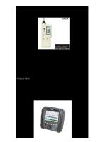
Modern machine diagnosis
Measuring machine condition with a modern measuring Instrument (VT-60)
11
Balancing and Diagnostic Systems
Measurement types for mechanical vibrations Vibration displacement „s“
in µm or mil
= deviation of measured point from rest position
Vibration velocity „v“
in mm/s or ips
= velocity with which measured point moves about rest position
Vibration acceleration „a“
in m/s2 or g
= acceleration with which measured point moves about rest position
12
Balancing and Diagnostic Systems
Characteristics of composite vibrations • Narrow-band examination - Extraction into harmonic components (e.g. using a frequency analyser or tracking filters) • Broad-band examination - Through a summing formation in a defined frequency range (e.g. 10 …. 1,000 Hz)
13
Balancing and Diagnostic Systems
Amplitude data for vibration measurement
s
so = speak = sm Saverage
srms = seff t
speak-peak = spp
su = speak = sm
14
Balancing and Diagnostic Systems
Composite vibrations X
f t
X
2f
+
t
X
f + 2f
=
t
15
Balancing and Diagnostic Systems
Vibration in Time Domain vs. Frequency Domain x
x
t x
1
2
3
4
5
6
7
8
9 10 11
1
2
3
4
5
6
7
8
9
f
x t
x
10 11
f
x t
f 1
2
3
4
5
6
7
8
9
10
1116
Balancing and Diagnostic Systems
Influence of integration - Practice Vibration velocity spectrum
Vibration acceleration spectrum
Vibration displacement spectrum
17
Balancing and Diagnostic Systems
Selecting the measurement type Vibration displacement: Machines with speeds under approx. 600 rpm (10 Hz) Structural vibrations or Relative motions (shaft vibrations) in journal bearing machines of any speed
Vibration velocity: Vibrations in machines with speeds above 600 rpm (10 … 1,000 Hz)
Vibration acceleration: Vibrations with frequencies of interest above 2,000 Hz 18
Balancing and Diagnostic Systems
Vibration types in machines
Rotor Relative shaft vibrations
Absolute bearing vibrations
Bearing casing
Foundation 19
Balancing and Diagnostic Systems
Measuring Absolute Bearing Vibration General rules: Measurement points should be exactly defined and clearly marked Measuring points should be flat, clean and free of grease Loose paint and rusted surfaces should be cleaned or avoided Sensor must sit securely and not wobble Sensor and cable should not move during measurement 20
Balancing and Diagnostic Systems
Acceleration sensors
21
Balancing and Diagnostic Systems
Vibration velocity sensors
22
Balancing and Diagnostic Systems
Measuring Relative Shaft Vibration
A
45°
45°
B
23
Balancing and Diagnostic Systems
Eddy-current sensors Discrete type: Sensor with integral cable Calibrated extension cable Separate converter (oscillator)
Note: Cable lengths may not be altered! 24
Balancing and Diagnostic Systems
Eddy-current sensors Integrated type: Sensor with built-in oscillator and extension cable
Advice: Cable can be extended up to 1,000m in length Use in temperatures above 110°C is not possible
25
Balancing and Diagnostic Systems
Machine assessment using the Trend
26
Balancing and Diagnostic Systems
Machine assessment acc. to Standards and Guidelines A number of important Standards and Guidelines for rotating masses have been replaced during the last years by: DIN ISO 10816, parts 1 to 6 (absolute bearing vibrations) and DIN ISO 7919, parts 1 to 5 (relative shaft vibrations)
Reciprocating machines, including compressors, can be assessed according to DIN ISO 10816-6 (Reciprocating machines with > 100 kW) DIN ISO 8528-9 (Reciprocating internal combustion machines)
27
Balancing and Diagnostic Systems
Assessment of an electric motor acc. to ISO 10816
28
Balancing and Diagnostic Systems
Assessment zones Assessment zones according to DIN ISO 10816: Zone A:
Vibration in newly-installed machines
Zone B:
Machines may be operated for an unlimited time without restriction
Zone C:
Machines may be operated for a limited time
Zone D:
Vibrations are at a dangerous level and may cause damage to the machines 29
Balancing and Diagnostic Systems
DIN ISO 10816 Part 3, Group 2 Medium-sized machines with nominal power from 15 kW to 300 kW; Electrical machines with shaft height 160 mm ≤ H >315 mm
30
Balancing and Diagnostic Systems
Vibrations created in damaged bearings
31
Balancing and Diagnostic Systems
Impulses from a damaged bearing
32
Balancing and Diagnostic Systems
Damage frequencies in a rolling-element bearing ß ß d n N
D
Contact angle Rolling-element diameter No. of rolling elements Speed of shaft
Outer race damage
fo =
n•N 2 60
( 1 - d cos ß ) D
Inner race damage
fi =
n•N 2 60
(1+
Rolling-element damage
fr =
D•N d 60
(1- d D
Cage damage
fc =
N 2 60
( 1 - d cos ß ) D
d cos ß ) D
[ ]² cos² ß ) 33
Balancing and Diagnostic Systems
Damage frequencies in a rolling-element bearing
Ball-bearing SKF 6211 Dimensions
Damage frequencies
D = 77.5 mm
Fo = N/60 4.1 = 205 Hz
D = 14.3 mm
Fi = N/60 5.9 = 295 Hz
n = 10
Fr = N/60 5.2 = 260 Hz
ß = 0°
Fc = N/60 0.4 = 20 Hz
N = 3,000 rpm
34
Balancing and Diagnostic Systems
BCU signal process X
t
f
X
t
f BCU
X
t t 35
Balancing and Diagnostic Systems
Trend observation
Destruction
Example: Damage progress in a rolling-element bearing
36