![CLESTA EIII (Unit) Installation Manual [PDF]](https://pdfs.asia/img/200x200/clesta-eiii-unit-installation-manual.jpg)
8 0 7 MB
BOOK NO. 1E03DRD0 (4E) Printed in JAPAN 2014-07
DENTAL UNIT
INSTALLATION INSTRUCTIONS
H
IMPORTANT This manual provides installation instructions for the CLESTA eIII. The instructions contained in this booklet should be thoroughly read and understood before installing the chair and unit. After the installation has been completed, keep this manual in a safe place and refer to it for future maintenance.
TABLE OF CONTENTS
Page
1. Overview and Major Components----------------------------------------------------1
2. Dimensions and Specifications
3.
4. Necessary Tools--------------------------------------------------------------------------------6
5. Installation Instructions
6. Installation of Accessories and Optional Parts
7. Adjustment
8. Attach the Covers
9. Unit Flow Diagram------------------------------------------------------------------------- 22
2-1. Unit Section Specifications----------------------------------------------------------------1 2-2. Unit Section Dimensions-------------------------------------------------------------------2 Installation Requirements----------------------------------------------------------------3
5-1. Unit Section Unpacking--------------------------------------------------------------------6 5-2. Chair Section Preparation for Installations--------------------------------------------8 5-3. Unit Section Preparation for Installations---------------------------------------------8 5-4. Mounting Cuspidor Unit to the Chair--------------------------------------------------9 5-5. Installation of Utility Section (Plumbing)--------------------------------------------- 10 5-6. Electrical Connections in the Utility Section------------------------------------------ 12 5-7. Installation of the Dental Light---------------------------------------------------------- 13 6-1. Drain Cap and Basket Strainer--------------------------------------------------------- 14 6-2. Cupfiller Nozzle and Bowlflush Nozzle------------------------------------------------ 14 6-3. Assistant Arm Stopper--------------------------------------------------------------------- 14 6-4. DCI Syringe--------------------------------------------------------------------------------- 15 6-5. Attach the collar to the cart hose guide bracket (Cart type)---------------------- 16 6-6. Waste Receptacle (Optional)------------------------------------------------------------- 16 6-7. Film Viewer (Optional)-------------------------------------------------------------------- 16 6-8. Handpiece Flushout (Optional)---------------------------------------------------------- 17 6-9. Service Outlet (Water / Air)(Optional)------------------------------------------------- 17 6-10. Clean Water System (DCI Water Bottle)(Optional)------------------------------- 18 6-11. DCI Water Bottle Cover (Optional)--------------------------------------------------- 18 6-12. Monitor Bracket (Optional)------------------------------------------------------------ 19 7-1. Water and Air Stop Valves---------------------------------------------------------------- 20 7-2. Main Air Pressure-------------------------------------------------------------------------- 20 7-3. Main Water Pressure---------------------------------------------------------------------- 20 7-4. Handpiece Adjustment-------------------------------------------------------------------- 20 7-5. Instrument Holder Angle Adjustment---------------------------------------------- 21 8-1. Table Tray and Table Tray Mat--------------------------------------------------------- 21 8-2. Cuspidor Side Panel----------------------------------------------------------------------- 21 8-3. Mounting Bracket Cover----------------------------------------------------------------- 21
10. Unit Electrical Diagram
10-1. 100V Type---------------------------------------------------------------------------------- 23 10-2. 200V Type--------------------------------------------------------------------------------- 24
1. Overview and Major Components
Light Pole Dental Light H
Horizontal Arm Balance Arm
Cuspidor Unit Section Spittoon Bowl Assistant Control Panel
Doctor Unit Section
Cuspidor Control Panel
Doctor Unit Section
Assistant Arm
Dental Viewer
Assistant Holder Handpiece Holder
Utility Box
Lock Knob
Doctor Control Panel Doctor Table
Caster Cart Base
Foot Controller
Over the Patient Type
Cart Type
2. Dimensions and Specifications 2-1. Specifications
Rated power supply Fuse Air main pressure
Water main pressure Weight Dental Light
: AC110V 50/60Hz AC120V 50/60Hz AC220V 50/60Hz AC230V 50/60Hz AC240V 50Hz : 110V 120V ....... 10A/125V 220~240V ......... 5A/250V
: 0.45 ~ 0.5MPa
: 0.1 ~ 0.2MPa : 70kg (Without dental light) Over the Patient Type : 80.7kg (Without dental light) Cart Type
Usage environment
: AL-501 Dental light : 048 Dental light : Temperature +10ºC ~ +40ºC
Service Life
Air pressure 700 hPa ~ 1060 hPa : 10 Years
Humidity 30% ~ 75% Air pressure 700 hPa ~ 1060 hPa Transportation / Storage environment : Temperature -20ºC ~ +70ºC Humidity 10% ~ 95%
Equipment that is not suitable for use in air, flammable anesthetic gas, oxygen or nitrous oxide.
-1-
2-2. DIMENSIONS
Over the Patient Type
Cart Type
610
563
1210
1210
650
460
(Without Light Pole)
1050ࠤ1300
750ࠤ1000
743
1407
1407
829
(With Light Pole)
518
Unit : mm Dimensional tolerance: ±10%
-2-
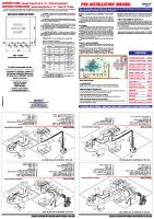
3. Installation Requirements
General Requirements (1) The contractor is to supply the necessary service and materials to complete the installation to the satisfaction of the dentists and the installation engineer. (2) This includes the supply and installation of the power source wires, air supply piping, water supply piping, suction piping including suction control wires and drain piping as noted on page 5 for installation position and plumbing layout. Setting Requirements (1) The CLESTA eIII dental unit comprises of a Chair section, Cuspidor unit section, Doctor table section and Dental light section. (2) The CLESTA eIII should be mounted taking the opening end of drain pipe (Installation reference point) into due consideration. (See page 5 for installation position and plumbing layout) (3) The area on which the CLESTA eIII is to be installed must have endurance force of 490kg/m2. (4) The installation position of the CLESTA eIII is shown in page 5 for installation position and plumbing layout as a recommended example. Piping and Plumbing Requirements (1) All piping and conduit for cables are to be laid under the floor and to come out from the floor in the positions shown in page 5 for installation position and plumbing layout. (2) The installation position and height from the floor of each pipe and cable conduit are shown in page 5 for installation position and plumbing layout. (3) The recommended sizes, materials and end piece are shown in list below. (4) Regarding installation of the vacuum pump and its connection to the main suction line, follow the specifications of central vacuum pump system manufacture's recommendation.
Item Material Size
End Piece
Compressed Air Supply Pipe
Shock Resistance P.V.C. Pipe HI-13
Out. Dia.18mm In. Dia. 13mm
PT1/2
Water Supply Pipe
Shock Resistance P.V.C. Pipe HI-13
Out. Dia.18mm In. Dia. 13mm
PT1/2
Suction Pipe P.V.C. Pipe VP-20
Out Dia. 26mm IN. Dia. 20mm
Drain Pipe P.V.C. Pipe VP-50
Out. Dia.58mm In. Dia. 50mm
Power Supply Cable Conduit
P.V.C. VE-16
In. Dia. 16mm
Vacuum Control Wire Conduit
P.V.C. VE-16
In. Dia. 16mm
Note : The suction pipe and drain pipe should be laid under the floor with an inclination of 1/200 - 1/400. Air vacuum type does not require suction pipe, vacuum control wire and its conduit.
-3-
Air Supply Requirements (1) Compressed air to be supplied should be filtered. Dirt and moisture in the air may cause trouble in unit air system.
(2) Air Pressure Regulate the outlet air pressure of the compressor to the utility box at 0.5-0.7MPa (5.0-7.0kg/cm2)
and the air pressure should be kept between 0.45-0.5MPa (4.5-5.0kg/cm2) in the utility box at any time. (3) Compressed Air Supply Capacity Central vacuum type . . . at least 60 l/min. Air vacuum type . . . at least 100 l/min
Water Supply Requirements (1) The supply water should be clean. Dirty water may cause trouble in unit water line. (2) Regulate the water pressure of the water supply to the utility box at 0.2-0.4MPa (2.0-4.0kg/cm2) for
operating unit efficiently. The water pressure should be kept between 0.1-0.2Mpa (1.0-2.0kg/ cm2) in the utility box at any time.
(3) Amount of water Central saliva ejector type . . . at least 5 l/min. Water saliva ejector type . . . at least 7 l/min
Electric Supply Requirements (1) The connection of the power supply cable is to be carried out in accordance with the local electrical
regulation. (2) Capacity of the power supply (Include the CLESTA eIII Chair) 110/120V Type Single Phase 50/60 Hz : 10A 220V Type 230V Type 240V Type
Single Phase 50/60 Hz : 5A Single Phase 50/60 Hz : 5A Single Phase 50Hz
: 5A
(3) Power supply line should be provided with fuses or circuit breaker in accordance with power consumption. (4) The earth wire (ground wire) should be proved in the utility box.
(5) All cables should have at least 500mm surplus from the floor so that they are long enough to be connected to the terminals in the utility box.
-4-
Unit : mm Dimensional tolerance: ±10% Place the Utility Box Horizontally (Front of the Chair Base)
2700 min.528
min.300
410
min.1000
70
Drain (Installation reference point)
min.1000
min.800
Vacuum Pipe
Base Plate min.300
min.988
Base Plate
160
300
2700
Drain (Installation reference point)
Partition
Place the Utility box Vertically (Under the Cuspidor)
Air Supply
70
135 220
70
70
110
55
280
220 135 110 55
Air Supply
Power Source Water Supply
min.800
280
Vacuum Operating Wire Drain (Installation
Vacuum Pipe
Drain (Installation
Water Supply
reference point)
Power Source
reference point)
Floor Line
Air Supply Vacuum Pipe Power Source
Air Supply
Drain (Installation reference point) Vacuum Operating Wire
20 ± 5
30 ± 5
Water Supply
20
30
30 40
40
PT1/2
40
20
Water Supply Vacuum Pipe
40 ± 5
Drain (Installation reference point)
PT1/2
40 ± 5
Power Source • Vacuum Operating Wire
40
Floor Line
30
Vacuum Operating Wire
Detail of piping size Dimensional tolerance : ±5mm Water Supply Air Supply
Vacuum Pipe
Power Source Vacuum Operating Wire
Drain
Air vacuum type does not need vacuum pipe, vacuum operating wires and conduit. Installation Position and Plumbing Layout (Central Vacuum Type)
-5-
4. Necessary Tools for installation
The following tools are necessary to assembling this product.
No.
Name of Tools
Qty.
1
Phillips head screwdrivers #2~ #4
2
Flat head screwdriver
1 pc.
3
Precision screwdriver set (Phillips head / Flat head)
1 set
4
Adjustable wrench
1 pc.
5
Water pump pliers
1 pc.
6
Open end wrench set (5.5 ~ 24mm)
1 set
7
Allen wrench set (1.5 ~ 8mm)
1 set
8
Socket wrench set (8~22mm)
1 set
9
Long nose pliers
1 pc.
10
Diagonal pliers
1 pc.
11
Wire stripper
1 pc.
12
Wire crimp tool
1 pc.
13
Blade knife
1 pc.
1 pc./each
5. Installation Instructions
Mats
aM st
aM st
5-1. Unit Section Unpacking 1. Remove all wood screws fixing the carton to the pallet and lift up to remove the carton.
Wood screw
-6-
2. Open the boxes that contain parts and check the contents of each box with the accessory parts list
attached to the parts box and with below list. Make sure to use provided parts such as screws, joints, and stainless flexible pipes that are used to mount the chair or for plumbing in the utility box.
Also, check the necessary parts for installing the option by referring to the below list. Refer to the section 6: Installation of Accessories and Optional Parts instruction.
There are many small parts for optional kit that are packed in the plastic bag with option name label.
Utility Box (Plumbing) Parts / Unit fixing parts Description
No.
Purpose / Location of use
Qty.
1
Spring washer M10
Unit fixing
4 pcs.
2
Nut M10
Unit fixing
4 pcs.
3
Hex head bolt M10 x 30
Unit leveling
4 pcs.
4
Wood screw M3.5 x 20
Utility box fixing
4 pcs.
5
Vacuum elbow
Utility box plumbing (Central vacuum)
1 pc.
6
Drain elbow
Utility box plumbing (Central vacuum)
1 pc.
7
Drain joint (Optional)
Utility box plumbing (Air vacuum)
1 pc.
8
Drain bush (Optional)
Utility box plumbing (Insert to drain pipe)
1 pc.
9
Stop valve (Water / Air)
Utility box plumbing
2 pcs.
10
Stainless flexible pipe
Utility box plumbing
2 pcs.
Unit Parts No.
Description
Purpose / Location of use
Qty.
1
Waste receptacle & Bracket
Waste receptacle
1 pc./each
2
Light pole washer & Connectors (3 pcs.)
Dental light
1 pc./each
3
Cover hose clamp, pan head screw M3 x 16, Nut M3
Syringe (Assistant side)
1 pc./each
4
Collar, Pan head screw M4 x 35, Cap nut
Cart hose guide bracket
1 pc./each
5
Flat head screw M5 x 15
Table tray (Large size)
6
Assistant arm stopper, M10 Spring washer
Mounting bracket
4 pcs. 1 pc./each
Optional Parts No. 1
Description
Purpose / Location of use
Monitor rotation shaft, Washer, Bottom cover, Truss screw M4 x 12 (2 pcs.), Set screw M6 x 8 (2 pcs.), Hex cap bolt M5 x 8 (2 pcs)
Monitor bracket
Qty. 1 set
Optional Kit No.
Description
Purpose / Location of use
Qty.
1
EMS Scaler assembling Kit
EMS scaler
1 set
2
SP-4055 (P-Max) scaler assembling lit
SP-4055 (P-Max) scaler
1 set
3
SP-4055 NEWTRON scaler assembling kit
SP-4055 NEWTRON scaler
1 set
4
VARIOS170 scaler assembling kit
VARIOS170 scaler
1 set
5
CAVITRON scaler assembling kit
CAVITRON scaler
1 set
6
Handpiece flush-out assembling kit
Handpiece flush-out
1 set
7
Air service outlet assembling kit
Air service outlet
1 set
8
Water service outlet assembling kit
Water service outlet
1 set
9
DURR CS1 assembling kit
DURR CS1
1 set
-7-
5-2. Chair Section Preparation 1. Remove the carriage bolt from the chair. * Refer to the chair installation manual for preparation of the chair. * Do not attach the backrest and seat section until the unit installation has been completed.
Carriage bolt (with red tag)
CAUTION
Be sure to remove the carriage bolt from the chair before lift the chair by upper structure. This could cause damage to the chair if operate the chair without removing the carriage bolt.
5-3. Unit Section Preparation 1. Remove two wood screws fixing the utility box to the pallet.
2. Remove four cuspidor unit fixing screws (M10 x 65 flat head screw) and hold the cuspidor unit. Four flat head screws are used when fix the cuspidor unit to the chair.
M10 x 65 Flat head screw
-8-
5-4. Mounting Cuspidor Unit to the Chair
1. Raise the dental chair to the highest position.
2. Mount the cuspidor unit on the mounting bracket of the chair and fix with four M10 x 65 flat head screw which fixed cuspidor unit to the pallet, and M10 spring washer, M10 Nut. Adjust the level of the cuspidor unit with four M10 x 30 level adjustment hex head bolt as needed.
M10 x 65 Flat head screw Chair side mounting bracket Cuspidor side mounting bracket M10 Spring washer M10 Nut
M10 x 30 Hex head bolt
After mounted the cuspidor unit on the chair, please confirm that the cuspidor unit does not hit to the utility box when move the chair to lowest position.
-9-
5-5. Installation of Utility Box (Plumbing)
1. Install the water stop valve and the air stop valve to each supply pipe.
The positioning of the stop valves are shown in page 5 for Installation Position and Plumbing Layout. 2. Fix the utility box to the floor with four M3.5 x 20 wood screws. M3.5 x 20 Wood Screws (4 pcs.)
3. Drain Hose and Vacuum Hose Connection
- Central Vacuum Type 1) Cut the drain hose and vacuum hoses at suitable length and connect them to each elbow with plastic glue. Note : The Drain hose should be sealed with silicone sealant or taping. 2) Insert the drain hose elbow and vacuum hose elbow into each pipe.
Note : The Drain pipe should be sealed with silicone sealant or taping.
Attaching Drain Bushing (Optional) to the Drain Pipe is desirable, and Drain Elbow should be bonded firmly into the Drain Pipe. Connect with plastic glue
Drain Hose
Vacuum Hose Vacuum Elbow
Drain Elbow
Connect with plastic glue Drain Bush (Optional)
Vacuum Pipe
Drain Pipe
- Air Vacuum Type 1) Cut the drain hose and vacuum hoses at suitable length and connect them to drain joint (Optional) with plastic glue (Pipe solvent). Note : The Drain hose should be sealed with silicone sealant or taping. 2) Insert the drain joint (Optional) into drain pipe.
Note : The Drain pipe should be sealed with silicone sealant or taping.
Attaching drain bushing (Optional) to the drain pipe is desirable, and drain joint should be bonded firmly into the drain pipe.
Drain Hose
Vacuum Hose Connect with plastic glue
Drain Joint (Optional) Drain Bush (Optional) Drain Pipe
- 10 -
4. Water and Air Supply Line Connection 1) Bend each stainless flexible pipe to a suitable angle for easily connectable between water/air stop valves and water/air filters. (See figure below)
Air filter
Air stop valve
Be careful not to bend flexible pipe to acute angle. (Less than radius of 50mm)
Drain elbow
Water filter
Vacuum elbow
Water stop valve
2) Connect the stainless flexible pipe with rubber seal to water/air stop valves and tighten it securely using the adjustable wrench. Be careful not to pinch the rubber seal when connect it. Adjustable wrench
Rubber seal Stainless flexible pipe Stop valve
3) Connect the stainless flexible pipe with rubber seal to filters and tighten it securely using the adjustable wrench and water pump pliers. Be careful not to pinch the rubber seal when connect it. Adjustable wrench
Rubber seal
Water pump pliers
Stainless Flexible Pipe
Stainless flexible pipe
Filter
Filter
5. Cart Type Seal (Packing) 1) Connect the umbilical hose to the utility connect the tubings from cuspidor unit to the utility Stop Valvebox and parts. For air vacuum type, does not have the green turbing (φ4 x 6). Yellow (4 x 6)
Blue (2 x 4)
Black (1.2 x 2)
Blue (2 x 4) with barb fitting
Black (1.2 x 2) with barb fitting
Umbilical hose
Tubings from cuspidor unit Tubings from doctor table Blue (6.5 x 10)
Orange (2 x 3.7) Green (4 x 6)
Air switch (Vacuum operating) Air switch (Main switch)
2) Connect the blue (2 x 4) tubing with barb fitting and black (1.2 x 2) tubing with barb fitting.
Blue tubing • • • Small size master valve in the cuspidor ~ Doctor table water line Black tubing • • • Shuttle valve of the cupfiller in the cuspidor ~ Cupfiller switch of the doctor table
- 11 -
5-6. Electrical Connections in the Utility Section
* Be sure turn off the breaker of the power source line and main switch before connect the wirings. Be sure to connect the earth wire into the utility frame. 1. Connect the central vacuum operating wires to the terminal block. (This connection is central vacuum type only. The Air vacuum type does not have this connection.) * How to connect terminal block 1) Cut the vacuum operating wires at suitable length with a diagonal pliers. 2) Cut the exterior insulation of the vacuum operating wires about 10mm using the wire stripper. 3) While pressing the slot of the terminal with a small head flat head screwdriver, insert the wire to the terminal and release the screwdriver. Make sure that the wire is connected securely. Cut the wires with diagonal pliers
Wires (Yellow)
Vacuum Operating wire Strip the wires with wire stripper
10mm
Flat head screwdriver Terminal block
Wire
2. Connection of the chair power supply cable -100V TypeConnect the plug of the chair power supply cable to socket in the utility box. Connect the unit side connectors (4P and 9P) the chair side connectors (4P and 9P) in the utility section. -200V TypeConnect the chair power supply cable to the terminal block in the utility box. Connect the earth wire of the power supply cable onto the utility frame with M4 screw. (M4 screw is attached on the frame) Connect the unit side connectors (4P and 9P) the chair side connectors (4P and 9P) in the utility section. Earth Black
Black Black
Black White
White White
White
Brown Black Light blue White
Light blue
4P Connector (Signal line for chair safety)
9P Connector (Chair operating wire)
Brown
Chair power supply cable Socket
9P Connector (Chair operating wire)
Chair power supply cable with plug
-100V Type-
4P Connector (Signal line for chair safety)
-200V Type-
3. Connect the unit power supply plug into the suitable power supply line in the utility section. The power supply plug may not be able to use depending on the countries. Use a plug adapter or replace a plug to plug it into the power supply line.
Unit power supply plug
- 12 -
5-7. Installation of the Dental Light
1. Put washer (φ28.8 x φ40.5) on the light pole. Pass the light cable through the light pole and
attach the dental light section to the light pole. Fix the light section and light pole with M5 x 8 set screws using the 5mm allen wrench. (Set screws are attached onto the light pole) Dental light section Light cable
Washer
H
Set screw M5 x 8 (4 pcs.)
Light pole
2.Connect the wires from the dental light and wires from the cuspidor unit one by one with connectors using the long nose pliers. See the figure below for color of the wires from the dental light and the unit. Insert the light pole to the main post and fix with two M6 x 18 and
two M6 x 8 set screws using the M6 allen wrench (Set screws are attached onto the main post).
From dental light
Light Blue (Blue)
Brown (Brown)
Yellow/Green Earth
White (Light Blue)
Black (Brown)
Yellow/Green Earth
Cable from dental Light
H
From unit
Connector Wires from dental light
Connector
Long nose pliers
Insert the wires into groove of the connector. Pinch the inner cover with long nose pliers.
Cable from unit
Wires from cuspidor unit
Groove
Set Screw M6 x 18 (2 pcs.)
Main post Set screw M6 x 8 (2 pcs.)
Hold the outer cover of the connector and attach it to the opposite side groove.
- 13 -
6. Installation of Accessories and Optional Parts
* Refer to the Final Assembly File (FAF) for installing the handpiece and separator.
* Do not attach the covers until the installation has been completed (Wiring, tubing connection and
accessories, optional parts installation). The small size table tray and the cuspidor side panels are attached to the unit at the factory. Remove the small size table tray and cuspidor side panel as follows.
Table chassis
Side panel fixing screw Cuspidor side panel Cuspidor side panel
M5 x 15 Flat head screw
Table tray (Small size)
Loosen the side panel fixing screw by flat head screwdriver and open it outward Flat head screwdriver
- How to open the table tray -
- How to open the cuspidor side panel 6-1. Drain Cap and Basket Strainer
Fit the drain cap and the basket strainer in the spittoon bowl. Drain cap Basket strainer
Spittoon bowl
6-2. Cupfiller Nozzle and Bowlflush Nozzle
Insert the cupfiller nozzle and the bowlflush nozzle to the spittoon bowl and tighten each nut by hand. Nut
Cupfiller nozzle
Bowlflush nozzle
6-3. Assistant Arm Stopper
The assistant arm stopper is not attached to the mounting bracket due to the packaging restrictions. Attach the assistant arm stopper by using the 17mm spanner until M10 spring washer becomes flat. Be careful not to over tighten the screw, it may break the screw.
M10 Spring washer Assistant arm stopper
- 14 -
6-4. DCI Syringe - Doctor Table side -
1. Unscrew the six M4 x 12 sems screws and remove the membrane panel from the doctor table.
2. Pass the syringe tubing through to the table chassis and insert the syringe tubing to the cover hose clamp. 3. Connect the syringe tubings to the needle valve (Water and Air) as shown in figure. * Air tubing and water tubing are both gray color. Connect the air supply to the syringe tubing to confirm which is the air line before connect the needle valve.
4. Tighten the M3 x 16 pan head screw with M3 nut of the cover hose clamp to fix the syringe hose. 5. Set the syringe into the handpiece holder. 6. Fix the membrane panel on the table with same screws. M3 x 16 Pan head screw Membrane panel
M3 Nut
Syringe Needle Valve for Syringe
Water (Blue cap)
Gray
Air (Yellow cap)
Cover hose clamp Connected in factory
Water Needle valve for syringe
Table chassis M4 x 12 Sems screw
Connected in factory
Air
- Assistant side -
1. Pass the syringe tubings through the hole of the cuspidor front panel and fix it with cover hose clamp, M3 x 16 pan head screw and M3 nut.
2. Connect the syringe tubings to the needle valve (Water and Air) as shown in figure.
* Air tubing and water tubing are both gray color. Connect the air supply to the syringe tubing to confirm which is the air line before connect the needle valve.
3. Tighten the M3 x 16 pan head screw with M3 nut of the cover hose clamp to fix the syringe hose. 4. Set the DCI syringe into the assistant holder.
M3 Nut
Cover Hose clamp
Syringe Tube
Gray M3 x 16 Pan head screw
Water Needle valve for syringe Air Water (Blue cap)
Needle valve Air for syringe (Yellow cap)
- 15 -
Connected in factory
Connected in factory
Master valve set (Small size)
6-5. Attach the Collar to the Cart Hose Guide Bracket (Cart type)
Due to the packing, did not attach the following collar to the guide bracket at the factory.
Attach the collar to the cart hose guide bracket with M4 x 35 pan head screw and cap nut using the #2 phillips head screwdriver.
M4 x 35 Pan head screw
Collar
Cap nut
6-6. Waste Receptacle (Optional)
Fix the waste receptacle bracket to the doctor table with M10 nut using the adjustable wrench. Put the waste receptacle into the waste receptacle bracket.
Adjustable Wrench
Nut
Waste Receptacle
Waste Receptacle Bracket
6-7. Film Viewer (Optional)
1. Remove the two M4 x 15 sems screws from under the table chassis using the #2 phillips head screwdriver. 2. Pass the film viewer cable through to the table chassis as shown in figure. Fix the film viewer to the table chassis with two M4 x 15 sems screws. Follow the same procedures for panorama viewer. Cable
Film viewer
Cable
M4 x 15 3A Sems screw Table chassis
- 16 -
M4 x 15 3A Sems screw
6-8. Handpiece Flushout (Optional)
* Make sure to use the flushout assembling kit. Fix the flushout switch to the table chassis.
Direction of the flushout switch is on direction for front side and off direction for rear side of the table chassis.(See figure) Keep the dismounted parts after replaced from kit installation for future maintenance
Flushout switch
To be connected on site
Flushout switch
Connected at factory
ON (Front Side)
Air manifold
Table chassis Washer, Nut
(Come with flushout switch)
Clear ( 2 x 3.7 200mm)
Flushout switch fixing hole
Replace plug for 1/4 barb fitting
Pullback Valve
Gray ( 2 x 3.7 200mm)
(Rear Side) OFF
Gray ( 2 x 3.7 200mm)
Air
Replace 1/8 barb fitting for plug
Gray ( 2 x 3.7 200mm)
Shuttle Valve Coolant air (From foot controller)
Gray
T Joint
W P C D
Gray ( 2 x 3.7 200mm)
Auto select valve
6-9. Service Outlet (Water / Air)(Optional)
* Make sure to use the service outlet assembling kit (Water/Air).
Fix the service outlet and needle valve on the cuspidor panel and connect the tubings as shown on the following figure.
Keep the dismounted parts after replaced from kit installation for future maintenance. To be connected on site Connected at factory
To be connected on site Connected at factory Replace plug for 1/4 barb fitting
Needle Valve (Water) Needle Valve (Water)
Cuspidor panel
Blue ( 4x 6 200mm)
Cut the air tubing and connect with T-Joint
Yellow ( 4 x 6 350mm)
Blue ( 4x 6 350mm)
Service outlet (Water) Remove the Hole Plug
Service outlet (Water)
Service outlet (Air)
T-joint
Service outlet (Air) Yellow ( 4 x 6 400mm)
Service outlet (Air)
- 17 -
Master Valve set (Small)
Air
Master Valve set (Small)
* With clean water system specifications
6-10. Clean Water System (DCI Water Bottle)(Optional)
Fix the water bottle bracket on the main post with two M4 x 10 sems screws. Connect the tubings as shown on the following figure.
Main post Water bottle bracket Sems screw M4 x 10 Tubings from water bottle bracket (Gray/Red/Blue)
Water bottle
Master Valve Set (Small) To be connected on side Connected at factory ON/OFF Valve
Grey 1/4”
Air Regulator
Blue 1/4”
City/Bottle Selector Valve
Air manifold
Syringe flow control valve
Water bottle
Water manifold
Master valve set (Small)
Blue 2×4 Red 1/4” Blue 1/4”
Blue 2×4
Dr.Table water line
Gray 1/4”
T-Joint
6-11. DCI Water Bottle Cover (Optional)
Remove the two water bottle fixing screws from the water bottle bracket. Attach the water bottle cover on the water bottle bracket and confirm that hole of the water bottle cover is fit to the pressure gauge. Fix the water bottle cover with two water bottle fixing screws.
Water bottle fixing screw Pressure gauge Water bottle cover Hole for pressure gauge
- 18 -
Water bottle fixing screw
6-12. Monitor Bracket (Optional)
1. Insert the monitor bracket bottom cover and fix the two M5 x 8 cap screws (stopper for monitor bracket) to the light pole, then insert the monitor bracket to the light pole.
2. Put washer on the monitor bracket. Pass the monitor cable through the monitor bracket and the light pole, then insert the monitor rotation shaft to the monitor bracket
3. Fix the monitor bracket to the light post with two M6 x 8 set screws and fix the monitor bracket bottom cover to the monitor bracket with two M4 x 12 truss screws.
Light pole
Monitor bracket
Monitor rotation shaft
Monitor Cable
Washer M5 x 8 (2pcs.) Cap screw Monitor bracket bottom cover
M6 x 8 (2pcs.) Set screw
Main post
Hole on the Mounting bracket
- 19 -
M4 x 12 (2pcs.) Truss screw
7. Adjustment
7-1. Water and Air Stop Valves
Open the water stop valve and the air stop valve counterclockwise in the utility section.
Turn on the master switch and check that water and air are not leaking.
7-2. Main Air Pressure
The main air pressure has been adjusted in the factory. Confirm that the main air pressure is at 0.45-0.5MPa by the main air pressure gauge.
The main air pressure can be regulated by the main air regulator in the utility section.
7-3. Main Water Pressure
The main water pressure has been adjusted in the factory. Confirm the main water pressure is at 0.1-0.2MPa by the main water pressure gauge.
The main water pressure can be regulated by the main water regulator in the utility section. Main switch
Air stop valve
Main air regulator
Main air pressure gauge Main water pressure gauge Knob
Knob
Under the doctor table
Decrease
Main water regulator
Decrease Increase
Increase
Water stop valve Main water regulator
7-4. Handpiece Adjustment
Main air regulator
Pull the knob and adjust the pressure as shown in the drawing
1. Handpiece Drive Air Adjustment
Adjustment of each handpiece drive air can be made by the screw on the auto select valve. Turning the drive air screw clockwise to decrease the flow volume and turning counterclockwise to increases the flow volume. Pick up the handpiece from holder and depress the foot controller, adjust the drive air pressure in according with the handpiece manufacture’s recommendation. Drive air pressure is indicated on the handpiece pressure gauge located on the right side of the table.
2.Handpiece Coolant Air Adjustment
Handpiece coolant air adjustment screws are provided for individual adjustment of handpiece coolant air. Turning a handpiece coolant air adjustment screw counterclockwise increases flow volume and turning clockwise decreases. * Position of adjustment screw corresponds to the position of the handpiece holder.
* Be careful, the adjustment knob may come off if the adjustment knob turning counter clockwise excessively.
* Drive air and coolant air has been adjusted in factory. Do not change the setting under normal conditions. Coolant air screw
Drive air screw Handpiece holder
Syringe holder
HP1 HP2 HP3 HP4
Handpiece pressure gauge
- 20 -
HP1
HP2 HP3
HP4
7-5. Instrument Holder Angle Adjustment
Loosen the adjustment screw located on the underside of the holder support arm. Set the holder at the client's favorite position and fix by tightening the adjustment screw using the 5mm allen wrench. Holder angle can be adjusted between 20 to 30 degrees.
Instrument holder
Adjustment screw
8. Attach the Cover
* After the wirings, tubings and installation of the accessary parts has been completed, attach the cover to the unit.
8-1. Table Tray and Table Tray Mat
Fix the table tray to the table chassis with four M5 x 15 flat head screws. Place the table tray mat on the table tray. Follow the same procedure for the small size table tray. Table tray mat (Large size)
Table tray mat (Small size)
M5 x 15 Flat head screw
Table chassis
Table tray (Small size)
Table tray (Large size)
8-2. Cuspidor Side Panel
Attach the cuspidor side panel and fix it with cover fixing screws using the flat head screwdriver. Side panel fixing screw Cuspidor side panel
Cuspidor side panel
Flat head screwdriver
8-3. Mounting Bracket Cover
Attach the mounting bracket cover on the mounting bracket.
Mounting bracket cover
Mounting bracket
- 21 -
9. Unit Flow Diagram (Central Vacuum, Central Saliva Ejector, Clean Water System, Service Outlet, Flushout Switch Specifications) Balance Arm Air Brake
HP3
HP4
Air Brake Switch
Air Motor
Turbine (Optic)
Cupfiller Switch
Doctor Table Section
Micro Pilot Valve (NC.)
Micro Pilot Valve (NC.)
HP2
HP3 EXH.
EXH.
Micro Pilot Valve (NC.)
Micro Pilot Valve (NC.)
HP4
EXH.
Master Switch
HP1
HP2
Turbine (Optic)
Scaler (Optic)
Syringe (3 Way Syringe)
EXH.
EXH.
HP1 EXH.
Oil Mist Separator EXH.
Micro Pilot Valve (NC.) Syringe Water Flow Control Syringe Air Valve Flow Control Valve
Air Manifold
HP4
Spray Water Control Valve
HP2 Optic Turbine HP3 Optic Turbine HP4 Optic Scaler
HP3
HP2
Flushout Sw
HP1
Air Switch for HP Optic Cupfiller Sw. Shuttle Valve
Main In Main Out
Pull Back Valve
Air Water
Auto Select Valve
Coolant Air
Handpiece Pressure Gauge
Exhaust Valve
Drive Air
Scaler ON-OFF Switch
Inline Filter
Chip Air
Bowl Flush Nozzle
Spittoon Bowl
Syringe
EXH. Shuttle Valve
Micro Pilot Valve (NO.)
Cupfiller Switch Bowlflush Switch
Water Heater
Exhaust Valve
Micro Pilot Valve (NC.)
Saliva Ejector Handpiece Micro Pilot Valve (NO.)
Cupfiller Nozzle
Exhaust Valve
EXH.
Vacuum Handpiece
Cuspidor Section
Chamber
Shuttle Valve Exhaust Air Flow Control Valve
Syringe Air Flow Control Valve
Syringe Water Flow Control Valve
ON/OFF Valve
Air Regulator
Shuttle Valve
City/Bottle Select Valve
Water Bottle
EXH.
Flow Adjustable Check Valve
Vacuum Line Valve Control Knob for Water Service Outlet
Small Size Master Valve
Water Service Outlet
Main Water Pressure Gauge
䠆
䠄
Main Air Pressure Gauge 䠈
䠆 䠊 䠃䠂
䠄
䠈 䠊 䠃䠂
Utility Box Section
Main Air Regulator
Main Water Master Valve
Air Filter (50 µ) Air Stop Valve
Air Switch Air Switch Air Switch for Vacuum for Chair for Main Safety Switch
Main Water Regulator
Foot Controller
Air
Main Air Master Valve
Water Stop Valve Vacuum
Drain
- 22 -
Water
Drain Valve Water Filter (150 µ)
10. Unit Electrical Diagram
10-1. 100V Type (Sensor Cupfiller, Optic Turbine, Electric Scaler Specifications
LED ON/OFF
Black Yellow Green
LED Output VR
LED Output
1
3 2kΩ Scaler LED Light Adjustment Volume
Blue COM
Turbine (Optic)
Red
HP3
NC NO
(Optional) Scaler (Optic)
Red
HP4
Brown Brown Brown Brown Black Black Black Red White Red
Black Red
2
Dental Viewer (Optional)
Ferrite Core (Accessory from Newtron)
HP3 Air Switch Turbine Light
0
1
9
Membrane Switch
Scaler ON/OFF Air Switch
Red Gray Purple Black
LP
NC NO
COM
Black
Blue White
Black Black Red Red Orange Black
White Brown
1
2
Scaler Output Control Volume
3
Green
1
Green Yellow Green
Blue White
Black Black Black Black
White
1
Turbine (Optic)
SP4055 NEWTRON Module
HP2
Brown
AC24V
PERIO SCALING ENDO
White Black Blue
Red Black
Black Red Brown
Brown Red Orange Yellow Green Blue Purple Gray Black
Scaler Mode Select Switch LED Drive Board
HP2 Air Switch Turbine Light
Gray NC Blue NO
Table Earth Yellow/Green
Red
NC NO
Red Black
OFF
Cupfiller SV.
Light Pack ON/OFF Switch
Black Red
ON
Light Pack PCB.
Water Heater PCB.
Sensor Cupfiller (Optional)
Pink COM
Dental Light Power Line
1
2
Red Black Blue Purple
1
3
CN3 White Black Yellow/Green
CN2
ON OFF
Red Black Blue Purple
Heater Switch
Yellow N.O. Orange COM.
Purple
Blue
CN1
Water Heater 24V
4
1
Blue White Brown Brown White White
Red Pink
Blue Black Brown
Yellow-Green Blue
Yellow-Green Purple Red Black
Blue COM
Sensor Cupfiller PCB. Cuspidor Earth Yellow/Green
Chair Safety Switch.
White : Black (Cuspidor Spare Line) 0V.Purple / 14V.Blue (Cuspidor) 0V.Black / 24V.Red (Cuspidor)
Unit Power Supply Blue Purple 0V
0V
14V
1 2
Black
1 2
White
Black Yellow
1 2 3 4
0V.Black / 24V.Red (Table)
Blue Blue Blue Black Black Red Brown
Black
1 2
Black Black Black Red Red
6
Yellow Yellow
Black
Black
White
3 4 5
White Black White Black White White White Black
Main Switch
Black 4 COM. Black 6 N.O. Yellow 2 N.O. Yellow 1 COM.
White Black White
White Black
White 5 N.O. White 3 COM.
Blue
(White,Black, Yellow/Green)
Vacuum Operating Wire
Vacuum Switch White 1
Black Brown Red
Black 4
0V 20V 24V
White 3 Blue Blue
(Primary) (10A)
0V 14V
Fuse
Outlet for Chair Power Supply Yellow/Green
Black 1
(Secondary 24V) (10A/1A/3A)
Black 2
Fuse
Blue
1
3:Orange / 4:Yellow
110V
100V
White
1:Brown / 2:Red / 3:Orange 4:Yellow / 5:Green / 6:Blue 7:Purple / 8:Gray / 9:Black
0V
2
To Chair 9P Connector Chair Operating Line
Chair Safety Line
Unit Transformer
Black
(Secondary 14V) (2.5A) Blue (Used with 10A Transformer)
Chair Power Supply Cable
Black 2
Fuse
Yellow/Green
4P Connector
U-BOX Earth Yellow
Ferrite Core for SP4055 Newtron
- 23 -
10-2. 200V Type (Sensor Cupfiller, Optic Turbine, Electric Scaler Specifications
Brown Green
COM
LP
0
1
2
Membrane Switch
Turbine (Optic)
HP3
HP2
Turbine (Optic)
(Optional) Scaler (Optic)
Brown Green
Table Earth
Brown
COM
Black
Brown Blue
B
Yellow/Green
NC NO
OUT
Dental Light Power Line
2
White Black Yellow/Green
Light Pack ON/OFF Switch
Red Black
IN
Cupfiller SV. Black Red
OFF
Brown Blue
ON
Water Heater PCB.
Sensor Cupfiller (Optional)
1
3
CN3
Chair Power Supply Cable Yellow N.O. Orange COM.
CN1
1
Purple
Blue
(Brown,Light Blue,Yellow/Green)
1 CN2
Blue White Brown Brown White White
Blue rown
Blue Black Brown
Blue
Yellow-Green
Yellow-Green Purple Red Black
HP2 Air Switch Turbine Light
Terminal Block for LED
Light Pack PCB.
Scaler ON/OFF Air Switch
Brown Brown Brown Brown Black Gray Black Black White White Red Red
Red
HP3 Air Switch Turbine Light
Gray NC Blue NO Blue COM
NC NO
Black
Black
NC NO
ON OFF
Red Black
Red Black
Blue Purple
Blue Purple
Heater Switch
Water Heater 24V
4
Sensor Cupfiller PCB.
Chair Safety Switch.
Cuspidor Earth
Yellow/Green White : Black (Cuspidor Spare Line) 0V.Purple / 14V.Blue (Cuspidor) 0V.Black / 24V.Red (Cuspidor)
Unit Power Supply
(Brown,Light Blue, Yellow/Green) Blue Purple Blue Black Black Black Red Red
Yellow Yellow
14V
Black
Vacuum Switch White 1
Black Brown Red
Black 4
0V 20V 24V
White 3 Blue Blue
(Primary) (5A)
0V 14V
Fuse
Black 2
Blue
1
Blue
2
To Chair Chair Operating Line
1:Brown / 2:Red / 3:Orange 4:Yellow / 5:Green / 6:Blue 7:Purple / 8:Gray / 9:Black
Unit Transformer
9P Connector Yellow/Green
4P Connector
U-BOX Earth
White
(Secondary 14V) (2.5A) (Used with 10A Transformer)
0V
Black 2
Fuse
230V 240V
Black 1
(Secondary 24V) (10A/1A/4A)
Black
Fuse
Yellow
Chair Safety Line
3:Orange / 4:Yellow
- 24 -
23
0V
Blue Blue Blue Black Black Red Brown
White Black
Black
0V
Black
Brown Yellow
White
White
Light Blue
White Black White Black
Black 4 COM. Black 6 N.O. Yellow 2 N.O. Yellow 1 COM.
White Black White
Brown
White 5 N.O. White 3 COM.
Light Blue
Vacuum Operating Wire
Main Switch
9
Dental Viewer (Optional) VARIOS 170 Control PCB.
Blue COM
1
Scaler Output Control Volume
3
Purple
Red Gray Purple
Red
2
1
Gray Orange White
HP4
White Gray
1 2 3 4 5 6 7 8 9 10111213 14
White Orange Gray Red Yellow Blue Brown Purple Black Black
White Orange Gray Red Yellow Blue Brown Purple Black Black
1
123
Green Brown White Orange Gray Red Yellow Blue Purple Black
PERIO SCALING ENDO
Red Black
Red Black
Brown Red Orange Yellow Green Blue Purple Gray Black
Scaler Mode Select Switch Yellow Black Red
0V.Black / 24V.Red (Table)
TAKARA BELMONT CORPORATION 2-1-1, Higashishinsaibashi,Chuo-ku,Osaka, 542-0083,Japan TEL : +81 6 6213 5945 FAX : +81 6 6212 3680