![Cyclonic Choke Valve [PDF]](https://pdfs.asia/img/200x200/cyclonic-choke-valve.jpg)
8 0 4 MB
FDA Series
High Performance Control & Choke Valves
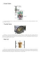
FDA Series High Performance Control & Choke Valves Like all Cyclonic valves, the FDA Series is built with the Cyclonic Design Difference. When you need to control a wide range of pressures and flow rates of gases or liquids, Cyclonic’s superior design gives you accurate control and a long safe valve life. Easy Actuation Changes Pre-drilled for simple in-line actuation changes, whether manual or automated.
Field Lubricated Stem Can be used with handle or actuator.
Upstream Driver Allows for easy service of internal components.
Low Torque Exclusive internal gear drive requires less torque, often allowing use of smaller, less expensive actuation. Precise repeatable control.
In-Line Flow Path Minimizes pressure drop, erosion and cavitation.
Short Pattern Design Greater flexibility where space is limited. 100% Testing Each valve we make is tested to ANSI B16.34 / API 598 standards.
Tungsten Carbide Control discs and extended downstream erosion protection.
FDA Series Technical Specifications • Machined from solid bar stock; no porosity, limitless possible lengths • Pressure ratings up to 10,000 psi MOP • XylanTM coated 17-4 stainless steel stem and disc driver • Standard materials of API 75K 4130 and 316SS, or customer-specified materials • ANSI B16.34 and/or API 6A wall thickness and bolt loading • Manual, electric, hydraulic or pneumatic actuation • Open/close or modulating service • Selectable failure position • Raised Face and RTJ flanges available
In order to consistently offer you the highest quality, fully engineered products, we reserve the right to change our specifications and designs at any time. Cyclonic Valve products and the Cyclonic logo are registered and/or common law trademarks of Cyclonic Valve Company, Inc. This document, including textual matter and illustrations, is copyright protected by Cyclonic Valve Company, Inc., with all rights reserved ©2011 Cyclonic Valve Company.
Cyclonic valves are more than just valves. They’re SOLUTIONS!
Cyclonic Valve Headquarters in Tulsa, OK Since 1991, Cyclonic has been setting the standards for precise and repeatable control of gases and liquids. We listen to our customers, and then design and manufacture valves to meet and exceed their expectations. HOW DO WE DO THAT? Cyclonic’s in-house manufacturing capability means superior quality control, unmatched customer service, and shorter lead times. Our valves are machined from solid bar stock, in API 75K 4130 or 316 stainless steel. Cyclonic’s tungsten carbide wear components and proprietary designs provide Class VI shutoff, low torque operation, and accurate flow control. Our exclusive “Side Entry” design allows simple one-man complete in-line inspection and maintenance, critical for increasing safety and protecting the environment. Our “EDS Erosion Detection System” can prevent fluids or gases from escaping into the environment by providing early warning before an incident happens. TM
WHO USES CYCLONIC VALVES? • Anadarko • Devon • BP • Marathon Oil • Baker Hughes/Centrilift • Newfield • Chesapeake • QEP • Chevron • Quicksilver • ConocoPhillips • Schlumberger/Reda • Denbury • Many others HOW ARE THEY USED? Cyclonic valves are used for automated and manual production chokes, plunger lift control, high pressure control of CO2, water, and steam injection, as by-pass valves, blow-off/bleed-down valves, at OEM pump testing and repair facilities, as compressor suction/by-pass/discharge valves, and in many other applications. Most common line sizes 1” - 6” are readily available, in pressure ratings up to 10,000 psi. End connections include API and ANSI flanges, NPT, BW, SW, Victaulic®, wafer style or other customer specified connections. It all comes down to this... The Cyclonic difference Exceeding your expectations every day.
All Cyclonic Valves are proudly made in the USA.
Imagine the possibilities... Cyclonic Valve Company, Inc. 2349 West Vancouver Broken Arrow, OK 74012-1183 918-317-8200 or 1-800-922-1707 FAX 918-317-8206 EMAIL [email protected]
FDA 2/12
1.125-12 UNF-2A 1.49 (ABF)
(FDA4006-D9S)
4" CL 600, D9 Discs, RF API 75K , TC Lined WS HNBR/Nitrile Seals
2349 W. Vancouver Broken Arrow, OK 74012 www.cyclonic.com 1-800-922-1707
A
10.73
Notes:
22
1. Control discs available for up to 110 Cv, with area equivalent to 120/64” orifice.
20
4
1
23
21
2
7
6
5
20
2. Recommended spare parts are: Control 02 Discs (items 12), Rebuild kit CRK-FA4xx-QP-RL-6S, Wearsleeve assembly WSXA0118-011N2 (items 8-11). Optional spare parts include Stem (item 4) and DiscDriver™ (item 13). Spare parts price list is available on request.
B
B
C
C
3. Actuation options include: handle with position indicator plate, electric or pneumatic actuators. Manual valve is furnished with provisions for future actuator mounting (requires mounting kit).
4x
3
4x .375-16 UNC-2B .560 (S103) 2.500
1.248 .743+-.000 .005 Stem Flats (DL34)
Body
4. Material and finishes are appropriate for intended service. Specifications are available on request. 5. All nominal dimensions shown are for reference. Tolerances comply with applicable industry standards.
6x 16
19
14
18
17
15
13
12
11
10
9
3
WS
6x
SECTION B-B
3
DRV
SECTION C-C
SECTION A-A 02
ITEM
PART NUMBER
DESCRIPTION
QTY.
ITEM
PART NUMBER
DESCRIPTION
QTY.
ITEM
PART NUMBER
DESCRIPTION
QTY.
1 2 3 4 5 6 7 8
CBD0047A-9C200 SLB1406-DUS01 DPN2501-44700 CST00092-48129 TW164125-27086 PPK1252-V3100 MBU1252-PM100 WS000118-01109
Body, Control Valve Sleeve Bearing Dowel Pin, 1/4" Dia. x 1/2" Stem, Control Valve Thrustwasher Seal, PolyPak Backup Ring Wearsleeve
1 1 16 1 1 1 1 1
9 10 11 12 13 14 15 16
DSL00034-50100 OR20152-V3100 OR20148-V3100 D9S2XXXX-XXXXX DRV00048-48129 CE000012-27100 TW445363-27055 CVR00018-9C104
Discharge Sleeve O-Ring O-Ring Disc, Control Driver Sleeve Thrustwasher Retainer, Control Valve
1 1 1 2 1 1 1 1
17 18 19 20 21 22 23
OR20248-V3100 BU80248-V2100 OR20161-V3100 FHH1409-B7H04 GZ00428-57213 FSS0428-44200 PPG250H-44100
O-Ring Backup Ring O-Ring Bolt-HH,.875"-9 x 3.250" Grease Zerk Set Screw, .250"-28 x .250" Plug, 1/4" NPT
2 1 1 16 1 1 1
02
02
02 DRAWN APPR.
NAME
DATE
MJM .
10/2/13
DO NOT SCALE DRAWING
Approximate Weight: 140 Lbs. Doc. No.
PROPRIETARY AND CONFIDENTIAL
By hherring at 1:45 pm, Sep 20, 2019
THE INFORMATION CONTAINED IN THIS DRAWING IS THE SOLE PROPERTY OF CYCLONIC VALVE COMPANY, INC. ANY REPRODUCTION IN PART OR AS A WHOLE WITHOUT THE WRITTEN PERMISSION OF CYCLONIC VALVE COMPANY, INC IS PROHIBITED.
02 - CBD0047A-9C100 was -09100, CVR00018-9C100 was -09100, GZ00428-57213 was GZ0042857x13, CRK-FA4xx-QP-RL-6, was CRK-FA406-QP-RL-6, Removed TW3540P-27032 -DLJ 09/20/2019
A
5.56±.06
FA406-xxP-4-4ZZ
1.19 (Flats)
REV
CD-FDA4006-D9SP-9-4-5-RL-6S 02 S:\SWData\Assemblies\
SHEET 1 OF 1
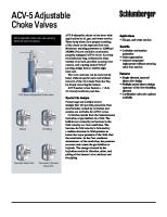
Back-up Power Powered Electric Actuators
MSB, ADC and ESR Series
ESR & ADC-Series Enclosures ALL DIMENSIONS IN INCHES �������������������������� ������������������������� �����������
�����������
���������� ����� �����������
���������� �������������
��� ��� ��� ���
���
����������
���
����
��� ���
���
��������
��� ���
���
���������������� ���������������������
���
MSB & LADC-Series Enclosures ALL DIMENSIONS IN INCHES �������������������������� �������������������������� �������������� ���������� ���������������
������������� ����������� ���������������
����
Optional Mechanical Stop
���
���������������������������������
���
������
����� ����������
������
�����
��� ����
���
������������ �����������
���
��� �����°
���� ����
��������
��� ��� ���
��� ���������������� �����������������
Introduction
Rugged Electric Actuators with Internal Back-up Power for Valves and Dampers Valvcon: A Tradition of Innovation
Features at a Glance!
Valvcon is the leader in the design and manufacture of compact, reliable, electronically controlled electric actuators for valves and dampers. Valvcon offers a complete line of electric actuators for accurate positioning of dampers and valves in the aerospace, automotive, consumer services, discrete manufacturing, energy, environmental, oil/pipeline, petrochemical, power/utilities, process, recreation, transportation, and water/wastewater industries.
MSB Series
Valvcon has developed and introduced the industry’s most innovative products, including simple “set and go” calibration, intelligent processor-based digital electronics, “Plug-in” accessory boards, “Fail-Safe” actuators, as well as electric actuators designed for remote control, solar-powered applications. Valvcon has built its reputation and success on the ability to envision, implement, and deliver innovative actuator technology products and services to support emerging market requirements. As emerging technologies and market needs continue to evolve, Valvcon will lead the way with high quality actuators that exceed industry expectations and further refine the valve actuation process.
Actuators from Valvcon Under the industry term “Fail-Safe,” Valvcon offers several product lines that are designed to drive a valve or damper to a pre-determined position in the event of a power loss. Under normal power conditions, they provide accurate positioning in response to the powered control signals. Mechanical Spring Back-up — Valvcon’s MSB Series provides an internal mechanical spring for back-up power. Under normal conditions, the actuator is driven by an internal motor. When power is lost, the mechanical spring immediately drives the valve or damper to a pre-set position. Internal Battery Power — Valvcon’s ADC Series provides an internal battery pack. Like the MSB series, the actuator is driven by an internal motor under normal conditions. When power is lost, the internal battery pack comes alive, and can either immediately drive to the pre-set position, or continue to respond to a maintained control signal. The ADC Series is an excellent choice for modulating applications, or any application where a less expensive solution is desired. Electronic Spring Return — Valvcon’s ESR Series provides an internal bank of supercapacitor power storage devices that never need replacement. Designed for two position operation, it provides true two-wire control: when the actuator is energized, it drives to one position; when de-energized, the actuator powers itself to the other position. The ESR Series is appropriate for applications that require operation from a single pair of wires.
• The mechanical spring is integral to the housing. It is wound during initial powerup, and remains in “stand-by” mode until a power outage. This means no increase in size and little increase in weight compared to a standard actuator. • The enclosure measures only 9.5” x 10.5” x 11.5” and weighs only 36-39 pounds. • Special low current draw DC powered models are ideal for remote, solarpowered sites such as well heads and pipelines. • No periodic or preventive maintenance required. ADC Series • Internal battery packs allow for continued modulation during power outages, provided the control signal remains. • Field-settable for “fail clockwise” or “fail counter-clockwise.” ESR Series • Operates like a solenoid valve — energize two wires to drive in one direction, then de-energize to allow the stored energy to drive it in the other direction. • Super-capacitors have a useful life of 8-10 years without replacement of the energy storage devices. Valvcon Back-up Powered Actuators: • Patented technology provides back-up capabilities within the standard size actuator enclosures! • Dual conduit openings make wiring easier, and keep power and control wiring separate. • Two year warranty.
1
MSB Specifications
Motor
Mechanical Spring Back-up Power
With Valvcon’s patented technology, the spring is wound once — without the need to wind the spring on each cycle, Valvcon’s MSB series uses standard, compact, highly efficient motors and drive trains. Upon initial power-up, the actuator automatically winds the internal power spring. When fully wound, the spring is latched in stand-by mode and the actuator operates as a normal actuator. A power interruption will cause the spring to unlatch, driving the actuator output to the pre-determined “power loss” position. This position can be fully clockwise or fully counter-clockwise. When power is returned to the actuator, the spring wind cycle is repeated.
de
Sp r in gW
Mo
ind
Mo
n Ru
de
Available for both AC and DC applications, MSB Series actuators require little constant power and can be an excellent choice for solar, remote applications. External “ready” indicator signal is available for control panel use. Speed control options provide a choice for fast close or slow close upon loss of power.
DC Slave Motor
Power Loss
Spring
Output
The above diagram illustrates the three operational modes of the actuator: Spring Wind, Run, and Power Loss. The DC slave motor sets the mode. In Spring Wind Mode, input power is used to wind the spring. In Run Mode, input power is used to drive the actuator’s output. During power loss, power from the internal spring is used to drive the actuator’s output.
Temperature Range
-40° F to 150° F. At temperatures below 32° F, Heater Thermostat is required.
Conduit Connections
(2) 3/4” NPT
Output
ISO 5211 F07 and F10 bolt circles, with 1” female square. Optional metric output: 22mm square by 30mm deep
Duty Cycle
AC applications: The actuator may run continuously at ambient temperatures at or below 104°F for up to 15 minutes. After running for 15 minutes, the actuator may operate at up to 75% duty cycle (that is, between each 90 degree rotation, the actuator must rest for 1/3 of the 90 degree cycle time) NOTE: AC Applications: At 50Hz, the duty cycle is 60% @ 104° F DC Applications: Continuous
Voltage
115VAC: 103.5 to 126.5VAC, 50 or 60 Hz 230VAC: 207 to 253VAC, 50 or 60 Hz 12VDC: 10.8 to 13.2 VDC 24VDC: 22.6 to 26.4 VDC
Limit Switches
(2) Single pole, double throw switches rated for 1/3 HP, 10 amps @ 125/230VAC, CSA certified. The two standard switches are used for end of travel control, and may also be used for pilot or position indication applications in on/off or jogging applications
Motor
AC Applications: Split phase capacitor driven motor with Class B or better insulation; sub-fractional horsepower motor DC applications: Brushed, DC, sub-fractional horsepower
Lubrication
Permanently lubricated gear train and bearings
Gear Train
Hardened steel spur gears
Approximate Weight
36 lbs. (600 inch lb. models)
Enclosure
Cast aluminum
Springs
Stainless steel, reverse wound, flat coil springs
Spring Returns
500 90° rotations (after 500, contact factory for servicing information)
Rewind time (after 90° rotation)
90 secs. ( 600 inch lb. models)
Power Loss Position
Factory set, fully clockwise or fully counter-clockwise
Degrees of rotation
15 to 90 degrees
37.5 lbs. (1200 inch lb. models)
150 secs. (1200 inch lb. models)
39 lbs. (1800 inch lb. models)
210 secs. (1800 inch lb. models)
Technical Data Torque (in lbs)
Normal Operating Speed (per 90° rotation, in seconds) 115VAC or 230VAC
12VDC or 24VDC
Power Loss Speed (90° rotation)
Power Loss Speed With Speed Control Option
Normal Operating Current (in amps)
115VAC 230VAC 12VDC 24VDC
115VAC 230VAC
12VDC
24VDC
Duty Cycle*
115VAC or 230VAC
12VDC or 24VDC
600
17
12