![EMS2 Installation ManualD16 - US [PDF]](https://pdfs.asia/img/200x200/ems2-installation-manuald16-us.jpg)
7 0 4 MB
Installation Industrial Engines EMS 2
I 1(1)
TAD1640GE, TAD1641GE, TAD1642GE, TWD1643GE, TAD1641VE TAD1642VE, TAD1643VE, TAD1650VE,TAD1650GE,TAD1651GE TWD1652GE, TWD1653GE, TAD1660VE, TAD1661VE, TAD1662VE TAD1640VE-B, TAD1641VE-B, TAD1642VE-B
Content Safety Information ...................................................................................... 2 Installation Tools and Documentation ...................................................... 4 Special Tools ............................................................................................ 4 System Information .................................................................................... 5 EMS ........................................................................................................... 5 Control System Installation ..................................................................... 50 Connection ............................................................................................. 50 Calibration and Settings ........................................................................... 71 Parameter Setting .................................................................................. 71 Diagnostic Function ............................................................................... 92 Fault Code Register ............................................................................... 95 Alphabetical index .................................................................................. 109
47701683 10-2012 © AB VOLVO PENTA
1
Safety Information Presentation
Working methods
This installation manual contains information for installing and carrying out function and performance checks on the EMS 2 system (electronic control of the injection system). This instruction manual is intended only for professional use. Read the instructions carefully before starting the installation. If the installation is performed in an incorrect manner, it may cause personal injury or damage to property and machinery. Ask your Volvo Penta dealer for help if there is anything in this manual that you do not understand or are uncertain about.
The work must be performed by a Volvo Penta workshop or other authorized, well-equipped workshop by qualified and experienced personnel. These instructions refer to such personnel as fitters. This installation manual is intended to be used together with the operator's manual for the engine concerned. The fitter is responsible for ensuring that the system functions in accordance with these installation instructions. Volvo Penta disclaims all responsibility for injury to persons or damage to property that may occur as a result of not following the installation guidelines, or for work carried out by unqualified personnel.
! This symbol is used in the manual and on the product to call attention to the fact that this is safety information. Always read such information very carefully. Safety texts in the installation manual have the following order of priority:
DANGER! Indicates a hazardous situation which, if not avoided, will result in death or serious injury.
WARNING! Indicates a hazardous situation which, if not avoided, could result in death or serious personal injury.
CAUTION! Indicates a hazardous situation which, if not avoided, could result in minor or moderate personal injury. IMPORTANT! Indicates a situation which, if not avoided, could result in property damage. NOTICE! Used to draw attention to important information that will facilitate work or operations. This symbol is used on our products in certain cases and it refers to important information in the operator's manual. Make sure that warning and information symbols on the engine are clearly visible and legible. Replace symbols that have been damaged or painted over.
2
47701683 10-2012 © AB VOLVO PENTA
Safety Information Set out below is a summary of the risks and safety measures that must be observed or carried out when the EVC system is installed and calibrated.
! Disconnect connectors to the EMS control unit before any arc welding is carried out. Turn the current off at the main switches. Undo and remove the control unit connectors. Reconnect the EMS 2 control unit connectors once welding is completed and the welding equipment has been removed.
! Take care to keep clear of the engine's moving parts during functional checks and operations. There is a risk for personal injury when approaching a running engine. Remember that loose clothing and long hair can fasten in rotating parts and cause serious injury.
! Never work on an engine that is suspended from lifting gear (a crane or similar).
! The engine must not be run in areas where there are explosive materials or gases.
! Only start the engine in well-ventilated places. If the engine is operated in an enclosed space, make sure that there is sufficient ventilation to remove the exhaust gases and crankcase fumes from the workplace.
47701683 10-2012 © AB VOLVO PENTA
! Never expose battery compartments to open flames or electrical sparks. Never smoke in the vicinity of the batteries. Batteries generate hydrogen gas during charging, which can combine with air to form an explosive mixture. This gas is highly flammable and explosive. Incorrect connection of the batteries may cause sparks that in turn cause an explosion resulting in damage. Do not switch battery connections when attempting to start the engine (risk for sparks) and do not lean over the batteries. Refer to the instructions in the engine operator's manual.
! Make sure that the positive (+) and negative (-) battery cables are correctly connected to the corresponding battery terminals. Serious damage may be caused to the electrical equipment if the cables are transposed. Refer to the wiring diagram in the engine operator's manual.
! Always wear eye protection when charging or handling the batteries. Battery electrolyte contains sulfuric acid which is highly corrosive. If electrolyte comes into contact with bare skin, wash the exposed area immediately with copious amounts of clean water and soap. Then seek medical attention. If you get battery electrolyte in your eyes, flush them immediately (preferably using eye wash equipment) with copious amounts of clean water. Then seek immediate medical attention.
3
Installation Tools and Documentation, Special Tools
Installation Tools and Documentation Special Tools
p0005125
3838619 VODIA, diagnostic tool VODIA, complete with cable harness Refer to the VODIA operators manual when ordering separate parts.
88890074 Multimeter Multimeter
Other Special Equipment Other special equipment The tools below are used for work on the engine wire harness. The tools are not part of the Volvo Penta range, and must be ordered from AMP or Deutsch dealers. Contact Volvo Penta Quality Action Center if you have trouble finding a dealer. AMP connector: 42-pin CIU, 62-pin EMS, 2 and 3 pin Bosch etc.
P0003809
P0003813
HDT-48–00 Press tool
P0003810
AMP 726 519 Removal tool, 2.8 mm pin width
P0003811
AMP 825 514 Press tool For 4.8 and 6.3 cable shoes. Flat-pin connectors.
4
AMP 539 968 Removal tool, 1.5 mm pin width
AMP 726 519 Removal tool, 0,06 inch pin width
P0003811
P0003813
AMP 929 039 Removal tool, 2.8 mm pin width
AMP 238 635 Press tool
P0003814
GHW 50000 017 586 Removal tool, 2.8 mm pin width For GHW connector (relay box)
47701683 10-2012 © AB VOLVO PENTA
System Information, EMS
System Information EMS Engine control system EMS 2 stands for “Engine Management System” and is an electronic system with CAN communications (Controller Area Network) for control of diesel engines. The system has been developed by Volvo Penta and includes fuel control and diagnosis function. The system consists of a control module, six unit injectors, a number of sensors that supply the control module with measurements, sockets for diagnosis and functional checks. The engine can be connected to a communication interface comprising a CAN-link and a serial link.
CAN (Controller Area Network) The CAN J1939 link handles all communication between the engine control module EMS 2 and the CIU, in addition to the diagnostics that are handled by the so called J1708/J1587 link. The CAN link is much faster than the J1708/J1587 link. The CAN link has been prepared to connect to other components with SAE J1939 protocol such as instrument panels and transmissions. If, for some reason, a fault develops on the CAN link, signals for the rpm-potentiometer and the start and stop knobs are taken over by the J1708/J1587 link. However, instrument and indicator lamps are completely turned off. If a fault occurs on both links, GE engines maintain engine speed, while VE engines go to idle. The only way to shut off the engine in this case is to use the auxiliary stop (AUX-STOP) placed on the engine’s left side.
47701683 10-2012 © AB VOLVO PENTA
5
System Information, EMS
CIU (Control Interface Unit) The CIU is a “translator” between the CAN bus and the customer’s own control panel. This unit has two serial communication links, one fast and one slow. The fast one is a CAN link that features a bus speed of 250 Kbit/ s. All data regarding instruments, indicator lamps, contacts and potentiometers are controlled by this bus. The slower J1708/J1587 link handles diagnostic information for, among other things, the flashing code. The diagnosis tool VODIA also uses the J1708/J1587 link to communicate with the system. P0002060
6
47701683 10-2012 © AB VOLVO PENTA
System Information, EMS
Fuel control The engine’s fuel requirement is analyzed up to 100 times per second (depending on engine rpm). The engine’s injection amount and injection timing is controlled electronically via fuel valves on the unit injectors. This means that the engine always receives the correct volume of fuel in all operating conditions, which offers lower fuel consumption, minimal exhaust emissions etc. The control module checks and controls the unit injectors so that the correct amount of fuel is injected into each cylinder. It calculates and sets the injection angle. The control is primarily performed using the speed sensors and the combined sensor for boost pressure/charge air temperature. The control module affects the unit injectors via an electronic signal to the unit injectors’ electromagnetic fuel valve, which can open and close. When the fuel valve is open, fuel flows through the unit injector hole and out through the fuel channel. Fuel is not sprayed into the cylinder in this position. When the fuel valve closes, pressure starts to build from the unit injector’s mechanically operated pump plunger. When sufficient pressure has developed, fuel is injected into the cylinder via the unit injector’s injector section. The fuel valve is re-opened and pressure in the unit injector decreases at the same time as the fuel injection to the cylinder stops. In order to determine when the fuel valve shall open or close, the control module has access to signals from sensors and switch contacts.
Altitude correction The control unit is fitted with an atmospheric air pressure sensor and an altitude correction function for engines operating at high altitudes. This function limits the fuel volume in relation to ambient air pressure. This is to prevent smoke, high exhaust temperature and to protect the turbocharger from over-speeding. Diagnosis function The task of the diagnosis function is to detect and locate disturbances within the EMS 2 system, to protect the engine, and to provide information about problems that have developed. If a malfunction is discovered, this is announced by warning lamps, a flashing diagnostic lamp or in plain language on the instrument panel, depending on the equipment used. If a fault code is obtained as a flashing code or in plain language, this is used for guidance in any troubleshooting. Fault codes can also be read by Volvo’s VODIA tool at authorized Volvo Penta workshops. In case of serious malfunctions, the engine is shut down completely, or the control unit reduces the power output (depending on application). A fault code is set as a guide when fault tracing.
Calculating fuel quantity The amount of fuel that is sprayed into a cylinder is calculated by the control module. The calculation determines the time that the fuel valve is closed (when the fuel valve is closed fuel is sprayed into the cylinder). The parameters controlling injected amount of fuel are: •
Requested engine speed
•
Motor protector
•
Temperature
•
Boost air pressure
47701683 10-2012 © AB VOLVO PENTA
7
System Information, EMS
In- and out signals Information from the sensors provides exact reports regarding operational circumstances and makes it possible for the control unit processor to calculate the correct injection amount, injecton timing and engine condition, among many other things.
Input signals The control unit receives input signals regarding engine operational conditions along with information from the following components: - Coolant temperature sensor - Charge air pressure / charge air temperature sensors - Crankcase pressure sensor - Position sensor - Camshaft - Engine speed sensor - Flywheel - Cylinder cooling pressure sensor - Coolant level sensor - Oil pressure sensor - Oil level and oil temperature sensors - Fuel pressure sensor - Water in fuel sensor - Air filter pressure sensor - Air temperature sensor - Exhaust temperature sensor (TWD1643GE)
8
47701683 10-2012 © AB VOLVO PENTA
System Information, EMS
Output signals The control unit uses the input signals to control the following components: - Unit injectors - Starter motor - Alternator - Main relay - Pre-heat relay - Wastegate (TWD1643GE, TAD1650VE) - Cold start valve (TWD1643GE) - Valve mechanism, internal EGR (TAD1650VE) - Electronic fan control
47701683 10-2012 © AB VOLVO PENTA
9
System Information, EMS
Instruments DCU (Display Control Unit) DCU is a digital instrument panel that communicates with the engine control unit via the CAN-link. DCU has several functions, such as: Engine control - Start, stop, rpm regulation, preheating, etc.
P0002932
Monitoring - Shows engine speed, charge pressure, charge temperature, coolant temperature, oil pressure, oil temperature, engine hours, battery voltage, instantaneous fuel consumption and fuel consumption (trip fuel). Diagnostic - Shows fault codes in text. Lists previous faults. Parameter setting - Idle speed, alarm limits for oil temperature/coolant temperature, regulation mode (speed droop/ isochronous).
DU (Display Unit) DU is an instrument for showing the engines operating values. The values are shown graphically on an LCD display. The display communicates via the CAN link and consists of a computerized unit for attachment to the control panel. It is connected to the CAN link between the engine control unit and CIU or DCU.
P0002061
10
47701683 10-2012 © AB VOLVO PENTA
System Information, EMS
Electrical interface General This document describes how the Volvo Penta industrial engines equipped with the control systems EMS and EMS2 may be controlled. There are a number of interfaces available to control the engine. The interfaces are:
• Bus interface • CIU • DCU The common thing about the three first interfaces is that the engine is controlled over two serial communication buses. The CIU and DCU uses the bus interface to communicate with the engine. IMPORTANT! If non Volvo Penta equipment is connected to the communication busses there is always a risk that the safety of the system is jeopardized.
47701683 10-2012 © AB VOLVO PENTA
11
System Information, EMS
Abbrevations BAM Broadcast Announce Message CAN Controller Area Network DEF Diesel Emission Fluid EATS Engine After Treatment System EIC Engine Interface Connector EECU Engine Electronic Control Unit EMS Engine Management System EMS 2 EMS used on TAD734GE, D9, TAD125xVE, D13 and D16 engines FMI Failure Mode Identifier OEM Original Equipment Manufacturer SPN Suspect Parameter Number VP Volvo Penta Relevant dokumentation
• 7748665
Electrical interface specification industrial engines EMS and EMS2
• SAE J1939-73 • SAE J1939-71
12
47701683 10-2012 © AB VOLVO PENTA
System Information, EMS
Engine control interface Volvo Penta industrial engines can be controlled in three different ways. Via bus interface, CIU or DCU. The bus interface is used by those who makes there own control system that and wants to control the engine over SAE J1939 and J1587. Volvo Penta provided two different systems to control the engines, CIU that provides a number of digital/analogue outputs to control the engine. And DCU that has all buttons included in the unit but still provides some digital/ analogue inputs and outputs. CIU This is the interface for those who wants to make there control panel or non bus based control unit. DCU This is the interface for those who wants a complete unit that is ready to run the engine without make any button. But the possibility to make some customization is still here. The DCU is equipped with a display that shows engine data and diagnostics translated to text.
Electrical interface Bus interface 8-pole deutsch connector recepticle. Pin 1 2 3 4 5 6 7 8
47701683 10-2012 © AB VOLVO PENTA
Description CAN H CAN L Battery – Battery + Ignition and stop request if energized to run Stop request energized to stop J1587A J1587B
13
System Information, EMS CIU The electrical interface to the CIU is 42-pole AMP connector. Pin 1 2 3
Description Idle request Potentiometer ground Potentiometer signal
Pin 22 23 24
4 5 6 7
Not used Not used Not used
25 26 27 28
Preheat indication(1) Coolant level alarm Oil pressure alarm Battery + Ignition (key switch)
29 30 31 32 33 34 35 36
Governor mode request Potentiometer supply Not used Not used Tachometer Coolant temperature gauge Start request Diagnostic indication
Over speed indication(2) Buzzer (3) Easy link bus Coolant temperature alarm Battery alarm CAN L CAN H Gauge power supply Battery –
8 9 10 11 12 13 14 15 Frequency select(4) 16 Diagnostic switch 17 Preheat request(5) 18 19 20 21
Not used Engine protection override req. Oil temp gauge Oil pressure gauge
Description J1587A Not used
37 J1587B 38 Running indication(6) 39 Fuel alarm 40 Oil temperature alarm 41 Stop request 42 Not used There is a cable harness available with all wires connected that applies to the above table. All indicators shall be less than 3W. All switches are active when shorted to battery+.
1. Not for 124xGE 2. Genset only 3. Power pack only 4. Genset only 5. Not for 124xGE 6. Genset only
14
47701683 10-2012 © AB VOLVO PENTA
System Information, EMS DCU Connector 1, 8-pole deutsch connector. Pin Description 1 CAN H 2 3 4
CAN L Battery – Battery +
Pin Description 5 Ignition and stop request if energized to run 6 Stop request energized to stop 7 J1587A 8 J1587B Connector 2, 12-pole deutsch connector:
Pin 1 2 3 4 5 6
Description External stop External Start / Ignition LSS1 (Buzzer) Easylink gauge power Easylink Data Easylink Ground
Pin 7 8 9 10 11 12
Description Throttle + (10V) Throttle input Throttle – LSS2 (Running indication) LSS3 (spare) LSS4 (spare)
All indicators shall be less than 3W. All switches are active when shorted to battery +.
47701683 10-2012 © AB VOLVO PENTA
15
System Information, EMS
Power up sequence The system powers up when the ignition is switched on.
Start A start request is addressed by the start signal. The engine will then start to crank and it will continue to do so until one of the following conditions becomes true.
• The start signal goes inactive. • The engine speed exceeds a stated limit, typical about 480 rpm.
• The cranking time exceeds a stated limit, typical about 20 s. 30 s for genset engines.
Bus interface Associated message: J1939: Start request in VP Status J1587: Start request in PPID 98 CIU Associated hardware/input: Start request. DCU Associated hardware/input: Start request.
16
47701683 10-2012 © AB VOLVO PENTA
System Information, EMS
Power down sequence To perform a power down the following sequence shall be performed: 1 Switch off the ignition 2 Send a stop request to the system. 3 When the power down sequence is finished the engine will stop communicating. Auto shutdown will power down the system if the ignition is switched off. Different length of time sequences are being used. (Running engine will continue to run until a stop request is sent to the system). External stop External stop is placed in the 8-pole connector on pin 6. Energized to STOP / RUN Default external stop function is set to Energized to STOP. To use the stop function as Energized to STOP, apply EMS supply voltage on Pin 6 to stop the engine. By option or changing a parameter it can be set to Energized to RUN. To use the stop function as Energized to RUN, Pin 6 needs EMS supply voltage for the engine to start and run. To stop the engine EMS supply voltage needs to be removed from Pin 6. Energized to RUN on Pin5 If the function “energized to run” is used the extra stop is on pin 5 together with the ignition. The main power MUST NOT be switched off before the power down sequence is finished.
47701683 10-2012 © AB VOLVO PENTA
17
System Information, EMS Stop A stop request is addressed by the stop signal and will stop the engine. Bus interface Associated message: J1939: Stop request in VP Status J1587: Stop request in PPID 98 CIU Associated hardware/input: Stop request. DCU Associated hardware/input: Stop request.
18
47701683 10-2012 © AB VOLVO PENTA
System Information, EMS
Throttle (Synchronizing/Load sharing) Versatile The driver pedal demand is realized by the throttle request signal. The signal is interpreted as a 0-100% request where 0% means idle speed and 100% maximal engine speed. This demand will only be overridden if an error occur that may damage the engine or a request with the CAN-message TSC1. Genset This is used for controlling the engine speed in order to synchronize and to perform load sharing. 50% throttle corresponds to 1500 or 1800 rpm. Bus interface Associated message: J1939: Throttle in VP Status J1587: PPID 132 CIU Associated hardware/input: Potentiometer supply, signal and ground. DCU Associated hardware/input: Increase decrease engine speed buttons or potentiometer supply, signal and ground.
47701683 10-2012 © AB VOLVO PENTA
19
System Information, EMS
Torque speed control It is possible to override the throttle that is sent in VP Status. This is done with TSC1. When controlling the engine speed from the gearbox (SA = 0x03) it always have the highest priority. Bus interface Associated message: J1939: TSC1 J1587: N/A CIU Associated message: J1939: TSC1 J1587: N/A DCU Associated message: J1939: TSC1 J1587: N/A
20
47701683 10-2012 © AB VOLVO PENTA
System Information, EMS
Governor mode The engine is normally running in isochronal mode. If there is a need for a smoother controller this can be realized by an active droop mode signal. When the governor mode signal is active then droop functionality is added to the engine speed controller. Bus interface Associated message: J1939: Governor mode in VP Status J1587: N/A CIU Associated hardware/input: Governor mode request. DCU Associated hardware/input: Available in the menu.
47701683 10-2012 © AB VOLVO PENTA
21
System Information, EMS
Idle switch Versatile If the throttle request is malfunctioning (meaning that there is an electrical fault on the potentiometer or the cable harness) then the idle switch can be used for limp home driving. If there is a fault on the pedal signal then the engine will go to idle speed. If then the idle switch first goes active (meaning that the driver has released the pedal) and then goes inactive (meaning that the driver is pressing the pedal down) then the engine will slowly ramping up the engine speed. The engine speed will be ramped up to maximal 80 % of normal maximal engine speed. When releasing the pedal the engine will immediately go down to idle speed. Genset If an idle request is sent to the engine it will go to idle speed if the engine unloaded. Bus interface Associated message: J1939: Idle request in VP Status J1587: N/A 2.11.2 CIU Associated hardware/input: Idle request. CIU Associated hardware/input: Idle request. DCU Available in the menu
22
47701683 10-2012 © AB VOLVO PENTA
System Information, EMS
Preheat This function is not valid for 124xGE. When a preheat request is received the engine will activate the preheat device if the following conditions are fulfilled.
• The coolant temperature is low. • The engine is not running. The preheat device will be activated for a time dependent on the coolant temperature. The engine will also decide, using the coolant temperature, if after heating should be used. Preheating will be terminated immediately if the driver starts cranking. It is possible for the costumer, using Volvo Penta Parameter setting tool, to choose if preheating should be activated immediately after turning on the ignition (prior to same conditions as above). Bus interface Associated message: J1939: Preheat request in VP Status J1587: N/A CIU Associated hardware/input: Preheat request. DCU Associated hardware/input: Available in the menu.
47701683 10-2012 © AB VOLVO PENTA
23
System Information, EMS
Frequency select This function is only valid for genset applications. The frequency switch is used for changing the nominal engine speed (i.e. switching between 1500 and 1800 rpm). For safety reasons the frequency can only be changed when the engine is stopped. EMS2 systems To make a system reset request stop wait 2 second after the last stop request. Then change the state of frequency select to the desired engine speed. Then send a stop request within 10 seconds after the first stop. The frequency select signal must change value during the frequency change. I.e. if the engine runs at secondary speed and the frequency select signal requests primary engine speed when the first stop is issued, the signal has to be switched to secondary followed by primary engine speed, before the second stop request is issued. It is possible to change the frequency using the Volvo Penta aftermarket tool. Bus interface Associated message: J1939: Frequency select in VP Status and & diagnostic request in VP Status. J1587: N/A CIU Associated hardware/input: Frequency select. DCU Associated hardware/input: Available in the menu.
24
47701683 10-2012 © AB VOLVO PENTA
System Information, EMS
Engine protection override It is possible to request engine protection override. When such a request is received the engine will deactivate the engine protection for a predefined time. Genset engines The engine protection is disabled as long as the request is active and for another 10s. Mobile / Versatile / Powerpack The engine protection is disabled as long as the request is active and for another 10s, but is maximized to 60 seconds. Bus interface Associated message: J1939: Engine protection override request in VP Status J1587: N/A CIU Associated hardware/input: Engine protection override request. DCU N/A
47701683 10-2012 © AB VOLVO PENTA
25
System Information, EMS
Communication J1939 Communication Description of supported frames, signals and messages. J1939 The following frames are supported by the EMS. See following pages. Tx = transmit, Rx = receive Identifier
Signal name
164xVE 1640-42GE 1643GE 165xVE 166xVE
18E8FF00 Ack
Tx
Tx
Tx
Tx
Tx
18EEFF00 Address Claimed
Tx
Tx
Tx
Tx
Tx
18ECFF00 BAM
Tx
Tx
Tx
Tx
Tx
18FECA00 DM1
Tx
Tx
Tx
Tx
Tx
18FECB00 DM2
Tx
Tx
Tx
Tx
Tx
18EBFF00 TP.DT
Tx
Tx
Tx
Tx
Tx
Drivers Demand Engine, Torque %
Tx
Tx
Tx
Tx
Tx
Actual Engine, Torque %
Tx
Tx
Tx
Tx
Tx
Engine Speed
Tx
Tx
Tx
Tx
Tx
Accelerator Pedal Pos. 1
Tx
Tx
Tx
Tx
Tx
% Load at Current Speed
Tx
Tx
Tx
Tx
Tx
Tx
Tx
Tx
Tx
0CF00400 Electronic Engine Controller 1
0CF00300 Electronic Engine Controller 2
18FEDF00 Electronic Engine Controller 3 Nominal friction, torque % 0000FEE3 Engine Configuration Engine Reference Torque 18FEEF00 Engine Fluid Level/Pressure 1 Fuel Delivery Pressure
Tx
Tx
Tx
Tx
Tx
Engine Oil Pressure
Tx
Tx
Tx
Tx
Tx
Tx
Tx
Tx
Tx
Tx
Tx
Tx
Tx
Tx
Tx
Engine Coolant Temperature
Tx
Tx
Tx
Tx
Tx
Engine Oil Temperature 1
Tx
Tx
Tx
Tx
Tx
Tx
Tx
Tx
Tx
Tx
Trip Fuel
Tx
Tx
Tx
Tx
Tx
Total Fuel Used
Tx
Tx
Tx
Tx
Tx
Boost Pressure
Tx
Tx
Tx
Tx
Tx
Intake Manifold 1 Temperature
Tx
Tx
Tx
Tx
Coolant Pressure Coolant Level 18FEE500 Engine Hours Total Engine Hours 18FEEE00 Engine Temperature 1
18FEF200 Liquid Fuel Economy Fuel Rate 18FEE900 Fuel Consumption, Liquid
18FEF600 Inlet/Exhaust Conditions 1
Air Inlet Pressure
26
Tx
47701683 10-2012 © AB VOLVO PENTA
System Information, EMS Identifier
Signal name
164xVE 1640-42GE 1643GE 165xVE 166xVE
Air Filter 1 Differential Pressure
Tx
Exhaust Gas Temperature
Tx
18EA0003 Request PGN 18EA0011 18EA00EA
Rx Rx -
Rx Rx Rx
Rx Rx Rx
Rx Rx
Rx Rx
Override Control Mode
Rx -
Rx -
Rx Rx -
Rx Rx Rx
Rx Rx Rx
Requested Speed Control Conditions
Rx -
Rx -
Rx Rx -
Rx Rx Rx
Rx Rx Rx
Override Control Mode Priority
Rx -
Rx -
Rx Rx -
Rx Rx Rx
Rx Rx Rx
Requested Speed/Speed Limit
Rx -
Rx -
Rx Rx -
Rx Rx Rx
Rx Rx Rx
Requested Torque/Torque Limit
Rx -
Rx -
Rx Rx -
Rx Rx Rx
Rx Rx Rx
Tx
Tx
Tx
Tx
Tx
Idle engine speed Start position: 1 Length: 2 bytes Resolution: 0.125 rpm/bit
Tx
Tx
Tx
Tx
Tx
Maximum engine speed Start position: 3 Length: 2 Resolution: 0.125 rpm/bit
Tx
Tx
Tx
Tx
0C000003 Torque/Speed Control 1 0C000011 0C0000E6
18FEF700 Vehicle Electrical Power Battery Potential (Voltage), Switched 0CFF4E00 VP Configuration (1000 ms)
0CFF4700 VP Engine industry (50 ms) Preheat indication Start position: 1.1 Length: 2 bits 0 = Inactive 1 = Active 2 = Error indication 3 = Not available
Tx
Tx
Tx
Tx
Tx
Running indication Start position: 1.3 Length: 2 bits 0 = Inactive 1 = Active 2 = Error indication 3 = Not available
Tx
Tx
Tx
Tx
Tx
47701683 10-2012 © AB VOLVO PENTA
27
System Information, EMS Identifier
Signal name
164xVE 1640-42GE 1643GE 165xVE 166xVE
Buzzer Start position: 3.1 Length: 2 bits 0 = Inactive 1 = Active 2 = Error indication 3 = Not available
Tx
Tx
Tx
Tx
Tx
Engine protection override ind. Start position: 3.7 Length: 2 bits 0 = Inactive 1 = Active 2 = Error indication 3 = Not available
Tx
Tx
Tx
Tx
Tx
General lamp test Start position: 4.1 Length: 2 bits 0 = Inactive 1 = Active 2 = Error indication 3 = Not available
Tx
Tx
Tx
Tx
Tx
Buzzer test/Lamp test Start position: 4.3 Length: 2 bits 0 = Inactive 1 = Active 2 = Error indication 3 = Not available
Tx
Tx
Tx
Tx
Tx
Start request Start position: 1.1 Length: 2 bits 0 = Inactive 1 = Active 2 = Error indication 3 = Not available
Rx
Rx
Rx
Rx
Rx
Stop request Start position: 1.3 Length: 2 bits 0 = Inactive 1 = Active 2 = Error indication 3 = Not available
Rx
Rx
Rx
Rx
Rx
Governor mode request Start position: 1.5 Length: 2 bits 0 = Inactive 1 = Active 2 = Error indication 3 = Not available
Rx
Rx
Rx
Rx
Rx
Idle speed select Start position: 1.7 Length: 2 bits 0 = Normal operation 1 = Idle speed request 2 = Error indication 3 = Not available
Rx
Rx
Rx
Rx
Rx
0CFF4611 VP Status (20 ms)
28
47701683 10-2012 © AB VOLVO PENTA
System Information, EMS Identifier
Signal name
164xVE 1640-42GE 1643GE 165xVE 166xVE
Frequency select Start position: 2.1 Length: 2 bits 0 = Primary engine speed 1 = Secondary engine speed 2 = Error indication 3 = Not available
NA
Rx
Rx
NA
NA
Preheat request Start position: 2.5 Length: 2 bits 0 = Inactive 1 = Active 2 = Error indication 3 = Not available
Rx
Rx
Rx
Rx
Rx
Engine protection override Start position: 2.7 Length: 2 bits 0 = Inactive 1 = Active 2 = Error indication 3 = Not available
Rx
Rx
Rx
Rx
Rx
Accelerator pedal position Start position: 3 Length: 2 bytes Resolution: 0.097752 (100/1023) %/bit 0xFEFF = error indication 0xFFFF = not available
Rx
Rx
Rx
Rx
Rx
Rx
Rx
Tx
Tx
Fuel disable request Start position: 5.1 Length: 2 bits 0 = Inactive 1 = Active 2 = Error indication 3 = Not available 18FEFF00 Water in Fuel Indicator - WFI Water in Fuel Indicator 18FE5600
Tx
Tx
Tx
AT1 SCR Reagent Tank 1 Information - AT1T1l AT1 SCR Tank Level (SPN 1761) Start position: 1.1 Length: 8 bits 0% = Empty Tank 100% = Full Tank
Tx
AT1 DEF Tank Low Level Indicator (SPN 5245) Start position: 5.6 Length: 3 bits 000: off 001: on - Solid 100: on - Fast blink (1Hz)
Tx
47701683 10-2012 © AB VOLVO PENTA
29
System Information, EMS Identifier
Signal name
164xVE 1640-42GE 1643GE 165xVE 166xVE
AT1 SCR Operator Inducement Severity Start position: 6.6 Length: 3 bits 000: No Inducement active 001: Inducement Severity 1 010: Inducement Severity 2 011: Inducement Severity 3 100: Inducement Severity 4 101: Inducement Severity 5
Tx
18FEE400 Shutdown (EPS) Engine Protection System has Shutdown Engine Start position: 5.1 Length: 2 bits 0 = Inactive 1 = Active 2 = Error indication 3 = Not available
Tx
Engine Protection System Approaching Shutdown Start position: 5.3 Length: 2 bits 0 = Inactive 1 = Active 2 = Error indication 3 = Not available
Tx
0CFEF500 Ambient Condition Ambient Air Temp
Tx
0CFD6E00 SCR1 Average Catalyst Reagent Consumption
Tx
Commanded Catalyst Reagent Consumption
Tx
NOTICE! The EMS does not support the address claim procedure and will always have source address 0x00. The EMS will however respond to an address claim request.
30
47701683 10-2012 © AB VOLVO PENTA
System Information, EMS
Location of Sensors Location of Sensors TAD1640GE, TAD1640VE-B, TAD1641GE, TAD1641VE, TAD1641VE-B, TAD1642GE, TAD1642VE, TAD1642VE-B, TAD1643VE
1
2 3
11 4
10 5
12
6
9 8 7
14
13
P0002058
1 2 3 4 5 6 7
Coolant level sensor, in expansion tank Charge air pressure and temperature sensor Air filter indicator Flywheel position and engine speed sensor Fuse Aux stop Oil pressure sensor
47701683 10-2012 © AB VOLVO PENTA
8 9 10 11 12 13 14
Water in fuel sensor Oil level and temperature sensor Fuel pressure sensor Crankhouse pressure sensor Coolant temperature sensor Piston cooling pressure sensor (not TAD1650/51GE) Camshaft position sensor
31
System Information, EMS
Location of Sensors TWD1643GE
1 2 3
4
10 5
6 9
7
8
11
15 12
14
13
P0002059
1 Coolant level sensor, in expansion tank 2 Charge air pressure and temperature sensor 3 Oil pressure sensor 4 Airfilter indicator 5 Aux stop 6 Fuse 7 “Water in fuel” sensor 8 Fuel pressure sensor
32
9 Oil level and temperature sensor 10 Crankhouse pressure sensor 11 12 13 14 15 16
Coolant temperature sensor Exhaust temperature sensor Piston cooling pressure sensor Flywheel position and engine speed sensor Camshaft position sensor Solenoid valve, drainage, water trap (optional), not shown in illustration
47701683 10-2012 © AB VOLVO PENTA
System Information, EMS
Location of Sensors TAD1650VE
1
2
3
9
4
10 7 8
5
66
12
11
P0005187
1 2 3 4 5 6
Crankhouse pressure sensor Charge air pressure and temperature sensor Flywheel position and engine speed sensor Fuse Aux stop Oil pressure sensor
47701683 10-2012 © AB VOLVO PENTA
7 8 9 10 11 12
Oil level and temperature sensor Water in fuel sensor Fuel pressure sensor Coolant temperature sensor Piston cooling pressure sensor Camshaft position sensor
33
System Information, EMS
Location of Sensors TAD1650GE, TAD1651GE
1 2 3 4 5 6 7
34
Coolant level sensor, in expansion tank Charge air temp and pressure sensor Air filter indicator Crank sensor (RPM) Fuse Aux stop Oil pressure sensor
8 9 10 11 12 13
Water in fuel sensor Oil level and temp sensor Fuel pressure sensor Crankhouse pressure sensor Coolant temperature sensor Camshaft position sensor
47701683 10-2012 © AB VOLVO PENTA
System Information, EMS
Location of Sensors TAD1660VE, TAD1661VE, TAD1662VE
2
1
3
4
11
5 10
6
7 9 12
8 13
14
P0014323
47701683 10-2012 © AB VOLVO PENTA
35
System Information, EMS
1 2 3 4 5 6 7 8
36
Coolant level sensor, in expansion tank Connection to SCR system Charge air pressure and temperature Air filter indicator Flywheel sensor, speed and position Fuses for SCR system Aux stop Water in fuel sensor
9 10 11 12 13 14
Oil level and temp sensor Fuel pressure sensor Crankhouse pressure sensor Fuel pressure sensor Camshaft position sensor Humidity sensor
47701683 10-2012 © AB VOLVO PENTA
BL/GN
BL/OR
P0004301
4 SB 1R
3
4
P2
1
30
2P
3
31
R 3
SB 1
2
P4
45 46
2 1
n
28 27
n
1
P2
6
5
10
SB
8
34
1234567
R/BL
26
CYL. 6
CYL. 5
CYL. 4
CYL. 3
CYL. 2
CYL. 1
9
59 60
57 60
CAPILLERING STOPPER x8
52 56 h l
BL/W
40 48 56 32 16 24
B (1) (2) C
37 38
27 28 16 23 14
-
29
(1)
+ -
4
47 22 15 29 31
18
4 17
SB B (2)
P2
7 11
R 1,5
33 32
SB 1,0
11 31 3
(2)
(4)
BN/OR GR/GN
GN/SB
3
SB OR
(1)
1
GN/W R 1,0
1 SB 4
GR/OR
(3)
SB 1,0
R
BN/OR GR/W GN/R
P2
W 1,5
LBN
OR/SB GR/SB
SB1,0 W 1,5
2
W 1,5
GR/R GR/SB VO/SB
SB Y SB Y Y W 1,5
1 SB 4
W 1,5
R
W 1,5
CAN 2 CAN 2 BL/GR
1 Y/W
2
3
SB
4
8 33 34 27 58 57
BA
51 55 58 59 61 29 25 h l
Y/W Y/SB
R/BL 1,5
GR/Y CAN j1939 GR/Y SB 1,5 SB 1,5 W/SB W
1 2
BL
R/BL 1,5 W 1,5
SB 2,5 SB 1,5
7
15 8
R/BL
24
G
25
1234
1 2
16 17
R 25
B- SB 25 31
KL 15 12345
23 B+
7
6
5
A B
R/BL 1,5
MAIN RELAY HOLD
SB 1,5
W
BL
14 W/SB
13
SB 2,5
11 12
50
22
M
18 1 2 3 4 5 6
R 2,5
8
W 1,5
R 2,5 R/Y OR R/BL 1,5
30
87
86
19 Y/SB 1 85 R/BL 1,5 2 30 R 1,5 3 R 1,5 4 5
21
20
R W/SB SB
10
SB 25
47701683 10-2012 © AB VOLVO PENTA R/BL R/Y R 2,5 R 25
W
H L
System Information, EMS
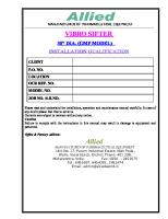
Wiring Diagram
TAD1640GE, TAD1640VE-B, TAD1641GE, TAD1641VE, TAD1641VE-B, TAD1642GE, TAD1642VE, TAD1642VE-B
37
System Information, EMS 1 2 3 4 5 6 7 8 9 10 11 12 13 14 15 16 17 18
Sensor, oil level Sensor, fuel pressure Sensor, crankhouse pressure Sensor, coolant temperature Sensor, coolant level Piston cooling pressure sensor Sensor, water in fuel Connector (not used) Extra stop J1939 CAN (bus) Battery negative Battery plus Voltage after key Stop button (press button) J1587 (bus) Jumper Aux stop VODIA output
19 20 21 22 23 24 25 26 27 28 29 30 31 32 33 34 35
Main relay Main circuit breaker 10 A Starter motor Battery (24 V) Alternator Pre-heating Relay pre-heating Unit injector (Cyl. 1-6) Sensor, flywheel Sensor, camshaft Sensor, charge air pressure/temperature Air filter indicator Sensor, oil pressure Connector A Connector B Control unit, EMS 2 Connector (not in usej)
Cable colors BL LBL BN LBN GN GR OR P R SB VO W Y
= = = = = = = = = = = = =
Blue Light blue Brown Light brown Green Grey Orange Pink Red Black Purple White Yellow
Cable cross section = 0.75 mm2 unless otherwise stated.
38
47701683 10-2012 © AB VOLVO PENTA
System Information, EMS TWD1643GE
47701683 10-2012 © AB VOLVO PENTA
39
System Information, EMS 1 2 3 4 5 6 7 8 9 10 11 12 13 14 15 16 17 18 19
Sensor, oil level Sensor, fuel pressure Sensor, crankhouse pressure Sensor, coolant temperature Sensor, coolant level Sensor, piston cooling pressure Sensor, water in fuel Connector (not in use) Extra stop J1939 CAN (bus) Battery minus Battery plus Voltage after key Stop button (press button) J1587 (bus) Jumper Aux stop VODIA input (diagnosis conn) Main relay
20 21 22 23 24 25 26 27 28 29 30 31 32 33 34 35 36 37
Main fuse breaker 10 A Starter motor Battery (24 V) Alternator Pre-heating Relay pre-heating Unit injector (Cyl. 1-6) Sensor, flywheel Sensor, camshaft Sensor, charge air pressure/temperature Air filter indicator Sensor, oil pressure Thermostat by-pass valve Wastegate valve Sensor, exhaust temperature Connection A Connection B Engine control unit, EMS 2
Cable colors BL LBL BN LBN GN GR OR P R SB VO W Y
= = = = = = = = = = = = =
Blue Light blue Brown Light brown Green Grey Orange Pink Red Black Purple White Yellow
Cable cross section = 0.75 mm2 unless otherwise stated.
40
47701683 10-2012 © AB VOLVO PENTA
4
GN/SB
3
BL/OR
SB 1,0
GR/OR
11
7
R
4
1
3
R 3
SB
SB
+
31
P
9
P2
1
4
2
11
BL/GN
24
CONNECTOR A
CONNECTOR B
GN/W
2
R 1,0
2
47 22
16
GN/R
BN/OR
P
25 1
4 R
SB
45 46
17
R 1,0 2
13
n
1
OR/SB
3
GR/GN
18
SB 1,0 GR/SB
1 R
SB
2
14
n
1
1
4
P
12
27
37 38 GR/SB
22
VO/SB
36
2
1
Y 1,0
40
28
GR/R
44 48
1
1
P
2
2
SB
SB
10
28 32
15
21
52 56
27 23 14
BN/OR Y 1,0
8
Y 1,0
GR/R Y 1,0
LBN Y 1,0
2
Y 1,0
SB
Y 1,0
4
SB
Y 1,0
SB 1,0 12 16
8
CAN 2 BL/GR Y 1,0 1 2
3 1 2
1 2
16
Cyl 6
3 4
Cyl 5
4
Cyl 4
3
1
4
3
1
3
1
3
2
Cyl 3
Cyl 2
Cyl 1
30 38
GN
4
2
4
2
4
52 56 h l
20 24
1 2 3 4 5 6 7
SB Y SB Y Y 1,0
1
2
2
28
59
62
29 25 37 h
OR 1,0
1
R/BL 1,5
Y 1,0 60
61
57 60
2
7
BN 1,0
23
Y 1,0
Y Y 1,0
Y/SB Y 1,0
BL/W Y 1,0
R/BL R/W
Y 1,0
R/BL 1,5 Y 1,0
6 1
8
61
b a 33 34
58 59
SB 1,5 Y/SB
R/BL 1,5 Y 1,0
SB 1,5
27
58
51 55 h l
57
3 4
4
STOP
R/BL 1,0
G
B-
12 3 4 5 B+
A B
BN 1,0 R 25
SB 25
20
18
5 6 7 8 R/BL 1,5
1 2
MAIN RELAY HOLD
W/SB
Y/W Y/W BL
SB 1,5 W
GR/Y GR/Y R/BL 1,5
R 2,5 R/BL 1,5
26 SB 2,5
BATT 1708 SWITCHED J1587
GR/SB
BATT+
W
H L
W/SB
7 10 12 3 4 5 6
SB 25
17
4231 4231
R
BATT-
3
R 25
31
M
R/W
CAN J1939
SB 1,5
2
1
Y/SB
11
W/SB SB OR 1,0
W SB 2,5 SB 2,5
-
47701683 10-2012 © AB VOLVO PENTA R 2,5 R 2,5
1
30
2
19
R
R 15
R/BL 1,5
Y/SB
1 2 3 4 5
30
85
5 86 87
System Information, EMS
TAD1650VE
P0004304
41
R/BN 1,0
System Information, EMS
1 2 3 4 5 6 7 8 9 10 11 12 13 14
Battery (24 V) Main switch Starter motor Alternator Main relay Aux stop Connector, engine interface Sensor, coolant temperature Sensor, charge air pressure/temperature VODIA socket (diagnosis socket) Connector, not used Sensor, crankhouse pressure Sensor, camshaft Sensor, flywheel
15 16 17 18 19 20 21 22 23 24 25 26 27 28
Sensor, piston cooling pressure Unit injector (cyl. 1-6) Pre-heat relay Circuit breaker Main automatic circuit breaker 10 A Pre-heater Sensor, coolant level Sensor, oil level Sensor, water in fuel Sensor, oil pressure Sensor, fuel pressure Internal EGR Control unit, EMS Wastegate valve
Cable colors BL LBL BN LB N GN GR OR P R SB VO W Y
= = = =
Blue Light blue Brown Light brown
= = = = = = = = =
Green Gray Orange Pink Red Black Violet White Yellow
Wire cross-section = 0.75 mm² unless otherwise stated.
42
47701683 10-2012 © AB VOLVO PENTA
System Information, EMS TAD1651GE
P0014126
47701683 10-2012 © AB VOLVO PENTA
43
System Information, EMS
1 2 3 4 5 6 7 8 9 10 11 12 13 14 15 16
Battery (orange indication) (24 V) Starter motor Alternator Main relay AUX stop Control unit, EMS2 Connector, engine interface Sensor, Coolant temperature Sensor, charge air pressure/temp. VODIA output Connector, no use Sensor, crankhouse pressure Sensor, camshaft Sensor, flywheel Sensor, piston cooling pressure Unit injector (cyl. 1-6)
17 18 19 20 21 22 23 24 25 26 27 28 29 30 31 32
Pre-heat relay Circuit breaker Fuse, 10 A Pre-heater Sensor, coolant level Sensor, oil level Sensor, water in fuel Sensor, oil pressure Sensor, fuel pressure Air filter indicator Electrical fan Valve, cold start Valve, wastegate Connection box Sensor, exhaust temperature
Cable colors BL LBL BN LB N GN GR OR P R SB VO W Y
= = = =
Blue Light blue Brown Light brown
= = = = = = = = =
Green Grey Orange Pink Red Black Purple White Yellow
Cabel cross section= 0,75 mm² unless otherwise stated.
44
47701683 10-2012 © AB VOLVO PENTA
System Information, EMS TAD1660VE, TAD1661VE, TAD1662VE TAD1660VE, TAD1661VE, TAD1662VE 0,75 SB
0,75 SB
0,75 SB 0,75 GR/OR
11
0,75 BL/OR
16
0,75 GN/R
0,75 SB
18
0,75 SB
0,75 R
27
12 16
0,75 BN/OR 1R
0,75 BL 5 1
M
1
0,75 VO
IC
24
0,75 GR
2 3 4
20 24
2 4 NCV
2 4 NCV
2 4 NCV
3 1 SV
3 1 SV
3 1 SV
3 1 SV
5
2 4 NCV
3 1 SV
23
2 4 NCV
3 1 SV
10
1Y
1Y
7 0,75 SB
0,75 Y 0,75 SB
22 21
1Y
0,75 P 0,75 BN/P
8
61
11
0,75 BL/W
38
34
0,75 W
25
0,75 BL 27 37 57
58
1,5 BL/R
0,75 BL/GR 1,5 BL/R
0,75 GN
0,75 W
0,75 Y/SB
10
1 OR
0,75 W/SB
0,75 BL/R
29
MAIN RELAY HOLD
33
0,75 W/SB
J1708 A J1708 B
0,75 R/W 1,5 BL/R
9
1,5 BL/R
1,5 BL/R 60
57
1,5 SB
J1939 H J1939 L BAT+MAIN REL.
1 2 3 4 5 6
8
H L
52 56
0,75 Y/SB
23
1 2 3 4 5 6 7
8
60
1Y
H L
1Y 1Y
6
62
1Y
0,75 W 0,75 SB
59
1Y
1Y
1Y
1Y
4 1 SB
0,75 GR/R
1/4
3 P
28
28 32
2 4 NCV
1Y
1 BL/R
0,75 R
0,75 SB
30
52 56
CYL.1
CYL.2
CYL.3
CYL.4
CYL.5
CYL.6
1Y
P
P
0,75 R
17
1R 1 SB
0,75 SB
44 48
24
5
2
40
1Y
1Y
1
0,75 BL/GN
36
1Y Y
1Y
31
37 38
n
0,75 OR/SB
1Y
4
45 46
0,75 GR/SB 0,5 GR/W
1Y
0,75 GN/W
35 39
0,75 OR/SB
n
26 25
15 29
P1/4
0,75 SB 0,75 OR 0,75 GN 0,75 BL
22
0,75 GN/GR
47
0,75 BN/OR
27
0,75 R
3
7
0,75 R
1 BN 0,75 GN/SB
49
31 11
1 SB 1R
0,75 SB 0,75 R
CONNECTOR B CONNECTOR A
P1/4
n
BC AED F
B C A E D F
B C A E D F
29
28
1 BN 7
1,5 SB
1,5 BL/R
58
0,75 BN
23 43
NTC
%RH
0,75 BL/W
1,5 SB 59
1,5 SB 61 51
0,75 Y/W
55
12
0,75 Y/GR
2,5 SB 2,5 R
1 BL/R
G
0,75 W 0,75 W/SB
0,75 R
25 SB
2,5 SB
4 SB
0,75 SB 0,75 W
SW
M
2,5 R
4R
17
2,5 R
18
4R
4 3 2 1
1 BN
14
16 4 3 2 1
25 R
47701683 10-2012 © AB VOLVO PENTA
4 SB
1 OR 1 BL/R
BAT.+ J1708 B BAT.CAN3 HIGH J1708 A CAN3 LOW
0,75 R
4R
1,5 R
19
85
R
86
25 SB
20
30
R
87 87a
21
15
SB
13 1 2 3 4 5 6
25 R
0,75 R 0,75 W/SB
J1939 H J1939 L BAT.BAT.+ BAT. SWITC. STOP J1708 A J1708 B
1 2 3 4 5 6 7 8
22
1 BL/R 1 SB
45
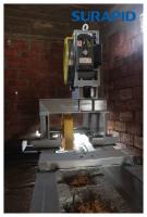
System Information, EMS
1 2 3 4 5 6 7 8 9 10 11 12 13 14 15 16
Sensor, oil level / temperature Sensor, fuel pressure Sensor, crankhouse pressure Sensor, coolant temperature Sensor, oil pressure Throttle Switch, coolant level Water in fuel connector Stop button VGT control valve 6-pole EATS connector 8-pole engine connector 6-pole diagnosis connector 2-pole EATS connector Main relay 4-pole pre-heat connector
17 18 19 20 21 22 23 24 25 26 27 28 29
Fuse, 10 A Fuse, 30 A Starter motor Main switch Battery Alternator Humidity sensor Unit injector (cyl. 1-6) Sensor, crank Sensor, camshaft Air filter indicator Electric fan Sensor, air inlet pressure / intake manifold temperature
30 Control unit EMS2
Cable colors BL LBL BN LBN GN GR OR P R SB VO W Y
= = = = = = = = = = = = =
Blue Light blue Brown Light brown Green Grey Orange Pink Red Black Purple White Yellow
Cable cross section = 0,75 mm² unless otherwise stated.
46
47701683 10-2012 © AB VOLVO PENTA
System Information, EMS
CIU (Control Interface Unit) CIU (Control Interface Unit)
47701683 10-2012 © AB VOLVO PENTA
47
System Information, EMS
1 2 3 4 5 6 7 8 9 10 11 12 13 14 15
Key switch, operating current (15+) RPM-potentiometer Tachometer (code 14) Oil pressure, instrument Oil temperature, instrument Coolant temperature, instrument Instrument illumination Idle contact, two position 1500/1800 contact, two position Start switch, spring return Stop switch, spring return Diagnosis contact, spring return Alarm, low oil pressure Alarm, high oil temperature Alarm, high coolant temperature
16 17 18 19 20 21 22 23 24 25 26 27 28 29 30
Alarm, low coolant level Fuel alarm Diagnostic lamp Overspeed indication (GE) Operation indicator Preheating indication Preheating contact 8-pin Deutsch connecting plug, engine interface Governor contact Battery voltage alarm Termination resistance 120 Ohm 8-pin Deutsch connecting socket Contact, engine protector disconnect Easy Link connector block Control Interface Unit (CIU)
Cable colors BL LBL BN LBN GN GR OR P R SB VO W Y
= = = = = = = = = = = = =
Blue Light blue Brown Light brown Green Grey Orange Pink Red Black Purple White Yellow
Cable cross section =0.75 mm2 unless other-wise stated.
48
47701683 10-2012 © AB VOLVO PENTA
System Information, EMS
DCU (Display Control Unit) 12345678 8 Y/W
2
GR/Y
3
SB 2,5
4
R 2,5
5
R/BL 2,5
6
BL 2,5
7
W
8
W/SB
Y/W GR/Y SB 2,5 R 2,5 R/BL 1,5 BL 2,5 W W/SB
1
Y/W GR/Y SB 2,5 R 2,5 R/BL 1,5 BL 2,5 W W/SB
11
3 1
D C 2 U 3
1
VO
1
4
2
R/Y
12345678 9
1 2 3 4 5 6 7 8 10
SB/Y
4
R/BL
5
Y
6
SB
7
GN/R
8
GN/Y
9
GN/SB
10
SB/VO
11
SB/GR
12
SB/W
1 3 2
5
6 7
P0004305
1 Stop contact
Cable Colors
2 Start contact
BL = Blue LBL = Lightblue BN = Brown LBN = Lightbrown GN = Green GR = Grey OR = Orange P = Pink R = Red SB = Black VO = Violet W = White
3 1-pin connector 4 Horn, buzzer alarm 5 Easy Link connector 6 RPM-potentiometer 7 Indicator engine operation 8 Deutsch 8-pin connector, engine interface 9 Deutsch 8-poligt connector, engine interface 10 Termination resistance 20 Ω 11 DCU (Display Control Unit)
47701683 10-2012 © AB VOLVO PENTA
Cable area = 0.75 mm2 unless otherwise specified.
49
Control System Installation, Connection
Control System Installation Connection General • The installation must be prepared for well and carried out with the greatest care.
• Secure the connecting cable between the engine
and instrument panel with clamps. Bear in mind that connector blocks must be mechanically secured so that they are not exposed to any pulling forces.
• The cables must not be run close by hot engine
components or close to any other heat source. Ensure that the cables are protected from mechanical wear, sharp edges and water splashes. If necessary, the cables can be run through conduits.
• As far as possible, avoid splices in the system wir-
ing. The cables and any splices must be accessible for inspection and service.
NOTICE! Connectors must be assembled “dry”, they must not be filled with petroleum jelly or similar.
50
47701683 10-2012 © AB VOLVO PENTA
Control System Installation, Connection
Power supply NOTICE! The engines are equipped with a 2-pole electrical system. This means that the positive and negative cables from the battery must be connected to the starter motor terminals. Thepositive cable from the battery may be run via a main switch to terminal 30 on the starter motor. The negative cable from the battery must be connected directly to terminal 31 on the starter motor. Refer to the illustration below.
30
31
P0003815
47701683 10-2012 © AB VOLVO PENTA
51
Control System Installation, Connection
Battery specifikation Max. battery 2x220 Ah (series connected), 1150 A CCA EN.
Battery charging Standard for all engines is that batteries are supplied with power from the alternator.
Battery cable cross-section area The total length (L) of the positive och negative cables determines the cable cross sectional area (A). Max L
(m) (ft)
8 26.2
10 32.8
13 42.6
Min A
(mm2) (in2)
70 0.11
95 0.15
120 0.19
WARNING! Due to fire risk, the cable area should never be less than 70 mm2 (0.1 inch2).
52
47701683 10-2012 © AB VOLVO PENTA
Control System Installation, Connection TWD1643GE NOTICE! All engines are equipped with a 2-pole electrical system. This means that the positive and negative cables from the battery must be connected to the starter motor terminals. The battery positive cable may be run via a main switch to the positive terminal. The battery negative cable must be connected directly to the negative terminal. Refer to the illustration below.
Battery specification Max. battery 2x220 Ah (series connected), 800 A CCA DIN.
Battery charging Standard for all engines is that batteries are supplied with power from the alternator
Battery cable cross-sectional area The total length (L) of the positive and negative cables determines cable cross sectional area (A). NOTICE! The negative cable may have a maximum length equivalent to that of the positive cable. Max L
(m) (ft)
8 26.2
10 32.8
13 42.6
Min A
(mm2) (in2)
70 0.11
95 0.15
120 0.19
WARNING! Due to fire risk, the cable area should never be less than 70 mm2 (0.1 inch2).
47701683 10-2012 © AB VOLVO PENTA
53
Control System Installation, Connection
CIU TAD1640GE, TAD1641GE, TAD1642GE, TAD1650GE, TAD1651GE, TWD1643GE
B
C
D
A
E
F P0004306
A 8-pin Deutsch connector, from wire harness to engine B Connectors, analog instruments C 3-pin Deutsch connector, Easy Link instrument
54
D For the connection cable, refer to the Instruments page 67 section. E 8-pin Deutsch connector F Extension cables, available in the following lengths: 3, 5, 7, 9, and 11 m
47701683 10-2012 © AB VOLVO PENTA
Control System Installation, Connection
Engine control Refer to System Information page 37 CIU NO = normally open NC = normally closed Start lock (system voltage OFF / ON) Engine system voltage start current (control unit) is 10 A. Ensure that other components in the installation are dimensioned for this current load. Start switch Switch type: closing (NO), spring loaded. Stop switch Switch type: closing (NO), spring loaded. The stop switch is energized during operations via a parameter setting. In this case use a normally closed (NC) switch. RPM potentiometer Nominal revolutions minus 120 rpm: 0.3–1.9 V (preset value 1.17 V) Nominal revolutions plus 120 rpm: 1.9–4.7 V (preset value 4.5 V)
A
A B C P0005827
1.17 V
2.84 V
4.5 V
P0005828
47701683 10-2012 © AB VOLVO PENTA
55
Control System Installation, Connection 1500/1800 rpm switch Two-position contact. This function allows a frequency change from 50 to 60 Hz. Idle switch Two-position contact. Closed contact provides idle rpm. Droop value switch Two-position contact. The switch must be closed to provide rpm droop value. Primary control switch Two-position contact. Contact, pre-heating Two-position contact.
56
47701683 10-2012 © AB VOLVO PENTA
Control System Installation, Connection
CIU TAD1640VE-B, TAD1641VE, TAD1641VE-B, TAD1642VE, TAD1642VE-B, TAD1643VE, TAD1650VE
A 8-pin Deutsch connector, from wire harness to engine B Connectors, analog instruments C 3-pin Deutsch connector, Easy Link instrument
47701683 10-2012 © AB VOLVO PENTA
D For the connection cable, refer to the Instruments page 67 section. E 8-pin Deutsch connector F Extension cables, available in the following lengths: 3, 5, 7, 9, and 11 m
57
Control System Installation, Connection
Engine control Refer to System Information page 37 CIU NO = normally open NC = normally closed
A
Start lock The start lock switch is used to connect the system power, pre-heating and start and stop functions.
B
Engine system voltage start current (control unit) is 10 A. Ensure that other components in the installation are dimensioned for this current load.
C
D
P0003965
A
Stop contact
B
ON contact
C
Start lock
D
Pre-heating contact
Start lock positions
I
Position 0: engine switched OFF Position I: system voltage ON Position II: pre-heating ON (spring return) Position III: start motor ON (spring return) Position S: stop function ON (spring return)
P0003966
A
Pre-heating
B
Start
C
Batt +
D
15 start lock
E
Stop
58
A B C D E
47701683 10-2012 © AB VOLVO PENTA
Control System Installation, Connection Control switch Two-position contact. Accelerator pedal Idle: 0.3 1.9 V (preset value 1.17 V) Full throttle: 1.9 4.7 V (preset value 4.5 V) If an accelerator pedal with different resistance and voltage values is used, the control unit must be re-calibrated using the parameter tool; refer to Connection of special tool VODIA page 71.
A B
Idle switch The accelerator pedal has an integral idle switch that acts as an emergency device if the accelerator pedal potentiometer becomes defective. When the accelerator pedal is depressed, a contact is closed and the engine increases in steps to 80 percent of maximum rpm. When the accelerator pedal is released, the contact is opened and the engine slows to idle immediately.
P0004058
47701683 10-2012 © AB VOLVO PENTA
59
Control System Installation, Connection
DCU
B
C A
P0005826
A
8-pin connector from the engine wire harness.
B
3-pin Deutsch connector, Easy Link instrument
C
Connectors, analog instruments (options)
60
47701683 10-2012 © AB VOLVO PENTA
Control System Installation, Connection DCU (Display Control Unit) The DCU is connected via the 8-pin databus connector block. Display (optional) Switch type: closing (NO), spring loaded. Stop switch (optional) Switch type: closing (NO), spring loaded. Warning and control lamps (options) Running indication: Max. power 3 W Voltage 24 V
47701683 10-2012 © AB VOLVO PENTA
61
Control System Installation, Connection
Easy Link Instruments For parallel connection of up to 20 extra VDO instruments. The instruments will automatically find their own parameter group from the databus. Maximum Easy Link cable length is 3 m.
The following instruments are available: GE engines
• Tachometer/operating hours • Coolant temperature • Oil pressure • Oil temperature • Battery voltage VE engines
• Tachometer/operating hours • Coolant temperature • Oil pressure • Oil temperature • Charge air pressure • Battery voltage • Alarm monitor
62
47701683 10-2012 © AB VOLVO PENTA
Control System Installation, Connection
Rpm-potentiometer TAD1640GE, TAD1641GE, TAD1642GE, TAD1650GE, TAD1651GE, TWD1643GE Genset engines The values from the rpm potentiometer in, in or output signal from the connection to an external load distribution system can be set in the DCU. Nominal revolutions minus 120 rpm: 0–10 V (preset value 1 V) Nominal revolutions plus 120 rpm: 0–10 V (preset value 9 V) It is possible to invert the signal; see diagram.
A
A
B
B
C P0005824
C 1V
5V
9V P0005825
1V
5V
A
Nominal revolutions + 120 rpm
A
Nominal revolutions + 120 rpm
B
Nominal revolutions (1500/1800 rpm)
B
Nominal revolutions (1500/1800 rpm)
C
Nominal revolutions - 120 rpm
C
Nominal revolutions - 120 rpm
47701683 10-2012 © AB VOLVO PENTA
9V
63
Control System Installation, Connection TAD1641VE, TAD1642VE, TAD1643VE, TAD1650VE Versatile engines It is possible to invert the throttle signal; see the diagram below.
P0005815
P0005816
Max. potentiometer value: 0–10 V (preset value 9V) Min. potentiometer value: 0–10 V (preset value 1V)
64
47701683 10-2012 © AB VOLVO PENTA
Control System Installation, Connection
Warning and Indication Lamps The warning and control lamps below are available. Specification for all lamps: Max. power 3 W Voltage 24 V Refer to the CIUSystem Information page 37.
• Alarm, low oil pressure • Alarm, high oil temperature • Alarm, high coolant temperature • Alarm, low coolant level • Alarm, low fuel level • Alarm, low battery voltage • Diagnostic lamp • Pre-heat indicator
47701683 10-2012 © AB VOLVO PENTA
65
Control System Installation, Connection The warning and control lamps below are available. Specification for all lamps: Max. power 3 W Voltage 24 V Refer to the CIUSystem Information page 37.
• Alarm, low oil pressure • Alarm, high oil temperature • Alarm, high coolant temperature • Alarm, low coolant level • Alarm, low fuel level • Alarm, low battery voltage • Diagnostic lamp • Pre-heat indicator
66
47701683 10-2012 © AB VOLVO PENTA
Control System Installation, Connection
Instruments Easy Link Instrument (option) Refer to the System Information page 37 for the engine concerned. For parallel connection of up to 20 extra VDO instruments. The instruments will automatically find their own parameter group from the databus. Maximum Easy Link cable length is 3 m. The following instruments are available:
• Tachometer/operating hours • Coolant temperature • Oil pressure
P0005054
• Oil temperature • Battery voltage Retaining collar
Securing bracket
P0005053 P0005052
Extension cable, 3-pole, 1 m
P0005051
47701683 10-2012 © AB VOLVO PENTA
A
3-pin connector
B
3-pin connectors
C
CIU wiring harness
67
Control System Installation, Connection
Instrument, analog (option) Refer to the System Information page 37 for the engine concerned. Tachometer Use Volvo Penta standard tachometer, graduations 0– 2600 rpm. Setting code 14. Refer to installation instructions.
P0003961
Oil pressure gauge Use Volvo Penta oil pressure gauge, graduations 0– 10 bar (0–145 psi).
P0003961
Oil temperature gauge Use Volvo Penta oil temperature gauge, graduations 40–150 °C (104–302 °F).
P0003961
68
47701683 10-2012 © AB VOLVO PENTA
Control System Installation, Connection Coolant temperature gauge Use Volvo Penta oil temperature gauge, graduations 40–150 °C (105–300 °F). Diagnostics switch Switch type: closing (NO), spring loaded. For reading fault codes, refer to the Calibration and Settings page 92 chapter. Contact, pre-heater Switch type: closing (NO), spring loaded. This contact activates the pre-heating. P0003961
47701683 10-2012 © AB VOLVO PENTA
69
Control System Installation, Connection
Synchronizing Engine Speed TAD1640GE, TAD1641GE, TAD1642GE, TWD1643GE Synchronization/load distribution The system is adapted for GAC synchronization and load distribution. Use the EAM122 interface module when connecting to this system. When this system is used, voltage levels must be adjusted simultaneously with VODIA, according to the below. NOTICE! The EAM122 interface module is not sold by Volvo Penta. Contact a GAC (Governors of America Corporation) dealership.
A B C
A B C 0.7 V
2.75 V
4.8 V
P0005829
A
Nominal revolutions +120 rpm
B
Nominal revolutions (1500/1800 rpm)
C
Nominal revolutions –120 rpm
P0003964
A
Rpm control (GN/NO)
B
Rpm control (GN/SB)
C
Contact to (R/BL 1.5)
70
47701683 10-2012 © AB VOLVO PENTA
Calibration and Settings, Parameter Setting
Calibration and Settings Parameter Setting Connection of special tool VODIA Connection of special tool VODIA TAD1640GE, TAD1641GE, TAD1642GE, TAD1641VE, TAD1642VE, TAD1643VE
Function It is possible to read and adjust parameters with the VODIA tool, part no.3838619, as described in the following pages. The VODIA tool is connected to the diagnostics socket, a 6-pin connector; refer to VODIA user instructions for instructions.
P0005817
TAD1650VE
P0001170
47701683 10-2012 © AB VOLVO PENTA
71
Calibration and Settings, Parameter Setting
Adjustable parameters TAD1640GE, TAD1641GE, TAD1642GE, TAD1650GE, TAD1651GE, TWD1643GE NOTICE! Some parameters require special authorization. Primary regulator mode Selects the regulator to be used when the regulator contact is closed. Alternative modes: ”Isochronous” or ”Droop value” Preset mode: ”Isochronous” PTO regulator gradient is used The gradient is defined either by a droop value in percent if the Regulator roop value parameter is equal to zero or Nm/rpm if the Regulator gradient parameter is equal to zero. Regulator droop value Selects the droop value magnitude to be used when droop value is activated (percent). Min. value: 0 % Preset value: 4 % Max. value: 8 % Stop function The CIU unit stop signal is energized during “operations” or “stop”. Preset mode: ”Stop” Lamp test This parameter determines if a lamp test is to be performed when the system is started. Alternative modes: “Off” or “On” Preset mode: “On”
Indicated engine rpm inverted value Selects the regulator to be used when the regulator contact is closed. Alternative engine revolutions: 1500 rpm or 1800 rpm. Preset rpm: dependent on the specification ordered. Maximum engine revolutions (CIU) Potentiometer signal voltage on the CIU unit corresponding to nominal revolutions (1500/1800 rpm) plus (+) 120 rpm. Min. value: 1.90 V Preset value: 4.50 V Max. value: 4.70 V Pre-heating for ignition Selects whether pre-heating and post heating is to be activated directly when the ignition is turned on. The pre-heating and post heating periods are dependent on coolant temperature. If the parameter is in ”Off” mode, pre-heating and post heating must be activated manually via the ignition lock or pre-heater button. Alternative modes: “Off” or “On” Preset mode: “Off”
Idling speed Setting idle revolutions. Min. value: 600 rpm Preset value: 900 rpm Max. value: 1200 rpm
72
47701683 10-2012 © AB VOLVO PENTA
Calibration and Settings, Parameter Setting
Adjustable parameters TAD1640VE-B, TAD1641VE, TAD1641VE-B, TAD1642VE, TAD1642VE-B, TAD1643VE, TAD1650VE, TAD1660VE, TAD1661VE, TAD1662VE NOTICE! Some parameters require special authorization. Inverted regulator mode Select if droop value is to be active. Alternative modes: “No droop value” or “Variable droop value” Preset mode: “Fixed droop value” Regulator mode Select if droop value is active. Alternative modes: “Off” or “No” Preset mode: ”No” Primary regulator mode Selects the regulator to be used when the regulator contact is closed. Alternative modes: ”Isochronous” or ”Droop value” Preset mode: ”Isochronous” Regulator gradient Determines the droop value to be used (gradient) Min. value: 10 Nm/revolution Preset value: 25 Nm/revolution Max. value: 128 Nm/revolution Stop function Preset mode: ”Stop” CIU stop function The CIU unit stop signal is energized during “Operations” or “Stop”. Preset mode: ”Stop”
Idling speed Setting idle revolutions. Min. value: 550 rpm Preset value: 600 rpm Max. value: 800 rpm TAD1650VE: 700 rpm Idle voltage (CIU) Throttle control input signal voltage to corresponding idle at the CIU unit. Min. value: 0.30 V Preset value: 1.17 V Max. value: 1.90 V Voltage max. rpm (CIU) Throttle control input signal voltage to corresponding full throttle at the CIU unit. Min. value: 1.90 V Preset value: 4.50 V Max. value: 4.70 V Pre-heating for ignition Selects if pre-heating is to be activated directly the ignition is turned on. If the parameter is in ”Off” mode, pre-heating and post heating must be activated manually via the ignition lock or pre-heater button. Alternative modes: “Off” or “On” Preset mode: “Off”
Lamp test This parameter determines if a lamp test is to be performed when the system is started. Alternative modes: “Off” or “On” Preset mode: “On”
47701683 10-2012 © AB VOLVO PENTA
73
Calibration and Settings, Parameter Setting
Adjustment of speed regulator TAD1640GE, TAD1641GE, TAD1642GE, TAD1650GE, TAD1651GE, TWD1643GE NOTICE! The regulator has a basic factory setting that is optimized to suit the most common generator set applications. Use the VODIA tool (including EMS software), to read and adjust the P, I and D sections of the engine speed regulator. The adjustment is made to give more stable and even running of the engine and to adapt the engine to the specific generator set application. PID = Proportional, Integrating, Differentiating A = rpm B = time 1 = Demanded engine speed 2 = True engine speed
A
P-value 1
Amplifier (Gain), amplification of the difference between the actual value and the set value. A reduced value (Fig.1) gives a weaker responce to speed deviations. Reduce the P-value to reduce oscillations arising from large differences in speed/load application.
2
B
Fig. 1 P0016983
Fig 1 P-value too low
A 1 An increased value (Fig 2) gives a shorter response time. Increase the P-value for faster compensation of large differences in speed/load.
2 Fig. 2
B
Fig 2 P-value too high
P0016984
74
47701683 10-2012 © AB VOLVO PENTA
Calibration and Settings, Parameter Setting
I-value A
Stabilizes (stability), reacts to the time of the speed deviation.
1
A reduced value (Fig.3) increases the time taken by the system to respond after a load change. Reduce the I-value to reduce the oscillations that arise with slowly increasing loading.
2
B Fig. 3
Fig 3 I-value too low
P0016985
A 1 An increased value (Fig 4) gives a shorter response time. Increase the I-value to provide better load response for slowly increasing loads.
2
Fig 4 B
I-value too high or D-value too low
Fig. 4 P0016986
D-value Compensates (derivative). Reacts to fast changes of engine speed/load. A-reduced value (Fig 4) gives a greater sensivity to fast changes of engine speed/load. Reduce the Dvalue ro reduce oscillations caused by fast changes.
A 1
An increased value (Fig 5) gives a reduced sensitivity to fast load changes. increase the D-value to provide a better ability to compensate for fast changes.
2
B Fig. 5 P0016987
47701683 10-2012 © AB VOLVO PENTA
Fig 5 D-value too high
75
Calibration and Settings, Parameter Setting
Alarm limits TAD1640GE, TAD1641GE, TAD1642GE, TAD1650GE, TAD1651GE, TWD1643GE Alarm threshold, high oil temperature A warning lamp is lit at this temperature. Min. value: 120 °C (248 °F) Preset value: 125 °C (257 °F) Max. value: 130 °C (266 °F) Alarm threshold, high coolant temperature A warning lamp is lit at this temperature. Min. value: 95 °C (203 °F) Preset value: 98 °C (208 °F) Max. value: 103 °C (217 °F)
Overspeed limit Percent above normal revolutions at which the overspeed warning is activated. Min. value: 0 % Preset value: 20 % Max. value: 20 %
Alarm limits TAD1640GE, TAD1640VE-B, TAD1641GE, TAD1641VE, TAD1641VE-B, TAD1642GE, TAD1642VE, TAD1642VE-B, TAD1643VE Alarm threshold, high oil temperature A warning lamp is lit at this temperature. Min. value: 120 °C (248 °F) Preset value: 125 °C (257 °F) Max. value: 130 °C (266 °F)
Alarm threshold, high coolant temperature A warning lamp is lit at this temperature. Min. value: 95 °C (203 °F) Preset value: 98 °C (208 °F) Max. value: 103 °C (217 °F)
Alarm limits TAD1640VE-B, TAD1641VE, TAD1641VE-B, TAD1642VE, TAD1642VE-B, TAD1643VE, TAD1650GE, TAD1650VE, TAD1651GE, TAD1660VE, TAD1661VE, TAD1662VE, TWD1643GE Alarm threshold, high oil temperature A warning lamp is lit at this temperature. Min value: 120 °C (248 °F) Preset value: 125 °C (257 °F) Max value: 130 °C (266 °F)
76
Alarm threshold, high coolant temperature A warning lamp is lit at this temperature. Min value: 95 °C (203 °F) Preset value: 98 °C (208 °F) Max value: 107 °C (217 °F)
47701683 10-2012 © AB VOLVO PENTA
Calibration and Settings, Parameter Setting
Engine protection TAD1640GE, TAD1641GE, TAD1642GE, TAD1650GE, TAD1651GE, TWD1643GE Oil temperature Determines whether engine protection is to be activated in respect of high oil temperature. A fault code is registered and the engine is shut down. Alternative modes: “Yes” or “No” Preset mode: “Yes”
Oil pressure Determines whether engine protection is to be activated in respect of low oil pressure. A fault code is registered and the engine is shut down. Alternative modes: “Yes” or “No” Preset mode: “Yes”
Coolant temperature Determines whether engine protection is to be activated in respect of high coolant temperature. A fault code is registered and the engine is shut down. Alternative modes: “Yes” or “No” Preset mode: “Yes”
Piston cooling pressure Determines whether engine protection is to be activated in respect of low piston cooling pressure. A fault code is registered and the engine is shut down. Alternative modes: “Yes” or “No” Preset mode: “Yes”
Coolant level Determines whether engine protection is to be activated in respect of low coolant level. A fault code is registered and the engine is shut down. Alternative modes: “Yes” or “No” Preset mode: “Yes”
Crankcase pressure Determines whether engine protection is to be activated in respect of high crankcase pressure. A fault code is registered and the engine is shut down. Alternative modes: “Yes” or “No” Preset mode: “Yes”
Charge air temperature Determines whether engine protection is to be activated in respect of high charge air temperature. A fault code is registered and the engine is shut down. Alternative modes: “Yes” or “No” Preset mode: “Yes”
Overspeed warning shutdown Determines whether engine protection is to be activated in respect of overspeed. A fault code is registered and the engine is shut down. Alternative modes: “Yes” or “No” Preset mode: “Yes”
Charge pressure Determines whether engine protection is to be activated in respect of high charge air pressure. A fault code is registered and the engine is shut down. Alternative modes: “Yes” or “No” Preset mode: “Yes”
Exhaust temperature (only TWD1643GE) Determines whether engine protection is to be activated in respect of high exhaust temperature. A fault code is registered and the engine is shut down. Alternative modes: “Yes” or “No” Preset mode: “Yes”
47701683 10-2012 © AB VOLVO PENTA
77
Calibration and Settings, Parameter Setting
Engine protection TAD1640VE-B, TAD1641VE, TAD1641VE-B, TAD1642VE, TAD1642VE-B, TAD1643VE, TAD1650VE, TAD1660VE, TAD1661VE, TAD1662VE Oil temperature Determines whether engine protection is to be activated in respect of high oil temperature. A fault code is registered and the engine is shut down. TAD1650VE: a fault code is registered and an orange or red warning lamp is lit. Alternative modes: “Yes” or “No” Preset mode: “Yes” Coolant temperature Determines whether engine protection is to be activated in respect of high coolant temperature. A fault code is registered and the engine is shut down. Alternative modes: “Yes” or “No” Preset mode: “Yes” Coolant level Determines whether engine protection is to be activated in respect of low coolant level. A fault code is registered and the engine is shut down. TAD1650VE: a fault code is registered and an orange warning lamp is lit. Alternative modes: “Yes” or “No” Preset mode: “Yes” Charge air temperature Determines whether engine protection is to be activated in respect of high charge air temperature. A fault code is registered and the engine is shut down. Alternative modes: “Yes” or “No” Preset mode: “Yes”
Oil pressure Determines whether engine protection is to be activated in respect of low oil pressure. A fault code is registered and the engine is shut down. Alternative modes: “Yes” or “No” Preset mode: “Yes” Piston cooling pressure Determines whether engine protection is to be activated in respect of low piston cooling pressure. A fault code is registered and the engine is shut down. Alternative modes: “Yes” or “No” Preset mode: “Yes” Crankcase pressure Determines whether engine protection is to be activated in respect of high crankcase pressure. A fault code is registered and the engine is shut down. Alternative modes: “Yes” or “No” Preset mode: “Yes” ECU temperature (only TAD1650VE) Determines whether engine protection is to be activated in respect of high control unit temperature. A fault code is registered and an orange or red warning lamp is lit.
Charge pressure Determines whether engine protection is to be activated in respect of high charge air pressure. A fault code is registered and the engine is shut down. Alternative modes: “Yes” or “No” Preset mode: “Yes”
78
47701683 10-2012 © AB VOLVO PENTA
Calibration and Settings, Parameter Setting
CAN bus settings Background With new emission legislations the requirements on customer panels increases and a document describing what needs to be implemented in the OEM CAN panels is needed.
Requirements on OEM panels There is one message that has to be sent to the VP EECU and that is the VP status message. See section VP STATUS MESSAGE: OC FF 46 11. Without this message the EECU will set a fault code on the CAN bus and disregard more communication. Engine interface connector (EIC) The EIC contains 8 pins with the following functions: 1 CAN High 2 CAN Low 3 Battery minus 4 Battery plus 5 Battery after key 6 Extra stop 7 J1587A 8 J1587B This is where any CAN panel shall connect to battery plus and battery minus in order to be powered. Battery after key and extra stop shall get the positive voltage from pin 4 (battery plus) when powered.
47701683 10-2012 © AB VOLVO PENTA
79
Calibration and Settings, Parameter Setting Battery after key - signal The battery after key - signal is a “wake up” signal to the EMS. When this pin get powered the main relay will be activated which will power the EMS and the EMS will start to communicate. This pin should have power for as long as the EMS is supposed to communicate. The EMS will hold this relay even without getting power via this signal once the software is up and running. However, in order to avoid problems in the aftermarket, it shall always be power on this pin when the EMS is supposed to communicate. NOTICE! The battery after key signal can be configured via VP aftermarket tool. So that the engine will stop if power is removed from the pin. (Pin 5 in the 8pole Engine Interface Connector; EIC). It shall also always be possible to power this pin without having to start the engine in order to be able to work on the engine with after market tools.
80
47701683 10-2012 © AB VOLVO PENTA
Calibration and Settings, Parameter Setting Battery plus and minus The battery plus and minus in the EIC is connected to the battery via the starter motor. I.e. these pins in the EIC are outputs that are intended to power other CAN nodes connected to the engine CAN network. Failure to do this can cause EECU damages. Power down When the EMS should be deactivated the power on battery after key should be removed and a stop signal should be sent. This will let the EMS save the data it needs to save and perform a controlled power down. The VP status message should be sent until the EMS stops to communicate in order to avoid unnecessary error codes. NOTICE! The stop signal can be either the available CAN stop or the extra stop in the EIC or with the ignition key. In both cases the stop signal should only be active for a limited period of time.
47701683 10-2012 © AB VOLVO PENTA
81
Calibration and Settings, Parameter Setting VP STATUS MESSAGE: OC FF 46 11 The VP status message is a VP proprietary J1939 message that the engine always needs to receive for as long as it is awake. All necessary engine functionality can be controlled via this message. ID: 0C FF 46 11 Byte: 1
bits 8-7
Idle speed select
bits 6-5
Governor mode request
bit 4-3
Stop request
bit 2-1
Start request
bits 8-7
Engine protection override
bits 6-5
Preheat request
bit 4-3
Diagnosis request
bit 2-1
Frequency select
Byte: 3
all bits
Accelerator pedal position
Byte: 4
all bits
Accelerator pedal positon
Byte: 5
bits 2-1
Fuel disable request
Byte: 2
Table1: The contents of the VP status message. Power up The EECU needs to receive the VP status message within 500ms of power up. If this message is not sent the EMS will set an error code on the CAN bus communication. It is recommended that the OEM CAN panel always send this message when it is powered and that the panel also controls when the engine should be ignited. See battery after key - signal for more information regarding the ignition function.
82
47701683 10-2012 © AB VOLVO PENTA
Calibration and Settings, Parameter Setting Stop functionality There are several ways of stopping a VP engine and one or two of the following shall be used: 1 Stop request via VP status on CAN. 2 Extra stop signal in EIC. (Engine Interface Control) 3 TAD1660: Ignition Off None of these stop signal should be continuously active when the engine is standing still with power to the EMS. Sending a continuously active stop signal with ignition on could damage the EMS. See VP status message for more information about how to send the CAN stop request.
StopRequest_vPStatus 0
Engine Speed ERR
Active
Stop signal active < 0,5s
Inactive P0013957
Figure 2: An example on stopping an engine with a short active stop signal.
47701683 10-2012 © AB VOLVO PENTA
83
Calibration and Settings, Parameter Setting Start functionallety There are two ways to start the engine and they are: 1 Sending a start request via the VP status message on CAN. 2 Having the EMS powered and turn the engine. For more information regarding the start request function see VP status message. There are four things that will stop the engine from cranking: 1 The start request signal is deactivated. 2 There is a stop signal activated. 3 The engine rpm is high (this means that the engine has started) 4 The cranking time has been to long (The EMS will protect the starter from overheating by not allowing to crank to long).
StartRequest_vPStatus 0
ERR
Start request activated
Active Starter motor turning engine
Start cranking
Engine accelerates
Inactive P0013958
Figure 3: A succesfull start attempt.
84
47701683 10-2012 © AB VOLVO PENTA
Calibration and Settings, Parameter Setting Accelerator Pedal Position The accelerator pedal position part of the VP status message is two bytes long and the range is 0 - 100%. For VE engines 0% means idle speed and 100% means maximum available speed at the current engine load. If a mobile VE engine does not receive any speed request it will got to idle speed. For GE engines 0% means nominal speed -120 rpm and 100% means nominal speed +120 rpm. In order to request the engine to run at nominal speed (1500 or 1800 rpm) the pedal position needs to be set to 50%. If a GE engine does not receive any speed request it will stay at the last requested speed. Message
Byte 1
VP70_VP_Status 00
Byte 2
Byte 3
Byte 4
Byte 5
Byte 6
Byte 7
Byte 8
00
FF
01
00
00
00
00
Table 2: An example of the VP status message In the table above there is an example of how the VP status message can be sent. The pedal position part is byte 3 and 4 and byte 4 is the most significant byte which means that in this case the pedal position is 0x01FF. Sins the resolution of this signal is 100/1023% / Bit, the pedal position in percent is calculated as follows: Pedal position = 511 x (100/1023) ≈50%
47701683 10-2012 © AB VOLVO PENTA
85
Calibration and Settings, Parameter Setting Error code presentation VP engines uses standard J1939 frames for sending error codes. VP EMS engines uses conversion method 4 when sending error codes on the CAN bus. The CAN panels always have to display SPN and FMI numbers on any active error code. It can be completed with a generic name for the error code but the SPN and FMI must also be displayed. Single active error code For single active error codes the DM (Active Diagnostic Trouble Codes) is used. Table 3 shows how a DM1 signal from an EMS engine is sent. DM1
Byte 1
Byte 2
Byte 3
Byte 4
Byte 5
Byte 6
Byte 7
Byte 8
18FECA00x
04
FF
64
00
12
01
FF
FF
Table 3: Example on how an EMS engine sends the error codes.
Byte
Value (Hex)
Value (Dec)
Description
1
0x04
4
Byte 1 includes lamp colour and 4 corresponds do “yellow” lamp.
2
0xFF
255
Not used.
3
0x64
100
First and least significant byte of SPN.
4
0x00
0
Second byte of SPN.
5
0x12
18
Bits 6-8 are the most significant bits of SPN. Bits 1-5 are the FMI value.
6
0x01
1
Bit 8 is the SPN conversion method. Bits 1-7 are the occurrence counter.
7
0xFF
255
Not used
8
0xFF
255
Not used Table 4: How to interpret the VP DM1 message.
86
47701683 10-2012 © AB VOLVO PENTA
Calibration and Settings, Parameter Setting Multiple active error codes If there are multiple simultaneously active error codes the broadcast announce (TP.CM_BAM) and the data transfer messages (TP.DT) are used in order to send all error codes. The CAN panel shall be able to display up to 10 simultaneously active error codes. All of them do not need to be displayed at the same time but it shall be possible to scroll through them. NOTICE! When the CAN diagnostics uses the transport protocol, the standard polling is not supported, meaning that no “request to send” is transmitted and no “clear to send” is being received. No “end of message ack” is received. The EMS will send a BAM and directly there after follow by DM1 / DM2. Engine protection functionality VP engines are designed to protect themselves from being damaged by e.g. overheating or low oil pressure and will take action in order to avoid engine damage. No action should be taken by the CAN panel to stop the engine in case an engine protection error is sent. NOTICE! The engine protects itself from being damaged but it does not consider the surrounding it is installed in.
47701683 10-2012 © AB VOLVO PENTA
87
Calibration and Settings, Parameter Setting
More available control functions There are other possibilities than the VP status/pedal position message in order to control the engine speed. Torque speed control - TSC1 (0C 00 00 03/11/E6) The TSC1 message has priority over the pedal position that is sent with the VP status message. With the TSC1 message with source address 0x03, 0x11, 0xE6, the engine speed and torque can be continuously controlled. With the TSC1 message with the source address 0x11 it is possible to limit the available torque or speed from the engine.
Nm
Torque Limit 2000 1800 1600 1400 1200 1000 800 600 400 200 0 750 950 P0013959
1150 rpm
1350
1550
1750
1950
Figure 4: The yellow graph shows the available engine torque when the TSC1 signal sets to 80% in the torque limiting factor. The picture shows an example on how an engine would react when limiting the torque via the TSC1 message.
Start battery test Whit the fuel disable request in the VP status message, it is possible to perform a start battery test.
88
47701683 10-2012 © AB VOLVO PENTA
Calibration and Settings, Parameter Setting
Special requirements with EATS The engines equipped with exhaust after treatment systems have some more requirements regarding which messages that includes error code information. DEF level The DEF level is broadcasted on the J1939 bus via SPN 1761. SPN 1761 will show a value between 0 100% DEF level diagnostics The DEF level diagnostics are sent via two different SPN numbers. These SPN numbers are SPN 5245 and 5246 and they are included in the message AT1TI (PGN 65110). See table 5 for location of these signals in AT1TI. SPN
Start byte
Start bit
Length (bits)
5245
5
6
3
5246
6
6
3 Table 5: SPN 5245 and 5246 in PGN 65110 (AT1Ti). If the DEF level is low SPN 5245 will be sent with a value that shows how severe the low level is as described in table 6.
SPN 5245 Value
Severity Level
1
DEF/AdBlue level low. Solid signal.
4
DEF/AdBlue level empty. Flashing with 1Hz. Table 6: SPN 5245 and 5246 in PGN 65110 (AT1Ti). There are different inducement levels to motivate the operator to not use the engine when the EATS does not work properly. The inducement level active is communicated via SPN 5246 as described in table 7.
SPN 5246 Value
Inducement Level
3
Engine derate
4
Pre severe inducement
5
Severe inducement
6
Temporary override of inducement Table 7: SPN 5245 and 5246 in PGN 65110 (AT1Ti). DEF symbol If a symbol is used in the display for any SCR related SPN, the symbol shown in figure 5 has to be used.
P0013960
47701683 10-2012 © AB VOLVO PENTA
89
Calibration and Settings, Parameter Setting Figure 5: The symbol used for DEF functions.
Stop functionality The stop function in EMS2 works in two different ways if stop function is set to “energized to run”, described as follows, (picture). ETR stands for Energized To Run, and ETS stands for Energized To Stop
EMS 2
EMS 2.2 (Tier 4)
Engine: 164X/165X
Battery switch Stop
1 2 3 4 5 6 7 8
ETR / ETS
Engine 1660/164X VE-B
Battery switch Stop
1 2 3 4 5 6 7 8
ETR / ETS
Fig. 5 P0016988
90
47701683 10-2012 © AB VOLVO PENTA
Calibration and Settings, Parameter Setting EMS-2 extra stop On EMS2 engines the extra stop is level triggered as shown in figure 7. The default setting is “Energized to stop” which means that when there is power on this pin the engine will stop and it will not be able to start until the stop signal is deactivated. If the parameter “Stop function EMS, energized to” is set to run, there needs to be battery power on this pin in order for the engine to be able to run.
Engine Running Energized to stop
Running Stopped Battery + Open Circut
No stop
Battery +
STOP!
Energized to run Open Circuit P0013962
Figure 7: The extra stop functionallety on EMS2 engines.
Never have a stop signal being continuously sent to a powered control unit. If there is a continuous active stop signal over time, it could damage the engine control unit. Figure 1 shows that the stop signal should be sent as a pulse signal. The voltage to the stop signal should come from pin 4 in the engine interface connector.
47701683 10-2012 © AB VOLVO PENTA
91
Calibration and Settings, Diagnostic Function
Diagnostic Function The diagnostic function monitors and controls that the EMS system functions normally. The diagnostic function has the following tasks:
• Detecting and locating disturbances • Reporting detection of disturbances • Providing guidance when fault tracing NOTICE! With the DCU:n it is possible choose the language that the information is presented in. If the diagnostic function detects a disturbance in the system, this is reported using fault codes via the instruments. Both active (unrectified) and passive (rectified) faults are stored in the control unit. Refer to the “Operation” heading for reading fault codes/fault messages. All fault codes and fault messages are found in the fault code list, with information about the reason, reaction and measures to be taken. Refer to Fault Code Register. NOTICE! All instruments are optional.
Effect on engine Engines are affected differently, depending on the severity of the fault discovered by the diagnostic function. A fault message in the form of a fault code is always generated when a malfunction is discovered by the diagnostic function. Engines are affected differently, depending on the severity of the fault:
• The engine is not affected • Engine goes to idle • Engine torque is restricted to a certain amount • Engine is stopped
92
47701683 10-2012 © AB VOLVO PENTA
Calibration and Settings, Diagnostic Function
Active and Inactive Faults Active faults At the same time, the fault is stored in the control unit memory. When the fault has been attended to and the ignition is switched off and on again, the fault disappears as active.
Inactive faults •
DCU – the fault is indicated as passive
•
CIU – the diagnostic lamp goes out
•
DU – the fault message disappears (inactive faults cannot be read out)
•
“Easy Link” – the lamp on the alarm panel goes out
DCU (Display Control Unit) •
text !! ENGINE WARNING !! shown on the display.
CIU (Control Interface Unit) •
the diagnostic lamp starts to flash.
•
”Easy Link” instrument - the relevant lamp on the alarm panel lights up - after the diagnostic button has been pressed, the fault code is shown as text on the tachometer display.
DU (Display Unit) •
Either WARNING! or ALARM STOP (a buzzer sounds) will be shown on the display, depending on the severity of the fault.
•
Fault codes can also be read off using the VODIA tool. For instructions, see “VODIA User’s Guide”.
Operation When a malfunction has occurred and the diagnostic system has generated one or more fault codes, these are read out differently depending on the equipment used. Please refer to “Fault code messages”. If the system indicates that a fault code has been set: 1 Cut engine speed to idle, or shut the engine off. 2 For DCU/DU Read the fault code from the display, please refer to Reading fault codes via the DCU or Reading fault codes via the DU. For CIU press the diagnostic button and read the fault code, by observing the flashing of the diagnostic lamp. Refer to Reading fault codes via the diagnostic lamp, CIU.
Reading fault codes via the DU (Display Unit) Depending on the severity of the fault the text, either WARNING! or ALARM STOP (a buzzer sounds) will be shown on the display 1 Press any button to come to the fault list. The fault list shows operation hours and fault message. 2 Look up the fault code in Fault Code Register and take the recommended measures. 3 Press on ACK to acknowledge the fault code. The display background will change color (the buzzer stops sounding). 4 Press on EXIT to leave the fault list.
3 Look up the fault code in the Fault Code Register chapter and take the recommended measures.
47701683 10-2012 © AB VOLVO PENTA
93
Calibration and Settings, Diagnostic Function Reading fault causes via the DCU (Display Control Unit) When a fault code is set, the following text is shown on the display: !! ENGINE WARNING !! alternated withPress SEL for information. Read the fault code as follows: 1 Press SEL-button to come to the fault list. The fault list shows: -Operation hours -Fault message -Active/inactive 2 Look up the fault code in theFault Code Register chapter and take the recommended measures.
Reading fault codes via an “Easylink” instrument When the system has discovered a malfunction, this is reported by the diagnostic lamp which starts to flash. 1 Press the diagnostic button. The fault code is shown as text on the tachometer display. 2 Look up the fault code in the Fault Code Register chapter and take the recommended measures. 3 When the fault has been rectified, the fault code disappears from the display and the diagnostic lamp goes out.
3 Press ESC-button to leave the fault list. NOTICE! To enter the fault list when no fault code has been set, press the SEL button and select Diagnostics from the menu.
Reading fault codes via the diagnostic lamp on the instrument panel, CIU When the system has discovered a malfunction, the diagnostic lamp starts to flash. If the diagnostic button is depressed and then released, a fault code is flashed out. The fault code consists of two groups of flashes, separated by a pause of two seconds. A fault code is obtained by counting the number of flashes in each group Example: paus = Fault Code 2.4 The fault code is stored and can be read as long as the malfunction remains. You can find information about cause, reaction and actions in the Fault Code Register chapter. Read the fault code as follows:
Erasing fault codes Fault codes must be erased by an authorized Volvo Penta workshop by means of the VODIA tool.
1 Press the diagnostic button. 2 Release the diagnostic button and make a note of the fault that is flashed out. 3 Repeat items 1-2. A new fault code is flashed ou tif more are stored. Repeat until the first fault code is repeated. NOTICE! When the first fault code reoccurs, all the fault codes have been read. If the diagnostics button is depressed after the fault has been corrected and the fault code deleted, the code 1.1, No fault, will be shown.
94
47701683 10-2012 © AB VOLVO PENTA
Calibration and Settings, Fault Code Register
Fault Code Register CAUTION! Read through the safety advice before starting any work. The fault codes below comprise: -
a fault text message displayed when a DCU or DU is installed.
-
a flash code, e.g. 5.4, read off from the diagnostics lamp; refer to Calibration and Settings page 92
-
a fault code, e.g. PID 45, read off from the VODIA tool.
For references to sleeves in electrical connectors, refer to System Information page 37.
No fault (Code 1.1) Cause There are no active faults.
Reaction
Remedy
Exhaust Temperature (Code 1.9, PID 173/SPN 1184) Cause • Exhaust temperature to high
Reaction • Warning lamp lights up •
Engine is shutdown
Remedy • Insufficient air supply •
Low coolant level
•
Air in the coolant system
•
Faulty circulation pump
•
Blocked charge air cooler
•
High temperature, charge aircooler
•
High back pressure in the exhaust system
•
Check wastegate function
Water in Fuel (Code 2.1, PID/SPN 97) Cause • Water in fuel
Reaction • None
Remedy • Empty the primary fuel filter
Coolant Level (Code 2.2, PID/SPN 111) Cause • Low coolant level
Reaction • Engine control module reduces engine power (unless the protection has been shut off with the VODIA diagnostic tool)
Remedy • Check the coolant level •
Check coolant level monitor function
Coolant Level Sensor (Code 2.3, PID/SPN 111) Cause • Short circuit to positive (+) •
Reaction • None
Fault in sensor
Remedy • Check that the coolant level sensor cable is not damaged •
47701683 10-2012 © AB VOLVO PENTA
Check coolant level sensor function
95
Calibration and Settings, Fault Code Register
Flywheel Speed Sensor (Code 2.4, SID 22/SPN 637) Cause • No signal •
Abnormal frequency
•
“Intermittent” signal from the sensor
•
Fault in sensor
Reaction • Engine is very difficult to start and runs roughly when it starts
Remedy • Check that the sensor connector is correctly installed •
Check that the engine speed sensor cable is not damaged
•
Check that the engine speed sensor is correctly installed in the flywheel housing
•
Check engine speed sensor function
Camshaft Drive Speed Sensor (Code 2.5, SID21/SPN 636) Cause • No signal •
Abnormal frequency
•
Fault in sensor
Reaction • Engine takes longer to start than normal. Engine runs normally when running
Remedy • Check that the engine speed sensor connector is correctly installed •
Check that the engine speed sensor cable is not damaged
•
Check that the engine speed sensor is correctly installed in the upper timing gear cover.
•
Check engine speed sensor function.
Engine Speed (Code 2.6, PID/SPN 190) Cause • Engine speed too high
Reaction • None
Remedy • After the engine has stopped, look for the reason for the high speed
Speed Potentiometer Connected to CIU (Code 2.8, PPID 132/SPN 91, 608) Cause • Shorted to plus (+) or minus (-) •
Reaction • Engine goes to idle •
Speed feezes
Fault in sensor
Remedy • Check that the potentiometer has been connected correctly •
Check that the cable harness to the potentiometer has not been damaged
•
Check the potentiometer function
Indicator for Water in Fuel (Code 2.9, PID/SPN 97) Cause • Short circuit •
Open circuit
•
Fault in indicator
96
Reaction • None
Remedy • Check the indicator cables for breaks and short circuits •
Check indicator function. Change indicator as necessary
47701683 10-2012 © AB VOLVO PENTA
Calibration and Settings, Fault Code Register
Oil Pressure Sensor (Code 3.1, PID/SPN 100) Cause • Short circuit to positive (+) or earth (ground) (–) •
Reaction • None
Open circuit
Remedy • Check that the oil pressure sensor cable is not damaged •
Check that the oil pressure sensor is correctly connected
Boost Temperature Sensor (Code 3.2, PID/SPN 105) Cause • Short circuit to positive (+) or earth (ground) (–) •
Reaction • None
Open circuit
Remedy • Check that the boost temperature sensor connector is correctly installed •
Check that the boost temperature sensor cable is not damaged
•
Check that the boost temperature sensor is correctly installed
•
Check boost temperature sensor function
Coolant Temperature Sensor (Code 3.3, PID/SPN 110) Cause • Short circuit to positive (+) or earth (ground) (–) •
Reaction • Preheating is also activated when the engine is hot
Open circuit
Remedy • Check that the coolant temperature sensor connector is correctly installed •
Check that the coolant temperature sensor cable is not damaged
•
Check that the coolant temperature sensor is correctly installed
•
Check coolant temperature sensor function
Boost Pressure Sensor (Code 3.4, PID/SPN 102/106) Cause • Short circuit to positive (+) or earth (ground) (–) •
Open circuit
Reaction • Engine smokes more than normally during acceleration/ load increase
47701683 10-2012 © AB VOLVO PENTA
Remedy • Check that the boost pressure sensor connector is correctly installed •
Check that the boost pressure sensor cable is not damaged
•
Check that the boost pressure sensor is correctly installed
•
Check boost pressure sensor function
97
Calibration and Settings, Fault Code Register
Boost Pressure Sensor (Code 3.5, PID/SPN 106) Cause • High charge pressure
Reaction • Engine power is reduced or engine stops.
Action • Check that the charge air pressure sensor connector is correctly installed •
Check that the charge air pressure sensor cable is not damaged
•
Check that the charge air pressure sensor is correctly installed
•
Check charge air temperature sensor function
Fuel Pressure Sensor (Code 3.6, PID/SPN 94) Cause • Short circuit to positive (+) or earth (ground) (–). •
Reaction • None
Open circuit.
Remedy • Check that the fuel pressure sensor connector is correctly installed. •
Check that the fuel pressure sensor cable is not damaged.
•
Check that the fuel pressure sensor is correctly installed.
•
Check fuel pressure sensor function.
Oil Temperature Sensor (Code 3.7, PID/SPN 175) Cause • Shorted to plus (+) or minus (-) •
Reaction • None
Break
Remedy • Check that the cable harness to the oil temperature sensor has not been damaged •
Check that the oil temperature sensor has been connected correctly
Fuel Pressure (Code 3.8, PID/SPN 94) Cause • Low supply pressure
Reaction • None
Remedy • Check if it is possible to build up pressure with the hand pump •
Check the fuel filter
•
Check the fuel pre-filter
Battery Voltage, EMS (Code 3.9, PID/SPN 158) Cause • Faulty alternator •
98
Faulty battery, battery cables
Reaction • None
Remedy • Check the supply voltage from the control unit
47701683 10-2012 © AB VOLVO PENTA
Calibration and Settings, Fault Code Register
Start output/Start motor relay (Code 4.6, PPID 3/ SPN 677) Cause • Shorted to plus (+) or minus (-) •
Reaction • The engine cannot be started •
Activated for too long
The engine starts immediately when ignition is turned on
Remedy • Check that connections to the ignition key/start panel have not been damaged •
Check that the cable harness to the ignition key/sart panel has not been damaged
Stop Input EMS (Code 4.8, PPID 6/SPN 970) Cause • Short circuit to negative (-) •
Open circuit
Reaction • Engine can only be stopped with the auxiliarystop
Remedy • Check that the starter switch connections are not damaged
TWD1643GE
Exhaust Temperature (Code 4.9, PID 173/SPN 1184) Cause • Short circuit to positive (+) or negative (-) •
Open circuit
•
Exhaust temperature to high
Reaction • Warning lamp lights up •
Engine control unit limits engine power
Remedy • Check that the exhaust temperature sensor connector is properly mounted •
Check that the wiring to the exhaust temperature sensor is not damaged
•
Check that the exhaust temperature sensor is correctly mounted
•
Check the exhaust temperature sensor function
Starter Input CIU (Code 5.2, PPID 4/SPN 520194) Cause • Shorted to minus (-) •
Activated for too long
Reaction • The engine cannot be started •
The engine starts immediately when ignition is turned on
Remedy • Check that connections to the ignition key/start panel have not been damaged •
Check that the cable harness to the ignition key/start panel has not been damaged
Stop Input CIU (Code 5.3, PPID 6/SPN 52095) Cause • Short circuit to negative (-) •
Open circuit
•
Activated for too long time
Reaction • Engine can only be stopped with the auxiliary stop (AUX STOP) on engine •
47701683 10-2012 © AB VOLVO PENTA
Engine stops. A fault code is displayed for 40 seconds and the engine can not be started during this time. When a fault code is active, the engine can be started but not stopped
Remedy • Check that the starter switch connections are not damaged •
Check that the ignition switch cable is not damaged
99
Calibration and Settings, Fault Code Register
Preheating Relay (Code 5.4, PID 45/SPN 626) Cause • Short circuit to positive (+) or earth (ground) (–). •
Open circuit.
Reaction • Preheating can not be activated. •
Preheating is constantly connected.
Remedy • Check that the relay input cable is not damaged. •
Check relay function.
Air Filter Pressure (Code 5.5, PID/SPN 107) Cause • Too large pressure drop across filter
Reaction • Less good response from engine
Remedy • Check the air filter
Air Filter Sensor (Code 5.6, PID/SPN 107) Cause • Shorted to plus (+) or minus (-) •
Reaction • None
Remedy • Check that the air filter sensor contact is correctly installed
Break
•
Check that the cable harness to air filter sensor has not been damaged
•
Check the air filter sensor functionality
Oil Level (Code 5.7, PID/SPN 98) Cause • Oil level to low
Reaction • None
Remedy • Check the oil level
Oil Temperature (Code 5.8, PID/SPN 175) Cause • Oil temperature is too high
Reaction • The engine control module limits engine output(unless protection has been turned off with thediagnosis tool VODIA)
Remedy • Check the oil level •
Check the oil temperature
•
Check the oil temperature sensor function
Oil Level Sensor (Code 5.9, PID/SPN 98) Cause • Shorted to plus (+) or minus (-) •
Break
Reaction • None
Remedy • Check that the cable harness to the oil level sensor has not been damaged •
100
Check the oil level sensor function
47701683 10-2012 © AB VOLVO PENTA
Calibration and Settings, Fault Code Register
Coolant Temperature (Code 6.1, PID/SPN 110) Cause • Coolant temperature is too high
Reaction • Engine control module reduces engine power (unless the protection has been shut off with the VODIA diagnostic tool)
Remedy • Check the coolant level •
Check the charge air cooler (cleanliness)
•
Check if there is air in the cooling system
•
Check the pressure cap on the expansion tank
•
Check coolant temperature sensor function
•
Check thermostat function
Boost Temperature (Code 6.2, PID/SPN 105) Cause • Boost temperature is too high
Reaction • Engine control module reduces engine power (unless the protection has been shut off with the VODIA diagnostic tool)
Remedy • Check the coolant level •
Check the charge air cooler (cleanliness)
•
Check boost temperature sensor function
•
Check the function of the thermostat
Data Link (CAN), CIU (Code 6.4, SID 231/SPN 639) Cause • Faulty data link (CAN), , CIU
Reaction • Instruments and warning lamps stop working
Remedy • Check that the 8-pin connector is not damaged •
Check that the cables between the CIU and the engine management unit are not damaged
Data Link (CAN), EMS 2 (Code 6.5, SID 231/SPN 639/2017/PSID 201) Cause • Internal fault in control module
Reaction • Engine not operating: engine can not be started. Engine operating: engine idles and can only be stopped with the auxiliary stop (AUX-stop)
47701683 10-2012 © AB VOLVO PENTA
Remedy • Check that the 8-pin connector is not damaged •
Check that the cables between the CIU and the engine management unit are not damaged
•
Check that sleeves 11 and 12 in the connector on the CIU are not damaged
101
Calibration and Settings, Fault Code Register
Oil Pressure (Code 6.6, PID/SPN 100) Cause • Oil pressure is too low
Reaction • Engine control module reduces engine power (unless the protection has been shut off with the VODIA diagnostic tool)
Remedy • Check oil level •
Check that the air filter is not blocked
•
Check system pressure valves and safety valves in the oil system
•
Check oil pressure sensor function
Piston Cooling Pressure (Code 6.7, PPID 8/SPN 520192) Cause • Piston cooling pressure is too low
Reaction • Engine stopped
Remedy • Check that the oil pressure in the engine exceeds175 kPa (25.4 psi)
Piston Cooling Pressure Sensor (Code 6.8, PPID 8/SPN 520192) Cause • Shorted to plus (+) or minus (-) •
Reaction • None
Remedy • Check that the piston cooling pressure sensor contact is correctly installed
Break
•
Check that the cable harness to the piston cooling pressure sensor has not been damaged
•
Check the piston cooling pressure sensor functionality
Battery Voltage, CIU (Code 6.9, PID/SPN 158) Cause • Short circuit to negative (-) •
Faulty alternator
•
Faulty battery, battery cables
Reaction • Problems in engine starting
Remedy • Check the supply voltage from the control unit •
Check the batteries
•
Check the alternator
•
Check the 8-pin contact
Injector, Cylinder #1 (Code 7.1, SID 1/SPN 651) Cause • Electrical fault •
102
Faulty compression or injector
Reaction • Engine runs on 5 cylinders •
Abnormal sound
•
Reduced performance
Remedy • Check that the injector cables are not damaged •
Check that the injector connections are not damaged
•
Check fuel supply pressure
•
Check the valve clearance
•
Do a compression test and check cylinder #1
47701683 10-2012 © AB VOLVO PENTA
Calibration and Settings, Fault Code Register
Injector, Cylinder #2 (Code 7.2, SID 2/SPN 652) Cause • Electrical fault •
Faulty compression or injector
Reaction • Engine runs on 5 cylinders •
Abnormal sound
•
Reduced performance
Remedy • Check that the injector cables are not damaged •
Check that the injector connections are not damaged
•
Check fuel supply pressure
•
Check the valve clearance
•
Do a compression test and check cylinder #2
Injector, Cylinder #3 (Code 7.3, SID 3/SPN 653) Cause • Electrical fault •
Faulty compression or injector
Reaction • Engine runs on 5 cylinders •
Abnormal sound
•
Reduced performance
Remedy • Check that the injector cables are not damaged •
Check that the injector connections are not damaged
•
Check fuel supply pressure
•
Check the valve clearance
•
Do a compression test and check cylinder #3
Injector, Cylinder #4 (Code 7.4, SID 4/SPN 654) Cause • Electrical fault •
Faulty compression or injector
Reaction • Engine runs on 5 cylinders •
Abnormal sound
•
Reduced performance
Remedy • Check that the injector cables are not damaged •
Check that the injector connections are not damaged
•
Check fuel supply pressure
•
Check the valve clearance
•
Do a compression test and check cylinder #4
Injector, Cylinder #5 (Code 7.5, SID 5/SPN 655) Cause • Electrical fault •
Faulty compression or injector
Reaction • Engine runs on 5 cylinders •
Abnormal sound
•
Reduced performance
47701683 10-2012 © AB VOLVO PENTA
Remedy • Check that the injector cables are not damaged •
Check that the injector connections are not damaged
•
Check fuel supply pressure
•
Check the valve clearance
•
Do a compression test and check cylinder #5
103
Calibration and Settings, Fault Code Register
Injector, Cylinder #6 (Code 7.6, SID 6/SPN 656) Cause • Electrical fault •
Faulty compression or injector
Reaction • Engine runs on 5 cylinders •
Abnormal sound
•
Reduced performance
Remedy • Check that the injector cables are not damaged •
Check that the injector connections are not damaged
•
Check fuel supply pressure
•
Check the valve clearance
•
Do a compression test and check cylinder #6
Crankcase Ventilation Pressure (Code 7.7, PID/SPN 153) Cause • Crankcase ventilation pressure too high
Reaction • The engine is shut down (if the protection has notbeen shut off by the parameter tool)
Remedy • Check whether the crankcase ventilation is blocked •
Check whether cylinder liners, pistons or piston rings are worn or damaged
Crankcase Ventilation Pressure Sensor (Code 7.8, PID/SPN 153) Cause • Shorted to plus (+) or minus (-) •
Reaction • None
Break
Remedy • Check that the crankcase ventilation pressure sensor contact is correctly installed •
Check that the cable harness to the crankcase ventilation pressure sensor has not been damaged
•
Check that the crankcase ventilation pressure sensor correctly installed
•
Check crankcase ventilation pressure sensor function
Air Temperature Sensor, Inlet (Code 7.9, PID/SPN 172) Cause • Shorted to plus (+) or minus (-) •
104
Break
Reaction • None
Remedy • Check that the air temperature sensor contact is correctly installed •
Check that the cable harness to the air temperature sensor has not been damaged
•
Check that the air temperature sensor is correctly installed
•
Check the air temperature sensor functionality
47701683 10-2012 © AB VOLVO PENTA
Calibration and Settings, Fault Code Register TWD1643GE
ECU Temperature (Code 8.4, PPID 55/SPN 1136) Cause • Control unit too hot, incorrect assembly •
Reaction • None
Remedy • Check the control unit installation. Recommended ambient temperature is 50°C (122°F)
Electrical fault, damaged sensor TAD1650VE
Internal EGR (Code 8.5, PPID 19/SPN 2791) Cause • Fault in cable harness (boost pressure sensor) •
Reaction • Engine control module reduces engine power
Mechanical fault on the IEGR
Remedy • Check cable harness (boost pressure sensor) •
Check the IEGR
•
Contact a Volvo Penta authorized workshop
TAD1650VE, TWD1643GE
Preheating Sensor (Code 8.6, SID 70/SPN 729) Cause • Fault in cable harness •
Fault in preheating relay
Reaction • Preheating can not be activated
Remedy • Check the cable harness •
Check the preheating relay
Faulty data link (J1587) (Code 9.2, SID 250/SPN 608) Cause • Faulty data link
Reaction • None
Remedy • Check that the 8-pin connector is not damaged •
Check that the cables between the CIU/DCU and the engine management unit are not damaged
TWD1643GE
Power Supply to Sensor (Code 9.3, SID 211, 232/SPN 1080, 1079) Cause • Shortcut •
Fault in sensor
Reaction • Faulty values in oil pressure and boost pressure sensors •
Fault code for oil pressureand boost pressure sensor
•
Low engine output
•
The instrument shows zero oil pressure and boostpressure
47701683 10-2012 © AB VOLVO PENTA
Remedy • Check that the cable harness to oil pressure and boost pressure sensor has not been damaged •
Check oil pressure and boost pressure sensors
105
Calibration and Settings, Fault Code Register TWD1643GE
Power Supply to Sensor (Code 9.3, SID 211/232, SPN 1079/1080) Cause • Shortcut •
Fault in sensor
Reaction • Faulty values in oil pressure and boost pressure sensors •
Fault code for oil pressureand boost pressure sensor
•
Low engine output
•
The instrument shows zero oil pressure and boost pressure
Remedy • Check that the cable harness to oil pressure and boost pressure sensor has not been damaged •
Check oil pressure and boost pressure sensors
Power Supply Sensor (Code 9.3, SID 232/SPN 620) Cause • Shortcut •
Fault in sensor
Reaction • Faulty values in oil pressure and boost pressure sensors •
Fault code for oil pressureand boost pressure sensor
•
Low engine output
•
The instrument shows zero oil pressure and boost pressure
Remedy • Check that the cable harness to oil pressure and boost pressure sensor has not been damaged •
Check oil pressure and boost pressure sensors
Data Set Memory EEPROM, CIU (Code 9.8, SID 253/SPN 630) Cause • Internal fault in control module •
Reaction • Engine does not start
Remedy • Re-program the control module.
Programming faulty
Fault in Control Unit, CIU (Code 9.8, SID 254/SPN 629) Cause • Faulty EEPROM, CIU
Reaction • CIU returns to factory setting
•
Faulty flash memory, CIU
•
Engine goes to idle
•
Fault in control module, CIU
•
Engine can not be started
Remedy • Re- program the unit
Memory Fault EMS (Code 9.9, SID 240/SPN 628) Cause • Memory fault in engine management system
Reaction • Engine might not start
Remedy • Re-program the unit
Data Set Memory EEPROM, EMS (Code 9.9, SID 253/SPN 630) Cause • Internal fault in control module •
Reaction • Engine does not start
Internal fault in control module
Remedy • Re-program the control module. If the fault remains, change the control module
Control Module EMS (Code 9.9, SID 254/SPN 629) Cause • Internal fault in control module
106
Reaction • Engine misfires •
Remedy • Change engine control unit
Engine does not start
47701683 10-2012 © AB VOLVO PENTA
Calibration and Settings, Fault Code Register TAD1650VE, TWD1643GE
Wastegate (SID 32/SPN 1188) Cause • Short circuit to positive (+) or negative (-) •
Open circuit
•
Wastegate damaged mechanically
Reaction • Warning lamp lights up •
Engine control unit limits engine power
Remedy • Check that the wastegate connector is properly mounted •
Check that the wiring to the wastegate is not damaged
•
Check that the wastegate is correctly mounted
•
Check the wastegate
TAD1650VE, TWD1643GE
Fan, rpm sensor (PID 26/SPN 975) Cause • Open circuit
Reaction • Warning lamp lights up
Remedy • Check that the fan actuator is properly mounted •
Check that the wiring to the fan actuator is not damaged
•
Check that the fan actuator is correctly mounted
•
Check the fan actuator
TAD1650VE, TWD1643GE
Fan actuator (SID 33/SPN 975) Cause • Short circuit to positive (+) or negative (-)
Reaction • Warning lamp lights up
Remedy • Check that the fan actuator is properly mounted
•
Open circuit
•
•
Fan actuator damaged mechanically
Check that the wiring to the fan actuator is not damaged
•
Check that the fan actuator is correctly mounted
•
Check the fan actuator
EATS Fault codes for the EATS system is in the installation manual for this system.
47701683 10-2012 © AB VOLVO PENTA
107
Alphabetical index A Adjustable parameters....................................... 72, 73 Adjustment of speed regulator................................. 74 Alarm limits............................................................... 76 C Calibration and Settings........................................... CAN bus settings...................................................... Communication J1939.............................................. Connection............................................................... Connection of special tool VODIA............................ Control System Installation.......................................
71 79 26 50 71 50
D Diagnostic Function.................................................. 92 E Easy Link Instruments.............................................. 62 Electrical interface.............................................. 11, 13 EMS............................................................................ 5 Engine control interface............................................ 13 Engine protection............................................... 77, 78 Engine protection override....................................... 25 F Frequency select...................................................... 24 G General............................................................... 11, 50 Governor mode........................................................ 21 I Idle switch................................................................. 22 In- and out signals...................................................... 8 Installation Tools and Documentation........................ 4 Instruments......................................................... 10, 67 L Location of Sensors.......................... 31, 32, 33, 34, 35 O Other Special Equipment........................................... 4 P Parameter Setting.................................................... Power down sequence............................................. Power supply............................................................ Power up sequence.................................................. Preheat.....................................................................
71 17 51 16 23
R Rpm-potentiometer................................................... 63 S Safety Information...................................................... 2 Special Tools.............................................................. 4 Synchronizing Engine Speed................................... 70 System Information.................................................... 5 T Throttle (Synchronizing/Load sharing)..................... 19 Torque speed control............................................... 20 W Warning and Indication Lamps................................. 65 Wiring Diagram......................................................... 37
47701683 10-2012 © AB VOLVO PENTA
109
Report form Do you have any comments or complaints about this manual? Please take a copy of this page, write your comments on it and send it to us. The address is at the bottom. We would appreciate it if you were to write in English or Swedish.
From:............................................................................... ........................................................................................ ........................................................................................ ........................................................................................
Refers to publication:................................................................................................................................................ Publication no:.................................................................Date of issue:...................................................................
Suggestion/Motivation:............................................................................................................................................. ................................................................................................................................................................................. ................................................................................................................................................................................. ................................................................................................................................................................................. ................................................................................................................................................................................. ................................................................................................................................................................................. ................................................................................................................................................................................. ................................................................................................................................................................................. .................................................................................................................................................................................
Date:...................................................................
Name:.................................................................
AB Volvo Penta Service Communication Avd. 42200 SE-405 08 Göteborg Sweden
47701683 English 06-2012