![FANUC Series Oi & Oi Mate Model D (VMC) - OPERATORS MANUAL PDF [PDF]](https://pdfs.asia/img/200x200/fanuc-series-oi-amp-oi-mate-model-d-vmc-operators-manual-pdf.jpg)
4 0 7 MB
FANUC Series 0+-MODEL D FANUC Series 0+ Mate-MODEL D
For Machining Center System
OPERATOR'S MANUAL
B-64304EN-2/02
• No part of this manual may be reproduced in any form. • All specifications and designs are subject to change without notice. The products in this manual are controlled based on Japan’s “Foreign Exchange and Foreign Trade Law”. The export from Japan may be subject to an export license by the government of Japan. Further, re-export to another country may be subject to the license of the government of the country from where the product is re-exported. Furthermore, the product may also be controlled by re-export regulations of the United States government. Should you wish to export or re-export these products, please contact FANUC for advice. In this manual we have tried as much as possible to describe all the various matters. However, we cannot describe all the matters which must not be done, or which cannot be done, because there are so many possibilities. Therefore, matters which are not especially described as possible in this manual should be regarded as ”impossible”. This manual contains the program names or device names of other companies, some of which are registered trademarks of respective owners. However, these names are not followed by ® or ™ in the main body.
SAFETY PRECAUTIONS
B-64304EN-2/02
SAFETY PRECAUTIONS This section describes the safety precautions related to the use of CNC units. It is essential that these precautions be observed by users to ensure the safe operation of machines equipped with a CNC unit (all descriptions in this section assume this configuration). Note that some precautions are related only to specific functions, and thus may not be applicable to certain CNC units. Users must also observe the safety precautions related to the machine, as described in the relevant manual supplied by the machine tool builder. Before attempting to operate the machine or create a program to control the operation of the machine, the operator must become fully familiar with the contents of this manual and relevant manual supplied by the machine tool builder. CONTENTS DEFINITION OF WARNING, CAUTION, AND NOTE.........................................................................s-1 GENERAL WARNINGS AND CAUTIONS ............................................................................................s-2 WARNINGS AND CAUTIONS RELATED TOPROGRAMMING ........................................................s-3 WARNINGS AND CAUTIONS RELATED TO HANDLING ................................................................s-4 WARNINGS RELATED TO DAILY MAINTENANCE .........................................................................s-6
DEFINITION OF WARNING, CAUTION, AND NOTE This manual includes safety precautions for protecting the user and preventing damage to the machine. Precautions are classified into Warning and Caution according to their bearing on safety. Also, supplementary information is described as a Note. Read the Warning, Caution, and Note thoroughly before attempting to use the machine.
WARNING Applied when there is a danger of the user being injured or when there is a danger of both the user being injured and the equipment being damaged if the approved procedure is not observed. CAUTION Applied when there is a danger of the equipment being damaged, if the approved procedure is not observed. NOTE The Note is used to indicate supplementary information other than Warning and Caution. •
Read this manual carefully, and store it in a safe place.
s-1
SAFETY PRECAUTIONS
B-64304EN-2/02
GENERAL WARNINGS AND CAUTIONS 1
2
3
4
5
6
7
8
WARNING Never attempt to machine a workpiece without first checking the operation of the machine. Before starting a production run, ensure that the machine is operating correctly by performing a trial run using, for example, the single block, feedrate override, or machine lock function or by operating the machine with neither a tool nor workpiece mounted. Failure to confirm the correct operation of the machine may result in the machine behaving unexpectedly, possibly causing damage to the workpiece and/or machine itself, or injury to the user. Before operating the machine, thoroughly check the entered data. Operating the machine with incorrectly specified data may result in the machine behaving unexpectedly, possibly causing damage to the workpiece and/or machine itself, or injury to the user. Ensure that the specified feedrate is appropriate for the intended operation. Generally, for each machine, there is a maximum allowable feedrate. The appropriate feedrate varies with the intended operation. Refer to the manual provided with the machine to determine the maximum allowable feedrate. If a machine is run at other than the correct speed, it may behave unexpectedly, possibly causing damage to the workpiece and/or machine itself, or injury to the user. When using a tool compensation function, thoroughly check the direction and amount of compensation. Operating the machine with incorrectly specified data may result in the machine behaving unexpectedly, possibly causing damage to the workpiece and/or machine itself, or injury to the user. The parameters for the CNC and PMC are factory-set. Usually, there is not need to change them. When, however, there is not alternative other than to change a parameter, ensure that you fully understand the function of the parameter before making any change. Failure to set a parameter correctly may result in the machine behaving unexpectedly, possibly causing damage to the workpiece and/or machine itself, or injury to the user. Immediately after switching on the power, do not touch any of the keys on the MDI panel until the position display or alarm screen appears on the CNC unit. Some of the keys on the MDI panel are dedicated to maintenance or other special operations. Pressing any of these keys may place the CNC unit in other than its normal state. Starting the machine in this state may cause it to behave unexpectedly. The Operator’s Manual and programming manual supplied with a CNC unit provide an overall description of the machine's functions, including any optional functions. Note that the optional functions will vary from one machine model to another. Therefore, some functions described in the manuals may not actually be available for a particular model. Check the specification of the machine if in doubt. Some functions may have been implemented at the request of the machine-tool builder. When using such functions, refer to the manual supplied by the machine-tool builder for details of their use and any related cautions.
s-2
SAFETY PRECAUTIONS
B-64304EN-2/02
CAUTION The liquid-crystal display is manufactured with very precise fabrication technology. Some pixels may not be turned on or may remain on. This phenomenon is a common attribute of LCDs and is not a defect. NOTE Programs, parameters, and macro variables are stored in nonvolatile memory in the CNC unit. Usually, they are retained even if the power is turned off. Such data may be deleted inadvertently, however, or it may prove necessary to delete all data from nonvolatile memory as part of error recovery. To guard against the occurrence of the above, and assure quick restoration of deleted data, backup all vital data, and keep the backup copy in a safe place.
WARNINGS AND CAUTIONS RELATED TO PROGRAMMING This section covers the major safety precautions related to programming. Before attempting to perform programming, read the supplied Operator’s Manual carefully such that you are fully familiar with their contents.
1
2
3
4
WARNING Coordinate system setting If a coordinate system is established incorrectly, the machine may behave unexpectedly as a result of the program issuing an otherwise valid move command. Such an unexpected operation may damage the tool, the machine itself, the workpiece, or cause injury to the user. Positioning by nonlinear interpolation When performing positioning by nonlinear interpolation (positioning by nonlinear movement between the start and end points), the tool path must be carefully confirmed before performing programming. Positioning involves rapid traverse. If the tool collides with the workpiece, it may damage the tool, the machine itself, the workpiece, or cause injury to the user. Function involving a rotation axis When programming normal-direction (perpendicular) control, pay careful attention to the speed of the rotation axis. Incorrect programming may result in the rotation axis speed becoming excessively high, such that centrifugal force causes the chuck to lose its grip on the workpiece if the latter is not mounted securely. Such mishap is likely to damage the tool, the machine itself, the workpiece, or cause injury to the user. Inch/metric conversion Switching between inch and metric inputs does not convert the measurement units of data such as the workpiece origin offset, parameter, and current position. Before starting the machine, therefore, determine which measurement units are being used. Attempting to perform an operation with invalid data specified may damage the tool, the machine itself, the workpiece, or cause injury to the user.
s-3
SAFETY PRECAUTIONS 5
6
7 8
9
10 11
B-64304EN-2/02
WARNING Constant surface speed control When an axis subject to constant surface speed control approaches the origin of the workpiece coordinate system, the spindle speed may become excessively high. Therefore, it is necessary to specify a maximum allowable speed. Specifying the maximum allowable speed incorrectly may damage the tool, the machine itself, the workpiece, or cause injury to the user. Stroke check After switching on the power, perform a manual reference position return as required. Stroke check is not possible before manual reference position return is performed. Note that when stroke check is disabled, an alarm is not issued even if a stroke limit is exceeded, possibly damaging the tool, the machine itself, the workpiece, or causing injury to the user. Absolute/incremental mode If a program created with absolute values is run in incremental mode, or vice versa, the machine may behave unexpectedly. Plane selection If an incorrect plane is specified for circular interpolation, helical interpolation, or a canned cycle, the machine may behave unexpectedly. Refer to the descriptions of the respective functions for details. Torque limit skip Before attempting a torque limit skip, apply the torque limit. If a torque limit skip is specified without the torque limit actually being applied, a move command will be executed without performing a skip. Programmable mirror image Note that programmed operations vary considerably when a programmable mirror image is enabled. Compensation function If a command based on the machine coordinate system or a reference position return command is issued in compensation function mode, compensation is temporarily canceled, resulting in the unexpected behavior of the machine. Before issuing any of the above commands, therefore, always cancel compensation function mode.
WARNINGS AND CAUTIONS RELATED TO HANDLING This section presents safety precautions related to the handling of machine tools. Before attempting to operate your machine, read the supplied Operator’s Manual carefully, such that you are fully familiar with their contents.
WARNING 1 Manual operation When operating the machine manually, determine the current position of the tool and workpiece, and ensure that the movement axis, direction, and feedrate have been specified correctly. Incorrect operation of the machine may damage the tool, the machine itself, the workpiece, or cause injury to the operator.
s-4
SAFETY PRECAUTIONS
B-64304EN-2/02
2
3
4
5
6
7
8
9
WARNING Manual reference position return After switching on the power, perform manual reference position return as required. If the machine is operated without first performing manual reference position return, it may behave unexpectedly. Stroke check is not possible before manual reference position return is performed. An unexpected operation of the machine may damage the tool, the machine itself, the workpiece, or cause injury to the user. Manual handle feed In manual handle feed, rotating the handle with a large scale factor, such as 100, applied causes the tool and table to move rapidly. Careless handling may damage the tool and/or machine, or cause injury to the user. Disabled override If override is disabled (according to the specification in a macro variable) during threading, rigid tapping, or other tapping, the speed cannot be predicted, possibly damaging the tool, the machine itself, the workpiece, or causing injury to the operator. Origin/preset operation Basically, never attempt an origin/preset operation when the machine is operating under the control of a program. Otherwise, the machine may behave unexpectedly, possibly damaging the tool, the machine itself, the tool, or causing injury to the user. Workpiece coordinate system shift Manual intervention, machine lock, or mirror imaging may shift the workpiece coordinate system. Before attempting to operate the machine under the control of a program, confirm the coordinate system carefully. If the machine is operated under the control of a program without making allowances for any shift in the workpiece coordinate system, the machine may behave unexpectedly, possibly damaging the tool, the machine itself, the workpiece, or causing injury to the operator. Software operator's panel and menu switches Using the software operator's panel and menu switches, in combination with the MDI panel, it is possible to specify operations not supported by the machine operator's panel, such as mode change, override value change, and jog feed commands. Note, however, that if the MDI panel keys are operated inadvertently, the machine may behave unexpectedly, possibly damaging the tool, the machine itself, the workpiece, or causing injury to the user. RESET key Pressing the RESET key stops the currently running program. As a result, the servo axes are stopped. However, the RESET key may fail to function for reasons such as an MDI panel problem. So, when the motors must be stopped, use the emergency stop button instead of the RESET key to ensure security. Manual intervention If manual intervention is performed during programmed operation of the machine, the tool path may vary when the machine is restarted. Before restarting the machine after manual intervention, therefore, confirm the settings of the manual absolute switches, parameters, and absolute/incremental command mode. s-5
SAFETY PRECAUTIONS 10
11
12
13
B-64304EN-2/02
WARNING Feed hold, override, and single block The feed hold, feedrate override, and single block functions can be disabled using custom macro system variable #3004. Be careful when operating the machine in this case. Dry run Usually, a dry run is used to confirm the operation of the machine. During a dry run, the machine operates at dry run speed, which differs from the corresponding programmed feedrate. Note that the dry run speed may sometimes be higher than the programmed feed rate. Cutter and tool nose radius compensation in MDI mode Pay careful attention to a tool path specified by a command in MDI mode, because cutter or tool nose radius compensation is not applied. When a command is entered from the MDI to interrupt in automatic operation in cutter or tool nose radius compensation mode, pay particular attention to the tool path when automatic operation is subsequently resumed. Refer to the descriptions of the corresponding functions for details. Program editing If the machine is stopped, after which the machining program is edited (modification, insertion, or deletion), the machine may behave unexpectedly if machining is resumed under the control of that program. Basically, do not modify, insert, or delete commands from a machining program while it is in use.
WARNINGS RELATED TO DAILY MAINTENANCE WARNING 1 Memory backup battery replacement When replacing the memory backup batteries, keep the power to the machine (CNC) turned on, and apply an emergency stop to the machine. Because this work is performed with the power on and the cabinet open, only those personnel who have received approved safety and maintenance training may perform this work. When replacing the batteries, be careful not to touch the high-voltage circuits (marked and fitted with an insulating cover). Touching the uncovered high-voltage circuits presents an extremely dangerous electric shock hazard. NOTE The CNC uses batteries to preserve the contents of its memory, because it must retain data such as programs, offsets, and parameters even while external power is not applied. If the battery voltage drops, a low battery voltage alarm is displayed on the machine operator's panel or screen. When a low battery voltage alarm is displayed, replace the batteries within a week. Otherwise, the contents of the CNC's memory will be lost. Refer to the Section “Method of replacing battery” in the Operator’s Manual (Common to T/M series) for details of the battery replacement procedure.
s-6
SAFETY PRECAUTIONS
B-64304EN-2/02
WARNING 2 Absolute pulse coder battery replacement When replacing the memory backup batteries, keep the power to the machine (CNC) turned on, and apply an emergency stop to the machine. Because this work is performed with the power on and the cabinet open, only those personnel who have received approved safety and maintenance training may perform this work. When replacing the batteries, be careful not to touch the high-voltage circuits (marked and fitted with an insulating cover). Touching the uncovered high-voltage circuits presents an extremely dangerous electric shock hazard. NOTE The absolute pulse coder uses batteries to preserve its absolute position. If the battery voltage drops, a low battery voltage alarm is displayed on the machine operator's panel or screen. When a low battery voltage alarm is displayed, replace the batteries within a week. Otherwise, the absolute position data held by the pulse coder will be lost. Refer to the Section “Method of replacing battery” in the Operator’s Manual (Common to T/M series) for details of the battery replacement procedure. WARNING 3 Fuse replacement Before replacing a blown fuse, however, it is necessary to locate and remove the cause of the blown fuse. For this reason, only those personnel who have received approved safety and maintenance training may perform this work. When replacing a fuse with the cabinet open, be careful not to touch the high-voltage circuits (marked and fitted with an insulating cover). Touching an uncovered high-voltage circuit presents an extremely dangerous electric shock hazard.
s-7
TABLE OF CONTENTS
B-64304EN-2/02
TABLE OF CONTENTS SAFETY PRECAUTIONS............................................................................s-1 DEFINITION OF WARNING, CAUTION, AND NOTE ............................................. s-1 GENERAL WARNINGS AND CAUTIONS............................................................... s-2 WARNINGS AND CAUTIONS RELATED TO PROGRAMMING ............................ s-3 WARNINGS AND CAUTIONS RELATED TO HANDLING...................................... s-4 WARNINGS RELATED TO DAILY MAINTENANCE ............................................... s-6
I. GENERAL 1
GENERAL ............................................................................................... 3 1.1 1.2 1.3
GENERAL FLOW OF OPERATION OF CNC MACHINE TOOL ................... 6 NOTES ON READING THIS MANUAL.......................................................... 7 NOTES ON VARIOUS KINDS OF DATA ...................................................... 7
II. PROGRAMMING 1
GENERAL ............................................................................................. 11 1.1
TOOL FIGURE AND TOOL MOTION BY PROGRAM................................. 11
2
PREPARATORY FUNCTION (G FUNCTION) ...................................... 12
3
INTERPOLATION FUNCTION .............................................................. 16 3.1 3.2 3.3
4
COORDINATE VALUE AND DIMENSION ........................................... 25 4.1
5
SINGLE DIRECTION POSITIONING (G60) ................................................ 16 THREADING (G33) ..................................................................................... 18 NANO SMOOTHING ................................................................................... 19 POLAR COORDINATE COMMAND (G15, G16) ......................................... 25
FUNCTIONS TO SIMPLIFY PROGRAMMING ..................................... 28 5.1
CANNED CYCLE FOR DRILLING............................................................... 28 5.1.1 5.1.2 5.1.3 5.1.4 5.1.5 5.1.6 5.1.7 5.1.8 5.1.9 5.1.10 5.1.11 5.1.12 5.1.13 5.1.14 5.1.15
5.2
High-Speed Peck Drilling Cycle (G73)..................................................................32 Left-Handed Tapping Cycle (G74) ........................................................................34 Fine Boring Cycle (G76)........................................................................................39 Drilling Cycle, Spot Drilling (G81) .......................................................................41 Drilling Cycle Counter Boring Cycle (G82) ..........................................................42 Peck Drilling Cycle (G83)......................................................................................44 Small-Hole Peck Drilling Cycle (G83) ..................................................................46 Tapping Cycle (G84)..............................................................................................50 Boring Cycle (G85) ................................................................................................52 Boring Cycle (G86) ................................................................................................53 Back Boring Cycle (G87).......................................................................................55 Boring Cycle (G88) ................................................................................................57 Boring Cycle (G89) ................................................................................................59 Canned Cycle Cancel for Drilling (G80)................................................................60 Example for Using Canned Cycles for Drilling .....................................................61
RIGID TAPPING .......................................................................................... 62 5.2.1
Rigid Tapping (G84) ..............................................................................................63 c-1
TABLE OF CONTENTS 5.2.2 5.2.3 5.2.4 5.2.5
Left-Handed Rigid Tapping Cycle (G74)...............................................................66 Peck Rigid Tapping Cycle (G84 or G74) ...............................................................70 Canned Cycle Cancel (G80)...................................................................................73 Override during Rigid Tapping ..............................................................................73 5.2.5.1 5.2.5.2
5.3 5.4 5.5 5.6
Extraction override ............................................................................................ 73 Override signal .................................................................................................. 74
OPTIONAL CHAMFERING AND CORNER R ............................................. 75 INDEX TABLE INDEXING FUNCTION........................................................ 79 IN-FEED CONTROL (FOR GRINDING MACHINE)..................................... 81 CANNED GRINDING CYCLE (FOR GRINDING MACHINE)....................... 83 5.6.1 5.6.2 5.6.3 5.6.4
6
B-64304EN-2/02
Plunge Grinding Cycle (G75).................................................................................85 Direct Constant-Dimension Plunge Grinding Cycle (G77)....................................88 Continuous-feed Surface Grinding Cycle (G78)....................................................91 Intermittent-feed Surface Grinding Cycle (G79)....................................................94
COMPENSATION FUNCTION .............................................................. 96 6.1
TOOL LENGTH COMPENSATION (G43, G44, G49).................................. 96 6.1.1 6.1.2
6.2 6.3 6.4 6.5 6.6
Overview ................................................................................................................96 G53, G28, and G30 Commands in Tool Length Compensation Mode ................101
TOOL LENGTH COMPENSATION SHIFT TYPES ................................... 102 AUTOMATIC TOOL LENGTH MEASUREMENT (G37) ............................ 108 TOOL OFFSET (G45 - G48)...................................................................... 111 OVERVIEW OF CUTTER COMPENSATION (G40-G42).......................... 116 DETAILS OF CUTTER COMPENSATION ................................................ 121 6.6.1 6.6.2 6.6.3 6.6.4 6.6.5 6.6.6
Overview ..............................................................................................................121 Tool Movement in Start-up ..................................................................................125 Tool Movement in Offset Mode...........................................................................130 Tool Movement in Offset Mode Cancel...............................................................148 Prevention of Overcutting Due to Cutter Compensation......................................154 Interference Check ...............................................................................................157 6.6.6.1 6.6.6.2 6.6.6.3
6.6.7
6.7 6.8 6.9 6.10 6.11 6.12
Operation to be performed if an interference is judged to occur ..................... 160 Interference check alarm function ................................................................... 161 Interference check avoidance function ............................................................ 162
Cutter Compensation for Input from MDI ...........................................................167
CORNER CIRCULAR INTERPOLATION (G39) ........................................ 168 TOOL COMPENSATION VALUES, NUMBER OF COMPENSATION VALUES, AND ENTERING VALUES FROM THE PROGRAM (G10) ....... 170 SCALING (G50, G51) ................................................................................ 173 COORDINATE SYSTEM ROTATION (G68, G69)..................................... 180 NORMAL DIRECTION CONTROL (G40.1,G41.1,G42.1).......................... 187 PROGRAMMABLE MIRROR IMAGE (G50.1, G51.1) ............................... 191
7
MEMORY OPERATION USING Series 10/11 PROGRAM FORMAT 193
8
AXIS CONTROL FUNCTIONS............................................................ 194 8.1
ELECTRONIC GEAR BOX (G80, G81 (G80.4, G81.4)) ............................ 194 8.1.1
Electronic Gear Box .............................................................................................194
III. OPERATION 1
SETTING AND DISPLAYING DATA................................................... 203 c-2
TABLE OF CONTENTS
B-64304EN-2/02
1.1
SCREENS DISPLAYED BY FUNCTION KEY 1.1.1 1.1.2 1.1.3
Setting and Displaying the Tool Compensation Value ........................................203 Tool Length Measurement ...................................................................................205 Machining Level Selection...................................................................................207 1.1.3.1 1.1.3.2
1.1.4
2
................................... 203
Smoothing level selection................................................................................ 207 Precision level selection .................................................................................. 208
Machining Quality Level Selection......................................................................208
AUTOMATIC OPERATION ................................................................. 211 2.1
RETRACE.................................................................................................. 211
APPENDIX A
PARAMETERS.................................................................................... 223 A.1 A.2 A.3
B
DESCRIPTION OF PARAMETERS........................................................... 223 DATA TYPE............................................................................................... 261 STANDARD PARAMETER SETTING TABLES......................................... 262
DIFFERENCES FROM SERIES 0i-C.................................................. 264 B.1
SETTING UNIT.......................................................................................... 265 B.1.1 B.1.2
B.2
AUTOMATIC TOOL OFFSET.................................................................... 265 B.2.1 B.2.2
B.3
Differences in Specifications................................................................................275 Differences in Diagnosis Display .........................................................................276
SERIAL/ANALOG SPINDLE CONTROL ................................................... 276 B.10.1 B.10.2
B.11
Differences in Specifications................................................................................274 Differences in Diagnosis Display .........................................................................275
Cs CONTOUR CONTROL......................................................................... 275 B.9.1 B.9.2
B.10
Differences in Specifications................................................................................273 Differences in Diagnosis Display .........................................................................273
LOCAL COORDINATE SYSTEM .............................................................. 274 B.8.1 B.8.2
B.9
Differences in Specifications................................................................................271 Differences in Diagnosis Display .........................................................................273
WORKPIECE COORDINATE SYSTEM .................................................... 273 B.7.1 B.7.2
B.8
Differences in Specifications................................................................................269 Differences in Diagnosis Display .........................................................................270
MANUAL REFERENCE POSITION RETURN........................................... 271 B.6.1 B.6.2
B.7
Differences in Specifications................................................................................268 Differences in Diagnosis Display .........................................................................268
SKIP FUNCTION ....................................................................................... 269 B.5.1 B.5.2
B.6
Differences in Specifications................................................................................267 Differences in Diagnosis Display .........................................................................267
HELICAL INTERPOLATION ...................................................................... 268 B.4.1 B.4.2
B.5
Differences in Specifications................................................................................265 Differences in Diagnosis Display .........................................................................266
CIRCULAR INTERPOLATION................................................................... 267 B.3.1 B.3.2
B.4
Differences in Specifications................................................................................265 Differences in Diagnosis Display .........................................................................265
Differences in Specifications................................................................................276 Differences in Diagnosis Display .........................................................................276
CONSTANT SURFACE SPEED CONTROL ............................................. 277 B.11.1
Differences in Specifications................................................................................277 c-3
TABLE OF CONTENTS B.11.2
B.12
Differences in Specifications................................................................................298 Differences in Diagnosis Display .........................................................................298
STORED STROKE CHECK....................................................................... 299 B.26.1 B.26.2
B.27
Differences in Specifications................................................................................297 Differences in Diagnosis Display .........................................................................298
SEQUENCE NUMBER SEARCH .............................................................. 298 B.25.1 B.25.2
B.26
Differences in Specifications................................................................................293 Differences in Diagnosis Display .........................................................................297
EXTERNAL SUBPROGRAM CALL (M198)............................................... 297 B.24.1 B.24.2
B.25
Differences in Specifications................................................................................292 Differences in Diagnosis Display .........................................................................293
PMC AXIS CONTROL ............................................................................... 293 B.23.1 B.23.2
B.24
Differences in Specifications................................................................................291 Differences in Diagnosis Display .........................................................................291
MANUAL HANDLE FEED.......................................................................... 292 B.22.1 B.22.2
B.23
Differences in Specifications................................................................................290 Differences in Diagnosis Display .........................................................................291
RUN HOUR AND PARTS COUNT DISPLAY ............................................ 291 B.21.1 B.21.2
B.22
Differences in Specifications................................................................................286 Differences in Diagnosis Display .........................................................................290
ARBITRARY ANGULAR AXIS CONTROL ................................................ 290 B.20.1 B.20.2
B.21
Differences in Specifications................................................................................285 Differences in Diagnosis Display .........................................................................285
AXIS SYNCHRONOUS CONTROL........................................................... 286 B.19.1 B.19.2
B.20
Differences in Specifications................................................................................282 Differences in Diagnosis Display .........................................................................285
MACHINING CONDITION SELECTION FUNCTION ................................ 285 B.18.1 B.18.2
B.19
Differences in Specifications................................................................................282 Differences in Diagnosis Display .........................................................................282
AI ADVANCED PREVIEW CONTROL /AI CONTOUR CONTROL............ 282 B.17.1 B.17.2
B.18
Differences in Specifications................................................................................282 Differences in Diagnosis Display .........................................................................282
PROGRAMMABLE PARAMETER INPUT (G10) ....................................... 282 B.16.1 B.16.2
B.17
Differences in Specifications................................................................................279 Differences in Diagnosis Display .........................................................................281 Miscellaneous.......................................................................................................282
INTERRUPTION TYPE CUSTOM MACRO............................................... 282 B.15.1 B.15.2
B.16
Differences in Specifications................................................................................279 Differences in Diagnosis Display .........................................................................279
CUSTOM MACRO..................................................................................... 279 B.14.1 B.14.2 B.14.3
B.15
Differences in Specifications................................................................................277 Differences in Diagnosis Display .........................................................................278
TOOL COMPENSATION MEMORY.......................................................... 279 B.13.1 B.13.2
B.14
Differences in Diagnosis Display .........................................................................277
TOOL FUNCTIONS ................................................................................... 277 B.12.1 B.12.2
B.13
B-64304EN-2/02
Differences in Specifications................................................................................299 Differences in Diagnosis Display .........................................................................300
STORED PITCH ERROR COMPENSATION ............................................ 300 B.27.1 B.27.2
Differences in Specifications................................................................................300 Differences in Diagnosis Display .........................................................................301
c-4
TABLE OF CONTENTS
B-64304EN-2/02
B.28
SCREEN ERASURE FUNCTION AND AUTOMATIC SCREEN ERASURE FUNCTION .............................................................................. 301 B.28.1 B.28.2
B.29
RESET AND REWIND............................................................................... 302 B.29.1 B.29.2
B.30
Differences in Specifications................................................................................313 Differences in Diagnosis Display .........................................................................314
SINGLE DIRECTION POSITIONING ........................................................ 314 B.37.1 B.37.2
B.38
Differences in Specifications................................................................................312 Differences in Diagnosis Display .........................................................................313
CANNED GRINDING CYCLE.................................................................... 313 B.36.1 B.36.2
B.37
Differences in Specifications................................................................................307 Differences in Diagnosis Display .........................................................................311
CANNED CYCLE FOR DRILLING............................................................. 312 B.35.1 B.35.2
B.36
Differences in Specifications................................................................................306 Differences in Diagnosis Display .........................................................................306
CUTTER COMPENSATION/TOOL NOSE RADIUS COMPENSATION .... 307 B.34.1 B.34.2
B.35
Differences in Specifications................................................................................306 Differences in Diagnosis Display .........................................................................306
POWER MATE CNC MANAGER .............................................................. 306 B.33.1 B.33.2
B.34
Differences in Specifications................................................................................304 Differences in Diagnosis Display .........................................................................305
DATA SERVER FUNCTION ...................................................................... 306 B.32.1 B.32.2
B.33
Differences in Specifications................................................................................302 Differences in Diagnosis Display .........................................................................303
EXTERNAL DATA INPUT.......................................................................... 304 B.31.1 B.31.2
B.32
Differences in Specifications................................................................................302 Differences in Diagnosis Display .........................................................................302
MANUAL ABSOLUTE ON AND OFF......................................................... 302 B.30.1 B.30.2
B.31
Differences in Specifications................................................................................301 Differences in Diagnosis Display .........................................................................301
Differences in Specifications................................................................................314 Differences in Diagnosis Display .........................................................................314
OPTIONAL ANGLE CHAMFERING AND CORNER ROUNDING ............. 314 B.38.1 B.38.2
Differences in Specifications................................................................................314 Differences in Diagnosis Display .........................................................................315
c-5
I. GENERAL
1
1.GENERAL
GENERAL
B-64304EN-2/02
GENERAL
This manual consists of the following parts:
About this manual I.
GENERAL Describes chapter organization, applicable models, related manuals, and notes for reading this manual.
II.
PROGRAMMING Describes each function: Format used to program functions in the NC language, characteristics, and restrictions.
III. OPERATION Describes the manual operation and automatic operation of a machine, procedures for inputting and outputting data, and procedures for editing a program. APPENDIX Lists parameters, valid data ranges, and alarms.
NOTE 1 This manual describes the functions that can operate in the M series path control type. For other functions not specific to the M series , refer to the Operator’s Manual (Common to Lathe System/Machining Center System) (B-64304EN). 2 Some functions described in this manual may not be applied to some products. For detail, refer to the DESCRIPTIONS manual (B-64302EN). 3 This manual does not detail the parameters not mentioned in the text. For details of those parameters, refer to the parameter manual (B-64310EN). Parameters are used to set functions and operating conditions of a CNC machine tool, and frequently-used values in advance. Usually, the machine tool builder factory-sets parameters so that the user can use the machine tool easily. 4 This manual describes not only basic functions but also optional functions. Look up the options incorporated into your system in the manual written by the machine tool builder.
Applicable models This manual describes the following models that are 'Nano CNC'. 'Nano CNC system' which realizes high precision machining can be constructed by combining these models and high speed, high precision servo controls. In the text, the abbreviations may be used in addition to Model name indicated below. Model name
Abbreviation
FANUC Series 0i -MD
0i-MD
Series 0i-MD
FANUC Series 0i Mate -MD
0i Mate-MD
Series 0i Mate-MD
-3-
1.GENERAL
GENERAL
B-64304EN-2/02
NOTE 1 For explanatory purposes, these models may be classified as shown below: - M series: 0i -MD / 0i Mate -MD 2 Some functions described in this manual may not be applied to some products. For details, refer to the Descriptions (B-64302EN). 3 For the 0i-D / 0i Mate-D, parameters need to be set to enable or disable some basic functions. For these parameters, refer to Section 4.51, " PARAMETERS OF 0i-D / 0i Mate-D BASIC FUNCTIONS" in the PARAMETER MANUAL (B-64310EN).
Special symbols This manual uses the following symbols:
-
IP
Indicates a combination of axes such as X_ Y_ Z_ In the underlined position following each address, a numeric value such as a coordinate value is placed (used in PROGRAMMING.).
-
;
Indicates the end of a block. It actually corresponds to the ISO code LF or EIA code CR.
Related manuals of Series 0i -D,Series 0i Mate -D The following table lists the manuals related to Series 0i -D,Series 0i Mate -D. This manual is indicated by an asterisk(*). Table 1 Related manuals Manual name DESCRIPTIONS CONNECTION MANUAL (HARDWARE) CONNECTION MANUAL (FUNCTION) OPERATOR’S MANUAL (Common to Lathe System/Machining Center System) OPERATOR’S MANUAL (For Lathe System) OPERATOR’S MANUAL (For Machining Center System) MAINTENANCE MANUAL PARAMETER MANUAL START-UP MANUAL Programming Macro Compiler / Macro Executor PROGRAMMING MANUAL Macro Compiler OPERATOR’S MANUAL C Language PROGRAMMING MANUAL PMC PMCPROGRAMMING MANUAL Network PROFIBUS-DP Board CONNECTION MANUAL Fast Ethernet / Fast Data Server OPERATOR’S MANUAL DeviceNet Board CONNECTION MANUAL FL-net Board CONNECTION MANUAL Dual Check Safety Dual Check Safety CONNECTION MANUAL
-4-
Specification number B-64302EN B-64303EN B-64303EN-1 B-64304EN B-64304EN-1 B-64304EN-2 B-64305EN B-64310EN B-64304EN-3 B-64303EN-2 B-64304EN-5 B-64303EN-3 B-64393EN B-64403EN B-64414EN B-64443EN B-64453EN B-64303EN-4
*
B-64304EN-2/02
1.GENERAL
GENERAL
Manual name Operation guidance function MANUAL GUIDE i (Common to Lathe System/Machining Center System) OPERATOR’S MANUAL MANUAL GUIDE i (For Machining Center System) OPERATOR’S MANUAL MANUAL GUIDE i (Set-up Guidance Functions) OPERATOR’S MANUAL MANUAL GUIDE 0i OPERATOR’S MANUAL TURN MATE i OPERATOR’S MANUAL
Specification number B-63874EN B-63874EN-2 B-63874EN-1 B-64434EN B-64254EN
Related manuals of SERVO MOTOR αi/βi series The following table lists the manuals related to SERVO MOTOR αi/βi series Table 2 Related manuals Manual name FANUC AC SERVO MOTOR αi series DESCRIPTIONS FANUC AC SPINDLE MOTOR αi series DESCRIPTIONS FANUC AC SERVO MOTOR βi series DESCRIPTIONS FANUC AC SPINDLE MOTOR βi series DESCRIPTIONS FANUC SERVO AMPLIFIER αi series DESCRIPTIONS FANUC SERVO AMPLIFIER βi series DESCRIPTIONS FANUC SERVO MOTOR αis series FANUC SERVO MOTOR αi series FANUC AC SPINDLE MOTOR αi series FANUC SERVO AMPLIFIER αi series MAINTENANCE MANUAL FANUC SERVO MOTOR βis series FANUC AC SPINDLE MOTOR βi series FANUC SERVO AMPLIFIER βi series MAINTENANCE MANUAL FANUC AC SERVO MOTOR αi/βi series, FANUC LINEAR MOTOR LiS series FANUC SYNCHRONOUS BUILT-IN SERVO MOTOR DiS series PARAMETER MANUAL FANUC AC SPINDLE MOTOR αi/βi series, BUILT-IN SPINDLE MOTOR Bi series PARAMETER MANUAL
Specification number B-65262EN B-65272EN B-65302EN B-65312EN B-65282EN B-65322EN
B-65285EN
B-65325EN
B-65270EN
B-65280EN
This manual mainly assumes that the FANUC SERVO MOTOR αi series of servo motor is used. For servo motor and spindle information, refer to the manuals for the servo motor and spindle that are actually connected.
-5-
1.GENERAL
1.1
GENERAL
B-64304EN-2/02
GENERAL FLOW OF OPERATION OF CNC MACHINE TOOL
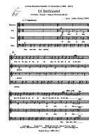
When machining the part using the CNC machine tool, first prepare the program, then operate the CNC machine by using the program. (1) First, prepare the program from a part drawing to operate the CNC machine tool. How to prepare the program is described in the Part II, “Programming.” (2) The program is to be read into the CNC system. Then, mount the workpieces and tools on the machine, and operate the tools according to the programming. Finally, execute the machining actually. How to operate the CNC system is described in the Part III, “Operation.” Part drawing
Part program
CNC PART II, "PROGRAMMING"
Machine Tool
PART III, "OPERATION"
Before the actual programming, make the machining plan for how to machine the part. Machining plan 1. Determination of workpieces machining range 2. Method of mounting workpieces on the machine tool 3. Machining sequence in every cutting process 4. Cutting tools and cutting conditions Decide the cutting method in every cutting process. Cutting process Cutting procedure 1. Cutting method : Rough Semi Finish 2. Cutting tools 3. Cutting conditions : Feedrate Cutting depth 4. Tool path
-6-
1 End face cutting
2 Outer diameter cutting
3 Grooving
B-64304EN-2/02
1.2
GENERAL
1.GENERAL
NOTES ON READING THIS MANUAL
CAUTION 1 The function of an CNC machine tool system depends not only on the CNC, but on the combination of the machine tool, its magnetic cabinet, the servo system, the CNC, the operator's panels, etc. It is too difficult to describe the function, programming, and operation relating to all combinations. This manual generally describes these from the stand-point of the CNC. So, for details on a particular CNC machine tool, refer to the manual issued by the machine tool builder, which should take precedence over this manual. 2 In the header field of each page of this manual, a chapter title is indicated so that the reader can reference necessary information easily. By finding a desired title first, the reader can reference necessary parts only. 3 This manual describes as many reasonable variations in equipment usage as possible. It cannot address every combination of features, options and commands that should not be attempted. If a particular combination of operations is not described, it should not be attempted.
1.3
NOTES ON VARIOUS KINDS OF DATA CAUTION Machining programs, parameters, offset data, etc. are stored in the CNC unit internal non-volatile memory. In general, these contents are not lost by the switching ON/OFF of the power. However, it is possible that a state can occur where precious data stored in the non-volatile memory has to be deleted, because of deletions from a maloperation, or by a failure restoration. In order to restore rapidly when this kind of mishap occurs, it is recommended that you create a copy of the various kinds of data beforehand.
-7-
II. PROGRAMMING
1
1.GENERAL
PROGRAMMING
B-64304EN-2/02
GENERAL
Chapter 1, "GENERAL", consists of the following sections: 1.1 TOOL FIGURE AND TOOL MOTION BY PROGRAM .................................................................11
1.1
TOOL FIGURE AND TOOL MOTION BY PROGRAM
Explanation -
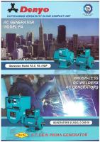
Machining using the end of cutter - Tool length compensation function
Usually, several tools are used for machining one workpiece. The tools have different tool length. It is very troublesome to change the program in accordance with the tools. Therefore, the length of each tool used should be measured in advance. By setting the difference between the length of the standard tool and the length of each tool in the CNC (See Chapter “Setting and Displaying Data” in Operator’s Manual (Common to Lathe System / Machining Center System)), machining can be performed without altering the program even when the tool is changed. This function is called tool length compensation (See Chapter, “Compensation Function” in this manual).
H1
H3
H2
H4
Standard tool
Workpiece
-
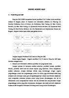
Machining using the side of cutter - Cutter compensation function Cutter path using cutter compensation Machined part figure
Workpiece
Tool
Because a cutter has a radius, the center of the cutter path goes around the workpiece with the cutter radius deviated. If radius of cutters are stored in the CNC (See Chapter “Setting and Displaying Data” in Operator’s Manual (Common to Lathe System / Machining Center System)), the tool can be moved by cutter radius apart from the machining part figure. This function is called cutter compensation (See Chapter, “Compensation Function” in this manual).
- 11 -
2. PREPARATORY FUNCTION (G FUNCTION)
2
PROGRAMMING
B-64304EN-2/02
PREPARATORY FUNCTION (G FUNCTION)
A number following address G determines the meaning of the command for the concerned block. G codes are divided into the following two types. Type One-shot G code Modal G code
Meaning The G code is effective only in the block in which it is specified. The G code is effective until another G code of the same group is specified.
(Example) G01 and G00 are modal G codes in group 01. G01 X_ ; Z_ ; G01 is effective in this range. X_ ; G00 Z_ ; G00 is effective in this range. X_ ; G01 X_ ; :
Explanation 1.
2. 3. 4. 5. 6. 7.
When the clear state (parameter CLR (No. 3402#6)) is set at power-up or reset, the modal G codes are placed in the states described below. as indicated in Table 2. (1) The modal G codes are placed in the states marked with (2) G20 and G21 remain unchanged when the clear state is set at power-up or reset. (3) Which status G22 or G23 at power on is set by parameter G23 (No. 3402#7). However, G22 and G23 remain unchanged when the clear state is set at reset. (4) The user can select G00 or G01 by setting parameter G01 (No. 3402#0). (5) The user can select G90 or G91 by setting parameter G91 (No. 3402#3). When G code system B or C is used in the lathe system, setting parameter G91 (No. 3402#3) determines which code, either G90 or G91, is effective. (6) In the machining center system, the user can select G17, G18, or G19 by setting parameters G18 and G19 (No. 3402#1 and #2). G codes in group 00 other than G10 and G11 are one-shot G codes. When a G code not listed in the G code list is specified, or a G code that has no corresponding option is specified, alarm PS0010 occurs. Multiple G codes can be specified in the same block if each G code belongs to a different group. If multiple G codes that belong to the same group are specified in the same block, only the last G code specified is valid. If a G code belonging to group 01 is specified in a canned cycle for drilling, the canned cycle for drilling is cancelled. This means that the same state set by specifying G80 is set. Note that the G codes in group 01 are not affected by a G code specifying a canned cycle for drilling. G codes are indicated by group. The group of G60 is switched according to the setting of the parameter MDL (No. 5431#0). (When the MDL bit is set to 0, the 00 group is selected. When the MDL bit is set to 1, the 01 group is selected.)
- 12 -
PROGRAMMING
B-64304EN-2/02
G code G00 G01 G02 G03 G04 G05.1 G05.4 G07.1 (G107) G09 G10 G11 G15 G16 G17 G18 G19 G20 G21 G22 G23 G27 G28 G29 G30 G31 G33 G37 G39 G40 G41 G42 G40.1 G41.1 G42.1 G43 G44 G45 G46 G47 G48 G49 G50 G51 G50.1 G51.1 G52 G53
Group 01
00
17 02 06 04
00
01 00 07
19 08
00 08 11 22 00
2.PREPARATORY FUNCTION (G FUNCTION)
Table 2 G code list Function Positioning (rapid traverse) Linear interpolation (cutting feed) Circular interpolation CW or helical interpolation CW Circular interpolation CCW or helical interpolation CCW Dwell, Exact stop AI advanced preview control / AI contour control / AI contour control II HRV3 on/off Cylindrical interpolation Exact stop Programmable data input Programmable data input mode cancel Polar coordinates command cancel Polar coordinates command Xp: X axis or its parallel axis XpYp plane selection Yp: Y axis or its parallel axis ZpXp plane selection Zp: Z axis or its parallel axis YpZp plane selection Input in inch Input in mm Stored stroke check function on Stored stroke check function off Reference position return check Automatic return to reference position Movement from reference position 2nd, 3rd and 4th reference position return Skip function Threading Automatic tool length measurement Cutter compensation : corner circular interpolation Cutter compensation : cancel Cutter compensation : left Cutter compensation : right Normal direction control cancel mode Normal direction control on : left Normal direction control on : right Tool length compensation + Tool length compensation Tool offset : increase Tool offset : decrease Tool offset : double increase Tool offset : double decrease Tool length compensation cancel Scaling cancel Scaling Programmable mirror image cancel Programmable mirror image Local coordinate system setting Machine coordinate system setting
- 13 -
2. PREPARATORY FUNCTION (G FUNCTION) G code G54 G54.1 G55 G56 G57 G58 G59 G60 G61 G62 G63 G64 G65 G66 G67 G68 G69 G73 G74 G75 G76 G77 G78 G79 G80 G80.4 G81.4 G81 G82 G83 G84 G84.2 G84.3 G85 G86 G87 G88 G89 G90 G91 G91.1 G92 G92.1 G93 G94 G95 G96 G97
Group
14
00 15 00 12 16 09 01 09 01 09 34
09
03 00
05 13
PROGRAMMING
B-64304EN-2/02
Table 2 G code list Function Workpiece coordinate system 1 selection Additional workpiece coordinate system selection Workpiece coordinate system 2 selection Workpiece coordinate system 3 selection Workpiece coordinate system 4 selection Workpiece coordinate system 5 selection Workpiece coordinate system 6 selection Single direction positioning Exact stop mode Automatic corner override Tapping mode Cutting mode Macro call Macro modal call Macro modal call cancel Coordinate system rotation mode on Coordinate system rotation mode off Peck drilling cycle Left-handed tapping cycle Plunge grinding cycle (for grinding machine) Fine boring cycle Plunge direct sizing/grinding cycle (for grinding machine) Continuous-feed surface grinding cycle (for grinding machine) Intermittent-feed surface grinding cycle (for grinding machine) Canned cycle cancel Electronic gear box : synchronization cancellation Electronic gear box : synchronization cancellation Electronic gear box : synchronization start Drilling cycle or spot boring cycle Electronic gear box : synchronization start Drilling cycle or counter boring cycle Peck drilling cycle Tapping cycle Rigid tapping cycle (FS10/11 format) Left-handed rigid tapping cycle (FS10/11 format) Boring cycle Boring cycle Back boring cycle Boring cycle Boring cycle Absolute programming Incremental programming Checking the maximum incremental amount specified Setting for workpiece coordinate system or clamp at maximum spindle speed Workpiece coordinate system preset Inverse time feed Feed per minute Feed per revolution Constant surface speed control Constant surface speed control cancel
- 14 -
PROGRAMMING
B-64304EN-2/02
G code G98 G99 G160 G161
Group 10 20
2.PREPARATORY FUNCTION (G FUNCTION)
Table 2 G code list Function Canned cycle : return to initial level Canned cycle : return to R point level In-feed control cancel (for grinding machine) In-feed control (for grinding machine)
- 15 -
3.INTERPOLATION FUNCTION
3
PROGRAMMING
B-64304EN-2/02
INTERPOLATION FUNCTION
Chapter 3, "INTERPOLATION FUNCTION", consists of the following sections: 3.1 SINGLE DIRECTION POSITIONING (G60) ...................................................................................16 3.2 THREADING (G33)...........................................................................................................................18 3.3 NANO SMOOTHING ........................................................................................................................19
3.1
SINGLE DIRECTION POSITIONING (G60)
For accurate positioning without play of the machine (backlash), final positioning from one direction is available. Overrun
Start point
Start point Temporary stop
End point
Format G60 IP_ ; IP_ : For an absolute programming, the coordinates of an end point, and for an incremental programming, the distance the tool moves.
Explanation An overrun and a positioning direction are set by the parameter No. 5440. Even when a commanded positioning direction coincides with that set by the parameter, the tool stops once before the end point. G60, which is a one-shot G-code, can be used as a modal G-code in group 01 by setting 1 to the bit 0 (MDL) of parameter No. 5431. This setting can eliminate specifying a G60 command for every block. Other specifications are the same as those for a one-shot G60 command. When a one-shot G code is specified in the single direction positioning mode, the one-shot G command is effective like G codes in group 01. (Example) When one-shot G60 commands are used. G90; G60 X0Y0; Single direction positioning G60 X100; G60 Y100; G04 X10; G00 X0Y0; When modal G60 command is used. Single direction positioning mode start G90G60; X0Y0; Single direction positioning X100; Y100;
- 16 -
PROGRAMMING
B-64304EN-2/02
G04X10; G00X0 Y0;
-
3.INTERPOLATION FUNCTION
Single direction positioning mode cancel
Overview of operation •
In the case of positioning of non-linear interpolation type (bit 1 (LRP) of parameter No. 1401 = 0) As shown below, single direction positioning is performed independently along each axis. X
Overrun distance in the Z-axis direction Overrun distance in the X-axis direction
Programmed end point Z
Programmed start point
•
In the case of positioning of linear interpolation type (bit 1 (LRP) of parameter No. 1401 = 1) Positioning of interpolation type is performed until the tool once stops before or after a specified end point. Then, the tool is positioned independently along each axis until the end point is reached. X Overrun distance in the Z-axis direction
Overrun distance in the X-axis direction
Programmed end point Z
Programmed start point
Limitation • • •
• •
• •
Single direction positioning is not performed along an axis for which no overrun distance is set in parameter No. 5440. Single direction positioning is not performed along an axis for which travel distance 0 is specified. The mirror image function is not applied in a parameter-set direction. Even in the mirror image mode, the direction of single direction positioning remains unchanged. If positioning of linear interpolation type is used, and the state of mirror image when a single direction positioning block is looked ahead differs from the state of mirror image when the execution of the block is started, an alarm is issued. When switching mirror image in the middle of a program, disable looking ahead by specifying a non-buffering M code. Then, switch mirror image when there is no look-ahead block. In the cylindrical interpolation mode (G07.1), single direction positioning cannot be used. When specifying single direction positioning on a machine that uses arbitrary angular axis control, first position the angular axis then specify the positioning of the Cartesian axis. If the reverse specification order is used, or the angular axis and Cartesian axis are specified in the same block, an incorrect positioning direction can result. In positioning at a restart position by program restart function, single direction positioning is not performed. During canned cycle for drilling, no single direction positioning is effected in drilling axis. - 17 -
3.INTERPOLATION FUNCTION •
PROGRAMMING
B-64304EN-2/02
The single direction positioning does not apply to the shift motion in the canned cycles of G76 and G87.
3.2
THREADING (G33)
Straight threads with a constant lead can be cut. The position coder mounted on the spindle reads the spindle speed in real-time. The read spindle speed is converted to the feedrate per minute to feed the tool.
Format Z
G33IP_ F_ ; F : Long axis direction lead
Workpiece X
Explanation In general, threading is repeated along the same tool path in rough cutting through finish cutting for a screw. Since threading starts when the position coder mounted on the spindle outputs a 1-turn signal, threading is started at a fixed point and the tool path on the workpiece is unchanged for repeated threading. Note that the spindle speed must remain constant from rough cutting through finish cutting. If not, incorrect thread lead will occur. In general, the lag of the servo system, etc. will produce somewhat incorrect leads at the starting and ending points of a thread cut. To compensate for this, a threading length somewhat longer than required should be specified. Table 3.2 (a) lists the ranges for specifying the thread lead. Table 3.2 (a) Ranges of lead sizes that can be specified Least command increment Command value range of the lead Metric input Inch input
0.001 mm 0.0001 mm 0.0001 inch 0.00001 inch
F1 to F50000 (0.01 to 500.00mm) F1 to F50000 (0.01 to 500.00mm) F1 to F99999 (0.0001 to 9.9999inch) F1 to F99999 (0.0001 to 9.9999inch)
- 18 -
PROGRAMMING
B-64304EN-2/02
3.INTERPOLATION FUNCTION
NOTE 1 The spindle speed is limited as follows : 1 ≤ spindle speed ≤ (Maximum feedrate) / (Thread lead) Spindle speed : min-1 Thread lead : mm or inch Maximum feedrate : mm/min or inch/min ; maximum command-specified feedrate for feed-per-minute mode or maximum feedrate that is determined based on mechanical restrictions including those related to motors, whichever is smaller 2 Cutting feedrate override is not applied to the converted feedrate in all machining process from rough cutting to finish cutting. The feedrate is fixed at 100% 3 The converted feedrate is limited by the upper feedrate specified. 4 Feed hold is disabled during threading. Pressing the feed hold key during threading causes the machine to stop at the end point of the next block after threading (that is, after the G33 mode is terminated)
Example Threading at a pitch of 1.5mm G33 Z10. F1.5;
3.3
NANO SMOOTHING
Overview When a desired sculptured surface is approximated by minute segments, the Nano smoothing function generates a smooth curve inferred from the programmed segments and performs necessary interpolation. The Nano smoothing function infers a curve from a programmed figure approximated with segments within tolerance. The interpolation of the curve reduces the segment approximation error, and the nano-interpolation makes the cutting surface smoother. The interpolation of the curve reduces the segment approximation error, and the nano interpolation makes the cutting surface smoother. For this function, the AI contour control II option is required.
Format G5.1 Q3 Xp0 Yp0 Zp0 ; G5.1 Q0 ;
: Nano smoothing mode on : Nano smoothing mode off
Xp : X-axis or an axis parallel to the X-axis Yp : Y-axis or an axis parallel to the Y-axis Zp : Z-axis or an axis parallel to the Z-axis
NOTE 1 Specify G5.1 alone in a block. (Avoid specifying any other G code in the same block.) 2 Specify position 0 for the axis programmed in the Nano smoothing mode on block. The specified axis is subjected to Nano smoothing, but no movement is made even in the absolute programming mode. (Axis moving is not performed in the G05.1Q3 block.) 3 Nano smoothing mode is also turned off at a reset. In the G5.1 Q3 block, specify the axis subject to Nano smoothing. Note that up to three axes can be subject to the Nano smoothing command at a time and that only the following axes can be specified. - 19 -
3.INTERPOLATION FUNCTION
PROGRAMMING
B-64304EN-2/02
• Basic three axes (X,Y,Z) • Axes parallel to the basic three axes If specifying the machining condition selecting function, specify G5.1 Q1 Rx first and then Nano smoothing. Example O0010 … (G5.1 Q1 R1;) G5.1 Q3 X0 Y0 Z0; … G5.1 Q0; … M30;
If the following functions are required before nano smoothing, specify G5.1. - AI contour control II - Machining condition selecting function
Nano smoothing mode off AI contour control II mode off
Explanation Generally, a program approximates a sculptured surface with minute segments with a tolerance of about 10 μm. Tolerance
Programmed point Desired curve
Fig. 3.3 (a)
Many programmed points are placed on the boundary of tolerance. The programmed points also have a rounding error owing to the least input increment of the CNC. The Nano smoothing function creates multiple insertion points between adjacent programmed points so that a smooth curve can be created from the approximation segments. The desired curve is inferred from the insertion points of multiple blocks including buffered blocks. Many insertion points are closer to the desired curve than the programmed points. A stable curve can be inferred with the insertion points created from multiple blocks including buffered blocks. Because the position of each insertion point is corrected in a unit smaller than the least input increment of the CNC within tolerance, the impact of rounding error is reduced. Nano-interpolation is performed for the curve inferred from the corrected insertion points, so the resultant cutting surface becomes smooth.
- 20 -
3.INTERPOLATION FUNCTION
PROGRAMMING
B-64304EN-2/02
Tolerance
Programmed point Insertion point Inferred curve
Corrected insertion point
Fig. 3.3 (b)
-
Specifying the tolerance
The tolerance of the program of Nano smoothing is specified in parameter No. 19581. The insertion points are corrected within tolerance, and a curve is inferred accordingly. If 0 is specified in parameter No. 19581, the minimum travel distance in the increment system is considered to be the tolerance.
-
Making a decision on the basis of the spacing between adjacent programmed points
If the spacing between adjacent programmed points (block length) exceeds the value specified in parameter No. 8486 or falls below the value specified in parameter No. 8490 in the Nano smoothing mode, the Nano smoothing mode is cancelled at the start point of the block. Linear interpolation can be performed in the block. When a decision is made on the basis of the spacing between adjacent programmed points, only the basic three axes (or their parallel axes) are considered, and the rotation axes are excluded. When the Nano smoothing mode is canceled in a block, Nano smoothing for the rotation axes is not performed, either. If the values specified in the parameters are 0, no decision is made on the basis of the spacing between adjacent programmed points.
-
Making a decision at a corner
If the difference in angle (see the Fig. 3.3 (c)) between adjacent programmed blocks exceeds the value specified in parameter No. 8487 in the Nano smoothing mode, the Nano smoothing mode is cancelled at the corner. The decision at the corner is made by considering the basic three axes (or their parallel axes) only; the rotation axes are not considered. When the Nano smoothing mode is canceled in a block, Nano smoothing for the rotation axes is not performed, either. θ1: θ2:
Difference in angle between blocks N1 and N2 Difference in angle between blocks N2 and N3
θ2 N3
N2 N1
θ1 Fig. 3.3 (c)
If the value specified in the parameter is 0, no decision is made at the corner on the basis of the difference in angle. Very minute blocks created for some reasons such as a calculation error of CAM can be ignored, and a smooth connection can be made at a corner. To do this, specify parameter No. 19582 to the minimum travel distance with which a decision is made on the basis of difference in angle. Then, the decision at a corner is disabled for a block of which distance is less than the specified minimum travel distance. - 21 -
3.INTERPOLATION FUNCTION
PROGRAMMING
B-64304EN-2/02
However, a decision based on the spacing between adjacent programmed points specified in parameter No. 8490 has higher priority than the decision at a corner. Therefore, the value specified in parameter No. 19582 must be greater than the value specified in parameter No. 8490.
If parameter No. 19582 is specified, a very minute block is not considered to be a corner, and a smooth connection can be made.
Fig. 3.3 (d)
-
Automatically turning on and off AI contour control II with Nano smoothing
Specifying G5.1 Q3 also enables Nano smoothing and AI contour control II to be turned on at the same time. The automatic velocity control by AI contour control II reduces impacts on the mechanical system. Specifying G5.1 Q0 cancels the Nano smoothing and the AI contour control II mode at the same time.
-
Conditions for enabling Nano smoothing
Nano smoothing is enabled if the conditions below are satisfied. In a block that does not satisfy the conditions for enabling it, Nano smoothing is canceled, and it is judged in the next block whether to perform Nano smoothing anew. In the following description, "block length" and "angle difference between blocks" apply to the basic three axes (or axes parallel to them) only, not rotation axes. Note, however, that in a block in which nano smoothing mode is canceled due to any of these conditions, nano smoothing on rotation axes will not be performed, either. (1) The specified block length is less than parameter No. 8486. (2) The specified block length is greater than parameter No. 8490. (3) The angle difference between the specified blocks is less than parameter No. 8487. (4) The mode is one of the following: • Linear interpolation • Feed per minute • Tool radius compensation cancel • Canned cycle cancel • Scaling cancel • Macro modal call cancel • Constant surface speed control cancel • Cutting mode • Coordinate system rotation cancel • Polar coordinate command cancel • Normal direction control cancel • Programmable mirror image cancel (5) The block does not contain a one shot G code command. (6) The block does not suppress look ahead (buffering). (7) The block contains a move command for only an axis subject to nano smoothing.
-
Checking the nano smoothing
Diagnostic data (No. 5000) indicates whether the nano smoothing mode is enabled in the current block. If the nano smoothing mode is enabled, "smoothing on" bit is set to 1.
- 22 -
PROGRAMMING
B-64304EN-2/02
3.INTERPOLATION FUNCTION
Limitation -
Modal G codes usable when Nano smoothing is specified
In a modal G code state listed below, Nano smoothing can be specified. Do not specify smooth interpolation in modal states other than these. G15 G40 G40.1 G49,G43,G44 G50 G50.1 G64 G67 G69 G80 G94 G97
-
: : : : : : : : : : : :
Polar coordinate command cancel Tool radius compensation cancel Normal direction control cancel Tool length compensation cancel or tool length compensation Scaling cancel Programmable mirror image cancel Cutting mode cancel Macro modal call cancel Coordinate system rotation/3-dimensional coordinate system conversion cancel Canned cycle cancel Feed per minute Constant surface speed control cancel
Single-block operation
When single-block operation is carried out in the Nano smoothing mode, the operation stops at a corrected insertion point not at a programmed point. Even in the Nano smoothing mode, normal single-block operation is carried out for a block that does not satisfy the conditions of Nano smoothing mode.
-
Tool length compensation
To carry out tool length compensation, specify the command before specifying Nano smoothing. Avoid changing the amount of compensation in the Nano smoothing mode. If G43, G44, or G49 is specified in a block between the block in which the command of Nano smoothing mode on (G5.1 Q3) is specified and the block in which the command of Nano smoothing mode off (G5.1 Q0) is specified, an alarm PS0343 will be issued.
-
Tool radius/tool nose radius compensation
If tool radius/tool nose radius compensation is specified in the Nano smoothing mode, the Nano smoothing mode is cancelled. Then, when the command of tool radius/tool nose radius compensation cancel (G40) is specified, a decision is made whether to start Nano smoothing from the next block. The startup and cancel operations of type C are always carried out for the tool radius/tool nose radius compensation specified in the Nano smoothing mode, irrespective of the parameter setting. A command related to tool radius/tool nose radius compensation should not be specified in the Nano smoothing mode unless it is absolutely necessary.
-
Interruption type custom macro
No interruption type custom macro can be used in the Nano smoothing mode. If the Nano smoothing mode is specified while an interruption type custom macro is enabled or if an interruption type custom macro is enabled in the Nano smoothing mode, an alarm PS0342 will be issued.
-
Manual intervention
Manual intervention by specifying the manual absolute on command cannot be performed in the Nano smoothing mode. If this is attempted, an alarm PS0340 will be issued at the cycle start after manual intervention.
- 23 -
3.INTERPOLATION FUNCTION -
PROGRAMMING
B-64304EN-2/02
Number of blocks that can be specified successively
Up to about 300,000,000 blocks can be specified successively in the Nano smoothing mode. If more blocks are specified, an alarm PS0341 will be issued. However, when a block which does not satisfy the conditions of the Nano smoothing mode is encountered, the mode is canceled and the counted number of successive blocks is reset to 0.
-
Continuity of a program
Curve interpolation is carried out for multiple programmed blocks including buffered blocks in the Nano smoothing mode. Therefore, the programmed commands must be executed continuously in the Nano smoothing mode. The continuity of a program may be lost, and continuous execution may not be performed, in some cases such as the following: A single-block stop is made in the Nano smoothing mode; and another program is executed in the MDI mode. If this occurs, an alarm PS0344 will be issued.
-
Restrictions on resumption of automatic operation
(1) Resuming a program Curve interpolation is performed for corrected insertion points not for programmed points in the Nano smoothing mode. Accordingly, when a sequence number is specified to resume the program, the operation cannot be resumed from a programmed point in a block. To resume a program, specify a block number, using the block counter displayed in the program screen. (2) Retracing (Retrace) Retracing cannot be performed in the Nano smoothing mode. (3) Manual handle retrace In Nano smoothing mode, manual handle retrace cannot be performed.
-
Dynamic graphic display
The dynamic graphic display function draws the path in the Nano smoothing mode by linear interpolation.
- 24 -
PROGRAMMING
B-64304EN-2/02
4
4.COORDINATE VALUE AND DIMENSION
COORDINATE VALUE AND DIMENSION
Chapter 4, "COORDINATE VALUE AND DIMENSION", consists of the following sections: 4.1 POLAR COORDINATE COMMAND (G15, G16) ...........................................................................25
4.1
POLAR COORDINATE COMMAND (G15, G16)
The end point coordinate value can be input in polar coordinates (radius and angle). The plus direction of the angle is counterclockwise of the selected plane first axis + direction, and the minus direction is clockwise. Both radius and angle can be commanded in either absolute or incremental programming (G90, G91).
Format Gxx Gyy G16; G00 IP_ ; : : G15; G16 G15 Gxx Gyy
IP_
-
Starting the polar coordinate command (polar coordinate mode) Polar coordinate command Canceling the polar coordinate command (polar coordinate mode)
: : : :
Polar coordinate command Polar coordinate command cancel Plane selection of the polar coordinate command (G17, G18 or G19) Center selection of the polar coordinate command (G90 or G91) G90 specifies the origin of the workpiece coordinate system as the origin of the polar coordinate system, from which a radius is measured. G91 specifies the current position as the origin of the polar coordinate system, from which a radius is measured. : Specifying the addresses of axes constituting the plane selected for the polar coordinate system, and their values First axis : radius of polar coordinate Second axis : angle of polar coordinate
Setting the origin of the workpiece coordinate system as the origin of the polar coordinate system
Specify the radius (the distance between the origin and the point) to be programmed with an absolute programming. The origin of the workpiece coordinate system is set as the origin of the polar coordinate system. When a local coordinate system (G52) is used, the origin of the local coordinate system becomes the center of the polar coordinates. Command position Command position
Radius
Radius Angle
Angle
Actual position
When the angle is specified with an absolute command
Actual position
When the angle is specified with an incremental command
- 25 -
4. COORDINATE VALUE AND DIMENSION -
PROGRAMMING
B-64304EN-2/02
Setting the current position as the origin of the polar coordinate system
Specify the radius (the distance between the current position and the point) to be programmed with an incremental programming. The current position is set as the origin of the polar coordinate system. Command position
Command position
Angle Radius
Radius Angle
Actual position
Actual position
When the angle is specified with an incremental command
When the angle is specified with an absolute command
Example Bolt hole circle Y - The origin of the workpiece coordinate system is set as the origin of the polar coordinate system. - The XY plane is selected. 150° 30° 270°
X
100mm
-
Specifying angles and a radius with absolute programmings
N1 G17 G90 G16 ;
Specifying the polar coordinate command and selecting the XY plane Setting the origin of the workpiece coordinate system as the origin of the polar coordinate system N2 G81 X100.0 Y30.0 Z-20.0 R-5.0 F200.0 ; Specifying a distance of 100 mm and an angle of 30 degrees N3 Y150.0 ; Specifying a distance of 100 mm and an angle of 150 degrees N4 Y270.0 ; Specifying a distance of 100 mm and an angle of 270 degrees N5 G15 G80 ; Canceling the polar coordinate command
-
Specifying angles with incremental programmings and a radius with absolute programmings
N1 G17 G90 G16;
Specifying the polar coordinate command and selecting the XY plane Setting the origin of the workpiece coordinate system as the origin of the polar coordinate system N2 G81 X100.0 Y30.0 Z-20.0 R-5.0 F200.0 ; Specifying a distance of 100 mm and an angle of 30 degrees N3 G91 Y120.0 ; Specifying a distance of 100 mm and an angle of +120 degrees N4 Y120.0 ; Specifying a distance of 100 mm and an angle of +120 degrees N5 G15 G80 ; Canceling the polar coordinate command
Limitation -
Specifying a radius in the polar coordinate mode
In the polar coordinate mode, specify a radius for circular interpolation or helical interpolation (G02, G03) with R. - 26 -
B-64304EN-2/02
-
PROGRAMMING
4.COORDINATE VALUE AND DIMENSION
Axes that are not considered part of a polar coordinate command in the polar coordinate mode
Axes specified for the following commands are not considered part of the polar coordinate command: • Dwell (G04) • Programmable data input (G10) • Local coordinate system setting (G52) • Workpiece coordinate system setting (G92) • Machine coordinate system setting (G53) • Stored stroke check (G22) • Coordinate system rotation (G68) • Scaling (G51)
-
Optional chamfering and corner R
Optional chamfering and corner R cannot be specified in polar coordinate mode.
- 27 -
5. FUNCTIONS TO SIMPLIFY PROGRAMMING
5
PROGRAMMING
B-64304EN-2/02
FUNCTIONS TO SIMPLIFY PROGRAMMING
Chapter 5, "FUNCTIONS TO SIMPLIFY PROGRAMMING", consists of the following sections: 5.1 5.2 5.3 5.4 5.5 5.6
CANNED CYCLE FOR DRILLING .................................................................................................28 RIGID TAPPING................................................................................................................................62 OPTIONAL CHAMFERING AND CORNER R ...............................................................................75 INDEX TABLE INDEXING FUNCTION.........................................................................................79 IN-FEED CONTROL (FOR GRINDING MACHINE)......................................................................81 CANNED GRINDING CYCLE (FOR GRINDING MACHINE)......................................................83
5.1
CANNED CYCLE FOR DRILLING
Overview Canned cycles for drilling make it easier for the programmer to create programs. With a canned cycle, a frequently-used machining operation can be specified in a single block with a G function; without canned cycles, normally more than one block is required. In addition, the use of canned cycles can shorten the program to save memory. Table 5.1 (a) lists canned cycles for drilling.
G code
Drilling (-Z direction)
G73
Intermittent feed
G74
Feed
G76 G80
Feed -
G81
Feed
G82
Feed
G83
Intermittent feed
G84
Feed
G85 G86 G87
Feed Feed Feed
G88
Feed
G89
Feed
Table 5.1 (a) Canned cycles for drilling Operation at the bottom Retraction of a hole (+Z direction) -
Rapid traverse
Dwell → Spindle CW Oriented spindle stop -
Feed Rapid traverse Rapid traverse
Dwell
Rapid traverse -
Rapid traverse
Dwell → Spindle CCW
Feed -
Feed Rapid traverse Rapid traverse
Spindle stop Spindle CW Dwell → Spindle stop Dwell
High-speed peck drilling cycle Left-hand tapping cycle Fine boring cycle Cancel Drilling cycle, spot drilling cycle Drilling cycle, counter boring cycle Peck drilling cycle Tapping cycle Boring cycle Boring cycle Back boring cycle
Manual
Boring cycle
Feed
Boring cycle
Explanation A canned cycle for drilling consists of a sequence of six operations. Operation 1 .............. Positioning of axes X and Y (including also another axis) Operation 2 .............. Rapid traverse up to point R level Operation 3 .............. Hole machining Operation 4 .............. Operation at the bottom of a hole Operation 5................ Retraction to point R level Operation 6................ Rapid traverse up to the initial point
- 28 -
Application
5.FUNCTIONS TO SIMPLIFY PROGRAMMING
PROGRAMMING
B-64304EN-2/02
Operation 1 Initial level Operation 2
Operation 6
Point R level Operation 5 Operation 3
Operation 4
Fig. 5.1 (a)
-
Rapid traverse Feed
Operation sequence of canned cycle for drilling
Positioning plane
The positioning plane is determined by plane selection code G17, G18, or G19. The positioning axis is an axis other than the drilling axis.
-
Drilling axis
Although canned cycles for drilling include tapping and boring cycles as well as drilling cycles, in this chapter, only the term drilling will be used to refer to operations implemented with canned cycles. The drilling axis is a basic axis (X, Y, or Z) not used to define the positioning plane, or any axis parallel to that basic axis. The axis (basic axis or parallel axis) used as the drilling axis is determined according to the axis address for the drilling axis specified in the same block as G codes G73 to G89. If no axis address is specified for the drilling axis, the basic axis is assumed to be the drilling axis. Table 5.1 (b) G code G17 G18 G19
Positioning plane and drilling axis Positioning plane Xp-Yp plane Zp-Xp plane Yp-Zp plane
Drilling axis Zp Yp Xp
Xp: X axis or an axis parallel to the X axis Yp: Y axis or an axis parallel to the Y axis Zp: Z axis or an axis parallel to the Z axis
Example Assume that the U, V and W axes be parallel to the X, Y, and Z axes respectively. This condition is specified by parameter No. 1022. G17 G81 Z_ _ : The Z axis is used for drilling. G17 G81 W_ _ : The W axis is used for drilling. G18 G81 Y_ _ : The Y axis is used for drilling. G18 G81 V_ _ : The V axis is used for drilling. G19 G81 X_ _ : The X axis is used for drilling. G19 G81 U_ _ : The U axis is used for drilling. G17 to G19 may be specified in a block in which any of G73 to G89 is not specified.
- 29 -
5. FUNCTIONS TO SIMPLIFY PROGRAMMING
PROGRAMMING
B-64304EN-2/02
CAUTION Switch the drilling axis after canceling a canned cycle for drilling. NOTE A parameter FXY (No. 5101 #0) can be set to the Z axis always used as the drilling axis. When FXY=0, the Z axis is always the drilling axis. -
Travel distance along the drilling axis G90/G91
The travel distance along the drilling axis varies for G90 and G91 as follows: G90 (Absolute programming)
G91 (Incremental programming)
R
R
Point R
Z=0
Z
Point Z
Fig. 5.1 (b)
-
Point R Z
Point Z
Absolute programming and incremental programming
Drilling mode
G73, G74, G76, and G81 to G89 are modal G codes and remain in effect until canceled. When in effect, the current state is the drilling mode. Once drilling data is specified in the drilling mode, the data is retained until modified or canceled. Specify all necessary drilling data at the beginning of canned cycles; when canned cycles are being performed, specify data modifications only.
-
Return point level G98/G99
When the tool reaches the bottom of a hole, the tool may be returned to point R or to the initial level. These operations are specified with G98 and G99. The following illustrates how the tool moves when G98 or G99 is specified. Generally, G99 is used for the first drilling operation and G98 is used for the last drilling operation. The initial level does not change even when drilling is performed in the G99 mode. G98 (Return to initial level)
G99 (Return to point R level)
Initial level
Point R level
Fig. 5.1 (c)
Initial level and point R level
- 30 -
PROGRAMMING
B-64304EN-2/02
-
5.FUNCTIONS TO SIMPLIFY PROGRAMMING
Repeat
To repeat drilling for equally-spaced holes, specify the number of repeats in K_. K is effective only within the block where it is specified. Specify the first hole position in incremental programming (G91). If it is specified in absolute programming (G90), drilling is repeated at the same position. Number of repeats K
The maximum command value = 9999
If K0 is specified, drilling data is stored, but drilling is not performed.
NOTE For K, specify an integer of 0 or 1 to 9999. -
Single block
If a drilling cycle is performed in a single block, the control unit stops at each of the end points of operations 1, 2, and 6 in Figure 5.1 (a). This means that three starts are made to make a single hole. At the end points of operations 1 and 2, the feed hold lamp turns on and the control unit stops. If the repetitive count is not exhausted at the end point of operation 6, the control unit stops in the feed hold mode, and otherwise, stops in the single block stop mode. Note that G87 does not cause a stop at point R in G87. G88 causes a stop at point Z after a dwell.
-
Cancel
To cancel a canned cycle, use G80 or a group 01 G code. Group 01 G codes G00 : Positioning (rapid traverse) G01 : Linear interpolation G02 : Circular interpolation or helical interpolation (CW) G03 : Circular interpolation or helical interpolation (CCW) G60 : Single directional positioning (if bit 0 (MDL) of parameter No. 5431 is "1")
-
Symbols in figures+
Subsequent sections explain the individual canned cycles. following symbols:
OSS
P
Positioning (rapid traverse G00) Cutting feed (linear interpolation G01) Manual feed Oriented spindle stop (The spindle stops at a fixed rotation position) Shift (rapid traverse G00) Dwell
- 31 -
Figures in these Explanation use the
5. FUNCTIONS TO SIMPLIFY PROGRAMMING
5.1.1
PROGRAMMING
B-64304EN-2/02
High-Speed Peck Drilling Cycle (G73)
This cycle performs high-speed peck drilling. hole while removing chips from the hole.
It performs intermittent cutting feed to the bottom of a
Format G73 X_ Y_ Z_ R_ Q_ F_ K_ ; X_ Y_ Z_ R_ Q_ F_ K_
: : : : : :
Hole position data The distance from point R to the bottom of the hole The distance from the initial level to point R level Depth of cut for each cutting feed Cutting feedrate Number of repeats (if required) G73 (G98)
G73 (G99)
Initial level
Point R
Point R
q
q
q
q
d
q
d
q Point Z
Point R level
d
d
Point Z
Explanation -
Operations
The high-speed peck drilling cycle performs intermittent feeding along the Z-axis. When this cycle is used, chips can be removed from the hole easily, and a smaller value can be set for retraction. This allows, drilling to be performed efficiently. Set the clearance, d, in parameter 5114. The tool is retracted in rapid traverse.
-
Spindle rotation
Before specifying G73, rotate the spindle using an auxiliary function (M code).
-
Auxiliary function
When the G73 code and an M code are specified in the same block, the M code is executed at the time of the first positioning operation. When K is used to specify the number of repeats, the M code is executed for the first hole only; for the second and subsequent holes, the M code is not executed.
-
Tool length compensation
When a tool length compensation (G43, G44, or G49) is specified in the canned cycle for drilling, the offset is applied after the time of positioning to point R. - 32 -
B-64304EN-2/02
PROGRAMMING
5.FUNCTIONS TO SIMPLIFY PROGRAMMING
Limitation -
Axis switching
Before the drilling axis can be changed, the canned cycle for drilling must be canceled.
-
Drilling
In a block that does not contain X, Y, Z, R, or any other axes, drilling is not performed.
-
Q
Specify Q in blocks that perform drilling. If they are specified in a block that does not perform drilling, they cannot be stored as modal data.
-
Cancel
Do not specify a G code of the 01 group (G00 to G03) and G73 in a single block. Otherwise, G73 will be canceled.
-
Tool offset
In the canned cycle mode for drilling, tool offsets are ignored.
Example M3 S2000 ; G90 G99 G73 X300. Y-250. Z-150. R-100. Q15. F120. ; Y-550. ; Y-750. ; X1000. ; Y-550. ; G98 Y-750. ; G80 G28 G91 X0 Y0 Z0 ; M5 ;
- 33 -
Cause the spindle to start rotating. Position, drill hole 1, then return to point R. Position, drill hole 2, then return to point R. Position, drill hole 3, then return to point R. Position, drill hole 4, then return to point R. Position, drill hole 5, then return to point R. Position, drill hole 6, then return to the initial level. Return to the reference position Cause the spindle to stop rotating.
5. FUNCTIONS TO SIMPLIFY PROGRAMMING
5.1.2
PROGRAMMING
B-64304EN-2/02
Left-Handed Tapping Cycle (G74)
This cycle performs left-handed tapping. In the left-handed tapping cycle, when the bottom of the hole has been reached, the spindle rotates clockwise.
Format G74 X_ Y_ Z_ R_ P_ Q_ F_ K_ ; X_ Y_ Z_ R_ P_ Q_ F_ K_
: : : : : : :
Hole position data The distance from point R to the bottom of the hole The distance from the initial level to point R level Dwell time Depth of cut for each cutting feed (bit 6 (PCT) of parameter No. 5104 = "1") Cutting feedrate Number of repeats (if required) G74 (G98)
G74 (G99)
Initial level
Point R
P
P
Spindle CCW
Point R
Point Z
P
Spindle CW
Spindle CCW P Point R level
Point Z Spindle CW
Explanation -
Operations
Tapping is performed by turning the spindle counterclockwise. When the bottom of the hole has been reached, the spindle is rotated clockwise for retraction. This creates a reverse thread.
CAUTION Feedrate overrides are ignored during left-handed tapping. A feed hold does not stop the machine until the return operation is completed. -
Spindle rotation Before specifying G74, use an auxiliary function (M code) to rotate the spindle counterclockwise. If drilling is continuously performed with a small value specified for the distance between the hole position and point R level or between the initial level and point R level, the normal spindle speed may not be reached at the start of hole cutting operation. In this case, insert a dwell before each drilling operation with G04 to delay the operation, without specifying the number of repeats for K. For some machines, the above note may not be considered. Refer to the manual provided by the machine tool builder.
-
Q command
After setting bit 6 (PCT) of parameter No. 5104 to 1, add address Q to the ordinary tapping cycle command format and specify the depth of cut for each tapping. In the peck tapping cycle, the tool is retracted to point R for each tapping. In the high-speed peck tapping cycle, the tool is retracted by the retraction distance specified for parameter No. 5213 in advance. Which operation is to be performed can be selected by setting bit 5 (PCP) of parameter No. 5200. - 34 -
PROGRAMMING
B-64304EN-2/02
5.FUNCTIONS TO SIMPLIFY PROGRAMMING
Operation First, ordinary tapping cycle operation is explained as basic operation. Before specifying a tapping cycle, rotate the spindle using an auxiliary function. 1. When a command to position the tool to a hole position, positioning is performed. 2. When point R is specified, positioning to point R is performed. 3. Tapping is performed to the bottom of the hole in cutting feed. 4. When a dwell time (P) is specified, the tool dwells. 5. Auxiliary function M05 (spindle stop) is output and the machine enters the FIN wait state. 6. When FIN is returned, auxiliary function M04 (reverse spindle rotation) is output and the machine enters the FIN wait state. 7. When FIN is returned, the tap is removed until point R is reached in cutting feed. 8. When a dwell time (P) is specified, the tool dwells. 9. Auxiliary function M05 (spindle stop) is output and the machine enters the FIN wait state. 10. When FIN is returned, auxiliary function M03 (forward spindle rotation) is output, and the machine enters the FIN wait state. 11. When FIN is returned, the tool returns to the initial point in rapid traverse when return to the initial level is specified. When the repetitive count is specified, operation is repeated from step 1. Tapping Positioning to a hole Positioning to point R
Positioning to the next hole Positioning to the initial point Point R level
Dwell Tapping to the bottom of the hole
Output of auxiliary function M05 Output of auxiliary function M03
Return to point R
Dwell
Hole bottom level
Output of auxiliary function M05 Workpiece
Output of auxiliary function M04
Peck tapping cycle When bit 6 (PCT) of parameter No. 5104 is set to 1 and bit 5 (PCP) of parameter No. 5200 is set to 1, the peck tapping cycle is used. Step 3 of the tapping cycle operation described above changes as follows: 3-1. The tool cuts the workpiece by the depth of cut q specified by address Q. 3-2. Auxiliary function M05 (spindle stop) is output, and the machine enters the FIN wait state. 3-3. When FIN is returned, auxiliary function M04 (reverse spindle rotation) is output, and the machine enters the FIN wait state. 3-4. When FIN is returned, the tool is retracted to point R in cutting feed. 3-5. Auxiliary function M05 (spindle stop) is output, and the machine enters the FIN wait state. - 35 -
5. FUNCTIONS TO SIMPLIFY PROGRAMMING
PROGRAMMING
B-64304EN-2/02
3-6. When FIN is returned, auxiliary function M03 (forward spindle rotation) is output, and the machine enters the FIN wait state. 3-7. When FIN is returned, the tool moves to the position the clearance d (parameter No. 5213) apart from the previous cutting point in cutting feed (approach). 3-1. The tool cuts the workpiece by the clearance d (parameter No. 5213) + depth of cut q (specified by address Q). Tapping is performed to the bottom of the hole by repeating the above steps. When a dwell time (P) is specified, the tool dwells only when it reaches at the bottom of the hole and reaches point R last. q:
Depth of cut
Output of auxiliary function M05
d:
Clearance
Output of auxiliary function M03 Approach
Tapping
q
Point R level
Retraction
d Tapping
Retraction Approach
q d
Tapping
q
Output of auxiliary function M05 Output of auxiliary function M04 Repeated until the bottom of the hole is reached. Workpiece Hole bottom level
High-speed peck tapping cycle When bit 6 (PCT) of parameter No. 5104 is set to 1 and bit 5 (PCP) of parameter No. 5200 is set to 0, the high-speed peck tapping cycle is used. Step 3 of the tapping cycle operation described above changes as follows: 3-1. The tool cuts the workpiece by the depth of cut q specified by address Q. 3-2. Auxiliary function M05 (spindle stop) is output, and the machine enters the FIN wait state. 3-3. When FIN is returned, auxiliary function M04 (reverse spindle rotation) is output, and the machine enters the FIN wait state. 3-4. When FIN is returned, the tool is retracted by the retraction distance d specified by parameter No. 5213 in cutting feed. 3-5. Auxiliary function M05 (spindle stop) is output, and the machine enters the FIN wait state. 3-6. When FIN is returned, auxiliary function M03 (forward spindle rotation) is output, and the machine enters the FIN wait state. 3-1. When FIN is returned, the tool cuts the workpiece by the retraction distance d (parameter No. 5213) + depth of cut q (specified by address Q). - 36 -
PROGRAMMING
B-64304EN-2/02
5.FUNCTIONS TO SIMPLIFY PROGRAMMING
Tapping is performed to the bottom of the hole by repeating the above steps. When a dwell time (P) is specified, the tool dwells only when it reaches at the bottom of the hole and reaches point R.
q:
Depth of cut
d:
Retraction distance Point R level
Tapping
q
Output of auxiliary function M05
d
Output of auxiliary function M03
Retraction
Tapping
q
d
Retraction
Tapping
q
Output of auxiliary function M05 Output of auxiliary function M04 Repeated until the bottom of the hole is reached. Workpiece Hole bottom level
Notes 1.
The depth of cut specified by address Q is stored as a modal value until the canned cycle mode is canceled. In both examples 1 and 2 below, address Q is not specified in the N20 block, but the peck tapping cycle is performed because the value specified by address Q is valid as a modal value. If this operation is not suitable, specify G80 to cancel the canned cycle mode as shown in N15 in example 3 or specify Q0 in the tapping block as shown in N20 in example 4. Example 1 N10 G84 X100. Y150. Z-100. Q20. ; N20 X150. Y200 ; ← The peck tapping cycle is also performed in this block. N30 G80 ; Example 2 N10 G83 X100. Y150. Z-100. Q20. ; N20 G84 Z-100. ; ← The peck tapping cycle is also performed in this block. N30 G80 ; Example 3 N10 G83 X100. Y150. Z-100. Q20. ; N15 G80 ; ← The canned cycle mode is canceled. N20 G84 Z-100. ; N30 G80 ; - 37 -
5. FUNCTIONS TO SIMPLIFY PROGRAMMING
PROGRAMMING
B-64304EN-2/02
Example 4 N10 G83 X100. Y150. Z-100. Q20. ; N20 G84 Z-100. Q0 ; ←Q0 is added. N30 G80 ; 2.
The unit for the reference axis that is set by parameter No. 1031, not the unit for the drilling axis is used as the unit of Q. Any sign is ignored.
-
Auxiliary function
When the G74 command and an M code are specified in the same block, the M code is executed at the time of the first positioning operation. When K is used to specify the number of repeats, the M code is executed for the first hole only; for the second and subsequent holes, the M code is not executed.
-
Tool length compensation
When a tool length compensation (G43, G44, or G49) is specified in the canned cycle for drilling, the offset is applied after the time of positioning to point R.
Limitation -
Axis switching
Before the drilling axis can be changed, the canned cycle for drilling must be canceled.
-
Drilling
In a block that does not contain X, Y, Z, R, or any other axes, drilling is not performed.
-
P
Specify P in blocks that perform drilling. If it is specified in a block that does not perform drilling, it cannot be stored as modal data.
-
Cancel
Do not specify a G code of the 01 group (G00 to G03) and G74 in a single block. Otherwise, G74 will be canceled.
-
Tool offset
In the canned cycle mode for drilling, tool offsets are ignored.
Example M4 S100 ; G90 G99 G74 X300. Y-250. Z-150. R-120. F120. ; Y-550. ; Y-750. ; X1000. ; Y-550. ; G98 Y-750. ; G80 G28 G91 X0 Y0 Z0 ; M5 ;
Cause the spindle to start rotating. Position, tapping hole 1, then return to point R. Position, tapping hole 2, then return to point R. Position, tapping hole 3, then return to point R. Position, tapping hole 4, then return to point R. Position, tapping hole 5, then return to point R. Position, tapping hole 6, then return to the initial level. Return to the reference position Cause the spindle to stop rotating.
- 38 -
PROGRAMMING
B-64304EN-2/02
5.1.3
5.FUNCTIONS TO SIMPLIFY PROGRAMMING
Fine Boring Cycle (G76)
The fine boring cycle bores a hole precisely. When the bottom of the hole has been reached, the spindle stops, and the tool is moved away from the machined surface of the workpiece and retracted.
Format G76 X_ Y_ Z_ R_ Q_ P_ F_ K_ ; X_ Y_ Z_ R_ Q_ P_ F_ K_
: : : : : : :
Hole position data The distance from point R to the bottom of the hole The distance from the initial level to point R level Shift amount at the bottom of a hole Dwell time at the bottom of a hole Cutting feedrate Number of repeats (if required) G76 (G98)
G76 (G99)
Spindle CW Initial level
Spindle orientation Tool
Spindle CW Point R
P OSS
Point R level
Point R
q
Point Z
P OSS
q
Point Z
Shift amount q
Explanation -
Operations
When the bottom of the hole has been reached, the spindle is stopped at the fixed rotation position, and the tool is moved in the direction opposite to the tool nose and retracted. This ensures that the machined surface is not damaged and enables precise and efficient boring to be performed.
-
Spindle rotation
Before specifying G76, use a Auxiliary function (M code) to rotate the spindle.
-
Auxiliary function
When the G76 command and an M code are specified in the same block, the M code is executed at the time of the first positioning operation. When K is used to specify the number of repeats, the M code is executed for the first hole only; for the second and subsequent holes, the M code is not executed.
-
Tool length compensation
When a tool length compensation (G43, G44, or G49) is specified in the canned cycle for drilling, the offset is applied after the time of positioning to point R.
Limitation -
Axis switching
Before the drilling axis can be changed, the canned cycle for drilling must be canceled.
- 39 -
5. FUNCTIONS TO SIMPLIFY PROGRAMMING -
PROGRAMMING
B-64304EN-2/02
Drilling
In a block that does not contain X, Y, Z, R, or any additional axes, drilling is not performed.
-
P/Q
Be sure to specify a positive value in Q. If Q is specified with a negative value, the sign is ignored. Set the direction of shift in the parameter (No.5148). Specify P and Q in a block that performs drilling. If they are specified in a block that does not perform drilling, they are not stored as modal data.
CAUTION Q (shift at the bottom of a hole) is a modal value retained within canned cycles for drilling. It must be specified carefully because it is also used as the depth of cut for G73 and G83. -
Cancel
Do not specify a G code of the 01 group (G00 to G03) and G76 in a single block. Otherwise, G76 will be canceled.
-
Tool offset
In the canned cycle mode for drilling, tool offsets are ignored.
Example M3 S500 ; G90 G99 G76 X300. Y-250. Z-150. R-120. Q5. P1000 F120. ; Y-550. ; Y-750. ; X1000. ; Y-550. ; G98 Y-750. ; G80 G28 G91 X0 Y0 Z0 ; M5 ;
Cause the spindle to start rotating. Position, bore hole 1, then return to point R. Orient at the bottom of the hole, then shift by 5 mm. Stop at the bottom of the hole for 1 s. Position, drill hole 2, then return to point R. Position, drill hole 3, then return to point R. Position, drill hole 4, then return to point R. Position, drill hole 5, then return to point R. Position, drill hole 6, then return to the initial level. Return to the reference position Cause the spindle to stop rotating.
- 40 -
PROGRAMMING
B-64304EN-2/02
5.1.4
5.FUNCTIONS TO SIMPLIFY PROGRAMMING
Drilling Cycle, Spot Drilling (G81)
This cycle is used for normal drilling. Cutting feed is performed to the bottom of the hole. The tool is then retracted from the bottom of the hole in rapid traverse.
Format G81 X_ Y_ Z_ R_ F_ K_ ; X_ Y_ Z_ R_ F_ K_
: : : : :
Hole position data The distance from point R to the bottom of the hole The distance from the initial level to point R level Cutting feedrate Number of repeats (if required) G81 (G98)
G81 (G99)
Initial level
Point R
Point R
Point Z
Point R level
Point Z
Explanation -
Operations
After positioning along the X- and Y-axes, rapid traverse is performed to point R. Drilling is performed from point R to point Z. The tool is then retracted in rapid traverse.
-
Spindle rotation
Before specifying G81, use an auxiliary function (M code) to rotate the spindle.
-
Auxiliary function
When the G81 command and an M code are specified in the same block, the M code is executed at the time of the first positioning operation. When K is used to specify the number of repeats, the M code is performed for the first hole only; for the second and subsequent holes, the M code is not executed.
-
Tool length compensation
When a tool length compensation (G43, G44, or G49) is specified in the canned cycle for drilling, the offset is applied after the time of positioning to point R.
Limitation -
Axis switching
Before the drilling axis can be changed, the canned cycle for drilling must be canceled.
-
Drilling
In a block that does not contain X, Y, Z, R, or any other axes, drilling is not performed.
- 41 -
5. FUNCTIONS TO SIMPLIFY PROGRAMMING -
PROGRAMMING
B-64304EN-2/02
Cancel
Do not specify a G code of the 01 group (G00 to G03) and G81 in a single block. Otherwise, G81 will be canceled.
-
Tool offset
In the canned cycle mode for drilling, tool offsets are ignored.
Example M3 S2000 ; G90 G99 G81 X300. Y-250. Z-150. R-100. F120. ; Y-550. ; Y-750. ; X1000. ; Y-550. ; G98 Y-750. ; G80 G28 G91 X0 Y0 Z0 ; M5 ;
5.1.5
Cause the spindle to start rotating. Position, drill hole 1, then return to point R. Position, drill hole 2, then return to point R. Position, drill hole 3, then return to point R. Position, drill hole 4, then return to point R. Position, drill hole 5, then return to point R. Position, drill hole 6, then return to the initial level. Return to the reference position Cause the spindle to stop rotating.
Drilling Cycle Counter Boring Cycle (G82)
This cycle is used for normal drilling. Cutting feed is performed to the bottom of the hole. At the bottom, a dwell is performed, then the tool is retracted in rapid traverse. This cycle is used to drill holes more accurately with respect to depth.
Format G82 X_ Y_ Z_ R_ P_ F_ K_ ; X_ Y_ Z_ R_ P_ F_ K_
: : : : : :
Hole position data The distance from point R to the bottom of the hole The distance from the initial level to point R level Dwell time at the bottom of a hole Cutting feed rate Number of repeats (if required) G82 (G98)
G82 (G99)
Initial level
Point R
P
Point R
Point Z
P
Point R level
Point Z
Explanation -
Operations
After positioning along the X- and Y-axes, rapid traverse is performed to point R. Drilling is then performed from point R to point Z. When the bottom of the hole has been reached, a dwell is performed. The tool is then retracted in rapid traverse. - 42 -
B-64304EN-2/02
-
PROGRAMMING
5.FUNCTIONS TO SIMPLIFY PROGRAMMING
Spindle rotation
Before specifying G82, use an auxiliary function (M code) to rotate the spindle.
-
Auxiliary function
When the G82 command and an M code are specified in the same block, the M code is executed at the time of the first positioning operation. When K is used to specify the number of repeats, the M code is executed for the first hole only; for the second and subsequent holes, the M code is not executed.
-
Tool length compensation
When a tool length compensation (G43, G44, or G49) is specified in the canned cycle for drilling, the offset is applied after the time of positioning to point R.
Limitation -
Axis switching
Before the drilling axis can be changed, the canned cycle for drilling must be canceled.
-
Drilling
In a block that does not contain X, Y, Z, R, or any other axes, drilling is not performed.
-
P
Specify P in blocks that perform drilling. If it is specified in a block that does not perform drilling, it cannot be stored as modal data.
-
Cancel
Do not specify a G code of the 01 group (G00 to G03) and G82 in a single block. Otherwise, G82 will be canceled.
-
Tool offset
In the canned cycle mode for drilling, tool offsets are ignored.
Example M3 S2000 ; Cause the spindle to start rotating. G90 G99 G82 X300. Y-250. Z-150. R-100. P1000 F120. ; Position, drill hole 1, and dwell for 1 s at the bottom of the hole, then return to point R. Y-550. ; Position, drill hole 2, then return to point R. Y-750. ; Position, drill hole 3, then return to point R. X1000. ; Position, drill hole 4, then return to point R. Y-550. ; Position, drill hole 5, then return to point R. G98 Y-750. ; Position, drill hole 6, then return to the initial level. G80 G28 G91 X0 Y0 Z0 ; Return to the reference position M5 ; Cause the spindle to stop rotating.
- 43 -
5. FUNCTIONS TO SIMPLIFY PROGRAMMING
5.1.6
PROGRAMMING
B-64304EN-2/02
Peck Drilling Cycle (G83)
This cycle performs peck drilling. It performs intermittent cutting feed to the bottom of a hole while removing shavings from the hole.
Format G83 X_ Y_ Z_ R_ Q_ F_ K_ ; X_ Y_ Z_ R_ Q_ F_ K_
: : : : : :
Hole position data The distance from point R to the bottom of the hole The distance from the initial level to point R level Depth of cut for each cutting feed Cutting feedrate Number of repeats (if required) G83 (G98)
G83 (G99)
Initial level
Point R
Point R
q
q
d
d
q
q
d q
Point R level
q
Point Z
d Point Z
Explanation -
Operations
Q represents the depth of cut for each cutting feed. It must always be specified as an incremental value. In the second and subsequent cutting feeds, rapid traverse is performed up to a d point just before where the last drilling ended, and cutting feed is performed again. d is set in parameter (No.5115). Be sure to specify a positive value in Q. Negative values are ignored.
-
Spindle rotation
Before specifying G83, use an auxiliary function (M code) to rotate the spindle.
-
Auxiliary function
When the G83 command and an M code are specified in the same block, the M code is executed at the time of the first positioning operation. When K is used to specify the number of repeats, the M code is executed for the first hole only; for the second and subsequent holes, the M code is not executed.
-
Tool length compensation
When a tool length compensation (G43, G44, or G49) is specified in the canned cycle for drilling, the offset is applied after the time of positioning to point R.
Limitation -
Axis switching
Before the drilling axis can be changed, the canned cycle for drilling must be canceled.
- 44 -
B-64304EN-2/02
-
PROGRAMMING
5.FUNCTIONS TO SIMPLIFY PROGRAMMING
Drilling
In a block that does not contain X, Y, Z, R, or any other axes, drilling is not performed.
-
Q
Specify Q in blocks that perform drilling. If they are specified in a block that does not perform drilling, they cannot be stored as modal data.
-
Cancel
Do not specify a G code of the 01 group (G00 to G03) and G83 in a single block. Otherwise, G83 will be canceled.
-
Tool offset
In the canned cycle mode for drilling, tool offsets are ignored.
Example M3 S2000 ; G90 G99 G83 X300. Y-250. Z-150. R-100. Q15. F120. ; Y-550. ; Y-750. ; X1000. ; Y-550. ; G98 Y-750. ; G80 G28 G91 X0 Y0 Z0 ; M5 ;
- 45 -
Cause the spindle to start rotating. Position, drill hole 1, then return to point R. Position, drill hole 2, then return to point R. Position, drill hole 3, then return to point R. Position, drill hole 4, then return to point R. Position, drill hole 5, then return to point R. Position, drill hole 6, then return to the initial level. Return to the reference position Cause the spindle to stop rotating.
5. FUNCTIONS TO SIMPLIFY PROGRAMMING
5.1.7
PROGRAMMING
B-64304EN-2/02
Small-Hole Peck Drilling Cycle (G83)
An arbor with the overload torque detection function is used to retract the tool when the overload torque detection signal (skip signal) is detected during drilling. Drilling is resumed after the spindle speed and cutting feedrate are changed. These steps are repeated in this peck drilling cycle. The mode for the small–hole peck drilling cycle is selected when the M code in parameter 5163 is specified. The cycle can be started by specifying G83 in this mode. This mode is canceled when G80 is specified or when a reset occurs.
NOTE When using the small-hole peck drilling cycle, set bit 4 (SPK) of parameter No. 8132 to "1".
Format G83 X_ Y_ Z_ R_ Q_ F_ I_ K_ P_ ; X_ Y_ Z_ R_ Q_ F_ I_ K_ P_
: : : : : :
Hole position data Distance from point R to the bottom of the hole Distance from the initial level to point R Depth of each cut Cutting feedrate Forward or backward traveling speed (same format as F above) (If this is omitted, the values in parameters No.5172 and No.5173 are assumed as defaults.) : Number of times the operation is repeated (if required) : Dwell time at the bottom of the hole (If this is omitted, P0 is assumed as the default.) G83 (G98)
G83 (G99)
Initial level Point R
Point R
Point R level
q
q
Δ
Δ
Δ
Δ
Overload torque
Overload torque
Point Z
Dwell
Dwell Δ:
q:
(
Point Z
Initial clearance when the tool is retracted to point R and the clearance from the bottom of the hole in the second or subsequent drilling (parameter 5174) Depth of each cut Path along which the tool travels at the rapid traverse rate Path along which the tool travels at the programmed cutting feedrate Path along which the tool travels at the forward or backward rate during the cycle specified with parameters )
- 46 -
PROGRAMMING
B-64304EN-2/02
5.FUNCTIONS TO SIMPLIFY PROGRAMMING
Explanations -
Component operations of the cycle * * *
Repeated until point Z is reached
* *
X- and Y-axis positioning Positioning at point R along the Z-axis Cutting along the Z-axis (first time, depth of cut Q, incremental) Retracting (bottom of hole → minimum clearance ∆, incremental) Retraction (bottom of hole +Δ → to point R, absolute) Forwarding (point R → to point with hole bottom + clearance ∆, absolute) Cutting (second and subsequent times, cut of depth Q + ∆, incremental) Dwell Return to point R along the Z-axis (or initial point) = end of cycle
Acceleration/deceleration during advancing and retraction is controlled according to the cutting feed acceleration/deceleration time constant. When retraction is performed, the position is checked at point R.
-
Specifying an M code
When the M code in parameter 5163 is specified, the system enters the mode for the small–hole peck drilling cycle. This M code does not wait for FIN. Care must be taken when this M code is specified with another M code in the same block. (Example) M03 M ; → Waits for FIN. M M03 ; → Does not wait for FIN.
-
Specifying a G code
When G83 is specified in the mode for the small-hole peck drilling cycle, the cycle is started. This continuous–state G code remains unchanged until another canned cycle is specified or until the G code for canceling the canned cycle is specified. This eliminates the need for specifying drilling data in each block when identical drilling is repeated.
-
Signal indicating that the cycle is in progress
In this cycle, the signal indicating that the small–hole peck drilling cycle is in progress is output after the tool is positioned at the hole position along the axes not used for drilling. Signal output continues during positioning to point R along the drilling axis and terminates upon a return to point R or the initial level. For details, refer to the manual of the machine tool builder.
-
Overload torque detection signal
A skip signal is used as the overload torque detection signal. The skip signal is effective while the tool is advancing or drilling and the tool tip is between points R and Z. (The signal causes a retraction). For details, refer to the manual of the machine tool builder.
NOTE When receiving overload torque detect signal while the tool is advancing, the tool will be retracted (clearance Δ and to the point R), then advanced to the same target point as previous advancing.
-
Changing the drilling conditions
In a single G83 cycle, drilling conditions are changed for each drilling operation (advance → drilling → retraction). Bits 1 and 2 of parameter OLS, NOL No. 5160 can be specified to suppress the change in drilling conditions.
- 47 -
5. FUNCTIONS TO SIMPLIFY PROGRAMMING 1
PROGRAMMING
B-64304EN-2/02
Changing the cutting feedrate The cutting feedrate programmed with the F code is changed for each of the second and subsequent drilling operations. In parameters No.5166 and No.5167, specify the respective rates of change applied when the skip signal is detected and when it is not detected in the previous drilling operation. Cutting feedrate = F × α
α=1.0 α=α×β÷100, where β is the rate of change for each drilling operation When the skip signal is detected during the previous drilling operation: β=b1% (parameter No.5166) When the skip signal is not detected during the previous drilling operation: β=b2% (parameter No.5167) If the rate of change in cutting feedrate becomes smaller than the rate specified in parameter 5168, the cutting feedrate is not changed. The cutting feedrate can be increased up to the maximum cutting feedrate. 2
Changing the spindle speed The spindle speed programmed with the S code is changed for each of the second and subsequent advances. In parameters 5164 and 5165, specify the rates of change applied when the skip signal is detected and when it is not detected in the previous drilling operation. Spindle speed = S × γ
γ=1.0 γ=γ×δ÷100, where δ is the rate of change for each drilling operation When the skip signal is detected during the previous drilling operation: δ=d1% (parameter No.5164) When the skip signal is not detected during the previous drilling operation: δ=d2% (parameter No.5165) When the cutting feedrate reaches the minimum rate, the spindle speed is not changed. The spindle speed can be increased up to a value corresponding to the maximum value of S analog data.
-
Advance and retraction
Advancing and retraction of the tool are not executed in the same manner as rapid-traverse positioning. Like cutting feed, the two operations are carried out as interpolated operations. Note that the tool life management function excludes advancing and retraction from the calculation of the tool life.
-
Specifying address I
The forward or backward traveling speed can be specified with address I in the same format as address F, as shown below: G83 I1000 ; (without decimal point) G83 I1000. ; (with decimal point) Both commands indicate a speed of 1000 mm/min. Address I specified with G83 in the continuous-state mode continues to be valid until G80 is specified or until a reset occurs.
- 48 -
B-64304EN-2/02
PROGRAMMING
5.FUNCTIONS TO SIMPLIFY PROGRAMMING
NOTE If address I is not specified and parameter No.5172 (for backward) or No.5173 (for forward) is set to 0, the forward or backward travel speed is same as the cutting feedrate specified by F.
-
Functions that can be specified
In this canned cycle mode, the following functions can be specified: • Hole position on the X-axis, Y-axis, and additional axis • Operation and branch by custom macro • Subprogram (hole position group, etc.) calling • Switching between absolute and incremental modes • Coordinate system rotation • Scaling (This command will not affect depth of cut Q or small clearance Δ.) • Dry run • Feed hold
-
Single block
When single-block operation is enabled, drilling is stopped after each retraction. Also, a single block stop is performed by setting parameter SBC (No.5105 bit 0)
-
Feedrate override
The feedrate override function works during cutting, retraction, and advancing in the cycle.
-
Custom macro interface
The number of retractions made during cutting and the number of retractions made in response to the overload signal received during cutting can be output to custom macro common variables (#100 to #149) specified in parameters No.5170 and No.5171. Parameters No.5170 and No.5171 can specify variable numbers within the range of #100 to #149. Parameter No.5170: Specifies the number of the common variable to which the number of retractions made during cutting is output. Parameter No.5171: Specifies the number of the common variable to which the number of retractions made in response to the overload signal received during cutting is output.
NOTE The numbers of retraction output to common variables are cleared by G83 while small-hole peck drilling cycle mode.
Limitation -
Subprogram call
In the canned cycle mode, specify the subprogram call command M98P_ in an independent block.
Example M03 S_ ; M ; G83 X_ Y_ Z_ R_ Q_ F_ I_ K_ P_ ; X_ Y_ ; : : G80 ;
Cause the spindle to start rotating. Specifies the small-hole peck drilling cycle mode. Specifies the small-hole peck drilling cycle. Drills at another position. Cancels the small-hole peck drilling cycle mode.
- 49 -
5. FUNCTIONS TO SIMPLIFY PROGRAMMING
5.1.8
PROGRAMMING
B-64304EN-2/02
Tapping Cycle (G84)
This cycle performs tapping. In this tapping cycle, when the bottom of the hole has been reached, the spindle is rotated in the reverse direction.
Format G84 X_ Y_ Z_ R_ P_ Q_ F_ K_ ; X_ Y_ Z_ R_ P_ Q_ F_ K_
: : : : : : :
Hole position data The distance from point R to the bottom of the hole The distance from the initial level to point R level Dwell time Depth of cut for each cutting feed (bit 6 (PCT) of parameter No. 5104 = "1") Cutting feedrate Number of repents (if required) G84 (G98)
G84 (G99)
Initial level
Spindle CW Point R
P
Point R
P
P
Point Z
Spindle CW P Point R level
Point Z Spindle CCW
Spindle CCW
Explanation -
Operations
Tapping is performed by rotating the spindle clockwise. When the bottom of the hole has been reached, the spindle is rotated in the reverse direction for retraction. This operation creates threads.
CAUTION Feedrate overrides are ignored during tapping. A feed hold does not stop the machine until the return operation is completed. -
Spindle rotation
Before specifying G84, use an auxiliary function (M code) to rotate the spindle. If drilling is continuously performed with a small value specified for the distance between the hole position and point R level or between the initial level and point R level, the normal spindle speed may not be reached at the start of hole cutting operation. In this case, insert a dwell before each drilling operation with G04 to delay the operation, without specifying the number of repeats for K. For some machines, the above note may not be considered. Refer to the manual provided by the machine tool builder.
-
Q command
See “Left-Handed Tapping Cycle (G74)” above.
- 50 -
B-64304EN-2/02
-
PROGRAMMING
5.FUNCTIONS TO SIMPLIFY PROGRAMMING
Auxiliary function
When the G84 command and an M code are specified in the same block, the M code is executed at the time of the first positioning operation. When the K is used to specify number of repeats, the M code is executed for the first hole only; for the second and subsequent holes, the M code is not executed.
-
Tool length compensation
When a tool length compensation (G43, G44, or G49) is specified in the canned cycle for drilling, the offset is applied after the time of positioning to point R.
Limitation -
Axis switching
Before the drilling axis can be changed, the canned cycle for drilling must be canceled.
-
Drilling
In a block that does not contain X, Y, Z, R, or any other axes, drilling is not performed.
-
P
Specify P in blocks that perform drilling. If it is specified in a block that does not perform drilling, it cannot be stored as modal data.
-
Cancel
Do not specify a G code of the 01 group (G00 to G03) and G84 in a single block. Otherwise, G84 will be canceled.
Example M3 S100 ; G90 G99 G84 X300. Y-250. Z-150. R-120. P300 F120. ; Y-550. ; Y-750. ; X1000. ; Y-550. ; G98 Y-750. ; G80 G28 G91 X0 Y0 Z0 ; M5 ;
- 51 -
Cause the spindle to start rotating. Position, drill hole 1, then return to point R. Position, drill hole 2, then return to point R. Position, drill hole 3, then return to point R. Position, drill hole 4, then return to point R. Position, drill hole 5, then return to point R. Position, drill hole 6, then return to the initial level. Return to the reference position Cause the spindle to stop rotating.
5. FUNCTIONS TO SIMPLIFY PROGRAMMING
5.1.9
PROGRAMMING
B-64304EN-2/02
Boring Cycle (G85)
This cycle is used to bore a hole.
Format G85 X_ Y_ Z_ R_ F_ K_ ; X_ Y_ Z_ R_ F_ K_
: : : : :
Hole position data The distance from point R to the bottom of the hole The distance from the initial level to point R level Cutting feed rate Number of repeats (if required) G85 (G98)
G85 (G99)
Initial level
Point R
Point R
Point Z
Point R level
Point Z
Explanation -
Operations
After positioning along the X- and Y- axes, rapid traverse is performed to point R. Drilling is performed from point R to point Z. When point Z has been reached, cutting feed is performed to return to point R.
-
Spindle rotation
Before specifying G85, use an auxiliary function (M code) to rotate the spindle.
-
Auxiliary function
When the G85 command and an M code are specified in the same block, the M code is executed at the time of the first positioning operation. When K is used to specify the number of repeats, the M code is executed for the first hole only; for the second and subsequent holes, the M code is not executed.
-
Tool length compensation
When a tool length compensation (G43, G44, or G49) is specified in the canned cycle for drilling, the offset is applied after the time of positioning to point R.
Limitation -
Axis switching
Before the drilling axis can be changed, the canned cycle for drilling must be canceled.
-
Drilling
In a block that does not contain X, Y, Z, R, or any other axes, drilling is not performed.
-
Cancel
Do not specify a G code of the 01 group (G00 to G03) and G85 in a single block. Otherwise, G85 will be canceled. - 52 -
PROGRAMMING
B-64304EN-2/02
-
5.FUNCTIONS TO SIMPLIFY PROGRAMMING
Tool offset
In the canned cycle mode for drilling, tool offsets are ignored.
Example M3 S100 ; G90 G99 G85 X300. Y-250. Z-150. R-120. F120. ; Y-550. ; Y-750. ; X1000. ; Y-550. ; G98 Y-750. ; G80 G28 G91 X0 Y0 Z0 ; M5 ;
5.1.10
Cause the spindle to start rotating. Position, drill hole 1, then return to point R. Position, drill hole 2, then return to point R. Position, drill hole 3, then return to point R. Position, drill hole 4, then return to point R. Position, drill hole 5, then return to point R. Position, drill hole 6, then return to the initial level. Return to the reference position Cause the spindle to stop rotating.
Boring Cycle (G86)
This cycle is used to bore a hole.
Format G86 X_ Y_ Z_ R_ F_ K_ ; X_ Y_ Z_ R_ F_ K_
: : : : :
Hole position data The distance from point R to the bottom of the hole The distance from the initial level to point R level Cutting feed rate Number of repeats (if required) G86 (G98)
G86 (G99)
Spindle CW Initial level
Spindle CW Point R
Point R
Point R level
Point Z
Point Z
Spindle stop
Spindle stop
Explanation -
Operations
After positioning along the X- and Y-axes, rapid traverse is performed to point R. Drilling is performed from point R to point Z. When the spindle is stopped at the bottom of the hole, the tool is retracted in rapid traverse.
-
Spindle rotation
Before specifying G86, use an auxiliary function (M code) to rotate the spindle.
- 53 -
5. FUNCTIONS TO SIMPLIFY PROGRAMMING
PROGRAMMING
B-64304EN-2/02
If drilling is continuously performed with a small value specified for the distance between the hole position and point R level or between the initial level and point R level, the normal spindle speed may not be reached at the start of hole cutting operation. In this case, insert a dwell before each drilling operation with G04 to delay the operation, without specifying the number of repeats for K. For some machines, the above note may not be considered. Refer to the manual provided by the machine tool builder.
-
Auxiliary function
When the G86 command and an M code are specified in the same block, the M code is executed at the time of the first positioning operation. When K is used to specify the number of repeats, the M code is executed for the first hole only; for the second and subsequent holes, the M code is not executed.
-
Tool length compensation
When a tool length compensation (G43, G44, or G49) is specified in the canned cycle for drilling, the offset is applied after the time of positioning to point R.
Limitation -
Axis switching
Before the drilling axis can be changed, the canned cycle for drilling must be canceled.
-
Drilling
In a block that does not contain X, Y, Z, R, or any other axes, drilling is not performed.
-
Cancel
Do not specify a G code of the 01 group (G00 to G03) and G86 in a single block. Otherwise, G86 will be canceled.
-
Tool offset
In the canned cycle mode for drilling, tool offsets are ignored.
Example M3 S2000 ; G90 G99 G86 X300. Y-250. Z-150. R-100. F120. ; Y-550. ; Y-750. ; X1000. ; Y-550. ; G98 Y-750. ; G80 G28 G91 X0 Y0 Z0 ; M5 ;
Cause the spindle to start rotating. Position, drill hole 1, then return to point R. Position, drill hole 2, then return to point R. Position, drill hole 3, then return to point R. Position, drill hole 4, then return to point R. Position, drill hole 5, then return to point R. Position, drill hole 6, then return to the initial level. Return to the reference position Cause the spindle to stop rotating.
- 54 -
PROGRAMMING
B-64304EN-2/02
5.1.11
5.FUNCTIONS TO SIMPLIFY PROGRAMMING
Back Boring Cycle (G87)
This cycle performs accurate boring.
Format G87 X_ Y_ Z_ R_ Q_ P_ F_ K_ ; X_ Y_ Z_ R_ Q_ P_ F_ K_
: : : : : : :
Hole position data The distance from point R to the bottom of the hole The distance from the initial level to point R Shift amount at the bottom of a hole Dwell time at the bottom of a hole Cutting feed rate Number of repeats (if required) G87 (G98)
Spindle orientation Tool
G87 (G99)
q OSS Initial level
Spindle CW
Not used
OSS Point Z P Spindle CW
Point R
Shift amount q
Explanation After positioning along the X- and Y-axes, the spindle is stopped at the fixed rotation position. The tool is moved in the direction opposite to the tool nose, positioning (rapid traverse) is performed to the bottom of the hole (point R). The tool is then shifted in the direction of the tool nose and the spindle is rotated clockwise. Boring is performed in the positive direction along the Z-axis until point Z is reached. At point Z, the spindle is stopped at the fixed rotation position again, the tool is shifted in the direction opposite to the tool nose, then the tool is returned to the initial level. The tool is then shifted in the direction of the tool nose and the spindle is rotated clockwise to proceed to the next block operation.
-
Spindle rotation
Before specifying G87, use an auxiliary function (M code) to rotate the spindle. If drilling is continuously performed with a small value specified for the distance between the hole position and point R level or between the initial level and point R level, the normal spindle speed may not be reached at the start of hole cutting operation. In this case, insert a dwell before each drilling operation with G04 to delay the operation, without specifying the number of repeats for K. For some machines, the above note may not be considered. Refer to the manual provided by the machine tool builder.
-
Auxiliary function
When the G87 command and an M code are specified in the same block, the M code is executed at the time of the first positioning operation. When K is used to specify the number of repeats, the M code is executed for the first hole only; for the second and subsequent holes, the M code is not executed.
-
Tool length compensation
When a tool length compensation (G43, G44, or G49) is specified in the canned cycle for drilling, the offset is applied after the time of positioning to point R. - 55 -
5. FUNCTIONS TO SIMPLIFY PROGRAMMING
PROGRAMMING
B-64304EN-2/02
Limitation -
Axis switching
Before the drilling axis can be changed, the canned cycle for drilling must be canceled.
-
Drilling
In a block that does not contain X, Y, Z, R, or any additional axes, drilling is not performed.
-
P/Q
Be sure to specify a positive value in Q. If Q is specified with a negative value, the sign is ignored. Set the direction of shift in the parameter (No. 5148). Specify P and Q in a block that performs drilling. If they are specified in a block that does not perform drilling, they are not stored as modal data.
CAUTION Q (shift at the bottom of a hole) is a modal value retained in canned cycles for drilling. It must be specified carefully because it is also used as the depth of cut for G73 and G83. -
Cancel
Do not specify a G code of the 01 group (G00 to G03) and G87 in a single block. Otherwise, G87 will be canceled.
-
Tool offset
In the canned cycle mode for drilling, tool offsets are ignored.
Example M3 S500 ; G90 G87 X300. Y-250. Z-150. R-120. Q5. P1000 F120. ; Y-550. ; Y-750. ; X1000. ; Y-550. ; Y-750. ; G80 G28 G91 X0 Y0 Z0 ; M5 ;
Cause the spindle to start rotating. Position, bore hole 1. Orient at the initial level, then shift by 5 mm. Stop at point Z for 1 s. Position, drill hole 2. Position, drill hole 3. Position, drill hole 4. Position, drill hole 5. Position, drill hole 6 Return to the reference position Cause the spindle to stop rotating.
- 56 -
PROGRAMMING
B-64304EN-2/02
5.1.12
5.FUNCTIONS TO SIMPLIFY PROGRAMMING
Boring Cycle (G88)
This cycle is used to bore a hole.
Format G88 X_ Y_ Z_ R_ P_ F_ K_ ; X_ Y_ Z_ R_ P_ F_ K_
: : : : : :
Hole position data The distance from point R to the bottom of the hole The distance from the initial level to point R level Dwell time at the bottom of a hole Cutting feed rate Number of repeats (if required) G88 (G98)
G88 (G99)
Spindle CW Initial level Spindle CW Point R
Point R
Point Z
Point R level
Point Z P
P
Spindle stop after dwell
Spindle stop after dwell
Explanation -
Operations
After positioning along the X- and Y-axes, rapid traverse is performed to point R. Boring is performed from point R to point Z. When boring is completed, a dwell is performed at the bottom of the hole, then the spindle is stopped and enters the hold state. At this time, you can switch to the manual mode and move the tool manually. Any manual operations are available; it is desirable to finally retract the tool from the hole for safety, though. At the restart of machining in the DNC operation or memory mode, the tool returns to the initial level or point R level according to G98 or G99 and the spindle rotates clockwise. Then, operation is restarted according to the programmed commands in the next block.
-
Spindle rotation
Before specifying G88, use an auxiliary function (M code) to rotate the spindle.
-
Auxiliary function
When the G88 command and an M code are specified in the same block, the M code is executed at the time of the first positioning operation. When K is used to specify the number of repeats, the M code is executed for the first hole only; for the second and subsequent holes, the M code is not executed.
-
Tool length compensation
When a tool length compensation (G43, G44, or G49) is specified in the canned cycle for drilling, the offset is applied after the time of positioning to point R.
- 57 -
5. FUNCTIONS TO SIMPLIFY PROGRAMMING
PROGRAMMING
B-64304EN-2/02
Limitation -
Axis switching
Before the drilling axis can be changed, the canned cycle for drilling must be canceled.
-
Drilling
In a block that does not contain X, Y, Z, R, or any other axes, drilling is not performed.
-
P
Specify P in blocks that perform drilling. If it is specified in a block that does not perform drilling, it cannot be stored as modal data.
-
Cancel
Do not specify a G code of the 01 group (G00 to G03) and G88 in a single block. Otherwise, G88 will be canceled.
-
Tool offset
In the canned cycle mode for drilling, tool offsets are ignored.
Example M3 S2000 ; Cause the spindle to start rotating. G90 G99 G88 X300. Y-250. Z-150. R-100. P1000 F120. ; Position, drill hole 1, return to point R then stop at the bottom of the hole for 1 s. Y-550. ; Position, drill hole 2, then return to point R. Y-750. ; Position, drill hole 3, then return to point R. X1000. ; Position, drill hole 4, then return to point R. Y-550. ; Position, drill hole 5, then return to point R. G98 Y-750. ; Position, drill hole 6, then return to the initial level. G80 G28 G91 X0 Y0 Z0 ; Return to the reference position M5 ; Cause the spindle to stop rotating.
- 58 -
PROGRAMMING
B-64304EN-2/02
5.1.13
5.FUNCTIONS TO SIMPLIFY PROGRAMMING
Boring Cycle (G89)
This cycle is used to bore a hole.
Format G89 X_ Y_ Z_ R_ P_ F_ K_ ; X_ Y_ Z_ R_ P_ F_ K_
: : : : : :
Hole position data The distance from point R to the bottom of the hole The distance from the initial level to point R level Dwell time at the bottom of a hole Cutting feed rate Number of repeats (if required) G89 (G98)
G89 (G99)
Initial level
Point R
P
Point R
Point Z
P
Point R level
Point Z
Explanation -
Operations
This cycle is almost the same as G85. The difference is that this cycle performs a dwell at the bottom of the hole.
-
Spindle rotation
Before specifying G89, use an auxiliary function (M code) to rotate the spindle.
-
Auxiliary function
When the G89 command and an M code are specified in the same block, the M code is executed at the time of the first positioning operation. When K is used to specify the number of repeats, the M code is executed for the first hole only; for the second and subsequent holes, the M code is not executed.
-
Tool length compensation
When a tool length compensation (G43, G44, or G49) is specified in the canned cycle for drilling, the offset is applied after the time of positioning to point R.
Limitation -
Axis switching
Before the drilling axis can be changed, the canned cycle for drilling must be canceled.
-
Drilling
In a block that does not contain X, Y, Z, R, or any other axes, drilling is not performed.
-
P
Specify P in blocks that perform drilling. If it is specified in a block that does not perform drilling, it cannot be stored as modal data. - 59 -
5. FUNCTIONS TO SIMPLIFY PROGRAMMING -
PROGRAMMING
B-64304EN-2/02
Cancel
Do not specify a G code of the 01 group (G00 to G03) and G89 in a single block. Otherwise, G89 will be canceled.
-
Tool offset
In the canned cycle mode for drilling, tool offsets are ignored.
Example M3 S100 ; Cause the spindle to start rotating. G90 G99 G89 X300. Y-250. Z-150. R-120. P1000 F120. ; Position, drill hole 1, return to point R then stop at the bottom of the hole for 1 s. Y-550. ; Position, drill hole 2, then return to point R. Y-750. ; Position, drill hole 3, then return to point R. X1000. ; Position, drill hole 4, then return to point R. Y-550. ; Position, drill hole 5, then return to point R. G98 Y-750. ; Position, drill hole 6, then return to the initial level. G80 G28 G91 X0 Y0 Z0 ; Return to the reference position M5 ; Cause the spindle to stop rotating.
5.1.14
Canned Cycle Cancel for Drilling (G80)
G80 cancels canned cycles for drilling.
Format G80 ;
Explanation All canned cycles for drilling are canceled to perform normal operation. Point R and point Z are cleared. Other drilling data is also canceled (cleared).
Example M3 S100 ; G90 G99 G88 X300. Y-250. Z-150. R-120. F120. ; Y-550. ; Y-750. ; X1000. ; Y-550. ; G98 Y-750. ; G80 G28 G91 X0 Y0 Z0 ; M5 ;
Cause the spindle to start rotating. Position, drill hole 1, then return to point R. Position, drill hole 2, then return to point R. Position, drill hole 3, then return to point R. Position, drill hole 4, then return to point R. Position, drill hole 5, then return to point R. Position, drill hole 6, then return to the initial level. Return to the reference position, canned cycle cancel Cause the spindle to stop rotating.
- 60 -
PROGRAMMING
B-64304EN-2/02
5.1.15
5.FUNCTIONS TO SIMPLIFY PROGRAMMING
Example for Using Canned Cycles for Drilling
Offset value +200.0 is set in offset No.11, +190.0 is set in offset No.15, and +150.0 is set in offset No.31 Program example ; N001 G92 X0 Y0 Z0; N002 G90 G00 Z250.0 T11 M6; N003 G43 Z0 H11; N004 S30 M3; N005 G99 G81 X400.0 Y-350.0 Z-153.0 R-97.0 F120; N006 Y-550.0; N007 G98 Y-750.0; N008 G99 X1200.0; N009 Y-550.0; N010 G98 Y-350.0; N011 G00 X0 Y0 M5; N012 G49 Z250.0 T15 M6; N013 G43 Z0 H15; N014 S20 M3; N015 G99 G82 X550.0 Y-450.0 Z-130.0 R-97.0 P300 F70; N016 G98 Y-650.0; N017 G99 X1050.0; N018 G98 Y-450.0; N019 G00 X0 Y0 M5; N020 G49 Z250.0 T31 M6; N021 G43 Z0 H31; N022 S10 M3; N023 G85 G99 X800.0 Y-350.0 Z-153.0 R47.0 F50; N024 G91 Y-200.0 K2; N025 N026 N027
G28 X0 Y0 M5; G49 Z0; M0;
- 61 -
Coordinate setting at reference position Tool change Initial level, tool length compensation Spindle start Positioning, then #1 drilling Positioning, then #2 drilling and point R level return Positioning, then #3 drilling and initial level return Positioning, then #4 drilling and point R level return Positioning, then #5 drilling and point R level return Positioning, then #6 drilling and initial level return Reference position return, spindle stop Tool length compensation cancel, tool change Initial level, tool length compensation Spindle start Positioning, then #7 drilling, point R level return Positioning, then #8 drilling, initial level return Positioning, then #9 drilling, point R level return Positioning, then #10 drilling, initial level return Reference position return, spindle stop Tool length compensation cancel, tool change Initial level, tool length compensation Spindle start Positioning, then #11 drilling, point R level return Positioning, then #12, 13 drilling, point R level return Reference position return, spindle stop Tool length compensation cancel Program stop
5. FUNCTIONS TO SIMPLIFY PROGRAMMING
PROGRAMMING
B-64304EN-2/02
Program using tool length offset and canned cycles Reference position
350
#1 100
#11 #7 200
100
#2
100
#10 #5
#12 #8
Y
#6
#9 200
100
#3
#13
#4
X 400
150
#1 to 6 #7 to 10 #11 to 13 Z
250
250
150
Drilling of a 10 mm diameter hole Drilling of a 20 mm diameter hole Boring of a 95 mm diameter hole (depth 50 mm)
Retract position 250 Initial level X
50 50 30 20 T 11
200
Fig. 5.1.15 (a)
5.2
T 15
190
T 31
150
Example for using canned cycles for drilling
RIGID TAPPING
The tapping cycle (G84) and left-handed tapping cycle (G74) may be performed in standard mode or rigid tapping mode. In standard mode, the spindle is rotated and stopped along with a movement along the tapping axis using auxiliary functions M03 (rotating the spindle clockwise), M04 (rotating the spindle counterclockwise), and M05 (stopping the spindle) to perform tapping. In rigid mode, tapping is performed by controlling the spindle motor as if it were a servo motor and by interpolating between the tapping axis and spindle. When tapping is performed in rigid mode, the spindle rotates one turn every time a certain feed (thread lead) which takes place along the tapping axis. This operation does not vary even during acceleration or deceleration. Rigid mode eliminates the need to use a floating tap required in the standard tapping mode, thus allowing faster and more precise tapping. - 62 -
PROGRAMMING
B-64304EN-2/02
5.2.1
5.FUNCTIONS TO SIMPLIFY PROGRAMMING
Rigid Tapping (G84)
When the spindle motor is controlled in rigid mode as if it were a servo motor, a tapping cycle can be speed up.
Format G84 X_ Y_ Z_ R_ P_ F_ K_ ; X_ Y_ : Hole position data Z_ : The distance from point R to the bottom of the hole and the position of the bottom of the hole R_ : The distance from the initial level to point R level P_ : Dwell time at the bottom of the hole and at point R when a return is made F_ : Cutting feedrate K_ : Number of repeats (if required)
G84.2 X_ Y_ Z_ R_ P_ F_ L_ ; (Series 10/11 format) L_
: Number of repeats (if required) G84 (G98)
G84 (G99)
Spindle stop
Spindle stop Initial level
Operation 1 Operation 6 Spindle P stop Point R level
Operation 2 Spindle CW Point R Operation 3
Spindle CW
P Point R
Point R level
Operation 5
P Spindle stop
Spindle stop
Point Z
Operation 4
P
Spindle CCW
Spindle stop
Point Z Spindle CCW
Explanation After positioning along the X- and Y-axes, rapid traverse is performed to point R. Tapping is performed from point R to point Z. When tapping is completed, the spindle is stopped and a dwell is performed. The spindle is then rotated in the reverse direction, the tool is retracted to point R, then the spindle is stopped. Rapid traverse to initial level is then performed. While tapping is being performed, the feedrate override and spindle override are assumed to be 100%. Feedrate override can be enabled by setting, however.
-
Rigid mode
Rigid mode can be specified using any of the following methods: • Specify M29 S***** before a tapping command. • Specify M29 S***** in a block which contains a tapping command. • Specify G84 for rigid tapping (parameter G84 No. 5200 #0 set to 1).
-
Thread lead
In feed-per-minute mode, the thread lead is obtained from the expression, feedrate ÷ spindle speed. In feed-per-revolution mode, the thread lead equals the feedrate speed. - 63 -
5. FUNCTIONS TO SIMPLIFY PROGRAMMING -
PROGRAMMING
B-64304EN-2/02
Tool length compensation
If a tool length compensation (G43, G44, or G49) is specified in the canned cycle, the offset is applied at the time of positioning to point R.
-
Series 10/11 format command
Rigid tapping can be performed using Series 10/11 format commands. The rigid tapping sequence (including data transfer to and from the PMC), Limitation, and the like are the same as described in this chapter.
-
Acceleration/deceleration after interpolation
Linear or bell-shaped acceleration/deceleration can be applied.
-
Look-ahead acceleration/deceleration before interpolation
Look-ahead acceleration/deceleration before interpolation is invalid.
-
Override
Various types of override functions are invalid. The following override functions can be enabled by setting corresponding parameters: • Extraction override • Override signal See “Override during Rigid Tapping” below for details.
-
Dry run
Dry run can be executed also in G84 (G74). When dry run is executed at the feedrate for the drilling axis in G84 (G74), tapping is performed according to the feedrate. Note that the spindle speed becomes faster at a higher dry run feedrate.
-
Machine lock
Machine lock can be executed also in G84 (G74). When G84 (G74) is executed in the machine lock state, the tool does not move along the drilling axis. Therefore, the spindle does not also rotate.
-
Reset
When a reset is performed during rigid tapping, the rigid tapping mode is canceled and the spindle motor enters the normal mode. Note that the G84 (G74) mode is not canceled in this case when bit 6 (CLR) of parameter No. 3402 is set.
-
Interlock
Interlock can also be applied in G84 (G74).
-
Feed hold and single block
When bit 6 (FHD) of parameter No. 5200 is set to 0, feed hold and single block are invalid in the G84 (G74) mode. When this bit is set to 1, they are valid.
-
Backlash compensation
In the rigid tapping mode, backlash compensation is applied to compensate the lost motion when the spindle rotates clockwise or counterclockwise. Set the amount of backlash in parameters Nos. 5321 to 5324. Along the drilling axis, backlash compensation has been applied.
- 64 -
PROGRAMMING
B-64304EN-2/02
5.FUNCTIONS TO SIMPLIFY PROGRAMMING
Limitation -
Axis switching
Before the drilling axis can be changed, the canned cycle must be canceled. If the drilling axis is changed in rigid mode, alarm PS0206 is issued.
-
S command
•
If a speed higher than the maximum speed for the gear being used is specified, alarm PS0200 is issued. When the rigid tapping canned cycle is cancelled, the S command used for rigid tapping is cleared to S0.
•
-
Distribution amount for the spindle
The maximum distribution amount is as follows (displayed on diagnosis display No. 451): • For a serial spindle: 32,767 pulses per 8 ms This amount is changed according to the gear ratio setting for the position coder or rigid tapping command. If a setting is made to exceed the upper limit, alarm PS0202 is issued.
-
F command
If a value exceeding the upper limit of cutting feedrate is specified, alarm PS0011 is issued.
-
Unit of F command G94 G95
-
Metric input
Inch input
1 mm/min 0.01 mm/rev
0.01 inch/min 0.0001 inch/rev
Remarks Decimal point programming allowed Decimal point programming allowed
M29
If an S command and axis movement are specified between M29 and G84, alarm PS0203 is issued. If M29 is specified in a tapping cycle, alarm PS0204 is issued.
-
P
Specify P in a block that performs drilling. If P is specified in a non-drilling block, it is not stored as modal data.
-
Cancel
Do not specify a G code of the 01 group (G00 to G03) and G74 in a single block. Otherwise, G74 will be canceled.
-
Tool offset
In the canned cycle mode, tool offsets are ignored.
-
Program restart
A program cannot be restarted during rigid tapping.
-
Subprogram call
In the canned cycle mode, specify the subprogram call command M98P_ in an independent block.
Example Z-axis feedrate 1000 mm/min Spindle speed 1000 min-1 Thread lead 1.0 mm
G94; G00 X120.0 Y100.0 ;
Specify a feed-per-minute command. Positioning
- 65 -
5. FUNCTIONS TO SIMPLIFY PROGRAMMING M29 S1000 ; G84 Z-100.0 R-20.0 F1000 ;
PROGRAMMING
B-64304EN-2/02
Rigid mode specification Rigid tapping
G95 ; G00 X120.0 Y100.0 ; M29 S1000 ; G84 Z-100.0 R-20.0 F1.0 ;
5.2.2
Specify a feed-per-revolution command. Positioning Rigid mode specification Rigid tapping
Left-Handed Rigid Tapping Cycle (G74)
When the spindle motor is controlled in rigid mode as if it were a servo motor, tapping cycles can be speed up.
Format G74 X_ Y_ Z_ R_ P_ F_ K_ ; X_ Y_ : Hole position data Z_ : The distance from point R to the bottom of the hole and the position of the bottom of the hole R_ : The distance from the initial level to point R level P_ : Dwell time at the bottom of the hole and at point R when return is made. F_ : Cutting feedrate K_ : Number of repeats (if required)
G84.3 X_ Y_ Z_ R_ P_ F_ L_ ; (Series 10/11 format) L_
: Number of repeats (if required) G74 (G98)
G74 (G99)
Spindle stop
Spindle stop Initial level
Operation 1 Operation 2 Spindle CCW
Operation 6 Spindle P stop Point R level
Point R Operation 3
P Point R
Point R level
Operation 5
P Spindle stop
Spindle stop
Spindle CCW
Point Z
Operation 4
P
Spindle CW
Spindle stop
Point Z Spindle CW
Explanation After positioning along the X- and Y-axes, rapid traverse is performed to point R. Tapping is performed from point R to point Z. When tapping is completed, the spindle is stopped and a dwell is performed. The spindle is then rotated in the normal direction, the tool is retracted to point R, then the spindle is stopped. Rapid traverse to initial level is then performed. While tapping is being performed, the feedrate override and spindle override are assumed to be 100%. Feedrate override can be enabled by setting, however.
-
Rigid mode
Rigid mode can be specified using any of the following methods: • Specify M29 S***** before a tapping command. - 66 -
B-64304EN-2/02
PROGRAMMING
5.FUNCTIONS TO SIMPLIFY PROGRAMMING
• •
Specify M29 S***** in a block which contains a tapping command. Specify G74 for rigid tapping. (parameter G84 (No. 5200#0) set to1).
-
Thread lead
In feed-per-minute mode, the thread lead is obtained from the expression, feedrate ÷ spindle speed. In feed-per-revolution mode, the thread lead equals the feedrate.
-
Tool length compensation
If a tool length compensation (G43, G44, or G49) is specified in the canned cycle, the offset is applied at the time of positioning to point R.
-
Series 10/11 format command
Rigid tapping can be performed using Series 15 format commands. The rigid tapping sequence (including data transfer to and from the PMC), Limitation, and the like are the same as described in this chapter.
-
Acceleration/deceleration after interpolation
Linear or bell-shaped acceleration/deceleration can be applied.
-
Look-ahead acceleration/deceleration before interpolation
Look-ahead acceleration/deceleration before interpolation is invalid.
-
Override
Various types of override functions are invalid. The following override functions can be enabled by setting corresponding parameters: • Extraction override • Override signal See “Override during Rigid Tapping” below for details.
-
Dry run
Dry run can be executed also in G84 (G74). When dry run is executed at the feedrate for the drilling axis in G84 (G74), tapping is performed according to the feedrate. Note that the spindle speed becomes faster at a higher dry run feedrate.
-
Machine lock
Machine lock can be executed also in G84 (G74). When G84 (G74) is executed in the machine lock state, the tool does not move along the drilling axis. Therefore, the spindle does not also rotate.
-
Reset
When a reset is performed during rigid tapping, the rigid tapping mode is canceled and the spindle motor enters the normal mode. Note that the G84 (G74) mode is not canceled in this case when bit 6 (CLR) of parameter No. 3402 is set.
-
Interlock
Interlock can also be applied in G84 (G74).
-
Feed hold and single block
When bit 6 (FHD) of parameter No. 5200 is set to 0, feed hold and single block are invalid in the G84 (G74) mode. When this bit is set to 1, they are valid.
- 67 -
5. FUNCTIONS TO SIMPLIFY PROGRAMMING -
PROGRAMMING
B-64304EN-2/02
Backlash compensation
In the rigid tapping mode, backlash compensation is applied to compensate the lost motion when the spindle rotates clockwise or counterclockwise. Set the amount of backlash in parameters Nos. 5321 to 5324. Along the drilling axis, backlash compensation has been applied.
Limitation -
Axis switching
Before the drilling axis can be changed, the canned cycle must be canceled. If the drilling axis is changed in rigid mode, alarm PS0206 is issued.
-
S command
• •
Specifying a rotation speed exceeding the maximum speed for the gear used causes alarm PS0200. When the rigid tapping canned cycle is cancelled, the S command used for rigid tapping is cleared to S0.
-
Distribution amount for the spindle
The maximum distribution amount is as follows (displayed on diagnosis display No. 451): • For a serial spindle: 32,767 pulses per 8 ms This amount is changed according to the gear ratio setting for the position coder or rigid tapping command. If a setting is made to exceed the upper limit, alarm PS0202 is issued.
-
F command
Specifying a value that exceeds the upper limit of cutting feedrate causes alarm PS0011.
-
Unit of F command Metric input
Inch input
Remarks
1 mm/min 0.01 mm/rev
0.01 inch/min 0.0001 inch/rev
Decimal point programming allowed Decimal point programming allowed
G94 G95
-
M29
Specifying an S command or axis movement between M29 and G84 causes alarm PS0203. Then, specifying M29 in the tapping cycle causes alarm PS0204.
-
P
Specify P in a block that performs drilling. If P is specified in a non-drilling block, it is not stored as modal data.
-
Cancel
Do not specify a G code of the 01 group (G00 to G03) and G74 in a single block. Otherwise, G74 will be canceled.
-
Tool offset
In the canned cycle mode, tool offsets are ignored.
-
Subprogram call
In the canned cycle mode, specify the subprogram call command M98P_ in an independent block.
Example Z-axis feedrate 1000 mm/min Spindle speed 1000 min-1 Thread lead 1.0 mm - 68 -
PROGRAMMING
B-64304EN-2/02
G94 ; G00 X120.0 Y100.0 ; M29 S1000 ; G74 Z-100.0 R-20.0 F1000 ;
Specify a feed-per-minute command. Positioning Rigid mode specification Rigid tapping
G95 ; G00 X120.0 Y100.0 ; M29 S1000 ; G74 Z-100.0 R-20.0 F1.0 ;
Specify a feed-per-revolution command. Positioning Rigid mode specification Rigid tapping
- 69 -
5.FUNCTIONS TO SIMPLIFY PROGRAMMING
5. FUNCTIONS TO SIMPLIFY PROGRAMMING
5.2.3
PROGRAMMING
B-64304EN-2/02
Peck Rigid Tapping Cycle (G84 or G74)
Tapping a deep hole in rigid tapping mode may be difficult due to chips sticking to the tool or increased cutting resistance. In such cases, the peck rigid tapping cycle is useful. In this cycle, cutting is performed several times until the bottom of the hole is reached. Two peck tapping cycles are available: High-speed peck tapping cycle and standard peck tapping cycle. These cycles are selected using the PCP bit (bit 5) of parameter 5200.
Format G84 (or G74) X_ Y_ Z_ R_ P_ Q_ F_ K_ ; X_ Y_ : Hole position data Z_ : The distance from point R to the bottom of the hole and the position of the bottom of the hole R_ : The distance from the initial level to point R level P_ : Dwell time at the bottom of the hole and at point R when a return is made Q_ : Depth of cut for each cutting feed F_ : The cutting feedrate K_ : Number of repeats (if required)
G84.2 (or G84.3) X_ Y_ Z_ R_ P_ Q_ F_ L_ ; (Series 10/11 format) L_ : Number of repeats (if required) G84, G74 (G98) • High-speed peck tapping cycle (Parameter PCP(No.5200#5)=0) The tool operates at a normal cutting feedrate. The normal time constant is used. Retraction can be overridden. The retraction time constant is used.
G84, G74 (G99)
d = retraction distance Initial level Point R level
Point R q
q
d
q
d
q
Point R level
Point R
q
d
q
Point Z
• Peck tapping cycle (Parameter PCP(No.5200#5)=1) The tool operates at a normal cutting feedrate. The normal time constant is used. Retraction can be overridden. The retraction time constant is used. Retraction can be overridden. The normal time constant is used.
d
Point Z
d = cutting start distance Initial level Point R q
Point R level
‡
Point R q
d
q
d
q
Point R level
‡ d d
q
q
Point Z
- 70 -
Point Z
B-64304EN-2/02
PROGRAMMING
5.FUNCTIONS TO SIMPLIFY PROGRAMMING
Explanation -
High-speed peck tapping cycle
After positioning along the X- and Y-axes, rapid traverse is performed to point R. From point R, cutting is performed with depth Q (depth of cut for each cutting feed), then the tool is retracted by distance d. The DOV bit (bit 4) of parameter 5200 specifies whether retraction can be overridden or not. When point Z has been reached, the spindle is stopped, then rotated in the reverse direction for retraction. Set the retraction distance, d, in parameter 5213.
-
Peck tapping cycle
After positioning along the X- and Y-axes, rapid traverse is performed to point R level. From point R, cutting is performed with depth Q (depth of cut for each cutting feed), then a return is performed to point R. The DOV bit (bit 4) of parameter 5200 specifies whether the retraction can be overridden or not. The moving of cutting feedrate F is performed from point R to a position distance d from the end point of the last cutting, which is where cutting is restarted. For this moving of cutting feedrate F, the specification of the DOV bit (bit 4) of parameter 5200 is also valid. When point Z has been reached, the spindle is stopped, then rotated in the reverse direction for retraction. Set d (distance to the point at which cutting is started) in parameter 5213.
-
Acceleration/deceleration after interpolation
Linear or bell-shaped acceleration/deceleration can be applied.
-
Look-ahead acceleration/deceleration before interpolation
Look-ahead acceleration/deceleration before interpolation is invalid.
-
Override
Various types of override functions are invalid. The following override functions can be enabled by setting corresponding parameters: • Extraction override • Override signal See “Override during Rigid Tapping” below for details.
-
Dry run
Dry run can be executed also in G84 (G74). When dry run is executed at the feedrate for the drilling axis in G84 (G74), tapping is performed according to the feedrate. Note that the spindle speed becomes faster at a higher dry run feedrate.
-
Machine lock
Machine lock can be executed also in G84 (G74). When G84 (G74) is executed in the machine lock state, the tool does not move along the drilling axis. Therefore, the spindle does not also rotate.
-
Reset
When a reset is performed during rigid tapping, the rigid tapping mode is canceled and the spindle motor enters the normal mode. Note that the G84 (G74) mode is not canceled in this case when bit 6 (CLR) of parameter No. 3402 is set.
-
Interlock
Interlock can also be applied in G84 (G74).
-
Feed hold and single block
When bit 6 (FHD) of parameter No. 5200 is set to 0, feed hold and single block are invalid in the G84 (G74) mode. When this bit is set to 1, they are valid. - 71 -
5. FUNCTIONS TO SIMPLIFY PROGRAMMING -
PROGRAMMING
B-64304EN-2/02
Backlash compensation
In the rigid tapping mode, backlash compensation is applied to compensate the lost motion when the spindle rotates clockwise or counterclockwise. Set the amount of backlash in parameters Nos. 5321 to 5324. Along the drilling axis, backlash compensation has been applied.
Limitation -
Axis switching
Before the drilling axis can be changed, the canned cycle must be canceled. If the drilling axis is changed in rigid mode, alarm PS0206 is issued.
-
S command
• •
Specifying a rotation speed exceeding the maximum speed for the gear used causes alarm PS0200. When the rigid tapping canned cycle is cancelled, the S command used for rigid tapping is cleared to S0.
-
Distribution amount for the spindle
The maximum distribution amount is as follows (displayed on diagnosis display No. 451): • For a serial spindle: 32,767 pulses per 8 ms This amount is changed according to the gear ratio setting for the position coder or rigid tapping command. If a setting is made to exceed the upper limit, alarm PS0202 is issued.
-
F command
Specifying a value that exceeds the upper limit of cutting feedrate causes alarm PS0011.
-
Unit of F command Metric input
Inch input
Remarks
1 mm/min 0.01 mm/rev
0.01 inch/min 0.0001 inch/rev
Decimal point programming allowed Decimal point programming allowed
G94 G95
-
M29
Specifying an S command or axis movement between M29 and G84 causes alarm PS0203. Then, specifying M29 in the tapping cycle causes alarm PS0204.
-
P/Q
Specify P and Q in a block that performs drilling. If they are specified in a block that does not perform drilling, they are not stored as modal data. When Q0 is specified, the peck rigid tapping cycle is not performed.
-
Cancel
Do not specify a group 01 G code (G00 to G03) and G84 in the same block. If they are specified together, G84 is canceled.
-
Tool offset
In the canned cycle mode, tool offsets are ignored.
-
Subprogram call
In the canned cycle mode, specify the subprogram call command M98P_ in an independent block.
-
d (parameter No.5213)
Perform operation in the peck tapping cycle within point R. That is, set a value which does not exceed point R for d (parameter No. 5213). - 72 -
PROGRAMMING
B-64304EN-2/02
5.2.4
5.FUNCTIONS TO SIMPLIFY PROGRAMMING
Canned Cycle Cancel (G80)
The rigid tapping canned cycle is canceled. For how to cancel this cycle, see the Subsection 5.1.14, "Canned Cycle Cancel for Drilling (G80)."
NOTE When the rigid tapping canned cycle is cancelled, the S value used for rigid tapping is also cleared (as if S0 is specified). Accordingly, the S command specified for rigid tapping cannot be used in a subsequent part of the program after the cancellation of the rigid tapping canned cycle. After canceling the rigid tapping canned cycle, specify a new S command as required.
5.2.5
Override during Rigid Tapping
Various types of override functions are invalid. The following override functions can be enabled by setting corresponding parameters: • Extraction override • Override signal
5.2.5.1
Extraction override
For extraction override, the fixed override set in the parameter or override specified in a program can be enabled at extraction (including retraction during peck drilling/high-speed peck drilling).
Explanation -
Specifying the override in the parameter
Set bit 4 (DOV) of parameter No. 5200 to 1 and set the override in parameter No. 5211. An override from 0% to 200% in 1% steps can be set. Bit 3 (OVU) of parameter No. 5201 can be set to 1 to set an override from 0% to 2000% in 10% steps.
-
Specifying the override in a program
Set bit 4 (DOV) of parameter No. 5200 and bit 4 (OV3) of parameter No. 5201 to 1. The spindle speed at extraction can be specified in the program. Specify the spindle speed at extraction using address "J" in the block in which rigid tapping is specified. Example) To specify 1000 min-1 for S at cutting and 2000 min-1 for S at extraction . M29 S1000 ; G84 Z-100. F1000. J2000 ; . The difference in the spindle speed is converted to the actual override by the following calculation. Therefore, the spindle speed at extraction may not be the same as that specified at address "J". If the override does not fall in the range between 100% and 200%, it is assumed to be 100%. Override (%) =
Spindle speed at extraction (specified at J ) Spindle speed (specified at S )
× 100
Bit 6 (OVE) of parameter No. 5202 can be set to 1 to extend the override value to 100% to 2000%. If the specified override value is outside the range between 100% and 2000%, it is assumed to be 100%. - 73 -
5. FUNCTIONS TO SIMPLIFY PROGRAMMING
PROGRAMMING
B-64304EN-2/02
The override to be applied is determined according to the setting of parameters and that in the command as shown in the table below. When bit 6 (OVE) of parameter No. 5202 is set to 0 Parameter setting Command Within the range between 100% to 200% Outside the range between 100% to 200% No spindle speed at extraction specified at address "J" Spindle speed at extraction specified at address "J"
DOV = 1 OV3 = 1 Command in the program
OV3 = 0 Parameter No. 5211
100%
DOV = 0
100%
Parameter No. 5211
When bit 6 (OVE) of parameter No. 5202 is set to 1 Parameter setting Command Within the range between 100% to 2000% Outside the range between 100% to 2000% No spindle speed at extraction specified at address "J" Spindle speed at extraction specified at address "J"
DOV = 1 OV3 = 1 Command in the program 100%
OV3 = 0 Parameter No. 5211
DOV = 0
100%
Parameter No. 5211
NOTE 1 Do not use a decimal point in the value specified at address "J". If a decimal point is used, the value is assumed as follows: Example) When the increment system for the reference axis is IS-B • When pocket calculator type decimal point programming is not used The specified value is converted to the value for which the least input increment is considered. "J200." is assumed to be 200000 min-1. • When pocket calculator type decimal point programming is used The specified value is converted to the value obtained by rounding down to an integer. "J200." is assumed to be 200 min-1. 2 Do not use a minus sign in the value specified at address "J". If a minus sign is used, a value outside the range is assumed to be specified. 3 The maximum override is obtained using the following equation so that the spindle speed to which override at extraction is applied do not exceed the maximum used gear speed (specified in parameters Nos. 5241 to 5243). For this reason, the obtained value is not the same as the maximum spindle speed depending on the override. Maximum override (%) =
Maximum spindle speed (specified in parameters ) Spindle speed (specified at S )
× 100
4 When a value is specified at address "J" for specifying the spindle speed at extraction in the rigid tapping mode, it is valid until the canned cycle is canceled.
5.2.5.2
Override signal
By setting bit 4 (OVS) of parameter No. 5203 to 1, override can be applied to cutting/extraction operation during rigid tapping as follows: • Applying override using the feedrate override signal • Canceling override using the override cancel signal - 74 -
PROGRAMMING
B-64304EN-2/02
5.FUNCTIONS TO SIMPLIFY PROGRAMMING
There are the following relationships between this function and override to each operation: • At cutting When the override cancel signal is set to 0 Value specified by the override signal When the override cancel signal is set to 1 100% • At extraction When the override cancel signal is set to 0 Value specified by the override signal When the override cancel signal is set to 1 and extraction override is disabled 100% When the override cancel signal is set to 1 and extraction override is enabled Value specified for extraction override
NOTE 1 The maximum override is obtained using the following equation so that the spindle speed to which override is applied do not exceed the maximum used gear speed (specified in parameters Nos. 5241 to 5243). For this reason, the obtained value is not the same as the maximum spindle speed depending on the override. Maximum override (%) =
Maximum spindle speed (specified in parameters ) Spindle speed (specified at S )
× 100
2 Since override operation differs depending on the machine in use, refer to the manual provided by the machine tool builder.
5.3
OPTIONAL CHAMFERING AND CORNER R
Overview Chamfering and corner R blocks can be inserted automatically between the following: • Between linear interpolation and linear interpolation blocks • Between linear interpolation and circular interpolation blocks • Between circular interpolation and linear interpolation blocks • Between circular interpolation and circular interpolation blocks
Format , C_ , R_
Chamfering Corner R
Explanation When the above specification is added to the end of a block that specifies linear interpolation (G01) or circular interpolation (G02 or G03), a chamfering or corner R block is inserted. Blocks specifying chamfering and corner R can be specified consecutively.
- 75 -
5. FUNCTIONS TO SIMPLIFY PROGRAMMING -
PROGRAMMING
B-64304EN-2/02
Chamfering
After C, specify the distance from the hypothetical corner intersection to the start and end points. The hypothetical corner point is the corner point that would exist if chamfering were not performed.
G91 G01 X100.0 ,C10.0 ; X100.0 Y100.0 ;
Inserted chamfering block C
C Hypothetical corner intersection
-
Corner R
After R, specify the radius for corner R.
G91 G01 X100.0 ,R10.0 ; X100.0 Y100.0 ; Center of a circle with radius R
R
Example N001 G92 G90 X0 Y0 ; N002 G00 X10.0 Y10.0 ; N003 G01 X50.0 F10.0 ,C5.0 ; N004 Y25.0 ,R8.0 ; N005 G03 X80.0 Y50.0 R30.0 ,R8.0 ; N006 G01 X50.0 ,R8.0 ; N007 Y70.0 ,C5.0 ; N008 X10.0 ,C5.0 ; N009 Y10.0 ; N010 G00 X0 Y0 ; N011 M0;
- 76 -
Inserted corner R block
5.FUNCTIONS TO SIMPLIFY PROGRAMMING
PROGRAMMING
B-64304EN-2/02
Y
N008
70.0
N007
60.0
N006
50.0 40.0 N009
N005
30.0 20.0
N004
10.0 N010 N011
N003
N002
0 N001 10.0
20.0
30.0
40.0
50.0
60.0
70.0
80.0
X
Limitation -
Invalid specification
Chamfering (,C) or corner R (,R) specified in a block other than a linear interpolation (G01) or circular interpolation (G02 or G03) block is ignored.
-
Next block
A block specifying chamfering or corner R must be followed by a block that specifies a move command using linear interpolation (G01) or circular interpolation (G02 or G03). If the next block does not contain these specifications, alarm PS0051 is issued. Between these blocks, however, only one block specifying G04 (dwell) can be inserted. The dwell is executed after execution of the inserted chamfering or corner R block.
-
Exceeding the move range
If the inserted chamfering or corner R block causes the tool to go beyond the original interpolation move range, alarm PS0055 is issued. G91 G01 X30.0 ; G03 X7.5 Y16.0 R37.0 ,C28.0 ; G03 X67.0 Y-27.0 R55.0 ;
The tool path without chamfering is indicated with a solid line.
C
C
Chamfering block to be inserted
Fig 5.3 (a) Exceeding the move range
-
Plane selection
A chamfering or corner R block is inserted only for a command to move the tool within the same plane. - 77 -
5. FUNCTIONS TO SIMPLIFY PROGRAMMING
PROGRAMMING
B-64304EN-2/02
Example: When the U-axis is set as an axis parallel to the basic X-axis (by setting parameter No. 1022 to 5), the following program performs chamfering between cutting feed along the U-axis and that along the Y-axis: G17 U0 Y0 G00 U100.0 Y100.0 G01 U200.0 F100 ,C30.0 Y200.0 The following program causes alarm PS0055, however. (Because chamfering is specified in the block to move the tool along the X-axis, which is not on the selected plane) G17 U0 Y0 G00 U100.0 Y100.0 G01 X200.0 F100 ,C30.0 Y200.0 The following program also causes alarm PS0055. (Because the block next to the chamfering command moves the tool along the X-axis, which is not on the selected plane) G17 U0 Y0 G00 U100.0 Y100.0 G01 Y200.0 F100 ,C30.0 X200.0 If a plane selection command (G17, G18, or G19) is specified in the block next to the block in which chamfering or corner R is specified, alarm PS0051 is issued.
-
Travel distance 0
When two linear interpolation operations are performed, the chamfering or corner R block is regarded as having a travel distance of zero if the angle between the two straight lines is within ±1°. When linear interpolation and circular interpolation operations are performed, the corner R block is regarded as having a travel distance of zero if the angle between the straight line and the tangent to the arc at the intersection is within ±1°. When two circular interpolation operations are performed, the corner R block is regarded as having a travel distance of zero if the angle between the tangents to the arcs at the intersection is within ±1°.
-
Single block operation
When the block in which chamfering or corner R is specified is executed in the single block mode, operation continues to the end point of the inserted chamfering or corner R block and the machine stops in the feed hold mode at the end point. When bit 0 (SBC) of parameter No. 5105 is set to 1, the machine stops in the feed hold mode also at the start point of the inserted chamfering or corner R block.
-
Unusable G codes
The following G codes are unusable in the same block as for chamfering or corner R commands or with a block for chamfering or corner R inputs that define continuous figures. • G codes (except G04) in group 00 • G68 in group 16
-
Threading
If ”,C” or “,R” is specified in a threading command block, the alarm PS0050 is issued.
NOTE When ",C" and ",R" are specified in the same block, the address specified last is valid.
- 78 -
PROGRAMMING
B-64304EN-2/02
5.4
5.FUNCTIONS TO SIMPLIFY PROGRAMMING
INDEX TABLE INDEXING FUNCTION
By specifying indexing positions (angles) for the indexing axis (one rotation axis, A, B, or C), the index table of the machining center can be indexed. Before and after indexing, the index table is automatically unclamped or clamped .
NOTE To enable the index table indexing function, reset bit 0 (ITI) of parameter No. 5501 to "0" and set bit 3 (IXC) of parameter No. 8132 to "1".
Explanation -
Indexing position
Specify an indexing position with address A, B, or C (set to bit 0 of parameter ROTx No.1006). The indexing position is specified by either of the following (depending on bit 4 of parameter G90 No.5500): 1. Absolute value only (Bit 4 (G90) of parameter No.5500 =1) 2. Absolute or incremental value depending on the specified G code: G90 or G91 (Bit 4 (G90) of parameter No.5500 =0) A positive value indicates an indexing position in the counterclockwise direction. A negative value indicates an indexing position in the clockwise direction. The minimum indexing angle of the index table is the value set to parameter 5512. Only multiples of the least input increment can be specified as the indexing angle. If any value that is not a multiple is specified, an alarm PS1561 occurs. Decimal fractions can also be entered. When a decimal fraction is entered, the 1's digit corresponds to degree units. A
Value specified for rotation from A to B (case 2 described above) G90 B-45.0 ; or G91 B-105.0;
+60° 0° -45° B
-
Direction and value of rotation
The direction of rotation and angular displacement are determined by either of the following two methods. Refer to the manual written by the machine tool builder to find out which method is applied. 1. Using the auxiliary function specified in parameter No. 5511 (Address) (Indexing position) (Auxiliary function); Rotation in the negative direction (Address) (Indexing position); Rotation in the positive direction (No auxiliary functions are specified.) An angular displacement greater than 360° is rounded down to the corresponding angular displacement within 360° when bit 2 of parameter ABS No. 5500 specifies this option. For example, when G90 B400.0 (auxiliary function); is specified at a position of 0 , the table is rotated by 40° in the negative direction. 2. Using no auxiliary functions By setting to bits 2, 3, and 4 of parameter ABS, INC,G90 No.5500, operation can be selected from the following two options. Select the operation by referring to the manual written by the machine tool builder. (1) Rotating in the direction in which an angular displacement becomes shortest
- 79 -
5. FUNCTIONS TO SIMPLIFY PROGRAMMING
PROGRAMMING
B-64304EN-2/02
This is valid only in absolute programming. A specified angular displacement greater than 360° is rounded down to the corresponding angular displacement within 360° when bit 2 of parameter ABS No.5500 specifies this option. For example, when G90 B400.0; is specified at a position of 0, the table is rotated by 40° in the positive direction. (2) Rotating in the specified direction In the absolute programming, the value set in bit 2 of parameter ABS No.5500 determines whether an angular displacement greater than 360° is rounded down to the corresponding angular displacement within 360°. In the incremental programming, the angular displacement is not rounded down. For example, when G90 B720.0; is specified at a position of 0, the table is rotated twice in the positive direction, when the angular displacement is not rounded down.
-
Feedrate
The table is always rotated around the indexing axis in the rapid traverse mode. Dry runs cannot be executed for the indexing axis.
WARNING If a reset is made during indexing of the index table, a reference position return must be made before each time the index table is indexed subsequently. NOTE 1 If an index table indexing axis and another controlled axis are specified in the same block either alarm PS1564 is issued or the command is executed, depending on bit 6 (SIM) of parameter No. 5500 and bit 0 (IXS) of parameter No. 5502. 2 The waiting state which waits for completion of clamping or unclamping of the index table is indicated on diagnosis display No.12. 3 The auxiliary function specifying a negative direction is processed in the CNC. The relevant M code signal and completion signal are sent between the CNC and the machine. 4 If a reset is made while waiting for completion of clamping or unclamping, the clamp or unclamp signal is cleared and the CNC exits the completion wait state. -
Indexing function and other functions Table 5.4 (a) Item
Relative position display Absolute position display Movement in the machine coordinate system (G53) Single direction positioning 2nd auxiliary function (B code) Operations while moving the indexing axis
Index indexing function and other functions Explanation
This value is rounded down when bit 1 of parameter REL No.5500 specifies this option. This value is rounded down when bit 2 of parameter ABS No.5500 specifies this option. Impossible to move Impossible to specify Possible with any address other than B that of the indexing axis.
Unless otherwise processed by the machine, feed hold, interlock and emergency stop can be executed. Machine lock can be executed after indexing is completed. Disabled SERVO OFF signal The indexing axis is usually in the servo-off state. Incremental commands for The workpiece coordinate system and machine coordinate system must always agree indexing the index table with each other on the indexing axis (the workpiece zero point offset value is zero.).
- 80 -
5.FUNCTIONS TO SIMPLIFY PROGRAMMING
PROGRAMMING
B-64304EN-2/02
Item
Explanation
Manual operation is disabled in the JOG, INC, or HANDLE mode. Operations for indexing the A manual reference position return can be made. If the axis selection signal is set to index table zero during manual reference position return, movement is stopped and the clamp command is not executed. Pole position detection This function cannot be used on an axis on which the pole position detection function is function used.
5.5
IN-FEED CONTROL (FOR GRINDING MACHINE)
Overview Each time the switch on the machine operator's panel is input when the machine is at a table swing end point, the machine makes a cut by a constant amount along the programmed profile on the specified YZ plane. This makes it possible to perform grinding and cutting in a timely manner and facilitating the grinding of a workpiece with a profile. X=a External signal input
C •
E •
(2)
(3) A α • (1)B•(4) • D
Y X
X=0 Sensor placement
Z
For example, it is possible to machine a workpiece with a profile programmed with linear interpolation, circular interpolation, and linear interpolation on the YZ plane, such as that shown in the figure above. A sensor is placed at a X = 0 position so that the switch on the machine operator's panel is input when the sensor detects the grinding wheel. When the program is started at point A, the machine is first placed in the state in which it waits for the input of the switch on the machine operator's panel. Then, when the sensor detects the grinding wheel, the switch on the machine operator's panel is input, and the machine makes a cut by the constant amount α along the programmed profile on the specified YZ plane and moves to point B (operation (1)). The machine is then placed in the state in which it waits for the input of the switch on the machine operator's panel again, and performs a grinding operation along the X-axis. It grinds from point B to point C (operation (2)) and grinds back from point C to point B (operation (3)). When the machine returns to point B, the sensor detects the grinding wheel again, and the switch on the machine operator's panel is input, so that the machine makes a cut by the amount of α and moves to point D (operation (4)). At point D, the machine performs a grinding operation along the X-axis. Afterwards, each time the switch on the machine operator's panel is input, the machine makes a cut by the amount of α along the profile program, so that the workpiece is machined to a profile such as that shown in the figure above.
NOTE In-feed control function is optional function. - 81 -
5. FUNCTIONS TO SIMPLIFY PROGRAMMING
PROGRAMMING
B-64304EN-2/02
Format G161 R_ ; Profile G160 ;
Explanation -
G161 R_
This specifies an operation mode and the start of a profile program. A dept of cut can be specified with R.
-
Profile program
Program the profile of a workpiece on the YZ plane, using linear interpolation (G01) or circular interpolation (G02, G03). Multiple-block commands are possible. When a profile program is started, the machine is placed in the state in which it waits for the input of the switch on the machine operator's panel. When the switch on the machine operator's panel is input in this state, the machine makes a cut by the amount of cut specified with R. Later, until the end point of the program, the machine makes a cut each time the switch on the machine operator's panel is input. If the final depth of cut is less than R, the remaining travel distance is assumed the depth of cut. The feedrate is the one specified in the program with an F code. As in normal linear interpolation (G01) or circular interpolation (G02, G03), override can be applied.
-
G160
This specifies the cancellation of an operation mode (end of a profile program).
Limitation -
G161 R_
If no value is specified with R or if the value specified with R is negative, alarm PS0230 is issued.
-
Profile program
In a profile program, do not issue move commands other than those for linear interpolation (G01) and circular interpolation (G02, G03).
CAUTION If a move command other than those for linear interpolation (G01) and circular interpolation (G02, G03) is issued in a profile program, an unexpected movement may result. -
Grinding operation
In this operation mode, a grinding operation that causes the machine to move to and from the grinding wheel cannot be specified in an NC program. Perform such an operation in another way.
-
Block overlap
In this operation mode, block overlap is disabled.
-
Switch on the machine operator's panel
The switch on the machine operator's panel is disabled when it is input before a profile program is started. Input the switch on the machine operator's panel after the start of a profile program. Also, even if the switch on the machine operator's panel is input during a cut, this is not accepted in the next cut. It is - 82 -
PROGRAMMING
B-64304EN-2/02
5.FUNCTIONS TO SIMPLIFY PROGRAMMING
necessary to input the switch again after the end of the cut, when the machine is in the state in which it waits for the input of the switch on the machine operator's panel.
Example O0001 ; : N0 G161 R10.0 ; N1 G91 G01 Z-70.0 F100 ; N2 G19 G02 Z-80.0 R67.0 ; N3 G01 Z-70.0 ; N4 G160 ; : 70.0
α
80. 0
70.0
N2 N1
N3 Y R=67.000
Z
The program above causes the machine to move by 10.000 along the machining profile in the figure above each time the switch on the machine operator's panel is input. α = Travel distance at each input of the switch on the machine operator's panel. The feedrate is the one specified in the program with an F code.
Note NOTE If manual intervention is performed during in-feed control, the tool path after the manual intervention can be switched by setting the manual absolute switch to on or off as in normal linear/circular interpolation. When the manual absolute switch is on, the machine returns to the programmed path for an absolute command or for an incremental command with bit 1 (ABS) of parameter No. 7001 being 1.
5.6
CANNED GRINDING CYCLE (FOR GRINDING MACHINE)
With the canned grinding cycle, repetitive machining operations that are specific to grinding and are usually specified using several blocks can be specified using one block including a G function. So, a program can be created simply. At the same time, the size of a program can be reduced, and the memory can be used more efficiently. Four types of canned grinding cycles are available: • • • •
Plunge grinding cycle (G75) Direct constant-dimension plunge grinding cycle (G77) Continuous-feed surface grinding cycle (G78) Intermittent-feed surface grinding cycle (G79)
In the descriptions below, an axis used for cutting with a grinding wheel and an axis used for grinding with a grinding wheel are referred to as follows: - 83 -
5. FUNCTIONS TO SIMPLIFY PROGRAMMING
PROGRAMMING
Axis used for cutting with a grinding wheel: Axis used for grinding with a grinding wheel: Axis on which to make a dresser cut:
B-64304EN-2/02
Cutting axis Grinding axis Dressing axis
During execution of a canned grinding cycle, the following functions cannot be used: • • • • •
Programmable mirror image Scaling Coordinate system rotation One-digit F code feed Tool length compensation
For a depth of cut on a cutting axis and a distance of grinding on a grinding axis, the incremental system (parameter No. 1013) for the reference axis (parameter No. 1031) is used. If 0 is set in parameter No. 1031 (reference axis), the incremental system for the first axis is used.
WARNING The G codes for canned grinding cycles G75, G77, G78, and G79 are G codes of group 01. A G code for cancellation such as G80 used for a canned cycle for drilling is unavailable. By specifying a G code of group 00 other than G04, modal information such as a depth of cut is cleared but no canned grinding cycle can be canceled. To cancel a canned grinding cycle, a G code of group 01 other than G75, G77, G78, and G79 needs to be specified. So, when switching to another axis move command from canned grinding cycles, for example, be sure to specify a G code of group 01 such as G00 or G01 to cancel the canned grinding cycle. If another axis move command is specified without canceling the canned grinding cycle, an unpredictable operation can result because of continued cycle operation. NOTE 1 If the G code for a canned grinding cycle (G75, G77, G78, or G79) is specified, the canned grinding cycle is executed according to the values of I, J, K, α, R, F, and P preserved as modal data while the cycle is valid, even if a block specified later specifies none of G75, G77, G78, and G79. Example: G75 I_ J_ K_ α_ R_ F_ P_ ; ; ← The canned grinding cycle is executed even if an empty block is specified. % 2 When switching from a canned cycle for drilling to a canned grinding cycle, specify G80 to cancel the canned cycle for drilling. 3 When switching from a canned grinding cycle to another axis move command, cancel the canned cycle according to the warning above.
- 84 -
PROGRAMMING
B-64304EN-2/02
5.6.1
5.FUNCTIONS TO SIMPLIFY PROGRAMMING
Plunge Grinding Cycle (G75)
A plunge grinding cycle can be executed.
Format G75 I_ J_ K_ α_ R_ F_ P_ L_ ; I_ J_ K_ α_ R_ F_ P_ L_
: : : : : : : :
First depth of cut (The cutting direction depends on the sign.) Second depth of cut (The cutting direction depends on the sign.) Total depth of cut (The cutting direction depends on the sign.) Grinding range (The grinding direction depends on the sign.) Feedrate for I and J Feedrate for α Dwell time Grinding-wheel wear compensation number (during continuous dressing only) G75
Y α
I J
(R)
(F)
P
(R) (F)
P
α
NOTE α is an arbitrary axis address on the grinding axis as determined with parameter No. 5176.
Explanation A plunge grinding cycle consists of a sequence of six operations. Operations to are repeated until the depth of cut reaches the total depth of cut specified with address K. For a single block, operations to are executed with a single cycle start.
-
Operation sequence in a cycle Cutting with a grinding wheel Makes a cut in the Y-axis direction with cutting feed by the amount specified as the first depth of cut I. The feedrate is the one specified with R.
Dwell Performs a dwell for the time specified with P.
Grinding Causes the machine to move with cutting feed by the amount specified with α. The grinding axis is specified with parameter No. 5176. The feedrate is the one specified with F. If L is specified when the continuous dressing function is enabled, dressing is performed with the cutting axis and the dressing axis. The dressing axis is specified with parameter No. 5180. - 85 -
5. FUNCTIONS TO SIMPLIFY PROGRAMMING
PROGRAMMING
B-64304EN-2/02
Cutting with a grinding wheel Makes a cut in the Y-axis direction with cutting feed by the amount specified as the second depth of cut J. The feedrate is the one specified with R.
Dwell Performs a dwell for the time specified with P.
Grinding (return direction) Feeds the machine at the feedrate specified with F in the opposite direction by the amount specified with α. If L is specified when the continuous dressing function is enabled, dressing is performed with the cutting axis and the dressing axis.
-
Continuous dressing
If the continuous dressing function is enabled, the grinding-wheel cut and the dresser cut are continuously compensated for according to the dressing amount specified with L during the execution of grinding. That is, continuous dressing is performed in each grinding operation in the sequence of operations in the cycle, resulting in simultaneous 3-axis interpolation with compensation in the cutting axis direction and compensation in the dressing axis direction simultaneous with movement along the grinding axis. At this time, the travel distance (compensation) along the cutting axis is equal to the specified dressing amount, and the travel distance along the dressing axis is equal to double the specified dressing amount (diameter). For the dressing amount, specify an offset number (grinding-wheel wear compensation number) with address L. Up to 400 offset numbers (L1 to L400) can be specified. Establish correspondence between compensation amounts and offset numbers, and set it in offset memory in advance, using the MDI panel. No compensation operation is performed in the following cases: The continuous dressing function is disabled. L is not specified. L0 is specified. Dressing axis
a: Amount of dressing
Dresser
Cutting axis
2a Grinding wheel a
Grinding axis Workpiece α
NOTE Continuous dressing function is optional function.
Limitations -
Cutting axis
The cutting axis is the second controlled axis. By setting bit 0 (FXY) of parameter No. 5101 to 1, the axis can be switched with a plane selection command (G17, G18, or G19).
-
Grinding axis
To specify a grinding axis, set its axis number, which must be other than that of the cutting axis, in parameter No. 5176.
-
Dressing axis
To specify a dressing axis, set its axis number, which must be other than those of the cutting axis and the grinding axis, in parameter No. 5180. - 86 -
PROGRAMMING
B-64304EN-2/02
-
5.FUNCTIONS TO SIMPLIFY PROGRAMMING
α,I,J,K
α, I, J, and K commands are all incremental ones. Spark-out (execution of movement in the grinding direction only) occurs in the following cases: • I or J is not specified or I = J = 0 • K is not specified or K = 0 If I or J is not specified or if I = J = 0 is true, and K is not equal to 0, a grinding operation is performed infinitely.
-
Clearing
The data items I, J, K, α, R, F, and P in a canned cycle are modal information common to G75, G77, G78, and G79, so that once specified, they remain effective until specified anew. The data is cleared when a G code of group 00 other than G04 or a G code of group 01 other than G75, G77, G78, and G79 is specified. L is effective only in the block in which it is specified.
-
Operation to be performed if the total depth of cut is reached
If, during cutting with I or J, the total depth of cut is reached, the cycle is ended after the subsequent operations in the sequence (up to ) are executed. If this occurs, the depth of cut is equal to or less than the total depth of cut. •
If the total depth of cut is reached due to a cutting operation with I or J
K
I
J
K I
•
If the total depth of cut is reached during a cutting operation with I or J
K
I
J
K
I
- 87 -
5. FUNCTIONS TO SIMPLIFY PROGRAMMING
PROGRAMMING
B-64304EN-2/02
NOTE 1 If I, J, and K have different signs, alarm PS0455 is issued. 2 If G75 is specified, but a grinding axis is not specified, alarm PS0455 is issued. 3 If any two of the cutting axis number, the grinding axis number, and the dressing axis number are the same, alarm PS0456 is issued. 4 While this cycle is effective, even if G90 (absolute command) is executed, the α, I, J, and K commands are incremental ones.
5.6.2
Direct Constant-Dimension Plunge Grinding Cycle (G77)
A direct constant-dimension plunge grinding cycle can be performed.
Format G77 I_ J_ K_ α_ R_ F_ P_ L_ ; I_ : J_ : K_ : α_ : R_: F_ : P_ : L_ :
First depth of cut (The cutting direction depends on the sign.) Second depth of cut (The cutting direction depends on the sign.) Total depth of cut (The cutting direction depends on the sign.) Grinding range (The grinding direction depends on the sign.) Feedrate for I and J Feedrate for α Dwell time Grinding-wheel wear compensation number (during continuous dressing only) G77
Y α
I J
(R)
(F) (R)
P (F)
P
α
NOTE α is an arbitrary axis address on the grinding axis as determined with parameter No. 5177.
Explanation A direct constant-dimension plunge grinding cycle consists of a sequence of six operations. Operations to are repeated until the depth of cut reaches the total depth of cut specified with address K. For a single block, operations to are executed with a single cycle start.
- 88 -
PROGRAMMING
B-64304EN-2/02
-
5.FUNCTIONS TO SIMPLIFY PROGRAMMING
Operation sequence in a cycle Cutting with a grinding wheel Makes a cut in the Y-axis direction with cutting feed by the amount specified as the first depth of cut I. The feedrate is the one specified with R.
Dwell Performs a dwell for the time specified with P.
Grinding Causes the machine to move with cutting feed by the amount specified with α. The grinding axis is specified with parameter No. 5177. The feedrate is the one specified with F. If L is specified when the continuous dressing function is enabled, dressing is performed with the cutting axis and the dressing axis. The dressing axis is specified with parameter No. 5181.
Cutting with a grinding wheel Makes a cut in the Y-axis direction with cutting feed by the amount specified as the second depth of cut J. The feedrate is the one specified with R.
Dwell Performs a dwell for the time specified with P.
Grinding (return direction) Feeds the machine at the feedrate specified with F in the opposite direction by the amount specified with α. If L is specified when the continuous dressing function is enabled, dressing is performed with the cutting axis and the dressing axis.
-
Continuous dressing
If the continuous dressing function is enabled, the grinding-wheel cut and the dresser cut are continuously compensated for according to the dressing amount specified with L during the execution of grinding. For details, see Explanation of G75.
-
Operation to be performed when a skip signal is input
With G77, by inputting a skip signal in a cycle, it is possible to end the cycle after interrupting the current operation sequence (or after ending the current operation sequence). The following shows the operation to be performed when a skip signal is input in each operation sequence. •
If operation or in the sequence (movement with I or J) is in progress, the machine immediately stops cutting and returns to the α coordinate, assumed at the start of the cycle. Skip signal
Skip signal
(End) (End)
•
If operation or in the sequence (dwell) is in progress, the machine immediately cancels the dwell and returns to the α coordinates, assumed at the start of the cycle.
•
If operation or in the sequence (grinding movement) is in progress, the machine returns to the α coordinate, assumed at the start of the cycle after the end of the α movement.
- 89 -
5. FUNCTIONS TO SIMPLIFY PROGRAMMING
PROGRAMMING
B-64304EN-2/02
Skip signal (End)
Skip signal (End)
Limitations -
Cutting axis
The cutting axis is the second controlled axis. By setting bit 0 (FXY) of parameter No. 5101 to 1, the axis can be switched with a plane selection command (G17, G18, or G19).
-
Grinding axis
To specify a grinding axis, set its axis number, which must be other than that of the cutting axis, in parameter No. 5177.
-
Dressing axis
To specify a dressing axis, set its axis number, which must be other than those of the cutting axis and the grinding axis, in parameter No. 5181.
-
α,I,J,K
α, I, J, and K commands are all incremental ones. Spark-out (execution of movement in the grinding direction only) occurs in the following cases: • I or J is not specified or I = J = 0 • K is not specified or K = 0 If I or J is not specified or if I = J = 0 is true, and K is not equal to 0, a grinding operation is performed infinitely.
-
Clearing
The data items I, J, K, α, R, F, and P in a canned cycle are modal information common to G75, G77, G78, and G79, so that once specified, they remain effective until specified anew. The data is cleared when a G code of group 00 other than G04 or a G code of group 01 other than G75, G77, G78, and G79 is specified. L is effective only in the block in which it is specified.
-
Operation to be performed if the total depth of cut is reached
The operation to be performed if the total depth of cut reaches during cutting with I or J is the same as that for G75. See Limitation on G75.
NOTE 1 If I, J, and K have different signs, alarm PS0455 is issued. 2 If G77 is specified, but a grinding axis is not specified, alarm PS0455 is issued. 3 If any two of the cutting axis number, the grinding axis number, and the dressing axis number are the same, alarm PS0456 is issued. 4 While this cycle is effective, even if G90 (absolute command) is executed, the α, I, J, and K commands are incremental ones.
- 90 -
PROGRAMMING
B-64304EN-2/02
5.6.3
5.FUNCTIONS TO SIMPLIFY PROGRAMMING
Continuous-feed Surface Grinding Cycle (G78)
A continuous-feed surface grinding cycle can be performed.
Format G78 I_ (J_) K_ α_ F_P_ L_ ; I_ : J_ : K_ : α_ : F_ : P_ : L_ :
First depth of cut (The cutting direction depends on the sign.) Second depth of cut (The cutting direction depends on the sign.) Total depth of cut (The cutting direction depends on the sign.) Grinding range (The grinding direction depends on the sign.) Feedrate for α Dwell time Grinding-wheel wear compensation number (during continuous dressing only) G78 Z α
P
(F)
I
P
I(J)
(F)
α
NOTE α is an arbitrary axis address on the grinding axis as determined with parameter No. 5178.
Explanation A continuous-feed surface grinding cycle consists of a sequence of four operations. Operations to are repeated until the depth of cut reaches the total depth of cut specified with address K. For a single block, operations to are executed with a single cycle start.
-
Operation sequence in a cycle Dwell Performs a dwell for the time specified with P.
Cutting with a grinding wheel+Grinding Performs cutting feed along the cutting axis (Z-axis) and the grinding axis at the same time. The travel distance (depth of cut) along the cutting axis is equal to the amount specified as the first depth of cut I, and the travel distance along the grinding axis is equal to the amount specified with α. The grinding axis is specified with parameter No. 5178. The feedrate is the one specified with F. If L is specified when the continuous dressing function is enabled, dressing is performed with the cutting axis and the dressing axis. The dressing axis is specified with parameter No. 5182.
Dwell Performs a dwell for the time specified with P. - 91 -
5. FUNCTIONS TO SIMPLIFY PROGRAMMING
PROGRAMMING
B-64304EN-2/02
Cutting with a grinding wheel+Grinding (return direction) Performs cutting feed along the cutting axis (Z-axis) and the grinding axis at the same time. The travel distance (depth of cut) along the cutting axis is equal to the amount specified as the first depth of cut I, and the travel distance along the grinding axis is equal to the amount specified with α, with the direction being the opposite one. The feedrate is the one specified with F. If L is specified when the continuous dressing function is enabled, dressing is performed with the cutting axis and the dressing axis.
-
Continuous dressing
If the continuous dressing function is enabled, the grinding-wheel cut and the dresser cut are continuously compensated for according to the dressing amount specified with L during the execution of grinding. For details, see Explanation of G75.
Limitations -
Cutting axis
The cutting axis is the third controlled axis. By setting bit 0 (FXY) of parameter No. 5101, the axis can be switched with a plane selection command (G17, G18, or G19).
-
Grinding axis
To specify a grinding axis, set its axis number, which must be other than that of the cutting axis, in parameter No. 5178.
-
Dressing axis
To specify a dressing axis, set its axis number, which must be other than those of the cutting axis and the grinding axis, in parameter No. 5182.
-
J
If J is not specified, J is regarded as being equal to I. The J command is effective only in the block in which it is specified.
-
α,I,J,K
α, I, J, and K commands are all incremental ones. Spark-out (execution of movement in the grinding direction only) occurs in the following cases: • I or J is not specified or I = J = 0 • K is not specified or K = 0 If I or J is not specified or if I = J = 0 is true, and K is not equal to 0, a grinding operation is performed infinitely.
-
Clearing
The data items I, K, α, R, F, and P in a canned cycle are modal information common to G75, G77, G78, and G79, so that once specified, they remain effective until specified anew. The data is cleared when a G code of group 00 other than G04 or a G code of group 01 other than G75, G77, G78, and G79 is specified. J, L is effective only in the block in which it is specified.
-
Operation to be performed if the total depth of cut is reached
If, during cutting with I or J, the total depth of cut is reached, the cycle is ended after the subsequent operations in the sequence (up to ) are executed. If this occurs, the depth of cut is equal to or less than the total depth of cut. •
If the total depth of cut is reached due to a cutting operation with I or J - 92 -
PROGRAMMING
B-64304EN-2/02
K
I
J
K
I
J
•
5.FUNCTIONS TO SIMPLIFY PROGRAMMING
If the total depth of cut is reached during a cutting operation with I or J
K
I
J
K
I
NOTE 1 If I, J, and K have different signs, alarm PS0455 is issued. 2 If G78 is specified, but a grinding axis is not specified, alarm PS0455 is issued. 3 If any two of the cutting axis number, the grinding axis number, and the dressing axis number are the same, alarm PS0456 is issued. 4 While this cycle is effective, even if G90 (absolute command) is executed, the α, I, J, and K commands are incremental ones.
- 93 -
5. FUNCTIONS TO SIMPLIFY PROGRAMMING
5.6.4
PROGRAMMING
B-64304EN-2/02
Intermittent-feed Surface Grinding Cycle (G79)
An intermittent-feed surface grinding cycle can be performed.
Format G79 I_ J_ K_ α_ R_ F_ P_ L_ ; I_ J_ K_ α_ R_ F_ P_ L_
: : : : : : : :
First depth of cut (The cutting direction depends on the sign.) Second depth of cut (The cutting direction depends on the sign.) Total depth of cut (The cutting direction depends on the sign.) Grinding range (The grinding direction depends on the sign.) Feedrate for I and J Feedrate for α Dwell time Grinding-wheel wear compensation number (during continuous dressing only) G79 Z α
I J
(R)
(F)
P
(R) (F)
P
α
NOTE α is an arbitrary axis address on the grinding axis as determined with parameter No. 5179.
Explanation An intermittent-feed surface grinding cycle consists of a sequence of six operations. Operations to are repeated until the depth of cut reaches the total depth of cut specified with address K. For a single block, operations to are executed with a single cycle start.
-
Operation sequence in a cycle Cutting with a grinding wheel Makes a cut in the Z-axis direction with cutting feed by the amount specified as the first depth of cut I. The feedrate is the one specified with R.
Dwell Performs a dwell for the time specified with P.
Grinding Causes the machine to move with cutting feed by the amount specified with α. The grinding axis is specified with parameter No. 5179. The feedrate is the one specified with F. If L is specified when the continuous dressing function is enabled, dressing is performed with the cutting axis and the dressing axis. The dressing axis is specified with parameter No. 5183.
Cutting with a grinding wheel Makes a cut in the Z-axis direction with cutting feed by the amount specified as the second depth of cut J. The feedrate is the one specified with R. - 94 -
B-64304EN-2/02
PROGRAMMING
5.FUNCTIONS TO SIMPLIFY PROGRAMMING
Dwell Performs a dwell for the time specified with P.
Grinding (return direction) Feeds the machine at the feedrate specified with F in the opposite direction by the amount specified with α. If L is specified when the continuous dressing function is enabled, dressing is performed with the cutting axis and the dressing axis.
-
Continuous dressing
If the continuous dressing function is enabled, the grinding-wheel cut and the dresser cut are continuously compensated for according to the dressing amount specified with L during the execution of grinding. For details, see Explanation of G75.
Limitations -
Cutting axis
The cutting axis is the third controlled axis. By setting bit 0 (FXY) of parameter No. 5101 to 1, the axis can be switched with a plane selection command (G17, G18, or G19).
-
Grinding axis
To specify a grinding axis, set its axis number, which must be other than that of the cutting axis, in parameter No. 5179.
-
Dressing axis
To specify a dressing axis, set its axis number, which must be other than those of the cutting axis and the grinding axis, in parameter No. 5183.
-
α,I,J,K
α, I, J, and K commands are all incremental ones. Spark-out (execution of movement in the grinding direction only) occurs in the following cases: • I or J is not specified or I = J = 0 • K is not specified or K = 0 If I or J is not specified or if I = J = 0 is true, and K is not equal to 0, a grinding operation is performed infinitely.
-
Clearing
The data items I, J, K, α, R, F, and P in a canned cycle are modal information common to G75, G77, G78, and G79, so that once specified, they remain effective until specified anew. The data is cleared when a G code of group 00 other than G04 or a G code of group 01 other than G75, G77, G78, and G79 is specified. L is effective only in the block in which it is specified.
-
Operation to be performed if the total depth of cut is reached
The operation to be performed if the total depth of cut reaches during cutting with I or J is the same as that for G75. See Limitation on G75.
NOTE 1 If I, J, and K have different signs, alarm PS0455 is issued. 2 If G79 is specified, but a grinding axis is not specified, alarm PS0455 is issued. 3 If any two of the cutting axis number, the grinding axis number, and the dressing axis number are the same, alarm PS0456 is issued. 4 While this cycle is effective, even if G90 (absolute command) is executed, the α, I, J, and K commands are incremental ones. - 95 -
6.COMPENSATION FUNCTION
6
PROGRAMMING
B-64304EN-2/02
COMPENSATION FUNCTION
Chapter 6, "COMPENSATION FUNCTION", consists of the following sections: 6.1 6.2 6.3 6.4 6.5 6.6 6.7 6.8 6.9 6.10 6.11 6.12
TOOL LENGTH COMPENSATION (G43, G44, G49).....................................................................96 TOOL LENGTH COMPENSATION SHIFT TYPES......................................................................102 AUTOMATIC TOOL LENGTH MEASUREMENT (G37) ............................................................108 TOOL OFFSET (G45 - G48)............................................................................................................111 OVERVIEW OF CUTTER COMPENSATION (G40-G42) ............................................................116 DETAILS OF CUTTER COMPENSATION ...................................................................................121 CORNER CIRCULAR INTERPOLATION (G39) ..........................................................................168 TOOL COMPENSATION VALUES, NUMBER OF COMPENSATION VALUES, AND ENTERING VALUES FROM THE PROGRAM (G10)..................................................................170 SCALING (G50, G51) ......................................................................................................................173 COORDINATE SYSTEM ROTATION (G68, G69) .......................................................................180 NORMAL DIRECTION CONTROL (G40.1,G41.1,G42.1)............................................................187 PROGRAMMABLE MIRROR IMAGE (G50.1, G51.1).................................................................191
6.1
TOOL LENGTH COMPENSATION (G43, G44, G49)
This function can be used by setting the difference between the tool length assumed during programming and the actual tool length of the tool used into the offset memory. It is possible to compensate the difference without changing the program. Specify the direction of offset with G43 or G44. Select a tool length compensation value from the offset memory by entering the corresponding address and number (H code). Tool assumed during programming
Actual tool
Specify this distance as the value of tool length compensation.
Fig. 6.1 (a)
6.1.1
Tool length compensation
Overview
The following three methods of tool length compensation can be used, depending on the axis along which tool length compensation can be made. Tool length compensation A Compensates for the difference in tool length along the basic Z-axis. Tool length compensation B Compensates for the difference in tool length in the direction normal to a selected plane. Tool length compensation C Compensates for the difference in tool length along a specified axis.
- 96 -
PROGRAMMING
B-64304EN-2/02
6.COMPENSATION FUNCTION
Format Type
Format
Tool length compensation A
G43 Z_ H_ ; G44 Z_ H_ ;
Tool length compensation B
G17 G43 Z_ H_ ; G17 G44 Z_ H_ ; G18 G43 Y_ H_ ; G18 G44 Y_ H_ ; G19 G43 X_ H_ ; G19 G44 X_ H_ ;
Tool length compensation C
G43 α_H_ ; G44 α_H_ ;
Tool length compensation cancel
G49 ; or H0 ;
Description
G43 G44 G17 G18 G19 α H
: Positive offset : Negative offset : XY plane selection : ZX plane selection : YZ plane selection : Address of a specified axis : Address for specifying the tool length compensation value X, Y, Z : Offset move command
Explanation -
Selection of tool length compensation
Select tool length compensation A, B, or C, by setting bits 1 (TLB) and 0 (TLC) of parameter No.5001 . Parameter No.5001 Bit 1 (TLB) Bit 0 (TLC) 0 1 0/1
-
Type
0 0 1
Tool length compensation A Tool length compensation B Tool length compensation C
Direction of the offset
When G43 is specified, the tool length compensation value (stored in offset memory) specified with the H code is added to the coordinates of the end position specified by a command in the program. When G44 is specified, the same value is subtracted from the coordinates of the end position. The resulting coordinates indicate the end position after compensation, regardless of whether the absolute or incremental mode is selected. When the specification of an axis is omitted, a movement is made by the tool length compensation value. G43 and G44 are modal G codes. They are valid until another G code belonging to the same group is used.
-
Specification of the tool length compensation value
The tool length compensation value assigned to the number (offset number) specified in the H code is selected from offset memory and added to or subtracted from the moving command in the program.
- 97 -
6.COMPENSATION FUNCTION
PROGRAMMING
B-64304EN-2/02
Example : H1 ; The offset value of offset number 1 is selected. : G43 Z_ ; Offset is applied according to the offset value of offset number 1. : H2 ; Offset is applied according to the offset value of offset number 2. : H0 ; Offset is applied according to the offset value 0. : H3 ; Offset is applied according to the offset value of offset number 3. : G49 ; Offset is canceled. : H4 ; The offset value of offset number 4 is selected. : A tool length compensation value is to be set in the offset memory corresponding to an offset number.
WARNING When another offset number is specified, the tool length compensation value just changes to a new value. The new tool length compensation value is not added to the old tool length compensation value. H1 : Tool length compensation value 20.0 H2 : Tool length compensation value 30.0 G90 G43 Z100.0 H1 ; Z will move to 120.0 G90 G43 Z100.0 H2 ; Z will move to 130.0 NOTE The tool length compensation value corresponding to offset No. 0, that is, H0 always means 0. It is impossible to set any other tool length compensation value to H0. -
Performing tool length compensation along two or more axes
Tool length compensation B can be executed along two or more axes when the axes are specified in two or more blocks. By setting bit 3 (TAL) of parameter No. 5001 to 1, tool length compensation C can also can be executed along two or more axes when the axes are specified in two or more blocks. If no axis is specified in the same block, the alarm PS0027 is issued. If two or more axes are specified in the same block, the alarm PS0336 is issued.
- 98 -
B-64304EN-2/02
PROGRAMMING
6.COMPENSATION FUNCTION
Example 1 When tool length compensation B is executed along the X-axis and Y-axis G19 G43 H_ ; Offset in X axis G18 G43 H_ ; Offset in Y axis Example 2 When tool length compensation C is executed along the X-axis and Y-axis G43 X_ H_ ; Offset in X axis G43 Y_ H_ ; Offset in Y axis Example 3 When an alarm is issued with tool length compensation C G43 X_ Y_ H_ ; An alarm (PS0336) occurs -
Tool length compensation cancel
To cancel tool length compensation, specify G49 or H0. After G49 or H0 is specified, the system immediately cancels the offset mode.
NOTE 1 If offset is executed along two or more axes, offset along all axes is canceled by specifying G49. If H0 is used to specify cancellation, offset along only the axis normal to a selected plane is canceled in the case of tool length compensation B, or offset along only the last axis specified by G43 or G44 is canceled in the case of tool length compensation C. 2 If offset is executed along three or more axes, and offset along all axes is canceled using G49, the alarm PS0015 (TOO MANY SIMULTANEOUS AXES) may be issued. By using H0 together, for example, cancel offset so that the number of simultaneously controlled axes (the number of axes along which movements are made simultaneously) does not exceed the allowable range of the system. 3 When H is specified as an address for setting a compensation number in cutter compensation (G40, G41, or G42) (bit 2 (OFH) of parameter No.5001 = “1”), G49 (tool length compensation cancel) is performed in the block if G49 (tool length compensation cancel) is specified in the same block as for G40 (cutter compensation cancel).
- 99 -
6.COMPENSATION FUNCTION
PROGRAMMING
B-64304EN-2/02
Example Tool length compensation (in boring holes #1, #2, and #3) #1 #3 20 30
(6)
(13)
+Y
(9)
(1)
#2 30
+X 30
120 Actual position
Offset value =4mm
Programmed position
35
30
50
+Z
(2)
3
(12) 18 (3) (5) (7) (8) (4)
(10) 8
22 (11)
Program H1=-4.0 (Tool length compensation value) N1 G91 G00 X120.0 Y80.0 ; ................................................................................................................... (1) N2 G43 Z-32.0 H1 ; ............................................................................................................................... (2) N3 G01 Z-21.0 F1000 ; .......................................................................................................................... (3) N4 G04 P2000 ; ....................................................................................................................................... (4) N5 G00 Z21.0 ; ........................................................................................................................................ (5) N6 X30.0 Y-50.0 ; ................................................................................................................................... (6) N7 G01 Z-41.0 ;....................................................................................................................................... (7) N8 G00 Z41.0 ; ........................................................................................................................................ (8) N9 X50.0 Y30.0 ;..................................................................................................................................... (9) N10 G01 Z-25.0 ;..................................................................................................................................... (10) N11 G04 P2000 ; ................................................................................................................................... (11) N12 G00 Z57.0 H0 ; .............................................................................................................................. (12) N13 X-200.0 Y-60.0 ; .............................................................................................................................. (13) N14 M2 ;
Notes -
Command for setting a workpiece coordinate system in the tool length compensation mode
Executing a workpiece coordinate system setting G code command (G92) presets a coordinate system in such a way that the specified position will be a pre-compensation position. However, this G code cannot be used together with a block where tool length compensation vectors vary. Refer to Notes in "Work Coordinate System Setting" of the Operator’s Manual (Common) for details.
-
Bit 2 (OFH) of parameter No.5001
If bit 2 (OFH) of parameter No. 5001 is set, cutter compensation takes precedence over tool length compensation. Concrete explanations follow: - 100 -
PROGRAMMING
B-64304EN-2/02
6.COMPENSATION FUNCTION
If OFH = "0": Processing is carried out properly according to a selected modal state (G43, G44, or G49). If OFH = "1": In a block where G40, G41, or G42 is specified, tool length compensation is disabled. In the G40 mode, processing is carried out properly according to a selected modal state (G43, G44, or G49). In the G41 and G42 modes, tool length compensation is enabled only in a block in which G43, G44, or G49 is specified. No compensation amount is updated only with the H code. G49 is enabled if G49 is specified in the same block as for G40, however.
6.1.2
G53, G28, and G30 Commands in Tool Length Compensation Mode
This section describes the tool length compensation cancellation and restoration performed when G53, G28, or G30 is specified in tool length compensation mode. Also described is the timing of tool length compensation.
Explanation -
Tool length compensation vector cancellation
When G53, G28, or G30 is specified in tool length compensation mode, tool length compensation vectors are canceled as described below. However, the previously specified modal G code remains displayed; modal code display is not switched to G49. (1) When G53 is specified Command G53 IP_ G49 G53 IP_
Specified axis
Operation
Tool length compensation axis Other than tool length compensation axis Tool length compensation axis Other than tool length compensation axis
Canceled upon movement being performed Not canceled Canceled upon movement being performed Canceled
(IP_ : Dimension word)
CAUTION If tool length compensation is applied along multiple axes, the offset vector along the axis specified by G53 is canceled. (2) When G28 or G30 is specified Command
Specified axis
Operation
Tool length compensation axis G28 IP_
Other than tool length compensation axis Tool length compensation axis
G49 G28 IP_
Other than tool length compensation axis
Not canceled at an intermediate point. Canceled at the reference position. Not canceled at an intermediate point. Canceled at the reference position. Canceled when a movement is made to an intermediate point. Canceled when a movement is made to an intermediate point.
(IP_ : Dimension word)
CAUTION If tool length compensation is applied along multiple axes, the offset vector along the axis on which a reference position return operation has been performed is canceled. - 101 -
6.COMPENSATION FUNCTION -
PROGRAMMING
B-64304EN-2/02
Tool length compensation vector restoration
Tool length compensation vectors, canceled by specifying G53, G28, or G30 in tool length compensation mode, are restored as described below. Parameter EVO (No.5001#6)
Type
0 1
A/B C
Restoration condition The H command or G43 (G44) is specified. Restored by the next buffered block. The H command or G43 (G44) IP_ is specified.
(IP_ : Dimension word)
CAUTION If a tool length compensation vector is restored only with H_, G43, or G44 when tool length compensation is applied along multiple axes, the tool length compensation vector along only the axis normal to a selected plane is restored in the case of tool length compensation B, or the tool length compensation vector along only the last axis for which tool length compensation is specified is restored in the case of tool length compensation C. The tool length compensation vector along any other axes is not restored. NOTE In a block in which G40, G41, or G42 is specified, no tool length compensation vector is restored.
6.2
TOOL LENGTH COMPENSATION SHIFT TYPES
Overview A tool length compensation operation can be performed by shifting the program coordinate system: The coordinate system containing the axis subject to tool length compensation is shifted by the tool length compensation value. A tool length compensation shift type can be selected with parameter TOS (parameter No. 5006#6). If no move command is specified together with the G43, G44, or G49 command, the tool will not move along the axis. If a move command is specified together with the G43, G44, or G49 command, the coordinate system will be shifted first, then the tool will move along the axis. One of the following three methods is available, depending on the type of axis that can be subject to tool length compensation: • Tool length compensation A Compensates the value of the tool length on the Z axis. • Tool length compensation B Compensates the value of the tool length on one of the X, Y, and Z axis. • Tool length compensation C Compensates the value of the tool length on a specified axis.
- 102 -
PROGRAMMING
B-64304EN-2/02
6.COMPENSATION FUNCTION
Format -
Tool length compensation A G43 Z_H_; Shifts the coordinate system along the Z axis by the compensation value, to the + side.
G44 Z_H_; Shifts the coordinate system along the Z axis by the compensation value, to the - side. G43 (or G44) : + (or -) side offset at which to start tool length compensation H_ : Address specifying the tool length compensation value
-
Tool length compensation B G17 G43 Z_H_; Shifts the coordinate system along the Z axis by the compensation value, to the + side.
G17 G44 Z_H_; Shifts the coordinate system along the Z axis by the compensation value, to the - side.
G18 G43 Y_H_; Shifts the coordinate system along the X axis by the compensation value, to the + side.
G18 G44 Y_H_; Shifts the coordinate system along the X axis by the compensation value, to the - side.
G19 G43 X_H_; Shifts the coordinate system along the Y axis by the compensation value, to the + side.
G19 G44 X_H_; Shifts the coordinate system along the Y axis by the compensation value, to the - side. G17 (or G18, G19) : Plane selection G43 (or G44) : + (or -) side offset at which to start tool length compensation H_ : Address specifying the tool length compensation value
-
Tool length compensation C G43 α_H_; Shifts the coordinate system along a specified axis by the compensation value, to the + side.
G44 α_H_; Shifts the coordinate system along a specified axis by the compensation value, to the side. G43 (or G44) : + (or -) side offset at which to start tool length compensation α_ : Address of any one axis H_ : Address specifying the tool length compensation value
-
Tool length compensation cancel G49; or H0; Tool length compensation cancel G49 (or H0)
: Tool length compensation cancel
Explanation -
Offset direction
If the tool length compensation value specified with an H code (and stored in offset memory) is G43, the coordinate system is shifted to the + side; if G44, to the - side. If the sign of the tool length compensation value is -, the coordinate system is shifted to the - side if G43 and to the + side if G44. G43 and G44 are modal G codes; they remain valid until another G code in the same group is used.
- 103 -
6.COMPENSATION FUNCTION -
PROGRAMMING
B-64304EN-2/02
Specifying a tool length compensation value
The tool length compensation value corresponding to the number (offset number) specified with an H code (and stored in offset memory) is used. The tool length compensation corresponding to the offset number 0 always means 0. It is not possible to set a tool length compensation value corresponding to H0.
-
Compensation axis
Specify one of tool length compensation types A, B, and C, using parameters TLC and TLB (No. 5001#0, #1).
-
Specifying offset on two or more axes
Tool length compensation B enables offset on two or more axes by specifying offset axes in multiple blocks. To perform offset on X and Y axes G19 G43 H_; Performs offset on the X axis. G18 G43 H_; Performs offset on the Y axis. Tool length compensation C suppresses the generation of an alarm even if offset is performed on two or more axes at the same time, by setting TAL (No. 5001#3) to 1.
-
Tool length compensation cancel
To cancel offset, specify either G49 or H0. Canceling offset causes the shifting of the coordinate system to be undone. If no move command is specified at this time, the tool will not move along the axis.
Limitation -
Operation to be performed at the start and cancellation of tool length compensation
When a tool length compensation shift type is used (bit 6 (TOS) of parameter No. 5006 = 1), and if the start or cancellation (G43, G44, G49, or H0) of a tool length compensation is specified in cutter compensation mode (G41,G42), look-ahead of the subsequent blocks is not performed until the end of the block in which the start or cancellation is specified. Thus, the operation is as described below. • • •
In the block in which the start or cancellation is specified, deceleration to a stop is performed. Because look-ahead is not performed, the compensation vector of cutter compensation is vertical to the block immediately preceding the one in which the start or cancellation is specified. Thus, overcutting or undercutting may occur before or after this command. Until the completion of the block in which the start or cancellation is specified, the subsequent custom macros will not be executed.
Example in which overcutting occurs in cutter compensation) Overcutting may occur if tool length compensation is started or canceled in cutter compensation mode. : G40 G49 G00 G90 X0 Y0 Z100. ; N1 G42 G01 X10. Y10. F500 D1 ; Start of cutter compensation N2 G43 Z0. H2 ; Start of tool length compensation N3 X100. ; N4 Y100. ; N5 X10. ; N6 Y10. ; N7 G49 Z100. ; Cancellation of tool length compensation N8 #100=#5023 ; Custom macro command N9 G40 X0 Y0 ; Cancellation of cutter compensation : - 104 -
PROGRAMMING
B-64304EN-2/02
6.COMPENSATION FUNCTION
N2 contains G43 (start of tool length compensation) in cutter compensation (G42) mode and, therefore, look-ahead of N3 and subsequent blocks is not performed. As a result, • Deceleration to a stop is performed between N2 and N3. • The cutter compensation vector at the end point of N1 is vertical to block N1. (Overcutting may occur.) If it is assumed that look-ahead is performed, the vector is vertical to the start point of N2, and no overcutting occurs. Cutter compensation vector if look-ahead is not performed
Tool center path if look-ahead is not performed
Path specified by the program
Tool
Tool center path if look-ahead is performed
Cutter compensation vector if look-ahead is performed
N7 contains G49 (cancellation of tool length compensation) in G42 mode and, therefore, look-ahead of N8 and subsequent blocks is not performed. As a result, • Deceleration to a stop is performed at the end point of N7. • The custom macro command in N8 is executed after the end of N7. This means that in this example, variable #100 will be the machine coordinate on the Z-axis at the end point position of N7. (Variable #5023: Machine coordinate on the third axis) If it is assumed that look-ahead is performed, N8 is executed at the point the look-ahead of N8 is performed, that is, before the end of N7, so that variable #100 will be a position before the end point of N7. • The cutter compensation vector at the end point of N6 is vertical to block N6. (Overcutting or undercutting may occur.) Example in which no overcutting occurs in cutter compensation (recommended) Before cutter compensation mode, start tool length compensation. : G40 G49 G00 G90 X0 Y0 Z100. ; N1 G43 G01 Z100. F500 H2 ; Start of tool length compensation N2 G42 X10. Y10. D1 ; Start of cutter compensation N3 Z0 ; N4 X100. ; N5 Y100. ; N6 X10. ; N7 Y10. ; N8 G40 X0 Y0 ; Cancellation of cutter compensation N9 G49 Z100. ; Cancellation of tool length compensation N10 #100=#5023 ; Custom macro command :
- 105 -
6.COMPENSATION FUNCTION
PROGRAMMING
B-64304EN-2/02
N1 is a command for starting tool length compensation. However, blocks N2 and the subsequent blocks are preread because the current mode is not cutter compensation. As a result, the cutter compensation path can be determined correctly. In blocks N1 and N9, deceleration to a stop is not performed. The custom macro command in N10 is executed without waiting for the end of N9.
Operation to be performed if the tool length compensation is changed in tool length compensation mode When a tool length compensation shift type is used (bit 6 (TOS) of parameter No. 5006 = 1), it is possible to select the operation to be performed if the tool length compensation is changed (*1) in cutter compensation (G41,G42) and in tool length (G43,G44), by using bit 1 (MOF) of parameter No. 5000. • Bit 1 (MOF) of parameter No. 5000 = 0 The tool moves along the axis by the change in tool length compensation. • Bit 1 (MOF) of parameter No. 5000 = 1: After the tool length compensation is changed, movement by the change in tool length compensation is not performed until the absolute command for the compensation axis is executed. *1
Changes in tool length compensation include: H code specified in a program (D code for the lathe system extended tool selection function) G43/G44 specified to change the direction of tool length compensation Tool compensation amount changed using the offset screen, G10 command, system variable, or window function when bit 6 (EVO) of parameter No. 5001 = "1" - Restoration of a tool length compensation vector that was temporarily canceled using G53, G28, or G30 during tool length compensation
Example in which the tool length compensation is changed with an H code) The following explains the operation to be performed if the offset number is changed in tool length compensation mode. : G40 G49 G00 G90 X0 Y0 Z100. ; N1 G43 G01 Z100. F500 H2 ;.......... Start of tool length compensation N2 G42 X10. Y10. D1 ; ................... Start of cutter compensation N3 Z0 ; N4 X100. ; N5 Y100. ; N6 H3 ; ............................................. Tool length compensation (number) change N7 X10. ; N8 Y10. ; N9 G91Z-5. ; .................................... Incremental command for the compensation axis N10 G90 Z-5. ; ................................. Absolute command for the compensation axis : In N6, a tool length compensation change (H code) is specified in cutter compensation (G42) mode and tool length compensation (G43) mode. The operation to be performed in this case is as described below, depending on the setting of bit 1 (MOF) of parameter No. 5000. • Bit 1 (MOF) of parameter No. 5000 = 0: In block N6, the tool moves along the axis by the change in tool length compensation. • Bit 1 (MOF) of parameter No. 5000 = 1: In block N6, no movement is performed. Block N9 contains an incremental command and, therefore, the movement by the tool length compensation change is not performed. The tool moves by the travel distance specified in the program (-5.000). Block N10 contains the absolute command for the compensation axis that is specified first after the tool length compensation change and, therefore, the tool length compensation change is reflected in this block. - 106 -
B-64304EN-2/02
PROGRAMMING
6.COMPENSATION FUNCTION
Example in which the tool length compensation is overwritten during operation) The following explains the operation to be performed if continuous operation is executed with the program below, with bit 6 (EVO) of parameter No. 5001 being 1, and tool compensation No. 2 is changed during the execution of N3. : G40 G49 G00 G90 X0 Y0 Z100. ; N1 G43 G01 Z100. F500 H2 ; Start of tool length compensation N2 G42 X10. Y10. D1 ; Start of cutter compensation N3 Z0 ; Change tool length compensation (No. 2) during execution N4 X100. ; N5 Y100. ; N6 X10. ; N7 Y10. ; N8 G91Z-5. ; Incremental command for the compensation axis N9 G90 Z-5. ; Absolute command for the compensation axis : •
Bit 1 (MOF) of parameter No. 5000 = 0: In N6 (first buffered block after the tool compensation is changed), the tool moves along the axis by the change in tool length compensation. Bit 1 (MOF) of parameter No. 5000 = 1: Block N6 is the first block after the tool compensation is changed, but this block does not contain a compensation axis command, and the movement by the change in tool length compensation is not performed. Block N8 contains a compensation axis command, but the command is an incremental one, and the movement by the change in tool length compensation is not performed. The tool moves by the travel distance specified in the program (-5.000). Block N9 contains the first absolute command for the compensation axis that is specified after the tool length compensation is changed and, therefore, the movement by the change in tool length compensation is performed in this block.
•
1
2 3 4 5 6 7
CAUTION Specifying tool length compensation (a shift type) first and then executing an incremental programming causes the tool length compensation value to be reflected in the coordinates only, not in the travel distance of the machine; executing an absolute programming causes the tool length compensation value to be reflected in both the movement of the machine and the coordinates. If a programmable mirror image is effective, the tool length compensation is applied in the specified direction. No scaling magnification is applied to the tool length compensation value. No coordinate system rotation is applied to the tool length compensation value. Tool length compensation is effective in the direction in which the offset is applied. With the WINDOW command, changing parameter TOS during automatic operation does not cause the tool length compensation type to be changed. If offset has been performed on two or more axes with tool length compensation B, a G49 command causes the offset to be canceled on all axes; H0 causes the offset to be canceled only on the axis vertical to the specified plane. If the tool length compensation value is changed by changing the offset number, this simply means that the value is replaced by a new tool length compensation value; it does not mean that a new tool length compensation value is added to the old tool length compensation. - 107 -
6.COMPENSATION FUNCTION
PROGRAMMING
B-64304EN-2/02
CAUTION 8 If reference position return (G28 or G30) has been specified, tool length compensation is canceled for the axis specified at the time of positioning on the reference point; however, tool length compensation is not canceled for an un-specified axis. If reference position return has been specified in the same block as that containing tool length compensation cancel (G49), tool length compensation is canceled for both the specified and un-specified axes at the time of positioning on the mid-point. 9 With a machine coordinate system command (G53), tool length compensation is canceled for the axis specified at the time of positioning on the specified point. 10 The tool length compensation vector canceled by specifying G53, G28, or G30 during tool length compensation is restored as described below: • For tool length compensation types A and B, if parameter EVO (No. 5001#6) is 1, the vector is restored in the block buffered next; for all of tool length compensation types A, B, and C, it is restored in a block containing an H, G43, or G44 command if parameter is 0. 11 When a tool length compensation shift type is used, if the start or cancellation of a tool length compensation or other command is specified cutter compensation mode, look-ahead is not performed. As a result, overcutting or undercutting may occur before or after the block in which the start or cancellation is specified. Thus, specify the start and cancellation of tool length compensation before the entry to cutter compensation mode or at a location where machining is not affected.
6.3
AUTOMATIC TOOL LENGTH MEASUREMENT (G37)
By issuing G37 the tool starts moving to the measurement position and keeps on moving till the approach end signal from the measurement device is output. Movement of the tool is stopped when the tool nose reaches the measurement position. Difference between coordinate value when tool reaches the measurement position and coordinate value commanded by G37 is added to the tool length compensation amount currently used. Z
A (Start point) Measurement position is commanded with G37
Rapid traverse
B (Deceleration position) Measurement feedrate
0
C (Measurement position) The tool stops when the approach end signal goes on. X
Compensation value = (Current compensation value) + [(Coordinates of the point at which the tool is stopped) - (Coordinates of the programmed measure ment position)]
Fig. 6.3 (a) Automatic tool length measurement
- 108 -
6.COMPENSATION FUNCTION
PROGRAMMING
B-64304EN-2/02
Format G92 IP_ ;
Sets the workpiece coordinate system. (It can be set with G54 to G59. See Chapter "Coordinate System" in Operator’s Manual (Common to T/M series.)) Hxx ; Specifies an offset number for tool length compensation. G90 G37 IP_ ; Absolute programming G37 is valid only in the block in which it is specified. IP_ indicates the X-, Y-, Z-, or fourth axis.
Explanation -
Setting the workpiece coordinate system
Set the workpiece coordinate system so that a measurement can be made after moving the tool to the measurement position. The coordinate system must be the same as the workpiece coordinate system for programming.
-
Specifying G37
Specify the absolute coordinates of the correct measurement position. Execution of this command moves the tool at the rapid traverse rate toward the measurement position, reduces the federate halfway, then continuous to move it until the approach end signal from the measuring instrument is issued. When the tool nose reaches the measurement position, the measuring instrument sends an approach end signal to the CNC which stops the tool.
-
Changing the offset value
The difference between the coordinates of the position at which the tool reaches for measurement and the coordinates specified by G37 is added to the current tool length compensation value. (If parameter MDC (No. 6210#6) is 1, it is subtracted.) Offset value = (Current compensation value) + [(Coordinates of the position at which the tool reaches for measurement) - (Coordinates specified by G37)] These offset values can be manually changed from MDI.
-
Alarm
When automatic tool length measurement is executed, the tool moves as shown in Fig. 6.2 (b). If the approach end signal goes on while the tool is traveling from point B to point C, an alarm occurs. Unless the approach end signal goes on before the tool reaches point F, the same alarm occurs. The alarm number is PS0080. Rapid traverse Start point
A
Deceleration feedrate (measurement feedrate) B
C
D
Approach end signal ON E
F Position commanded by G37
Permitted range of approach end signal
Fig. 6.3 (b)
Tool movement to the measurement position
- 109 -
6.COMPENSATION FUNCTION
PROGRAMMING
B-64304EN-2/02
CAUTION When a manual movement is inserted into a movement at a measurement federate, return the tool to the position before the inserted manual movement for restart. NOTE 1 When an H code is specified in the same block as G37, an alarm is generated. Specify H code before the block of G37. 2 The measurement speed (FP), γ, and ε are set as parameters (FP: No. 6241, γ: No. 6251, ε: No. 6254) by the machine tool builder. Make settings so that e are always positive and γ are always greater than ε. 3 When tool offset memory A is used, the offset value is changed. When tool offset memory C is used, the tool wear compensation value for the H code is changed. 4 A delay or variation in detection of the measurement position arrival signal is 0 to 2 msec on the CNC side excluding the PMC side. Therefore, the measurement error is the sum of 2 msec and a delay or variation (including a delay or variation on the receiver side) in propagation of the skip signal on the PMC side, multiplied by the feedrate set in parameter No. 6241. 5 A delay or variation in time after detection of the measurement position arrival signal until a feed stops is 0 to 8 msec. To calculate the amount of overrun, further consider a delay in acceleration/deceleration, servo delay, and delay on the PMC side.
Example G92 Z760.0 X1100.0 ; G00 G90 X850.0 ; H01 ; G37 Z200.0 ; G00 Z204.0 ;
Sets a workpiece coordinate system with respect to the programmed absolute zero point. Moves the tool to X850.0. That is the tool is moved to a position that is a specified distance from the measurement position along the Z-axis. Specifies offset number 1. Moves the tool to the measurement position. Retracts the tool a small distance along the Z-axis.
For example, if the tool reaches the measurement position with Z198.0;, the compensation value must be corrected. Because the correct measurement position is at a distance of 200 mm, the compensation value is lessened by 2.0 mm (198.0 - 200.0 = -2.0). Z
760
200 Measurement position along Z axis 0
850
- 110 -
1100
X
PROGRAMMING
B-64304EN-2/02
6.4
6.COMPENSATION FUNCTION
TOOL OFFSET (G45 - G48)
The programmed travel distance of the tool can be increased or decreased by a specified tool offset value or by twice the offset value. The tool offset function can also be applied to an additional axis.
Workpiece
Tool
Tool center path
Programmed path
Format G45 IP_ D_ ; G46 IP_ D_ ; G47 IP_ D_ ; G48 IP_ D_ ;
Increase the travel distance by the tool offset value Decrease the travel distance by the tool offset value Increase the travel distance by twice the tool offset value Decrease the travel distance by twice the tool offset value
G45 to 48 : One-shot G code for increasing or decreasing the travel distance IP_ : Command for moving the tool D_ Code for specifying the tool offset value * If bit 2 (OFH) of parameter No. 5001 ="0", setting bit 5 (TPH) of parameter No. 5001 to "1" enables address H to be used as a code for specifying a tool position offset value.
Explanation -
Increase and decrease
As shown in Table 6.4 (a), the travel distance of the tool is increased or decreased by the specified tool offset value. In the absolute mode, the travel distance is increased or decreased as the tool is moved from the end point of the previous block to the position specified by the block containing G45 to G48.
- 111 -
6.COMPENSATION FUNCTION
PROGRAMMING
B-64304EN-2/02
Table 6.4 (a) Increase and decrease of the tool travel distance G code
When a positive tool offset value is specified
When a negative tool offset value is specified
Start point
End point
Start point
Start point
End point
Start point
End point
Start point
End point
Start point
End point
Start point
End point
End point
G45
G46
G47
Start point
End point
G48
Programmed movement distance Tool offset value Actual movement position
If a move command with a travel distance of zero is specified in the incremental programming (G91) mode, the tool is moved by the distance corresponding to the specified tool offset value. If a move command with a travel distance of zero is specified in the absolute programming (G90) mode, the tool is not moved.
-
Tool offset value
Once selected by D code, the tool offset value remains unchanged until another tool offset value is selected. Tool offset values can be set within the following range: D0 always indicates a tool offset value of zero. *
If bit 2 (OFH) of parameter No. 5001 ="0", setting bit 5 (TPH) of parameter No. 5001 to "1" enables address H to be used as a code for specifying a tool position offset value.
- 112 -
B-64304EN-2/02
PROGRAMMING
6.COMPENSATION FUNCTION
CAUTION 1 When G45 to G48 is specified to n axes (n=1-4) simultaneously in a motion block, offset is applied to all n axes. When the cutter is offset only for cutter radius or diameter in taper cutting, overcutting or undercutting occurs. Therefore, use cutter compensation (G40 - G42) shown in II-6.4 or 6.6. Shape actually cut
Desired shape Y axis
Overcutting
X axis
G01 X_ F_ ; G47 X_ Y_ D_ ; Y_ ;
Desired shape
Shape actually cut Y axis
Undercutting
X axis
G01 G45 X_ F_ D_; X_ Y_ ; G45 Y_ ;
2 G45 to G48 (tool offset) must not be used in the G41 or G42 (cutter compensation) mode.
- 113 -
6.COMPENSATION FUNCTION
PROGRAMMING
B-64304EN-2/02
NOTE 1 When the specified direction is reversed by decrease as shown in the figure below, the tool moves in the opposite direction. Program command
Movement of the
End position
Start position
Tool offset value Example G46 X2.50 ; Tool offset value +3.70
Equivalent command X-1.20 ;
2 Tool offset can be applied to circular interpolation (G02, G03) with the G45 to G48 commands only for 1/4 and 3/4 circles using addresses I, J and K by the parameter setting, providing that the coordinate system rotation be not specified at the same time. This function is provided for compatibility with the conventional CNC program without any cutter compensation. The function should not be used when a new CNC program is prepared. Tool offset for circular interpolation N4
N3
Programmed tool path N2
Program N1 G46 G00 X_ Y_ D_ ; N2 G45 G01 Y_ F_ ; N3 G45 G03 X_ Y_ I_ ; N4 G01 X_ ;
Actual tool path N1
3 D code should be used in tool offset mode. 4 G45 to G48 are ignored in canned cycle mode. Perform tool offset by specifying G45 to G48 before entering canned cycle mode and cancel the offset after releasing the canned cycle mode.
- 114 -
PROGRAMMING
B-64304EN-2/02
6.COMPENSATION FUNCTION
Example Program using tool offset N12 N11
30R N9 N10
40 N13
N8
30R
N4 40 N3
N1 Y axis
N5
N2
N6
N7
50 N14 X
Origin Tool diameter Offset No. Tool offset value
80
50
40
30
30
: 20φ : 01 : +10.0
Program N1 G91 G46 G00 X80.0 Y50.0 D01 ; N2 G47 G01 X50.0 F120.0 ; N3 Y40.0 ; N4 G48 X40.0 ; N5 Y-40.0 ; N6 G45 X30.0 ; N7 G45 G03 X30.0 Y30.0 J30.0 ; N8 G45 G01 Y20.0 ; N9 G46 X0 ; (Decreases toward the positive direction for movement amount "0". The tool moves in the -X direction by the offset value.) N10 G46 G02 X-30.0 Y30.0 J30.0 ; N11 G45 G01 Y0 ; (Increase toward the positive direction for movement amount"0". The tool moves in the +Y direction by the offset value.) N12 G47 X-120.0 ; N13 G47 Y-80.0 ; N14 G46 G00 X-80.0 Y-50.0 ;
- 115 -
6.COMPENSATION FUNCTION
6.5
PROGRAMMING
B-64304EN-2/02
OVERVIEW OF CUTTER COMPENSATION (G40-G42)
When the tool is moved, the tool path can be shifted by the radius of the tool (Fig. 6.5 (a)). To make an offset as large as the radius of the tool, CNC first creates an offset vector with a length equal to the radius of the tool (start-up). The offset vector is perpendicular to the tool path. The tail of the vector is on the workpiece side and the head positions to the center of the tool. If a linear interpolation or circular interpolation command is specified after start-up, the tool path can be shifted by the length of the offset vector during machining. To return the tool to the start point at the end of machining, cancel the cutter compensation mode.
Cutter compensation cancel Start-up
Fig. 6.5 (a) Outline of cutter compensation
Format -
Start up (cutter compensation start) G00(or G01)G41(or G42) IP_D_; G41 G42 IP_ D_
: : : :
Cutter compensation left (Group 07) Cutter compensation right (Group 07) Command for axis movement Code for specifying as the cutter compensation value (1-3 digits) (D code)
* Setting bit 2 (OFH) of parameter No. 5001 to "1" enables address H to be used as a code for specifying a cutter compensation amount. When bit 2 (OFH) of parameter No. 5001 = "1", if tool length compensation and cutter compensation are specified in the same block, the latter command takes precedence.
- 116 -
PROGRAMMING
B-64304EN-2/02
-
Cutter compensation cancel (offset mode cancel) G40 IP_; G40 IP_
-
6.COMPENSATION FUNCTION
: Cutter compensation cancel (Group 07) (Offset mode cancel) : Command for axis movement
Selection of the offset plane Offset plane
Command for plane selection
IP_
XpYp ZpXp YpZp
G17 ; G18 ; G19 ;
Xp_Yp_ Xp_Zp_ Yp_Zp_
Explanation -
Offset cancel mode
At the beginning when power is applied the control is in the cancel mode. In the cancel mode, the vector is always 0, and the tool center path coincides with the programmed path.
-
Start-up
When a cutter compensation command (G41 or G42, nonzero dimension word in the offset plane and command 0 in a non-D0 D code) is specified in the offset cancel mode, the CNC enters the offset mode. Moving the tool with this command is called start-up. Specify positioning (G00) or linear interpolation (G01) for start-up. If circular interpolation (G02, G03) is specified, alarm PS0034 occurs. For the start-up and subsequent blocks, the CNC prereads as many blocks as the number of preread blocks set in the parameter (No. 19625).
-
Offset mode
In the offset mode, compensation is accomplished by positioning (G00), linear interpolation (G01), or circular interpolation (G02, G03). If three or more blocks that move the tool cannot be read in offset mode, the tool may make either an excessive or insufficient cut. If the offset plane is switched in the offset mode, alarm PS0037 occurs and the tool is stopped.
-
Offset mode cancel
In the offset mode, when a block which satisfies any one of the following conditions is executed, the CNC enters the offset cancel mode, and the action of this block is called the offset cancel. 1. G40 has been commanded. 2. 0 has been commanded as the offset number for cutter compensation (D code). When performing offset cancel, circular arc command (G02 or G03) is not available. If these commands are specified, an PS0034 is generated and the tool stops. In the offset cancel, the control executes the instructions in that block and the block in the cutter compensation buffer. In the meantime, in the case of a single block mode, after reading one block, the control executes it and stops. By pushing the cycle start button once more, one block is executed without reading the next block. Then the control is in the cancel mode, and normally, the block to be executed next will be stored in the buffer register and the next block is not read into the buffer for cutter compensation. Start up (G41/G42) Offset cancel mode
Offset mode cancel
Offset mode
(G40/D0)
Fig. 6.5 (b)
Changing the offset mode
- 117 -
6.COMPENSATION FUNCTION -
PROGRAMMING
B-64304EN-2/02
Change of the cutter compensation value
In general, the cutter compensation value shall be changed in the cancel mode, when changing tools. If the cutter compensation value is changed in offset mode, the vector at the end point of the block is calculated for the new cutter compensation value. Calculated from the cutter compensation value in the block N7
Calculated from the cutter compensation value in the block N6
N7 N6 N8 Programmed path
Fig. 6.5 (c) Changing the cutter compensation value
-
Positive/negative cutter compensation value and tool center path
If the compensation value is negative (–), distribution is made for a figure in which G41's and G42's are all replaced with each other on the program. Consequently, if the tool center is passing around the outside of the workpiece, it will pass around the inside, and vice versa. Fig. 6.5 (d) shows one example. Generally, the compensation value is programmed to be positive (+). When a tool path is programmed as in , if the compensation value is made negative (–), the tool center moves as in , and vice versa. Consequently, the same program permits cutting both male and female shapes, and any gap between them can be adjusted by the selection of the compensation value. Applicable if start-up and cancel is A type. (See the descriptions about the start-up of cutter compensation.)
Tool center path
Programmed path
Fig. 6.5 (d)
-
Tool center paths when positive and negative cutter compensation values are specified
Cutter compensation value setting
Assign a cutter compensation values to the D codes on the MDI panel.
NOTE The cutter compensation value for which the D code corresponds to 0 always means 0. It is not possible to set the cutter compensation value corresponding to D0. -
Valid compensation value range
The valid range of values that can be set as a compensation value is either of the following, depending on the bits 1 (OFC) and 0 (OFA) parameter No. 5042.
- 118 -
PROGRAMMING
B-64304EN-2/02
OFC
OFA
0 0 1
1 0 0
OFC
OFA
0 0 1
1 0 0
6.COMPENSATION FUNCTION
Valid compensation range (metric input) Range ±9999.99mm ±9999.999mm ±9999.9999mm Valid compensation range (inch input) Range ±999.999inch ±999.9999inch ±999.99999inch
The compensation value corresponding to offset No. 0 always means 0. It is not possible to set the compensation value corresponding to offset No. 0.
-
Offset vector
The offset vector is the two dimensional vector that is equal to the cutter compensation value assigned by D code. It is calculated inside the control unit, and its direction is up-dated in accordance with the progress of the tool in each block. The offset vector is deleted by reset.
-
Specifying a cutter compensation value
Specify a cutter compensation value with a number assigned to it. The number consists of 1 to 3 digits after address D (D code). The D code is valid until another D code is specified. The D code is used to specify the tool offset value as well as the cutter compensation value.
-
Plane selection and vector
Offset calculation is carried out in the plane determined by G17, G18 and G19, (G codes for plane selection). This plane is called the offset plane. Compensation is not executed for the coordinate of a position which is not in the specified plane. The programmed values are used as they are. In simultaneous 3 axes control, the tool path projected on the offset plane is compensated. The offset plane is changed during the offset cancel mode. If it is performed during the offset mode, an PS0037 is displayed and the machine is stopped.
- 119 -
6.COMPENSATION FUNCTION
PROGRAMMING
B-64304EN-2/02
Example
250R N5 C1(700,1300) P4(500,1150) C3
P5(900,1150)
(-150,1150)
C2 (1550,1150) 650R
650R N6
N4
N7
N3
P2
P3(450,900)
P6(950,900)
P7
(250,900)
(1150,900) N8
N2
P9(700,650)
P1 (250,550) N10
P8 (1150,550) N9
Y axis N1 N11 X axis
Unit : mm
Start point
G92 X0 Y0 Z0 ; .........................................Specifies N1
N2 N3 N4 N5 N6 N7 N8 N9
absolute coordinates. The tool is positioned at the start point (X0, Y0, Z0). G90 G17 G00 G41 D07 X250.0 Y550.0 ; .....Starts cutter compensation (start-up). The tool is shifted to the left of the programmed path by the distance specified in D07. In other words the tool path is shifted by the radius of the tool (offset mode) because D07 is set to 15 beforehand (the radius of the tool is 15 mm). G01 Y900.0 F150 ; ....................................Specifies machining from P1 to P2. X450.0 ; ...................................................Specifies machining from P2 to P3. G03 X500.0 Y1150.0 R650.0 ; ....................Specifies machining from P3 to P4. G02 X900.0 R-250.0 ; ................................Specifies machining from P4 to P5. G03 X950.0 Y900.0 R650.0 ; ......................Specifies machining from P5 to P6. G01 X1150.0 ;...........................................Specifies machining from P6 to P7. Y550.0 ; ...................................................Specifies machining from P7 to P8. X700.0 Y650.0 ; ........................................Specifies machining from P8 to P9. - 120 -
PROGRAMMING
B-64304EN-2/02
N10 N11
6.COMPENSATION FUNCTION
X250.0 Y550.0 ; ........................................Specifies machining from P9 G00 G40 X0 Y0 ; .......................................Cancels the offset mode.
to P1.
The tool is returned to the start point (X0, Y0, Z0).
Notes -
Bit 2 (OFH) of parameter No.5001
If bit 2 (OFH) of parameter No. 5001 is set, cutter compensation takes precedence over tool length compensation. Concrete explanations follow: If OFH = "0": Processing is carried out properly according to a selected modal state (G43, G44, or G49). If OFH = "1": In a block where G40, G41, or G42 is specified, tool length compensation is disabled. In the G40 mode, processing is carried out properly according to a selected modal state (G43, G44, or G49). In the G41 and G42 modes, tool length compensation is enabled only in a block in which G43, G44, or G49 is specified. No compensation amount is updated only with the H code. G49 is enabled if G49 is specified in the same block as for G40, however.
6.6
DETAILS OF CUTTER COMPENSATION
6.6.1
Overview
-
Inner side and outer side
When an angle of intersection of the tool paths specified with move commands for two blocks on the workpiece side is over 180°, it is referred to as "inner side." When the angle is between 0° and 180°, it is referred to as "outer side." Inner side
Outer side
Programmed path Workpiece
α
Workpiece
α
Programmed path 180°≤α
-
0°≤α