![Gear Pump - Pilot [PDF]](https://pdfs.asia/img/200x200/gear-pump-pilot.jpg)
19 0 312 KB
SUPPLEMENTARY SERVICE INFORMATION (DISASSEMBLY & ASSEMBLY) F 4MR00... Page 1 of 8 Shutdown SIS
Previous Screen Product: EXCAVATOR Model: 320B L EXCAVATOR 4MR Configuration: SUPPLEMENTARY SERVICE INFORMATION (DISASSEMBLY & ASSEMBLY) F 4MR00001-UP (MACHINE)
Testing and Adjusting 320B Excavator Hydraulic System Media Number -RENR3602-01
Publication Date -01/11/2004
Date Updated -08/11/2004 i01036670
Gear Pump (Pilot) - Test SMCS - 5085-081-GT
Illustration 1
g00742201
https://127.0.0.1/sisweb/servlet/cat.dcs.sis.controller.techdoc.CSSISFormatTechDocForPrintServl... 1/14/2006
SUPPLEMENTARY SERVICE INFORMATION (DISASSEMBLY & ASSEMBLY) F 4MR00... Page 2 of 8 Flow meter tool layout (1) Swing motor (2) Connector (top of swing motor) (3) 6V-9840 Swivel Tee (4) Makeup line (5) Main control valves (6) 8S-4950 Cap (7) 4C-9910 Portable hydraulic tester (flow meter) (8) Pilot line (10) Pressure tap at pilot oil manifold (11) 8T-0856 Pressure gauge (20) 6V-3989 Unvalved nipple (21) 6V-4143 Coupler assembly (29) 6V-3014 Hose (30) 5K-9090 O-ring seal (31) 5P-0201 Hose (32) 5P-1010 Sleeve (33) 4C-8767 Coupling (34) 7M-8485 O-ring seal (35) 4C-6481 Coupler assembly (36) 4C-6482 Nipple assembly (37) 4I-6141 Coupling (38) 5P-5777 O-ring adapter (39) 3K-0360 O-ring seal (40) 8D-9088 Port connector (41) 6V-9854 Swivel elbow
To prevent personal injury or equipment damage from failure of the hydraulic test equipment or associated circuit components because of blocked pump flow, make sure that the test equipment valves are fully https://127.0.0.1/sisweb/servlet/cat.dcs.sis.controller.techdoc.CSSISFormatTechDocForPrintServl... 1/14/2006
SUPPLEMENTARY SERVICE INFORMATION (DISASSEMBLY & ASSEMBLY) F 4MR00... Page 3 of 8 open before starting the engine.
NOTICE Care must be taken to ensure that fluids are contained during performance of inspection, maintenance, testing, adjusting and repair of the machine. Be prepared to collect the fluid with suitable containers before opening any compartment or disassembling any component containing fluids. Refer to Special Publication, NENG2500, "Caterpillar Tools and Shop Products Guide", for tools and supplies suitable to collect and contain fluids in Caterpillar machines. Dispose of all fluids according to local regulations and mandates.
1. Position the machine on level ground. 2. Stop the engine. 3. Release the pressure in the hydraulic system. Refer to Testing And Adjusting, "Hydraulic System Pressure - Release".
https://127.0.0.1/sisweb/servlet/cat.dcs.sis.controller.techdoc.CSSISFormatTechDocForPrintServl... 1/14/2006
SUPPLEMENTARY SERVICE INFORMATION (DISASSEMBLY & ASSEMBLY) F 4MR00... Page 4 of 8
Illustration 2
g00534627
Circuit diagram (1) Swing motor (2) Connector (top of swing motor) (3) Tee (4) Makeup line (5) Main control valves (6) Cap (7) Portable hydraulic tester (8) Pilot line (9) Pilot oil manifold
https://127.0.0.1/sisweb/servlet/cat.dcs.sis.controller.techdoc.CSSISFormatTechDocForPrintServl... 1/14/2006
SUPPLEMENTARY SERVICE INFORMATION (DISASSEMBLY & ASSEMBLY) F 4MR00... Page 5 of 8 (10) Pressure tap (11) Pressure gauge (12) Pilot pump (13) Multitach group (14) Engine (41) Swivel elbow
4. Install the following tools in accordance with the flow meter tool layout and the circuit diagram. Refer to Illustration 1 and Illustration 2. a. Install multitach group (13) on engine (14) .
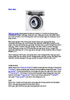
Illustration 3 Top of main control valves
g00344072
(8) Pilot line
b. Remove pilot line (8) from the connector that is located on top of main control valves (5). Install cap (6) on the connector. c. Install port connector (40), seal (39), adapter (38), seal (34) and nipple assembly (36) to the end of pilot line (8) .
https://127.0.0.1/sisweb/servlet/cat.dcs.sis.controller.techdoc.CSSISFormatTechDocForPrintServl... 1/14/2006
SUPPLEMENTARY SERVICE INFORMATION (DISASSEMBLY & ASSEMBLY) F 4MR00... Page 6 of 8
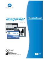
Illustration 4 Swing motor
g00344499
(1) Swing motor (2) Connector (4) Makeup line
d. Disconnect makeup line (4) from connector (2) at the top of swing motor (1) . e. Assemble and install seals (30), tee (3), swivel elbow (41), coupling (37), seal (34) and nipple assembly (36) to connector (2) at the top of swing motor (1) . f. Connect makeup line (4) to tee (3) . g. Connect portable hydraulic tester (7) and test hoses between nipple assembly (36) at pilot line (8) and nipple assembly (36) at the swing motor.
Illustration 5 Pilot oil manifold compartment
g00344078
(9) Pilot oil manifold (10) Pressure tap (15) Pilot relief valve
h. Install 6000 kPa (870 psi) pressure gauge (11) at pressure tap (10) on pilot oil manifold (9) . 5. Start the engine. 6. Place the machine controls at the following settings: Power Mode, engine speed dial "10" and AEC switch OFF. Make reference to Testing And Adjusting, "Operational Checks" for engine rpm settings. 7. Place the hydraulic activation control lever in the UNLOCKED position. 8. Increase the hydraulic oil temperature to 55° ± 5°C (131° ± 9°F). https://127.0.0.1/sisweb/servlet/cat.dcs.sis.controller.techdoc.CSSISFormatTechDocForPrintServl... 1/14/2006
SUPPLEMENTARY SERVICE INFORMATION (DISASSEMBLY & ASSEMBLY) F 4MR00... Page 7 of 8 9. Check the pilot relief valve setting at pressure gauge (11). The pressure gauge should show a reading of 4100 ± 200 kPa (595 ± 29 psi). If the pilot relief valve setting is not within the specification, adjust pilot relief valve (15). Refer to Testing and Adjusting, "Relief Valve (Pilot) - Test and Adjust" for adjustment procedures for the pilot relief valve.
Illustration 6 Portable hydraulic tester (flow meter)
g00344084
(7) Portable hydraulic tester (flow meter) (13) Multitach group (16) Valve (flow meter)
10. Turn valve (16) on portable hydraulic tester (7) clockwise until pressure gauge (11) at pressure tap (10) shows a reading of 4100 ± 200 kPa (595 ± 29 psi). 11. Record the pilot pump flow at 4100 ± 200 kPa (595 ± 29 psi) in Table 1. Table 1 Test Data For Pilot Pump Flow Oil Temperature °C (°F) Engine speed (rpm) Flow measured liter/min (US gpm) Flow corrected liter/min (US gpm) New
36 ± 2 (9.5 ± 0.5)
Specification for pump flow liter/min (US gpm) Service Limit
30 (7.9)
Note: Specifications for pump flow are based on an engine speed of 1800 rpm. To get more accurate test results, measured flow should be corrected by the following calculation. https://127.0.0.1/sisweb/servlet/cat.dcs.sis.controller.techdoc.CSSISFormatTechDocForPrintServl... 1/14/2006
SUPPLEMENTARY SERVICE INFORMATION (DISASSEMBLY & ASSEMBLY) F 4MR00... Page 8 of 8 Table 2 Measured flow x 1800 rpm Corrected flow
= measured rpm
Flow measurements must be done in pressure rise.
Copyright 1993 - 2006 Caterpillar Inc. All Rights Reserved. Private Network For SIS Licensees.
Sat Jan 14 15:22:23 UTC+0630 2006
https://127.0.0.1/sisweb/servlet/cat.dcs.sis.controller.techdoc.CSSISFormatTechDocForPrintServl... 1/14/2006