![Hyundai Getz Body Electric [PDF]](https://pdfs.asia/img/200x200/hyundai-getz-body-electric.jpg)
12 0 4 MB
Body Electrical
System GENERAL
FUSES AND RELAYS
SPECIFICATIONS ............................................. BE -3 SPECIAL TOOLS ............................................... BE -6 TROUBLESHOOTING ....................................... BE -7
AUDIO SYSTEM COMPONENTS ................................................. AUDIO UNIT COMPONENTS .......................................... REMOVAL AND INSTALLATION ................ INSPECTION .............................................. SPEAKERS REMOVAL AND INSTALLATION ................ INSPECTION .............................................. ANTENNA COMPONENTS .......................................... REMOVAL AND INSTALLATION ................
BE -29 BE -30 BE -33 BE -34 BE -35 BE -36 BE -37 BE -38
COMPONENTS ................................................. RELAY BOX (ENGINE COMPARTMENT) COMPONENTS .......................................... INSPECTION .............................................. RELAY BOX (PASSENGER COMPARTMENT) COMPONENTS .......................................... INSPECTION ..............................................
BE -62 BE -64 BE -65 BE -67 BE -69
INDICATORS AND GAUGES COMPONENTS ................................................. INSTRUMENT CLUSTER COMPONENTS .......................................... CIRCUIT DIAGRAM .................................... REMOVAL AND INSTALLATION ................ INSPECTION ..............................................
BE -71 BE BE BE BE
-72 -74 -76 -77
POWER DOOR LOCKS MULTI FUNCTION SWITCH COMPONENTS ................................................. BE -39 MULTI FUNCTION SWITCH REMOVAL AND INSTALLATION ................ BE -40 INSPECTION .............................................. BE -42
POWER DOOR MIRRORS
HORNS COMPONENTS ................................................. BE -44 HORN REMOVAL AND INSTALLATION ................ BE -45 INSPECTION .............................................. BE -45
KEYLESS ENTRY AND BURGLAR ALARM COMPONENTS ................................................. INSPECTION ..................................................... ETACS MODULE ANTI-THEFT FUNCTION ........................... TRANSMITTER INSPECTION .............................................. TRANSMITTER CODE REGISTRATION ...
COMPONENTS ................................................. BE -81 POWER DOOR LOCK ACTUATORS INSPECTION .............................................. BE -82 POWER DOOR LOCK RELAY INSPECTION .............................................. BE -84
BE -46 BE -47 BE -52 BE -55 BE -55
ETACS (ELECTRONIC TIME AND ALARM CONTROL SYSTEM) DESCRIPTION .................................................. BE -57 SPECIFICATIONS ............................................. BE -57 ELECTRONIC TIME AND ALARM CONTROL MODULE CIRCUIT DIAGRAM .................................... BE -58 REMOVAL AND INSTALLATION ................ BE -59 INSPECTION .............................................. BE -59
COMPONENTS ................................................. POWER DOOR MIRROR SWITCH CIRCUIT DIAGRAM .................................... INSPECTION .............................................. POWER DOOR MIRROR ACTUATOR INSPECTION ..............................................
BE -85 BE -86 BE -87 BE -88
POWER WINDOWS COMPONENTS ................................................. POWER WINDOW MOTOR INSPECTION .............................................. POWER WINDOW SWITCH CIRCUIT DIAGRAM .................................... INSPECTION ..............................................
BE -89 BE -90 BE -91 BE -92
REAR WINDOW DEFOGGER COMPONENTS ................................................. BE -94 REAR WINDOW DEFOGGER PRINTED HEATER INSPECTION .............................................. BE -95 REAR WINDOW DEFOGGER SWITCH INSPECTION .............................................. BE -97
WINDSHIELD WIPER /WASHER COMPONENTS ................................................. WINDSHIELD WIPER I WASHER SWITCH REMOVAL AND INSTALLATION ................ INSPECTION .............................................. FRONT WIPER MOTOR COMPONENTS .......................................... REMOVAL ................................................... INSPECTION .............................................. INSTALLATION ........................................... FRONT WASHER MOTOR REMOVAL AND INSTALLATION ................ INSPECTION ..............................................
LIGHTING SYSTEM BE -98 BE -99 BE -100 BE BE BE BE
-101 -102 -102 -103
BE -104 BE -104
REAR WIPER /WASHER REAR WIPER MOTOR COMPONENTS .......................................... REMOVAL ................................................... INSPECTION .............................................. INSTALLATION ........................................... REAR WAHSER SWITCH INSPECTION .............................................. REAR WAHSER MOTOR INSPECTION ..............................................
BE BE BE BE
-105 -106 -107 -107
BE -108 BE -109
SEAT WARMER COMPONENTS ................................................. BE -110 SEAT WARMER SWITCH INSPECTION .............................................. BE -110
BE -115 BE -116 BE -116 BE -119 BE -120 BE -121 BE -121 BE -122 BE -123 BE -124 BE -125 BE -125 BE -126 BE -127 BE -128 BE -129
HEAD LAMP LEVELLING DEVICE
SUNROOF COMPONENTS ................................................. SUNROOF SWITCH INSPECTION .............................................. SUNROOF RELAY INSPECTION .............................................. SUNROOF MOTOR INSPECTION ..............................................
COMPONENTS ................................................. HEAD LAMPS REMOVAL AND INSTALLATION ................ AIMING INSTRUCTIONS ........................... TURN SIGNAL LAMP REMOVAL AND INSTALLATION ................ ROOM LAMP INSPECTION .............................................. OVERHEAD CONSOLE LAMP REMOVAL AND INSTALLATION ................ INSPECTION .............................................. TURN I HAZARD LAMPS INSPECTION .............................................. FLASHER UNIT INSPECTION .............................................. RHEOSTAT INSPECTION .............................................. FRONT FOG LAMPS REMOVAL AND INSTALLATION ................ INSPECTION .............................................. REAR FOG LAMPS INSPECTION .............................................. TAIL, PARKING AND LICENSE LAMPS REMOVAL AND INSTALLATION ................ STOP LAMPS REMOVAL AND INSTALLATION ................ COURTESY AND TRUNK LAMPS REMOVAL AND INSTALLATION ................
BE -111 BE -112
COMPONENTS ................................................. BE -130 HEAD LAMP LEVELLING SWITCH CIRCUIT DIAGRAM .................................... BE -131 INSPECTION .............................................. BE -131
BE -113
IMMOBILIZER CONTROL SYSTEM BE -114
DESCRIPTION .................................................. BLOCK DIAGRAM ............................................. COMPONENTS ................................................. LIMP HOME FUNCTION ................................... DIAGNOSIS OF IMMOBILIZER FAULTS ..........
BE BE BE BE BE
-133 -135 -136 -138 -139
IGNITION SYSTEM IGNITION SWITCH REMOVAL AND INSTALLATION ................ BE -141 INSPECTION .............................................. BE -143
GENERAL
BE -3
GENERAL SPECIFICATIONS
E45BACD64
MULTIFUNCTION SWITCH Items
Specifications
Rated voltage
DC 12 V
Operating temperature range
-30°C - +80°C (-22 - + 176°F)
Rated load Dimmer & passing switch
Lighting switch Turn signal & lane change switch Wiper switch
Washer switch Rear wiper & washer switch
High : 230W (Lamp load) Low : 11 OW (Lamp load) Tail : 66W (Lamp load) Lighting : 21 W (Lamp load) 69W (Lamp load) Low, High : SA (Motor load) Intermittent : 7mA (Relay load) Lock : Max. 2SA (Motor load) SA (Motor load) Rear wiper : 3.SA (Motor load) Rear washer : SA (Motor load)
INSTRUMENTS AND WARNING SYSTEM Warning lamps
Bulb wattage (W)
Color
Illumination
GLS-L : 3.4W (4EA), 1.4W (1 EA) GL : 3.4W (3EA), 1.4W (1 EA) GLS-H : 3.4W (4EA), LED (3EA)
Green
High beam
1.4
Blue
Low fuel
1.4
Amber
Turn signal (LH, RH)
1.4
Green
Battery (charge)
1.4
Red
Oil pressure
1.4
Red
Air bag
1.4
Red
Parking brake
1.4
Red
Seat belt
1.4
Red
Check engine
1.4
Amber
ABS
1.4
Amber
Door ajar
1.4
Red
Tailgate open
1.4
Amber
Immobilizer
1.4
Amber
EPS
1.4
Red
OD OFF
1.4
Amber
BODY ELECTRICAL SYSTEM
BE -4 INDICATORS AND GAUGE Specifications
Items Speedometer Type
0
Cross-coil type
Input spec.
0
Hall IC type : 4 pulses/rev.
Indication
0
Km/h : 637rpm x 4 pulses/rev. indicates 60Km/h
0
MPH: 1024 rpm x 4 pulses/rev. indicates 60MPH
Standard values
Velocity (km/h)
20
40
60
80
100
Tolerance (km/h)
20-24.6
40-44
60.8-65.4
81.4-86.8
102.5-1 08.2
Velocity (km/h)
120
140
160
180
200
Tolerance (km/h)
123.5-129.6
144.4-151
165.4-172.4
186.3-193.8
207.2-215.2
Velocity (MPH)
10
20
40
60
Tolerance (MPH)
10-12.5
20-22.5
40-42.6
60-63.4
80
100
120
80.3-84.1 100.3-104.7 120.3-125.3
0
Tap the speedometer to prevent hysterisis effects during inspection.
0
Cross-coil type (4cyl: 2pulses/rev, 4cyl: 4pulses/rev)
Tachometer Type Standard values
Revolution (RPM)
1,000
2,000
3,000
4,000
5,000
6,000
7,000
Tolerance (RPM)
±100
±125
±150
±150
±150
±180
±210
0
Tap the tachometer to prevent hysterisis effects during inspection.
0
Cross - coil type (Fixed point type : Pointer should not fall into the "E" point but indicate remaining
Fuel gauge Type
fuel level when the ignition is off) Standard values Level
0
Gauge Resistance (n)
Gauge angle (')
E (Empty)
95
-40 ± 2.5
1/2
32.5
0±4.0
F (Full)
7.0
40 ± 2.5
Inspection order :
E-+F-+E
The level must be reached within 7 minutes after the resistance is set for Full or Empty. 0
Point stability tolerance : Within ±6. Apply power for 10 minutes. Then turn off the power for an hour and read the position of the pointer. ETPD001A
GENERAL
BE -5
Items
Specifications
Temperature gauge Type
0
Cross - coil type
Indication standard
0
Resistance of
Temperature
Angle C)
60"C
-40
-
85"C- 110"C
-7
+3
Red zone (over 125"C)
35±5
+7 -4
-2
Inspection order : OFF-+C-+H Temperature ("C)
temperature sender (NTC)
Assembled tolerance C)
Resistance (n)
60
85
110
125
Remark
118
49
25
14.6
Without trip computer
143.1
58.1
27.1
17.6
With trip computer
ETPD001B
LIGHTING SYSTEM Items
Bulb wattage (W) 60W /55W (High I Low beam)
Head lamp Front turn signal lamp
21W
Front position lamp
5W
Front fog lamp
27W
Rear combination lamps Tail/stop lamp Back up lamp Turn signal lamp
5W I 21W 21W 21W
Luggage lamp
5W
Room lamp
10W
Center high mounted stop lamp
16W
Overhead console lamp
10W
License plate lamp
5W
X X
2 2
AUDIO
K210, K220
K240, H280
Max. 20W x 2
Max. 20W x 4
4n x 4
4n x 4
AM/FM, LW/MW/FM
AM/FM, LW/MW/FM
Tuning type
PLL Synthesized type
PLL Synthesized type
Dark current
Max. 2m A
Max. 2mA
Items Rated output Load impedance Band
BE -6
BODY ELECTRICAL SYSTEM Items
K210, K220
K240, H280
AM : 531 - 1602KHZ/9 KHZ
AM: 531 - 1602KHZ/9KHZ
FM : 87.5 - 108MHZ/1 00 KHZ
FM: 87.5- 108 MHZ/100KHZ
LW : 153 - 279KHZ/1 KHZ
LW : 153 - 279 KHZ/1KHZ
MW : 522 - 1620KHZ/9KHZ
MW : 522 - 1620KHZ/9KHZ
FM : 87.5-108 MHZ/50KHZ
FM: 87.5-108 MHZ/50KHZ
Frequency range I Channel
WINDSHIELD WIPER AND WASHER Items
Specifications
Windshield wiper motor Rated voltage Operating voltage range Insulation resistance Speed/current at 1Nm load test
DC 12V DC 10-15V Min. 1Mn Low : 44-52 rpm/3.5A or less High : 64-78 rpm/4.5A or less Low : 39-47 rpm/5.5A or less High : 56-68 rpm/?.OA or less Low : 28Nm/24A or less High : 23Nm/28A or less
Speed/current at 4Nm load test Torque/current when parking Windshield & rear washer Motor type Pump type Rated voltage Discharge pressure Flow rate Current Overload capacity (Continuous operation) With water Without water (Racing)
60 sec. or less 20 sec. or less
Rear wiper motor Speed/current at no load test Speed/current at 1Nm load test Torque/current when parking Wiping angle at no load
38-50 rpm/2.0A or less 35-45 rpm/3.5A or less 8Nm/14A or less 173° ± 3°
SPECIAL TOOLS
DC ferrite magnet Centrifugal 12V 1.8kg/cm2 or more 1,500cc/min. or more 5.0A or less
E449ASD6F
Tool (Number and Name)
Illustration
Use
09900-21300 Keyless adapter
Store transmitter code connecting the DLC (Data Link Connector) cable of Hi-scan to the multi purpose check connector.
10021300
GENERAL
BE-7
TROUBLESHOOTING
E43047A23
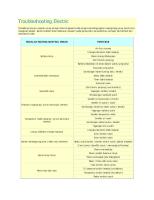
INSTRUMENTS AND WARNING SYSTEM Symptom
Possible cause
Remedy
Tachometer does not operate
No.7 fuse (10A) blown Tachometer faulty Wiring faulty
Check for short and replace fuse Check tachometer Repair if necessary
Fuel gauge does not operate
No.7 fuse (10A) blown Fuel gauge faulty Fuel sender faulty Wiring faulty
Check for short and replace fuse Check gauge Check fuel sender Repair if necessary
Low fuel warning lamp does not light
No.7 fuse (10A) blown Bulb burned out Fuel level sensor faulty Wiring or ground faulty
Check for short and replace fuse Replace bulb Check sensor Repair if necessary
Water temperature gauge does not operate
No.7 fuse (10A) blown Water temperature gauge faulty Water temperature sender faulty Wiring or ground faulty
Check for short and replace fuse Check gauge Check sender Repair if necessary
Oil pressure warning lamp does not light
No.7 fuse (10A) blown Bulb burned out Oil pressure switch faulty Wiring or ground faulty
Check for short and replace fuse Replace bulb Check switch Repair if necessary
Low brake fluid warning lamp does not light
No.7 fuse (10A) blown Bulb burned out Brake fluid level warning switch faulty Parking brake switch faulty Wiring or ground faulty
Check for short and replace fuse Replace bulb Check switch Check switch Repair if necessary
Open door warning lamp does not light
No.29 fuse (15A) blown Bulb burned out Door switch faulty Wiring or ground faulty
Check for short and replace fuse Replace bulb Check switch Repair if necessary
Seat belt warning lamp does not light
No.7 fuse (10A) blown Bulb burned out Buckle switch faulty Wiring or gound faulty
Check for short and replace fuse Replace bulb Check switch Repair if necessary
BODY ELECTRICAL SYSTEM
BE -8 LIGHTING SYSTEM Symptom
Possible cause
Remedy
One lamp does not light (all exterior)
Bulb burned out Socket, wiring or ground faulty
Replace bulb Repair if necessary
Head lamps do not light
Bulb burned out No.26, No.28 fuse (10A) blown Lighting switch faulty Wiring or ground faulty
Replace bulb Check for short and replace fuse Check switch Repair if necessary
Tail lamps and license plate lamps do not light
No.2, No.6 fuse (1 OA) blown Battery fusible link (50A) blown Tail lamp relay faulty Lighting switch faulty Wiring or ground faulty
Replace fuse and check for short Replace the fusible link Check relay Check switch Repair if necessary
Stop lamps do not light
No.19 fuse (15A) blown Stop lamp switch faulty Wiring or ground faulty
Replace fuse and check for short Adjust or replace switch Repair if necessary
Stop lamps stay on
Stop lamp switch faulty
Adjust or replace switch
Instrument lamps do not light (Tail lamps light)
Rheostat faulty Wiring or ground faulty
Check rheostat Repair if necessary
Turn signal lamp does not flash on one side
Bulb burned out Turn signal switch faulty Wiring or ground faulty
Replace bulb Check switch Repair if necessary
Turn signal lamps do not operate
No.5 fuse (1 OA) blown Flasher unit faulty Turn signal switch faulty Wiring or ground faulty
Replace fuse and check for short Check flasher unit Check switch Repair if necessary
Hazard warning lamps do not operate
No.20 fuse (15A) blown Flasher unit faulty Hazard switch faulty Hazard relay faulty Wiring or ground faulty
Replace fuse and check for short Check flasher unit Check switch Replace relay Repair if necessary
Flasher rate too slow or too fast
Lamps' wattages are smaller or larger than specified Defective flasher unit
Replace lamps Check flasher unit
Back up lamps do not light up
No.5 fuse (1 OA) blown Back up lamp switch faulty Wiring or ground faulty
Replace fuse and check for short Check switch Repair if necessary
Overhead console lamp does not light up
No.29 fuse (15A) blown Wiring or ground faulty
Replace fuse and check for short Repair if necessary
GENERAL
BE-9
AUDIO
There are six areas where a problem can occur: w1rmg harness, the radio, the cassette tape deck, the CD player, the speaker, and antenna. Troubleshooting enables you to confine the problem to a particular area.
Turn Ignition key to ACC position
Turn on the radio or the tape player I I
Verify customer complaint or identify symptom
I
I
I I
Sound
See CHART 1
I
I
I
Faint reception See CHARTS
Radio
I ICassette playerI I
See CHART2
I
See CHART3
I Poor volume SeeCHART7
I I
Noise
SeeCHART4
I
I
1) Place balance and fader control to center position. 2) Set volume control to proper position.
I CD player
See CHARTS
I
I
Seek/scan problem See CHARTS
I I Miscellaneous I
I
I
I "Eating" tape
I
SeeCHART9
ETPD001C
BE -10
BODY ELECTRICAL SYSTEM
CHART 1 Sound
1. Radio and tape player have no sound at all.
Check speaker connector Are all connectors behind radio and tape player properly connected ?
O.K.
Connect properly
Yes Temporarily install another speaker.
Is there voltage (12V) between terminal 16 of the M16 and body ground?
N.G.
Yes Are radio and player properly connected ?
Reinstall properly
Replace radio unit
Yes Check connection between output connector of radio and car.
O.K. Replace radio unit ETNC015A
BE -11
GENERAL
I 2. Tape player OK but no sound from radio I I
I
Check that the antenna isi--I___;Y:..::e:.:::s:._...--1 pluged into the radio. 1 1 Reinsert plug, O.K. ? No I
I
I
Insert properly
Not O.K. I I Does radio alone work ? No
11-_..!::0::.:.:.K'-!:·:._...~
1 Inspect antenna plug
1
~1--...;Y~e:..:s~~~
Replace radio
I
I
Temporarily install 11--_o;:;.:.:...K::....---1 Inspect antenna and another antenna. O.K.? antenna cable, and replace if necessary NotO.K.I
I
I
Replace radio
I ETA9010C
CHART 2
I
Radio problem
I
I
I
Weak
Poor tone
I
I
Check antenna (extend antenna fully)
Tune correctly. Still poor?
I Check connection of antenna plug
Check for shorts in speaker harness
I Temporarily install another antenna. O.K. ?
INot O.K. O.K.
I Replace radio
Replace antenna
Yes I Not O.K. 1 . 1 Repair harness
I
Not O.K. r . 1 Remove obJect
I
oKI Check for object lying on speaker and rattling OK' Extend antenna. Still poor ? Yes I Check antenna and lead-in for broken connectors. Does the tester indicate an open circuit ? No
Yes
: Replace antenna
I
: Replace radio unit
J
I
Is the broadcast quality the cause of poor tone quality ?
Yes
ETA9010D
0
:::1:
> ~
w
I
I
I
Remove obstruction
I
r
Play test tape
I I
O.K.
I I
Not O.K.
Play test tape
Will not accept or eject tape
Clean tape head and capstan (page BE-34)
L O.K.
N
l Low sound or poor sound quality
Check inside tape door for obstruction
m I ......
Cassette player
Dead
Not~
m
I
Not O.K.
Play test tape
I
Not O.K.
Not O.K.
INFORM CUSTOMER 1. To use good quality tape. 2. Don't put anything inside tape door except tape 3. Don't use C-120 type tape
Use a cotton swab dipped in isopropyl alcohol (refer to owner's manual) I O.K. Inspect by using test tape I 1
INFORM CUSTOMER 1. To use good quality tape. 2. To clean tape head and capstan at intervals of no more than 100 hours
m
0
~ m
r
m
0
I ~
§ 0
Remove unit for repair
I
.....
I
Replace radio unit
I
l:J
Replace radio unit
Replace radio unit
0 )> r
en -< en ..... m
s:::
BE -13
GENERAL CHART 4
1. RADIO
I
I
Noise I
I
Start the engine I
I
Tune correctly, still noise ?
I I
Yes I
I
I Not O.K. I
Check connectors
I
I
I
Fully insert connector
O.K.I I
Check mounting screws
I Not O.K. I
I
Tighten the screws
I
O.K.I lis the antenna lead-in routed too close to a harness ?
I I
Reroute the antenna lead-in
I
Replace radio unit
I
Yes
No I ON
When disconnecting the antenna lead, is there a noise ?
I No
I
"i
I
Yes I If noise still occurs after checking the above points, check for outside noise sources (various accessories, i.e. horn, wipers, etc.)
I Engine I
I I
OFF
I When disconnecting the ant-r enna lead, is there a noise ? 1
Is wiring correct ?
I No
Yes I
I
Yes
I
----1
Noise from outside source (No fault in radio unit)
I
No I
I
Repair harness
I ETA9010F
BE -14
BODY ELECTRICAL SYSTEM
2. TAPE
Noise
Start the engine
Not O.K.
Check ground
Ground completely
O.K. Not O.K.
Check mounting screws
Tighten the screws
O.K. O.K. Tape is defective
Check with another tape Not O.K. Yes
Is wiring correct ?
Replace radio unit
No Repair harness ETA9010G
CHART 5 1. CD WILL NOT BE ACCEPTED
No
Can you insert a CD ?
I
IYes Is CD rejected from approx. 15mm depth of the insertion panel even though CD can be inserted ?
I
A CD is already in the unit.
I
No
_j I
O.K.
I
No
_I
O.K.
I
IYes Though CD is completely inserted once, "error" is displayed and the CD is rejected ?
I
IYes Check CD. o Is the labeled side faced downward ? o Is the recorded face of the CD dirty ? o Does dew exist on the recorded face of the CD ?
INo
I
Replace CD player
Yes
I Insert the CD correctly or check to
I see if the CD is defective.
I
l I\9010H
GENERAL
BE -15
2. NO SOUND
H
Replace defective CD.
'~
Return it to normal temperature, and recheck operation. Does it operate properly ?
Does it play if a good quality CD is inserted ?
I
No
Does the "WAIT" indicator flicker?
I
No
Are the radio and CD player connected securely ?
~ O.K.
I
No No t---
Securely connect the radio and CD player.
Jves Repair or replace CD player if the combined radio cassette operates properly. ETA90100
3. CD SOUND SKIPS 1) Sound sometimes skips when parking. Is CD face scratched or dirty ?
lt-----'Y;....;;e'""s--1~
CD is defective, or clean CD.
~-----------~~N-0----------~ Does it play properly if CD is replaced t---N;..;.o..;;__~l Repair or replace CD player. with an existing proper CD ?
1
I I
lves Replace CD.
2) Sound sometimes skips when driving. (Stop vehicle, and check it.) (Check by using a CD which is free of scratches, dirt or other damage.)
Does sound skip when the side of the CD player is tapped ?
No
Check for skipping while driving and contact a service shop.
lves Securely mount the CD player. ETA90101
BE -16
BODY ELECTRICAL SYSTEM
4. SOUND QUALITY IS POOR
I
Does it play properly if another goodYes 1 Replace CD 1--------1 1 quality CD is loaded ? ~-----------------------~
Repair or replace CD player.
5. CD WILL NOT EJECT Is the ignition key at ACC or ON ?
I
No
~
Turn the key to ON.
I
No
~
Securely connect.
I
I
I
Yes
Is the combined amplifier or radio connected securely ?
I Yes If CD does not eject, don't try removing it. The player may be damaged. Therfore, contact a service shop for repairs.
6. NO SOUND FROM ONE SPEAKER Is CD player securely connected to the combined radio ?
No
: Securely connect them.
I
~
I
I
Yes
Does it play properly if another CD player is connected ?
Yes
Repair or replace CD player.
I No Repair or replace the combined radio. ETA9010J
BE -17
GENERAL CHART 6 Faint reception
Are both reception and static faint even when antenna is fully lengthened?
Temporarily install another speaker. O.K. ?
Replace speaker
No
No
Replace radio unit
Inspect antenna
Temporarily install another antenna. O.K. ?
Inspect antenna and cable and repair if necessary.
Replace radio
ETA9010K
CHART 7 Poor Volume
Does the problem disappear when switching from the cassette to the radio ?
No
Improperly connected harness or connector.
I
Correct the connection of the
I harness or the connector.
I
Yes Is the tape player head O.K. ?
1 No
Yes
Check for an improperly connected tape player head wire or a malfunction in the tape player itself. The tape being tested must be of good stereo quality.
Dirty, worn or damaged tape player head, improperly installed tape player head.
I
l
Correct the connection or replace the malfunctioning parts.
I Use tapes which have been I recorded in stereo.
i Clean or replace the tape player head.
I
I I ETA9010L
BE -18
BODY ELECTRICAL SYSTEM
CHART 8 Seek/scan problem
I Is antenna lead-in properly installed?
No
1 Install antenna properly
I
Yes! Check that the antenna is inserted completely into the antenna receptacle.
Not O.K. 1
1 Fully insert antenna
I
Yes : Replace antenna
I
O.K., Check antenna and lead-in for broken connectors. Tester indicates open circuit ? No
I
Replace radio unit ETA9010M
CHART 9 "Eating" tape
Check capstan and pinch roller 1!=~..:..:...!.:1 Clean head, capstan, and pinch roller. for oxide and dirt build-up Use head cleaner or isopropyl alcohol O.K.
O.K. Use C-30, 60, 90 tapes (C-120 tape is very thin and delicate) O.K. Check with another tape t-----t Tape is defective. Change tape ~----,-----~ Not O.K.
Replace tape player ETA9010N
GENERAL
BE -19
WINDSHIELD WIPER
1.
Wiper low and wiper high does not work.
Check No.21 fuse(20A) for short
NG
Replace the fuse
I
OK
Inspect the battery supply voltage of wiper switch between connector(M01-2) terminals 11 and 9. OK: Battery voltage (12V)
NG
Repair the wire harness and poor ground (G01)
OK
Wiper switch inspection (See the workshop manual page BE-1 00)
NG I
Replace the wiper switch
OK
Windshield wiper motor inspection (See the workshop manual page BE-1 02)
NG I
Replace the wiper motor
ETPD001E
2.
When washer switch is on, wiper does not work.
Check No.21 fuse(20A) for short
NG
I
Replace the fuse
I
OK
Inspect the input voltage of washer switch between connector (M01-2) terminal 15 and ground
NG
Repair the wire harness or the washer switch
OK
Refer to the above "1. Wiper does not work"
I ETPD001F
BODY ELECTRICAL SYSTEM
BE -20 POWER WINDOW
1.
No windows operate from the main switch on the driver's door.
No.19,23 fuse and fusible link short check
NG I
Replace fuse or fusible link
OK
Power window relay inspection (See the workshop manual page BE-66)
NG
Replace the relay
OK
Poor ground (G01) and the wire harness inspection
NG
Repair the wire harness and poor ground (G01)
ETPD001G
2.
Driver's side window does not operate.
Inspect the battery supply voltage of power window main switch between connector (005) terminals 10 and 11. OK : Battery voltage (12V)
NG
Repair the wire harness and poor ground (GOB)
OK
Power window main switch inspection (See the workshop manual page BE-92}
NG
Replace the power window main switch
OK
Driver's side power window motor inspection (See the workshop manual page BE-90)
NG
I
Replace the power window motor
I ETPD001H
GENERAL 3.
BE-21
Passenger's side window does not operate.
Inspect the battery supply voltage of passenger's side power window switch between connector (015) terminal 6 and ground. OK : Battery voltage (12V)
NG
Repair the wire harness and poor ground (G08)
OK
Passenger's side power window switch inspection (See the workshop manual page BE-93)
NG
I
Replace the power window switch
I
I
Replace the power window motor
I
OK
Passenger's side power window motor inspection (See the workshop manual page BE-90)
NG
ETPD0011
BE -22
BODY ELECTRICAL SYSTEM ~Since
POWER DOOR LOCK
door lock relay is fail, replace the door lock
relay. 1.
2.
I
Lock function works but unlock function does not interlock. ~ Since door unlock relay is fail, replace the door unlock relay.
3.
When passenger side knob is controlled, all doors interlocks, but when driver side knob is controlled, all doors do not interlock.
Unlock function works but lock function does not interlock.
Passenger's side actuator operation
NG
Connection rod defective of passenger's side door lock actuator
OK
I
Driver's side door lock switch inspection
NG
1. Input wiring short of driver's side door lock switch 2. Internal switch contact failure of driver's side door lock actuator
1. Check the wiring between connectors M25-2 ®and 009@. 2. Check the wiring between connector 009@ and ground (G08).
Measure resistance of actuator by handling it by the hand after connecting an ohmmeter to the both ends of actuator unit. Locked condition : oo Unlocked condition : Normal if it is below 1n [009]
@ OK
(Connector terminal of driver's side door lock actuator)
1. Output wiring short of all doors' lock actuator
Check the output wiring between door lock relay and all doors' actuator
2. All doors' lock actuator failure
Apply 12V to the both ends under uninstalled condition, and it's normal if it operates. [019/029/039]
g ttfj
(Connector terminal of all doors' lock actuator)
ETPD001J
BE -23
GENERAL 4.
When passenger side knob is controlled. All doors interlocks. But when the driver side knob is controlled, all doors do not interlock.
I Driver's side actuator operation :
NG
Connection rod defective of driver's side door lock actuator
OK
I
Passenger's side door lock switch inspection
I
NG
I
1. Input wiring short of passenger's side door lock switch 2. Internal switch contact failure of passenger's side door lock actuator
1. Check the wiring between connectors M25-20and 0190. 2. Check the wiring between connector 019® and ground (GO?).
Measure resistance of actuator by handling it by the hand after connecting an ohmmeter to the both ends of actuator unit. Locked condition : oo Unlocked condition : Normal if it is below 1n [019]
@ OK
(Connector terminal of passenger's side door lock actuator)
1. Output wiring short of all doors' lock actuator
Check the output wiring between door lock relay and all doors' actuator.
2. All doors' lock actuator failure
Apply 12V to the both ends under uninstalled condition, and it's normal if it operates. [009/029/039]
Q
C::±=fj
(Connector terminal of all doors' lock actuator)
ETPD001K
BE -24 5.
BODY ELECTRICAL SYSTEM
Both sides do not interlock either. NG No.11 fuse(20A) short check
I
I
Replace the fuse
I
I
Replace the relay
I
I
Check for an open in the wire
I
Check for an open in the wire
I
OK
Door lock/unlock relay inspection (See the workshop manual page BE-84)
NG
OK
Driver's side door lock switch input signal inspection (ETACS module connector M25-2 terminal@)
NG
I
OK
Passenger's side door lock switch input signal inspection (ETACS module connector M25-2 terminal@)
NG
I
OK
Replace the ETACS module
ETPD001L
BE -25
GENERAL KEYLESS ENTRY & BURGLAR ALARM SYSTEM
1.
Alarm does not work. (Hazard lamp works) NG No.20 fuse(15A) short check
Replace the fuse
I
I
OK
NG
Output wiring inspection of burglar alarm horn
Repair the wire harness and poor ground (G12)
OK
NG
Burglar alarm horn inspection (See the workshop manual page BE-51)
I
Replace the burglar alarm horn
I
OK
Replace the ETACS module ETPD001M
2.
When hood is opened inside the car like alarm test, horn does not work.
Check input wiring short of hood switch
1
NG Repair an open in the wire between connector (M25-2) terminal 8 and the hood switch (E38).
OK
Hood switch inspection (See the workshop manual page BE-50)
NG
I
Replace the hood switch
I
OK
Replace the ETACS module
ETPD001N
BE -26 3.
BODY ELECTRICAL SYSTEM
When door is opened inside the car like alarm test, horn does not work (If tailgate and hood is opened, alarm works)
Check input wiring short of all door switch
1
NG Repair an open in the wire between connector (M25-2) terminal 10, 11, 12 and the door switch.
OK
NG
All door switch inspection (See the workshop manual page BE-49)
I
Replace the door switch
I
OK
Replace the ETACS module
ETPD0010
4.
When tailgate is opened inside the car like alarm test, horn does not work.
Check input wiring short of tailgate switch
1
NG Repair an open in the wire between connector (M25-2) terminal 14 and the tailgate switch.
OK
Tail gate switch inspection (See the workshop manual page BE-50)
NG
I
Replace the tailgate switch
OK
Replace the ETACS module
ETPD001P
GENERAL 5.
BE -27
When the vehicle is locked by the transmitter, central door lock function works but hazard lamp doesn't blink.
Check input wiring short of all door switch
1
NG
Repair an open in the wire between connector (M25-2) and the door switch
OK
Check input wiring short of tailgate switch
NG
Repair an open in the wire between connector (M25-2) and the tailgate switch
OK
When checking hood switch under closed condition
Display open condition
Rubber at the above hood is not pressing enough the hood switch.
OK
Replace the ETACS module
ETPD001Q
6.
Engine does not start, when the alarm released condition.
Does the start motor move?
YES
Check the starting circuit
NO
Turn the key into start position as monitoring the start inhibit output
Change In on state ETACS module is currently alarm condition mode
Remain off Check the starting circuit
ETPD001R
BODY ELECTRICAL SYSTEM
BE -28 7.
Central door lock function works, but keyless entry system does not work.
YES
Does the transmitter lamp work when its button is depressed?
NO
Transmitter battery replacement
OK
•
•
Does the door lock or unlock when the transmitter button is depressed?
NG
After replacing transmitter, register the transmitter code using Hi-scan (See the workshop manual page BE-55)
OK Does the keyless entry operation work after removing the key?
NO
I
Normal
I
Since ETACS module is defective, replace ETACS module and register transmitter code
ETPD001S
AUDIO SYSTEM
BE -29
AUDIO SYSTEM COMPONENTS
E410C937E
Roof antenna
Rear door speaker
Front door speaker
Antenna feeder cable
Rear door speaker
Front door speaker
Audio unit
ETPD060A
BODY ELECTRICAL SYSTEM
BE -30
AUDIO UNIT COMPONENTS
E4085F1
[ 1