![I-Shift Generation C Design and Function [PDF]](https://pdfs.asia/img/200x200/i-shift-generation-c-design-and-function.jpg)
10 0 5 MB
Volvo Truck Corporation Göteborg, Sweden
Service Bulletin Trucks Date
Group
No.
Release
Page
12.2010
431
228
10
1(31)
I–Shift generation C Design and function FH, FM, FH16 AT2412C, AT2512C, AT2812C, ATO2512C, ATO3112C
I–Shift generation C, design and function
T4021207
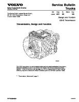
The service information describes the design and function of AT gearboxes.
88983778 ENG43273
English Printed in Sweden
Volvo Truck Corporation Service Bulletin
Gearbox, mechanical I-Shift, Generation C Contents
• • • • • • • • • • • • • • • • • • • • • •
“ General”, page 3 “ Gear ratio”, page 4 “ Gearbox construction”, page 4 “ Synchronisation”, page 6 “ Range housing”, page 6 “ Range gear”, page 6 “ Emergency steering servo pump”, page 7 “ Oil cooler”, page 7 “ Control housing”, page 8 “ Countershaft brake”, page 10 “ Clutch cylinder”, page 11 “ Lubrication system”, page 11 “ Ventilation”, page 14 “ Electrical system”, page 15 “ Compressed air system”, page 17 “ Power train”, page 18 “ Auxiliary brake lever”, page 24 “ Gear selector”, page 25 “ Display”, page 25 “ Program packages”, page 26 “ Function description”, page 28 “ Communication with other control units”, page 29
Date 12.2010
Group
No.
Release
431
228
10
Page 2(31)
Volvo Truck Corporation Service Bulletin
Date 12.2010
Group
No.
Release
431
228
10
General
T4021207
Make
VOLVO
Type
AT2412C AT2512C AT2812C ATO2512C ATO3112C
Unsynchronized main gearbox
ATO2512C
A - Automatic T - Transmission O - Overdrive 25 - Torque 2500 Nm 12 - Number of forward gears C - Generation
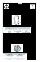
Symbols
Range gear
Synchronised
Split gear
Synchronised
Number of gears
Forwards
12
Reverse
4
AT2412C, AT2512C, ATO2512C
AT2812C, ATO3112C
Weight without oil
271 kg
277 kg
Length
891 mm
909 mm
Page 3(31)
Volvo Truck Corporation Service Bulletin
Date 12.2010
Group
No.
Release
431
228
10
Page 4(31)
Gear ratio Gear engaged
AT2412C, AT2512C, AT2812C
ATO2512C, ATO3112C
1st
14,94:1
11,73:1
2nd
11,73:1
9,21:1
3rd
9,04:1
7,09:1
4th
7,09:1
5,57:1
5th
5,54:1
4,35:1
6th
4,35:1
3,41:1
7th
3,44:1
2,70:1
8th
2,70:1
2,12:1
9th
2,08:1
1,63:1
10th
1,63:1
1,28:1
11th
1,27:1
1,00:1
12th
1,00:1
0,79:1
Reverse gear (R1)
17,48:1
13,73:1
Reverse gear (R2)
13,73:1
10,78:1
Reverse gear (R3)
4,02:1
3,16:1
Reverse gear (R4)
3,16:1
2,48:1
Gearbox construction The gearbox construction consists of three main parts: a clutch housing, a basic housing and a range housing. The clutch housing forms the front end plate of the gearbox. The base housing contains the main, counter
and reverse shafts along with a selector unit which is integrated into the control housing. The range housing contains the range gear planetary gear and the output shaft.
T4021405
1
Clutch housing
2
Main housing
3
Range housing for the retarder
Volvo Truck Corporation Service Bulletin The main parts in the gearbox are the input shaft, main shaft, range gear with selector unit, countershaft, oil pump with reverse shaft, as well as the control housing with selector unit.
Date 12.2010
Group
No.
Release
431
228
10
Page 5(31)
The range gear incorporates a planetary gear and is integrated with the output shaft. Gearboxes equipped with a power take-off also have a drive shaft fitted.
The trailing wheels for the reverse gear and basic gears are located on the main shaft. The range gear’s sun gear is also integrated with the main shaft. The countershaft has fixed gears.
T4021728
1
Input shaft
2
Main shaft
3
Range gear with selector unit and retarder drive
4
Countershaft
5
Oil pump with reverse shaft
6
Control housing with selector unit
7
Drive shaft for power take-off
Volvo Truck Corporation Service Bulletin
Date 12.2010
Group
No.
Release
431
228
10
Page 6(31)
Synchronisation
• • •
Split gear (A) is synchronized. The main gearbox housing (B) with its gears is not synchronized. Range gear (C) is synchronized.
T4021404
Range housing Range housing (C) can be combined with:
•
Power take-off; see option instructions for variants
• •
Emergency steering servo pump Retarder unit
Range gear The range synchronization lies outside the ring gear, reducing the unit’s length. The large synchronization area results in short selection time, the wide planet gears give
a strong range and the helical gears result in a quiet planet gear.
T4021725
Range gear with selector unit and retarder drive
Volvo Truck Corporation Service Bulletin
Date 12.2010
Group
No.
Release
431
228
10
Emergency steering servo pump The emergency steering servo pump is located on the gearbox and is driven by the gearbox output shaft. The emergency steering servo pump is activated when for some reason the normal power steering circuit fails.
T4021683
Emergency steering servo pump, PSS-DUAL
Oil cooler
T4021755
The gearbox oil cooler function is not affected by whether the gearbox has a retarder or not.
Page 7(31)
Volvo Truck Corporation Service Bulletin
Date 12.2010
Group
No.
Release
431
228
10
Page 8(31)
Control housing Gears are selected using the gear selector. Once a gear has been selected, the system reduces the engine torque to a suitable level, after which the gears are shifted to neutral.
After the gearbox has been put into neutral, the engine speed is adjusted to accommodate the speed of the selected gear, after which the gear shift takes place.
The control housing cover has two or sometimes three electrical sockets. When there is no retarder, the following applies: I Vehicle communication II Clutch cylinder III — The following applies with retarder: I Vehicle communication II Retarder III Clutch cylinder
T4018492
The control housing incorporates nine solenoid valves: 2.
Solenoid valve 2nd gear
LR.
Solenoid valve, low range
3.
Solenoid valve 3rd gear
HR.
Solenoid valve, high range
B.
Solenoid valve, brake
HS.
Solenoid valve, high split1
R.
Solenoid valve, reverse
LS.
Solenoid valve, low split1
1.
Solenoid valve 1st gear
1 HS and LS have reversed functions on Over Drive gearboxes.
T4018189
Volvo Truck Corporation Service Bulletin
Date 12.2010
Group
No.
Release
431
228
10
Page 9(31)
The control housing incorporates the following components:
• •
Four parallel cylinders, split, 1/R and 2/3 and range. Four inductive sensors for the positioning of the pistons.
•
Two speed sensors, one for the main shaft and one for the countershaft. The input shaft speed is set by the countershaft sensor.
•
An oil temperature sensor, selector forks for split gears and main gearbox. The oil temperature sensor is located on the cabling for the rpm sensor.
• •
A pressure sensor. Control unit for transmission, TECU. T4018494
Locations of cylinders and position sensor A. Split cylinder B. 1/R cylinder C. 2/3 cylinder D. Range cylinder E. Position sensor for the split cylinder
T4018201
Location of position sensor and speed sensor A. Position sensor range cylinder B. Speed sensor, countershaft C. Speed sensor, main shaft D. Position sensor, 2nd and 3rd cylinders E. Position sensor 1st and reverse cylinder
Volvo Truck Corporation Service Bulletin
Date 12.2010
Group
No.
Release
431
228
10
Parameter settings for installation of GCU-D (GCU-D: Gear Control Unit for I-Shift generation D) For more information regarding GCU-D and these parameters, see Function Group 4319, Information type Diagnostics MID 130 PID 160 Parametersetting.
T4057801
GCU
ID KBQ
KBR
Unit
Designation
0
The main shaft has a 72 teeth sensor wheel mounted
1
The main shaft has a 30 teeth sensor wheel mounted
0
There is a speed-sensor-D1 mounted
1
There is a speed-sensor-C2 mounted
1 Speed sensor for I-shift gearbox generation D 2 Speed sensor for I-shift gearbox generation C
Countershaft brake The counter shaft brake is located at the front of the counter shaft and brakes the rotating parts the gearbox when a start gear is selected, which eliminates gearbox wear, deposits and noise. The brake is also sometimes used during changing up to give quicker gear changes. It is activated using an integrated pneumatic cylinder.
T4021408
Countershaft brake
Page 10(31)
Volvo Truck Corporation Service Bulletin
Date 12.2010
Group
No.
Release
431
228
10
Clutch cylinder The clutch cylinder is located in the clutch housing, concentrically round the input shaft with a position sensor which measures clutch wear. A valve unit controls the clutch cylinder and is located on the outside of the clutch housing.
T4021655
A. Clutch cylinder B. Position sensor C. Valve unit D Bleeder nipple for the valve unit.
Lubrication system
T4023570
Page 11(31)
Volvo Truck Corporation Service Bulletin
Date 12.2010
Group
No.
Release
431
228
10
Page 12(31)
The gearbox is lubricated through a combination of pressure and splashing. The oil is led into the main shaft to lubricate and cool the range gears as well as the input and main shaft bearings. The countershaft brake, output shaft bearings, emergency steering servo pump drive, retarder gear and power take-off are also lubricated. The lubrication system has two overflow valves. One valve ensures that the gearbox is lubricated if the filter gets blocked while the other prevents excessive pressures in the system, e.g. during cold start. The valves are made up of a compression spring and a valve peg.
T4021730
The overflow valve which ensures that the gearbox is lubricated.
T4021729
Overflow valve which prevents excessive pressure.
Oil pump The oil pump is an eccentric pump driven by the countershaft via a gear. The pump is mounted in two needle bearings in the reverse shaft. There is a full flow oil filter of the insert filter type on the pressure side of the pump. It is located in the oil filter housing in the main housing. A support pipe is fitted in a cover that is fastened to the bottom of the oil filter housing. The support pipe prevents the filter, which sits on the outside, from collapsing.
T4021520
Volvo Truck Corporation Service Bulletin
Date 12.2010
Group
No.
Release
431
228
10
Oil level The oil level is checked with a level glass (2) and adjusted using two drain plugs (1A and 1B) and two filler plugs (3 and 4). Over-filled oil can also be adjusted using level plug (3). Read more about oil quality and oil change volumes inFunction Group 1750, Information type Service and maintenance Preventive maintenance intervals.
T4021684
Level glass for checking oil level
T4033600
1A. Drain plug 1B. Drain plug 2. Level glass 3. Filler plug/level plug 4. Filler plug / Vent valve
Page 13(31)
Volvo Truck Corporation Service Bulletin
Date 12.2010
Ventilation Ventilation is via a hose that passes over the control housing and down behind the valve unit.
T4021686
Group
No.
Release
431
228
10
Page 14(31)
Volvo Truck Corporation Service Bulletin
Date 12.2010
Group
No.
Release
431
228
10
Page 15(31)
Electrical system Sensors and sockets, for gearboxes without a retarder
T4021412 T4021414
I. Vehicle communication
Cabling from socket II to the valve unit for the clutch cylinder.
II. Clutch cylinder A. Speed sensor
T4021413
Cabling from socket I to the speed sensor and chassis cabling.
Volvo Truck Corporation Service Bulletin
Date 12.2010
Group
No.
Release
431
228
10
Page 16(31)
Sensors and sockets, for gearboxes with a retarder
T4021410 T4021409
Cabling from socket II to the retarder. I. Vehicle communication II. Retarder III. Clutch cylinder A. Speed sensor
T4021418
Cabling from socket III to the valve unit for the clutch cylinder.
T4021411
Cabling from socket I to the speed sensor and chassis cabling.
Volvo Truck Corporation Service Bulletin
Date 12.2010
Group
No.
Release
431
228
10
Page 17(31)
Compressed air system Compressed air connections
T4021415
Compressed air connection between the control housing and the valve unit for the clutch cylinder.
T4021417
Pneumatic connection between the control housing and the countershaft brake.
T4021416
For the high pressure system, compressed air connection between the control housing and the four-circuit valve. For the low pressure system, compressed air connection between the control housing and the pneumatic tank.
Volvo Truck Corporation Service Bulletin
Date 12.2010
Group
No.
Release
431
228
10
Power train The following illustrations show the power train for AT2412C, AT2512C and AT2812C.
T4021694
T4021693
1st gear
2nd gear
T4021696
T4021695
3rd gear
4th gear
T4021698
T4021697
5th gear
6th gear
Page 18(31)
Volvo Truck Corporation Service Bulletin
Date 12.2010
Group
No.
Release
431
228
10
T4021700
T4021699
7th gear
8th gear
T4021702
T4021701
9th gear
10th gear
T4021704
T4021703
11th gear
12th gear
Page 19(31)
Volvo Truck Corporation Service Bulletin
Date 12.2010
Group
No.
Release
431
228
10
T4021691
Neutral N1
T4021692
Neutral N2
T4021687
Reverse gear (R1)
T4021688
Reverse gear (R2)
T4021690
T4021689
Reverse gear (R3)
Reverse gear (R4)
Page 20(31)
Volvo Truck Corporation Service Bulletin
Date 12.2010
Group
No.
Release
431
228
10
The following illustrations show the power train for ATO2512C and ATO3112C.
T4021712
T4021711
1st gear
2nd gear
T4021713
3rd gear
T4021714
4th gear
T4021715
T4021716
5th gear
6th gear
Page 21(31)
Volvo Truck Corporation Service Bulletin
Date 12.2010
Group
No.
Release
431
228
10
T4021718
T4021717
7th gear
8th gear
T4021719
9th gear
T4021720
10th gear
T4021722
T4021721
11th gear
12th gear
Page 22(31)
Volvo Truck Corporation Service Bulletin
Date 12.2010
Group
No.
Release
431
228
10
T4021710
T4021709
Neutral N1
Neutral N2
T4021705
Reverse gear (R1)
T4021706
Reverse gear (R2)
T4021707
Reverse gear (R3)
T4021708
Reverse gear (R4)
Page 23(31)
Volvo Truck Corporation Service Bulletin
Date 12.2010
Group
No.
Release
431
228
10
Page 24(31)
Auxiliary brake lever On all vehicles with a retarder and on vehicles with an automatic gearbox and engine brake (VEB) the auxiliary brake is applied using a lever on the steering shaft. 0 Auxiliary brake not applied A Automatic mode 1–3 Manual mode B Position for activating the brake program. Spring return to position 3.
T5012243
The illustration shows a vehicle fitted with the “Basic” program set, which has no brake program. When the auxiliary brake lever is moved to position B, the gearbox will select a gear giving an engine speed of just over 1500 rpm. If the speed in reduced, the gearbox will then select gears to maintain an engine speed between 1000-1500 rpm (B). The driver can also change down further by moving the auxiliary brake lever to position B.
T4022470
Without the brake program, (A) desired rpm for first change down, (B) area for braking using the auxiliary brake.
The vehicle in the illustration is fitted with one of the program sets “ Distribution & Construction”, “Long Haul Fuel & Economy” or “ Heavy Duty GCM Control”, which include the braking program. When the auxiliary brake lever is moved to position B, the gearbox will select a gear giving an engine speed above 1500 rpm. The gearbox will then select gears to maintain an engine speed above 1500 rpm (B).
T4022471
With the brake program, (B) area for braking using the auxiliary brake.
Note: The effect of the auxiliary brake may be reduced by the I-shift control unit, MID 130, to make the ride as comfortable as possible. The effect reduction is regulated by the selected gear, vehicle weight and road surface inclination.
For more information on auxiliary brake component parts, see group 21, Description, Design and Function, “Engine”.
Volvo Truck Corporation Service Bulletin
Date 12.2010
Group
No.
Release
431
228
10
Gear selector Gear selector (GLU) is attached to the driver’s seat and can be folded away to ease passage inside the cab. The gear selector control unit is in the dashboard. The gear selector incorporates the following functions: 1
Three position switch with spring return for up and down changing.
2 Button for lowering the lever into a horizontal position. 3
Gear selector inhibitor preventing the vehicle from being put in gear unintentionally.
4 Gear selector position: R = reverse gear N = neutral A = automatic M = manual
T4022483
5 Button E/P for economy/performance position. 6
Button L “Limp Home”.
Note: The “ Limp Home” function is intended for moving the vehicle short distances in order to get off the road and to a workshop. Only one gear can be used and the driving may be jerky. For information on how to engage and use this function, see driver instructions.
Display The display provides information on the gear currently selected and which gears are available. The display is divided into smaller fields showing: 1
Driving program
2
Selected gear
3
Available gears (down/up)
4
Lever position
T3014422
Page 25(31)
Volvo Truck Corporation Service Bulletin
Date 12.2010
Group
No.
Release
431
228
10
Page 26(31)
Program packages General notes on the program packages The gearbox has different functions depending on which program package is installed in the gearbox. The following program packages are available:
• • • •
Display
Program packages
VDA variants
B
Basic
TP-BAS
Basic is the standard gearbox program
DC
TP-DICON
Distribution & Construction include functions that make the truck lighter to manoeuvre.
Distribution & Construction
FE
Long Haul Fuel & Economy
TP-FUEC
HD
Heavy Duty GCM Control
TP-HD
Long Haul Fuel & Economy include functions that partly improve fuel consumption and partly make the truck lighter to manoeuvre. Heavy Duty GCM Control is designed for heavy trucks. This program also contains functions that help to improve fuel consumption and make the truck easier to manoeuvre.
Which program package is installed in the vehicle? When the gear selector is in neutral position (N) and the “FOLD ” button is pressed in, the lever can be folded forwards. The display then shows the program variant the gearbox has.
Change program package When a program package is replaced, the “Central system (VDA)” must be updated before it can be downloaded to the vehicle. This is done by entering the “Converting set number” in the computer tool which is stated in “ Part information, accessory”. After replacement, reprogramming must be carried out using the TECU control unit (MID 130), and the gearbox must be recalibrated.
Functions in every program package Long Haul Fuel & Economy
Heavy Duty GCM Control
I-Roll
X
X
Smart Cruise Control
X
X
Function
Distribution & Construction
Basic
Launch Control
X
X
X
Enhanced Shift Strategy (GCM ≤ 60 T)
X
X
X
Heavy Duty GCM Control (60 T < GCM ≤ 180 T) Possible optional functions
X Distribution & Construction
Basic
Gear Selection Adjustment in Auto including Kickdown Enhanced Power Take Off Functions
X
Long Haul Fuel & Economy
Heavy Duty GCM Control
X
X
X
X
X
X
Variant
Installed
Not installed
AMSO-AUT
X
Variant for optional functions Name Gear Selection Adjustment in Auto
Enhanced Power Take Off Functions
X
AMSO-BAS APF-ENH APF-BAS
X X
Customer parameters Customer parameters in the gearbox control unit:
Note: The default value can vary depending on the program package selected.
Volvo Truck Corporation Service Bulletin
Date 12.2010
Group
No.
Release
431
228
10
Page 27(31)
ID
Designation
FZC
Highest used start gear (1 – 6).
GJJ
Load on the engine PTO even when it is deactivated.1
No
Yes/No
GJI
Determines whether the transmission is disconnected from the clutch in “Auto Neutral”.1 2
No
Yes/No
GJG
Determines how the split gear performs when PTO 1 is connected for the gearbox.1
Selectable
LS/HS/Selectable
GJH
Determines how the split gear performs when PTO 2 is connected for the gearbox.1
Selectable
LS/HS/Selectable
IEO
Determines how the transmission performance mode is handled: Manual: Performance mode available. Auto: Performance mode available. The transmission will automatically return to Economy mode when the engine is no longer operating under high load. Disable: Performance mode not available.
Auto
Manual/Auto/Disabled
1 For further information, see options instructions. 2 GJI only used at APF-ENH; the others are always included.
Default Value
Unit
6
Volvo Truck Corporation Service Bulletin
Date 12.2010
Group
No.
Release
431
228
10
Page 28(31)
Function description Standard functions The following standard functions are available in the gearbox:
• •
•
Automatic choice of start gear.
A display that shows the gearbox oil temperature and a warning system that informs the driver when the oil temperature is too high.
Possibility to change automatically selected gears when the accelerator pedal is released.
Optional functions
•
•
•
I-Roll (VEB or retarder required) This function automatically engages and disengages the freewheel to reduce fuel consumption. When you release the accelerator, the transmission shifts to neutral, so that the vehicle can roll freely and the engine goes down to idle. Smart Cruise Control The function is only active when cruise control is activated. Saves fuel by deactivating the auxiliary brakes under certain conditions. The function releases the auxiliary brakes after a downhill stretch, which improves cruise control performance.
Automatically selects the lowest possible gear when the air suspension is in manual mode in order to obtain optimal manoeuvrability. ECS required. Improves engine brake performance by selecting gears that increase engine speed. Temporarily applies the wheel brakes when changing gear to compensate for the engine brake when the brake program is active. This function requires ABS-EBS. If a trailer without ABS is hitched up, the function is deactivated.
•
Heavy Duty GCM Control This function makes it possible to adjust the gearing strategy to suit the rolling weight - up to 180 tonne.
•
Gear Selection Adjustment in Auto including Kickdown The function makes it possible to adjust automatically selected gears even when the accelerator pedal is depressed. There is also a Kick Down function for maximising the acceleration of the vehicle.
•
Enhanced Power Take Off Functions Optional functions that support power take-off operations, e.g. “Auto Neutral” and splitbox. Optional functions:
Launch Control Allows driving with the engine idling without slipping the clutch. Regulates engine torque when pulling away for optimum gear changing and avoid high engine speed. The following functions in “Launch control” require EBS: Improved comfort when pulling-up through smoother disengagement when pressing lightly on the brake pedal. Automatic application of the brakes when the vehicle rolls in the wrong direction, in relation to the selected gear. Automatic application of the brakes to stop the vehicle and change from a forward to a reverse gear or vice versa. HSA, “Hill Start Aid”, which is only active on inclines. See also the description of “Hill Start Aid”: Function group 593, Information type Description “Electronically controlled braking system (EBS)”.
•
Enhanced Shift Strategy
Makes it possible to determine software parameters that limit engine speed when power take-off is used. The function forms a gear selection strategy to suit engine speed limitations. Disengages the transmission at the request of the options module, irrespective of the gear lever position, when “Auto Neutral” is activated. Blocks reverse gear when the options module requests “ reverse inhibit”. Makes it possible to use the splitbox for driving the power take-off at high capacity.
Volvo Truck Corporation Service Bulletin
Date 12.2010
Group
No.
Release
431
228
10
Communication with other control units Summary, components (signal summary)
T4058439
Component list Description
Component A03 (MID 140)
Central instruments
A12 (MID 136)
Control unit, ABS
A13 (MID 130)
Control unit, TECU (transmission electronic control unit)
A14 (MID 128)
Control unit, EECU (engine electronic control unit)
A16 (MID 150)
Control unit, ECS (electronically controlled suspension)
A17 (MID 144)
Control unit, VECU (vehicle electronic control unit)
A21 (MID 136)
Control unit, EBS (electronically-controlled brake system)
A27 (MID 216)
Control unit, LCM (external lighting)
A33 (MID 220)
Tachograph
A36 (MID 249)
Control unit, BBM (body builder module)
A41 (MID 222)
Control unit, RECU (retarder control unit)
A109 (MID 223)
Control unit, GSECU (gear selection electronic control unit)
B04
Sensor, engine speed, crankshaft
B12
Sensor, tachograph/speedometer
Page 29(31)
Volvo Truck Corporation Service Bulletin B13-73 B25 B55-58
Group
No.
Release
431
228
10
Page 30(31)
Sensor, wheel speed Sensor, accelerator pedal Sensor, air pressure in air spring bellows
B175
Sensor, load indicator
S07
Switch, engine brake
S08/S09
Date 12.2010
Switch, differential lock
S24
Retarder stalk switch
S25
Switch, cruise control
S28
Power take-off switch
S59
Position switch, brake pedal, NO
S171
Gear lever, GLU
XO5
Trailer connector, 7-pin, 24 S
Y39
Solenoid valve, VEB (Volvo engine brake)
Communication with control unit VECU (A17), MID 144 Signals / information to TECU:
• • • •
The vehicle control unit parameters MG, MH and AQ must have the same values. Check the parameter settings in the VDA. Accelerator pedal position, including “kick-down”. Cruise control.
• • • • •
Retarder control. For further fault tracing see the PC-tool, function group 5.
Power take-off control, see options instructions. Brake pedal position. Parking brake applied or not. The VECU K-factor must be the same as the tachograph K-factor. Vehicle weight information on leaf suspension vehicles ( RADD-BR and RADD-TR), used for gear selection.
Communication with the control unit Central instruments (A03), MID 140 Signals / information from TECU:
• • • • •
•
When using the power take-off, the driver can choose between N1=low split and N2=high split for different PTO gear ratios, see the options instructions.
•
When the gear lever is in neutral position (N) and the button “ FOLD” is pressed in, the lever can be folded forwards, and the display shows which program set the gearbox has.
Gear selector, positions. Gear selected. Possible gears. Driving program E/P. Time and date for diagnostics.
Communication with control unit EECU (A14), MID 128 Signals / information to TECU:
• •
Engine speed.
• •
Engine configuration
Engine torque If the engine is not running smoothly, this will adversely affect gear shifting.
Communication with control unit ABS/EBS (A12/A21), MID 136 Signals / information to TECU:
•
• •
If “Traction Control” is disengaged via the display, the gearbox may change gear due to spinning.
•
In “Launch Control” the gearbox can control the brakes. For more detailed information, see “ Function description”, page 28 for “ Launch Control”.
• •
Wheel speed sensor. Wheel spin information; the vehicle does not change gear. ABS system active, the vehicle does not change gear. Information from ESP, the vehicle does not change gear.
Communication with control unit ECS (A16), MID 150 Signals / information to TECU:
•
Vehicle weight.
•
ECS control unit status. Always start in 1st gear if the manoeuvre control unit for the air suspension is in manual mode.
Volvo Truck Corporation Service Bulletin
Date 12.2010
Group
No.
Release
431
228
10
Page 31(31)
Communication with control unit LCM (A27), MID 216 Signals / information to TECU:
•
•
Trailer coupled.
The gearbox can select the wrong start gear and wrong gears if the parameter “ANI” is not active. The gearbox then assumes that a trailer is hitched up.
Communication with control unit BBM, MID 249 Signals / information to TECU:
•
Power take-off (PTO) engagement.
•
Power take-off switch control.