![Kanto Seiki Support Manual [PDF]](https://pdfs.asia/img/200x200/kanto-seiki-support-manual.jpg)
16 0 136 KB
Support manual
Service section TEL 027-251-2123 FAX 027-290-1881
KANTO SEIKI
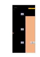
■Operating and stopping method : (1)Operating method:Press ①"POW"key until ⑧"RUN" lamp lights up to operate OILMATIC. ⑦Parameter LED (2)Stopping method:Press1①"POW"key until ⑧"RUN" lamp turns off to stop OILMATIC. (3)Operating and stopping by the external starting signal:When a No.14,19 terminals (for the exclusive use of external starting ) ⑧RUN lamp are received the external starting signal from the main machine,the OILMATIC operats and terminated OILMATIC stops. ■Setting and canceling key lock method : (1)Setting key lock method:Press ⑤"UP"and ④"DOWN"keys simultaneously until "LED" on lower right ⑥"LED" area blinks to deactivate all key operation excluding ①"POW" key. (2)Canceling key lock method:Press ⑤"UP"and ④"DOWN"keys simultaneously until "LED" on lower right ⑥"LED" area turns off to activate all key operaions. ■Selecting temperature control method : (1)Changing base temperature follow up mode or constant mode:Press both ②"PARA"and ③"ENT" keys and also either ⑤"UP" key or ④"DOWN" key to make a change. The change of setting is completed upon release of the ②"PARA" and ③"ENT" keys. The ⑥"LED",⑦"LED" corresponding under the diagram.
⑥DATA LED ⑤UP key
RUN
UP PARA
POW
TMR
DATA
PARA
④DOWN key ①POW key
⑥Data LED ⑦Parameter LED Control mode A Base temperature follow up mode . E Constant mode. C F ※A standard model controls inlet temperature.If you change it into outlet temperature control mode.Please attach the connector remove from inlet temperature sensor to outlet temperature sensor in control box and change the system parameters at once.
②PARA key ③ENT key
Setting key lock
+
L 45 5 FIL
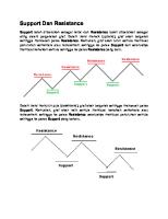
Cause RP(Reverse phase protective relay) or OL1(Pump moter protective device)is actuated THP, ITS(Compressor temp. protective switch ) or GPS(Refrigeration pressure switch) is actuated. The Connection failure between the inverter PCB and the main PCB. The CPU mounting the inverter PCB unusual. Over current of HIC(Inverter power IC)or heated up. Over current primary of inverter PCB. HTS1 or HTS2(Heater temp. protective switch) is actuated.
DOWN
Cope
Prease refer to an instruction manual 8-1.
PARA
+
ENT
+
The base temperature sensor is not connects. The room temrerature sensor is not connects. The control liquid temperature is higher than temperature the sum of the set temperature and the maximum alarm. The control liquid temperature is lower than the set temperature minus the minimum alarm temperature. The control liquid temperature is higher than 45 degree. The control liquid temperature is lower than 5 degree. Filter clogging.
※About besides,please refer to "Service Manual"attached with Oilmatic.
UP
or DOWN
Simultaneous
The inlet temperature sensor is not connects.(The preparation sensor is not connects in case of PID control.) The outlet temperature sensor is not connects. (The liquid control sensor is not connects in case of PID control)
Canceling key lock
UP Simultaneous
■Indication on the control panel and how to cope : Indication AL1 AL2 AL30 AL31 AL32 AL33 AL4 AL61 AL62 AL63 AL64 H
DOWN
ENT
Please confirm conection of the sensor. ※In case of wire is broken,please exchange a new sensor.
Prease refer to an instruction manual 8-1.
Follow up ↑↓ Constant
⑥"LED"indicates liquid temperature
PARA
+ ENT
Release Prease refer to an instruction manual and cleaning of air filter.