![LCM500 UserGuide RD [PDF]](https://pdfs.asia/img/200x200/lcm500-userguide-rd.jpg)
24 0 2 MB
Do Not Print This Sheet
Notes. 1). Finished Document, excluding this Sheet, to be: Portrait. Color. Doubled Sided. Ring Bound. 2). Finished document is electronically filed as 72X-0058-01.pdf.
D
20761
Fixed negative numbering on pages 60,61,62,63.
C
20720
B
----
A
20471
Initial Issue
REV
ECN
DESCRIPTION OF CHANGE
Changed Revision to D
NN
05/10/2018
Updated. contact information, Clarified section on third harmonic current
NN
04/23/2018
Draft.
----
----
NN
11/03/2017
APPR
DATE
Not released in Omnify
This document and all its contents are the sole and exclusive property of Doble Engineering Company. Unauthorized copying, use, and/or distribution of this document or any portion thereof is hereby expressly prohibited.
D O B L E E NG INE E RING C O . Watertow n, Mass. 02472 TITLE
User Guide, Leakage Current Monitor, LCM500 DRAWING NO.
72X-0058-01
SHEET
OF
1
REV
1
D
LCM500 Leakage Current Monitor User Guide
Chief Safety Hazards for the LCM500 These chief safety hazards accompany the use of the LCM500: • • •
Electrical hazards are always present in substations. Always keep the LCM500 and yourself within published safe-approach distances to energized conductors. Thunderstorms: Never operate the LCM500 when there are thunderstorms in the area. Switching overvoltages: Never operate the LCM500 when switching overvoltages are likely to occur.
Overview of this User Guide This user guide explains how to use the hardware and firmware of the Doble LCM500 Leakage Current Monitor for metal oxide surge arresters. The LCM500 can test the condition of all makes of metal oxide surge arresters (MOSAs) that are mounted on an insulated base. It cannot test surge arresters that are directly grounded to the system ground of the substation, with no separate ground lead. The firmware discussed in this guide is version 1.28 or later.
Who Should Read This Guide This guide is intended for anyone using the LCM500. It is assumed that you are familiar with professional standards and safety practices.
Notice Doble and the Doble logo are trademarks of Doble Engineering Company. Microsoft, Windows, Windows 95, Windows 98, Windows 2000, Windows NT, XP, Vista, and Windows 7 are registered trademarks of Microsoft Corporation in the United States and/or other countries. Copyright ©1999-2018 By Doble Engineering Company All Rights Reserved Your use of this manual is further subject to the legal restrictions and notices of law as detailed further in Appendix D. By reading or otherwise accessing or using this manual, you are agreeing to abide by such restrictions and laws.
Contents 1. Test Procedures .............................................................................. 6 Requirements for Condition Monitoring ................................................................ 6 Typical Hardware Setup ....................................................................................... 7 Step 1: Ground the System .................................................................................. 8 Step 2: Install the CCT500 ................................................................................... 8 Step 3: Install the Field Probe .............................................................................. 9 Positioning the Field Probe Correctly............................................................. 10 Procedure ...................................................................................................... 10 Step 4: Enter Test Parameters ........................................................................... 11 Using the Hardware Controls to Enter Values ............................................... 11 Procedure ...................................................................................................... 13 Step 5: Run the Test .......................................................................................... 17 Manual Testing .............................................................................................. 17 Third Harmonic Current ................................................................................. 18 Automatic Testing .......................................................................................... 19 Step 6: Store the Results of Manual Tests in the LCM500 ................................ 21 Storing Results for Identified Arresters .......................................................... 21 Storing Test Results for Unidentified Arresters.............................................. 21 Viewing Stored Test Results.......................................................................... 22 Understanding the Test Results Display........................................................ 23 Step 7: Transfer the Test Results to the PC ...................................................... 24 Step 8: Disassemble the Test Setup .................................................................. 24
2. Troubleshooting ............................................................................ 25 Error Messages .................................................................................................. 25 LCM500 Support at Doble .................................................................................. 27
72X-0058-01
Rev D
3
5/2018
LCM500 Leakage Current Monitor User Guide
3. Overview of the LCM500 .............................................................. 29 Introduction ........................................................................................................ 29 Required MOSA Configuration ...................................................................... 29 Factors Affecting MOSA Condition ................................................................ 29 Two Types of LCM500 Testing ...................................................................... 29 A Four-Part System ....................................................................................... 30 Normalized Data ............................................................................................ 30 Measurement Method .................................................................................... 31 Additional Application..................................................................................... 32 Unpacking and Inventory Check ........................................................................ 32 Hardware Overview ............................................................................................ 33 LCM500 Power Sources and LED Indicators ..................................................... 34 LCM500 Power Sources ................................................................................ 34 LCM500 LED Power Indicators...................................................................... 35 Probes ................................................................................................................ 36 Behavior of Probe LEDs ................................................................................ 36 Charging the Probes ...................................................................................... 37 Wireless Communication Between Probes and LCM500 Instrument ............ 38
4. Testing the LCM500 ...................................................................... 39 Functional Test of Measuring System ................................................................ 39 Test Procedure .............................................................................................. 39 Simulation Testing a Second LCM500 ............................................................... 42
5. System Software and USB Driver ................................................. 43 Setting Basic Parameters ................................................................................... 43 Setting the Ethernet Connection ........................................................................ 44 Setting Wireless Communication Parameters .................................................... 44 Inverting the Display Backlight ........................................................................... 45 Transferring Arrester IDs to the LCM500 ........................................................... 46 Manually Install the USB Driver ......................................................................... 46
A. Specifications ............................................................................... 47
72X-0058-01
Rev D
4
5/2018
LCM500 Leakage Current Monitor User Guide
B. Parts ............................................................................................. 49 C. Influence of Temperature and Operating Voltage ......................... 54 D. Legal Notice .................................................................................. 56
72X-0058-01
Rev D
5
5/2018
1. Test Procedures This chapter provides a basic procedure for setting up and running a test. • • • • • • • •
“Requirements for Condition Monitoring” on page 6 “Typical Hardware Setup” on page 7 “Step 1: Ground the System” on page 8 “Step 2: Install the CCT500” on page 8 “Step 3: Install the Field Probe” on page 9 “Step 4: Enter Test Parameters” on page 11 “Step 5: Run the Test” on page 17 “Step 6: Store the Results of Manual Tests in the LCM500” on page 21 • “Step 7: Transfer the Test Results to the PC” on page 24 • “Step 8: Disassemble the Test Setup” on page 24
Requirements for Condition Monitoring
72X-0058-01
Rev D
Before you begin condition monitoring of MOSAs, ensure that: • The arrester base is insulated from the ground. For example, the arrester can be mounted on an insulated base. • The arrester is grounded through a single grounding wire, preferably insulated. • There are no thunderstorms in the vicinity.
6
5/2018
LCM500 Leakage Current Monitor User Guide
Typical Hardware Setup
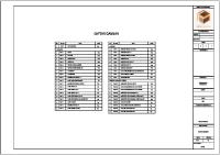
Figure 1 shows a typical test setup for the LCM500 system. A
B
A B
Clip-on current transformer CCT500—Measures the total leakage current in the grounding cable. Field Probe (antenna) FP500—Measures the electrical field at the base of the arrester. Must electrically float during measurements. Can be operated by a hot-stick or Field Probe Rod to reach the vicinity of the arrester base.
Figure 1 Typical Test Setup for LCM500 System
72X-0058-01
Rev D
7
5/2018
LCM500 Leakage Current Monitor User Guide
Step 1: Ground the System
A special plug on the LCM500 has ensures that both the power supply cable and the grounding wire have a good connection to the instrument. Follow the grounding instructions that are appropriate for your location and power supply: • Indoors—Connect the power supply cable to a wall socket, making sure that the ground pin in the socket is connected to the common grounding system (Figure 2).
Figure 2 Grounding Connection for Laboratory Measurements • In the field—Connect the grounding wire supplied with the LCM500 to the substation grounding system (Figure 3).
Figure 3 Grounding Connection for Field Measurements
Step 2: Install the CCT500
The CCT500 connects wirelessly to the LCM500 main unit. If the CCT500 is being installed for long-term monitoring, it is advisable to shield it against rain and snow. To install the CCT500: 1. Press the On button on the front of the CCT500. The probe diode indicates the probe status. See Table 7 on page 37 for information about diode behavior.
72X-0058-01
Rev D
8
5/2018
LCM500 Leakage Current Monitor User Guide
2. Clip the CCT500 on the grounding wire of the arrester: • Be sure that the jaws of the clip-on are properly closed. • If a surge counter is present, place the CCT500 between the arrester base (item 1 in Figure 4) and the surge counter (item 2) to avoid the influence of the surge counter ground Figure 4 shows one typical setup; your installation may vary.
1
2
1
Arrester base
2
Surge counter
Figure 4 Example of a CCT500 Installation with Surge Counter
Step 3: Install the Field Probe
72X-0058-01
Rev D
The Field Probe (FP500) consists of 2 metal disks, which are antennae, and one measuring unit. There is a keyhole in the center of each disk; the two keyholes are of different sizes.
9
5/2018
LCM500 Leakage Current Monitor User Guide
Positioning the Field Probe Correctly
For best results, place the FP500 below the base of the surge arrester, within 1 m of the base. If the FP500 is placed too far from the arrester base, noise from other phases may create measurement error. In a few instances, you may need to place the FP500 in a different position. In those situations, identify the neighbor phases, metal structures, and electrical field density, and place the FP500 in the most advantageous position possible. For consistent measurements, always place the probe in the same position when you perform a series of measurements. It may be helpful to use a hot stick or Field Probe Rod to operate the FP500.
Procedure
To install the FP500, consult Figure 5 and follow these steps: 1. Slide the disk with the large keyhole over the top of the probe and down to the measuring unit (item 1 in Figure 5). Firmly pull the disk sideways so that the small end of the keyhole slides into the narrow groove in the shaft. 2. Slide the disk with the small keyhole hole over the top of the probe. Firmly pull the disk sideways so that the small end of the keyhole slides into the slot at the end of the shaft (item 2 in Figure 5).
2
1
Figure 5 Installing the FP500 Disks 3. Press the On button on the front of the FP500. The probe diode indicates the probe status. See Table 7 on page 37 for information about diode behavior.
72X-0058-01
Rev D
10
5/2018
LCM500 Leakage Current Monitor User Guide
4. Do one of the following: • Using the rod fitting adaptor supplied with the LCM500, put the FP500 on the optional Field Probe Rod made by Doble. • Put the FP500 on an adequate rod supplied by the substation. 5. Stand under the overhead line. Raise the FP500 to the correct height, within 1 m (3 ft) of the arrester base. Make sure that the antenna disks float electrically and do not touch any parts of the surge arrester. Keep the FP500 in this position during measurements.
Step 4: Enter Test Parameters Using the Hardware Controls to Enter Values
This section explains the mechanics of entering data into the LCM500 and then provides a procedure for entering test parameters.
To enter values into the LCM500 firmware, use the soft keys, Select button, and selection wheel (Figure 6).
Figure 6 Soft Keys, Select Button, and Selection Wheel
72X-0058-01
Rev D
11
5/2018
LCM500 Leakage Current Monitor User Guide
Table 1 describes how to use these controls to enter data. Table 1 Controls for Entering Data into the Firmware Ite m
Name
Description
1
Soft Keys
Each key selects the menu item that appears above it in the display. Example, in Figure 6, the soft key on the left selects Abort and the one on the right selects Main.
2
Selection Wheel
• Moves the cursor from row to row. • Once a field has been selected, consecutively displays the values stored for that field.
3
Select Button
• First click opens the editable field on the currently selected row. • Second click closes the open field.
Using Figure 6 as an example, you would take these steps to change the Mask setting: 1. Turn the selection wheel up or down to select a desire row. 2. Press Select. The value which supposed to be set gets highlighted. See sample of setting the backlight time in figure 1.6. 3. Turn the selection wheel up or down to select the new value. When entering/modifying arrester name before storing results, use the soft keys under the right/left arrows at the bottom of the display to move a cursor right or left (see sample in Figure 7).
72X-0058-01
Rev D
12
5/2018
LCM500 Leakage Current Monitor User Guide
Figure 7 Selecting values 4. When ready, press Select to confirm and close the field.
Procedure
To enter the test parameters: 1. Push the ON/OFF switch to turn on the LCM500. The instrument performs a self-test. When it is complete, the message Selftest succeeded appears on the instrument display (Figure 8). If the self-test returns an error message, go to “Error Messages” on page 25.
Figure 8 Self-test Message
72X-0058-01
Rev D
13
5/2018
LCM500 Leakage Current Monitor User Guide
The main menu displays the version number of the firmware for the first few seconds (Figure 9).
Figure 9 Main Menu of LCM500 2. Select Meas (Measuring mode). The main measuring menu appears (Figure 10). 3. Do one of the following: • If station, location, and arrester data are already present in the LCM500 memory, use the Select button and selection wheel to select the correct data in this window. • If station, location and arrester data are not present in the LCM500 memory, leave these fields blank as shown in Figure 10. You will identify the arrester later. See “Storing Test Results for Unidentified Arresters” on page 21 for instructions.
Figure 10 Main Measuring Menu 4. Select Setup.
72X-0058-01
Rev D
14
5/2018
LCM500 Leakage Current Monitor User Guide
The first level setup fields are displayed (Figure 11). Note: The correct settings for Temp., U line and U rated are required for the proper normalization of the resistive leakage current against ambient temperature and operating voltage (see “Normalized Data” on page 30).
Figure 11 First-level Setup Fields Table 2 describes the values you can set. Table 2 First-level Setup Fields Setting
Mode
Values • 3-phase—Mode for field measurements. • 1-phase—Mode for the laboratory measurements on a single arrester. The resistive leakage current is calculated in slightly different ways in each of the two modes.
Temp
72X-0058-01
Rev D
• Manual (Man)—Manual temperature selection in range from 40 °C to 70 °C in steps of 1 °C, normally used at transitory inspections. • Automatic (Auto)—Used for long-term monitoring or at transitory inspections if the temperature is representative of the ambient temperature.
15
5/2018
LCM500 Leakage Current Monitor User Guide
Table 2
First-level Setup Fields
Setting
Values Selection of the line voltage setting (real phase-to-phase voltage) during measurements: • Manual (Man) —Manual setting of the line voltage in range from 0-1000 kV in steps of 10 kV (Stp 10) or 1 kV (Stp 1). To select the desired step, toggle the soft key beneath the Stp option that appears at the bottom of the window (Figure 12).
U Line
Figure 12 Toggling Between Stp 1 or Stp 10 • Automatic (Auto)—Automatic measurements of the operating voltage, for instance during continuous monitoring. Requires a special adapter between the voltage transformer and the LCM500. NOTE: The Automatic functionality is not available yet. It will be available with a future firmware release.
U rated
Setting of the rated voltage of an arrester to be tested: • U rated setting is only active if no specific arrester from the LCM500 memory is selected. • If an arrester from the LCM500 memory is selected, U rated displays rated voltage according to data in the arrester file. • After a measurement with a selected arrester and a "New measurement" is started, without selecting arrester, the previous user set value is displayed as U rated. • If U rated is set to 0, lr corr is normalized only against ambient temperature. •
72X-0058-01
Rev D
The last setting of the U rated is stored in the LCM500 memory.
16
5/2018
LCM500 Leakage Current Monitor User Guide
Table 2
First-level Setup Fields
Setting
Transf.
Values Defines the voltage divider ratio of the voltage transformer that can be connected for automatic voltage measurements. Select a ratio from 1:1 up to 1:10000 in steps of 1 (Stp 1) or 10 (Stp 10). See Figure 12. NOTE: This functionality is not available yet. It will be available with a future firmware release.
5. Press Meas to return to the main measuring menu.
Step 5: Run the Test Manual Testing
This section explains how to run manual and automatic tests.
To run a test manually: 1. Display the main measuring menu (Figure 10 on page 14) and press Run. A message window appears (Figure 13). Moving arrows indicate that data acquisition is in progress.
Figure 13 Sample Measurement in Progress Window When the measurements are complete, the results are displayed (Figure 14). If you chose an arrester ID in step 3 on page 14, it appears in this window as indicated by the arrow.
72X-0058-01
Rev D
17
5/2018
LCM500 Leakage Current Monitor User Guide
Figure 14 Sample Results Window
CAUTION! The LCM500 does not automatically store the results of manually performed tests! You must manually store them after each test. Otherwise, each subsequent test overwrites the previous test results. 2. To store test results, please see “Step 6: Store the Results of Manual Tests in the LCM500” on page 21.
Third Harmonic Current
You can view the third harmonic current as the measurement result instead of resistive leakage current corrected value. NOTE! The third harmonic current value can’t be stored in the instrument memory. For the third harmonic current, do this: 1. In the main menu press Setup. The main parameters display (Figure 34 on page 43 shows an example). 2. Press Next. The view from Figure 36 appears 3. At the row that is Ir3/Ir corr, set Ir3 4. Press Select button to confirm the choice
72X-0058-01
Rev D
18
5/2018
LCM500 Leakage Current Monitor User Guide
Figure 15 Third Harmonic Current
Automatic Testing
To run a test automatically: 1. Display the main measuring menu (Figure 10 on page 14) and press Auto. The Auto Measurement menu appears (Figure 14).
Figure 16 Auto Measurement Menu 2. Use the Select button and selection wheel to enter a start date and time and the interval at which the test will run. In Figure 16, a 10-minute interval has been selected. To abandon this process at any time, press Abort. 3. To setup an arrester ID, do one of the following: • If station, location, and arrester data are already present in the LCM500 memory, use the Select button and selection wheel to select the correct data. Press the Auto button. See Figure 10 on page 14 for the location of these controls. • If station, location, and arrester data are not present in the LCM500 memory, use the selection wheel to go to the Arrester ID row and enter the arrester name. The arrester number is not editable. Press Run.
72X-0058-01
Rev D
19
5/2018
LCM500 Leakage Current Monitor User Guide
A message window displays the date and time when the first test will run (Figure 17).
Figure 17 Date and Time of First Automatic Test • If the test is completed successfully, the results are displayed as shown in Figure 18. After a moment, the time of the next test is displayed at the bottom of the window. For an explanation of test results, please see “Step 6: Store the Results of Manual Tests in the LCM500” on page 21.
Figure 18 Sample Automatic Test Results • If an error occurs during automatic testing, an error message appears. After a moment, the time of the next test is displayed at the bottom of the window (Figure 19).
72X-0058-01
Rev D
20
5/2018
LCM500 Leakage Current Monitor User Guide
Figure 19 Error Message Shown During Automatic Testing Test results are stored automatically in the LCM500 database.
Step 6: Store the Results of Manual Tests in the LCM500
You must manually store the results of manual tests in the LCM500 database.
NOTE: Test results in LCM500 files can be removed only through LCMViewer software. For more information, see the LCMViewer USer Guide.
Storing Results for Identified Arresters
After a test for an identified arrester has run, the results are displayed on the LCM500 screen (Figure 14 on page 18).To store these results, click Store. The results are stored in the LCM500 database and are identified by the arrester ID. To run tests on another arrester that is already stored in the LCM500 database, press New and go to step 3 on page 14.
Storing Test Results for Unidentified Arresters
72X-0058-01
Rev D
To store results for an unidentified arrester: 1. Manually enter the arrester ID as shown in item 2 of Figure 20. The automatic counter, item 1 in Figure 20, increments by one. All the tests you perform on the currently identified arrester are assigned to this counter number. When a new arrester ID is entered, the counter increments by one.
21
5/2018
LCM500 Leakage Current Monitor User Guide
1 2
Figure 20 Arrester ID and Number in Typical Results Display This automatic counter is reset only when you update the LCM500 firmware. 2. Click Store.
Viewing Stored Test Results
To view any test result that is stored in LCM500 memory: 1. In the main menu, press Dbase. The Dbase display appears. Figure 21 shows a typical example.
Figure 21 Sample Dbase Display of Test Results 2. Display other test results as follows: • Press First or Last to display the first or last stored measurement. • Use the selection wheel to cycle through all results.
72X-0058-01
Rev D
22
5/2018
LCM500 Leakage Current Monitor User Guide
Understanding the Test Results Display
Figure 22 shows typical test results shown on the LCM500 display. 1
2 3 6
4
7
5
Figure 22 Typical Test Results Table 3 describes the results display. Table 3 Information Provided in Results Window Item 1
Description Arrester ID. Ir corr or lr3
2
lr corr (default) - Corrected value of resistive leakage current (correction with regard to ambient temperature and operating voltage, unless for non-specific arrester U rated sedt to 0). For more information see “First-level Setup Fields” on page 15. lr3- Third harmonic current. For more information, see “Third Harmonic Current” on page 18
72X-0058-01
Rev D
3
Ant. 3rd harm.—The percentage content of third harmonics in the overhead line voltage captured by the field probe.
4
It—Value of total leakage current.
5
Ir—Uncorrected value of resistive leakage current.
23
5/2018
LCM500 Leakage Current Monitor User Guide
Table 3 Information Provided in Results Window Item
Description
6
Temperature reading. Can be entered manually in the Setup window (Figure 11 on page 15) or measured automatically. Used in the calculation of the corrected value of the resistive leakage current. In Figure 22, the value is 24 °C.
7
Operating voltage. Can be entered manually in the Setup window (Figure 11 on page 15). This value is used in the calculation of the corrected value of the resistive leakage current. In Figure 22, the value is 68 kV.
Step 7: Transfer the Test Results to the PC
When you load test results into the LCMViewer database on the PC, LCMViewer prompts you to choose storage locations, and arrester IDs, if appropriate, at that time. See the LCMViewer User Guide for more information.
Step 8: Disassemble the Test Setup
Disassemble the test setup in this order: 1. Bring the field probe down to ground. 2. Remove the clip-on current probe from the arrester grounding lead. 3. Disconnect the LCM500 grounding wire from the LCM500 main unit.
72X-0058-01
Rev D
24
5/2018
2. Troubleshooting This chapter describes error conditions and solutions and provides contact information for Doble customer support. It contains the following sections: • “Error Messages” on page 25 • “LCM500 Support at Doble” on page 27 • “LCM500 Support at Doble” on page 27
Error Messages
If an error condition is detected, the LCM500 processor displays one of the error messages described in Table 4. Table 4 LCM500 Error Messages Message
Signal input error
72X-0058-01
Rev D
Description Input signals are completely out of range or missing. Check installation of wireless probes and ensure the surge arrester is in service. Perform functional test to check whether LCM500 works correctly. View “Testing the LCM500” on page 39 for more information.
25
5/2018
LCM500 Leakage Current Monitor User Guide
Table 4
LCM500 Error Messages (Continued)
Message
Description Can indicate any of the following conditions: • Induced current in the grounding network of the station. • Unsuitable location of the clip-on transformer: • Clip-on is located beneath the surge counter. It is not between the arrester and the surge counter.
Arr. input too high
Solution: Place the clip-on above the surge counter. • Clip-on is located above the surge counter. Solution: Inspect the arrester insulating base for a short circuit.
• Arrester has no surge counter and the grounding lead to the arrester is most likely grounded above the clip-on location. Solution: The insulating base may be short-circuited or is missing.
72X-0058-01
Rev D
Arr. input too low
Current signal is probably missing. Solution: Check that the clip-on is clamped around the arrester ground cable.
Ant. input too high
Current from the field probe is too high. Solution: Lower the field probe relative to the arrester base.
Ant. input too low
Current from the field probe is too small. Solution: Install the field probe closer to the arrester base.
26
5/2018
LCM500 Leakage Current Monitor User Guide
Table 4
LCM500 Error Messages (Continued)
Message
Description • The arrester leakage current has a frequency considerably higher than 50-60 Hz. Or • The arrester current has zero passages that indicate a considerably higher frequency.
LCM500 Support at Doble
72X-0058-01
Rev D
High frequency input
Possible reasons are as follows:
Self-test failed
Indicates hardware or memory faults. Solution: Contact Doble or your local representative for further advice.
Fld>max, FP too close
The input signal is too high for the FP500 probe to be measured. To resolve this, follow the instructions given for “Ant. input too high” on page 26.
Current probe: signal clips OR Field probe: signal clips
The signal is stronger than the range of the A/D converter of the probe. Change position of the probe.
Current probe: no contact OR Field probe: no contact
The main LCM500 unit cannot get connection with probe. 1. Check whether the probe is switched on. 2. Refer to “Setting Wireless Communication Parameters” on page 44 and check the settings.
• The jaw of CCT500 may not be completely closed. Solution: Tighten the CCT500 jaw. • The system voltage may include many higher harmonics caused by thyristor-controlled loads. Solution: Test using an off-line method.
Contact Doble for: • Technical support • Latest FW upgrade • Latest SW upgrade
27
5/2018
LCM500 Leakage Current Monitor User Guide
• User Guides • Application Notes For customer service, contact Doble at: Phone: +1 617-926-4900 Email: [email protected]
72X-0058-01
Rev D
28
5/2018
3. Overview of the LCM500 This chapter provides a detailed overview of the LCM500 system. It contains the following sections: • • • • •
“Introduction” on page 29 “Unpacking and Inventory Check” on page 32 “Hardware Overview” on page 33 “LCM500 Power Sources and LED Indicators” on page 34 “LCM500 LED Power Indicators” on page 35
Introduction
The LCM500 performs in-service measurement of the resistive leakage current of gapless metal-oxide surge arresters (MOSAs).
Required MOSA Configuration
The MOSA to be tested must be mounted on an insulated base. Surge arresters that are directly grounded to the system ground of the substation, with no separate ground lead, cannot be tested by the LCM500.
Factors Affecting MOSA Condition
Information about the resistive part of the leakage current provides insight into the condition of the metal oxide surge arrester. An increased resistive leakage current indicates a higher risk of breakdown of the MOSA. In normal service, MOSAs are exposed to such stresses as normal operating voltage, temporary overvoltages, switching overvoltages, lightning overvoltages, and external pollution. Separately or in various combinations, these stresses may cause an increase of the resistive component of the continuous resistive leakage current through the arrester. This increase may exceed the critical limit and cause arrester failure.
Two Types of LCM500 Testing
72X-0058-01
Rev D
The LCM500 system can be used in two ways: • For periodic checks on regular or trend-dependent basis. • For short-term monitoring of an arrester that has given suspicious readings.
29
5/2018
LCM500 Leakage Current Monitor User Guide
Figure 23 LCM500 with Wireless Probes
A Four-Part System
Normalized Data
72X-0058-01
Rev D
The LCM500 system consists of four parts: • LCM500 main unit—Instrument that gathers information from the CCT500 and FP500 wireless probes. The LCM500 calculates the crest value of the resistive leakage current component. • CCT500—Wireless current transformer that measures the total leakage current through the MOSA’s ground lead. • FP500—Wireless field probe positioned near the base of the arrester. The FP500 provides information about the voltage stressing the arrester: the 3rd harmonic capacitive current component caused by harmonics in the system voltage. • LCMViewer—Windows® compatible program that prepares measurements and analyses and administers resistive leakage current data. Using arrester system data, ambient temperature, and operating voltage, the LCM500 automatically normalizes resistive leakage current (lr corr) data to a standard ambient temperature (20 °C/68 °F) and operating voltage (70% of the arrester’s rated voltage). The normalized data make it easy to compare measurements performed under different conditions.
30
5/2018
LCM500 Leakage Current Monitor User Guide
Each measurement can be connected to a specific arrester ID in LCMViewer. When the instrument database and LCMViewer are synchronised, the measurement is stored in the correct LCMViewer location.
Measurement Method
The LCM500 measuring method is based on the principle of third-order harmonic analysis of the leakage current with compensation for harmonics in the system voltage. During field measurements, the LCM500 displays these values: • Peak value of normalized (corrected) resistive leakage current or third harmonic current • Peak value of non-corrected resistive leakage current • Peak value of total leakage current • Ambient temperature • Operating voltage (phase-to-phase voltage) • Percentage of third harmonic content in the overhead line voltage All values except third harmonic values can be saved to the LCM500 database and loaded into the LCMViewer application.
Note: Third harmonic values can be displayed. They cannot be saved. You can use the resistive leakage current data in several ways to evaluate arrester condition: • Perform a trend analysis: Compare the normalized resistive leakage current level to previous measurements on the same arrester to reveal significant changes over time. • Compare the normalized resistive leakage current to the maximum recommended level specified by the arrester manufacturer. • Compare the normalized resistive leakage currents from one arrester to the same test results for arresters of the same type or make, or for arresters in the same region.
72X-0058-01
Rev D
31
5/2018
LCM500 Leakage Current Monitor User Guide
Additional Application
Unpacking and Inventory Check
The LCM500 instrument can be applied for testing surge arresters in Gas Insulated Switchgear (GIS). For this purpose, an extra GIS connector box is required (TN-20817). During the test, the box is connected to the voltage transformer and field probe. For more information, ask Doble for an application note. When you unpack an LCM500 shipment: 1. Check the components against the parts table provided in Table B.1, “Components Shipped with the LCM500 System,” on page 49. 2. Verify that there is no damage either to the carrying case itself or any of the components inside. CAUTION! Do not turn the instrument on if it shows signs of damage. If you have questions about shipping damage, please contact the Doble Customer Service department immediately at +1 617-926-4900 or [email protected].
72X-0058-01
Rev D
32
5/2018
LCM500 Leakage Current Monitor User Guide
Hardware Overview
Figure 24 describes each item in the LCM500 panel. 1
2
3
4
5
6
7
8
9
10 11 17
12
16
15
14
13
1
Banana sockets outputs for creating a current loop during functional test.
10
Power supply connector (85-264 V AC, 27-63 Hz; or 120-370 V DC)
2
BNC output for simulating electrical field during functional test.
11
External DC power supply: 12-18 V DC
12
Power On/Off button
Install the USB Driver” on page 46
13
Selection wheel used to highlight or change a parameter
COM 1 (RS-232 port) Power cord supplying wireless probe charging stations in lid
14
Select button
3
4 5 6 7 8 9
BNC output for simulating signal from voltage transformer during functional test. USB port; described in “Manually
Mains LED: Lights when AC or DC is connected Charge LED: Indicates battery is charging Battery LED: Indicates instrument is
15 16 17
Four soft keys that administer the menu system Input BNC connector for rubber-coated antennae Liquid crystal display
Figure 24 LCM500 Instrument Controls and Connectors
72X-0058-01
Rev D
33
5/2018
LCM500 Leakage Current Monitor User Guide
LCM500 Power Sources and LED Indicators LCM500 Power Sources Table 5
Table 5 describes the power sources accepted by the LCM500 and indicates whether they can charge the LCM500 battery or the wireless probe charging stations.
Power Sources for the LCM500
Power Source
Description
Main AC or DC
Ranges: • 85-264 V AC, 47-63 Hz • 120-370 V DC Always ensure that the supply voltage is in the proper range. Connect the LCM500 to a wall socket using the provided power cable. When the instrument is connected to main AC or DC power, the red Mains indicator light is on (item #8 in Figure 24 on page 33).
Charges LCM500 Battery?
Charges Wireless Probe Charging Stations?
Yes
Yes
No
Yes
Range: 12-18 V DC Assure that the external DC source is operating in the proper voltage range. Use a 2.5 mm connector with a positive center. External DC
72X-0058-01
Rev D
When external DC is connected: • The LCM500 runs. • If docked, the CCT500 or FP500 wireless probe is charged; both can be charged simultaneously. • The LCM500 built-in battery is not charged.
34
5/2018
LCM500 Leakage Current Monitor User Guide
Table 5
Power Sources for the LCM500 (Continued)
Power Source
Description
Charges LCM500 Battery?
Charges Wireless Probe Charging Stations?
Does not apply
Yes
NOTE: Before using the battery for the first time, charge it for a minimum of 2 hours.
Battery
Only an AC or DC mains power supply can be used to charge the battery. Battery charging does not occur when the instrument is connected to an external DC power source (when 12-18 V is connected, page 11 of original). After the first, 2-hour charge, subsequent charges take approximately 1.5 hours if instrument is powered down during charging. Battery capacity is about 8 hours of operation.
LCM500 LED Power Indicators
Figure 25 LCM500 LED Power Indicators Table 6 describes the behavior of the LED power indicators on the LCM500 shown in Figure 25. Table 6
LED Power Indicators on LCM500
LED
72X-0058-01
Rev D
Behavior
Mains
Lights continuously when AC or DC power is connected.
Charge
Lights continuously when battery is charging.
35
5/2018
LCM500 Leakage Current Monitor User Guide
Table 6
LED Power Indicators on LCM500 (Continued)
LED
Battery
Behavior Indicates instrument is running on battery and the following conditions apply: • Constant light—Fully charged. • Slow flashing—Less than 25% of battery capacity remains. • Fast Flashing—Less than 10% of battery capacity remains. • No illumination—The instrument has just been turned on and is calculating battery capacity, or the instrument has been inactive and is in power-saving mode.
Probes Behavior of Probe LEDs
Each probe has a dual-color LED (Figure 26).
FP500
CCT500
Figure 26 Location of LEDs on Probes
72X-0058-01
Rev D
36
5/2018
LCM500 Leakage Current Monitor User Guide
Table 7 explains the significance of the LED color and blinking patterns. Table 7 LED Patterns for CCT500 and FP500 Probes LED Pattern
Charging the Probes
Significance
Slow green flash
Radio communication not linked with LCM500 main unit.
Fast green flash
Communicating with LCM500 main unit on radio.
Steady green light
Measurement in progress. Returns to fast flashing when done (1 – 6 sec).
Slow red flash
No radio communication with LCM500 main unit; battery is low.
Fast red flash
Communicating with LCM500 main unit on radio; battery is low.
Steady red light
Fatal error. Probe powers off after 10 seconds.
Each probe has a molded storage location in the lid of the LCM500. The storage location is also the charging station for that probe, and a diode is illuminated when the charging station is ready to charge (Figure 27).
Figure 27 Diodes on Probe Charging Stations in Lid of LCM500
72X-0058-01
Rev D
37
5/2018
LCM500 Leakage Current Monitor User Guide
To charge a probe: 1. Power up the LCM500 using one of these power sources: • Main power supply: 85 – 264 V AC, 47-63 Hz • Main power supply: 120 – 370 V DC • External power supply: 12-18 V DC 2. Insert the probe into the appropriate charging station in the LCM500 lid. Each probe can fit in only one position, as shown in Figure 27. Charging begins immediately, and the diodes indicate the status of the charge (Table 8). Table 8
Diode Indicators of Probe Charging Status
Diode Pattern
Wireless Communication Between Probes and LCM500 Instrument
72X-0058-01
Rev D
Description
Orange light
Probe is charging.
Green light
Probe is fully charged.
Red light
Error in charging circuit or probe battery.
No light
No connection between charger and docked probe. If the probe is left in the charging station for more than 48 hours, the overvoltage protection inside the battery disconnects the battery from the charger circuit and the diode is extinguished. This safety precaution protects the battery from overheating. To reconnect the battery and the charger, take the probe out of the charging station, switch the probe on and off, and replace it in the charging station. The LED now indicates the correct status again.
The LCM500 main unit communicates over a radio link with the FP500 and CCT500. The radio range varies because, in different parts of the world, the system uses different radio modules to satisfy local regulations for wireless communication.
38
5/2018
4. Testing the LCM500 This chapter describes the two testing functions provided in the LCM500. It contains the following sections: • “Functional Test of Measuring System” on page 39 • “Simulation Testing a Second LCM500” on page 42
Functional Test of Measuring System
Test Procedure
In Test mode, the LCM500 generates signals and measures them to verify the measurement system. This test verifies only that the measuring system is operating correctly: the unit generates a current and field signal and expects the wireless probes to return a value within a certain tolerance. This test cannot be used as part of a calibration process. 1. In the main menu, press Test. The Measurement System Test window appears (Figure 28).
Figure 28 Measurement System Test Window 2. Press Test. The window displays hardware setup instructions (Figure 29).
72X-0058-01
Rev D
39
5/2018
LCM500 Leakage Current Monitor User Guide
Figure 29 Hardware Setup Instructions for Functional Test 3. Consulting Figure 30, make the following connections to the Self Test section of the LCM500 panel: • Using the test lead FP500 (BNC - crocodile clamps), connect FP500 to the Field BNC output (item#1) • Connect the test lead CCT500 (banana-banana) between Current sockets and clip the CCT500 around it.
2
1
Figure 30 Hardware Setup for Test of LCM500 Measuring System 4. Press Start. The “Measurement in progress” window appears (Figure 31).
72X-0058-01
Rev D
40
5/2018
LCM500 Leakage Current Monitor User Guide
Figure 31 “Measurement in Progress” Message Table 9 describes the messages that may appear as the test progresses. Table 9 Functional Test Messages Message
Description and Response Indicates a hardware problem.In this example, the Arr. input too low error message is displayed. For a complete list of error message, see Chapter 2, “Troubleshooting.” Ensure that the current loop is correct. Make the appropriate hardware correction and press START to restart the test. The functional test ran successfully and the results are within the proper ranges.
This example shows sample values.
72X-0058-01
Rev D
The functional test ran successfully and the results are not within the proper ranges. The message displays these results: • Ir—Measured resistive leakage current • It—Total leakage current Ensure that the testing setup is correct. Run the test again. This message may indicate that instrument has to be re-calibrated.
41
5/2018
LCM500 Leakage Current Monitor User Guide
Simulation Testing a Second LCM500
The simulation test uses one LCM500 to generate a continuous test signal that is measured by a second LCM500. If a functional test on an LCM500 returned a larger-than-expected deviation between expected and measured results, this simulation can help you confirm or reject the deviation. If the deviation is confirmed, contact Doble for help. To run a simulation test: 1. On the LCM500 that will generate the test signal, make the hardware connections described in “Test Procedure” on page 39. 2. In the main menu, press Test. The Measurement System Test window appears (Figure 28).
Figure 32 Measurement System Test Window 3. Press Simul. The LCM500 begins generating the output signal, and the Generating test output signals message appears.
Figure 33 “Generating Test Output Signals” Message 4. Use the probes from the LCM500 under test to measure the signal. 5. To stop the test, press Stop.
72X-0058-01
Rev D
42
5/2018
5. System Software and USB Driver This chapter provides explains how to set operating parameters provided in the Setup menu of the LCM500, load arrester IDs into the LCM500, and install the correct driver for the USB port. It contains the following sections: • • • • •
Setting Basic Parameters
“Setting Basic Parameters” on page 43 “Setting the Ethernet Connection” on page 44 “Setting Wireless Communication Parameters” on page 44 “Transferring Arrester IDs to the LCM500” on page 46 “Manually Install the USB Driver” on page 46
The first-level Setup page provides parameters for the language, data dump mode, time and date, backlight, and baud rate. To set these parameters: 1. In the main menu, press Setup. The main parameters are displayed. Figure 34 shows an example.
Figure 34 Sample Basic Operating Parameters 2. Set the parameters. For instructions on how to navigate through the settings, see “Using the Hardware Controls to Enter Values” on page 11.
72X-0058-01
Rev D
43
5/2018
LCM500 Leakage Current Monitor User Guide
Table 10 describes how to set each parameter. Table 10 System Operating Parameters Parameter
Setting the Ethernet Connection
Description
Language
Only English is available.
Dump mode
Available in service mode only.
Time
Hour, minute, and second fields. 24-hour time is used. Use the left arrow and right arrow (< and >) at the bottom of the display to move between the elements of the Time field.
Date
Year, month, and day fields. Use the left arrow and right arrow (< and >) at the bottom of the display to move between the elements of the Date field.
Backlight
Time in seconds for the backlight of the LCD display to remain on. Range: 0 to 999 seconds. If the instrument is inactive longer than the defined time, the backlight turns off until a soft key is pressed or the selection wheel is turned.
Baud rate
Data transfer speed during communication with a PC. Options: 9600 bit/sec or 57600 bit/sec
Although the LCM500 can be connected to a PC via an Ethernet connection, the process is lengthy and complicated. Doble recommends that you use a USB connection if at all possible. If you wish to make an Ethernet connection, contact Doble at [email protected]
Setting Wireless Communicatio n Parameters
The Radio window allows you to set the properties of the wireless communication between the LCM500 main unit and wireless probes. To do this: 1. In the main menu, press Setup. The main parameters display
72X-0058-01
Rev D
44
5/2018
LCM500 Leakage Current Monitor User Guide
Figure 35 Main Parameters 2. Press Radio. The first of two Radio windows appears. 3. Set the parameters as desired. Use the serial number of each probe as a radio communication parameter. 4. Click Next to move to the next window. 5. Set the remaining parameters as desired.
Inverting the Display Backlight
In some weather conditions, e.g. when sun shines on the instrument front panel, the content on the display may be difficult to read. In this case inverting the backlight can be helpful. In order, to invert the display backlight do this: 1. In the main menu press Setup. The main parameters display. 2. Press Next. The view from Figure 36 appears 3. At the row where is Display, toggle between Normal and Invert 4. Press Select button to confirm the choice.
Figure 36 Backlight
72X-0058-01
Rev D
45
5/2018
LCM500 Leakage Current Monitor User Guide
Transferring Arrester IDs to the LCM500
You can transfer arrester IDs from LCMViewer on a PC to the LCM500 instrument using the USB or RS-232 port. This transfer must be initialized from the PC; it cannot be initialized from the LCM500. For more information, see the LCMViewer User Guide.
Manually Install the USB Driver
If you need to update your USB driver, you can find the driver and installation instructions at http://www.ftdichip.com/Drivers/VCP.htm.
72X-0058-01
Rev D
46
5/2018
A. Specifications Table A.1 LCM500 Specifications Characteristic
Specification
Physical Size (WxHxD)
47 x 35.7 x 17.6 cm / 18.50 x 14.06 x 6.93 in
Size transport case (WxHxD)
49 x 42 x 20 cm / 19.3 x 16.5 x 7.9 in
Weight (with battery)
10,5 kg / 23.2 lbs
Environmental Operating temperature
-10 to +50 °C / 14 to 122 °F
Storage temperature
-20 to +70 °C / -4 to +158 °F
IP class
IP67, weatherproof, when lid is closed IP51 when lid is open
Temperature sensor
Type: PT 1000 Ambient temperature: -40 to +70 °C / -40 to 158 °F Accuracy: ±2 °C / ±3.6 °F
Power AC power
85 – 264 V AC, 47 – 63 Hz
DC power
12 – 18 V DC or 120 – 370 V DC
Battery, main unit
Internal rechargeable, NiMH, 9.6 V, 2.6 Ah Charging time: Approx. 1.5 hours Capacity: Approx. 8 hours of use
Battery, probes
72X-0058-01
Rev D
Internal rechargeable, Li-Polymer, 9 V, 500mAh
47
5/2018
LCM500 Leakage Current Monitor User Guide
Table A.1 LCM500 Specifications (Continued) Characteristic
Specification
Electronics Signal input range (peak levels)
0.2 V to 9.0 V
Total leakage current
200 µA to 16000 µA
Resistive leakage current
0 µA to 9000 µA
Field probe voltage
0 - 5 VAC
Accuracy
+/- 5% or +/-5 µA
Display Size (W x H)
83 x 40 mm / 3.3 x 1.6 in
Resolution
128 x 64 pixels
Backlight
0 – 999 seconds (from the moment front panel becomes inactive)
Data Storage
72X-0058-01
Rev D
RAM
Battery backed
Real Time Clock
Battery backed
Battery life (Li-Polymer)
Approximately 10 years
Capacity
512 kB RAM shared among arrester IDs from the database and associated measurements
48
5/2018
B. Parts LCM500 System Standard Components Table B.1 lists the standard components shipped with the LCM500 system. Table B.1 Components Shipped with the LCM500 System
Picture
72X-0058-01
Rev D
Description
Part Number
Quantity
Complete LCM500 System that consists of every component listed in this table.
TN-25000
1
LCM500 Instrument in PeliCase. Does not include any other parts or accessories.
TN-25100
1
CCT500 Clip-on CT
TN-25155
1
49
5/2018
LCM500 Leakage Current Monitor User Guide
Table B.1 Components Shipped with the LCM500 System (Continued)
Picture
72X-0058-01
Rev D
Description
Part Number
FP500 Field Probe w/2 discs
TN-25154
1
Cable for external DC supply
TN-25160
1
Antenna 433MHz w/BNC connector
TN-25202
1
Grounding cable w/Neutrik+jaw
TN-25204
1
Rod adaptor for use with instrument pole
TN-25152
1
50
Quantity
5/2018
LCM500 Leakage Current Monitor User Guide
Table B.1 Components Shipped with the LCM500 System (Continued)
Picture
Description
Part Number
Quantity
USB Cable A+B
TN-90180
1
Power Cable 240VAC Euro-plug
TN-25203
1
Test lead CCT500
TN-25205
1
Test lead FP500
TN-25206
1
No Photo
LCMViewer
TN-25210
1
No Photo
User Guide
TN-25510
1
No Photo
Quick Start Guide
TN-25520
1
Doble Cable bag
TN-90620
1
Cardboard box
TN-90616
1
No Photo
72X-0058-01
Rev D
51
5/2018
LCM500 Leakage Current Monitor User Guide
Table B.1 Components Shipped with the LCM500 System (Continued)
Picture
Description
Part Number
Quantity
No Photo
Calibration due date
TN-90550
1
No Photo
Calibration certificate
No PN
1
Optional Accessories for the LCM500 Table B.2 shows the optional accessories for the LCM500 system. Table B.2 Components Shipped with the LCM500 System
Picture
72X-0058-01
Rev D
Description
Part Number
Quantity
Power cord LCM500, US
TN-25220
1
Power cord LCM500, UK
TN-25221
1
Power cord LCM500, AUS
TN-25222
1
Power cord LCM500, India
TN-25223
1
52
5/2018
LCM500 Leakage Current Monitor User Guide
Table B.2 Components Shipped with the LCM500 System (Continued)
Picture
Description
Field Probe Rod with carrying case
72X-0058-01
Rev D
53
Part Number TN-25156
Quantity
1
5/2018
C. Influence of Temperature and Operating Voltage The resistive leakage current depends on the arrester temperature (in practice the ambient temperature) and the operating voltage. Table C.1 shows calculations for a specific MOSA, illustrating the importance of a condition monitoring system that takes account of theses two parameters. The calculations are done for four different ambient temperatures and three different operating voltages. If the temperature and voltage simply are not taken into account (uncorrected values), the measured value of the resistive leakage current strongly varies (in this specific case from 31 to 112 µA). Thus, uncorrected leakage current data should not be trusted to give reliable information about the arrester condition. However, by using arrester system data and measuring the ambient temperature and operating voltage at the same time as the condition monitoring is performed, it is possible to recalculate the leakage current data to a common reference (20 °C and U=0.7Ur). The resistive leakage current values will then be approximately the same independent of the test conditions (see corrected values in Table C.1). In other words – by taking account of the ambient temperature and operating voltage, measurements performed under different conditions can be directly compared, and the measured values will be a reliable indicator of the arrester condition. Table C.1 System Voltage, Uncorrected Value, and Corrected Value
Temperature (°C)
72X-0058-01
Rev D
0
0
0
20 20 20 40 40 40 50 50 50
System voltage (kV)
380 400 420 380 400 420 380 400 420 380 400 420
Measured value [µA], uncorrected
31 39 47 47 48 70 67 82 99 75 92 112
54
5/2018
LCM500 Leakage Current Monitor User Guide
Table C.1 System Voltage, Uncorrected Value, and Corrected Value
Temperature (°C) Measured value [µA], corrected
72X-0058-01
Rev D
0
0
0
20 20 20 40 40 40 50 50 50
46 46 46 46 46 46 46 46 46 46 46 46
55
5/2018
D. Legal Notice Warranty Equipment Limited Warranty
Doble Engineering Company (Doble) warrants the products that it manufactures to be free from defects in material and workmanship for a period of one year from the date shipped from the factory. During the one-year warranty period, Doble will repair or replace, at its option, any defective products or components thereof at no additional charge, provided that the product or component is returned, shipping prepaid, to Doble. The Purchaser is responsible for insuring any product or component so returned and assumes the risk of loss during shipment. All replaced products and components become the property of Doble. THIS LIMITED WARRANTY DOES NOT EXTEND TO ANY PRODUCTS WHICH HAVE BEEN DAMAGED AS A RESULT OF ACCIDENT, MISUSE, ABUSE, OR AS A RESULT OF MODIFICATION BY ANYONE OTHER THAN DOBLE OR AN AUTHORIZED DOBLE REPRESENTATIVE. EXCEPT AS EXPRESSLY SET FORTH ABOVE, NO OTHER WARRANTIES, EXPRESSED OR IMPLIED, ARE MADE WITH RESPECT TO THE PRODUCT INCLUDING, BUT NOT LIMITED TO, ANY IMPLIED WARRANTIES OF MERCHANTABILITY AND FITNESS FOR A PARTICULAR PURPOSE. IN THE EVENT THE PRODUCT IS NOT FREE FROM DEFECTS AS WARRANTED HEREIN, THE PURCHASER’S SOLE REMEDY SHALL BE REPAIR OR REPLACEMENT AS PROVIDED ABOVE. UNDER NO CIRCUMSTANCES WILL DOBLE BE LIABLE TO THE PURCHASER OR ANY USER FOR ANY DAMAGES, CAUSED BY OR ARISING OUT OF THE USE OF OR INABILITY TO USE THIS PRODUCT, INCLUDING WITHOUT LIMITATION, PERSONAL INJURY OR PROPERTY DAMAGE, ANY INCIDENTAL OR CONSEQUENTIAL DAMAGES, EXPENSES, LOST PROFITS, LOST SAVINGS, OR OTHER DAMAGES.
72X-0058-01
Rev D
56
5/2018
LCM500 Leakage Current Monitor User Guide
Software Limited Warranty
Doble warrants the disks on which the software product is furnished to be free from defects in materials and workmanship under normal use for a period of one hundred and twenty (120) days from the date of shipment from Doble. Purchaser’s exclusive remedy shall be the replacement of any disks not meeting Doble’s Software Limited Warranty which have been returned to Doble within the warranty period. This warranty gives the purchaser specific legal rights and the purchaser may also have other rights which vary from state to state. EXCEPT AS DETAILED ABOVE AND TO THE EXTENT ALLOWED BY ANY APPLICABLE STATE AND FEDERAL LAWS: THIS SOFTWARE PRODUCT IS PROVIDED “AS IS” WITHOUT WARRANTY OF ANY KIND, EITHER EXPRESSED OR IMPLIED, INCLUDING, BUT NOT LIMITED TO, THE IMPLIED WARRANTIES OF MERCHANTABILITY AND FITNESS FOR A PARTICULAR PURPOSE. THE ENTIRE RISK AS TO THE QUALITY AND PERFORMANCE OF THIS SOFTWARE PRODUCT IS WITH PURCHASER SHOULD THE PRODUCT PROVE DEFECTIVE. PURCHASER (AND NOT DOBLE OR AN AUTHORIZED DEALER) ASSUMES ALL LIABILITY ASSOCIATED WITH THE SOFTWARE AND THE ENTIRE COST OF ALL NECESSARY SERVICING, REPAIR, OR CORRECTION. If Doble notifies Purchaser that is unable to deliver replacement disks which are free from defects in materials and workmanship, Purchaser may terminate this agreement. By returning the software product and all copies thereof in any form and affirming compliance with this requirement in writing, Doble will refund the purchase price.
Limitations of Remedies
TO THE EXTENT ALLOWED BY ANY APPLICABLE STATE AND FEDERAL LAWS, DOBLE EXPRESSLY DISCLAIMS ALL WARRANTIES NOT STATED HEREIN. IN NO EVENT WILL DOBLE BE LIABLE TO PURCHASER FOR ANY DAMAGES, INCLUDING ANY LOST PROFITS, LOST SAVINGS OR OTHER INCIDENTAL OR CONSEQUENTIAL DAMAGES ARISING OUT OF THE USE OR INABILITY TO USE ANY SOFTWARE OR PRODUCT, OR FOR ANY TECHNICAL OR EDITORIAL ERRORS OF COMMISSION OR OMISSION, EVEN IF DOBLE OR AN AUTHORIZED DEALER HAS BEEN ADVISED OF THE POSSIBILITY OF SUCH DAMAGES, OR FOR ANY CLAIM BY ANY OTHER PARTY. For equipment maintenance, contact:
Maintenance
Doble Engineering Company 85 Walnut Street Watertown, MA02472 (USA)
72X-0058-01
Rev D
57
5/2018
LCM500 Leakage Current Monitor User Guide
Telephone: +1 617-926-4900 Email: [email protected] Web: www.doble.com
72X-0058-01
Rev D
58
5/2018
LCM500 Leakage Current Monitor User Guide
Government Restricted Rights Legend
Use, Duplication, or Disclosure by the U.S. Government is subject to restrictions as set forth in subparagraphs (c)(1) and (c)(2) of the Commercial Computer Software - Restricted Rights Clause at FAR 52.227-19.
Intellectual Property Notice
This Manual is solely the property of the Doble Engineering Company (Doble) and is provided for the exclusive use of Doble clients under contractual agreement for Doble test equipment and services. This Manual is protected by copyright, all rights reserved. No part of this book shall be reproduced, stored in a retrieval system, or transmitted by any means, electronic, mechanical, photocopying, recording, or otherwise without written permission from the Doble Engineering Company.
72X-0058-01
Rev D
59
5/2018
Index A AC power supply, defined 3-34 ambient temperature in normalized data 3-30 Ant. 3rd harm. in test results 1-23 Ant. input too high error message 2-26 Ant. input too low error message 2-26 antenna input connector, location of 3-33 Arr. input too high error message 2-26 Arr. input too low error message 2-26 arrester IDs in test results 1-23 transferring to the LCM500 5-46 arrester temperature, effect on resistive leakage current B-54 Auto Measurement Menu (figure) 1-19 automatic testing 1-19
D
B backlight, setting 5-44 battery charging time 3-35 LED, location of 3-33 power source for 3-35 baud rate, setting 5-44 bushings used in self-tests, location of 3-33
C
Rev. D
Date and Time of First Automatic Test (figure) 1-20 date, setting 5-44 DC power supply (external), location of 3-33 disks of FP500, installing 1-9 Doble contact information for LCM500 support 2-27 Dump mode, defined 5-44
E
CCT500 charging 3-37 definition of 3-30 installing 1-8 72X-0058-01
LED lighting patterns 3-36 surge counter 1-8 wireless communication 3-38 charging battery 3-35 LCM500 with LED indicator 3-33 probes 3-37 COM 1 (RS-232 port), location of 3-33 communication between probes and LCM500 3-38 wireless, configuring 5-44 contact information for LCM500 support 2-27 corrected resistive leakage current B-54 current output bushings used in self-tests, location of 3-33
email address for LCM500 support 2-27 entering test parameters 1-11 Error Message Shown During Automatic 5/2018
60
Testing (figure) 1-21 error messages 2-25 Ethernet connection, configuring 5-44 external DC supply, defined 3-34
F firmware, version number 1-14 First-level Setup Fields (figure) 1-15 FP500 charging 3-37 definition of 3-30 disks, installing 1-9 installing 1-9 LED lighting patterns 3-36 wireless communication 3-38 functional test of measuring system 4-39
G Generating Test Output Signals Message (figure) 4-42 Grounding Connection for Field Measurements (figure) 1-8 Grounding Connection for Laboratory Measurements (figure) 1-8
L language, selecting 5-44 LCM500 contact information 2-27 controls and connectors 3-33 definition of 3-30 measuring method 3-31 optional accessories A-52 overview 3-29 shipping damage 3-32 specifications A-47, A-49 standard shipped component 3-32 transferring arrester IDs to 5-46 LCM500 support contact information 2-27 LCM500 with Wireless Probes (figure) 3-30 LCMViewer, definition of 3-30 leakage current see resistive leakage current 3-31 LED lighting patterns (on probes) 3-36 Line setup field values 1-16 liquid crystal display, location of 3-33
M
H Hardware Setup for Test of LCM500 Measuring System (figure) 4-40 Hardware Setup Instructions for Functional Test (figure) 4-40 hardware setup, disassembling after testing 1-24 hazards 2 High frequency input error message 2-27
I Installing the FP500 Disks (figure) 1-10 installing the USB driver 5-46 inventory check 3-32 Ir corr. in test results 1-23
72X-0058-01
Ir in test results 1-23 It in test results 1-23
Rev. D
5/2018
Main Measuring Menu (figure) 1-14 Main Menu of LCM500 (figure) 1-14 mains LED, location of 3-33 manual testing 1-17 storing results 1-21 Measurement in Progress Message (figure) 4-41 measurement method of LCM500 3-31 Measurement System Test Window (figure) 4-39, 4-42 metal oxide surge arrester see MOSA 3-29 Mode setup field values 1-15 MOSA, analysis of 3-29
61
LCM500 Leakage Current Monitor User Guide
N Network Connections setting 5-44 normalized leakage current data 3-30
O On/Off button, location of 3-33 operating voltage effect on resistive leakage current B-54 in normalized data 3-30
P power supply connector, location of 3-33
R Radio window and wireless communication 5-44 requirements for condition monitoring 1-6 resistive leakage current affected by arrester temperature B-54 affected by operating voltage B-54 corrected and uncorrected B-54 results display of 1-23 viewing on LCM500 1-22 RS-232 port location of 3-33 running tests automatically 1-19 manually 1-17
S safety practices 2 Sample Automatic Test Results (figure) 1-20 Sample Basic Operating Parameters (figure) 5-43 Sample Dbase Display of Test Results 62
(figure) 1-22 Sample Measurement in Progress Window (figure) 1-17 Sample Results Window (figure) 1-18 Select button location of 3-33 use of 1-11 selection wheel location of 3-33 use of 1-11 self-test current output bushing, location of 3-33 Self-test failed error message 2-27 Self-test Message (figure) 1-13 shipping damage to LCM500 3-32 Signal input error error message 2-25 soft keys, use of 1-11 specifications for LCM500 A-47, A-49 storing results of manual tests 1-21 surge counter 1-8
T technical specifications A-47, A-49 technical support for LCM500 2-27 telephone number for LCM500 support 2-27 Temp setup field values 1-15 temperature reading in test results 1-24 Test mode 4-39 tests disassembling hardware 1-24 displayed results 1-23 parameters, entering 1-11 run automatically 1-19 run manually 1-17 storing results 1-21 troubleshooting 2-25 viewing results stored on LCM500 1-22 third-order harmonic analysis of leakage current 3-31
72X-0058-01
Rev. D
5/2018
time, setting 5-44 Toggling Between Stp 1 or Stp 10 (figure) 1-16 Transf. setup field values 1-17 transferring arrester IDs to LCM500 5-46 troubleshooting 2-25 Typical CCT500 Installation (figure) 1-9 Typical Test Results (figure) 1-23 Typical Test Setup for LCM500 System (figure) 1-7
U uncorrected resistive leakage current B-54 unidentified arrester, storing results for 1-21 USB driver, installing 5-46 port, location of 3-33
V V. TRSF connector, location of 3-33 version number of firmware, displayed 1-14 viewing test results stored on LCM500 1-22 voltage, effect on resistive leakage current B-54
W web site address for LCM500 support 2-27 wireless communication between probes and LCM500 3-38 parameters, setting 5-44
72X-0058-01
Rev. D
5/2018
63