![NPT (Asme B1.20.1) [PDF]](https://pdfs.asia/img/200x200/npt-asme-b1201.jpg)
7 0 74 KB
AMERICAN PIPE THREADS
1847
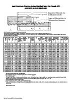
American National Standard pipe threads described in the following paragraphs provide taper and straight pipe threads for use in various combinations and with certain modifications to meet these specific needs. American National Standard Taper Pipe Threads.—The basic dimensions of the ANSI Standard taper pipe thread are given in Table 4. Form of Thread: The angle between the sides of the thread is 60 degrees when measured in an axial plane, and the line bisecting this angle is perpendicular to the axis. The depth of the truncated thread is based on factors entering into the manufacture of cutting tools and the making of tight joints and is given by the formulas in Table 4 or the data in Table 1 obtained from these formulas. Although the standard shows flat surfaces at the crest and root of the thread, some rounding may occur in commercial practice, and it is intended that the pipe threads of product shall be acceptable when crest and root of the tools or chasers lie within the limits shown in Table 1. Table 1. Limits on Crest and Root of American National Standard External and Internal Taper Pipe Threads, NPT ANSI/ASME B1.20.1-1983 (R1992) INTERNAL THREAD
Root
Max.h
Minimum Maximum Truncation Truncation Minimum Truncation
H
Crest
Maximum Truncation
Crest Crest
Minimum Maximum Minimum Truncation Truncation Truncation Maximum Truncation
Root
EXTERNAL THREAD Threads per Inch 27 18 14 111⁄2 8
Height of Sharp V Thread, H
Height of Pipe Thread, h
Truncation, f
Width of Flat, F, Equivalent toTruncation
Max.
Min.
Min.
Max.
Min.
Max.
0.03208 0.04811 0.06186 0.07531
0.02963 0.04444 0.05714 0.06957
0.02496 0.03833 0.05071 0.06261
0.0012 0.0018 0.0024 0.0029
0.0036 0.0049 0.0056 0.0063
0.0014 0.0021 0.0027 0.0033
0.0041 0.0057 0.0064 0.0073
0.10825
0.10000
0.09275
0.0041
0.0078
0.0048
0.0090
All dimensions are in inches and are given to four or five decimal places only to avoid errors in computations, not to indicate required precision.
Pitch Diameter Formulas: In the following formulas, which apply to the ANSI Standard taper pipe thread, E0 = pitch diameter at end of pipe; E1 = pitch diameter at the large end of the internal thread and at the gaging notch; D = outside diameter of pipe; L1 = length of hand-tight or normal engagement between external and internal threads; L2 = basic length of effective external taper thread; and p = pitch = 1 ÷ number of threads per inch. E 0 = D – ( 0.05D + 1.1 )p E 1 = E 0 + 0.0625L 1 Thread Length: The formula for L2 determines the length of the effective thread and includes approximately two usable threads that are slightly imperfect at the crest. The nor-
1848
AMERICAN PIPE THREADS
mal length of engagement, L1, between external and internal taper threads, when assembled by hand, is controlled by the use of the gages. L 2 = ( 0.80D + 6.8 )p Taper: The taper of the thread is 1 in 16, or 0.75 inch per foot, measured on the diameter and along the axis. The corresponding half-angle of taper or angle with the center line is 1 degree, 47 minutes. Tolerances on Thread Elements.—The maximum allowable variation in the commercial product (manufacturing tolerance) is one turn large or small from the basic dimensions. The permissible variations in thread elements on steel products and all pipe made of steel, wrought iron, or brass, exclusive of butt-weld pipe, are given in Table 2. This table is a guide for establishing the limits of the thread elements of taps, dies, and thread chasers. These limits may be required on product threads. On pipe fittings and valves (not steel) for steam pressures 300 pounds and below, it is intended that plug and ring gage practice as set up in the Standard ANSI B1.20.1 will provide for a satisfactory check of accumulated variations of taper, lead, and angle in such product. Therefore, no tolerances on thread elements have been established for this class. For service conditions where a more exact check is required, procedures have been developed by industry to supplement the regulation plug and ring method of gaging. Table 2. Tolerances on Taper, Lead, and Angle of Pipe Threads of Steel Products and All Pipe of Steel, Wrought Iron, or Brass ANSI B1.20-1983 (R1992) (Exclusive of Butt-Weld Pipe) Threads per Inch
Nominal Pipe Size
1,
1⁄ , 1⁄ 16 8 1⁄ , 3⁄ 4 8 1⁄ , 3⁄ 2 4 11⁄4, 11⁄2,
2
21⁄2 and larger
Taper on Pitch Line (3⁄4 in./ft)
Lead in Length of Effective Threads
60 Degree Angle of Threads, Degrees
Max.
Min.
27
+1⁄8
−1⁄16
±0.003
18
+1⁄8
−1⁄16
±0.003
± 21⁄2 ±2
14
+1⁄8
−1⁄16
±0.003a
±2
111⁄2 8
+1⁄8
−1⁄16
±0.003a
±11⁄2
+1⁄8
−1⁄16
±0.003a
±11⁄2
a The tolerance on lead shall be ± 0.003 in. per inch on any size threaded to an effective thread length
greater than 1 in. For tolerances on height of thread, see Table 1. The limits specified in this table are intended to serve as a guide for establishing limits of the thread elements of taps, dies, and thread chasers. These limits may be required on product threads.
Table 3. Internal Threads in Pipe Couplings, NPSC for Pressuretight Joints with Lubricant or Sealer ANSI/ASME B1.20.1-1983 (R1992) Nom.Pipe- Thds.per Size Inch 1⁄ 8 1⁄ 4 3⁄ 8 1⁄ 2 3⁄ 4
27 18 18 14
1
111⁄2 111⁄2
11⁄4
14
Minora Dia. Min. 0.340 0.442 0.577 0.715 0.925 1.161 1.506
Pitch Diameterb Min. Max. 0.3701 0.3771 0.4864 0.4968 0.6218 0.6322 0.7717 0.7851 0.9822 1.2305 1.5752
0.9956 1.2468 1.5915
Nom. Pipe
Thds. per Inch
11⁄2 2 21⁄2 3
111⁄2 111⁄2 8 8
Minora Dia. Min. 1.745 2.219 2.650 3.277
31⁄2 4 …
8 8 …
3.777 4.275 …
Pitch Diameterb Min. Max. 1.8142 1.8305 2.2881 2.3044 2.7504 2.7739 3.3768 3.4002 3.8771 4.3754 …
3.9005 4.3988 …
a As the ANSI Standard Pipe Thread form is maintained, the major and minor diameters of the internal thread vary with the pitch diameter. All dimensions are given in inches. b The actual pitch diameter of the straight tapped hole will be slightly smaller than the value given when gaged with a taper plug gage as called for in ANSI/ASME B1.20.1.
AMERICAN PIPE THREADS
1849
Table 4. Basic Dimensions, American National Standard Taper Pipe Threads, NPT ANSI/ASME B1.20.1-1983 (R1992) L2
L4
V
L5 L3
2p
Taper of Thread 1 in 16 Measured on Diameter
L1
E1 E5
E0
E3
Imperfect Threads due to Chamfer on die
E2
D
For all dimensions, see corresponding reference letter in table. Angle between sides of thread is 60 degrees. Taper of thread, on diameter, is 3⁄4 inch per foot. Angle of taper with center line is 1°47′. The basic maximum thread height, h, of the truncated thread is 0.8 × pitch of thread. The crest and root are truncated a minimum of 0.033 × pitch for all pitches. For maximum depth of truncation, see Table 1.
Nominal Pipe Size 1⁄ 16
Outside Dia. of Pipe, D
Threads per Inch, n
Pitch of Thread, p
Pitch Diameter at Beginning of External Thread, E0
Handtight Engagement Length,b L1
Effective Thread, Dia.,a E1
In.
Length,c L2
Dia., E2
In.
0.3125
27
0.03704
0.27118
0.160
0.28118
0.2611
0.28750
1⁄ 8
0.405
27
0.03704
0.36351
0.1615
0.37360
0.2639
0.38000
1⁄ 4
0.540
18
0.05556
0.47739
0.2278
0.49163
0.4018
0.50250
3⁄ 8
0.675
18
0.05556
0.61201
0.240
0.62701
0.4078
0.63750
1⁄ 2
0.840
14
0.07143
0.75843
0.320
0.77843
0.5337
0.79179
3⁄ 4
1.050
14
0.07143
0.96768
0.339
0.98887
0.5457
1.00179
1
1.315
111⁄2
0.08696
1.21363
0.400
1.23863
0.6828
1.25630
11⁄4
1.660
111⁄2
0.08696
1.55713
0.420
1.58338
0.7068
1.60130
11⁄2
1.900
111⁄2
0.08696
1.79609
0.420
1.82234
0.7235
1.84130
2
2.375
111⁄2
0.08696
2.26902
0.436
2.29627
0.7565
2.31630
21⁄2
2.875
8
0.12500
2.71953
0.682
2.76216
1.1375
2.79062
3
3.500
8
0.12500
3.34062
0.766
3.38850
1.2000
3.41562
31⁄2
4.000
8
0.12500
3.83750
0.821
3.88881
1.2500
3.91562
4
4.500
8
0.12500
4.33438
0.844
4.38712
1.3000
4.41562
5
5.563
8
0.12500
5.39073
0.937
5.44929
1.4063
5.47862
6
6.625
8
0.12500
6.44609
0.958
6.50597
1.5125
6.54062
8
8.625
8
0.12500
8.43359
1.063
8.50003
1.7125
8.54062
10
10.750
8
0.12500
10.54531
1.210
10.62094
1.9250
10.66562
12
12.750
8
0.12500
12.53281
1.360
12.61781
2.1250
12.66562
14 OD
14.000
8
0.12500
13.77500
1.562
13.87262
2.2500
13.91562
16 OD
16.000
8
0.12500
15.76250
1.812
15.87575
2.4500
15.91562
18 OD
18.000
8
0.12500
17.75000
2.000
17.87500
2.6500
17.91562
20 OD
20.000
8
0.12500
19.73750
2.125
19.87031
2.8500
19.91562
24 OD
24.000
8
0.12500
23.71250
2.375
23.86094
3.2500
23.91562
a Also pitch diameter at gaging notch (handtight plane). b Also length of thin ring gage and length from gaging notch to small end of plug gage. c Also length of plug gage.
1850
AMERICAN PIPE THREADS
Table 5. Basic Dimensions, American National Standard Taper Pipe Threads, NPT ANSI/ASME B1.20.1-1983 (R1992) Nominal Pipe Size 1⁄ 16 1⁄ 8 1⁄ 4 3⁄ 8 1⁄ 2 3⁄ 4
1 11⁄4 11⁄2 2 21⁄2 3 31⁄2 4 5 6 8 10 12 14 OD 16 OD 18 OD 20 OD 24 OD
Wrench Makeup Length for Internal Thread Length,c L3
Dia., E3
Vanish Thread, (3.47 thds.), V
Nominal Perfect External Threadsa
Overall Length External Thread, L4
Length, L5
Dia., E5
Height of Thread, h
Basic Minor Dia. at Small End of Pipe,b K0
0.1111 0.1111 0.1667 0.1667
0.26424 0.35656 0.46697 0.60160
0.1285 0.1285 0.1928 0.1928
0.3896 0.3924 0.5946 0.6006
0.1870 0.1898 0.2907 0.2967
0.28287 0.37537 0.49556 0.63056
0.02963 0.02963 0.04444 0.04444
0.2416 0.3339 0.4329 0.5676
0.2143 0.2143 0.2609 0.2609 0.2609
0.74504 0.95429 1.19733 1.54083 1.77978
0.2478 0.2478 0.3017 0.3017 0.3017
0.7815 0.7935 0.9845 1.0085 1.0252
0.3909 0.4029 0.5089 0.5329 0.5496
0.78286 0.99286 1.24543 1.59043 1.83043
0.05714 0.05714 0.06957 0.06957 0.06957
0.7013 0.9105 1.1441 1.4876 1.7265
0.2609 0.2500d 0.2500d 0.2500 0.2500 0.2500 0.2500 0.2500 0.2500 0.2500 0.2500 0.2500 0.2500 0.2500 0.2500
2.25272 2.70391 3.32500 3.82188 4.31875 5.37511 6.43047 8.41797 10.52969 12.51719 13.75938 15.74688 17.73438 19.72188 23.69688
0.3017 0.4337 0.4337 0.4337 0.4337 0.4337 0.4337 0.4337 0.4337 0.4337 0.4337 0.4337 0.4337 0.4337 0.4337
1.0582 1.5712 1.6337 1.6837 1.7337 1.8400 1.9462 2.1462 2.3587 2.5587 2.6837 2.8837 3.0837 3.2837 3.6837
0.5826 0.8875 0.9500 1.0000 1.0500 1.1563 1.2625 1.4625 1.6750 1.8750 2.0000 2.2000 2.4000 2.6000 3.0000
2.30543 2.77500 3.40000 3.90000 4.40000 5.46300 6.52500 8.52500 10.65000 12.65000 13.90000 15.90000 17.90000 19.90000 23.90000
0.06957 0.100000 0.100000 0.100000 0.100000 0.100000 0.100000 0.100000 0.100000 0.100000 0.100000 0.100000 0.100000 0.100000 0.100000
2.1995 2.6195 3.2406 3.7375 4.2344 5.2907 6.3461 8.3336 10.4453 12.4328 13.6750 15.6625 17.6500 19.6375 23.6125
a The length L from the end of the pipe determines the plane beyond which the thread form is imper5 fect at the crest. The next two threads are perfect at the root. At this plane the cone formed by the crests of the thread intersects the cylinder forming the external surface of the pipe. L5 = L2 − 2p. b Given as information for use in selecting tap drills. c Three threads for 2-inch size and smaller; two threads for larger sizes. d Military Specification MIL—P—7105 gives the wrench makeup as three threads for 3 in. and smaller. The E3 dimensions are then as follows: Size 21⁄2 in., 2.69609 and size 3 in., 3.31719. All dimensions given in inches.
Increase in diameter per thread is equal to 0.0625/n. The basic dimensions of the ANSI Standard Taper Pipe Thread are given in inches to four or five decimal places. While this implies a greater degree of precision than is ordinarily attained, these dimensions are the basis of gage dimensions and are so expressed for the purpose of eliminating errors in computations.
Engagement Between External and Internal Taper Threads.—The normal length of engagement between external and internal taper threads when screwed together handtight is shown as L1 in Table 4. This length is controlled by the construction and use of the pipe thread gages. It is recognized that in special applications, such as flanges for high-pressure work, longer thread engagement is used, in which case the pitch diameter E1 (Table 4) is maintained and the pitch diameter E0 at the end of the pipe is proportionately smaller. Railing Joint Taper Pipe Threads, NPTR.—Railing joints require a rigid mechanical thread joint with external and internal taper threads. The external thread is basically the same as the ANSI Standard Taper Pipe Thread, except that sizes 1⁄2 through 2 inches are shortened by 3 threads and sizes 21⁄2 through 4 inches are shortened by 4 threads to permit the use of the larger end of the pipe thread. A recess in the fitting covers the last scratch or imperfect threads on the pipe.
AMERICAN PIPE THREADS
1851
Straight Pipe Threads in Pipe Couplings, NPSC.—Threads in pipe couplings made in accordance with the ANSI B1.20.1 specifications are straight (parallel) threads of the same thread form as the ANSI Standard Taper Pipe Thread. They are used to form pressuretight joints when assembled with an ANSI Standard external taper pipe thread and made up with lubricant or sealant. These joints are recommended for comparatively low pressures only. Straight Pipe Threads for Mechanical Joints, NPSM, NPSL, and NPSH.—W h i l e external and internal taper pipe threads are recommended for pipe joints in practically every service, there are mechanical joints where straight pipe threads are used to advantage. Three types covered by ANSI B1.20.1 are: Free-Fitting Mechanical Joints for Fixtures (External and Internal), NPSM: Standa rd iron, steel, and brass pipe are often used for special applications where there are no internal pressures. Where straight thread joints are required for mechanical assemblies, straight pipe threads are often found more suitable or convenient. Dimensions of these threads are given in Table 6. Table 6. American National Standard Straight Pipe Threads for Mechanical Joints, NPSM and NPSL ANSI/ASME B1.20.1-1983 (R1992) Nominal Pipe Size 1⁄ 8 1⁄ 4 3⁄ 8 1⁄ 2 3⁄ 4
1 11⁄4 11⁄2 2 21⁄2 3 31⁄2 4 5 6 1⁄ 8 1⁄ 4 3⁄ 8 1⁄ 2 3⁄ 4
1 11⁄4 11⁄2 2 21⁄2 3 31⁄2 4 5 6 8 10 12
Threads per Inch 27 18 18 14 14 111⁄2 111⁄2 111⁄2 111⁄2 8 8 8 8 8 8 27 18 18 14 14 111⁄2 111⁄2 111⁄2 111⁄2 8 8 8 8 8 8 8 8 8
External Thread Major Diameter Pitch Diameter Allowance
Max.a
Internal Thread Minor Diameter Pitch Diameter
Min. Max. Min. Min.a Free-fitting Mechanical Joints for Fixtures—NPSM
Max.
0.0011 0.397 0.390 0.3725 0.3689 0.358 0.364 0.0013 0.526 0.517 0.4903 0.4859 0.468 0.481 0.0014 0.662 0.653 0.6256 0.6211 0.603 0.612 0.0015 0.823 0.813 0.7769 0.7718 0.747 0.759 0.0016 1.034 1.024 0.9873 0.9820 0.958 0.970 0.0017 1.293 1.281 1.2369 1.2311 1.201 1.211 0.0018 1.638 1.626 1.5816 1.5756 1.546 1.555 0.0018 1.877 1.865 1.8205 1.8144 1.785 1.794 0.0019 2.351 2.339 2.2944 2.2882 2.259 2.268 0.0022 2.841 2.826 2.7600 2.7526 2.708 2.727 0.0023 3.467 3.452 3.3862 3.3786 3.334 3.353 0.0023 3.968 3.953 3.8865 3.8788 3.835 3.848 0.0023 4.466 4.451 4.3848 4.3771 4.333 4.346 0.0024 5.528 5.513 5.4469 5.4390 5.395 5.408 0.0024 6.585 6.570 6.5036 6.4955 6.452 6.464 Loose-fitting Mechanical Joints for Locknut Connections—NPSL … 0.409 … 0.3840 0.3805 0.362 … … 0.541 … 0.5038 0.4986 0.470 … … 0.678 … 0.6409 0.6357 0.607 … … 0.844 … 0.7963 0.7896 0.753 … … 1.054 … 1.0067 1.0000 0.964 … … 1.318 … 1.2604 1.2523 1.208 … … 1.663 … 1.6051 1.5970 1.553 … … 1.902 … 1.8441 1.8360 1.792 … … 2.376 … 2.3180 2.3099 2.265 … … 2.877 … 2.7934 2.7817 2.718 … … 3.503 … 3.4198 3.4081 3.344 … … 4.003 … 3.9201 3.9084 3.845 … … 4.502 … 4.4184 4.4067 4.343 … … 5.564 … 5.4805 5.4688 5.405 … … 6.620 … 6.5372 6.5255 6.462 … … 8.615 … 8.5313 8.5196 8.456 … … 10.735 … 10.6522 10.6405 10.577 … … 12.732 … 12.6491 12.6374 12.574 …
Min.b
Max.
0.3736 0.4916 0.6270 0.7784 0.9889 1.2386 1.5834 1.8223 2.2963 2.7622 3.3885 3.8888 4.3871 5.4493 6.5060
0.3783 0.4974 0.6329 0.7851 0.9958 1.2462 1.5912 1.8302 2.3044 2.7720 3.3984 3.8988 4.3971 5.4598 6.5165
0.3863 0.5073 0.6444 0.8008 1.0112 1.2658 1.6106 1.8495 2.3234 2.8012 3.4276 3.9279 4.4262 5.4884 6.5450 8.5391 10.6600 12.6569
0.3898 0.5125 0.6496 0.8075 1.0179 1.2739 1.6187 1.8576 2.3315 2.8129 3.4393 3.9396 4.4379 5.5001 6.5567 8.5508 10.6717 12.6686