![Partsbook LS4-2000 - PA0426 [PDF]](https://pdfs.asia/img/200x200/partsbook-ls4-2000-pa0426.jpg)
5 0 6 MB
PRODUCT MANUAL TOWER LIGHT LS4-2000 PA0426 Series Revisi 0
Thank You You trust us as your choice to be
Solution for your productivity We hope our products and services make you satisfied
Procedure for use This book is used as an operating guide, maintenance, and repair product produced by PT United Tractors Pandu Engineering. Always use the OEM components and parts in this book as parts for your product to guarantee product performance and durability.
Please pay attention to the compatibility of your product with the OMM & Parts Book version by looking at the serial number of your product with the description di bawah.
Edition November 2019
Revision Code Revisi 0
Product Series PA0426
Product Serial Number PA0426-1911111
How to use This book
1
2
3
1. Product Type
2. Product Series 3. Product Revision 4. Publishing Edition 5. Product Serial Number that is in accordance with this book
6
4
3
5
2
How to search Your Product Serial Number
Your product serial number can be found in the circled section of your product.. Make sure you use the correct OMM & Parts manual that matches your product serial number.
Examples of product serial number plates
7
Parts & Components Guidance
How to use Parts & Components Guide 6
1
2
3
4
5
7
11
8
12
1.
Book Page Number
8.
Description
2.
Image Title
9.
Quantity
3.
Picture
10.
Remarks
4.
Ballon Part
11.
Image Page (Section/Total)
5.
Image Page (Section/Total)
12.
Image Title
6.
Part Number Image
13.
Book Page Number
7.
Part Number
10
9
10
13
Ordering Guide Parts & Components All PATRIA products have identification in the form of a product serial number. To ensure the parts & components that you order are compatible with your product, Please always include product identification when ordering as an example below :
After you have included the spare parts that you want to order, please contact us at
PT UNITED TRACTORS PANDU ENGINEERING Part & Service Division
Product Type *
Jl. Jababeka XI, Blok H30-40
Unit Serial Number *
Kawasan Industri Jababeka, Cikarang, Bekasi, Jawa Barat, Indonesia
Part Number ( poin 7)
Telepon: (021) 8935016, 8935017, 8935018, 8936353 ext 1124
Description (poin 8) Quantity (poin 9)
Fax: (021) 8934772 Example of writing when ordering : Product Type
: TOWER LAMP LS4-2000
Product Series
: PA0426
Part Number
: B-1620-12032
Description
: WASHER PLATE
Quantity
: 1 pcs
* See page 5
11
Operation & Maintenance Manual Safety
PREFACE
SAFETY
This guidance book has to be kept by the operator and be read carefully to have deep understanding
Before starting operating or maintaining, operator or maintenance which have been assigned have to read this guidance book precisely.
This guidance book is about how to operate in properly, to maintain easily and how to maintain Unit in routinely Before operating the Unit, please read this book precisely in order to operate safely This book could be inappropriate with the actual condition due to our product development In case of borrowing or moving any unit, thus this book should be included In case of having question, please do not hesitate to consult with our Sales Department in our Company Procedures and warnings which stated in this guidance book are only valid for using specifically assigned machines. You have to ensure the activity is safe for you and others. In case of damage book or obsolete, You have to re-order this book to our Library
Stated procedures and warnings in this book are only for special assigned machine users. In case of using for other necessity which is not specifically prohibited, you have to sure the job is safe for you and others. Some actions in operation or maintenance of machinery or equipment could result any serious accident if not done in appropriate ways according to explanation described by this guidance book.
GENERAL -
Always observe prohibitions or rules about working procedures within the working area
-
Always perform checks before starting and periodic maintaining. DO NOT operate until you have checked its condition
WHO HAVE TO READ THIS GUIDANCE BOOK All the people who will operate and routinely maintain, suggested to read this guidance book precisely Guidance which stated in this book is application which usually done by person who operate and maintain machine routinely
-
Wear safety helmets, safety glasses and safety shoes whenever necessary. Never operate with wet or oily hands
-
Take care of your health. Do not drive when tired, or after drinking liquor
-
Consider the laws and regulations that apply when it comes to dispose any dangerous things (oil, fuels, solvents, filters, batteries)
SAFETY
Safety problem is always be your main duty and responsibility. Study “About Safety” included safety procedures and warnings in using unit. But, preventive actions due to explanation of safety below, could also be used for other units with specification or special additional equipment.
14
SAFETY
SAFETY INFORMATION
SAFETY LABELS
To enable you to use this machine safely, safety precaution and labels are given in this manual and affixed to the machine to give explanations of situations involving potential hazards and of the methods of avoiding such situation
The following warning signs and safety labels are used on this machine. -
Be sure that you fully understand the correct position and content of labels.
-
To ensure that the content of labels can be read properly, be sure that they are in the correct place and always keep them clean. When cleaning them, do not use organic solvents or gasoline. These may cause the labels to peel off.
-
There are also other labels in addition to the warning signs and safety labels. Handle those labels in the same way.
-
If the labels are damaged, lost, or cannot be read properly, replace them with new ones. For details of the part numbers for the labels, see this manual or the actual label, and place an order with manufacturer or distributor.
SIGNAL WORDS The following signal word are used to inform you that is a potential hazardous situation that may lead to personal injury or damage. In this manual and on machine labels, the following signal words are used to express the potential level of hazard.
INDICATES A HAZARDOUS SITUATION WHICH , IF NOT AVOIDED, WILL RESULT IN DEATH OR SERIOUS INJURY
Indicates a hazardous situation which, if not avoided, could result in death or serious injury.
Indicates a hazardous situation which, if not avoided, could result in minor or moderate injury.
SAFETY
15
LIST OF SAFETY LABELS ON EQUIPMENT
LIST OF SAFETY LABELS ON EQUIPMENT
OLT06S0001A
OLT06S0005A
OPERATING INSTRUCTIONS
ELECTRICAL SHOCK DANGER
Sticker gives basic information on starting stopping and daily engine check.
Sticker warns about potential electrical shock. Always deploy the outriggers before using the machine. Touch or operate with great care
OLT06S0002A TRAILER SETUP Sticker gives basic information setting up the trailer for hitching to the tow vehicle and unhitching from the tow vehicle
16
OLT06S0006A ELECTRICAL SHOCK FROM ELECTRICAL LINES ABOVE Sticker warns about potential electrical shock if mast is raised into overhead electrical lines. Always park machine away from electrical lines.
SAFETY
LIST OF SAFETY LABELS ON EQUIPMENT
LIST OF SAFETY LABELS ON EQUIPMENT
OLT06S0007A
OLT06S0009A
ALWAYS OPERATE MACHINE AFTER READING MANUAL
TILT OVER HAZARD IF OUTRIGGERS NOT DEPLOYED
Sticker cautions operator to read the manual and familiarise themselves with the machine before operating it.
Sticker cautions against raising the mast and operating the machine without deploying the outriggers fully.
OLT06S0008A
OLT06S0010A
ROLL OVER HAZARD IF TOWED AT VERY HIGH SPEEDS
LOWER MAST BEFORE TOWING/MOVING MACHINE
Sticker cautions against towing the vehicle at very high speeds or taking sharp turns at high speeds as it may cause the machine to roll over
Sticker cautions against moving the machine before lowering the tower and tilting the light arm.
SAFETY
17
LIST OF SAFETY LABELS ON EQUIPMENT
LIST OF SAFETY LABELS ON EQUIPMENT
OLT06S0012A
OLT06S0014A-L/R
LOCATION OF DIESEL TANK FILLER
CAUTION AGAINST PRESSURE WASH OF INDICATED AREAS
Sticker indicates the location of the diesel tank filler located inside the canopy at the front side.
Sticker cautions the user to avoid using pressurised water to clean indicated areas as it may cause damage or water ingress.
OLT06S0013A CAUTION FOR OUTFLOW OF VERY HOT AIR Sticker cautions the user to stay away or avoid blocking vents where hot air exits to protect from burns and engine damage. OLT06S0015A GROUNDING THROUGH OUTRIGGER Sticker informs that electrical grounding of the machine occurs through the outrigger and hence outriggers must be fully deployed during use of the machine to avoid potential shocks.
18
SAFETY
LIST OF SAFETY LABELS ON EQUIPMENT
LIST OF SAFETY LABELS ON EQUIPMENT
OLT06S0016A
OLT06S0019A
TIE DOWN AND LIFTING HOOK
HOT SURFACE
Sticker informs the location of the tie down/lifting hook. Machine should only be tied down or lifted up using the provided hooks.
Sticker cautions operator against touching indicated areas as they might be hot during engine operations and make cause burns.
OLT06S0017A
OLT06S0020A
CAUTION AGAINST BLOCKING COOL AIR INLET VENTS
PINCH POINT
Sticker cautions the user to avoid blocking vents where cool air is drawn into the canopy for the engine as that might damage the engine or cause overheating.
Sticker warns against putting fingers in indicated areas as they might be caught or pinched during operation and causing serious injury.
SAFETY
19
LIST OF SAFETY LABELS ON EQUIPMENT
LIST OF SAFETY LABELS ON EQUIPMENT
OLT06S0022A
OLT06S0024A
MAST ROTATION TO BE LOCKED
ELECTRICAL TERMINATIONS IN PANEL
Sticker advises users to lock the mast rotation before operating or moving the tower.
Sticker gives the wire numbers and termination in the electrical panel for ease of fault tracing.
OLT06S0023A
FORKLIFT POCKET LOCATION Sticker shows the location of the forklift pockets. Machine is to be lifted by a forklift using the denoted locations only. Always exercise great care when using the forklift pockets and ensure the machine is well supported on the tines before lifting.
20
OLT06S0025A ENGINE OIL DRAIN PLUG LOCATION Sticker indicates the location of the oil drain plug and the required wrench for unscrewing the drain plug.
SAFETY
LIST OF SAFETY LABELS ON EQUIPMENT
OLT06S0029A MAINTENANCE INSTRUCTIONS Sticker gives information on daily maintenance to be carried out on machine. Please check manual for more details.
GENERAL PRECAUTIONS COMMON TO OPERATION AND MAINTENANCE Mistakes in operation, inspection, or maintenance may result in serious personal injury or death. Before carrying out operation, inspection, or maintenance, always read this manual and the safety labels on the machine carefully and obey the warnings.
PRECAUTIONS BEFORE STARTING OPERATING ENSURING SAFE OPERATION -
Only trained and authorized personnel can operate and maintain the machine.
-
Follow all safety, precautions, and instructions in this manual when operating or performing inspection or maintenance on the machine.
-
If you are not feeling well, or if you are under the influence of alcohol or medication, your ability to safely operate or repair your machine may be severely impaired, putting yourself and everyone else on your job site in danger.
-
When working with another operator or with the person on the worksite traffic duty, discuss the content of the operation beforehand and use the determined signals when carrying out the operation.
UNDERSTANDING THE MACHINE Before operating the machine, read this manual thoroughly. If there are any places in this manual that you do not understand, ask the person in charge of safety to give an explanation.
SAFETY
21
GENERAL PRECAUTIONS COMMON TO OPERATION AND MAINTENANCE
GENERAL PRECAUTIONS COMMON TO OPERATION AND MAINTENANCE
PRECAUTIONS REGARDING SAFETY-RELATED EQUIPMENT
WEAR WELL-FITTING CLOTHES AND PROTECTIVE EQUIPMENT
-
Be sure that all guards, covers and mirrors are in their proper position. Have guards and covers repaired immediately, if they are damaged.
-
-
Understand the method of use of safety features and use them properly.
-
Never remove any safety features. Always keep them in good operating condition.
Check that all protective equipments function properly before using it.
INSPECTING MACHINE Check the machine before starting operations. If any abnormality is found, do not operate the machine until repairs of the problem location have been completed. KEEP MACHINE CLEAN -
If you get on or off the machine or carry out inspection and maintenance when the machine is dirty with mud or oil, there is a hazard that you will slip and fall. Wipe off any mud or oil from the machine. Always keep the machine clean.
-
If water gets into the electrical system, there is a hazard that it will cause malfunctions which may cause injury or even death. When washing the machine with water or steam, do not allow the water or steam to come into direct contact with electrical components
WEAR WELL-FITTING CLOTHES AND PROTECTIVE EQUIPMENT -
Do not wear loose clothes or any accessories. If these catch on the control levers or protruding parts, there is danger that it may cause the machine to move unexpectedly.
-
Always wear a hard hat and safety shoes. If the nature of the work requires it, wear safety glasses, mask, gloves, ear plugs, and safety belt when operating or maintaining the machine.
-
If you have long hair and it hangs out from your hard hat, there is a hazard that it may get caught up in the machine, so tie your hair up and be careful not to let it get caught.
22
SAFETY
GENERAL PRECAUTIONS COMMON TO OPERATION AND MAINTENANCE
GENERAL PRECAUTIONS COMMON TO OPERATION AND MAINTENANCE
PROVIDE FIRE EXTINGUISHER AND FIRST AID KIT
FIRE PREVENTION
Always follow the precautions below to prepare for action if any injury or fire should occur.
ACTION IF FIRE OCCURS
-
Be sure that fire extinguishers have been provided and read the labels to ensure that you know how to use them in emergencies.
-
Carry out periodic inspection and maintenance to ensure that the fire extinguisher can always be used.
-
Provide a first aid kit in the storage point. Carry out periodic checks and add to the contents if necessary.
-
Press the emergency button to stop the engine
PRECAUTIONS TO PREVENT FIRE -
Fire cause by fuel or oil. Do not bring any flame or fire close to flammable substances such as fuel or oil. There is danger that they may catch fire. To prevent fire, always observe the following: -
Do not smoke or use any flame near fuel or other flammable substances.
-
Stop the engine before adding fuel.
-
Do not leave the machine when adding fuel or oil.
-
Tighten all fuel and oil caps securely.
-
After adding fuel or oil, wipe up any spilled fuel or oil.
-
Do not weld or use a cutting torch to cut any pipes or tubes that contain flammable liquids.
IF ANY PROBLEM IS FOUND If you find any problems in the machine during operation or maintenance (noise, vibration, smell, incorrect gauges, smoke, oil leakage, etc., or any abnormal display on the warning devices or monitor), report to the person in charge and have the necessary action taken. Do not operate the machine until the problem has been corrected.
SAFETY
23
GENERAL PRECAUTIONS COMMON TO OPERATION AND MAINTENANCE
GENERAL PRECAUTIONS COMMON TO OPERATION AND MAINTENANCE
PRECAUTION TO PREVENT FIRE
UNAUTHORIZED MODIFICATION
-
Fire caused by accumulation of flammable material
-
Remove any dry leaves, chips, pieces of paper, coal dust, or any other flammable materials accumulated or affixed around the engine, exhaust manifold, muffler, or battery, or inside the undercover.
Manufacturer will not be responsible for any injuries, accidents, product failures or other property damages resulting from modifications made without authorization from Manufacturer.
-
Any modification made without authorization from Manufacturer can create hazards. Before making a modification, consult your Manufacturer distributor.
-
If modification made without authorization, manufacturer will not provide the warranty of this machine.
-
Fire coming from electric wiring Short circuits in the electrical system can cause fire. To prevent fire, always observe the following. -
Keep all electric wiring connections clean and securely tightened.
-
Check the wiring every day for looseness or damage. Tighten any loose connectors or wiring clamps. Repair or replace any damaged wiring.
-
Fire coming from piping Check that all the hose and tube clamps, guards, and cushions are securely fixed in position.
PRECAUTIONS WHEN RUNNING ENGINE INSIDE BUILDING The engine exhaust gas contains substances that may damage your health or even cause death. Start or operate the engine in a place where there is good ventilation. If the engine or machine must be operated inside a building or under ground, where the ventilation is poor, take steps to ensure that the engine exhaust gas is removed and that ample fresh air is brought in.
If they are loose, they may vibrate during operation and rub against other parts. There is danger that this may lead to damage to the hoses and cause high- pressure oil to spurt out, leading to fire, serious personal injury or death. -
Explosion caused by lightning equipment When checking fuel, oil, battery electrolyte, or coolant, always use lighting with anti-explosion specifications.
24
SAFETY
PRECAUTIONS FOR OPERATION
PRECAUTIONS FOR OPERATION
PRECAUTION FOR JOBSITE
PRECAUTION FOR JOBSITE
INVESTIGATE AND CONFIRM JOBSITE CONDITION
DO NOT GO CLOSE TO HIGH-VOLTAGE CABLES
On the jobsite, there are various hidden dangers that may lead to personal injury or death. Before starting operations, always check the following to confirm that there is no danger on the jobsite.
Do not travel or operate the machine near electric cables. There is a hazard of electric shock, which may cause serious personal injury or death. On jobsites where the machine may go close to electric cables, always do as follows.
-
-
Before starting work near electric cables, inform the local power company of the work to be performed, and ask them to take the necessary action.
-
When carrying out operations near high voltage cables, do not let anyone near the machine.
Check the terrain and condition of the ground at the worksite, and determine the safest method of operation. Do not operate where there is a hazard of landslides or falling rocks.
-
Take necessary measures to prevent any unauthorized person from entering the operating area.
-
When traveling or operating in water or on soft ground, check the water depth, speed of the current, bedrock, and shape of the ground beforehand and avoid any place that will obstruct travel.
-
Maintain the travel path on the jobsite so that there is no obstruction to travel operations.
WORKING ON LOOSE GROUND Avoid traveling or operating your machine too close to the edge of cliffs, overhangs, and deep ditches. The ground may be weak in such areas. If the ground should collapse under the weight or vibration of the machine, there is a hazard that the machine may fall or tip over. Remember that the soil after heavy rain or blasting or after earthquakes is weak in these areas.
SAFETY
25
PRECAUTIONS FOR OPERATION
PRECAUTIONS FOR OPERATION
STARTING ENGINE
STARTING ENGINE
USE WARNING TAGS
PRECAUTIONS WHEN STARTING ENGINE
If there is any "DANGER! Do Not operate!" warning tag displayed, it means that someone is carrying out inspection and maintenance of the machine. If the warning sign is ignored and the machine is operated, there is danger that the person carrying out inspection or maintenance may be caught in the rotating parts or moving parts and suffer serious personal injury or death. Do not start the engine or touch the levers.
Do not attempt to start the engine by short-circuiting the engine starting circuit. This may cause fire, serious personal injury or death.
PRECAUTIONS IN COLD AREAS -
Carry out the warming-up operation thoroughly. If the machine is not thoroughly warmed up before the control are operated, the reaction of the machine will be slow, and this may lead to unexpected accidents.
-
If the battery electrolyte is frozen, do not charge the battery or start the engine with a different power source. There is a hazard that this will ignite the battery and cause the battery to explode. Before charging or starting the engine with a different power source, melt the battery electrolyte and check that there is no leakage of electrolyte before starting.
STARTING WITH BOOSTER CABLES CHECK BEFORE STARTING ENGINE Carry out the following checks before starting the engine at the beginning of the day's work to ensure that there is no problem with the operation of the machine. If this inspection is not carried out properly problems may occur with the operation of the machine, and there is danger that this may lead to serious personal injury or death.
-
Check the fuel level, and oil level in engine oil pan, check for clogging of the air cleaner, and check for damage to the electric wiring.
-
Check the bracket lamp and make sure that bracket lamp is locked.
26
If any mistake is made in the method of connecting the booster cables, it may cause the battery to explode, so always do as follows. -
Always wear safety goggles and rubber gloves when starting the engine with booster cable.
-
When connecting a normal machine to a problem machine with booster cables, always use a normal machine with the same battery voltage as the problem machine.
SAFETY
PRECAUTIONS FOR OPERATION
PRECAUTIONS FOR OPERATION
STARTING ENGINE
TRANSPORTATION
STARTING WITH BOOSTER CABLES
SAFETY BEFORE TRANSPORTATION
-
When starting from another machine, do not allow the two machines to touch.
-
-
When connecting the booster cables, turn the starting switch to the OFF position for both the normal machine and problem machine. There is a hazard that the machine will move when the power is connected.
Make sure that all lamp are facing down, and spring lock pin bracket lamp insert to the hole pin, make sure it’s locked.
-
Make sure that all cabin doors are locked.
-
Visual check condition of tires, axle, suspension and tire pressure.
-
-
Be sure to connect the positive (+) cable first when installing the booster cables. Disconnect the negative (-) cable (ground side) first when removing them. When removing the booster cables, be careful not to let the booster cable clips touch each other or to let the clips touch the machine.
SAFETY
- check tire pressure - check for loosen bolts or nuts -
Hook up draw-bar to towing ball and make sure that it’s locked
-
Plug-in trailer 7-pin connector.
-
Break-away cable hooked-up with the towing vehicle.
-
Fully retract jockey wheel and take-off handbrake.
27
PRECAUTIONS FOR MAINTENANCE PRECAUTION BEFORE MAINTENANCE DISPLAY WARNING MAINTENANCE
STARTING
TAG
DURING
PRECAUTIONS FOR MAINTENANCE INSPECTION
INSPECTION
&
AND
If there is any "DANGER! Do NOT operate!" warning tag displayed, it means that someone is carrying out inspection and maintenance of the machine. If the warning sign is ignored and the machine is operated, there is danger that the person carrying out inspection or maintenance may be caught in the rotating parts or moving parts and suffer serious personal injury or death. Do not start the engine or touch the control.
PRECAUTION BEFORE MAINTENANCE
STARTING
INSPECTION
&
ONLY AUTHORIZED PERSONNEL Do not allow any unauthorized personnel into the area when servicing the machine. If necessary, employ a guard.
APPOINT SUPERVISOR WHEN WORKING WITH OTHERS When repairing the machine or when removing and installing the work equipment, appoint a supervisor and follow his instructions during the operation.
- If necessary, put up signs around the machine also.
STOP ENGINE BEFORE CARRYING OUT INSPECTION & MAINTENANCE
When not using this warning tag, keep it in the toolbox.
-
If there is no toolbox, keep it in the pocket for the Operation and Maintenance Manual
Always stop the machine before performing any inspection and maintenance.
-
Put blocks / wheelchoke in front of and behind the tires to prevent the machine from moving.
KEEP WORKPLACE CLEAN AND TIDY Do not leave hammers or other tools lying around in the work place. Wipe up all grease, oil, or other substances that will cause you to slip. Always keep the work place clean the tidy to enable you to carry out operations safely. If the work place is not kept clean and tidy, there is the danger that you will trip, slip, or fall over and injure yourself.
SELECT SUITABLE MAINTENANCE
PLACE
FOR
INSPECTION
PROPER TOOLS Use only tools suited to the task and be sure to use the tools correctly. Using damaged, deformed, or low quality tools, or making improper use of the tools may cause serious personal injury.
AND
- Stop the machine on firm, level ground. - Select a place where there is no hazard of landslides, falling rocks, or flooding.
28
SAFETY
PRECAUTIONS FOR MAINTENANCE
PRECAUTIONS FOR MAINTENANCE
PRECAUTION FOR INSPECTION & MAINTENANCE
PRECAUTION FOR INSPECTION & MAINTENANCE
PRECAUTION WHEN WELDING
HANDLING BATTERY
Welding operations must always be carried out by a qualified welder and in a place equipped with proper equipment. There is a hazard of gas, fire, or electrocution when carrying out welding, so never allow any unqualified personnel to carry out welding.
-
Danger from dilute sulfuric acid When the battery is being charged, flammable hydrogen gas is generated and may explode. In addition, the battery electrolyte includes dilute sulfuric acid. Any mistake in handling may cause serious personal injury, explosion, or fire, so always observe the following.
HANDLING BATTERY
-
Before inspecting or handling the battery, turn the key in the starting switch to the OFF position.
When handling the battery, always wear protective goggles and rubber gloves.
-
If battery electrolyte gets into your eyes, immediately wash your eyes with large amounts of fresh water. After that, get medical attention immediately.
-
If battery electrolyte gets on your clothes or skin, wash it off immediately with large amounts of water.
-
Danger of battery exploding When the battery is being charged, flammable hydrogen gas is generated and may explode. In addition, the battery electrolyte includes dilute sulfuric acid. Any mistake in handling may cause serious personal injury, explosion, or fire, so always observe the following. -
Do not use or charge the battery if the battery electrolyte is below the LOWER LEVEL mark. This will cause explosion. Always carry out periodic inspection of the battery electrolyte level, and add distilled water (or commercially available battery filler solution) to the UPPER LEVEL mark.
-
Do not smoke or bring any flame close to the battery.
-
After charging, tighten the battery caps securely.
-
Removing battery cables
Before repairing the electrical system turn the starting switch OFF. Then turn the battery isolator switch to “OFF” position. Wait for approx. 1 minute, then remove the negative (-) battery cable to stop the flow of electricity.
SAFETY
29
PRECAUTIONS FOR MAINTENANCE
PRECAUTIONS FOR MAINTENANCE
PRECAUTION FOR INSPECTION & MAINTENANCE
PRECAUTION FOR INSPECTION & MAINTENANCE
-
Danger of sparks
PRECAUTION WITH MOVING PARTS ENGINE FAN & BELT
There is hazard that sparks will be generated, so always observe the following.
WARNING! FAN AND BELT
-
Do not let tools or other metal objects make any contact between the battery cables. Do not leave tools lying around near the battery.
-
When removing the battery cables, remove the ground cable (negative (-) cable) first. When installing, connect the positive (+) cable first, then connect the ground.
-
Tighten the battery cable terminals securely
-
Secure the battery firmly in the specified position.
-
Very dangerous if you or other devices on or hit the fan or fan belt while fan is moving. Do not ever touch the fan while moving.
-
Always turn the engine off while inspecting around spinning area,
-
While inspecting around spinning area, do not ever let anything get close. It could cause anything trapped.
PRECAUTIONS WHEN USING HAMMER When using a hammer, pins may fly out or metal particles may be scattered. This may lead to serious personal injury or death. Always do as follows. -
If pins are hit with a hammer, there is a hazard that the metal particles may fly out and injure people in the surrounding area. Always make sure that no-one is in the surrounding area before using the hammer.
-
If hard metal parts such as pins, or bearings are hit with a hammer, there is a hazard that pieces might be scattered and cause serious personal injury or death. Always wear safety glasses and gloves.
-
If the pin is hit with strong force, there is a hazard that it may fly out and injure people in the surrounding area. Do not allow anyone to enter the surrounding area.
30
PRECAUTION WITH HIGH-TEMPERATURE COOLANT To prevent burns from boiling water or steam spurting out when checking or draining the coolant, wait for the coolant to cool down to a temperature where the radiator cap can be touched by hand. Then loosen the cap slowly to release the pressure inside the radiator, and remove the cap.
SAFETY
PRECAUTIONS FOR MAINTENANCE
PRECAUTIONS FOR MAINTENANCE
PRECAUTION FOR INSPECTION & MAINTENANCE
PRECAUTION FOR INSPECTION & MAINTENANCE
PRECAUTIONS WITH HIGH-TEMPERATURE OIL
PRECAUTIONS WITH HIGH-PRESSURE FUEL
To prevent burns from hot oil spurting out or from touching high-temperature parts when checking or draining the oil, wait for the oil to cool down to a temperature where the cap or plug can be touched by hand. Then loosen the cap or plug slowly to release the internal pressure
When the engine is running, high-pressure is generated in the engine fuel piping. When carrying out inspection or maintenance of the fuel piping system, stop the engine and wait for at least 30 seconds to allow the internal pressure to go down before starting the operation.
PRECAUTIONS WITH HIGH-PRESSURE OIL
The hydraulic system is always under internal pressure. In addition, the fuel piping is also under internal pressure when the engine is running and immediately after the engine is stopped. When carrying out inspection or replacement of the piping or hoses, check that the internal pressure in the circuit has been released. If this is not done, it may lead to serious personal injury or death. Always do as follows. -
Do not carry out inspection or replacement work with the circuit under pressure.
-
If there is any leakage from the piping or hoses, the surrounding area will be wet, so check for cracks in the piping and hoses and for swelling in the hoses.
PRECAUTION WITH HOT ENGINE MUFFLER & EXHAUST PIPE -
Do not ever touch or put hand to hot engine muffler and hot exhaust pipe
-
While checking around the engine muffler, stop the engine and wait until engine muffler and exhaust pipe cool before going to inspect.
When carry out inspection, wear safety glasses and leather gloves. -
There is a hazard that high-pressure oil leaking from small holes may penetrate your skin or cause loss of sight if it contacts your skin or eyes directly. If you are hit by a jet of high-pressure oil and suffer injury to your skin or eyes, wash the place with clean water, and consult a doctor immediately for medical attention.
SAFETY
31
PRECAUTIONS FOR MAINTENANCE
PRECAUTIONS FOR MAINTENANCE
PRECAUTION FOR INSPECTION & MAINTENANCE
PRECAUTION FOR INSPECTION & MAINTENANCE
HANDLING HIGH-PRESSURE HOSES AND PIPING
NOISE
-
When carrying out maintenance of the engine and you are exposed to noise for long periods of time, wear ear covers or ear plugs while working.
-
If oil or fuel leaks from high-pressure hoses or piping, it may cause fire or miss operation, and lead to serious personal injury, or death.If the hose or piping mounts are loose or oil or fuel is found to be leaking from the mount, stop operations and tighten to the specified torque.
If the noise from the machine is too loud, it may cause temporary or permanent hearing problems.
If any damaged or deformed hoses or piping are found, please consult your Manufacturer.
Replace the hose if any of the following problems are found. -
Damaged hose or deformed hydraulic fitting.
-
Frayed or cut covering or exposed reinforcement wire layer.
-
Covering swollen in places.
-
Twisted or crushed movable portion.
-
Foreign material embedded in covering.
PRECAUTIONS WITH COMPRESSED AIR -
When carrying out cleaning with compressed air, there is a hazard of serious personal injury caused by flying dust or particles.
-
When using compressed air to clean the filter element or radiator, wear safety glasses, anti-dust mask, gloves, and other protective equipment.
DISPOSING OF WASTE MATERIALS To prevent pollution, pay careful attention to the method of disposing of waste materials. INSPECTING MOTORS AND WINCH Always ensure the engine is switched off and all the MCBs on the electrical panel are switched OFF before starting any inspection of the motors or winch. If the inspection of the wire rope is required where the motor needs to be running, please use the appropriate gloves and eyewear. Ensure that no loose clothing is close to the winch drum or ropes.
-
Always put oil drained from your machine in containers. Never drain oil directly onto the ground or dump into the sewage system, rivers, the sea, or lakes.
-
Obey appropriate laws and regulations when disposing of harmful objects such as oil, fuel, coolant, solvent, filters, and batteries.
When checking the capacitors, always discharge the capacitor first using a metal screwdriver with an insulated handle by touching both terminals of the capacitor.
32
SAFETY
Operation & Maintenance Manual Operation
PANEL CONTROLLER OVERVIEW Manual Stop/Reset Pressing this button in any situation will shut down the generator and place it into its standby mode; in case of alarm, pressing this button will clear alarms.
Alarm Indication This red indicator on the panel illuminates when there is an error or alarm.
Auto Mode / Increase Pressing this button will place the module into its auto mode; in settings menu moves cursor up and increases the set value. However this mode is not applicable in this light tower.
Manual Start / Decrease Pressing this button will start the generator manually and place it into its manual mode; in settings menu moves cursor down and decreases the set value.
Turn page / Confirm Using this button you can scroll pages of the LCD monitor; in settings menu press to move cursor and confirm.
34
OPERATION
MACHINE CONTROL PANEL OVERVIEW
ALIGNMENT & POSITIONING OF TOWER LIGHT
1. Loosen the “T” handle labelled . and allow the jack to drop down. Lightly tighten the handle again. DO NOT over -tighten. 2. Pull out spring lock pin at outrigger arm and pull outrigger out at the same time. Once the outrigger is partially out, the spring lock pin can be released. Extend outrigger arm completely until the spring lock auto locks. 3. Turn handle of outriggers to extend outrigger leg until it reaches the ground. Tighten the “T” handle. This will lock the handle. Repeat for all other 3 outriggers. 4. Adjust the height of all outriggers to make sure that the bubble on the bubble level is in the centre position. The position of bubble level is on the roof.
1
2
Controller
Machine controller for starting machine and lights
Mains MCB
2 pole MCB to provide over current protection for entire AC circuit. RCBO provided instead of MCB in some models
3
1 pole thermal breaker to provide Engine Thermal over current protection for DC circuit breaker for engine
4
Lamp switches
OPERATION
Switches to turn lamps on individually with over current protection
35
SETTING UP MAST FOR LIGHT TOWER OPERATION
STARTUP PROCEDURE OF TOWER LIGHT
1. Adjust each lamp to desired position by adjusting the light fixture mounting bolts.
Check Before Startup
2. Pull the light arm tilt lever and tilt the light arm to the desired angle (40deg or 75 deg). Some models will have an electric tilt mechanism that can operated from the control panel.
3. Unlock the winch handle and rotate the winch handle clockwise to raise the tower to the desired height. For maximum height, stop winching when yellow reflective tape is visible on the mast. (For any position desired in between the retracted position and full extended position, stop winching and lock the handle.) Some models will have an electric mast raising that can be operated from the control panel 4. To rotate the mast to the desired position, unlock the mast by pulling and rotating by 90 deg the rotation lever located at the base of the tower. Rotate the mast to the desired position (a lockable position is available every 45 deg of rotation).
1. Check oil level of the engine using the dip stick. 2. Check fuel level with fuel gauge, which is installed on top of the fuel tank. 3. Tilt the bracket lamp as needed (40° or 75°)
Start Up Procedure Warning!! Make sure that the “Emergency Stop Button” located at the side of the machine is in the ON or Deactivated position.
1. Turn battery isolator switch located under the E-STOP to “ON” position.
2. Turn on the MAINS MCB on control panel by flipping them up. 3. Press Start button (green color button) on Smartgen panel. Wait 15 seconds till engine starts automatically. If there is any issue that seems dangerous, please press EStop.
36
OPERATION
STARTUP PROCEDURE OF TOWER LIGHT
SHUTDOWN PROCEDURE OF TOWER LIGHT
4. Wait till the voltage displayed climbs to around 219V or 220V.
1. Switch OFF the LAMP MCBs one at a time.
5. Turn on the lamps, one at a time, by switching on the Lamp MCBs. Ensure that between turning on each MCB, you leave about 2 seconds of warmup time. The lamps can be switched on in any sequence desired. Also any number of lamps can be switched on.
2. Wait until the engine settles to its normal NO LOAD voltage. 3. Press the STOP button (red color button) on the controller to shut off engine and.
4. Turn “OFF” the ignition switch and shut off the “MAIN” MCB. 5. Turn off the battery isolator.
OPERATION
37
TRANSPORT MODE OF TOWER LIGHT
1. Lightly loosen the “T” handle labelled . Turn the handle of the outrigger to raise the leg up until it stops.
TRANSPORT MODE OF TOWER LIGHT 5. Pull the Light Arm tilt pin and rotate the lamps to face down. Some models will have an electric tilt mechanism.
2. Completely loosen the “T” handle labelled. Grasp the outriggers by the upper handle and lift completely. Tighten the “T” handle. 3. Pull up spring lock pin at outrigger arm and push outrigger into the tube at the same time. Once the outrigger is partially in, the spring lock pin can be released. Push the outrigger arm completely until the spring lock auto locks and the jack is fully retracted. 4. Repeat for all other 3 outriggers.
38
OPERATION
TRANSPORT MODE OF TOWER LIGHT
HIGH COOLANT TEMPERATURE SHUTDOWN
6. Make sure that the hood and fuel tank cover are locked.
High Coolant Procedure
7. Visual check condition of tires, axle, suspension and tire pressure 8. Check for loosen bolts or nuts 9. Hook up draw-bar to towing ball and lock the hitch.
10. Plug-in trailer 7-pin connector to the tow vehicle (where applicable). 11. Hook the break-away cable with the towing vehicle (where applicable). 12. Fully retract jockey wheel and release the handbrake (where applicable).
Temperature
Shutdown
Troubleshoot
When controller detects the coolant temperature sensor activation, it will send a shutdown signal and the corresponding alarm information will be displayed on the LCD.
1. Open all the hood of the canopy. DO NOT touch the engine or open the radiator cap. It will spray hot water and cause serious burns. 2. Wait till the engine has cooled down. 3. Open the radiator cap to check level of coolant. Top up with the correct mixture of coolant and water.
Emergency Stop Troubleshoot Procedure
4. If there is coolant in the radiator, check the temperature sensor for continuity. If it still shows continuity, the sensor is damaged or faulty and will need to be replaced. Contact the nearest dealer or service station for spares and help.
When controller detects emergency stop signal, it will send a shutdown signal and the corresponding alarm information will be displayed on the LCD.
5. If temperature sensor is OK, try to restart the engine. Ensure the load on the engine does not exceed 4 lamps load.
1. Please check the emergency button to see if depressed.
6. If the problem persist, contact the nearest service station or dealer.
EMERGENCY STOP
2. Twist and pull the emergency button if the button has been pressed. 3. Press stop button on the controller to clear the warning status 4. Restart the engine. 5. If the problem persist, contact the nearest service station or dealer.
OPERATION
39
LOW OIL PRESSURE SHUTDOWN
OVER SPEED
Low Oil Pressure Shutdown Troubleshoot Procedure
Over Speed Troubleshoot Procedure
When controller detects the low oil pressure sensor activation, it will send a shutdown signal and the corresponding alarm information will be displayed on the LCD.
When controller detects the generator speed is higher than the set value, it
1. Check the oil level using the dipstick. 2. If the oil level is low, wait for the engine to cool down and top up the oil using the correct grade of oil. Restart the engine and check for fault. 3. If the oil level is ok, check the oil pressure switch. If faulty, replace with new from an authorized spares dealer. 4. If sensor and oil level is ok, drain the oil completely, and refill using the correct grade of oil. Incorrect grade of oil will sometimes cause the the oil pressure switch to trip. 5. If the problem persist, contact the nearest service station or dealer.
40
will send a shutdown signal and the corresponding alarm information will
be displayed on the LCD. (Please note that the speed displayed on the controller is obtained from the frequency of the alternator and NOT from a magnetic speed pickup.) 1. Check the frequency of the alternator. If high check the engine rpm using a tachometer. 2. Set engine rpm around 1500 - 1550 rpm. (Please contact the nearest dealer or service station before adjusting the speed of the engine) 3. Press stop button to clear the warning. 4. Restart the engine and check the rpm displayed on the controller and the tachometer. It should be similar. If different, please stop and contact the nearest service station.
OPERATION
UNDER SPEED
OVER FREQUENCY
Under Speed Troubleshoot Procedure
Over Frequency Troubleshoot Procedure
When controller detects the generator speed is lower than the set value,it will send a shutdown signal and the corresponding alarm information will be displayed on the LCD. (Please note that the speed displayed on the controller is obtained from the frequency of the alternator and NOT from a magnetic speed pickup.)
When controller detects the generator frequency is higher than the set value, it will send a shutdown signal and the corresponding alarm information will be displayed on the LCD. Follow the troubleshooting process listed under “OVER SPEED TROUBLESHOOTING PROCEDURE”.
1. First disconnect all the auxiliary load from the engine. Also turn off all the lamps and ensure there is no load on the engine. 2. Check the frequency of the alternator. If low check the engine rpm using a tachometer. 3. Set engine rpm around 1500 - 1550 rpm
UNDER FREQUENCY
4. Press stop button to clear the warning
Under Frequency Troubleshoot Procedure
5. Restart the engine and check the rpm displayed on the controller and the tachometer. It should be similar. If different, please stop and contact the nearest service station.
When controller detects the generator frequency is lower than the set value, it will send a shutdown signal and the corresponding alarm information will be displayed on the LCD.
6. If the frequency in no-load condition is normal but drops very low when load is put, check the load to ensure that there is no additional load being put.
Follow the troubleshooting process listed under “UNDER SPEED TROUBLESHOOTING PROCEDURE”.
7. If only the lamp load is causing the low frequency, check the current and voltage values to ensure that the lamps are not drawing more power than required.
OPERATION
41
OVER OR UNDER VOLTAGE
OVER CURRENT
Over Voltage or Under Voltage Troubleshoot Procedure
Over Current Troubleshoot Procedure
When controller detects the generator voltage is higher or lower than the set value, it will send a shutdown signal and the corresponding alarm information will be displayed on the LCD.
When controller detects the current is higher than the set value, it will send a shutdown signal and the corresponding alarm information will be displayed on the LCD.
1. Check the frequency of the alternator displayed on the controller screen. 2. If high follow the process of “OVER TROUBLESHOOTING PROCEDURE” to rectify.
SPEED
3. If the frequency value is within spec, but the voltage is still out of spec, first check the voltage value using a volt meter at the junction points “L” and “N” inside the panel. 4. If the value is too high or too low, check the capacitor (condensor) for failure. Replace if faulty. Please ensure that the correct value of capacitor is chosen before connection. Incorrect values will damage the coil of the alternator.
5. If the voltage value is within spec, but the controller is still detecting over or under voltage, then the controller will need to be repaired or replaced. Contact the nearest service station or dealer for a spare. 6. If the problem persist, contact the nearest service station or dealer.
42
1. Check the voltage and frequency of the machine with no load. 2. Disconnect all auxiliary load connected to the machine. Only turn on the lamp load and restart the machine and check for shutdown. 3. If shutdown occurs for over current check load current of the lamps using clamp meter. If the load more than generator capacity disconnect all the load, and contact the nearest dealer or service station. 4. If the load not more than generator capacity, check the current transformer rating. 5. If current transformer rating is suitable with generator, check the CT output, when output is not equal to load current, change current transformer. 6. If the problem persist, contact the nearest service station or dealer.
Note : The current capacity has been set based on generator capacity and rating, for detailed information, please contact the nearest dealer.
OPERATION
FAIL TO START
FUEL LEVEL LOW
Fail to Start Troubleshoot Procedure
Fuel level low shutdown Troubleshoot Procedure
If genset start failure within setting of start times, it will send a shutdown signal and the corresponding alarm information will be displayed on the LCD.
When controller detects the fuel level is below specified limit from the fuel level sensor, it will send a shutdown signal and the corresponding alarm information will be displayed on the LCD.
1. Check connection from battery to motor starter.
2. Check fuel level and oil level. Make sure all wires to the sensors are connected. 3. Press stop button to clear warning, wait for sometime and restart the engine. 4. If engine does not start check the safety relays. If faulty replace with correct ratings.
1. Check the fuel level and top up if necessary. 2. If fuel level is ok, disconnect the fuel level sensor plug and restart the engine. 3. If the problem goes away, replace the fuel level sensor. 4. If the problem persist, contact the nearest service station or dealer.
5. If motor starter not working, change motor starter. 6. If the problem persist, contact the nearest service station or dealer.
*** END OF OPERATION MANUAL ***
OPERATION
43
Operation & Maintenance Manual Maintenance
MAINTENANCE GUIDANCE
MAINTENANCE GUIDANCE
Poorly maintained equipment can become a safety hazard. In order for the equipment to operate safely and properly over a long period of time, periodic maintenance and occasional repairs are necessary. NEVER perform routine service (oil/ filter changes, cleaning, etc.) unless all electrical components are shut off.
Before servicing the unit, always follow the instructions listed below.
Before servicing the unit, always follow the instructions listed below. 1. Ensure all the MCBs are turned to the “OFF” position. 2. Turn the battery isolator to the “OFF” position. 3. Attach a “DO NOT START” sign to the control panel. This will notify everyone that the unit is being serviced and will reduce the chance of someone inadvertently trying to start the unit. 4. Never wash the engine block or fuel tank with a power washer or steam cleaner. Water may enter the cabinet and collect in the generator windings or other electrical parts, causing damage. 5. If the unit is stored outside, check for water inside the cabinet and generator before each use. If wet, dry the unit thoroughly before starting. 6. Inspect condition of electrical cords. DO NOT use the unit if insulation is cut or worn through. 7. Check that winch cables are in good condition and are centered on each pulley. DO NOT use a cable that is kinked or starting to unravel. 8. Check the wheel lugs.
46
9. Check coolant levels. Refer to the engine operator’s manual when determining proper mixture. 10. Coolant is checked visually by inspecting the level in coolant overflow jug near the radiator. 11. WHEN ENGINE IS STOPPED AND COMPLETELY COOL, coolant may be added directly to the jug or the radiator. 12. Check the oil levels. Refer to the engine operator’s manual when determining proper viscosity. 13. DO NOT start the unit if the engine oil level is below the “LOW” mark on the dipstick. 14.Normal operation is between the “HIGH” and “LOW” markings on the dipstick. DO NOT OVERFILL crankcase. 15.Check fuel level.
PERIODIC MAINTENANCE
* Perform after the initial 50 hours of operation, then on the regularly scheduled interval indicated in the schedule above.
** Certain conditions may require the fuel tank to be drained and cleaned more often. When operating in extremely dusty conditions, clean the fuel tank as often as necessary.
47
PREVENTIVE MAINTENANCE
INSPECTION
INSPECTION
WINCH
WIRE ROPE INSPECTION SCHEDULE
1. Keep winch free of dirt, oil, grease, water and other substances.
Both ASME Standard B30.9 and OSHA require that wire ropes receive two types of inspections:
2. Check all mounting bolts and make sure they are tightened to the recommended torque values. Replace any damaged fasteners.
Daily Visual Inspection:
3. Periodically check all connections to be sure they are tight and free of corrosion. 4. Check cable for visible damage every time winch is operated. Examples of damage are: cuts, knots, mashed or frayed portions, and broken strands. Replace cable immediately if damaged. Failure to replace a damaged cable could result in breakage. Check below “Wire Rope Sling Inspection” for more details. 5. Check motor connections periodically and replace when necessary.
48
The person handling the sling should check for major damage or deterioration that would weaken the sling and for obvious signs such as broken wires, kinks, crushing, broken attachments and severe corrosion
Additional Inspections At Regular Intervals: These are based on frequency of sling use, severity of service conditions, the nature of the lifts and prior experience based on service life of slings used in similar circumstances. A designated person who has a working knowledge of wire rope must conduct these inspections.
INSPECTION
INSPECTION
WIRE ROPE INSPECTION PROCESS
WIRE ROPE FAILURE MODES
Use the following procedure as a guide for conducting inspections:
You must remove a wire rope sling from service immediately if any of the following conditions are present:
1. First check all the wire rope end loops for damage or looseness. Ensure there is no kinking or bird caging.
1. Broken Wire
2. Ensure all the nuts on the clamps are tight and not loose. 3. Examine the wire rope wound on the winch drum for any damage or distortion. (Check the “wire rope damage chart” for details) 4. If there are no issues, carefully raise the tower and continue to examine the wire rope as it comes out of the mast tube. 5. When the tower is fully raised, check the rope for each tube for failure per the chart attached. Use a lift to check each rope at the top mast when fully raised.
For 6-strand wire rope slings, 10 randomly distributed broken wires in one rope lay, or five broken wires in one strand of one rope lay. 2. Metal Loss Wear or scraping of one-third the original diameter of the outside individual wires. 3. Distortion Such as kinking, crushing or birdcaging. Look closely for wires or strands that may have been pushed out of their original positions in the rope. 4. Damage End Attachment Cracked, bent or broken fittings. Also, any evidence that eye splices have slipped, or tucked strands have moved. 5. Metal Corrosion Severe corrosion of the rope or end attachments that has caused pitting or binding of wires.
Note: Light rusting doesn’t normally affect a sling’s strength.
49
WIRE ROPE DAMAGE CHART
50
INSPECTION
INSPECTION
TOWER MAST INSPECTION
ELECTRICAL INSPECTION
1. Check all the NYLON inserts for cracks or failures.
1.Check all the electrical connections for tightness.
2. Check the bolts in all the inserts for tightness. Torque all the bolts per the chart at the end of the maintenance booklet.
2.Check all the exposed wires for any insulation wear.
3. Look for deep scratches on the surface of the mast tubes. This will be an indication of some insert that is broken or having a foreign particle stuck between the insert and the mast. 4. Check that all the pulleys are rotating smoothly on the shaft when the mast operates. A stuck pulley may be caused due to a failed bearing or may be stuck due to insufficient gap between the pulley and the pulley bracket. 5. Check the pulley shafts for cracks or damage. 6. Check the cotter/split pin for damage. If there is any damage please replace immediately. 7. Check all the securing bolts for the outermost tube that secure the tube to the trailer. 8. Make sure that the winch drum is kept clean and the wire rope is neatly wound in each groove. If the wire rope is cross wound over each other, loosen the wire rope by turning the winch handle the opposite way and re-wind the wire rope properly in each groove.
3.Check the coiled cable for any chinks or excessive twisting. Also check the insulation for tears or breakdown.
4.Open the electrical panel and check for tightness of all connections. 5.Check all the connectors in the machine for tightness and integrity.
CANOPY & TRAILER INSPECTION 1.Check the canopy for loose bolts. Re-tighten the bolts using the torque chart provided at the end of the booklet. 2.Align the door if misaligned by adjusting the hinges. 3.Replace locks if not operational.
4.Ensure the radiator grill is not clogged or dirty. 5.Ensure the air inlet grill and filter is not clogged or dirty. 6.Ensure all the trailer bolts are tight per the torque chart. 7.Replace any bolts that show excessive rusting. 8.Check vibration mounts under the power pack for tears or failure.
9. Ensure the handle of the winch moves smoothly. If the handle movement is jerky or very rough, please contact the nearest service centre for inspection of the winch.
51
TORQUE CHART FOR BOLTS & NUTS
TORQUE LIST Beside other specification, tightening metric of nuts and bolts is showed in this following tightening table:
If needed for replacing nut and bolt, always use Manufacturer genuine parts with appropriate size as the replacement of nut and bolt.
52
LUBRICATION RECOMMENDED FUEL & LUBRICANT Standard Specification Fuel & Lubricant Fuel :
- No.2 Diesel Oil (JIS)
Engine Oil :
- 10W-30 - API Grade CD
RECOMMENDATION OF LUBRICATING OIL The following table bellow is lubricant table that we recommended.
Standard
Lubricant for Specification
Brand
Diesel Engine API Service CD
SHELL
Rimula R4 X 15W-40
MOBIL
Mobil Delvac Super 1400 10W-30
BP
Vanellus ECO 10W-40
CALTEX
Havoline Premium Plus Castrol RX Super 15W-40
CASTROL Castrol RX Diesel 15W-40 CHEVRON
Delo 400 XLE Synblend SAE 10W-300 Gulf Superfleet LE 10W-30
GULF Gulf Multi GT 10W-30
53
Parts Book
56
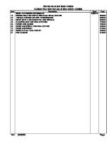
Fig. 1200 - CHASSIS COMPONENT
1/2
Item
Parts Number
Description
Qty
Remarks
-
PA0426-A1000000
TOWER LIGHT LS4-2000
1
-
1
SKF-2-1
TANK CHASSIS
1
2
SKF-2-2
INNER LEG
4
3
SKF-2-3
JACK
4
4
SKF-2-4
PIN 1
4
5
SKF-2-5
S PIN 1
4
6
SKF-2-6
VENT
1
7
SKF-2-7
FUEL LEVEL SENSOR
1
8
SKF-2-8
ABSORBER
4
9
SKF-2-9
ENGINE BRACKET RIGHT
1
10
SKF-2-10
RADIATOR MOUNTING
2
11
SKF-2-11
ENGINE BRACKET LEFT
1
12
SKF-2-12
ENGINE CROSS MEMBER
1
13
SKF-2-13
BATTERY
1
14
SKF-2-14
HYDRAULIC STATION SUPPORT
1
15
SKF-2-15
TANK LOCK
1
16
SKF-2-16
SMALL CHASSIS
1
17
SKF-2-17
HYDRAULIC STATION
1
2/2
Fig. 1200 - CHASSIS COMPONENT
57
58
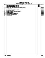
Fig. 1300 - GENERATOR SET
1/2
Item
Parts Number
-
Description
Qty
Remarks
GENERATOR SET
1
-
1
SKF-3-1
RADIATOR
1
2
SKF-3-2
SUPPORT 1
1
3
SKF-3-3
AUXILIARY RADIATOR
1
4
SKF-3-4
TANK HOSE 1
1
5
SKF-3-5
WATER TANK HOSE HOOPS
4
6
SKF-3-6
TANK HOSE 1
1
7
SKF-3-7
MUFFLER ASSEMBLY
1
8
SKF-3-8
ENGINE
1
9
SKF-3-9
EMPTY FILTER HOSE
1
10
SKF-3-10
HOOP
2
11
SKF-3-11
AIR FILTER
1
12
SKF-3-12
SUPPORT 2
1
13
SKF-3-13
ALTERNATOR
1
14
SKF-3-14
SWITCH
1
15
SKF-3-15
OIL FILTER 1
1
16
SKF-3-16
FUEL PUMP
1
17
SKF-3-17
SUPPORT 3
1
18
SKF-3-18
OIL FILTER 2
1
2/2
Fig. 1300 - GENERATOR SET
59
60
Fig. 1400 - ELECTRICAL BOX
1/2
Item
Parts Number
-
Description
Qty
Remarks
ELECTRICAL BOX
1
-
1
SKF-4-01
CONTROL BOX BODY
1
2
SKF-4-02
WATERPROFF ADHESIVE HEAD
6
3
SKF-4-03
RELAY 1
5
4
SKF-4-04
GUIDE LONG
1
5
SKF-4-05
SWITCH 1
1
6
SKF-4-06
CONNECTION TERMINAL
30
7
SKF-4-07
GUIDE SHORT
1
8
SKF-4-08
SWITCH 2
6
9
SKF-4-09
SAFETY BOX
1
10
SKF-4-10
GROUND BAR
1
11
SKF-4-11
TRUNKING 1
1
12
SKF-4-12
TRUNKING 2
1
13
SKF-4-13
TRUNKING 3
1
14
SKF-4-14
NEUTRAL BAR
1
15
SKF-4-15
CONTROL PANEL
1
16
SKF-4-16
HINGE
2
17
SKF-4-17
BUTTON
3
18
SKF-4-18
CONTROLLER
1
2/2
Fig. 1400 - ELECTRICAL BOX
61
62
Fig. 1500 - OUTER COVER COMPONENT
1/2
Item
Parts Number
-
Description
Qty
Remarks
OUTER COVER COMPONENT
1
-
1
SKF-5-01
LOUVER 1
1
2
SKF-5-02
WIND OUTLET PLATE
1
3
SKF-5-03
HEAD COVER
1
4
SKF-5-04
AIR INLET END PLATE
1
5
SKF-5-05
LOUVER 2
1
6
SKF-5-06
LIGHT POLE GUARD BEAM
1
7
SKF-5-07
REAR END PLATE 1
1
8
SKF-5-08
HINGE
8
9
SKF-5-09
REAR END PLATE 2
1
10
SKF-5-10
DOOR WITH LOCK 1
1
11
SKF-5-11
DOOR LOCK
2
12
SKF-5-12
DOOR LOCK ACCESSORIES 1
4
13
SKF-5-13
DOOR LOCK ACCESSORIES 2
4
14
SKF-5-14
DOOR LOCK ACCESSORIES 3
2
15
SKF-5-15
DOOR LOCK ACCESSORIES 4
2
16
SKF-5-16
DOOR LOCK ACCESSORIES 5
4
17
SKF-5-17
DOOR 1
1
18
SKF-5-18
BOTTOM CROSSBEAM
2
19
SKF-5-19
REAR END PLATE 3
1
20
SKF-5-20
LIFTING LUG 1
2
21
SKF-5-21
LIFTING LUG 2
2
22
SKF-5-22
WATER TANK RUBBER COVER
1
23
SKF-5-23
REAR END PLATE 4
1
24
SKF-5-24
THE OUTPUT SOCKET
1
25
SKF-5-25
EMERGENCY STOP SWITCH
1
26
SKF-5-26
MOUNTING BRACKET OF STEP-UP TRANSFORMER
1
27
SKF-5-27
STEP-UP TRANSFORMER
1
28
SKF-5-28
DOOR WITH LOCK 2
1
29
SKF-5-29
DOOR 2
1
30
SKF-5-30
CONTROL BOX MOUNTING BRACKET 1
1
31
SKF-5-31
CONTROL BOX MOUNTING BRACKET 2
1
32
SKF-5-32
CONTROL BOX MOUNTING BRACKET 3
1
33
SKF-5-33
SMOKE PIPE PROTECTIVE COVER
1
2/2
Fig. 1500 - OUTER COVER COMPONENT
63
64
Fig. 1601 - MAST 1 COMPONENT
1/2
Item
Parts Number
-
Description
Qty
Remarks
MAST 1 COMPONENT
1
-
1
SKF-6.1-01
MAST 1
1
2
SKF-6.1-02
NYLON PLATE 1
1
3
SKF-6.1-03
BOLT
14
4
SKF-6.1-04
CABLE
2
5
SKF-6.1-05
STAINLESS STEEL TUBE
2
6
SKF-6.1-06
THE LIFTING CYLINDER
1
7
SKF-6.1-07
NUT
2
8
SKF-6.1-08
PIN 1
2
9
SKF-6.1-09
BOLT
2
10
SKF-6.1-10
HOOP
1
11
SKF-6.1-11
PIN 2
1
12
SKF-6.1-12
PIN 3
1
13
SKF-6.1-13
NUT
1
2/2
Fig. 1601 - MAST 1 COMPONENT
65
66
Fig. 1602 - MAST 2 COMPONENT
1/2
Item
Parts Number
-
Description
Qty
Remarks
MAST 2 COMPONENT
1
-
1
SKF-6.2-1
MAST 2
1
2
SKF-6.2-2
PIN 1
1
3
SKF-6.2-3
NYLON PLATE 2
1
4
SKF-6.2-4
SCREW
10
5
SKF-6.2-5
SHEAVE
2
6
SKF-6.2-6
PIN 2
2
7
SKF-6.2-7
PIN 3
4
8
SKF-6.2-8
WIREROPE
2
9
SKF-6.2-9
PIN 3
1
2/2
Fig. 1602 - MAST 2 COMPONENT
67
68
Fig. 1603 - MAST 3 COMPONENT
1/2
Item
Parts Number
-
Description
Qty
Remarks
MAST 3 COMPONENT
1
-
1
SKF-6.3-1
MAST 3
1
2
SKF-6.3-2
PIN 1
1
3
SKF-6.3-3
PIN 2
2
4
SKF-6.3-4
SHEAVE
1
5
SKF-6.3-5
NYLON PLATE 3
1
6
SKF-6.3-6
SCREW
8
7
SKF-6.3-7
WIREROPE
2
8
SKF-6.3-8
PIN CLAMP
3
2/2
Fig. 1603 - MAST 3 COMPONENT
69
70
Fig. 1604 - MAST 4 COMPONENT
1/2
Item
Parts Number
-
Description
Qty
Remarks
MAST 4 COMPONENT
1
-
1
SKF-6.4-1
MAST 4
1
2
SKF-6.4-2
NYLON PLATE 4-2
1
3
SKF-6.4-3
NYLON PLATE 4-3
1
4
SKF-6.4-4
SCREW
8
5
SKF-6.4-5
PIN 1
1
6
SKF-6.4-6
PIN 2
2
7
SKF-6.4-7
SHEAVE
1
8
SKF-6.4-8
PIN CLAMP
4
9
SKF-6.4-9
WIREROPE
2
10
SKF-6.4-10
PIN 3 (WIREROPE)
1
2/2
Fig. 1604 - MAST 4 COMPONENT
71
72
Fig. 1605 - MAST 5 COMPONENT
1/2
Item
Parts Number
-
Description
Qty
Remarks
MAST 5 COMPONENT
1
-
1
SKF-6.5-1
MAST 5
1
2
SKF-6.5-2
NYLON PLATE 5-2
1
3
SKF-6.5-3
SCREW
6
4
SKF-6.5-4
NYLON PLATE 5-4
1
5
SKF-6.5-5
PIN 1 (WIREROPE)
2
6
SKF-6.5-6
SHEAVE
1
7
SKF-6.5-7
PIN 2
2
8
SKF-6.5-8
PIN CLAMP
4
9
SKF-6.5-9
PIN 3
1
10
SKF-6.5-10
WIREROPE
2
2/2
Fig. 1605 - MAST 5 COMPONENT
73
74
Fig. 1606 - MAST 6 COMPONENT
1/2
Item
Parts Number
-
Description
Qty
Remarks
MAST 6 COMPONENT
1
-
1
SKF-6.6-1
MAST 6
1
2
SKF-6.6-2
NYLON PLATE 6-2
1
3
SKF-6.6-3
NYLON PLATE 6-3
1
4
SKF-6.6-4
SCREW
6
5
SKF-6.6-5
PIN 1
2
6
SKF-6.6-6
PIN 2
1
7
SKF-6.6-7
PIN CLAMP
1
8
SKF-6.6-8
SHEAVE
1
9
SKF-6.6-9
WIREROPE
2
2/2
Fig. 1606 - MAST 6 COMPONENT
75
76
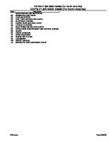
Fig. 1607 - MAST 7 COMPONENT
1/2
Item
Parts Number
-
Description
Qty
Remarks
MAST 7 COMPONENT
1
-
1
SKF-6.7-1
MAST 7
1
2
SKF-6.7-2
BOLT
4
3
SKF-6.7-3
ELECTRIC MOTOR
1
4
SKF-6.7-4
LIMIT JUNCTION BOX
1
SKF-6.7-4-1
SUPPORTING PLATE 1
1
SKF-6.7-4-2
BOX BODY 1
1
SKF-6.7-4-3
WATERPROOF ADHESIVE HEAD-1
5
SKF-6.7-4-4
GUIDE
1
SKF-6.7-4-5
RECTIFIER BRIDGE
1
SKF-6.7-4-6
TERMINAL TAIL TOP
2
SKF-6.7-4-7
CONNECTION TERMINAL
16
SKF-6.7-4-8
TIME RELAY
2
SKF-6.7-4-9
RELAY
4
SKF-6.7-4-10
COVER PLATE 1
1
5
SKF-6.7-5
LAMP HOLDER
2
6
SKF-6.7-6
BRACKET 1
1
7
SKF-6.7-7
MAGNET
1
8
SKF-6.7-8
BRACKET 2
1
9
SKF-6.7-9
INDUCTION PROBE
2
10
SKF-6.7-10
JUNCTION BOX
1
SKF-6.7-10-1
BRACKET 2
1
SKF-6.7-10-2
COVER PLATE 2
1
SKF-6.7-10-3
BOX BODY 2
1
SKF-6.7-10-4
WATERPROOF ADHESIVE HEAD-2
4
SKF-6.7-10-5
THE OUTPUT SOCKET
4
2/2
Fig. 1607 - MAST 7 COMPONENT
77