![Phthalic Anhydride: Design Project [PDF]](https://pdfs.asia/img/200x200/phthalic-anhydride-design-project.jpg)
13 0 2 MB
Phthalic Anhydride Design Project
Anisha Sharma - 216 Prarthna Shetty – 217
Contents 1
INTRODUCTION ........................................................................................................................................ 3 1.1
OVERVIEW ........................................................................................................................................ 3
1.2
MARKET CONDITIONS ...................................................................................................................... 4
2
1.2.1
GLOBAL MARKET ...................................................................................................................... 4
1.2.2
INDIAN MARKET ....................................................................................................................... 4
CAPACITY.................................................................................................................................................. 6 2.1
2.1.1
AUTOMOBILE INDUSTRY .......................................................................................................... 6
2.1.2
PVC ........................................................................................................................................... 6
2.1.3
PAINT INDUSTRY ...................................................................................................................... 6
2.2 3
END USER MARKET .......................................................................................................................... 6
PROPOSED CAPACITY ....................................................................................................................... 6
TECHNOLOGY SELECTION ........................................................................................................................ 7 3.1
AVAILABLE TECHNOLOGIES.............................................................................................................. 7
3.2
TECHNOLOGY SELECTED .................................................................................................................. 9
VAPOUR PHASE FIXED BED CATALYTIC OXIDATION OF O-XYLENE .......................................................... 9 4
PROCESS DESCRIPTION .......................................................................................................................... 11
5
PREPARATION OF PROCESS FLOW DIAGRAM ........................................................................................ 13 5.1
BLOCK DIAGRAM ............................................................................................................................ 13
5.2
PFD ................................................................................................................................................. 14
6
MASS BALANCE ...................................................................................................................................... 15
8
ENERGY BALANCE .................................................................................................................................. 18
9
LINE SIZING............................................................................................................................................. 21
10
PNID ................................................................................................................................................... 24
....................................................................................................................................................................... 24 10.1
PNID EQUIPMENT LIST ................................................................................................................... 27
11
MSDS .................................................................................................................................................. 28
12
EQUIPMENT DESIGN .......................................................................................................................... 29
12.1
REACTOR DESIGN (PROCESS) ......................................................................................................... 29
12.1.1 12.2
ENGINEERING SPECIFICATION SHEET FOR THE REACTOR (R101) .......................................... 32
DISTILLATION COLUMN DESIGN .................................................................................................... 33
12.2.1
DIAMETER OF COLUMN ......................................................................................................... 35
12.2.2
PLATE LAYOUT........................................................................................................................ 36
12.2.3
PLATE PRESSURE DROP .......................................................................................................... 36 1
12.2.4
OVERALL COLUMN EFFICIENCY .............................................................................................. 37
12.2.5
HEIGHT OF THE COLUMN....................................................................................................... 37
12.2.6
NOZZLES ................................................................................................................................. 37
12.2.7
AREA OF CONDENSER ............................................................................................................ 37
12.2.8
AREA OF REBOILER ................................................................................................................. 38
12.2.9
ENGINEERING SPECIFICATION SHEET FOR DISTILLATION COLUMN (T-101).......................... 41
13.
OSBL SPECIFICATIONS ........................................................................................................................ 42
13
PLANT LAYOUT ................................................................................................................................... 46
14
SAFETY, HEALTH AND ENVIRONMENT ............................................................................................... 50
14.1
SAFETY, HEALTH AND ENVIRONMENT COMPLIANCE STUDIES...................................................... 51
15
FINANCIAL ANALYSIS .......................................................................................................................... 54
16
CONCLUSION & RECOMMENDATIONS .............................................................................................. 57
17
REFERENCES ....................................................................................................................................... 58
2
1
INTRODUCTION
1.1 OVERVIEW Phthalic Anhydride (PA) is a principal commercial form of phthalic acid, discovered in 1836. It is an important chemical intermediate and its biggest application, accounting for just over half of production, is in the manufacture of phthalate plasticizers, the main product being dioctyl phthalate (DOP) which is used as a plasticizer in polyvinyl chloride (PVC). Hence, the consumption of PA is mainly dependent on the growth of flexible PVC, which is sensitive to general economic conditions as it is consumed in the construction and automobile industries.
Applications of PA
Plasticizers
10%
Unsaturated polyesters
15% 18%
57%
Alkyd resins
Others
The phthalate plasticizers application dominated the global market and accounted for 56.5% of the overall demand in 2012. Growing demand from the phthalate plasticizers market and strong demand from Asia Pacific were the major growth drivers for PA. Another important market for PA is unsaturated polyester resins, which accounted for 18.1% share of the total PA volume consumed in 2012. The growing demand of phthalate plasticizers in the production of polyvinyl chloride (PVC) and unsaturated polyester resins in the manufacturing of fiberglass-reinforced plastic (FRP) are expected to drive the global PA market in the next six years.
3
1.2 MARKET CONDITIONS 1.2.1
GLOBAL MARKET
The Phthalic Anhydride market was valued at USD 6.46 billion in 2012 and is expected to reach USD 9.58 billion by 2019, growing at a CAGR of 5.8% from 2013 to 2019. In terms of volumes, global consumption was over 4.3 million tons in 2012 and is expected to grow at a CAGR of 3.6% from 2013 to 2019.
Worldwide consumption of PA
27% Asia Pacific Europe 55%
ROW
18%
1.2.2
The global PA market is dominated by Asia Pacific, which accounted for 55.2% of global volumes consumed in 2012. Growth of PA in Asia Pacific is principally driven by the extensive use of PVC applications from growing end user industries such as automobile and construction in the region. It is the largest PA market, in terms of both production and consumption. Asia Pacific was followed by Europe with 17.8% share in total volume consumption.
INDIAN MARKET
With an aggregate installed capacity of 3,46,310 TPA across India, major PA producers include:
MANUFACTURER
CAPACITY (TPA)
IG Petrochemicals Ltd Thirumalai Chemicals Ltd Asian Paints Ltd S.I. Group
1,16,110 + 50,000 expanded 1,45,000 25,200 10,000
Apparent consumption of PA in INDIA was 2,68,806tons in 2012-2013. Capacity Utilization of the domestic industry is deemed to be around 75%. Mysore Petrochemicals Ltd with a capacity of 12,000-tpa shut down it’s plant as the operation had been incurring cash losses.
4
1.2.2.1 IMPORTS
Phthalic Anhydride is imported into India from a number of countries, and primarily from Republic of Korea, Israel, Iran, Taiwan, China and Russia. The imports of Phthalic Anhydride have shown an increasing trend in absolute terms as well as compared to the domestic production.
Imports have increased to 43420 MT in 2012-13 from 38894 MT in 2011-12. Further domestic production has increased to 225262 MT in 2012-13 from 215124 MT in 2011-12. Domestic production has therefore, increased by 5%. 1.2.2.2 EXPORTS
The domestic sales have increased to 196115 MT in 2012-13 from 177730 MT in the preceding year. The exports have slightly decreased to 26324 MT in 2012-13 from 40254 MT in the preceding year. The major export destinations are: Egypt, Saudi Arabia, UAE, Kuwait, Iran, China and Thailand.
5
2
CAPACITY
2.1 END USER MARKET 2.1.1
AUTOMOBILE INDUSTRY
The Indian automobile industry produced a total 1.69 million vehicles including passenger vehicles, commercial vehicles, three wheelers and two wheelers in August 2013 as against 1.56 million in August 2012, registering a growth of 8.18 percent over the same month last year. The overall automobile exports grew by 2.03 per cent during April-August 2013. Furthermore, the production of passenger vehicles in India was recorded at 3.23 million in 2012-13 and is expected to grow at a compound annual growth rate (CAGR) of 13 per cent during 2012-2021. 2.1.2
PVC
According to industry sources in India, the country’s PVC demand is currently pegged at 2.08 million mt/year. The consumption of PVC in India is expected to increase to 3.1 million mt/year by 2016-17. 2.1.3
PAINT INDUSTRY
The Indian paint industry is valued at Rs 26,000 crore with 71 per cent of it being decorative paints and the remaining being industrial. In volume terms, the size of the industry is 3.1 million tonnes with decorative paints being 2.4 million tonnes and industrial paints being 0.7 million tonnes. The paint market is estimated to double to Rs 50,000 crore by 2016 with per capita consumption increasing to over 4 kgs from 2.57 kgs. It is anticipated that this sector will post a CAGR of around 15% during FY 2012 to FY 2015.
2.2 PROPOSED CAPACITY PARAMETER Production in India in FY 12-13 Consumption in India in FY 12-13 Gap ---Gap in PA demand for PVC industry ---Gap in PA demand for Paint industry ---Gap in PA demand for other apps Forecasted rise in PVC demand by 2016 Forecasted rise in Paint demand by 2016 Capacity Utilization Capacity calculation CALCULATED CAPACITY PROPOSED CAPACITY
VALUE (MT) 2,25,262 2,68,808 43,546 0.29*43546 = 12629 0.28*43546 = 12193 18724 49% 15% (CAGR) 75% (43546/0.75)+(0.49*12629)+((1.15^3)*12193) 82800 Assuming 330 working days in a year 10 mT/hr production Capacity = 330*10*24 = 79200 mT/year
6
3
TECHNOLOGY SELECTION
3.1 AVAILABLE TECHNOLOGIES The available process technology for PA manufacture can be categorized via either Naphthalene or O-xylene as feed under: Vapour phase (fixed and fluid bed) and liquid phase. Fluidized bed processes mainly use naphthalene and their yield is lower than that of fixed bed processes, especially if they employ o-xylene.
NAPHTHALENE ROUTE Naphthalene route was adopted by the older Phthalic anhydride plants using process like Sherwin-williams/badger fluidized bed process. Fluidized-bed vs Fixed-bed. Phthalic anhydride has been manufactured by the oxidation of naphthalene in fixed-bed reactors for more than forty years. However, it is widely known that such reactors have inherent defects which make impossible the desired control of reaction conditions. The advent of the fluidized-bed reactor has made possible not only a much closer approach to these ideal reaction conditions but also several other important advantages which favourably influence the economics of the process. Advantages of fluidized bed over fixed bed 1. Greater Safety- prevents explosions and so permits operation well inside the explosive range of air:naphthalene ratios. 2. More precise control of reaction conditions-The high thermal conductivity and good heat-exchange characteristics of this fluidized-catalyst bed permits an exact control of reaction temperature without the formation of hot spots. Temperatures varying only by one or two deg F can be held throughout a fluidized bed containing up to 30 tons of catalyst or more. Pressure, temperature, air:naphthalene ratios and contact time can each be varied, independently and quickly, so permitting a rapid and exact adjustment of operating conditions to meetparticular requirements. 3. More efficient condensation of phthalic anhydride- A substantially lower air:naphthalene ratio makes possible the more efficient condensation of the reaction product because of its greater partial pressure in the product gases. Operating the reactor at increased pressure permits the condensation of 50% or moreof the product directly as liquid, the balance being condensed as solid in switch condensers. The lower concentration of oxygen in the product gases, compared with that obtained in fixed-bed plants, reduces the hazard of fire and explosion down stream from the reactor.
7
4. Liquid naphthalene feed- mixture of air and naphthalene vapour involving the use of a separate evaporator. This can give trouble. With a fluidized-catalyst reactor liquid naphthalene is pumped-directly into the reactor. 5. Catalyst charging- The tedious operation of charging catalyst pellets into the tubes of the fixed bed reactor is avoided. On the fluidized bed plant catalyst can be moved pneumatically from the reactor to the catalyst storage vessel or in the opposite direction, even whilst the plant is operating. 6. Operation at increased pressure- The operation of fluidized-catalyst reactors at increased pressure (1 to 2 atm. gauge) permits a substantial increase in the output of a particular unit compared with its capacity at atmospheric pressure. 7. High purity product- The precise control of reaction conditions in a fluidized catalyst reactor results in the formation of a crude product of high purity. The redistillation process is thereby considerably simplified, and a final sales product of a high standard of purity is obtained.
O-XYLENE ROUTE O-xylene is used as the raw material in Phthalic anhydride plants all over the world now. The consideration for process selection was on the basis of the following criteria: Process Criteria
Oxidation of O-xylene using a fixed bed vapor-phase
Oxidation of Naphthalene using fluidized bed vapor phase
Raw material Cost
Lower
Higher (it is in an impure form)
Raw material availability
More available
Less available (coal tar naphthalene)
8
Safety:
Less 1. CO2 emission 2. Processing Higher (350 to 500) Temperature
PA Yield
More Lower (340 to 385)
Higher (Complete combustion) Lower
3.2 TECHNOLOGY SELECTED VAPOUR PHASE FIXED BED CATALYTIC OXIDATION OF O-XYLENE Basis for selection: 1. Raw Materials : O-Xylene is readily available in large quantities for the manufacture of Phthalic Anhydride. Reliance Industries Limited is India’s largest manufacturer of Orthoxylene with a capacity of 150 KTA, and figures amongst the top 5 Orthoxylene producers in the world. Orthoxylene is produced at Reliance Jamnagar Complex as a co-product from the Paraxylene Plant. Contemporary processes are based on O-Xylene and all plants in India employ this route, as naphthalene is expensive and not easily available.The major outlet for naphthalene is now in the production of naphthalene sulfonates as a result of whose expanding NSF markets and feedslate shifts, it’s use in the consumption for phthalicanhydride has been reduced. Thus, O-xylene is the preferred raw material since it is higher yielding as all carbon atoms appear in the product), because of availability (naphthalene sources are becoming rarer) and cost (naphthalene is only available at a competitive cost in an impure form which is less suitable). 2. Utilities : Basic utilities required would be water, power, air and process water. Applied utilities include dowtherm as a heat transfer fluid, hot oil and cooling water. 3. Safety Health and Environment Compliance : Potential emissions to the environment from the proposed phthalic anhydride plant have been assessed in two categories: 9
(a) airborne emissions; (b) waterborne emissions; Airborne emissions will contain low concentrations of PAN and other organics but these will be satisfactorily dispersed by a stack. Waterborne emissions will be minimal but available treatment facilities will be utilised where required. The main process hazard which may occur during normal operation of phthalic anhydride plants is the risk of PAN dust clouds forming from minor process breaches. PAN dust clouds are both toxic (at concentrations below 1%) and explosive (at concentrations of 1.5-10.5%). Air quality monitoring will be utilised to identify process breaches producing dust clouds before they become hazardous. Appropriate breathing equipment (dust masks, respirators, etc.) will always be available. Also, the Toxicological Profile for Naphthalene and strict environmental regulations are limiting the use of Naphthalenes. 4. Simplicity of Process : In recent years, the fixed-bed vapour-phase process has proven to be superior to the alternatives and all plants built in the last ten years have used this process. Fluidized bed processes mainly use naphthalene and their yield is lower than that of fixed bed processes, especially if they employ o-xylene. Fluidised bed processes have proved difficult to maintain and have suffered from erosion problems and excessive catalyst losses. The construction costs of liquid-phase processes have proven prohibitive. 5. Valuable Intermediates and Co products: A Large amount of steam is generated which can be reused for energy purposes. Maleic anhydride produced can be sold. 6. Catalyst Recovery : Not much loss of catalyst as it is a fixed bed process 7. Backward and Forward Integration : Large quantity of Maleic Anhydride would need to be produced for forward integration.
10
4
PROCESS DESCRIPTION
Phthalic Anhydride (PA) today is produced from two main sources: 1. Production from o-xylene (Vapour phase: fixed, fluidized bed; Liquid phase) 2. Production from naphthalene(Fixed, Fluidized beds) Both main technologies involve specific catalyst for selective oxidation of raw material to product. The technology consists of 4 main phases:
Oxidation (performed in reactor block), Recuperation of Phthalic Anhydride from reactor off-gases (performed in switch condensing section) and Refining to commercial product (performed in distillation unit) Flaking and packing system
Any of Phthalic Anhydride production technologies include sub sections as:
Steam system – energy recuperation Waste gases incineration Recovery of Maleic anhydride from off gases of switch condensers
The raw o-xylene is pre-heated and mixed with a compressed air stream. Excess air is employed to ensure that the mixture is below the lower explosive limit of 1.5 mole percent o-xylene.Then, it enters a fixed-bed reactor where the crude product is obtained. Here, steam is generated which is used as a utility in the plant. In the reactor, four reactions occur:
1. 2. 3. 4.
C8H10 + 3O2 C8H10 + 7.5O2 C8H10 + 10.5O2 C8H10 + 6.5O2
C8H4O3 + 3H2O C4H2O3 + 4H2O + 4CO2 8CO2+ 5H2O 8CO+ 5H2O
The selectivity for the phthalic anhydride reaction is 70%, for the complete combustion of oxylene is 15%, for the incomplete combustion of o-xylene is 5%, for maleic anhydride is 9%, and for the heavy impurity is 1%. CATALYST: Many variations of the Vanadium oxide catalyst are possible. We have decided to employ a catalyst which consists of 3.75 wt% Vanadium oxide and 21.25 wt% potassium pyrosulphate on a titanium dioxide carrier (75 wt%). To activate the catalyst, about 65% of the vanadium is converted to the tetravalent state by heating in air containing SO2.
11
PREHEATER AND REACTOR SECTION: The o-xylene preheated to 140-150 deg C and air, filtered, compressed and preheated to 160 deg C, is introduced into the multi-tube reactor. The temperature is kept at 380 deg C by dowtherm circulation. A heat exchanger system installed on the coolant fluid circuit is used to produce high pressure steam. The catalyst is a mixture of vanadium and titanium oxides deposited on an inert, non-porous support. The gaseous reactor effluent is first cooled with the production of low-pressure steam and the residual gases scrubbed with water and then discharged to the atmosphere. CONDENSATION AND RECOVERY: The recovery of phthalic anhydride is done using a set of switch condensers. The condensed stream obtained is sent to switch condensers which are a complex set of condensers in which phthalic anhydride is first desublimated using cooled diathermic oil and then melted at 130 deg C and sent to a storage tank. The following fractions leave as the off gases: O-Xylene, Oxygen, Nitrogen, Water, Carbon Dioxide, Carbon Monoxide, Phthalic Anhydride, Maleic Anhydride and Heavy Impurity. DISTILLATION COLUMNS: The distillation columns consist of a stripping and a rectifying column. The stream enters the stripping column first. Here,the rest of the maleic anhydride comes out from the top as stream 5. 99% of the phthalic anhydride and all of the heavy impurity goes to Stream 6 as per purity requirements. Finally, stream enters the Rectifying column. Here, 99.9% of the phthalic anhydride, and any remaining maleic anhydride go to Stream 7, and all of the heavy impurity goes to Stream 8. INCINERATOR: The switch-condenser off-gas is treated by a scrubber-incinerator combination. Scrubbers are employed to recover Maleic anhydride before sending the rest of the gases to the incinerator for safe disposal. Another thermal incinerator treats all the waste streams from the product purification section (Distillation towers) of the plant. WASTE WATER STREAMS: Sources of waste water are steam boiler blowdown and scrubber. HEAT TRANSFER CIRCUITS: The process employs two heat-transfer systems: (1) a dowtherm system which removes heat from the reactor. This is important because the reactor reactions are highly exothermic and heat need to continuously be removed to minimize by-product formation and conserve the catalyst. (2) an organic fluid (diathermic oil) system that heats and cools the switch condenser.
12
5
PREPARATION OF PROCESS FLOW DIAGRAM
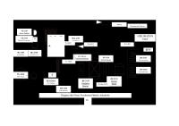
5.1 BLOCK DIAGRAM
13
5.2 PFD
14
6
MASS BALANCE
Feed Streams: 1. 2. 3. 4.
C8H10 + 3O2 C8H10 + 7.5O2 C8H10 + 10.5O2 C8H10 + 6.5O2
C8H4O3 + 3H2O C4H2O3 + 4H2O + 4CO2 8CO2+ 5H2O 8CO+ 5H2O
Assumptions:
Reaction 1 has a selectivity of 70%, Reaction 2 has 10% ,Reaction 3 has 15% and Reaction 4 has 5% Air : O-xylene ratio = 20:1 by weight PAN is being manufactured in excess of 2%
Input Rate + Generation rate – Output Rate – Consumption Rate = Accumulation
CO2 , CO
AIR
Maleic anhydride + Phthalic Anhydride + Water
O-XYLENE
A. Molecular Weights: Phthalic Anhydride – 148 Maleic Anhydride – 98 O-xylene – 106 B. Considering loss of 2 %, PA to be produced = 10,200 kg/hr C. Overall Mass Balance Element Calculation Phthalic Anhydride O-xylene
10200/148
Amount (kmol/hr) 68.92
68.92/0.7
98.46 15
required MA produced CO2 produced H2O produced CO produced Air O2 N2
98.46*0.1
9.846
(98.46*0.1*4)+(98.46*0.15*8)
157.534
(68.92*3)+(98.46*0.1*4)+(98.46*0.15*5)+(98.46*0.05*5) 344.614 98.46*0.05*8
39.38
98.46*106*20
(208735.2/29) = 7197.77 1511.53 5686.24
7197.77*0.21 7197.77*0.79
Oxygen Balance: Reaction 1: 98.46*0.7 *3= 206.77 kmol/hr Reaction 2 :98.46*0.1* 7.5= 73.845 kmol/hr Reaction 3: 98.46*0.15*10.5 = 155.07 kmol/hr Reaction 4: 98.46*0.05*6.5 = 32 kmol/hr Total O2 consumed = 206.77+73.845+155.07+32 = 467.685kmol/hr O2 unreacted = 1511.53- 467.685 = 1043.845kmol/hr Stream_in
Kmol/hr
Kg/hr
O-xylene O2 N2
98.46 1511.53 5686.24
10436.76 48368.96 159214.74
TOTAL
218,020.44
Stream_out
Kmol/hr
Kg/hr
CO MA PA O2 N2 CO2 H2O TOTAL
39.38 9.846 68.92 1043.845 5686.24 157.534 344.614
1102.64 964.908 10200.16 33403.04 159214.72 6931.496 6203.052 218020.016
16
INDIVIDUAL MASS BALANCE: Streams (kg/hr) O-xylene
1
2
3
4
5
6
7
8
-
-
-
-
-
-
-
-
-
-
-
-
-
-
-
-
-
-
-
-
-
6.203
6.203
-
-
-
MAN
-
33403. 04 159214 .72 6931.4 96 6196.8 5 1.93
-
H2O
9.6
9.5
0.1
-
10.2
10190
-
-
-
10169. 6 -