![POIRY STANDARD - Piping Standard [PDF]](https://pdfs.asia/img/200x200/poiry-standard-piping-standard.jpg)
7 0 3 MB
Orig.
14.11.14/J.Lindroos
14.11.14/S.Leinonen
14.11.14/J.Rautkorpi
14.11.14/J.Rautkorpi
Rev.
Date/Author
Date/Checked
Date/Approved
Date/Issued
Notes
SECN-L0018 2
Pöyry Finland Oy IBG Pulp & Paper P.O.Box 4 (Jaakonkatu 3) FI-01621 Vantaa Finland Domicile Vantaa, Finland Business ID. FI06259056 Tel. +358 10 3311 www.poyry.com Date November 14, 2014 Ref. No. 9HX191450-L0008
Project Standard
Page 2 (259) Contact Jarmo Lindroos Direct dial +358 10 33 22964 Direct fax +358 10 33 21818 E-mail [email protected]
PT. OKI PULP AND PAPER Indonesia
PIPING STANDARD Contents
1 2 3 4 5 6 7
General Austenitic Stainless Steel Piping Carbon Steel Piping Non-ferro-alloy Piping Plastic Piping Steam Traps, Seal Water and Service Piping Arrangements Primary Support Standards for Piping
PIPING STANDARD
9HX191450-L0008 3(259)
REVISED, ADDED OR DELETED STANDARDS: Date/ Standard No.
Added
Revised
Deleted
PIPING STANDARD
1
GENERAL
9HX191450-L0008 4(259)
PIPING STANDARD
9HX191450-L0008 5(259)
CONTENT
1(1) Related documents: 9HX191450-L0005, Technical Specification for Piping 9HX191450-L0007, Technical Specification for Piping Materials and Valve Selection General standards: 301-021
Maximum vacuum for austenitic stainless steel pipes
301-030
Weight of insulated gas pipes
301-040
Weight of uninsulated water pipes
301-045
Weight of insulated water pipes
301-050
Maximum support distances for stainless steel pipes
301-055
Maximum support distances for carbon steel pipes
301-057
Support distances for GRP pipes
301-070
Pipe bank spacing
301-090
Selection of Tee connection types
PIPING STANDARDS 9HX191450-L0008
GENERAL
6(259)
Pöyry Finland Oy IBG Pulp & Paper P.O.Box 4 (Jaakonkatu 3) FI-01621 Vantaa Finland Domicile Vantaa, Finland Business ID. FI06259056 Tel. +358 10 3311 www.poyry.com Date November 07, 2014
Project Standard
Ref. No 9HX191450-L0005 Page 1 (14) Contact Jarmo Lindroos Direct dial +358 10 33 22964 E-mail [email protected]
PT. OKI PULP AND PAPER Indonesia
TECHNICAL SPECIFICATION FOR PIPING Contents
1 General 2 Nominal Dimensions 3. Nominal Pressure Classes for Piping, Flanges and Valves 4 Materials, Dimensions and Certificates 5 Selection of Piping Materials and Valves 7 Erection 8 Marking of Pipelines 9 Documents 10 Inspections and Testing 11 Guarantees 12 Painting
PIPING STANDARDS 9HX191450-L0008
GENERAL
7(259)
Pöyry Finland Oy IBG Pulp & Paper P.O.Box 4 (Jaakonkatu 3) FI-01621 Vantaa Finland Domicile Vantaa, Finland Business ID. FI06259056 Tel. +358 10 3311 www.poyry.com Date November 07, 2014 Ref. No. 9HX191450-L0007
Project Standard
Page 1 (5) Contact Jarmo Lindroos Direct dial +358 10 33 22964 Direct fax +358 10 33 21818 E-mail [email protected]
PT. OKI PULP AND PAPER Indonesia
TECHNICAL SPECIFICATION FOR PIPING MATERIALS AND VALVE SELECTION Contents 1 2 3 4 5 6 Appendix
General Flow Substance Codes Piping Material Abbreviations Valve Material Abbreviations Flange Gaskets Valve Selection
I Flow Substances, Piping Material and Valve Recommendation
PIPING STANDARDS GENERAL MAXIMUM VACUUM FOR AUSTENITIC STAINLESS STEEL PIPES
9HX191450-L0008 8(259)
No.301-021
1(2) Table 1. Pipe material grades 1.4307 and 1.4432 at temperature 100 °C (extract of standard PSK 4299) 14.11.2014 Explanations for the table: jäykiste = stiffening ring, seinämänpaksuus = wall thickness p = maximum external pressure for pipe without stiffening rings. External pressure p is in 1bar (bar = 0,1 MPa). 1 bar means that the pipe stands full vacuum, L (mm) = maximum distance for stiffening rings for the full vacuum strength of pipe hs= stiffening ring height (mm), enw = stiffening ring thickness (mm)
PIPING STANDARDS GENERAL
MAXIMUM VACUUM FOR AUSTENITIC STAINLESS STEEL PIPES
9HX191450-L0008 9(259)
No.301-021 2(2) 14.11.2014
NOTE: The stiffening ring material is1.4307. * Nominal size will resist full vacuum = 1 bar (0,1 MPa) external pressure. ** The structure is not reasonable. The minimum wall thickness shall be according to the pipe classes in Section 2.
PIPING STANDARDS GENERAL
9HX191450-L0008 10(259)
PIPING STANDARD GENERAL
9HX191450-L0008 11(259)
WEIGHT OF INSULATED GAS PIPES
No: 301-030 1(5) 14.11.2014
Calculation data: - density of pipe material 7.9 kg/ dm3 - insulation density 160 kg/ m3 - cover plate density 7.9 kg/ dm3 - h = insulation thickness (mm) - s = wall thickness (mm) Dimensions D N
6
10
15
20
25
32
40
Do
10.2
17.2
21.3
26.9
33.7
42.4
48.3
h\s
Weight of insulated gas pipes kg/ m 1.6
1.8
2.0
2.3
2.6
2.9
3.2
3.6
4.0
4.5
5.0
5.6
40
2,93
2,96
3,00
60
4,73
4,77
4,80
80
6,94
6,97
7,00
40
3,47
3,54
3,61
3,70
3,79
3,88
60
5,34
5,41
5,48
5,57
5,67
5,75
80
7,62
7,69
7,75
7,85
7,94
8,03
40
3,79
3,88
3,96
4,09
4,21
4,33
4,44
4,59
4,72
4,88
60
5,70
5,79
5,88
6,00
6,13
6,24
6,36
6,50
6,64
6,80
80
8,02
8,11
8,19
8,32
8,44
8,56
8,67
8,82
8,95
9,11
40
4,22
4,34
4,45
4,62
4,78
4,94
5,10
5,30
5,49
5,72
5,93
6,17
60
6,19
6,31
6,42
6,59
6,75
6,91
7,07
7,27
7,46
7,69
7,90
8,15
80
8,56
8,68
8,79
8,96
9,13
9,29
9,44
9,64
9,83
10,06
10,28
10,52
40
4,74
4,89
5,04
5,26
5,48
5,69
5,89
6,16
6,42
6,73
7,03
7,37
60
6,78
6,93
7,08
7,30
7,52
7,73
7,93
8,20
8,46
8,77
9,07
9,41
90
10,60
10,75
10,89
11,11
11,33
11,54
11,74
12,01
12,27
12,58
12,88
13,23
40
5,42
5,61
5,80
6,08
6,36
6,64
6,91
7,26
7,61
8,03
8,44
8,91
70
8,76
8,95
9,14
9,42
9,70
9,98
10,25
10,60
10,95
11,37
11,78
12,25
90
11,49
11,68
11,87
12,15
12,43
12,71
12,98
13,33
13,68
14,10
14,51
14,98
50
6,91
7,14
7,36
7,68
8,01
8,33
8,64
9,05
9,46
9,95
10,43
10,99
70
9,30
9,52
9,74
10,07
10,39
10,71
11,03
11,44
11,84
12,34
12,82
13,38
13,63
13,86
14,08
14,41
14,73
15,05
15,36
15,77
16,18
16,67
17,15
17,71
100
PIPING STANDARDS GENERAL
9HX191450-L0008 12(259)
WEIGHT OF INSULATED GAS PIPES
No: 301-030 2(5) 14.11.2014
Dimensions DN
50
65
80
100
125
150
200
250
300
Do
60.3
76.1
88.9
114.3
139.7
168.3
219.1
273.0
323.9
h\ s
Weight of insulated gas pipes kg/ m 1.6
1.8
2.0
2.3
2.6
2.9
3.2
3.6
4.0
4.5
5.0
5.6
50
7,90
8,18
8,46
8,88
9,29
9,70
10,10
10,64
11,16
11,80
12,43
80
11,81
12,09
12,38
12,79
13,20
13,61
14,02
14,55
15,07
15,71
16,34
100
14,92
15,21
15,49
15,90
16,32
16,72
17,13
17,66
18,18
18,82
19,45
60
10,48
10,84
11,20
11,74
12,27
12,79
13,31
14,00
14,68
15,52
16,35
90
14,93
15,29
15,65
16,19
16,72
17,24
17,77
18,45
19,13
19,97
20,80
120
20,29
20,65
21,01
21,54
22,08
22,60
23,12
23,81
24,49
25,33
26,16
60
12,45
13,08
13,70
14,32
14,94
15,75
16,56
17,56
18,54
19,71
90
17,09
17,72
18,35
18,97
19,58
20,40
21,21
22,20
23,19
24,35
120
22,64
23,27
23,90
24,52
25,13
25,95
26,76
27,75
28,74
29,90
60
14,91
15,73
16,55
17,36
18,16
19,23
20,29
21,60
22,90
24,45
100
21,82
22,64
23,45
24,26
25,07
26,14
27,19
28,51
29,81
31,35
140
30,33
31,15
31,97
32,78
33,58
34,65
35,71
37,02
38,32
39,87
60
17,38
18,39
19,39
20,39
21,39
22,71
24,02
25,65
27,26
29,18
100
24,80
25,81
26,81
27,81
28,80
30,12
31,43
33,06
34,68
36,60
140
33,82
34,83
35,83
36,83
37,83
39,15
40,46
42,09
43,70
45,62
60
20,16
21,38
22,60
23,81
25,02
26,62
28,22
30,20
32,17
34,52
100
28,15
29,37
30,59
31,80
33,01
34,61
36,21
38,19
40,16
42,51
180
48,96
50,18
51,40
52,61
53,82
55,42
57,01
59,00
60,97
63,32
70
30,39
31,98
33,57
35,68
37,78
40,39
42,99
46,10
120
42,41
44,00
45,59
47,70
49,80
52,41
55,01
58,12
200
66,87
68,46
70,05
72,15
74,25
76,87
79,47
82,57
70
36,70
38,70
40,68
43,33
45,96
49,24
52,51
56,42
120
50,08
52,07
54,06
56,70
59,33
62,62
65,89
69,79
200
76,70
78,70
80,68
83,33
85,96
89,24
92,51
96,42
80
45,39
47,76
50,13
53,28
56,42
60,33
64,23
68,90
120
57,32
59,69
62,05
65,20
68,34
72,26
76,16
80,82
220
94,16
96,53
98,90
102,05
105,19
109,10
113,00
117,67
PIPING STANDARDS GENERAL
9HX191450-L0008 13(259)
WEIGHT OF INSULATED GAS PIPES
Dimensions DN
Do
h\ s
No: 301-030 3(5) 14.11.2014 Weight of insulated gas pipes kg/ m
5.6
5.9
6.3
7.1
8.0
8.8
10.0
11.0
12.5
50 50
60.3
80 100 60
65
76.1
90 120
80
100
125
150
200
250
300
88.9
114.3
139.7
168.3
219.1
273.0
323.9
60
19,71
90
24,35
120
29,90
60
24,45
26,23
28,23
100
31,35
33,13
35,13
140
39,87
41,64
43,65
60
29,18
31,40
33,91
100
36,60
38,82
41,33
140
45,62
47,84
50,35
60
34,52
37,24
40,31
43,73
100
42,51
45,23
48,30
51,72
180
63,32
66,03
69,11
72,53
70
46,10
47,64
49,70
53,78
58,34
62,35
68,32
73,24
80,52
120
58,12
59,66
61,71
65,80
70,36
74,37
80,34
85,25
92,54
200
82,57
84,12
86,17
90,26
94,81
98,83
104,80
109,71
116,99
70
56,42
60,96
66,11
71,87
76,96
84,53
90,78
100,07
120
69,79
74,33
79,48
85,25
90,33
97,90
104,16
113,45
200
96,42
100,96
106,11
111,87
116,96
124,53
130,78
140,07
80
68,90
74,32
80,48
87,38
93,48
102,57
110,08
121,27
120
80,82
86,24
92,41
99,31
105,40
114,49
122,01
133,19
220
117,67
123,09
129,25
136,15
142,25
151,34
158,85
170,04
PIPING STANDARDS GENERAL
9HX191450-L0008 14(259)
WEIGHT OF INSULATED GAS PIPES
Dimensions DN
350
400
500
600
700
800
900
Do
355.6
406.4
508.0
610.0
711.0
813.0
914.0
h\ s
1016.0
3.6
4.0
4.5
5.0
5.6
57,94
61,39
65,70
69,99
75,13
120
61,83
64,43
67,03
70,50
73,95
78,26
82,55
87,69
220
100,26
102,87
105,47
108,94
112,39
116,70
120,99
126,13
80
55,47
58,45
61,43
65,40
69,36
74,30
79,22
85,12
140
76,44
79,43
82,41
86,38
90,34
95,27
100,20
106,09
220
110,04
113,03
116,01
119,98
123,93
128,87
133,80
139,69
80
75,35
80,33
85,30
91,49
97,68
105,09
140
99,39
104,37
109,34
115,54
121,72
129,13
220
137,08
142,05
147,02
153,22
159,41
166,81
80
101,30
108,76
116,21
125,14
140
128,41
135,88
143,33
152,25
220
170,20
177,66
185,11
194,04
100
126,79
135,51
144,21
154,64
140
147,30
156,02
164,72
175,15
220
193,15
201,87
210,57
221,00
100
163,77
175,72
140
186,33
198,28
220
236,28
248,23
100
183,14
196,59
140
207,73
221,18
220
261,74
275,19
140
140
100 1220.0
3.2 54,47
220
120 0
2.9 51,87
100 1118.0
2.6 49,26
220
110 0
Weight of insulated gas pipes kg/ m
80
100 100 0
No: 301-030 4(5) 14.11.2014
140 220
PIPING STANDARDS GENERAL
9HX191450-L0008 15(259)
WEIGHT OF INSULATED GAS PIPES
Dimensions DN
350
Do
355.6
h\ s
500
600
700
800
900
100 0
110 0
120 0
406.4
508.0
610.0
711.0
813.0
914.0
1016.0
1118.0
1220.0
Weight of insulated gas pipes kg/ m 6.3
7.1
8.0
8.8
10.0
11.0
12.5
14.2
80
81,10
87,90
95,50
102,23
112,26
120,56
132,93
100
87,18
93,98
101,58
108,31
118,34
126,64
139,01
220
132,10
138,90
146,50
153,23
163,26
171,56
183,93
91,97
99,77
108,51
116,25
127,79
137,36
151,61
140
112,95
120,75
129,49
137,23
148,77
158,33
172,59
220
146,54
154,35
163,09
170,82
182,37
191,93
206,19
80
113,71
123,53
134,54
144,29
158,86
170,95
188,98
140
137,75
147,57
158,58
168,33
182,90
194,99
213,02
220
175,43
185,25
196,26
206,01
220,58
232,67
250,71
80
135,53
147,37
160,66
172,44
190,05
204,67
226,50
251,11
140
162,65
174,49
187,78
199,56
217,16
231,78
253,62
278,23
220
204,43
216,28
229,56
241,34
258,95
273,57
295,40
320,01
100
166,79
180,64
196,18
209,97
230,58
247,71
273,30
302,17
140
187,30
201,15
216,69
230,48
251,09
268,22
293,81
322,68
220
233,15
247,00
262,54
276,32
296,94
314,07
339,66
368,53
100
189,64
205,51
223,33
239,14
262,80
282,45
311,84
345,02
140
212,20
228,07
245,90
261,70
285,36
305,01
334,41
367,58
220
262,15
278,02
295,85
311,65
335,31
354,96
384,35
417,53
100
212,26
230,14
250,22
268,03
294,69
316,86
350,01
387,45
140
236,85
254,73
274,81
292,63
319,29
341,45
374,60
412,04
220
290,86
308,74
328,82
346,64
373,30
395,46
428,61
466,05
100
235,11
255,01
277,37
297,21
326,91
351,60
388,55
430,29
261,75
281,66
304,01
323,85
353,55
378,25
415,19
456,94
220
319,86
339,77
362,13
381,96
411,66
436,36
473,31
515,05
100
257,96
279,89
304,52
326,39
359,12
386,35
427,09
473,14
80 400
No: 301-030 5(5) 14.11.2014
140
140 286,65
308,58
333,22
355,08
387,82
415,04
455,79
501,83
220
348,86
370,79
395,43
417,29
450,03
477,26
518,00
564,05
100
280,80
304,76
331,67
355,56
391,34
421,09
465,64
515,98
311,55
335,50
362,42
386,31
422,08
451,84
496,38
546,73
377,86
401,82
428,73
452,62
488,40
518,15
562,70
613,04
140 220
PIPING STANDARDS GENERAL
9HX191450-L0008 16(259)
WEIGHT OF UNINSULATED WATER PIPES
No: 301-040 1(2) 14.11.2014
Calculation data: - pipe density 7.9 kg/ dm3 - water density 1.0 kg/ dm3 - s = wall thickness (mm) Note: For other densities (pipe and flow media) the weight shall be calculated case by case. Dimensions
Weight of uninsulated water pipes kg/ m
DN
Do
1.6
1.8
2.0
2.3
2.6
2.9
3.2
3.6
4.0
4.5
5.0
5.6
6
10.2
0,38
0,41
0,44
0,48
0,51
0,54
0,57
0,60
0,62
0,64
0,65
0,64
10
17.2
0,77
0,83
0,89
0,98
1,06
1,13
1,20
1,29
1,38
1,47
1,55
1,64
15
21.3
1,04
1,12
1,19
1,30
1,41
1,51
1,61
1,74
1,86
2,00
2,12
2,26
20
26.9
1,45
1,55
1,65
1,79
1,94
2,08
2,21
2,39
2,55
2,75
2,94
3,15
25
33.7
2,01
2,14
2,27
2,46
2,64
2,83
3,01
3,24
3,47
3,74
4,00
4,30
32
42.4
2,83
3,00
3,16
3,41
3,66
3,90
4,13
4,44
4,74
5,11
5,47
5,88
40
48.3
3,45
3,65
3,84
4,13
4,41
4,69
4,96
5,32
5,67
6,10
6,53
7,02
50
60.3
4,89
5,14
5,38
5,75
6,11
6,46
6,82
7,28
7,74
8,30
8,85
9,50
65
76.1
7,13
7,45
7,76
8,23
8,69
9,15
9,61
10,21
10,80
11,53
12,25
13,11
80
88.9
9,97
10,52
11,07
11,61
12,15
12,86
13,57
14,44
15,30
16,32
100
114.3
15,13
15,84
16,56
17,26
17,97
18,90
19,82
20,97
22,11
23,46
125
139.7
21,30
22,18
23,05
23,93
24,80
25,95
27,09
28,52
29,93
31,61
150
168.3
29,46
30,52
31,59
32,64
33,70
35,10
36,49
38,22
39,95
42,00
200
219.1
48,51
49,90
51,29
52,68
54,52
56,35
58,64
60,91
63,62
250
273.0
72,03
73,77
75,51
77,25
79,56
81,86
84,73
87,58
90,99
300
323.9
98,43
100,51
102,58
104,64
107,39
110,13
113,55
116,96
121,04
350
355.6
116,93
119,21
121,49
123,76
126,78
129,80
133,56
137,31
141,80
400
406.4
155,08
157,69
161,15
164,61
168,92
173,22
178,37
450
457
192,58
195,51
199,41
203,31
208,17
213,02
218,83
500
508
234,44
237,70
242,04
246,38
251,80
257,20
263,67
600
610
339,57
344,79
351,31
357,82
365,62
700
711
452,24
458,34
465,95
473,55
482,66
800
813
597,99
606,70
617,13
900
914
744,84
754,64
766,39
100 0
1016 909,40
920,31
933,38
110 0
1118 1090,3
1102,3
1116,7
120 0
1220 1287,6
1300,7
1316,4
PIPING STANDARDS GENERAL
9HX191450-L0008 17(259)
WEIGHT OF UNINSULATED WATER PIPES
Dimensions
No: 301-040 2(2) 14.11.2014
Weight of uninsulated water pipes kg/ m
DN
Do
6.3
7.1
8.0
10.0
11.0
12.5
14.2
16.0
17.5
20.0
22.2
25.0
6
10.2
10
17.2
15
21.3
20
26.9
25
33.7
32
42.4
40
48.3
50
60.3
65
76.1
80
88.9
100
114.3
25,01
26,76
125
139.7
33,55
35,74
150
168.3
44,37
47,06
50,04
200
219.1
66,76
70,33
74,31
83,03
87,32
93,68
250
273.0
94,96
99,46
104,49
115,55
121,01
129,12
300
323.9
125,77
131,15
137,18
150,44
157,01
166,77
350
355.6
147,02
152,95
159,59
174,23
181,48
192,28
400
406.4
184,36
191,17
198,81
215,64
224,00
236,45
500
508
225,58
233,27
241,89
260,93
270,38
284,47
450
457
271,20
279,77
289,39
310,63
321,19
336,94
600
610
374,69
385,04
396,64
422,31
435,08
454,15
475,64
498,26
517,01
700
711
493,27
505,37
518,95
548,99
563,95
586,30
611,52
638,08
660,11
696,61
728,51
768,79
800
813
629,29
643,16
658,72
693,19
710,36
736,03
765,00
795,55
820,89
862,92
899,68
946,16
900
914
780,08
795,70
813,23
852,08
871,44
900,39
933,09
967,57
996,20
1043,7
1085,3
1137,9
100 0
1016 948,62
966,01
985,53
1028,8
1050,4
1082,6
1119,1
1157,6
1189,5
1242,5
1289,0
1347,8
110 0
1118 1133,5
1152,7
1174,2
1221,9
1245,6
1281,2
1321,5
1363,9
1399,2
1457,7
1509,0
1574,0
120 0
1220 1334,7
1355,7
1379,2
1431,3
1457,3
1496,2
1540,1
1586,6
1625,2
1689,2
1745,4
1816,6
PIPING STANDARDS GENERAL
9HX191450-L0008 18(259)
WEIGHT OF INSULATED WATER PIPES
No: 301-045 1(5) 14.11.2014
Calculation data:
- pipe density - insulation density - cover plate density - water density
7.9 kg/ dm3 160 kg/ m3 7.9 kg/ dm3 1.0 kg/ dm3
Note: For other densities (pipe and flow media) the weight shall be calculated case by case. D N
6
10
Do
10.2
17.2
h\ s
21.3
26.9
33.7
42.4
48.3
2.9
3.6
4.0
2,31
2,35
2,38
2,43
2,46
40
2,97
3,00
3,03
3,06
3,10
3,13
3,19
3,21
100
9,58
9,61
9,64
9,68
9,71
9,74
9,80
9,82
30
2,84
2,90
2,96
3,04
3,12
3,20
3,36
3,44
40
3,62
3,68
3,74
3,83
3,91
3,98
4,14
4,23
10,45
10,51
10,57
10,65
10,73
10,81
10,97
11,05
30
3,24
3,32
3,39
3,50
3,61
3,71
3,94
4,05
40
4,04
4,12
4,20
4,31
4,41
4,52
4,74
4,86
10,99
11,07
11,15
11,26
11,36
11,47
11,69
11,81
30
3,83
3,93
4,03
4,17
4,32
4,46
4,77
4,93
50
5,60
5,70
5,80
5,94
6,09
6,23
6,54
6,70
11,78
11,88
11,98
12,13
12,27
12,41
12,72
12,89
30
4,61
4,74
4,87
5,06
5,25
5,43
5,84
6,07
50
6,44
6,58
6,70
6,90
7,08
7,27
7,68
7,91
12,80
12,93
13,06
13,25
13,44
13,62
14,03
14,26
30
5,71
5,88
6,05
6,29
6,54
6,78
7,32
7,62
50
7,64
7,80
7,97
8,22
8,46
8,70
9,25
9,55
100
40
2.6
2,28
100
32
2.3
2,25
100
25
2.0
2,22
100
20
1.8
30
100
15
1.6
14,21
14,38
14,54
14,79
15,04
15,28
15,82
16,12
40
7,47
7,66
7,86
8,14
8,42
8,70
9,34
9,69
50
8,51
8,71
8,90
9,18
9,47
9,75
10,38
10,73
15,23
15,43
15,62
15,91
16,19
16,47
17,10
17,45
9,36
9,60
9,85
10,21
10,57
10,93
11,75
12,20
100 40
PIPING STANDARDS GENERAL 50
65
60.3
76.1
9HX191450-L0008 19(259) 60
11,66
11,91
12,16
12,52
12,88
13,24
14,05
14,51
100
17,48
17,73
17,98
18,34
18,70
19,06
19,87
20,33
40
12,19
12,51
12,82
13,29
13,75
14,21
15,26
15,86
60
14,66
14,97
15,28
15,75
16,21
16,67
17,73
18,32
100
20,79
21,11
21,42
21,89
22,35
22,81
23,87
24,46
PIPING STANDARDS GENERAL
9HX191450-L0008 20(259)
WEIGHT OF INSULATED WATER PIPES
Dimensions DN
80
100
125
150
200
250
300
350
Do
88.9
114.3
139.7
168.3
219.1
273.0
323.9
355.4
h\s
No: 301-045 2(5) 14.11.2014
Weight of insulated water pipes kg/ m 2.0
2.3
2.6
2.9
3.2
3.6
4.0
4.5
5.0
50
16,76
17,31
17,86
18,40
18,94
19,65
20,35
21,22
22,09
60
18,11
18,66
19,20
19,75
20,28
21,00
21,70
22,57
23,43
100
24,50
25,05
25,60
26,14
26,68
27,39
28,10
28,97
29,83
50
22,99
23,71
24,42
25,13
25,83
26,76
27,69
28,84
29,97
70
26,04
26,76
27,47
28,18
28,88
29,81
30,74
31,89
33,02
100
31,37
32,09
32,80
33,51
34,21
35,14
36,07
37,22
38,35
50
30,24
31,12
32,00
32,87
33,74
34,89
36,04
37,46
38,87
70
33,55
34,43
35,30
36,18
37,05
38,20
39,34
40,77
42,18
100
39,26
40,14
41,02
41,89
42,76
43,91
45,06
46,48
47,89
50
39,62
40,68
41,74
42,80
43,86
45,26
46,65
48,38
50,11
70
43,21
44,28
45,34
46,40
47,45
48,85
50,25
51,98
53,70
100
49,35
50,42
51,48
52,54
53,60
55,00
56,39
58,12
59,84
50
59,43
60,83
62,22
63,61
65,00
66,84
68,67
70,96
73,23
80
65,74
67,14
68,53
69,92
71,30
73,15
74,98
77,26
79,53
100
70,45
71,84
73,24
74,63
76,01
77,85
79,69
81,97
84,24
50
84,89
86,64
88,38
90,12
91,86
94,17
96,47
99,34
102,19
80
92,01
93,76
95,50
97,24
98,98
101,29
103,59
106,46
109,31
100
97,26
99,01
100,75
102,49
104,23
106,54
108,84
111,70
114,56
60
115,65
117,73
119,81
121,88
123,94
126,69
129,44
132,86
136,26
80
121,01
123,09
125,17
127,24
129,30
132,05
134,80
138,21
141,62
100
126,77
128,85
130,93
133,00
135,06
137,81
140,56
143,97
147,38
60
135,32
137,61
139,89
142,16
144,43
147,46
150,47
154,23
157,98
80
141,00
143,28
145,56
147,84
150,11
153,13
156,15
159,91
163,66
100
147,08
149,36
151,64
153,91
156,19
159,21
162,22
165,98
169,73
PIPING STANDARDS GENERAL
9HX191450-L0008 21(259)
WEIGHT OF INSULATED WATER PIPES
Dimensions DN
80
100
125
150
200
250
300
350
Do
88.9
114.3
139.7
168.3
219.1
273.0
323.9
355.4
No: 301-045 3(5) 14.11.2014
Weight of insulated water pipes kg/ m h\ s
5.6
5.9
6.3
7.1
8.0
8.8
10.0
11.0
50
23,10
23,61
24,27
25,58
27,02
28,27
30,10
31,57
60
24,45
24,95
25,62
26,93
28,37
29,62
31,44
32,91
100
30,85
31,35
32,01
33,32
34,76
36,01
37,84
39,31
50
31,32
31,99
32,87
34,62
36,56
38,25
40,73
42,76
70
34,37
35,04
35,92
37,67
39,61
41,30
43,78
45,81
100
39,70
40,37
41,25
43,00
44,94
46,63
49,11
51,14
50
40,55
41,38
42,49
44,68
47,11
49,24
52,39
54,96
70
43,86
44,69
45,80
47,99
50,42
52,55
55,69
58,27
100
49,57
50,40
51,51
53,70
56,13
58,26
61,41
63,98
50
52,16
53,18
54,53
57,22
60,20
62,83
66,72
69,91
70
55,75
56,77
58,12
60,81
63,80
66,43
70,31
73,51
100
61,89
62,91
64,27
66,95
69,94
72,57
76,46
79,65
50
75,94
77,29
79,08
82,65
86,63
90,14
95,35
99,64
80
82,25
83,60
85,39
88,96
92,94
96,44
101,66
105,95
100
86,95
88,30
90,10
93,66
97,64
101,15
106,36
110,66
50
105,61
107,31
109,57
114,07
119,10
123,54
130,16
135,62
80
112,72
114,43
116,69
121,19
126,22
130,66
137,27
142,74
100
117,97
119,67
121,94
126,44
131,47
135,91
142,52
147,99
60
140,34
142,37
145,07
150,46
156,48
161,81
169,74
176,31
80
145,70
147,73
150,43
155,82
161,84
167,17
175,10
181,67
100
151,46
153,49
156,19
161,58
167,60
172,93
180,86
187,43
60
162,46
164,70
167,68
173,61
180,25
186,12
194,87
202,12
80
168,14
170,38
173,35
179,28
185,92
191,79
200,55
207,80
100
174,22
176,45
179,43
185,36
192,00
197,87
206,63
213,88
PIPING STANDARDS GENERAL
9HX191450-L0008 22(259)
WEIGHT OF INSULATED WATER PIPES
Dimensions DN
400
500
600
700
800
900
100 0
Do
406.4
508
610
711
813
914
1016
Weight of insulated water pipes kg/ m h\ s 60 80
3.6
4.0
4.5
5.0
5.6
184,37
187,83
192,14
196,45
201,59
181,89
184,49
187,10
190,56
194,02
198,33
202,63
207,78
100
188,48
191,08
193,69
197,15
200,61
204,92
209,22
214,37
70
262,77
266,04
269,31
273,65
277,99
283,40
288,81
295,28
80
266,43
269,70
272,96
277,31
281,65
287,06
292,46
298,93
100
274,04
277,31
280,57
284,92
289,26
294,67
300,07
306,54
70
363,45
367,38
371,31
376,54
381,76
388,28
394,79
402,58
80
367,62
371,55
375,47
380,70
385,93
392,45
398,96
406,75
100
376,25
380,18
384,11
389,34
394,56
401,08
407,59
415,39
70
479,24
483,83
488,41
494,52
500,61
508,23
515,83
524,94
80
483,91
488,50
493,08
499,19
505,29
512,90
520,51
529,62
100
493,56
498,15
502,74
508,84
514,94
522,56
530,16
539,27
70
612,44
617,69
622,93
629,92
636,91
645,63
654,34
664,77
80
617,62
622,87
628,12
635,11
642,10
650,82
659,52
669,96
100
628,30
633,55
638,80
645,79
652,77
661,49
670,20
680,64
70
760,43
766,34
772,24
780,11
787,97
797,78
807,59
819,34
80
766,13
772,03
777,94
785,80
793,66
803,48
813,28
825,03
100
777,82
783,73
789,63
797,50
805,36
815,17
824,97
836,72
70
926,15
932,73
939,29
948,04
956,79
967,71
978,62
991,69
932,36
938,93
945,50
954,25
963,00
973,91
984,82
997,90
945,08
951,65
958,22
966,97
975,71
986,63
997,54
1010,62
80
80
70 1220
3.2 180,91
100
120 0
2.9 178,31
70 1118
2.6 175,70
100
110 0
No: 301-045 4(5) 14.11.2014
80 100
PIPING STANDARDS GENERAL
9HX191450-L0008 23(259)
WEIGHT OF INSULATED WATER PIPES
Dimensions DN
400
500
600
700
800
900
100 0
Do
406.4
508
610
711
813
914
1016
Weight of insulated water pipes kg/ m h\ s
120 0
1220
6.3
7.1
8.0
8.8
10.0
11.0
204,16
207,58
214,40
222,03
228,79
238,87
247,22
80
210,35
213,77
220,58
228,22
234,97
245,06
253,41
100
216,94
220,36
227,17
234,81
241,56
251,65
260,00
70
298,51
302,80
311,38
321,00
329,52
342,24
352,80
80
302,16
306,46
315,04
324,65
333,17
345,90
356,45
100
309,77
314,07
322,65
332,26
340,78
353,51
364,06
70
406,48
411,66
422,00
433,61
443,90
459,28
472,04
80
410,64
415,83
426,17
437,78
448,07
463,44
476,21
100
419,28
424,46
434,81
446,42
456,70
472,08
484,85
70
529,49
535,55
547,65
561,22
573,26
591,27
606,22
80
534,17
540,22
552,32
565,90
577,94
595,94
610,90
100
543,82
549,88
561,97
575,55
587,59
605,59
620,55
70
669,98
676,93
690,79
706,36
720,17
740,83
758,00
80
675,17
682,12
695,98
711,55
725,36
746,02
763,18
100
685,85
692,79
706,66
722,23
736,03
756,69
773,86
70
825,20
833,02
848,64
866,18
881,74
905,02
924,38
80
830,90
838,72
854,34
871,87
887,43
910,72
930,08
100
842,59
850,41
866,03
883,57
899,13
922,41
941,77
70
998,22
1006,93
1024,31
1043,84
1061,17
1087,11
1108,68
1004,43
1013,14
1030,52
1050,05
1067,38
1093,32
1114,89
1017,15
1025,85
1043,24
1062,77
1080,10
1106,04
1127,60
1197,17
1216,33
1237,85
1256,94
1285,54
1309,32
1203,90
1223,05
1244,57
1263,66
1292,26
1316,04
100
1217,64
1236,79
1258,31
1277,41
1306,00
1329,78
70
1403,76
1424,69
1448,19
1469,06
1500,31
1526,30
1411,00
1431,92
1455,43
1476,29
1507,54
1533,53
1425,77
1446,69
1470,20
1491,06
1522,31
1548,30
80
70 1118
5.9
60
100
110 0
No: 301-045 5(5) 14.11.2014
80
80 100
PIPING STANDARD GENERAL
9HX191450-L0008 24(259)
MAXIMUM SUPPORT DISTANCES FOR STAILESS STEEL PIPES
1
No: 301-050 1(3) 14.11.2014
SUPPORT DISTANCE SELECTION Table 1
DN
Support distances l (m) for stainless steel pipes at design temperature T [°C]
OUTSIDE DIAMETER x
UNINSULATED PIPE
WALL THICKNESS
INSULATED PIPE
T < 50 °C
T < 120°C
GAS
WATER
GAS
WATER
15 20 25 32
21.3 x 1.6 26.9 x 1.6 33.7 x 1.6 42.4 x 1.6
2.2 2.5 2.8 3.2
2.0 2.3 2.5 2.8
1.7 2.0 2.0 2.2
1.6 1.8 1.8 2.1
40 50 65 80
48.3 x 1.6 60.3 x 1.6 76.1 x 1.6 88.9 x 2.0
3.4 4.8 5.3 5.8
2.9 4.0 4.3 4.7
2.4 3.6 3.7 4.2
2.2 3.3 3.4 3.9
100 125 150 200
114.3 x 2.0 139.7 x 2.0 168.3 x 2.0 219.0 x 2.0
6.6 7.3 8.0 9.1
5.1 5.5 5.8 6.3
4.9 5.5 5.9 6.8
4.4 4.8 5.1 5.7
250 350 400 450
273.0 x 2.0 323.9 x 2.6 406.4 x 3.2 457 x 3.2
10.2 11.6 12.5 13.2
6.7 7.7 8.0 8.5
7.8 9.1 9.8 10.3
6.2 7.2 7.5 8.0
500 600 700 800
508 x 4.0 610 x 4.0 711 x 4.0 813 x 4.0
13.9 15.3 16.5 17.8
8.9 9.4 10.3 10.8
11.3 12.5 14.0 15.8
8.5 9.9 9.9 10.5
900
914 x 4.0
18.8
11.2
11.1
10.7
1000 1200
1016 x 5.0 1220 x 6.3
19.9 19.4
11.5 11.9
17.0 17.3
11.0 11.5
PIPING STANDARDS GENERAL
9HX191450-L0008 25(259)
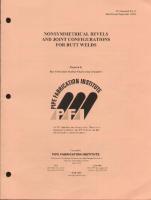
Figure 1
Freely supported pipe
MAXIMUM SUPPORT DISTANCES FOR STAILESS STEEL PIPES
No: 301-050 2(3) 14.11.2014
Table 1 gives support distances for freely supported pipe. These values can be multiplied by x = 1.5 for gas and x = 1.3 for water pipes on straight parts of the pipelines shown in Figure 2.
Figure. 2
Pipeline supporting
Heavy valves and other piping equipment shall be placed near the support. Also elbows should have a support near them to prevent sagging of the pipeline.
PIPING STANDARDS GENERAL
9HX191450-L0008 26(259)
MAXIMUM SUPPORT DISTANCES FOR STAILESS STEEL PIPES
2
No: 301-050 2(3) 14.11.2014
CALCULATION BASIS Support distances in Table 1 have been calculated for freely supported pipe (Figure 1) by formula:
I =
4
384 E I f 5q
where: l E I f q
= = = = =
support distance [mm] young’s modulus of elasticity [N/mm2] moment of inertia [mm4] deflection [mm] continuous unit load [N/mm2]
Maximum deflection is limited to following: fmax < 3 mm, for DN < 50 fmax < 7 mm, for DN > 50 fmax < 1/800 Young’s modulus of elasticity used in different temperatures are:
3
T [ °C ]
E [ N/mm2 ]
50 120 180
198 000 193 000 187 000
BENDING STRESS Bending stress for freely supported pipe have been checked applying formula: q 12 D 1 < x 0.2 v 16I 2 n
where:
PIPING STANDARDS GENERAL
9HX191450-L0008 27(259)
D 0.2 n v
= = = =
outside dismeter [mm] design stress [N/mm2] 1.5 0.7
PIPING STANDARDS GENERAL
9HX191450-L0008 28(259)
MAXIMUM SUPPORT DISTANCES FOR CARBON STEEL PIPES
No: 301-055 1(3) 14.11.2014
Table 1 Support distances 1 (m) for carbon steel pipes at design temperature T [°C] UNINSULATED PIPE, T 60C
INSULATED PIPE T 120C
PIPE DN
Do x T
GAS (m)
WATER (m)
GAS, (m)
STEAM
15
21.3 x 2.0
2.2
2.0
1.4
1.4
20
26.9 x 2.3
2.5
2.3
1.7
1.6
25
33.7 x 2.6
2.8
2.5
1.8
1.8
32
42.4 x 2.6
3.2
2.8
2.2
2.1
40
48.3 x 2.6
3.4
2.9
2.4
2.2
50
60.3 x 2.9
4.8
4.1
2.7
2.5
65
76.1 x 2.9
5.3
4.3
3.7
3.4
80
88.9 x 3.2
5.8
4.7
4.2
3.9
100
114.3 x 3.6
6.6
5.1
4.9
4.4
125
139.7 x 4.0
7.3
5.5
5.5
4.8
150
168.3 x 4.5
8.0
5.8
5.9
5.1
200
219.1 x 6.3
9.1
6.3
6.8
5.7
250
273.0 x 6.3
10.2
6.7
7.8
6.2
300
323.9 x 7.1
11.1
7.5
8.6
6.9
350
355.6 x 5.6
11.6
7.7
9.1
7.2
400
406.4 x 6.3
12.5
8.0
9.8
7.5
500
508.0 x 6.3
13.9
8.9
11.3
8.5
600
610.0 x 6.3
15.3
9.4
12.5
9.0
700
711.0 x 7.1
16.5
10.3
14.0
9.9
800
813 x 8.0
17.8
12.5
16.6
12.2
900
914 x 10.0
18.9
13.5
17.6
13.2
1000
1016 x 10.0
19.9
13.9
18.6
13.6
1200
1220 x 12.5
21.8
15.4
20.6
15.1
1) Support distances at design temperaturę higher than 120°C shall to be specified separately. 2) Support distances for DN sizes bigger than 1200 shall to be specified case by case.
WATER (m)
PIPING STANDARDS GENERAL
9HX191450-L0008 29(259)
MAXIMUM SUPPORT DISTANCES FOR CARBON STEEL PIPES
No: 301-055 2(3) 14.11.2014
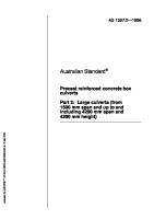
4 Support distance L has been calculated as freely supported pipe (Figure 1) by formula:
Figure Fig. 1 1
l =
4
384 E I f 5q
where: I = moment of inertia [mm4] E = young’s modulus of elasticity [N/mm2] q = continuous load [N/mm] f = deflection [mm] fmax = L/400 fmax = 3 mm, when DN 50 fmax = 7 mm, when DN 50
5 The support distance L can be multiplied by 1.5 if the pipe continues symmetrically at the both pipe ends or if the pipe is fixed in one end and continues symmetrically at the other end (See Figure 2).
PIPING STANDARDS GENERAL
9HX191450-L0008 30(259)
Figure 2
MAXIMUM SUPPORT DISTANCES FOR CARBON STEEL PIPES
No: 301-055 3(3) 14.11.2014
6 Axial stresses caused gravity load calculated with the support distances in the table from 10 N/mm2 to 50 N/mm2. With support distance 1.5 x l as specified in item 2 the stresses can be multiplied by 1.5.
PIPING STANDARDS GENERAL
9HX191450-L0008 31(259)
SUPPORT DISTANCES FOR GRP PIPES
1
No: 301-057 1(2) 14.11.2014
GENERAL Following table 1 gives support distances for water pipes with different design pressures (PN) and temperatures 60 C. For temperatures 60 C support distances shall be reduced by 1 % per 1 C. For gas pipes support distances in the table can be doubled but should not exceed 6 m.
2
REQUIREMENTS Pipes shall be according to standards 340-001.
3
Minimum axial module
E = 10 000 N/ m2
Minimum tangential module
E = 25 000 N/ m2
CALCULATION BASIS In calculation pipe is freely supported. Deflection (f) limits: f max< 3 mm, for DN 50 f max< 7 mm, for DN 50 f max< L / 700, where L =support distance The maximum allowable strain is 0.1 %.
PIPING STANDARDS GENERAL
9HX191450-L0008 32(259)
SUPPORT DISTANCES FOR GRP PIPES
No: 301-057 2(2) 14.11.2014
Table1 Support distances (m) for GRP pipes Maximum pressure Nominal pressure/ DN 15 20 25 32 40 50 65 80 100 125 150 200 250 300 350 400 500 600 700 800 900 1000 1100 1200
0 MPa
0,1 MPa
0,25 MPa
0,4 MPa
0,6 MPa
1 MPa
1,6 MPa
PN1
PN2.5
PN4
PN6
PN10
PN16
PN25
1.0 1.5 1.5 1.5 1.5 2.0 2.0 2.0 2.5 2.5 3.0 3.0 3.5 3.5 4.0 4.0 4.5 5.0 5.0 5.0 5.5 6.0 6.0 6.0
1.0 1.5 1.5 1.5 2.0 2.0 2.0 2.5 2.5 3.0 3.0 3.5 3.5 4.0 4.0 4.0 4.5 4.5 4.5 5.0 5.0 5.5 5.5 5.5
1.0 1.5 1.5 1.5 2.0 2.0 2.0 2.5 3.0 3.0 3.0 3.0 3.0 3.0 3.5 3.5 4.0 4.0 4.0 4.5 4.5 4.5 5.0 5.5
1.0 1.5 1.5 1.5 2.0 2.0 2.0 2.5 2.5 2.5 3.0 3.0 3.0 3.5 3.5 4.0 4.0 4.5 4.5 4.5 5.0 5.0 5.5 5.5
1.0 1.5 1.5 1.5 2.0 2.0 2.0 2.5 2.5 3.0 3.0 3.5 4.0 4.5 4.5 5.0 5.0 5.5 6.0 6.0 6.0 6.0 6.0 6.0
1.0 1.5 1.5 1.5 2.0 2.0 2.0 2.5 2.5 3.0 3.5 4.0 4.5 5.0 5.0 5.5 6.0 6.0 6.0 6.0 6.0 6.0 6.0 6.0
1.0 1.5 1.5 1.5 2.0 2.0 2.0 2.5 3.0 3.5 3.5 4.5 5.0 5.5 6.0 6.0 6.0 6.0
Notes: Maximum support distance is limited to 6 m.
PIPING STANDARDS GENERAL
9HX191450-L0008
PIPE BANK SPACING
No: 301-070 1(4) 14.11.2014
1 1.1
33(259)
DIMENSIONS Uninsulated Pipes The dimensions of uninsulated pipes with flanges are presented inTable 1. The distances on side and above the pipe are presented in Table 2. The distances of PN16 flanges can be used also for lower pressure classes.
1.2
Insulated Pipes The insulation thickness of pipe/ pipes shall be added to the dimensions given in Table 1 and Table 2.
2
NOTE The space requirement of equipment (handwheels of valves, etc.) and pipe elongations shall be checked case by case.
PIPING STANDARDS GENERAL
9HX191450-L0008
PIPE BANK SPACING
No: 301-070 2(4) 14.11.2014
34(259)
A = dimensions are in the table below B = D/2 + 20 C = 1.5 x D + 100 D = the diameter of the flange E = distance between flange and pipe 75
TABLE 1 Pipe bank spacing of uninsulated pipes with flanges DN
1200
1000
900
800
700
600
500
450
400
350
300
250
200
10 15 20
810 815 815
745 745 750
675 680 680
625 630 630
565 565 570
505 510 510
450 450 450
425 430 430
395 395 400
360 360 365
325 330 330
295 300 300
260 265 270
25 32 40
820 825 830
750 755 760
685 690 690
635 640 640
570 575 580
515 520 520
455 460 465
435 440 440
400 405 410
370 375 375
335 340 340
305 310 310
270 275 290
50 65 80
835 840 850
765 775 780
700 705 710
650 655 660
585 595 600
530 535 540
470 480 485
450 455 460
415 425 430
380 390 400
350 355 360
320 325 330
285 295 300
100 125 150
860 875 890
790 805 820
725 740 750
675 690 700
610 625 640
555 570 580
500 510 525
475 490 500
440 455 470
410 420 435
375 390 400
350 360 375
320 330 340
200 250 300
915 940 965
845 870 900
780 805 830
730 755 780
665 695 720
610 635 660
550 575 600
530 555 580
495 520 550
460 490 515
430 455 480
400 430
365
350 400 450
980 1010 1030
910 940 965
845 870 895
795 820 840
730 760 785
675 700 725
620 645 670
595 620 645
560 590
530
PIPING STANDARDS GENERAL
9HX191450-L0008 35(259)
500 600 700
1060 1110 1160
990 1040 1090
920 970 1025
870 920 975
800 900 1000
1210 1260 1310
1140 1190 1245
1075 1125
1025
1200
1415
810 860 910
750 800
695
PIPING STANDARDS GENERAL
9HX191450-L0008
PIPE BANK SPACING
No: 301-070 3(4) 14.11.2014
36(259)
TABLE 1 Pipe bank spacing of uninsulated pipes with flanges (continues) DN
150
125
100
80
65
50
40
32
25
20
15
10
10 15 20
210 235 240
220 220 225
200 205 205
180 185 190
175 190 180
165 170 180
160 160 170
155 155 165
150 150 160
145 150 160
135 140
130
25 32 40
240 245 250
230 230 235
220 220 225
195 200 200
190 190 195
180 190 190
170 175 180
170 170
165
50 65 80
260 265 270
250 250 260
235 240 250
210 220 225
205 210
200
100 125 150
295 305 316
280 290
270
200 250 300 350 400 450 500 600 700 800 900 1000 1200
PIPING STANDARDS GENERAL
9HX191450-L0008
PIPE BANK SPACING
No: 301-070 4(4) 14.11.2014
TABLE 2
37(259)
Distances B and C DN
B
C
PN 16
PN 25
PN 40
PN 63
10 15 20
65 70 75
65 70 75
65 70 75
70 75 -
235 243 258
25 32 40
80 90 95
80 90 95
80 90 95
90 105
273 310 325
50 65 80
105 115 120
105 115 120
105 115 120
110 125 130
348 378 400
100 125 150
130 145 165
138 150 170
140 150 170
145 170 200
430 475 528
200 250 300
190 225 250
200 235 265
210 245 280
230 260 285
610 708 790
350 400 450
280 310 340
300 330 -
310 350 -
320 355
880 970 1060
500 600 700
380 440 475
385 445 500
410
800 900 1000 1200
535 585 650 765
565 615 680 785
1173 1360 1465 1638 1788 1983 2328
PIPING STANDARD GENERAL
9HX191450-L0008 38(259)
SELECTION OF TEE CONNECTION TYPES
1
No: 301-090 1(2) 14.11.2014
GENERAL Branch connection, reinforced-branch connection and factory-made tees are the main types of tee connections. The selection between these types is mainly based on the pressure strength, the DN1:DN2 ratio, the price and the space.
2
AUSTENITIC STAINLESS STEEL PIPES
2.1
Pressure strength of tee connections The maximum allowable pressures for a branch connection with reinforcement are listed in standard 313-012. A factory-made tee is designed for the nominal pressure of the pipe class (see standard 313-011).
2.2
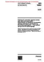
Reinforced branch connection A reinforced branch shall be made with a reinforcement plate (see Fig. 1) or alternatively using thicker wall in branch pipe. The dimensions of reinforcement plates are presented in Standard 313-014. The wall thickness of the reinforcement plate must not exceed s in the calculations.
Fig. 1
Reinforced-branch connection
PIPING STANDARDS GENERAL SELECTION OF TEE CONNECTION TYPES
2.3
9HX191450-L0008 39(259)
No: 301-090 2(2) 14.11.2014
Selection procedures The maximum pressure in the line at the location of the tee connection shall be used as the design pressure of the tee connection. The maximum design pressure at the pressure side of the pump can be defined by adding the head of the pump to the hydrostatic head. The maximum design pressure of the tee connection at the suction side of a pump is maximum hydrostatic head. A reinforced branch with thick wall pipe or plate reinforcement shall be used if pressure strength can be achieved with reinforcement, otherwise a factory-made tee shall be selected. External loads such as vibrations and big bending moments shall be considered when necessary.
3
CARBON STEEL PIPES Branch connections shall be used generally except if DN2/ DN1 = 1. A reinforced branch shall be made with a reinforcement plate or alternatively using thicker wall in branch pipe. Pressure strength of the branch connections and tees shall be checked case by case. For high pressure piping tee-piece shall be selected. Tee pieces with DN2/ DN1 > 0.8 are not permissible for a design within the creep range of the material. For instrumentation connection a reinforced branch connection shall be selected. See the instrumentation standards.
4
GRP PIPES Tee-piece shall be specified for tee connections where the size of the branch pipe is equal or up to two DN sizes smaller than the main pipe. Otherwise reinforced branches shall be used.
PIPING STANDARDS
2
AUSTENITIC STAINLESS STEEL PIPING
9HX191450-L0008 40(259)
PIPING STANDARDS AUSTENITIC STAINLESS STEEL PIPING CONTENT
310-001
Pipe classes 0H...63H
310-002
Allowable pressures at elevated temperatures
310-010
Pipes for pipe classes 6H...63H
310-011
Vacuum pipes, pipe class 0H
311-010
Elbows for pipe classes 0H...63H
312-010
Reducers for pipe classes 0H...63H
313-011
Tee pieces for pipe classes 0H...63H
313-012
Reinforced branch connections – allowable pressures
313-014
Reinforced branch connection with plate
314-010
Summary of collars
315-010
Summary of flanges
316-010
Blank flange 0H...25H
317-010
Spade blank
317-011
Open spade
317-012
Plate valve
320-012
Drain and spooling connection DN 40 and DN 50
320-015
Vent connection DN 25
320-020
Sample taking connection DN 40
9HX191450-L0008 41(259)
1(2) 14.11.2014
PIPING STANDARDS AUSTENITIC STAINLESS STEEL PIPING PIPE CLASSES 0H…63H
1
9HX191450-L0008 42(259)
No: 310-001 1(5) 14.11.2014
GENERAL This standard presents dimension standards and material specifications for piping components of normal austenitic stainless steel pipe classes.
2
PIPE CLASSES Pipe class
0H1A 0H2A 0H3A
6H1A 6H2A 6H3A
10H1A 10H2A 10H3A 10H5A
16H1A 16H2A 16H3A 16H5A
25H1A 25H2A 25H3A
40H1A 40H2A 40H3A
63H1A 63H2A 63H3A
0 (abs)
0.6
1.0
1.6
2.5
4.0
6.3
Design pressure1) 2) (MPa) at 20 °C
1) Design pressure is internal overpressure (pe), except for pipe classes 0H where design pressure 0 refers to absolute pressure = 0.1 MPa external pressure (full vacuum). 2) For elevated temperatures see k coefficients in standard 310-002.
PIPING STANDARDS AUSTENITIC STAINLESS STEEL PIPING PIPE CLASSES 0H…63H
3
9HX191450-L0008 43(259)
No: 310-001 2(5) 14.11.2014
PIPING COMPONENTS FOR 0H1A...63H1A
Piping components
Dimension standard
Material
Remarks
Designation
Standard
Certificate
1.4307
EN 10217-7
3.1
1.4307
EN 10217-7
3.1
1.4307
EN 10253-4
3.1
1.4307
EN 10253-4
3.1
1.4307
EN 10253-4
3.1
1.4307
EN 10028-7
3.1
P265GH
EN 10028-2
3.1
P265GH/
EN 10028-2/ EN 10028-7
3.1
EN 10028-2/ EN 10028-7
3.1
1.4307 lining plate
EN 10204Pipe
EN 10217-7,
Vacuum pipe
EN 10217-7,
310-010 310-011 Elbow
EN 10253-4, 311-010
Reducer
EN 10253-4, 312-010
Tee piece
EN 10253-4, 313-011
Collar
EN 1092-1, PN 10 3) 314-010
Flange
EN 1092-1, PN 10 3) 315-010
Hot dip galvanized for loose flanges
Blank flange
Blank and open spade
EN 1092-1, PN 10
3)
316-010
1.4307 lining plate
317-010
P265GH/
3.1
Hot dip galvanized
3.1
Plate valve
317-012
1.4307
EN 10217-7
3.1
Cap
EN 10253-4,
1.4307
EN 10253-4
3.1
Wallthickness same as pipe wallthickness Hex head bolt 4)
ISO 4014
Strength class 8.8
2.2
Hot dip galvanized
Nut 4)
ISO 4032
Strength class 8
2.2
Hot dip galvanized
Washer
ISO 7089 Gr. A
S 235JR
Gasket
EN 1514-1 Type IBC PN 10 1) 3)
2)
Threaded fittings
EN 10241
1.4404
EN 10025-2
Hot dip galvanized
EN 10272
Thread according to ISO 7-1 Not for 40H1 and 63H1
1) Gasket thickness 2.0 mm 2) Gasket material depends on flow substance. See 9HX191450-L0007 “Technical Specification for Piping Materials and Valve Selection” .. 3) For pipe classes 16H and above the PN corresponds to the pressure class of the piping (e.g. for pipe class 25H the gasket is EN 15141, PN25). 4) Material for hexagon head bolts in pipe class 63H1A is 25CrMo4 and nuts C35E according to EN 10269.
PIPING STANDARDS AUSTENITIC STAINLESS STEEL PIPING PIPE CLASSES 0H…63H
4
9HX191450-L0008 44(259)
No: 310-001 3(5) 14.11.2014
PIPING COMPONENTS FOR 0H2A...63H2A
Piping components
Dimension standard
Remarks
Material Designation
Standard
Certificate EN 10204-
Pipe
EN 10217-7,
1.4404
EN 10217-7
3.1
1.4404
EN 10217-7
3.1
1.4404
EN 10253-4
3.1
1.4404
EN 10253-4
3.1
1.4404
EN 10253-4
3.1
1.4404
EN 10028-7
3.1
P265GH
EN 10028-2
3.1
P265GH/
EN 10028-2/ EN 10028-7
3.1
EN 10028-2/ EN 10028-7
3.1
1.4404 lining plate
310-010 Vacuum pipe
EN 10217-7, 310-011
Elbow
EN 10253-4, 311-010
Reducer
EN 10253-4, 312-010
Tee piece
EN 10253-4, 313-011
Collar
EN 1092-1, PN 10 3) 314-010
Flange
EN 1092-1, PN 10 3) 315-010
Blank Flange
316-010, PN 10 3)
for loose flanges 1.4404 lining plate
Blank and open spade
317-010
Hot dip galvanized
P265GH/
Hot dip galvanized
3.1 3.1
Plate valve
317-012
1.4404
EN 10217-7
3.1
Cap
EN 10253-4,
1.4404
EN 10253-4
3.1
Wallthickness same as pipe wallthickness Hex head bolt 4)
ISO 4014
Strength class 8.8
2.2
Hot dip galvanized
Nut 4)
ISO 4032
Strength class 8
2.2
Hot dip galvanized
Washer
ISO 7089 Gr. A
S 235JR
Gasket
EN 1514-1 Type IBC PN10-63 1) 3)
2)
Threaded fittings
EN 10241
1.4404
EN 10025-2
Hot dip galvanized
EN 10272
Thread according to ISO 7-1 Not for 40H1 and 63H1
1) Gasket thickness 2.0 mm 2) Gasket material depends on flow substance. See 9HX191450-L0007 “Technical Specification for Piping Materials and Valve Selection” 3) For pipe classes 16H and above the PN corresponds to the pressure class of the piping (e.g. for pipe class 25H the gasket is EN 15141 PN25). 4) Material for hexagon head bolts in pipe class 63H1A is 25CrMo4 and nuts C35E according to EN 10269.
PIPING STANDARDS AUSTENITIC STAINLESS STEEL PIPING PIPE CLASSES 0H…63H
5
9HX191450-L0008 45(259)
No: 310-001 4(5) 14.11.2014
PIPING COMPONENTS FOR 0H3A...63H3A
Piping components
Material
Dimension standard
Designation
Remarks Standard
Certificate EN 10204-
Pipe Vacuum pipe Elbow
Reducer Tee piece Collar Flange
EN 10217-7,
1.4462
310-010
(duplex)
EN 10217-7
3.1
EN 10217-7,
1.4462
310-011
(duplex)
EN 10217-7
3.1
EN 10253-4,’
1.4462
311-010
(duplex)
EN 10253-4
3.1
EN 10253-4,
1.4462
312-010
(duplex)
EN 10253-4
3.1
EN 10253-4,
1.4462
313-011
(duplex)
EN 10253-4
3.1
EN 1092-1, PN 10 3)
1.4462
314-010
(duplex)
EN 10028-7
3.1
EN 1092-1, PN 10 3)
P265GH
EN 10028-2
3.1
P265GH/
EN 10028-2/ EN 10028-7
3.1
EN 10028-2/ EN 10028-7
3.1
EN 10217-7
3.1
EN 10253-4
3.1
315-010 Blank flange
316-010, PN 10
Hot dip galvanized for loose flanges
3)
1.4462 lining plate
Hot dip galvanized
3.1
(duplex) Blank and open spade
317-010
P265GH/ 1.4462
3.1
(duplex) Plate valve
317-012
1.4462
Cap
EN 10253-4
1.4462
Wallthickness same as pipe wallthickness
(duplex)
Hex head bolt
ISO 4014
Strength class 8.8
2.2
Hot dip galvanized
Nut
ISO 4032
Strength class 8
2.2
Hot dip galvanized
Washer
ISO 7089 Gr. A
S 235JR
Gasket
EN 1514-1 Type IBC PN16-25 1) 3)
2)
Threaded fittings
EN 10241
1.4462 or equal
(duplex)
EN 10025-2
Hot dip galvanized
EN 10272
Thread according to ISO 7-1 Not for 40H1 and 63H1
1) Gasket thickness 2.0 mm 2) Gasket material depends on flow substance. See 9HX191450-L0007 “Technical Specification for Piping Materials and Valve Selection” 3) For pipe classes 16H and above the PN of the gasket corresponds to the pressure class of the piping (e.g. for pipe class 25H the gasket is EN 1514-1, PN25).
PIPING STANDARDS AUSTENITIC STAINLESS STEEL PIPING PIPE CLASSES 0H…63H
6
9HX191450-L0008 46(259)
No: 310-001 5(5) 14.11.2014
PIPING COMPONENTS FOR 10H5A...16H5A
Piping components
Dimension standard
Remarks
Material Designation 5)
Standard 5)
EN 10217-7,
1.4547
EN 10217-7
3.1
310-010
(AVESTA 254SMO)
EN 10217-7,
1.4547
EN 10217-7
3.1
310-011
(AVESTA 254SMO)
EN 10253-4,
1.4547
EN 10253-4
3.1
311-010
(AVESTA 254SMO)
EN 10253-4,
1.4547
EN 10253-4
3.1
312-010
(AVESTA 254SMO)
EN 10253-4,
1.4547
EN 10253-4
3.1
313-011
(AVESTA 254SMO)
EN 1092-1, PN 10 3)
1.4547
EN 10028-7
3.1
314-010
(AVESTA 254SMO)
EN 1092-1, PN 10 3)
P265GH
EN 10028-2
3.1
P265GH/
EN 10028-2/ EN 10217-7
3.1
EN 10028-2/ EN 10028-7
3.1
EN 10217-7
3.1
EN 10253-4
3.1
Certificate EN 10204-
Pipe Vacuum pipe Elbow Reducer Tee piece Collar Flange
315-010 Blank flange
316-010, PN 10
Hot dip galvanized for loose flanges
3)
1.4547
Hot dip galvanized
(AVESTA 254SMO) Blank and open spade
317-010
P265GH/ 1.4547 lining, 2 mm (AVESTA 254SMO)
Plate valve
317-012
1.4547 (AVESTA 254SMO)
Cap
EN 10253-4,
1.4547
Wallthickness same as pipe wallthickness
(AVESTA 254SMO)
Hex head bolt
ISO 4014
Strength class 8.8
2.2
Hot dip galvanized
Nut
ISO 4032
Strength class 8
2.2
Hot dip galvanized
Washer
ISO 7089 Gr. A
S 235JR
Gasket
EN 1514-1 Type IBC PN10-16 1) 3)
2)
Threaded fittings
EN 10241
1.4547 or equal
EN 10025-2
Hot dip galvanized
EN 10272
Thread according to ISO 7-1 Not for 40H1 and 63H1
1) Gasket thickness 2.0 mm 2) Gasket material depends on flow substance. See 9HX191450-L0007 “Technical Specification for Piping Materials and Valve Selection” 3) For pipe class 16H the PN of the gasket corresponds to the pressure class of the piping (e.g. for pipe class16H the gasket is EN 15141, PN 16).
PIPING STANDARDS AUSTENITIC STAINLESS STEEL PIPING ALLOWABLE PRESSURES AT ELEVATED TEMPERATURES
1
9HX191450-L0008 47(259)
No: 310-002 1(2) 14.11.2014
GENERAL This standard gives the coefficient k for defining the allowable pressures at elevated temperatures generally for pipe classes and in detail for branch connections presented in standards 313-012.
2
LIMITATIONS The allowable pressure shall not exceed the nominal pressure of pipe classes 6H...63H.
3
COEFFICIENT k Temperature o C 1.4307 1 0.93 0.89 0.84 0.80 0.75 0.72 0.68
20 50 75 100 125 150 175 200 where
4
Coefficient k for material grades 1.4404 1 0.96 0.92 0.88 0.84 0.80 0.77 0.74
1.4462 1 0.92 0.86 0.80 0.77 0.74 0.72 0.69
1.4307 corresponds to H1 1.4404 corresponds to H2 1.4462 corresponds to H3
EXAMPLES Example 1: Pipe class 25H2A Temperature = 150 C Coefficient k = 0.8 The allowable pressure = 0.8 x 25 bar = 20 bar, which means that all components of that Pipe class 25H2A stand the pressure 2.0 MPa.
PIPING STANDARDS AUSTENITIC STAINLESS STEEL PIPING ALLOWABLE PRESSURES AT ELEVATED TEMPERATURES
9HX191450-L0008 48(259)
No: 310-002 2(2) 14.11.2014
Example 2: Pipe class 6H1A Temperature = 20 C Coefficient k = 1.00 The allowable pressure = 1.00 x 6 bar = 6.0 bar, which means that the Pipe class can be used up to 0.6 MPa. Example 3: Reinforced branch connection with plate reinforcement of Pipe class 16H2A, DN 800/ DN 500 Temperature = 150 C Coefficient k = 0,80 Allowable pressure from standard 313-012 is 1,75 MPa The allowable pressure = 0.8 x 1,75 MPa = 1,40 MPa, which means that the reinforced branch connection stands the pressure 1,40 MPa.
PIPING STANDARDS AUSTENITIC STAINLESS STEEL PIPING PIPES FOR PIPE CLASSES 6H...63H
1
9HX191450-L0008 49(259)
No: 310-010 1(1) 14.11.2014
DIMENSIONS DN
Do x s 0H
1),
10H
16H
25H
40H
63H
6H 6
10.2 x 1.6
10
17.2 x 1.6
According to
15
21.3 x 1.6
6H
20
26.9 x 1.6
25
33.7 x 1.6
(32)
42.4 x 1.6
40
48.3 x 1.6
According
50
60.3 x 1.6
to
60.3 x 2.0
(65)
76.1 x 1.6
6H
76.1 x 2.6
80
88.9 x 2.0
According to
100
114.3 x 2.0
6H
(125)
139.7 x 2.0
150
168.3 x 2.0
200
219.1 x 2.0
250
273 x 2.0
300 350
According to 6H According to 6H
88.9 x 3.2 114.3 x 2.6
114.3 x 4.0
139.7 x 3.2
139.7 x 5.0
168.3 x 2.6
168.3 x 4.0
168.3 x 6.3
219.1 x 3.2
219,1 x 5.0
273 x 2.6
273 x 4.0
273 x 6.3
323.9 x 2.6
323.9 x 3.2
323.9 x 5.0
355.6 x 2.6
355.6 x 3.2
355.6 x 5.0
400
406.4 x 3.2
406.4 x 4.0
406.4 x 6.3
(450)
457 x 3.2
457 x 5.0
457 x 8.0
500
508 x 4.0
508 x 6.3
508 x 10
600
610 x 4.0
610 x 5.0
610 x 8.0
610 x 12.5
700
711 x 4.0
711 x 5.0
711 x 8.0
711 x 12.5
800
813 x 4.0
813 x 6.3
813 x 10
813 x 12.5
900
914 x 4.0
914 x 8.0
914 x 10
1000
1016 x 5.0
1016 x 8.0
1016 x 12,5
1200
1220 x 6.3
1220 x 10
The nominal sizes inside parenthesis shall be avoided. 1) Reinforcement rings against vacuum are presented in the standard 310-011. 2) Additional nominal sizes have to be specified case by case. 2
DESIGNATION Name, Do x s, material, standard No. Example: Pipe, 114.3 x 2, 1.4404, EN 10217-7
PIPING STANDARDS AUSTENITIC STAINLESS STEEL PIPING
9HX191450-L0008 50(259)
VACUUM PIPES, PIPE CLASS 0H
1
No: 310-011 1(2) 14.11.2014
DIMENSIONS
DN
Do
s
Lmax
bxh
200
219.1
2.0
2000
20 x 6
250
273
2.0
1700
25 x 6
300
323.9
2.6
2200
30 x 6
350
355.6
2.6
2300
35 x 8
400
406.4
3.2
2800
40 x 8
(450)
457
3.2
2800
40 x 8
500
508
4.0
3500
50 x 8
600
610
4.0
2600
60 x 6
700
711
4.0
2300
60 x 6
800
813
4.0
1700
60 x 6
900
914
4.0
1500
60 x 6
1000
1016
5.0
2200
70 x 8
1200
1220
6.3
2900
90 x 8
Notes: The effective throat thickness of fillet weld for the reinforcement ring is 0.7 x s, were s is the wall thickness of the pipe. Length of the welds on both sides of the ring must be at least 0.5 x circumference of the pipe. When using intermittent weld, the distance between welds must not exceed 8 x wall thickness of the pipe.
PIPING STANDARDS AUSTENITIC STAINLESS STEEL PIPING VACUUM PIPES, PIPE CLASS 0H
9HX191450-L0008 51(259)
No: 310-011 2(2) 14.11.2014
Nominal sizes DN 6 - DN 150 do not need the reinforcement rings against vacuum when the wall thicknesses are according to the pipe class 6H. Extra reinforcement rings must be welded on to the pipe at both ends near bends. 2
DESIGNATION Name, Do x s, material, standard No. Example: Vacuum pipe, 406.4 x 3.2, 1.4404, 310-011
PIPING STANDARDS AUSTENITIC STAINLESS STEEL PIPING
9HX191450-L0008 52(259)
ELBOWS FOR PIPE CLASSES 0H...63H
1
Table 1
No: 311-010 1(2) 14.11.2014
DIMENSIONS
Dimensions according to pipe classes Do x s
R
DN
Type
6
0H 6H 10.2 x 2.0
10 15 20 25 (32) 40 50 (65) 80 100 (125) 150 200 250 300 350 400 (450) 500 600 700 800 900 1000 1200
17.2 x 2.0 21.3 x 2.0 26.9 x 2.0 33.7 x 2.0 42.4 x 2.0 48.3 x 2.0 60.3 x 2.0 76.1 x 2.0 88.9 x 2.0 114.3 x 2.0 139.7 x 2.0 168.3 x 2.0 219.1 x 2.0 273 x 2.0 323.9 x 2.6 355.6 x 2.6 406.4 x 3.2 457 x 3.2 508 x 4.0 610 x 4.0 711 x 5.0 813 x 5.0 914 x 5.0 1016 x 6.3 1220 x 8.0
10H
16H
25H
1.5D
2.5D
R = 3...5D
According to 6H
According to 6H
According to 6H
273 x 2.6 323.9 x 3.2 355.6 x 3.2 406.4 x 4.0 457 x 4.0 508 x 5.0 610 x 6.3 711 x 6.3 813 x 8.0 914 x 8.0 1016 x 10 1220 x 12.5
168.3 x 2.6 219.1 x 3.2 273 x 4.0 323.9 x 4.0 355.6 x 4.0 406.4 x 5.0 457 x 6.3 508 x 8.0 610 x 10.0 711 x 10.0 813 x 12.5 914 x 12.5 1016 x 12.5
114.3 x 2.6 139.7 x 3.2 168.3 x 4.0 219.1 x 5.0 273 x 6.3 323.9 x 6.3 355.6 x 6.3 406.4 x 8.0 457 x 10 508 x 12.5 610 x 12.5 711 x 12.5 813 x 14.2
38 28 29 38 48 57 76 95 114 152 190 229 305 381 457 533 610 686 762 914 1067 1219 1372 1524 1830
Elbow or bent pipe 45 57 72 93 108 135 175 205 270 330 390 510 650 775 850 970 1122 1245 1524
R = 1.5D Pressed elbow
R = 1.5D Mitre elbow
PIPING STANDARDS AUSTENITIC STAINLESS STEEL PIPING
9HX191450-L0008 53(259)
ELBOWS FOR PIPE CLASSES 0H...63H
No: 311-010 1(2) 14.11.2014
Do x s
DN 40H
R
Type
3...5D
Bent
63H According to
10
17.2 x 1.6
15
21.3 x 2.0
20
26.9 x 2.0
pipe
25
33.7 x 2.0
or elbow
(32)
42.4 x 2.0
42.4 x 3.2
48
40
48.3 x 2.0
48.3 x 3.2
57
50
60.3 x 2.6
60.3 x 4.0
76
(65)
76.1 x 3.2
76.1 x 5.0
95
80
88.9 x 3.2
88.9 x 5.0
114
100
114.3 x 5.0
114.3 x 6.3
152
(125)
139.7 x 5.0
139.7 x 6.3
190
150
168.3 x 6.3
168.3 x 8.0
229
200
219.1 x 8.0
305
250
273 x 10.0
381
40H
R = 1.5D
Pressed elbow
The nominal sizes inside parenthesis shall be avoided. 2
DESIGNATION Name, Do x s, R, material, standard No. Example: Elbow, 219.1 x 2.0, 305, 1.4404, EN 10253-4
PIPING STANDARDS AUSTENITIC STAINLESS STEEL PIPING
9HX191450-L0008
REDUCERS FOR PIPE CLASSES 0H...63H
No: 312-010 1(5) 14.11.2014
1
54(259)
DIMENSIONS See the following table for dimensions.
L = 2.96 x (Do1 - Do2) 2
SUDDEN REDUCER Sudden reducer, type S, to be used for pulp on suction side of a pump when consistency C is 4 %. Design of sudden reducer shall be verified with strength calculations by the Supplier. The given plate thickness of 6 mm is minimum requirement.
PIPING STANDARDS AUSTENITIC STAINLESS STEEL PIPING
9HX191450-L0008
REDUCERS FOR PIPE CLASSES 0H...63H
No: 312-010 2(5) 14.11.2014
Type S
55(259)
PIPING STANDARDS AUSTENITIC STAINLESS STEEL PIPING
9HX191450-L0008
REDUCERS FOR PIPE CLASSES 0H...63H
No: 312-010 3(5) 14.11.2014
3
56(259)
DIMENSIONS FOR PIPE CLASSES 0H...63H DN1
DN2
Do1
Do2
Wall thickness s
L 0H 6H
10H
16H
25H
40H
63H
According
According
to 6H
to 6H
According to 6H
25
10 15 20
33.7
17.2 21.3 26.9
49 37 20
2.0 2.0 2.0
(32)
10 15 20 25
42.4
17.2 21.3 26.9 33.7
75 62 46 26
2.0 2.0 2.0 2.0
15 20 25 32
48.3
21.3 26.9 33.7 42.4
80 63 43 17
2.0 2.0 2.0 2.0
50
20 25 32 40
60.3
26.9 33.7 42.4 48.3
99 79 53 36
2.0 2.0 2.0 2.0
(65)
25 32 40 50
76.1
33.7 42.4 48.3 60.3
12 6 10 0 82 47
2.0 2.0 2.0 2.0
2.6 2.6 2.6 2.6
4.0 4.0 4.0 4.0
80
32 40 50 (65)
88.9
42.4 48.3 60.3 76.1
13 8 12 0 84 38
2.0 2.0 2.0 2.0
2.6 2.6 2.6 2.6
4.0 4.0 4.0 4.0
100
40 50 (65) 80
114.3
48.3 60.3 76.1 88.9
19 5 16 0 113 75
2.0 2.0 2.0 2.0
2.6 2.6 2.6 2.6
3.2 3.2 3.2 3.2
5.0 5.0 5.0 5.0
(125 )
50 (65) 80 100
139. 7
60.3 76.1 88.9 114.3
23 5 18 8 15 1 75
2.0 2.0 2.0 2.0
2.6 2.6 2.6 2.6
4.0 4.0 4.0 4.0
6.3 6.3 6.3 6.3
150
(65) 80 100 (125 )
168. 3
76.1 88.9 114.3 139. 7
27 3 23 5 16 0 85
2.0 2.0 2.0 2.0
3.2 3.2 3.2 3.2
5.0 5.0 5.0 5.0
8.0 8.0 8.0 8.0
40
According
According
to 6H
to 6H
2.6 2.6 2.6 2.6 3.2 3.2 3.2 3.2
PIPING STANDARDS AUSTENITIC STAINLESS STEEL PIPING
9HX191450-L0008
REDUCERS FOR PIPE CLASSES 0H...63H
No: 312-010 4(5) 14.11.2014
DN1
DN2
Do1
Do2
L
57(259)
Wall thickness s 0H
10H
16H
25H
40H
63H
2.6 2.6 2.6 2.6
4.0 4.0 4.0 4.0
6.3 6.3 6.3 6.3
10 10 10 10
3.2 3.2 3.2 3.2
5.0 5.0 5.0 5.0
8.0 8.0 8.0 8.0
10 10 10 10
6H 200
80 100 (125 ) 150
219.1
88.9 114.3 139.7 168.3
385 310 235 150
2.0 2.0 2.0 2.0
250
100 (125 ) 150 200
273.0
114.3 139.7 168.3 219.1
470 395 310 160
2.0 2.0 2.0 2.0
300
(125 ) 150 200 250
323.9
139.7 168.3 219.1 273.0
545 461 310 151
2.6 2.6 2.6 2.6
3.2 3.2 3.2 3.2
5.0 5.0 5.0 5.0
10 10 10 10
350
150 200 250 300
355.6
168.3 219.1 273.0 323.9
554 404 244 94
2.6 2.6 2.6 2.6
4.0 4.0 4.0 4.0
5.0 5.0 5.0 5.0
10 10 10 10
400
200 250 300 350
406.4
219.1 273.0 323.9 355.6
554 395 244 150
3.2 3.2 3.2 3.2
4.0 4.0 4.0 4.0
6.3 6.3 6.3 6.3
10 10 10 10
(450 )
250 300 350 400
457.0
273.0 323.9 355.6 406.4
545 395 301 150
4.0 4.0 4.0 4.0
6.3 6.3 6.3 6.3
10 10 10 10
500
300 350 400 (450 )
508.0
323.9 355.6 406.4 457.0
545 451 301 150
4.0 4.0 4.0 4.0
5.0 5.0 5.0 5.0
6.3 6.3 6.3 6.3
10 10 10 10
600
350 400 (450 ) 500
610.0
355.6 406.4 457.0 508.0
752 601 451 301
4.0 4.0 4.0 4.0
5.0 5.0 5.0 5.0
8.0 8.0 8.0 8.0
12,5 12,5 12,5 12,5
700
400 (450 ) 500 600
711.0
406.4 457.0 508.0 610.0
902 752 601 301
4.0 4.0 4.0 4.0
6.3 6.3 6.3 6.3
10.0 10.0 10.0 10.0
12,5 12,5 12,5 12,5
800
(450 ) 500 600 700
813.0
457.0 508.0 610.0 711.0
105 3 902 601 301
5.0 5.0 5.0 5.0
6.3 6.3 6.3 6.3
10.0 10.0 10.0 10.0
12,5 12,5 12,5 12,5
900
500 600 700 800
914.0
508.0 610.0 711.0 813.0
120 3 902 601 301
5.0 5.0 5.0 5.0
8.0 8.0 8.0 8.0
12,5 12,5 12,5 12,5
1000
600 700 800
1016.0
610.0 711.0 813.0
120 3 902
6.3 6.3 6.3
8.0 8.0 8.0
12,5 12,5 12,5
According
to 6H
PIPING STANDARDS AUSTENITIC STAINLESS STEEL PIPING 900 1200
700 800 900 1000
1220. 0
9HX191450-L0008 58(259)
914.0
601 301
6.3
8.0
711.0 813.0 914.0 1016.0
150 6 120 5 905 604
6.3 6.3 6.3 6.3
10.0 10.0 10.0 10.0
12,5
PIPING STANDARDS AUSTENITIC STAINLESS STEEL PIPING
9HX191450-L0008
REDUCERS FOR PIPE CLASSES 0H...63H
No: 312-010 5(5) 14.11.2014
59(259)
Note: The wall thickness of reducer is at least the same as the wall thicknesses of the pipe at the bigger end of the reducer, however at least 2 mm. 4
DESIGNATION Name, type, DN1/ DN2 x s, material, standard No. Example 1: Reducer, C, 500/ 350 x 4.0, 1.4404, EN 10253-4 Example 2: Reducer, S, 500/ 350 x 4.0, 1.4404, 312-010
PIPING STANDARDS AUSTENITIC STAINLESS STEEL PIPING TEE PIECES FOR PIPE CLASSES 0H...63H
1
DIMENSIONS
Dimensions are according to Table 1.
9HX191450-L0008 60(259)
No: 313-011 1(4) 14.11.2014
PIPING STANDARDS AUSTENITIC STAINLESS STEEL PIPING
9HX191450-L0008 61(259)
TEE PIECES FOR PIPE CLASSES 0H...63H
No: 313-011 2(4) 14.11.2014
Table 1 DN1
DN2
Do1
Do2
L
0H
10H
16H
25H
40H
63H
6H s1 / s2
s1 / s2
s1 / s2
s1 / s2
s1 / s2
s1 / s2
(32)
32
42.4
42.4
48
2.0 2.0
2.0 2.0
2.0 2.0
2.0
2.0
2.0
2.0
2.6
2.6
(32)
25
42.4
33.7
48
2.0 2.0
2.0 2.0
2.0 2.0
2.0
2.0
2.0
2.0
2.6
2.0
40
40
48.3
48.3
57
2.0 2.0
2.0 2.0
2.0 2.0
2.0 2.0
2.0 2.0
3.2
3.2
40
32
48.3
42.4
57
2.0 2.0
2.0 2.0
2.0 2.0
2.0 2.0
2.0 2.0
3.2
2.0
50
50
60.3
60.3
125
2.0 2.0
2.0 2.0
2.0 2.0
2.0 2.0
2.6
2.6
4.0
4.0
50
40
60.3
48.3
125
2.0 2.0
2.0 2.0
2.0 2.0
2.0 2.0
2.6
2.0
4.0
2.0
(65)
65
76.1
76.1
140
2.0 2.0
2.0 2.0
2.0 2.0
2.6
2.6
3.2
3.2
5.0
5.0
(65)
50
76.1
60.3
140
2.0 2.0
2.0 2.0
2.0 2.0
2.6
2.0
3.2
2.6
5.0
2.6
80
80
88.9
88.9
150
2.0 2.0
2.0 2.0
2.0 2.0
2.6
2.6
4.0
4.0
5.0
5.0
80
(65)
88.9
76.1
150
2.0 2.0
2.0 2.0
2.0 2.0
2.6
2.0
4.0
2.6
5.0
4.0
100
100
114.3
114.3
160
2.0 2.0
2.0 2.0
2.6
2.6
3.2
3.2
5.0
5.0 6.3
6.3
100
80
114.3
88.9
160
2.0 2.0
2.0 2.0
2.6
2.0
3.2
2.6
5.0
3.2 6.3
5.0
(125)
125
139.7
139.7
180
2.0 2.0
2.0 2.0
3.2
3.2
4.0
4.0
6.3
6.3
8.0
8.0
(125)
100
139.7
114.3
180
2.0 2.0
2.0 2.0
3.2
2.0
4.0
3.2
6.3
4.0
8.0
6.3
150
150
168.3
168.3
200
2.0 2.0
2.6
2.6
4.0
4.0
5.0
5.0 8.0
8.0
10.0 10.0
150
(125)
168.3
139.7
200
2.0 2.0
2.6
2.0
4.0
2.0
5.0
4.0 8.0
4.0
10.0
200
200
219.1
219.1
250
2.6 2.6
3.2
3.2
5.0
5.0
6.3
6.3
10.0 10.0
200
150
219.1
168.3
250
2.6 2.0
3.2
2.6
5.0
2.6
6.3
5.0
10.0
250
250
273.0
273.0
300
2.6 2.6
4.0
4.0
6.3
6.3
8.0
8.0
12.5 12.5
250
200
273.0
219.1
300
2.6 2.6
4.0
3.2
6.3
3.2
8.0
6.3
12.5
300
300
323.9
323.9
330
3.2 3.2
5.0
5.0 6.3
6.3
10.0 10.0
300
250
323.9
273.0
330
3.2 2.6
5.0
4.0 6.3
5.0
10.0
350
350
355.6
355.6
360
4.0
4.0
5.0
5.0 8.0
8.0
10.0 10.0
350
300
355.6
323.9
360
4.0
3.2
5.0
5.0 8.0
6.3
10.0 10.0
6.3
5.0
8.0
8.0
PIPING STANDARDS AUSTENITIC STAINLESS STEEL PIPING
9HX191450-L0008 62(259)
TEE PIECES FOR PIPE CLASSES 0H...63H
No: 313-011 3(4) 14.11.2014
Table 1 (continues) DN1
DN2
Do1
Do2
L
0H
10H
16H
25H
s1 / s2
s1 / s2
s1 / s2
6H s1 / s2 400
400
406.4
406.4
400
4.0
4.0
6.3
6.3
8.0
8.0
12.5
12.5
400
350
406.4
355.6
400
4.0
4.0
6.3
5.0
8.0
8.0
12.5
10.0
(450)
450
457.0
457.0
450
5.0
5.0
6.3
6.3
10.0 10.0
12.5
12.5
(450)
400
457.0
406.4
450
5.0
4.0
6.3
6.3
10.0
8.0
12.5
12.5
500
500
508.0
508.0
500
5.0
5.0
8.0
8.0
10.0 10.0
14.2
14.2
500
(450)
508.0
457.0
500
5.0
5.0
8.0
6.3
10.0 10.0
14.2
12.5
600
600
610.0
610.0
600
6.3
6.3
10.0
10.0
12.5 12.5
17.5
17.5
600
500
610.0
508.0
600
6.3
5.0
10.0
6.3
12.5 10.0
17.5
14.2
700
700
711.0
711.0
700
8.0
8.0
10.0
10.0
14.2 14.2
20.0
20.0
700
600
711.0
610.0
700
8.0
5.0
10.0
10.0
14.2 12.5
20.0
16.0
800
800
813.0
813.0
800
8.0
8.0
12.5
12.5
16.0 16.0
20.0
20.0
800
700
813.0
711.0
800
8.0
8.0
12.5
10.0
16.0 14.2
20.0
20.0
900
900
914.0
914.0
900
10.0 10.0
12.5
12.5
16.0 16.0
900
800
914.0
813.0
900
10.0
8.0
12.5
12.5
16.0 16.0
1000
1000
1016.0
1016.0
1000
10.0 10.0
14.2
14.2
20.0 20.0
1000
900
1016.0
914.0
1000
10.0 10.0
14.2
12.5
20.0 16.0
1200
1200
1220.0
1220.0
1200
12.5 12.5
1200
1000
1220.0
1016
1200
12.5 12.5
PIPING STANDARDS AUSTENITIC STAINLESS STEEL PIPING TEE PIECES FOR PIPE CLASSES 0H...63H
2
DESIGNATION Name, DN1/ DN2, s1/s2, material, standard No. Example: Tee piece, 200/ 200, 3.2/ 3.2, 1.4404, EN 10253-4
9HX191450-L0008 63(259)
No: 313-011 4(4) 14.11.2014
PIPING STANDARDS AUSTENITIC STAINLESS STEEL PIPING REINFORCED BRANCH CONNECTIONS – ALLOWABLE PRESSURES
1
9HX191450-L0008 64(259)
No: 313-012 14.11.2014
GENERAL The allowed pressures for the normal wall thicknesses for each pipe class have been calculated according to EN 13480-3. The pipes are with wall thicknesses according to different pipe classes. The branches are reinforced with plate. See standard 313-014.
2
CALCULATION BASIS Material 1.4404 Temperature t = 20 C Corrosion allowance c o = 0 mm Tolerance allowance c = 10 % however at least ± 0.2 mm for diameters 21...1220 mm Welding factor
z = 1.0
Allowable pressures are presented in MPa 3
TABLES Allowable pressure tables for normal walls of pipe classes: Table 1 Table 2 Table 3 Table 4 Table 5 Table 6
4H and 6H 10H 16H 25H 40H 63H
reinforced-branch connection reinforced-branch connection reinforced-branch connection reinforced-branch connection reinforced-branch connection reinforced-branch connection
PIPING STANDARDS AUSTENITIC STAINLESS STEEL PIPING REINFORCED-BRANCH CONNECTIONSALLOWABLE PRESSURES Table 1 Allowable pressure (MPa) for reinforced-branch connection See standard 301-090, item 2.2 Pipe class 4H and 6H Outside
9HX191450-L0008 65(259)
No: 313-012 2(7) 14.11.2014
Outside diameter of connecting pipe (mm)
diameter main pipe
Wall
48,3
60,3
76,1
88,9
114,3
139,7
168,3
219,1
273,0
323,9
355,6
406,4
457,0
508,0
610,0
711,0
813,0
914,0
1016,0
1220,0
1,6
1,6
1,6
2,0
2,0
2,0
2,0
2,0
2,0
2,6
3,2
3,2
3,2
4,0
4,0
4,0
4,0
4,0
5,0
6,3
48,3
1,6
5,23
60,3
1,6
4,57
3,89
76,1
1,6
3,94
3,38
2,85
88,9
2,0
4,56
3,92
3,31
3,24
114,3
2,0
3,84
3,33
2,84
2,78
2,31
139,7
2,0
3,33
2,91
2,50
2,44
2,04
1,76
168,3
2,0
2,91
2,56
2,21
2,16
1,81
1,57
1,36
219,1
2,0
2,39
2,12
1,84
1,80
1,52
1,33
1,16
0,95
273,0
2,0
2,02
1,80
1,58
1,54
1,31
1,15
1,00
0,83
0,70
323,9
2,6
2,35
2,12
1,87
1,79
1,53
1,34
1,18
0,97
0,82
0,79
355,6
3,2
2,76
2,49
2,22
2,11
1,81
1,59
1,40
1,16
0,98
0,92
0,93
406,4
3,2
2,48
2,25
2,01
1,91
1,65
1,46
1,28
1,06
0,90
0,85
0,86
0,77
457,0
3,2
2,25
2,05
1,84
1,75
1,52
1,34
1,19
0,99
0,84
0,79
0,80
0,72
0,66
508,0
4,0
2,65
2,43
2,20
2,08
1,82
1,62
1,44
1,20
1,02
0,95
0,93
0,84
0,77
0,77
610,0
4,0
2,28
2,10
1,91
1,81
1,60
1,42
1,27
1,07
0,91
0,85
0,83
0,75
0,69
0,69
0,60
711,0
4,0
2,00
1,85
1,69
1,61
1,42
1,28
1,14
0,97
0,83
0,77
0,75
0,68
0,63
0,63
0,54
0,48
813,0
4,0
1,78
1,66
1,52
1,45
1,29
1,16
1,04
0,88
0,76
0,70
0,69
0,63
0,58
0,57
0,50
0,45
0,40
914,0 1016, 0 1220, 0
4,0
1,61
1,50
1,38
1,32
1,18
1,06
0,96
0,82
0,70
0,65
0,64
0,58
0,53
0,53
0,46
0,41
0,37
0,34
5,0
1,88
1,77
1,64
1,56
1,41
1,28
1,16
0,99
0,86
0,79
0,77
0,70
0,64
0,63
0,55
0,49
0,44
0,40
0,40
6,3
2,06
1,95
1,83
1,75
1,59
1,46
1,34
1,16
1,02
0,93
0,90
0,82
0,75
0,72
0,63
0,56
0,51
0,46
0,45
0,43
PIPING STANDARDS AUSTENITIC STAINLESS STEEL PIPING REINFORCED-BRANCH CONNECTIONS ALLOWABLE PRESSURES Table 2 Allowable pressure (MPa) for reinforced-branch connection See standard 301-090, item 2.2 Pipe class 10H Outside
9HX191450-L0008 66(259)
No: 313-012 3(7) 14.11.2014
Outside diameter of connecting pipe (mm)
diameter main pipe
Wall
48,3
60,3
76,1
88,9
114,3
139,7
168,3
219,1
273,0
323,9
355,6
406,4
457,0
508,0
610,0
711,0
813,0
914,0
1016,0
1220,0
1,6
1,6
1,6
2,0
2,0
2,0
2,0
2,0
2,0
2,6
3,2
3,2
3,2
4,0
5,0
5,0
6,3
8,0
8,0
10,0
48,3
1,6
5,23
60,3
1,6
4,57
3,89
76,1
1,6
3,94
3,38
2,85
88,9
2,0
4,56
3,92
3,31
3,24
114,3
2,0
3,84
3,33
2,84
2,78
2,31
139,7
2,0
3,33
2,91
2,50
2,44
2,04
1,76
168,3
2,0
2,91
2,56
2,21
2,16
1,81
1,57
1,36
219,1
2,0
2,39
2,12
1,84
1,80
1,52
1,33
1,16
0,95
273,0
2,0
2,02
1,80
1,58
1,54
1,31
1,15
1,00
0,83
0,70
323,9
2,6
2,35
2,12
1,87
1,79
1,53
1,34
1,18
0,97
0,82
0,79
355,6
3,2
2,76
2,49
2,22
2,11
1,81
1,59
1,40
1,16
0,98
0,92
0,93
406,4
3,2
2,48
2,25
2,01
1,91
1,65
1,46
1,28
1,06
0,90
0,85
0,86
0,77
457,0
3,2
2,25
2,05
1,84
1,75
1,52
1,34
1,19
0,99
0,84
0,79
0,80
0,72
0,66
508,0
4,0
2,65
2,43
2,20
2,08
1,82
1,62
1,44
1,20
1,02
0,95
0,93
0,84
0,77
0,77
610,0
5,0
2,92
2,71
2,47
2,34
2,07
1,86
1,66
1,40
1,20
1,10
1,07
0,96
0,88
0,86
0,82
711,0
5,0
2,56
2,39
2,19
2,08
1,85
1,66
1,50
1,27
1,09
1,00
0,97
0,88
0,80
0,79
0,74
0,66
813,0
6,3
2,95
2,77
2,56
2,44
2,19
1,99
1,80
1,54
1,34
1,22
1,17
1,06
0,97
0,94
0,86
0,77
0,76
914,0 1016, 0 1220, 0
8,0
3,46
3,27
3,05
2,92
2,65
2,42
2,21
1,91
1,67
1,52
1,45
1,32
1,21
1,15
1,05
0,93
0,89
0,89
8,0
3,15
2,99
2,79
2,67
2,43
2,23
2,04
1,77
1,56
1,42
1,35
1,23
1,13
1,08
0,98
0,87
0,84
0,84
0,77
10,0
3,40
3,25
3,07
2,95
2,72
2,52
2,33
2,05
1,81
1,66
1,58
1,45
1,34
1,27
1,14
1,02
0,96
0,94
0,86
0,82
PIPING STANDARDS AUSTENITIC STAINLESS STEEL PIPING REINFORCED-BRANCH CONNECTIONS ALLOWABLE PRESSURES Table 3
9HX191450-L0008 67(259)
No: 313-012 4(7) 14.11.2014
Allowable pressure (MPa) for reinforced-branch connection See standard 301-090, item 2.2 Pipe class 16H
Outside
Outside diameter of connecting pipe (mm)
diameter main pipe
Wall
42,4
48,3
60,3
76,1
88,9
114,3
139,7
168,3
219,1
273,0
323,9
355,6
406,4
457,0
508,0
610,0
711,0
813,0
914,0
1016
1,6
1,6
1,6
1,6
2,0
2,0
2,0
2,0
2,0
2,6
3,2
3,2
4,0
5,0
6,3
8,0
8,0
10,0
10,0
12,5
42,4
1,6
6,21
48,3
1,6
5,75
5,23
60,3
1,6
5,01
4,57
3,89
76,1
1,6
4,29
3,94
3,38
2,85
88,9
2,0
4,95
4,56
3,92
3,31
3,24
114,3
2,0
4,15
3,84
3,33
2,84
2,78
2,31
139,7
2,0
3,59
3,33
2,91
2,50
2,44
2,04
1,76
168,3
2,0
3,13
2,91
2,56
2,21
2,16
1,81
1,57
1,36
219,1
2,0
2,55
2,39
2,12
1,84
1,80
1,52
1,33
1,16
0,95
273,0
2,6
2,86
2,69
2,41
2,11
2,02
1,72
1,50
1,32
1,08
323,9
3,2
3,14
2,97
2,68
2,37
2,25
1,93
1,69
1,49
1,22
1,11
1,06
355,6
3,2
2,91
2,76
2,49
2,22
2,11
1,81
1,59
1,40
1,16
1,05
1,00
0,93
406,4
4,0
3,34
3,18
2,91
2,60
2,46
2,14
1,89
1,67
1,38
1,24
1,15
1,07
1,05
457,0
5,0
3,89
3,72
3,42
3,10
2,92
2,56
2,28
2,02
1,69
1,49
1,37
1,27
1,22
1,22
508,0
6,3
4,59
4,42
4,10
3,74
3,53
3,12
2,80
2,50
2,10
1,84
1,67
1,56
1,47
1,43
1,45
610,0
8,0
5,10
4,93
4,62
4,27
4,05
3,62
3,28
2,96
2,52
2,21
2,00
1,87
1,74
1,67
1,64
1,56
711,0
8,0
4,46
4,32
4,06
3,76
3,58
3,22
2,93
2,65
2,27
2,00
1,82
1,70
1,59
1,52
1,49
1,42
1,26
813,0
10,0
5,04
4,91
4,65
4,34
4,15
3,77
3,46
3,16
2,74
2,42
2,20
2,06
1,92
1,81
1,75
1,63
1,45
1,43
914,0
10,0
4,54
4,42
4,20
3,94
3,77
3,44
3,16
2,90
2,52
2,24
2,03
1,91
1,78
1,69
1,63
1,52
1,35
1,33
1,22
1016,0
12,5
5,24
5,12
4,89
4,62
4,44
4,09
3,79
3,50
3,08
2,75
2,50
2,36
2,19
2,06
1,97
1,81
1,62
1,56
1,42
1,01
1,43
PIPING STANDARDS AUSTENITIC STAINLESS STEEL PIPING REINFORCED-BRANCH CONNECTIONS ALOWABLE PRESSURES Table 4
9HX191450-L0008 68(259)
No: 313-012 5(7) 14.11.2014
Allowable pressure (MPa) for reinforced-branch connection See standard 301-090, item 2.2 Pipe class 25H
Outside
Outside diameter of connecting pipe (mm)
diameter main pipe
Wall
33,7
42,4
48,3
60,3
76,1
88,9
114,3
139,7
168,3
219,1
273,0
323,9
355,6
406,4
457,0
508,0
610,0
711,0
813,0
1,6
1,6
1,6
1,6
1,6
2,0
2,0
2,0
2,6
3,2
4,0
5,0
5,0
6,3
8,0
10,0
12,5
12,5
12,5
33,7
1,6
8,41
42,4
1,6
7,33
6,21
48,3
1,6
6,74
5,75
5,23
60,3
1,6
5,82
5,01
4,57
3,89
76,1
1,6
4,94
4,29
3,94
3,38
2,85
88,9
2,0
5,67
4,95
4,56
3,92
3,31
3,24
114,3
2,0
4,72
4,15
3,84
3,33
2,84
2,78
2,31
139,7
2,0
4,05
3,59
3,33
2,91
2,50
2,44
2,04
1,76
168,3
2,6
4,63
4,15
3,87
3,41
2,95
2,82
2,36
2,04
1,95
219,1
3,2
4,72
4,27
4,02
3,58
3,13
2,96
2,51
2,17
2,03
1,81
273,0
4,0
5,04
4,62
4,37
3,94
3,49
3,28
2,80
2,45
2,26
1,97
1,81
323,9
5,0
5,59
5,18
4,93
4,49
4,01
3,77
3,26
2,87
2,61
2,25
2,04
1,95
355,6
5,0
5,16
4,79
4,57
4,17
3,74
3,52
3,05
2,69
2,46
2,13
1,92
1,84
1,72
406,4
6,3
5,94
5,56
5,33
4,91
4,45
4,19
3,67
3,26
2,97
2,55
2,27
2,13
1,98
1,96
457,0
8,0
6,96
6,56
6,32
5,88
5,38
5,07
4,49
4,03
3,66
3,15
2,78
2,57
2,39
2,31
2,31
508,0
10,0
8,07
7,66
7,41
6,94
6,41
6,07
5,43
4,91
4,47
3,86
3,40
3,10
2,90
2,75
2,69
2,71
610,0
12,5
8,69
8,32
8,09
7,65
7,13
6,79
6,15
5,62
5,16
4,49
3,97
3,61
3,39
3,18
3,06
3,01
2,86
711,0
12,5
7,55
7,25
7,06
6,70
6,27
5,99
5,45
5,01
4,61
4,04
3,59
3,28
3,08
2,89
2,79
2,74
2,60
2,32
813,0
12,5
6,67
6,42
6,26
5,96
5,60
5,36
4,90
4,51
4,17
3,67
3,28
3,00
2,82
2,66
2,56
2,52
2,39
2,14
1,94
PIPING STANDARDS AUSTENITIC STAINLESS STEEL PIPING REINFORCED-BRANCH CONNECTIONS ALOWABLE PRESSURES Table 5
9HX191450-L0008 69(259)
No: 313-012 6 (7) 14.11.2014
Allowable pressure (MPa) for reinforced-branch connection See standard 301-090, item 2.2 Pipe class 40H
Outside
Outside diameter of connecting pipe (mm)
diameter main pipe
Wall
10,2
17,2
21,3
26,9
33,7
42,4
48,3
60,3
76,1
88,9
114,3
139,7
168,3
219,1
273,0
1,6
1,6
1,6
1,6
1,6
1,6
1,6
1,6
1,6
2,0
2,6
3,2
4,0
5,0
6,3
10,2
1,6
40,23
17,2
1,6
28,53
20,28
21,3
1,6
24,36
17,83
15,34
26,9
1,6
20,31
15,30
13,33
11,31
33,7
1,6
16,91
13,07
11,51
9,87
8,41
42,4
1,6
13,95
11,04
9,81
8,51
7,33
6,21
48,3
1,6
12,47
9,99
8,93
7,79
6,74
5,75
5,23
60,3
1,6
10,28
8,39
7,56
6,66
5,82
5,01
4,57
3,89
76,1
1,6
8,35
6,95
6,31
5,61
4,94
4,29
3,94
3,38
2,85
88,9
2,0
9,26
7,82
7,15
6,40
5,67
4,95
4,56
3,92
3,31
3,24
114,3
2,6
9,59
8,29
7,67
6,95
6,23
5,50
5,10
4,43
3,77
3,60
3,29
139,7
3,2
9,87
8,69
8,11
7,42
6,73
6,00
5,59
4,90
4,22
3,97
3,56
3,32
168,3
4,0
10,46
9,36
8,81
8,15
7,47
6,74
6,31
5,60
4,86
4,54
4,02
3,68
3,49
219,1
5,0
10,29
9,39
8,93
8,36
7,76
7,09
6,70
6,02
5,31
4,95
4,37
3,96
3,69
3,30
273,0
6,3
10,61
9,83
9,42
8,91
8,36
7,74
7,37
6,70
5,99
5,59
4,94
4,47
4,11
3,62
3,35
PIPING STANDARDS AUSTENITIC STAINLESS STEEL PIPING REINFORCED-BRANCH CONNECTIONS ALOWABLE PRESSURES Table 6
9HX191450-L0008 70(259)
No: 313-012 7(7) 14.11.2014
Allowable pressure (MPa) for reinforced-branch connection See standard 301-090, item 2.2 Pipe class 63H
Outside
Outside diameter of connecting pipe (mm)
diameter main pipe
Wall
10,2
17,2
21,3
26,9
33,7
42,4
48,3
60,3
76,1
88,9
114,3
139,7
168,3
1,6
1,6
1,6
1,6
1,6
1,6
1,6
2,0
2,6
3,2
4,0
5,0
6,3
10,2
1,6
40,23
17,2
1,6
28,53
20,28
21,3
1,6
24,36
17,83
15,34
26,9
1,6
20,31
15,30
13,33
11,31
33,7
1,6
16,91
13,07
11,51
9,87
8,41
42,4
1,6
13,95
11,04
9,81
8,51
7,33
6,21
48,3
1,6
12,47
9,99
8,93
7,79
6,74
5,75
5,23
60,3
2,0
13,07
10,71
9,66
8,51
7,43
6,38
5,83
5,44
76,1
2,6
13,84
11,63
10,61
9,47
8,36
7,26
6,66
6,08
5,65
88,9
3,2
14,90
12,75
11,73
10,56
9,41
8,25
7,60
6,88
6,27
6,06
114,3
4,0
14,95
13,10
12,20
11,14
10,06
8,95
8,31
7,50
6,78
6,44
5,84
139,7
5,0
15,68
14,01
13,17
12,16
11,12
10,01
9,37
8,47
7,62
7,17
6,40
6,01
168,3
6,3
16,76
15,24
14,45
13,49
12,47
11,36
10,71
9,74
8,76
8,20
7,26
6,70
4
DESIGNATION Name, Reinforced branch connection, Do1/ Do2, s1/ s2, material, standard No. Example: Reinforced branch connection, 168.3/114.3, 6.3/4.0, 1.4404, 313-012
6,38
PIPING STANDARDS AUSTENITIC STAINLESS STEEL PIPING REINFORCED BRANCH CONNECTION WITH PLATE
1
9HX191450-L0008 71(259)
No: 313-014 1(1) 14.11.2014
DIMENSIONS
DN1
lpl
40 50 (65) 80
15 15 15 15
100 (125) 150 200
15 16 17 20
250 300 350 400
22 27 29 31
(450) 500 600 700 800 900 1000 1200
36 43 47 50 54 57 67 83 mm std 16/01/17
The wall thickness of the reinforcing plate must be minimum the wall thickness of the main pipe (s). 2
DESIGNATION Name DN 1/ DN 2, material, standard No.
PIPING STANDARDS 9HX191450-L0008
AUSTENITIC STAINLESS STEEL PIPING 72(259)
Example: Reinforced - branch connection, 200/ 25, 1.4404, 313-014
PIPING STANDARDS AUSTENITIC STAINLESS STEEL PIPING
9HX191450-L0008 73(259)
SUMMARY OF COLLARS
3
No: 314-010 1(1) 14.11.2014
DIMENSIONS According to standards of the table. Types and standards of collars DN 0H , 6H, 10H
16H
25H
40H
63H
10 15 20
Welding neck
Welding neck
25
flange
flange
according to
according to
standard
standard
(32) 40 50
Welded or
Welded or
Welded or
EN 1092-1
Type 11
(65)
cast collar
cast collar
collar
Type 11
PN 63
80
according to
according to
according to
PN 40
100
standard
standard
standard
Material
Material
EN 1092-1,
EN 1092-1,
EN 1092-1,
according to
according to
150
PN 10
PN 16
PN 25
pipe class
pipe class
200
Type 35
Type 35
Type 35
300
Material
Material
Material
350
according to
according to
according to
400
pipe class
pipe class
pipe class
(125)
250
(450) 500 600 700 800 900 1000 1200
2
DESIGNATION Name, standard No. Example: Summary of collars, 314-010
PIPING STANDARDS AUSTENITIC STAINLESS STEEL PIPING
9HX191450-L0008 74(259)
SUMMARY OF FLANGES No: 315-010 1(1) 14.11.2014
1
DIMENSIONS According to standards in the table. Types and standards of flanges at temperature 20C
DN 0H 6H, 10H
16H
25H
40H
63H
15
Loose flange
Loose flange
Loose flange
Welding neck
Welding neck
20
according to
according to
according to
flange
flange
25
standard
standard
standard
according to
according to
(32)
EN 1092-1 Type 02
EN 1092-1 Type 02
EN 1092-1 Type 02
standard
standard
40
PN 10
PN 16
PN 25
EN 1092-1
EN 1092-1
50
Type 11
Type 11
(65)
PN 40
PN 63
80 100
Material
Material
Material
Material
Material
(125)
P265GH,
P265GH,
P265GH,
according to
according to
150
hot dip
hot dip
hot dip
pipe class
pipe class
200
galvanized
galvanized
galvanized
250 300 350 400 (450) 500 600 700 800 900 1000 1200
2
DESIGNATION Name, standard No. Example: Summary of flanges, 315-010
PIPING STANDARDS AUSTENITIC STAINLESS STEEL PIPING BLANK FLANGE 0H...25H
1
75(259)
No: 316-010 1(1) 14.11.2014
DIMENSIONS
2
1
Plate
1
1
Blank flange
Part
Pcs
Description
Note:
2
9HX191450-L0008
Ø D1, s = 2 EN 1092-1 PN 10… PN 25 Type 05
1.4404
Dimensions
Material
P265GH Hot dip galvanized
PN 10 shall be used for pipe classes OH…10H. D1 is equal to flange facing diameter.
DESIGNATION Name, DN, pressure class of pipe class, material of the flange, material of lining plate, standard No. Example: Blank flange, DN 250, PN 16, P265GH, 1.4404, 316-010
PIPING STANDARDS AUSTENITIC STAINLESS STEEL PIPING SPADE BLANK
1
9HX191450-L0008 76(259)
No: 317-010 1(2) 14.11.2014
GENERAL Spade blank according to this standard shall be used between flanges instead of shutoff valve. If the plate thickness s1 < 8 mm, the plate material is 1.4404. When s1 > 8 mm, the material is P265GH, which has been lined with 1.4404.
PIPING STANDARDS 9HX191450-L0008
AUSTENITIC STAINLESS STEEL PIPING 77(259)
SPADE BLANK
DN
No: 317-010 2(2) 14.11.2014
Plate thickness (mm) s
D
L
B
Pressure difference, MPa 0.1 MPa 15
45
20
58
25
68
(32)
78
40
88
50
102
(65)
122
80
138
100
158
(125)
188
150
0.25 MPa
0.4 MPa
0.6 MPa
1.0 MPa 20
2 2
75 3
2 2
30 3
4
3
4
5
3
4
5
6
212
4
5
6
8
200
268
5
6
8
9+3=12
250
320
6
8
9+3=12
11+3=14
300
370
8
10+3=13
12+3=15
350
430
5
9+3=12
12+3=15
15+3=18
400
482
6
8
11+3=14
13+3=16
17+3=20
500
585
8
10+3=13
13+3=16
16+3=19
20+3=23
600
685
8
12+3=15
15+3=18
19+3=22
24+3=27
700
800
8
13+2=16
16+3=19
20+3=23
25+3=28
800
905
10+3=13
15+3=18
19+3=22
23+3=26
29+3=32
2
4
100
50
150
Notes: 1. Carbon steel surface must be painted according to painting instructions. 2. One hole in handle for closed plate (two for open plate).
2
DESIGNATION Name, DN, pressure difference, standard No. Example: Spade blank, 150, 0.6, 317-010
85
PIPING STANDARDS AUSTENITIC STAINLESS STEEL PIPING OPEN SPADE
1
9HX191450-L0008 78(259)
No: 317-011 1(2) 14.11.2014
GENERAL Open spade according to this standard shall be used between flanges when spade bank according to standard 317-010 has been removed.
2
DIMENSIONS
Dimensions are in Table 1.
PIPING STANDARDS 9HX191450-L0008
AUSTENITIC STAINLESS STEEL PIPING 79(259)
OPEN SPADE
No: 317-011 21(2) 14.11.2014
Table 1 Plate thickness (mm) s Pressure difference, MPa DN
D1
D
15
21
45
20
27
58
25
34
68
(32)
42
78
40
48
88
50
60
102
(65)
76
122
80
89
138
100
114
158
(125)
140
188
150
168
200 250 300
0.1 MPa
0.25 MPa
0.4 MPa
L
0.6 MPa
1.0 MPa 20
2 2
75 3
2 2
30 3
4
3
4
5
3
4
5
6
212
4
5
6
8
219
268
5
6
8
9+3=12
273
320
6
8
9+3=12
11+3=14
8
10+3=13
12+3=15
9+3=12
12+3=15
15+3=18
324
2
4
370
350
356
430
5
400
406
482
6
8
11+3=14
13+3=16
17+3=20
500
508
585
8
10+3=13
13+3=16
16+3=19
20+3=23
600
610
685
8
12+3=15
15+3=18
19+3=22
24+3=27
700
711
800
8
13+2=16
16+3=19
20+3=23
25+3=28
800
813
905
10+3=13
15+3=18
19+3=22
23+3=26
29+3=32
3
B
100
50
150 85
MATERIAL When s1 < 8 mm, material is 1.4404, and when s1 > 8 mm, material is P265GH, or equal with 1.4404 lining. Notes: 1. Carbon steel surface must be painted according to painting instructions. 2. Two holes in handle indicates open spade (one for spade blank)
4
DESIGNATION Name, DN, pressure difference, standard No. Example: Open spade, 250, 0.25, 317-011
PIPING STANDARDS AUSTENITIC STAINLESS STEEL PIPING
9HX191450-L0008 80(259)
PLATE VALVE
1
No: 317-012 1(1) 14.11.2014
GENERAL Plate valve shall be used between flanges instead of shut-off valve.
2
DIMENSIONS DN
50 (65) 80 100 (125) 150 200 250 300 350 400 500 600
0H...10H A
B
C
D
E
R
S
MPa
56 72 85 110 135 164 214 263 317 350 400 500 602
102 122 138 158 188 212 268 320 370 430 482 585 685
102 70 80 90 90 90 90 140 140 140 140 150 150
125 145 160 180 210 240 295 350 400 460 515 620 725
18 18 18 18 18 23 23 23 23 23 27 27 30
15 15 15 15 15 15 15 15 15 15 15 15 15
5 5 5 5 6 8 8 10 10 16 16 16 16
1.0 1.0 1.0 0.6 0.6 1.0 0.6 0.6 0.6 1.0 0.6 0.6 0.4
MPa indicates the maximum pressure difference over the plate. 1
MATERIAL 1.4404 according to EN 10028-7
2
DESIGNATION Name, DN, standard No. Example: Plate valve, DN 250, 317-012
PIPING STANDARDS AUSTENITIC STAINLESS STEEL PIPING
9HX191450-L0008 81(259)
DRAIN AND SPOOLING CONNECTION DN 40 AND DN 50
1
No: 320-012 1(2) 14.11.2014
DIMENSIONS
Type A
Type B
DN 50 6
2
Flat bar 40 x 4
EN 10058
5
1
Pipe 60.3 x 1.6
EN 10217-7
4
1
Reinforcement ring
Thickness 4.0 mm
3
1
Bend 60 60.3 x 2.0
EN 10253-4
2
1
Hose coupling R 2” external thread
1
1
Valve DN 50 TH/ WE see valve spec.
Part
Pcs
Description
Standard No.
6
2
Flat bar 30 x 3
EN 10058
5
1
Pipe 48.3 x 1.6
EN 10217-7
4
1
Reinforcement ring
Thickness 4.0 mm
3
1
Bend 60 48.3 x 2.0
EN 10253-4
2
1
Hose coupling R 1/4“ external thread
1
1
Valve DN 40 TH/ WE see valve spec.
Part
Pcs
Description
1.4404
1.4404
ALSi1Mg
Material
DN 40 1.4404
1.4404
ALSi1Mg
Standard No.
Material
PIPING STANDARDS 9HX191450-L0008
AUSTENITIC STAINLESS STEEL PIPING 82(259)
DRAIN AND SPOOLING CONNECTION DN 40 AND DN 50
2
DESIGNATION Name, DN, type, material, standard No. Example: Drain connection, DN 50, A, 1.4404, 320-012
No: 320-012 2(2) 14.11.2014
PIPING STANDARDS AUSTENITIC STAINLESS STEEL PIPING
9HX191450-L0008 83(259)
VENT CONNECTION DN 25
1
2
No: 320-015 1(1) 14.11.2014
DIMENSIONS
4
2
Flat bar
4.0 mm
1.4404
3
1
Hex head plug DN 25
EN 10241
1.4404 or equal
2
1
Valve DN 25, TH/ WE see valve specification
1
1
Pipe 33.7 x 1.6
EN 10217-7
1.4404
Part
Pcs
Description
Standard No.
Material
DESIGNATION Name, DN, type, material, standard No. Example: Vent connection, DN 25, A, 1.4404, 320-015
PIPING STANDARDS AUSTENITIC STAINLESS STEEL PIPING
9HX191450-L0008 84(259)
SAMPLE TAKING CONNECTION DN 40
1
No: 320-020 1(1) 14.11.2014
DIMENSIONS
DN 40 6
1
Reinforcement plate 2)
1.4307
5
2
Flat bar 30 x 2
1.4307
4
1
Hose coupling R 1 1/2” int. thread
AlSi1Mg 3)
3
1
Elbow 90° 48.3 x 2.0
2
1
Valve DN 40 WE see valve spec.
1
1
Part
Pcs
EN 10253-4
1)
Screwed end R 1 1/2”
EN 10241
1.4404 or equal
Description
Standard No.
Material
Note: 1.Material and pipe parts according to each pipe class. 2.Thickness of the reinforcement ring = the wall thickness of the main pipe, min. 2 mm 3.Material 1.4404 in chemical lines.
2
DESIGNATION Name, material, standard No. Example: Sample taking connection, DN 40, 1.4404, 320-020
PIPING STANDARDS
3
CARBON STEEL PIPING
9HX191450-L0008 85(259)
PIPING STANDARDS CARBON STEEL PIPING CONTENT
330-001
Pipe classes, summary
330-010
Pipes for pipe classes 10C….250C
331-010
Elbows for pipe classes 10C...63C
332-010
Reducers for pipe classes 10C...250C
333-010
Tee pieces for pipe classes 10C...63C
333-018
Vent connection DN 25
334-010
Pipes for pipe classes 150C….1500C
9HX191450-L0008 86(259)
1(1) 14.11.2014
PIPING STANDARDS CARBON STEEL PIPING PIPE CLASSES, SUMMARY
Pipe class 10C1C 16C1C 25C1B 40C1B 63C2B 160C3B 160C4B 250C2B 150C5B 300C5B 300C6B 400C5B 400C6B 600C6B 1500C8B
9HX191450-L0008 87(259)
No: 330-001 1(16) 14.11.2014 Page
DN 10…DN 1200 DN 10…DN 1200 DN 10…DN 700 DN 10…DN 600 DN 10…DN 300 DN 10…DN 700 DN 10…DN 400 DN 10…DN 300 DN 15…DN 1200 DN 15…DN 1000 DN 15…DN 900 DN 15…DN 900 DN 15…DN 900 DN 15…DN 900 DN 15…DN 900
2 3 4 5 6 7 8 9 10 11 12 13 14 15 16
PIPING STANDARDS CARBON STEEL PIPING PIPE CLASSES, SUMMARY PIPE CLASS 10C1C Pressure MPa 1.0 0.7
Piping component
9HX191450-L0008 88(259)
No: 330-001 2(16) 14.11.2014
Temperature °C 20 200
Dimensions
Material
Notes
Designation
Standard
Certificate EN 10204
EN 10216-2 330-010 EN 10217-2 +A1or EN 10217-5+A1, 330-010
P235GH
EN 10216-2
3.1
Seamless
P235GH
EN 10217-2+A1 or EN 10217-5+A1
3.1 3.1
Welded Welded
Elbow DN 10...20 DN 25..1200
Bent pipe EN 10253-2, 331-010
P235GH P235GH
EN 10216-2 EN 10253-2
3.1 3.1
R = 3...5Do R = 1.5Do
Tee-piece DN 20…1200
EN 10253-2, 333-010
P235GH
EN 10253-2
3.1
EN 10216-2 EN 10217-2 +A1or EN 10217-5+A1
P235GH P235GH
EN 10216-2 EN 10217-2 or EN 10217-5
3.1 3.1 3.1
Reducer DN 20...1200
EN 10253-2, 332-010
P235GH
EN 10253-2
3.1
Cap DN 20...1200
EN 10253-2
P235GH
EN 10253-2
3.1
EN 1092-1 PN 10, Type 11
P245GH
EN 10222-2
3.1
EN 1092-1 PN 10, Type 05
P265GH
EN 10028-2
3.1
Gasket
EN 1514-1, type IBC, PN 10
1)
Bolt Nut
ISO 4014 ISO 4032
8.8 8
Washer
ISO 7089 Gr. A
S 235JR
EN 10025-2
Threaded fittings DN 10...50
EN 10241
P235GH or equal
EN 10273
Pipe DN 10...300 DN 350…DN 1200
Branch connection DN 10...300 DN 350...1200
Weld neck flange DN 10...1200 Blank flange DN 10...1200
2.2 2.2
Electro galvanized Electro galvanized Hot dip galvanized Thread according to ISO 7-1
1) Gasket material depends on flow substance. See “9HX191450-L0007 “Technical Specification for Piping Materials and Valve Selections”.
PIPING STANDARDS CARBON STEEL PIPING PIPE CLASSES, SUMMARY PIPE CLASS 16C1C Pressure MPa 1.6 1.0
Piping component
9HX191450-L0008 89(259)
No: 330-001 3(16) 14.11.2014
Temperature °C 20 160
Dimensions
Material
Notes
Designation
Standard
Certificate EN 10204
EN 10216-2 330-010 EN 10217-2 +A1or EN 10217-5+A1, 330-010
P235GH
EN 10216-2
3.1
Seamless
P235GH
EN 10217-2+A1 or EN 10217-5+A1
3.1 3.1
Welded Welded
Elbow DN 10...20 DN 25..700
Bent pipe EN 10253-2, 331-010
P235GH P235GH
EN 10216-2 EN 10253-2
3.1 3.1
R = 3...5Do R = 1.5Do
Tee-piece DN 20…700
EN 10253-2, 333-010
P235GH
EN 10253-2
3.1
EN 10216-2 EN 10217-2 +A1or EN 10217-5+A1
P235GH P235GH
EN 10216-2 EN 10217-2+A1 or EN 10217-5+A1
3.1 3.1 3.1
Reducer DN 20...700
EN 10253-2, 332-010
P235GH
EN 10253-2
3.1
Cap DN 20...700
EN 10253-2
P235GH
EN 10253-2
3.1
EN 1092-1 PN 16, Type 11
P245GH
EN 10222-2
3.1
EN 1092-1 PN 16, Type 05
P265GH
EN 10028-2
3.1
Gasket
EN 1514-1, type IBC, PN 16
1)
Bolt Nut
ISO 4014 ISO 4032
8.8 8
Washer
ISO 7089 Gr. A
S 235JR
EN 10025-2
Threaded fittings DN 10...50
EN 10241
P235GH or equal
EN 10273
Pipe DN 10...300 DN 350…DN 700
Branch connection DN 10...300 DN 350...700
Weld neck flange DN 10...700 Blank flange DN 10...700
2.2 2.2
Electro galvanized Electro galvanized Hot dip galvanized Thread according to ISO 7-1
1) Gasket material depends on flow substance. See “9HX191450-L0007 “Technical Specification for Piping Materials and Valve Selections”.
PIPE CLASSES, SUMMARY
No: 330-001
PIPING STANDARDS CARBON STEEL PIPING PIPE CLASS 25C1B Pressure MPa 2.5 1.6
Piping component
9HX191450-L0008 90(259)
4(16) 14.11.2014
Temperature °C 20 220
Dimensions
Material
Notes
Designation
Standard
Certificate EN 10204-
EN 10216-2 330-010
P235GH
EN 10216-2
3.1
Seamless
Elbow DN 10...20 DN 25...700
Bent pipe EN 10253-2, 331-010
P235GH P235GH
EN 10216-2 EN 10253-2
3.1 3.1
R = 3...5Do R = 1.5Do
Tee-piece DN 20…700
EN 10253-2, 333-010
P235GH
EN 10253-2
3.1
Branch connection DN 10...700
EN 10216-2
P235GH
EN 10216-2
3.1
DN 20...700
EN 10253-2, 332-010
P235GH
EN 10253-2
3.1
Cap DN 20...700
EN 10253-2
P235GH
EN 10253-2
3.1
Weld neck flange DN 10... 700
EN 1092-1 PN 25, Type 11
P245GH
EN 10222-2
3.1
Blank flange DN 10... 700
EN 1092-1 PN 25, Type 05
P265GH
EN 10028-2
3.1
Bolt Nut
ISO 4014 ISO 4032
8.8 8
Washer
ISO 7089 Gr. A
S 235JR
EN 10025-2
Threaded fittings DN 10...50
EN 10241
P235GH or equal
EN 10273
EN 1514-1, type IBC, PN 25
1)
Pipe DN 10...700
Reducer
Gasket
2.2 2.2
Electro galvanized Electro galvanized Hot dip galvanized Thread according to ISO 7-1
1) Gasket material depends on flow substance. See “9HX191450-L0007 “Technical Specification for Piping Materials and Valve Selection”.
PIPING STANDARDS CARBON STEEL PIPING PIPE CLASSES, SUMMARY PIPE CLASS 40C1B Pressure MPa 4.0 1.6
Piping component
9HX191450-L0008 91(259)
No: 330-001 5(16) 14.11.2014
Temperature °C 20 300
Dimensions
Material
Notes
Designation
Standard
Certificate EN 10204-
EN 10216-2 330-010
P235GH
EN 10216-2
3.1
Seamless
Elbow DN 10...20 DN 25...700
Bent pipe EN 10253-2, 331-010
P235GH P235GH
EN 10216-2 EN 10253-2
3.1 3.1
R = 3...5Do R = 1.5Do
Tee-piece DN 20…700
EN 10253-2, 333-010
P235GH
EN 10253-2
3.1
Branch connection DN 10...700
EN 10216-2
P235GH
EN 10216-2
3.1
DN 20...700
EN 10253-2, 332-010
P235GH
EN 10253-2
3.1
Cap DN 20...700
EN 10253-2
P235GH
EN 10253-2
3.1
Weld neck flange DN 10... 700
EN 1092-1 PN 25, Type 11
P245GH
EN 10222-2
3.1
Blank flange DN 10... 700
EN 1092-1 PN 25, Type 05
P265GH
EN 10028-2
3.1
Bolt Nut
ISO 4014 ISO 4032
8.8 8
Washer
ISO 7089 Gr. A
S 235JR
Gasket
EN 1514-1, type IBC, PN 40
1)
Pipe DN 10...600
Reducer
2.2 2.2
EN 10025-2
Electro galvanized Electro galvanized Hot dip galvanized
1) Gasket material depends on flow substance. See “9HX191450-L0007 “Technical Specification for Piping Materials and Valve Selection”.
PIPING STANDARDS CARBON STEEL PIPING PIPE CLASSES, SUMMARY PIPE CLASS 63C2B Pressure MPa
Temperature °C
6.3 6.0 4.0
20 160 250
Piping component
Dimensions
9HX191450-L0008 92(259)
No: 330-001 6(16) 14.11.2014
Material
Notes
Designation
Standard
Certificate EN 10204-
EN 10216-2 330-010
16Mo3
EN 10216-2
3.1
Elbow DN 10...20
Bent pipe
16Mo3
EN 10216-2
3.1
DN 25...300
331-010
16Mo3
EN 10253-2
3.1
EN 10253-2, 333-010
16Mo3
EN 10253-2
3.1
EN 10216-2
16Mo3
EN 10216-2
3.1
EN 10253-2, 332-010
16Mo3
EN 10253-2
3.1
EN 10253-2,
16Mo3
EN 10253-2
3.1
EN 1092-1, PN 63 Type 11
16Mo3
EN 10222-2
3.1
16Mo3
EN 10028-2
3.1
Bolt
EN 1092-1, PN 63 Type 05 ISO 4014
25CrMo4
3.1
Nut
ISO 4032
C35E
3.1
Washer
ISO 7089 Gr. A
S 235JR
Gasket
EN 1514-1 Type IBC PN 63
1)
Pipe DN 10...300
Tee-piece DN 20…300 Branch connection DN 10...150
Reducer DN 20...300
Cap DN 20...300 Weld neck flange DN 10...DN 300 Blank flange DN 10…DN 300
EN 10025-2
Seamless
Electro galvanized Electro galvanized Hot dip galvanized
1) Gasket material depends on flow substance. See 9HX191450-L0007 “Technical Specification for Piping Materials and Valve Selection” .
PIPING STANDARDS CARBON STEEL PIPING PIPE CLASSES, SUMMARY PIPE CLASS 160C3B Pressure MPa
Temperature °C
12,0
520
Piping component
Dimensions
9HX191450-L0008 93(259)
No: 330-001 7(16) 14.11.2014
Material Designation
Pipe DN 10…125
Notes Standard
Certificate EN 10204-
EN 10216-2 330-010 EN 10216-2 330-010
10CrMo9-10
EN 10216-2
3.1
Seamless
X10CrMoVNb9-1
EN 10216-2
3.1
Seamless
EN 10216-2 Bent pipe, R = 5D EN 10216-2 Bent pipe, R = 5D
10CrMo9-10
EN 10216-2
3.1
X10CrMoVNb9-1
EN 10216-2
3.1
Main dimensions according to manufacturer’s design.
EN 10253-2 EN 10253-2 R1=0,8D, r=0.15D Wall thickness same as that of pipe
10CrMo9-10 X10CrMoVNb9-1
EN 10253-2 EN 10253-2
3.1 3.1
Main dimensions according to manufacturer’s design.
Tee-piece DN 10… 125
Special T-piece,
10CrMo9-10
EN 10253-2
3.1
DN 200…700
Special T-piece ,
X10CrMoVNb9-1
EN 10253-2
3.1
Main dimensions according to manufacturer’s design.
Reducer DN 10-125 DN 150-700
Wall thickness same as that of bigger pipe
10CrMo9-10 X10CrMoVNb9-1
EN 10253-2 EN 10253-2
3.1 3.1
DN 150…700 Elbow DN 10-125 DN 150…700
Wall thickness same as that of pipe Cap DN 10-125 DN 150…700
Main dimensions according to manufacturer’s design.
1) Gasket material depends on flow substance. See 9HX191450-L0007 “Technical Specification for Piping Materials and Valve Selection
PIPING STANDARDS CARBON STEEL PIPING PIPE CLASSES, SUMMARY PIPE CLASS 160C4B Pressure MPa
Temperature °C
14,5
340
Piping component
Pipe DN 10…400
Elbow DN 10-400
Cap DN 10-400
Tee-piece DN 10… 400
Reducer DN 10-400
Dimensions
9HX191450-L0008 94(259)
No: 330-001 8(16) 14.11.2014
Material
Notes
Designation
Standard
Certificate EN 10204-
EN 10216-2 330-010
10CrMo9-10
EN 10216-2
3.1
Seamless
EN 10216-2 Bent pipe, R = 5D Wall thickness same as that of pipe
10CrMo9-10
EN 10216-2
3.1
Main dimensions according to manufacturer’s design.
EN 10253-2 R1=0,8D, r=0.15D Wall thickness same as that of pipe
10CrMo9-10
EN 10253-2
3.1
Main dimensions according to manufacturer’s design.
Special T-piece,
10CrMo9-10
EN 10253-2
3.1
Main dimensions according to manufacturer’s design.
Wall thickness same as that of bigger pipe
10CrMo9-10
EN 10253-2
3.1
Main dimensions according to manufacturer’s design.
1) Gasket material depends on flow substance. See 9HX191450-L0007 “Technical Specification for Piping Materials and Valve Selection
PIPING STANDARDS CARBON STEEL PIPING PIPE CLASSES, SUMMARY PIPE CLASS 250C2B Pressure MPa
Temperature °C
20,0
160
Piping component
Pipe DN 10…300 Elbow DN 10-300
Cap DN 10-300
Tee-piece DN 10… 300
Reducer DN 10-300
Dimensions
9HX191450-L0008 95(259)
No: 330-001 9(16) 14.11.2014
Material
Notes
Designation
Standard
Certificate EN 10204-
EN 10216-2 330-010
16Mo3
EN 10216-2
3.1
Seamless
EN 10216-2 Bent pipe, R = 5D Wall thickness same as that of pipe
16Mo3
EN 10216-2
3.1
Main dimensions according to manufacturer’s design.
EN 10253-2 R1=0,8D, r=0.15D Wall thickness same as that of pipe
16Mo3
EN 10253-2
3.1
Main dimensions according to manufacturer’s design.
Special T-piece,
16Mo3
EN 10253-2
3.1
Main dimensions according to manufacturer’s design.
Wall thickness same as that of bigger pipe
16Mo3
EN 10253-2
3.1
Main dimensions according to manufacturer’s design.
1) Gasket material depends on flow substance. See 9HX191450-L0007 “Technical Specification for Piping Materials and Valve Selection”
PIPING STANDARDS CARBON STEEL PIPING PIPE CLASSES, SUMMARY PIPE CLASS 150C5B Pressure MPa
Temperature °C
0.605
182
9HX191450-L0008 96(259)
No: 330-001 10(16) 14.11.2014 Corrosion allowance 1 mm Manufacturing tolerance of pipe -12.5%
Pi pi n g c o m p o n e nt
Pi p e D N 1 5. .. 1 2 0 0
Di m en si on s
AS M E B3 6. 10 M 33 401 0
Material
N o t e s
D e s i g n a ti o n
S t a n d a r d
C e r t i f i c a t e
A 1 0 6 G r. B
A S T M
M a n u f a c t u r e r ’ s
A 1 0 6 M
S e a m l e s s
M a t e r i a l T e s t R e p o r t El b o w D N 1 5. .. 1 2
AS M E B1 6. 9
A 1 0 5 A 2 3 4 G r.
A S T M A 1 0 5 M
M a n u f a c t u r
2 ) R = 1 . 5
PIPING STANDARDS CARBON STEEL PIPING Piping component
Dimensions
00
9HX191450-L0008 97(259) Material
Notes
Designation
Standard
Certificate
WPB
ASTM A234M
er’s Material Test Report Manufacturer’s Material Test Report
Tee-piece DN 20…1200
ASME B16.9
A105 A234 Gr. WPB
ASTM A105M ASTM A234M
Branch connection DN 15...1200
ASME B36.10M
A106 Gr. B
ASTM A106M
Reducer DN 20…1200
ASME B16.9
A105 A234 Gr. WPB
ASTM A105M ASTM A234M
Cap DN 20…1200
ASME B16.9
A105 A234 Gr.WPB
ASTM A105M ASTM A234M
Manufacturer’s Material Test Report
ASME B16.5, Class 150 raised face ASME B16.47, series A, Class 150 raised face
A105
ASTM A105M
Manufacturer’s Material Test Report
ASME B16.5, Class 150 ASME B16.47, series A, Class 150 raised face
A515 Gr. 70
ASTM A515M
Manufacturer’s Material Test Report
Gasket
ASME B16.21, Class 150, flat ring
1)
Bolt
ANSI B18.2.1,heavy hexagonal ANSI B18.2,2,heavy hexagonal
A193 Gr. B7
ASTM A193M
stamped
A194 Gr. 4
ASTM A194M
ANSI B18.21.1
carbon steel
ASME B16.11, Class 3000
A105
Welding neck flange DN 15...600 DN 700…DN 1200 Blank flange DN 15...600 DN 700…DN 1200
Nut Washer Threaded fittings DN 10...50
ASTM A105M
x Do 2)
Manufacturer’s Material Test Report
set on pad weldolet sockolet
Manufacturer’s Material Test Report
2)
2)
Electro galvanized Electro galvanized Electro galvanized Thread according to ANSI/ ASME B1.20.1 (NPT)
1) Gasket material depends on flow substance. See “9HX191450-L0007 “Technical Specification for Piping Materials and Valve Selections”. 2) Fittings shall stand same pressure as pipe.
PIPING STANDARDS CARBON STEEL PIPING PIPE CLASSES, SUMMARY PIPE CLASS 300C5B Pressure MPa
Temperature °C
1.485
222
9HX191450-L0008 98(259)
No: 330-001 11(16) 14.11.2014 Corrosion allowance 1 mm Manufacturing tolerance of pipe -12.5%
Pi pi n g c o m p o n e nt
Pi p e D N 1 5. .. 1 0 0 0
Di m en si on s
AS M E B3 6. 10 M, 33 401 0
Material
N o t e s
D e s i g n a ti o n
S t a n d a r d
C e r t i f i c a t e
A 1 0 6 G r. B
A S T M
M a n u f a c t u r e r ’ s
A 1 0 6 M
S e a m l e s s
M a t e r i a l T e s t R e p o r t El b o w D N 1 5. .. 1 0
AS M E B1 6. 9
A 1 0 5 A 2 3 4 G r.
A S T M A 1 0 5 M
M a n u f a c t u r
2 ) R = 1 . 5
PIPING STANDARDS CARBON STEEL PIPING Piping component
Dimensions
00
9HX191450-L0008 99(259) Material
Notes
Designation
Standard
Certificate
WPB
ASTM A234M
er’s Material Test Report Manufacturer’s Material Test Report
Tee-piece DN 20…800
ASME B16.9
A105 A234 Gr. WPB
ASTM A105M ASTM A234M
Branch connection DN 15...1000
ASME B36.10M
A106 Gr. B
ASTM A106M
Reducer DN 20…800
ASME B16.9
A105 A234 Gr. WPB
ASTM A105M ASTM A234M
Cap DN 20…800
ASME B16.9
A105 A234 Gr. WPB
ASTM A105M ASTM A234M
Manufacturer’s Material Test Report
ASME B16.5, Class 300 raised face ASME B16.47, series A, Class 300 raised face
A105
ASTM A105M
Manufacturer’s Material Test Report
ASME B16.5, Class 300 raised face ASME B16.47, series A, Class 300 raised face
A515 Gr. 70
ASTM A515M
Manufacturer’s Material Test Report
Gasket
ASME B16.21, Class 300, flat ring
1)
Bolt
ANSI B18.2.1,heavy hexagonal ANSI B18.2,2,heavy hexagonal
A193 Gr. B7
ASTM A193M
stamped
A194 Gr. 4
ASTM A194M
ANSI B18.21.1
carbon steel
Welding neck flange DN 15...600 DN 700…1000 Blank flange DN 15...600 DN 700…1000
Nut Washer Threaded fittings DN 10...50
ASME B16.11, Class 3000
A105
ASTM A105M
x Do 2)
Manufacturer’s Material Test Report
set on pad weldolet sockolet
Manufacturer’s Material Test Report
2)
2)
Electro galvanized Electro galvanized Electro galvanized Thread according to ANSI/ ASME B1.20.1 (NPT)
1) Gasket material depends on flow substance. See “9HX191450-L0007 “Technical Specification for Piping Materials and Valve Selections”. 2) Fittings shall stand same pressure as pipe.
PIPING STANDARDS CARBON STEEL PIPING PIPE CLASS 300C6B Pressure MPa 1.485 0.8
9HX191450-L0008 100(259)
12(16) 14.11.2014
Temperature °C 475 490
Corrosion allowance 1 mm Manufacturing tolerance of pipe -12.5%
Pi pi n g c o m p o n e nt
Pi p e D N 1 5. .. 9 0 0
Di m en si on s
AS M E B3 6. 10 M, 33 401 0
Material
N o t e s
D e s i g n a ti o n
S t a n d a r d
C e r t i f i c a t e
A 3 3 5 P 1 1
A S T M
M a n u f a c t u r e r ’ s
A 3 3 5 M
S e a m l e s s
M a t e r i a l T e s t R e p o r t El b o w D N 1 5. .. 9 0 0
AS M E B1 6. 9
A 1 8 2 G r. F 1 1
A S T M A 1 8 2 M
M a n u f a c t u r e
2 ) R = 2 . 5
PIPING STANDARDS CARBON STEEL PIPING Piping component
Dimensions
9HX191450-L0008 101(259) Material Designation
Notes Standard
Certificate r’s Material Test Report
Tee-piece DN 20…900
ASME B16.9
A182 Gr. F11
ASTM A182M
Reducer DN 20…900
ASME B16.9
A182 Gr. F11
ASTM A182M
Cap DN 20…900
ASME B16.9
A182 Gr. F11
ASTM A182M
Manufacturer’s Material Test Report
ASME B16.5, Class 300 raised face ASME B16.47, series A, Class 300 raised face
A182 Gr. F11
ASTM A182M
Manufacturer’s Material Test Report
ASME B16.5, Class 300 raised face ASME B16.47, series A, Class 300 raised face
A387 Gr. 11 Cl. 2
ASTM A387M
Manufacturer’s Material Test Report
Gasket
ASME B16.20, Class 300
1)
Bolt
ANSI B18.2.1, stud bolt
A193 Gr. B16
ASTM A193M
Nuts
ANSI B18.2,2, heavy hexagonal
A194 Gr. 3
ASTM A194M
Washers
ANSI B18.21.1
carbon steel
ASME B16.11, Class 3000
A182 Gr. F11
Welding neck flange DN 15...600 DN 700…900 Blank flange DN 15...600 DN 700…900
Threaded fittings DN 10...50
Manufacturer’s Material Test Report Manufacturer’s Material Test Report
x Do 2)
2)
2)
suitable for ANSI B16.5, Cl.300 flanges
ASTM A182M
Manufacturer’s Material Test Report
Electro galvanized Electro galvanized Electro galvanized Thread according to ANSI/ ASME B1.20.1 (NPT)
1) Spiral wound gasket with inner and centering rings . Metal winding strips and inner ring of 316L. Filler material of purity graphite. 2) Fittings shall stand same pressure as pipe.
PIPING STANDARDS CARBON STEEL PIPING PIPE CLASS 400C5B Pressure MPa
Temperature °C
3.85
322
9HX191450-L0008 102(259)
13(16) 14.11.2014 Corrosion allowance 1 mm Manufacturing tolerance of pipe -12.5%
Pi pi n g c o m p o n e nt
Pi p e D N 1 5. .. 9 0 0
Di m en si on s
AS M E B3 6. 10 M, 33 401 0
Material
N o t e s
D e s i g n a ti o n
S t a n d a r d
C e r t i f i c a t e
A 1 0 6 G r. B
A S T M
M a n u f a c t u r e r ’ s
A 1 0 6 M
S e a m l e s s
M a t e r i a l T e s t R e p o r t El b o w D N 1 5. .. 9 0 0
AS M E B1 6. 9
A 1 0 5 A 2 3 4 G r. W
A S T M A 1 0 5 M A
M a n u f a c t u r e
2 ) R = 1 . 5
PIPING STANDARDS CARBON STEEL PIPING Piping component
Dimensions
9HX191450-L0008 103(259) Material
Notes
Designation
Standard
Certificate
PB
STM A234M
r’s Material Test Report Manufacturer’s Material Test Report
Tee-piece DN 20…900
ASME B16.9
A105 A234 Gr. WPB
ASTM A105M ASTM A234M
Reducer DN 20…900
ASME B16.9
A105 A234 Gr. WPB
ASTM A105M ASTM A234M
Cap DN 20…900
ASME B16.9
A105 A234 Gr. WPB
ASTM A105M ASTM A234M
Manufacturer’s Material Test Report
ASME B16.5, Class 400 raised face ASME B16.47, series A, Class 400 raised face
A105
ASTM A105M
Manufacturer’s Material Test Report
ASME B16.5, Class 400 raised face ASME B16.47, series A, Class 400 raised face
A515 Gr. 70
ASTM A515M
Manufacturer’s Material Test Report
Gasket
ASME B16.21, Class 400, flat ring
1)
Bolt
ANSI B18.2.1, stud bolt
A193 Gr. B7
ASTM A193M
stamped
Nuts
ANSI B18.2,2, heavy hexagonal
A194 Gr. 4
ASTM A194M
Washers
ANSI B18.21.1
carbon steel
Welding neck flange DN 15...600 DN 700…900 Blank flange DN 15...600 DN 700…900
Manufacturer’s Material Test Report
x Do 2)
2)
2)
Electro galvanized Electro galvanized Electro galvanized
1) Gasket material depends on flow substance. See “9HX191450-L0007 “Technical Specification for Piping Materials and Valve Selections”. 2) Fittings shall stand same pressure as pipe.
PIPING STANDARDS CARBON STEEL PIPING PIPE CLASS 400C6B Pressure MPa
Temperature °C
3.85
450
9HX191450-L0008 104(259)
14(16) 14.11.2014 Corrosion allowance 1 mm Erosion allowance 2 mm Manufacturing tolerance of pipe -12.5%
Pi pi n g c o m p o n e nt
Pi p e D N 1 5. .. 9 0 0
Di m en si on s
AS M E B3 6. 10 M, 33 401 0
Material
N o t e s
D e s i g n a ti o n
S t a n d a r d
C e r t i f i c a t e
A 3 3 5 P 1 1
A S T M
M a n u f a c t u r e r ’ s
A 3 3 5 M
S e a m l e s s
M a t e r i a l T e s t R e p o r t El b o w D N 1 5. .. 9 0 0
AS M E B1 6. 9
A 1 8 2 G r. F 1 1
A S T M A 1 8 2 M
M a n u f a c t u r e
2 ) R = 2 . 5
PIPING STANDARDS CARBON STEEL PIPING Piping component
Dimensions
9HX191450-L0008 105(259) Material Designation
Notes Standard
Certificate r’s Material Test Report
Tee-piece DN 20…900
ASME B16.9
A182 Gr. F11
ASTM A182M
Reducer DN 20…900
ASME B16.9
A182 Gr. F11
ASTM A182M
Cap DN 20…900
ASME B16.9
A182 Gr. F11
ASTM A182M
Manufacturer’s Material Test Report
ASME B16.5, Class 400 raised face ASME B16.47, series A, Class 400 raised face
A182 Gr. F11
ASTM A182M
Manufacturer’s Material Test Report
ASME B16.5, Class 400 raised face ASME B16.47, series A, Class 400 raised face
A387 Gr. 11 Cl. 2
ASTM A387M
Manufacturer’s Material Test Report
Gasket
ASME B16.20, Class 400
1)
Bolt
ANSI B18.2.1, stud bolt
A193 Gr. B16
ASTM A193M
Nuts
ANSI B18.2,2, heavy hexagon
A194 Gr. 3
ASTM A194M
Washers
ANSI B18.21.1
carbon steel
Welding neck flange DN 15...600 DN 700…900 Blank flange DN 15...600 DN 700…900
Manufacturer’s Material Test Report Manufacturer’s Material Test Report
x Do 2)
2)
2)
suitable for ANSI B16.5, Cl.400 flanges Manufacturer’s Material Test Report
Electro galvanized Electro galvanized Electro galvanized
1) Spiral wound gasket with inner and centering rings . Metal winding strips and inner ring of 316L. Filler material of purity graphite. 2) Fittings shall stand same pressure as pipe.
PIPING STANDARDS CARBON STEEL PIPING PIPE CLASS 600C6B Pressure MPa 5.6
9HX191450-L0008 106(259)
15(16) 14.11.2014
Temperature °C 450
Corrosion allowance 1 mm Manufacturing tolerance of pipe -12.5%
Pi pi n g c o m p o n e nt
Pi p e D N 1 5. .. 9 0 0
Di m en si on s
AS M E B3 6. 10 M, 33 401 0
Material
N o t e s
D e s i g n a ti o n
S t a n d a r d
C e r t i f i c a t e
A 3 3 5 P 1 1
A S T M
M a n u f a c t u r e r ’ s
A 3 3 5 M
S e a m l e s s
M a t e r i a l T e s t R e p o r t El b o w D N 1 5. .. 9 0 0
AS M E B1 6. 9
A 1 8 2 G r. F 1 1
A S T M A 1 8 2 M
M a n u f a c t u r e
2 ) R = 2 . 5
PIPING STANDARDS CARBON STEEL PIPING Piping component
Dimensions
9HX191450-L0008 107(259) Material Designation
Notes Standard
Certificate r’s Material Test Report
Tee-piece DN 20…900
ASME B16.9
A182 Gr. F11
ASTM A182M
Reducer DN 20…900
ASME B16.9
A182 Gr. F11
ASTM A182M
Cap DN 20…900
ASME B16.9
A182 Gr. F11
ASTM A182M
Manufacturer’s Material Test Report
ASME B16.5, Class 600 raised face ASME B16.47, series A, Class 600 raised face
A182 Gr. F11
ASTM A182M
Manufacturer’s Material Test Report
ASME B16.5, Class 600 raised face ASME B16.47, series A, Class 600 raised face
A387 Gr. 11 Cl. 2
ASTM A387M
Manufacturer’s Material Test Report
Gasket
ASME B16.20, Class 600
1)
Bolt
ANSI B18.2.1, stud bolt
A193 Gr. B16
ASTM A193M
Nuts
ANSI B18.2,2, heavy hexagon
A194 Gr. 3
ASTM A194M
Washers
ANSI B18.21.1
carbon steel
Welding neck flange DN 15...600 DN 700…900 Blank flange DN 15...600 DN 700…900
Manufacturer’s Material Test Report Manufacturer’s Material Test Report
x Do 2)
2)
2)
suitable for ANSI B16.5, Cl.600 flanges Manufacturer’s Material Test Report
Electro galvanized Electro galvanized Electro galvanized
1) Spiral wound gasket with inner and centering rings . Metal winding strips and inner ring of 316L. Filler material of purity graphite. 2) Fittings shall stand same pressure as pipe.
PIPING STANDARDS CARBON STEEL PIPING PIPE CLASS 1500C8B Pressure MPa 12.1
9HX191450-L0008 108(259)
16(16) 14.11.2014
Temperature °C 530
Corrosion allowance 1 mm Manufacturing tolerance of pipe -12.5%
Pi pi n g c o m p o n e nt
Pi p e D N 1 5. .. 6 0 0 D N 7 0 0 … 9 0 0
El b o w D N 1 5. .. 9 0 0
Di m en si on s
Material
N o t e s
D e s i g n a ti o n
S t a n d a r d
C e r t i f i c a t e
AS M E B3 6. 10 M, 33 401 0 71 1x 44 .4 5 81 3x 49 .9 9 91 4x 53 .9 8
A 3 3 5 P 9 1
A S T M
M a n u f a c t u r e r ’ s
AS M E B1 6. 9
A 1 8 2 G r. F 9 1
A 3 3 5 M
S e a m l e s s
M a t e r i a l T e s t R e p o r t A S T M A 1 8 2 M
M a n u f a c t u r e
2 ) R = 2 . 5
PIPING STANDARDS CARBON STEEL PIPING Piping component
Dimensions
9HX191450-L0008 109(259) Material Designation
Notes Standard
Certificate r’s Material Test Report
x Do, other dimensions and tolerances according to ASME B16.9
Seamless 2)
Bent pipe DN 15...900
R=4…6 x Do
A335P91
ASTM A335M
Manufacturer’s Material Test Report
Tee-piece DN 20…900
ASME B16.9
A182 Gr. F91
ASTM A182M
Manufacturer’s Material Test Report
Reducer DN 20…900
ASME B16.9
A182 Gr. F91
ASTM A182M
Cap DN 20…900
ASME B16.9
A182 Gr. F91
ASTM A182M
Manufacturer’s Material Test Report
ASME B16.5, Class 1500 raised face
A182 Gr. F91
ASTM A182M
Manufacturer’s Material Test Report
ASME B16.5, Class 1500 raised face
A387 Gr. 91 Cl. 2
ASTM A387M
Manufacturer’s Material Test Report
Gasket
ASME B16.20, Class 1500
1)
Bolt
ANSI B18.2.1, stud bolt
A193 Gr. B16
ASTM A193M
Nuts
ANSI B18.2,2, heavy hexagon
A194 Gr. 3
ASTM A194M
Washers
ANSI B18.21.1
carbon steel
Welding neck flange DN 15...600
Blank flange DN 15...600
Manufacturer’s Material Test Report
2)
2)
2)
suitable for ANSI B16.5, Cl.1500 flanges Manufacturer’s Material Test Report
Electro galvanized Electro galvanized Electro galvanized
1) Spiral wound gasket with inner and centering rings . Metal winding strips and inner ring of 316L. Filler material of purity graphite. 2) Fittings shall stand same pressure as pipe.
PIPING STANDARDS CARBON STEEL PIPING PIPES FOR PIPE CLASSES 10C...250C
9HX191450-L0008 110(259)
No: 330-010 1(2) 14.11.2014
1
DIMENSIONS
D
DN
DxT 10C1C 16C1C
15 20 25 (32) 40 50 (65) 80 100 (125) 150 200 250 300 350 400 (450) 500 600 700 800 900 1000 1200
25C1B
40C1B
63C2B
26.9 x 2.3
According to
According to
According to
26.9 x 4.0
33.7 x 2.6
10C1C
10C1C
10C1C
33.7 x 4.5
21.3 x 2.0
160C3B 21.3 x 3.6
42.4 x 2.6
42.4 x 6,3
48.3 x 2.6
48.3 x 2.9
48.3 x6,3
60.3 x 2.9
60.3 x 3.2
60.3 x 7.1
76.1 x 2.9
76.1 x 3,6
76.1 x 10.0
88.9 x 3.2
88.9 x 4.0
88.9 x 10.0
114.3 x 3.6
114.3 x 4.5
114.3 x 12.5
139.7 x 4.0
139.7 x 6.3
139.7 x 16.0
168.3 x 4.5
168.3 x 7.1
168.3 x 10.0
219.1 x 6.3
219.1 x 8.0
219.1 x 12.5
273 x 6.3
273 x 10.0
273 x 16.0
323.9 x 7.1
323,9 x 11.0
323.9 x 17.5
355.6 x 5.6
355.6 x 8.0
355.6 x 8.0
355.6 x 20.0
406.4 x 6.3
406.4 x 8.8
406.4 x 8.8
406.4 x 22,2
457 x 6.3
457 x 10.0
457 x 10.0
457 x 25.0
508 x 6.3
508 x 11.0
508 x 11.0
508 x 28.0
610 x 6.3
610 x 12.5
610 x 12.5
610 x 32.0
711 x 7.1
711 x 14.2
711 x 36.0
813 x 8.0 914 x 10.0 1016 x 10.0 1220 x 12.5
The nominal sizes inside parenthesis shall be avoided.
PIPES FOR PIPE CLASSES 10C...250C
No: 330-010
PIPING STANDARDS CARBON STEEL PIPING
9HX191450-L0008 111(259)
2(2) 14.11.2014 DN 15 20 25 (32) 40 50 (65) 80 100 (125) 150 200 250 300 350 400
160C4B
DxT 250C2B
21.3 x 3.2
21.3 x 3.6
26.9 x 3.6
26.9 x 4.0
33.7 x 4.0
33.7 x 4.5
42.4 x 4.5
42.4 x 5.0
48.3 x5.0
48.3 x6,3
60.3 x 6.3
60.3 x 6.3
76.1 x 7.1
76.1 x 8.0
88.9 x 8.0
88.9 x 10.0
114.3 x 10.0
114.3 x 12.5
139.7 x 12.5
139.7 x 14.2
168.3 x 14.2
168.3 x 16.0
219.1 x 17.5
219.1 x 20.0
273 x 20.0
273 x 25.0
323.9 x 25.0
323.9 x 28.0
355.6 x 25.0 406.4 x 28.0
The nominal sizes inside parenthesis shall be avoided.
2
DESIGNATION Name, D x T, material, standard No. Example: Pipe, 219.1 x 6.3, P235GH, EN 10216-2
PIPING STANDARDS CARBON STEEL PIPING ELBOWS FOR PIPE CLASSES 10C...63C
1
9HX191450-L0008 112(259)
No: 331-010 1(1) 14.11.2014
DIMENSIONS
Pressed elbow Table 1
Dimensions according to pipe classes
DN
15 20 25 (32) 40 50 (65) 80 100 (125) 150 200 250 300 350 400 (450) 500 600 700 800 900 1000 1200
2
DxT 10C1C 16C1C 21.3 x 2.0 26.9 x 2.3 33.7 x 2.6 42.4 x 2.6 48.3 x 2.6 60.3 x 2.9 76.1 x 2.9 88.9 x 3.2 114.3 x 3.6 139.7 x 4.0 168.3 x 4.5 219.1 x 6.3 273 x 6.3 323.9 x 7.1 355.6 x 5.6 406.4 x 6.3 457 x 6.3 508 x 6.3 610 x 6.3 711 x 7.1 813 x 8.0 914 x 10.0 1016 x 10.0 1220 x 12.5
R 25C1B
40C1B
63C2B
According to
According to
According to
10C1C
10C1C
10C1C 48.3 x 2.9 60.3 x 3.2 76.1 x 3,6 88.9 x 4.0 114.3 x 4.5 139.7 x 6.3 168.3 x 7.1 219.1 x 8.0 273 x 10.0 323,9 x 11.0
355.6 x 8.0 406.4 x 8.0 457 x 8.8 508 x 11.0 610 x 12.5 711 x 14.2
355.6 x 8.0 406.4 x 8.0 457 x 8.8 508 x 11.0 610 x 12.5
DESIGNATION Name, D x T, R, material, standard No. Example: Elbow, 219.1 x 6.3, 305, P235GH, EN 10253-2
38 38 38 48 57 76 95 114 152 190 229 305 381 457 533 610 686 762 914 1070 1220 1370 1525 1830
PIPING STANDARDS CARBON STEEL PIPING REDUCERS FOR PIPE CLASSES 10C...250C
1
9HX191450-L0008 113(259)
No: 332-010 1(5) 14.11.2014
DIMENSIONS See the following table for dimensions.
Concentric reducer, C
Eccentric reducer E
Note: The wall thickness of reducer is at least the same as the wall thicknesses of the pipe at the bigger end of the reducer, however at least 2 mm.
PIPING STANDARDS CARBON STEEL PIPING
9HX191450-L0008 114(259)
REDUCERS FOR PIPE CLASSES 10C...160C
2
No: 332-010 2(5) 14.11.2014
DIMENSIONS FOR PIPE CLASSES 10C...250C
L DN1
DN2
D
Wall Thickness T/T1
D1 10C1C,16C1C T/T1
25C1B T/T1
40C1B T/T1
63C2B T
25
15 20
33.7
21.3 26.9
51 51
2.6/2.0 2.6/2.3
2.6 2.6
(32)
15 20 25
42.4
21.3 26.9 33.7
51 51 51
2.6/2.0 2.6/2.3 2.6/2.6
2.6 2.6 2.6
40
15 20 25 32
48.3
21.3 26.9 33.7 42.4
64 64 64 64
2.6/2.0 2.6/2.3 2.6/2.6 2.6/2.6
2.9 2.9 2.9 2.9
50
20 25 32 40
60.3
26.9 33.7 42.4 48.3
76 76 76 76
2.9/2.3 2.9/2.6 2.9/2.6 2.9/2.6
3.2 3.2 3.2 3.2
(65)
25 32 40 50
76.1
33.7 42.4 48.3 60.3
89 89 89 89
2.9/2.6 2.9/2.6 2.9/2.6 2.9/2.9
80
32 40 50 (65)
88.9
42.4 48.3 60.3 76.1
89 89 89 89
3.2/2.6 3.2/2.6 3.2/2.9 3.2/2.9
4 4 4 4
100
40 50 (65) 80
114.3
48.3 60.3 76.1 88.9
102 102 102 102
3.6/2.6 3.6/2.9 3.6/2.9 3.6/3.2
4.5 4.5 4.5 4.5
(125)
50 (65) 80 100
139.7
60.3 76.1 88.9 114.3
127 127 127 127
4.0/2.9 4.0/2.9 4.0/3.2 4.0/3.6
6.3 6.3 6.3 6.3
150
(65) 80 100 (125)
168.3
76.1 88.9 114.3 139.7
140 140 140 140
4.5/2.9 4.5/3.2 4.5/3.6 4.5/4.0
5.6/2.9 5.6/3.2 5.6/3.6 5.6/4.0
7.1 7.1 7.1 7.1
200
80 100 (125) 150)
168.3
88.9 114.3 139.7 168.3
152 152 152 152
6.3/3.2 6.3/3.6 6.3/4.0 6.3/4.5
8.0/3.2 8.0/3.6 8.0/4.5 8.0/4.5
8 8 8 8
250
100 (125) 150 200
273.0
114.3 139.7 168.3 219.1
178 178 178 178
6.3/3.6 6.3/4.0 6.3/4.5 6.3/6.3
8.8/3.6 8.8/4.0 8.8/5.6 8.8/6.3
10 10 10 10
300
(125) 150 200 250
323.9
139.7 168.3 219.1 273.0
203 203 203 203
7.1/4.0 7.1/4.5 7.1/6.3 7.1/6.3
10/4.0 10/5.0 7.1/6.3 7.1/6.3
11 11 11 11
According to 10C1C
According to 10C1C
3.6 3.6 3.6 3.6
PIPING STANDARDS CARBON STEEL PIPING
9HX191450-L0008 115(259)
REDUCERS FOR PIPE CLASSES 10C...250C
DN1
DN2
D
D1
No: 332-010 3(5) 14.11.2014 Wall Thickness T
L 10C1C T/T1
25C1B T/T1
40C1B T/T1
350
150 200 250 300
355.6
168.3 219.1 273.0 323.9
330 330 330 330
7.1/4,5 7.1/6.3 7.1/6.3 7.1/7.1
8.0/4.5 8.0/6.3 8.0/6.3 8.0/7.1
10/4.5 10/6.3 10/6.3 10/7.1
400
200 250 300 350
406.4
219.1 273.0 323.9 355.6
356 356 356 356
6.3/6.3 6.3/6.3 6.3/7.1 6.3/5.6
8.8/6.3 8.8/6.3 8.8/7.1 8.8/8.0
10/6.3 10/6.3 10/7.1 10/8.0
(450)
250 300 350 400
457.0
273.0 323.9 355.6 406.4
381 381 381 381
7.1/6.3 7.1/7.1 7.1/5.6 7.1/6.3
10/6.3 10/7.1 10/8.0 10/8.8
11/6.3 11/7.1 11/8.0 11/8.8
500
300 350 400 (450)
508.0
323.9 355.6 406.4 457.0
508 508 508 508
7.1/7.1 7.1/5.6 7.1/6.3 7.1/6.3
11/7.1 11/8.0 11/8.8 11/10
11/7.1 11/8.0 11/8.8 11/10
600
350 400 (450) 500
610.0
355.6 406.4 457.0 508.0
508 508 508 508
6.3 6.3 6.3 6.3
12.5 12.5 12.5 12.5
12.5 12.5 12.5 12.5
700
400 (450) 500 600
711.0
406.4 457.0 508.0 610.0
610 610 610 610
7.1 7.1 7.1 7.1
14.2 14.2 14.2 14.2
800
(450) 500 600 (700)
813.0
457.0 508.0 610.0 711.0
610 610 610 610
8.0 8.0 8.0 8.0
900
500 600 (700) 800
914.0
508.0 610.0 711.0 813.0
610 610 610 610
10 10 10 10
1000
600 700 800 (900)
1016.0
610.0 711.0 813.0 914.0
610 610 610 610
10 10 10 10
1200
(700) 800 (900) 1000
1220.0
711.0 813.0 914.0 1016.0
711 711 711 711
12.5 12.5 12.5 12.5
PIPING STANDARDS CARBON STEEL PIPING
9HX191450-L0008 116(259)
REDUCERS FOR PIPE CLASSES 10C...250C
DN1
DN2
D
D1
No: 332-010 4(5) 14.11.2014 Wall Thickness T
L 160C3B T
160C4B T
250C2B T
25
15 20
33.7
21.3 26.9
51 51
4.5 4.5
4 4
4.5 4.5 4.5
(32)
15 20 25
42.4
21.3 26.9 33.7
51 51 51
6.3 6.3 6.3
4.5 4.5 4.5
5 5 5 5
40
15 20 25 32
48.3
21.3 26.9 33.7 42.4
64 64 64 64
6.3 6.3 6.3 6.3
5 5 5 5
6.3 6.3 6.3 6.3
50
20 25 32 40
60.3
26.9 33.7 42.4 48.3
76 76 76 76
7.1 7.1 7.1 7.1
6.3 6.3 6.3 6.3
6.3 6.3 6.3 6.3
(65)
25 32 40 50
76.1
33.7 42.4 48.3 60.3
89 89 89 89
10 10 10 10
7.1 7.1 7.1 7.1
8 8 8 8
80
32 40 50 (65)
88.9
42.4 48.3 60.3 76.1
89 89 89 89
10 10 10 10
8 8 8 8
10 10 10 10
100
40 50 (65) 80
114.3
48.3 60.3 76.1 88.9
102 102 102 102
14.2 14.2 14.2 14.2
10 10 10 10
12.5 12.5 12.5 12.5
(125)
50 (65) 80 100
139.7
60.3 76.1 88.9 114.3
127 127 127 127
16 16 16 16
12.5 12.5 12.5 12.5
14.2 14.2 14.2 14.2
150
(65) 80 100 (125)
168.3
76.1 88.9 114.3 139.7
140 140 140 140
10 10 10 10
14.2 14.2 14.2 14.2
16 16 16 16
200
80 100 (125) 150)
168.3
88.9 114.3 139.7 168.3
152 152 152 152
12.5 12.5 12.5 12.5
17.5 17.5 17.5 17.5
20 20 20 20
250
100 (125) 150 200
273.0
114.3 139.7 168.3 219.1
178 178 178 178
16 16 16 16
20 20 20 20
25 25 25 25
300
(125) 150 200 250
323.9
139.7 168.3 219.1 273.0
203 203 203 203
17.5 17.5 17.5 17.5
25 25 25 25
28 28 28 28
PIPING STANDARDS CARBON STEEL PIPING
9HX191450-L0008 117(259)
REDUCERS FOR PIPE CLASSES 10C...250C
DN2
D
D1
No: 332-010 5(5) 14.11.2014 Wall Thickness T
L
DN1
3
160C3B T
160C4B T
350
150 200 250 300
355.6
168.3 219.1 273.0 323.9
330 330 330 330
20 20 20 20
25 25 25 25
400
200 250 300 350
406.4
219.1 273.0 323.9 355.6
356 356 356 356
22.2 22.2 22.2 22.2
28 28 28 28
(450)
250 300 350 400
457.0
273.0 323.9 355.6 406.4
381 381 381 381
25 25 25 25
500
300 350 400 (450)
508.0
323.9 355.6 406.4 457.0
508 508 508 508
28 28 28 28
600
350 400 (450) 500
610.0
355.6 406.4 457.0 508.0
508 508 508 508
32 32 32 32
700
400 (450) 500 600
711.0
406.4 457.0 508.0 610.0
610 610 610 610
36 36 36 36
DESIGNATION Name, type, DN1/ DN2 x T/T1, material, standard No. Example: Reducer, C, 500/ 350 x 7.1/5.6, P235GH, EN 10253-2
PIPING STANDARDS CARBON STEEL PIPING
9HX191450-L0008 118(259)
TEE PIECES FOR PIPE CLASSES 10C...63C
1
No: 333-010 1(3) 14.11.2014
DIMENSIONS
Equal tee Dimensions are according to Table 1.
Reducing tee
PIPING STANDARDS CARBON STEEL PIPING
9HX191450-L0008 119(259)
TEE PIECES FOR PIPE CLASSES 10C...63C
No: 333-010 2(3) 14.11.2014
Table 1 DN1
DN2
D
D1
F
G
10C1C/ 16C1C T / T1
25C1B T / T1
40C1B
63C2B T / T1
T / T1
(32)
(32)
42.4
42.4
48
48
2.6 2.6
2.6 2.6
2.9 2.9
3.6 3.6
(32)
25
42.4
33.7
48
48
2.6 2.6
2.6 2.6
2.9 2.6
3.6 3.2
40
40
48.3
48.3
57
57
2.6 2.6
2.6 2.6
3.2 3.2
3.6 3.6
40
(32)
48.3
42.4
57
57
2.6 2.6
2.6 2.6
3.2 2.9
3.6 3.6
50
50
60.3
60.3
64
64
2.9 2.9
2.9 2.9
3.6 3.6
4.5 4.5
50
40
60.3
48.3
64
60
2.9 2.6
2.9 2.6
3.6 2.9
4.5 4.0
(65)
(65)
76.1
76.1
76
76
2.9 2.9
3.2 3.2
4.5 4.5
5.0 5.0
(65)
50
76.1
60.3
76
70
2.9 2.9
3.2 2.9
4.5 3.2
5.0 4.5
80
80
88.9
88.9
86
86
3.2 3.2
3.6 3.6
5.0 5.0
6.3 6.3
80
(65)
88.9
76.1
86
83
3.2 2.9
3.6 3.2
5.0 4.0
6.3 5.6
100
100
114.3
114.3
105
105
3.6 3.6
4.5 4.5
5.6 5.6
8.0 8.0
100
80
114.3
88.9
105
98
3.6 3.2
4.5 3.6
5.6 4.5
8.0 6.3
(125)
(125)
139.7
139.7
124
124
4.0 4.0
5.0 5.0
7.1 7.1
8.0 8.0
(125)
100
139.7
114.3
124
117
4.0 3.6
5.0 4.5
7.1 5.6
8.0 7.1
150
150
168.3
168.3
143
143
4.5 4.5
6.3 6.3
8.0 8.0
10.0 10.0
150
(125)
168.3
139.7
143
137
4.5 4.0
6.3 5.0
8.0 6.3
10.0
8.0
200
200
219.1
219.1
178
178
6.3 6.3
7.1 7.1
10.0
10.0
12.5
12.5
200
150
219.1
168.3
178
168
6.3 4.5
7.1 5.6
10.0
8.0
12.5
10.0
250
250
273.0
273.0
216
216
7.1 7.1
8.8 8.8
12.5 12.5
14.2
14.2
250
200
273.0
219.1
216
203
7.1 6.3
8.8 7.1
12.5 10.0
14.2
12.5
300
300
323.9
323.9
254
254
8.0 8.0
10.0
10.0
14.2 14.2
17.5
17.5
300
250
323.9
273.0
254
241
8.0 6.3
10.0
8.8
14.2 12.5
17.5
16.0
350
350
355.6
355.6
279
279
8.8 8.8
11.0
11.0
16.0 16.0
350
300
355.6
323.9
279
270
8.8 7.1
11.0
10.0
16.0 14.2
400
400
406.4
406.4
305
305
10.0 10.0
12.5
12.5
17.5 17.5
400
350
406.4
355.6
305
305
10.0
8.0
12.5
11.0
17.5 16.0
(450)
(450)
457.0
457.0
343
343
10.0 10.0
14.2
14.2
20.0 20.0
(450)
400
457.0
406.4
343
330
10.0
8.8
14.2
12.5
20.0 17.5
500
500
508.0
508.0
381
381
11.0 11.0
16.0
16.0
22.2
22.2
500
(450)
508.0
457.0
381
368
11.0 10.0
16.0
14.2
22.2
20.0
600
600
610.0
610.0
432
432
14.2 14.2
17.5
17.5
25.0 25.0
600
500
610.0
508.0
432
432
14.2 11.0
17.5
16.0
25.0 20.0
PIPING STANDARDS CARBON STEEL PIPING
9HX191450-L0008 120(259)
TEE PIECES FOR PIPE CLASSES 10C...63C
No: 333-010 3(3) 14.11.2014
Table 1 (continued)
2
DN1
DN2
D
D1
F
G
10C1C 16C1C T/ T1
25C1B T/ T1
700
700
711.0
711.0
521
521
14.2
14.2
20.0
20.0
700
600
711.0
610.0
521
508
14.2
12.5
20.0
17.5
800
800
813.0
813.0
597
597
16.0
16.0
800
700
813.0
711.0
602
572
16.0
14.2
900
900
914.0
914.0
673
673
17.5
17.5
900
800
914.0
813.0
673
648
17.5
16.0
1000
1000
1016.0
1016.0
749
749
20.0
20.0
1000
900
1016.0
914.0
749
737
20.0
17.5
1200
1200
1220.0
1220.0
889
838
22.2
22.2
1200
1000
1220.0
1016
889
813
22.2
20.0
DESIGNATION Name, DN1/ DN2, T/ T1, material, standard No. Example: Tee piece, 200/ 200, 6.3/ 6.3, P235GH, EN 10253-2
PIPING STANDARDS CARBON STEEL PIPING
9HX191450-L0008 121(259)
VENT CONNECTION DN 25 FOR PIPE CLASSES 10C…25C
1
No: 333-018 1(1) 14.11.2014
DIMENSIONS 4
2
4
3
3
1
TYPE A
2
1
TYPE A
4
1
Hex head cap DN 25
EN 10241
P235GH or equal
3
1
Valve DN 25, see valve spec.
2
1
Welding nipple, R 1”
EN 10241
P235GH or equal
1
1
Pipe 33.7 x 2.6
EN 10216-2
P235GH or equal
Part
Pcs
Description
Standard No.
Material
Note: 1) The length of the pipe depends on insulation thickness. 2
DESIGNATION Name, DN, type, material, standard No. Example: Vent connection, DN 25, A, P235GH, 333-018
PIPING STANDARDS CARBON STEEL PIPING
9HX191450-L0008 122(259)
PIPES FOR PIPE CLASSES 150C...1500C
3
DIMENSIONS
No: 334-010 1(1) 14.11.2014 D
DN
15 20 25 (32) 40 50 (65) 80 100 (125) 150 200 250 300 350 400 (450) 500 550 600 700 800 900 1000 1100 1200
DxT 150C5B
300C5B
300C6B
400C5B
400C6B
600C6B
1500C8B
21.3 x 2.11
21.3 x 2.11
21.3 x 2.11
21.3 x 2.41
21.3 x 4.78
21.3 x 2.77
21.3 x 3.73
26.7 x 2.11
26.7 x 2.11
26.7 x 2.11
26.7 x 2.41
26.7 x 5.56
26.7 x 2.87
26.7 x 3.91
33.4 x 2.77
33.4 x 2.77
33.4 x 2.77
33.4 x 2.77
33.4 x 4.55
33.4 x 2.90
33.4 x 4.55
42.2 x 2.77
42.2 x 2.77
42.2 x 2.77
42.2 x 2.77
42.2 x 4.85
42.2 x 3.56
42.2 x 4.85
48.3 x 2.77
48.3 x 2.77
48.3 x 2.77
48.3 x 2.77
48.3 x 5.08
48.3 x 3.68
48.3 x 5.08
60.3 x 2.77
60.3 x 2,77
60.3 x 2,77
60.3 x 3.18
60.3 x 5.54
60.3 x 3.91
60.3 x 6.35
73 x 2.77
73 x 2.77
73 x 2.77
73 x 3.18
73 x 5.49
73 x 4.37
73 x 7.01
88.9 x 3.18
88.9 x 3.18
88.9 x 3.05
88.9 x 3.58
88.9 x 5.49
88.9 x 4.78
88.9 x 7.62
114.3 x 3.58
114.3 x 3.58
114.3 x 3.05
114.3 x 3.96
114.3 x 6.02
114.3 x 5.56
114.3 x 8.56
141.3 x 3.96
141.3 x 3.96
141.3 x 3.18
141.3 x 4.78
141.3 x 7.14
141.3 x 6.55
141.3 x 12.70
168.3 x 4.37
168.3 x 4.37
168.3 x 3.40
168.3 x 5.16
168.3 x 7.92
168.3 x 7.92
168.3 x 12.70
219.1 x 4.78
219.1 x 4.78
219.1 x 3.96
219.1 x 6.35
219.1 x 8.74
219.1 x 9.53
219.1 x 15.09
273 x 5.16
273 x 5.16
273 x 4.78
273 x 7.09
273 x 11.13
273 x 11.13
273 x 18.26
323.9 x 5.56
323.9 x 5.56
323.9 x 4.78
323.9 x 8.38
323.9 x 11.13
323.9 x 12.70
323.9 x 20.62
355.6 x 5.56
355.6 x 5.56
355.6 x 5.16
355.6 x 8.74
355.6 x 11.91
355.6 x 14.27
355.6 x 22.23
406.4 x 5.56
406.4 x 5.56
406.4 x 5.56
406.4 x 9.53
406.4 x 12.70
406.4 x 15.88
406.4 x 25.40
457 x 6.35
457 x 6.35
457 x 6.35
457 x 10.31
457 x 14.27
457 x 17.48
457 x 28.58
508 x 6.35
508 x 6.35
508 x 6.35
508 x 11.13
508 x 15.09
508 x 19.05
508 x 31.75
559 x 6.35
559 x 6.35
559 x 7.92
559 x 12.70
559 x 17.48
559 x 20.62
559 x 34.93
610 x 6.35
610 x 6.35
610 x 8.74
610 x 14.27
610 x 17.48
610 x 22.23
610 x 36.53
711 x 7.14
711 x 7.14
711 x9.53
711 x 15.88
711 x 20.62
711 x 25.40
711 x 44.45
813 x 8.74
813 x 8.74
813 x 9.53
813 x 17.48
813 x 22.23
813 x 28.58
813 x 49.99
914 x 9.53
914 x 9.53
914 x 9,53
914 x 19,05
914 x 25.40
914 x 31.75
914 x 53.98
1016 x 10.31 1118 x 12.70 1219 x 12.70
1016 x 10.31
The nominal sizes inside parenthesis shall be avoided.
2
DESIGNATION Name, D x T, material, standard No. Example: Pipe, 219.1 x 15.09, A335P91, ASTM A335M
PIPING STANDARDS
4
NON-FERRO-ALLOY PIPING
9HX191450-L0008 123(259)
PIPING STANDARDS NON-FERRO-ALLOY PIPING CONTENT
9HX191450-L0008 124(259)
1(1) 14.11.2014 350-001
Pipe classes 10K…25K
350-010
Pipes for pipe classes 10K…25K
351-010
Elbows for pipe classes 10K...25K
352-010
Reducers for pipe classes 10K...25K
353-010
Tee pieces for pipe classes 10K...25K
355-012
Drain and spooling connection DN 40 and DN 50
355-015
Vent connection DN 25
PIPING STANDARDS NON-FERRO-ALLOY PIPING
9HX191450-L0008 125(259)
PIPE CLASSES 10K…25K
No: 350-001 1(3) 14.11.2014
1
GENERAL This standard presents dimension standards and material specifications for piping components in non-ferro-alloy pipe classes.
2
PIPE CLASSES Pipe class Design pressure (MPa) at 20°C
10K1A 10K2A 1.0
16K1A 16K2A 1.6
25K2A 2.5
PIPING STANDARDS NON-FERRO-ALLOY PIPING
9HX191450-L0008 126(259)
PIPE CLASSES 10K…25K
3
No: 350-001 2(3) 14.11.2014
PIPING COMPONENTS FOR 10K1A…16K1A Material
Piping components
Remarks
Dimension standard Designation
Standard
CERTIFICATE EN 10204-
Pipe
ASTM B619,
Hastelloy C
ASTM B619 Grade 276
3.1
350-010 Elbow
351-010
Hastelloy C
ASTM B619 Grade 276
3.1
Reducer
352-010
Hastelloy C
ASTM B619 Grade 276
3.1
Tee piece
353-010
Hastelloy C
ASTM B619 Grade 276
3.1
Collar
EN 1092-1,
Hastelloy C
ASTM B619 Grade 276
3.1
P265GH
EN 10028-2
3.1
Hot dip galvanized
PN 10…PN 16 Type 35 Loose Flange
EN 1092-1, PN 10…PN 16, type 02
Hex head bolt
EN ISO 4014
Strength class 8.8
2.2
Hot dip galvanized
Nut
EN ISO 4032
Strength class 8
2.2
Hot dip galvanized
Washer
ISO 7089 Gr. A
steel
Gasket
EN 1514-1 Type IBC PN10-16
2)
Hot dip galvanized
1) Gasket thickness 2.0 mm 2) Gasket material depends on flow substance. See 9HX191450-L0007 “Technical Specification for Piping Materials and Valve Selection”.
PIPING STANDARDS NON-FERRO-ALLOY PIPING
9HX191450-L0008 127(259)
PIPE CLASSES 10K…25K
4
No: 350-001 3(3) 14.11.2014
PIPING COMPONENTS FOR 10K2A…25K2A
Material Piping components
Remarks
Dimension standard Designation
Standard
CERTIFICATE
Titanium
ASTM B862 Grade 2
3.1
Titanium
ASTM B363 WBT2
3.1 3.1
EN 10204Pipe
ASTM B862, 350-010
Elbow
351-010
Reducer
352-010
Titanium
ASTM B363 WBT2
Tee piece
353-010
Titanium
ASTM B363 WBT2
3.1
Titanium
ASTM B363 WBT2
3.1
P265GH
EN 10028-2
3.1
Hot dip galvanized
Collar
EN 1092-1, PN 10…PN 25 Type 35
Loose Flange
EN 1092-1, PN 10…PN 25, Type 02
Hex head bolt
ISO 4014
Strength class 8.8
2.2
Hot dip galvanized
Nut
ISO 4032
Strength class 8
2.2
Hot dip galvanized
Washer
ISO 7089 Gr. A
steel
Gasket
EN 1514-1, PN10…25
2)
Hot dip galvanized
Type IBC 1) 1 ) Gasket thickness 2.0 mm 2 ) Gasket material depends on flow substance. See ASTM B363 WBT2 “Technical Specification for Piping Materials and Valve Selection”.
PIPING STANDARDS NON-FERRO-ALLOY PIPING
9HX191450-L0008 128(259)
PIPES FOR PIPE CLASSES 10K...25K
1
No: 350-010 1(1) 14.11.2014
DIMENSIONS DN 1)
Do x s 10K
16K
25K
60.3 x 2.0
According to
According to
(65)
76.1 x 2.0
10K
10K
80
88.9 x 2.0
100
114.3 x 2.0
(125)
139.7 x 2.0
150
168.3 x 2.0
168.3 x 2.6
168.3 x 2.6
200
219.1 x 2.0
219.1 x 2.6
219.1 x 3.2
250
273 x 2.0
273 x 3.2
273 x 3.6
300
323.9 x 2.6
323.9 x 3.6
323.9 x 4.0
15
21.3 x 1.6
20
26.9 x 1.6
25
33.7 x 1.6
(32)
42.4 x 2.0
40
48.3 x 2.0
50
The nominal sizes inside parenthesis shall be avoided. 2
DESIGNATION Name, Do x s, material according to pipe class, standard No. Example: Pipe, 114.3 x 2, Hastelloy C, 350-010
PIPING STANDARDS NON-FERRO-ALLOY PIPING
9HX191450-L0008 129(259)
ELBOWS FOR PIPE CLASSES 10K…25K
1
Table 1
No: 351-010 1(1) 14.11.2014
DIMENSIONS
Dimensions according to pipe classes
R 1) DN 2) 10K
16K
25K
1.5D
15
21.3 x 2.0
20
26.9 x 2.0
According to
According to
25 25
25
33.7 x 2.0
10K
10K
38
(32)
42.4 x 2.0
48
40
48.3 x 2.0
57
50
60.3 x 2.0
76
(65)
76.1 x 2.0
95
80
88.9 x 2.0
100
114.3 x 2.0
(125)
139.7 x 2.0
150
168.3 x 2.0
200
114 114.3 x 2.6
152
139.7 x 2.6
139.7 x3.2
190
168.3 x 3.2
168.3 x 4.0
229
219,1 x 2.0
219,1 x 3.2
219,1 x 4.0
305
250
273 x 2.6
273 x 3.6
273 x 5.0
381
300
323.9 x 2.6
323.9 x 4.0
323.9 x 6.3
457
1) Bent pipe can be used up to pipe size DN 25. 2
DESIGNATION Name, Do x s, R, material acc. to pipe class, standard No. Example: Elbow, 114,3 x 2,0 x 190, Hastelloy C, 351-010
PIPING STANDARDS NON-FERRO-ALLOY PIPING REDUCERS FOR PIPE CLASSES 10K…25K
1
9HX191450-L0008 130(259)
No: 352-010 1(3) 14.11.2014
DIMENSIONS See the following table for dimensions.
Note: The wall thickness of reducer is at least the same as the wall thicknesses of the pipe at the bigger end of the reducer, however at least 2 mm.
PIPING STANDARDS NON-FERRO-ALLOY PIPING REDUCERS FOR PIPE CLASSES 10K…25K
2
9HX191450-L0008 131(259)
No: 352-010 2(3) 14.11.2014
DIMENSIONS FOR PIPE CLASSES 10K...25K DN1 1)
DN2
D
D1
Wall thickness T
L 10K
16K
25K
According
According
to 10K
to 10K
25
10 15 20
33.7
17.2 21.3 26.9
51 51 51
2.0 2.0 2.0
(32)
10 15 20 25
42.4
17.2 21.3 26.9 33.7
51 51 51 51
2.0 2.0 2.0 2.0
40
15 20 25 (32)
48.3
21.3 26.9 33.7 42.4
64 64 64 64
2.0 2.0 2.0 2.0
50
20 25 32 40
60.3
26.9 33.7 42.4 48.3
76 76 76 76
2.0 2.0 2.0 2.0
(65)
25 (32) 40 50
76.1
33.7 42.4 48.3 60.3
89 89 89 89
2.0 2.0 2.0 2.0
80
(32) 40 50 (65)
88.9
42.4 48.3 60.3 76.1
89 89 89 89
2.0 2.0 2.0 2.0
100
40 50 (65) 80
114.3
48.3 60.3 76.1 88.9
102 102 102 102
2.0 2.0 2.0 2.0
(125)
50 (65) 80 100
139.7
60.3 76.1 88.9 114.3
127 127 127 127
2.0 2.0 2.0 2.0
150
(65) 80 100 (125)
168.3
76.1 88.9 114.3 139.7
140 140 140 140
2.0 2.0 2.0 2.0
2.6 2.6 2.6 2.6
2.6 2.6 2.6 2.6
200
80 100 (125) 150
219,1
88.911 14.3 139.7 168.3
152 152 152 152
2.0 2.0 2.0 2.0
2.6 2.6 2.6 2.6
3.2 3.2 3.2 3.2
250
100 (125) 150 200
273
114.3 139.7 168.3 219.1
178 178 178 178
2.0 2.0 2.0 2.0
3.2 3.2 3.2 3.2
3.6 3.6 3.6 3.6
300
(125) 150 200 250
323.9
139.7 168.3 219.1 273
203 203 203 203
2.6 2.6 2.6 2.6
3.6 3.6 3.6 3.6
4.0 4.0 4.0 4.0
PIPING STANDARDS NON-FERRO-ALLOY PIPING REDUCERS FOR PIPE CLASSES 10K…25K
3
9HX191450-L0008 132(259)
No: 352-010 3(3) 14.11.2014
DESIGNATION Name, type, DN1/ DN2 x s, material according to pipe class, standard No. Example: Reducer, C, 100/80 x 2.0, Hastelloy C, 352-010
PIPING STANDARDS NON-FERRO-ALLOY PIPING TEE PIECES FOR PIPE CLASSES 10K...25K
1
DIMENSIONS
Dimensions are according to Table 1.
9HX191450-L0008 133(259)
No: 353-010 1(3) 14.11.2014
PIPING STANDARDS NON-FERRO-ALLOY PIPING TEE PIECES FOR PIPE CLASSES 10K...25K
9HX191450-L0008 134(259)
No: 353-010 2(3) 14.11.2014
Table 1 DN1
DN2
Do1
Do2
L
1)
10K s1 / s2
16K s1 / s2
25K s1 / s2
25
25
33.7
33.7
38
2.0 2.0
2.0
2.0
2.0
2.0
(32)
(32)
42.4
42.4
48
2.0 2.0
2.0
2.0
2.0
2.0
(32)
25
42.4
33.7
48
2.0 2.0
2.0
2.0
2.0
2.0
40
40
48.3
48.3
57
2.0 2.0
2.0 2.0
2.0 2.0
40
(32)
48.3
42.4
57
2.0 2.0
2.0 2.0
2.0 2.0
50
50
60.3
60.3
64
2.0 2.0
2.0 2.0
2.0
2.0
50
40
60.3
48.3
64
2.0 2.0
2.0 2.0
2.0
2.0
(65)
(65)
76.1
76.1
76
2.0 2.0
2.0 2.0
2.6 2.6
(65)
50
76.1
60.3
76
2.0 2.0
2.0 2.0
2.6 2.0
80
80
88.9
88.9
86
2.0 2.0
2.0
2.0
2.6 2.6
80
(65)
88.9
76.1
86
2.0 2.0
2.0
2.0
2.6 2.0
100
100
114.3
114.3
105
2.0 2.0
2.6
2.6
3.2
3.2
100
80
114.3
88.9
105
2.0 2.0
2.6
2.0
3.2
2.6
(125)
(125)
139.7
139.7
124
2.0
2.0
3.2
3.2
4.0
4.0
(125)
100
139.7
114.3
124
2.0
2.0
3.2
2.0
4.0
3.2
150
150
168.3
168.3
143
2.6
2.6
4.0
4.0
5.0
5.0
150
(125)
168.3
139.7
143
2.6
2.6
4.0
3.2
5.0
4.0
200
200
219.1
219.1
178
3.2
3.2
5.0
5.0
6.3
6.3
200
150
219.1
168.3
178
3.2
2.6
5.0
3.2
6.3
5.0
250
250
273
273
216
4.0
4.0
6.3
6.3
8.0
8.0
250
200
273
219.1
216
4.0
2.6
6.3
4.0
8.0
6.3
300
300
323.9
323.9
254
5.0
5.0
8.0
8.0
10.0 10.0
300
250
323.9
273
254
5.0
3.2
8.0
5.0
10.0
6.3
PIPING STANDARDS NON-FERRO-ALLOY PIPING TEE PIECES FOR PIPE CLASSES 10K...25K
2
9HX191450-L0008
DESIGNATION Name, DN1/ DN2, s1/ s2, material according to pipe class , standard No. Example: Tee piece, 100/ 80, 2.6/ 2.0, Hastelloy C, 353-010
135(259)
No: 353-010 3(3) 14.11.2014
PIPING STANDARDS NON-FERRO-ALLOY PIPING
9HX191450-L0008 136(259)
DRAIN AND SPOOLING CONNECTION DN 40 AND DN 50
1
No: 355-012 1(2) 14.11.2014
DIMENSIONS
DN 50 5
2
Flat bar
Thickness 2.0 mm
1)
4
1
Pipe 60.3 x 2.0
1)
3
1
Bend 60 60.3 x 2.6
1)
2
1
Hose coupling, R 2” ext. thread
1
1
Valve DN 50 TH/ WE see valve spec.
Part
Pcs
Description
Standard No.
5
2
Flat bar
Thickness 2.0 mm
4
1
Pipe 48.3 x 2.6
1)
3
1
Bend 60 48.3 x 2.6
1)
2
1
Hose coupling, R 1 ¼” ext. thread
1)
1
1
Valve DN 40 TH/ WE see valve spec.
Part
Pcs
Description
Material
DN 40
Standard No.
1)
Material
Note: 1) Material and pipe fittings are according to each pipe class.
2
DESIGNATION Name, DN, material, standard No. Example: Drain connection, DN 50, Hastelloy C, 355-012
PIPING STANDARDS NON-FERRO-ALLOY PIPING
9HX191450-L0008 137(259)
VENT CONNECTION DN 25
1
No: 355-015 1(1) 14.11.2014
DIMENSIONS
3
1
Hex head plug DN 25
2
1
Valve DN 25, TH/WE see valve spec.
1
1
Pipe 33.7 x 1.6
Part
Pcs
Description
EN10241
1)
1) Standard No.
Material
Note: 1) Material and pipe fittings are according to each pipe class. 2
DESIGNATION Name, DN, type, material, standard No. Example: Vent connection, DN 25, A, Hastelloy C, 355-015
PIPING STANDARDS
5
PLASTIC PIPING
9HX191450-L0008 138(259)
PIPING STANDARDS PLASTIC PIPING CONTENT
9HX191450-L0008 139(259)
1(1) 14.11.2014
340-001
Pipe classes, summary
340-012
Blank flange 1S…25S
340-014
Cap 10S…25S
PIPING STANDARDS PLASTIC PIPING
9HX191450-L0008 140(259)
PIPE CLASSES, SUMMARY
No: 340-001 1(8) 14.11.2014
Pipe class
Page
Glass fibre reinforced plastic piping: 10S2A 10S2D 16S2A 25S2A
DN 25...1400 DN 25…1400 DN 25…500 DN 25…300
2 3 4 5
HD-PE plastic piping: 10L1A
DN 25...300
6
PVC-C piping: 10L4B
DN 25...300
7
PVC-C/ glass fibre reinforced: 10L4D DN 25...300
8
PTFE lined piping: 16L7C
9
DN 25...200
PIPING STANDARDS PLASTIC PIPING
9HX191450-L0008 141(259)
PIPE CLASSES, SUMMARY GRP PIPE CLASS 10S2A
Design pressure
Design temperature
1.0 MPa
20 °C maximum 90 °C
Piping component
No: 340-001 2(9) 14.11.2014
Dimension standard
Material Remarks Designation
Standard
Certificate EN 10204-
Pipe DN 25...DN 1400
SFS 5166. PN 10
GRP 1)
-
3.1
Laminate ends
Elbow 90° DN 25...DN 400 DN 25...DN 1400
SFS 5165. PN 10 SFS 5167. PN 10 Type A/B
GRP GRP
-
3.1 3.1
Bell and spigot type 3) Laminate ends
Reducer DN 25...DN 400 DN 25…DN 1000 DN 1100…DN 1400
SFS 5165. PN 10 SFS 5168. PN 10 Manufacturer‘s design
GRP GRP GRP
-
3.1 3.1 3.1
Bell and spigot type 3) Laminate ends Laminate ends
T-Piece DN 25…DN 400 DN 25…DN 600 DN 700…DN 1400
SFS 5165. PN 10 SFS 5169. PN 10 Manufacturer’s design
GRP GRP GRP
-
3.1 3.1 3.1
Bell and spigot type 3) Laminate ends Laminate ends
SFS 5165. PN 10 SFS 5174. PN 10 Manufacturer’s design
GRP GRP GRP
-
3.1 3.1 3.1
Bell and spigot type 3) Laminate ends Laminate ends
SFS 5174. PN 10 Manufacturer’s design
S235JR S235JR
EN 10025 EN 10025
2.2 2.2
Hot dip galvanized Hot dip galvanized
340-012, PN10
GRP
-
2.2
ISO 4014
Strength class 8.8
ISO 898-1
2.2
Hot dip galvanized
ISO 4032
Strength class 8
EN 20898-2
2.2
Hot dip galvanized
ISO 7089 Gr. A
S235JR
EN 10025-2
SFS 5216. PN 10, Type B Manufacturer’s design
2)
Collar DN 25…DN 400 DN 25…DN 1000 DN 1200…DN 1400 Loose flange DN 15...DN 1000 DN 1200…DN 1400 Blank flange DN 25…DN 600 Hex head bolt
Nut
Washer Gasket DN 25…DN 1000 DN 1200…DN 1400
Hot dip galvanized
1) Vinylester based glass fibre reinforced plastic. 2) Gasket material depends on flow substance. See 9HX191450-L0007 “Technical Specification for Piping 3)
Materials and Valve Selection” Bell and spigot fittings are allowed on size range DN 25-400 after Purchaser’s approval.
PIPING STANDARDS PLASTIC PIPING
9HX191450-L0008 142(259)
PIPE CLASSES, SUMMARY GRP PIPE CLASS 10S2D
Design pressure
Design temperature
1.0 MPa
20 °C maximum 90 °C
Piping component
No: 340-001 3(9) 14.11.2014
Dimension standard
Material Remarks Designation
Standard
Certificat e EN 10204-
Pipe DN 25...DN 1400
SFS 5166, PN 10
GRP 1)
-
3.1
Laminate ends 4)
Elbow 90° DN 25...DN 400 DN 25...DN 1400
SFS 5165, PN 10 SFS 5167, PN 10 ,Type A/B
GRP GRP
-
3.1 3.1
Bell and spigot type 3) 4) Laminate ends 4)
Reducer DN 25...DN 400 DN 25...DN 1000 DN 1100…DN 1400
SFS 5165, PN 10 SFS 5168, PN 10 Manufacturer’s design
GRP GRP GRP
-
3.1 3.1 3.1
Bell and spigot type 3) 4) Laminate ends 5) Laminate ends 5)
T-Piece DN 25…DN 400 DN 25…DN 600 DN 700…DN 1400
SFS 5165, PN 10 SFS 5169, PN 10 Manufacturer’s design
GRP GRP GRP
-
2.2 2.2 2.2
Bell and spigot type 3) 4) Laminate ends 4) Laminate ends 4)
SFS 5165, PN 10 SFS 5174, PN 10 Manufacturer’s design
GRP GRP GRP
-
3.1 3.1 3.1
Bell and spigot type 3) 4) Laminate ends 4) Laminate ends 4)
SFS 5174, PN 10
S235JR S235JR
EN 10025 EN 10025
2.2 2.2
Hot dip galvanized Hot dip galvanized
340-012, PN10
GRP
-
2.2
4)
ISO 4014
Strength class 8.8
ISO 898-1
2.2
Hot dip galvanized
ISO 4032
Strength class 8
EN 20898-2
2.2
Hot dip galvanized
ISO 7089 Gr. A
S235JR
EN 10025-2
SFS 5216, PN 10, Type B Manufacturer’s design
2)
Collar DN 25…DN 400 DN 25…DN 1000 DN 1200…DN 1400 Loose flange DN 15...DN 1000 DN 1200…DN 1400 Blank flange DN 25…DN 600 Hex head bolt Nut Washer Gasket DN 25…DN 1000 DN 1200…DN 1400
Hot dip galvanized
1) Vinylester based glass fibre reinforced plastic with thick barrier layer 2) Gasket material depends on flow substance. See 9HX191450-L0007 “Technical Specification for Piping Materials and Valve Selection”
3) Bell and spigot fittings are allowed on size range DN 25-400 after Purchaser’s approval. 4) The thickness of protective layer shall be minimum 4 mm
PIPING STANDARDS PLASTIC PIPING
9HX191450-L0008 143(259)
PIPE CLASSES, SUMMARY GRP PIPE CLASS 16S2A
No: 340-001 4(9) 14.11.2014
Design pressure
Design temperature
1.6 MPa
20 °C maximum 90 °C
Piping
Dimension
component
standard
Material Designation
Standard
Remarks Certificate EN 10204-
Pipe DN 25...DN 500
SFS 5166, PN 16
GRP 1)
-
3.1
Laminate ends
SFS 5165, PN 16 SFS 5167, PN 16, Type A/B
GRP GRP
-
3.1 3.1
Bell and spigot type 3) Laminate ends
Reducer DN 25...DN 400 DN 25...DN 500
SFS 5165, PN 16 SFS 5168, PN 16
GRP GRP
-
3.1 3.1
Bell and spigot type 3) Laminate ends
T-Piece DN 25…DN 400 DN 25…DN 500
SFS 5165, PN 16 SFS 5169, PN 16
GRP GRP
-
3.1 3.1
Bell and spigot type 3) Laminate ends
Collar DN 25…DN 400 DN 25…DN 500
SFS 5165, PN 16 SFS 5174, PN 16
GRP GRP
-
3.1 3.1
Bell and spigot type 3) Laminate ends
Loose flange DN 15...DN 500
SFS 5175, PN 16
S235JR
EN 10025
2.2
Hot dip galvanized
Blank flange
340-012, PN 16
GRP
ISO 4014
Strength class 8.8
ISO 898-1
2.2
Hot dip galvanized
ISO 4032
Strength class 8
EN 20898-2
2.2
Hot dip galvanized
ISO 7089 Gr. A
S235JR
EN 10025-2
SFS 5216, PN 16, Type B
2)
Elbow 90° DN 25...DN 400 DN 25...DN 500
Hex head bolt Nut
-
2.2
Washer Hot dip galvanized
Gasket
1) Vinylester based glass fibre reinforced plastic. 2) Gasket material depends on flow substance. See 9HX191450-L0007 “Technical Specification for Piping Materials and Valve Selection”
3) Bell and spigot fittings are allowed on size range DN 25-400 after Purchaser’s approval.
PIPING STANDARDS PLASTIC PIPING
9HX191450-L0008 144(259)
PIPE CLASSES, SUMMARY GRP PIPE CLASS 25S2A
No: 340-001 5(9) 14.11.2014
Design pressure
Design temperature
2.5 MPa
20 °C maximum 90 °C
Piping
Dimension
component
standard
Material Designation
Standard
Remarks Certificate EN 10204-
Pipe DN 25...DN 300
SFS 5166, PN 25
GRP 1)
-
3.1
Laminate ends
SFS 5167, PN 25, Type A/B
GRP
-
3.1
Laminate ends
Reducer DN 25...DN 300
SFS 5168, PN 25
GRP
-
3.1
Laminate ends
T-Piece DN 25…DN 300
SFS 5169, PN 25
GRP
-
3.1
Laminate ends
Flange DN 25…DN 300
SFS 5176, PN 25
GRP
-
3.1
Laminate ends
SFS 5174, PN 25
GRP
-
3.1
Laminate ends
Loose flange DN 15...DN 300
SFS 5176, PN 25
S235JR
EN 10025
2.2
Hot dip galvanized
Blank flange
340-012, PN 25
GRP
ISO 4014
Strength class 8.8
ISO 898-1
2.2
Hot dip galvanized
ISO 4032
Strength class 8
EN 20898-2
2.2
Hot dip galvanized
EN ISO 887
S235JR
SFS 5216, PN 25, Type B
2)
Elbow 90° DN 25...DN 300
Collar DN 25…DN 300
-
2.2
DN 25…DN 600 Hex head bolt Nut Washer Hot dip galvanized
Gasket
1) Vinylester based glass fibre reinforced plastic. 2) Gasket material depends on flow substance. See 9HX191450-L0007 “Technical Specification for Piping Materials and Valve Selection”
PIPING STANDARDS PLASTIC PIPING
9HX191450-L0008 145(259)
PIPE CLASSES, SUMMARY PIPE CLASS 10L1A
No: 340-001 6(9) 14.11.2014
Design pressure
Design temperature
1.0 MPa
20 °C maximum 50 °C
Piping
Dimension
component
standard
Material
Remarks
5) Designation
Standard
Certificate EN 10204-
Pipe dn 20...800 4) Elbow dn 20...800
Reducer dn 20...800
T-Piece dn 20..800 Branch/ Saddle dn 20…600
ISO 15494, PN 10/ water
HD-PE 100/SDR 17
ISO 15494
3.1
DIN 16963 B1, Type 1,5 x dn, PN10/water
HD-PE 100/SDR 17
ISO 15494
3.1
Radius R = 1,5 x dn 3)
DIN 16963, PN10/ water
HD-PE 100/SDR 17
ISO 15494
3.1
3)
DIN 16963, Type T1 and T5, PN 10/ water
HD-PE 100/SDR 17
ISO 15494
3.1
3)
PN10/ water
HD-PE 100/SDR 17
ISO 15494
ISO 15494, PN 10/ water
HD-PE 100/SDR 17
ISO 15494
3.1
Butt fusion, 1)
ISO 15494, PN 10 Drilling according to EN 1092-1
P245GH
EN 10028-2
3.1
For butt fusion flange adaptor, hot dip galvanized
ISO 4014
Strength class 8.8
ISO 898-1
2.2
Hot dip galvanized
ISO 4032
Strength class 8
EN 20898-2
2.2
Hot dip galvanized
ISO 7089 Gr. A
S235JR
EN 10025-2
EN 1514 PN 10 Type FF
2)
Flange adaptor dn 20...800 Loose backing flange DN 15..800
Hex head bolt
Nut
Washer
Gasket
Hot dip galvanized
1) Jointing face for flat seal 2) Gasket material depends on flow substance. See 9HX191450-L0007 “Technical Specification for Piping Materials and Valve Selection” 3) Butt fusion and electro socket fusion 4) dn = outer diameter of the pipe 5) Nominal sizes bigger than dn 800 shall to be specified case by case.
PIPING STANDARDS PLASTIC PIPING
9HX191450-L0008 146(259)
PIPE CLASSES, SUMMARY PIPE CLASS 10L4B
No: 340-001 7(9) 14.11.2014
Design pressure 1)
Design temperature
1.0 MPa
20 °C maximum 50 °C
Piping
Dimension
components
standard
Material Designation
Standard
Remarks Certificate EN 10204-
Pipe DN 25...DN 300
ISO 15493, PN 10
PVC-C
3.1
Elbow DN 25...DN 300
DIN 8063, PN 10
PVC-C
3.1
Reducer DN 25...DN 300
DIN 8063, PN 10
PVC-C
3.1
T-Piece DN 25...DN 300
DIN 8063, PN 10
PVC-C
3.1
Collar DN 25...DN 300
ISO 15493, PN 10
PVC-C
3.1
ISO 15493 PN 10 3) Drilling according to EN 1092-1
P245GH
EN 10028-2
2.2
DIN 8063
PVC-C
-
3.1
ISO 4014
Strength class 8.8
ISO 898-1
2.2
Hot dip galvanized
ISO 4032
Strength class 8
EN 20898-2
2.2
Hot dip galvanized
ISO 7089 Gr. A
S235JR
EN 10025-2
EN 1514 PN 10 Type FF
2)
Loose flange DN 25...DN 300
Socket DN 25...DN 300 Hex head bolt
Nut
Hot dip galvanized
Washer Gasket
Hot dip galvanized
1) Pipes and pipe fittings shall be according to PN 10. 2) Gasket material depends on flow substance. See 9HX191450-L0007 “Technical Specification for Piping 3)
Materials and Valve Selection” The inside diameter shall meet the dimensions of the collar and the flange bore shall be according to EN 1092-1 PN 10
PIPING STANDARDS PLASTIC PIPING
9HX191450-L0008 147(259)
PIPE CLASSES, SUMMARY PIPE CLASS 10L4D
No: 340-001 8(9) 14.11.2014
Design pressure 1)
Design temperature
1.0 MPa
20 °C maximum 50 °C
Piping
Dimension
component
standard
Material Designation
Standard 5)
Remarks Certificate EN 10204-
Pipe DN 25...DN 300
ISO 15493, PN 10
PVC-C/GRP
3.1
Elbow DN 25...DN 300
DIN 8063, PN 1
PVC-C/GRP
3.1
+ GRP reinforcement
Reducer DN 25...DN 300
DIN 8063, PN 10
PVC-C/GRP
3.1
+ GRP reinforcement
T-Piece DN 25...DN 300
DIN 8063 , PN 10
PVC-C/GRP
3.1
+ GRP reinforcement
Collar DN 25...DN 300
ISO 15493, PN 10
PVC-C/GRP
3.1
+ GRP reinforcement
ISO 15493 PN 10 3) Drilling according to EN 1092-1
P245GH
EN 10028-2
2.2
Hot dip galvanized
DIN 8063 , PN 10
PVC-C/GRP
-
3.1
+ GRP reinforcement
ISO 4014
Strength class 8.8
ISO 898-1
2.2
Hot dip galvanized
ISO 4032
Strength class 8
EN 20898-2
2.2
Hot dip galvanized
ISO 7089 Gr. A
S235JR
EN 10025-2
EN 1514 PN 10 Type FF
2)
Loose flange DN 25...DN 300
Socket DN 25...DN 300 Hex head bolt Nut
+ GRP reinforcement
Washer Gasket
Hot dip galvanized
1) Pipes and pipe fittings shall be according to PN 10 and reinforced by GRP. 2) Gasket material depends on flow substance. See 9HX191450-L0007 “Technical Specification for Piping Materials and Valve Selection”
3) The inside diameter shall meet the dimensions of the collar and the flange bore shall be according to EN 1092-1 PN 10
PIPING STANDARDS PLASTIC PIPING
9HX191450-L0008 148(259)
PIPE CLASSES, SUMMARY PIPE CLASS 16L7C
No: 340-001 9(9) 14.11.2014
Design pressure
Design temperature
1.6 MPa
20 °C
Piping
Dimension
component
standard
Material Designation
Standard
Remarks Certificate EN 10204-
Pipe DN 25...DN 200
PTFE/ P235GH
ASTM D4894/ EN 10216-2
3.1
Seamless lined with PTFE, vacuum resistance Ends with welding neck flanges
PTFE/ P235GH
ASTM D4894/ EN 10253-2
3.1
Lined with PTFE, vacuum resistance R = 1.5Do Ends with welding neck flanges
EN 10253-2, 332-010, PN 16
PTFE/ P235GH
ASTM D4894/ EN 10253-2
3.1
Lined with PTFE, vacuum resistance Ends with welding neck flanges
EN 10253-2 333-010, PN 16
PTFE/ P235GH
ASTM D4894/ EN 10253-2
3.1
Lined with PTFE, vacuum resistance Ends with welding neck flanges
Welding neck flange DN 25...DN 200
EN 1092-1, type 11, PN 16
P245GH
EN 10028-2
3.1
Lined with PTFE, vacuum resistance
Blank flange
EN 1092-1, PTFE/ P265GH
ASTM D4894/ EN 10028-2
3.1
Lined with PTFE, vacuum resistance
Elbow 90° DN 25...DN 200
Reducer DN 25...DN 200
T-Piece DN 25…DN 200
EN 10216-2, 330-010, PN 16
EN 10253-2, 331-010, PN 16
type 05, PN 16
Gasket
EN 1514-1, type IBC, PN 16
1)
ISO 4014
Strength class 8.8
ISO 898-1
2.2
Hot dip galvanized
ISO 4032
Strength class 8
EN 20898-2
2.2
Hot dip galvanized
ISO 7089 Gr. A
S235JR
EN 10025-2
Hex head bolt Nut Washer
Hot dip galvanized
1) Gasket material depends on flow substance. See “9HX191450-L0007 “Technical Specification for Piping Materials and Valve Selections”.
PIPING STANDARDS PLASTIC PIPING
9HX191450-L0008 149(259)
BLANK FLANGE 1S...25S
1
No: 340-012 1(2) 14.11.2014
DIMENSIONS Drilling pattern shall be according to standard EN 1092-1, PN10…PN 25.
PN10
16H
25H
DN D
h 1)
D
h 1)
D
h 1)
25
115
12
115
12
115
19
(32)
140
12
140
12
140
19
40
150
12
150
12
150
19
50
165
14
165
15
165
24
(65)
185
16
185
17
185
27
80
200
18
200
19
200
30
100
220
20
220
21
235
33
(125)
250
23
250
25
270
39
150
285
24
285
29
300
46
200
340
30
340
35
360
55
250
395
34
405
43
425
68
300
445
38
460
49
485
77
350
505
44
520
57
400
565
49
580
63
(450)
615
55
640
72
500
670
59
715
79
600
780
69
1) Thicknesses h are guide values. Manufacturer is responsible for the pressure strength.
PIPING STANDARDS PLASTIC PIPING BLANK FLANGE 1S...25S
2
9HX191450-L0008 150(259)
No: 340-012 2(2) 14.11.2014
DESIGNATION Name, DN, pressure class of pipe class, material of the flange, material of lining plate, standard No. Example: Blank flange, DN 250, PN 16, GRP, 340-012
PIPING STANDARDS PLASTIC PIPING CAP 10S…25S
1
9HX191450-L0008 151(259)
No: 340-014 1(1) 14.11.2014
DIMENSIONS
DN=Di 40 50 (65) 80 100 (125) 150 200 250 300 350 400 (450) 500 600 700 800 900 1000
R mm
r mm 32 40 52 64 80 100 120 160 200 240 280 320 360 400 480 560 640 720 800
h mm 6 8 10 12 15 19 23 31 39 46 54 62 69 77 92 108 123 139 154
H mm 10 10 15 15 15 15 15 20 20 20 20 20 20 20 20 20 20 20 20
20 23 32 35 40 47 53 71 84 96 109 122 135 147 173 198 224 249 274
Notes: 1) Cap wall thickness T is same as the pipe wall thickness in the same pipe class. 2
DESIGNATION Name, DN, material, standard No. Example: Cap, DN 200, PN 16, GRP, 340-014
PIPING STANDARDS
6
9HX191450-L0008 152(259)
STEAM TRAPS, SEAL WATER AND SERVICE PIPING ARRANGEMENTS
PIPING STANDARDS STEAM TRAPS, SEAL WATER AND SERVICE PIPING ARRANGEMENT CONTENT 360-010
9HX191450-L0008 153(259)
1(1) 14.11.2014
Steam traps, medium and low pressure steam piping Typical arrangement indoors
360-012
Steam traps, medium and low pressure steam piping Typical arrangement outdoors
360-015
Steam trap mounting arrangements
361-010
Steam traps, medium and low pressure steam piping Drain at steam pipe
361-011
Steam traps, high pressure steam piping. Drain at steam pipe
362-010
Seal water connection for pump. Stuffing box or mechanical seal with flow-through. Principal arrangement
362-011
Seal water connection for pump. Stuffing box with inflow. Principal arrangement
362-012
Seal water connection for pump. Stuffing box or mechanical seal. Support of sealing water unit
362-013
Seal water connection for pump. Stuffing box or mechanical seal with flow-through. Principal arrangement
365-011
Compressed air supply system DN 20
366-011
Wash water system DN 40
367-010
Fire hydrant DN 50 with hose reel, Indoors
367-011
Fire hydrant 2 x DN 80, Outdoors
367-012
Fire hydrant 4 x 3”, Outdoor area
PIPING STANDARDS STEAM TRAPS, SEAL WATER AND SERVICE PIPING ARRANGEMENT STEAM TRAPS MEDIUM AND LOW PRESSURE STEAM PIPING TYPICAL ARRANGEMENT INDOORS
1
9HX191450-L0008
DIMENSIONS
4
Check valve
3
Reducer
2
Steam trap with inside filter
1
Shut off valve
Part
Description
Notes: Pipe end in a channel must not reach to the water. 2
DESIGNATION Name, standard No. Example: Steam trap arrangement, 360-010
154(259)
No: 360-010 1(1) 14.11.2014
PIPING STANDARDS STEAM TRAPS, SEAL WATER AND SERVICE PIPING ARRANGEMENT STEAM TRAPS MEDIUM AND LOW PRESSURE STEAM PIPING TYPICAL ARRANGEMENT OUTDOORS
1
DIMENSIONS
3
Reducer
2
Steam trap with inbuilt filter
1
Shut off valve
Part
Description
Notes: Pipe end to the cooling pit must not reach to the water. Nominal size of the piping at least DN 50. 2
DESIGNATION Name, standard No. Example: Steam trap arrangement, 360-012
9HX191450-L0008 155(259)
No: 360-012 1(1) 14.11.2014
PIPING STANDARDS STEAM TRAPS, SEAL WATER AND SERVICE PIPING ARRANGEMENT STEAM TRAPS STEAM TRAP MOUNTING ARRANGEMENTS
Notes: Equipment shall be placed at accessible level.
9HX191450-L0008 156(259)
No: 360-015 1(1) 14.11.2014
PIPING STANDARDS STEAM TRAPS, SEAL WATER AND SERVICE PIPING ARRANGEMENT STEAM TRAPS MEDIUM AND LOW PRESSURE STEAM PIPING DRAIN AT STEAM PIPE
1
9HX191450-L0008 157(259)
No: 361-010 1(1) 14.11.2014
DIMENSIONS
D1
STEAM PIPE
L
D2
DN1 TO STEAM TRAP
DN2
D1
50
65
80
100
125
150
200
250
300
350
400
450
500
600
mm
60.3
76.1
88.9
114.3
139.7
168.3
219.1
273.0
323.9
355.6
406.4
457.2
508.0
610.0
D2
25
25
50
50
80
100
150
150
150
200
200
250
250
300
mm
33.7
33.7
60.3
60.3
88.9
114.3
168.3
168.3
168.3
219.1
219.1
273.0
273.0
323.9
L, mm
2
L=200
L=250
L=300
DN1
25
25
25
25
25
25
25
22
25
25
25
25
40
40
DN2
25
25
25
40
40
40
40
50
50
50
50
50
50
50
DESIGNATION Name, D1 / D2, material, standard No. Example: Drain of steam pipe, 150 / 125, P235GH, 361-010
PIPING STANDARDS STEAM TRAPS, SEAL WATER AND SERVICE PIPING ARRANGEMENT STEAM TRAPS HIGH PRESSURE STEAM PIPING DRAIN AT STEAM PIPE
1
D1 mm
D2 mm
9HX191450-L0008 158(259)
No: 361-011 1(1) 14.11.2014
DIMENSIONS
600
50
65
80
100
125
150
200
250
300
350
400
450
500
60.3
76.1
88.9
114.3
139.7
168.3
219.1
273.0
323.9
355.6
406.4
457.2
508.0
559
610.0
25
25
50
80
80
100
150
150
150
200
200
250
250
300
300
33.7
33.7
60.3
88.9
88.9
114.3
168.3
168.3
168.3
219.1
219.1
273.0
273.0
323.9
323.9
L, mm
L=200
L=250
L=300
DN1
15
15
15
15
15
15
15
15
15
15
15
15
15
15
15
DN2
20
25
25
40
40
40
40
50
50
50
50
50
50
50
50
2
DESIGNATION Name, D1/ D2, material, standard No. Example: Drain of steam pipe, 100 / 80, 10CrMo9-10, 361-011
PIPING STANDARDS STEAM TRAPS, SEAL WATER AND SERVICE PIPING ARRANGEMENT SEAL WATER CONNECTION FOR PUMP STUFFING BOX OR MECHANICAL SEAL WITH FLOW-THROUGH PRINCIPAL ARRANGEMENT
3
9HX191450-L0008
DIMENSIONS
To be supported with a special structure from the base of the equipment
1 4
2 3 Piping delivery limit
159(259)
No: 362-010 1(2) 14.11.2014
PIPING STANDARDS STEAM TRAPS, SEAL WATER AND SERVICE PIPING ARRANGEMENT SEAL WATER CONNECTION FOR PUMP STUFFING BOX OR MECHANICAL SEAL WITH FLOW-THROUGH PRINCIPAL ARRANGEMENT
4
9HX191450-L0008 160(259)
No: 362-010 2(2) 14.11.2014
4
1
Ball valve DN 15 welded/ threaded, R ½” thread
3
1
Hose clamp 13 - 20 mm
1.4404
2
1
Hose coupling, R ½” external thread for hose 3/8"
1.4404
1
1
Sealing water unit
Part
Pcs
Description
DESIGNATION Name, size, standard No. Example: Seal water connection, R 1/2”, 362-010
Standard No.
Material
PIPING STANDARDS STEAM TRAPS, SEAL WATER AND SERVICE PIPING ARRANGEMENT SEAL WATER CONNECTION FOR PUMP STUFFING BOX WITH INFLOW PRINCIPAL ARRANGEMENT
5
9HX191450-L0008
DIMENSIONS
To be supported with a special structure from the base of the equipment
1 4
2 3 Piping delivery limit
161(259)
No: 362-011 1(2) 14.11.2014
PIPING STANDARDS STEAM TRAPS, SEAL WATER AND SERVICE PIPING ARRANGEMENT SEAL WATER CONNECTION FOR PUMP STUFFING BOX WITH INFLOW PRINCIPAL ARRANGEMENT
6
9HX191450-L0008 162(259)
No: 362-011 2(2) 14.11.2014
4
1
Ball valve DN 15 welded/ threaded (R)
3
1
Hose clamp 13 - 20 mm
1.4404
2
1
Hose coupling, R ½” external thread for hose 3/8"
1.4404
1
1
Sealing water unit
Part
Pcs
Description
DESIGNATION Name, size, standard No. Example: Seal water connection, R 1/2”, 362-011
Standard No
Material
PIPING STANDARDS STEAM TRAPS, SEAL WATER AND SERVICE PIPING ARRANGEMENT SEAL WATER CONNECTION FOR PUMP STUFFING BOX OR MECHANICAL SEAL SUPPORT OF SEALING WATER UNIT 7
9HX191450-L0008 163(259)
No: 362-012 1(1) 14.11.2014
ARRANGEMENT
Piping delivery limit
8
5
1
Sealing water unit
4
1
Steel fibre reinforced hose 3/8"
3
2
Hose clamp 13 - 20 mm
1.4404
2
1
Hose coupling, R ½” external thread for hose 3/8”"
1.4404
1
1
Ball valve DN 15 welded/ threaded
Part
Pcs
Description
DESIGNATION Name, size, standard No. Example: Seal water connection, R 1/2”, 362-012
Standard No
Material
PIPING STANDARDS STEAM TRAPS, SEAL WATER AND SERVICE PIPING ARRANGEMENT SEAL WATER CONNECTION FOR PUMP STUFFING BOX OR MECHANICAL SEAL WITH FLOW-THROUGH PRINCIPAL ARRANGEMENT
9
9HX191450-L0008 164(259)
No: 362-013 1(2) 14.11.2014
DIMENSIONS To be supported with a special structure from the base of the equipment
Piping delivery limit
PIPING STANDARDS STEAM TRAPS, SEAL WATER AND SERVICE PIPING ARRANGEMENT SEAL WATER CONNECTION FOR PUMP STUFFING BOX OR MECHANICAL SEAL WITH FLOW-THROUGH PRINCIPAL ARRANGEMENT
10
6
1
Hose connection R ½” external thread
5
1
Hose coupling DN 15
4
2
Ball valve DN 15 welded/ threaded (R ½”)
3
2
Hose clamp 13 - 20 mm
1.4404
2
1
Hose coupling R ½” external thread for hose 3/8"
1.4404
1
1
Sealing water unit
Part
Pcs
Description
DESIGNATION Name, size, standard No. Example: Seal water connection, R 1/2”, 362-013
DIN 3481
Standard No
Material
9HX191450-L0008 165(259)
No: 362-013 2(2) 14.11.2014
PIPING STANDARDS STEAM TRAPS, SEAL WATER AND SERVICE PIPING ARRANGEMENT COMPRESSED AIR SUPPLY SYSTEM DN 20
DIMENSIONS 2 3
1
4
DN 25
1100
Valve DN 25 Hose connection DN 20
2 3 Valve DN 25 Hose connection DN 20 4 1100
DN 40
Valve DN 25 Hose connection DN 20 2 3 4 1100
11
9HX191450-L0008 166(259)
No: 365-011 1(2) 14.11.2014
PIPING STANDARDS STEAM TRAPS, SEAL WATER AND SERVICE PIPING ARRANGEMENT COMPRESSED AIR SUPPLY SYSTEM DN 20
167(259)
No: 365-011 2(2) 14.11.2014
4
3
Hose connection R ¾” external thread R 1”
3
3
Valve DN 25 welded/ R 1” thread see valve specification
2
3
Elbow 45° / DN25 – 33.7 x 2.0
EN 10253-4
1.4404, EN 10253-4
1
1
Elbow 90° / DN25 – 33.7 x 2.0
EN 10253-4
1.4404, EN 10253-4
Pcs
Description
Standard No.
Material
Part
12
9HX191450-L0008
1.4404
DESIGNATION Name, DN, standard No. Example: Compressed air supply system DN 20, 365-011
PIPING STANDARDS STEAM TRAPS, SEAL WATER AND SERVICE PIPING ARRANGEMENT WASH WATER HYDRANT DN 40 WITH HOSE REEL
13
9HX191450-L0008
DIMENSIONS
X – X Specification limit
14
7
1
Ball valve with welding ends DN 40
1.4307
6
1
Union with butt weld ends R1 ½ "
1.4307
5
Elbow 48.3 x 2
1.4307, EN 10253-4
4
Pipe 48.3 x 1.6
1.4307, EN 10217-7
2
1
Steel reinforced hose 1 1/2" Length 30 m
1
1
Hose reel, hose 1 1/2"
Part
Pcs
Description
Material
DESIGNATION Name, standard No. Example: Wash water hydrant DN 40 with hose reel, 366-011
168(259)
No: 366-011 1(1) 14.11.2014
PIPING STANDARDS STEAM TRAPS, SEAL WATER AND SERVICE PIPING ARRANGEMENT FIRE HYDRANT DN 40 WITH HOSE REEL, INDOORS
15
9HX191450-L0008
DIMENSIONS Hose reel, hose 1", 30 m Connection R 1 with int. thread 9
1
2
3
4
560
8
Valve DN 40
1100
1200
420 635
7
6
DN 80
5
2
3
4
560
Valve DN 40
1100
1200
420 635
A
560
Valve DN 40
1200
A
A
2
A
3
4 1100
420 635
650
169(259)
No: 367-010 1(2) 14.11.2014
PIPING STANDARDS STEAM TRAPS, SEAL WATER AND SERVICE PIPING ARRANGEMENT FIRE HYDRANT DN 40 WITH HOSE REEL, INDOORS
170(259)
No: 367-010 2(2) 14.11.2014
9
3
Bend with socket 90°, R 1”
EN 10241
P235TR2 galvanized
8
3
Welding nipple, R 1”
EN 10241
P235TR2 galvanized
7
6
Elbow 90° / DN 25 – 33.7 x 2.6
EN 10253-1
P235TR2 galvanized
6
3
Valve DN 25 welding ends
P235TR2 galvanized
see valve specification 5
Pipe DN 25 - 33.7 x 2.6
4
EN 10216-1
P235TR2 galvanized
3
Fire fighting nipple
P235TR2 galvanized
3
3
Valve DN 40 welded/1 1/2” thread see valve specification
P235TR2 galvanized
2
3
Elbow 45° / DN 40 – 48.3 x 2.6
EN 10253-1
P235TR2 galvanized
1
1
Elbow 90° / DN 40 - 48.3 x 2.6
EN 10253-1
P235TR2 galvanized
Pcs
Description
Standard No.
Material
Part
16
9HX191450-L0008
DESIGNATION Name, DN, standard No. Example: Fire hydrant indoors, DN 40, 367-010
PIPING STANDARDS STEAM TRAPS, SEAL WATER AND SERVICE PIPING ARRANGEMENT FIRE HYDRANT 2 x DN 80, OUTDOORS
17
9HX191450-L0008
DIMENSIONS
1
10
5
11
2
12
1 4
9
3
625
1000
8 7 6
171(259)
No: 367-011 1(2) 14.11.2014
PIPING STANDARDS STEAM TRAPS, SEAL WATER AND SERVICE PIPING ARRANGEMENT FIRE HYDRANT 2 x DN 80, OUTDOORS
9HX191450-L0008 172(259)
No: 367-011 2(2) 14.11.2014
12
1
Fire fighting nipple
P235TR2 galvanized
11
1
Valve DN 40 PN 16 welded/ R 1 1/2” thread
P235TR2 galvanized
10
1
Pipe DN 40-48.3 x 2.6, EN 10216-1
P235TR2 galvanized
9
2
Valve DN 80 PN 16 with long welding ends
P235TR2 galvanized
8
2
Quick coupling cover
P235TR2 galvanized
7
2
Quick coupling nipple
P235TR2 galvanized
6
2
Welding nipple R 3” external thread
P235TR2 galvanized
5
1
T-piece DN 100/ DN 100 – 114.3 x 114.3 x 3.6,
P235TR2 galvanized
EN 10253-1 4
2
Reducer DN 100/ DN 80 – 114.3/ 88.9 x 3.6,
P235TR2 galvanized
EN 10253-1 3
2
Elbow 45° / DN 80 – 88.9 x 3.2, EN 10253-1
P235TR2 galvanized
2
2
Elbow 90° / DN 100 – 114.3 x 3.6, EN 10253-1
P235TR2 galvanized
1
4
Pipe DN 80 – 88.9 x 3.2, EN 10216-1
P235TR2 galvanized
Pcs
Description
Material
Part
18
DESIGNATION Name, DN, standard No. Example: Fire hydrant outdoors, 2 x DN 80, 367-011
PIPING STANDARDS STEAM TRAPS, SEAL WATER AND SERVICE PIPING ARRANGEMENT FIRE HYDRANT 4 x DN 80, OUTDOOR AREA
19
9HX191450-L0008 173(259)
No: 367-012 1(2) 14.11.2014
DIMENSIONS
Notes: Pipe parts under earth shall be handled with bitumen, other parts shall be painted.
PIPING STANDARDS STEAM TRAPS, SEAL WATER AND SERVICE PIPING ARRANGEMENT FIRE HYDRANT 4 x DN 80, OUTDOOR AREA
174(259)
No: 367-012 2(2) 14.11.2014
11
1
Support
S235JR galvanized
9
1
Cap DN 150 – 168.3 x 4.5, EN 10253-1
P235TR2 galvanized
8
4
Quick coupling cover
P235TR2 galvanized
7
4
Quick coupling nipple
P235TR2 galvanized
6
4
Ball valve DN 80, PN 16 internal thread, long welding end / R 3” thread
P235TR2 galvanized
5
1
Embedded collar with cover
Cast iron
4
1
Shut-off valve DN 150 PN 16 (ball or gate valve), flanged
P235TR2 galvanized
3
2
Weld-neck flange DN 150, PN 16, EN 1092-1
P235TR2 galvanized
2
1
Elbow 90° / DN 150 – 168.3 x 4.5, EN 10253-1
P235TR2 galvanized
1
1
Pipe DN 150 – 168.3 x 4.5, EN 10216-1
P235TR2 galvanized
Pcs
Description
Material
Part
20
9HX191450-L0008
DESIGNATION Name, DN, standard No. Example: Fire hydrant outdoor area, 4 x DN 80, 367-012
PIPING STANDARDS PRIMARY PIPE SUPPORTS
7
PRIMARY SUPPORT STANDARDS FOR PIPING
9HX191450-L0008 175(259)
PIPING STANDARDS PRIMARY PIPE SUPPORTS SUPPORTS FOR PIPES WITH OUTSIDE DIAMETER (SERIE 1/ISO 4200) CONTENT
9HX191450-L0008 176(259)
1(2) 14.11.2014
370-002
Pipe hanger DN 10…DN 500
370-004
Pipe hanger DN 10…DN 1200
370-005
Pipe hanger for uninsulated stainless steel pipes DN 6…DN 150
370-006
Pipe clamp for welding DN 10…1200
370-011
Sliding support for insulated piping, DN 50…DN 150
370-012
Sliding support for insulated piping, DN 200…DN 500
370-014
Sliding support for insulated piping, DN 600…DN 1200
370-016
Pipe clamp for sliding supports DN 10…DN 500
370-017
Pipe clamp for sliding supports DN 600…DN 1200
370-018
Sliding support for uninsulated piping, DN 50…DN 150
370-019
Sliding support for uninsulated piping, DN 200…DN 500
370-020
Sliding support for uninsulated piping, DN 600…DN 1200
370-029
U-bolt support for uninsulated piping DN 10…DN 150
372-008
Threaded rod
372-009
Eye for hanger rod
372-013
Anchorage
372-015
Guide for sliding support
372-024
Construction types of the composite eye rod
372-025
Construction types of attachment
PIPING STANDARDS PRIMARY PIPE SUPPORTS CONTENT
9HX191450-L0008
372-030
Guiding supports for insulated piping DN 150…DN 1200
372-031
Plate attachment
372-032
Clevis
372-033
2-sided guide for uninsulated piping DN 50…DN 1200
372-034
2-sided guide for insulated piping DN 50…DN 1200
372-035
4-sided guide for uninsulated piping DN 50…DN 1200
372-036
4-sided guide for insulated piping DN 50…DN 1200
373-021
Elbow anchorage for piping
373-024
Base anchorage for pipe, outside diameter
373-025
Pipe clamp welded type DN 10…DN 500
373-026
Pipe clamp bolted type DN 10…DN 500
376-001
Combinations of pipe hangers
177(259)
2(2) 14.11.2014
PIPING STANDARDS PRIMARY PIPE SUPPORTS PIPE HANGER DN 10…DN 500
21
APPLICATION Hot, insulated carbon and stainless steel piping Cold, carbon steel piping insulated against condensation
22
CLAMP MATERIAL Flat bar, S235JR, EN 10025-2 or equivalent.
23
BOLTS AND NUTS Property class for bolts 8.8 and for nuts 8
24
OPERATION TEMPERATURE T 300 C
25
SURFACE TREATMENT Clamp: hot dip galvanized Bolts and nuts: hot dip galvanized.
9HX191450-L0008 178(259)
No: 370-002 1(3) 14.11.2014
PIPING STANDARDS PRIMARY PIPE SUPPORTS PIPE HANGER DN 10…DN 500
9HX191450-L0008 179(259)
No: 370-002 2(3) 14.11.2014
Maximum load is calculated at 100 C ML = maximum load (N) Table Flat Pipe DN
d1 Do
Dimensions
ML
D
a
b
c
e
bar g
f
d
Bolt
hxs
Insulation thickness 2)
Weight 1)
mm
kg
10 17.2
18
42
67
7,5
46
76
7
7 20 x 3
M6 x 25
30
0,12
15 21.3
22
56
74
9,5
46
85
7
10 25 x 5
M8 x 30
30
0,28
20 26.9
27
62
77
9,5
46
91
7
10 25 x 5
M8 x 30
30
0,30
25 33.7
10
34
69
81
9,5
46
98
7
10 30 x 5
M8 x 30
30
0,38
32 42.4
(2000)
43
85
89
15
46
110
7
12 30 x 5
M10 x 40
40
0,51
49
89
91
15
46
115
7
12 30 x 5
M10 x 40
40
0,53
40 48.3 50 60.3
12
61
101
105
15
54
135
7
12 30 x 5
M10 x 40
40
0,61
65 76.1
(3500)
77
126
117
16
54
156
7
14 30 x 6
M12 x 40
40
0,83
80 88.9
89
139
124
16
54
168
7
14 30 x 6
M12 x 40
40
0,89
100 114.3
115
174
157
22
70
215
12
18 40 x 8
M16 x 50
60
2,00
125 139.7
16
140
200
170
22
70
240
12
18 40 x 8
M16 x 50
60
2,20
150 168.3
(8000)
169
229
185
22
70
269
12
18 40 x 8
M16 x 50
60
2,50
200 219.1
220
283
212
22
70
322
12
18 50 x 8
M16 x 50
60
3,50
250 273.0
20
273
348
244
30
70
381
14
23 60 x 8
M20 x 60
70
5,20
300 323.9
(15000)
324
398
285
30
86
447
14
23 60 x 8
M20 x 60
70
6,00
350 355.6
356
432
302
30
86
480
14
23 60 x 8
M20 x 60
70
6,40
400 406.4
407
498
335
36
86
539
18
27 70 x 10
M24 x 70
90
11,00
450 457.0
24
457
548
378
36
104
607
18
27 70 x 10
M24 x 70
90
11,40
500 508.0
(22000)
508
600
404
36
104
658
18
27 70 x 10
M24 x 70
90
12,00
1) Includes pipe clamp with screws and nuts 2) Minimum insulation thickness which leaves the bottom end of the clamp inside the insulation.
PIPE HANGER DN 10…DN 500
No: 370-002
PIPING STANDARDS PRIMARY PIPE SUPPORTS
9HX191450-L0008 180(259)
3(3) 14.11.2014 26 ALLOWABLE VERTICAL LOADS OF PIPE CLAMP
Pipe DN 10 15 20 25 32 40 50 65 80 100 125 150 200 250 300 350 400 450 500
Allowable vertical load Fv,allow kN Temperature °C 20 150 300 2,8 2,4 1,8 2,8 2,4 1,8 2,8 2,4 1,8 4,8 4,0 3,1 4,8 4,0 3,1 4,8 4,0 3,1 4,8 4,0 3,1 6,4 5,4 4,2 6,4 5,4 4,2 10,4 8,8 6,8 10,4 8,8 6,8 10,4 8,8 6,8 10,4 8,8 6,8 14,8 12,5 9,6 14,8 12,5 9,6 14,8 12,5 9,6 22,8 19,2 14,8 22,8 19,2 14,8 22,8 19,2 14,8
The allowable load of the whole pipe hanger structure is determined by the weakest part of the structure (rod or pipe clamp). 27
DESIGNATION Pipe hanger, DN-L, XY, 370-002. Where DN = Nominal size of the pipe L = Total length of the composite eye-rod components given on standards 372-008 and 372-009. X = Construction types of the rod, Types A-G, see standard 372-024 Y= Construction of the attachment, Types A-D, see standard 372-025
PIPING STANDARDS PRIMARY PIPE SUPPORTS PIPE HANGER DN 10…DN 1200
28
9HX191450-L0008 181(259)
No: 370-004 1(3) 14.11.2014
APPLICATION Uninsulated carbon and stainless steel piping.
29
CLAMP MATERIAL Flat bar, S235JR, EN10025-2 or equivalent
30
BOLTS AND NUTS Property class for bolts 8.8 and for nuts 8
31
OPERATION TEMPERATURE t = 20 C…70 C
32
SURFACE TREATMENT Clamp: hot dip galvanized Bolts and nuts: hot dip galvanized
Notes: (* ) Flat bar to DN 500, U-bar (U100) for DN 600…1200 see standard 370017
PIPING STANDARDS PRIMARY PIPE SUPPORTS PIPE HANGER DN 10…DN 1200 Table
9HX191450-L0008 182(259)
No: 370-004 2(3) 14.11.2014
ML = max. load (N)
Pipe
d1
Flat
Dimensions
Bolt
bar DN
Do
ML
Insulation thickness 2)
Weight 1)
mm
kg
D
a
b
c
g
f
d
hxs
10 17.2
18
42
21
7,5
30
4
7
20 x 3
M6 x 25
30
0,07
15 21.3
22
56
28
9,5
39
5
10
25 x 5
M8 x 30
30
0,18
20 26.9
27
62
31
9,5
45
7
10
25 x 5
M8 x 30
30
0,20
25 33.7
10
34
69
35
9,5
52
7
10
30 x 5
M8 x 30
30
0,26
32 42.4
(2000)
43
85
43
15
64
7
12
30 x 5
M10 x 40
40
0,37
49
89
45
15
69
7
12
30 x 5
M10 x 40
40
0,39
40 48.3 50 60.3
12
61
101
51
15
81
7
12
30 x 5
M10 x 40
40
0,44
65 76.1
(3500)
77
126
63
16
102
7
14
30 x 6
M12 x 40
40
0,64
80 88.9
89
139
70
16
114
7
14
30 x 6
M12 x 40
40
0,69
100 114.3
115
174
87
22
145
8
18
40 x 8
M16 x 50
60
1,60
125 139.7
16
140
200
100
22
170
8
18
40 x 8
M16 x 50
60
1,80
150 168.3
(8000)
169
229
115
22
199
8
18
40 x 8
M16 x 50
60
2,00
200 219.1
220
283
142
22
252
8
18
50 x 8
M16 x 50
60
3,00
250 273.0
20
273
348
174
30
311
14
23
60 x 8
M20 x 60
70
4,40
300 323.9
(15000)
324
398
199
30
361
14
23
60 x 8
M20 x 60
70
5,10
356
432
216
30
394
14
23
60 x 8
M20 x 60
70
5,50
350 355.6 400 406.4
24
407
498
249
36
453
18
27
70 x 10
M24 x 70
90
9,30
450 457.0
(22000)
457
548
274
36
503
18
27
70 x 10
M24 x 70
90
10,30
500 508.0
508
600
300
36
554
18
27
70 x 10
M24 x 70
90
11,00
600 610.0
610
720
360
30
665
22
33
M30 x 80
100
24,00
700 711.0
30
711
825
413
27,5
768
22
33
U-bar
M30 x 80
100
28,00
800 813.0
(40000)
813
925
463
27,5
869
22
33
U100
M30 x 80
100
31,00
914
(100x50)
1030
515
27,5
972
22
33
M30 x 80
100
35,00
1000 1016.0
900 914.0
1016 1130
565
27,5
1073
22
33
M30 x 80
100
38,00
1200 1220.0
1220 1330
665
30
1275
22
33
M30 x 80
100
45,00
1) Includes pipe clamp with screws and nuts 2) Minimum insulation thickness which leaves the heads of the clamp inside the insulation.
PIPE HANGER DN 10…DN 1200
No: 370-004 3(3)
PIPING STANDARDS PRIMARY PIPE SUPPORTS
9HX191450-L0008 183(259)
14.11.2014 33 ALLOWABLE VERTICAL LOADS OF PIPE CLAMP Pipe DN 10 15 20 25 32 40 50 65 80 100 125 150 200 250 300 350 400 450 500
Allowable vertical load Fv,allow kN Temperature °C 20 150 300 2,8 2,4 1,8 2,8 2,4 1,8 2,8 2,4 1,8 4,8 4,0 3,1 4,8 4,0 3,1 4,8 4,0 3,1 4,8 4,0 3,1 6,4 5,4 4,2 6,4 5,4 4,2 10,4 8,8 6,8 10,4 8,8 6,8 10,4 8,8 6,8 10,4 8,8 6,8 14,8 12,5 9,6 14,8 12,5 9,6 14,8 12,5 9,6 22,8 19,2 14,8 22,8 19,2 14,8 22,8 19,2 14,8
The allowable load of the whole pipe hanger structure is determined by the weakest part of the structure (rod or pipe clamp).
34
DESIGNATION Pipe hanger, DN-L, XY, 370-004. Where DN = Nominal size of the pipe L = Total length of the composite eye-rod components given on standards 372-008 and 372-009. X = Construction types of the rod: Types A-G, see standard 372-024 Y = Construction types of attachment: Types A-D, see standard 372-025
PIPING STANDARDS PRIMARY PIPE SUPPORTS PIPE HANGER FOR UNINSULATED STAINLESS STEEL PIPES DN 6…DN 150
35
9HX191450-L0008
APPLICATION Clamps according to this standard are to be used for supporting of pipes DN 6…DN 50 and lightly loaded, harmless gas piping DN 65…DN 150. Strength of clamp, type B, shall be checked case by case.
36
MATERIAL Clamp, sleeve and threaded rod S235JR, EN 10025-2 or equivalent.
37
BOLTS AND NUTS Property class for bolts 8.8 and for nuts 8, hot dip galvanized.
38
OPERATION TEMPERATURE t = 20 C …70 C
39
DESIGNATION Hanger, DN, type, 370-005
40
HANGER DIMENSIONS
Fig. 1 Hanger, light type A
184(259)
No: 370-005 1(4) 14.11.2014
PIPING STANDARDS PRIMARY PIPE SUPPORTS PIPE HANGER FOR UNINSULATED STAINLESS STEEL PIPES DN 6…DN 150
9HX191450-L0008 185(259)
No: 370-005 2(4) 14.11.2014
Fig.2 Hanger, light type B Table 1 Dimension table, mm DN
d1
d
Screw
h
L mm
6 8 10 15 20 25 32 40 50 65 80 100 125 150
10 14 17 22 27 34 43 49 61 76 90 115 140 170
M6
M 8x20
13
M6
M8x20
M8
M8x25 M8x25
M8 M10
M8x25 M10x25
M12
M12x30
30 34 35 39 45 53 58 61 67 74 91 105 121 136
13 13 13 13
kg/ 100 pcs type A and B 1.7 2.0 2.1 2.4 3.7 4.1 5.1 5.6 6.5 7.6 14.9 18.9 28.5 32.5
PIPING STANDARDS PRIMARY PIPE SUPPORTS PIPE HANGER FOR UNINSULATED STAINLESS STEEL PIPES DN 6…DN 150
9HX191450-L0008 186(259)
No: 370-005 3(4) 14.11.2014
Part 1, clamp
Fig. 3 Clamp Table 2 DN 6 8 10 15 20 25 32 40 50 65 80 100 125 150
di 10 14 17 22 27 34 43 49 61 76 90 115 140 170
c 7
R 5
7
5
10 10
8 8
10 12
8 12
14
16
Clamp, dimensions (mm) f d1 e 4 9 14 18 19 4 9 23 29 6 9 33 6 9 38 43 47 6 9 54 7 11 68 82 10 12 98 113
h 15
t 1.5
15 20
1.5
20
1.5
20 25
1.5 2
25
2.5
l 63 79 85 104 130 150 178 198 237 284 338 422 510 600
Weight kg/ 100 pcs 1.1 1.4 1.5 1.8 3.1 3.5 4.2 4.7 5.6 6.7 13 17 25 29
PIPING STANDARDS PRIMARY PIPE SUPPORTS PIPE HANGER FOR UNINSULATED STAINLESS STEEL PIPES DN 6…DN 150
9HX191450-L0008 187(259)
No: 370-005 4(4) 14.11.2014
Part 2, sleeve
Fig. 4 Sleeve Table 3 d M6
s min 1.0
d1 9
c 7
b 12
l 35
l1 15
l2 10
Weight kg/ 100 pcs 0.6
M6
1.0
9
7
12
35
15
10
0.6
M8
1.5
9
9
15
40
17
12
0.9
M8 M10
1.5
9 11
9 11
15 18
40 45
17 20
12 15
0.9 1.9
M12
2
13
14
20
55
25
Sleeve, dimension, mm DN 6 8 10 15 20 25 32 40 50 65 80 100 125 150
3.5
PIPING STANDARDS PRIMARY PIPE SUPPORTS PIPE CLAMP FOR WELDING DN 10…DN 1200
41
9HX191450-L0008 188(259)
No: 370-006 1(3) 14.11.2014
APPLICATION This clamp is to be welded straight on to any steel structure. The clamp is suitable for both insulated and uninsulated carbon and stainless steel piping.
42
CLAMP MATERIAL Flat bar S235JR, EN 10025-2 or equivalent
43
BOLTS AND NUTS Property class for bolts 8.8 according to ISO 4014 and for nuts 8 according to ISO 4032.
44
OPERATION TEMPERATURE t 300 C
45
SURFACE TREATMENT Clamps hot-dip-galvanized. Damaged surface treatment shall be painted after welding. Other construction according to specification. Bolts and nuts: hot dip galvanized.
46
DESIGNATION Pipe clamp, DN, 370-006. Where DN = Nominal size of the pipe.
PIPING STANDARDS PRIMARY PIPE SUPPORTS PIPE CLAMP FOR WELDING DN 10…DN 1200
Pipe DN 10 15 20 25 32 40 50 65 80 100 125 150 200 250 300 350 400 450 500 600 700 800 900 1000 1200
Do 17.2 21.3 26.9 33.7 42.4 48.3 60.3 76.1 88.9 114.3 139.7 168.3 219.1 273.0 323.9 355.6 406.4 457 508 610 711 813 914 1016 1220
9HX191450-L0008 189(259)
No: 370-006 2(3) 14.11.2014
Dimensions D 18 22 27 34 43 49 61 77 89 115 140 169 220 273 324 356 407 457 508 610 711 813 914 1016 1220
a 42 56 62 69 85 89 101 126 139 174 200 229 283 348 398 432 498 548 600 720 825 925 1030 1130 1330
l 57 75 81 88 115 119 131 158 171 218 244 273 327 408 458 492 570 620 672 780 880 980 1085 1185 1390
c 7.5 9.5 9.5 9.5 15 15 15 16 16 22 22 22 22 30 30 30 36 36 36 30 27.5 27.5 27.5 27.5 30
1) Includes pipe clamp with screws and nuts
Flat bar R 5 8 8 8 8 8 8 10 10 16 16 16 16 16 16 16 20 20 20
f 4 5 7 7 7 7 7 7 7 8 8 8 8 14 14 14 18 18 18 22 22 22 22 22 22
d 7 10 10 10 12 12 12 14 14 18 18 18 18 23 23 23 27 27 27 33 33 33 33 33 33
hxs 20 x 3 25 x 5 25 x 5 30 x 5 30 x 5 30 x 5 30 x 5 30 x 6 30 x 6 40 x 8 40 x 8 40 x 8 50 x 8 60 x 8 60 x 8 60 x 8 70 x 10 70 x 10 70 x 10
U-bar U-100
Bolt M6 x 25 M8 x 30 M8 x 30 M8 x 30 M10 x 40 M10 x 40 M10 x 40 M12 x 40 M12 x 40 M16 x 50 M16 x 50 M16 x 50 M16 x 50 M20 x 60 M20 x 60 M20 x 60 M24 x 70 M24 x 70 M24 x 70 M30 x 80 M30 x 80 M30 x 80 M30 x 80 M30 x 80 M30 x 80
Weight 1) kg 0,07 0,18 0,20 0,26 0,37 0,39 0,44 0,64 0,69 1,60 1,80 2,00 3,00 4,40 5,10 5,50 9,30 10,30 11,00 24,00 28,00 31,00 35,00 38,00 45,00
PIPING STANDARDS PRIMARY PIPE SUPPORTS PIPE CLAMP FOR WELDING DN 10…DN 1200
47 ALLOWABLE VERTICAL LOADS OF PIPE CLAMP Pipe DN 10 15 20 25 32 40 50 65 80 100 125 150 200 250 300 350 400 450 500
Allowable vertical load Fv,allow kN Temperature °C 20 150 300 2,8 2,4 1,8 2,8 2,4 1,8 2,8 2,4 1,8 4,8 4,0 3,1 4,8 4,0 3,1 4,8 4,0 3,1 4,8 4,0 3,1 6,4 5,4 4,2 6,4 5,4 4,2 10,4 8,8 6,8 10,4 8,8 6,8 10,4 8,8 6,8 10,4 8,8 6,8 14,8 12,5 9,6 14,8 12,5 9,6 14,8 12,5 9,6 22,8 19,2 14,8 22,8 19,2 14,8 22,8 19,2 14,8
9HX191450-L0008 190(259)
No: 370-006 3(3) 14.11.2014
PIPING STANDARDS PRIMARY PIPE SUPPORTS SLIDING SUPPORT FOR INSULATED PIPING DN 10…DN 150
48
9HX191450-L0008 191(259)
No: 370-011 1(3) 14.11.2014
APPLICATION This sliding support is used for insulated carbon and stainless steel piping. It can be free standing or guided (see 372-015). Pipe clamps are described on standard 370-016.
49
ADDITIONAL REQUIREMENTS When this sliding support is used as a component of an anchorage the assembly instructions given on standard 372-013 shall be used and the designation 2 shall be given in requisition and parts lists. Guides number and type of guides shall be given separately in parts lists. Because of thermal expansion the length of the support shoe L shall be checked case by case.
50
MATERIAL Flat bar S235JR, EN 10025-2 or equivalent
51
BOLTS AND NUTS Property class for bolts 8.8 according to ISO 4014 and for nuts 8 according to ISO 4032.
52
OPERATION TEMPERATURE t 300 C
53
SURFACE TREATMENT Support: hot dip galvanised Bolts and nuts: hot dip galvanised
PIPING STANDARDS PRIMARY PIPE SUPPORTS SLIDING SUPPORT FOR INSULATED PIPING DN 10…DN 150
9HX191450-L0008 192(259)
No: 370-011 2(3) 14.11.2014
54 DESIGNATION DESIGNATION 1: Sliding support, DN, 370-011 Where DN = Nominal size of the pipe DESIGNATION 2: Anchorage, DN, 370-011 Where DN = Nominal size of the pipe
Pipe DN 10 15 20 25 32 40 50 65 80 100 125 150
Dimensions of the slide support Do mm 17.2 21.3 26.9 33.7 42.4 48.3 60.3 76.1 88.9 114.3 139.7 168.3
D mm 18 22 27 34 43 49 61 77 89 115 140 169
l mm 57 75 81 88 115 119 131 158 171 218 244 273
H mm 118 122 125 150 155 158 164 173 179 226 238 253
h mm 109 111 111 133 133 133 133 134 134 168 168 168
bxt mm 100 x 6 100 x 6 100 x 6 120 x 8 120 x 8 120 x 8 120 x 8 120 x 8 120 x 8 150 x 10 150 x 10 150 x 10
Maximum insulation thickness s2 L mm 250 250 250 250 250 250 250 250 300 300 300 300
Weight kg 2.5 2.7 2.8 4.3 4.5 4.6 4.7 5.1 5.9 10 10 11
mm 80 80 80 100 100 100 100 100 100 140 140 140
1)If needed pipe clamps can be fixed to angle a in respect to the horizontal plane. The maximum recommended angle=45°.
PIPING STANDARDS PRIMARY PIPE SUPPORTS SLIDING SUPPORT FOR INSULATED PIPING DN 50…DN 150
9HX191450-L0008 193(259)
No: 370-011 3(3) 14.11.2014
55 LOADS ON SUPPORTS The allowable loads for material S235JR are presented in the table below. The loads are in the local coordinate system of the slide support.
Pipe
DN 10 15 20 25 32 40 50 65 80 100 125 150
Axial force Fa,allow. kN Temperature (°C) 20 150 300 14.1 11.8 9.2 13.8 11.6 9.0 13.6 11.4 8.8 21.6 18.1 14.0 21.0 17.6 13.6 20.5 17.3 13.4 16.8 14.1 10.9 16.0 13.4 10.4 15.4 13.0 10.0 19.8 16.7 12.9 18.8 15.8 12.2 17.7 14.8 11.5
Vertical force Fv.allow. kN Temperature (°C) 20 150 300 31.2 26.2 20.3 35.3 29.6 22.9 35.3 29.6 22.9 61.4 51.6 39.9 61.0 51.2 39.6 61.0 51.2 39.6 62.9 52.8 40.9 62.9 52.8 40.9 62.9 52.8 40.9 94.1 79.0 61.2 94.1 79.0 61.2 94.1 79.0 61.2
Lateral force FL,allow. kN Temperature (°C) 20 150 300 2.6 2.2 1.7 2.5 2.1 1.6 2.4 2.0 1.6 4.1 3.4 2.7 3.9 3.3 2.5 3.9 3.3 2.5 3.4 2.8 2.2 3.1 2.6 2.0 3.1 2.6 2.0 4.4 3.7 2.9 4.2 3.5 2.7 3.9 3.3 2.5
The total load acting on the slide support must meet the following requirement. │Fa│/Fa, allow.+ │Fv│/ Fv, allow. + │FL│/FL, allow. < 1.0
PIPING STANDARDS PRIMARY PIPE SUPPORTS SLIDING SUPPORT FOR INSULATED PIPING DN 200…DN 500
56
9HX191450-L0008 194(259)
No: 370-012 1(3) 14.11.2014
APPLICATION This sliding support is used for insulated carbon and stainless steel piping. It can be free standing or guided (see 372-015). Pipe clamps are described on a standard 370-016.
57
ADDITIONAL REQUIREMENTS When this sliding support is used as a component of an anchorage the assembly instruction given on standard 372-013 shall be used and the designation 2 shall be given in requisition and parts lists. Guides number and type of guides shall be given separately in parts lists. Because of thermal expansion the length of the support shoe L shall be checked case by case.
58
MATERIAL Flat bar S235JR, EN 10025-2 or equivalent
59
BOLTS AND NUTS Property class for bolts 8.8 according to ISO 4014 and for nuts 8 according to ISO 4032.
60
OPERATION TEMPERATURE t 300 C
61
SURFACE TREATMENT Support: hot dip galvanised Bolts and nuts: hot dip galvanised
PIPING STANDARDS PRIMARY PIPE SUPPORTS SLIDING SUPPORT FOR INSULATED PIPING DN 200…DN 500
9HX191450-L0008 195(259)
No: 370-012 2(3) 14.11.2014
62 DESIGNATION DESIGNATION 1: Sliding support, DN, 370-012 Where DN = Nominal size of the pipe DESIGNATION 2:
Anchorage, DN, 370-012 Where DN = Nominal size of the pipe
Pipe slide Pipe DN 200 250 300 350 400 450 500
Do mm 219.1 273.0 323.9 355.6 406.4 457.0 508.0
D mm 220 273 324 356 407 457 508
l mm 327 396 458 492 570 620 672
H mm 280 307 382 398 424 449 474
Dimensions of slide support h k m mm mm mm 170 155 76 170 180 78 220 245 108 220 260 110 220 270 110 220 285 110 220 325 112
t mm 6 8 8 10 10 10 12
r mm 12 16 16 20 20 20 24
Weight kg 17 24 33 40 48 51 61
Maximum insulation thickness s2 160 160 200 200 200 200 200
If needed pipe clamps can be fixed to angle a in respect to the horizontal plane. The maximum recommended angle=45°.
PIPING STANDARDS PRIMARY PIPE SUPPORTS SLIDING SUPPORT FOR INSULATED PIPING DN 200…DN 500
9HX191450-L0008 196(259)
No: 370-012 3(3) 14.11.2014
End plate
Stiffening plate
DN
a
b
c
d
e
f
g
i
j
n
o
p
t
200
444
135
184
143
166
118
274
24
-
-
110
-
6
250
432
135
178
164
166
145
299
24
-
-
110
-
8
300
432
160
178
229
223
170
374
37
90
206
150
50
8
350
430
160
178
240
222
186
388
36
95
204
150
50
10
400
420
160
172
250
221
214
414
34
100
202
150
50
10
450
420
160
172
265
221
239
439
33
108
201
150
50
10
500
418
160
172
300
228
264
462
28
113
201
175
75
12
PIPING STANDARDS PRIMARY PIPE SUPPORTS SLIDING SUPPORT FOR INSULATED PIPING DN 200…DN 500
9HX191450-L0008 197(259)
No: 370-012 3(3) 14.11.2014
63 LOADS ON SUPPORTS The allowable loads for material S235JR are presented in the table below. The loads are in the local coordinate system of the slide support.
Pipe
DN 200 250 300 350 400 450 500
Axial force Fa,allow. kN Temperature (°C) 20 150 300 29.1 24.4 18.9 26.8 22.5 17.4 24.0 20.5 15.6 27.5 23.1 17.8 25.2 21.1 16.3 33.3 28.0 21.6 41.7 35.0 27.1
Vertical force Fv.allow. kN Temperature (°C) 20 150 300 41.5 34.8 27.0 97.3 81.7 63.2 127 107 82.8 214 180 139 201 169 131 231 194 150 261 219 170
Lateral force FL,allow. kN Temperature (°C) 20 150 300 14.1 11.8 9.2 19.8 16.7 12.9 19.8 16.7 12.9 34.6 29.0 22.5 30.1 25.3 19.6 38.1 32.0 24.8 46.5 39.0 30.2
The total load acting on the slide support must meet the following requirement. │Fa│/Fa, allow.+ │Fv│/ Fv, allow. + │FL│/FL, allow. < 1.0
PIPING STANDARDS PRIMARY PIPE SUPPORTS SLIDING SUPPORT FOR INSULATED PIPING DN DN 600…DN 1200
64
9HX191450-L0008 198(259)
No: 370-014 1(4) 14.11.2014
APPLICATION This sliding support is used for insulated carbon and stainless steel piping. It can be free standing or guided (see 372-015). Pipe clamps are described on a standard 370-017.
65
ADDITIONAL REQUIREMENTS When this sliding support is used as a component of an anchorage the assembly instructions given on standard 372-013 shall be used and the designation 2 shall be given in requisition and parts lists. Guides number and type of guides shall be given separately in parts lists. Because of thermal expansion the length of the support shoe L shall be checked case by case.
66
MATERIAL Flat bar S235JR, EN 10025-2 or equivalent
67
BOLTS AND NUTS Property class for bolts 8.8 according to ISO 4014 and for nuts 8 according to ISO 4032.
68
OPERATION TEMPERATURE t 300
69
SURFACE TREATMENT Support: hot dip galvanised Bolts and nuts: hot dip galvanised
PIPING STANDARDS PRIMARY PIPE SUPPORTS SLIDING SUPPORT FOR INSULATED PIPING DN DN 600…DN 1200
70 DESIGNATION DESIGNATION 1: Sliding support, DN, 370-014 Where DN = Nominal size of the pipe DESIGNATION 2: Anchorage, DN, 370-014
Pipe slide
9HX191450-L0008 199(259)
No: 370-014 2(4) 14.11.2014
PIPING STANDARDS PRIMARY PIPE SUPPORTS DN 600 700 800 900 1000 1200
Pipe Do 610.0 711.0 813.0 914.0 1016.0 1220.0
D mm 610 712 813 915 1016 1220
l mm 780 880 980 1085 1185 1390
9HX191450-L0008 200(259)
Dimensions of pipe support H h k m mm mm mm mm 555 250 330 140 606 250 380 140 657 250 430 140 748 290 490 145 798 290 540 145 900 290 590 145
t mm 16 16 16 20 20 20
r mm 30 30 30 40 40 40
Weight kg 105 117 129 166 180 202
Maximum insulation thickness s2 240 240 240 280 280 280
If needed pipe clamps can be fixed to angle a in respect to the horizontal plane. The maximum recommended angle=45°. SLIDING SUPPORT FOR INSULATED PIPING DN DN 600…DN 1200
End plate
Stiffening plate
No: 370-014 3(4) 14.11.2014
PIPING STANDARDS PRIMARY PIPE SUPPORTS
9HX191450-L0008 201(259)
SLIDING SUPPORT FOR INSULATED
No: 370-014
PIPING DN DN 600…DN 1200
4(4) 14.11.2014
DN
a
b
c
d
e
f
g
i
j
n
o
p
q
t
600
384
170
155
298
258
311
539
16
107
231
225
85
-
16
700
384
170
155
348
263
362
590
19
132
231
225
85
-
16
800
384
170
155
398
269
413
641
21
149
232
225
100
150
16
900
380
170
153
450
313
464
728
19
103
281
275
85
175
20
1000
380
170
153
500
318
514
778
21
114
282
275
100
200
20
1200
380
170
153
550
319
616
880
20
119
284
275
100
225
20
71 LOADS ON SUPPORTS
The allowable loads for material S235JR are presented in the table below. The loads are in the local coordinate system of the slide support.
Pipe
DN 600 700 800 900 1000 1200
Axial force Fa,allow. kN Temperature (°C) 20 150 300 73.6 61.8 47.8 67.8 57.0 44.1 49.4 41.5 32.1 67.2 56.4 43.7 77.4 65.0 50.3 96.0 80.6 62.4
Vertical force Fv.allow. kN Temperature (°C) 20 150 300 134 112 87.4 160 134 104 167 140 109 198 166 129 198 166 129 198 166 129
Lateral force FL,allow. kN Temperature (°C) 20 150 300 57.6 48.4 37.4 70.4 59.1 45.8 89.6 75.3 58.2 64.0 53.8 41.6 60.2 50.5 39.1 57.9 48.7 37.6
The total load acting on the slide support must meet the following requirement. │Fa│/Fa, allow.+ │Fv│/ Fv, allow. + │FL│/FL, allow. < 1.0
PIPING STANDARDS PRIMARY PIPE SUPPORTS
9HX191450-L0008 202(259)
PIPING STANDARDS PRIMARY PIPE SUPPORTS PIPE CLAMPS FOR SLIDING SUPPORTS DN 10…DN 500
72
9HX191450-L0008 203(259)
No: 370-016 1(2) 14.11.2014
APPLICATION These pipe clamps are used for sliding supports described in separate standards.
73
MATERIAL Flat bar, S235JR, EN 10025-2 or equivalent
74
BOLTS AND NUTS Property class for bolts 8.8 according to ISO 4014 and for nuts 8 according to ISO 4032.
75
OPERATION TEMPERATURE T 300 C
76
SURFACE TREATMENT Hot dip galvanised Sliding support:. Bolts and nuts: hot dip galvanized
77
DIMENSIONS DN 10…DN 500
PIPING STANDARDS PRIMARY PIPE SUPPORTS PIPE CLAMPS FOR SLIDING SUPPORTS DN 10…DN 500
9HX191450-L0008 204(259)
No: 370-016 2(2) 14.11.2014
Table Pip e DN 10 15 20 25 32 40 50 65 80 100 125 150 200 250 300 350 400 450 500
Dimensions Do 17.2 21.3 26.9 33.7 42.4 48.3 60.3 76.1 88.9 114.3 139.7 168.3 219.1 273.0 323.9 355.6 406.4 457.0 508.0
D 18 22 27 34 43 49 61 77 89 115 140 169 220 273 324 356 407 457 508
a 42 56 62 69 85 89 101 126 139 174 200 229 283 348 398 432 498 548 600
l 57 75 81 88 115 119 131 158 171 218 244 273 327 408 458 492 570 622 672
c 7.5 9.5 9.5 9.5 15 15 15 16 16 22 22 22 22 30 30 30 36 36 36
R 5 8 8 8 8 8 8 10 10 16 16 16 16 16 16 16 20 20 20
f 4 5 7 7 7 7 7 7 7 8 8 8 8 14 14 14 18 18 18
d 7 10 10 10 12 12 12 14 14 18 18 18 18 23 23 23 27 27 27
Flat bar bxs 20 x 3 25 x 5 25 x 5 30 x 5 30 x 5 30 x 5 30 x 5 30 x 6 30 x 6 40 x 8 40 x 8 40 x 8 50 x 8 60 x 8 60 x 8 60 x 8 70 x 10 70 x 10 70 x 10
Bolt
Weight kg
M6 x 25 M8 x 30 M8 x 30 M8 x 30 M10 x 40 M10 x 40 M10 x 40 M12 x 40 M12 x 40 M16 x 50 M16 x 50 M16 x 50 M16 x 50 M20 x60 M20 x60 M20 x60 M24 x 70 M24 x 70 M24 x 70
0,07 0,18 0,20 0,26 0,37 0,39 0,44 0,64 0,69 1,60 1,80 2,00 3,00 4,40 5,10 5,50 9,30 10,30 11,00
PIPING STANDARDS PRIMARY PIPE SUPPORTS PIPE CLAMPS FOR SLIDING SUPPORTS DN 600…DN 1200
78
9HX191450-L0008 205(259)
No: 370-017 1(2) 14.11.2014
APPLICATION These pipe clamps are used for sliding supports described in separate standard.
79
MATERIAL Flat bar and steel profiles S235JR, EN 10025-2 or equivalent.
80
BOLTS AND NUTS Property class for bolts 8.8 according to ISO 4014 and for nuts 8 according to ISO 4032.
81
OPERATION TEMPERATURE t 300 C
82
SURFACE TREATMENT Sliding support: Hot dip galvanized Bolts and nuts: Hot dip galvanized
83
DESIGNATION: Name, Do, 370-017, where Do = Outside diameter of the pipe Example: Clamp, 610, 370-017.
PIPING STANDARDS PRIMARY PIPE SUPPORTS PIPE CLAMPS FOR SLIDING SUPPORTS DN 600…DN 1200
Pipe DN 600 700 800 900 1000 1200
Do 610 711 813 914 1016 1220
Dimensions D 610 712 813 915 1016 1220
a 720 825 925 1030 1130 1330
Bolt l 780 885 985 1090 1190 1390
M30 x 80 M30 x 80 M30 x 80 M30 x 80 M30 x 80 M30 x 80
9HX191450-L0008 206(259)
No: 370-017 2(2) 14.11.2014 Weight kg 24 28 31 35 38 45
1) Minimum insulation thickness to hide clamps inside the insulation.
PIPING STANDARDS PRIMARY PIPE SUPPORTS SLIDING SUPPORT FOR UNINSULATED PIPING DN 10…DN 150
84
9HX191450-L0008 207(259)
No: 370-018 1(3) 14.11.2014
APPLICATION This sliding support is used for uninsulated carbon and stainless steel piping. It can be free standing or guided (see 372-015). Pipe clamps described on standard 370-016.
85
ADDITIONAL REQUIREMENTS When this sliding support is used as a component of an anchorage the assembly instructions given on standard 370-013 shall be used and the designation 2 shall be given in requisition and parts lists. Guides number and type of guides shall be given separately in parts lists.
86
MATERIAL Flat bar and steel profiles S235JR, EN 10025-2 or equivalent.
87
BOLTS AND NUTS Property class for bolts 8.8 according to ISO 4014 and for nuts 8 according to ISO 4032.
88
OPERATION TEMPERATURE t = 20 C….70 C
89
SURFACE TREATMENT Sliding support: hot dip galvanized. Bolts and nuts: hot dip galvanized
PIPING STANDARDS PRIMARY PIPE SUPPORTS SLIDING SUPPORT FOR UNINSULATED PIPING DN 10…DN 150
90
9HX191450-L0008 208(259)
No: 370-018 2(3) 14.11.2014
DESIGNATION DESIGNATION 1: Sliding support, DN, 370-018 Where DN = Nominal size of the pipe DESIGNATION 2: Anchorage, DN, 370-018 Where DN = Nominal size of the pipe
Pipe slide Pipe DN 10 15 20 25 32 40 50 65 80 100 125 150
Do mm 17.2 21.3 26.9 33.7 42.4 48.3 60.3 76.1 88.9 114.3 139.7 168.3
D mm 18 22 27 34 43 49 61 77 89 115 140 169
Dimensions of the slide support l H h bxt mm mm mm mm 57 80 71 60 x 8 75 84 73 60 x 8 81 87 73 60 x 8 88 90 73 60 x 8 115 95 73 60 x 8 119 98 73 60 x 8 131 104 73 60 x 8 158 113 74 60 x 8 171 119 74 60 x 8 218 134 76 120 x 8 244 146 76 120 x 8 273 161 76 120 x 8
Weight kg 1.2 1.3 1.3 1.4 1.5 1.5 2.8 3.2 3.3 6.0 6.4 6.8
1) If needed pipe clamps can be fixed to angle a in respect to the horizontal plane. The maximum recommended angle=45°.
PIPING STANDARDS PRIMARY PIPE SUPPORTS SLIDING SUPPORT FOR UNINSULATED PIPING DN 10…DN 150
91
9HX191450-L0008 209(259)
No: 370-018 3(3) 14.11.2014
LOADS ON SUPPORTS
The allowable loads for material S235JR are presented in the table below. The loads are in the local coordinate system of the slide support.
Pipe
DN 10 15 20 25 32 40 50 65 80 100 125 150
Axial force Fa,allow. kN Temperature (°C) 20 150 300 17.2 14.5 11.2 19.2 16.1 12.5 17.3 14.6 11.3 17.8 14.9 11.6 15.9 13.3 10.3 15.7 13.2 10.2 23.6 19.8 15.3 21.9 18.4 14.2 20.9 17.6 13.6 20.2 16.9 13.1 18.7 15.7 12.1 17.1 14.4 11.1
Vertical force Fv.allow. kN Temperature (°C) 20 150 300 35.3 29.6 22.9 41.0 34.5 26.7 41.0 34.5 26.7 43.4 36.5 28.2 43.4 36.5 28.2 43.4 36.5 28.2 47.5 39.9 30.9 47.5 39.9 30.9 47.2 39.7 30.7 53.8 45.2 34.9 53.8 45.2 34.9 53.8 45.2 34.9
20 3.8 3.8 3.5 3.5 3.1 3.0 4.1 3.6 3.3 3.3 2.9 2.5
The total load acting on the slide support must meet the following requirement. │Fa│/Fa, allow.+ │Fv│/ Fv, allow. + │FL│/FL, allow. < 1.0
Lateral force FL,allow. kN Temperature (°C) 150 3.2 3.2 3.0 3.0 2.6 2.5 3.4 3.0 2.8 2.8 2.4 2.1
300 2.4 2.5 2.3 2.3 2.0 1.9 2.7 2.3 2.1 2.1 1.9 1.6
PIPING STANDARDS PRIMARY PIPE SUPPORTS SLIDING SUPPORT FOR UNINSULATED PIPING DN 200…DN 500
92
9HX191450-L0008 210(259)
No: 370-019 1(3) 14.11.2014
APPLICATION This sliding support is used for uninsulated carbon and stainless steel piping. It can be free standing or guided (see support 372-015). Pipe clamps are described on standard 370-016.
93
ADDITIONAL REQUIREMENTS When this sliding support is used as a component of an anchorage the assembly instruction given on standard 372-013 shall be used and the designation 2 shall be given in requisition and parts lists. Guides number and type of guides shall be given separately in parts lists.
94
MATERIAL Flat bar and steel profiles S235JR, EN 10025-2 or equivalent.
95
BOLTS AND NUTS Property class for bolts 8.8 according to ISO 4014 and for nuts 8 according to ISO 4032.
96
OPERATION TEMPERATURE t = 20 C…70 C
PIPING STANDARDS PRIMARY PIPE SUPPORTS SLIDING SUPPORT FOR UNINSULATED PIPING DN 200…DN 500
97
SURFACE TREATMENT Support, hot dip galvanised Bolts and nuts: hot dip galvanised
98
DESIGNATION
9HX191450-L0008 211(259)
No: 370-019 2(3) 14.11.2014
DESIGNATION 1: Sliding support, DN, 370-019 Where DN = Nominal size of the pipe DESIGNATION 2: Anchorage, DN, 370-019 Where DN = Nominal size of the pipe
Pipe slide Pipe DN 200 250 300 350 400 450 500
Do mm 219.1 273.0 323.9 355.6 406.4 457.0 508.0
D mm 220 273 324 356 407 457 508
Dimensions of the slide support l H h k e mm mm mm mm mm 327 186 76 200 60 396 213 76 210 70 458 238 76 290 130 492 254 76 300 140 570 280 76 310 150 620 305 76 320 160 672 330 76 330 170
Weight Laxs mm 70 x 7 70 x 7 80 x 8 80 x 8 80 x 8 80 x 8 80 x 8
kg 11 15 18 19 26 28 30
1) If needed pipe clamps can be fixed to angle a in respect to the horizontal plane. The maximum recommended angle=45°.
PIPING STANDARDS PRIMARY PIPE SUPPORTS SLIDING SUPPORT FOR UNINSULATED PIPING DN 200…DN 500
99
9HX191450-L0008 212(259)
No: 370-019 3(3) 14.11.2014
LOADS ON SUPPORTS
The allowable loads for material S235JR are presented in the table below. The loads are in the local coordinate system of the slide support.
Pipe
DN 200 250 300 350 400 450 500
Axial force Fa,allow. kN Temperature (°C) 20 150 300 38.6 32.4 25.1 33.7 28.3 21.9 34.9 29.4 22.7 32.0 26.9 20.8 30.3 25.5 19.7 28.2 23.7 18.3 25.9 21.7 16.8
Vertical force Fv.allow. kN Temperature (°C) 20 150 300 96.0 80.6 62.4 96.0 80.6 62.4 145 122 94.8 130 109 84.9 150 126 97.8 153 129 99.8 157 132 102
Lateral force FL,allow. kN Temperature (°C) 20 150 300 9.6 8.1 6.2 9.0 7.5 5.8 16.0 13.4 10.4 12.8 10.8 8.3 14.1 11.8 9.2 14.1 11.8 9.2 13.9 11.7 9.0
The total load acting on the slide support must meet the following requirement. │Fa│/Fa, allow.+ │Fv│/ Fv, allow. + │FL│/FL, allow. < 1.0
PIPING STANDARDS PRIMARY PIPE SUPPORTS SLIDING SUPPORT FOR UNINSULATED PIPING DN 600…DN 1200
100
9HX191450-L0008 213(259)
No: 370-020 1(2) 14.11.2014
APPLICATION This sliding support is used for uninsulated carbon and stainless steel piping. It can be free standing or guided (see 372-015). Pipe clamps are described on standard 370-017.
101
ADDITIONAL REQUIREMENTS When this sliding support is used as a component of an anchorage the assemply instructions given on standard 372-013 shall be used and the designation 2 shall be given in requisition and parts lists. Guides number and type of guides shall be given separately in parts lists.
102
MATERIAL Flat bar and steel profiles S235JR, EN 10025-2 or equivalent.
103
BOLTS AND NUTS Property class for bolts 8.8 according to ISO 4014 and for nuts 8 according to ISO 4032.
104
OPERATION TEMPERATURE t = 20 C…70 C
PIPING STANDARDS PRIMARY PIPE SUPPORTS SLIDING SUPPORT FOR UNINSULATED PIPING DN 600…DN 1200
105
SURFACE TREATMENT Support: hot dip galvanised Bolts and nuts: hot dip galvanised
106
DESIGNATION
9HX191450-L0008 214(259)
No: 370-020 2(2) 14.11.2014
DESIGNATION 1: Sliding support, DN, 370-020 Where DN = Nominal size of the pipe DESIGNATION 2: Anchorage, DN, 370-020 Where DN = Nominal size of the pipe
Pipe DN 600 700 800 900 1000 1200
Dimensions Do mm 610 711 813 914 1016 1220
D mm 610 712 813 915 1016 1220
l mm 780 880 980 1085 1185 1390
H mm 381 432 483 534 584 686
h mm 76 76 76 76 76 76
k mm 380 530 570 690 710 770
Weight e mm 280 400 440 540 560 620
Laxbxs mm 100 x 50 x 8 130 x 65 x 10 130 x 65 x 10 150 x 75 x 11 150 x 75 x 11 150 x 75 x 11
kg 61 75 82 94 100 120
1) If needed pipe clamps can be fixed to angle a in respect to the horizontal plane. The maximum recommended angle=45°.
PIPING STANDARDS PRIMARY PIPE SUPPORTS SLIDING SUPPORT FOR UNINSULATED PIPING DN 600…DN 1200
107
9HX191450-L0008 215(259)
No: 370-020 2(2) 14.11.2014
LOADS ON SUPPORTS
The allowable loads for material S235JR are presented in the table below. The loads are in the local coordinate system of the slide support.
Pipe
DN 600 700 800 900 1000 1200
Axial force Fa,allow. kN Temperature (°C) 20 150 300 74.9 62.9 48.7 80.0 67.2 52.0 79.4 66.7 51.6 75.5 63.4 49.1 74.2 62.4 48.3 59.8 58.6 45.3
Vertical force Fv.allow. kN Temperature (°C) 20 150 296 248 355 298 414 347 549 461 549 461 549 461
300 192 230 269 357 357 357
Lateral force FL,allow. kN Temperature (°C) 20 150 300 39.0 32.8 25.4 56.3 47.3 36.6 62.7 52.7 40.8 64.0 53.8 41.6 60.2 50.5 39.1 57.9 48.7 37.6
The total load acting on the slide support must meet the following requirement. │Fa│/Fa, allow.+ │Fv│/ Fv, allow. + │FL│/FL, allow. < 1.0
PIPING STANDARDS PRIMARY PIPE SUPPORTS U-BOLT SUPPORT FOR UNINSULATED PIPING DN 10…DN 150
108
9HX191450-L0008 216(259)
No: 370-029 1(2) 14.11.2014
APPLICATION Cold, uninsulated carbon and stainless steel piping
109
MATERIAL U-bolt U-bolt
110
DN 10…DN 50 DN 65…DN 150
1.4404, EN 10088 S235JR, EN 10028
OPERATION TEMPERATURE t = 20 C …70 C
111
SURFACE TREATMENT 1.4404 for DN 10…50 Hot dip galvanized. DN 65…150. Nuts and washers: hot dip galvanized DN 65…DN 150
112
ADDITIONAL REQUIREMENTS When using U-bolt support in position “A” stainless steel pipe: shall be prefabricated for free sliding although these are not indicated in specifications. Position “B” is not recommended for stainless steel pipes.
113
DESIGNATION U-bolt support, DN, 370-029, A Where DN = Nominal size of the pipe. A = Type of the attachment
PIPING STANDARDS PRIMARY PIPE SUPPORTS U-BOLT SUPPORT FOR UNINSULATED PIPING DN 25…DN 150
PIPE Nom. Size DN 10 15 20 25 32 40 50 65 80 100 125 150
Do 17.2 21.3 26.9 33.7 42.4 48.3 60.3 76.1 88.9 114.3 139.7 168.3
9HX191450-L0008 217(259)
No: 370-029 2(2) 14.11.2014
SUPPORT Allowable load (N) Upright Side mounted 2700 2700 2700 2700 2700 2700 2700 9000 9000 9000 14000 14000
1500 1500 1500 1500 1500 1500 1500 5500 5500 5500 7000 7000
A
B
C
D
M6 M6 M6 M6 M6 M6 M6 M12 M12 M12 M16 M16
27 31 37 45 55 60 75 90 105 130 155 190
28 31 32 60 65 70 80 95 100 110 130 150
25 25 25 50 55 60 65 75 75 75 85 95
Weight kg 0.04 0.04 0.05 0.09 0.10 0.11 0.12 0.41 0.44 0.50 1.00 1.14
PIPING STANDARDS PRIMARY PIPE SUPPORTS THREADED ROD
114
9HX191450-L0008 218(259)
No: 372-008 1(2) 14.11.2014
APPLICATION Threaded rod shall be welded to the composite eye rod which gives necessary total length for the rod. This total length is expressed as described in pipe hanger standards. To be used with eye of standard 372-009.
115
MATERIAL S235JR, EN 10025-2 or equivalent.
116
WASHER AND NUTS Nuts property class 8 and washer S235JR according to ISO 7089 Gr. A, hot dip galvanised
117
OPERATION TEMPERATURE t 300 C
118
SURFACE TREATMENT Hot dip galvanised: complete set of threaded rod, rod and rod eye.
119
DESIGNATION Threaded rod, d, 372-008. Where d = Diameter of the rod.
PIPING STANDARDS PRIMARY PIPE SUPPORTS THREADED ROD
Table
9HX191450-L0008 219(259)
No: 372-008 2(2) 14.11.2014
Design temperature 100C. Pipe clamp DN 10-40 50-80 100-200 250-350 400-500 600-1200
Rod d 10 12 16 20 24 30
b 19 24 30 37 44 55
Allowed load N 2000 3500 8000 15000 22000 40000
Weight kg 0.21 0.31 0.86 1.37 2.01 2.51
PIPING STANDARDS PRIMARY PIPE SUPPORTS EYE FOR HANGER ROD
120
9HX191450-L0008 220(259)
No: 372-009 1(2) 14.11.2014
APPLICATION This eye is used for pipe hangers described in separate standards and shall be welded to the composite eye rod. To be used with threaded rod of standard 372-008.
121
MATERIAL Flat bar S235JR, EN 10025-2
122
OPERATION TEMPERATURE t 300 C
123
SURFACE TREATMENT Hot dip galvanised: complete set of threaded rod, rod and rod eye.
124
DESIGNATION Eye, d, 372-009 Where d = Diameter of the rod.
PIPING STANDARDS PRIMARY PIPE SUPPORTS EYE FOR HANGER ROD
9HX191450-L0008 221(259)
No: 372-009 2(2) 14.11.2014
Table DN 10-40 50-80 100-200 250-350 400-500 600-1200
d 10 12 16 20 24 30
d1 12 14 18 23 27 33
c 42 49 63 80 98 110
Dimensions k 24 28 34 45 58 70
l 60 70 90 115 140 165
bxt 30 x 5 40 x 6 50 x 8 60 x 8 70 x 10 100 x 10
Weight kg 0.05 0.10 0.21 0.32 0.57 1.04
PIPING STANDARDS PRIMARY PIPE SUPPORTS ANCHORAGE
1
9HX191450-L0008 222(259)
No: 372-013 1(1) 14.11.2014
APPLICATION This standard is used for anchorages of carbon and stainless steel piping, using the sliding supports described in the standards 370-011, 370-012, 370-014, 370-018, 370019, 370-020 If the loads are significant, special construction shall be made for them.
Number of lugs: Pipe size DN 10...150 DN 200...500 DN 600...1200
Pcs 4 8 16
PIPING STANDARDS PRIMARY PIPE SUPPORTS GUIDE FOR SLIDING SUPPORT
2
9HX191450-L0008 223(259)
No: 372-015 1(3) 14.11.2014
APPLICATION These guides are used for sliding supports of carbon and stainless steel piping. Type A used mainly for carbon steel piping. Types B and C are used for stainless steel piping. For stronger guiding support structure see also standard 372-030.
3
MATERIAL Flat bar S235JR, EN 10025-2
4
SURFACE TREATMENT Sand blasting Sa 2 1/2 and immediate priming which allows one year storage under site conditions, top coat of epoxy paint, total thickness 200 m.
5
DESIGNATION Name, type, standard No. Example: Guide for sliding support, A, 372-015
6
GUIDE TYPE A, HEAVY Fig. 1 Guide type A, weight 48 kg/ 100 pcs
PIPING STANDARDS PRIMARY PIPE SUPPORTS GUIDE FOR SLIDING SUPPORT
Fig.2 7
Use of guide type A
GUIDE TYPE B, LIGHT
Fig. 3
Guide type B, weight 7 kg/100 pcs
9HX191450-L0008 224(259)
No: 372-015 2(3) 14.11.2014
PIPING STANDARDS PRIMARY PIPE SUPPORTS GUIDE FOR SLIDING SUPPORT
Fig. 4
8
Use of guide B
GUIDE TYPE C, LIGHT
Fig. 5
Guide type C, weight 9.4 kg/ 100 pcs
9HX191450-L0008 225(259)
No: 372-015 3(3) 14.11.2014
PIPING STANDARDS PRIMARY PIPE SUPPORTS CONSTRUCTION TYPES OF THE COMPOSITE EYE ROD
9HX191450-L0008 226(259)
No: 372-024 1(2) 14.11.2014
PIPING STANDARDS PRIMARY PIPE SUPPORTS
CONSTRUCTION TYPES OF THE COMPOSITE EYE ROD
9HX191450-L0008 227(259)
No: 372-024 2(2) 14.11.2014
PIPING STANDARDS PRIMARY PIPE SUPPORTS
9HX191450-L0008 228(259)
PIPING STANDARDS PRIMARY PIPE SUPPORTS CONSTRUCTION TYPES OF ATTACHMENT
9
BOLTING ATTACHMENT, TYPE A 1.1
Material S235JR, EN 10025-2, hot dip galvanized.
1.2
Designation Name, type, d, standard No. Example: Attachment, A, 16, 372-025
9HX191450-L0008 229(259)
No: 372-025 1(3) 14.11.2014
PIPING STANDARDS PRIMARY PIPE SUPPORTS 10 WELDING ATTACHMENT, TYPE B
9HX191450-L0008 230(259)
PIPING STANDARDS PRIMARY PIPE SUPPORTS CONSTRUCTION TYPES OF ATTACHMENT
2.1
9HX191450-L0008 231(259)
No: 372-025 2(3) 14.11.2014
Material S235JR, EN 10025-2, painted according to 9HX191450-L0006 “Technical Specification for Surface Treatment and Painting -Metallic Surfaces”.
2.2
Designation Name, type, d, standard No. Example: Attachment, B, 16, 372-025
11
3.1
BOLTING ATTACHMENT, TYPE C
Material S235JR, hot dip galvanized and painted according to 9HX191450-L0006 “Technical Specification for Surface Treatment and Painting -Metallic Surfaces”.
3.2
Designation Name, type, d, standard No. Example: Attachment, C, 16, 372-025
PIPING STANDARDS PRIMARY PIPE SUPPORTS CONSTRUCTION TYPES OF ATTACHMENT
12
4.1
9HX191450-L0008 232(259)
No: 372-025 3(3) 14.11.2014
WELDING ATTACHMENT, TYPE D
Material S235JR, EN 10025-2 Surface Treatment, painted according to 9HX191450-L0006 “Technical Specification for Surface Treatment and Painting -Metallic Surfaces”.
4.2
Designation Name, type, d, standard No. Example: Attachment, D, 16, 372-025
PIPING STANDARDS PRIMARY PIPE SUPPORTS GUIDING SUPPORTS FOR INSULATED PIPES DN 150…1200
13
9HX191450-L0008 233(259)
No: 372-030 1(2) 14.11.2014
APPLICATION This guiding support is for insulated carbon and stainless steel piping, when guiding tolerances or forces require stronger support than the support presented on standard 372015. Dimensions of sliding supports as on standards 370-011, 370-012 and 370-014. Guides 372-015 type A shall be used.
14
MATERIAL S235JR, EN 10025-2
15
BOLTS AND NUTS Property class for bolts 8.8 according to ISO 4014 and for nuts 8 according to ISO 4032.
16
OPERATION TEMPERATURE t 300 C
PIPING STANDARDS PRIMARY PIPE SUPPORTS GUIDING SUPPORTS FOR INSULATED PIPES DN 150…1200
17
SURFACE TREATMENT Hot dip galvanized.
18
DESIGNATION Guiding support, DN, type, 372-030 Where DN = Nominal size of the pipe.
9HX191450-L0008 234(259)
No: 372-030 2(2) 14.11.2014
PIPING STANDARDS PRIMARY PIPE SUPPORTS PIPE HANGERS PLATE ATTACHMENT
9HX191450-L0008 235(259)
No: 372-031 1(2) 14.11.2014
19
APPLICATION This standard is used for uninsulated and insulated carbon and stainless steel piping. These support parts are to be used with hangers and springs for vertical and horizontal piping
20
MATERIAL S235JR, EN 10025-2
21
OPERATION TEMPERATURE t 300 C
22
SURFACE TREATMENT Hot dip galvanized. Bolts and nuts: hot dip galvanized.
23
DESIGNATION Plate attachment, size No, 372-031
24
DIMENSIONS
PIPING STANDARDS PRIMARY PIPE SUPPORTS PIPE HANGERS PLATE ATTACHMENT
9HX191450-L0008 236(259)
No: 372-031 2(2) 14.11.2014
Size No.
2 3
4 5
DN
50 65 80 100 125 150 200 250 300 350 400 500
PLATE ATTACHMENT
DIMENSIONS
WEIGHT
a
t
c
d1
e
f
g
h
k
kg
220
8
180
14
20
30
12
10
240
18
30
45
18
350
12
280
23
35
50
20
370
14
290
27
40
60
24
468 482 496 658 684 712 764 908 958 992 1078 1180
2.0
300
222 229 236 307 320 334 360 432 457 474 528 579
4.6
7.5 10.0
PIPING STANDARDS PRIMARY PIPE SUPPORTS PIPE HANGERS CLEVIS
25
9HX191450-L0008 237(259)
No: 372-032 1(2) 14.11.2014
APPLICATION This standard is used for carbon and stainless steel piping. To be used with plate attachment according to standard 372-031.
26
MATERIAL S235JR, EN 10025-2
27
OPERATION TEMPERATURE t 300 C
28
SURFACE TREATMENT Hot dip galvanized. Bolts and nuts: hot dip galvanized.
29
DESIGNATION Clevis, size No, 372-032
30
DIMENSIONS
PIPING STANDARDS PRIMARY PIPE SUPPORTS PIPE HANGERS CLEVIS
Size No.
1 2 3 4 5
9HX191450-L0008 238(259)
No: 372-032 2(2) 14.11.2014
CLEVIS
d
d1
a
c
f
bxt
Blank
10 12 16 20 24
12 14 18 23 27
22 30 35 45 53
15 18 24 30 36
7 9 11 14 18
30 x 6 40 x 6 50 x 8 60 x 8 70 x 10
93 120 148 185 226
Bolt
Allowa ble load, N
Weight kg
M10 x 40 M12 x 50 M16 x 60 M20 x 70 M24 x 80
2000 3500 8000 15000 22000
0.26 0.31 0.64 1.02 1.82
PIPING STANDARDS PRIMARY PIPE SUPPORTS 2-SIDED GUIDE FOR UNINSULATED PIPING DN 50…DN 1200
31
9HX191450-L0008 239(259)
No: 372-033 1(3) 14.11.2014
APPLICATION This sliding support is used for uninsulated carbon and stainless steel piping. It can be free standing or guided (see 372-015). Sliding supports are described on standards 370018, 370-019 and 370-020.
32
NOTES When this sliding support is used as a component of an anchorage the assembly instructions given on standard 372-013 shall be used and the designation 2 shall be given in requisition and parts lists. Guides number and type of guides shall be given separately in parts lists.
33
MATERIAL Flat bar and steel profiles S235JR, EN 10025-2 or equivalent.
34
BOLTS AND NUTS Property class for bolts 8.8 according to ISO 4014 and for nuts 8 according to ISO 4032.
35
OPERATION TEMPERATURE t = 20 C…70 C
36
SURFACE TREATMENT Sliding support: hot dip galvanized. Bolts and nuts: hot dip galvanized
37 DESIGNATION DESIGNATION 1: Sliding support, DN, 372-033 Where DN = Nominal size of the pipe DESIGNATION 2: Anchorage, DN, 372-033 Where DN = Nominal size of the pipe
PIPING STANDARDS PRIMARY PIPE SUPPORTS 2-SIDED GUIDE FOR UNINSULATED PIPING DN 50…DN 1200
Pipe Do mm 50 60.3 65 76.1 80 88.9 100 114.3 125 139.7 150 168.3 200 219.1 250 273.0 300 323.9 350 355.6 400 406.4 450 457.0 500 508.0 600 610.0 700 711.0 800 813.0 900 914.0 1000 1016.0 1200 1220.0 DN
D mm 61 77 89 115 140 169 220 273 324 356 407 457 508 610 712 813 915 1016 1220
Dimensions H h mm mm 104 73 113 73 119 74 134 74 146 76 161 76 186 213 238 254 280 305 330 381 432 483 534 584 686
76 76 76 76 76 76 76 76 76 76 76 76 76
9HX191450-L0008 240(259)
No: 372-033 2(3) 14.11.2014
PIPING STANDARDS PRIMARY PIPE SUPPORTS 2-SIDED GUIDE FOR UNINSULATED PIPING DN 50…DN 1200
38
9HX191450-L0008 241(259)
No: 372-033 3(3)
LOADS ON SUPPORTS
The allowable loads for material S235JR are presented in the table below. The loads are in the local coordinate system of the slide support.
Pipe
DN 50 65 80 100 125 150 200 250 300 350 400 450 500 600 700 800 900 1000 1200
Axial force Fa,allow. kN Temperature (°C) 20 150 300 23.6 19.8 15.3 21.9 18.4 14.2 20.9 17.6 13.6 20.2 16.9 13.1 18.7 15.7 12.1 17.1 14.4 11.1 38.6 32.4 25.1 33.7 28.3 21.9 34.9 29.4 22.7 32.0 26.9 20.8 30.3 25.5 19.7 28.2 23.7 18.3 25.9 21.7 16.8 74.9 62.9 48.7 80.0 67.2 52.0 79.4 66.7 51.6 75.5 63.4 49.1 74.2 62.4 48.3 59.8 58.6 45.3
Vertical force Fv.allow. kN Temperature (°C) 20 150 300 47.5 39.9 30.9 47.5 39.9 30.9 47.2 39.7 30.7 53.8 45.2 34.9 53.8 45.2 34.9 53.8 45.2 34.9 96.0 80.6 62.4 96.0 80.6 62.4 145 122 94.8 130 109 84.9 150 126 97.8 153 129 99.8 157 132 102 296 248 192 355 298 230 414 347 269 549 461 357 549 461 357 549 461 357
Lateral force FL,allow. kN Temperature (°C) 20 150 300 4.1 3.4 2.7 3.6 3.0 2.3 3.3 2.8 2.1 3.3 2.8 2.1 2.9 2.4 1.9 2.5 2.1 1.6 9.6 8.1 6.2 9.0 7.5 5.8 16.0 13.4 10.4 12.8 10.8 8.3 14.1 11.8 9.2 14.1 11.8 9.2 13.9 11.7 9.0 39.0 32.8 25.4 56.3 47.3 36.6 62.7 52.7 40.8 64.0 53.8 41.6 60.2 50.5 39.1 57.9 48.7 37.6
The total load acting on the slide support must meet the following requirement. │Fa│/Fa, allow.+ │Fv│/ Fv, allow. + │FL│/FL, allow. < 1.0
PIPING STANDARDS PRIMARY PIPE SUPPORTS 2-SIDED GUIDE FOR INSULATED PIPING DN 50…DN 1200
39
9HX191450-L0008 242(259)
No: 372-034 1(3) 14.11.2014
APPLICATION This sliding support is used for insulated carbon and stainless steel piping. It can be free standing or guided (see 372-015). Sliding supports are described on standards 370-011, 370-012 and 370-014.
40
ADDITIONAL REQUIREMENTS When this sliding support is used as a component of an anchorage the assembly instructions given on standard 372-013 shall be used and the designation 2 shall be given in requisition and parts lists. Guides number and type of guides shall be given separately in parts lists. Because of thermal expansion the length of the support shoe L shall be checked case by case.
41
MATERIAL Flat bar and steel profiles S235JR, EN 10025-2 or equivalent.
42
BOLTS AND NUTS Property class for bolts 8.8 according to ISO 4014 and for nuts 8 according to ISO 4032.
43
OPERATION TEMPERATURE t < 300 C
44
SURFACE TREATMENT Sliding support: hot dip galvanized. Bolts and nuts: hot dip galvanized
45 DESIGNATION DESIGNATION 1: Sliding support, DN, 372-034 Where DN = Nominal size of the pipe DESIGNATION 2: Anchorage, DN, 372-034 Where DN = Nominal size of the pipe
PIPING STANDARDS PRIMARY PIPE SUPPORTS 2-SIDED GUIDE FOR INSULATED PIPING DN 50…DN 1200
Pipe Do mm 50 60.3 65 76.1 80 88.9 100 114.3 125 139.7 150 168.3 200 219.1 250 273.0 300 323.9 350 355.6 400 406.4 450 457.0 500 508.0 600 610.0 700 711.0 800 813.0 900 914.0 1000 1016.0 1200 1220.0 DN
D mm 61 77 89 115 140 169 220 273 324 356 407 457 508 610 712 813 915 1016 1220
Dimensions H mm 164 173 179 226 238 253 280 307 382 398 424 449 474 555 606 657 748 798 900
h mm 133 134 134 168 168 168 170 170 220 220 220 220 220 250 250 250 290 290 290
9HX191450-L0008 243(259)
No: 372-034 2(3) 14.11.2014
PIPING STANDARDS PRIMARY PIPE SUPPORTS 2-SIDED GUIDE FOR INSULATED PIPING DN 50…DN 1200
9HX191450-L0008 244(259)
No:372-034 3(3) 14.11.2014
46 LOADS ON SUPPORTS The allowable loads for material S235JR are presented in the table below. The loads are in the local coordinate system of the slide support.
Pipe
DN 50 65 80 100 125 150 200 250 300 350 400 450 500 600 700 800 900 1000 1200
Axial force Fa,allow. kN Temperature (°C) 20 150 300 16.8 14.1 10.9 16.0 13.4 10.4 15.4 13.0 10.0 19.8 16.7 12.9 18.8 15.8 12.2 17.7 14.8 11.5 29.1 24.4 18.9 26.8 22.5 17.4 24.0 20.5 15.6 27.5 23.1 17.8 25.2 21.1 16.3 33.3 28.0 21.6 41.7 35.0 27.1 73.6 61.8 47.8 67.8 57.0 44.1 49.4 41.5 32.1 67.2 56.4 43.7 77.4 65.0 50.3 96.0 80.6 62.4
Vertical force Fv.allow. kN Temperature (°C) 20 150 300 62.9 52.8 40.9 62.9 52.8 40.9 62.9 52.8 40.9 94.1 79.0 61.2 94.1 79.0 61.2 94.1 79.0 61.2 41.5 34.8 27.0 97.3 81.7 63.2 127 107 82.8 214 180 139 201 169 131 231 194 150 261 219 170 134 112 87.4 160 134 104 167 140 109 198 166 129 198 166 129 198 166 129
Lateral force FL,allow. kN Temperature (°C) 20 150 300 3.4 2.8 2.2 3.1 2.6 2.0 3.1 2.6 2.0 4.4 3.7 2.9 4.2 3.5 2.7 3.9 3.3 2.5 14.1 11.8 9.2 19.8 16.7 12.9 19.8 16.7 12.9 34.6 29.0 22.5 30.1 25.3 19.6 38.1 32.0 24.8 46.5 39.0 30.2 57.6 48.4 37.4 70.4 59.1 45.8 89.6 75.3 58.2 64.0 53.8 41.6 60.2 50.5 39.1 57.9 48.7 37.6
The total load acting on the slide support must meet the following requirement. │Fa│/Fa, allow.+ │Fv│/ Fv, allow. + │FL│/FL, allow. < 1.0
PIPING STANDARDS PRIMARY PIPE SUPPORTS 4-SIDED GUIDE FOR UNINSULATED PIPING DN 50…DN 1200
47
9HX191450-L0008 245(259)
No: 372-035 1(3) 14.11.2014
APPLICATION This sliding support is used for uninsulated carbon and stainless steel piping. It can be free standing or guided (see 372-015). Sliding supports are described on standards 370018, 370-019 and 370-020.
48
ADDITIONAL REQUIREMENTS When this sliding support is used as a component of an anchorage the assembly instructions given on standard 372-013 shall be used and the designation 2 shall be given in requisition and parts lists. Guides number and type of guides shall be given separately in parts lists.
49
MATERIAL Flat bar and steel profiles S235JR, EN 10025-2 or equivalent.
50
BOLTS AND NUTS Property class for bolts 8.8 according to ISO 4014 and for nuts 8 according to ISO 4032.
51
OPERATION TEMPERATURE t = 20 C…70 C
52
SURFACE TREATMENT Sliding support: hot dip galvanized. Bolts and nuts: hot dip galvanized
53 DESIGNATION DESIGNATION 1: Sliding support, DN, 372-035 Where DN = Nominal size of the pipe DESIGNATION 2: Anchorage, DN, 372-035 Where DN = Nominal size of the pipe
PIPING STANDARDS PRIMARY PIPE SUPPORTS 4-SIDED GUIDE FOR UNINSULATED PIPING DN 50…DN 1200
Pipe Do mm 50 60.3 65 76.1 80 88.9 100 114.3 125 139.7 150 168.3 200 219.1 250 273.0 300 323.9 350 355.6 400 406.4 450 457.0 500 508.0 600 610.0 700 711.0 800 813.0 900 914.0 1000 1016.0 1200 1220.0 DN
D mm 61 77 89 115 140 169 220 273 324 356 407 457 508 610 712 813 915 1016 1220
Dimensions H h mm mm 104 73 113 73 119 74 134 74 146 76 161 76 186 213 238 254 280 305 330 381 432 483 534 584 686
76 76 76 76 76 76 76 76 76 76 76 76 76
9HX191450-L0008 246(259)
No: 372-035 2(3) 14.11.2014
PIPING STANDARDS PRIMARY PIPE SUPPORTS 4-SIDED GUIDE FOR UNINSULATED PIPING DN 50…DN 1200
54
9HX191450-L0008 247(259)
No:372-035 3(3)
LOADS ON SUPPORTS
The allowable loads for material S235JR are presented in the table below. The loads are in the local coordinate system of the slide support.
Pipe
DN 50 65 80 100 125 150 200 250 300 350 400 450 500 600 700 800 900 1000 1200
Axial force Fa,allow. kN Temperature (°C) 20 150 300 23.6 19.8 15.3 21.9 18.4 14.2 20.9 17.6 13.6 20.2 16.9 13.1 18.7 15.7 12.1 17.1 14.4 11.1 38.6 32.4 25.1 33.7 28.3 21.9 34.9 29.4 22.7 32.0 26.9 20.8 30.3 25.5 19.7 28.2 23.7 18.3 25.9 21.7 16.8 74.9 62.9 48.7 80.0 67.2 52.0 79.4 66.7 51.6 75.5 63.4 49.1 74.2 62.4 48.3 59.8 58.6 45.3
Vertical force Fv.allow. kN Temperature (°C) 20 150 300 47.5 39.9 30.9 47.5 39.9 30.9 47.2 39.7 30.7 53.8 45.2 34.9 53.8 45.2 34.9 53.8 45.2 34.9 96.0 80.6 62.4 96.0 80.6 62.4 145 122 94.8 130 109 84.9 150 126 97.8 153 129 99.8 157 132 102 296 248 192 355 298 230 414 347 269 549 461 357 549 461 357 549 461 357
Lateral force FL,allow. kN Temperature (°C) 20 150 300 4.1 3.4 2.7 3.6 3.0 2.3 3.3 2.8 2.1 3.3 2.8 2.1 2.9 2.4 1.9 2.5 2.1 1.6 9.6 8.1 6.2 9.0 7.5 5.8 16.0 13.4 10.4 12.8 10.8 8.3 14.1 11.8 9.2 14.1 11.8 9.2 13.9 11.7 9.0 39.0 32.8 25.4 56.3 47.3 36.6 62.7 52.7 40.8 64.0 53.8 41.6 60.2 50.5 39.1 57.9 48.7 37.6
The total load acting on the slide support must meet the following requirement. │Fa│/Fa, allow.+ │Fv│/ Fv, allow. + │FL│/FL, allow. < 1.0
PIPING STANDARDS PRIMARY PIPE SUPPORTS 4-SIDED GUIDE FOR INSULATED PIPING DN 50…DN 1200
55
9HX191450-L0008 248(259)
No: 372-036 1(3) 14.11.2014
APPLICATION This sliding support is used for insulated carbon and stainless steel piping. It can be free standing or guided (see 372-015). Sliding supports are described on standards 370-011, 370-012 and 370-014.
56
ADDITIONAL REQUIREMENTS When this sliding support is used as a component of an anchorage the assembly instructions given on standard 372-013 shall be used and the designation 2 shall be given in requisition and parts lists. Guides number and type of guides shall be given separately in parts lists. Because of thermal expansion the length of the support shoe L shall be checked case by case.
57
MATERIAL Flat bar and steel profiles S235JR, EN 10025-2 or equivalent.
58
BOLTS AND NUTS Property class for bolts 8.8 according to ISO 4014 and for nuts 8 according to ISO 4032.
59
OPERATION TEMPERATURE t < 300 C
60
SURFACE TREATMENT Sliding support: hot dip galvanized. Bolts and nuts: hot dip galvanized
61 DESIGNATION DESIGNATION 1: Sliding support, DN, 372-036 Where DN = Nominal size of the pipe DESIGNATION 2: Anchorage, DN, 372-036 Where DN = Nominal size of the pipe
PIPING STANDARDS PRIMARY PIPE SUPPORTS 4-SIDED GUIDE FOR INSULATED PIPING DN 50…DN 1200
Pipe Do mm 50 60.3 65 76.1 80 88.9 100 114.3 125 139.7 150 168.3 200 219.1 250 273.0 300 323.9 350 355.6 400 406.4 450 457.0 500 508.0 600 610.0 700 711.0 800 813.0 900 914.0 1000 1016.0 1200 1220.0 DN
D mm 61 77 89 115 140 169 220 273 324 356 407 457 508 610 712 813 915 1016 1220
Dimensions H mm 164 173 179 226 238 253 280 307 382 398 424 449 474 555 606 657 748 798 900
h mm 133 134 134 168 168 168 170 170 220 220 220 220 220 250 250 250 290 290 290
9HX191450-L0008 249(259)
No: 372-036 2(3) 14.11.2014
PIPING STANDARDS PRIMARY PIPE SUPPORTS 4-SIDED GUIDE FOR INSULATED PIPING DN 50…DN 1200
9HX191450-L0008 250(259)
No:372-036 3(3) 14.11.2014
62 LOADS ON SUPPORTS The allowable loads for material S235JR are presented in the table below. The loads are in the local coordinate system of the slide support.
Pipe
DN 50 65 80 100 125 150 200 250 300 350 400 450 500 600 700 800 900 1000 1200
Axial force Fa,allow. kN Temperature (°C) 20 150 300 16.8 14.1 10.9 16.0 13.4 10.4 15.4 13.0 10.0 19.8 16.7 12.9 18.8 15.8 12.2 17.7 14.8 11.5 29.1 24.4 18.9 26.8 22.5 17.4 24.0 20.5 15.6 27.5 23.1 17.8 25.2 21.1 16.3 33.3 28.0 21.6 41.7 35.0 27.1 73.6 61.8 47.8 67.8 57.0 44.1 49.4 41.5 32.1 67.2 56.4 43.7 77.4 65.0 50.3 96.0 80.6 62.4
Vertical force Fv.allow. kN Temperature (°C) 20 150 300 62.9 52.8 40.9 62.9 52.8 40.9 62.9 52.8 40.9 94.1 79.0 61.2 94.1 79.0 61.2 94.1 79.0 61.2 41.5 34.8 27.0 97.3 81.7 63.2 127 107 82.8 214 180 139 201 169 131 231 194 150 261 219 170 134 112 87.4 160 134 104 167 140 109 198 166 129 198 166 129 198 166 129
Lateral force FL,allow. kN Temperature (°C) 20 150 300 3.4 2.8 2.2 3.1 2.6 2.0 3.1 2.6 2.0 4.4 3.7 2.9 4.2 3.5 2.7 3.9 3.3 2.5 14.1 11.8 9.2 19.8 16.7 12.9 19.8 16.7 12.9 34.6 29.0 22.5 30.1 25.3 19.6 38.1 32.0 24.8 46.5 39.0 30.2 57.6 48.4 37.4 70.4 59.1 45.8 89.6 75.3 58.2 64.0 53.8 41.6 60.2 50.5 39.1 57.9 48.7 37.6
The total load acting on the slide support must meet the following requirement. │Fa│/Fa, allow.+ │Fv│/ Fv, allow. + │FL│/FL, allow. < 1.0
PIPING STANDARDS PRIMARY PIPE SUPPORTS ELBOW ANCHORAGE FOR PIPING
63
9HX191450-L0008 251(259)
No: 373-021 1(3) 14.11.2014
APPLICATION This anchorage is used for carbon and stainless steel pipe elbows, when the loads are relatively low. This type is installed near to the pressure side of vibrating pumps or similar equipment in order to prevent the vibration spreading to the pipelines. When used for welds shall ensure strongly vibrating pumps tightness of the nuts in the clamps.
64
CLAMPS According to 370-016 or 370-017
65
MATERIAL Stative pipe P235GH - Plates S235JR, EN 10025-2
66
BOLTS AND NUTS Property class for bolts 8.8 according to ISO 4014 and for nuts 8 according to ISO 4032.
67
OPERATION TEMPERATURE Maximum temperature 300 C
PIPING STANDARDS PRIMARY PIPE SUPPORTS ELBOW ANCHORAGE FOR PIPING
68
9HX191450-L0008 252(259)
No: 373-021 2(3) 14.11.2014
SURFACE TREATMENT Clamps, hot dip galvanised. Surface treatment of other construction according to 9HX191450-L0006 “Technical Specification for Surface Treatment and Painting -Metallic Surfaces”. Bolts and nuts: hot dip galvanised
69
DESIGNATION Elbow anchorage, DN- L, 373-021. Where DN = Nominal size of the pipe to be anchored, L = The length of the support pipe
PIPING STANDARDS PRIMARY PIPE SUPPORTS ELBOW ANCHORAGE FOR PIPING
Pipe
Support pipe
DN 65 DN 80…..DN 100 DN 125…DN 150 DN 200…DN 250 DN 300…DN 350 DN 400…DN 600
DN 25/33.7x2.6 DN 50/60.3x2.9 DN 80/88.9x3.2 DN 100/114.3x3.6 DN 150/168.3x4.5 DN 200/219.1x5.9
9HX191450-L0008 253(259)
No: 373-021 3(3) 14.11.2014
Bolts for separation M 12 x 50 M 12 x 50 M 16 x 50 M 16 x 50 M 20 x 50 M 20 x 50
Foundation bolt M 12 M 12 M 16 M 16 M 20 M 20
Plates 80 x 10 Flat bar 80 x 10 Flat bar 120 x 10 Flat bar 120 x 10 Flat bar 200 x 300 x10 Plate 240 x 360 x10 Plate
PIPING STANDARDS PRIMARY PIPE SUPPORTS BASE ANCHORAGE FOR PIPE, OUTSIDE DIAMETER
70
9HX191450-L0008 254(259)
No: 373-024 1(3) 14.11.2014
APPLICATION This anchorage can be used for anchoring pipes where there is no space for sliding supports. The plate welded to the main pipe is made of a piece of pipe and of the same material as the main pipe. In case the support is made of carbon steel and pipe of stainless steel the carbon steel to stainless steel, weld should be carefully painted against corrosion.
71
MATERIAL Stand pipe P235GH – Plates S235JR, EN 10025-2
72
BOLTS AND NUTS Property class for bolts 8.8 according to ISO 4014 and for nuts 8 according to ISO 4032.
73
OPERATION TEMPERATURE Maximum 300 C
74
SURFACE TREATMENT Primary support: hot dip galvanized. Secondary support: painted according to 9HX191450-L0006 “Technical Specification for Surface Treatment and Painting -Metallic Surfaces”. Bolts and nuts: hot dip galvanized.
PIPING STANDARDS PRIMARY PIPE SUPPORTS BASE ANCHORAGE FOR PIPE, OUTSIDE DIAMETER
75
9HX191450-L0008 255(259)
No: 373-024 2(3) 14.11.2014
DESIGNATION Base anchorage DN, L, standard number Example: Base anchorage 200, L, 373-024
Pipe
Support pipe
DN1
DN2
Dimensions
100 125 150 200 250 300 350 400 450 500 600 700 800
50 80 80 100 150 150 200 200 250 250 300 350 350
60.3 x 2.9 88.9 x 3.2 88.9 x 3.2 114.3 x 3.6 168.3 x 4.5 168.3 x 4.5 219.1 x 5.9 219.1 x 5.9 273.0 x 6.3 273.0 x 6.3 323.9 x 7.1 355.6 x 5.6 355.6 x 5.6
EN 10216-2
EN 10217-2
Plates
80 X 140 X 12 120 X 200 X 12 120 X 200 X 12 140 X 220 X 14 200 X 320 X 16 200 X 320 X 16 240 X 360 X 18 240 X 360 X 18 300 X 440 X 20 300 X 440 X 20 380 X 520 X 20 380 X 520 X 20 380 X 520 X 20
Bolts
Free hole
M 16 M 16 M 16 M 20 M 20 M 20 M 20 M 20 M 24 M24 M24 M24 M 24
18 18 18 22 22 22 22 22 26 26 26 26 26
PIPING STANDARDS PRIMARY PIPE SUPPORTS BASE ANCHORAGE FOR PIPE, OUTSIDE DIAMETER
Base and separation plates
9HX191450-L0008 256(259)
No: 373-024 3(3) 14.11.2014
PIPING STANDARDS PRIMARY PIPE SUPPORTS PIPE CLAMP WELDED TYPE DN 10…DN 500
76
9HX191450-L0008 257(259)
No: 373-025 1(1) 14.11.2014
MATERIAL S235JR, EN 10025-2 or equivalent.
77
CLAMP According to 370-016
78
SURFACE TREATMENT Painting according to project document 9HX191450-L0006 “Technical Specification for Surface Treatment and Painting -Metallic Surfaces”.
79
DESIGNATION Pipe clamp, welded type DN - L, 373-025
PIPING STANDARDS PRIMARY PIPE SUPPORTS PIPE CLAMP BOLTED TYPE DN 10…DN 500
1
9HX191450-L0008 258(259)
No: 373-026 1(1) 14.11.2014
MATERIAL S235JR, EN 10025-2 or equivalent.
2
CLAMP According to 370-016
3
SURFACE TREATMENT Painting according to project document 9HX191450-L0006 “Technical Specification for Surface Treatment and Painting -Metallic Surfaces”
4
DESIGNATION Pipe clamp, DN - L, 373-026
PIPING STANDARDS PRIMARY PIPE SUPPORTS COMBINATIONS OF PIPE HANGERS
5
9HX191450-L0008 259(259)
No: 376-001 1(1) 14.11.2014
GENERAL These instructions describe dimension standards for pipe support components used in combinations.
6
COMBINATION COMBINATION 376-010A 376-010B 376-010C 376-010D 376-011A 376-011B 376-011C 376-011D
7
PIPE HANGER COMPONENTS ACCORDING TO STANDARD Pipe Hanger Thread Rod Eye for Hanger Pipe Hanger for and Rod Rod Thread Rod 370-002 372-008 372-009 372-025 Type A 370-002 372-008 372-009 372-025 Type B 370-002 372-008 372-009 372-025 Type C 370-002 372-008 372-009 372-025 Type D 370-004 372-008 372-009 372-025 Type A 370-004 372-008 372-009 372-025 Type B 370-004 372-008 372-009 372-025 Type C 370-004 372-008 372-009 372-025 Type D
DESIGNATION Pipe hanger combination, DN -L, 376-010A where DN = Nominal size of the pipe L = Total length of the composite eye-rod components given on standards 372-008, 372-009