![Process Flow Diagram [PDF]](https://pdfs.asia/img/200x200/process-flow-diagram.jpg)
13 0 79 KB
Process flow diagram A process flow diagram (PFD) is a diagram commonly • Operational data (temperature, pressure, mass flow used in chemical and process engineering to indicate the rate, density, etc.), often by stream references to a general flow of plant processes and equipment. The PFD mass balance. displays the relationship between major equipment of a • Process stream names plant facility and does not show minor details such as piping details and designations. Another commonly used term for a PFD is a flowsheet. Process flow diagrams generally do not include:
1
• Pipe classes or piping line numbers
Typical content of a process flow diagram
• Process control instrumentation (sensors and final elements) • Minor bypass lines • Isolation and shutoff valves • Maintenance vents and drains • Relief and safety valves • Flanges Process flow diagrams of multiple process units within a large industrial plant will usually contain less detail and may be called block flow diagrams or schematic flow diagrams.
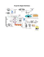
2 Process flow diagram examples The process flow diagram below depicts a single chemical engineering unit process known as an amine treating plant:
2.1 Multiple process units within an industrial plant
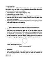
Some typical elements from process flow diagrams, as provided by the open source program, Dia. Click for image legend.
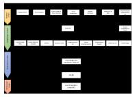
The process flow diagram below is an example of a Typically, process flow diagrams of a single unit process schematic or block flow diagram and depicts the various unit processes within a typical oil refinery: will include the following: • Process piping
3 Other items of interest
• Major equipment items • Control valves and other major valves
A PFD can be computer generated from process simulators (see List of Chemical Process Simulators), CAD packages, or flow chart software using a library of chemical engineering symbols. Rules and symbols are available
• Connections with other systems • Major bypass and recirculation streams 1
2
7
EXTERNAL LINKS
4 Standards • ISO 10628: Flow Diagrams For Process Plants General Rules • ANSI Y32.11: Graphical Symbols For Process Flow Diagrams (withdrawn 2003) • SAA AS 1109: Graphical Symbols For Process Flow Diagrams For The Food Industry
5 See also • Hazop Flow diagram of a typical amine treating process used in industrial plants
• Piping and instrumentation diagram (P&ID)
6 Further reading • Raymond E. Kirk and Donald F. Othmer (2001). Kirk-Othmer Encyclopedia of Chemical Technology (4th ed.). Wiley-Interscience. ISBN 0471419613. • M.S. Ray and M.G. Sneesby (1998). Chemical Engineering Design Project: A Case Study Approach (2nd ed.). Gordan and Breach Science Publishers. ISBN 9056991361. • R. Turton, R.C. Bailie, W.B. Whiting and J.S. Shaeiwitz (2002). Analysis, Synthesis, and Design of Chemical Processes (2nd ed.). Prentice Hall. ISBN 0-13-064792-6. • Fritz Ullmann (2002). Ullman’s Encyclopedia of Industrial Chemistry (6th ed.). Wiley-VCH. ISBN 3527-30385-5. • Srikumar Koyikkal (2013). Chemical Process Technology and Simulation (1st ed.). Prentice Hall India. ISBN 978-81-203-4709-0.
7 External links A typical oil refinery-SL
• Process Flow Sheet • The PFD at The Engineering Tool Box
from standardization organizations such as DIN, ISO or ANSI. Often PFDs are produced on large sheets of paper. PFDs of many commercial processes can be found in the literature, specifically in encyclopedias of chemical technology, although some might be outdated. To find recent ones, patent databases such as those available from the United States Patent and Trademark Office can be useful.
• Simplified process flowsheets and flow diagrams of process industries. Development of new integration methods and model flow diagrams.
3
8
Text and image sources, contributors, and licenses
8.1
Text
• Process flow diagram Source: https://en.wikipedia.org/wiki/Process_flow_diagram?oldid=711334177 Contributors: Jdpipe, Andreas Kaufmann, Mdd, Norro, BD2412, Dirkbike, Leeannedy, SmackBot, Chris the speller, Andrew c, Mbeychok, RHB, Atlien, Dgw, Gproud, RichardVeryard, Emitozzi, Thermbal, Bhanks, Hermann Luyken, Blood Oath Bot, Bitjungle, Eubulides, Jojalozzo, Addbot, MrOllie, חובבשירה, TaBOT-zerem, Legobot II, KamikazeBot, Rubinbot, Daniele Pugliesi, Materialscientist, Citation bot, Coretheapple, Rickproser, Con-struct, FrescoBot, Mean as custard, ZéroBot, CocuBot, Madeupwithit, MerlIwBot, BG19bot, Ele boz, BattyBot, Dirk Kossmann, Michipedian, YiFeiBot, Enggyd, Mela widiawati, Miriam-Mueller and Anonymous: 39
8.2
Images
• File:AmineTreating.png Source: https://upload.wikimedia.org/wikipedia/commons/f/f9/AmineTreating.png License: CC-BY-SA-3.0 Contributors: No machine-readable source provided. Own work assumed (based on copyright claims). Original artist: No machine-readable author provided. Mbeychok assumed (based on copyright claims). • File:Commons-logo.svg Source: https://upload.wikimedia.org/wikipedia/en/4/4a/Commons-logo.svg License: CC-BY-SA-3.0 Contributors: ? Original artist: ? • File:Pfd-symbols.png Source: https://upload.wikimedia.org/wikipedia/commons/c/c0/Pfd-symbols.png License: GPL Contributors: http://en.wikipedia.org/wiki/File:Pfd-symbols.png Original artist: en:User:Jdpipe • File:RefineryFlow.png Source: https://upload.wikimedia.org/wikipedia/commons/6/60/RefineryFlow.png License: CC-BY-SA-3.0 Contributors: ? Original artist: ?
8.3
Content license
• Creative Commons Attribution-Share Alike 3.0