![Quantum Q Vision [PDF]](https://pdfs.asia/img/200x200/quantum-q-vision.jpg)
15 0 5 MB
Q-VISION HF Series™ X-ray Generators Operator’s Manual
Manual Part No. DC30-101 Revision B
This manual is copyrighted and all rights are reserved. No portion of this document may be copied, photocopied, reproduced, translated, or reduced to any electronic medium or machine readable form without prior consent in writing from Quantum Medical Imaging, LLC. (QMI)
Copyright© 2010 QMI
Quantum Medical Imaging, LLC 2002-B Orville Drive North Ronkonkoma, NY 11779-7661 USA Phone: (631) 567-5800 Fax: (631) 567-5074 E-mail: [email protected] www.quantummedical.net
Made in U.S.A.
Revision History
REVISION
DATE
TYPE OF MODIFICATION
A
2/5/10
Initial Release
B
5/28/10
Update for CE
Page Number
Rev
i - iv
B
1-1 to 1-14
B
2-1 to 2-20
B
3-1 to 3-38
B
4-1 to 4-24
B
5-1 to 5-8
B
6-1 to 6-6
B
Page Number
HF Series X-ray Generators - Operator’s Manual Quantum Medical Imaging, LLC
Rev
Page Number
Rev
Revision B
i
Revision History
THIS PAGE INTENTIONALLY LEFT BLANK
Revision B
ii
HF Series X-ray Generators - Operator’s Manual Quantum Medical Imaging, LLC
Table of Contents
CHAPTER 1 - SAFETY NOTICES GENERAL SAFETY INFORMATION ......................................................... 1-3 WARNINGS, CAUTIONS, NOTES ........................................................... 1-3 REGULATORY COMPLIANCE ................................................................. 1-5 CLASSIFICATION ........................................................................... 1-5 INTENDED USE ............................................................................. 1-6 COMPATIBILITY ............................................................................ 1-6 INTENDED OPERATOR ................................................................... 1-6 TRAINING ..................................................................................... 1-6 ACCOMPANYING DOCUMENTATION ................................................ 1-6 APPLICABLE STANDARDS ............................................................... 1-7 DISPOSAL OF BATTERIES AND ACCUMULATORS (DIRECTIVE 2006/66/EC) .............................................................. 1-8 ELECTROMAGNETIC COMPATIBILITY (EN 60601-1-2:2007/IEC 60601-1-2:2007) ........................................... 1-8 ABBREVIATION DEFINITION .............................................................. 1-14
CHAPTER 2 - GENERAL INFORMATION OVERVIEW .......................................................................................... 2-3 INTENDED USE ............................................................................. 2-4 KEY FEATURES .............................................................................. 2-4 PERFORMANCE SPECIFICATIONS ......................................................... 2-5 ELECTRIC OUTPUT DATA ............................................................... 2-9 MAIN COMPONENTS .......................................................................... 2-12 ACCESSORIES ................................................................................... 2-13 CONTROLS AND INDICATORS ............................................................ 2-13 HELP SERVICES SCREEN .................................................................... 2-19
CHAPTER 3 - OPERATION OVERVIEW .......................................................................................... 3-3 POWER ON/OFF PROCEDURES ....................................................... 3-3 Power On Procedure ................................................................ 3-3 Power Off Procedure ................................................................ 3-4 Automatic Power Standby Mode ................................................ 3-5 DAILY TUBE WARM-UP PROCEDURE ............................................... 3-6 SETTING UP TO TAKE EXPOSURES ....................................................... 3-7 RECEPTOR SELECTION .................................................................. 3-7 MODE SELECTION ......................................................................... 3-9 Manual Mode ......................................................................... 3-11 AEC Mode ............................................................................. 3-12 APR Mode ............................................................................. 3-18 TAKING AN EXPOSURE ................................................................ 3-24
HF Series X-ray Generators - Operator’s Manual Quantum Medical Imaging, LLC
Revision B
iii
Table of Contents
Exposures ..............................................................................3-25 Instantaneous Exposures ........................................................3-25 HEAT UNIT COMPUTER ................................................................3-25 FAULT MESSAGES ........................................................................3-26 HELP SCREEN FEATURES ....................................................................3-31
CHAPTER 4 - APR EDITOR OVERVIEW ......................................................................................... 4-3 ACCESSING THE APR EDIT MODE .................................................. 4-3 APR EDIT MODE ............................................................................ 4-6 Editing a View Name ................................................................ 4-6 Editing Programmable Exposure Settings ..................................4-10 Making a Back Up Copy of the APR Program File .......................4-20 Restoring APR Program from Back Up Copy ..............................4-21
CHAPTER 5 - USER MAINTENANCE OVERVIEW ......................................................................................... 5-3 USER MAINTENANCE ..................................................................... 5-3 SYSTEM SETTINGS ........................................................................ 5-4 ACCESSING SERVICE MODE ..................................................... 5-4
CHAPTER 6 - WARRANTY INFORMATION WARRANTY STATEMENT ..................................................................... 6-3 WARRANTY EXCLUSIONS ..................................................................... 6-4 BUYER’S REMEDIES ............................................................................. 6-5 WARRANTY RETURN PROCEDURE ........................................................ 6-5 EQUIPMENT IN TRANSIT ..................................................................... 6-5 VOIDING WARRANTY .......................................................................... 6-6
Revision B
iv
HF Series X-ray Generators - Operator’s Manual Quantum Medical Imaging, LLC
Chapter
1
SAFETY NOTICES
1-1
1-2
Chapter 1 Safety Notices
GENERAL SAFETY INFORMATION Quantum products are designed to meet stringent safety standards. All medical electrical equipment requires proper installation, operation, and maintenance (particularly with regard to safety). It is vital that the user read, understand, note, and where applicable, strictly observe all Warnings, Cautions, Notes and Safety markings within this document and on the equipment, and that the user strictly follow all safety directions in this manual to help ensure the safety of users and patients. Every reasonable precaution has been taken during manufacture to safeguard the health and safety of persons who will operate this equipment. The following precautions must be observed at all times.
WARNINGS, CAUTIONS, NOTES The following samples show how warnings, cautions, and notes appear in this document. The text explains their intended use.
WARNING
Indicates injury or death is possible if the instructions are not obeyed. Instructs users to refer to documentation if displayed without warning text.
CAUTION
Indicates that damage to equipment is possible if the instructions are not obeyed.
NOTE
Notes provide advice and highlight unusual points. A note is not intended as an instruction.
The purpose of safety icons, such as those shown below, is to indicate at a glance the type of caution, warning or danger.
WARNING
Ionizing radiation: indicates the possibility of increased levels of radiation.
WARNING
Dangerous voltage: indicates the presence of high voltage.
WARNING
Warning, hot surface.
HF Series X-ray Generators - Operator’s Manual Quantum Medical Imaging, LLC
Revision B
1-3
Chapter 1 Safety Notices
WARNING Quantum Medical Imaging, LLC disclaims all responsibility from any injury resulting from improper application of this equipment. This equipment is sold to be used exclusively under the prescribed direction of a person who is licensed by law to operate equipment of this nature. This equipment must be used in accordance with all safety procedures described in this manual and must not be used for purposes other than those described herein. In the United States, Federal law restricts this device to sale, distribution, and use by or on order of a licensed physician. Quantum Medical Imaging, LLC cannot assume responsibility for any malfunctioning of this equipment resulting from improper operation, maintenance, or repair, or from damage or modification of its components. Failure to observe these warnings may cause serious injuries.
WARNING X-rays are hazardous to both patient and operator unless established safe exposure factors and operating instructions are observed. Only qualified and authorized personnel shall operate this system. In this context, qualified means those legally permitted to operate this equipment in the jurisdiction in which the equipment is being used, and authorized means those authorized by the authority controlling the use of the equipment. Full use must be made of all radiation protection features, devices, systems, procedures and accessories. It is important that everyone having anything to do with x-radiation be properly trained and fully acquainted with the recommendations of the National Council on Radiation Protection and Measurements as published in NCRP Reports available from NCRP Publications, 7910 Woodmont Avenue, Suite 800, Bethesda, Maryland 20814-3095 (www.ncrp.com), and of the International Commission on Radiological Protection (www.icrp.org), and take adequate steps to protect against injury.
WARNING X-ray equipment may cause injury if used improperly. The instructions contained in this manual must be read and followed when operating this unit. Personal radiation monitoring and protective devices are available. You are urged to use them to protect against unnecessary X-ray exposure.
Revision B
1-4
HF Series X-ray Generators - Operator’s Manual Quantum Medical Imaging, LLC
Chapter 1 Safety Notices
REGULATORY COMPLIANCE This certified Quantum Medical Imaging, LLC medical device has been designed, manufactured, and calibrated to comply with governing Federal Regulations 21 CFR Subchapter J and the performance standards attendant thereto. Upon installation, all certified products require the filing of Form FD-2579 "Report of Assembly of a Diagnostic X-ray System" by the assembler (i.e., the installer) with the appropriate agencies; the "Installation Quality Assurance Checklist" must also be completed and properly distributed upon installation. A copy of each form (pink copy) is provided to the user. The installation report is completed by the installer and returned to Quantum Medical Imaging, LLC. Those responsible for the planning of X-ray equipment installations must be thoroughly familiar and comply completely with NCRP Report No. 49, "Structural Shielding Design and Evaluation for Medical Use of X-rays and Gamma Rays of Energies up to 10 MeV", as revised or replaced in the future. Those authorized to operate, test, participate in or supervise the operation of the equipment must be thoroughly familiar and comply completely with the currently established safe exposure factors and procedures described in publications such as Subchapter J of Title 21 of the Code of Federal Regulations, "Diagnostic X-ray Systems and Their Major Components," and NCRP Report No. 102, “Medical X-ray, Electron Beam and Gamma Ray Protection for Energies Up to 50 MeV—Equipment Design and Use” as revised or replaced in the future. Q-VISION HF Series X-ray Generators must only be used in rooms that comply with all applicable laws or regulations that have the force of law, concerning electrical safety for this type of equipment. Scheduled maintenance is essential to the assurance of continued integrity of this equipment with respect to regulatory compliance. The continuance of certified performance to the regulatory standard is incumbent upon the user's diligent conformance to recommended maintenance instructions. Do not use this equipment until you are sure that the planned maintenance program is up to date. CLASSIFICATION This product has been classified as Class I by Underwriters Laboratories, Inc. Equipment not suitable for use in the presence of a flammable anesthetic mixture with air or with oxygen or with nitrous oxide. Protection against Harmful Ingress of Water (Ordinary), enclosed equipment without protection against ingress of liquids. MEDICAL ELECTRICAL EQUIPMENT WITH RESPECT TO ELECTRIC SHOCK, FIRE, MECHANICAL HAZARDS ONLY IN ACCORDANCE WITH UL 60601-1 AND CAN/CSA C22.2 NO. 601.1 98UA
HF Series X-ray Generators - Operator’s Manual Quantum Medical Imaging, LLC
Revision B
1-5
Chapter 1 Safety Notices
The following symbols may be used for marking on this equipment or equipment documentation: Earth (ground)
Dangerous Voltage
Protective Earth (ground)
Attention, consult accompanying documents
Power ON (part of equipment)
Power OFF (part of equipment)
Stand By
Non-ionizing radiation
Ionizing radiation
Alternating current
COMPATIBILITY The equipment described in this manual must only be used in combination with other equipment or components if these are expressly recognized by Quantum Medical Imaging, LLC as compatible. INTENDED OPERATOR The Q-VISION HF Series X-ray Generator is intended to be installed, used and operated only in accordance with the safety procedures given within this manual for the purpose for which it was designed. Before attempting to work with this equipment, read, understand, note and strictly observe all warnings, cautions and safety markings on the equipment. Users include those persons who actually handle the equipment and those who have authority over the equipment. TRAINING Users of Q-VISION HF Series X-ray Generator shall have received adequate training on its safe and effective use before attempting to work with the equipment. Training requirements may vary from country to country. The User shall make sure that training is received in accordance with local laws or regulations that have the force of law.
Revision B
1-6
HF Series X-ray Generators - Operator’s Manual Quantum Medical Imaging, LLC
Chapter 1 Safety Notices
ACCOMPANYING DOCUMENTATION The documentation consists of a User manual (this document) and related documentation: •
Service Manual P/N DC30-011: Contains technical and service documentation for this product, including installation and configuration instructions to be performed by qualified persons
The documentation shall be kept with the system for easy reference. APPLICABLE STANDARDS Q-VISION HF Series X-ray Generators comply with the following regulatory standards: •
FDA Center for Devices and Radiological Health (CDRH) - Title 21 CFR Subchapter J
• •
EN 60601-1: 1990 + A1:1993 + A2:1995 + A13:1996
•
IEC 60601-2-7: 1998(E)
•
CAN/CSA-C22.2 No. 601.1-M90, 2005 (Medical Electrical Equipment, part 1: General Requirements for Safety)
•
UL 60601-1, 1st Edition, 2006-04-26 (Medical Electrical Equipment, part 1: General Requirements for Safety)
•
IEC 60601-1 Medical electrical equipment, Part 1: General requirements for safety
•
IEC 60601-1-2: 2007
•
EC Directive 93/42/EEC for Medical Devices
EU Authorized Representative: Medizintechnik Berlin GmbH Altentreptower, Strasse 59 12683 Berlin - Germany Phone: +49-302-82 4726 Fax: +49-302-82 6382 E-mail: [email protected]
HF Series X-ray Generators - Operator’s Manual Quantum Medical Imaging, LLC
Revision B
1-7
Chapter 1 Safety Notices
DISPOSAL OF BATTERIES AND ACCUMULATORS (DIRECTIVE 2006/66/EC) In accordance with the European Directive 2006/66/EC, batteries and accumulators are labeled to indicate that they are to be collected separately and recycled at end of life. The label on the battery may also include a chemical symbol for the metal concerned in the battery (Pb for lead, Hg for mercury and Cd for cadmium). Users of batteries and accumulators must not dispose of batteries and accumulators as unsorted municipal waste, but use the collection framework available to customers for the return, recycling, and treatment of batteries and accumulators. Participation is important to minimize any potential effects of batteries and accumulators on the environment and human health due to the potential presence of hazardous substances.
ELECTROMAGNETIC COMPATIBILITY (EN 60601-1-2:2007/IEC 606011-2:2007) Q-VISION HF Series X-ray Generators are intended for use in the electromagnetic environment specified below. As such, the generator must be installed and put into service according to the information provided in the accompanying Service Manual. The Q-VISION HF Series X-ray Generator complies with the requirements of applicable EMC standards. Portable and mobile RF communications equipment can affect medical electrical equipment. It is therefore recommended that the operation of equipment of this type, such as mobile telephones, cordless microphones and other similar mobile radio equipment, be restricted from the vicinity of this device. Use of accessories, transducers and cables, other than those specified in the accompanying documents, may result in increased emissions or decreased immunity of the equipment. Guidance and manufacturer's declaration - electromagnetic emissions
The HF Series X-ray Generator is intended for use in the electromagnetic environment specified below. The customer or the user of the HF Series X-ray Generator should assure that it is used in such an environment. Emissions test RF emissions CISPR 11
Revision B
1-8
Compliance Group 1
Electromagnetic environment guidance The HF Series X-ray Generator uses RF energy only for their internal functions. Therefore, the RF emissions are very low and are not likely to cause any interference in nearby electronic equipment.
HF Series X-ray Generators - Operator’s Manual Quantum Medical Imaging, LLC
Chapter 1 Safety Notices
Guidance and manufacturer's declaration - electromagnetic emissions RF emissions CISPR 11
Class A
Harmonic emissions IEC 61000-3-2
Class A
Voltage fluctuations/ flicker emissions IEC 61000-3-3
Complies
HF Series X-ray Generators - Operator’s Manual Quantum Medical Imaging, LLC
The HF Series X-ray Generator is suitable for use in all establishments other than domestic and those directly connected to the public lowvoltage power supply network that supplies buildings used for domestic purposes.
Revision B
1-9
Chapter 1 Safety Notices
Guidance and manufacturer's declaration - electromagnetic immunity
The HF Series X-ray Generator is intended for use in the electromagnetic environment specified below. The customer or the user of the HF Series X-ray Generator should assure that it is used in such an environment. Immunity test
IEC 60601 test level
Compliance level
Electromagnetic environment - guidance
Electrostatic discharge (ESD) IEC 61000-4-2
±6 kV contact ±8 kV air
±6 kV contact ±8 kV air
Floors should be wood, concrete or ceramic tile. If floors are covered with synthetic material, the relative humidity should be at least 30%.
Electrical fast transient/burst IEC 61000-4-4
±2 kV for power supply lines ±1 kV for input/output lines
±2 kV for power supply lines ±1 kV for input/output lines
Mains power quality should be that of a typical commercial or hospital environment.
Surge IEC 61000-4-5
±1 kV differential mode ±2 kV common mode
±1 kV differential mode ±2 kV common mode
Mains power quality should be that of a typical commercial or hospital environment.
Voltage dips, short interruption, and voltage variations on power supply input lines IEC 60601-4-11
< 5% UT (>95% dip in UT) for 0.5 cycle
< 5% UT (>95% dip in UT) for 0.5 cycle
40% UT (60% dip in UT) for 5 cycles
40% UT (60% dip in UT) for 5 cycles
70% UT (30% dip in UT) < 5% UT (> 95% dip in UT) for 5 s
70% UT (30% dip in UT) < 5% UT (> 95% dip in UT) for 5 s
Mains power quality should be that of a typical commercial or hospital environment. If the user of the HF Series X-ray Generator requires continued operation during power mains interruptions, it is recommended that the HF Series X-ray Generator be powered from an uninterruptible power supply or battery.
3 A/m
3 A/m
Power frequency (50/60 Hz) IEC 61000-4-8
Power frequency magnetic fields should be at levels characteristic of a typical location in a typical commercial or hospital environment
NOTE: UT is the A.C. mains voltage prior to application of the test level.
Revision B
1-10
HF Series X-ray Generators - Operator’s Manual Quantum Medical Imaging, LLC
Chapter 1 Safety Notices
Guidance and manufacturer's declaration - electromagnetic immunity
The HF Series X-ray Generator is intended for use in the electromagnetic environment specified below. The customer or the user of the HF Series of X-ray generators (including TechVision option) should assure that it is used in such an environment. Immunity test
IEC 60601 test level
Compliance level
Electromagnetic environment - guidance Portable and mobile RF communications equipment should be used no closer to any part of the HF Series X-ray Generator, including cables, than the recommended separation distance calculated from the equation applicable to the frequency of the transmitter. Recommended separation distance
Conducted RF IEC 61000-4-6
3 Vrms 150 kHz to 80MHz
3 Vrms
Radiated RF IEC 61000-4-3
3 V/m 80 MHz to 2,5 GHz
3 V/m
d 1,2 P d 1,2 P
, 80 MHz to 800 MHz
d 2,3 P
, 800 MHz to 2,5 GHz
where P is the maximum output power rating of the transmitter in watts (W) according to the transmitter manufacturer and d is the recommended separation distance in metres (m). Field strengths from fixed RF transmitters, as determined by an electromagnetic site surveya, should be less than the compliance level in each frequency range.b Interference may occur in the vicinity of equipment marked with the following symbol:
HF Series X-ray Generators - Operator’s Manual Quantum Medical Imaging, LLC
Revision B
1-11
Chapter 1 Safety Notices
Guidance and manufacturer's declaration - electromagnetic immunity NOTE 1 At 80 MHz and 800 MHz, the higher frequency range applies. NOTE 2 These guidelines may not apply in all situations. Electromagnetic propagation is affected by absorption and reflection from structures, objects and people. a
Field strengths from fixed transmitters, such as base stations for radio (cellular/cordless) telephones and land mobile radios, amateur radio, AM and FM radio broadcast and TV broadcast cannot be predicted theoretically with accuracy. To assess the electromagnetic environment due to fixed RF transmitters, an electromagnetic site survey should be considered. If the measured field strength in the location in which the HF Series X-ray Generator is used exceeds the applicable RF compliance level above, the HF Series of X-ray generators (including TechVision option) should be observed to verify normal operation. If abnormal performance is observed, additional measures may be necessary, such as re-orienting or relocating the HF Series X-ray Generator. b Over the frequency range 150 kHz to 80 kHz, field strengths should be less than 3 V/m.
Revision B
1-12
HF Series X-ray Generators - Operator’s Manual Quantum Medical Imaging, LLC
Chapter 1 Safety Notices
Recommended separation distances between portable and mobile RF communications equipment and the HF Series of X-ray generators (including TechVision option)
The HF Series X-ray Generator is intended for use in an electromagnetic environment in which radiated RF disturbances are controlled. The customer or the user of the HF Series X-ray Generator can help prevent electromagnetic interference by maintaining a minimum distance between portable and mobile RF communications equipment (transmitters) and the HF Series X-ray Generator as recommended below, according to the maximum output power of the communications equipment. Rated maximum output power of transmitter W
Separation distance according to frequency of transmitter m 150 kHz to 80 MHz
d 1,2 P
80 MHz to 800 MHz
d 1,2 P
800 MHz to 2,5 GHz
d 2,3 P
0,01
0,12
0,12
0,23
0,1
0,38
0,38
0,73
1
1,2
1,2
2,3
10
3,8
3,8
7,3
100
12
12
23
For transmitters rated at a maximum output power not listed above, the recommended separation distance d in metres (m) can be estimated using the equation applicable to the frequency of the transmitter, where P is the maximum output power rating of the transmitter in watts (W) according to the transmitter manufacturer. NOTE 1: At 80 MHz and 800 MHz, the separation distance for the higher frequency range applies. NOTE 2: These guidelines may not apply in all situations. Electromagnetic propagation is affected by absorption and reflection from structures, objects and people.
HF Series X-ray Generators - Operator’s Manual Quantum Medical Imaging, LLC
Revision B
1-13
Chapter 1 Safety Notices
ABBREVIATION DEFINITION The following abbreviations and acronyms may be found in this document. Their definition is explained below. ADC
Analog-to-digital converter
AEC
Automatic Exposure Control
APR
Anatomical Programmed Region
cm
Centimeters (thickness)
HF
High Frequency
HSS
High-speed starter
kVp
Tube voltage (kilovolts peak)
LCD
Liquid crystal display
mA
Tube current (milliampere)
mAs
Time-current product
OCP
Operator Control Panel
SE
Stored Energy
sec
Expose on time (seconds)
Revision B
1-14
HF Series X-ray Generators - Operator’s Manual Quantum Medical Imaging, LLC
Chapter
2
GENERAL INFORMATION
2-1
2-2
Chapter 2 General Information
OVERVIEW NOTE: The user should read this manual in its entirety prior to using this equipment. It should be kept in a location near the equipment and be readily accessible to those who operate it. This document is intended to assist users in the safe and effective operation of the equipment described herein. Pay special attention to all the information described in the Safety section (refer to Chapter 1, SAFETY NOTICES). This manual is written for trained users of the Q-VISION High-Frequency (HF) Series X-ray Generator, hereinafter referred to as the HF Series X-ray Generator, and for authorized field service personnel. Quantum Medical Imaging, LLC assumes no liability for use of this document if any unauthorized changes to the content or format have been made. The HF Series X-ray Generator, includes the following models: •
Model QGV-32: 32 kW, 208 - 260 VAC single-phase input configuration
•
Model QGV-32-SE: 32 kW, "STORED ENERGY" 115/230 VAC single-phase input configuration
• • •
Model QGV-32-2: 32 kW, 208 - 240 VAC three-phase input configuration Model QGV-32-3: 32 kW, 380 - 480 VAC three-phase input configuration QGV-32-5: 32 kW, 380 - 480 VAC single-phase input configurationModel QGV-40: 40 kW, 208 - 260 VAC single-phase input configuration
•
Model QGV-40-SE: 40 kW, "STORED ENERGY" 115/230 VAC single-phase input configuration
• • •
Model QGV-40-2: 40 kW, 208 - 240 VAC three-phase input configuration Model QGV-40-3: 40 kW, 380 - 480 VAC three-phase input configuration QGV-40-5: 40 kW, 380 - 480 VAC single-phase input configurationModel QGV-50-SE: 50 kW, "STORED ENERGY" 115/230 VAC single-phase input configuration Model QGV-50: 50 kW, 380 - 480 VAC three-phase input configuration
•
HF Series X-ray Generators - Operator’s Manual Quantum Medical Imaging, LLC
Revision B
2-3
Chapter 2 General Information
• • •
Model QGV-50-2: 50 kW, 208 - 240 VAC three-phase input configuration Model QGV-65: 65 kW, 380 - 480 VAC three-phase input configuration Model QGV-80: 80 kW, 380 - 480 VAC three-phase input configuration
This product is intended to be used and operated only in accordance with the safety procedures given within this manual for the purpose for which it was designed. The intended use is given below. Nothing stated in this manual reduces user's professional responsibilities for sound judgment and best practice. INTENDED USE The HF Series X-ray Generator is a diagnostic X-ray high-voltage generator. It is intended to supply and control the electrical energy applied to a diagnostic X-ray tube for medical/veterinary radiographic examinations. Use of the equipment for purposes other than those intended and expressly stated by the manufacturer, as well as incorrect use or operation, may relieve the manufacturer or his agent from all or some of the responsibility for resultant noncompliance, damage or injury. KEY FEATURES It is imperative that all safety procedures described in this manual be strictly adhered to in order to ensure the safety of both patient and user. The significant physical and performance characteristics of the HF Series X-ray Generators are as follows: • • • • • • •
Revision B
2-4
Ultra high-frequency (up to 120 kHz) voltage waveform for highly efficient X-ray production Manual, AEC (optional), and automatic (APR) modes of operation Anatomic Programmability (APR) - pre-defined and customized technique selection Wall/table/none image receptor selection Multi-language display capability Optional pedestal/wall mount control console Compact generator cabinet design
HF Series X-ray Generators - Operator’s Manual Quantum Medical Imaging, LLC
Chapter 2 General Information
PERFORMANCE SPECIFICATIONS Refer to Table 2-1 for performance specifications of single-phase (non-stored energy) HF Series X-ray Generators. Table 2-1. HF Series Single-Phase Generator Performance Specifications
N/A
Models QG-32, QG-32-5
Models QG-40, QG-40-5
(Catalog No. QGV-32)
(Catalog No. QGV-40)
Maximum kW
N/A
32
40
mA Stations; Small Focus (S) Large Focus (L)
N/A
25S, 75S, 150S 100L, 200L, 250L, 320L, 400L, 500L
25S, 75S, 150S 100L, 200L, 250L, 320L, 400L, 500L
mA Accuracy
N/A
5% +1mA
5% +1mA
kVp Range (kVp)
N/A
40-125
40-125
kVp increments (kVp/ step)
N/A
1.0
1.0
kV Accuracy
N/A
4%
4%
150 kVp optional
N/A
Yes
Yes
Time Range (sec.)
N/A
0.001 - 6.3
0.001 - 6.3
Time Accuracy*
N/A
1 mS +0.5%*
1 mS +0.5%*
Minimum Exposure Time (seconds)
N/A
0.001
0.001
mAs Range**
N/A
0.025-600
0.025-600
High-SpeedStarter
N/A
No
No
Ripple Voltage (output)
N/A
5%
5%
* Time measured at 75% of the peak kVp waveform; For exposure times from 1.0 mS to 49 mS, time accuracy is 2% + 1 mS; for exposure times from 50 mS to 100 mS, time accuracy is 1% + 1 mS NOTE: AEC TECHNIQUES SHOULD HAVE EXPOSURE TIMES EXCEEDING 8 MILLISECONDS.
** mAs is tube dependent; the generator may not reach maximum mAs due to tube type.
HF Series X-ray Generators - Operator’s Manual Quantum Medical Imaging, LLC
Revision B
2-5
Chapter 2 General Information
Refer to Table 2-2 for performance specifications of single-phase stored energy (SE) HF Series X-ray Generators. Table 2-2. HF Series Single-Phase Stored Energy Generator Performance Specifications
Model QG-32-SE
Model QG-40-SE
Model QG-50-SE
(Catalog No. QGV-32-SE)
(Catalog No. QGV-40-SE)
(Catalog No. QGV-50-SE)
N/A
32
40
50
mA Stations; Small Focus (S) Large Focus (L)
N/A
25S, 50S, 75S, 150S 100L, 160L, 200L, 250L, 320L, 400L
25S, 50S, 75S, 150S 100L, 200L, 250L, 320L, 400L, 500L
25S, 50S, 75S, 150S 100L, 200L, 250L, 320L, 400L, 500L, 600L
mA Accuracy
N/A
5% +1mA
5% +1mA
5% +1mA
kVp Range (kVp)
N/A
40-125
40-125
40-125
kVp increments (kVp/ step)
N/A
1.0
1.0
1.0
kV Accuracy
N/A
4%
4%
4%
150 kVp optional?
N/A
No
No
No
Time Range (sec.)
N/A
3
3
3
Time Accuracy*
N/A
1 mS +0.5%*
1 mS +0.5%*
1 mS +0.5%*
Minimum Exposure Time (seconds)
N/A
0.001
0.001
0.001
mAs Range**
N/A
0.025-400
0.025-400
0.025-400
High-Speed Starter
N/A
No
No
No
Ripple Voltage (output)
N/A
5%
5%
5%
Maximum kW
*
Maximum exposure time is a function of kV and mAs settings and the age of the batteries; Time measured at 75% of the peak kVp waveform. For exposure times from 1.0 mS to 49 mS, time accuracy is 2% + 1 mS; for exposure times from 50 mS to 100 mS, time accuracy is 1% + 1 mS NOTE: AEC TECHNIQUES SHOULD HAVE EXPOSURE TIMES EXCEEDING 8 MILLISECONDS.
**
mAs is tube dependent; the generator may not reach maximum mAs due to tube type.
Revision B
2-6
HF Series X-ray Generators - Operator’s Manual Quantum Medical Imaging, LLC
Chapter 2 General Information
Refer to Table 2-3 for performance specifications of three-phase HF Series X-ray Generators. Table 2-3. HF Series Three-Phase Generator Performance Specifications
Maximum kW mA Stations; Small Focus (S) Large Focus (L)
mA Accuracy kVp Range (kVp)
Model QG-32-2, QG-32-3
Model QG-40-2, QG-40-3
Model QG-50, QG-50-2
Model QG-65
Model G-80
Cat. No. QGV-32-2, QGV-32-3
Cat. No. QGV-40-2 QGV-40-3
Cat. No. QGV-50 QGV-50-2
Cat. No. QGV-65
Cat. No. QGV-80
32
40
50
65
25S, 75S, 150S 100L, 200L, 250L, 320L, 400L, 500L
25S, 75S, 150S 100L, 200L, 250L, 320L, 400L, 500L
25S, 75S, 150S 100L, 200L, 320L, 400L, 500L, 650L
25S, 75S, 150S 100L, 200L, 320L, 400L, 500L, 650L, 800
5% +1mA
5% +1mA 40-125 (40-150 with QG-150 option)
5% +1mA 40-125 (40-150 with QG-150 option)
5% +1mA
80 25S, 75S, 150S 100L, 200L, 320L, 400L, 500L, 650L, 800 5% +1mA
40-150
40-150
1.0
1.0
1.0
1.0
1.0
4%
4%
4%
4%
4%
Yes
Yes
Yes
Standard
Standard
0.001 - 6.3
0.001 - 6.3
0.001 - 6.
0.001 - 6.3
0.001 - 6.3
1 mS +0.5%*
1 mS +0.5%*
1 mS +0.5%*
1 mS +0.5%*
1 mS +0.5%*
0.001
0.001
0.001
0.001
0.001
0.025-600
0.025-600
0.025-800
0.025-800
0.025-800
No
Option
Option
Yes
Yes
5%
5%
5%
5%
5%
40-125
kVp increments (kVp/step) kV Accuracy 150 kVp optional? Time Range (sec.) Time Accuracy* Minimum Exposure Time (sec.) mAs Range** High-Speed Starter*** Ripple Voltage (output)
*
Time measured at 75% of the peak kVp waveform; For exposure times from 1.0 mS to 49 mS, time accuracy is 2% + 1 mS; for exposure times from 50 mS to 100 mS, time accuracy is 1% + 1 mS
HF Series X-ray Generators - Operator’s Manual Quantum Medical Imaging, LLC
Revision B
2-7
Chapter 2 General Information
**
NOTE: AEC TECHNIQUES SHOULD HAVE EXPOSURE TIMES EXCEEDING 8 MS. mAs is tube dependent; the generator may not reach maximum mAs due to tube type. In AEC mode, the mAs is limited to 600.
*** High-Speed Starter Duty Cycle: are not to exceed two activations within any one minute period
Revision B
2-8
HF Series X-ray Generators - Operator’s Manual Quantum Medical Imaging, LLC
Chapter 2 General Information
ELECTRIC OUTPUT DATA Table 2-4. Electric Output Data OUTPUT PARAMETER Nominal X-ray tube voltage and highest X-ray tube current obtainable at that voltage
Maximum X-ray tube current and highest X-ray tube voltage obtainable at that current
MODEL (CAT. NO.)
LOADING FACTOR
N/A
N/A
QG-32, QG-32-2, QG-32-3, QG-32-5 (QGV-32, QGV-32-2, QGV-32-3, QGV-32-5)
125 kV, 250 mA (150 kV, 200 mA with QG-150 option)
QG-40, QG-40-2, QG-40-3, QG-40-5 (QGV-40, QGV-40-2, QGV-40-3, QGV-40-5)
125 kV, 320 mA (150 kV, 250 mA with QG-150 option)
N/A
N/A
QG-32-SE (QGV-32-SE)
125 kV, 250 mA
QG-40-SE (QGV-40-SE)
125 kV, 320 mA
QG-50, QG-50-2 (QGV-50, QGV-50-2)
125 kV, 400 mA (150 kV, 320 mA with QG-150 option)
QG-50-SE (QGV-50-SE)
125 kV, 400 mA
QG-65 (QGV-65)
150 kV, 800 mA
QG-80 (QGV-80)
150 kV, 800 mA
N/A
N/A
QG-32, QG-32-2, QG-32-3, QG-32-5 (QGV-32, QGV-32-2, QGV-32-3, QGV-32-5)
500 mA, 64 kV
QG-40, QG-40-2, QG-40-3, QG-40-5 (QGV-40, QGV-40-2, QGV-40-3, QG-40-5)
500 mA, 80 kV
N/A
N/A
QG-32-SE (QGV-32-SE)
400 mA, 80 kV
QG-40-SE (QGV-40-SE)
500 mA, 80 kV
QG-50, QG-50-2 (QGV-50, QGV-50-2)
650 mA, 76 kV
QG-50-SE (QGV-50-SE)
600 mA, 83 kV
QG-65 (QGV-65)
800 mA, 81 kV
QG-80 (QGV-80)
800 mA, 100 kV
HF Series X-ray Generators - Operator’s Manual Quantum Medical Imaging, LLC
Revision B
2-9
Chapter 2 General Information
Table 2-4. Electric Output Data OUTPUT PARAMETER Combination of X-ray tube current and X-ray tube voltage resulting in highest output power (Note: All mA stations below those listed
Revision B
2-10
MODEL (CAT. NO.)
LOADING FACTOR
N/A
N/A
QG-32, QG-32-2, QG-32-3, QG-32-5 (QGV-32, QGV-32-2, QGV-32-3, QGV-32-5)
320 mA, 100 kV 400 mA, 80 kV 500 mA, 64 kV
QG-40, QG-40-2, QG-40-3, QG-40-5 (QGV-40, QGV-40-2, QGV-40-3, QGV-40-5)
400 mA, 100 kV 500 mA, 80 kV
N/A
N/A
QG-32-SE (QGV-32-SE)
320 mA, 100 kV 400 mA, 80 kV
QG-40-SE (QGV-40-SE)
320 mA, 125 kV 400 mA, 100 kV 500 mA, 83 kV
QG-50, QG-50-2 (QGV-50, QGV-50-2)
400 mA, 125 kV 500 mA, 100 kV 650 mA, 76 kV
QG-50-SE (QGV-50-SE)
400 mA, 125 kV 500 mA, 100 kV 600 mA, 83 kV
QG-65 (QGV-65)
500 mA, 130 kV 650 mA, 123 kV 800 mA, 81 kV
QG-80 (QGV-80)
650 mA, 123 kV 800 mA, 100 kV
HF Series X-ray Generators - Operator’s Manual Quantum Medical Imaging, LLC
Chapter 2 General Information
Table 2-4. Electric Output Data OUTPUT PARAMETER Highest constant output power at 100 kV, 0.1 second (s)
MODEL (CAT. NO.)
LOADING FACTOR
N/A
N/A
QG-32, QG-32-2, QG-32-3, QG-32-5 (QGV-32, QGV-32-2, QGV-32-3, QGV-32-5)
32 kW (320 mA, 100 kV, 0.1 s)
QG-40, QG-40-2, QG-40-3, QG-40-5 (QGV-40, QGV-40-2, QGV-40-3, QGV-40-5)
40 kW (400 mA, 100 kV, 0.1 s)
N/A
N/A
QG-32-SE (QGV-32-SE)
32 kW (320 mA, 100 kV, 0.1 s)
QG-40-SE (QGV-40-SE)
40 kW (400 mA, 100 kV, 0.1 s)
QG-50, QG-50-2 (QGV-50, QGV-50-2)
50 kW (500 mA, 100 kV, 0.1 s)
QG-50-SE (QGV-50-SE)
50 kW (500 mA, 100 kV, 0.1 s)
QG-65 (QGV-65)
65 kW (650 mA, 100 kV, 0.1 s)
QG-80 (QGV-80)
80 kW (800 mA, 100 kV, 0.1 s)
Nominal shortest irradiation time (AEC exposures)
All models
0.008 second
Lowest mAs
All models
0.025 mAs (25 mA, 1.0 mS)
HF Series X-ray Generators - Operator’s Manual Quantum Medical Imaging, LLC
Revision B
2-11
Chapter 2 General Information
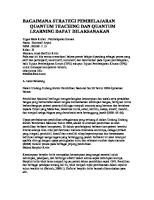
MAIN COMPONENTS See Figure 2-1. The HF Series X-ray Generator is comprised of: 1
Generator Cabinet - Contains the electronics for high voltage generation and control.
2
Touchscreen Operator Console - Contains the operator control panel, which has all generator operator controls and indicators; all aspects of X-ray techniques are entered at the operator control console. The operator console is a self-contained computer, running generator control software, designed for table top (picture frame-style) mounting (item 2). An optional wall-mount is available (QVG-WM). WARNING! The Touchscreen Operator Console complies with the UL 60950/EN 60950 standard for Information Technology. This means that, although it is absolutely safe, patients may not come into direct contact with the equipment. Therefore, the console must be placed outside a radius of 1.5 meters around the patient.
3
Power/Expose Control Box: Provides the operator with a means to control power to the Generator, and provides interface of the Expose switch to the X-ray imaging system.
Figure 2-1. HF Series X-ray Generator - Main Components
Revision B
2-12
HF Series X-ray Generators - Operator’s Manual Quantum Medical Imaging, LLC
Chapter 2 General Information
CONTROL PANEL COMPLIANCE LABEL (ON REAR OF TOUCH SCREEN COMPUTER, LOWER RIGHT CORNER)
GENERATOR REGULATORY MARKINGS LABEL (REFER TO CHAPTER 1 FOR MEANINGS OF SYMBOLS)
Model: QGV-80 Serial No.: QGV80-XXX-XXXX Manufactured: Month Year Manufactured by: Quantum Medical Imaging, LLC 2002 Orville Drive North Ronkonkoma, NY 11779 USA
GENERATOR SYSTEM LABEL X-RAY GENERATOR SYSTEM Model: QG-80 Serial No.: QG80-XXX-XXXX Manufactured by: Quantum Medical Imaging, LLC 2002 Orville Drive North Ronkonkoma, NY 11779 USA
GENERATOR CABINET LABEL Complies with FDA radiation performance standards set forth in CFR 21 Subchapter J applicable at date of manufacture
380-480
100
3 PHASE
Model: QG-80G Serial No.: QG80G-XXX-XXXX Manufactured: Month Year
MAX. MA MAX. KVP AMP MOM. AMPS L.T.
Q-VISION - GENERATOR-STBY-EXP BOX.cdr
800 150 200 (@440 VAC)