![Sole Plates [PDF]](https://pdfs.asia/img/200x200/sole-plates.jpg)
26 0 323 KB
CONVEYOR MANUFACTURERS ASSOCIATION OF SOUTH AFRICA NPC
TECHNICAL DOCUMENT CONVEYOR PULLEY BEARING SOLE PLATES CMA TD02 Rev00 2018
CONVEYOR PULLEY BEARING SOLE PLATES Most plummer blocks and bearings are robust and when properly sized, mounted and lubricated should render long and trouble-free life. Incorrect mounting or loading, poor lubrication and the use of improper or inappropriate tools can have a negative influence on the life of the installation. In the same way, the structures that support the pulleys and bearing assemblies should be designed to accommodate the forces that will be applied to the pulley. Being structural items, it is therefore necessary to insert fixed sole plates between the bearing housing and the steelwork supporting them. The correct selection of sole plates depends on the plummer block selection, the load induced by the conveyor belt and pulley and, to an extent, the structural support detail. Therefore, sole plates serve two basic purposes, namely to provide a flat surface for the bearing housing and to facilitate proper horizontal and vertical alignment of the pulleys. However, sole plates are not always required. For example, where the conveyors and pulleys are small, the sole plates may not be required, depending on the design of the support structure. In cases where the pulleys are large and heavy, they will require a higher degree of installation accuracy. Sole plates will allow the pulley assembly to be adjusted with minimal effort while ensuring the alignment of the pulley. The mounting tolerances and procedures for the bearing housings are of cardinal importance. It is recommended by most manufacturers that the surface for the bearing housing mounting should be finished to a roughness Ra 12,5 µm. The flatness of the surface should be to IT7 in accordance with ISO 1101:2012. For moderate loading, the flatness could be reduced to IT8, but the more stringent tolerance should be applied in the general case. The fixed sole plates are usually equipped with adjusting screws on each end, in order to facilitate the adjustment of the housing when the system is aligned. For conveyor pulley installations, the vertical and horizontal installation tolerances are fixed at 1:1000. Compared to the normal structural tolerance, which is often quoted as loosely as ±5 mm, the use of packs and adjusting screws becomes important when conveyor installations are considered. When shims or packs are required under the bearing housing, it is important that the shims or packs are made full length of the bearing housing base. Packing under the attachment bolts only will place an unnecessary stress on the unsupported centre portion of the housing. This will result in either the housing failing at the junction with the base, or distorting to such an extent that the bearing clearances will be affected. The result will be premature bearing failure or an increase in drag on the pulley, resulting in an increase in power consumption and accelerated wear of the pulley shell and lagging. Shims should be made of stainless sheet steel with sufficient strength and the ability to withstand corrosion from several media. Shims made from soft metals like Page 2 of 12
copper or brass typically compress over time, causing looseness, which can eventually lead to misalignment. Whenever possible, use only one shim and never stack more than three shims. The bolts attaching the plummer block should be specified as a minimum of grade 8.8 bolts with hexagon heads and hexagon nuts. The recommended tightening torque for the attachment bolts is given in the table below. The torque figures are quoted in N·m. Bolt M12 M16 M20 M24 M30
Torque 90 220 430 750 1400
It is to be noted that the torques quoted are based on the load passing vertically through the housing base. In the case when the resultant force does not act normal to the base, then it may be necessary to use grade 10.9 bolts and the tightening toque would be adjusted accordingly. A surface friction coefficient of about μ = 0,2 may be used to compute the required vertical force, based on the resultant force and the angle of the resultant with respect to the base. See Appendix A Where the bearing assemblies are to be mounted on stools, especially where the stools are designed with a sloping surface, then the sole plates should be mounted between the stool and the supporting structure. In this case, the bearings will be firmly bolted to the stools without soleplates. Sole plates are preferably shop-welded to the structure. Should the flatness of the soleplate be compromised by welding, alternative methods, such as bolting or adhesives may be specified. Sole plates may be bolted to the structure using countersunk screws and nuts, provided that the screws are capable of withstanding the shear forces arising from the load on the plummer blocks. The use of epoxy adhesives to allow the sole plates to be squared and seated in position may be considered. In this case, the effects of temperature changes on the adhesive bond between the sole plate and the structure must be considered. In addition, where the resultant force is not normal to the plane of the sole plate, the specification of the adhesive must be considered in conjunction with the adhesive supplier. Should an epoxy adhesive be considered, the maximum adhesive film thickness should be no more than 2,0 mm. Page 3 of 12
The supporting steel work is to have slots to match the sole plates, irrespective of the attachment method employed. The weld between the sole plate and the structure should make a water-tight seam on the first pass (±3 mm weld), so that stitch-welding (if applied) minimises weld distortion, which could affect the flatness of the plates. The corners of the sole plates may be cropped 45°×10 mm, in order to minimise snag points. Remove all snags and burrs from the edges by an appropriate method.
Page 4 of 12
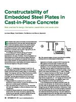
Sole plates may be divided into 4 basic types, as follows. a) b) c) d)
Type 1, for plummer blocks with two bolts Type 2 for plummer blocks with 4 bolts and single jacking bolts each side Type 3 for plummer blocks with 4 bolts and a double jacking block each side Type 4 for static-shafted pulley dead-eyes
For very large bearing housings, such as shafts equipped with BND housings with diameters in excess of 300 mm, the sole plates should be designed in consultation with the bearing housing supplier.
Page 5 of 12
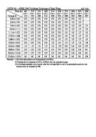
Type 1 Sole plates for 2-bolt bearings up to and including ø140 mm
=
C
D =
F
K
J
A B
E
E
G
H
= =
Drill & tap L for M long hexagonal head screw & nut
6 Dimensions
Mass kg
Shaft 40 50 65 75 90 100 110 115 125 135 140
A 170 210 230 260 320 350 350 380 420 450 470
B 275 330 355 395 460 490 490 525 590 620 640
C 345 400 425 465 550 580 580 615 680 710 730
D 65 75 85 100 120 130 130 140 160 170 170
E 30 40 40 40 50 50 50 50 50 50 50
F 30 40 40 40 50 50 50 50 50 50 50
G 8 10 10 10 10 12 12 12 12 12 12
H 30 40 40 40 50 50 50 50 50 50 50
J 15 18 18 22 26 26 26 26 33 33 33
K 115 115 115 115 125 125 125 140 140 140 140
L M12 M16 M16 M16 M20 M20 M20 M20 M20 M20 M20
M 23 27 27 33 39 39 39 39 50 50 50
The approximate mass of each plate excludes the mass of the screws and nuts. The range of shaft sizes is in accordance with SANS 1669/1 Table 2, column 2
Page 6 of 12
1.74 3.17 3.65 4.43 6.76 8.65 8.65 9.66 11.70 12.82 13.14
Type 2 Sole plates for 4-bolt bearings (SD housings) with single jacking bolts C
R B
E
E
G
= 60 =
Drill & tap L for M long hexagonal head screw & nut. (See note 1)
6
Shaft
Dimensions mm G J K
A
B
C
D
E
150
430
600
680
200
50
16
39
160
450
620
700
200
50
16
170
480
650
730
230
50
180
510
700
780
250
50
200
540
730
810
250
220
600
790
920
240
650
870
260
670
280 300
Mass kg
L
M
N
P
R
26
M24
150
70
100
50
52.59
39
26
M24
150
70
110
45
55.79
16
39
26
M24
150
85
120
55
60.81
16
50
33
M24
150
95
130
60
69.14
50
16
50
33
M24
150
95
140
55
74.74
280
75
20
50
33
M30
180
110
150
65
114.95
1000
300
75
20
60
40
M30
180
120
160
70
136.52
890
1020
300
75
20
60
40
M30
180
120
160
70
142.45
710
930
1060
330
75
20
60
40
M30
180
135
190
70
154.32
750
980
1110
350
75
20
60
40
M30
180
145
200
75
170.21
The approximate mass of each plate excludes the mass of the screws and nuts. The range of shaft sizes is in accordance with SANS 1669/1 Table 2, column 2
Page 7 of 12
D
J
P
60
K
N
R
A
Type 3 Sole plates for 4-bolt bearings (SD housings) with double jacking bolts C
R B
E
E
G
= 60 =
Drill & tap L for M long hexagonal head screw & nuts. 4 required. (See note 1)
6
Dimensions mm
Shaft
S
Mass kg
150
A 430
B 600
C 680
D 200
E 50
G 16
J 39
K 26
L M24
M 150
N 70
P 100
R 50
160
57.24
160
450
620
700
200
50
16
39
26
M24
150
70
110
45
170
60.91
170
480
650
730
230
50
16
39
26
M24
150
85
120
55
180
66.40
180
510
700
780
250
50
16
50
33
M24
150
95
130
60
190
75.20
200
540
730
810
250
50
16
50
33
M24
150
95
140
55
200
81.28
220
600
790
920
280
75
20
50
33
M30
180
110
150
65
210
125.44
240
650
870
1000
300
75
20
60
40
M30
180
120
160
70
220
147.71
260
670
890
1020
300
75
20
60
40
M30
180
120
160
70
220
153.65
280
710
930
1060
330
75
20
60
40
M30
180
135
190
70
250
167.64
300
750
980
1110
350
75
20
60
60
M30
180
145
200
75
260
184.23
The approximate mass of each plate excludes the mass of the screws and nuts. The range of shaft sizes is in accordance with SANS 1669/1 Table 2, column 2
Page 8 of 12
D
S
J
P
K
R
N
A
Type 4 Sole plates for static shafted pulley dead-eyes
=
C
D =
F
K
J
A E
B
E
H G
= =
Drill & tap L for M long hexagonal head screw & nut (See note 1)
6
Dimension table overleaf.
Page 9 of 12
Type 4 Sole plates for static shafted pulley dead-eyes - Dimensions
Mass kg
Dimensions mm
SHAFT A
B
C
50
190
311
370
55
195
316
60
200
65
D
E
F
G
H
J
K
L
M
80
40
40
10
40
40
22
M12
70
3.01
375
80
40
40
10
40
40
22
M12
70
3.05
321
380
80
40
40
10
40
40
22
M12
70
3.08
205
326
385
80
40
40
10
40
40
22
M12
70
3.11
70
210
331
390
80
40
40
10
40
40
22
M12
70
3.14
75
215
336
395
80
40
40
10
40
40
22
M12
70
3.17
80
220
341
420
80
50
50
10
50
40
22
M12
80
4.27
85
225
346
425
80
50
50
10
50
40
22
M12
80
4.30
90
230
351
430
80
50
50
10
50
40
22
M12
80
4.33
100
240
361
440
80
50
50
12
50
40
22
M12
80
4.90
110
278
423
500
90
50
50
12
50
48
26
M16
85
5.63
115
283
428
510
90
50
50
12
50
48
26
M16
85
5.71
125
293
438
520
90
50
50
12
50
48
26
M16
85
5.80
135
303
448
530
90
50
50
12
50
48
26
M16
85
5.88
140
308
453
353
90
50
50
12
50
48
26
M16
85
4.38
150
318
463
545
90
50
50
16
50
48
26
M16
85
7.41
160
370
551
630
110
50
50
16
50
60
32
M24
90
9.46
170
380
561
640
110
50
50
16
50
60
32
M24
90
9.60
180
390
571
650
110
50
50
16
50
60
32
M24
90
9.73
200
410
591
670
110
50
50
16
50
60
32
M24
90
10.01
220
430
611
690
110
50
50
20
50
60
32
M24
90
12.46
240
492
709
810
120
60
60
20
60
72
38
M24
110
16.70
260
512
729
830
120
60
60
20
60
72
38
M24
110
17.08
280
532
749
850
120
60
60
20
60
72
38
M24
110
17.46
300
552
769
870
120
60
60
20
60
72
38
M24
110
17.83
The approximate mass of each plate excludes the mass of the screws and nuts. The range of shaft sizes is in accordance with CMA MP01 rev 0 Table 4, column 1
Page 10 of 12
It is recommended that the bolts in the jacking blocks have the first 5 mm of thread turned down to the root, in order to minimise thread damage against the plummer blocks or dead-eyes. See detail below End of screw turned down to thread root for about 5 mm.
TYPICAL DETAIL AT JACKING BLOCK & SCREW Note 1 While the relevant tables indicate that the jacking block may be tapped to suit the screw (dimension M an L), it may be useful to specify a clearance hole in the jacking block, with the screws supplied with two nuts (one each side). This will eliminate the possibility of the sole plate being rendered unserviceable if the internal threads are damaged for any reason. Care must be taken to minimise the clearance hole, in order to prevent the screws from being skewed. Table 5 Recommended clearance holes for plain drilled Jacking Blocks Clearance Holes for Metric Bolts Screw Fine Medium M12 13 14 M16 17 18 M20 21 22 M24 25 26 31 32 37 39 43 45 It is preferred t o use the fine series of clearance holes (H12). However, the medium series clearances (H13) may be considered.
Page 11 of 12
APPENDIX A The relationship between the clamping force Fp and the bolt tightening torque Qb may n Qb be expressed as Fp = kN, where 4 1000 db K Fp =
n= db =
Clamping force Bolt tightening torque Number of bolts Bolt diameter
K=
Friction coefficient
Qb =
kN N·m m Values of K lie between 0,1 to 0,5 depending on the type of plating and the presence of lubricants on the bolts and nuts. The normal design value for K would be 0,3.
The value 4 is based on the general spread of 25% of torque values as a result of different finishes on the bolts and nuts, lubrication (or lack thereof) and so on. It can therefore be seen as a factor of safety. Example A non-drive pulley bends the belt through 180° and the belt tension at the pulley is calculated as 47,8 kN. The resultant force (ignoring the pulley weight) will therefore become 47,8×2 = 95,60 kN. To allow for some belt wander, the load on the bearing will become 0,6×95,60 = 57,36 kN and we can design for 57,5 kN. . Ideally, the load should be shared equally by each bearing on the pulley shaft. For a friction coefficient of 0,2 between the bearing housing and the sole plate, the total clamping force must then be Fp = 0,6 R = 0,6 0,2 95,60 = 11,50 kN (nearly). Assuming a bearing housing designation SNH515, with 2×M16 bolts, the minimum torque on each bolt, with K = 0,3 would therefore become
Qb =
4 1000 Fp db K n
=
4 1000 11,50 0,016 0,3 = 110,4 N·m. 2
The normally accepted value for M16 bolts should not exceed 220 N·m and the installation should therefore be acceptable.
Page 12 of 12