![SPM 100 [PDF]](https://pdfs.asia/img/200x200/spm-100.jpg)
14 0 25 MB
Standard Practices Manual
SPM100
COPYRIGHT © 2001 TEXTRON AVIATION INC. WICHITA, KANSAS, USA SPM100R07
1 NOVEMBER 2001 REVISION 7
1 OCTOBER 2019
McCAULEY PROPELLER SYSTEMS
SPM100 MAINTENANCE MANUAL
INTRODUCTION - LIST OF EFFECTIVE PAGES CHAPTER-SECTION-SUBJECT
PAGE
DATE
Page 1
Oct 1/2019
Pages 1-8
Oct 1/2019
Page 1
Apr 11/2014
00-Title 00-List of Effective Pages 00-Record of Revisions 00-Record of Temporary Revisions 00-Table of Contents LIST OF REVISIONS INTRODUCTION ICA SUPPLEMENT LIST
INTRODUCTION - LIST OF EFFECTIVE PAGES © McCauley Propeller Systems
Page 1 of 1 Oct 1/2019
McCAULEY PROPELLER SYSTEMS
SPM100 STANDARD PRACTICES MANUAL
INTRODUCTION - CONTENTS LIST OF REVISIONS. . . . . . . . . . . . . . . . . . . . . . . . . . . . . . . . . . . . . . . . . . . . . . . . . . . . . . . . . . . . . General . . . . . . . . . . . . . . . . . . . . . . . . . . . . . . . . . . . . . . . . . . . . . . . . . . . . . . . . . . . . . . . . . . . . Export Compliance . . . . . . . . . . . . . . . . . . . . . . . . . . . . . . . . . . . . . . . . . . . . . . . . . . . . . . . . . .
Page 1 Page 1 Page 1
INTRODUCTION . . . . . . . . . . . . . . . . . . . . . . . . . . . . . . . . . . . . . . . . . . . . . . . . . . . . . . . . . . . . . . . . General . . . . . . . . . . . . . . . . . . . . . . . . . . . . . . . . . . . . . . . . . . . . . . . . . . . . . . . . . . . . . . . . . . . . List of Obsoleted Documents. . . . . . . . . . . . . . . . . . . . . . . . . . . . . . . . . . . . . . . . . . . . . . . . . List of Incorporated Documents . . . . . . . . . . . . . . . . . . . . . . . . . . . . . . . . . . . . . . . . . . . . . . Applicable Service Bulletins and Service Letters . . . . . . . . . . . . . . . . . . . . . . . . . . . . . . . Cross Reference Listing of Popular Name Verses Model Numbers. . . . . . . . . . . . . . . Coverage and Format . . . . . . . . . . . . . . . . . . . . . . . . . . . . . . . . . . . . . . . . . . . . . . . . . . . . . . . Instructions for Continued Airworthiness (ICA) . . . . . . . . . . . . . . . . . . . . . . . . . . . . . . . . . Temporary Revisions . . . . . . . . . . . . . . . . . . . . . . . . . . . . . . . . . . . . . . . . . . . . . . . . . . . . . . . . Material Presentation . . . . . . . . . . . . . . . . . . . . . . . . . . . . . . . . . . . . . . . . . . . . . . . . . . . . . . . . Service Bulletins . . . . . . . . . . . . . . . . . . . . . . . . . . . . . . . . . . . . . . . . . . . . . . . . . . . . . . . . . . . . Using the Standard Practices Manual . . . . . . . . . . . . . . . . . . . . . . . . . . . . . . . . . . . . . . . . . List of Effective Pages . . . . . . . . . . . . . . . . . . . . . . . . . . . . . . . . . . . . . . . . . . . . . . . . . . . . . . . Revision Filing Instructions. . . . . . . . . . . . . . . . . . . . . . . . . . . . . . . . . . . . . . . . . . . . . . . . . . . Identifying Revised Material . . . . . . . . . . . . . . . . . . . . . . . . . . . . . . . . . . . . . . . . . . . . . . . . . . Warnings, Cautions and Notes . . . . . . . . . . . . . . . . . . . . . . . . . . . . . . . . . . . . . . . . . . . . . . . How to Get Customer Assistance. . . . . . . . . . . . . . . . . . . . . . . . . . . . . . . . . . . . . . . . . . . . . Customer Comments on Manual . . . . . . . . . . . . . . . . . . . . . . . . . . . . . . . . . . . . . . . . . . . . .
Page Page Page Page Page Page Page Page Page Page Page Page Page Page Page Page Page Page
ICA SUPPLEMENT LIST . . . . . . . . . . . . . . . . . . . . . . . . . . . . . . . . . . . . . . . . . . . . . . . . . . . . . . . . .
Page 1
INTRODUCTION - CONTENTS © McCauley Propeller Systems
1 1 1 3 4 4 4 5 5 5 6 6 7 7 7 8 8 8
Page 1 of 1 Oct 1/2019
McCAULEY PROPELLER SYSTEMS
SPM100 STANDARD PRACTICES MANUAL LIST OF REVISIONS 1.
General A.
This Standard Practices Manual includes the original issue and the revisions listed in Table 1. To make sure that information in this manual is current and the latest maintenance and inspections procedures are available, the revisions must be incorporated in the manual as they are issued.
Table 1. Original Issue--November 1, 2001 Revision Number
2.
Date
Revision Number
Date
1
March 1, 2002
2
April 4, 2005
3
July 1, 2006
4
June 1, 2007
5
April 11, 2014
6
October 19, 2015
7
Oct 1, 2019
Export Compliance A.
This publication contains technical data and is subject to U.S. export regulations. This information has been exported from the United States in accordance with export administration regulations. Diversion contrary to U.S. law is prohibited. ECCN: 9E991
3.
Proprietary Rights Notice A.
These data are proprietary to Textron Aviation Inc. Use of this publication or any of the data contained herein for any purpose other than direct aircraft operation or maintenance is prohibited without prior written authorization from Textron Aviation Inc. Reproduction or redistribution of this publication in whole or in part is prohibited.
LIST OF REVISIONS © McCauley Propeller Systems
Page 1 Oct 1/2019
McCAULEY PROPELLER SYSTEMS
SPM100 STANDARD PRACTICES MANUAL INTRODUCTION 1.
2.
General A.
The instructions for continued airworthiness (ICA) in this publication uses the data available at the time of publication. This publication is updated, supplemented, and changed by service letters, service bulletins, publication revisions, reissues, ICA supplements, and temporary revisions, which are supplied by subscription services available from McCauley Product Support. All of these changes become part of and are specifically included in this publication which is the principal manual for ICA. The latest changes to this publication are given through the McCauley Product Support subscription services and/or McCauley authorized service facilities. The purchaser is warned not to use the data in McCauley's overhaul/maintenance/ service/information manuals when parts are designed, manufactured, remanufactured, overhauled, and/or approved by entities, other than McCauley or McCauley authorized entities, are installed. When non-McCauley parts are used, the data in McCauley's overhaul/maintenance/service/information manuals is no longer applicable. All of the inspection intervals, replacement time limits, overhaul time limits, inspection methods, life limits, cycle limits, etc., McCauley recommends are given when new, remanufactured, or overhauled McCauley approved parts are installed. All inspection intervals, replacement time limits, overhaul time limits, the methods of inspection, life limits, cycle limits, etc., for non-McCauley parts must come from the manufacturer and/or seller of the non-McCauley parts.
B.
Inspection, maintenance and parts requirements for Supplemental Type Certificate (STC) installations are not given in this manual. When the propeller has an STC installation, those parts of the propeller that the installation has an effect on, must be examined in accordance with the inspection program published by the owner of the STC. McCauley-supplied inspection criteria may not be valid for propellers that have STC installations because they may change the systems interface, operating characteristics and component loads or stresses on adjacent structures.
C.
The inspection procedures described in this manual should be accomplished at every overhaul of the propeller as required in McCauley MPC26, Owner/Operator Information Manual, McCauley MPC27, Constant Speed Composite Series Owner/Operator Information Manual, or McCauley Service Bulletin SB137[X] as applicable for the affected propeller. All disassembly, overhaul, inspection, repair and reassembly procedures on a McCauley propeller must be done in an FAA-approved or international equivalent propeller repair station by qualified personnel.
D.
Users of this manual are presumed to have sufficient training to follow these instructions carefully and correctly.
E.
The inspection requirements are stated in a manner to establish what propeller component is to be inspected, preferred inspection method, and criteria for airworthiness.
List of Obsoleted Documents A.
The following service information has been incorporated into this manual. This service information may still remain active due to other manuals affected by the service information.
Service Bulletin Number
Service Bulletin Date
Manual Incorporation
104
3/29/74
original
105
3/29/74
original
115
9/30/75
original
132
5/26/78
original
154E
6/28/96
original
165
4/17/87
original
INTRODUCTION © McCauley Propeller Systems
Page 1 Oct 1/2019
McCAULEY PROPELLER SYSTEMS
SPM100 STANDARD PRACTICES MANUAL Service Bulletin Number
Service Bulletin Date
Manual Incorporation
167
4/17/87
original
172B
12/16/96
original
192A
4/25/95
original
205B
8/15/94
original
265
11/16/11
Revision 5
267
2/17/14
Revision 6
Service Letter Number
Service Letter Date
Manual Incorporation
1974-3
3/29/74
original
1976-17
9/20/76
original
1980-4
6/26/80
original
1980-5
6/26/80
original
1981-10
12/11/81
original
1984-8
11/16/84
original
1985-3
9/16/85
original
1986-7
10/17/86
original
1991-2
4/5/91
original
1991-3
8/30/91
original
1991-4A
9/21/98
original
1991-10A
10/29/96
original
1992-1A
8/1/00
original
1992-2
1/31/92
original
1992-5
8/20/92
original
1992-10A
8/1/00
original
1992-12
9/28/92
original
1992-14C
6/28/96
original
1992-17
11/16/92
original
1993-5
4/2/93
original
1993-7B
3/15/01
original
1993-15
10/12/93
original
1994-2
1/20/94
original
1994-19A
12/1/94
original
1994-24A
2/10/95
original
1995-2A
6/21/99
original
1995-5
4/25/95
original
1995-6
4/25/95
original
INTRODUCTION © McCauley Propeller Systems
Page 2 Oct 1/2019
McCAULEY PROPELLER SYSTEMS
SPM100 STANDARD PRACTICES MANUAL Service Letter Number
Service Letter Date
Manual Incorporation
1995-9
6/20/95
original
1995-13B
4/22/97
original
1995-14B
6/21/99
original
1995-23B
11/20/00
original
1996-3
3/11/96
original
1996-7
10/29/96
original
1996-11
10/29/96
original
1997-4
4/22/97
original
1998-2A
6/5/98
original
1998-7B
3/1/99
original
1998-12B
3/15/01
original
1998-17C
6/21/99
original
1998-20A
3/1/99
original
1999-8B
3/15/01
original
2000-3
5/1/00
original
2000-7
8/1/00
original
2000-8A
11/20/00
original
2000-12
11/20/00
original
2000-20
11/20/00
original
2001-2
3/15/01
original
2003-8
12/23/03
Revision 2
2005-5
8/8/05
Revision 4
2007-5
5/22/05
Revision 5
2008-2
5/12/08
Revision 5
2011-2
11/16/11
Revision 5
3.
List of Incorporated Documents A.
The following service information has been incorporated into this manual. Due to the relationship of the service information to active Airworthiness Directives, the service information also remains active.
Service Bulletin Number
Service Bulletin Date
Manual Incorporation
Airworthiness Directive Number
77B
8/11/75
original
70-04-02
87
11/6/70
original
72-25-07
87-1
4/21/71
original
72-25-07
87-2
4/21/71
original
72-25-07
88
11/6/70
original
72-25-07
89
5/14/71
original
71-17-03
INTRODUCTION © McCauley Propeller Systems
Page 3 Oct 1/2019
McCAULEY PROPELLER SYSTEMS
SPM100 STANDARD PRACTICES MANUAL Service Bulletin Number
Service Bulletin Date
Manual Incorporation
Airworthiness Directive Number
92
4/21/71
original
68-08-01
92-1
12/1/71
original
68-08-01
94
7/28/71
original
68-08-01
94-1
12/10/71
original
68-08-01
100
10/30/72
original
72-25-07
111
8/11/75
original
75-24-13
115
9/30/75
original
77-17-09
4.
Applicable Service Bulletins and Service Letters A.
Service Bulletins are issued to advise of propeller design changes that must be incorporated, to provide procedures for correction of problems that have developed in the field, and for other appropriate reasons.
B.
Service Letters are issued for minor modifications to be performed in the field and for recommended action at overhaul.
C.
The following list of Service Bulletins and Service Letters supplement or replace information contained in this manual and are to be reviewed prior to servicing or overhaul of a propeller assembly. Service Bulletins
Service Letters
Number
Date
Number
Date
242B
August 19, 2003
2003-3
April 15, 2003
243
March 11, 2003
2003-4A
May 19, 2003
5.
Cross Reference Listing of Popular Name Verses Model Numbers A.
All propellers are certified under model number designations. However, in this manual reference to specific propellers is almost always by the shortened propeller model number unless the full model number is necessary to differentiate between versions of the same basic model. Example: 2D34C8-KMP/S-78FB-0 is shortened to C8.
6.
Coverage and Format A.
The McCauley Standard Practices Manual has been prepared to assist in servicing, overhauling, and inspecting McCauley propeller assemblies, blades/blade assemblies, and parts. This manual provides the necessary information required to enable the certified propeller repair technician to service, inspect, overhaul, and repair a McCauley propeller assembly.
B.
The information in this publication is based on data available at the time of publication and is updated, supplemented, and automatically amended by all information issued in Service Bulletins, Service Letters, Revisions, Reissues and Temporary Revisions. All such amendments become part of and are specifically incorporated within this publication. Users are urged to keep abreast of the latest amendments to this publication through information available at McCauley Authorized Service Stations or through the McCauley subscription services. Information in this manual is applicable to all U.S. and Foreign Certified propellers.
C.
All supplemental service information concerning this manual is supplied to all appropriate McCauley Service Stations so that they have the latest authoritative recommendations for servicing McCauley propellers. Therefore, it is recommended that McCauley owners utilize the knowledge and experience of the McCauley Service Centers.
INTRODUCTION © McCauley Propeller Systems
Page 4 Oct 1/2019
McCAULEY PROPELLER SYSTEMS
SPM100 STANDARD PRACTICES MANUAL
7.
8.
D.
This manual has been prepared in accordance with the Air Transport Association (ATA) Specification Number 2200 for Manufacturer's Technical Data.
E.
Information beyond the scope of this manual may be found in the applicable propeller assembly overhaul manual.
Instructions for Continued Airworthiness (ICA) A.
Owner/Operator Information Manual (1) MPC26, Owner/Operator Information Manual is the principal manual for maintenance personnel to service, examine, troubleshoot, remove and install all McCauley fixed pitch aluminum propellers and all McCauley constant speed aluminum threadless propellers (C200 thru C1100 model series propellers). (2) MPC27, Constant Speed Composite Owner/Operator Information Manual is the principal manual for maintenance personnel to service, examine, troubleshoot, remove and install C3400 constant speed composite model series propellers.
B.
Temporary Revisions (1) Temporary revisions may be produced to transmit supplemental instructions for continued airworthiness when a revision to the owner/operator information manual is not possible within the time constraints for these ICAs. They consist of complete page blocks which replace the existing paper and will temporally supersede the CD-ROM data. Temporary revisions will be included on the CD-ROM on the next CD-ROM release. Temporary revisions are numbered consecutively in the ATA chapter assignment. Page numbering uses the three-element number, which matches the owner/operator information manual. (2) Paper Version of the owner/operator information (a) Paper temporary revisions will be distributed on yellow paper. File the temporary revision cover sheet after the title page of the chapter to which it applies and substitute or add the remaining pages in the paper manual. (3) Electronic (Cesview) Version of the Maintenance Manual. (a) The cover sheet will be located in the maintenance manual Cesview library at the beginning of the chapter to which it applies and the changed or added pageblocks will be located in the appropriate location by ATA. All revised or added information will be highlighted blue.
C.
ICA Supplements (1) ICA supplements may be produced to transmit supplemental instructions for continued airworthiness when a revision to the owner/operator information manual is not possible within the time constraints for these ICAs. ICA supplements will provide supplemental instructions for one or more ICA manual and is to be used in conjunction with the affected manuals (maintenance manual, wiring diagram manual, etc.) until those instructions are incorporated into the manuals. ICA supplements are numbered consecutively by model in the ATA chapter assignment. Page numbering uses the three-element number, which matches the affected manuals. (2) Refer to the ICA Supplement List to determine the incorporation status for each manual affected.
Temporary Revisions A.
9.
Additional information which becomes available may be provided by temporary revision. This service is used to provide, without delay, new information which will assist in maintaining safety. Temporary revisions are numbered consecutively within the ATA chapter assignment. Temporary revisions are normally incorporated into the manual at the next regularly scheduled revision.
Material Presentation A.
This manual is available on paper and CD.
INTRODUCTION © McCauley Propeller Systems
Page 5 Oct 1/2019
McCAULEY PROPELLER SYSTEMS
SPM100 STANDARD PRACTICES MANUAL
10.
Service Bulletins A.
11.
Service bulletins may require special inspections and authorize modifications to propellers. As service bulletins are issued, they will be incorporated in the next scheduled revision and noted in the Service Bulletin List, included in this Introduction. The list of service bulletins uses three columns to summarize information: (1) Service Bulletin Number - This column identifies the bulletin by number. (2) Service Bulletin Date - This column indicates the initial date the bulletin became active. (3) Manual Incorporation - This column indicates the date the service bulletin has been incorporated in the manual.
Using the Standard Practices Manual A.
Division of Subject Matter. (1) The Standard Practices Manual is divided into two chapters which are divided by section and subject. The manual divisions are as follows: Chapter-SectionSubject
Title Introduction
B.
60-00-00
General Information
60-00-01
Cleaning Procedures
60-00-02
Inspection Criteria
60-00-03
Non-Destructive Inspection
60-00-04
Protective Treatments
60-00-06
Paint Instructions
60-00-07
Blade Track and Blade to Blade Balance
60-00-08
Pressure Leakage Tests
60-00-09
Tool List
60-00-10
Consumable Material
60-00-22
Special Instructions
61-11-00
Hub Overhaul Instructions
61-11-02
Hub Inspection
61-11-20
Hub Disassembly
61-11-24
Hub Repairs
61-11-26
Hub Reassembly
Page Numbering System. (1) All system/subsystem/unit (chapter/section/subject) maintenance data is separated into specific types of information: description and operation, troubleshooting, maintenance practices. Blocks of sequential page numbers are used to identify the type of information: Page 1 through 99
Description and Operation
Page 101 through 199
Troubleshooting
Page 201 through 299
Maintenance Practices
INTRODUCTION © McCauley Propeller Systems
Page 6 Oct 1/2019
McCAULEY PROPELLER SYSTEMS
SPM100 STANDARD PRACTICES MANUAL (2)
(3)
Page 301 through 399
Servicing
Page 401 through 499
Removal/Installation
Page 501 through 599
Adjustment/Test
Page 601 through 699
Inspection/Check
Page 701 through 799
Cleaning/Painting
Page 801 through 899
Approved Repairs
(4)
12.
14.
Illustrations are tied into the page numbering system. For example, all illustrations within a 200 page numbering section will begin with the number 2 (i.e. Figure 201, Figure 202, etc.). All illustrations within a 300 page numbering section will begin with the number 3 (Figure 301, Figure 302, etc.).
List of Effective Pages A.
13.
Relatively simple units may not require description and operation, troubleshooting information. In such cases, these pages are omitted. When subtopics are brief, they may be combined into a topic entitled Maintenance Practices. Maintenance Practices is actually a combination of subtopics, including Servicing, Removal/Installation, Adjustment/Test, Cleaning/Painting or Approved Repairs. Lengthy subtopics may be treated as an individual topic. Page numbering for the individual topics is as follows:
A list of effective pages is provided at the beginning of each chapter. All pages in the specific chapter are listed in numerical sequence on the Effectivity Page(s) with the date of issue for each page.
Revision Filing Instructions A.
Regular Revision (1) Pages to be removed or inserted in the manual are determined by the effectivity page. Pages are listed by the three-element number (chapter/section/subject) and then by page number. When two pages display the same three-element number and page number, the page with the most recent Date of Page Issue shall be inserted in the manual. The date column on the corresponding chapter effectivity page shall verify the active page.
B.
Temporary Revision (1) File temporary revisions in the applicable chapter(s) in accordance with filing instructions appearing on the first page of the temporary revision. (2) The rescission of a temporary revision is accomplished by incorporation into the manual or by a superseding temporary revision. A Record of Temporary Revisions is furnished in the Temporary Revision List located previous to the Introduction. A Manual Incorporation Date column on the Temporary Revision List page will indicate the date the Temporary Revision was incorporated, thus authorizing the rescission of the temporary revision.
Identifying Revised Material A.
Additions or revisions to text in an existing section will be identified by a revision bar in the left margin of the page and adjacent to the change.
B.
Revised text inside tables, including Appendices, will not display revision bars; however, the affected page will display the current revision date in the Date of Page Issue location.
C.
When extensive technical changes are made to text in an existing section that requires extensive revision, revision bars will appear the full length of text.
D.
When art in an existing illustration is revised, a revision bar along the entire vertical length of one side of the illustration will be used to indicate changes to the illustration.
INTRODUCTION © McCauley Propeller Systems
Page 7 Oct 1/2019
McCAULEY PROPELLER SYSTEMS
SPM100 STANDARD PRACTICES MANUAL
15.
Warnings, Cautions and Notes A.
16.
Throughout the text in this manual, warnings, cautions and notes pertaining to the procedures being accomplished are included. These adjuncts to the text are used to highlight or emphasize important points. Warnings and Cautions precede the text to which they apply, and Notes follow the text to which they apply. (1) WARNING - Calls attention to use of materials, processes, methods, procedures or limits which must be followed precisely to avoid injury or death to persons. (2) CAUTION - Calls attention to methods and procedures which must be followed to avoid damage to equipment. (3) NOTE - Calls attention to methods which will make the job easier.
How to Get Customer Assistance A.
REVISIONS, REISSUES and TEMPORARY REVISIONS can be purchased directly from Cessna:, Attention: Customer Care, E-mail: [email protected], Telephone 316-517-5800, Telefax 316-517-5802.
B.
Product Support McCauley Product Support
Mailing Address (1)
McCauley Propeller Systems P.O. Box 7704 Wichita, KS 67277-7704
If you need assistance with a general support question, publication information, subscriptions, or maintenance programs visit our website at www.mccauley.txtav.com or contact: McCauley Product Support
Phone Numbers
Wichita, Kansas 1-800-621-7767 or 316-831-4021
Fax
316-206-9948
E-mail Address
[email protected]
17.
Customer Comments on Manual A.
McCauley Propeller Systems has endeavored to furnish you with an accurate, useful, and up-todate manual. This manual can be improved with your help. Please return the registration card to receive revisions to this manual. Please contact McCauley Product Support to report any errors, discrepancies, and omissions in this manual as well as any general comments you wish to make.
INTRODUCTION © McCauley Propeller Systems
Page 8 Oct 1/2019
McCAULEY PROPELLER SYSTEMS
SPM100 STANDARD PRACTICES MANUAL ICA SUPPLEMENT LIST ICA Supplement Number
NOTE:
Title
ICA Supplement Date
Manual Incorporation Date
No ICA Supplements have been issued that affect this manual.
ICA SUPPLEMENT LIST © McCauley Propeller Systems
Page 1 Apr 11/2014
CHAPTER
60
STANDARD PRACTICES PROPELLERS CHAPTER 60-STANDARD PRACTICES - PROPELLERS
McCAULEY PROPELLER SYSTEMS
SPM100 STANDARD PRACTICES MANUAL
60 - LIST OF EFFECTIVE PAGES CHAPTER-SECTION-SUBJECT
PAGE
DATE
60-00-00
Pages 1-5
Oct 19/2015
60-00-01
Pages 701-708
Oct 1/2019
60-00-02
Pages 601-615
Oct 19/2015
60-00-03
Pages 601-624
Oct 1/2019
60-00-04
Pages 201-217
Oct 19/2015
60-00-06
Pages 701-726
Oct 1/2019
60-00-07
Pages 501-522
Oct 19/2015
60-00-08
Pages 501-505
Apr 11/2014
60-00-09
Pages 1-24
Oct 19/2015
60-00-10
Pages 1-10
Oct 1/2019
60-00-22
Page 1
Oct 19/2015
60-Title 60-List of Effective Pages 60-Record of Temporary Revisions 60-Table of Contents
60 - LIST OF EFFECTIVE PAGES © McCauley Propeller Systems
Page 1 of 1 Oct 1/2019
McCAULEY PROPELLER SYSTEMS
SPM100 STANDARD PRACTICES MANUAL
60 - CONTENTS GENERAL INFORMATION . . . . . . . . . . . . . . . . . . . . . . . . . . . . . . . . . . . . . . . . . . . . . . . . . . . . . . . Propeller Model Number . . . . . . . . . . . . . . . . . . . . . . . . . . . . . . . . . . . . . . . . . . . . . . . . . . . . . Propeller, Hub and Blade Serial Number Stamping . . . . . . . . . . . . . . . . . . . . . . . . . . . . . Change Letters . . . . . . . . . . . . . . . . . . . . . . . . . . . . . . . . . . . . . . . . . . . . . . . . . . . . . . . . . . . . . Major Disassembly . . . . . . . . . . . . . . . . . . . . . . . . . . . . . . . . . . . . . . . . . . . . . . . . . . . . . . . . . .
60-00-00 Page 1 60-00-00 Page 1 60-00-00 Page 2 60-00-00 Page 2 60-00-00 Page 2
CLEANING PROCEDURES . . . . . . . . . . . . . . . . . . . . . . . . . . . . . . . . . . . . . . . . . . . . . . . . . . . . . . General . . . . . . . . . . . . . . . . . . . . . . . . . . . . . . . . . . . . . . . . . . . . . . . . . . . . . . . . . . . . . . . . . . . . Paint Removal (Metal Parts Only) . . . . . . . . . . . . . . . . . . . . . . . . . . . . . . . . . . . . . . . . . . . . Paint Removal (Composite Parts) . . . . . . . . . . . . . . . . . . . . . . . . . . . . . . . . . . . . . . . . . . . . Pre-Cleaning Procedures . . . . . . . . . . . . . . . . . . . . . . . . . . . . . . . . . . . . . . . . . . . . . . . . . . . . Aluminum Blade Pre-Cleaning . . . . . . . . . . . . . . . . . . . . . . . . . . . . . . . . . . . . . . . . . . . . . . . Composite Blade Pre-Cleaning . . . . . . . . . . . . . . . . . . . . . . . . . . . . . . . . . . . . . . . . . . . . . . .
60-00-01 Page 701 60-00-01 Page 701 60-00-01 Page 701 60-00-01 Page 703 60-00-01 Page 703 60-00-01 Page 705 60-00-01 Page 706
INSPECTION CRITERIA . . . . . . . . . . . . . . . . . . . . . . . . . . . . . . . . . . . . . . . . . . . . . . . . . . . . . . . . . Definitions of Defects and Damage . . . . . . . . . . . . . . . . . . . . . . . . . . . . . . . . . . . . . . . . . . . General Inspection . . . . . . . . . . . . . . . . . . . . . . . . . . . . . . . . . . . . . . . . . . . . . . . . . . . . . . . . . . Spring Rate Test . . . . . . . . . . . . . . . . . . . . . . . . . . . . . . . . . . . . . . . . . . . . . . . . . . . . . . . . . . . . Mandatory Part Retirement Procedures . . . . . . . . . . . . . . . . . . . . . . . . . . . . . . . . . . . . . . . Overspeeding or Overtorqueing of Propellers . . . . . . . . . . . . . . . . . . . . . . . . . . . . . . . . . . Normal Criteria for Static Blade Shake and Twist of All Variable Pitch Propellers . . Governors Exposed to Propeller Ground Strike, Propeller/Engine Lightning Strike, Engine Detonation, Oil Contamination, or Sudden Engine Stoppage. . . . . . . . . . . Lightning Strike Inspection Requirements . . . . . . . . . . . . . . . . . . . . . . . . . . . . . . . . . . . . . Necessary Actions Following Object Strike of Stationary Propeller, Blade Strike of Rotating Propeller, Bird Strike, or Sudden Engine Stoppage . . . . . . . . . . . . . . . . . . Engine Oil Contamination . . . . . . . . . . . . . . . . . . . . . . . . . . . . . . . . . . . . . . . . . . . . . . . . . . . . Fire Inspection . . . . . . . . . . . . . . . . . . . . . . . . . . . . . . . . . . . . . . . . . . . . . . . . . . . . . . . . . . . . . .
60-00-02 Page 601 60-00-02 Page 601 60-00-02 Page 602 60-00-02 Page 604 60-00-02 Page 605 60-00-02 Page 606 60-00-02 Page 607
60-00-02 Page 610 60-00-02 Page 614 60-00-02 Page 615
NON-DESTRUCTIVE INSPECTION PROCEDURES. . . . . . . . . . . . . . . . . . . . . . . . . . . . . . . . Eddy Current Inspection . . . . . . . . . . . . . . . . . . . . . . . . . . . . . . . . . . . . . . . . . . . . . . . . . . . . . Fluorescent Dye Penetrant Inspection . . . . . . . . . . . . . . . . . . . . . . . . . . . . . . . . . . . . . . . . Magnetic Particle Inspection . . . . . . . . . . . . . . . . . . . . . . . . . . . . . . . . . . . . . . . . . . . . . . . . .
60-00-03 Page 601 60-00-03 Page 601 60-00-03 Page 604 60-00-03 Page 608
PROTECTIVE TREATMENTS. . . . . . . . . . . . . . . . . . . . . . . . . . . . . . . . . . . . . . . . . . . . . . . . . . . . . General . . . . . . . . . . . . . . . . . . . . . . . . . . . . . . . . . . . . . . . . . . . . . . . . . . . . . . . . . . . . . . . . . . . . Cadmium Plating. . . . . . . . . . . . . . . . . . . . . . . . . . . . . . . . . . . . . . . . . . . . . . . . . . . . . . . . . . . . Cadmium Alternatives: Phosphate Treatment and Zinc-Nickel Plating. . . . . . . . . . . . Nickel Plating . . . . . . . . . . . . . . . . . . . . . . . . . . . . . . . . . . . . . . . . . . . . . . . . . . . . . . . . . . . . . . . Thermal Black Oxide Plating . . . . . . . . . . . . . . . . . . . . . . . . . . . . . . . . . . . . . . . . . . . . . . . . . Chrome Plating . . . . . . . . . . . . . . . . . . . . . . . . . . . . . . . . . . . . . . . . . . . . . . . . . . . . . . . . . . . . . Anodize . . . . . . . . . . . . . . . . . . . . . . . . . . . . . . . . . . . . . . . . . . . . . . . . . . . . . . . . . . . . . . . . . . . . Chemical Conversion Film Coating . . . . . . . . . . . . . . . . . . . . . . . . . . . . . . . . . . . . . . . . . . . Corrosion Protection . . . . . . . . . . . . . . . . . . . . . . . . . . . . . . . . . . . . . . . . . . . . . . . . . . . . . . . .
60-00-04 Page 201 60-00-04 Page 201 60-00-04 Page 201 60-00-04 Page 203 60-00-04 Page 203 60-00-04 Page 209 60-00-04 Page 210 60-00-04 Page 215 60-00-04 Page 216 60-00-04 Page 217
PAINT INSTRUCTIONS . . . . . . . . . . . . . . . . . . . . . . . . . . . . . . . . . . . . . . . . . . . . . . . . . . . . . . . . . . Aluminum Blade Painting . . . . . . . . . . . . . . . . . . . . . . . . . . . . . . . . . . . . . . . . . . . . . . . . . . . . Special Instructions for C3400 Series Composite Propeller Painting . . . . . . . . . . . . . Paint Requirements for 90DHA Blade Counterbore Hole . . . . . . . . . . . . . . . . . . . . . . . . Polished Blades: . . . . . . . . . . . . . . . . . . . . . . . . . . . . . . . . . . . . . . . . . . . . . . . . . . . . . . . . . . . . Ink Stamping:. . . . . . . . . . . . . . . . . . . . . . . . . . . . . . . . . . . . . . . . . . . . . . . . . . . . . . . . . . . . . . . Decal Installation (Metal Blades): . . . . . . . . . . . . . . . . . . . . . . . . . . . . . . . . . . . . . . . . . . . . . Hub Painting: . . . . . . . . . . . . . . . . . . . . . . . . . . . . . . . . . . . . . . . . . . . . . . . . . . . . . . . . . . . . . . . Field Touch-Ups of Blades and Hubs: . . . . . . . . . . . . . . . . . . . . . . . . . . . . . . . . . . . . . . . . .
60-00-06 Page 701 60-00-06 Page 701 60-00-06 Page 714 60-00-06 Page 723 60-00-06 Page 723 60-00-06 Page 723 60-00-06 Page 724 60-00-06 Page 724 60-00-06 Page 726
TRACK AND BALANCE . . . . . . . . . . . . . . . . . . . . . . . . . . . . . . . . . . . . . . . . . . . . . . . . . . . . . . . . . . Checking Blade Track . . . . . . . . . . . . . . . . . . . . . . . . . . . . . . . . . . . . . . . . . . . . . . . . . . . . . . . Balancing Procedures . . . . . . . . . . . . . . . . . . . . . . . . . . . . . . . . . . . . . . . . . . . . . . . . . . . . . . . Static Balance of Propeller Assembly . . . . . . . . . . . . . . . . . . . . . . . . . . . . . . . . . . . . . . . . .
60-00-07 Page 501 60-00-07 Page 501 60-00-07 Page 502 60-00-07 Page 504
60-00-02 Page 608 60-00-02 Page 608
60 - CONTENTS © McCauley Propeller Systems
Page 1 of 2 Oct 1/2019
McCAULEY PROPELLER SYSTEMS
SPM100 STANDARD PRACTICES MANUAL PRESSURE LEAKAGE TESTS . . . . . . . . . . . . . . . . . . . . . . . . . . . . . . . . . . . . . . . . . . . . . . . . . . . Propeller Leakage Check Requirements . . . . . . . . . . . . . . . . . . . . . . . . . . . . . . . . . . . . . .
60-00-08 Page 501 60-00-08 Page 501
TOOL LIST . . . . . . . . . . . . . . . . . . . . . . . . . . . . . . . . . . . . . . . . . . . . . . . . . . . . . . . . . . . . . . . . . . . . . . Introduction. . . . . . . . . . . . . . . . . . . . . . . . . . . . . . . . . . . . . . . . . . . . . . . . . . . . . . . . . . . . . . . . .
60-00-09 Page 1 60-00-09 Page 1
CONSUMABLE MATERIAL . . . . . . . . . . . . . . . . . . . . . . . . . . . . . . . . . . . . . . . . . . . . . . . . . . . . . . . General . . . . . . . . . . . . . . . . . . . . . . . . . . . . . . . . . . . . . . . . . . . . . . . . . . . . . . . . . . . . . . . . . . . . Material Control Requirements . . . . . . . . . . . . . . . . . . . . . . . . . . . . . . . . . . . . . . . . . . . . . . . Date Code Formats . . . . . . . . . . . . . . . . . . . . . . . . . . . . . . . . . . . . . . . . . . . . . . . . . . . . . . . . . Consumable Material Management Procedures. . . . . . . . . . . . . . . . . . . . . . . . . . . . . . . .
60-00-10 Page 1 60-00-10 Page 1 60-00-10 Page 1 60-00-10 Page 1 60-00-10 Page 1
SPECIAL INSTRUCTIONS . . . . . . . . . . . . . . . . . . . . . . . . . . . . . . . . . . . . . . . . . . . . . . . . . . . . . . . Hub Mounting Studs. . . . . . . . . . . . . . . . . . . . . . . . . . . . . . . . . . . . . . . . . . . . . . . . . . . . . . . . . Spinner Repair and Chrome Plating . . . . . . . . . . . . . . . . . . . . . . . . . . . . . . . . . . . . . . . . . . Hub/engine O-ring Location . . . . . . . . . . . . . . . . . . . . . . . . . . . . . . . . . . . . . . . . . . . . . . . . . .
60-00-22 Page 1 60-00-22 Page 1 60-00-22 Page 1 60-00-22 Page 1
60 - CONTENTS © McCauley Propeller Systems
Page 2 of 2 Oct 1/2019
McCAULEY PROPELLER SYSTEMS
SPM100 STANDARD PRACTICES MANUAL GENERAL INFORMATION 1.
Propeller Model Number A.
McCauley uses a propeller model designation to identify specific propellers. The propeller model designation is a combination of hub and blade model designations. Refer to Figure 1 and Figure 2. (1) Piston Engine Propeller Model Dowel Location (Refer to Figure 1). NOTE: (a)
The dowel location is referenced from the centerline of the number 1 blade socket, while viewing the hub from the flange mounting face.
Dowel Locations on "A" Flange Engines:
Dowel Code
Dowel Location
Direction
Blank
60° and 240°
Clockwise
B
0° and 180°
Clockwise
C
120° and 300°
Clockwise
D
90° and 270°
Clockwise
E
30° and 210°
Clockwise
F
150° and 330°
Clockwise
(b)
Dowel Locations on "D" Flange Engines:
Dowel Code
Dowel Location
Direction
Blank
0° and 180°
Clockwise
B
150° and 330°
Clockwise
C
30° and 210°
Clockwise
(c)
Dowel Locations on "F" Flange Engines:
Dowel Code
Dowel Location
Direction
Blank
0° and 180°
Clockwise
(2)
Engine Flange Designation
Flange Code
Description
A
Special Flange with a 4.0 inch (101.6 mm) diameter bolt circle.
D
Modified SAE #2
F
Special Flange with a 4.5 inch (114.3 mm) diameter bolt circle. B.
When new propeller assemblies are supplied by McCauley, only the latest propeller change letter is used. When improvements are added, either by McCauley or the repair station, the later propeller change letters are added as suffixes to any already stamped on the hub; example: if propeller 2D34C8-K had the blade socket threads shot-peened, 6 tapped holes added for attaching the cylinder and was modified to the oil-filled configuration, the hub designation should be stamped as 2D34C8-KMNP. Letters showing improvements shall always be added to the existing letter(s).
C.
When a new hub assembly is provided by McCauley, there is no change letter stamping. It is the responsibility of the propeller assembly facility to make sure the correct change letter stamping is provided.
60-00-00 © McCauley Propeller Systems
Page 1 Oct 19/2015
McCAULEY PROPELLER SYSTEMS
SPM100 STANDARD PRACTICES MANUAL
2.
3.
D.
Prior to 1970 the hub model designation consisted of the basic model designation plus a change letter: [X][X][X][X][X]C90-M. During this year it became necessary to use a letter to indicate blade angles for specific aircraft installations of three models, 2A36C1, 3A32C76 and 2A36C23. When propeller and/or hub improvements change letters were added, confusion resulted as the meaning of each letter was not readily apparent. The suffixes were changed, therefore, to the form -[X] - [X][X][X, for these two models only . Repair stations are now authorized to provide the latest and proper stamping on propeller hubs.
E.
In this manual, reference to specific propellers is almost always by the shortened propeller model number. For instance, 2D34C8-KMNP/S-78FB-[X] is shortened to C8.
Propeller, Hub and Blade Serial Number Stamping A.
A specific propeller assembly is identified by the hub serial number which is stamped on the side of the hub. (1) The first two digits indicate the year of manufacture. (2) The next four digits indicate the number of hubs manufactured in that year.
B.
Refer to the Blade Overhaul Manual, General Information, for a description of blade serial number stamping.
Change Letters A.
Change letters are used to identify simple engineering changes and/or service information compliance. They indicate minor changes that do not affect eligibility or interchangeability of the part. Therefore, although the Type Certificate Data Sheet for a particular aircraft may list only the most basic model number, the addition of a change letter is of NO SIGNIFICANCE to a component being approved on the aircraft. See the following examples: Type Certificate Data Sheet reads:
Part on aircraft is stamped:
Approved Propeller: 2A34C203
2A34C203-B
Approved Governor: C290D3/T1
C290D3-C/T1
In both of the above examples, the correct component is installed on the aircraft. The change letter "-B" on the propeller and the change letter "-C" on the governor do not affect eligibility of these parts for installation on the aircraft. 4.
Major Disassembly A.
Definitions of major disassembly for McCauley propellers and governors: (1) Threaded Propellers (C1-C98): major disassembly occurs any time a blade assembly must be removed from the propeller assembly. (2) Threadless Propellers (C200-C500): major disassembly occurs any time a blade must be removed from the propeller assembly. (3) Turbine Propellers (C600-C1100): major disassembly occurs any time the front support plate is removed from the propeller assembly. (4) Threadless Composite Propellers (C3400): major disassembly occurs any time a blade must be removed from the propeller assembly. (5) Governors: major disassembly occurs any time the pump cover is removed from the governor assembly.
60-00-00 © McCauley Propeller Systems
Page 2 Oct 19/2015
McCAULEY PROPELLER SYSTEMS
SPM100 STANDARD PRACTICES MANUAL
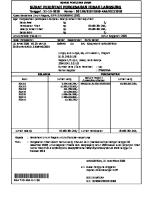
Hub Model Designation System Figure 1 (Sheet 1)
60-00-00 © McCauley Propeller Systems
Page 3 Oct 19/2015
McCAULEY PROPELLER SYSTEMS
SPM100 STANDARD PRACTICES MANUAL
Hub Model Designation System Figure 1 (Sheet 2)
60-00-00 © McCauley Propeller Systems
Page 4 Oct 19/2015
McCAULEY PROPELLER SYSTEMS
SPM100 STANDARD PRACTICES MANUAL
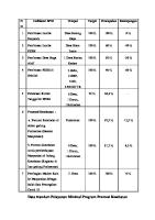
Blade Model Designation System Figure 2 (Sheet 1)
60-00-00 © McCauley Propeller Systems
Page 5 Oct 19/2015
McCAULEY PROPELLER SYSTEMS
SPM100 STANDARD PRACTICES MANUAL CLEANING PROCEDURES 1.
General A.
Cleaning Procedures
CAUTION: Do not clean any McCauley propeller part with a steel brush, other metal brush, hard bristle brush, or tool of any type not specified. CAUTION: As applicable during cleaning procedures, observe allowable dimension limits established for certain parts. (1) (2) (3)
Remove dirt, paint (when applicable), grease and oil from all disassembled metal parts of propeller. Use McCauley approved cleaning mediums only (Refer to Table 701). Clean all small, highly finished parts separately. (a) Be careful not to damage small metallic parts, especially on working faces. (b) Clean nonmetallic parts (except gaskets, packings, and seals) by wiping with a soft, lintfree cloth dampened with an approved cleaning medium. (c) Remove thick or packed-on grease or dirt with a soft brush. (d) Allow cleaned parts to air dry. NOTE:
(4)
Protect cleaned parts from collecting dust and dirt during storage or during handling at overhaul. NOTE:
2.
Remove excess moisture with a gentle stream of clean, dry compressed air keeping nozzle of air hose well away from parts.
Keep small parts in transparent plastic bags.
Paint Removal (Metal Parts Only) A.
Paint Removal Immersion Process
CAUTION: Do not use chemical strippers on composite propeller parts, chemical strippers can damage composite components NOTE:
(1) (2) B.
Use of a chemical stripper on metal parts must be in accordance with one of the following specifications: 1. MIL-R-81294 Type II, as detailed in McCauley QPL-81294-26 or approved equivalent. 2. Technical Order (T.O.) 1-1-8, Paragraph 2.6.3.
Soak the part to be stripped completely below solution level. (a) The part must remain immersed in the solution for the time necessary to completely loosen the paint film (one half hour to several hours). Remove the loose paint with a water rinse or a pressurized water spray. (a) The part must be completely clean after rinsing with no residual contamination.
Paint Removal Process by Spray or Brush Application (1) Spray or brush the applicable stripper to the desired surface to be stripped. Apply the stripper by starting at the top and working down. Allow the first application of the stripper to remain on the surface for a sufficient time period to loosen or lift the paint. (2) Use a nonmetallic brush and/or scrape with a plastic or rubber tool to remove the paint film softened by the paint stripper. Apply a second application of stripper reagent and allow it to remain on the surface for a sufficient amount of time to soften or lift the remaining paint film.
60-00-01 © McCauley Propeller Systems
Page 701 Oct 1/2019
McCAULEY PROPELLER SYSTEMS
SPM100 STANDARD PRACTICES MANUAL (3)
After removing all of the paint film, the surfaces must be cleaned of all stripper residues. The residues may be removed with a water spray or manually wiped with water and a clean shop towel. Excess water must be removed from the work piece and the surface must receive a final wipe-down with an approved solvent per Table 701. NOTE:
(4) C.
MIL-R-81294, Type II reagents contain water-reactive constituents. Consequently, the water rinse and drying process must be performed in a continuous and rapid process in order to prevent pitting of the aluminum substrate.
If hard paint remains, repeat the operation.
Plastic Media Blasting
CAUTION: Use plastic media blasting (PMB) only to clean parts and remove paint or epoxy. CAUTION: Etch aluminum parts to remove anodize or color chemical film coating after being chemically stripped of paint or plastic media blasting and before dye penetrant inspection. Aluminum parts which have been etched must be rechemically coated before being returned to service. CAUTION: The work piece can be damaged, or a tight crack be peened over, if PMB system air pressure is increased beyond manufacturer's approved limit, or if the nozzle is held too close to the part. (1)
Within the following general guidelines, McCauley Propeller Systems approves plastic media blasting (PMB) for cleaning and stripping paint and epoxy from parts during propeller repair, reconditioning, or overhaul. (a) Establish standard procedures and controls to protect work piece. (b) Train operator for capable, consistent performance: 1 In handling the nozzle 2 In maintaining correct air pressure, impingement angle, and dwell time 3 In following safety precautions In avoiding media contamination 4 (c) Use periodic test specimens to verify quality control. (d) Examine parts frequently for signs of metal abrasion caused by high air pressure or unusually abrasive plastic media. If metal abrasion is found, damage may be repaired within limits of existing repair tolerances and procedures. (e) Unless the chemical composition of the material being stripped is known to be safe, waste material should be considered hazardous and disposed of in an appropriate manner.
CAUTION: Plastic media blasting can have a detrimental effect on anodic coating or corrosion prevention coatings. Even though an anodized surface appears satisfactory after blasting, its actual corrosion resistance could be degraded. Therefore, all parts must be anodized or have color chemical film treatment applied during overhaul following PMB. (2)
(3) (4)
Topcoat and primer shall be removed using plastic media conforming one of the following specifications. (a) Mil-P-85891, Type II, Size 30/40, or an approved equivalent (b) Mil-P-85891, Type VIII, Size 30/60 The PMB procedure is to be performed with nozzle distance of four to six inches (100 to 150 mm). The nozzle is to be at less than 90 degrees to the part.
60-00-01 © McCauley Propeller Systems
Page 702 Oct 1/2019
McCAULEY PROPELLER SYSTEMS
SPM100 STANDARD PRACTICES MANUAL (5)
Air pressure is not to exceed 100 psi.
NOTE:
3.
Following plastic media blasting, part must be cleaned with a methyl propyl ketone or acetone to remove media residue prior to liquid penetrant inspection. (Refer to Nondestructive Inspection Procedures, Fluorescent Dye Penetrant Inspection, 60-00-03).
Paint Removal (Composite Parts) A.
Composite surface paint and primer removal. (1) Remove old/existing paint by mechanically removing with aluminum oxide sandpaper. NOTE: (a)
The use of plastic media blasting (PMB) is not approved for use on composite propeller blades.
Manual paint removal. 1 Start the sanding operation with a coarse grit aluminum oxide sandpaper, 80 grit is the coarsest grit recommended for paint removal. NOTE:
2 3
Prior to exposing the primer/surfacer, finish the paint removal with a 180 grit sandpaper. Prior to exposing the fiberglass composite material, finish the primer/surfacer, removal with 400 grit sandpaper. Sand until the existing surfacer is uncovered. Do not sand through the original surfacer and into the composite material. NOTE:
(2)
(3) (4)
4.
It is permissible to use a powered circular or random orbit sander (or similar type palm sander for paint removal). Do not use a belt sander for paint removal.
If the propeller is being overhauled, the paint and the sanding surfacer will need to be removed, do not sand into fiberglass composite material. If the propeller is not to be overhauled, removing all of the primer/surfacer is not required.
Clean the propeller surface to be painted. (a) Manually wipe the propeller with a clean cloth wet with MPK. (b) Rotate the cloth frequently to expose a clean cloth surface to wipe the propeller with. (c) Dry the wiped surface with a clean cloth. (d) Rotate the drying cloth frequently to expose a clean cloth surface to dry the propeller with. Examine the composite surfaces for exposed or broken surface fibers. If broken or exposed fibers are detected, refer to the BOM200 Blade Overhaul Manual, Inspection Procedures for propeller damage disposition. Check the balance of the propeller blades, refer to Balancing Procedures for procedures to check the balance of the propeller. Note the propeller blade that is "light" or underweight. (a) If one blade is heaver than the others, apply a thicker coat of sanding surfacer to the lighter blade(s).
Pre-Cleaning Procedures A.
Use the following recommended procedures to pre-clean hub or blade in preparation for removing corrosion, staining, fretting, discoloration, foreign matter, or sealants not removed from hub interior surfaces or blade butt by approved cleaning medium.
60-00-01 © McCauley Propeller Systems
Page 703 Oct 1/2019
McCAULEY PROPELLER SYSTEMS
SPM100 STANDARD PRACTICES MANUAL
CAUTION: In addition to being cleaned with approved medium, hub or blade may have to be further cleaned by plastic media blasting. After plastic media blast, etch per nondestructive inspection procedures, Section 60-00-03, prior to dye penetrant application. CAUTION: Hub and blades of propeller must be thoroughly cleaned prior to inspection procedures. CAUTION: Do not remove any metal from hub while removing sealant residue from stud holes. CAUTION: Do not soak the entire hub in lacquer thinner or plastic media blast unless the phenolic bushing has been removed or is protected (as required). (1)
Tap each hole with an undersize, fine thread tap (9/16-18 NF GH1 or 1/2-20 NE GH1) to remove sealant residue from stud holes as applicable. NOTE:
(2) (3) (4) (5)
For C405 tapped holes, use a 9/16-18 UNF GH3 HS tap ground to an outer diameter of 0.560 to 0.561 inch (14.22 to 14.25 mm). Hold between centers.
Soak hub in approved pre-cleaning medium long enough to loosen all decals, grease and oil. Remove hub from pre-cleaning medium and scrub clean with nonmetallic brush. Soak hub in approved solvent as required to remove adhesive residue from hub. A plastic scraper may be used to help remove any residue. DO NOT use any type of metal scraper on hub. Plastic media blasting of the hub socket area or wear shim recess to remove residue of Teflon sleeve or epoxy is highly recommended but optional.
CAUTION: Do not exceed the 10 minute limit. (6)
Cleaning with vapor degreaser at 240° to 260°F (115° to 127°C) for 8 to 10 minutes is highly recommended but optional.
Table 701. Approved Solvent and Cleaning Medium Applications Medium
Application
Stoddard Solvent Mil-PRF-680, Type II, or an approved equivalent.
to clean any metal surface
Methyl-propyl-ketone (MPK) or Acetone or equivalent
to clean metal surface prior to application of sealant to soften adhesion line between deice boot and blade to clean slip ring assembly to remove residual deice boot cement from blade to remove residual adhesive from around Teflon sleeve insert to remove residual adhesive from around wear shim
Perchlorethylene
to clean aluminum part prior to dye penetrant inspection
Paint Remover MIL-R-81294
to loosen and remove paint and grease
60-00-01 © McCauley Propeller Systems
Page 704 Oct 1/2019
McCAULEY PROPELLER SYSTEMS
SPM100 STANDARD PRACTICES MANUAL Table 701. Approved Solvent and Cleaning Medium Applications (continued) Medium
Application
Lacquer Thinner
to loosen grease on hub to loosen/remove general adhesives and sealants to loosen and remove decals to loosen adhesive from under Teflon sleeve insert
Plastic Media Blasting (PMB)
5.
to strip paint from parts (refer to instructions in this section for general guidelines to clean parts)
Aluminum Blade Pre-Cleaning
CAUTION: If blade has lead wool in the small balance hole in the blade shank, follow the procedure for lead wool removal before starting blade pre-cleaning procedures. A.
Make sure dirt and, if applicable, lead wool have been removed from the 0.75 inch (19.1 mm) balance hole in each blade shank.
B.
Lead Wool Removal: (1) Use a 0.750 inch (19.1 mm) drill bit that has been ground down to 0.745 inch (18.9 mm) diameter for removing lead wool. The end of the drill bit must be ground to an approximate full radius to match the bottom of the hole. (2) Use the drill bit to remove all lead wool from the balance hole and thoroughly clean.
WARNING: The water used in removal of lead wool is a hazardous material with lead contamination. Use an approved method for disposal. (3)
An alternative method for removal of lead wool is a water jet method. (a) Equipment required: 1 Water jet system with capacity that does not exceed 5000 psi. Water supply with no more than two parts per million of chlorides and filtration to 2 remove lead and other particles. (b) Modify blade holding fixture to hold blade firmly in a horizontal position. (c) Attach a 0 degree nozzle head to the cleaning wand of the water jet system. NOTE: (d) (e)
Always wear protective clothing and ear protection. DO NOT stand in front of the water jet nozzle.
Set regulating valve of water jet system to supply necessary pressure to remove lead. Apply water pressure to the lead wool in blade bore for approximately 20 seconds or until lead wool is removed. Repeat as needed to remove lead wool.
C.
Remove any helicoils that are installed in the propeller blade before the blade is soaked in a solvent.
D.
Loosen paint, grease, oil, and sealants or adhesives on blades by soaking them in an approved precleaning medium.
E.
C650 and C750 series propellers may need to undergo the following additional cleaning procedures to remove lock patch material from actuating pin screw holes: (1) Pour MPK in screw hole and allow to stand for 10 minutes. (2) Swab out solvent with clean cotton swab. (3) Dry hole with high-pressure air. (4) Check holes for indications of remaining lock patch.
60-00-01 © McCauley Propeller Systems
Page 705 Oct 1/2019
McCAULEY PROPELLER SYSTEMS
SPM100 STANDARD PRACTICES MANUAL (5)
Install a dummy screw to ensure the hole is clean. Screws should be able to be installed entire length of hole with finger torque only. If screw binds up in hole before reaching bottom, remove screw and continue cleaning the hole. NOTE:
(6)
6.
Dummy screws are non-patch screws of the same size and length as the lock patch screws, and should be identified in some way (head painted red, drilled head, etc.) to make sure they are not left in during reassembly. Dummy screws can be made from used lock patch screws, if the patch has been completely removed from the screw threads.
Repeat Steps (1) through (5) as required until lock patch is completely removed from screw hole.
F.
Clean blade surfaces with a nonmetallic brush and/or plastic rubber scraper.
G.
Thoroughly rinse cleaned blades with tap water and a soft brush.
Composite Blade Pre-Cleaning
CAUTION: If blade has lead wool in the balance tube in the blade shank, follow the procedures for lead wool removal before starting blade pre-cleaning procedures. CAUTION: Do not attempt to tamp wool or remove previously tamped wool from balance tube with tube installed in the blade actuating cup or damage to the blade may occur. A.
Remove the balance tube from the propeller blade, refer to Figure 701. (1) Remove the balance tube. (a) Remove the spiral retaining ring in the blade actuating cup that secures the balance tube to the actuating cup. (b) Thread a screw with a 10-32 UNF thread and at least a 0.5 inch (13 mm) long into the blade plug that is attached to the balance tube. Do not tighten the screw more than 0.2 inches (5 mm) into the Blade Plug, or you may damage the plug. (c) Grab the head of the screw with a pliers and pull the balance tube from the propeller blade. (d) Retain the balance tube and retaining ring for reinstallation. (2) Visually examine the blade bore area for delamination or damage. If any indications of delamination or damage is found, contact McCauley Product Support for disposition and possible repair instructions.
B.
Make sure dirt and, if applicable, lead wool have been removed from each propeller blade balance tube.
C.
Lead Wool Removal: (1) Use a 0.750 inch (19.1 mm) drill bit that has been ground down to 0.745 inch (18.9 mm) diameter for removing lead wool. The end of the drill bit must be ground to an approximate full radius to match the bottom of the tube. (2) Use the drill bit to remove all lead wool from the balance tube and thoroughly clean.
WARNING: The water used in removal of lead wool is a hazardous material with lead contamination. Use an approved method for disposal. (3)
An alternative method for removal of lead wool is a water jet method. (a) Equipment required: 1 Water jet system with capacity that does not exceed 5000 psi. 2 Water supply with no more than two parts per million of chlorides and filtration to remove lead and other particles. (b) Make a fixture to hold the balance tube firmly in a horizontal position.
60-00-01 © McCauley Propeller Systems
Page 706 Oct 1/2019
McCAULEY PROPELLER SYSTEMS
SPM100 STANDARD PRACTICES MANUAL
Composite Blade Balance Tube Removal Figure 701 (Sheet 1)
60-00-01 © McCauley Propeller Systems
Page 707 Oct 1/2019
McCAULEY PROPELLER SYSTEMS
SPM100 STANDARD PRACTICES MANUAL (c)
Attach a 0 degree nozzle head to the cleaning wand of the water jet system. NOTE:
(d) (e)
Always wear protective clothing and ear protection. DO NOT stand in front of the water jet nozzle.
Set regulating valve of water jet system to supply necessary pressure to remove lead. Apply water pressure to the lead wool in blade balance tube for approximately 20 seconds or until lead wool is removed. Repeat as needed to remove lead wool.
D.
Loosen paint, grease, oil, and sealants or adhesives on blades with an approved pre-cleaning medium.
E.
Clean blade surfaces with a nonmetallic brush and/or plastic rubber scraper.
F.
Thoroughly rinse cleaned blades with tap water and a soft brush.
G.
Balance tube installation (1) Install the propeller blade balance tube plug and balance tube after propeller blade inspection is complete. (a) Put plug in balance tube with new O-ring. (b) Secure plug to balance tube with retaining ring. (c) Secure balance tube assembly to propeller blade. Install new O-rings on balance tube. 1 2 Push balance tube into position in the propeller blade actuating cup. 3 Secure balance tube to propeller blade with spiral retaining ring.
60-00-01 © McCauley Propeller Systems
Page 708 Oct 1/2019
McCAULEY PROPELLER SYSTEMS
SPM100 STANDARD PRACTICES MANUAL INSPECTION CRITERIA 1.
Definitions of Defects and Damage A.
Brinelling is the occurrence of shallow, spherical depressions in a surface, usually produced by a part having a small radius in contact with the surface under high load.
B.
A Burr is a small, thin section of metal which extends beyond the edge of a regular surface and usually is located on a corner of, or on the edge of, a bore or hole.
C.
BVID - Barely Visible Impact Damage, impact damage that is barely visually detectable without the use of a magnifying glass.
D.
Corrosion is the loss of surface metal by a chemical or electrochemical action, and the resulting product (for example, iron rust) usually can be removed mechanically.
E.
A Crack is an irregularly shaped separation within a material at a location of excessive stress and usually is visible as a thin line across the surface of the material.
F.
A Cut is a mechanical loss of material (e.g., by saw blade, chisel, or glancing blow of a sharp-edge stone), usually extending to a significant depth over a relatively long, narrow area.
G.
Delamination is the failure of the bond between laminate layers, this failure can be caused by matrix breakdown, repeated cyclic stress, or impact damage.
H.
A Dent is a depression in a material surface caused by an object striking the surface with force. NOTE:
The surface around the dent usually will be sightly deformed.
I.
Distortion or Bending is the alteration of a component's original size or shape.
J.
Erosion is the gradual wearing away or deterioration of a material due to action of the elements.
K.
Exposure is leaving a material open to action of the elements.
L.
Fretting is the occurrence of shallow, spherical surface depressions, usually caused by vibratory ("chattering") action or by a part which has a small radius in contact under high load with the material.
M.
Galling (or burnishing) is the breakdown (or buildup) of a material surface resulting from excessive friction between two moving parts. NOTE:
Particles of the softer material will tear loose (breakdown) and weld to the surface of the harder material (buildup).
N.
A Gouge is a small surface area where material has been removed by contact with a sharp object.
O.
Impact damage occurs either in-flight or on the ground when a propeller blade or hub assembly strikes or is struck by an object.
P.
An Inclusion is the presence of an unspecified material that was introduced into a portion of stock material during manufacturing processes such as rolling, forging, or molding.
Q.
A Nick is a localized break or edge notch, usually with displacement of (rather than loss of) material.
R.
Pitting is seen as a number of extremely small (possibly deep) gouges, usually with defined edges, caused by wear and/or deterioration on the surface of a material.
S.
A Score is deeper than a Gouge and may show discoloration from the temperature produced by friction from contact under pressure.
T.
A scrape is a localized break or edge notch, usually with the loss of material that is the result of multiple impacts.
U.
A Scratch is an elongated Gouge.
V.
A Stain is a localized color change noticeably different from the surrounding surface area. Stains can be caused by foreign object deposits (usually benign) to chemical changes in the material caused by chemical contact or burn/heat damage (not benign).
60-00-02 © McCauley Propeller Systems
Page 601 Oct 19/2015
McCAULEY PROPELLER SYSTEMS
SPM100 STANDARD PRACTICES MANUAL
2.
General Inspection A.
Visual and Measurement (1) Visually inspect all parts for damage. (2) Check all threads for rough edges and irregularities. (3) Check that the surface finish (anodize, plating, paint, etc.) is not broken, chipped, or peeling (if peeled look for corrosion). (a) Staining and slight surface markings are normal and not alone cause for rejection or replacement, unless otherwise specified. (4) Measure bores and diameters to be within the limits as specified in propeller overhaul manuals. (5) Inspect hubs per Section 61-11-02, Hub Inspection. (6) Inspect blades per the applicable Blade Overhaul Manual. NOTE: (7)
The threaded portion of blade holding fixtures must be visually checked for nicks, burrs or other damage which could result in a scratched blade thread.
Inspect Piston Rod. The rod may be returned to service as is provided the following criteria are met: (a) Chrome plating and cadmium plating must not be penetrated. (b) The rod at maximum wear location measures no smaller than the minimum diameter specified in the applicable overhaul manual. NOTE:
(8)
Any wear beyond these limits requires the rod be either re-plated per Section 60-00-04, Protective Treatments, or replaced, depending on its repairability.
Inspect Blade Actuating Pins. NOTE:
For blade actuating pins used in 3400 model series propellers, refer to the MPC3400 Series Overhaul Manual, Section 61-14-01, Inspection/Check and the BOM200 Blade Overhaul Manual, Section 61-15-00, Inspection Procedures, for blade actuating pin inspection instructions.
(a) (b)
(9)
The pins should have a smooth glossy finish in the area contacting blade actuating links. A dull or rough surface finish in this area can cause increased wear, elongating holes in the phenolic bushing of the link. (c) Pins with a dull or rough finish may be lightly polished with a crocus cloth. (d) If a smooth glossy surface finish cannot be obtained the blade actuating pin must be replaced. Inspect all new and used blade retaining rings. Use a radius gauge to inspect both sides of the inner diameter corner radius, to make sure the distance from the inner surface to the flat on the flat surface is not more than 0.016 inch, (Refer to Figure 601).
NOTE:
The ring inner surface is not necessarily square with the top and bottom surfaces. The McCauley factory has found that a standard 1/64 inch radius gauge with scribed lines is an adequate and acceptable method to inspect the retaining ring.
(10) Inspect O-rings for flashing (excess material left from the molding process). Faulty O-rings must be replaced. (11) Inspect B-5269 Washer, for sharp edges on the inside diameter. (a) Inspect B-5269 Washers for adequate radius on the inside diameter. (b) A sharp edge could damage the counterweight bolt in the critical radius area of the bolt head. (c) B-5269 Washers manufactured since 1985 have a 0.030 to 0.045 inch (0.76 to 1.14 mm) radius on one side of the washer inside diameter. Washers must be inspected and those washers without the 0.030 to 0.045 inch (0.76 to 1.14 mm) radius must be replaced with the current washer. (12) Inspect all other parts per the applicable propeller overhaul manual.
60-00-02 © McCauley Propeller Systems
Page 602 Oct 19/2015
McCAULEY PROPELLER SYSTEMS
SPM100 STANDARD PRACTICES MANUAL
Blade Retaining Ring Inspection Figure 601 (Sheet 1)
60-00-02 © McCauley Propeller Systems
Page 603 Oct 19/2015
McCAULEY PROPELLER SYSTEMS
SPM100 STANDARD PRACTICES MANUAL
3.
B.
Inspect aluminum parts using dye penetrant methods. Inspect steel parts using magnetic particle inspections, unless otherwise stipulated. All dye penetrant and magnetic particle inspection is to be done per Section 60-00-03, Non Destructive Inspection.
C.
Inspect Cylinder Supports for cracks along the edge of the inner hole where the cylinder support is mounted on the piston rod. Such cracks are in a non-critical area and will not propagate. Cracks in this area are permitted to a 0.030-inch (0.76 mm) maximum depth on this surface only. A maximum of four cracks are permitted with 0.250-inch (6.35 mm) minimum spacing between the cracks.
Spring Rate Test A.
Refer to Table 601 for required spring dimensions and loads that are applicable to each listed spring. The springs shall be tested in the following manner: (1) Compress the spring to "Height A" NOTE:
(2)
Spring "Height A" is the height of a maximum spring compression, do not compress the spring more than "Height A"
(a) Make sure the spring can be compressed to the height specified in "Height A" Release pressure on the spring until you have reached the compressed "Length 1" (a) Make sure the force required to maintain "Length 1" is at least or within the range given within "Load 1" limits. NOTE:
(3)
Take each of the spring rate measurements with the spring extending/pressure being taken off of the spring.
Release pressure on the spring until you have reached the compressed "Length 2" NOTE: (a)
Take each of the spring rate measurements with the spring extending/pressure being taken off of the spring.
Make sure the force required to maintain "Length 2" is at least or within the range given within "Load 2" limits.
Table 601. Spring Rate Dimensions and Values Part Number
Compressed Length 2 (Inches)
Height A (Inches)
Compressed Length 1 (Inches)
Load 1 (Pounds)
A-3125
3.313 (84.15 mm)
3.580 (90.93 mm)
282 - 345 (1254 to 1535 N)
4.930 (125.22 mm)
146 - 179 (649.44 to 796.23 N)
A-3268
5.939 (150.85 mm)
6.027 - 6.047 (153.09 to 153.59 mm)
257 - 273 (1143 to 1214 N)
8.430 to 8.450 (214.12 to 214.63 mm)
132 - 148 (587 to 658 N)
A-3269
5.927 (150.55 mm)
6.027 to 6.047 (153.09 to 153.59 mm)
307 to 323 (1366 to 1437 N)
8.430 to 8.450 (214.12 to 214.63 mm)
212 to 228 (943 to 1014 N)
A-3553
5.939 (150.85 mm)
6.027 to 6.047 (153.09 to 153.59 mm)
283 to 299 (1259 to 1330 N)
8.430 to 8.450 (214.12 to 214.63 mm)
158 to 174 (702 to 774 N)
A-4501
3.094 (78.59 mm)
3.130 to 3.150 (79.5 to 80.01 mm)
283 to 299 (1259 to 1330 N)
4.488 to 4.508 (114.00 to 115.50 mm)
140 to 156 (623 to 694 N)
Load 2 (Pounds)
60-00-02 © McCauley Propeller Systems
Page 604 Oct 19/2015
McCAULEY PROPELLER SYSTEMS
SPM100 STANDARD PRACTICES MANUAL Table 601. Spring Rate Dimensions and Values (continued) Part Number
Compressed Length 1 (Inches)
Load 1 (Pounds)
Compressed Length 2 (Inches)
Height A (Inches)
A-4502
2.870 (72.90 mm)
2.912 to 2.932 (73.96 to 74.47 mm)
272 to 288 (1210 to 1281 N)
4.270 to 4.290 (108.46 to 108.97 mm)
172 to 188 (765 to 836 N)
C-5022
5.700 (144.78 mm)
5.800 (143.32 mm)
1260 to 1450 (5605 to 6450 N)
8.900 (226.06 mm)
760 to 885 (3381 to 3937 N)
B-5104
0.700 (17.78 mm)
0.738 to 0.758 (18.75 to 19.25 mm)
7.18 to 9.18 (31.9 to 40.8 N)
1.530 to 1.550 (38.86 to 39.37 mm)
4 to 6 (17.8 to 26.7 N)
C-5328
5.700 (144.78 mm)
5.800 (143.32 mm)
1562 to 1797 (6948 to 7994 N)
8.900 (226.06 mm)
807 to 938 (3590 to 4172 N)
B-5655
0.378 (9.6 mm)
0.409 (18.01 mm)
7.62 to 8.44 (33.9 to 37.5 N)
0.675 (17.15 mm)
6.25 to 7.20 (27.8 to 32.0 N)
B-5656
0.370 (9.4 mm)
0.409 (18.01 mm)
14.81 to 18.10 (65.8 to 80.5 N)
0.675 (17.15 mm)
11.97 to 13.97 (53.2 to 62.1 N)
B-5657
0.684 (16.97 mm)
0.744 (18.90 mm)
9.75 to 10.32 (43.3 to 45.9 N)
1.032 (26.21 mm)
8.81 to 9.25 (39.1 to 41.1 N)
B-5658
0.704 (17.88 mm)
0.744 (18.90 mm)
38.21 to 44.52 (170 to 198 N)
1.032 (26.21 mm)
30.37 to 35.72 (135 to 159 N)
A-5677
2.750 (69.85 mm)
2.790 to 2.810 (70.87 to 71.37 mm)
265 to 299 (1179 to 1330 N)
4.024 to 4.044 (102.21 to 102.72 mm)
208 to 238 (925 to 1059 N)
B-5701
1.600 (40.64 mm)
1.680 (42.67 mm)
104.21 to 127.37 (464 to 567 N)
2.430 (61.72 mm)
58.34 to 66.64 (260 to 296 N)
C-5932
6.700 (170.18 mm)
6.800 (172.72 mm)
1764 to 2120 (7847 to 9430 N)
9.900 (251.46 mm)
945 to 1170 (4204 to 5204 N)
B-6131
2.181 (55.40 mm)
2.270 to 2.290 (57.66 to 58.17 mm)
25.4 to 28.4 (113 to 126 N)
3.470 to 3.490 (88.14 to 88.65 mm)
19.2 to 21.0 (85.4 to 93.4 N)
B-7045
2.405 (61.09 mm)
2.590 to 2.610 (65.79 to 66.29 mm)
35.9 to 40.5 (160 to 180 N)
3.740 to 3.760 (95.00 to 95.50 mm)
22.0 to 24.8 (97.9 to 110 N)
4.
Load 2 (Pounds)
Mandatory Part Retirement Procedures A.
The blades, hubs, bearing races, and split retainers may be serialized to aid correct assembly and to prevent reuse of parts which have been retired from service.
B.
When a McCauley serialized part no longer meets airworthiness standards, use the following procedure to retire the part from service and prevent its being returned to service. (1) Attach scrap tag to part. (2) With written permission from owner of part, damage part to make using it impossible. (3) With written permission from owner of part, stamp a letter "S" over the Type Certificate ("TC") number.
60-00-02 © McCauley Propeller Systems
Page 605 Oct 19/2015
McCAULEY PROPELLER SYSTEMS
SPM100 STANDARD PRACTICES MANUAL (4)
Use the McCauley Part Retirement Form (at the end of this section) to record and report all required information about retired part. NOTE:
(5) (6) 5.
Part Retirement Forms may be photocopied and used
Record serial number(s) of part(s) retired. Record how part was disposed of.
Overspeeding or Overtorqueing of Propellers A.
Overspeed damage occurs when the propeller hub assembly rotates at a speed greater than the maximum speed for which it is designed. Following are inspection criteria for McCauley propellers involved in overspeed conditions . Follow the inspection requirements per the following categories for overspeeding of rated take-off RPM. Disregard length of time at overspeed except C1101 thru C1104.
Table 602. Overspeed Inspections Models
Inspection
Overspeed Percentage
Action to be Taken
All Propellers on Reciprocating Engines except 3400 Series propellers
Up to, but not including 15 percent
General external visual inspection.
15 percent or Higher Contact McCauley Product Support for disposition.
Reciprocating Engine 3400 Series propellers
Up to, but not including 10 percent
General external visual inspection.
10 percent or Higher Contact McCauley Product Support for disposition.
All Propellers on Turbine Engines except C1101, C1102, C1103, and C1104
Up to, but not including 10 percent
General external visual inspection.
10 percent or Higher Contact McCauley Product Support for disposition.
Up to, and including 6 percent
Up to 5 minutes operation is permitted
Operation beyond 5 minutes may require some inspection. Contact McCauley Product Support for disposition.
Teardown inspection is required.
Record all details of the overspeed event and contact McCauley Product Support for disposition.
C1101, C1102, C1103, and C1104
Above 6 percent
B.
Overtorquing NOTE: (1) (2) (3)
Overtorque only applies to C1101 thru C1104 model propellers.
Engine Overtorque up to and including 101 percent - maximum continuous operation permitted. Engine overtorque of between 102 percent to 110 percent is permissible for up to 30 seconds duration, provided no condition is section 3 also occurs. McCauley should be contacted and given exact operating conditions for determination of corrective action for engine overtorque during one or more of the following conditions: (a) 111 percent torque or higher. (b) Overtorque during ground operations. (c) In-flight overtorque of between 102 percent and 110 percent for more than 30 seconds (d) Overtorque of between 102 percent and 110 percent for less than 30 seconds under the following: Banked turns of more than 45 degrees. 1 2 Yaw of more than or equal to 2/3 ball. (e) Any overtorque condition outside above criteria.
60-00-02 © McCauley Propeller Systems
Page 606 Oct 19/2015
McCAULEY PROPELLER SYSTEMS
SPM100 STANDARD PRACTICES MANUAL
6.
Normal Criteria for Static Blade Shake and Twist of All Variable Pitch Propellers A.
BLADE SHAKE: Blade shake is defined as follows: (1) The tendency for the propeller blades to wobble slightly when the tip is physically moved by hand, lead edge to trail edge; (Refer to Figure 602) is known as blade shake. (a) This tendency is a natural result of the fabrication of parts within the McCauley retention system. While accumulation of tolerances is measured in thousandths of an inch, it must be remembered that both the parts causing blade shake, and the pivot point about which the blade rotates, are near the blade root. As a result, very small differences at the blade root will be magnified many times when measured at the tip. Total maximum allowable movement up to 0.125 inch (3.13 mm) is considered normal. 1 2 C1100 series propellers may have a maximum movement of 0.1875 inch (4.7 mm). (2) Normal blade shake (less than maximum allowable movement) is no cause for concern, as it disappears during propeller rotation due to the high centrifugal forces acting on the blades (20,000 to 45,000 pounds. (89,000 to 200,000 N)). (a) If blade shake exceeds maximum movement allowable, it should be reduced, when convenient, by inserting shims in the blade assembly by an FAA-approved propeller repair person or international equivalent. (b) In many cases, adjustment can be performed with the propellers still installed on the aircraft. Refer to the appropriate propeller overhaul manual for instructions on installing shims.
B.
BLADE TWIST: Two Categories of Blade Twist exist. They are defined as follows: (1) Rotational play is defined as the sum total of rotational movement a propeller blade allows when moved by hand around its axis of rotation (Refer to Figure 602). (a) This movement is, to a limited degree, considered normal and should not be cause for concern. All blades in a propeller should have about the same amount of rotational play. (b) If the difference in rotational play between two blades is beyond 1.0 degree, uneven internal wear and/or damage is the possible cause. EXAMPLE:
Rotational movement of No. 1 blade measures 1.2 degrees, and No. 2 blade measures 2.3 degrees. This would be considered excessive since their difference is beyond 1.0 degree.)
(c) (2)
The cause of the excessive difference should be determined by an FAA approved propeller repair person or international equivalent at the next opportunity. Blade angle split is a measurement of the angle differences between all the blades in the same propeller. This value is much more critical than rotational play described above, as a high blade angle split may indicate internal problems. While such angle split is very rare, the operator may want to measure it if a problem is suspected, most notably by a marked increase in propeller vibration levels. Blade angle split may be checked as follows: (a) By hand, twist all feathering blades toward high pitch. By hand, twist all non-feathering blades toward low pitch. This will eliminate any play in the propeller linkage, and reduce the possibility of a false angle reading. (b) Using a propeller protractor at the appropriate reference station, measure the angle of each blade. For all propeller models except 3400 model series propellers: 1 a If measurements differ greatly (more than 0.5 degrees) between blades on the same propeller, excessive wear or damage to internal parts may exist. b If the blade angle split is in excess of 0.5 degrees, the propeller must be overhauled at an FAA approved propeller service station or international equivalent at the next opportunity. 2 For 3400 model series propellers: a If measurements differ greatly (more than 0.2 degrees) between blades on the same propeller, excessive wear or damage to internal parts may exist. b If the blade angle split is in excess of 0.2 degrees, the propeller must be overhauled at an FAA approved propeller service station or international equivalent at the next opportunity.
60-00-02 © McCauley Propeller Systems
Page 607 Oct 19/2015
McCAULEY PROPELLER SYSTEMS
SPM100 STANDARD PRACTICES MANUAL
7.
Governors Exposed to Propeller Ground Strike, Propeller/Engine Lightning Strike, Engine Detonation, Oil Contamination, or Sudden Engine Stoppage A.
8.
Any governor exposed to propeller ground strike, propeller and/or engine lightning strike, oil contamination, engine detonation, or sudden engine stoppage must be repaired or overhauled prior to its return to service. Refer to MPC26, Owner/Operator Information Manual, Section 61-00-06, Governors Exposed to Propeller Blade Strike, Propeller/Engine Lightning Strike, Engine Detonation, Oil Contamination, or Sudden Engine Stoppage for additional inspection information.
Lightning Strike Inspection Requirements A.
Determination of Lightning Strike: If doubt exists as to the occurrence of a lightning strike, verify any suspicion using the following criteria: NOTE: (1) (2) (3) (4)
B.
The following definition is intended for use as example only. Determination as to whether or not a "lightning strike" actually occurred is ultimately the responsibility of the operator.
Check for burns or signs of arcing on blades and hub. Using a magnetism detector, check all exposed steel areas of propeller for magnetism. Look for any signs of localized melting or metal flow, particularly on blades. If preliminary inspection suggests an actual strike, the steps detailed in Step 8.B. (below) are to be performed.
Procedure: Complete propeller overhaul is to be accomplished per the applicable propeller overhaul manual. During the overhaul inspection procedure, check propeller components, other than blades, for indications of lightning entrance or exit. (1) Determination: Carefully inspect propeller components (other than blades) for the presence of a small, dark, discolored area. Some erosion and/or localized metal flow (melting) will possibly be present. (2) Correction: Any non-blade components showing signs of damage as described above are considered not airworthy and should be scrapped (3) Inspect all non-damaged steel components for signs of magnetic charge. (a) Determination: Check all suspected components using a standard magnetic detection device. (b) Correction: All components showing any signs of magnetic charge should be completely demagnetized using an FAA approved method or international equivalent. (4) Aluminum blades, inspect blades for indication of lightning entrance or exit. (a) Determination: This damage will be evident, in most cases, by the presence of a small, dark, discolored area. Some erosion and/or localized metal flow (melting) will possibly be present. (b) Correction: All lightning damage indications must be removed from blade prior to return to service as follows: 1 Contact McCauley Product Support for disposition of any burn indications on the propeller shank. All burn indications outboard of the shank must be removed using a mill file, sand paper and/or crocus cloth. Following damage indication elimination, remove an additional 0.020 inch (0.51 mm) 2 of material from the affected area. 3 Following material removal, perform a dye-penetrant inspection on the affected areas per Section 60-00-03, Non Destructive Inspection. 4 If any indications of cracks or other flaws are found, additional material must be removed until all indications are gone. 5 Inspect blade per the Blade Overhaul Manual. If blade is found within dimensional limits, it may be returned to service. (5) Composite blades, inspect blades for indication of lightning entrance or exit. (a) Determination: This damage (lightning strike) will be evident, in most cases, by the presence of a small, dark, discolored area. Some erosion and/or localized material flow (melting) will possibly be present. (b) Examine the leading edge guard for: Damage 1
60-00-02 © McCauley Propeller Systems
Page 608 Oct 19/2015
McCAULEY PROPELLER SYSTEMS
SPM100 STANDARD PRACTICES MANUAL
Blade Shake and Blade Twist Figure 602 (Sheet 1)
60-00-02 © McCauley Propeller Systems
Page 609 Oct 19/2015
McCAULEY PROPELLER SYSTEMS
SPM100 STANDARD PRACTICES MANUAL
(c)
(d)
(e)
Burning indications 2 3 Bond line delamination Examine the propeller blade composite material for: 1 Damage 2 Burning indications 3 Exposed fiberglass and/or carbon fiber Examine the propeller blade deice boot or anti-ice shoe for: 1 Burning indications 2 Damage to the deice leads 3 Bond line delamination between the blade and the deice boot or anti-ice shoe. Examine the propeller blade urethane collar for: 1 Burning indications and/or damage. NOTE:
(f) 9.
Make sure the area on the urethane collar adjacent to the leading edge guard is examined for damage.
Correction: If after the inspection, a lightning strike is suspected, contact McCauley Product Support for additional instructions prior to returning the propeller to service.
Necessary Actions Following Object Strike of Stationary Propeller, Blade Strike of Rotating Propeller, Bird Strike, or Sudden Engine Stoppage A.
Criteria for scrapping hubs following object, blade, or bird strike: (1) A hub must be declared not airworthy and scrapped if any aluminum blade in the propeller assembly is bent beyond repair limits within the first 85 percent of total blade station radius (Refer to Figure 603 and Figure 604). (2) A hub may be returned to service, pending normal overhaul inspection, if any aluminum blade in the propeller assembly is bent beyond repair limits as defined in Blade Overhaul Manual outboard of the 85 percent blade station radius. (3) A hub must be declared not airworthy and scrapped if any composite blade in the propeller assembly is shattered or sheared within the first 85 percent of total blade station radius.
(4)
B.
NOTE:
Shattered or sheared means the propeller impact resulted in the foam core of the propeller blade to be exposed.
NOTE:
The basic design diameter of a propeller assembly is the maximum certified diameter of the propeller for a given application. Always use the maximum certified propeller diameter when determining the disposition of damage to a propeller.
A hub may be returned to service, pending normal overhaul inspection, if any composite blade in the propeller assembly is shattered or sheared outboard of the 85 percent blade station radius. (a) If, during the overhaul inspection, the propeller blade urethane collar, propeller blade actuating pin, or the actuating pin bushing sustained damage that would require their removal from service as a result of the propeller blade impact, the hub must also be declared not airworthy and scrapped.
Object Strike of Stationary Propeller (1) "Object Strike" is defined as any impact of a non-rotating propeller by a substantial moving object, such as any personnel vehicle, aircraft tug, ground power unit, or similar. NOTE:
(2)
The definition is intended for use as an example only. Determination as to whether or not an object strike actually occurred is ultimately the responsibility of the aircraft operator.
Inspect all blades for damage such as scrapes, gouges, etc. caused by the impact. Any damage beyond normal field repair limits is cause for propeller removal and repair as defined below. (a) For propellers with aluminum blades, (except threaded propeller models C01 through C98) refer to the MPC26 Owner/Operator Information Manual Revision 2 (or latest revision) for field repair limits.
60-00-02 © McCauley Propeller Systems
Page 610 Oct 19/2015
McCAULEY PROPELLER SYSTEMS
SPM100 STANDARD PRACTICES MANUAL
Bent Blade Criteria for Threadless Blades Figure 603 (Sheet 1)
60-00-02 © McCauley Propeller Systems
Page 611 Oct 19/2015
McCAULEY PROPELLER SYSTEMS
SPM100 STANDARD PRACTICES MANUAL
Bent Blade Criteria for Threaded Blades Figure 604 (Sheet 1)
60-00-02 © McCauley Propeller Systems
Page 612 Oct 19/2015
McCAULEY PROPELLER SYSTEMS
SPM100 STANDARD PRACTICES MANUAL (b)
(3)
(4)
For propeller models C01 through C98 refer to McCauley Service Letter SL1995-4C (or latest revision) for field repair limits of the propeller blades. (c) For propellers with composite blades, refer to the MPC27 Constant Speed Composite Owner/Operator Information Manual for field repair limits. Check the blade track and verify that all blades measure within the following limits: (a) 0.0625 inch (1.6mm) of each other on piston engine propellers (including C3400 Series propellers). (b) 0.170 inch (4.3mm) of each other on turbine engine propellers (except propeller models C1101 through C1104). (c) 0.1875 inch (4.7mm) of each other on C1101 through C1104 models. Check blade twist. All blades in a propeller should have the same amount of "rotational play". If the difference in rotational play between two blades is beyond 1.0 degree, uneven internal wear or damage is the possible cause. (a) For example, rotational movement of No. 1 blade measures 1.2 degrees and No. 2 blade measures 2.3 degrees. This would be considered excessive since the difference is more than 1.0 degree. This check must be performed every 10 hours for the next 20 hours. If no change is seen after 20 hours, inspections may be discontinued. NOTE:
(5)
The results of an object strike inspection should be noted in the propeller log book and, if required, note when the next inspection is due.
If any propeller blade is damaged beyond field repair limits, the blade track or the propeller blade twist is beyond the limits, contact McCauley for disposition of the propeller assembly.
C.
Procedures on Propellers Following Object Strike: The following inspections must be performed on any propeller experiencing an object strike: (1) Inspect all blades for damage such as scrapes, gouges, etc. caused by the impact. (a) Any damage beyond normal field repair limits (limits defined in McCauley BOM100 or BOM200 Blade Overhaul Manuals as applicable) is cause for propeller removal and repair/ overhaul as defined below. (2) Check blade track per Section 60-00-07. (3) Check blade twist. Refer to Normal Criteria for Static Blade Shake and Twist of All Variable Pitch Propellers (a) This check must be performed every 10 hours for the next 20 hours. (b) If no change is seen after 20 hours, inspections may be discontinued. (c) If the blades do not meet the blade twist criteria, the propeller must be disassembled, and the retention and actuating systems inspected and repaired by an FAA-approved propeller repair person or international equivalent per the applicable propeller overhaul manual.
D.
Blade Strike of Rotating Propeller.
CAUTION: Internal damage can occur without evidence of gross external damage. (1) (2)
Blade Strike, sometimes referred to as Ground Strike, is defined as any impact or suspected impact of the rotating propeller upon such items as, but not limited to, the ground, tow bars, landing lights, carts, snow banks, hedges, etc. The definition is intended for use as example only. NOTE:
E.
Determination as to whether or not a blade strike actually occurred is ultimately the responsibility of the aircraft operator.
Procedures Following Blade Strike of Rotating Propeller: (1) For propellers with aluminum propeller blades: (a) Any McCauley propeller experiencing a Blade Strike must be removed from the aircraft and completely overhauled by an FAA approved propeller repair station or international equivalent in accordance with the applicable propeller overhaul manual. (b) A hub must be declared not airworthy and scrapped if any blade in the propeller assembly is bent beyond the defined repair limits.
60-00-02 © McCauley Propeller Systems
Page 613 Oct 19/2015
McCAULEY PROPELLER SYSTEMS
SPM100 STANDARD PRACTICES MANUAL (2)
For propellers with composite propeller blades: (a) Any McCauley propeller experiencing a Blade Strike must be removed from the aircraft and completely overhauled by an FAA approved propeller repair station or international equivalent in accordance with the applicable propeller overhaul manual. (b) A hub must be declared not airworthy and scrapped if any blade in the propeller assembly is damaged beyond the defined repair limits.
F.
Bird Strike: (1) Bird Strike is defined as the impact of any bird into the rotating propeller, causing damage.
G.
Procedures on Propellers Following Bird Strike: any McCauley propeller experiencing a bird strike must be inspected per the following criteria: (1) Inspect all blades for damage such as scrapes, gouges, etc. caused by the impact. Any damage beyond normal field repair limits (defined in other McCauley service information) is cause for propeller removal and repair as defined below. (2) Check blade track per Section 60-00-07. (a) This is a one time check. If blade track is out, propeller must be overhauled. (3) Check blade twist. Refer to Normal Criteria for Static Blade Shake and Twist of All Variable Pitch Propellers. (a) This check must be performed every 10 hours for the next 20 hours. (b) If no change is seen after 20 hours, inspections may be discontinued. (c) If the blades do not meet the blade twist criteria, the propeller must be overhauled per the applicable propeller overhaul manual by an FAA-approved propeller repair station or international equivalent. (4) If a blade is bent or damaged beyond repair during a bird strike the propeller must be overhauled per the applicable propeller overhaul manual by an FAA-approved propeller repair station or international equivalent. (5) For composite propeller blades, the following additional checks are required following a bird strike: (a) Inspect the propeller blade leading edge guard and blade composite laminate for delamination by conducting a coin tap test. (b) Check the blade urethane collar for damage. (c) Check the blade retaining ring and shims for damage and security. (d) Check the blade actuating pin and actuating bushing for damage.
H.
Sudden Engine Stoppage: (1) Sudden Stoppage is defined as any propeller experiencing a sudden decrease in RPM. (2) This is commonly due to engine failure or seizure. (3) McCauley recommends consulting engine manufacturers' data to determine criteria for sudden engine stoppage. NOTE:
I. 10.
Procedures on Propellers Following Sudden Stoppage: (1) Contact McCauley Product Support for propeller disposition and inspection requirements.
Engine Oil Contamination A.
11.
Determination as to whether or not sudden engine stoppage has occurred is ultimately the responsibility of the aircraft operator.
Any McCauley propeller exposed to contaminated oil must have any gasket or seal exposed to the contaminated oil replaced and any part exposed to the contaminated oil inspected.
Fire Inspection A.
Any McCauley propeller, spinner or governor that has been involved in a fire or shows any indications of exposure to heat damage from a fire (discolored paint, bubbled paint, discolored metal, melted material, etc.) is no longer airworthy and must be removed from service and scrapped.
60-00-02 © McCauley Propeller Systems
Page 614 Oct 19/2015
McCAULEY PROPELLER SYSTEMS
SPM100 STANDARD PRACTICES MANUAL
60-00-02 © McCauley Propeller Systems
Page 615 Oct 19/2015
McCAULEY PROPELLER SYSTEMS
SPM100 STANDARD PRACTICES MANUAL NON-DESTRUCTIVE INSPECTION PROCEDURES 1.
Eddy Current Inspection A.
Threaded Hub Socket Inspection (1) McCauley requires eddy current inspection of all threaded hub sockets be performed in addition to dye penetrant inspection specified in the appropriate propeller overhaul manual. This inspection has been tested and found to be reliable, and is designed to detect cracks in the threaded areas of the hub that may not be visible using dye penetrant alone. (2) Equipment Required (a) Any eddy current instrument capable of operating at a frequency of 200 KHz. (b) Eddy current segmented probe kit part number MC-1 is strongly recommended, and is available from Galactic NDT Services, 10728 S. Pipeline Road, Suite D, Hurst, Texas, 76053, 817-571-6715. Kit MC-1 contains MC-1 Threaded Probe, PF-20 Sharp Pencil Probe, Reference Standard, and Teflon Tape. Eddy current probe kit MC-1 is not a McCauley product. Kit is appropriate for truncated hubs only. (3) Hub Preparation (a) Remove all oil, grease, and sealants and wipe threaded surfaces with approved solvent (Refer to Section 60-00-01, Cleaning Procedures). (b) Inspect threaded surfaces for burrs and other metal obstructions per instructions in Section 60-00-02, Inspection Criteria. Remove burrs and obstructions to prevent binding of the threaded probe during testing. (4) Personnel Requirements (a) Individuals performing inspections defined in this manual must be an employee of an FAA-approved facility (or international equivalent) with a specialized service rating in the applicable inspection method. Employees must be qualified and certified to the minimum recommended requirements of "Level II" as described in Aerospace Industries Standard--NAS 410, or ASNT-SNT-TC-1, or equivalent international standard. (5) Calibration Standard (a) Threaded standard provided in MC-1 probe kit, NIST traceable. 1 EDM Notch size 0.007 inches wide a b 0.050 inches deep c 0.150 inches long (6) Calibration Procedure (Threaded Probe) (a) Calibrate/balance the eddy current instrument in accordance with the instrument manufacturer's instructions. (b) Check or set lift-off using the following instructions: 1 Place a 0.003 inch (0.076 mm) lift-off shim or piece of cellophane tape (Scotch brand transparent or equivalent) on a relatively flat area of the certified calibration standard provided. Place the probe element on the shim or cellophane tape, zero the machine, and slide 2 the probe onto bare metal. 3 Verify that the deflection is in accordance with manufacturer's calibration/balance procedures. (c) To test and set meter deflection: 1 Place probe on threaded section of the certified standard and zero machine. 2 Slide probe slowly over EDM notch and note meter deflection. 3 Adjust instrument gain to display: a For ED-520 eddy current tester, a minimum 70 microampere deflection. b For a Hocking Locator UH and UH-B instrument, 40% deflection. c For all phase analysis instruments, a 50% amplitude signal. NOTE:
Use the threaded probe only on truncated hubs. Non-truncated hubs and other hubs that are smaller in diameter are to be tested with the pencil probe only.
60-00-03 © McCauley Propeller Systems
Page 601 Oct 1/2019
McCAULEY PROPELLER SYSTEMS
SPM100 STANDARD PRACTICES MANUAL (7)
Scanning and Indexing (Threaded Probe) (a) Place hub socket to be tested in upright position. NOTE: (b) (c)
Stabilize temperature of hub and probe at 72 to 80°F (22 to 27°C) before you test to ensure best fit.
Thread the probe into the hub socket until probe element (the white dot on the side of probe) is no longer visible. Adjust needle on ED-520 to 350, to 0 on Hocking Locator, or to normal lift-off point on phase analysis instrument.
CAUTION: Do not force probe into hub. Excessive downward pressure can cause premature wear on probe. If binding of probe is noticed during test scan, stop test and unthread probe, and inspect hub threads for burrs and other contamination. (d)
(8)
Thread probe slowly into entire hub socket to maintain a stable needle or lift-off point on the instrument. If a stable needle cannot be maintained, install non-metallic shim material in slot behind probe element to improve probe fit. (e) Instrument will normally display a slow shift when probe is twisted. Instrument display will be a rapid deflection or shift if cracks and corrosion are encountered. Evaluation (a) Any rapid indication that exceeds 70 microampere on an ED-520, 40% deflection on a Hocking Locator, or 50% amplitude signal on a phase analysis instrument must be evaluated further. Mark the hub with a non-metallic marker at indications for later reference during 1 evaluation. (b) Verify all indications noted by the threaded probe by scanning with pencil probe and by view with a 10x magnifier. At this point, switch to pencil probe to further evaluate indications noted by threaded probe.
CAUTION: Wrap one layer of Teflon tape, 0.003 to 0.006 inch (0.076 to 0.152 mm) thick, around the first 0.5 inch (13 mm) of the sharp pencil probe to prevent premature wear while scanning the hub socket. (9)
Calibration Procedure (Pencil Probe) (a) Calibrate/balance the eddy current instrument in accordance with the instrument manufacturer's instructions. 1 Use a reference standard that has an 0.020 inch deep EDM notch. The dimensional accuracy of EDM notches shall be documented and traceable to the National Institute of Standards and Technology (NIST) or international equivalent. (b) Check or set lift-off using the following instructions: 1 Place a 0.003 inch (0.076 mm) lift-off shim or piece of cellophane tape (Scotch brand transparent or equivalent) on a relatively flat area of the certified calibration standard provided. 2 Place the probe element on the shim or cellophane tape, zero the machine, and slide the probe onto bare metal. Verify that the deflection is in accordance with manufacturer's calibration/balance 3 procedures. (c) To test and set meter deflection: 1 Place probe on threaded section of the certified standard and zero machine. 2 Slide probe slowly over EDM notch and note meter deflection. 3 Adjust instrument gain to display: a For ED-520 eddy current tester, a minimum 70 microampere deflection. b For a Hocking Locator UH and UH-B instrument, 40% deflection. c For all phase analysis instruments, a 50% amplitude signal.
60-00-03 © McCauley Propeller Systems
Page 602 Oct 1/2019
McCAULEY PROPELLER SYSTEMS
SPM100 STANDARD PRACTICES MANUAL (10) Scanning and Indexing (Pencil Probe) NOTE:
Use light, gentle downward pressure on pencil probe when scanning hub.
(a)
Place probe in threaded section of hub socket and adjust needle on ED-520 to 350, to 0 on Hocking Locator, or to normal lift-off point on phase analysis instrument. (b) Move probe slowly along root of threads to maintain a stable needle or lift-off point on instrument. (c) Instrument will normally display a slow shift when probe is moved. Instrument display will be a rapid deflection or shift if cracks and corrosion are encountered. (11) Evaluation (a) Any rapid indication detected by threaded probe and confirmed by pencil probe that exceeds 70 microampere on an ED-520, 40% deflection on a Hocking Locator, or 50% amplitude signal on a phase analysis instrument requires scrapping the hub. Refer to Part Retirement Procedures and Form, Section 60-00-02, Inspection Criteria. B.
Composite Propeller Blade Cup - Actuating (pin) Inspection (1) McCauley requires eddy current inspection of the composite propeller blade cup - actuating (pin). This inspection is designed to detect cracks in the area adjacent to and in the blade cup actuating (pin). (2) Personnel Requirements (a) Individuals performing this inspection must be an employee of an FAA-approved facility (or international equivalent) with a specialized service rating in the applicable inspection method. Employees must be qualified and certified to the minimum recommended requirements of "Level II" as described in Aerospace Industries Standard--NAS 410, or ASNT-SNT-TC-1, or equivalent international standard. (3) Equipment Required (a) Any eddy current instrument capable of operating at a frequency of 200 KHz. (b) A shielded pencil probe 1 Probe may have an absolute or differential coil arrangement. 2 Probes shall not give interfering response from handling pressures, scanning or normal operating pressure variations on the coil which cause the signal to noise ratio to be less than 3 to 1. (c) Aluminum Reference Standard Standard must have a minimum surface finish of 150 RHR or RMS 165. 1 2 The dimensional accuracy of EDM notches shall be documented and traceable to the National Institute of Standards Technology (NIST). 3 The reference must have an EDM notch that is 0.020 inch (0.508 mm) deep. (d) Teflon Tape, less than 5 mils (0.127 mm) thick. NOTE: (4) (5)
Teflon tape may be used to decrease the wear on the eddy current probe coil. Whenever Teflon tape is used the instrument calibration must be verified.
Blade Actuating Pin Preparation (a) Clean the surface to be inspected, remove all oil, grease, and contaminates with an approved solvent (Refer to Section 60-00-01, Cleaning Procedures). Calibration Procedure (Pencil Probe) (a) Calibrate/balance the eddy current instrument in accordance with the instrument manufacturer's instructions. 1 Use a reference standard that has an 0.020 inch (0.508 mm) deep EDM notch. The dimensional accuracy of EDM notches shall be documented and traceable to the National Institute of Standards and Technology (NIST) or international equivalent. (b) Check or set lift-off using the following instructions: Put the surface probe on the reference standard away from the notch. 1 2 Set the null point. 3 Lift the surface probe from the reference standard and monitor the display for the lift-off response. 4 Adjust the display until the lift-off response goes horizontal and to the left of the null point.
60-00-03 © McCauley Propeller Systems
Page 603 Oct 1/2019
McCAULEY PROPELLER SYSTEMS
SPM100 STANDARD PRACTICES MANUAL 5 6
(6)
(7)
2.
Put the surface probe on the reference standard and move it across the 0.020 inch (0.508 mm) deep EDM notch. Adjust the instrument to get a minimum separation of three major screen divisions between the null point and the applicable reference notch. NOTE:
This adjustment is used to set the sensitivity of the inspection. It is not intended as accept or reject criteria.
NOTE:
Filters may be used to improve the signal to noise ratio.
Inspection (a) Do an eddy current inspection of the propeller blade actuating pin and adjacent area within 1 inch (25.4 mm) of the actuating pin. Make sure the radius area between the pin and the flat surface of the blade cup are inspected. (b) It may be necessary to randomly null the instrument on the blade actuating pin in the area of inspection to adjust the display for differences between the reference standard and the actuating pin. (c) Whenever possible, the area of inspection must be examined in two different directions that are 90 degrees to each other. (d) Examine the inspection area at index steps that are no more than the width of the eddy current test coil. You can do a scan of a part edge as long as the response from edge effect does not hide the calibration notch response. (e) Examine the radius area of the actuating pin in both transverse and parallel to the axis of the radius. Examine the edge of the radius transverse to the axis of the radius. Evaluation (a) If an indication is found, carefully repeat the inspection in the opposite direction of probe movement to make sure of the indication. If the indication is still there, carefully monitor the amount of probe movement or rotation needed to cause the response to move off maximum indication response. (b) If a crack is detected, the propeller blade must be removed from service and scrapped. Refer to Section 60-00-02, Inspection Criteria, Part Retirement Procedures and Form.
Fluorescent Dye Penetrant Inspection A.
General (1) Fluorescent penetrant inspection shall be performed as specified on products manufactured by McCauley Propeller Systems. Penetrant inspection shall be used to detect cracks or discontinuities open to the surface which may not be evident by normal visual inspection. (2) Inspection is performed in accordance with standard ASTME 1417, Standard Practice for Liquid Penetrant Examination.
B.
Personnel (1) Individuals performing inspections defined in this manual must be an employee of an FAAapproved facility (or international equivalent) with a specialized service rating in the applicable inspection method. Employees must be qualified and certified to the minimum recommended requirements of "Level II" as described in Aerospace Industries Standard--NAS 410, or ASNTSNT-TC-1, or equivalent international standard.
C.
Materials and Equipment (Refer to Figure 601). (1) Materials and equipment used to perform inspection are in accordance with QPL-AMS-2644, Qualified Products of Inspection Materials, Penetrant.
CAUTION: Intermixing of penetrant families from various manufacturers is prohibited. (2) (3) (4) (5)
Penetrants used must be Type I, level 3 or 4. Emulsifiers used must be methods B or D. Cleaners/removers must be class 2 for method C. Developers used for method A penetrants must be form a, form c, or form d.
60-00-03 © McCauley Propeller Systems
Page 604 Oct 1/2019
McCAULEY PROPELLER SYSTEMS
SPM100 STANDARD PRACTICES MANUAL (6) (7)
Developers used for methods B and D penetrants must be form a, form b form c, or form d. Developers used for method C must be form d.
D.
Definitions (1) You will find definitions in ASTME 1316-00A, Specification of Terminology for Nondestructive Examinations.
E.
Surface Preparation (1) Clean parts per Section 60-00-01, Cleaning Procedures. (2) Prior to penetrant inspection, the surface to be examined shall be dry and free of all paint, coatings, dirt, grease, lint, oil, or other extraneous matter that could interfere with the examination. Part must be cleaned using a cleaning solvent or vapor degreaser to remove media residue prior to liquid penetrant inspection. (3) The etching process must follow cleaning of the propeller blade or hub to remove paint and coatings. (4) Plug all holes in the part before starting the Caustic Soda Etch process. Use plugs (example; rubber plugs, plastic plugs, or grade 7 titanium hardware) that will keep the etch solutions from contacting the interior surfaces in each plugged hole.
F.
Caustic Soda Etch
CAUTION: Aluminum parts that have had protective coatings removed are susceptible to corrosion. Do not store aluminum parts with the protective coatings removed. Minimize the exposure of unprotected aluminum parts to corrosive environments. NOTE:
Blades and hubs that have been cleaned with plastic media blast must be etched in a caustic solution prior to inspection.
NOTE:
An aluminum part which has been etched in a caustic solution must be anodized or have a chemical film treatment applied before it is returned to service.
CAUTION: Concentration and temperature of the caustic solution and length of time a part is in solution must be carefully controlled to avoid destroying the part by over-etching. CAUTION: Make sure all threaded and close tolerance holes are plugged prior to immersing the part in a caustic soda etch solution. The caustic soda etch can damage close tolerance and threaded holes and will result in the scrapping of the part. (1)
Immerse the part in a solution of Sodium Hydroxide. The Sodium Hydroxide solution shall conform to the following parameters: (a) The concentration of the solution shall be 30 to 90 grams of Sodium Hydroxide (NaOH) for every liter of de-ionized water. NOTE: (b) (c)
The purity/quality of the de-ionized water should be at least of 50,000 ohms of specific resistance (20uS).
Solution temperature shall be kept at 74 to 84°F (23 to 29°C). Immersion time shall be between 3 and 5 minutes.
CAUTION: Do not leave the part in the solution for more than 5 minutes, or damage to the part can occur. NOTE:
An even black appearance is an indication that the coating has been removed.
60-00-03 © McCauley Propeller Systems
Page 605 Oct 1/2019
McCAULEY PROPELLER SYSTEMS
SPM100 STANDARD PRACTICES MANUAL (2) (3)
When a smooth, even coat of black aluminum oxide (smut) appears, immediately remove the part from the solution and rinse thoroughly with tap water. Remove the black aluminum oxide (smut) from the part. (a) Immerse the part in a solution of Nitric Acid. The Nitric Acid solution shall conform to the following parameters: 1 The concentration of the solution shall be 87 to 289 grams of Nitric Acid (HNO3) for every liter of de-ionized water. NOTE: 2 3
The purity/quality of the de-ionized water should be at least of 50,000 ohms of specific resistance (20uS).
Solution temperature shall be kept at 60 to 80°F (16 to 27°C). Immersion time shall be between 2 and 7 minutes.
CAUTION: Do not leave the part in the solution for more than 7 minutes or damage to the part can occur. (4)
Remove the part from the nitric acid solution.
CAUTION: Make sure all acid is rinsed out of bolt holes, dowel holes, balance holes, and hub bore before penetrant application. (a) (b) (c)
Rinse the part immediately with water. Remove plugs from the part. Rinse again and thoroughly with water. Make sure you rinse the interior surfaces of all holes. NOTE:
(d) (e)
De-ionized water is recommended for the final rinse of the part.
Dry all holes with clean, oil-free, compressed air. Part must be completely dry before application of the liquid penetrant.
G.
Penetrant Application (1) Coat entire surface of component in penetrant by dipping, brushing, spraying, or flowing penetrant.
H.
Dwell Time (1) Remove component from penetrant and allow to dwell/drain for an additional 30 minutes. NOTE: (2) (3)
I.
Dipped parts must be allowed to drain for a period at least equal to the period of submersion.
Penetrant shall not be allowed to dry on the part. If penetrant is in danger of drying, apply additional penetrant to make sure the component remains wet. If penetrant does dry or if the dwell time exceeds 2 hours, the component shall be completely recleaned and reprocessed.
Penetrant Removal
CAUTION: The manual water spray used for penetrant and emulsifier removal shall be a coarse spray between 50°F and 100°F (10°C and 38°C), and not greater than 40 psi (275 kPa) with the nozzle approximately 12 inches (300 mm) from the component and at an angle of approximately 45 degrees, while under ultraviolet light to insure the effectiveness of the wash process. (1)
Method A removal process: (a) Remove the penetrant with a coarse water spray.
60-00-03 © McCauley Propeller Systems
Page 606 Oct 1/2019
McCAULEY PROPELLER SYSTEMS
SPM100 STANDARD PRACTICES MANUAL (2)
Method B removal process:
CAUTION: Lipophilic emulsifiers shall not be applied by spray or brush and shall not be agitated while on the surface of the component. (a) (b)
(3)
(4)
J.
Apply a coat of emulsifier over the entire surface of the component by immersion or flowing. Maximum dwell time is 3 minutes. Actual dwell times shall be the minimum necessary to produce an acceptable background on the component. Method C removal process: (a) Remove the surface tension penetrant by wiping with clean white dry cloth. (b) Dampen a clean white cloth with class 1 cleaner/remover and while under an ultraviolet light wipe away any remaining penetrant residue. Method D removal process: (a) Pre-wash the component with coarse water spray. (b) Apply a coat of emulsifier over the surface of the entire part by immersion, flowing, foaming, or spray. When immersion process is used, the emulsifier or part may be mildly agitated. (c) Maximum dwell time is two minutes. Actual dwell time shall be the minimum required for adequate surface penetrant removal. (d) Remove emulsifier/penetrant mixture with a coarse water spray.
Drying
CAUTION: Do not exceed maximum temperature of 160°F (71°C). (1) (2) (3) K.
Dry the component in a forced air dryer until the component is completely dry. Reposition the component as needed in the dryer to prevent water from pooling in pockets and recesses. Remove the dried component from the dryer and allow it to cool until it can be handled.
Developing
CAUTION: Reposition the component so the applied developer shall not be allowed to puddle. Sprayed on developers are not to be applied so heavily that they can mask indications. (1) (2) (3)
The form a developer is applied after the component is dry, to all surfaces to be inspected, with a dwell time of 10 minutes to 4 hours. The form b and form c developers are applied to all surfaces to be inspected by immersion, spray, or flowing after the penetrant removal process, and before the part is dried, with dwell times of 10 minutes to 2 hours. The form d developer is applied after the component is dried by spraying only, to all surfaces to be inspected. The dwell times are 10 minutes to 1 hour.
L.
Examination (1) The examination shall be performed under ultraviolet light in a clean area with a maximum residual visible light of 2 foot-candles (21.53 lux) background. (2) If the interval between penetrant removal and examination exceeds 5 hours or if excessive penetrant background bleed-out is present, the component shall be completely reprocessed from the initial step.
M.
Defect Orientation (1) For threaded propeller hubs, pay particular attention to the inside and outside of the threaded areas nearest the crankshaft flange mount face.
60-00-03 © McCauley Propeller Systems
Page 607 Oct 1/2019
McCAULEY PROPELLER SYSTEMS
SPM100 STANDARD PRACTICES MANUAL N.
Evaluation (1) Any questionable or doubtful penetrant indication shall be wiped away with a cloth or a swab lightly dampened with class 2 cleaner/remover and the area allowed to dry. Reapply a form d developer to the area with the questionable or doubtful indication and allow to dwell for at least 3 minutes. Reexamine this area. If the indication is suspect, McCauley recommends the area be evaluated with eddy current equipment. NOTE:
3.
Reexamination may be done one time only without completely reprocessing the part.
O.
Acceptance Criteria (1) Any verified flaw indications are rejectionable. (2) Any indication which is believed to be non-relevant shall be regarded as a defect and shall be reexamined to verify whether or not actual defects are present. (3) Indications found by penetrant inspection may be ground out or removed by other applicable methods and reexamined by the penetrant inspector, as long as all dimensions are kept within tolerances in the appropriate Propeller Overhaul Manual or Blade Overhaul Manual.
P.
Post Cleaning (1) Residual penetrant and developer must be removed prior to recoating using a cleaning solvent or vapor degreasing (Refer to Section 60-00-01, Cleaning Procedures ). Verify complete removal by inspecting under blacklight.
Magnetic Particle Inspection A.
General (1) Magnetic particle inspection shall be performed as specified on products manufactured by McCauley Propeller Systems. Magnetic particle inspection shall be used to detect cracks, laps, seams, inclusions, and other discontinuities on or near the surface of ferromagnetic materials. (2) Inspection is performed in accordance with standard ASTM E1444, Standard Practice for Magnetic Particle Inspection, or international equivalent.
B.
Personnel (1) Individuals performing inspections defined in this manual must be an employee of an FAAapproved facility (or international equivalent) with a specialized service rating in the applicable inspection method. Employees must be qualified and certified to the minimum recommended requirements of "Level II" as described in Aerospace Industries Standard NAS 410, or ASNTSNT-TC-1, or equivalent international standard.
C.
Materials and Equipment (1) Magnetic particle suspension vehicles shall meet the requirements of AMS-2641; Vehicle, Magnetic Particle Inspection, Petroleum Base, or international equivalent. (a) Suspension concentration shall be checked at the beginning of each shift or as necessary and the results documented. Concentration limits must be maintained according to limits on Table 601.
Table 601. Suspension Concentration Limits Magnetic Material Fluorescent Powder conforming to AMS-3044 or international equivalent (b) (c)
Oz./Gal. As recommended by the manufacturer
Concentration Volume Range
Liquid Vehicle
0.1 to 0.4 ml
Inspection fluid conforming to AMS-2641 or international equivalent
Suspension contamination shall be checked at the beginning of each shift or as necessary and the results documented. Suspension viscosity shall be checked at the time the suspension is prepared, or at intervals not to exceed every 90 days. Viscosity shall not exceed 5.0 centistokes at any temperature at which the suspension may be used.
60-00-03 © McCauley Propeller Systems
Page 608 Oct 1/2019
McCAULEY PROPELLER SYSTEMS
SPM100 STANDARD PRACTICES MANUAL
Fluorescent Dye Methods Figure 601 (Sheet 1)
60-00-03 © McCauley Propeller Systems
Page 609 Oct 1/2019
McCAULEY PROPELLER SYSTEMS
SPM100 STANDARD PRACTICES MANUAL (2) (3)
Regardless of method, magnetic particle materials shall meet the requirements of the respective AMS specification governing magnetic particle materials. Magnetization equipment shall conform to the requirements of ASTM E709, Standard Guide for Magnetic Particle Examination. (a) Magnetization equipment shall consist of: 1 Wet horizontal stationary units with head stocks and coil 2 Electromagnetic yokes Hand held coils 3 (b) Magnetic Field Indicators: 1 Field Strength Meter 2 Hall-effect Gauss Meter 3 Quantitative Quality Indicators (QQI) 4 Pie Gage 5 Ketos Test Ring (c) Lighting equipment: Visible light is used for non-fluorescent particle examinations. Visible light at the 1 surface of the part being examined shall be maintained at a minimum of 100 fc (foot candles) (1076.39 lux). 2 Black light is used for fluorescent particle examinations. Black light at the surface of the part being examined shall be maintained at a minimum of 1000 µW/cm². 3 Fluorescent particle examinations shall be performed in a darkened area with a maximum ambient visible (white) light level of 2 fc (foot candles) (21.53 lux) at the surface of the part. (d) Demagnetizing Equipment (e) Centrifuge Tube (f) Magnetization Equipment Performance shall be verified for accuracy per ASTM E709. (g) Permanent magnets shall not be used for magnetic particle inspection unless specifically authorized by McCauley.
D.
Definitions (1) Definitions shall be defined in ASTM E 1316-00A, Specification of Terminology for Nondestructive Examinations.
E.
Surface Preparation (1) The part shall be demagnetized before examination if prior operations have produced a residual magnetic field that may interfere with the examination. (2) The surface of all materials and components shall be free from grease or other contaminates which could restrict particle movement. Clean parts per Section 60-00-01, Cleaning Procedures. (3) Magnetic particle examination shall not be performed with coatings in place that could prevent detection of surface defects in ferromagnetic substrate. Remove coatings as required by ASTM E1444. (4) Magnetic particle inspections shall be performed before the following processes: (a) Burnishing (b) Painting (c) Application of Protective Coatings (d) Electro and Vacuum Cadmium Plating NOTE: (5) (6)
F.
Magnetic particle inspection is required before plating only when embrittlement relief is not required.
Magnetic particle inspections shall be performed after the following processes: (a) Machining (b) Electroplating Plug holes and mask components that may be damaged by contact with the suspension per ASTM E1444.
Magnetization Techniques
60-00-03 © McCauley Propeller Systems
Page 610 Oct 1/2019
McCAULEY PROPELLER SYSTEMS
SPM100 STANDARD PRACTICES MANUAL
CAUTION: The dry powder technique shall not be used on flight article components except for special applications specifically authorized by McCauley. Dry powder technique shall conform to the requirements of AMS 3040 non-fluorescent dry powder examination. (1)
Magnetic particle inspections shall be performed using the fluorescent, wet continuous, direct current technique for locating surface and slightly subsurface discontinuities. The exceptions to the above are as follows: (a) The wet residual technique may be used: 1 After the wet continuous method for evaluation of nonmetallic inclusions. 2 As a supplementary aid for identifications of the discontinuity types. (b) Alternating current may be used for the inspection: 1 Of threaded parts when discontinuities may be lying parallel to the threads. 2 When specified by McCauley Propeller Systems. NOTE:
G.
The AC technique shall be used only for the detection of surface type discontinuities.
Directional Requirements NOTE: (1)
Refer to Magnetic Particle Inspection Work Instructions Chart, Figure 603 Sheets 1-11, for set up instructions for individual parts.
Magnetization shall be performed in a minimum of two directions which intersect each other at approximately 90 degrees. One or a combination of the following methods shall be used: (a) Circular magnetization (b) Longitudinal magnetization (c) Multidirectional magnetization May be used to fulfill the requirement for magnetization in two directions. 1 2 It shall be demonstrated that the field strength and direction are adequate in all areas to be evaluated. NOTE:
During multidirectional magnetization it is important that the field intensity in one direction does not overwhelm the other direction.
Parts shall be inspected demagnetized as per ASTM E1444 between successive magnetizing operations whenever necessary. If geometry or part size prevents inspection, or adequate field strength cannot be obtained, the yoke method is authorized utilizing equipment which meets the following requirements: 1 Electromagnetic yokes shall be verified at intervals not to exceed seven days for dead weight requirements. 2 AC electromagnetic yokes shall have a dead weight lifting power of no less than 10 pounds (4.54 kg), with a yoke spacing of 2 to 4 inches (51 to 102 mm). DC electromagnetic yokes shall have a dead weight lifting power of no less than 30 3 pounds (13.6 kg), with a 2 to 4 inch (51 to 102 mm) spacing, or 60 pounds (27.2 kg), with a 4 to 6 inch (102 to 152 mm) spacing.
3 (d)
H.
Magnetization Field Strength (1) The applied magnetic field shall have sufficient strength to produce satisfactory indications. (2) Magnetic field strength may be established with the appropriate field indicator. Some conditions may warrant the use of multiple verification techniques. By doing so the inspection reliability may be enhanced.
60-00-03 © McCauley Propeller Systems
Page 611 Oct 1/2019
McCAULEY PROPELLER SYSTEMS
SPM100 STANDARD PRACTICES MANUAL (3)
Circular magnetization shall be induced by placing the part between the head and tail stock of a magnetizing unit or by use of the central conductor technique. (a) Direct Current Magnetization (Head Shots): Magnetizing currents applied as (head shots) shall be between 300 to 800 amperes per inch (11.8 to 31.5 amperes per mm) of part diameter. 1 The diameter of the parts shall be the largest distance between any two points on the outside circumference. 2 Current will typically be 500 amperes per inch (19.7 amperes per mm) with higher currents (800 amperes per inch (31.5 amperes per mm)) being used to inspect for inclusions. (b) Central Conductor: the current levels given in Table 602 shall apply when a conductor passes through the inside of the part and is adjacent to an inside wall. 1 A central conductor of as large a diameter as practical shall be used in all cases where inspections of the inside surfaces of cylindrically shaped parts is required. For wall thickness greater than 0.500 inch (12.7 mm), add 250 amperes (+10 or -10 2 percent) for each additional 0.125 inch (3.175 mm) of wall thickness. 3 The diameter shall be considered the sum of the diameter of the central conductor and twice the wall thickness. Refer to Table 602. 4 A central conductor may be used for circular magnetization of other shapes, when applicable. 5 The distance along the part circumference (interior or exterior) which is effectively magnetized shall be considered as four times the diameter of the central conductor (Refer to Figure 602). 6 When the entire circumference is not magnetized at one time, inspect the entire circumference by repositioning the cylinder on the conductor allowing for approximately 10 percent overlap of the magnetic field.
Table 602. Central Conductor Amperages (+10 or -10 percent) Central Conductor Diameter
Wall Thickness inches
0.5 (12.7 mm)
1.0 (25.4 mm)
1.5 (38.1 mm)
2.0 (50.8 mm)
0.125 (3.18 mm)
375
625
875
1125
0.250 (6.35 mm)
500
750
1000
1250
0.375 (9.53 mm)
625
875
1125
1375
0.500 (12.70 mm)
750
1000
1250
1500
Figure 602
60-00-03 © McCauley Propeller Systems
Page 612 Oct 1/2019
McCAULEY PROPELLER SYSTEMS
SPM100 STANDARD PRACTICES MANUAL (4)
Longitudinal Magnetization: Longitudinal magnetization shall be induced by encircling the part with a current carrying coil or between the poles of an electromagnet. (a) Encircling coil: the application of an encircling coil shall meet the requirements as listed below: 1 The part to be inspected shall be at least twice as long as it is wide. 2 The part shall be placed in the coil with the long axis of the part perpendicular to the coil opening. 3 A minimum of three turns shall be used for hand held coils formed by cables. 4 For low fill factor coils the effective field extends a distance on either side of the coil center approximately equal to the radius of the coil. 5 For cable wrap or high fill factor coils, the effective distance of magnetization is 9 inches on either side of the coil center. 6 For parts longer than these effective distances the entire length shall be inspected by positioning the part within the coil, allowing for 10 percent effective overlap. When the cross sectional area of the coil opening is more than 10 times the cross 7 sectional area of the part, the part shall be positioned near the side of the coil. 8 When the cross sectional area of the coil opening is less than 10 times the cross sectional area of the part, the part may be placed anywhere within the coil. (b) The following equations may be used to calculate the coil current values. 1 For parts positioned near the side of the coil: I =
K N(L/D)
(+10 or -10 percent)
where I =
Coil current in amps
K =
45,000 ampere turns
N =
Number of coil turns
L =
Length of part
D =
Diameter of part
2
For parts positioned in the center of the coil: KR
I =
N(L/D)
(+10 or -10 percent)
where I =
Coil current in amps
K =
43,000 ampere turns
R=
Radius of coil
N =
Number of coil turns
L =
Length of part
D =
Diameter of part NOTE:
3
If the (L/D) ratio exceeds 15, the 15 must be substituted for the above equations.
When inspecting hollow cylindrical parts, replace D (Diameter) with Deff (Effective Diameter) in the equations referenced in the previous paragraph. Calculate the effective diameter using the equation:
60-00-03 © McCauley Propeller Systems
Page 613 Oct 1/2019
McCAULEY PROPELLER SYSTEMS
SPM100 STANDARD PRACTICES MANUAL (OD)² - (ID)²
Deff =
2 4
(5)
Yoke Method: equipment meeting the requirements of Step 3.G.(1)(d) shall be used to perform inspections by the electromagnetic yoke method. Multidirectional Magnetization Adequate field strength during multidirectional techniques shall be established by: (a) Utilizing quantitative quality indicators per Step 3.C.(3)(b) where applicable. (b) The use of a hall-Effect gauss meter per Step 3.C.(3)(b). 1 Applied field strengths in the range of 30 to 60 gauss should be adequate for most applications. Some conditions may warrant the use of applied fields in the range of 10 to 150 gauss. 2
I.
Application of Magnetic Particles (1) Wet Continuous Technique: the suspension shall be circulated for a minimum of 30 minutes prior to inspection. (a) Apply the suspension to the part by hosing or dripping. For tests with portable equipment, use suspensions applied by squeeze bottle or pressurized cans. (b) All surfaces to be inspected shall be thoroughly covered. (c) Apply the magnetizing current for 1/2 to 1 second while the suspension is being drained from the component. (2) Wet Residual Technique: the suspension shall be circulated for a minimum of 30 minutes prior to inspection. (a) Apply the magnetizing current to the component for 1/2 to 1 second. (b) After the current has been turned off, apply the suspension to the part by either hosing or dipping. (3) Dry Powder Technique: apply the powder in a light cloud so that a uniform, dust-like coating settles on the part. (a) The application of the powder shall be performed while the magnetizing current is induced. (b) The removal of excess powder by tapping, blowing, or vibrating shall be performed while the magnetizing current is induced. The removal process shall not disturb any particle indications of discontinuities. (c) For the residual technique, magnetize the part, turn off the current, apply and remove the powder as described above.
J.
Examination and Evaluation (1) Each of the following conditions shall be considered a relevant indication. (a) Components or materials exhibiting linear type indications such as cracks, laps, laminations, tears, and seams. (b) Finished machined components that have been subjected to arcing during the inspection.
K.
Marking (1) All components which have been subjected to final magnetic particle inspection and accepted shall be marked as specified in the applicable written procedure.
L.
Demagnetization (1) Parts shall be demagnetized as per ASTM E1444 between successive magnetizing operations whenever necessary, and after the final inspection. (2) After demagnetization, test parts for residual magnetism.
M.
Post-cleaning (1) The magnetic substance shall be completely removed from all parts after inspection and demagnetization. Clean parts per Section 60-00-01, Cleaning Procedures.
60-00-03 © McCauley Propeller Systems
Page 614 Oct 1/2019
McCAULEY PROPELLER SYSTEMS
SPM100 STANDARD PRACTICES MANUAL
Magnetic Particle Work Instruction Chart Figure 603 (Sheet 1) © McCauley Propeller Systems
60-00-03
Page 615 Oct 1/2019
McCAULEY PROPELLER SYSTEMS
SPM100 STANDARD PRACTICES MANUAL
Magnetic Particle Work Instruction Chart Figure 603 (Sheet 2) © McCauley Propeller Systems
60-00-03
Page 616 Oct 1/2019
McCAULEY PROPELLER SYSTEMS
SPM100 STANDARD PRACTICES MANUAL
Magnetic Particle Work Instruction Chart Figure 603 (Sheet 3) © McCauley Propeller Systems
60-00-03
Page 617 Oct 1/2019
McCAULEY PROPELLER SYSTEMS
SPM100 STANDARD PRACTICES MANUAL
Magnetic Particle Work Instruction Chart Figure 603 (Sheet 4) © McCauley Propeller Systems
60-00-03
Page 618 Oct 1/2019
McCAULEY PROPELLER SYSTEMS
SPM100 STANDARD PRACTICES MANUAL
Magnetic Particle Work Instruction Chart Figure 603 (Sheet 5) © McCauley Propeller Systems
60-00-03
Page 619 Oct 1/2019
McCAULEY PROPELLER SYSTEMS
SPM100 STANDARD PRACTICES MANUAL
Magnetic Particle Work Instruction Chart Figure 603 (Sheet 6) © McCauley Propeller Systems
60-00-03
Page 620 Oct 1/2019
McCAULEY PROPELLER SYSTEMS
SPM100 STANDARD PRACTICES MANUAL
Magnetic Particle Work Instruction Chart Figure 603 (Sheet 7) © McCauley Propeller Systems
60-00-03
Page 621 Oct 1/2019
McCAULEY PROPELLER SYSTEMS
SPM100 STANDARD PRACTICES MANUAL
Magnetic Particle Work Instruction Chart Figure 603 (Sheet 8) © McCauley Propeller Systems
60-00-03
Page 622 Oct 1/2019
McCAULEY PROPELLER SYSTEMS
SPM100 STANDARD PRACTICES MANUAL
Magnetic Particle Work Instruction Chart Figure 603 (Sheet 9) © McCauley Propeller Systems
60-00-03
Page 623 Oct 1/2019
McCAULEY PROPELLER SYSTEMS
SPM100 STANDARD PRACTICES MANUAL
Magnetic Particle Work Instruction Chart Figure 603 (Sheet 10) © McCauley Propeller Systems
60-00-03
Page 624 Oct 1/2019
McCAULEY PROPELLER SYSTEMS
SPM100 STANDARD PRACTICES MANUAL PROTECTIVE TREATMENTS 1.
2.
General A.
Protective treatment instructions are only to be applied to the parts referred to in this manual. Categories of parts listed in this section are not all inclusive. Treat only those parts that have been inspected per Section 60-00-02, Inspection Criteria.
B.
All military, federal, and industrial specifications referred to in this section are to use the latest revision.
Cadmium Plating NOTE:
Cadmium plate only those parts listed in Table 201.
NOTE:
In past manuals, hub mounting studs were allowed to be replated. This is no longer allowed. It is mandatory to replace the hub mounting studs any time the stud is removed from the hub.
A.
Blade Retaining Ring (1) Strip, inspect radius per Section 60-00-02, Inspection Criteria, of this manual, and replate per SAE AMS-QQ-P-416.
B.
Inspect all other parts listed in Table 201 according to Section 60-00-02, Inspection Criteria, of this manual, and if necessary replate per SAE AMS-QQ-P-416.
Table 201. Cadmium Plating Specifications Part Number
Description
Type/ Class
Thickness Minimum/ Maximum (inch)
Hardness
C-4539, C-4750, C-4974, C-5152, C-5152-1, C-5278, C-5291, C-5291-4, C-5560, C-5560-1, C-5560-2, C-5560-3, C-6169, C-7311, D-5971, D-7400
Counterweight
I/3
0.0002/0.0005
less than RC 33
D-4170, D-4192, D-4265, D-4310, D-7067
Counterweight (set)
I/3
0.0002/0.0005
less than RC 33
B-3231, A-3232-2, A-3330, A-3331-1, A-3331-2, B-4540-1, B-4540-2, B-4540-3, B-4540-4, B-6158-1, B-6158-2, B-6158-3, B-6158-4, B-6537-1, B-6537-3, B-6537-4, B-6736-1, B-6736-4
Counterweight weight
I/3
0.0002/0.0005
less than RC 33
C-5263, C-6549, C-7382, C-5262, C-5264, C-6956, C-7411
Cylinder
I/3
0.0002/0.0005
less than RC 33
C-2464, C-3054, C-4450, C-4451, C-4452, C-4453, C-4454, C-4455, C-4456
Retention ferrule
I/3
0.0002/0.0005
less than RC 33
B-3478, B-3705, B-4426
Retaining ring
II/2 Note 1
0.0003/0.0006
greater than RC 40 and less than RC 51
60-00-04 © McCauley Propeller Systems
Page 201 Oct 19/2015
McCAULEY PROPELLER SYSTEMS
SPM100 STANDARD PRACTICES MANUAL Table 201. Cadmium Plating Specifications (continued) Part Number
Description
Type/ Class
Thickness Minimum/ Maximum (inch)
Hardness
A-3267, A-4424, B-6378 Note 2
Hub Pilot bore adapter
I/3
0.0002/0.0005
less than RC 33
C-3260, D-3474, D-7873, D7930
Piston rod (only the non chrome plated part.) Do not replate the hard chrome plating.
I/3
0.0002 maximum
RC 32 to RC 36
A-1599, A-2316, A-2317, A-2318, A-2319, A-2423, A-3530, A-4224, A-4225, A-4536, A-4537, A-4538, A-4640-1, A-4640-2, A-4827, A-4823, B-4026
Balance weight
I/3
0.0002/0.0005
less than RC 33
B-4535, B-4828
Balance weight holder
I/3
0.0002/0.0005
less than RC 33
A-4472, A-4494, A-4945, B-5096
Stud spacer
I/3
0.0002/0.0005
greater than RC 28 and less than RC 34
B-7540
Prop index bushing
I/3
0.0002/0.0005
less than RC 33
B-4354, B-4354-1, B-4354-2, B-4354-3
Spacer tube
I/3
0.0002/0.0005
less than RC 33
B-6631, B-7407
Cylinder mounting ring
I/3
0.0002/0.0005
less than RC 33
B-4320
Low pitch stop plate segment
I/3
0.0002/0.0005
less than RC 33
B-4323
Latch stop tube
I/3
0.0002/0.0005
less than RC 33
B-4322
Latch weight
I/3
0.0002/0.0005
RC 35 - 40
B-1611
Link
I/1
0.0005/0.0008
less than RC 33
B-4615, B-4976
Link
I/3
0.0002/0.0005
less than RC 33
C-5727, C-6560, C-7383, C-7410
Balance ring
I/3
0.0002/0.0005
less than RC 33
B-4425
Spacer
I/3
0.0002/0.0005
less than RC 33
B-4758
Index Plate
I/3
0.0002/0.0005
less than RC 33
60-00-04 © McCauley Propeller Systems
Page 202 Oct 19/2015
McCAULEY PROPELLER SYSTEMS
SPM100 STANDARD PRACTICES MANUAL Table 201. Cadmium Plating Specifications (continued) Part Number
Description
Type/ Class
Thickness Minimum/ Maximum (inch)
Hardness
A-2185, A-2714
Flange washer
I/3
0.0002/0.0005
less than RC 33
B-6218
Feedback bearing cage assembly
I/3
0.0002/0.0005
less than RC 33
B-20534
Lever control cam
I/3
0.0002/0.0005
less than RC 33
NOTE 1: Parts plated with Type I Class 3 may be used if in current stock. NOTE 2: The A-3267, A-4424, and B-6378 adapters are made from stainless steel (since February 2005). Do not cadmium plate stainless steel adapters. NOTE 3: All parts with a plating requirement of Type I, Class 1 can use the Type 2, Class 2 plating specification if desired. 3.
Cadmium Alternatives: Phosphate Treatment and Zinc-Nickel Plating A.
4.
McCauley has approved these alternatives for all cadmium plated parts. If replating is necessary these instructions may be used instead of the cadmium plating originally specified. (1) Zinc phosphate dip with Ultra-Tech 500 and LEA 571 oil, 2000 mg per cubic foot. minimum per AMS 2480. (2) Zinc nickel (5 to 8 percent nickel) with Iridescent Chromate 0.0003 to 0.0004 inches (0.0076 to 0.0102 mm) thick per AMS 2417 (Type 2).
Nickel Plating NOTE:
Nickel plate only parts listed in Table 202. Refer to Figure 201 and Figure 202 and Table 203 for plating dimensions.
Table 202. Parts Allowed Nickel Plating Description
A.
Part Numbers
Cylinders
C-3550, C-4283, D-5010, D-5169-X, D-6001, D-6057, D-6174, D-6300, D-6497, D-6780, D-7641
Beta Rods
C-6998, C-7047, C-7624, C-5503, C-6163, C-5648-X, C-6035
Cylinder Replating Procedures (Figure 201 and Table 203) (1) Mask off all threaded and dowel pin hole surfaces. Chemically strip existing plating from cylinder using concentrated nitric acid. Plating shall not be removed by any other means. (2) After the cylinder has been stripped of its plating, visually examine the cylinder inside diameter for scratches and wear. (a) Magnaflux inspect the cylinder for cracks per MIL-I-6868. (b) If scratches have perceptive depth or it is obvious that the base metal has been disturbed, polish scratches locally using 400 grit wet/dry sandpaper until scratches are no longer visible to the naked eye. Use 400 grit emery cloth if scratches are severe and finish using 400 grit wet/dry 1 sandpaper. 2 Maximum material to be removed must be no more than 0.002 inch. Refer to "before plating diameters" in Table 203. (3) Mask off all threaded and dowel pin hole surfaces and acid electroless nickel plate per SAE AMS 2405 or SAE AMS-C-26074, Class 1, Grade A. Do not plate all threaded and dowel pin holes. Plating hardness is to be Rockwell 55-60.
60-00-04 © McCauley Propeller Systems
Page 203 Oct 19/2015
McCAULEY PROPELLER SYSTEMS
SPM100 STANDARD PRACTICES MANUAL
Nickel Plating of Cylinders Figure 201 (Sheet 1)
60-00-04 © McCauley Propeller Systems
Page 204 Oct 19/2015
McCAULEY PROPELLER SYSTEMS
SPM100 STANDARD PRACTICES MANUAL
Nickel Plating of Cylinders Figure 201 (Sheet 2)
60-00-04 © McCauley Propeller Systems
Page 205 Oct 19/2015
McCAULEY PROPELLER SYSTEMS
SPM100 STANDARD PRACTICES MANUAL
Table 203. Before and After Dimensions for Nickel Plated Cylinders Dimension 'A' in inches
Dimension 'A' in mm
Cylinder Part Number
Figure Cylinder
Before Plating
After Plating
Before Plating
After Plating
C-3550
D
3.995 to 3.993
3.993 to 3.990
101.47 to 101.42
101.42 to 101.35
C-4283
D
3.995 to 3.993
3.993 to 3.990
101.47 to 101.42
101.42 to 101.35
D-5010
C
4.403 to 4.401
4.401 to 4.398
111.84 to 111.79
111.79 to 111.71
D-5169-X
C
4.803 to 4.801
4.801 to 4.798
122.00 to 121.95
121.95 to 121.87
D-6001
B
4.803 to 4.801
4.801 to 4.798
122.00 to 121.95
121.95 to 121.87
D-6057
B
5.173 to 5.171
5.171 to 5.168
131.39 to 131.34
131.34 to 131.27
D-6174
B
5.173 to 5.171
5.171 to 5.168
131.39 to 131.34
131.34 to 131.27
D-6300
B
5.173 to 5.171
5.171 to 5.168
131.39 to 131.34
131.34 to 131.27
D-6497
B
5.667 to 5.665
5.665 to 5.662
143.94 to 143.89
143.89 to 143.82
D-6780
A
5.667 to 5.665
5.665 to 5.662
143.94 to 143.89
143.89 to 143.82
D-7641
A
5.667 to 5.665
5.665 to 5.662
143.94 to 143.89
143.89 to 143.82
B.
Beta Rod Replating Procedures (Figure 202) (1) Remove crush washer if applicable. (2) Mask off all threaded and dowel pin hole surfaces. Chemically strip existing plating from beta rod using concentrated nitric acid. Plating shall not be removed by any other means. (3) Inspect beta rod. Burrs, corrosion, cracks, cuts, dents, erosion, gouges, nicks, pitting, scoring, blemishes, and scratches are not permitted. NOTE: (4) (5) (6)
Straightening is not allowed after plating as it will cause the nickel to flake.
Magnetic particle inspect at this time per Section 60-00-03, Nondestructive Inspection. Mask grooves, OD. threads, ID. threads, holes, and any other areas not to be nickel plated as shown on Figure 202. Electroless nickel plate beta rod where indicated on Figure 202, as specified in SAE AMS-C26074, Class 1, Grade B. Plating hardness is to be Rockwell 55-60. (a) F surface must be square with OD. within 0.001 (0.025 mm) in 1.000 inch (25.4 mm) length. (b) OD must have a surface finish as noted on Figure 202. (c) OD must be straight within 0.004 TIR. over entire length. (d) All dimensions must conform to Figure 202 after plating.
60-00-04 © McCauley Propeller Systems
Page 206 Oct 19/2015
McCAULEY PROPELLER SYSTEMS
SPM100 STANDARD PRACTICES MANUAL
Nickel Plating of Beta Rods Figure 202 (Sheet 1)
60-00-04 © McCauley Propeller Systems
Page 207 Oct 19/2015
McCAULEY PROPELLER SYSTEMS
SPM100 STANDARD PRACTICES MANUAL
Nickel Plating of Beta Rods Figure 202 (Sheet 2)
60-00-04 © McCauley Propeller Systems
Page 208 Oct 19/2015
McCAULEY PROPELLER SYSTEMS
SPM100 STANDARD PRACTICES MANUAL
5.
Thermal Black Oxide Plating NOTE:
Plate only those parts listed in Table 204. Use the following instructions and Table 204 to determine if and how to treat these parts properly.
Table 204. Parts Allowed Thermal Black Oxide Plating Description
Part Numbers
Spring
C-5022, C-5328, C-5932
Hub Pilot Sleeve
B-4933, B-4968, C-4970, C-5734
Blade Actuating Link
B-4742, B-6421
Start Lock Weight
C-5016
Start Lock Latch
D-5017-X
Start Lock Latch NOTE:
D-7747
All black oxide plated parts are to be dipped in oil once replated and, if necessary, baked to increase corrosion resistance.
A.
Spring Replating Procedures (1) If base metal is exposed, clean and replate per AMS 2485 and MIL-DTL-13924. (2) Bake within 30 minutes after plating at 350 to 400°F (177 to 204°C) for 3 hours +15 or -15 minutes to relieve embrittlement.
B.
Blade Actuating Links
CAUTION: Use of acidic cleaners is not permitted. (1) (2)
If base metal is exposed, clean using a non-acid solution only. Replate per AMS 2485 and MIL-DTL-13924.
C.
Hub Pilot Sleeve (1) If base metal is exposed, clean and inspect per Section 60-00-02, Inspection Criteria. (2) Replate per AMS 2485 and MIL-DTL-13924.
D.
Start Lock Weight and Start Lock Latch
CAUTION: Use of acidic cleaners is not permitted. (1) (2)
If base metal is exposed clean using a non-acid solution only. Replate per AMS 2485 and MIL-DTL-13924.
60-00-04 © McCauley Propeller Systems
Page 209 Oct 19/2015
McCAULEY PROPELLER SYSTEMS
SPM100 STANDARD PRACTICES MANUAL
6.
Chrome Plating NOTE:
Chrome plate only parts listed in Table 205. Refer to Figure 203, Figure 204 , Figure 205, and Figure 206 for this section.
Table 205. Parts Allowed Chrome Plating Description
Part Numbers
Piston Rod
D-4781, D-5170, D-5319, D-5466, D-5748, D-6425, D-7404
NOTE:
Rework can only be done if piston rod has been inspected properly per Section 60-00-02, Inspection Criteria, of this manual and magnetic particle inspected per Section 60-00-03, Nondestructive Inspection.
A.
Pre-Plating Inspection (1) Do an initial inspection of the piston rod in accordance with Section 60-00-02, Inspection Criteria. (2) Do a visual inspection of the entire piston rod/all accessible surfaces for the following: (a) Cracks 1 No cracks are permitted (b) Burrs 1 All burrs must be removed from the piston rod. (c) Corrosion, scores, inclusions, cuts, dents, erosion, gouges, nicks, pitting, fretting, and scratches are not permitted on the piston rod. Damage may be removed as long as the minimum pre-plating diameter is maintained. 1 Scores may not show discoloration from heat produced by friction. No damage is to exceed 0.003 inch in depth. (d) Stains are permissible. (e) For two piece/welded piston rods, check the condition of the assembly by hand. Any movement or looseness is not permitted. (3) Do a dimensional check prior to chrome plating. Refer to Figure 203, Figure 204, Figure 205, or Figure 206 for required dimensions. (4) Do a magnetic particle inspection of the piston rod in accordance with Section 60-00-03, Nondestructive Inspection.
B.
Grinding/Plating Procedure (1) Grind chrome plating off damaged length. Entire length of damaged section must be ground. Do not use any other process to remove chrome plating. Use adequate coolant to keep heat build up to a minimum while grinding. Grind damaged OD. to 0.869 to 0.870 inch (22.07 to 22.10 mm), 16 RMS or better finish required after grind. (2) Perform dimensional inspection, refer to Section 60-00-02, Inspection Criteria. (3) Mask grooves, holes, length (C), and cadmium plated areas. No chrome build up is permitted on edges or in any of the above-mentioned areas. (4) Hard chrome plate per AMS 2406, 0.006 to 0.008 inch (0.15 to 0.20 mm) thick for lengths shown. Refer to Figure 203 or Figure 204. Assembly must be immersed in hot impregnating oil for 5 minutes minimum immediately following plating operation to remove moisture and plating residue from the threaded area of piston rod and yoke. Internal surfaces must be free of foreign matter and are to be protected with rust preventive oil. (5) Grind chrome plated OD. to 0.8745 to 0.8750 inch (22.212 to 22.225 mm). (For D-5170, the 0.125 inch, +0.030 or -0.030 inch radius is to be ground simultaneously with OD. No step permitted at junction of radius and OD). Final machine finish to be 16 RMS or better. (6) Unless otherwise specified, break all corners and edges 0.010 inch (0.254 mm). Round corners smooth on outside diameters except where otherwise noted. (7) 125 RMS smooth machine finish except where noted otherwise.
60-00-04 © McCauley Propeller Systems
Page 210 Oct 19/2015
McCAULEY PROPELLER SYSTEMS
SPM100 STANDARD PRACTICES MANUAL
D-6425 Piston Rod Chrome Replating Figure 203 (Sheet 1)
60-00-04 © McCauley Propeller Systems
Page 211 Oct 19/2015
McCAULEY PROPELLER SYSTEMS
SPM100 STANDARD PRACTICES MANUAL
D-5170 and D-7404 Piston Rod Chrome Replating Figure 204 (Sheet 1)
60-00-04 © McCauley Propeller Systems
Page 212 Oct 19/2015
McCAULEY PROPELLER SYSTEMS
SPM100 STANDARD PRACTICES MANUAL
D-4781 Piston Rod Chrome Replating Figure 205 (Sheet 1)
60-00-04 © McCauley Propeller Systems
Page 213 Oct 19/2015
McCAULEY PROPELLER SYSTEMS
SPM100 STANDARD PRACTICES MANUAL
D-5319, D-5466, and D-5748 Piston Rod Chrome Replating Figure 206 (Sheet 1)
60-00-04 © McCauley Propeller Systems
Page 214 Oct 19/2015
McCAULEY PROPELLER SYSTEMS
SPM100 STANDARD PRACTICES MANUAL C.
7.
Final Inspection (1) Inspect piston rod for all dimensions and inspection criteria on Figures 203 and 204 upon completion of rework procedure. (2) Piston rod must be held between clean and polished centers during post-rework inspection. (3) Center inside diameters must also be clean and polished. (4) After plating, magnetic particle inspect the piston rod per Section 60-00-03, Nondestructive Inspection, of this manual. (5) Apply rust preventive oil to internal surfaces.
Anodize NOTE:
All repaired and overhauled hubs and all repaired blades must be anodized or have Chemical Conversion Film Coating applied for corrosion protection.
A.
General (1) The anodize process for aluminum components must be in accordance with MIL-A-8625 Type I Class 1 Chromic Acid Anodize. (2) All non-aluminum components must be removed from the component to be anodized. (3) All repairs must be complete before the part is anodized. (4) All grease, oil, or other material must be removed using solvent and/or a water based cleaner so the part has a water break free surface as required by section 3.3.2 of MIL-A-8625. (5) Alkaline etch to remove existing anodize treatment if present. Refer to 60-00-03, Caustic Soda Etch. (6) Deoxidize before anodize treatment as required by section 3.3.2 of MIL-A-8625.
B.
Process Requirements (1) Use distilled, de-ionized, or reverse osmosis water for making process solutions and rinse processes. (2) A Process Control Document must be prepared and followed per the requirements of section 4.3.1 of MIL-A-8625. (3) Process control testing must be done as required by Table II of MIL-A-8625. (4) Frequency of solution control tests must be determined based on the requirements of ARP-4992. (5) If desired, the coating thickness test described in section 4.5.1 of MIL-A-8625 or the coating weight test described in section 3.7.1.1 of MIL-A-8625 may be used to determine anodize film thickness. (6) Anodize Seal (a) Anodized parts shall be sealed in one of the following solutions, and within the associated parameters. The solution shall be mildly agitated during use. All seal solutions shall be formulated with de-ionized water. Nickel Acetate Seal, Generic Formulation 1 a Nickel Acetate - 0.67 to 0.78 oz./gal b pH - 5.3 to 6.0 (Adjust pH with ACS grade acetic acid or ammonium hydroxide, as required.) c Temp - 160 to 197°F d Time - 5 to 10 minutes 2 Dilute Chromate Seal NOTE:
3
Dilute Chromate seal is composed of a mixture of Chromium Trioxide and Sodium Chromate to balance the Cr+6 concentration and the pH.
Hexavalent Chrome (Cr+6) - 45 to 100 ppm a b pH - 3.2 to 3.8 c Silicon - 5.0 ppm, maximum. d Total Dissolved Solids (TDS) - 250 ppm e Temp - 190 to 197°F f Time - 20 to 28 minutes DI Water Seal a Silicon - 5.0 ppm, maximum. b pH - 6.0 to 6.5 (Adjust pH with ACS Grade Ammonium Hydroxide.)
60-00-04 © McCauley Propeller Systems
Page 215 Oct 19/2015
McCAULEY PROPELLER SYSTEMS
SPM100 STANDARD PRACTICES MANUAL
(7)
8.
Total Dissolved Solids (TSD) - 12 ppm c d Temp - 190 to 197°F e Time - 10 to 20 minutes 4 AN535L Nickel Acetate Seal (Stone Chemical) a Concentration - 2 to 3%v/v AN535L b pH - 5.6 to 5.8 c Temp - 190 to 195°F Time - 10 to 11 minutes d (b) Seal solutions shall be filtered to control particulate matter, which will build-up in the solution during use. (c) Final spray rinse after sealing, with DI water. Make sure there is complete removal of the seal residues from part recesses, holes, and crevices. (d) The parts can be drip dried or forced dried in a clean area of the process system. Holes and recesses shall be dried with a blast of clean, dry, and oil-free air. Paint adhesion test. (a) Do either the wet tape adhesion test described in section 4.5.6 of MIL-A-8625 or the Method A dry tape adhesion test described in ASTM D 3359. Make sure the test score is 4A or better. 1 2 A lesser score is not acceptable.
Chemical Conversion Film Coating NOTE:
All repaired and overhauled hubs and all repaired blades must be anodized or have Chemical Conversion Film Coating applied for corrosion protection.
A.
General (1) The process for aluminum components must be in accordance with MIL-DTL-5541 (Revision F or later) Class 1A and MIL-DTL-81706 (Revision B or later) Class 1A. (2) All repairs must be complete before the part is treated. (3) All grease, oil, or other material must be removed using solvent and/or a water based cleaner so the part, or the area of the part to be treated, has a water break free surface as required by section 3.2 of MIL-DTL-5541. (4) If the entire part is to be Chemical film treated: (a) Alkaline etch to remove existing anodize treatment if present. Refer to 60-00-03, Caustic Soda Etch. (b) Deoxidize chemically. (5) If touch up of a small area of the part is required: (a) Deoxidize the area by abrading with a ScotchBrite pad until the area is bright.
B.
Process Requirements (1) Use distilled, de-ionized, or reverse osmosis water for making process solutions and rinse processes. (2) A Process Control Document must be prepared and followed. The process document is to be based on the requirements of the supplier of the qualified product. (3) Process control testing must be done as required by Table I of MIL-DTL-5541. (4) Frequency of the solution control tests must be performed per section 4.2.1.1 of MIL-DTL-5541, or be determined based on the requirements of ARP-4992. (5) Paint adhesion test. (a) Do either the wet tape adhesion test described in section 4.4.2 of MIL-DTL-5541 or the Method A dry tape adhesion test described in ASTM D 3359. Make sure the test score is 4A or better. 1 2 A lesser score is not acceptable.
C.
All parts that are chemical conversion film coated must have paint applied except those surfaces specifically forbidden in 60-00-06 Paint Instructions.
60-00-04 © McCauley Propeller Systems
Page 216 Oct 19/2015
McCAULEY PROPELLER SYSTEMS
SPM100 STANDARD PRACTICES MANUAL
9.
Corrosion Protection A.
For propellers that operate in salt air or other corrosive environments: (1) Apply LPS-3 around the blade retaining rings and shim carrier. (a) If desired, it is permissible to apply LPS-3 to most areas of the propeller hub.
CAUTION: Do not get any LPS-3 in the areas around the propeller mounting flange and for propellers equipped with Beta Rods, the area near and on each Beta Rod or propeller operation can be affected.
60-00-04 © McCauley Propeller Systems
Page 217 Oct 19/2015
McCAULEY PROPELLER SYSTEMS
SPM100 STANDARD PRACTICES MANUAL PAINT INSTRUCTIONS 1.
Aluminum Blade Painting NOTE:
McCauley requires that all blades be painted. Paint and primer protect blades from corrosion. McCauley recommends Sherwin-Williams products, but any industry equivalent is acceptable. The following procedure is recommended, but any procedure achieving similar results is acceptable.
NOTE:
This section includes the paint schemes for McCauley blade tips at the time of production (Refer to Figure 701, Sheets 1 through 7). These schemes are suggested, but not mandatory. Field service technicians or aircraft owners may alter these paint schemes as desired.
NOTE:
Paint schemes for specific propeller models are noted in propeller overhaul manual.
NOTE:
Paint face side flat black unless otherwise noted.
NOTE:
Paint schemes are shown for right hand blades. Left hand blades are mirror images of right hand blades and should be painted accordingly.
A.
Paint blade face and camber sides from shank to tip with one coat of primer (Refer to Table 701). Allow the primer to dry. The primer should be dry to touch in 3 to 7 minutes. NOTE:
All drying times are based on 77°F (25°C) and 45% relative humidity.
CAUTION: No paint or primer is allowed in blade retention area or the counterweight surface. (1) (2)
Primer should be tack free in 10 to 20 minutes and can be recoated in 30 to 60 minutes. Allow for different drying times at different temperatures and humidity levels.
Table 701. Paint and Primer Mixtures Paint/Primer Primer
Mixture Instructions 1 Part (by volume) Sherwin Williams P60G2 Industrial Wash Primer to 1.5 parts (by volume) Sherwin Williams R7K44 Activator/Thinner
Semi-Flat Black Paint F63TXB11492 (Z99WB611)
Mix as directed by the manufacturer with V66V27 catalyst and R7K84 reducer (Note 1) Federal Standard 595 Color 37038
White Paint F63TXW11445 (Z99WB611)
Mix as directed by the manufacturer with V66V27 catalyst and R7K84 reducer (Note 1) Federal Standard 595 Color 17875
Matterhorn White F63TXW15926
Mix as directed by the manufacturer with V66V27 catalyst and R7K84 reducer (Note 1)
Silver Paint F63TXS14433-4302
Mix as directed by the manufacturer with V66V27 catalyst and R7K84 reducer (Note 1)
60-00-06 © McCauley Propeller Systems
Page 701 Oct 19/2015
McCAULEY PROPELLER SYSTEMS
SPM100 STANDARD PRACTICES MANUAL Table 701. Paint and Primer Mixtures (continued) Mixture Instructions
Paint/Primer Gray Paint F63TXA11582 (Z99AB503)
Mix as directed by the manufacturer with V66V27 catalyst and R7K84 reducer (Note 1)
Yellow Paint F63BXY11719
Mix as directed by the manufacturer with V66V27 catalyst and R7K84 reducer (Note 1)
Red Paint F63TXR11347 (Z99RB89-35)
Mix as directed by the manufacturer with V66V27 catalyst and R7K84 reducer (Note 1) Federal Standard 595 Color 31136
NOTE 1: The color numbers are assigned by the Atlanta, Georgia Sherwin-Williams facility. B.
The painted surface must be recoated with the first coat of the finish enamel within four hours of application of the Primer
C.
Paint the camber side of the blade from shank to tip with one tack coat followed by wet coat(s) of flat black paint or gray paint (Table 701), per appropriate paint scheme. Paint face side flat black unless otherwise specified on Figure 701. (1) Allow the tack coat to dry to the tack free condition. (2) Immediately apply the subsequent coat(s), and allow to dry to a tack free condition before you apply the next coat. (a) If the time between application of coats is more than one hour, the painted part must be fully cured, and the surface of the paint must be scuffed with ScotchBrite before you apply the next coat.
D.
Cure for scuffing requires heating the part to 125 to 180°F for ten minutes after the tack free condition has been reached.
NOTE:
Full cure requires heating the part to 125 to 180°F for 60 minutes after the tack free condition has been reached.
NOTE:
If the paint is scuffed, wipe it with a clean cloth dampened with isopropyl alcohol T-T-735 to clean.
The recommended dry film paint thickness on constant speed and full feathering propeller blades should be 3 mils thick, and on turbine propellers 6 mils thick. NOTE:
E.
NOTE:
Tip stripes indicated on paint scheme are to be painted on the camber side only unless otherwise specified on Figure 701.
Paint tip stripes according to the following instructions: (1) Paint any white stripes, as indicated on paint scheme, with one tack coat followed by wet coat(s) of white paint (Table 701). (2) To paint yellow tip stripes, first paint the area with white as above. Then paint one tack coat followed by wet coat(s) of yellow paint (Table 701) over the white paint. (3) Paint any red stripes as indicated on paint scheme with one tack coat followed by wet coat(s) of red paint (Table 701). NOTE:
Overnight drying time is recommended after tips are completely painted.
F.
On turbine propellers only, paint a 2 inch (51 mm) long by 0.070 inch (1.8 mm) wide yellow or white line at the 30 inch (762 mm) station (except for paint scheme D-6771 which places the line at the 42 inch (107 mm) station). This line indicates the blade angle reference station. Center the line between the trailing and leading edges. When requested by the owner of a fleet, this line may be left off or painted a specific color.
G.
Special Instructions for Fixed Pitch Propellers: (1) Do not paint the flat, engine mating surface on the face side of the hub.
60-00-06 © McCauley Propeller Systems
Page 702 Oct 19/2015
McCAULEY PROPELLER SYSTEMS
SPM100 STANDARD PRACTICES MANUAL
Paint Schemes Figure 701 (Sheet 1)
60-00-06 © McCauley Propeller Systems
Page 703 Oct 19/2015
McCAULEY PROPELLER SYSTEMS
SPM100 STANDARD PRACTICES MANUAL
Paint Schemes Figure 701 (Sheet 2)
60-00-06 © McCauley Propeller Systems
Page 704 Oct 19/2015
McCAULEY PROPELLER SYSTEMS
SPM100 STANDARD PRACTICES MANUAL
Paint Schemes Figure 701 (Sheet 3)
60-00-06 © McCauley Propeller Systems
Page 705 Oct 19/2015
McCAULEY PROPELLER SYSTEMS
SPM100 STANDARD PRACTICES MANUAL
Paint Schemes Figure 701 (Sheet 4)
60-00-06 © McCauley Propeller Systems
Page 706 Oct 19/2015
McCAULEY PROPELLER SYSTEMS
SPM100 STANDARD PRACTICES MANUAL
Paint Schemes Figure 701 (Sheet 5)
60-00-06 © McCauley Propeller Systems
Page 707 Oct 19/2015
McCAULEY PROPELLER SYSTEMS
SPM100 STANDARD PRACTICES MANUAL
Paint Schemes Figure 701 (Sheet 6)
60-00-06 © McCauley Propeller Systems
Page 708 Oct 19/2015
McCAULEY PROPELLER SYSTEMS
SPM100 STANDARD PRACTICES MANUAL
Paint Schemes Figure 701 (Sheet 7)
60-00-06 © McCauley Propeller Systems
Page 709 Oct 19/2015
McCAULEY PROPELLER SYSTEMS
SPM100 STANDARD PRACTICES MANUAL
Paint Schemes Figure 701 (Sheet 8)
60-00-06 © McCauley Propeller Systems
Page 710 Oct 19/2015
McCAULEY PROPELLER SYSTEMS
SPM100 STANDARD PRACTICES MANUAL
Paint Schemes Figure 701 (Sheet 9)
60-00-06 © McCauley Propeller Systems
Page 711 Oct 19/2015
McCAULEY PROPELLER SYSTEMS
SPM100 STANDARD PRACTICES MANUAL (2)
The following table provides dimensional data concerning the no paint area of the propeller hub. The no paint area does not include the balance weight holes.
Table 702. Fixed Pitch Hub Flat Surface No Paint Area
Paint Scheme
Hub Flat Surface No Paint Area Diameter (±0.125 inch or ±3.18 mm) Face Side
Camber Side
Paint Scheme Applicability and Notes
Inches
mm
Inches
mm
D-4646
7.375
187.33
6.500
165.10
1A200/FM model propeller only.
D-4647
7.375
187.33
6.500
165.10
All propellers except 1A90/CF, 1A200/FA, 1A200/FM, 1C160/DTM, 1A170/BMS, 1C160/GTM, 1A103/TCM, and 1A170E/JHA model propellers.
D-4647
7.375
187.33
5.250
133.35
1A90/CF model propeller only.
D-4969
7.375
187.33
6.500
165.10
1A200/FA model propeller only.
D-5015
7.375
187.33
6.500
165.10
1C160/DTM model propeller only.
D-6629
10.000
254.00
6.500
165.10
1A170/BMS model propeller only.
D-7001
7.375
187.33
7.375
187.33
1C160/GTM model propeller only.
D-7289
7.375
187.33
5.375
136.53
1A103/TCM model propeller only. The No Paint area is square on the camber side
D-7561
10.00
254.00
6.500
165.10
1A170E/JHA model propeller only.
H.
Special Instructions for C1103 and C1104 model Propellers (Figure 702): (1) Paint thin dashed yellow lines at the 26 inch (660 mm) station on both the face and camber sides of the blade. This marks the end of the shotpeen region of the blade. (refer to Figure 702).
60-00-06 © McCauley Propeller Systems
Page 712 Oct 19/2015
McCAULEY PROPELLER SYSTEMS
SPM100 STANDARD PRACTICES MANUAL
Shotpeen Lines on C1103 and C1104 Figure 702 (Sheet 1)
60-00-06 © McCauley Propeller Systems
Page 713 Oct 19/2015
McCAULEY PROPELLER SYSTEMS
SPM100 STANDARD PRACTICES MANUAL
2.
Special Instructions for C3400 Series Composite Propeller Painting NOTE:
McCauley requires that all composite blades be painted. Paint and primer protect blades from ultraviolet radiation and physical erosion. McCauley recommends Sherwin Williams products, but any industry equivalent is acceptable. The following procedure is recommended, but any procedure achieving similar results is acceptable.
NOTE:
This section includes the paint scheme for McCauley propeller blade tips at the time of production (refer to Figure 703). This scheme is suggested, but not mandatory. Field service technicians or aircraft owners may alter these paint schemes as desired.
NOTE:
Paint face side (aft side of propeller that faces the pilot) black. The face side of the leading edge guard should also be painted black.
NOTE:
The air supply system, used for spray application of the coatings, shall have appropriate filters and separators to remove oil and water.
NOTE:
The dry film thickness shall be checked in accordance with ASTM E-376 or ASTM D-6132, as appropriate, to insure the correct thickness of paint is applied.
NOTE:
All paint materials shall be stored indoors and kept between 50 to 90°F (10 to 32°C).
NOTE:
Make sure the shelf life has not expired on any material that is to be used.
NOTE:
The humidity level of the curing/drying oven/area shall be maintained at 70% relative humidity or less. Excessive atmospheric humidity is not recommended for Polane-T coatings.
NOTE:
Application of all of the materials detailed in these instructions shall be performed in a temperature range of 50 to 100°F (10 to 38°C). A nominal range of 70 to 85°F (21 to 29°C) is the optimal temperature range.
NOTE:
The propeller static balance is sensitive to primer surfacer and finish paint application. The propeller should be checked for static balance (no weight in the balance tube) prior to beginning the refinishing process and at intermediate steps in the painting process. To assist in minimizing the amount of added weight required to balance the propeller, it is permissible to favor the light blade(s) with a thicker primer or finish coat to achieve a propeller that is static balanced with a minimum amount of added balance weight(s).
A.
Tools and Materials
Table 703. Tools and Materials NAME
NUMBER
MANUFACTURER
USE
Wash Primer
P60G2
Sherwin-Williams 591 Somerset Tr NE Atlanta, GA 30306 Phone: (404) 885-5510
To prime the nickel leading edge.
Polyurethane, Polane -T, Flat Black Paint
F63TXB114924302
Sherwin-Williams
Base paint for the propeller
Polyurethane, Polane -T, Enamel White Paint
F63TXW1144 5-4302
Sherwin-Williams
Paint for propeller tip.
60-00-06 © McCauley Propeller Systems
Page 714 Oct 19/2015
McCAULEY PROPELLER SYSTEMS
SPM100 STANDARD PRACTICES MANUAL Table 703. Tools and Materials (continued) NAME
NUMBER
Polyurethane, Polane -T, Enamel Red Paint
F63TXR113474302
Sherwin-Williams
Paint for propeller tip.
Epoxy Fill Primer (general surface filler and sanding primer for composite surfaces.)
CMO482300
Sherwin-Williams
Sanding surfacer between the propeller fiberglass and polyurethane paint.
Catalyst
CMO120900
Sherwin-Williams
Paint catalyst help speed up the formation of polymers from the paint resin.
Thinner (Reducer)
R7K84
Sherwin-Williams
Used to improve the flow properties and decrease the drying time of the paint.
Quantum-1 (Slow)
Cartridge Kit, 825 ml, P/N 100494 NOTE: Smaller quantities may be available of Quantum-1 (Slow) surface filler material. Contact the manufacturer for availability and material conformity with the P/N 100494 Quantum-1 (Slow) filler putty.
ITW/Evercoat 6600 Cornell Road Cincinnati, OH 45242 Phone: (513)489-7600 Fax: (513)489-9229
Surface Filler Putty To fill the "step" between the surface of the nickel leading edge and the surface of the propeller aft of the nickel leading edge. (localized void filler and shaping putty for composite surfaces)
Metal Glaze
Base No. 100416
ITW/Evercoat
Catalyst No. 100354
ITW/Evercoat
Finishing and blending Putty (Used for localized repair in the surface filler putty and the epoxy fill primer. Do not use for shaping the transition off of the leading edge guard.)
Isopropyl Alcohol (Grade A or B)
TT-I-735
Commercially available
Cleaner
Methyl n-Propyl Ketone (MPK)
CAS 107-87-9
Eastman Chemical Products Inc. Wilcox Dr. and Lincoln St. PO Box 431 Kingsport, TN 37662
To clean composite and metal surfaces that are to be repaired, painted or bonded
Commercially available
To clean parts.
Wiping Cloth
MANUFACTURER
USE
60-00-06 © McCauley Propeller Systems
Page 715 Oct 19/2015
McCAULEY PROPELLER SYSTEMS
SPM100 STANDARD PRACTICES MANUAL Table 703. Tools and Materials (continued) NAME
NUMBER
MANUFACTURER
USE
Sandpaper
Various grits
Commercially available
Abrading/smoothing. NOTE: 3M 360L series sandpapers will produce excellent results. The 360L sandpaper has good clogging resistance properties.
Masking Tape
3M Corp. #218 (or equivalent)
Commercially available 3M Corporate Headquarters 3M Center St. Paul, , MN 55144-1000 Phone: 1-888-364-3577
To protect surfaces from paint.
Nylon Abrasive Pads
3M Corp. #7447 or finer (or equivalent)
Commercially available
To abrade propeller surface between coatings.
Abrasive Pad
3M 401Q (or equivalent)
Commercially available
To polish the nickel leading edge.
Plastic Spreader Tool
E-Z-Mix 5100X (or equivalent)
Commercially available
To spread filler material
Mixing Cups
E-Z-Mix 7000X (or equivalent)
Commercially available
To mix paint or filler material
Commercially available
To mix filler putty
Mixing Board (polyethylene or polypropylene) B.
Leading Edge Guard. (1) Polish the leading edge guard to a uniform matte finish. (a) Use a Scotch-Brite pad or 3M 401Q abrasive pad, polish leading edge guard in a length wise motion until a uniform matte finish is attained. (b) Polish both the camber (forward) and face (aft) sides of the leading edge guard. (c) Clean the leading edge guard. 1 Manually wipe the leading edge guard with a clean cloth wet with Methyl n-Propyl Ketone (MPK). Rotate the cloth frequently to expose a clean cloth surface to wipe the propeller with. 2 3 Dry the wiped surface with a clean cloth. 4 Rotate the drying cloth frequently to expose a clean cloth surface to dry the propeller with.
60-00-06 © McCauley Propeller Systems
Page 716 Oct 19/2015
McCAULEY PROPELLER SYSTEMS
SPM100 STANDARD PRACTICES MANUAL
Table 704. Paint and Primer Mixtures Material
Mixing Instructions
Surface Filler Putty ITW/Evercoat, Quantum-1 (Slow) Mix ratio 10 parts by weight of the base component (localized void filler and 1 part by weight of the catalyst component as directed by the manufacturer. and shaping putty for composite surfaces) Finishing and blending Putty (Used for localized repair in the surface filler putty and the epoxy fill primer. Do not use for shaping the transition off of the leading edge guard.)
ITW/Evercoat Metal Glaze Base No. 100416 Catalyst No. 100354 Mix ratio is 100 parts by weight of the base component and 2 part by weight of the catalyst component as directed by the manufacturer.
Epoxy Fill Primer (general surface filler and sanding primer for composite surfaces. )
Sherwin Williams CMO482300 Base CMO120900 Catalyst Slowly mix 1 part by volume of the catalyst to 1 part by volume of the base and allow a 15 minute induction time.
Sanding Surfacer (For composite surfaces)
Sherwin Williams 482-300 Base (blue) Curing Agent 120-900 Mix as directed by the manufacturer
Wash Primer (Leading edge guard)
Sherwin Williams P60G2 Mix as directed by the manufacturer
Polyurethane Enamel Flat Black Paint
Sherwin Williams F63TXB11492-4302 (Note 1) Mix as directed by the manufacturer with V66V27 catalyst and R7K84 reducer Federal Standard 595 Color 37038 Allow to dry overnight before handling the propeller.
Polyurethane Enamel White Paint
Sherwin Williams F63TXW11445-4302 (Note 1) Mix with catalyst and reducer as directed by the manufacturer with V66V27 catalyst and R7K84 reducer Federal Standard 595 Color 17875 Allow to dry overnight before handling the propeller.
Polyurethane Enamel Red Paint
Sherwin Williams F63TXR11347-4302 (Note 1) Mix as directed by the manufacturer with V66V27 catalyst and R7K84 reducer Federal Standard 595 Color 31136 Allow to dry overnight before handling the propeller.
NOTE 1: The color numbers are assigned by the Atlanta, Georgia Sherwin-Williams facility. C.
Composite surface paint and primer removal. (1) Remove old/existing paint by mechanically removing with aluminum oxide sandpaper. (a) Manual paint removal. 1 Start the sanding operation with a coarse grit aluminum oxide sandpaper, 80 grit is the coarsest grit recommended for paint removal. NOTE:
It is permissible to use a powered circular or random orbit sander (or similar type palm sander for paint removal). Do not use a belt sander for paint removal.
60-00-06 © McCauley Propeller Systems
Page 717 Oct 19/2015
McCAULEY PROPELLER SYSTEMS
SPM100 STANDARD PRACTICES MANUAL 2 3
Prior to exposing the primer/surfacer, finish the paint removal with a 180 grit sandpaper. Prior to exposing the fiberglass composite material, finish the primer/surfacer, removal with 400 grit sandpaper. Sand until the existing surfacer is uncovered. Do not sand through the original surfacer and into the composite material. NOTE:
(2)
(3) (4)
D.
If the propeller is being overhauled, the paint and the sanding surfacer will need to be removed, do not sand into fiberglass composite material. If the propeller is not to be overhauled, removing all of the primer/surfacer is not required.
Clean the propeller surface to be painted. (a) Manually wipe the propeller with a clean cloth wet with MPK. (b) Rotate the cloth frequently to expose a clean cloth surface to wipe the propeller with. (c) Dry the wiped surface with a clean cloth. (d) Rotate the drying cloth frequently to expose a clean cloth surface to dry the propeller with. Examine the composite surfaces for exposed or broken surface fibers. If broken or exposed fibers are detected, refer to the BOM200 Blade Overhaul Manual, Inspection Procedures for propeller damage disposition. Check the balance of the propeller, refer to Balancing Procedures for procedures to check the balance of the propeller. Note the propeller blade that is "light" or underweight. (a) If one blade is heaver than the others, apply a thicker coat of sanding surfacer to the lighter blade(s).
Primer/Filler Application (1) Mask the leading edge guard with masking tape or equivalent. (a) Leave an approximate a 0.063 inch (1.6 mm) band around the edge of the leading edge guard unmasked. (2) Apply the sanding surfacer. NOTE:
Pinholes and other sub-surface depressions must be considered below loft and must be filled to provide a smooth surface.
(a)
(3) (4) (5) (6) E.
Apply the sanding surfacer to the exterior composite surfaces of the propeller, do not apply sanding surfacer to the urethane collar. The sanding surfacer must not exceed 0.005 inch (0.127 mm) maximum thickness above propeller surface (loft). (b) Allow the sanding surfacer wet film to air dry for 30 minutes minimum, followed by a forced air dry at 140 to 160°F (60 to 71°C) for 60 minutes, or the film may be air dried for a minimum of 4 hours at 75°F (24°C) before sanding. Prime the balance weight holes to seal edges with Sherman Williams sanding surfacer, do not exceed 0.005 inch (0.127 mm) maximum thickness. Dry film sanding surfacer paint thickness shall be a minimum of 0.003 inch (0.076 mm) thick and a maximum thickness of 0.005 inch (0.127 mm). Sand the sanding surfacer from the nickel leading edge guard. Check the balance of the propeller, refer to Balancing Procedures for procedures to check the balance of the propeller.
Leading Edge Guard Step Fill NOTE:
The leading edge guard step fill should be accomplished to make all blades match, or to provide a seamless transition from the leading edge guard to the composite surface of the propeller. It is permissible to omit this step if none of the blades will have the step filled.
NOTE:
This step can be omitted if all blades match, ether all blades have the step filled or all of the blades do not have the step filled. Do not return the propeller to service with one or two blades step filled and the other blade(s) with a step at the edge of the leading edge guard.
(1)
Use a nylon abrasive pad, lightly abrade the composite surface in the area adjacent to the leading edge guard that will be in contact with the surface filler putty.
60-00-06 © McCauley Propeller Systems
Page 718 Oct 19/2015
McCAULEY PROPELLER SYSTEMS
SPM100 STANDARD PRACTICES MANUAL (2)
(3)
(4) (5) (6)
Clean the propeller blade. (a) Manually wipe the area that was abraded with a clean cloth wet with Methyl n-Propyl Ketone (MPK). (b) Rotate the cloth frequently to expose a clean cloth surface to wipe the propeller with. (c) Dry the wiped surface with a clean cloth. (d) Rotate the drying cloth frequently to expose a clean cloth surface to dry the propeller with. Fill the step from the leading edge guard to the composite surface of the propeller with surface filler putty, ITW/Evercoat, Quantum-1 (Slow). (a) Mix the base and catalyst components to a ratio of 10 parts by weight of the base component and 1 part by weight of the catalyst component as directed by the manufacturer. Fill the area around the leading edge guard by feathering the material away from the trailing edge of the nickel guard. Allow the filler putty to dry at room temperature for a minimum of 30 minutes or 15 minutes at 150°F (65.5°C) before sanding. Sand the dried filler putty. (a) Start the sanding operation with a coarse grit aluminum oxide sandpaper, 80 grit is the coarsest grit recommended for sanding the filler putty. NOTE:
It is permissible to use a powered circular or random orbit sander (or similar type palm sander for excess putty removal). Do not use a belt sander for putty removal.
(b)
(7)
(8)
(9)
Finish smoothing to the final contour with a fine grit sandpaper, 220 grit is the recommended finish grit for sanding surfacer coat application. (c) Make sure the filler putty has been removed from the surface of the nickel leading edge guard during this sanding operation. Clean the propeller surface to be painted. (a) Manually wipe the propeller with a clean cloth wet with MPK. (b) Rotate the cloth frequently to expose a clean cloth surface to wipe the propeller with. (c) Dry the wiped surface with a clean cloth. (d) Rotate the drying cloth frequently to expose a clean cloth surface to dry the propeller with. Check the balance of the propeller, refer to Balancing Procedures for procedures to check the balance of the propeller. Note the propeller blade that is "light" or underweight. (a) If one blade is heaver than the other, apply a thicker coat of sanding surfacer to the lighter blade(s). Apply the sanding surfacer. NOTE: (a) (b)
F.
Pinholes and other sub-surface depressions must be considered below loft and must be filled to provide a smooth surface.
Apply a sanding surfacer to the composite propeller in the areas of exposed filler putty. The sanding surfacer must not exceed 0.005 inch (0.127 mm) maximum thickness above propeller surface (loft). Allow the sanding surfacer wet film to air dry for 30 minutes minimum, followed by a forced air dry at 140 to 160°F (60 to 71°C) for 60 minutes or the film may be air dried for a minimum of 4 hours at 75°F (24°C) before sanding.
Pinholes and sub-surface depression fill. (1) Lightly sand affected area that has pin holes or surface depressions with 220 grit sand paper and finish sanding with a nylon abrasive pad. (2) Clean the propeller surface to be filled. (a) Manually wipe the propeller with a clean cloth wet with MPK. (b) Rotate the cloth frequently to expose a clean cloth surface to wipe the propeller with. (c) Dry the wiped surface with a clean cloth. (d) Rotate the drying cloth frequently to expose a clean cloth surface to dry the propeller with.
60-00-06 © McCauley Propeller Systems
Page 719 Oct 19/2015
McCAULEY PROPELLER SYSTEMS
SPM100 STANDARD PRACTICES MANUAL (3)
Fill all pinholes and subsurface depressions with Evercoat Metal Glaze. (a) Mix the base and catalyst components to a ratio of 100 parts by weight of the base component and 2 parts by weight of the catalyst component as directed by the manufacturer. NOTE:
(4) (5) (6) (7) (8) G.
The mixed material does not have an induction time and it has a working pot life of 2 to 6 minutes from the time the catalyst is introduced into the base and mixing is started.
Spread the mixed material over the desired surface with a clean plastic spreader tool. Allow the putty application to dry at room temperature for at least 10 minutes or oven cure 140 to 150°F (60 to 65°C) for at least 10 minutes. Sand hardened putty with 180 to 220 grit sandpaper followed by 400 grit sandpaper. Ensure all primer and filler has been removed from the unmasked band around the edge of the leading edge guard. Remove all masking tape from the leading edge guard.
Exterior Paint (1) Clean the propeller surface to be painted. (a) Manually wipe the propeller with a clean cloth wet with MPK. (b) Rotate the cloth frequently to expose a clean cloth surface to wipe the propeller with. (c) Dry the wiped surface with a clean cloth. (d) Rotate the drying cloth frequently to expose a clean cloth surface to dry the propeller with. (2) Check the balance of the propeller, refer to Balancing Procedures for procedures to check the propeller balance. Note the propeller blade that is "light" or underweight. (a) If one blade is heaver than the others, apply a thicker coat of paint to the "light" blade(s). (3) Leading Edge Guard wash primer application. (a) Mask camber (forward) side of leading edge guard except for an approximate 0.125 inch (3.175 mm) band around the perimeter. (b) Mask primed composite propeller surface adjacent to the leading edge guard to prevent overspray of the wash primer. (c) Apply wash primer to the unmasked areas (face and camber sides) of the propeller leading edge guard. Do not get wash primer on the primed propeller surface. (d) After the wash primer is applied, remove the tape from the leading edge guard and the tape covering the primed propeller surface. (e) The primer shall be allowed to air dry for a minimum of 15 minutes prior to the application of the topcoat. As an alternate, the primer can be force dried by air for 5 minutes followed by 10 minutes exposure at 125 to 180°F (52 to 82°C). (4) Mask the unprimed area on the camber side of the propeller leading edge guard. (5) Paint all areas indicated with one tack coat followed by wet coats of Sherwin Williams paint, refer to Table 703 and Figure 703. (a) Apply a tack coat to the primed surfaces and allow the paint to air dry to a tack free condition before any subsequent coats are applied.
(b)
NOTE:
At room temperature, the paint will be a tack free in approximately 10 to 20 minutes.
NOTE:
It is permissible to paint the edge of the leading edge guard, paint to extend no more than 0.125 inch (3.175 mm) into the leading edge guard camber (forward) exterior surface. Feather the paint edge to create a smooth transition from unpainted metal to painted surface on leading edge guard. Do not paint the entire leading edge guard.
Subsequent topcoat paint layers shall be applied soon after the painted areas becomes tack free. 1 Delays of more than 1 hour between subsequent coats of paint will require the propeller to be forced air dried for 10 minutes at 125 to 180°F (52 to 82°C). or dry undisturbed for 12 hours at room temperature, surface abraded and then solvent cleaned.
60-00-06 © McCauley Propeller Systems
Page 720 Oct 19/2015
McCAULEY PROPELLER SYSTEMS
SPM100 STANDARD PRACTICES MANUAL (c)
(6) (7)
After the last coat of paint is applied, allow paint to dry undisturbed for 12 hours at room temperature or forced air dried. (d) Do not paint the entire camber (forward side) of the leading edge guard. (e) When painting the face side (aft side) of the leading edge guard, feather the paint edge to create a smooth transition from unpainted metal to painted face side of propeller. The painted surface must be recoated with the first coat of the finish paint within four hours of application of the primer. Paint the composite propeller with one tack coat followed by wet coat(s) of flat black paint refer to Table 703, in accordance with the paint scheme in Figure 703. (a) Allow the tack coat to dry to a tack free condition. (b) Immediately apply the subsequent coat(s), and allow to dry to a tack free condition before you apply the next coat. NOTE:
(8)
If the time between application of coats is more than one hour, the painted part must be fully cured, and the surface of the paint must be scuffed with ScotchBrite before you apply the next coat.
The recommended dry film paint thickness on the propeller blades should be 0.008 inch (0.203 mm) thick. NOTE:
Tip stripes indicated on the paint scheme are to be painted on the camber side only in accordance with Figure 703.
(9)
After all top coat paint layers have been applied, allow the final layer to air dry to a tack free condition, and then forced air dried for a minimum of 60 minutes at 125 to 180°F (52 to 82°C). If tipping operations are to occur, the top coat need only be cured to the point that it is able to be abraded. Further curing will occur during the tipping operations. (10) Paint tip stripes according to the following instructions: (a) Paint the white stripes, as indicated on the paint scheme, with one tack coat followed by wet coat(s) of white paint refer to Table 703. (b) Paint the red stripes as indicated on the paint scheme with one tack coat followed by wet coat(s) of red paint refer to Table 703. NOTE:
H.
3.
Overnight drying time is recommended after tips are completely painted.
Application of Decals: (1) Place decal in the appropriate spot on the blade. (2) Lift one side and begin to peel backing off. Use a standard rubber squeegee to press decal in place while simultaneously pushing the rest of the backing off. Repeat with the other side of the decal. (3) Rub squeegee over entire decal to make sure all air bubbles are pressed out. Especially check edges for air bubbles. Then spray clear lacquer over decal 0.125 inch (3.2 mm) beyond edges of decal.
Paint Requirements for 90DHA Blade Counterbore Hole A.
To prevent moisture from causing corrosion in the blade counterbore hole of the 90DHA blades, the interior hole must be painted, refer to Figure 705. (1) After the blade has been anodized, do the following: (a) Except for the first 0.6 inch (15.24 mm) of the counterbore, coat the inside surface of the blade counterbore hole with zinc chromate primer or Sherwin Williams Polane T grey enamel. (b) After the paint has dried, make sure the 0.098 inch diameter hole drilled from the side of the shank to the blade counterbore hole is not blocked. It is not necessary to remove all paint from the hole.
60-00-06 © McCauley Propeller Systems
Page 721 Oct 19/2015
McCAULEY PROPELLER SYSTEMS
SPM100 STANDARD PRACTICES MANUAL
Paint Scheme Figure 703 (Sheet 1)
60-00-06 © McCauley Propeller Systems
Page 722 Oct 19/2015
McCAULEY PROPELLER SYSTEMS
SPM100 STANDARD PRACTICES MANUAL
4.
Polished Blades:
CAUTION: This information is not to be used to polish blades of different model numbers or blades not originally marked with a "P." A.
Polishing procedure for [X]-90DHX-[X][X]EP Blades only: NOTE: (1) (2)
(3) (4)
5.
Paint the face side of the blade in accordance with applicable service manual. Polish camber side of blade surface to Aluminum Association AA-M21 Mechanical Finish--Bright Smooth Specular Appearance. Polish surface to extend to lead and trail edge centers within 1/16 inch (1.59 mm); inboard polished surface to extend to 4.625 to 4.620 inch (117.48 to 117.35 mm) diameter within 1/16 inch (1.59 mm). Polished and painted surfaces to meet as extension of lead and trail edges in shank area within 1/8 inch (3.18 mm). An example of how to obtain the M21-Smooth Specular finish is provided below. Since the blade has been previously polished, use only those steps necessary to achieve the polished appearance. Polish with aluminum oxide compound, grits coarser than 320. Perform final polishing with a 320 grit using peripheral wheel speed of 6,000 fpm. Final polishing is followed by buffing using aluminum oxide buffing compound and peripheral wheel speed of 7000 fpm.
Ink Stamping: A.
Ink stamping of blade serial number is an optional method of identification. NOTE:
B.
6.
The polishing any other blade model or any fixed pitch propeller blade is strictly prohibited.
Fixed pitch propeller blades are not ink stamped.
When ink stamping, use white or yellow ink. Stamp so that serial number is readable when standing at tip looking toward hub. Stamp on paint on face side, no further than 1.25 inch (32 mm) outboard from the blade butt, unless otherwise noted in Figure 701.
Decal Installation (Metal Blades): NOTE:
It is recommended that decals be added after final assembly. Place B-6172 (McCauley Trademark Decal, Figure 703) decal so that the company name is closest to the trailing edge. Paint schemes D-5519, D-5025, D-5520, and D-5991 do not use B-6172 decals.
NOTE:
On paint scheme D-6087, apply decals B-6172 and B-6707 to the face side of the propeller blades.
A.
For non-booted blades locate B-6172 decal towards the middle of the blade on the camber side, unless otherwise specified in Figure 701. If there is any concern about the decal coming off in flight, move it inboard.
B.
For booted blades, center B-6172 decal with outboard edge of boot on camber side, unless otherwise noted in Figure 701, centered between boot and trail edge. Do not overlap boot area.
C.
On all turbine propellers only, decal B-6707 (Blade Paddle Decal, Figure 704) must be applied. Center decal on camber side of blade, between lead and trail edge (or boot and trail edge) so that words are readable when standing at tip looking toward hub (Figure 704). Make sure decal is far enough outboard that the spinner does not cover it. Do not overlap boot area.
D.
Application of Decals: (1) Place decal in the appropriate spot on the blade. (2) Lift one side and begin to peel backing off. Use a standard rubber squeegee to press decal in place while simultaneously pushing the rest of the backing off. Repeat with the other side of the decal.
60-00-06 © McCauley Propeller Systems
Page 723 Oct 19/2015
McCAULEY PROPELLER SYSTEMS
SPM100 STANDARD PRACTICES MANUAL
Decals and Decal Placement Figure 704 (Sheet 1)
60-00-06 © McCauley Propeller Systems
Page 724 Oct 19/2015
McCAULEY PROPELLER SYSTEMS
SPM100 STANDARD PRACTICES MANUAL
90DHA Blade Counterbore Paint Figure 705 (Sheet 1)
60-00-06 © McCauley Propeller Systems
Page 725 Oct 19/2015
McCAULEY PROPELLER SYSTEMS
SPM100 STANDARD PRACTICES MANUAL (3)
7.
Rub squeegee over entire decal to make sure all air bubbles are pressed out. Especially check edges for air bubbles. Then spray clear lacquer over decal 0.125 inch (3.2 mm) beyond edges of decal.
Hub Painting: NOTE:
McCauley recommends painting hubs to prevent corrosion. Sherwin Williams products are recommended per Table 701.
NOTE:
If hub has been alodined, it must be painted.
CAUTION: Paint or primer is not allowed on the interior of the hub, front and rear beta rod bosses, engine mounting flange, cylinder mounting flange, and the area of the hub socket where the shim carrier contacts the hub. This is a 5.295 inch (134.5 mm) diameter circle measured from the center of all blade sockets for aluminum blade propellers and a 4.135 inch (105.0 mm) diameter circle for composite blade propellers. Paint and primer are not allowed inside of hub socket on threadless propellers or on threaded area of hub sockets on threaded propellers. Paint and primer are not allowed in the threaded bolt holes that secure the spinner aft bulkhead or the deice slip ring. A.
To protect hub threads on threaded propellers from paint, screw an old retention nut into each hub socket and cover the retention nut holes into the hub. Then follow painting instructions. Remove retention nuts after hub is completely dry.
B.
Paint one primer coat ( Table 701). Allow 30 to 60 minutes to dry. Primer should be dry to touch in 3 to 7 minutes. Primer should be tack free in 10 to 20 minutes and can be recoated in 30 to 60 min. Allow for different drying times at different temperatures and humidity levels. NOTE:
C.
Paint one tack coat followed by wet coat(s) of gray paint (Table 701). McCauley recommends waiting approximately one hour between coats. NOTE:
8.
All drying times are based on 77°F (25°C) and 45 percent relative humidity.
Overnight drying time recommended after hub is completely painted.
Field Touch-Ups of Blades and Hubs: A.
Field touch-up of chipped or eroded paint is recommended. When possible, bare metal should be chemically coated per MIL-DTL-5541 (Class 1A) prior to painting. Painting with polyurethane enamel is recommended. A hub or blade that has been chemical film treated, must be painted.
60-00-06 © McCauley Propeller Systems
Page 726 Oct 19/2015
McCAULEY PROPELLER SYSTEMS
SPM100 STANDARD PRACTICES MANUAL TRACK AND BALANCE 1.
Checking Blade Track A.
Blade track is the ability of each blade tip to follow the others in virtually the same plane during propeller rotation. Blade track difference in excess of allowable limit may indicate bent or damaged blade(s) or incorrect propeller installation. Proceed as follows to check blade track: (1) Turn propeller so that the Number 1 blade is straight down. (2) Position a smooth board beneath the blade tip. (3) Block up the board firmly in place just clear of the blade tip. (4) Place a grease pencil mark approximately one inch (25 mm) long on the board at the midpoint of the outer edge of Number 1 blade tip. (5) Turn the propeller so next blade is straight down. (6) Place a thin one-inch (25 mm) line on the board at the midpoint of the outer edge of the second blade tip. (7) Carefully turn propeller, and repeat tracking measurement for each blade.
CAUTION: Difference in blade track cannot exceed 0.0625 inch (1.6 mm) on piston aluminum propellers, 0.0600 inch (1.52 mm) on piston composite propellers, 0.1875 inch (4.7 mm) on C1101, C1102, C1103, and C1104 propellers, and 0.170 inch (4.3 mm) on all other turbine propellers. (8)
Each time a line is added, measure the horizontal difference between the lines farthest apart. If blade track difference exceeds 0.0625 inch (1.6 mm) on piston aluminum propellers, 0.0600 inch (1.52 mm) on piston composite propellers, 0.1875 inch (4.7 mm) on C1101, C1102, C1103, and C1104 propellers, and 0.170 inch (4.3 mm) on all other turbine propellers, recheck blade face alignment.
60-00-07 © McCauley Propeller Systems
Page 501 Oct 19/2015
McCAULEY PROPELLER SYSTEMS
SPM100 STANDARD PRACTICES MANUAL
2.
Balancing Procedures NOTE:
McCauley does not require specific balancing tools. Any industry acceptable balance stands and tools that properly balance propellers and blades are acceptable to McCauley.
NOTE:
To avoid the necessity of complete disassembly of propeller if static balancing of assembly is difficult, balance blades to each other prior to assembly. Blades for three and five blade propellers should be balanced against each other for horizontal balance. Blades for two and four blade propellers should be balanced in pairs and installed in opposing hub sockets. McCauley recommends the following procedure, but any acceptable procedure or equipment for obtaining balance blade to blade is acceptable.
A.
Balancing Blades Horizontally NOTE:
It is particularly important that balance of repaired blades be checked. Removal of material at or near the tip can produce substantial change in the balance of a blade.
NOTE:
Blades may have had lead wool installed. If lead wool is present, it may be easier to balance a blade pair by removing a small amount of lead wool from a heavy blade, as by adding wool in a light blade. Refer to Section 60-00-01, Cleaning Procedures, for removal of lead wool.
(1)
Install one pair of blades in the blade balancing fixture. For aluminum constant speed propeller blades, McCauley recommends blade balancing fixture part number D-4295, as shown in Figure 501. Rotate blades in the fixture so leading edges are on opposite sides of centerline through blades and fixture, and so camber side at reference station is in a horizontal plane (use level to set) when the fixture is mounted on balance stand. Lock fixture to hold blades. NOTE:
(2) (3) (4)
With fixture mounted on balance stand, place propeller blades in horizontal position. Check for persistent tendency to rotate. If rotation occurs, add weight (lead wool) on the shank (station 6.25 to 9.00 inch (159 to 230 mm)) of the light blade to produce balance. Remove light blade from the fixture and add lead wool (equal to weight determined in Step 2.A.(3) above). NOTE:
(5) B.
For propeller blades used in 3400 series composite propellers, the D-4295 holding fixture will not work. A holding fixture for 3400 series propeller blades will need to be able to secure blades with a 3.75 inch (95 mm) diameter blade shank.
For composite propeller blades the balance tube will need to be removed from the propeller blade before any lead is added or removed from the tube.
Install blade in blade balance fixture and recheck balance. Add more lead wool if required.
Adding Lead Wool to aluminum blades (1) Make sure the blade has had the required corrosion protection applied. Refer to Protective Treatments, Anodize or Chemical Conversion Film Coating. (2) Clean and paint the 0.75 inch (19.05 mm) diameter balance hole with fuel and corrosion resistant primer, Akzo Nobel 10-P30-5 or TT-P-1757 zinc chromate primer. NOTE:
If the blade has been anodized, the primer is not required. However if Chemical Conversion Film Treatment (Alodine) has been applied, the primer application is mandatory.
NOTE:
The balance tube used in 3400 series propellers is anodized and does not need to be painted.
60-00-07 © McCauley Propeller Systems
Page 502 Oct 19/2015
McCAULEY PROPELLER SYSTEMS
SPM100 STANDARD PRACTICES MANUAL
Balancing Blade Pair Horizontally With Fixture D-4295 Figure 501 (Sheet 1)
60-00-07 © McCauley Propeller Systems
Page 503 Oct 19/2015
McCAULEY PROPELLER SYSTEMS
SPM100 STANDARD PRACTICES MANUAL (3)
After the primer is dry, pack lead wool in the hole. Insert wool in the hole and tamp tightly with 1/2-inch (13 mm) diameter rod. Use lead wool only in the balance weight hole. NOTE:
(4) C.
3.
The propeller blade balance hole is located inside the blade shank bore area in the outboard/bottom of the blade bore area. The balance weight hole is a recessed area that is approximately 0.75 inch in diameter and 1.50 inches deep. Lead wool is not permitted to be installed outside of the balance weight hole, refer to Figure 510 for an illustration of the balance weight hole.
Apply zinc chromate primer to the exposed surface of the lead and allow it to dry.
Adding Lead Wool to Composite Propeller Blades (1) Remove the balance tube, and the balance tube plug, refer to the Composite Blade Pre-Cleaning procedures for instructions to remove the propeller blade balance tube and plug. (2) Put the balance tube into a fixture to support it while lead wool is added. (3) Pack lead wool in the hole. Insert wool in the hole and tamp tightly with 1/2-inch (13 mm) diameter rod. Use lead wool only in the balance weight tube. (4) Apply zinc chromate primer to the exposed surface of the compressed lead wool and allow it to dry. (5) Install the balance tube and balance tube plug, refer to the Composite Blade Pre-Cleaning procedures for instructions to install the propeller blade balance tube and plug.
Static Balance of Propeller Assembly
CAUTION: Place propeller and balance stand in a draft-free area during balance procedures. NOTE: A.
All 2-blade propellers (including Fixed Pitch) must be balanced in both horizontal and vertical positions. All other controllable pitch propellers are balanced only in the horizontal position.
Variable Pitch Propellers NOTE:
Perform static balance procedure on feathering propellers with blades at angles specified in Table 501.
Table 501. Blade Angles for Static Balance Angles Low Blade All Piston Engine Constant Speed and 3400 Series Composite Full Feathering
Latch
40° at Reference Station
35° at 42 inch Station
X X
C600 Series
X
C650 Series
X
C700 Series
X
C750 Series
X
60-00-07 © McCauley Propeller Systems
Page 504 Oct 19/2015
McCAULEY PROPELLER SYSTEMS
SPM100 STANDARD PRACTICES MANUAL Table 501. Blade Angles for Static Balance (continued) Angles Low Blade
Latch
40° at Reference Station
C1000 Series
X
C1105 Model
X
C1101 through C1104 Models
35° at 42 inch Station
X
NOTE 1: Occasionally on threaded propellers, correct propeller balance may be obtained by shifting a blade assembly from one hub socket to another, particularly for 3-blade threaded propellers. NOTE 2: If any one blade on a constant speed threaded propeller appears to be sensitive and will not balance with the addition or deletion of the lightest weight, it may be necessary to shift weights on one of the other two blades around retention nut circumference to a different set of screw holes. This should not affect balance of other blades, but will change their balance-weight moment arms with respect to sensitive blade. This slight shift in moment arm may balance sensitive blade. NOTE 3: In oil filled propellers, make sure no oil is in hub cavity before vertical balancing. A slight, evenly distributed oil residue remaining in the hub will not affect balancing. Do not attempt to remove all traces of oil by washing with solvent because of possible adverse effects on hub seals. NOTE 4: Perform static balance procedure with deice boots and deice mounting brackets installed and blades painted. The deice bracket and/or deice/balance weight bracket must be installed on blade per Figure 502. NOTE 5: On turbine propellers, perform static balance procedure with feathering spring and feathering spring housing removed. NOTE 6: On C700 and C750 series models, verify that spring guide and bearing, if installed are properly centered on piston rod. NOTE 7: Use an acceptable method to establish correct static balance of propeller assembly and determine which blades require balance weights. (1)
Balance Weight Attachment (Figure 506, Figure 507, Figure 508, or Figure 509, Tables 501 through 509).
CAUTION: Select length of balance weight screw according to number of weights used per appropriate figure. (a)
Turbine propellers, C410, and C500s (except C501 and C524) (Table 502, Figure 502, Figure 503, Table 503, and Figure 504).
60-00-07 © McCauley Propeller Systems
Page 505 Oct 19/2015
McCAULEY PROPELLER SYSTEMS
SPM100 STANDARD PRACTICES MANUAL
Table 502. C410, C500 and Turbine Propeller Balance Weight Screws. Applicable Models: C410, C500's except C501 and C524 Applicable Series: C600, C650, C700, C750, C1000, C1100 Number of Weights Required
Screw A-1635-X Required
One weight, no holder, C650 and C1100 Series only
-5
No weights, holder only
-5
1 plus holder
-14
2 plus holder
-120
3 plus holder
-15
4 plus holder
-121
5 plus holder
-96
6 plus holder
-116
7 plus holder
-54
8 plus holder
-118
NOTE: 1
2 3 4
Refer to Figure 502 and Figure 503 for identification of balance weight attachment holes in blade shank.
Install required weights and screws. Refer to Balance Weight Charts (Table 502) for the combination of balance weights and balance weight screws. Balance weight holder, if used, must be installed with gasket A-4634. NOTE:
On some models deice holder/balance weight bracket will already be installed.
NOTE:
Adjust number of balance weights to allow for weight of holder.
NOTE:
On C1000 and C1100 series propellers use McCauley part number B-6161 Balance Weight Bracket if required, and curl A-4634 Holder Gasket alongside counterweight.
Repeat procedure to attach balance weights to other blades as applicable. Recheck the balance of all blades in the horizontal position. With Loctite #2 or Permatex #2 sealant on the threads, torque balance weight screws and deice bracket attachment screws according to values in Table 503. Apply blue sentry seal over screw heads to indicate that screws have been inspected and torqued.
Table 503. Torque Amounts for Balance Weight Screws Propeller Series
Balance Weight Screw Torque Inch-pounds
N-m
Fixed Pitch
30 to 36
3.39 to 4.07
Threaded
24 to 30
2.71 to 3.39
C200 and C3400
20 to 24
2.26 to 2.71
60-00-07 © McCauley Propeller Systems
Page 506 Oct 19/2015
McCAULEY PROPELLER SYSTEMS
SPM100 STANDARD PRACTICES MANUAL Table 503. Torque Amounts for Balance Weight Screws (continued) Balance Weight Screw Torque
Propeller Series
Inch-pounds
N-m
C300
15 to 20
1.69 to 2.26
C400
20 to 24
2.26 to 2.71
C500, C600, C650, C700, C750, C1000, C1100, and Model C410
30 to 36
3.39 to 4.07
(b)
C501 and C524 (Table 504 and Figure 505) 1 Refer to Balance Weight Chart (Table 504) and select the combination of balance weights and balance weight screws needed to achieve correct blade balance.
Table 504. C501 and C524 Models Balance Weight Screws C501 and C524 Number of Weights Required
Screw A-1635-X Required
0
-5
1
-14
2
-120
3
-15
4
-121
5
-96
6
-116
7
-54
8
-118 2 3
(c)
Balance weight and de-ice holder must be installed on the leading edge side of blade. Balance weight holder, if used, must be installed on the trailing edge side of blade. Use balance weight A-4538 only with holders. Use balance weights A-4536 and A-4537 only when holder is NOT used. 4 5 Insert appropriate balance weight screw per Table 504. 6 Repeat procedure to attach balance weights to other blades as applicable. 7 Recheck the balance of all blades in the horizontal position. 8 With Loctite #2 or Permatex #2 sealant on the threads, torque balance weight screws and deice bracket attachment screws according to values in Table 503. Apply blue sentry seal over screw heads to indicate that screws have been inspected and torqued. C200's and C400's (except C410) (Table 507 and Figure 506) Refer to Balance Weight Chart (Table 505) and select the combination of balance 1 weights and balance weight screws needed to achieve correct blade balance.
60-00-07 © McCauley Propeller Systems
Page 507 Oct 19/2015
McCAULEY PROPELLER SYSTEMS
SPM100 STANDARD PRACTICES MANUAL
Table 505. C200, C400, and C3400 Series Propellers Balance Weight Screws Balance Weight B-5525-X Stack Height (inches)
Screw A-1635-X Required
0.125
-36
0.188
-37
0.250
-40
0.313
-67
0.375
-56
0.438
-68
0.500
-57 2
(d)
On C4[X][X] propeller models use a static balance ring part number C-7410 and C3400 model propellers use a C-7900 part number static balance ring for installing balance weights. All required static balance weights are to be installed only on this ring. 3 Place weights in required locations on the balance ring, as shown in Figure 506. 4 Insert appropriate balance weight screws per Table 505. 5 Recheck the balance of all blades in the horizontal position (and in the vertical position on C200's). With Loctite #2 or Permatex #2 sealant on the threads, torque balance weight screws 6 and deice bracket attachment screws according to values in Table 503. Apply blue sentry seal over screw heads to indicate that screws have been inspected and torqued. C300's and Full Feathering Threaded (Table 506, Table 507, and Figure 507). 1 Refer to Balance Weight Charts (Table 706 and Table 707) and select the combination of balance weights and balance weight screws needed to achieve correct propeller assembly balance.
Table 506. Full Feathering Threaded Models Balance Weight Screws Basic Full Feathering Threaded and C300 Series C30, C35, C38, C39, C41, C42, 52, C54, C55, C59, C60, C61, C68, CT69, C71, C72, C74, C75, C80, C81, C86, C89, C91 Number of Balance Weights A-2316-X, A-2317-X, A-2318-X
Screw A-1635-X Required
1
-34
2
-35
3
-35
4
-36
5
-36
6
-37
7
-40
60-00-07 © McCauley Propeller Systems
Page 508 Oct 19/2015
McCAULEY PROPELLER SYSTEMS
SPM100 STANDARD PRACTICES MANUAL Table 506. Full Feathering Threaded Models Balance Weight Screws (continued) Basic Full Feathering Threaded and C300 Series C30, C35, C38, C39, C41, C42, 52, C54, C55, C59, C60, C61, C68, CT69, C71, C72, C74, C75, C80, C81, C86, C89, C91 8
-40
C300 Series Maximum Number of Balance Weights A-4224 and A-4225
Screw A-1635-X Required
4
-57
6
-74
Table 507. Full Feathering Exceptions Balance Weight Charts Full Feathering Exceptions (C87, C92, C93) Screw A-1635-X Required Balance Weight Height (Nominal)
Quadrant 2, 3, and 4 (No Bracket)
Quadrant 1 (Bracket)
Quadrant 2 (Bracket)
Quadrant 3 and 4 (Bracket)
0.0
--
-37
-37
--
0.032 (0.81mm)
-34
--
-40
-34
0.064 (1.63 mm)
-35
--
-40
-35
0.096 (2.44 mm)
-35
--
-67
-35
0.128 (3.25 mm)
-36
--
-67
-36
0.160 (4.06 mm)
-36
--
-56
-36
0.192 (4.88 mm)
-37
--
-56
-37
0.224 (5.69 mm)
-40
--
-68
-40
0.256 (6.50 mm)
-40
--
-68
-40
2
(e)
Place appropriate weights on top of the counterweight, close to the blade as shown in Figure 507. Insert appropriate balance weight screw per Table 506 and Table 507 and Figure 507. 3 4 Repeat procedure to attach balance weights to other blades as applicable. 5 Recheck the balance of all blades in the horizontal position (and in the vertical position on 2-blade propellers). 6 Torque balance weight screws according to values in Table 503. Lockwire screws in pairs or threes. Constant Speed Threaded (Table 508, Figure 508) 1 Refer to Balance Weight Charts (Table 508) and select the combination of balance weights and balance weight screws needed to achieve correct blade balance.
60-00-07 © McCauley Propeller Systems
Page 509 Oct 19/2015
McCAULEY PROPELLER SYSTEMS
SPM100 STANDARD PRACTICES MANUAL
Table 508. Constant Speed Threaded Models Balance Weight Screws Constant Speed Threaded Propellers 3-Blade Weights
2-Blade Weights
Number of Weights A-3530 or A-3530-1
Screw A-1635-X Required
Number of Weights A-2423
Screw A-1635-X Required
0
-35 with A-1638-18 Washer
--
--
1
-36
1
-16
2
-40
2
-17
3
-40
3
-18
4
-56
4
-19
5
-56
5
-21
6 (maximum)
-57
6 (maximum)
-22
2 3 4 5 6 B.
Place appropriate weights on top of the split cover plate (or preload nut), as shown in Figure 508. Insert appropriate balance weight screw per Table 508. Repeat procedure to attach balance weights to other blades as applicable. Recheck the balance of all blades in the horizontal position (and in the vertical position on 2-blade propellers). Torque balance weight screws according to values in Table 503. Lockwire screws in pairs or threes.
Fixed Pitch Propellers
CAUTION: Modification of earlier production propellers to incorporate this balance method is not permitted in the field. NOTE:
Use an acceptable method to establish correct static balance of propeller.
NOTE:
Check propeller for static balance using suitable balancing equipment which has a sensitivity within 0.6 inch-ounces (4.24 mN m (millinewton meters)). Working in a room free from air currents, check balance as follows:
(1)
Propellers With Lead Balance Holes and Balance Weight Holes (a) Propellers with Lead Balance Holes (Front of Hub, refer to Figure 509) Clean and paint lead balance holes with 1 coat TT-P-1757 zinc chromate primer. 1 2 If the propeller has a spacer, attach the spacer and spinner bulkhead (if used) before continuing. a Make sure the impression stamped serial number on the spacer is in line with the propeller serial number or blade 1. b Make sure the propeller and the spacer have the same serial numbers. Balance horizontally. Add lead wool as necessary to appropriate hole. Firmly pack the 3 lead with a hammer and punch. Paint hole and wool with TT-P-1757 zinc chromate primer. (b) Propellers with Balance Weight Holes (Side of Hub) 1 If the propeller has a spacer, attach the spacer (and spinner bulkhead if it is between the hub and spacer) before continuing. 2 Balance vertically. Add weights as necessary. Refer to Tables 509 and 510 for maximum number of weights, part numbers, and appropriate screws.
60-00-07 © McCauley Propeller Systems
Page 510 Oct 19/2015
McCAULEY PROPELLER SYSTEMS
SPM100 STANDARD PRACTICES MANUAL
Table 509. Maximum Stack Height Per Fixed Pitch Propeller Assembly Fixed Pitch Maximum Balance Weight Stack Height 4 Weights or 0.294 in. (7.47 mm)
6 Weights or 0.427 in. (10.85 mm)
8 Weights or 0.560 in. (14.22 mm)
Model
Spacer
Model
Spacer
Model
Spacer
1A90/CF
No Spacer
1C90/ALM
C-3635
1A175/GMA
B-3515
1B90/CM
No Spacer
1C90/LF
C-1210
1A200/DFA
B-3434
1B90/ECM
B-3927
1C90/LM
C-1210
1A200/HFA
B-4585
1B90/FCM
B-4301
1C160/DTM
B-4516 or C-4592
1A200/WFA
B-3637
1B90/LCM
B-3400
1C160/FGM
B-4561
1B235/BFA
B-3637
1C90/DLM
B-4160
1C160/GTM
C-4592
1C235/LFA
C-5464 or C-7726
1A100/ACM
B-3400
1A105/SLM
C-1210
1P235/PFA
B-3246
1A100/MCM
No Spacer
1A170/BMS
B-6627
1A175/GM
No Spacer
1A101/DCM
No Spacer
1A170/CFA
B-3637
1A200/AOM
No Spacer
1A102/OCM
C-4513 or C-4593
1A170E/JFA
C-5464 or C-7726
1A200/FA
No Spacer
1A103/TCM
No Spacer
1A170E/JHA
C-5464 or C-7726
1A200/FM
No Spacer
1A105/BCM
B-3927
1A170/KFA
B-4273
1B235/DFC
No Spacer
1A105/SCM
No Spacer
1C172/AGM
B-3515
1B235/EFC
C-7744
1A135/BRM
B-3718
1C172BTM
B-4381
1P235/AFA
No Spacer
1A135/CRM
B-3718
1C172/SBTM
B-4425
1A135/DRM
D-7639
1C172/TM
B-3821
1A135/JCM
B-3927
1A175/ETM
B-4516 or C-4592
1A135/KCM
B-4446
1C90/CLM
B-3515
1A162/TCD
B-7925
1C160/EGM
No Spacer
1A170/DM
No Spacer
1A170/EFA
B-4020
1A170/GM
No Spacer
1A170/LL
No Spacer
1A170/SFA
No Spacer
1A170/SFC
No Spacer
1C172/EM
No Spacer
1C172/MDM
No Spacer
1C172/MFA
No Spacer
60-00-07 © McCauley Propeller Systems
Page 511 Oct 19/2015
McCAULEY PROPELLER SYSTEMS
SPM100 STANDARD PRACTICES MANUAL Table 509. Maximum Stack Height Per Fixed Pitch Propeller Assembly (continued) Fixed Pitch Maximum Balance Weight Stack Height 4 Weights or 0.294 in. (7.47 mm)
6 Weights or 0.427 in. (10.85 mm)
8 Weights or 0.560 in. (14.22 mm)
Model
Model
Spacer
Model
1C172/MGM
No Spacer
1A175/DM
No Spacer
1A175/SFC
No Spacer
1B175/MFC
No Spacer
Spacer
Spacer
Table 510. Screw Needed Depending on Height of Balance Weight Stack, Fixed Pitch Propellers Balance Weight
Thickness
Stack Height
Use Screw Part Number
Screw Length
A-4640-1
0.032 in (0.81 mm)
0.027-0.161 in (0.69-4.09 mm)
A-1635-97
0.500 in (12.70 mm)
A-4640-2
0.064 in (1.63 mm)
0.162-0.294 in (4.12-7.47 mm)
A-1635-98
0.625 in (15.88 mm)
0.295-0.427 in (7.49-10.85 mm)
A-1635-99
0.750 in (19.05 mm)
0.428-0.560 in (10.87-14.22 mm)
A-1635-100
0.875 in (22.22 mm)
3
(2)
Torque screws 30 to 36 inch-pounds (3.39 to 4.07 N.m) and secure with 0.030 in. (0.76 mm) corrosion resistant lockwire. Propellers Without Lead Balance Holes or Balance Weight Holes (a) If propeller is horizontally unbalanced, remove stock from the heavy blade on the camber side, working off stock all along blade and preferably from outboard sections where the effect is magnified. NOTE: (b)
If propeller is vertically unbalanced, remove stock from heavy side of the hub. NOTE:
(c)
Do not exceed the minimum permissible widths or thickness given in the Fixed Pitch Manual. Be sure to maintain section contour.
Do not exceed the minimum hub dimensions as shown in the Fixed Pitch Manual.
As an alternate method for correcting vertical unbalance, especially for blades bent slightly out of edge alignment, work down heavy side of propeller on leading edge of one blade and trailing edge of opposite blade. Remove stock from camber side of blade, and fair along section to maintain contour as much as possible. NOTE:
Do not exceed minimum permissible widths or thicknesses given in Blade Manual.
60-00-07 © McCauley Propeller Systems
Page 512 Oct 19/2015
McCAULEY PROPELLER SYSTEMS
SPM100 STANDARD PRACTICES MANUAL (3)
Propellers With Balance Weight Holes, but no Lead Balance Holes (a) As an alternate method for correcting vertical unbalance, especially for blades bent slightly out of edge alignment, work down heavy side of propeller on leading edge of one blade and trailing edge of opposite blade. Remove stock from camber side of blade, and fair along section to maintain contour as much as possible. NOTE: (b) (c)
Do not exceed minimum permissible widths or thicknesses given in Blade Manual.
Balance vertically. Add weights as necessary. Refer to Tables 509 and 510 for maximum number of weights, part numbers, and appropriate screws. As a final check, the finished propeller must balance both horizontally and vertically without showing a persistent tendency to rotate in any direction.
60-00-07 © McCauley Propeller Systems
Page 513 Oct 19/2015
McCAULEY PROPELLER SYSTEMS
SPM100 STANDARD PRACTICES MANUAL
Blade Shank Holes for C500, C600, C650, C700, C750, C1008, and C1100 Series Propellers and the C410 Figure 502 (Sheet 1)
60-00-07 © McCauley Propeller Systems
Page 514 Oct 19/2015
McCAULEY PROPELLER SYSTEMS
SPM100 STANDARD PRACTICES MANUAL
Identification of Blade Shank Holes for C1003 Propellers Figure 503 (Sheet 1)
60-00-07 © McCauley Propeller Systems
Page 515 Oct 19/2015
McCAULEY PROPELLER SYSTEMS
SPM100 STANDARD PRACTICES MANUAL
C500 and Turbine Propellers Attachment of Balance Weights to Blade Shank Figure 504 (Sheet 1)
60-00-07 © McCauley Propeller Systems
Page 516 Oct 19/2015
McCAULEY PROPELLER SYSTEMS
SPM100 STANDARD PRACTICES MANUAL
C501 and C524 Models Attachment of Balance Weights to Blade Shank Figure 505 (Sheet 1)
60-00-07 © McCauley Propeller Systems
Page 517 Oct 19/2015
McCAULEY PROPELLER SYSTEMS
SPM100 STANDARD PRACTICES MANUAL
C200, C400, and C3400 Series Balance Ring and Weight Attachment Figure 506 (Sheet 1)
60-00-07 © McCauley Propeller Systems
Page 518 Oct 19/2015
McCAULEY PROPELLER SYSTEMS
SPM100 STANDARD PRACTICES MANUAL
Placement of Balance Weights on Full Feathering Threaded and C300 Series Propellers Figure 507 (Sheet 1)
60-00-07 © McCauley Propeller Systems
Page 519 Oct 19/2015
McCAULEY PROPELLER SYSTEMS
SPM100 STANDARD PRACTICES MANUAL
Balance Weight Placement on Constant Speed Threaded Propellers, Cutaway View Figure 508 (Sheet 1)
60-00-07 © McCauley Propeller Systems
Page 520 Oct 19/2015
McCAULEY PROPELLER SYSTEMS
SPM100 STANDARD PRACTICES MANUAL
Balance Weights and Lead Weight Holes for Balancing Fixed Pitch Propellers Figure 509 (Sheet 1)
60-00-07 © McCauley Propeller Systems
Page 521 Oct 19/2015
McCAULEY PROPELLER SYSTEMS
SPM100 STANDARD PRACTICES MANUAL
Lead Wool Balance Hole Figure 510 (Sheet 1)
60-00-07 © McCauley Propeller Systems
Page 522 Oct 19/2015
McCAULEY PROPELLER SYSTEMS
SPM100 STANDARD PRACTICES MANUAL PRESSURE LEAKAGE TESTS
CAUTION: In order to be reasonably sensitive to pressure fluctuations, gage scale range should not exceed 0 to 200 PSI (0 TO 1500 kPa). CAUTION: Be sure to use dry air or nitrogen when applying air pressure. CAUTION: Leakage tests must not be performed unless cylinder assembly is installed and all cylinder screws have been torqued. 1.
Propeller Leakage Check Requirements A.
Cylinder/Piston/Piston Rod - All Propellers (1) On C600, C650, and C1100 series propellers - apply air pressure through a beta tube fixture (D-7005/D-5041) or similar device installed. Merely attaching an air fixture to the hub mounting flange will not test for possible leakage of O-ring (Figure 501 and Figure 502) inside piston rod. (2) On all piston propellers and all other turbine propellers - apply air pressure through the fixtures attached to the back of the hub. NOTE: (3)
On all oil filled propellers remove the pipe plug or oil fill screw, so that if air leaks into the hub cavity it is detected and doesn't give a false pressure reading.
Cylinder Area Leakage Test (a) To test cylinder/piston/piston rod, attach the appropriate fixture(s) (Refer to Figure 501 and Figure 502). (b) Remove hub oil drain screw/hub pipe plug if present. (c) Apply air pressure indicated in Table 501 for a minimum of 5 minutes. (d) Check gauge pressure.
Table 501. Pressures to be Tested in Leakage Tests Pressure Test Hub
Propeller Category
Cylinder
psi
kPa
--
--
100 to 150
690 to 1035
Oil Filled Threaded Propellers
5 to 10 and 80 to 100
35 to 70 and 550 to 690
100 to 150
690 to 1035
Oil Filled Threadless and 3400 Series Composite Propellers
5 to 10 and 80 to 100
35 to 70 and 550 to 690
100 to 150
690 to 1035
Turbine Propellers
5 to 10 and 100 to 35 to 70 and 690 120 to 827
100 to 150
690 to 1035
Non Oil-filled Threadless
(e)
psi
kPa
Wait 5 minutes and recheck gauge pressure
WARNING: No leakage is allowed. (f) (g) (h)
If leakage is detected, disassemble as necessary to check seals, O-rings, piston rods, and phenolic bearings as necessary in cylinder and hub. Reassemble propeller and test again. Remove fixture after satisfactory test.
60-00-08 © McCauley Propeller Systems
Page 501 Apr 11/2014
McCAULEY PROPELLER SYSTEMS
SPM100 STANDARD PRACTICES MANUAL
Cylinder Testing of C600, C650, and C1100 Series Propellers Figure 501 (Sheet 1)
60-00-08 © McCauley Propeller Systems
Page 502 Apr 11/2014
McCAULEY PROPELLER SYSTEMS
SPM100 STANDARD PRACTICES MANUAL
Pressure Checking Fixture Figure 502 (Sheet 1)
60-00-08 © McCauley Propeller Systems
Page 503 Apr 11/2014
McCAULEY PROPELLER SYSTEMS
SPM100 STANDARD PRACTICES MANUAL B.
Hub Cavity - All Oil Filled Propellers (piston and turbine driven) NOTE:
Non-oil filled propellers do not need this test performed.
NOTE:
An air pressure fixture should be used to check for internal leaks prior to adding oil to the hub.
(1) (2)
On C600 series and all oil filled piston propellers - apply air pressure through hub pipe plug hole (Refer to Figure 503) in the side of the hub. On all other turbine propellers - apply air pressure through the hub oil filler hole on the cylinder flange. NOTE:
On threaded propellers, let sealant cure a minimum of 12 hours before testing.
NOTE:
Hub cavity leakage test will detect most leaks; however, it is possible for a propeller to appear satisfactory when pressurized but still leak oil when operated on an aircraft. This is due to the centrifugal and vibratory forces acting on the propeller which cannot be simulated in the shop. If such an incident occurs, the source of the oil leak should be positively determined prior to removing the propeller from the engine. Otherwise, the propeller shop may have difficulty in locating and correcting the leak.
CAUTION: On models C23, C29, C31, C32, C33, C38, C68 and C82, pressure checking must be accomplished on a stand with a full size flange to prevent dislodging of mounting bolt O-ring seal (A-1633-82) during pressurization. NOTE: (3)
The hub oil filler hole for C700, C750, and C1000 series propellers is a 10-32 UNF thread.
Hub Cavity Area Leakage Test NOTE: (a) (b) (c) (d) (e) (f) (g)
To help locate hub cavity leaks, spread soapy water on surfaces of potential leakage area.
Attach appropriate fixture to hub oil fill hole as shown in Figure 502. Apply first indicated air pressure in Table 501 for a minimum of 5 minutes. Check pressure reading on gage. Wait 5 minutes, and again check pressure reading on gage. Increase air pressure to second indicated air pressure in Table 501 for a minimum of 10 minutes. Check pressure reading on gage. Wait 5 minutes, and again check pressure reading on gage.
WARNING: No leakage is allowed. (h) (i) (j) (k)
If either the low pressure test or the high pressure test indicates leakage in hub cavity area, disassemble propeller to extent necessary to check hub seals, phenolic bearing, and O-rings. Install new seal(s) and/or O-ring(s) where necessary. Reassemble propeller, and perform low pressure and high pressure leakage test again. When tests indicate no leakage in hub cavity area, remove all test equipment and resume propeller reassembly and installation procedures.
60-00-08 © McCauley Propeller Systems
Page 504 Apr 11/2014
McCAULEY PROPELLER SYSTEMS
SPM100 STANDARD PRACTICES MANUAL
Hub Cavity Testing Through Oil Filler Hole Figure 503 (Sheet 1)
60-00-08 © McCauley Propeller Systems
Page 505 Apr 11/2014
McCAULEY PROPELLER SYSTEMS
SPM100 STANDARD PRACTICES MANUAL TOOL LIST 1.
Introduction A.
The following chart lists the specific tools required for servicing McCauley products. Contact McCauley Customer Support for purchasing information.
B.
Tools are grouped into families to help you determine which tools you will need to service your propeller or governor: Governor (Table 1), Fixed Pitch (Table 2), Threaded (Table 3), Threadless (Table 4), Turbine (Table 5), and C3400 Composite Tools (Table 6). Table 7, Tool Applicability, lists every tool, indicates which family or families the tool applies to, and includes notes regarding usage.
C.
Except as noted, previously called out tools are no longer mandatory. Tools required for servicing McCauley propellers and governors are now listed in the following tables. Pictures of tools which are suggested for the field, but which are not required to be made to McCauley specifications, are also included (Figure 1, Figure 2, Figure 3, Figure 4, Figure 5, Figure 6, Figure 7, Figure 8, Figure 9, Figure 10, and Figure 11).
CAUTION: All tools, especially those used on threaded blades and hubs, should be inspected for cleanliness and foreign material which may cause scratches. The threaded portion of blade holding fixtures must be visually checked for nicks, burrs, or other damage which could result in a scratched blade thread. Table 1. Governor Tools Part
Nomenclature
B-20052
Plugs, Aligning
A-20105
Reamer, Step
C-20106
Stud Remover
A-20108
Bearing Tool
B-20232
Removal Tool
B-20899
Repair Stud Press Bushing
B-20900
Repair Stud Ream Bushing
B-20942
Stud Press Bushing
Application
Table 2. Fixed Pitch Tools Part
Nomenclature
Application
D-4036
Up Angle Bar
Blade straightening and angle setting. Reference Figure 2
D-4038
Fixed Pitch Down Bar
Blade straightening and angle setting. Reference Figure 4
D-4039
Kink Bar
Blade straightening and angle setting. Reference Figure 5
D-4040
Protective Pad
Use with blade straightening and angle setting tools.
C-4670
Fixed Pitch Pedestal.
Includes D-4672
A-8029
Spacer Removal
1A162/TCD
60-00-09 © McCauley Propeller Systems
Page 1 Oct 19/2015
McCAULEY PROPELLER SYSTEMS
SPM100 STANDARD PRACTICES MANUAL
Table 3. Threaded Tools Part
Nomenclature
Application
C-2243
Spanner Wrench
Loosen and tighten blade retention nut.
C-2364
Support Stand
Support constant speed propeller to check and set angles.
D-2465
Shim Installation Fixture
Support blade assembly to install shims and check blade shake. Includes B-3144
B-2767
Field Staking Fixture
Includes C-2765, B-2766, B-3138
B-3023
Actuating Pin Assembly Tool
C-3024
Spanner Wrench
Remove and install retention nuts.
D-3025
Ferrule Wrench (assembly)
Remove and install ferrule. Includes B-3141
C-3140
Spanner Wrench
Loosen and tighten blade retention nut.
B-3142
Stud Driving Tool for use with B-3099 and B-2990 Studs
Drive hub mounting studs (coarse threads). Reference Figure 1
B-3144
Shim Fixture Plate
Use with D-2465.
B-3252
Field Staking Fixture
Drill and tap hole for actuating pin. Includes B-2766, B-3138, C-3251
B-3253
Drill Fixture
Drill lockwire hole in ferrule.
D-3325
Fixture - Pin Removal
Dowel pin removal.
B-3336
Field Staking Fixture
C23, C70, C78 and C82 Includes B-2766, B-3138, C-3334
D-3566
Shim Installation Fixture
Support blade assembly to install shims.
D-3616
Retention Nut Wrench Assembly
Loosen and tighten blade retention nut. Includes C-3564, C-3617
C-3618
Propeller Holding Fixture
Support propeller to check angles.
B-3619
Field Staking Fixture
Drill and tap hole for actuating pin and lockwire hole in ferrule. Includes A-2766, C3620
C-3622
Piston Pin Installation Fixture
D-4036
Up Angle Bar
Blade straightening and angle setting. Reference figure 2
D-4037
Down Angle Bar
Blade straightening and angle setting. Reference figure 3
D-4039
Kink Bar
Blade straightening and angle setting. Reference figure 5
D-4040
Protective Pad
Use with blade straightening and angle setting tools.
A-4110
Stud Standoff Gage
To check stud height.
B-4120
Blade Wrap
Protects blade shank during assembly and disassembly
B-4121
Drill Fixture
Drill holes for expansion lock plugs.
60-00-09 © McCauley Propeller Systems
Page 2 Oct 19/2015
McCAULEY PROPELLER SYSTEMS
SPM100 STANDARD PRACTICES MANUAL Table 3. Threaded Tools (continued) Part
Nomenclature
Application
B-4122
Stud and Dowel Alignment Tool
Hold studs in alignment for sealant cure. Includes B-4487
B-4269
Staking Tool
Stake expansion lock plugs.
B-4270
Peening Tool
Peen over edge of expansion lock plug holes.
A-4274
Roll Pin Driving Tool
Install roll pins.
A-4279
Latch Stop Screw Alignment Tool
Maintain alignment of latch stop screws.
A-4285
End Mill Tool
Bore holes for expansion lock plugs.
A-4293
Adjustable Tool
Bore holes for expansion lock plugs.
D-4415
Ferrule Wrench, Heavy Duty
Remove and install ferrules.
D-4416
Ferrule Wrench, Heavy Duty
Remove and install ferrules.
D-4430
Extension Bar, Ferrule Wrench
Use with ferrule wrench for more torque.
A-4485
Stud Standoff Gage
To check stud height.
D-4663
Propeller Vise
Reference figure 8
D-4671
Blade Holding Fixture
Includes C-4674
C-4798-X
Work Adapter
Reference figure 9
C-4967
Hub Sleeve Puller Assembly
Includes B-5127, B-5910
B-5400
Tap Set
Reference SB 99.
B-5910
Hub Sleeve Puller
(w/C-4967)
Table 4. Threadless Tools Part
Nomenclature
Application
B-2362
Balancing Cylinder Spacer
Correcting Blade angles.
C-2364
Support Stand
Support constant speed propeller to check and set angles.
B-3142
Stud Driving Tool for use with B-2990 and B-3099 Studs
Drive hub mounting studs (coarse threads). (w/B-5127)
D-3325
Fixture - Pin Removal
Dowel pin removal.
B-3336
Field Staking Fixture
C23, C70, C78 and C82. Includes B-2766, B-3138 C-3334
C-3618
Propeller Holding Fixture
Support propeller to check angles.
D-4036
Up Angle Bar
Blade straightening and angle setting. Reference figure 2
D-4037
Down Angle Bar
Blade straightening and angle setting. Reference figure 3
D-4039
Kink Bar
Blade straightening and angle setting. Reference figure 5
D-4040
Protective Pad
Use with Figures 2, 3, 4, 5. Reference figure 6
B-4092
Roll Pin Tools
60-00-09 © McCauley Propeller Systems
Page 3 Oct 19/2015
McCAULEY PROPELLER SYSTEMS
SPM100 STANDARD PRACTICES MANUAL Table 4. Threadless Tools (continued) Part B-4099
Nomenclature
Application
Bearing Race Seating Tool
Reference figure 10
Blade Wrap
Protects blade shank during assembly and disassembly. Reference figure 7
A-4110
Stud Standoff Gage
To check stud height.
B-4122
Stud and Dowel Alignment Tool
Hold studs in alignment for sealant cure. Includes B-4487
B-4124
Blade Angle Checking Fixture
Align blade to measure angle at reference station. Includes A-4125, C-4126
C-4128
Adjusting Cylinder
Correcting blade angles.
D-4133
Work Assembly Adapter
Hold blade to adjust and measure angles at reference station.
A-4274
Roll Pin Driving Tool
Install roll pins.
A-4279
Latch Stop Screw Alignment Tool
Maintain alignment of latch stop screws.
D-4294
Adapter
Hold blade to adjust and measure angles at reference station.
A-4485
Stud Standoff Gage
To check stud height.
C-4626
Blade Shimming Wedges
Seat bearings and reduce blade shake.
D-4657
Balancing Arbor
Balance propeller assembly.
B-4658
Stud Alignment Fixture
Hold studs in alignment for sealant cure.
D-4661
Assembly Stand
Support propeller during disassembly and assembly.
D-4662
Assembly Stand
Support propeller during disassembly and assembly.
D-4663
Propeller Vise
Reference figure 8
D-4671
Blade Holding Fixture
Includes C-4674
B-4694
Stud Driving Tool for use with B-5364 Studs
Install Studs. Reference figure 11
C-4696
Bearing Race Pressing Tool
Installation of bearing outer race.
C-4967
Hub Sleeve Puller Assembly
Includes B-5910
B-5049
Blade Angle Adjusting Fixture
Align blade to measure angle at reference station. Includes A-4125, C-5048
A-5067
Cleaning Tap
For C405.
B-5068
Adapter
For C405.
D-6264
Bearing Race Setting Tool
C-6617
Oil Fill Drill Fixture
2 blade threadless oil fill.
C-40210
Brush Block Alignment Gage
Align brush block prior to propeller installation.
C-40211
Brush Block Alignment Gage
Align brush block prior to propeller installation.
C-40303
Brush Block Alignment Gage
Align brush block prior to propeller installation.
60-00-09 © McCauley Propeller Systems
Page 4 Oct 19/2015
McCAULEY PROPELLER SYSTEMS
SPM100 STANDARD PRACTICES MANUAL
Table 5. Turbine Tools Part
Nomenclature
Application
D-4036
Up Angle Bar
Blade straightening and angle setting. Reference figure 2
D-4037
Down Angle Bar
Blade straightening and angle setting. Reference figure 3
D-4039
Kink Bar
Blade straightening and angle setting. Reference figure 5
D-4040
Protective Pad
Use with D-4036, D-4037, D-4038 and D-4039. Reference Figure 6
B-4120
Blade Wrap
Protects blade shank during assembly and disassembly. Reference figure 7
D-4133
Work Assembly Adapter
Hold blade to adjust and measure angles at reference station.
D-4294
Adapter
Hold blade to adjust and measure angles at reference station.
D-4295
Blade Balance Fixture
Balance blade.
A-4485
Stud Standoff Gage
To check stud height.
D-4626
Blade Shimming Wedges
Seat bearings and reduce blade shake.
D-4657
Balancing Arbor
Balance propeller assembly.
D-4661
Assembly Stand
Used with D-4662 to mount the propeller vertically. Requires C-6071 to mount C1100 series propellers.
D-4662
Assembly Stand
Support propeller during disassembly and assembly.
D-4663
Propeller Vise
Reference figure 8
B-4694
Stud Driving Tool for B-5364 Studs
Install studs. (9/16-18) Reference figure 11
C-4696
Bearing Race Pressing Tool
Installation of bearing outer race.
D-4703
Blade Shift Attachment
Measure blade angles in assembled propeller.
C-4967
Hub Puller Assembly
Includes B-5127, B-5910
A-5007
Stud Standoff Gage
To check stud height.
B-5008
Stud Alignment Fixture
Hold 9/16 studs during sealant cure.
E-5011
Assembly Fixture
Compress feathering spring during assembly and disassembly.
B-5021
Start Lock Release Tool
Release start locks during disassembly.
B-5049
Blade Angle Adjusting Fixture
Align blade to measure angle at reference station. Includes A-4125, C-5048
B-5074
Assembly Bridge
Installed on piston rod to protect O-rings inside the support plate and piston during assembly.
60-00-09 © McCauley Propeller Systems
Page 5 Oct 19/2015
McCAULEY PROPELLER SYSTEMS
SPM100 STANDARD PRACTICES MANUAL Table 5. Turbine Tools (continued) Part
Nomenclature
Application
B-5075
Spring Housing Assembly Guide
Holds spring housing bolt holes in alignment while spring is being compressed.
B-5081
Dynamic Balance Adapter
Installed on spinner bulkhead to provide rpm signal during dynamic balance.
D-5147
Assembly and Balance Tool
Setup of feedback collar. Includes B-5148, B-6225
D-5194
Brush Block Alignment Gage
Align brush block prior to propeller installation. (C701)
A-5290
Installation Tool, Permanent Shoulder Washer
Install permanent shoulder washer on beta rod.
D-5286
Hub Repair Fixture
Installation of oversized studs for C652, C653, C754, C756, C760, C761, C762, C763, C764, C766, C767, C768, C769 model propellers.
B-5297
Adapter
B-5378
Beta Tube Adjustment Tool
C-5502
Blade Angle Checking Fixture
B-5588
Torque Wrench Adapter
B-5850
Stud Alignment Fixture
Hold 9/16 studs for sealant cure.
D-5945
Feedback Collar Retractor
Installation of feedback collar and propeller installation.
D-6072
Assembly and Balance Fixture
Includes B-5148, C-6070, C-6071
D-6264
Bearing Race Setting Tool
D-6372
3 Hole Actuating Pin Fixture
Drilling actuating pin holes in C601 blades.
A-6374
Yoke Alignment Tool
Holds beta yoke to rear of hub during blade assembly.
D-7005
Cylinder Pressure Check Tube
Pressure check C600 and C650 hubs during assembly.
B-7006
Oil Filling Adapter
Oil filling hubs.
C-40305
Brush Block Alignment Gage
Align brush block prior to propeller installation.
C-40479
Brush Block Alignment Gage
Align brush block prior to propeller installation.
C-40584
Brush Block Alignment Gage
Align brush block prior to propeller installation.
C-40654
Brush Block Alignment Gage
Align brush block prior to propeller installation.
Alignment of blade for angle measurement. Includes A-4125, C-5501
60-00-09 © McCauley Propeller Systems
Page 6 Oct 19/2015
McCAULEY PROPELLER SYSTEMS
SPM100 STANDARD PRACTICES MANUAL
Table 6. C3400 Composite Propeller Tools Part
Nomenclature
Application
D-4662
Assembly Stand
Support propeller during disassembly and assembly.
B-8033
Propeller Assembly Tool
To help align the piston to the hub during assembly.
B-8034
Inner Seat Bearing Tool
Used to seat the outer blade retention bearing race into the propeller hub.
B-8035
Outer Seat Bearing Tool
Used to seat the outer blade retention bearing race into the propeller hub.
B-8036
Blade Balance Tube Holding Fixture
Use to hold the balance tube for the removal or addition of lead wool.
A-4110
Stud Standoff Gage
To measure correct stud height
B-4122
Stud Alignment Fixture
Hold studs for sealant cure
Table 7. Tool Applicability Tool Part Number
Tool Description
Notes
FP
TH
TL
C-2243
Spanner Wrench
Loosen and tighten blade retention nut.
X
B-2362
Cylinder Spacer
Correcting Blade angles. Used with C-4128
X
X
C-2364
Support Stand
Support constant speed propeller to check and set angles.
X
X
D-2465
Shim Installation Fixture
Support blade assembly to install shims and check blade shake. Includes B-3144
X
B-2767
Field Staking Fixture
Includes C-2765, B-2766, B-3138
X
B-3023
Actuating Pin Assembly Tool
C-3024
Spanner Wrench
Remove and install retention nuts.
X
D-3025
Ferrule Wrench (assembly)
Remove and install ferrule. Includes B-3141
X
B-3139
Drill Fixture
C-3140
Spanner Wrench
TR
CO
GV
X
X Loosen and tighten blade retention nut.
X
60-00-09 © McCauley Propeller Systems
Page 7 Oct 19/2015
McCAULEY PROPELLER SYSTEMS
SPM100 STANDARD PRACTICES MANUAL Table 7. Tool Applicability (continued) Tool Part Number
Tool Description
Notes
FP
TH
TL X
TR
B-3142
Stud Driving Tool for B-2990 and B-3099 Studs
Drive hub mounting studs (coarse threads).
X
B-3144
Shim Fixture Plate
Use with D-2465.
X
C-3251
Body Assembly
Includes B-3252
X
B-3252
Field Staking Fixture
Drill and tap hole for actuating pin. Includes A-2766, B-3138, C-3251
X
B-3253
Drill Fixture
Drill lock wire hole in ferrule.
X
D-3325
Fixture - Pin Removal
Dowel pin removal.
X
X
B-3336
Field Staking Fixture
C23, C70, C78 and C82. Includes A-2766, C-3334, B-3138
X
X
D-3566
Shim Installation Fixture
Support blade assembly to install shims.
X
D-3616
Retention Nut Wrench Assembly
Loosen and tighten blade retention nut. Includes C-3564 and C-3617
X
C-3618
Propeller Holding Fixture
Support propeller to check angles.
X
B-3619
Field Staking Fixture
Drill and tap hole for actuating pin and lock wire hole in ferrule. Includes A-2766, C-3620
X
C-3622
Piston Pin Installation Fixture
D-4036
Up Angle Bar
Blade straightening and angle setting.
X
X
X
X
D-4037
Down Angle Bar
Blade straightening and angle setting.
X
X
X
X
D-4038
Fixed Pitch Down Bar
Blade straightening and angle setting.
X
D-4039
Kink Bar
Blade straightening and angle setting.
X
X
X
X
D-4040
Protective Pad
X
X
X
X
B-4092
Roll Pin Tools
X
X
B-4099
Bearing Race Seating Tool
CO
GV
X
X
X
60-00-09 © McCauley Propeller Systems
Page 8 Oct 19/2015
McCAULEY PROPELLER SYSTEMS
SPM100 STANDARD PRACTICES MANUAL Table 7. Tool Applicability (continued) Tool Part Number
Tool Description
Notes
FP
TH
TL
TR
A-4110
Stud Standoff Gage
To measure stud height
X
X
B-4120
Blade Wrap
Protects blade shank during assembly and disassembly.
X
X
B-4121
Drill
Drill holes for expansion lock plugs.
X
B-4122
Stud and Dowel Alignment Tool
Hold studs in alignment for sealant cure. Includes B-4487
X
B-4124
Blade Angle Checking Fixture
Align blade to measure angle at reference station. Includes A-4125, C-4126
X
C-4128
Adjusting Cylinder
Correcting blade angles.
X
D-4133
Work Assembly Adapter
Hold blade to adjust and measure angles at reference station.
X
B-4269
Staking Tool
Stake expansion lock plugs.
X
B-4270
Peening Tool
Peen over edge of expansion lock plug holes.
X
A-4274
Roll Pin Driving Tool
Install roll pins.
X
X
A-4279
Latch Stop Screw Alignment Tool
Maintain alignment of latch stop screws.
X
X
A-4285
End Mill Tool
Bore holes for expansion lock plugs.
X
A-4293
Adjustable Tool
Bore holes for expansion lock plugs.
X
D-4294
Adapter
Hold blade to adjust and measure angles at reference station.
X
X
D-4295
Blade Balance Fixture
Balance blade set.
X
X
C-4312
Drill Fixture
Add cylinder screw holes.
B-4340
Counterweight Location Marker
Locate position of counterweights on blade. Reference A-4125, A-4341
X
A-4341
Counterweight marker blade
Use with B-4340 to scribe lines on blade butt.
X
CO X
X
X
X
X
60-00-09 © McCauley Propeller Systems
GV
Page 9 Oct 19/2015
McCAULEY PROPELLER SYSTEMS
SPM100 STANDARD PRACTICES MANUAL Table 7. Tool Applicability (continued) Tool Part Number
Tool Description
Notes
FP
TH
TL
TR
X
X
D-4415
Ferrule Wrench, Heavy Duty
Remove and install ferrules.
X
D-4416
Ferrule Wrench, Heavy Duty
Remove and install ferrule.
X
D-4430
Ferrule Wrench Extension Bar
A-4485
Stud Standoff Gage
To measure correct stud height
C-4626
Blade Shimming Wedges
Seat bearings and reduce blade shake.
X
X
D-4657
Balancing Arbor
Balance propeller assembly.
X
X
B-4658
Stud Alignment Fixture
Hold studs in alignment for sealant cure.
X
D-4661
Assembly Tool
For propeller disassembly and assembly.
X
X
X
D-4662
Assembly Stand
Support propeller during disassembly and assembly.
X
X
X
D-4663
Blade Vise
C-4670
Fixed Pitch Pedestal
Includes D-4672
D-4671
Blade Holding Fixture
Includes D-4674 for threaded blades.
X
X
B-4694
Stud Driving Tool for B-5364 Studs
Install studs (9/16-18).
X
X
C-4696
Bearing Race Pressing Tool
Installation of bearing outer race.
X
X
D-4703
Blade Shift Attachment
Measure blade angles in assembled propeller.
X
X
C-4798-X
Work Adapter
Used with D-4671
C-4913
Brush Block Alignment Gage
C-4967
Hub Puller Assembly
Includes B-5127, B-5910
A-5007
Stud Standoff Gage
To check stud height.
X
B-5008
Stud Alignment Fixture
Hold 9/16 studs during sealant cure.
X
E-5011
Assembly Fixture
Compress spring during assembly and disassembly.
X
CO
GV
X X
X
X X X
X X X
X
X
60-00-09 © McCauley Propeller Systems
Page 10 Oct 19/2015
McCAULEY PROPELLER SYSTEMS
SPM100 STANDARD PRACTICES MANUAL Table 7. Tool Applicability (continued) Tool Part Number
Tool Description
Notes
FP
TH
TL
TR
B-5021
Start Lock Release Tool
Release start locks.
B-5049
Blade Angle Adjusting Fixture
Align blade to measure angle at reference station. Includes A-4125, C-5048
X
A-5067
Cleaning Tap
For C405.
X
B-5068
Adapter
For C405.
X
B-5074
Assembly Bridge
Installed on piston rod to protect O-rings during assembly.
X
B-5075
Spring Can Assembly Guide
Holds spring housing bolt holes in alignment while spring is being compressed.
X
B-5081
Dynamic Balance Adapter
Installed on spinner bulkhead to provide rpm signal during dynamic balance.
X
D-5147
Assembly and Balance Tool
Setup of feedback collar. Includes B-5148, B-6225
X
D-5194
Brush Block Alignment Gage
Align brush block prior to propeller installation. (C701)
X
D-5286
Hub Repair Fixture
Installation of oversized studs.
X
A-5290
Installation Tool, Permanent Shoulder Washer
Install permanent shoulder washer on beta rod.
X
B-5297
Adapter
Pressure check.
X
B-5378
Beta Tube Adjustment Tool
B-5400
Tap Set
Reference SB 99.
C-5502
Blade Angle Checking Fixture
Alignment of blade for angle measurement. Includes A-4125, C-5501
B-5588
Torque Wrench Adapter
B-5850
Stud Alignment Fixture
Hold 9/16 studs for sealant cure.
X
D-5945
Feedback Collar Retractor
Installation of feedback collar and propeller installation.
X
CO
GV
X X
X X X X
60-00-09 © McCauley Propeller Systems
Page 11 Oct 19/2015
McCAULEY PROPELLER SYSTEMS
SPM100 STANDARD PRACTICES MANUAL Table 7. Tool Applicability (continued) Tool Part Number
Tool Description
Notes
FP
TH
TL
TR
CO
D-6072
Assembly and Balance Fixture
D-6264
Bearing Race Setting Tool
D-6372
3 Hole Actuating Pin Fixture
Drilling actuating pin holes in C601 blades.
X
A-6374
Yoke Alignment Tool
Holds beta yoke to rear of hub during blade assembly.
X
C-6617
2 Blade Threadless Oil Fill Drill Fixture
D-7005
Cylinder Pressure Check Tube
Pressure check C600 and C650 hubs during assembly.
X
B-7006
Oil Filling Adapter
Oil filling hubs.
X
A-8029
Spacer Removal
Tool to remove spacer from hub
B-8033
Propeller Assembly Tool
To help align the piston to the hub during assembly.
X
Inner Seat Bearing Tool
Used to seat the outer blade retention bearing race into the propeller hub.
X
Outer Seat Bearing Tool
Used to seat the outer blade retention bearing race into the propeller hub.
X
Blade Balance Tube Holding Fixture
Use to hold the balance tube for the removal or addition of lead wool.
X
B-8034
B-8035
B-8036
Includes C-6070, C-6071, B-5148
GV
X X
X
X
X
X
B-20052
Plugs, Aligning
X
A-20105
Reamer, Step
X
C-20106
Stud Remover
X
A-20108
Bearing Tool
X
B-20232
Removal Tool
X
B-20899
Repair Stud Press Bushing
X
B-20900
Repair Stud Ream Bushing
X
B-20942
Stud Press Bushing
X
60-00-09 © McCauley Propeller Systems
Page 12 Oct 19/2015
McCAULEY PROPELLER SYSTEMS
SPM100 STANDARD PRACTICES MANUAL Table 7. Tool Applicability (continued) Tool Part Number
Tool Description
Notes
FP
TH
TL
TR
C-40210
Brush Block Alignment Gage
Align brush block prior to propeller installation.
X
C-40211
Brush Block Alignment Gage
Align brush block prior to propeller installation.
X
C-40303
Brush Block Alignment Gage
Align brush block prior to propeller installation.
X
D-40305
Brush Block Alignment Gage
Align brush block prior to propeller installation.
X
D-40479
Brush Block Alignment Gage
Align brush block prior to propeller installation.
X
D-40584
Brush Block Alignment Gage
Align brush block prior to propeller installation.
X
D-40654
Brush Block Alignment Gage
Align brush block prior to propeller installation.
X
CO
GV
NOTE 1: Column heading abbreviations are as follows: FP- - Fixed Pitch, TH - -Threaded, TL - -Threadless, CO - - Composite, TR - - turbine, GV - - Governor.
60-00-09 © McCauley Propeller Systems
Page 13 Oct 19/2015
McCAULEY PROPELLER SYSTEMS
SPM100 STANDARD PRACTICES MANUAL
Stud Driving Tool for B-3099 and B-2990 Studs Figure 1 (Sheet 1)
60-00-09 © McCauley Propeller Systems
Page 14 Oct 19/2015
McCAULEY PROPELLER SYSTEMS
SPM100 STANDARD PRACTICES MANUAL
Up Angle Bar Figure 2 (Sheet 1)
60-00-09 © McCauley Propeller Systems
Page 15 Oct 19/2015
McCAULEY PROPELLER SYSTEMS
SPM100 STANDARD PRACTICES MANUAL
Down Angle Bar Figure 3 (Sheet 1)
60-00-09 © McCauley Propeller Systems
Page 16 Oct 19/2015
McCAULEY PROPELLER SYSTEMS
SPM100 STANDARD PRACTICES MANUAL
Fixed Pitch Down Bar Figure 4 (Sheet 1)
60-00-09 © McCauley Propeller Systems
Page 17 Oct 19/2015
McCAULEY PROPELLER SYSTEMS
SPM100 STANDARD PRACTICES MANUAL
Kink Bar Figure 5 (Sheet 1)
60-00-09 © McCauley Propeller Systems
Page 18 Oct 19/2015
McCAULEY PROPELLER SYSTEMS
SPM100 STANDARD PRACTICES MANUAL
Protective Pad Figure 6 (Sheet 1)
60-00-09 © McCauley Propeller Systems
Page 19 Oct 19/2015
McCAULEY PROPELLER SYSTEMS
SPM100 STANDARD PRACTICES MANUAL
Blade Wrap Figure 7 (Sheet 1)
60-00-09 © McCauley Propeller Systems
Page 20 Oct 19/2015
McCAULEY PROPELLER SYSTEMS
SPM100 STANDARD PRACTICES MANUAL
Propeller Vise Figure 8 (Sheet 1)
60-00-09 © McCauley Propeller Systems
Page 21 Oct 19/2015
McCAULEY PROPELLER SYSTEMS
SPM100 STANDARD PRACTICES MANUAL
Blade Holding Fixture with Work Adapter Figure 9 (Sheet 1)
60-00-09 © McCauley Propeller Systems
Page 22 Oct 19/2015
McCAULEY PROPELLER SYSTEMS
SPM100 STANDARD PRACTICES MANUAL
Bearing Seating Tool Figure 10 (Sheet 1)
60-00-09 © McCauley Propeller Systems
Page 23 Oct 19/2015
McCAULEY PROPELLER SYSTEMS
SPM100 STANDARD PRACTICES MANUAL
Stud Driving Tool for B-5364 Studs Figure 11 (Sheet 1)
60-00-09 © McCauley Propeller Systems
Page 24 Oct 19/2015
McCAULEY PROPELLER SYSTEMS
SPM100 STANDARD PRACTICES MANUAL CONSUMABLE MATERIAL 1.
2.
3.
4.
General A.
This section contains information on materials commonly used for cleaning, repair, rework, painting, etc.
B.
Contact McCauley Propeller Systems for approval to use materials not included on these lists.
Material Control Requirements A.
Materials purchased from McCauley Propeller Systems will be labeled with expiration date control information required by McCauley in a different location from the manufacturer's label. McCauley control information takes precedence should there be any conflicting information with the manufacturer's information.
B.
For materials purchased from other sources, the purchaser is required to record the expiration date control information on the package.
Date Code Formats A.
Expiration date may be recorded using the letters "exp" followed by a month and year. In this case, the shelf life of that material extends through the last day of the month and year recorded.
B.
Cure date for elastomeric products such as O-rings, gaskets, and hoses is normally recorded on the packaging using the numbers 1-4, the letter "Q," and the last two numbers of the year. This marking indicates that the material was cured during a particular "quarter" (i.e. three month period) of the stated year. For example, 1Q92 indicates a cure date of the first quarter of 1992.
C.
Cure date marking will suffice for control purposes. The actual date of expiration will occur after the last day of the quarter in the year projected from the cure date plus the allowable number of years for storage.
Consumable Material Management Procedures A.
Rotate stock on a first in-first out basis.
B.
Epoxy and other materials normally require, at minimum, a room temperature cure. Lower temperatures may greatly increase the cure time. Temperatures below 60°F (16°C) may cause the epoxy to not cure at all.
C.
O-ring Shelf Life. (1) O-rings with an unlimited shelf life: (a) A-1633-43, A-1633-44, A-1633-51, A-1633-52, A-1633-53, A-1633-56, A-1633-94, A-1633-109, A-1633-111, A-1633-113, A-1633-114, A-1633-121, A-1633-123, and A-1633-128. (2) The maximum shelf life for all other O-rings and gaskets is 15 years or 60 quarters from the date of cure. (3) All O-rings and gaskets, regardless of shelf life, must adhere to the storage guidelines set forth in the SAE ARP 5316.
D.
Deice Boots. (1) Deice boots do not have a shelf life if stored in accordance with the manufacturer's instructions.
60-00-10 © McCauley Propeller Systems
Page 1 Oct 1/2019
McCAULEY PROPELLER SYSTEMS
SPM100 STANDARD PRACTICES MANUAL
Table 1. Lubricants Part Number
Description
Notes
Manufacturer
A-1637-2
MIL-PRF23827
A-1637-3
Aeroshell Grease #5
Shell Oil Company P.O. Box 659501 Houston, TX 78265-9501 Phone: 713-241-4869, Web: www.shell-lubricants.com
A-1637-4
Orelube K-2
Orelube Corp. 20 Sawgrass Drive Bellport, NY 11713 Phone: 800-645-9124 Phone: 631-205-9700 Fax: 631-205-9797 Email: [email protected], Web: www.orelube.com
A-1637-5
Lubri-Kote A1040 CR
Mealey Industrial Lube 3591 West 56th St. Cleveland, OH 44102 Phone: 216-281-2777
A-1637-9
Grease Synthetic Mobil No. 28
Mobil Oil Corp. 150 E. 42nd St. New York , NY 10017, Web: www.mobil.com/mobil_lubes/ industrial
MIL-G-81322
A-1637-10
CRC 3-36 Corrosion Preventive
CRC Chemicals Div. C.J. Webb Inc. 885 Louis Dr. Warminster, PA Phone: 215-674-4300
Used as a lubricant for balance tools not for flight hardware use.
A-1637-11
Dyed Oil (Piston engines)
A-1637-13
Aeroshell Oil W 15W-50 (Recommended)
Shell Oil Company P.O. Box 659501 Houston, TX 78265-9501
Any SAE 10W - 30W multi-grade piston engine oil or any industry equivalent multigrade aviation oil similar to AeroShell Oil W 15W-50 may be used. Example: Phillips Petroleum Cross Country X/C 20W-50.
A-1637-14
Turbine Oil BP Turbo Oil 2380
Air Bp Lubricants 6 Campus Drive Maple Plaza II-IN Parsippany, NJ 07054 Phone: 973-401-4350 Fax: 973-401-4355 , Web: www.airbp.com
Turbine oil conforming to MIL-PRF-23699.
Molybdenum disulfide non-melt grease
1 gallon of Aeroshell Oil W 15W-50 and 12 grams of A-4880-1
NOTE: Field technicians may not combine different turbine oils.
60-00-10 © McCauley Propeller Systems
Page 2 Oct 1/2019
McCAULEY PROPELLER SYSTEMS
SPM100 STANDARD PRACTICES MANUAL Table 1. Lubricants (continued) Part Number A-1637-16
Description
Notes
Manufacturer
Grease MIL-T-83483
Convoy Oil Corp. 1412 Front street Philadelphia, PA 19122 Phone: 215-739-5281 Fax: 215-739-6933
A-1637-17
Molykote 55M Grease
Dow Corning Corp. Midland, MI 48686-0994
A-1637-18
Dyed Oil (Turbine engines)
A-4880-1
Red "B" liquid dye
NOTE: A-1637-16 grease has a 2 year shelf life. MIL-G-4343 1 gallon of BP Turbo Oil 2380 and 12 grams of A-4880-1
NOTE: A-4880-1 red "B" liquid dye does not have a shelf life
WD-40
WD-40 Co. 1061 Cudahy Place San Diego, CA 92110 Phone: 619-275-1400 Fax: 619-275-5823
www.wd40.com
LPS-3 Heavy duty Rust Inhibitor
LPS Laboratories 7647 Hugh Howell Road Tucker, GA 30085-9206 Fax: 770-493-9206
In corrosive environments, spray on blade retaining snap ring and area to prevent corrosion of the retaining rings.
FML-1, FGL-1, AERO, or DS-ES
Lubriplate 129 Lockwood St Newark, NJ 07105 Phone: 800-733-4755 Fax: 973-589-4432, Web: www.lubriplate.com
60-00-10 © McCauley Propeller Systems
Page 3 Oct 1/2019
McCAULEY PROPELLER SYSTEMS
SPM100 STANDARD PRACTICES MANUAL
Table 2. Adhesives and Sealants Part Number
Description
Manufacturer
A-1664-1
Loctite #2 Gasket seal
Loctite Corp. 1001 Trout Brook Crossing Rocky Hill, CT 06067 Phone: 860-571-5100 Phone: 800-263-5043 Canada Fax: 860-571-5465
A-1664-1
Permatex #2
Permatex Industrial 11 Northeastern Blvd. Nashua, NH 03062 Phone: 800-828-2524
A-1664-3
Titeseal Medium Weight T25-66
Radiator Specialty Co. 1900 Wilkinson Blvd. Charlotte, NC 28208 Phone: 704-377-6555 Fax: 704-377-9237, Web: www.titeseal.com
A-1664-6
Loctite 271
Loctite Corp.
A-1664-7
Armstrong Adhesive A12T
Armstrong Products Co. 28 Norfork Ave. Easton, MA 02375 Phone: 508-230-8070
A-1664-8
RE-2039
Dexter Electronic Materials 211 Franklin Street Olean, NY 14760 Phone: 716-372-6300
A-1664-9
Loctite 290
Loctite Corp.
A-1664-10
Loctite RC635
Loctite Corp.
A-1664-10
Loctite RC638
Loctite Corp.
Notes
Purchase from: Cox Sales, Inc. 341 Reserve Ave. SW Roanoke, VA 24016 Phone: 540-345-2636 Fax: 540-342-8684
NOTE: Alternate for Loctite RC635 A-1664-11
Silicone Rubber RTV #109
GE Silicone Americas Phone: 800-332-3390
www.gesilicones.com
A-1664-11
Silicone Rubber RTV #157
GE Silicone Americas Phone: 800-332-3390
www.gesilicones.com
A-1664-12
Silastic 732 RTV Silicone Adhesive
Dow Corning Corp.
A-1664-13
RTV #108
GE Silicone Americas
NOTE: Alternate for Silicone Rubber RTV #109
60-00-10 © McCauley Propeller Systems
Page 4 Oct 1/2019
McCAULEY PROPELLER SYSTEMS
SPM100 STANDARD PRACTICES MANUAL Table 2. Adhesives and Sealants (continued) Part Number
Description
Manufacturer
Notes
A-1664-14
Loctite #609
Loctite Corp. 1001 Trout Brook Crossing Rocky Hill, CT 06067 Phone: 860-571-5100 800-263-5043 Canada Fax: 860-571-5465
A-1664-15
Scotch-Grip Brand Rubber Adhesive #1300L
3M Company Bldg. 209 2S 31 3M Center St. Paul, MN 55144 Phone: 651-733-9288 Fax: 651-736-8336
A-1664-16
De-icer Conductive Cement #A-56-B
Sovereign Specialty Chemicals SIA Adhesives, Inc 123 W. Bartges Street Akron, OH 44311-1081 Phone: 330-374-2900 Fax: 314-771-1858
A-1664-17
De-ice Boot Edge Sealer 78-A-1003
Sterling Lacquer Mfg. Co. 3160 Brannon Ave. St. Louis, MO 63139 Phone: 314-776-4450 Fax: 314-771-1858
Mix two parts (A-1664-17) with one part (A-1664-18).
82-076 De-ice Boot Edge Sealer Kit
BFGoodrich De-Icing and Specialty Systems 1555 Corporate Woods Pkwy. Uniontown, OH 44685 Phone: 800-334-2377
Equivalent to Sterling Lacquer's system
De-ice Boot Edge Sealer F63B12
Sherwin-Williams 101 Prospect Ave N. W. Cleveland, OH 44115 Phone: 216-566-2902
Mix eight parts sealer to one part accelerator.
MAT500 Edge Seal
Indestructable Paint, LTD. 16-25 Pentos Dr. Birmingham United Kingdom B11 3TA Phone: +44-121-720-9475
Alternative to Sterling Lacquer's System
A-1664-18
U-1001-C Catalyst
Sterling Lacquer Mfg. Co.
A-1664-19
Pliobond Industrial Adhesive Type 20
Ashland Specialty Chemicals P.O. Box 2219 Columbus, OH 43216 Phone: 614-790-3333
A-1664-20
Loctite #242
Loctite Corp.
A-1664-21
Loctite #312
Loctite Corp.
A-1664-22
Locquic Primer "T"
Loctite Corp.
Go to www.loctite.com for local distributors.
60-00-10 © McCauley Propeller Systems
Page 5 Oct 1/2019
McCAULEY PROPELLER SYSTEMS
SPM100 STANDARD PRACTICES MANUAL Table 2. Adhesives and Sealants (continued) Part Number
Description
Manufacturer
A-1664-23
Locquic Aerosol Primer "NF"
Loctite Corp.
A-1664-24
Loctite "Depend" No-Mix Adhesive Part #00207
Loctite Corp.
A-1664-25
Hysol Two Part Adhesive EA9309.2
Loctite Aerospace Bay Point, CA 94565
A-1664-26
Halomar Aerograde, Light Gasket Compound
VALCO 411 Circle Freeway Dr. Cincinnati, OH 45246 Phone: 800-788-3865
A-1664-27
Sentry Seal
Organic Products Co. P.O. Box 170428 Irving, TX 75017 Phone: 972-438-7321 Fax: 972-438-7321
A-1664-28
Loctite 770 Prism (R) Primer
Loctite Corp.
A-1664-29
Two-part epoxy P/N SY-QS
Pacer Technologies 9420 Santa Anita Ave. Rancho Cucamonga, CA 91730 Phone: 909-987-0550 Fax: 909-987-0490, Web: www.pacertech.com
Two-part epoxy P/N SY-SS (30 minute cure)
Pacer Technologies
Devcon 5 minute epoxy
ITW Devcon 30 Endicott Street Danvers, MA 01923 Phone: 800-933-8266 Fax: 800-765-4329, Web: www.devcon.com
FML-1, FGL-1, AERO, or DS-ES
Lubriplate 129 Lockwood St Newark, NJ 07105 Phone: 800-733-4755 Fax: 973-589-4432, Web: www.lubriplate.com
A-1664-30
Notes
To be used with A-1664-29
60-00-10 © McCauley Propeller Systems
Page 6 Oct 1/2019
McCAULEY PROPELLER SYSTEMS
SPM100 STANDARD PRACTICES MANUAL Table 2. Adhesives and Sealants (continued) Part Number
Description
Manufacturer
Bostik 1096M Adhesive
Bostik Findley, Inc. 211 Boston Street Middleton, MA 01949-2128 Phone: 978-777-0100, Web: www.bostik.com
Bostik 2402 Adhesive
Bostik Findley, Inc
Bostik 1008 Cement
Bostik Findley, Inc
Notes NOTE: Bostik 1096M, is an adhesive for installing deice boots. It is an approved alternate adhesive for 1300L (McCauley P/N A-1664-15). NOTE: Bostik 2402 Adhesive is a two-component, cold curing, solvent-based adhesive, for installing deice boots. It is an approved alternate adhesive for 1300L (McCauley P/N A-1664-15).
Table 3. Paint and Protective Finish Part Number
Description
Manufacturer
P60G2 Wash primer mixed with R7K44 Reducer
Sherwin-Williams
E90Y302 Zinc Chromate Primer MIL-P-8585
Sherwin-Williams
Turcoat Liquid Accelagold
Henkel Surface Technologies 32100 Stephenson Highway Madison Heights, MI 19020 Phone: 248-583-9300
Alodine 1200, 1201, and 1600 chemical conversion coatings
Henkel Surface Technologies
207 High Temperature Aluminum Enamel
Plastic-Kote 1000 Lake Rd. Medina, OH 44256 Phone: 330-725-4511
#DE-1615 High Temperature Aluminum Enamel
Sherwin-Williams Dupli-Color Product Group
Notes
NOTE: This primer has also been identified as Pratt & Lambert Product Number - 723-400, Cessna RMPN K000440 Specification Certification - TT-P-1757,Rev.B, Type I, Class C, Color Y
60-00-10 © McCauley Propeller Systems
Page 7 Oct 1/2019
McCAULEY PROPELLER SYSTEMS
SPM100 STANDARD PRACTICES MANUAL Table 3. Paint and Protective Finish (continued) Part Number
Description
Manufacturer
Notes
Chemical Stripper MILR-81294 Type II QPL-81294-26 Turco Transpo Paint remover
Henkel Surface Technologies
Polane Paint Remover IDS-12D-LT
DeBois Chemical Company
Table 4. Cleaners (Solvents) Part Number
Description
Manufacturer
Notes
MPK (methyl propyl ketone) Toluene
approved substitute for MPK
Oil based Solvent Mixture: One part lubrication oil MIL-L-6082 Grade 10-30 and two parts MIL-PRF-680 Type II (Stoddard Solvent) Mineral spirits MIL-PRF-680, Type. I, II, or III Isopropyl Alcohol T-T-735 Table 5. Various Part Number
Description
Manufacturer
Granulated Polycarbonate (Plastic Media) MB-3
McLaughlin Inc. P.O. Box 1007 Middletown, OH 45042 Phone: 800-331-0381 Fax: 513-423-7307
Self-Adhesive Polyurethane Tape 8671
3M Company 3M Center St. Paul, MN 55144 Phone: 800-362-3550 Fax: 651-736-8336, Web: www.3m.com
Strip-Calk 08578
3M Company
Caulkstrip 4424
Martin Senour Paints Phone: 800-MSP-5270, Web: www.martinsenour.com
Notes
60-00-10 © McCauley Propeller Systems
Page 8 Oct 1/2019
McCAULEY PROPELLER SYSTEMS
SPM100 STANDARD PRACTICES MANUAL Table 5. Various (continued) Part Number
Description
Manufacturer
8-Band Stamp part number 2-8
Dayton Stencil Works Co. 113 East Second St. P.O. Box 126 Dayton, OH 45401-0126 Phone: 937-223-3233 Fax: 937-223-5301
Non-Etch Alkaline Cleaner NE-7 Cleaner
Enthone/Crookston Electronics 350 Frontage Rd. West Haven, CT 06516 Phone: 203-934-8611
10% phosphoric acid solution
Notes
Metal prep solution for deoxidizing aluminum alloys
50% solution of warm water and vinegar Rubber stoppers MS36369 dry ice Hypodermic syringe, 15 cc with 20- and 24-gauge needles Teflon tape, 0.25 inch (6.35 mm), 0.5 inch (12.7 mm), 0.75 inch (19.05 mm) (MIL-T-27730) masking tape, 0.25 inch (6.35 mm), 0.5 inch (12.7 mm), 1.0 inch (25.4 mm), 2.0 inch (50.8 mm) Cellophane tape (Scotch brand transparent or equivalent) heavy paper tape fine line tape, 0.25 inch (3.35 mm), 0.5 inch (12.7 mm), 0.75 inch (19.05 mm) cotton swab
Medical or Cosmetic Grade, Non-sterilized
cotton ball
Medical or Cosmetic Grade, Non-sterilized
60-00-10 © McCauley Propeller Systems
Page 9 Oct 1/2019
McCAULEY PROPELLER SYSTEMS
SPM100 STANDARD PRACTICES MANUAL Table 5. Various (continued) Part Number
Description
Notes
Manufacturer
"Prismacolor" Non-Graphite Art Pencils
Sanford Corp. 2711 Washington Blvd. Bellwood, IL 60104
Blue Layout Dye A-A-59168
Commercially Available
White or red
grease pencil clean, dry, lint-free cloths Abrasive paper 220, 300, 400, and 600 grit wet/dry ScotchBrite (alternative to sandpaper) medium, coarse, fine fine and coarse grain emery cloth 120 grit spiral roll or emery cloth, 0.5 inch (12.7 mm) diameter, 1.0 inch (25.4 mm) long Emery cloth 240, 320, and 400 grit vinyl tape Safety wire (NASM20995C20, NASM20995C32, NASM20995C41) Syringe, 1.5 cc hypodermic with 20- and 24-gauge needles
60-00-10 © McCauley Propeller Systems
Page 10 Oct 1/2019
McCAULEY PROPELLER SYSTEMS
SPM100 STANDARD PRACTICES MANUAL SPECIAL INSTRUCTIONS 1.
2.
3.
Hub Mounting Studs A.
Hub mounting studs which were previously stamped with an 'X' on the nut end (longer end) are no longer stamped in this manner. The 'X' denoted the studs had a different heat treatment than that of the plain or unstamped studs. The difference is no longer necessary due to the change to a lubricated torque assembly, and because the studs are heat treated to the same strength.
B.
Propeller Hub Stud Plating Change (1) McCauley has changed the supplier for some of its plated studs. Current production studs are plated using a calcium-modified zinc phosphate reagent. The new supplier uses a nickelmodified reagent, which will produce larger zinc phosphate crystals on the surface of the stud. This plating process will make it easier to visually see evidence of the plating coverage. This process will produce a more uniform and consistent base plating color but the studs will have a speckled appearance due to the larger zinc phosphate crystals. (2) The part numbers of the affected studs will not change. (3) The studs are interchangeable and it is permissible to use studs that have been plated by different suppliers in the same propeller assembly. The installation and inspection procedures are not affected by this plating change, use the existing procedures in this manual for stud installation and inspection.
Spinner Repair and Chrome Plating A.
No repair is permitted on any McCauley spinner, spinner front support, spinner fillet, or spinner bulkhead. Follow these guidelines to determine if a part is airworthy: (1) If the part has scratches and minor dents, the part can continue to be used. (2) If the part is cracked, the part must be replaced.
B.
McCauley does not approve of the practice of chrome plating McCauley propeller spinners. Field experience has shown that chrome plated spinners often peel after a short time in service. Strong evidence also exists that chrome plating can lead to spinner fatigue cracking, thus scrapping the spinner shell. Chrome plating will void the spinner warranty.
Hub/engine O-ring Location A.
For new propeller assemblies, the propeller hub/engine O-ring is included in the propeller unattached parts kit, which is included in the box with the propeller or hub assembly. Install the O-ring according to assembly instructions in the appropriate Propeller Overhaul Manual or Owner/Operator Manual.
60-00-22 © McCauley Propeller Systems
Page 1 Oct 19/2015
CHAPTER
61 PROPELLERS CHAPTER 61-PROPELLERS
McCAULEY PROPELLER SYSTEMS
SPM100 STANDARD PRACTICES MANUAL
61 - LIST OF EFFECTIVE PAGES CHAPTER-SECTION-SUBJECT
PAGE
DATE
61-11-00
Page 201
Oct 19/2015
61-11-02
Pages 601-620
Oct 1/2019
61-11-20
Pages 201-204
Apr 11/2014
61-11-24
Pages 801-865
Oct 19/2015
61-11-26
Pages 201-215
Oct 19/2015
61-Title 61-List of Effective Pages 61-Record of Temporary Revisions 61-Table of Contents
61 - LIST OF EFFECTIVE PAGES © McCauley Propeller Systems
Page 1 of 1 Oct 1/2019
McCAULEY PROPELLER SYSTEMS
SPM100 STANDARD PRACTICES MANUAL
61 - CONTENTS HUB OVERHAUL INSTRUCTIONS . . . . . . . . . . . . . . . . . . . . . . . . . . . . . . . . . . . . . . . . . . . . . . . . Introduction. . . . . . . . . . . . . . . . . . . . . . . . . . . . . . . . . . . . . . . . . . . . . . . . . . . . . . . . . . . . . . . . . General Information . . . . . . . . . . . . . . . . . . . . . . . . . . . . . . . . . . . . . . . . . . . . . . . . . . . . . . . . .
61-11-00 Page 201 61-11-00 Page 201 61-11-00 Page 201
HUB INSPECTION . . . . . . . . . . . . . . . . . . . . . . . . . . . . . . . . . . . . . . . . . . . . . . . . . . . . . . . . . . . . . . . General . . . . . . . . . . . . . . . . . . . . . . . . . . . . . . . . . . . . . . . . . . . . . . . . . . . . . . . . . . . . . . . . . . . . Threaded Hub Inspection . . . . . . . . . . . . . . . . . . . . . . . . . . . . . . . . . . . . . . . . . . . . . . . . . . . . Threadless Hub Inspection. . . . . . . . . . . . . . . . . . . . . . . . . . . . . . . . . . . . . . . . . . . . . . . . . . .
61-11-02 Page 601 61-11-02 Page 601 61-11-02 Page 601 61-11-02 Page 612
HUB DISASSEMBLY . . . . . . . . . . . . . . . . . . . . . . . . . . . . . . . . . . . . . . . . . . . . . . . . . . . . . . . . . . . . . Continental, Franklin, Orenda, Pratt & Whitney, and Allied Signal Flange Hubs Stud Removal . . . . . . . . . . . . . . . . . . . . . . . . . . . . . . . . . . . . . . . . . . . . . . . . . . . . . . . . . . . . . . . . . Lycoming Flange Hub Stud Removal . . . . . . . . . . . . . . . . . . . . . . . . . . . . . . . . . . . . . . . . . Lycoming Crankshaft Flange Adapter Removal (C405 Hubs Only) . . . . . . . . . . . . . . . Press-Fit Bolt Removal . . . . . . . . . . . . . . . . . . . . . . . . . . . . . . . . . . . . . . . . . . . . . . . . . . . . . . Alignment Dowel Removal . . . . . . . . . . . . . . . . . . . . . . . . . . . . . . . . . . . . . . . . . . . . . . . . . . . Cylinder Alignment Pin Removal . . . . . . . . . . . . . . . . . . . . . . . . . . . . . . . . . . . . . . . . . . . . . Hub Rear Bushing Removal (where applicable) . . . . . . . . . . . . . . . . . . . . . . . . . . . . . . . . Heli-Coil Inserts Removal (where applicable) . . . . . . . . . . . . . . . . . . . . . . . . . . . . . . . . . . Crankshaft Pilot Bore Adapter Removal (where applicable) . . . . . . . . . . . . . . . . . . . . . Piston Rod Bore Adapter Removal (where applicable) . . . . . . . . . . . . . . . . . . . . . . . . . . Teflon Sleeve Removal (where applicable) . . . . . . . . . . . . . . . . . . . . . . . . . . . . . . . . . . . . Hub Socket Wear Shim Removal (where applicable) . . . . . . . . . . . . . . . . . . . . . . . . . . . Hub Cleaning . . . . . . . . . . . . . . . . . . . . . . . . . . . . . . . . . . . . . . . . . . . . . . . . . . . . . . . . . . . . . . .
61-11-20 Page 201 61-11-20 Page 201 61-11-20 Page 201 61-11-20 Page 201 61-11-20 Page 202 61-11-20 Page 202 61-11-20 Page 202 61-11-20 Page 203 61-11-20 Page 203 61-11-20 Page 203 61-11-20 Page 204 61-11-20 Page 204 61-11-20 Page 204 61-11-20 Page 204
HUB REPAIRS . . . . . . . . . . . . . . . . . . . . . . . . . . . . . . . . . . . . . . . . . . . . . . . . . . . . . . . . . . . . . . . . . . General Information . . . . . . . . . . . . . . . . . . . . . . . . . . . . . . . . . . . . . . . . . . . . . . . . . . . . . . . . . General Repair Instructions: . . . . . . . . . . . . . . . . . . . . . . . . . . . . . . . . . . . . . . . . . . . . . . . . . Instructions on How To Use Table 801: . . . . . . . . . . . . . . . . . . . . . . . . . . . . . . . . . . . . . . . . General Machining Instructions. . . . . . . . . . . . . . . . . . . . . . . . . . . . . . . . . . . . . . . . . . . . . . . Cylinder Alignment Dowel (Oversize) . . . . . . . . . . . . . . . . . . . . . . . . . . . . . . . . . . . . . . . . . Hub Alignment Dowel (Oversize) . . . . . . . . . . . . . . . . . . . . . . . . . . . . . . . . . . . . . . . . . . . . . Oversize Stud Repair. . . . . . . . . . . . . . . . . . . . . . . . . . . . . . . . . . . . . . . . . . . . . . . . . . . . . . . . Cylinder Attaching Hole Repair . . . . . . . . . . . . . . . . . . . . . . . . . . . . . . . . . . . . . . . . . . . . . . . Heli-Coil Replacement of Cylinder Dowels on Threaded Feathering Propellers. . . . Bulkhead, Adapter Plate, and Slip Ring Mounting Hole Repair. . . . . . . . . . . . . . . . . . . Crankshaft Pilot Bore Repair . . . . . . . . . . . . . . . . . . . . . . . . . . . . . . . . . . . . . . . . . . . . . . . . . Piston Rod Pilot Bore Repair . . . . . . . . . . . . . . . . . . . . . . . . . . . . . . . . . . . . . . . . . . . . . . . . . Teflon Sleeve Machining . . . . . . . . . . . . . . . . . . . . . . . . . . . . . . . . . . . . . . . . . . . . . . . . . . . . . Stud and Dowel Pin Hole Repair (Threaded Hubs Only) . . . . . . . . . . . . . . . . . . . . . . . . Counterbore of Bolt and Dowel Holes (if applicable) . . . . . . . . . . . . . . . . . . . . . . . . . . . . Machining for Additional Cylinder Attach Holes . . . . . . . . . . . . . . . . . . . . . . . . . . . . . . . . Tapping Hub Alignment Dowel Holes for Stud Installation . . . . . . . . . . . . . . . . . . . . . . . Hub Interchangeability. . . . . . . . . . . . . . . . . . . . . . . . . . . . . . . . . . . . . . . . . . . . . . . . . . . . . . . Hub Socket Wear Shim (C1101 through C1104 only) . . . . . . . . . . . . . . . . . . . . . . . . . . . Propeller Mounting Flange Indexing Dowel Holes Repair . . . . . . . . . . . . . . . . . . . . . . . Machining of Hub Piston Bore (C700, C750). . . . . . . . . . . . . . . . . . . . . . . . . . . . . . . . . . . Propeller Hub Socket Shim Carrier Area Repair. . . . . . . . . . . . . . . . . . . . . . . . . . . . . . . .
61-11-24 Page 801 61-11-24 Page 801 61-11-24 Page 801 61-11-24 Page 802 61-11-24 Page 802 61-11-24 Page 809 61-11-24 Page 809 61-11-24 Page 810 61-11-24 Page 811 61-11-24 Page 818 61-11-24 Page 820 61-11-24 Page 823 61-11-24 Page 823 61-11-24 Page 824 61-11-24 Page 825 61-11-24 Page 841 61-11-24 Page 841 61-11-24 Page 844 61-11-24 Page 845 61-11-24 Page 855 61-11-24 Page 857 61-11-24 Page 857 61-11-24 Page 860
HUB REASSEMBLY . . . . . . . . . . . . . . . . . . . . . . . . . . . . . . . . . . . . . . . . . . . . . . . . . . . . . . . . . . . . . Hub Stamping . . . . . . . . . . . . . . . . . . . . . . . . . . . . . . . . . . . . . . . . . . . . . . . . . . . . . . . . . . . . . . Hub Preparation . . . . . . . . . . . . . . . . . . . . . . . . . . . . . . . . . . . . . . . . . . . . . . . . . . . . . . . . . . . . Hub Reassembly. . . . . . . . . . . . . . . . . . . . . . . . . . . . . . . . . . . . . . . . . . . . . . . . . . . . . . . . . . . .
61-11-26 Page 201 61-11-26 Page 201 61-11-26 Page 201 61-11-26 Page 202
61 - CONTENTS © McCauley Propeller Systems
Page 1 of 1 Oct 1/2019
McCAULEY PROPELLER SYSTEMS
SPM100 STANDARD PRACTICES MANUAL HUB OVERHAUL INSTRUCTIONS 1.
Introduction A.
This chapter gives general instructions that must be followed to disassemble, clean, inspect, repair, and assemble McCauley aluminum propeller hubs. NOTE:
2.
Instructions contained in this manual supersede and replace the hub disassembly, cleaning, inspection, repair, and reassembly instructions found in the current propeller overhaul manuals.
General Information A.
Use the applicable propeller overhaul manual to disassemble the propeller.
CAUTION: All disassembly, overhaul, testing, repair and reassembly procedures completed on McCauley propeller hubs must be done in an FAA-approved propeller repair station (or international equivalent) by qualified personnel. B.
Use the information in this chapter to disassemble the propeller hub assembly.
CAUTION: Do not install mounting studs that were previously removed from the hub. All mounting studs must be discarded when they are removed from the hub and must be replaced with new studs. C.
All studs, dowels, inserts, heli-coils, pilot bore adapters, crankshaft adapters, and spinner bulkhead adapters must be removed if the hub is to have chemical film treatment applied.
D.
Some of the Propeller Overhaul Manuals allowed mounting studs to be removed, inspected and reinstalled. This is no longer an approved procedure. Any stud that has been removed from the hub assembly must be replaced with a new one.
61-11-00 © McCauley Propeller Systems
Page 201 Oct 19/2015
McCAULEY PROPELLER SYSTEMS
SPM100 STANDARD PRACTICES MANUAL HUB INSPECTION 1.
2.
General A.
Accomplish simple and obvious repairs not affecting the operation or serviceability.
B.
Stains and small areas of light corrosion may be removed using fine aluminum wool, ScotchBrite, or glass bead. If the finish is damaged, use the correct procedure to repair or replace it. Refer to Section 60-00-04, Protective Treatments.
C.
Remove all burrs, cuts, dents, eroded areas, gouges, nicks, scratches or scores by removing metal to form a shallow, large-radius and well rounded depression.
D.
Do not attempt any repairs by preheating, annealing and re-heat treating, brazing, soldering, welding or peening the raised edges around any defect.
E.
Do not apply any type of compound to fill and cover surface defects.
F.
Chemically recoat the hub as shown in Section 60-00-04, Protective Treatments after all repairs have been completed. The hubs can then be painted as shown in Section 60-00-06, Paint Instructions .
G.
Because the characteristics of threaded and threadless hubs are unique, this section has been divided into inspections that are specific for each type of hub.
Threaded Hub Inspection A.
Review the list of hubs shown in the following tables. (1) Hubs shown in Table 601 must be destroyed. (2) Hubs shown in Table 602 have shot-peened and truncated threads. Hubs without shot-peened and truncated threads must be destroyed. Field shot-peening and truncations are no longer authorized. (3) Hubs shown in Table 603 require 14 holes for cylinder attachment. Rework the hubs as shown in Section 61-11-24, Hub Repairs.
Table 601. Hubs Which Must Be Destroyed D2AF34C46-[X] D2A34C49 D2A34C49-A 2A34C50 2A34C50-A D2AF34C52 D2AF34C52-A B2D34C53-N (serial no. 705516 up to and including 705560) D2AF34C54 D2AF34C54-A 2AF34C55 2AF34C55-A 2AF34C55-B
2AF34C55-C 2AF34C55-D 2AF34C55-E 2AF34C55-F 2AF34C55-G D2AF34C56-[X] D2A34C58 D2A34C58-A D2AF34C60 D2AF34C60-A E2A34C64-[X] 2A34C66 2A34C66-A 2A34C66-B D2AF34C71 D2AF34C71-A
3AF32C72 3AF32C72-A 3AF32C75 3AF32C75-A D2A34C78 D2A34C78-A D3A32C79 D3A32C79-A 3AF32C87 3AF32C87-A D3A32C90 D3A32C90-A D3A32C90-B (hub up to serial no. 67[XXXX] and including 670855)
61-11-02 © McCauley Propeller Systems
Page 601 Oct 1/2019
McCAULEY PROPELLER SYSTEMS
SPM100 STANDARD PRACTICES MANUAL
Table 602. Hubs Requiring Shot-peened and Truncated Threads 2D34C8 2D34C8-A 2D34C8-J 2D34C8-K 2D34C11 B2D34C11-J B2D34C11-K D2A34C34-L D3AF32C35-M D2A34C49-B D2A34C49-J D2A34C49-K D2A34C49-L 2A34C50-B 2A34C50-J 2A34C50-K 2A34C50-L D2AF34C52-B D2AF34C52-J D2AF34C52-K D2AF34C52-L 2D34C53 2D34C53-A B2D34C53-J B2D34C53-K D2AF34C54-B D2AF34C54-J D2AF34C54-K D2AF34C54-L 2AF34C55-H 2AF34C55-J 2AF34C55-K 2AF34C55-L D2A34C58-B D2A34C58-J D2A34C58-K D2A34C58-L D2AF34C59 D2AF34C59-A D2AF34C59-B D2AF34C59-J D2AF34C59-K D2AF34C59-L
D2AF34C60-B D2AF34C60-J D2AF34C60-K D2AF34C60-L D2AF34C61 D2AF34C61-A D2AF34C61-B D2AF34C61-J D2AF34C61-K D2AF34C61-L D2AF34C65 D2AF34C65-A D2AF34C65-F D2AF34C65-J D2AF34C65-K D2AF34C65-L 2A34C66-C 2A34C66-J 2A34C66-K 2A34C66-L 2D34CT69 B2D34CT69-J B2D34CT69-K E2A34C70 E2A34C70-A E2A34C70-J E2A34C70-K D2AF34C71-B D2AF34C71-C D2AF34C71-J D2AF34C71-K D2AF34C71-L D2AF34C71-L1 D2AF34C71-L2 3AF32C72-B 3AF32C72-F 3AF32C72-J 3AF32C72-K 3AF32C72-L 3AF32C72-M E2A34C73 E2A34C73-A E2A34C73-J
E2A34C73-K 3AF32C75-B 3AF32C75-F 3AF32C75-J 3AF32C75-K 3AF32C75-L 3AF32C75-M 3A32C76-D 3A32C76-S 3A32C76-T 3A32C76-AD 3A32C76-AS 3A32C76-AT 3A32C76-FD 3A32C76-FS 3A32C76-FT 3A32C76-JD 3A32C76-JS 3A32C76-JT 3A32C76-KD 3A32C76-KS 3A32C76-KT 3A32C76-LD 3A32C76-LS 3A32C76-LT D3A32C77 D3A32C77-A D3A32C77-F D3A32C77-J D3A32C77-K D3A32C77-L D2A34C78-B D2A34C78-J D2A34C78-K D2A34C78-L D3A32C79-B D3A32C79-F D3A32C79-J D3A32C79-K D3A32C79-L D3AF32C80 D3AF32C80-A D3AF32C80-F D3AF32C80-J
D3AF32C80-K D3AF32C80-L D3AF32C80-M D2AF34C81 D2AF34C81-A D2AF34C81-F D2AF34C81-J D2AF34C81-K D2AF34C81-L 3AF32C87-B 3AF32C87-C 3AF32C87-F 3AF32C87-J 3AF32C87-K 3AF32C87-L 3AF32C87-L1 3AF32C87-L2 3AF32C87-M 3AF32C87-M1 3AF32C87-M2 D3AF32C87-L D3AF32C87-M D3A32C88 D3A32C88-A D3A32C88-F D3A32C88-J D3A32C88-K D3A32C88-L D3A32C90-B D3A32C90-C D3A32C90-F D3A32C90-J D3A32C90-K D3A32C90-L D2AF34C91 D2AF34C91-A D2AF34C91-J D2AF34C91-K D2AF34C91-L 3AF32C93-M
61-11-02 © McCauley Propeller Systems
Page 602 Oct 1/2019
McCAULEY PROPELLER SYSTEMS
SPM100 STANDARD PRACTICES MANUAL
Table 603. Hubs Requiring Fourteen Cylinder Attaching Screws 2D34C8 2D34C8-A 2D34C8-J 2D34C8-K 2D34C8-M 2D34C11 B2D34C11-J B2D34C11-K B2D34C11-M 2D36C14 2D36C14-A 2D36C14-B 2D36C14-D 2A31C21 2A31C21-D 2A36C23-C 2A36C23-CD 2A36C23-CH 2A36C23-CJ 2A36C23-CP 2A36C23-CS 2A36C23-DD 2A36C23-DH 2A36C23-DJ 2A36C23-DP 2D36C28 2D36C28-A 2D36C28-D 2A36C29 2A36C29-A 2A36C29-D
B2A36C31 B2A36C31-A B2A36C31-D D2A36C31-A D2A36C31-D C2A36C32 C2A36C32-A C2A36C32-D D2A36C33 D2A36C33-D D2A34C34-L D2A34C34-M D2A36C45 D2A36C45-D D2A34C49-B D2A34C49-J D2A34C49-K D2A34C49-L D2A34C49-M 2A34C50-B 2A34C50-J 2A34C50-K 2A34C50-L 2A34C50-M 2D34C53 2D34C53-A B2D34C53-J B2D34C53-K B2D34C53-M D2A34C58-B D2A34C58-J D2A34C58-K D2A34C58-L D2A34C58-M
2A34C66-C 2A34C66-J 2A34C66-K 2A34C66-L 2A34C66-M D2A34C67 D2A34C67-A D2A34C67-B D2A34C67-J D2A34C67-K D2A34C67-L D2A34C67-M E2A34C70 E2A34C70-A E2A34C70-J E2A34C70-K E2A34C70-M E2A34C73 E2A34C73-A E2A34C73-J E2A34C73-K E2A34C73-M 3A32C76-D 3A32C76-S 3A32C76-T 3A32C76-AD 3A32C76-AS 3A32C76-AT 3A32C76-FD 3A32C76-FS 3A32C76-FT 3A32C76-JD
3A32C76-JS 3A32C76-JT 3A32C76-KD 3A32C76-KS 3A32C76-KT D3A32C77 D3A32C77-A D3A32C77-F D3A32C77-J D3A32C77-K D2A34C78-B D2A34C78-J D2A34C78-K D2A34C78-L D2A34C78-M D3A32C79-B D3A32C79-F D3A32C79-J D3A32C79-K 2A36C82-T 2A36C82-DT D3A32C88 D3A32C88-A D3A32C88-F D3A32C88-J D3A32C88-K D3A32C90-B (hubs serial no. 670857 and up may be reworked) D3A32C90-F D3A32C90-J D3A32C90-K
B.
Thread Repair (1) Except for repairs to threads in the blade socket which are specifically authorized, no repairs are allowed. (2) If metal removal is required to repair the threads or to complete repairs in the area of the threads, the hub must be replaced.
C.
Examine the hub models shown in Table 604 to make sure that the type certificate (T.C.) stamp is correct. Refer to Figure 601. (1) Table 604 shows the correct type certificate number. (2) If the T.C. number is incorrectly stamped, the hub must be re-stamped. If the T.C. number is correctly stamped no action is required. (3) Correct the hub stamping if needed. (a) To correct the hub stamping, refer to Section 61-11-26, Hub Stamping. (b) Refer to Table 604 to find the correct T.C. number for the propeller model.
61-11-02 © McCauley Propeller Systems
Page 603 Oct 1/2019
McCAULEY PROPELLER SYSTEMS
SPM100 STANDARD PRACTICES MANUAL
Table 604. Hubs to be Inspected for Correct T.C. Stamping P-880
P-901
P-911
2A36C18 2A36C23 2A36C29 B2A36C31 D2A36C31 C2A36C32 2A36C43 D2A36C45 2A36C82
2A36C14 2D36C28
2AF36C38 2AF36C39 2AF36C48 2AF36C68 2AF36C89
D.
Complete the stud and dowel pin hole inspection (if applicable). (1) Inspect the area where the tapped stud holes and dowel pin holes come through. (2) Inspect all through-drilled bolt and dowel pin holes on oil-filled hubs to make sure they are counter-bored. (3) If the holes are not counter-bored, modify the hub as shown in Section 61-11-24, Hub repairs. (4) Sharp corners inside the hub where the holes come through may lead to the formation of cracks in these areas. Remove the sharp corners as shown in Section 61-11-24, Stud and Dowel Pin Hole Repair (Threaded Hubs Only).
E.
Complete a visual inspection of the cylinder mounting flange. (1) No damage is permitted on the cylinder mounting surface. (2) If the hub was manufactured with a forging number etched on the flat surface where the cylinder gasket is located, use a stone to smooth the roughness in this area to make sure the gasket can seal correctly. (3) No other repairs are to be completed to the cylinder mounting surface.
F.
Complete a visual inspection to make sure that there is no corrosion on the hub. (1) Examine the internal and external surfaces of the hub for surface corrosion. (2) Repair areas that have corrosion as shown in Section 61-11-24, Hub Repairs.
G.
Complete an inspection of the hub for location and depth of all expansion lock plug holes (where applicable). (1) Make sure that the maximum depth of the holes is 0.152 inch (3.86 mm). (2) The holes must be at least 0.1875 inch (4.76 mm) away, edge to edge, from the previous halfholes in hub. (3) The center of the holes must be located within the 120 degree arcs as shown in Figure 602.
H.
Complete an inspection of the hub to make sure the pipe plug hole is drilled correctly (where applicable). (1) The holes must be located as shown in Figure 603 and Figure 604. (2) If the hub has pipe plug holes that are drilled incorrectly, in the wrong location, or from the wrong side of the hub, the hub must be replaced. (3) Plug installation (a) Part number A-4714 pipe plug. 1 The pipe plug must protrude within 0.030 inches from the hub surface when tightened. (b) Part number A-4714-1 pipe plug. 1 The A-4714-1 pipe plug is a slightly oversize pipe plug and, when installed, may protrude more than 0.030 inches. NOTE:
I.
If neither pipe plug protrudes when installed or the threads are stripped then the hub must be replaced.
Complete an inspection of the threads. (Refer to Figure 605). (1) Examine the threads for corrosion or damage. (a) Use Table 605 to show what inspections and repairs are required for each area of the threads.
61-11-02 © McCauley Propeller Systems
Page 604 Oct 1/2019
McCAULEY PROPELLER SYSTEMS
SPM100 STANDARD PRACTICES MANUAL
Table 605. Thread Inspection and Repair Specifications Zone (Reference Figure 605)
Inspection/Repair Specifications
1
Burnishing is permitted in this area.
2
No burrs are permitted on the corners.
3
Corrosion pitting is not permitted below the pitch line. (This must be examined with a 10X magnifying glass.)
4
No corrosion or scratches are permitted below the pitch line.
5
Corrosion pitting above the pitch line of 0.015 Inch, (0.381 mm) maximum diameter by 0.005 Inch (0.127) maximum depth. 5% average area coverage allowed. Example: In a square 0.10 X 0.10 Inch (0.254 X 0.254 mm) there can be no more than 3 pits maximum.
6
Nicks and Gouges above the pitch line to a maximum depth of 0.020 Inch (0.508 mm) can be repaired by filing and polishing smooth to the thread contour. The maximum length of each flaw after the repair is 0.75 Inch (19.05 mm). There must be 0.75 Inch (19.05 mm) between each flaw after the repair is completed.
7
Scratches above the pitch line to a maximum depth of 0.010 Inch (0.254 mm) are permitted. Do not Repair. (This zone must be examined with a 10X magnifying glass.)
8
Scratches above the pitch line to a maximum depth of 0.005 Inch (0.127 mm) are permitted. Do not Repair. (This zone must be examined with a 10X magnifying glass.) J.
Complete an inspection of 2A31C21 hubs. (1) Examine the hub for nicks caused by interference with the screws that attach the spinner shell to the spinner bulkhead. (a) These nicks are found at four locations on the hub exterior at approximately 0.18 inch (4.76 mm) from the top surface of the blade socket. (2) If any nick is at a depth of more than 0.020 inch (0.508 mm), the hub must be replaced. If the nick is less than 0.020 inch deep, it must be rounded and polished. When completed, there can be no file marks, scratches, or sharp edges on the hub.
K.
Complete an inspection of 2AF34C55 hubs. Refer to Figure 606. (1) Examine the hub mounting boss for the correct chamfer. Propellers with electric deice installed may have been reworked in the field to give clearance for the slip ring attach screws. (2) The hubs are to be chamfered at 6 locations around the hub mounting boss. The maximum depth of each chamfer is 0.090 inch (2.29 mm) and the maximum length is 0.250 inch (6.35 mm) when measured from the outermost radius of the hub mounting surface. All corners must be rounded and polished smooth. When completed, there can be no file marks, scratches, or sharp edges on the hub. (3) If the hub does not have chamfers, do not modify the hub to add them. Goodyear has issued a service bulletin (Beech 1-1) to correct the problem without modifying the hub assembly. (4) If the hub has a chamfer that exceeds these dimensions it must be removed and discarded.
L.
Complete an inspection of 3AF34C74, 3AF34C86 and 3AF34C92 hubs. (1) The propeller attachment has been strengthened with the removal of the hub alignment dowels and the incorporation of two additional mounting studs. (2) Examine the hub for the change letter "P" or higher and/or two tapped hub alignment dowel holes for installation of studs. (3) Hubs which have not been modified must be modified as shown in Section 61-11-24, Hub Repairs.
M.
Complete a Dye penetrant inspection of the hub as shown in Section 60-00-03, NDI Procedures.
61-11-02 © McCauley Propeller Systems
Page 605 Oct 1/2019
McCAULEY PROPELLER SYSTEMS
SPM100 STANDARD PRACTICES MANUAL
Correct Type Certificate Stamping Figure 601 (Sheet 1)
61-11-02 © McCauley Propeller Systems
Page 606 Oct 1/2019
McCAULEY PROPELLER SYSTEMS
SPM100 STANDARD PRACTICES MANUAL
Location for Expansion Lock Plug Holes Figure 602 (Sheet 1)
61-11-02 © McCauley Propeller Systems
Page 607 Oct 1/2019
McCAULEY PROPELLER SYSTEMS
SPM100 STANDARD PRACTICES MANUAL
Two Blade Pipe Plug Location Figure 603 (Sheet 1)
61-11-02 © McCauley Propeller Systems
Page 608 Oct 1/2019
McCAULEY PROPELLER SYSTEMS
SPM100 STANDARD PRACTICES MANUAL
Three Blade Pipe Plug Location Figure 604 (Sheet 1)
61-11-02 © McCauley Propeller Systems
Page 609 Oct 1/2019
McCAULEY PROPELLER SYSTEMS
SPM100 STANDARD PRACTICES MANUAL
Thread Inspection Figure 605 (Sheet 1)
61-11-02 © McCauley Propeller Systems
Page 610 Oct 1/2019
McCAULEY PROPELLER SYSTEMS
SPM100 STANDARD PRACTICES MANUAL
C55 Deice Chamfer Figure 606 (Sheet 1)
61-11-02 © McCauley Propeller Systems
Page 611 Oct 1/2019
McCAULEY PROPELLER SYSTEMS
SPM100 STANDARD PRACTICES MANUAL
3.
N.
Complete an Eddy current inspection of the threads of the hub as shown in Section 60-00-03, NDI Procedures.
O.
Chemically recoat the hub as shown in Section 60-00-04, Protective Treatments.
P.
Hubs may be painted as shown in Section 60-00-06, Paint Instructions.
Threadless Hub Inspection A.
Complete a visual inspection of the cylinder mounting flange. (1) No damage is permitted on the cylinder mounting surface. (2) No repairs are permitted to the cylinder mounting surface.
B.
Complete a visual inspection of the hub for corrosion. (1) Examine the internal and external surfaces of the hub for surface corrosion. (2) Repair areas of corrosion as shown in Section 61-11-24, Hub Repairs.
C.
Inspect the blade socket bore for O-ring wear. (1) Use crocus cloth to lightly polish the blade socket bore, removing positive peaks or worn areas only. (2) The maximum allowable depth from O-ring wear is 0.002 inch (0.05 mm). NOTE:
D.
Inspect the blade socket bore for scoring. (1) A light score mark on the hub is not considered to be critical damage and can be repaired as follows. (2) Use crocus cloth to remove positive peaks only in the hub socket. (3) Check the hub socket to make sure the socket diameter is not more than:
(4) (5) E.
Socket diameter must not exceed limits listed below.
C200 series with O-ring groove in the hub, outboard of O-ring groove
4.653 inch (118.19 mm)
C300 series outboard of O-ring groove
4.653 inch (118.19 mm)
C200 series with O-ring groove in the blade, C400 series, C500 series, C600 series, C650 series, C700 series, C750 series, C1000 series, C1100 series, outboard of O-ring contact area.
4.660 inch (118.36 mm)
C200 series with O-ring groove in the blade, C400 series, C500 series, C600 series, C650 series, C700 series, C750 series, C1000 series, C1100 series, at the hub O-ring contact area.
4.647 inch (118.03 mm)
C3400 Series
3.776 inch (95.91 mm)
Complete a dye penetrant inspection of the area. (a) Pits that hold dye are not acceptable. (b) The maximum depth of pits or scored areas is 0.005 inches (0.127 mm). Anodize or apply color chemical film treatment to the parts after the repairs have been completed.
Inspect the hub for correctly drilled pipe plug hole (where applicable) (1) The holes must be located as shown in Figure 603 and Figure 604. (2) If there are any holes drilled in the hub incorrectly, in the wrong location, it must be discarded and replaced. (3) Plug installation (a) Part number A-4714 pipe plug. The pipe plug must protrude within 0.030 inches from the hub surface when tightened. 1
61-11-02 © McCauley Propeller Systems
Page 612 Oct 1/2019
McCAULEY PROPELLER SYSTEMS
SPM100 STANDARD PRACTICES MANUAL (b)
Part number A-4714-1 pipe plug. The A-4714-1 pipe plug is a slightly oversize pipe plug and, when installed, may 1 protrude more than 0.030 inches.
NOTE:
If neither pipe plug protrudes when installed or the threads are stripped, then the hub must be replaced.
F.
Complete a visual inspection of the hub bearing loading area. Refer to Figure 607). (1) No dents, scratches, sharp edges or other damage is permitted in the bearing loading area of the hub blade bore.
G.
Complete a visual inspection of the beta rod bosses (where applicable). Refer to Figure 607). (1) Carefully inspect the radii and sharp edges of both the internal and external areas as well as around the front and rear beta bosses. (2) No nicks or scratches are allowed and no rework is permitted.
H.
Complete a visual inspection of the shim carrier area. (1) Damage to the hub socket may be caused by the rotation of the shim carrier or corrosion. (Refer to Figure 608). (2) For all C200 and C300 model series and B5JFR36C1101, C5JFR36C1102, B5JFR36C1103, and C5JFR36C1104 model propeller hubs, scratches and pitting, to the hub in the shim carrier area may not exceed to a depth of 0.015 inch (0.38 mm). (3) Shim carrier area damage inspection for hubs used in the following model propellers: (a) Affected propeller models:
D3A34C401
D3A34C402
D3A34C403
D3A34C404
B3D34C405
3A32C406
B3D32C407
D3A32C408
D3A32C409
D3A36C410
D3A32C411
B3D32C412
B3D34C413
B3D32C414
C3D36C415
B3D36C416
B3D32C417
3A32C418
B3D32C419
D3A34C420
B3D34C421
3A34C422
3A34C423
B3D36C424
B3D36C427
B3D36C428
B3D36C429
D3A36C430
B3D36C431
B3D36C432
B3D36C433
3A36C434
D3A36C435
D3A36C436
B3D36C442
D3A34C443
D3A34C444
D3A34C447
3FF32C501
3AF34C502
3AF34C503
3AF32C504
3AF32C505
3AF32C506
3AF32C507
3AF32C508
3AF32C509
3AF37C510
3AF32C511
3AF32C512
3AF36C514
3AF32C515
3AF37C516
3AF32C521
3AF32C522
3AF32C523
3AF32C524
3AF32C525
B3DF36C52 6
B3DF36C52 7
3AF32C528
3FF34C529
3GFR34C60 1
3GFR34C60 2
4HFR34C65 2
4HFR34C65 3
4HFR34C66 1
4HFR34C66 2
4HFR34C66 3
4HFR34C66 4
4HFR34C66 5
3GFR34C70 1
3GFR34C70 2
3GFR34C70 3
3GFR34C70 4
4HFR34C75 4
4JFR34C758
4HFR34C76 2
4HFR34C76 3
4HFR34C76 4
4HFR34C76 6
4HFR34C76 8
4HFR34C76 9
4HFR34C77 1
4HFR34C77 3
61-11-02 © McCauley Propeller Systems
Page 613 Oct 1/2019
McCAULEY PROPELLER SYSTEMS
SPM100 STANDARD PRACTICES MANUAL
Bearing Loading Area Figure 607 (Sheet 1)
61-11-02 © McCauley Propeller Systems
Page 614 Oct 1/2019
McCAULEY PROPELLER SYSTEMS
SPM100 STANDARD PRACTICES MANUAL 4HFR34C77 4
4HFR34C77 5
5JFR36C100 3
5HFR34C10 08
4HFR34C77 8
5HFR34C11 05 (b)
Measure the thickness of each propeller hub blade socket face in the area that comes in contact with the shim carrier.
CAUTION: Scratches on the bearing race seat area of the propeller hub are not repairable. Hubs with scratches in the bearing race seat area are to be removed from service and scrapped. NOTE: 1
Refer to Hub Repairs, Propeller Hub Socket Shim Carrier Area Repair for an illustration of the area to be inspected.
Use a micrometer and be careful not to scratch the external or the internal surfaces of the propeller hub, measure the thickness of the propeller hub. a Take at least six measurements around the circumference of the hub socket at approximately equidistant locations (no more than 60 degrees apart). b If there is noticeable damage in the shim carrier area of the hub, make sure one of the six measurements is taken at the point of deepest damage. c If any measurement shows the hub is less than 0.613 inch (15.57 mm) thick in the propeller hub blade socket face area, remove the propeller hub from service. NOTE:
Do not take measurements for propeller hub thickness in the break corner areas of the hub (0.035 inch or 0.89 mm from the inside edge of the hub).
Make sure the propeller hub external shim carrier surface area and the internal bearing race seating area are parallel with each other. a If there is more than 0.0035 inch (0.089 mm) difference between any two measurements, the hub exterior surface will need to be reworked to make it more parallel with the bearing race seating area. b Refer to Hub Repairs, Propeller Hub Socket Shim Carrier Area Repair for an approved method to make these surfaces more parallel. Damage repair. (a) Some hubs can be repaired with a wear shim, refer to Table 801 for propeller hubs that are approved for a wear shim repair. (b) Refer to Hub Repairs, Propeller Hub Socket Shim Carrier Area Repair for an approved method, for some propeller hubs, to remove damage in the shim carrier area of the propeller hub. For all propeller hubs, it is permissible to lightly polish, with crocus cloth only, and remove the positive peaks of the worn area only. Any area that has been reworked must be chemically re-coated as shown in Section 60-00-04, Protective Treatments. 2
(4)
(5) (6) I.
Complete an inspection of the hub slot (where applicable), refer to Figure 609. (1) Examine the hub slots, where the bearing races are inserted, for dents, scratches, sharp edges, or damage of any kind. Pay careful attention to the edges of the internal part of the slot which appears to be more susceptible to damage. (2) Damage to 0.010 inch (0.254 mm) maximum depth can be repaired by carefully rounding and polishing edges smooth to a radius of 0.030 to 0.060 inch (0.76 to 1.52 mm), and to a finish of 32 RMS.
61-11-02 © McCauley Propeller Systems
Page 615 Oct 1/2019
McCAULEY PROPELLER SYSTEMS
SPM100 STANDARD PRACTICES MANUAL
Shim Carrier Wear Figure 608 (Sheet 1)
61-11-02 © McCauley Propeller Systems
Page 616 Oct 1/2019
McCAULEY PROPELLER SYSTEMS
SPM100 STANDARD PRACTICES MANUAL (3)
Some hubs have been manufactured with an edge radius in the hub slot that is less than 0.030 inch (0.76 mm). These hubs, even if the slot edge is not otherwise damaged, are to have the edges rounded and polished to a radius of 0.030 - 0.060 inch (0.76 to 1.52 mm) on the edge of the cylinder, a radius of 0.060 to 0.090 inch (1.52 to 2.29 mm) on the internal edge, and a finish of 32 RMS.
J.
Complete a visual inspection of the blade socket. (Refer to Figure 610). (1) Indications of metal transfer from the bearing races in the hub socket often appear to be lightning strike indications. (2) Inspect the hub with a 10X power scope for signs of burning or melting which may be associated with a lightning strike. If no burning or melting is visible, the indications will probably be metal transfer from the bearing races to the hub. (3) No repairs to the hub are necessary for these indications. (4) Hubs that show signs of burning or melting must be discarded and replaced.
K.
Complete an inspection of 3A32C406 hubs. (1) Examine the hubs to make sure the type certificate (T.C.) stamping is correct. (a) T.C. number P58GL is incorrect. The correct T.C. number is P47GL. (2) If the T.C. number on the hub is correct, no other action is required. (3) If the T.C. number on the hub is not correct, the hub must be re-stamped. (a) Use Table 604 to find the correct T.C. number for the propeller model. (b) Use a round-bottom steel stamp with 0.094 - 0.125 inch (3.18 - 2.39 mm) characters to correct the T.C. stamp as shown in Figure 601. Refer to Section 61-11-26, Hub Stamping. (c) Chemically recoat the hub as shown in Section 60-00-04, Protective Treatments. (d) The hubs can also be painted as shown in Section 60-00-06, Paint Instructions.
L.
D3AF34C305 hub stud modification.
WARNING: Field modification of the hub is not permitted. If the hub does not have the correct change letter stamped on its surface, it must be discarded. (1)
Examine the hub to find change letter "A" stamped on it. Inspect hub stamping for change letter "A" stamping. NOTE:
(2)
Hubs that have change letter "A" have been modified to incorporate a longer stud (A-4957) which improves the strength of the hub in the area of the hub extension.
If the hub does not have change letter "A" stamped on its surface and longer studs, it must be discarded and replaced.
M.
Complete an inspection on B5JFR36C1101, C5JFR36C1102, B5JFR36C1103, and C5JFR36C1104 hubs. (1) Examine the hub alignment dowel holes for corrosion. (a) A small amount of pitting and/or corrosion is acceptable. (2) Contact McCauley Product Support with any questions or concerns.
N.
Install additional hardware on hubs D3A32C409 and 3A36C434 that have the serial numbers shown in Table 605 and Table 606. (1) Hubs with the serial numbers shown in Table 606 and 607 may have an additional set of bulkhead attaching holes. (2) Hubs that have an additional set of bulkhead mounting holes must have additional hardware installed as shown in Section 61-11-26, Hub Reassembly.
61-11-02 © McCauley Propeller Systems
Page 617 Oct 1/2019
McCAULEY PROPELLER SYSTEMS
SPM100 STANDARD PRACTICES MANUAL
Table 606. C409 Hubs with Additional Bulkhead Mounting Holes D3A32C409 Serial Numbers 952196
952263
952329
952559
952197
952264
952330
952560
952198
952284
952409
952561
952199
952285
952428
952562
952200
952286
952429
952563
952259
952287
952430
952564
952260
952288
952431
952565
952261
952289
952432
952566
952262
952290
952433
952567
Table 607. C434 Hubs with Additional Bulkhead Mounting Holes 3A36C434 Serial Numbers 982319
982322
982321
982329
982332
982333
O.
Examine hub piston bore of C700 and C750 hubs for the presence of a counterbore on the inner surface of the hub. (1) If the counterbore is not present, refer to Hub Repairs 61-11-24, Machining of Hub Piston Bore (C700, C750).
P.
Complete a dye penetrant inspection of the hub as shown in Section 60-00-03, Non-Destructive Inspection Procedures.
Q.
Chemically recoat the hub as shown in Section 60-00-04, Protective Treatments.
R.
The hubs can be painted as shown in Section 60-00-06, Paint Instructions.
61-11-02 © McCauley Propeller Systems
Page 618 Oct 1/2019
McCAULEY PROPELLER SYSTEMS
SPM100 STANDARD PRACTICES MANUAL
61-11-02 © McCauley Propeller Systems
Page 619 Oct 1/2019
McCAULEY PROPELLER SYSTEMS
SPM100 STANDARD PRACTICES MANUAL
Metal Transfer from Bearing Races Figure 610 (Sheet 1)
61-11-02 © McCauley Propeller Systems
Page 620 Oct 1/2019
McCAULEY PROPELLER SYSTEMS
SPM100 STANDARD PRACTICES MANUAL HUB DISASSEMBLY 1.
Continental, Franklin, Orenda, Pratt & Whitney, and Allied Signal Flange Hubs Stud Removal A.
Remove the Flange Hub Studs (Continental, Franklin, Orenda, Pratt & Whitney, and Allied Signal).
CAUTION: Do not use any type of torch to heat hub or stud for stud removal. (1) (2)
Put the hub in a vise between protective wood blocks so that one blade socket is flat against one of the protective blocks. Tighten the vise to hold the hub tightly.
CAUTION: If the seal cannot be broken by turning the stud, heat-soak the hub for eight to ten minutes in a vapor degreaser with a maximum temperature of 260°F (127°C) or in an oven for 60 to 90 minutes at a maximum temperature of 160°F (71°C), and then try again. (3)
Follow the tool manufacturer's instructions to remove the studs. NOTE:
(4) (5) 2.
Make sure all adhesive residue is removed from the threads. Refer to 60-00-01 Cleaning Procedures. Discard the old studs when they have been removed.
Lycoming Flange Hub Stud Removal A.
Remove the Flange Hub Stud (Lycoming). (1) Hold a nut against the back of the hub flange and carefully drive the pins out. (2) Put the hub in a vise between wood blocks with one blade socket flat against one of the blocks. (3) Tighten the vise to hold the hub tightly. NOTE: (4) (5) (6) (7)
(8)
McCauley recommends the use of Snap-On tools, CG-500-2 housing and CG-500-12 or -14 draw collet. Equivalent substitutes, however, can be used.
Follow the tool manufacturer's instructions when studs are removed. Use a wrench on the remover to hold the stud in position. Use a second wrench to loosen the nut. Remove the stud. NOTE:
3.
McCauley recommends the use of Snap-On tools, CG-500-2 housing and CG-500-12 or -14 draw collet. Equivalent substitutes, however, can be used.
If the stud cannot be removed with the use of this procedure, tighten two nuts (1/2-20UNF-3A) together on the stud and use them to hold the stud while the nut is loosened.
Discard the old studs and nuts.
Lycoming Crankshaft Flange Adapter Removal (C405 Hubs Only) A.
Remove the Crankshaft Flange Adapter From the Hub Assembly. (1) Put the hub in a vise between wood blocks with one blade socket flat against one of the blocks. (2) Tighten the vise to hold the hub tightly. (3) Remove the six bolts and washers that attach the crankshaft flange adapter to the hub assembly. (4) Remove the crankshaft flange adapter and O-ring from the hub assembly.
61-11-20 © McCauley Propeller Systems
Page 201 Apr 11/2014
McCAULEY PROPELLER SYSTEMS
SPM100 STANDARD PRACTICES MANUAL
4.
Press-Fit Bolt Removal A.
Remove the Press-Fit Bolts. NOTE:
C3400 series propellers do not have press-fit bolts.
CAUTION: Do not damage the sides of the reamed holes. (1) (2) (3) (4) (5) 5.
Put the hub assembly on a press with the cylinder mounting surface down. Use the press to push the bolts and guide flanges out of the hub assembly. Turn the hub assembly over so that the flange mounting surface is down. Use the press to push the dowels out of the hub. Discard the old bolts and dowels.
Alignment Dowel Removal A.
Remove the Alignment Dowels. (1) McCauley recommends that the following instructions be followed and that tool D-3325 be used to remove the alignment dowels. Refer to Tool Lists.
CAUTION: Do not use pliers to remove the alignment dowels from the hub. This can cause damage to the hub holes that cannot be repaired. If the hub holes are damaged, the hub must be replaced. (2) (3) (4)
Put the hub on a drill press with the dowel centered under the chuck of the drill press. Put a rethreading die over the dowel. Use the drill press to apply firm, steady pressure to the rethreading die.
CAUTION: Do not let the rethreading die bottom against the hub. The hub will be damaged if the die is turned against the surface of the hub. (5) (6) (7)
Use a wrench to turn the rethreading die clockwise until just before the die contacts the hub. Remove the die from the dowel. Put the hub in a vise between two wood blocks. Thread end of dowel remover, Part Number D-3325 (use Part Number D-3325-4 for 0.50 inch (12.7 mm) dowel), hand tight onto dowel. (8) Install the end of the D-3325 dowel removal tool (D-3325-4 for 0.50 inch (12.7 mm) dowels) hand-tight on the dowel. (9) Use the dowel removal tool to remove the dowel from the hub. (10) Discard the old dowels.
6.
Cylinder Alignment Pin Removal A.
Remove the Cylinder Alignment Pin (Through-Drilled Holes). NOTE: (1) (2)
B.
C3400 series propellers do not have cylinder alignment pins.
Use a 0.109 inch (2.77 mm) diameter pin or punch to tap the pins from the inside of the hub until they are removed. Discard the old pins.
Remove the Cylinder Alignment Pin (Blind-Drilled Holes). (1) McCauley recommends that the following instructions be followed and that tool D-3325 be used to remove the alignment dowels. Refer to Tool Lists.
61-11-20 © McCauley Propeller Systems
Page 202 Apr 11/2014
McCAULEY PROPELLER SYSTEMS
SPM100 STANDARD PRACTICES MANUAL
CAUTION: Do not use pliers to remove the alignment dowels from the hub. This can cause damage to the hub holes that cannot be repaired. If the hub holes are damaged, the hub must be replaced. (2) (3) (4)
Put the hub on a drill press with the dowel centered under the chuck of the drill press. Put a rethreading die over the dowel. Use the drill press to apply firm, steady pressure to the rethreading die.
CAUTION: Do not let the rethreading die bottom against the hub. The hub will be damaged if the die is turned against the surface of the hub. (5) (6) (7)
Use a wrench to turn the rethreading die clockwise until just before the die contacts the hub. Remove the die from the dowel. Put the hub in a vise between two wood blocks. Thread end of dowel remover, P/N D-3325 (use P/N D-3325-4 for 0.50 inch (12.7 mm) dowel), hand tight onto dowel. (8) Install the end of the D-3325 dowel removal tool (D-3325-4 for 0.50 inch (12.7 mm) dowels) hand tight on the dowel. (9) Use the dowel removal tool to remove the dowel from the hub. (10) Discard the old dowels.
7.
Hub Rear Bushing Removal (where applicable) A.
Remove the Rear Bushing From the Hub. (1) Remove and discard the bushing retaining ring from the hub.
CAUTION: Make sure that the hub is supported during the bushing removal procedure. Damage to the hub can occur if it is not supported correctly. (2) (3) (4) (5) 8.
Put the hub on the work surface of an arbor press and support it so that the rear bushing can be removed. Use the arbor press and a rod with maximum outside diameter of 1.22 inches (28.5 mm) to push the bushing out of the hub. Discard the old bushing. Remove and discard the old hub/rear bushing O-ring.
Heli-Coil Inserts Removal (where applicable) A.
Remove the Heli-Coil Inserts. NOTE:
(1) (2) 9.
McCauley recommends the use of heli-coil inserts manufactured by Emhart Fastening Teknologies, 510 River Road, Shelton, CT, 06484 USA. Equivalent substitutes are acceptable.
Use the correct extraction tool to remove the heli-coil from the hub. Discard the old inserts.
Crankshaft Pilot Bore Adapter Removal (where applicable) A.
Remove the Crankshaft Pilot Bore Adapter. (1) Attach the sleeve puller adapter (C-4967) to the dowel pin removal tool (D-3325). Refer to Tool Lists. (2) Put the sleeve puller adapter in the crankshaft pilot bore adapter and install the retaining ring (A-1636-32) in the groove. (3) Use the removal tool to remove the crankshaft pilot bore adapter. (4) Complete an inspection of the crankshaft pilot bore adapter. Refer to Section 60-00-02, Inspection Criteria.
61-11-20 © McCauley Propeller Systems
Page 203 Apr 11/2014
McCAULEY PROPELLER SYSTEMS
SPM100 STANDARD PRACTICES MANUAL
10.
Piston Rod Bore Adapter Removal (where applicable) A.
Remove the Piston Rod Bore Adapter.
CAUTION: Do not damage the bore of the hub when the piston rod bore adapter is removed. (1) (2) (3) 11.
Put the hub on the work surface of an arbor press with the cylinder mounting flange against the work surface. Use the arbor press to remove the piston rod bore adapter from the hub. Complete an inspection of the piston rod bore adapter. Refer to Section 60-00-02, Inspection Criteria.
Teflon Sleeve Removal (where applicable) A.
Remove the Teflon Sleeve. (1) Soak the hub blade socket in MPK to loosen the teflon sleeve. Refer to Section 60-00-10, Consumable Materials. (2) When the sleeve is loose in the socket, pull it out of the hub. (3) Discard the old sleeve. (4) Use a plastic scraper to remove any old adhesive from the hub. Refer to Section 60-00-01, Cleaning Procedures. NOTE:
12.
If the plastic scraper is not effective in removing the old adhesive, a paint stripper containing Methylene Chloride can be used in small amounts to loosen the cured adhesive.
Hub Socket Wear Shim Removal (where applicable) A.
Remove the Hub Socket Wear Shim.
CAUTION: Do not use any type of metal rod to remove the hub socket wear shim. (1) (2) (3) 13.
Use a non-metallic rod to tap on the inside edge of the shim to remove it from the hub. Discard the old shim. Remove any old adhesive from the hub. Refer to Chapter 60, Cleaning Procedures.
Hub Cleaning A.
Refer to Chapter 60, Cleaning Procedures.
61-11-20 © McCauley Propeller Systems
Page 204 Apr 11/2014
McCAULEY PROPELLER SYSTEMS
SPM100 STANDARD PRACTICES MANUAL HUB REPAIRS 1.
General Information A.
McCauley allows specific repairs, modifications to hubs, or installation of oversize parts in hubs. Only the changes to the original hub configuration as specified in Table 801 are approved by McCauley Propeller Systems.
B.
Prior publications often required special tooling to perform modifications such as drilling and tapping for oversize studs. McCauley no longer requires specific tooling but existing tooling may continue to be used. Specific dimensional specifications are required when performing drilling or tapping operations. The tables and/or figures for each repair or modification provide the dimensional specifications. NOTE:
McCauley recommends the use of a drill press or Bridgeport type milling machine when performing drilling or tapping operations.
CAUTION: All disassembly, overhaul, testing, repair, and reassembly procedures on a McCauley propeller hub must be done in an FAA-approved propeller repair station (or international equivalent) by qualified personnel. CAUTION: Authorized hub repairs are limited to procedures described in this manual. Replace the hub assembly if the hub is damaged beyond the repair limits permitted.
2.
C.
Refer to the aircraft manufacturer's manual as necessary for additional information.
D.
Table 801 shows each of the propeller models and the hub repairs or modifications that are allowed.
E.
Inspect, maintain, repair and overhaul the hub in accordance with the recommended procedures given in this section.
General Repair Instructions:
WARNING: Do not attempt to repair a hub by: 1. 2. 3. 4. 5. 6.
Annealing and re-heat treating Brazing Preheating Soldering Welding Peening raised edges around a defect
WARNING: Do not apply any kind of compound to fill and cover a surface defect. NOTE: A.
McCauley Propeller Systems Product Support Department must be contacted if a part has unusual wear or damage to find out if it is airworthy or not.
Follow each of the general repair instructions for all hub repairs. (1) Complete only those repairs that will not affect the operation or serviceability of the hub. (2) Remove any stains and small, isolated areas of corrosion. (a) Use aluminum wool to remove stains and corrosion by hand. (b) Use glass shot lightly to remove areas of corrosion. (3) Etch the hub as shown in Section 60-00-03, Non-Destructive Inspection Procedures to prepare it for a dye-penetrant inspection. (4) Complete a Dye-penetrant inspection as shown in Section 60-00-03, Non-Destructive Inspection Procedures. (5) Remove all burrs from the hub.
61-11-24 © McCauley Propeller Systems
Page 801 Oct 19/2015
McCAULEY PROPELLER SYSTEMS
SPM100 STANDARD PRACTICES MANUAL
WARNING: Do not shot-peen the hub in the field. (6)
Some of the surfaces of the hub have been shot-peened at the factory to improve their fatigue strength. (7) If any indications of damage are still found on the hub, Contact McCauley Product Support for part disposition and repair criteria. (8) Use the procedures shown in Section 60-00-04, Protective Treatments to chemically re-coat the hub. (9) The hub can be painted as shown in Section 60-00-06, Paint Instructions. (10) Use fine emery (240 grit) and crocus cloth to polish out shallow nicks or scratches that are not deeper than what is permitted in the areas of the hub that have been designated as critical areas. 3.
Instructions on How To Use Table 801: A.
Use Table 801 to find approved repairs and modifications. (1) Find the correct propeller model and the repair or modification that is needed on Table 801. (2) If the repair or modification is not shown in the table, the repair or modification is NOT allowed for that propeller model. (3) Table 801 will show repairs or modifications using specific tables and/or figures. These tables and/or figures will give the general information or dimensional specifications that are required to complete the repair or modification. EXAMPLE:
4.
The propeller model is C203. The propeller has stripped threads in a cylinder mounting screw hole that requires a heli-coil insert. It also has stripped threads in a stud mounting hole that will require an oversize stud. Table 801 shows that the installation of a heli-coil insert in the cylinder mounting hole using Figure 802 with a dimensional specification note of 2 is approved. Table 801 also shows that the hub can be machined and tapped for an oversize stud with the use of the dimensional specification note 1.
General Machining Instructions
CAUTION: No rework is permitted in the blade sockets within 1.00 inch (25.4 mm) of the bearing race seating area. A.
Follow the general machining instructions for all machining operations completed on the hub assembly. (1) Follow all of the manufacturers instructions when heli-coil inserts are installed. (2) For information on approved sealants, cleaning agents, lubricants, and the recommended suppliers for them, refer to Section 60-00-10, Consumable Materials.
CAUTION: The hub assembly must be chemically recoated as shown in Section 60-00-04, Protective Treatments before oversize studs, oversize dowels, heli-coil inserts, piston rod bore adapters, or crankshaft pilot bore adapters are installed. (3) (4)
All hub assemblies must be chemically recoated as shown in Section 60-00-04, Protective Treatments when the repairs are completed, but before the installation of inserts, adapters, or oversize studs or dowels. McCauley recommends painting the hubs as shown in Section 60-00-06, Paint Instructions.
61-11-24 © McCauley Propeller Systems
Page 802 Oct 19/2015
McCAULEY PROPELLER SYSTEMS
SPM100 STANDARD PRACTICES MANUAL
Table 801. Allowable Hub Repairs
Propeller Model Number
Cylinder Alignment Dowels Table 802
Hub Alignment Dowel Table 803
Oversize Studs Table 804
Cylinder Mounting Hole HeliCoil Repair Figure 802
Cylinder Dowel HeliCoil Figure 805
Bulkhead/Slipring Holes Figure 806
Crankshaft Pilot Bore Table 805
Piston Rod Pilot Bore Table 806
C8
2
2
3
C9
2
2
3
5
1
5
2
2
3
C10
X
1
2
C11
2
C14 2
C16
2
1
C21
1
1
1
C22
1
2
1
1
C23
3
1
3
1
4
C29 C30
X
1
1 2
5
1
X
X
X
2
C28
X X
1
1
1
7
X
C31
4
1
1
1
X
C32
4
1
1
1
X
C33
4
1
1
1
X
C34
1
2
2
1
12
X
2
4
1
1
7
3
1
1
5
C35
X
1
C38
X
3
C39
X
3
1
1
5
C48
3
1
1
5
C49
1
2
2
1
12
X
C50
1
2
2
1
1
X
1
2
5
1
5
2
3
C52
X
1
1
2
C53 C54
X
1
2
5
1
1
5
C55
X
1
2
5
1
1
5
X
61-11-24 © McCauley Propeller Systems
Additional Hub Mounting Studs
3
1
1
Cylinder Attaching Holes Table 809
X
C18
2
Teflon Sleeve Table 807
Blade Socket Wear Shim Table 821
Page 803 Oct 19/2015
McCAULEY PROPELLER SYSTEMS
SPM100 STANDARD PRACTICES MANUAL Table 801. Allowable Hub Repairs (continued)
Propeller Model Number
Cylinder Alignment Dowels Table 802
C58
Hub Alignment Dowel Table 803
Oversize Studs Table 804
Cylinder Mounting Hole HeliCoil Repair Figure 802
1
2
2
Cylinder Dowel HeliCoil Figure 805
Bulkhead/Slipring Holes Figure 806
Crankshaft Pilot Bore Table 805
Piston Rod Pilot Bore Table 806
1
12
C59
X
1
2
5
1
1
7
C60
X
1
2
5
1
1
5
C61
X
1
5
1
1
7
Teflon Sleeve Table 807
Blade Socket Wear Shim Table 821
Cylinder Attaching Holes Table 809 X
C66
1
2
2
1
1
X
C67
1
2
2
1
12
X
1
5
2
2
3
1
3
C68
X
3
3
CT69 C70
1
2
2
1
X
C71
X
1
2
5
1
1
5
C72
X
1
2
4
1
1
5
2
2
2
1
3
1
4
1
1
5
1
2
4
1
1
5
C76
1
2
2
1
1
3
X
C77
1
2
2
1
1
3
X
C78
1
2
2
1
12
X
C79
1
2
2
1
1
X
1
7
1
7
1
3
C73 C74
X
C75
X
C80
X
1
2
4
C81
X
2
2
5
3
C82 C86
X
C87
X
C88 C89
X
C90 C91
X
C92
X
1
1
1
1
1
4
1
1
5
2
2
4
1
1
5
1
2
2
1
3
3
1
1
1
1
5
1
2
2
1
1
1
1
2
5
1
1
7
1
4
1
1
5
X X
X X
X
X
X
61-11-24 © McCauley Propeller Systems
Additional Hub Mounting Studs
Page 804 Oct 19/2015
McCAULEY PROPELLER SYSTEMS
SPM100 STANDARD PRACTICES MANUAL Table 801. Allowable Hub Repairs (continued)
Crankshaft Pilot Bore Table 805
Piston Rod Pilot Bore Table 806
1
5
2
1
12
2
2
1
2
1
2
2
1
2
C204
1
2
2
1
2
C205
1
2
2
1
2
C206
2
2
11
C207
2
2
11
C208
2
2
11
Propeller Model Number
Cylinder Alignment Dowels Table 802
Hub Alignment Dowel Table 803
Oversize Studs Table 804
Cylinder Mounting Hole HeliCoil Repair Figure 802
C93
X
2
2
4
C98
1
2
C201
1
C203
Cylinder Dowel HeliCoil Figure 805 1
Bulkhead/Slipring Holes Figure 806
C209
1
2
2
1
2
C210
1
2
2
1
4
C211
2
2
11
C212
2
2
11
C213
2
2
11
C214
2
2
11
C215
2
2
4
2
1
4
C217
2
2
11
C218
2
2
11
C219
2
2
11
C220
2
2
4
1
4
1
4
2
2
11
C216
1
2
C221
1
2
2
C223
1
2
2
C224
1
C225
1
2
2
1
10
C227
1
2
2
1
2
C228
1
2
2
1
4
2
11
C229
1
2
Teflon Sleeve Table 807
Blade Socket Wear Shim Table 821
Cylinder Attaching Holes Table 809
61-11-24 © McCauley Propeller Systems
Additional Hub Mounting Studs
Page 805 Oct 19/2015
McCAULEY PROPELLER SYSTEMS
SPM100 STANDARD PRACTICES MANUAL Table 801. Allowable Hub Repairs (continued)
Crankshaft Pilot Bore Table 805
Piston Rod Pilot Bore Table 806
14, 15
1
2
2
14, 15
1
2
1
2
14, 15
1
2
C233
1
2
14, 15
1
3
C234
1
2
14, 15
1
3
C235
14, 15
2
11
C236
14, 15
2
11
Hub Alignment Dowel Table 803
Oversize Studs Table 804
Cylinder Mounting Hole HeliCoil Repair Figure 802
C230
1
2
C231
1
C232
Propeller Model Number
Cylinder Alignment Dowels Table 802
Cylinder Dowel HeliCoil Figure 805
Bulkhead/Slipring Holes Figure 806
C238
1
2
14, 15
1
2
C239
1
2
14, 15
1
3
C240
1
2
2
1
4
C241
1
2
14, 15
1
3
1
8
5
1
8
Teflon Sleeve Table 807
C301
X
1
C302
X
1
C303
X
1
2
5
1
8
C304
X
1
2
5
1
8
C305
X
1
5
1
8
C306
X
1
5
1
8
C307
X
1
5
1
8
C308
X
1
2
5
1
8
C310
X
1
2
5
1
8
C401
1
2
2
1
2
X
C402
1
2
2
1
3
X
C403
1
2
2
1
2
X
C404
1
2
2
1
1
3
X
2
1
2
3
X
2
1
1
3
X
2
11
X
1
3
X
2
C405 C406
1
2
2
C407 C408
1
1
2
2
1
Blade Socket Wear Shim Table 821
Cylinder Attaching Holes Table 809
61-11-24 © McCauley Propeller Systems
Additional Hub Mounting Studs
Page 806 Oct 19/2015
McCAULEY PROPELLER SYSTEMS
SPM100 STANDARD PRACTICES MANUAL Table 801. Allowable Hub Repairs (continued)
Bulkhead/Slipring Holes Figure 806
Crankshaft Pilot Bore Table 805
Piston Rod Pilot Bore Table 806
2
1
1
3
X
2
2
1
1
3
X
2
2
1
2
X
C412
2
2
11
X
C413
2
2
11
X
C414
2
2
11
X
C415
2
2
3
X
C416
2
2
11
X
C417
2
1
2
11
X
2
1
1
3
X
2
1
2
3
X
2
1
1
3
X
2
11
X
Hub Alignment Dowel Table 803
Oversize Studs Table 804
Cylinder Mounting Hole HeliCoil Repair Figure 802
C409
1
2
C410
1
C411
1
Propeller Model Number
C418
Cylinder Alignment Dowels Table 802
1
2
C419 C420
1
2
Cylinder Dowel HeliCoil Figure 805
1
2
C421
Teflon Sleeve Table 807
C422
1
2
2
1
1
3
X
C423
1
2
2
1
1
3
X
C424
2
2
11
X
C427
2
2
11
X
C428
2
2
11
X
C429
2
1
2
3
X
12, 13
1
1
3
X
C431
12, 13
1
2
3
X
C432
12, 13
1
2
3
X
C433
12, 13
2
3
X
1
3
X
C430
1
2
C434
1
2
12, 13
C435
1
2
12, 13
1
2
X
C436
1
2
12, 13
1
2
X
C442 C443
1
2
1
12, 13
1
2
3
X
12, 13
1
1
3
X
Blade Socket Wear Shim Table 821
Cylinder Attaching Holes Table 809
61-11-24 © McCauley Propeller Systems
Additional Hub Mounting Studs
Page 807 Oct 19/2015
McCAULEY PROPELLER SYSTEMS
SPM100 STANDARD PRACTICES MANUAL Table 801. Allowable Hub Repairs (continued)
Bulkhead/Slipring Holes Figure 806
Crankshaft Pilot Bore Table 805
Piston Rod Pilot Bore Table 806
12, 13
1
1
3
X
12, 13
1
1
3
X
10
3
9
X
Hub Alignment Dowel Table 803
Oversize Studs Table 804
Cylinder Mounting Hole HeliCoil Repair Figure 802
C444
1
2
C447
1
2
Propeller Model Number
Cylinder Alignment Dowels Table 802
Cylinder Dowel HeliCoil Figure 805
Teflon Sleeve Table 807
C501
X
2
C502
X
1
2
10
1
6
X
C503
X
1
2
10
1
6
X
C504
X
2
2
10
1
6
X
C505
X
2
2
10
1
6
X
C506
X
2
2
10
2
1
7
X
C507
X
2
2
10
2
1
7
X
C508
X
1
2
10
1
6
X
C509
X
1
2
10
1
6
X
C510
X
1
10
1
6
X
C511
X
2
2
10
2
1
7
X
C512
X
2
2
10
2
1
7
X
C514
X
2
2
10
2
1
7
X
C515
X
2
2
10
1
6
X
C516
X
1
10
1
6
X
C521
X
2
2
10
2
1
7
X
C522
X
2
2
10
2
1
7
X
C523
X
2
2
10
2
1
7
X
C524
X
2
2
4, 6
1
6
X
C525
X
2
2
10
1
6
X
C526
X
4, 6
1
2
7
X
C527
X
4, 6
1
2
7
X
C528
X
C529
X
C601
X
6, 11
X
C602
X
6, 11
X
2
2
4, 6
1
6
X
4
4, 6
3
9
X
Blade Socket Wear Shim Table 821
Cylinder Attaching Holes Table 809
61-11-24 © McCauley Propeller Systems
Additional Hub Mounting Studs
Page 808 Oct 19/2015
McCAULEY PROPELLER SYSTEMS
SPM100 STANDARD PRACTICES MANUAL Table 801. Allowable Hub Repairs (continued) Piston Rod Pilot Bore Table 806
Oversize Studs Table 804
Cylinder Mounting Hole HeliCoil Repair Figure 802
X
3
6, 7, 8
3
4
X
C653
X
3
6, 7, 8
3
4
X
C661
X
3
6, 7, 8
3
4
X
C662
X
3
6, 7, 8
3
4
X
C663
X
3
6, 7, 8
3
4
X
C664
X
3
6, 7, 8
3
4
X
C665
X
3
6, 7, 8
3
4
X
C701
X
11
3
4
X
C702
X
11
3
4
X
C703
X
11
3
4
X
C704
X
11
3
4
X
C754
X
3
6, 7, 9
3
4
X
C758
X
4
6, 7, 9
3
C760
X
3
6, 7, 9
3
4
X
C761
X
3
6, 7, 9
3
4
X
C762
X
3
6, 7, 9
3
4
X
C763
X
3
6, 7, 9
3
4
X
C764
X
3
6, 7, 9
3
4
X
C766
X
3
6, 7, 9
3
4
X
C768
X
3
6, 7, 9
3
4
X
C769
X
3
6, 7, 9
3
4
X
C771
X
3
6, 7, 9
3
X
C772
X
4
6, 7, 9
3
X
C773
X
3
6, 7, 9
3
X
C774
X
3
6, 7, 9
3
X
C775
X
3
6, 7, 9
3
X
C778
X
3
6, 7, 9
3
C1003
X
3
6, 7, 8
3
Propeller Model Number
Cylinder Alignment Dowels Table 802
C652
Hub Alignment Dowel Table 803
Cylinder Dowel HeliCoil Figure 805
Bulkhead/Slipring Holes Figure 806
Crankshaft Pilot Bore Table 805
Teflon Sleeve Table 807
Blade Socket Wear Shim Table 821
Cylinder Attaching Holes Table 809
X
4
X
61-11-24 © McCauley Propeller Systems
Additional Hub Mounting Studs
Page 809 Oct 19/2015
McCAULEY PROPELLER SYSTEMS
SPM100 STANDARD PRACTICES MANUAL Table 801. Allowable Hub Repairs (continued) Piston Rod Pilot Bore Table 806
Blade Socket Wear Shim Table 821
Oversize Studs Table 804
Cylinder Mounting Hole HeliCoil Repair Figure 802
X
3
6, 7, 8
3
C1101
X
3
6, 7, 8
3
X
X
C1102
X
3
6, 7, 8
3
X
X
C1103
X
3
6, 7, 8
3
X
X
C1104
X
3
6, 7, 8
3
X
X
C1105
X
3
6, 7, 8
3
4
1
2
Propeller Model Number
Cylinder Alignment Dowels Table 802
C1008
1
C3401 5.
Hub Alignment Dowel Table 803
Cylinder Dowel HeliCoil Figure 805
2
Bulkhead/Slipring Holes Figure 806
Crankshaft Pilot Bore Table 805 4
Teflon Sleeve Table 807
Cylinder Attaching Holes Table 809
Additional Hub Mounting Studs
X
X 3
Cylinder Alignment Dowel (Oversize) A.
Install oversize cylinder alignment dowels. (1) An oversize cylinder alignment dowel can be installed if the diameter of the standard dowel is not more than 0.0005 inch (0.0127 mm) larger than the hole that it is installed in. (2) The repair can be completed with the use of a 1/4-20 roll tap and a 0.2495 inch (6.34 mm) reamer. (3) Put a 0.251 inch (6.38 mm) diameter pin in the hole. (a) If the pin starts into the hole but goes in less than 0.125 inch (3.18 mm), roll and ream the hole. (b) If the pin starts into the hole and goes in more than 0.125 inch (3.18 mm), the hub must be discarded and replaced.
Table 802. Cylinder Alignment Dowels
6.
Part Number
Part Name
Diameter
A-1896
Cylinder Alignment Dowel
0.2501 to 0.2503 inch
A-1896-1
Cylinder Alignment Dowel
0.2509 to 0.2511 inch
0.0008 inch
(6.373 to 6.378 mm)
(0.020 mm)
Oversize
(6.353 to 3.357 mm)
Hub Alignment Dowel (Oversize) A.
Install oversize hub alignment dowels. (1) An oversize hub alignment dowel can be installed if the diameter of the standard dowel is not more than 0.0005 inch (0.0127 mm) larger than the hole that it is installed in. (2) Oversize hub alignment dowels can only be installed in hubs that are shown in Table 801 to have an allowable repair specification. (3) The part numbers for oversize dowels can be found in Table 803.
61-11-24 © McCauley Propeller Systems
Page 810 Oct 19/2015
McCAULEY PROPELLER SYSTEMS
SPM100 STANDARD PRACTICES MANUAL EXAMPLE:
On propeller model C98, Table 801 shows that the hub can be repaired to Specification 1 of Table 803.
Table 803. Oversize Hub Alignment Dowels SPECIFICATION
1
2
3
4
7.
PART NUMBER
PART NAME
DIAMETER
OVERSIZE
A-4001
Hub Alignment Dowel
0.501 to 0.502 inch (12.72 to 12.75 mm)
N/A
A-4001-30
Hub Alignment Dowel
0.5025 to 0.5035 inch (12.76 to 12.79 mm)
0.0015 inch (0.038 mm)
A-4001-45
Hub Alignment Dowel
0.504 to 0.505 inch (12.80 to 12.83 mm)
0.0030 inch (0.076 mm)
A-4191
Hub Alignment Dowel
0.501 to 0.502 inch (12.72 to 12.75 mm)
N/A
A-4191-30
Hub Alignment Dowel
0.5025 to 0.5035 inch (12.76 to 12.79 mm)
0.0015 inch (0.038 mm)
A-4191-45
Hub Alignment Dowel
0.504 to 0.505 inch (12.80 to 12.83 mm)
0.0030 inch (0.076 mm)
A-6442
Hub Alignment Dowel
0.501 to 0.502 inch (12.72 to 12.75 mm)
N/A
A-6442-30
Hub Alignment Dowel
0.5025 to 0.5035 inch (12.76 to 12.79 mm)
0.0015 inch (0.038 mm)
A-6442-45
Hub Alignment Dowel
0.504 to 0.505 inch (12.80 to 12.83 mm)
0.0030 inch (0.076 mm)
B-6571
Hub Alignment Dowel
0.501 to 0.502 inch (12.72 to 12.75 mm)
N/A
B-6571-30
Hub Alignment Dowel
0.5025 to 0.5035 inch (12.76 to 12.79 mm)
0.0015 inch (0.038 mm)
B-6571-45
Hub Alignment Dowel
0.504 to 0.505 inch (12.80 to 12.83 mm)
0.0030 inch (0.076 mm)
Oversize Stud Repair A.
Install oversize studs in the hub. (Refer to Figure 801). (1) Hubs shown in Table 801 to have an allowable repair specification for damage to the threads of the mounting holes can have oversize studs installed.
CAUTION: Hub Models C74, C86, C92, C510, and C516, that have 9/16-18 doweled stud holes can not be repaired with oversize studs. If these holes are damaged, the hub must be discarded and replaced. (2)
Refer to Table 804 for the repair specifications and reference figures.
61-11-24 © McCauley Propeller Systems
Page 811 Oct 19/2015
McCAULEY PROPELLER SYSTEMS
SPM100 STANDARD PRACTICES MANUAL EXAMPLE:
On propeller model C227, Table 801 shows that repairs can be made using Table 804 specification 2. Table 804 specification 2 shows that the machining dimensions are found in Figure 801 Sheet 1 and that a B-4916 stud must be used.
Table 804. Oversize Stud Repair
8.
SPECIFICATION
MACHINING DIMENSIONS
OVERSIZE STUD PART NUMBER
1
Figure 801 Sheet 1
B-4477
All holes except as noted
NOTE
2
Figure 801 Sheet 1
B-4916
Blind holes only and only holes between the sockets on C400 series hubs. This repair can be used on both fine and course thread studs.
3
Figure 801 Sheet 2
B-5282
All holes
4
Figure 801 Sheet 2
B-6116
All holes
Cylinder Attaching Hole Repair A.
Determine the repairs that can be made on the cylinder attaching holes (Refer to Figure 802, Figure 803, and Figure 804). (1) Cylinder attaching holes can only be repaired on hubs that show an allowable repair specification in Table 801.
WARNING: Do not repair two adjacent holes if they are less than 0.500 inch (12.7 mm) apart. When adjacent holes are less than 0.500 inch (12.7 mm) apart, only one of the holes can be repaired. CAUTION: Where it is specified in Figure 802, only those holes indicated in Figure 803 can be repaired. (2)
Refer to Figures 802 and Figure 804 for specific dimensional specifications and when needed, use Figure 803 for allowable holes. EXAMPLE:
B.
On propeller model C235, Table 801 shows that the hub can be repaired using specification 14 and 15 of Figure 802. Specification 14 on Figure 802 gives the dimensions that are allowed and states that Figure 803 (1-C) shows the holes that can be repaired. Specification 15 on Figure 802 gives the dimensions that are allowed and states that Figure 803 (1-D) shows the holes that can be repaired.
Repair the cylinder attaching holes. NOTE:
McCauley recommends the use of a Bridgeport type milling machine or drill press when machining hubs.
NOTE:
McCauley recommends use of inserts manufactured by Emhart Fastening Teknologies, Industrial Division, 50 Shelton Technology Center, Shelton, CT 06484 USA. The use of equivalent inserts is authorized.
(1)
Use Figure 802 to find the correct drill bit for the hole that is to be repaired.
61-11-24 © McCauley Propeller Systems
Page 812 Oct 19/2015
McCAULEY PROPELLER SYSTEMS
SPM100 STANDARD PRACTICES MANUAL
Oversize Stud Repair Figure 801 (Sheet 1)
61-11-24 © McCauley Propeller Systems
Page 813 Oct 19/2015
McCAULEY PROPELLER SYSTEMS
SPM100 STANDARD PRACTICES MANUAL
Oversize Stud Repair Figure 801 (Sheet 2)
61-11-24 © McCauley Propeller Systems
Page 814 Oct 19/2015
McCAULEY PROPELLER SYSTEMS
SPM100 STANDARD PRACTICES MANUAL
Cylinder Screw Heli-Coil Dimension Specifications Figure 802 (Sheet 1)
61-11-24 © McCauley Propeller Systems
Page 815 Oct 19/2015
McCAULEY PROPELLER SYSTEMS
SPM100 STANDARD PRACTICES MANUAL
CAUTION: Make sure that the drill depth is correct. If the hole is drilled deeper than dimension "B" on Figure 802, the hub must be discarded and replaced. (2) (3) (4) (5) (6) (7) (8)
Adjust the drill depth to the dimension shown in "B" of Figure 802. Center the drill over the hole that is to be repaired. Drill the holes to the correct depth. Chamfer the holes to the diameter shown in dimension "C" of Figure 802 and Figure 804. Use the tap shown in specification "D" of Figure 802 to prepare the holes for the heli-coil insert. Use compressed air to blow all chips and oil out of the holes. Use MPK to clean the inside of the holes. Refer to Section 60-00-10, Consumable Materials.
CAUTION: Chemically recoat the hub as shown in Section 60-00-04, Protective Treatments before the heli-coil inserts are installed. (9)
Chemically recoat the hub as shown in Section 60-00-04, Protective Treatments before the helicoil inserts are installed. (10) Use the tool shown in specification "H" of Figure 802 to install the heli-coil. (a) Use specification "F" of Figure 802 to select the correct heli-coil insert. (b) Install the heli-coil until the correct surface clearance shown in specification "G" of Figure 802 is obtained. (11) Use the tool shown in specification "J" of Figure 802 to remove the tang from the heli-coil insert. (12) If the heli-coil insert must be removed, use the tool shown in specification "I" of Figure 802 to remove it. 9.
Heli-Coil Replacement of Cylinder Dowels on Threaded Feathering Propellers A.
Replace the Heli-Coils of the Cylinder Dowels. (1) Propellers that have leaks at the cylinder locating dowels can have the dowel pins removed and replaced with heli-coil inserts and screws. This will allow additional sealing. This modification is optional and can be incorporated as required. (2) Replacement of the cylinder dowels with heli-coil inserts can be completed on the hubs shown in Table 801 that have been approved for this specification. (3) Refer to Figure 805 for the specific repair specifications. (4) Refer to Figure 804 and Figure 805 for the dimensional specifications. (5) Install the heli-coil inserts in the cylinder dowel pin holes as shown in the following instructions: (a) Use the specifications in Figure 805 to drill and tap the holes for the heli-coil insert: (b) Install the drill bit shown in Figure 805 in a drill press.
CAUTION: Make sure that the drill depth is correct. If the hole is drilled deeper than dimension "B" on Figure 805, the hub must be discarded and replaced. The original dowel holes may exceed dimension 'B' on Figure 805. This condition does not require replacement of the hub. (c) (d) (e) (f) (g) (h) (i)
Set the drill depth on the drill press to dimension 'B' shown in Figure 805. Put the drill over the center of the dowel pin holes. Drill the holes to the correct depth. Chamfer each of the holes to the diameter shown in Dimension 'C' of Figure 804 and Figure 805. Use a 1/4-20 4CBB tap to thread the holes to the depth shown in Dimension 'E' of Figure 805. Use compressed air to blow all chips and oil out of the hole. Clean the hole with MPK. Refer to Section 60-00-10, Consumable Materials.
61-11-24 © McCauley Propeller Systems
Page 816 Oct 19/2015
McCAULEY PROPELLER SYSTEMS
SPM100 STANDARD PRACTICES MANUAL
CAUTION: Chemically recoat the hub as shown in Section 60-00-04, Protective Treatments before the heli-coil inserts are installed. (j) (k) (l) 10.
Use the tool shown in Specification 'H' to install the insert shown in Specification 'F' with a surface clearance of the dimension shown in Specification 'G'. Refer to Figure 805 for each of the dimensions needed. Use the tool shown in Specification 'J' of Figure 805 to remove the tang from the heli-coil insert. If the heli-coil insert must be removed, always use the tool shown in Specification 'I' of Figure 805 to remove it.
Bulkhead, Adapter Plate, and Slip Ring Mounting Hole Repair A.
Repair the Bulkhead, Adapter Plate, and Slip Ring Mounting Hole. (1) Damage to the spinner bulkhead, adapter attachment holes, or slip ring mounting holes can be repaired using the correct heli-coil inserts and installation procedures. (2) Heli-coil repair of the bulkhead, adapter plate, or slip ring mounting holes at the rear of the hub can be completed on the hubs that have the repair specification shown in Table 801 for this repair. (3) Refer to Figure 804 and Figure 806 for the correct dimensional specifications. EXAMPLE:
(4)
On propeller model C409, Table 801 shows that the repairs can be completed using the information in specification 1 of Figure 806. Figure 806 specification 1 gives the correct dimensional specifications for the repair.
Use the following instructions to repair the bulkhead, adapter plate and slip ring mounting holes: (a) Use the dimensions shown in Figure 806 to drill and tap the holes for the heli-coil insert. NOTE:
(b)
For C3401 model propellers, refer to Figure 806 Sheet 2 for an illustration of the angle of the fastener hole to be repaired. The fastener hole is positioned 30° from the hub centerline. All dimensions shown in the figure are reference dimensions to assist in the installation of a heli-coil repair in an existing fastener hole.
Install the drill bit specified in a drill press.
CAUTION: Make sure that the drill depth is correct. If the hole is drilled deeper than dimension "B" on Figure 806, the hub must be discarded and replaced. (c) (d) (e) (f) (g) (h) (i)
Set the tap drill depth as shown in dimension 'B' of Figure 806. Put the drill over the center of the hole that is to be repaired. Drill the holes to the correct depth. Chamfer the holes to the diameter shown in dimension 'C'. Refer to Figure 804 and Figure 806. Use the tap shown in specification 'D' of Figure 806 to tap the holes. Use compressed air to blow all chips and oil out of the hole. Use MPK to clean the hole and threads. Refer to Section 60-00-10, Consumable Materials.
CAUTION: Chemically recoat the hub as shown in Section 60-00-04, Protective Treatments before the heli-coil inserts are installed. (j) (k)
Use the tool shown in Specification 'H' to Install the insert shown in Specification 'F' with a surface clearance as shown in Specification 'G'. Refer to Figure 806 for each of the specifications needed. Use the tool shown in Specification 'J' of Figure 806 to remove the tang from the heli-coil insert.
61-11-24 © McCauley Propeller Systems
Page 817 Oct 19/2015
McCAULEY PROPELLER SYSTEMS
SPM100 STANDARD PRACTICES MANUAL (l) 11.
If the heli-coil insert must be removed, always use the tool shown in Specification 'I' of Figure 806 to remove it.
Crankshaft Pilot Bore Repair A.
Repair the Crankshaft Pilot Bore. (1) Hubs that have pilot diameter or crankshaft flange O-ring groove damage can be repaired by boring out the pilot diameter and inserting a steel sleeve and O-ring into the hub. (a) If the crankshaft flange pilot diameter is greater than 2.568 inches (65.23 mm) (C501 and C524 and all applicable turbine propeller hubs, refer to Table 801) or 2.258 inches (57.35 mm) for other piston props, a steel sleeve must be inserted. (2) The repair of the crankshaft pilot bore can only be completed on hubs that have the repair specification shown in Table 801. (3) Refer to Table 805 for the correct repair specifications and the appropriate reference figure.
Table 805. Crankshaft Pilot Bore Repair Specification SPECIFICATION
SLEEVE
PULLER
SNAP RING
O-RING
FIGURE
1
B-4933
C-4967-1
A-1636-33
A-1633-70
807 Sheet 1
2
B-4968
C-4967-1
A-1636-33
A-1633-70
807 Sheet 2
3
C-4970
C-4967-2
A-1636-32
A-1633-69
807 Sheet 3
4
C-5734
C-4967-2
A-1636-32
A-1633-69
807 Sheet 3
(4) (5)
The correct dimensional specifications are found in Figure 807. Refer to Figure 808 for an illustration of the correct finished installation. EXAMPLE:
(6) (7)
On propeller model C203, Table 801 shows that the repair can be completed using Table 805 specification 1. Table 805 specification 1 requires the use of sleeve B-4933, puller C-4967-1, O-ring A-1633-70, snap ring A-1636-33, and uses the dimensions shown in Sheet 1 of Figure 807.
McCauley recommends that the hub be machined using jig boring so that the required concentricity with the piston rod bore will be obtained. Use the following machining and installation instructions: (a) Bore the hub to the correct diameter and depth as shown in Figure 807. (b) Remove all chips, debris and burrs from the hub.
CAUTION: Chemically recoat the hub as shown in Section 60-00-04, Protective Treatments before the heli-coil inserts are installed. (c) (d) 12.
Apply a coating of Orelube K-2 to the sleeve and O-ring. Refer to Section 60-00-10, Consumable Materials. Press the sleeve into position. The sleeve must be flush with or past the hub mounting surface.
Piston Rod Pilot Bore Repair A.
Repair the Piston Rod Pilot Bore.
Table 806. Piston Rod Bore Repair SPECIFICATION
MACHINING FIGURE
INSTALLATION FIGURE
ADAPTER SLEEVE
1
809 Sheet 1
809 Sheet 10
A-4424
2
809 Sheet 2
809 Sheet 10
A-4424
3
809 Sheet 3
809 Sheet 10
A-4424
61-11-24 © McCauley Propeller Systems
Page 818 Oct 19/2015
McCAULEY PROPELLER SYSTEMS
SPM100 STANDARD PRACTICES MANUAL Table 806. Piston Rod Bore Repair (continued) SPECIFICATION
MACHINING FIGURE
INSTALLATION FIGURE
ADAPTER SLEEVE
4
809 Sheet 4
809 Sheet 10
A-4424
5
809 Sheet 1
809 Sheet 10
A-3267
6
809 Sheet 2
809 Sheet 10
A-3267
7
809 Sheet 3
809 Sheet 10
A-3267
8
809 Sheet 4
809 Sheet 10
A-3267
9
809 Sheet 5
809 Sheet 10
A-3267
10
809 Sheet 6
809 Sheet 9
B-6378
11
809 Sheet 7
809 Sheet 9
B-6378
12
809 Sheet 8
809 Sheet 9
B-6378
(1)
(2) (3) (4)
Hubs that have piston rod pilot bore damage or piston rod O-ring groove damage can be repaired by boring out the pilot diameter and inserting a steel adapter and O-ring into the hub. (a) If the piston rod pilot bore, as measured with a two-point measuring device, is 0.754 inch (19.15 mm) or greater, a pilot sleeve adapter must be installed. The repair of the piston rod pilot bore can only be completed on hubs that have the repair specification shown in Table 801. Refer to Table 806 for the correct repair specifications. Refer to Figure 809 for the correct dimensional specifications. EXAMPLE:
(5) (6)
On propeller model C217, Table 801 shows that the repair can be completed using Table 806 Specification 11. Specification 11 uses the dimensional specifications shown in Figure 809 Sheet 7.
McCauley recommends that the hub be machined by jig boring so that the required concentricity with the crankshaft pilot bore will be obtained. Complete the machining and installation instructions as follows: (a) Bore the hub to the diameter shown in Figure 809. (b) Remove all chips, debris and burrs from the hub.
CAUTION: Chemically recoat the hub as shown in Section 60-00-04, Protective Treatments before the heli-coil inserts are installed. (c) (d) (e) (f) 13.
Apply a coating of Orelube K-2 to the O-ring groove and to the bore. Refer to Section 60-00-10, Consumable Materials. Use Orelube K-2 to lubricate the O-ring. Install the O-ring in the hub. Press the adapter into the hub with the flange against the inside surface of the hub.
Teflon Sleeve Machining A.
Complete the Machining for the Installation of a Teflon Sleeve B-7513 Sleeve.
Table 807. Hub Change Letters after Machining for Teflon Sleeve Propeller Model
Change Letter
4HFR34C652
K
4HFR34C653
K
4HFR34C661
D
4HFR34C662
K
61-11-24 © McCauley Propeller Systems
Page 819 Oct 19/2015
McCAULEY PROPELLER SYSTEMS
SPM100 STANDARD PRACTICES MANUAL Table 807. Hub Change Letters after Machining for Teflon Sleeve (continued) Propeller Model
Change Letter
4HFR34C663
B
4HFR34C664
A
4HFR34C764
D
4HFR34C766
D
4HFR34C768
D
4HFR34C769
A
4HFR34C771
D
4HFR34C773
A
4HFR34C774
A
5HFR34C1105
A
(1)
(2) 14.
For hubs that were manufactured without a Teflon sleeve, Table 807 shows the models that require a hub change letter stamping after the hub has been modified to allow for the installation of the Teflon sleeve. NOTE:
Field replacement of the Teflon sleeve can be completed at overhaul. Refer to the instructions for the reassembly of the hub found in Section 61-11-26, Hub Reassembly.
NOTE:
Only the models listed in Table 807 get a change letter stamp. Models not appearing in Table 807 do not get a change letter stamp because they have never been factory modified to install a Teflon sleeve but may be field machined to allow installation of the Teflon sleeve. Refer to Table 801 for a listing of the propeller models that can have the hub socket machined to allow for the installation of the Teflon sleeve.
Machine the hub to the dimensions shown in Figure 810
Stud and Dowel Pin Hole Repair (Threaded Hubs Only) A.
Repair the Stud and Dowel Pin Holes. (1) Hubs can have sharp corners inside where tapped stud holes and dowel pin holes come through the inside surface of the hub.
CAUTION: Sharp corners inside the hub where stud holes and dowel pin holes come through the inside surface of the hub can cause cracks to form in these areas. These sharp corners must be removed. (2)
Remove the sharp corners as follows: (a) Use a 0.25 inch (6.35 mm) diameter spherical carbide burr tool in a high-speed drill, or equivalent to round and smooth the edges of the dowel and stud holes inside the hub to a radius of 0.068 inch (1.71 mm). (b) If any incomplete threads are found where the tapped holes come into the inside corner radius, remove the incomplete threads and blend into the adjacent areas. (c) Use a 0.50 inch (12.70 mm) diameter, 12 grit spiral roll in the same power tool to remove the tool marks that were made when the threads were blended into the inside corner radius. (d) Finish the surface to approximately 32 RMS. When completed, the edges must be rounded and have surfaces that are smooth and free from scratches, nicks, and burrs.
61-11-24 © McCauley Propeller Systems
Page 820 Oct 19/2015
McCAULEY PROPELLER SYSTEMS
SPM100 STANDARD PRACTICES MANUAL
15.
16.
Counterbore of Bolt and Dowel Holes (if applicable) A.
Counterbore the Bolt Holes. (1) Oil filled, threaded hubs with mounting studs and alignment dowels that go through into the inside of the hub, must have the attaching bolt holes and dowel pin holes counterbored for sealing. (2) All six holes must be counterbored 0.664 to 0.660 inch (16.86 to 16.76 mm) in diameter, 0.180 inch (4.57 mm) deep, with 0.030 to 0.015 inch (0.76 to 0.38 mm) radius corners. (3) The counterbore must be concentric within 0.005 inch (0.127 mm). (4) Break the corners 0.010 inch (0.254 mm).
B.
Counterbore the Dowel Holes. (1) Counterbore the inside edges of the dowel pin holes that go through to the inside of the hub. (2) Put a 60 degree countersink on each of the holes to a diameter of 0.530 inch (13.46 mm). (3) Break the corners 0.010 inch (0.254 mm).
Machining for Additional Cylinder Attach Holes A.
Machine the Additional Cylinder Attach Holes. Refer to Figure 811. (1) Some constant speed propeller cylinder attachment screws have failed after the cylinders were removed and reinstalled. This condition requires an increase in the number of cylinder attaching holes from 8 to 14. (2) Table 801 shows the hub models that require the modification to 14 cylinder attaching holes. (3) Propeller models shown in Table 809 and referenced in Section 61-11-02, Hub Inspection as needing 14 cylinder attaching holes are to be modified as shown in the following instructions. NOTE:
(4)
This modification must be completed whenever a propeller is completely or partially disassembled for overhaul or repair. Make the correct logbook entry to show the change letter of the hub and compliance with the instructions for the modification.
Complete the modification to 14 cylinder attaching holes for the hub models shown in Table 809 as follows: NOTE:
(a) (b) (c) (d)
The hubs that require this modification will have eight (8) equally spaced, tapped holes. An additional six (6) holes must be added. The fourteen (14) holes are on an equally spaced sixteen hole pattern. The two omitted holes are in line with the blade centerline of both hub sockets in the 2-blade hub, but only with hub socket No. 1 in the 3-blade hub.
Use a C-4312 drill fixture to complete the modification. Put the C-4312-1 plate on the hub so that the stamping (#1 blade) on the side with the countersunk holes is aligned with the blade centerline of the No. 1 hub socket and the opposite side is against the hub. Use (8) each AN505-10-16 screws to attach the plate to the hub. Use the gage (C-4312-2) and the spacer (C-4312-2) to set the length of the drill bit to make sure the depth of the hole is correct. NOTE:
(e)
Use the spacer between the drill chuck and plate to prevent excessive wear to the plate. NOTE:
(f) (g) (h)
The depth of the hole in the gage (1.162 inch (29.51 mm)) is adjusted to allow for the thickness of the fixture plate.
The spacer length (1.00 inch (25.4 mm)) and the size of the hole in the spacer and gage (0.152 inch (3.86 mm) diameter) are to be used with a standard 3.0 inch (76.20 mm) long No. 25 (0.150 inch (3.80 mm) diameter) drill bit.
Put the drill bit in the chuck at a length that is longer than necessary. Tighten the chuck so that the drill bit can be move in the chuck with some difficulty. Put the spacer over the bit and use the gage to push the bit into the chuck until the gage is stopped by the spacer and chuck.
61-11-24 © McCauley Propeller Systems
Page 821 Oct 19/2015
McCAULEY PROPELLER SYSTEMS
SPM100 STANDARD PRACTICES MANUAL (i)
Tighten the chuck to hold the drill bit tightly.
CAUTION: Do not drill the hole more than the maximum dimension of 0.688 inch (17.48 mm). A close inspection must be made to make sure that this dimension has not been exceeded. (j) (k) (l)
Use the small holes, (0.151 to 0.153 inch (3.84 to 3.89 mm) diameter) in the plate as a guide to drill six holes (0.150 inch (3.80 mm) diameter x 0.656 to 0.688 inch (16.66 to 17.48 mm)) in the hub. Remove the plate from the hub. Countersink the holes to a diameter of 0.190 to 0.200 inch (4.83 to 5.08 mm) at an included angle of 90 degrees.
CAUTION: A close inspection must be made to make sure that the depth of the complete threads is not less than 0.500 inch (12.7 mm). A bottoming tap must be used to make sure the threads extend to the bottom of the hole. (m) Use a #10 - 24UNC-3B tap by hand to make the threads in each of the holes to a minimum depth of 0.500 inch (12.7 mm). (n) Make sure that all holes are free of burrs. (o) Put a stamp on the hub with the correct change letter shown in Table 808.
61-11-24 © McCauley Propeller Systems
Page 822 Oct 19/2015
McCAULEY PROPELLER SYSTEMS
SPM100 STANDARD PRACTICES MANUAL
Table 808. Hub Change Letter HUB MODEL
CHANGE LETTER
C8, C11, C34, C49, C50, C53, C58, C66, C67, C70, C73, C78
N
C14, C21, C23, C28, C29, C31, C32, C33, C82
E
C76, C77, C79, C88, C90
L
17.
Tapping Hub Alignment Dowel Holes for Stud Installation A.
Tap the Hub Alignment Dowel Holes. NOTE:
(1) (2) (3)
This procedure is for propellers 3AF34C74, 3AF34C86, and 3AF34C92 that have had mounting stud failures. It is also acceptable to use this procedure to convert part number E-7016 hubs to part number E-7020. The hub alignment dowels must be removed and the holes tapped for two additional part number B-4480 mounting studs.
Remove the hub alignment dowels. Grind the end of a 9/16 X 18NF bottom tap - GH3 HSS 4 Flute 45 degree chamfer so that it will make complete, full threads to within 1 thread pitch (0.056 inch (1.14 mm)) from the bottom of the hole. Center the tap over the hub alignment dowel holes.
CAUTION: The threads must be made perpendicular to the surface of the hub mounting flange. (4) (5) 18.
Use the tap to make threads in the hole to a depth of 0.582 to 0.526 inch (14.78 to 13.44 mm). Restamp the hub with change letter "P" to show that this modification has been completed.
Hub Interchangeability NOTE:
Some propeller models use the same bare hub assembly but have different studs or adapter plates. These hubs can be modified, restamped, and used on other propellers. Propeller hubs that can be converted for use in different models are shown in the Tables 809 thorough 820.
NOTE:
Not all propeller models have hubs can be converted, a hub must be shown used on more than one model. Hubs used on only one model can be used only on that model.
A.
Requirements for Hub Changes: (1) Before a hub assembly can be converted to a new model, it must have all serviceability requirements met and all required modifications completed in accordance with the published service information. These requirements and modifications must be completed before a determining whether or not a hub can be converted to another model. EXAMPLE: (2)
Service Bulletin 111 required specific hubs to be destroyed.
Many propellers have change letters at the end of the model designation that show when modifications have been made. When a hub is converted to another propeller model, make sure the correct change letters are stamped on the hub for the new model. Hubs which are converted to different models must have the change letter of the propeller whose hub is being replaced.
61-11-24 © McCauley Propeller Systems
Page 823 Oct 19/2015
McCAULEY PROPELLER SYSTEMS
SPM100 STANDARD PRACTICES MANUAL EXAMPLE:
B.
A C201-B hub that is converted to a C209-D model must be stamped C209-D or a C652-H hub that is converted to a C663-A must be stamped C663-A. The change letters from the previous model must be completely removed.
After the Hub is Changed, Complete the Following: (1) Record and maintain the information about the hub change in the propeller logbook. (a) The propeller assembly no longer has a date of manufacture. (b) The hub and blades will have different dates of manufacture. (c) The total time (TT) for the blades and the hub must be shown in the propeller logbook and will continue from their existing time. (The blades and hubs will show different total times.) (d) The overhaul requirements are set by the component (blades or hub) that has the highest time in service.
CAUTION: Use caution when hubs C31, C53, and C87 are converted for use on other propeller assemblies. These models have two different indexing patterns that affect what propellers they are interchangeable with. For example: the C31 hub with "B" indexing (C-6569) can be used for the C29 and C32 propellers but the C31 hub with "D" indexing (C-6570) can only be used for the C33 propeller. C.
Restamp the Hub. (1) Use metal stamps that have 1/8-inch characters to change the propeller model stamping. (2) Change only the digits that are different. For example: 3AF34C92-B is changed to 3AF32C72-D by removing the "4", "9", and "B" and restamping with a "2", "7", and "D" respectively. Change letters that are not applicable to the new model, are to be removed and changed to the correct change letter for the new model. (3) Use a blunt stamp or a fine file and emery cloth to remove characters that are to be changed. (a) If a file must be used, remove only enough material to give a good base for the new character that is to be stamped. (4) Slightly round the sharp edges of the stamp so that the depression in the hub is dull rather than sharp. (5) Use a light blow so that stamp impression is as shallow as possible but enough so that the character is legible and permanent. NOTE:
If there are any questions, concerns, or doubts about which hubs can be interchanged, contact McCauley Product Support for additional information.
61-11-24 © McCauley Propeller Systems
Page 824 Oct 19/2015
McCAULEY PROPELLER SYSTEMS
SPM100 STANDARD PRACTICES MANUAL
Table 809. Threaded Constant Speed Series Interchangeability Hub Part Number D 1 5 5 8
D 2 9 5 8
D 4 5 2 4
E 4 7 1 5
E 4 7 2 3
E 4 7 2 5
E 5 3 4 8
E 5 4 7 9
E 5 9 0 3
D 6 4 4 6
E 6 4 6 9
D 6 5 6 6
D 6 5 6 8
Propeller Model
Hub Assembly Part Number
2D34C8
D-6468/C8
X
2D34C9
D-6468/C9
X
B2D34C11
C-4724/C11
2D36C14
C-6567/C14
B2D34C16
C-4724/C16
2A36C18
C-1579/C18
2A31C21
C-2959/C21
2A34C22
C-5480/C22
2A36C23
C-6447/C23
2D36C28
C-6567/C28
2A36C29
C-6569/C29
X
B2A36C31
C-6569/C31
X
D2A36C31
C-6570/C31
X
C2A36C32
C-6569/C32
X
D2A36C33
C-6570/C33
X
D2A34C34
C-4716/C34
2A36C43
C-4526/C43
X
D2A36C45
C-4525/C45
X
D2A34C49
C-4716/C49
2A34C50
C-5480/C50
B2D34C53
C-4724/C53
2D34C53
C-4726/C53
D2A34C58
C-4716/C58
2A34C66
C-5480/C66
D2A34C67
C-6132/C67
B2D34CT69
C-4724/CT69
E2A34C70
D-5347/C70
X
E2A34C73
D-5347/C73
X
3A32C76
D-6602/C76
E 6 6 0 4
E 6 6 0 5
X X X X X X X X
X
X X X X X X X X
X
61-11-24 © McCauley Propeller Systems
Page 825 Oct 19/2015
McCAULEY PROPELLER SYSTEMS
SPM100 STANDARD PRACTICES MANUAL Table 809. Threaded Constant Speed Series Interchangeability (continued) Hub Part Number
Propeller Model
Hub Assembly Part Number
D3A32C77
D-6603/C77
D2A34C78
C-4716/C78
D3A32C79
D-5904/C79
2A36C82
C-6447/C82
D3A32C88
D-6603/C88
D3A32C90
D-5904/C90
D2A34C98
C-4716/C98
D 1 5 5 8
D 2 9 5 8
D 4 5 2 4
E 4 7 1 5
E 4 7 2 3
E 4 7 2 5
E 5 3 4 8
E 5 4 7 9
E 5 9 0 3
D 6 4 4 6
E 6 4 6 9
D 6 5 6 6
D 6 5 6 8
E 6 6 0 4
E 6 6 0 5 X
X X X X X X
Table 810. Threaded Constant Speed Feathering Series Interchangeability Hub Part Number E 4 8 8 4
E 4 8 8 6
E 6 0 9 3
E 6 1 0 1
Propeller Model
Hub Assembly Part Number
E 4 8 8 2
2AF31C10
D-4883/C10
X
D2AF34C30
D-6097/C30
D3AF32C35
D-7011/C35
2AF36C38
D-6638/C38
2AF36C39
D-6641/C39
D2AF36C48
D-6643/C48
D2AF34C52
D-6100/C52
X
D2AF34C54
D-6100/C54
X
2AF34C55
D-4883/C55
D2AF34C59
D-6127/C59
D2AF34C60
D-6104/C60
D2AF34C61
D-4885/C61
D2AF34C65
D-4887/C65
2AF36C68
D-6638/C68
D2AF34C71
D-6100/C71
3AF32C72
D-7015/C72
E 6 1 2 4
E 6 1 2 6
E 6 6 3 7
E 6 6 4 0
E 6 6 4 2
E 7 0 1 2
E 7 0 1 6
E 7 0 2 0
E 7 0 2 8
X X X X X
X X X X X X X X
61-11-24 © McCauley Propeller Systems
Page 826 Oct 19/2015
McCAULEY PROPELLER SYSTEMS
SPM100 STANDARD PRACTICES MANUAL Table 810. Threaded Constant Speed Feathering Series Interchangeability (continued) Hub Part Number
Propeller Model
Hub Assembly Part Number
3AF34C74
D-7019/C74
3AF32C75
D-7038/C75
D3AF32C80
D-7037/C80
D2AF34C81
D-4887/C81
3AF34C86
D-7019/C86
3AF32C87
D-7015/C87
D3AF32C87
D-7027/C87
2AF36C89
D-6641/C89
D2AF34C91
D-6125/C91
3AF34C92
D-7019/C92
3AF32C93
D-7015/C93
E 4 8 8 2
E 4 8 8 4
E 4 8 8 6
E 6 0 9 3
E 6 1 0 1
E 6 1 2 4
E 6 1 2 6
E 6 6 3 7
E 6 6 4 0
E 6 6 4 2
E 7 0 1 2
E 7 0 1 6
E 7 0 2 0
E 7 0 2 8
X X X X X X X X X X X
NOTE 1: The E-7016 hub can be converted to an E-7020 hub if the hub alignment dowel holes are threaded per section 61-11-24 Table 811. C200 Series Hub Interchangeability Hub Part Number D 4 0 5 4
E 4 5 3 0
D 4 8 0 0
E 4 9 5 5
D 5 0 4 4
Propeller Model
Hub Assembly Part Number
2A34C201
D-7292/C201
2D34C202
C-4149/C202
2A34C203
D-7292/C203
C2A34C204
D-4801/C204
B2A34C205
D-6608/C205
B2D34C206
D-4326/C206
X
B2D34C207
D-4326/C207
X
B2D34C208
D-4326/C208
X
2A34C209
D-7292/C209
2A34C210
D-4531/C210
B2D34C211
D-4326/C211
D 5 0 7 9
D 6 2 3 6
D 6 5 9 1
D 6 7 3 9
E 6 9 5 2
D 6 9 6 1
D 6 9 6 4
D 7 1 0 7
D 7 2 9 1
E 7 3 0 0
E 7 4 4 9
E 7 5 4 5
E 7 5 8 6
X X X X X
X X X
61-11-24 © McCauley Propeller Systems
Page 827 Oct 19/2015
McCAULEY PROPELLER SYSTEMS
SPM100 STANDARD PRACTICES MANUAL Table 811. C200 Series Hub Interchangeability (continued) Hub Part Number D 4 0 5 4
E 4 5 3 0
D 4 8 0 0
E 4 9 5 5
D 5 0 4 4
D 5 0 7 9
D 6 2 3 6
D 6 5 9 1
D 6 7 3 9
E 6 9 5 2
D 6 9 6 1
Propeller Model
Hub Assembly Part Number
B2D34C212
D-4326/C212
X
B2D34C213
D-4326/C213
X
B2D34C214
D-4326/C214
X
2D34C215
D-5098/C215
2A34C216
D-4531/C216
B2D34C217
D-4326/C217
X
B2D34C218
D-5045/C218
X
B2D34C219
D-5045/C219
X
B2D34C220
D-5078/C220
2A34C221
D-4531/C221
2A37C223
D-7108/C223
B2D37C224
D-5045/C224
B2A34C225
D-6237/C225
2A34C227
D-7292/C227
B2A37C228
D-6740/C228
B2D37C229
D-5045/C229
D2A37C230
D-6962/C230
X
D2A37C231
D-6962/C231
X
2A37C232
D-6965/C232
E2A37C233
D-6953/C233
X
E2A37C234
D-6953/C234
X
B2D34C235
D-7301/C235
C2D37C236
D-7450/C236
B2A37C238
D-7546/C238
2A34C239
D-7585/C239
2A34C240
D-4531/C240
2A34C241
D-7585/C241
D 6 9 6 4
D 7 1 0 7
D 7 2 9 1
E 7 3 0 0
E 7 4 4 9
E 7 5 4 5
E 7 5 8 6
X X
X X X X X X X X
X
X X X X X X
61-11-24 © McCauley Propeller Systems
Page 828 Oct 19/2015
McCAULEY PROPELLER SYSTEMS
SPM100 STANDARD PRACTICES MANUAL
Table 812. C300 Series Hub Interchangeability
Propeller Model
Hub Assembly Part Number
D2AF34C301
D-4189/C301
D2AF34C302
D-4190/C302
D2AF34C303
D-4474/C303
D2AF34C304
D-4335/C304
D2AF34C305
D-4190/C305
D2AF34C306
D-4476/C306
D2AF34C307
D-4190/C307
D2AF34C308
D-4474/C308
D2AF34C310
D-4476/C310
Hub Part Number E-4173
E-4174
E-4334
E-4473
E-4475
X X X X X X X X X
Table 813. C400 Series Hub Interchangeability Hub Part Number
Propeller Model
Hub Assembly Part Number
E 5 8 5 5
D3A34C401
D-5856/C401
X
D3A34C402
D-5858/C402
D3A34C403
D-5856/C403
D3A34C404
D-5858/C404
B3D34C405
D-5920/C405
3A32C406 (oil filled)
D-7479/C406
3A32C406 (non-oil filled)
D-5868/C406
B3D32C407
D-5870/C407
D3A32C408
D-5858/C408
D3A32C409 (oil filled)
D-7740/C409
D3A32C409 (non-oil filled)
D-5872/C409
D3A36C410
D-5858/C410
D3A32C411
D-5856/C411
B3D32C412
D-5874/C412
E 5 8 5 7
E 5 8 6 7
E 5 8 6 9
E 5 8 7 1
E 5 8 7 3
E 5 9 1 7
E 5 9 1 9
E 5 9 7 5
E 6 2 0 6
E 6 5 2 0
E 7 0 7 3
E 7 0 7 4
E 7 1 9 5
E 7 2 9 7
E 7 3 4 8
E 7 4 6 2
E 7 4 7 8
E 7 7 3 9
X X X X X X X X X X X X X
61-11-24 © McCauley Propeller Systems
Page 829 Oct 19/2015
McCAULEY PROPELLER SYSTEMS
SPM100 STANDARD PRACTICES MANUAL Table 813. C400 Series Hub Interchangeability (continued) Hub Part Number E 5 8 5 5
E 5 8 5 7
E 5 8 6 7
E 5 8 6 9
E 5 8 7 1
E 5 8 7 3
E 5 9 1 7
E 5 9 1 9
E 5 9 7 5
E 6 2 0 6
E 6 5 2 0
E 7 0 7 3
E 7 0 7 4
Propeller Model
Hub Assembly Part Number
B3D34C413
D-5876/C413
B3D32C414
D-6244/C414
C3D36C415
D-5918/C415
B3D36C416
D-6244/C416
B3D32C417
D-6205/C417
3A32C418
D-7196/C418
B3D32C419
D-5920/C419
D3A34C420 (oil filled)
D-7740/C420
D3A34C420 (non-oil filled)
D-5872/C420
B3D34C421
D-6244/C421
3A34C422
D-6521/C422
3A34C423 (oil filled)
D-7479/C423
3A34C423 (non-oil filled)
D-5868/C423
B3D36C424
D-5874/C424
D3A32C426
D-7076/C426
B3D36C427
D-5874/C427
X
B3D36C428
D-5874/C428
X
B3D36C429
D-5920/C429
D3A36C430
D-7076/C430
B3D36C431
D-7298/C431
B3D36C432
D-7463/C432
B3D36C433
D-7349/C433
3A36C434
D-7479/C434
D3A36C435
D-7075/C435
X
D3A36C436
D-7075/C436
X
B3D36C442
D-7298/C442
D3A34C443
D-7076/C443
X
D3A34C444
D-7076/C444
X
D3A34C447
E-7838/C447
X
E 7 1 9 5
E 7 2 9 7
E 7 3 4 8
E 7 4 6 2
E 7 4 7 8
E 7 7 3 9
X X X X X X X X X X
X X X X
X X X X X X
X
61-11-24 © McCauley Propeller Systems
Page 830 Oct 19/2015
McCAULEY PROPELLER SYSTEMS
SPM100 STANDARD PRACTICES MANUAL
Table 814. C500 Series Hub Interchangeability Hub Part Number
Propeller Model
Hub Assembly Part Number
E 5 8 7 7
E 5 8 7 9
E 5 8 8 1
E 5 8 8 3
E 5 8 8 7
E 7 1 1 2
E 7 5 3 1
3FF32C501
D-5878/C501
3AF34C502
D-5880/C502
X
3AF34C503
D-5880/C503
X
3AF32C504
D-5888/C504
X
3AF32C505
D-5888/C505
X
3AF32C506
D-5882/C506
X
3AF32C507
D-5882/C507
X
3AF32C508
D-5880/C508
X
3AF32C509
D-5880/C509
X
3AF37C510
D-7113/C510
3AF32C511
D-5884/C511
X
3AF32C512
D-5884/C512
X
3AF36C514
D-5884/C514
X
3AF32C515
D-5888/C515
3AF37C516
D-7113/C516
3AF32C521
D-5884/C521
X
3AF32C522
D-5884/C522
X
3AF32C523
D-5884/C523
X
3AF32C524
D-7548/C524
3AF36C525
D-7556/C525
B3DF36C526
D-7532/C526
X
B3DF36C527
D-7532/C527
X
3AF32C528
D-7548/C528
3FF34C529
D-7697/C529
E 7 5 4 7
E 7 6 9 5
X
X
X X
X X
X X
NOTE 1: The E-5887 may be used in place of the E-5879. NOTE 2: The E-5879 may only be used in place of E-5887 when machining for deice stud clearance points is complete
61-11-24 © McCauley Propeller Systems
Page 831 Oct 19/2015
McCAULEY PROPELLER SYSTEMS
SPM100 STANDARD PRACTICES MANUAL
Table 815. C600 Series Hub Interchangeability
Propeller Model
Hub Assembly Part Number
Hub P/N E-5885
3GFR34C601
D-5886/C601
X
3GFR34C602
D-5886/C602
X
Table 816. C650 Series Hub Interchangeability
Propeller Model
Hub Assembly Part Number
Hub P/N E-6152
4HFR34C652
D-6153/C652
X
4HFR34C653
D-6153/C653
X
4HFR34C661
D-6153/C661
X
4HFR34C662
D-6153/C662
X
4HFR34C663
D-6153/C663
X
4HFR34C664
D-6153/C664
X
4HFR34C665
D-6153/C665
X
Table 817. C700 Series Hub Interchangeability
Propeller Model
Hub Assembly Part Number
Hub Part Number (Note 1) E-6381
3GFR34C701-D and up
D-6382/C701
3GFR34C701B,C
D-5450/C701
3GFR34C701-A
D-5107/C701
3GFR34C702-D and up
D-6382/C702
3GFR34C702A,B,C
D-5450/C702
3GFR34C703
D-6382/C703
X
3GFR34C704-D and up
D-6382/C704
X
3GFR34C704A,B,C
D-5450/C704
E-5449
E-5106
X X X X X
X
NOTE 1: The E-5106 and E-5449 hubs are obsolete and have been replaced by the E-6381 (D-6382 hub assembly). The E-5106 hub has an oil fill hole on the beta rod boss. The E-5449 hub has three bearing race loading slots and the E-6381 hub has two bearing race loading slots.
61-11-24 © McCauley Propeller Systems
Page 832 Oct 19/2015
McCAULEY PROPELLER SYSTEMS
SPM100 STANDARD PRACTICES MANUAL
Table 818. C750 Series Hub Interchangeability
Propeller Model
Hub Assembly Part Number
Hub Part Number E-5848
E-5853
E-6299
X
4HFR34C754
D-5854/C754
4JFR34C758
D-5970/C758
4HFR34C762
D-5854/C762
X
4HFR34C763
D-5854/C763
X
4HFR34C764
D-6310/C764
X
4HFR34C766
D-6310/C766
X
4HFR34C768
D-6310/C768
X
4HFR34C769
D-6310/C769
X
4HFR34C771
D-6310/C771
X
4HFR34C773
D-6310/C773
X
4HFR34C774
D-6310/C774
X
4HFR34C775
D-6310/C775
X
4HFR34C778
D-5854/C778
X
X
Table 819. C1000 Series Hub Interchangeability Hub P/N
Propeller Model
Hub Assembly Part Number
E-6013
5JFR36C1003
D-6014/C1003
X
5HFR34C1008
D-7598/C1008
E-7595
X
Table 820. C1100 Series Hub Interchangeability
Propeller Model
Hub Assembly Part Number
B5JFR36C1101
D-6713-1/C1101
C5JFR36C1102
D-6713-2/C1102
B5JFR36C1103
D-6713-3/C1103
C5JFR36C1104
D-6713-4/C1104
5HFR34C1105
D-7396/C1105
19.
Hub Part Number E-6709-1
E-6709-2
E-6709-3
E-6709-4
E-7395
X X X X X
Hub Socket Wear Shim (C1101 through C1104 only) A.
General (1) Reports from the field have been received that show excessive wear in the shim carrier area of the hub sockets on the propeller models shown in Table 821.
61-11-24 © McCauley Propeller Systems
Page 833 Oct 19/2015
McCAULEY PROPELLER SYSTEMS
SPM100 STANDARD PRACTICES MANUAL
Table 821. Hubs Allowing Wear Shim Machining Propeller Models B5JFR36C1101
C5JFR36C1102
B5JFR36C1103
C5JFR36C1104
(2)
McCauley has designed an aluminum wear shim that is to be installed in a machined recess area on the hub socket.
CAUTION: If depth of wear for any socket exceeds 0.015 inch (0.38 mm) but is less than 0.050 inch (1.27 mm) then all five sockets of hub must be machined. Hub must be scrapped if wear depth of any one socket exceeds 0.050 inch (0.38 mm) (3)
Field replacement of the wear shim can be done at overhaul. Refer to Installation of Wear Shim.
CAUTION: No paint is allowed in the area of the wear shim. This area must be anodized or alodined. B.
Refer to Figure 812 for the dimensions and tolerances required to machine the hub sockets when initially doing this repair.
C.
Installation of Wear Shim (1) Clean and dry each of the hub sockets and new wear shims with acetone or methyl propyl ketone. (2) Make sure that new shims (part number B-7567) are installed at each overhaul, regardless of the condition of the old shims. (3) When Super Glue (Part Number SY-QS) adhesive is used, apply Locquic Primer T primer to the hub socket recess and to the etched side of the sleeve. Refer to Section 60-00-10, Consumable Materials.
CAUTION: When the Devcon 5 minute epoxy is used, do not apply primer to the hub socket. (4) (5)
(a) Let the primer dry for 60 seconds. Use the manufacturers instructions to mix the adhesive (Super Glue (Part Number SY-QS) or Devcon (5 minute epoxy, part number 14210)). Use an acid brush to apply a layer of adhesive to the recessed area of the hub.
CAUTION: Apply the adhesive and install only one sleeve at a time. The adhesive will set in four to six minutes making it difficult to install multiple sleeves at one time. (6) (7)
Install the shim in the recessed area of the socket. Use a cotton ball dampened with acetone to remove the excess adhesive from the hub bore and hub surfaces. Refer to Section 60-00-10, Consumable Materials. (8) Make sure that no adhesive or residue is found in the hub bore or on the hub surfaces. (9) Put a 5 pound (2.3 kg) weight with a flat surface on the wear shim and hub socket for 5 minutes. (10) Remove the weight. (11) Repeat the entire procedure for each of the hub sockets that is to have the wear shims installed or replaced. (12) Let the adhesive cure for at least 60 minutes. 20.
Propeller Mounting Flange Indexing Dowel Holes Repair A.
This procedure provides limitations for repair of propeller mounting flange indexing dowel holes on all turbine propellers except models C1101 through C1104.
61-11-24 © McCauley Propeller Systems
Page 834 Oct 19/2015
McCAULEY PROPELLER SYSTEMS
SPM100 STANDARD PRACTICES MANUAL
21.
B.
Criteria (Refer to Figure 813). (1) Divide the hole into four 90-degree quadrants. (2) The quadrant may be located in any orientation with regard to the hub axis. (3) The repair area must be entirely within one quadrant. (4) The maximum depth of the repair at any point is 0.010 inch (0.254 mm). (5) There are no repairs allowed in the remaining three quadrants of the dowel hole. (6) All pits or corrosion must be completely removed by the repair. (7) All repairs must be blended. (8) The surface of the dowel hole in the repair area must have a surface finish of 63 RMS or better.
C.
If the repair does not meet all of the criteria, the hub must be scrapped.
Machining of Hub Piston Bore (C700, C750) NOTE:
A.
C700 series hubs below serial number 861457, and C750 series hubs below serial number 860441 may require the inside rear piston rod pilot bore to be counterbored to accept the B-5987 bushing.
Procedure (Refer to Figure 814). (1) Examine the hub for the presence of a 0.095 inch (2.41 mm) deep counterbore on the inner diameter of the piston rod bore. (2) If the counterbore is not present, the hub must be machined to add the counterbore. (3) Refer to Figure 814 for machining dimensions.
61-11-24 © McCauley Propeller Systems
Page 835 Oct 19/2015
McCAULEY PROPELLER SYSTEMS
SPM100 STANDARD PRACTICES MANUAL
Cylinder Screw Heli-Coil Dimension Specifications Figure 802 (Sheet 2) © McCauley Propeller Systems
61-11-24
Page 836 Oct 19/2015
McCAULEY PROPELLER SYSTEMS
SPM100 STANDARD PRACTICES MANUAL
Allowable Holes for Heli-Coil Inserts Figure 803 (Sheet 1)
61-11-24 © McCauley Propeller Systems
Page 837 Oct 19/2015
McCAULEY PROPELLER SYSTEMS
SPM100 STANDARD PRACTICES MANUAL
Heli-Coil Insert Specification Figure 804 (Sheet 1)
61-11-24 © McCauley Propeller Systems
Page 838 Oct 19/2015
McCAULEY PROPELLER SYSTEMS
SPM100 STANDARD PRACTICES MANUAL
Heli-Coil Cylinder Dowel Replacement Figure 805 (Sheet 1) © McCauley Propeller Systems
61-11-24
Page 839 Oct 19/2015
McCAULEY PROPELLER SYSTEMS
SPM100 STANDARD PRACTICES MANUAL
Bulkhead, Adapter Plate and Slip Ring Mounting Hole Heli-Coil Repair Figure 806 (Sheet 1)
61-11-24 © McCauley Propeller Systems
Page 840 Oct 19/2015
McCAULEY PROPELLER SYSTEMS
SPM100 STANDARD PRACTICES MANUAL
Bulkhead, Adapter Plate and Slip Ring Mounting Hole Heli-Coil Repair Figure 806 (Sheet 2)
61-11-24 © McCauley Propeller Systems
Page 841 Oct 19/2015
McCAULEY PROPELLER SYSTEMS
SPM100 STANDARD PRACTICES MANUAL
Crankshaft Pilot Bore Repair Specifications Figure 807 (Sheet 1)
61-11-24 © McCauley Propeller Systems
Page 842 Oct 19/2015
McCAULEY PROPELLER SYSTEMS
SPM100 STANDARD PRACTICES MANUAL
Crankshaft Pilot Bore Repair Specifications Figure 807 (Sheet 2)
61-11-24 © McCauley Propeller Systems
Page 843 Oct 19/2015
McCAULEY PROPELLER SYSTEMS
SPM100 STANDARD PRACTICES MANUAL
Crankshaft Pilot Bore Repair Specifications Figure 807 (Sheet 3)
61-11-24 © McCauley Propeller Systems
Page 844 Oct 19/2015
McCAULEY PROPELLER SYSTEMS
SPM100 STANDARD PRACTICES MANUAL
Sleeve Removal Figure 808 (Sheet 1)
61-11-24 © McCauley Propeller Systems
Page 845 Oct 19/2015
McCAULEY PROPELLER SYSTEMS
SPM100 STANDARD PRACTICES MANUAL
Piston Rod Pilot Bore Repair Figure 809 (Sheet 1)
61-11-24 © McCauley Propeller Systems
Page 846 Oct 19/2015
McCAULEY PROPELLER SYSTEMS
SPM100 STANDARD PRACTICES MANUAL
Piston Rod Pilot Bore Repair Figure 809 (Sheet 2)
61-11-24 © McCauley Propeller Systems
Page 847 Oct 19/2015
McCAULEY PROPELLER SYSTEMS
SPM100 STANDARD PRACTICES MANUAL
Piston Rod Pilot Bore Repair Figure 809 (Sheet 3)
61-11-24 © McCauley Propeller Systems
Page 848 Oct 19/2015
McCAULEY PROPELLER SYSTEMS
SPM100 STANDARD PRACTICES MANUAL
Piston Rod Pilot Bore Repair Figure 809 (Sheet 4)
61-11-24 © McCauley Propeller Systems
Page 849 Oct 19/2015
McCAULEY PROPELLER SYSTEMS
SPM100 STANDARD PRACTICES MANUAL
Piston Rod Pilot Bore Repair Figure 809 (Sheet 5)
61-11-24 © McCauley Propeller Systems
Page 850 Oct 19/2015
McCAULEY PROPELLER SYSTEMS
SPM100 STANDARD PRACTICES MANUAL
Piston Rod Pilot Bore Repair Figure 809 (Sheet 6)
61-11-24 © McCauley Propeller Systems
Page 851 Oct 19/2015
McCAULEY PROPELLER SYSTEMS
SPM100 STANDARD PRACTICES MANUAL
Piston Rod Pilot Bore Repair Figure 809 (Sheet 7)
61-11-24 © McCauley Propeller Systems
Page 852 Oct 19/2015
McCAULEY PROPELLER SYSTEMS
SPM100 STANDARD PRACTICES MANUAL
Piston Rod Pilot Bore Repair Figure 809 (Sheet 8)
61-11-24 © McCauley Propeller Systems
Page 853 Oct 19/2015
McCAULEY PROPELLER SYSTEMS
SPM100 STANDARD PRACTICES MANUAL
Piston Rod Pilot Bore Repair Figure 809 (Sheet 9)
61-11-24 © McCauley Propeller Systems
Page 854 Oct 19/2015
McCAULEY PROPELLER SYSTEMS
SPM100 STANDARD PRACTICES MANUAL
Piston Rod Pilot Bore Repair Figure 809 (Sheet 10)
61-11-24 © McCauley Propeller Systems
Page 855 Oct 19/2015
McCAULEY PROPELLER SYSTEMS
SPM100 STANDARD PRACTICES MANUAL
Machining for Installation of Teflon Sleeve Figure 810 (Sheet 1)
61-11-24 © McCauley Propeller Systems
Page 856 Oct 19/2015
McCAULEY PROPELLER SYSTEMS
SPM100 STANDARD PRACTICES MANUAL
Location for Additional Cylinder Attaching Holes Figure 811 (Sheet 1)
61-11-24 © McCauley Propeller Systems
Page 857 Oct 19/2015
McCAULEY PROPELLER SYSTEMS
SPM100 STANDARD PRACTICES MANUAL
Location for Additional Cylinder Attaching Holes Figure 811 (Sheet 2)
61-11-24 © McCauley Propeller Systems
Page 858 Oct 19/2015
McCAULEY PROPELLER SYSTEMS
SPM100 STANDARD PRACTICES MANUAL
Machining of Hub Socket for Installation of Wear Shim Figure 812 (Sheet 1)
61-11-24 © McCauley Propeller Systems
Page 859 Oct 19/2015
McCAULEY PROPELLER SYSTEMS
SPM100 STANDARD PRACTICES MANUAL
Mounting Flange Indexing Dowel Holes Repair Figure 813 (Sheet 1)
61-11-24 © McCauley Propeller Systems
Page 860 Oct 19/2015
McCAULEY PROPELLER SYSTEMS
SPM100 STANDARD PRACTICES MANUAL
Addition of Counterbore Figure 814 (Sheet 1)
61-11-24 © McCauley Propeller Systems
Page 861 Oct 19/2015
McCAULEY PROPELLER SYSTEMS
SPM100 STANDARD PRACTICES MANUAL
22.
Propeller Hub Socket Shim Carrier Area Repair A.
General (1) To provide a repair procedure to remove damage from the hub socket face that has occurred in the area of the propeller blade shim carrier. (2) This repair is applicable to the following model propellers:
Table 822. Applicable Propeller Models For Hub Socket Shim Carrier Area Repair Propeller Models D3A34C401
D3A34C402
D3A34C403
D3A34C404
B3D34C405
3A32C406
B3D32C407
D3A32C408
D3A32C409
D3A36C410
D3A32C411
B3D32C412
B3D34C413
B3D32C414
C3D36C415
B3D36C416
B3D32C417
3A32C418
B3D32C419
D3A34C420
B3D34C421
3A34C422
3A34C423
B3D36C424
B3D36C427
B3D36C428
B3D36C429
D3A36C430
B3D36C431
B3D36C432
B3D36C433
3A36C434
D3A36C435
D3A36C436
B3D36C442
D3A34C443
D3A34C444
D3A34C447
3FF32C501
3AF34C502
3AF34C503
3AF32C504
3AF32C505
3AF32C506
3AF32C507
3AF32C508
3AF32C509
3AF37C510
3AF32C511
3AF32C512
3AF36C514
3AF32C515
3AF37C516
3AF32C521
3AF32C522
3AF32C523
3AF32C524
3AF32C525
B3DF36C52 6
B3DF36C52 7
3AF32C528
3FF34C529
3GFR34C60 1
3GFR34C60 2
4HFR34C65 2
4HFR34C65 3
4HFR34C66 1
4HFR34C66 2
4HFR34C66 3
4HFR34C66 4
4HFR34C66 5
3GFR34C70 1
3GFR34C70 2
3GFR34C70 3
3GFR34C70 4
4HFR34C75 4
4JFR34C758
4HFR34C76 2
4HFR34C76 3
4HFR34C76 4
4HFR34C76 6
4HFR34C76 8
4HFR34C76 9
4HFR34C77 1
4HFR34C77 3
4HFR34C77 4
4HFR34C77 5
4HFR34C77 8
5JFR36C100 3
5HFR34C10 08
5HFR34C11 05 B.
Refer to Figure 815, propeller hubs that have a thickness of 0.613 inch (15.57 mm) or greater in the shim carrier area but have more than a 0.0035 inch (0.089 mm) difference between any two measured thicknesses (hub external shim carrier surface area and the internal bearing race seating area are not parallel), do the following: (1) Remove material from the exterior hub socket area "high" side by sanding with a surface table or machining.
61-11-24 © McCauley Propeller Systems
Page 862 Oct 19/2015
McCAULEY PROPELLER SYSTEMS
SPM100 STANDARD PRACTICES MANUAL
CAUTION: Be careful to not reduce the thickness of the propeller hub to less than 0.613 inch (15.57 mm) thick in the propeller blade socket area. Hubs with a thickness measurement of less than 0.613 inch (15.57 mm) shall be removed from service and scrapped. (2) (3)
After machining the hub exterior surface, make sure the exterior surface has a surface finish of 63 RMS. After the hub surface planing is complete, do the inspection of the propeller hub again. (a) Measure the thickness of each propeller hub blade socket face in the area that comes in contact with the shim carrier.
CAUTION: Scratches on the bearing race seat area of the propeller hub are not repairable. Hubs with scratches in the bearing race seat area are to be removed from service and scrapped. 1
Use a micrometer and be careful not to scratch the external or the internal surfaces of the propeller hub, measure the thickness of the propeller hub. a Take at least six measurements around the circumference of the hub socket at approximately equidistant locations (no more than 60 degrees apart). b If there is noticeable damage in the shim carrier area of the hub, make sure one of the six measurements is taken at the point of deepest damage. c If any measurement shows the hub is less than 0.613 inch (15.57 mm) thick in the propeller hub blade socket face area, remove the propeller hub from service. NOTE:
Do not take measurements for propeller hub thickness in the break corner areas of the hub (0.035 inch or 0.89 mm from the inside edge of the hub).
Make sure the propeller hub external shim carrier surface area and the internal bearing race seating area are parallel with each other. a If there is more than 0.0035 inch (0.089 mm) difference between any two measurements, the hub exterior surface will need to be reworked again. Remove the sharp corners in the shim carrier area of the blade socket by sanding a round edge on the outside corner edges with approximately a 0.010 inch (0.25 mm) to 0.035 inch (0.89 mm) radius and approximately a 32 RMS surface finish. 2
(4)
NOTE: C.
The sharp corner must be removed after machining to prevent damage to the propeller blade shank O-ring during propeller assembly.
For hubs that have visible damage in the shim carrier area caused by rotation of the shim carrier or corrosion. (1) If the damage to the hub is not more than 0.0035 inch (0.089 mm) deep: (a) The damage can be removed by hand polishing the affected area.
CAUTION: Be careful to not reduce the thickness of the propeller hub to less than 0.613 inch (15.57 mm) thick in the propeller blade socket area. Hubs with a thickness measurement of less than 0.613 inch (15.57 mm) shall be removed from service and scrapped. (b)
Lightly polish with crocus cloth only, remove the positive peaks and pits of the worn or corroded areas. NOTE:
Pitting of the hub in the shim carrier area that holds dye penetrant is not permitted, the affected area shall be reworked to create a surface that will not hold dye penetrant.
61-11-24 © McCauley Propeller Systems
Page 863 Oct 19/2015
McCAULEY PROPELLER SYSTEMS
SPM100 STANDARD PRACTICES MANUAL (2)
If the damage to the hub is more than 0.0035 inch (0.089 mm) deep: (a) Remove the damaged material from the shim carrier area by sanding with a surface table or machining. Use the same procedures as if the hub external shim carrier surface area and the internal bearing race seating area were not parallel to repair damaged area.
D.
NDI Inspection (1) Make sure a Fluorescent Dye Penetrant inspection of the propeller hub in the reworked area is performed prior to returning the hub to service. (a) Refer to the SPM100, Standard Practices Manual, 60-00-03, Non-Destructive Inspection Procedures for fluorescent dye penetrant inspection procedures.
E.
Surface Protective Treatment (1) Refer to, 60-00-04, Protective Treatments and Anodize or apply a Chemical Conversion Film Coating on the reworked area of the propeller hub prior to returning the hub to service.
61-11-24 © McCauley Propeller Systems
Page 864 Oct 19/2015
McCAULEY PROPELLER SYSTEMS
SPM100 STANDARD PRACTICES MANUAL
Hub Socket Inspection and Repair Figure 815 (Sheet 1)
61-11-24 © McCauley Propeller Systems
Page 865 Oct 19/2015
McCAULEY PROPELLER SYSTEMS
SPM100 STANDARD PRACTICES MANUAL HUB REASSEMBLY 1.
Hub Stamping A.
Stamp the correct change letter after the propeller part number on the sides of the hub. (1) Determine the correct change letter using the appropriate propeller overhaul manual and other applicable service information. NOTE:
(2)
New hub assemblies will not have a change letter stamping. New propeller assemblies will have only the latest change letter stamped on them. For new propeller assemblies all prior change letter modifications have been incorporated at the time of manufacture. Refer to the following example:
(4)
(5) (6) (7) 2.
2A34C203-
New propeller assembly stamping
2A34C203-C
Modifications to propellers that require change letter stamping may be optional. Stamp an "X" to indicate when a previous modification has not been completed. EXAMPLE:
(3)
New hub assembly stamping
A propeller with a current stamping of "2A34C203-A" is modified to the oil-fill configuration (change letter "C") but the bearing races (C-5270) are not installed (change letter "B"). The propeller must be stamped "2A34C203-AXC" where "C" indicates oil filled but "X" indicates that the "B" change has not been completed.
Use a metal stamp that has 0.125 inch (3.18 mm) characters to put the change letter on the propeller model stamping. When one propeller model is changed to another, use a blunt stamp to remove only the characters that must be changed. If the blunt stamp does not result in a legible restamping, use a fine file and emery cloth to remove only enough material to give a good base for the new character. Remove the sharp edges from the stamp so that the depression in the hub is dull rather than sharp. Use a light blow to the stamp so that the impression is as shallow as possible but enough so that character is legible and permanent. Chemically recoat the hub as shown in Section 60-00-04, Protective Treatments.
Hub Preparation A.
Hub Preparation (Non-Oil Filled C400, and C500 Series Hubs Only) (1) Make sure that the hub has been corrosion protected and prepared in accordance with the instructions given in Hub Repairs, and Chapter 60, Protective Treatments - Maintenance Practices . (a) Use MPK to clean the slot area of the hub assembly. NOTE:
(b) (c)
The slot area of the hub is the area on the forward side of the hub that has an elongated opening that is used for access/installation of the bearing races inside of the propeller hub.
Place a thin film of Zinc Chromate Primer (MIL-TT-P-1757) along the inside surface of the slot area. The primer may go beyond the edge of the slot by a maximum of 0.25 inch (6.4mm). Do not allow Zinc Chromate to enter bearing race seating area or cylinder mounting surface.
61-11-26 © McCauley Propeller Systems
Page 201 Oct 19/2015
McCAULEY PROPELLER SYSTEMS
SPM100 STANDARD PRACTICES MANUAL B.
Hub Preparation (For C1101, C1102, C1103, and C1104 Hubs Only) (1) Make sure that the hub has been anodized and prepared in accordance with the instructions given in Hub Repairs, and Chapter 60, Protective Treatments - Maintenance Practices . (a) Use MPK to clean each of the bolt and dowel holes on the hub assembly. (b) Use compressed air to dry each of the holes. (c) Apply a layer of zinc chromate primer in the bottom of the cylinder mount dowel holes. NOTE:
A syringe can be used to remove the excess paint from the holes.
CAUTION: Do not get primer on the top 0.375 inch (9.53 mm) of the cylinder mount bolt hole threads. (d)
Apply a layer of zinc chromate primer to the bottom of the cylinder mount bolt holes.
CAUTION: Do not get primer on the top 0.500 inch (12.7 mm) of the engine mount flange dowel holes. (e) (f) 3.
Apply a layer of zinc chromate primer TT-P-1757 to the bottom of the engine mount flange dowel holes. Apply a layer of zinc chromate primer TT-P-1757 to the small dowel holes of the engine mount flange.
Hub Reassembly
CAUTION: Complete the hub assembly procedure on a clean surface. Contamination from a dirty work surface can get into the propeller assembly and cause damage and wear to the internal components. CAUTION: Use only the correct, approved parts to assemble the propeller. A.
Install the Hub Locating Dowels (where applicable). (1) Measure the diameter of the hub alignment dowels and the holes in the hub that they are installed in. If the diameter of the dowel is not a minimum of 0.0005 inch (0.013 mm) larger than the hole, an oversize dowel must be used as shown in Section 61-11-24, Hub Repairs. (2) Put the hub on wood blocks on an arbor press table with the cylinder mounting flange down. (3) Select the correct dowels and apply a film of oil to each one. (4) Use an arbor press to install the dowels in the propeller hub. (a) For dowels that are 1 inch long (25.4mm), insert the long end of the dowel into the hub. (b) For dowels that are longer than 1 inch (25.4mm), insert the short end of the dowel into the hub. (5) Push the dowels into the hub holes until the dowel rings are seated in the counterbored holes in the hub. NOTE:
(6)
Propeller models F2A34C58-[X] must be modified to D2A34C58-[X] by installing A-4429 alignment dowel plugs in locations that had threaded dowels installed in them before. Install A-4001 alignment dowels in the "D" location and restamp hub from F2A34C58-[X] to D2A34C58-[X].
Complete the following procedure for oil-filled hubs that have through-drilled dowel holes: (a) Clean and dry the area with a non-oil based solvent. (b) Install the O-rings on the dowels. (c) Apply a film of oil to each dowel. (d) Install each of the dowels in the hub. (e) Apply RTV-109 or RTV-157 sealant to fill the hole inside the hub.
61-11-26 © McCauley Propeller Systems
Page 202 Oct 19/2015
McCAULEY PROPELLER SYSTEMS
SPM100 STANDARD PRACTICES MANUAL (f)
Make sure the sealant makes a smooth surface that is blended evenly with the hub surfaces. NOTE:
B.
Avoid air pockets in the sealant.
Install plugs and Mount Bolts On Through-Drilled, Oil-Filled Hubs: NOTE: (1)
(2) (3) (4) (5)
Repair the bolt holes as needed to remove any sharp corners and to make the counterbore for the O-ring. Refer to Hub Repairs for the correct procedures.
Old-style hubs that only have eight holes do not require the plugs. New-style hubs that have twelve holes will require four plugs to fill the holes that are not used. (a) Carefully install the O-ring on the plug. (b) Apply Orelube K-2 to the O-ring and plug. Refer to Section 60-00-10, Consumable Materials. (c) Install the plug in the aft hub surface so that the flanged end is seated in the bottom of the counterbore. Refer to Figure 201. Apply a film of oil to the shoulder of each bolt. Put the bolt through the hole of the flange washer. Use the assembly fixture (Part Number SK-1264) and a lead or plastic mallet to install 4 bolts until they are seated against the flange washer. Put two bolts in position in the holes at the edge of the flange washer.
CAUTION: Install the bolts so that the bolt head is flat against the surface of the flange washer and is seated firmly against the inside surface of the hub. (6) (7) C.
Drive the bolts in until they are firmly seated against the inside surface of the hub. Refer to Figure 201. When the bolts are installed in the hub, put the O-rings over the bolts and into the rear counterbores.
Install Mount Studs for Continental, Franklin, Pratt & Whitney, and Allied Signal flanges. NOTE: (1) (2)
Certain hubs have two different length studs installed. The shorter studs are required to allow adequate strength at locations that align with the hub sockets.
Make sure the correct, shorter length studs are installed as indicated in Figure 202. Clean the threads of the hub and studs with MPK and let them dry fully.
CAUTION: Do not apply too much primer to the hub and stud threads. If too much primer is applied, the sealant will cure before the air can be pushed from the hole and the correct standoff dimension set. (3) (4) (5) (6) (7) (8)
Apply a layer of Locquic Primer-T to both the stud threads and the hub threads. Use a clean cotton swab to remove the excess primer from the bottom of the hole in the hub. Let the primer dry completely (30-40 minutes in ambient conditions). Apply Loctite RC635 to the hub end of the stud threads. Apply four drops of the sealant (90 degrees apart) on the threads in each stud hole in the hub. Install the stud until it has reached the bottom of the hole. (a) Wait until there is no more air pushed out of the hole from between the hub and stud threads. (b) Keep wrench pressure on the stud until all of the air has escaped. (9) Unscrew the studs to the correct standoff dimension shown in Table 201. (10) Make sure the standoff dimension is correct. (11) Use MPK or Isopropyl Alcohol and a clean cloth to remove the unwanted sealant from the surface of the hub. (12) Install the curing fixture as shown in Table 201.
61-11-26 © McCauley Propeller Systems
Page 203 Oct 19/2015
McCAULEY PROPELLER SYSTEMS
SPM100 STANDARD PRACTICES MANUAL
Positions for Studs for Through Drilled Holes Figure 201 (Sheet 1)
61-11-26 © McCauley Propeller Systems
Page 204 Oct 19/2015
McCAULEY PROPELLER SYSTEMS
SPM100 STANDARD PRACTICES MANUAL
Special Mounting Stud Installation Figure 202 (Sheet 1)
61-11-26 © McCauley Propeller Systems
Page 205 Oct 19/2015
McCAULEY PROPELLER SYSTEMS
SPM100 STANDARD PRACTICES MANUAL (13) Cure the compound using one of the following methods: (a) Let the part sit undisturbed for 48 hours or more at room temperature of about 70°F (21°C). (b) Bake the hub in an oven at 182 to 187°F (83 to 86°C) for 2 to 3 hours. (c) Cure in a vapor degreaser for 8 to 10 minutes at stabilized temperature from 240 to 260°F (115 to 127°C). (14) Remove the excess sealant from the studs and hub surface.
CAUTION: Do not use a metal tool to remove the excess sealant. Metal tools can scratch the surface of the hub and can cause corrosion or failure of the hub. (15) Use a torque wrench to apply 40 foot pounds (54.2 N-m) of torque to each 1/2-20 stud or 50 foot pounds (67.8 N-m) of torque to each 9/16-18 or 5/8-18 stud in a counterclockwise direction to make sure they do not loosen. (16) If a stud comes loose when the torque is applied, remove and reinstall it following each of the installation steps above. Table 201. Stud Standoff Dimension Hub Model
Standoff Dimension
Curing Fixture
Standoff Gage
Threaded except 3AF34C74, 3AF34C86 and 3AF34C92 C200 Series C300 Series C400 Series C500 Series except C501, C516, C525, C529 C3400 Series
1.222 to 1.202 inches (31.039 to 30.531 mm)
B-4122
A-4110
C525
1.485 to 1.465 inches (37.719 to 37.211 mm)
B-4122
A-7557
3AF34C74 3AF34C86 3AF34C92
1.772 to 1.752 inches (45.001 to 44.501 mm)
B-4511
A-4485
C501, C510, C516, C529
1.772 to 1.752 inches (45.001 to 44.501 mm)
B-4658
A-4485
C600 Series C650 Series C700 Series C750 Series except C758, C772
1.462 to 1.442 inches (37.135 to 36.627 mm)
B-5008
A-5007
C758, C772
1.772 to 1.752 inches (45.001 to 44.501 mm)
B-5850
A-4485
C1000 Series C1100 Series
1.462 to 1.442 inches (37.135 to 36.627 mm)
B-5850
A-5007
D.
Install the Mount Studs for Lycoming Flanges. (1) Use MPK to clean the stud and nut threads. Refer to Section 60-00-10, Consumable Materials . (2) Apply a coat of Loctite Primer-T to the stud and nut threads. Refer to Section 60-00-10, Consumable Materials. (3) Let the primer dry completely (approximately 15 minutes).
61-11-26 © McCauley Propeller Systems
Page 206 Oct 19/2015
McCAULEY PROPELLER SYSTEMS
SPM100 STANDARD PRACTICES MANUAL (4) (5) (6) (7) (8) E.
Apply Loctite 271 to the threads of the nut and to the threads on the pin-hole end of the stud. Refer to Section 60-00-10, Consumable Materials. Put the nut and washer behind the hub flange. Insert the stud through the flange hole and washer. Thread the stud into the nut until the end of the stud is flush with the end of the nut and the hole in the stud is aligned with the slot in the nut. Press the pins into position.
Install the Crankshaft Flange Adapter (C405 Hubs Only). (1) Put the spinner bulkhead adapter in position on the hub assembly. (2) Use the screws and washers to attach the spinner bulkhead adapter to the hub assembly and torque the screws to 75 to 85 inch pounds (8.5 to 9.6 N-m). (3) Safety wire the screws in pairs. (4) Put tool number B-5068 on a workbench with the small end up. (5) Put the crankshaft flange adapter over the tool with the crankshaft side of the adapter on the bottom side. (6) Put a washer and a bolt in each of the six holes that are recessed into the crankshaft flange adapter.
CAUTION: Do not lubricate the O-ring that is installed between the crankshaft flange adapter and the hub assembly. (7) (8) (9) (10)
(11) (12) (13) (14) (15) (16) (17) (18)
Put the O-ring in the groove on the crankshaft flange adapter. Put the hub in position on the crankshaft flange adapter. Hold the assembly together and turn it over so that the crankshaft flange adapter is on the top of the assembly. Make sure that the hub is correctly aligned with the crankshaft flange adapter. (a) The part number on the crankshaft flange adapter must be aligned with the number 1 blade socket of the hub assembly. (b) The crankshaft flange locator bushings must be at a 30 degree angle from the number 1 blade socket of the hub assembly. Use MPK to clean and dry the threads of the bolts that will be used to attach the crankshaft flange adapter to the hub. Apply Locquic Grade "T" primer to the bolts and let them dry for 5 to 10 minutes. Apply Loctite "AV" or "271" to the first 5 or 6 threads of the holes in the hub. Apply Loctite "AV" or "271" to the first 5 or 6 threads of the bolts in 4 beads approximately 90 degrees apart. Make sure that tool number B-5068 is in position to keep the crankshaft flange adapter and hub assembly aligned. Install the bolts and washers that attach the crankshaft flange adapter to the hub assembly. Torque the bolts to 120 to 125 foot pounds (162 to 170 N-m). Let the assembly set for 48 hours at a temperature of 70°F (21°C) before it is moved. NOTE:
If a vapor degreaser is available, the assembly can be cured at a stabilized temperature of 240 to 260°F (115 to 127°C) for 8 to 10 minutes.
(19) Remove the alignment tool from the hub and adapter assembly. (20) Install the decal (A-2230) on the aft side of the hub so that it wraps around one of the blade sockets 3/8 inch below the socket flange. (21) Lubricate and install the O-ring that is installed between the crankshaft and the crankshaft flange adapter. F.
Install the breather pins (where applicable). (1) For oil filled models with breather holes, the holes must be sealed. (a) Clean the areas that will be sealed with a non-oil based solvent. (b) Let the cleaned areas dry completely. (c) Fill the holes with RTV listed in Section 60-00-10, Consumable Materials. (d) Make sure the sealant forms a smooth surface that is even with the surface of the hub.
61-11-26 © McCauley Propeller Systems
Page 207 Oct 19/2015
McCAULEY PROPELLER SYSTEMS
SPM100 STANDARD PRACTICES MANUAL (2) (3) G.
Press the breather pins into the hub until 0.110 to 0.140 inch (2.79 to 3.56 mm) of the pin extends above the exterior surface of the hub. Apply a generous amount of the correct sealant shown in Section 60-00-10, Consumable Materials around the area where the pins and hub surface meet.
Install Cylinder Alignment Dowels (where applicable). (1) Select the correct oversize alignment dowel as shown in Section 61-11-24, Hub Repairs. (2) Apply Orelube K-2 to the dowels. Refer to Section 60-00-10, Consumable Materials. (3) Use an arbor press to install the dowels into the untapped holes in the cylinder mounting face. The pins must extend the correct distance from the front surface of the hub as listed in Table 202.
Table 202. Cylinder Alignment Dowel Extension Hub Model
Extension
Threaded Propellers C300 Series C400 Series C500 Series C600 Series C700 Series C750 Series C1000 Series
0.430 to 0.410 inches (10.92 to 10.41 mm)
C650 Series C1100 Series
0.470 to 0.450 inches (11.94 to 11.43 mm)
H.
Install the Rear Piston Rod Bushing (where applicable). Refer to Figure 203. NOTE: (1) (2) (3) (4) (5) (6) (7) (8)
Certain C700 and C750 hubs may require machining a counterbore. Refer to Hub Repairs - 61-11-24, Addition of Counterbore.
Use Orelube K-2 to lubricate the O-ring. Refer to Section 60-00-10, Consumable Materials. Lubricate the hub bore ID, bushing OD, with Orelube K-2 prior to installation. Install the O-ring from Table 203 in the hub. Put the bushing on the hub with the bushing flange on the inside of the hub. Use an arbor press to install the bushing into the hub. Apply a force of 750 pounds (3336 N) in the direction shown to make sure the bushing does not move. (a) If the bushing moves, it must be replaced. Install the retaining ring shown in Table 203. Machine the piston rod bore and O-ring groove to the dimensions shown in Refer to Figure 203.
Table 203. Piston Rod Bushing Installation Hub Model
Bushing
O-ring
Retaining Ring
C600, C650 C1100
B-5306
A-1633-71
A-1636-38
C700 C750 C1000
B-5987
A-1633-71
A-1636-38
I.
Install the Crankshaft Pilot Bore Adapter (where applicable). (1) Hubs that have damage in the crankshaft pilot bore can be repaired using the procedure shown in Section 61-11-24, Hub Repairs. (2) Use Orelube K-2 to lubricate the O-ring and sleeve. Refer to Section 60-00-10, Consumable Materials.
61-11-26 © McCauley Propeller Systems
Page 208 Oct 19/2015
McCAULEY PROPELLER SYSTEMS
SPM100 STANDARD PRACTICES MANUAL
Machining of Rear Hub Bushing Figure 203 (Sheet 1)
61-11-26 © McCauley Propeller Systems
Page 209 Oct 19/2015
McCAULEY PROPELLER SYSTEMS
SPM100 STANDARD PRACTICES MANUAL (3)
Use an arbor press to install the sleeve flush with, or past the hub flange, (Refer to Figure 204).
J.
Install the Piston Rod Bore Adapter (where applicable). (1) Hubs that have damage to the piston rod bore can be repaired as shown in Section 61-11-24, Hub Repairs. (2) Use Orelube K-2 to lubricate the bore and O-ring groove. Refer to Section 60-00-10, Consumable Materials. (3) Install the O-ring in the groove of the hub. (4) Apply more lubricant to the O-ring. (5) Use a press to install the adapter in the bore with the flange against the inside surface of the hub, (Refer to Figure 205).
K.
Install the Teflon Sleeve (where applicable). (1) Temporarily put the part number B-7513 Teflon sleeve in the hub socket. (2) Measure the gap between the two ends of the sleeve. (a) The gap between the ends of the sleeve must be 0.010 to 0.030 inch (0.25 to 0.76 mm).
CAUTION: Do not cut the sleeve while it is installed in the hub socket. (b)
(3) (4)
If the ends of the sleeve overlap, remove the sleeve from the socket and cut one end of the sleeve at a 45° angle to make the gap. Clean the hub socket and the etched side of the sleeve with MPK. Refer to Section 60-00-10, Consumable Materials. Let the hub socket and sleeve dry completely.
CAUTION: When the Devcon 5 minute epoxy is used, do not apply primer to the hub socket. (5) (6) (7)
When Super Glue (P/N SY-QS) adhesive is used, apply Loctite Primer #770 to the hub socket recess and to the etched side of the sleeve. Refer to Section 60-00-10, Consumable Materials. Let the primer dry for 60 seconds. Use the manufacturers instructions to mix the adhesive.
CAUTION: Apply the adhesive and install only one sleeve at a time. The adhesive will set in four to six minutes making it difficult to install multiple sleeves at one time. (8) (9)
Apply the adhesive to the etched side of the sleeve only. Install the part number B-7513 sleeve in the recessed area of the hub socket with the split line toward the stud end of the hub as shown in Figure 206. NOTE:
The adhesive will set within four to six minutes.
(10) Remove any excess adhesive with a cotton ball dampened with MPK. Refer to Section 60-00-10, Consumable Materials. (11) Make sure that no adhesive or residue is found on the seating area of the bearing race. (12) Make sure that all air bubbles have been pushed out from under the Teflon sleeve. (13) Put some of the mixed adhesive into the split line of the sleeve to fill the void. (14) Let the adhesive cure for at lease 60 minutes or until it has completely hardened. (15) Use 240 grit emery cloth to sand the adhesive at the split line. (16) Use 400 grit emery cloth to finish the surface over the split line until it is smooth.
CAUTION: The entire finished surface of the Teflon sleeve must be smooth, with no adhesive residue, air pockets, or voids. Any gaps in the split line must be filled with adhesive. (17) Let the adhesive cure for 24 hours.
61-11-26 © McCauley Propeller Systems
Page 210 Oct 19/2015
McCAULEY PROPELLER SYSTEMS
SPM100 STANDARD PRACTICES MANUAL
Crankshaft Pilot Bore Adapter Installation Figure 204 (Sheet 1)
61-11-26 © McCauley Propeller Systems
Page 211 Oct 19/2015
McCAULEY PROPELLER SYSTEMS
SPM100 STANDARD PRACTICES MANUAL
Piston Rod Bore Adapter Installation Figure 205 (Sheet 1)
61-11-26 © McCauley Propeller Systems
Page 212 Oct 19/2015
McCAULEY PROPELLER SYSTEMS
SPM100 STANDARD PRACTICES MANUAL
Piston Rod Bore Adapter Installation Figure 205 (Sheet 2)
61-11-26 © McCauley Propeller Systems
Page 213 Oct 19/2015
McCAULEY PROPELLER SYSTEMS
SPM100 STANDARD PRACTICES MANUAL
Teflon Sleeve Installation Figure 206 (Sheet 1)
61-11-26 © McCauley Propeller Systems
Page 214 Oct 19/2015
McCAULEY PROPELLER SYSTEMS
SPM100 STANDARD PRACTICES MANUAL L.
Install Hardware In the Unused Bulkhead Attachment Holes. (1) Propellers that use a bulkhead between the hub and engine flange will have six unused bulkhead attach holes in the hub. (2) Screws (A-1635-10) and washers (A-1638-4) must be installed in the unused holes to prevent corrosion. (3) Use Loctite #2 or Permatex #2 to coat the threads of the screws and both sides of the washers. Refer to Section 60-00-10, Consumable Materials. (4) Torque the screws to a value of 50 to 60 inch pounds. (5.65 to 6.78 N-m). (5) Serial number specific D3A32C409 and 3A36C434 hubs may have 12 holes that require the installation of screws and washers.
61-11-26 © McCauley Propeller Systems
Page 215 Oct 19/2015