![Tabel Kekuatan Baut [PDF]](https://pdfs.asia/img/200x200/tabel-kekuatan-baut.jpg)
14 0 1 MB
SC_en_band1_kt-00_inhalt 1
10-MAY-11 11:48:59
1 Content
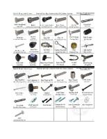
DIN/ISO- AND STANDARD PARTS
2 DIN/ISO- and standard parts (steel)
1467
T Technical information
T
For following chapters see volume II:
4
3 DIN/ISO- and standard parts (stainless steel) 5 4 DIN/ISO- and standard parts (other materials) 5 Fasteners for wood, dry wall and window construction 6 Fasteners for façade and roof construction 7 Fasteners for mechanical engineering and vehicle construction 8 Rivet technology
6
7
8
9 Procurement items 10 Assortments
9
10
T
11327921_IT_Wuerth-Ind_DiNo_Band_1_-_Englisch_Trimboxes-layer
0
1468
date+time
11327921_IT_Wuerth-Ind_DiNo_Band_1_-_Englisch_Trimboxes-layer
SC_en_band1_kt-01_s1253-1342.indd_001_040 1
11-MAY-11 05:40:57
TECHNICAL INFORMATION ON FASTENERS 1 1.1 1.2
1.3
1.4 1.5
1.6 1.7 1.8
1 Steel fasteners for the temperature range between 50°C and +150°C Materials for fasteners Mechanical properties of steel screws 1.2.1 Tensile test 1.2.2 Tensile strength Rm (MPa) 1.2.3 Apparent yielding point Re (MPa) 1.2.4 0.2% offset yield point Rp0,2 (MPa) 1.2.5 Tensile test on whole screws 1.2.6 Strength classes 1.2.7 Elongation at fracture A5 (%) 1.2.8 Hardness and hardness test methods Strength classes of screws 1.3.1 Test forces 1.3.2 Properties of screws at increased temperatures Strength classes for nuts Pairing of screws and nuts 1.5.1 Information for steel nuts 1.5.2 Stripping resistance for nuts with a nominal height ≥ 0.5 d and < 0.8 d (in accordance with DIN EN 20898, Part 2) Mechanical properties of threaded pins Marking of screws and nuts Inch thread conversion table inch/mm
3 3.1 3.2 3.3 3.4
3.5
4 4.1
4.2 4.3
2 2.1
2.2
2.3
Rust and acid-resistant fasteners Mechanical properties 2.1.1 Strength classiÀcation of stainless steel screws 2.1.2 Apparent yielding point loads for set screws 2.1.3 Reference values for tightening torques of screws Corrosion resistance of A2 and A4 2.2.1 Surface and degrading corrosion 2.2.2 Pitting 2.2.3 Contact corrosion 2.2.4 Stress corrosion cracking 2.2.5 A2 and A4 in combination with corrosive media 2.2.6 Creation of extraneous rust Marking corrosion-resistant screws and nuts
5 5.1 5.2 5.3
ISO information technical standardisation changeover to ISO Code 3.1.1 Product names and product changes DIN-ISO successor standards ISO-DIN previous standards DIN-ISO changes to widths across Áats Standard changeover DIN/ISO 3.4.1 Technical terms of delivery and basic standards 3.4.2 Small metric screws 3.4.3 Pins and screws 3.4.4 Tapping screws 3.4.5 Hexagon head screws and nuts 3.4.6 Threaded pins Dimensional changes to hexagon head screws and nuts
T
Manufacturing screws and nuts Manufacturing processes 4.1.1 Cold forming (cold extrusion) 4.1.2 Hot forming 4.1.3 Machining Thread production 4.2.1 Fibre pattern Heat treatment 4.3.1 Hardening and tempering 4.3.2 Hardening 4.3.3 Annealing 4.3.4 Case hardening 4.3.5 Stress relief annealing 4.3.6 Tempering Surface protection Corrosion Corrosion types Frequently used types of coatings for fasteners 5.3.1 Nonmetallic coatings 5.3.2 Metallic coatings 5.3.3 Other coatings
1253
1469
11327921_IT_Wuerth-Ind_DiNo_Band_1_-_Englisch_Trimboxes-layer
SC_en_band1_kt-01_s1253-1342.indd_001_040 2
5.4
T 5.5
5.6
5.7
5.8 6 6.1
6.2 6.3
6.4
6.5
Standardisation of galvanic corrosion protection systems 5.4.1 Designation system in accordance with DIN EN ISO 4042 5.4.2 Reference values for corrosion resistances in the salt spray test DIN 50021 SS (ISO 9227) 5.4.3 Designation system in accordance with DIN 50979 5.4.4 Designation of the galvanic coatings 5.4.5 Passivations 5.4.6 Sealings 5.4.7 Minimum layer thicknesses and test duration Standardisation of non-electrolytically applied corrosion protection systems 5.5.1 Zinc Áake systems 5.5.2 Standardisation of non-electrolytically applied corrosion protection systems Designations in accordance with DIN EN ISO 10683 Standardisation of the hot-dip galvanising of screws in accordance with DIN EN ISO 10684 5.6.1 Procedure and area of application 5.6.2 Thread tolerances and designation system Restriction on the use of hazardous substances 5.7.1 RoHS 5.7.2 ELV Hydrogen embrittlement Dimensioning metric screws Approximate calculation of the dimension or the strength classes of screws in accordance with VDI 2230 Choosing the tightening method and the mode of procedure Allocation of friction coefficients with reference values to different materials/surfaces and lubrication conditions in screw assemblies (in accordance with VDI 2230) Tightening torques and preload forces for set screws with metric standard thread in accordance with VDI 2230 Tightening torques and preload forces for safety and Áange screws with nuts in accordance with manufacturers information
11-MAY-11 05:40:57
6.6
Reference values for tightening torques for austenite screws in accordance with DIN EN ISO 3506 6.7 How to use the tables for preload forces and tightening torques! 6.8 Pairing different elements/contact corrosion 6.9 Static shearing forces for slotted spring pin connections 6.10 Design recommendations 6.11 Assembly 7 7.1 7.2 7.3
7.4
7.5
8 8.1 8.2 8.3
8.4
8.5
Securing elements General Causes of preload force loss Methods of functioning 7.3.1 Securing against loosening 7.3.2 Securing against unscrewing 7.3.3 Securing against loss How securing elements work 7.4.1 Ineffective securing elements 7.4.2 Loss-proof fasteners 7.4.3 Loose-proof fasteners Measures for securing screws 7.5.1 Loosening 7.5.2 Automatic unscrewing Steel structures HV joints for steel structures HV screws, nuts and washers Construction information and veriÀcations for HV joints in accordance with DIN 18800-1 and DIN EN 1993-1-8 8.3.1 HV joints in accordance with DIN 18800-1 (2008) 8.3.2 HV joints in accordance with DIN EN 1993-1-8 Assembly 8.4.1 Assembly and test in accordance with DIN 18800-7 8.4.2 Assembly in accordance with DIN EN 1090-2 Special information for using HV assemblies 1745
1254
1470
11327921_IT_Wuerth-Ind_DiNo_Band_1_-_Englisch_Trimboxes-layer
SC_en_band1_kt-01_s1253-1342.indd_001_040 3
9 9.1 9.2
9.3
11-MAY-11 05:40:57
Direct screwing into plastics and metals Direct screwing into plastics Direct screwing into metals 9.2.1 Metric thread grooving screws 9.2.2 Screw assemblies for thread-grooving screws in accordance with DIN 7500 9.2.3 Direct screwing into metals with threadgrooving screws in accordance with DIN 7500 Tapping screws 9.3.1 Tapping screw assemblies 9.3.2 Thread for tapping screws
T
10 Riveting 10.1 Rivet types 10.1.1 Solid rivets 10.1.2 Hollow rivets 10.1.3 Tubular rivets 10.1.4 Expanding rivets 10.1.5 Semi-tubular pan head rivets 10.1.6 Two-piece hollow rivet 10.1.7 Blind rivets 10.2 Instructions for use 10.2.1 Joining hard to soft materials 10.2.2 Corner clearances for connections 10.3 DeÀnitions and mechanical parameters 10.4 Using blind rivets 10.5 Rivet nuts 10.5.1 Using rivet nuts 10.5.2 Special types of rivet nuts 10.6 Rivet screws 10.7 Troubleshooting 10.7.1 Selected grip range too large 10.7.2 Grip range too small 10.7.3 Bore hole too big 10.7.4 Bore hole too small 10.8 Explanation of terms 10.8.1 Cup-type blind rivet 10.8.2 Grip range 10.8.3 Multi-range blind rivet 10.8.4 Rivet sleeve diameter 10.8.5 Rivet sleeve length 10.8.6 Closing head 10.8.7 Setting head 10.8.8 Rupture joint
1255
1471
11327921_IT_Wuerth-Ind_DiNo_Band_1_-_Englisch_Trimboxes-layer
SC_en_band1_kt-01_s1253-1342.indd_001_040 4
11-MAY-11 05:40:57
1. STEEL FASTENERS FOR THE TEMPERATURE RANGE BETWEEN 50°C AND +150°C 1.1 Materials for fasteners The material that is used is of decisive importance for the quality of the fasteners (screws, nuts and Àttings). If there are any faults in the material used, the fastener made from it can no longer satisfy the requirements made of it.
T
These standards stipulate the material that is to be used, the marking, the properties of the Ànished parts and their tests and test methods. Different materials are used for the different strength classes which are listed in the following table 1.
The most important standards for screws and nuts are: DIN EN ISO 898-1, Mechanical properties of fasteners made of carbon steel and alloy steel, Part 1: Screws DIN EN 20898 Part 2 (ISO 898 Part 2), Mechanical properties of fasteners, Part 2: Nuts
Strength class
Material and heat treatment
Chemical composition (molten mass analysis %)a C
Tempering temperature
P
S
Bb
°C
min.
max.
max.
max.
max.
min.
0.55
0.050
0.060
not stipulated
5.6c
0.13
0.55
0.050
0.060
5.8d
0.55
0.050
0.060
6.8d
0.15
0.55
0.050
0.060
Carbon steel with additives (e.g. B or Mn or Cr), hardened and tempered or
0.15e
0.40
0.025
0.025
0.003
425
Carbon steel, hardened and tempered or
0.25
0.55
0.025
0.025
Alloy steel, hardened and tempered g
0.20
0.55
0.025
0.025
Carbon steel with additives (e.g. B or Mn or Cr), hardened and tempered or
0.15e
0.40
0.025
0.025
0.003
425
Carbon steel, hardened and tempered or
0.25
0.55
0.025
0.025
Alloy steel, hardened and tempered g
0.20
0.55
0.025
0.025
Carbon steel with additives (e.g. B or Mn or Cr), hardened and tempered or
0.20e
0.55
0.025
0.025
0.003
425
Carbon steel, hardened and tempered or
0.25
0.55
0.025
0.025
Alloy steel, hardened and tempered g
0.20
0.55
0.025
0.025
4.6c, d
Carbon steel or carbon steel with additives
4.8d
8.8f
9.8f
10.9f
1256
1472
11327921_IT_Wuerth-Ind_DiNo_Band_1_-_Englisch_Trimboxes-layer
SC_en_band1_kt-01_s1253-1342.indd_001_040 5
Strength class
Material and heat treatment
11-MAY-11 05:40:57
Chemical composition (molten mass analysis %)a C min.
max.
Tempering temperature
P
S
Bb
°C
max.
max.
max.
min.
12.9f, h, i
Alloy steel, hardened and tempered g
0.30
0.50
0.025
0.025
0.003
425
12.9
Carbon steel with additives (e.g. B or Mn or Cr or molybdenum), hardened and tempered
0.28
0.50
0.025
0.025
0.003
380
a b c
d e
f
g
h i
f, h, i
In case of arbitration, the product analysis applies. The boron content may reach 0.005%, provided that the non-effective boron is controlled by additions of titanium and/or aluminium. In case of cold-formed screws in strength classes 4.6 and 5.6 heat treatment of the wire used for cold forming or the cold formed screw may be necessary to achieve the required ductility. Free-cutting steel with the following max. sulphur, phosphorous and lead shares is permissible for these strength classes: sulphur 0.34%; phosphorous 0.11%; lead 0.35%. A manganese content of not less than 0.6% for strength class 8.8 and 0.7% for strength classes 9.8 and 10.9 must be present in simple carbon steel with boron as an additive and a carbon content under 0.25% (molten mass analysis). Materials in these strength classes must be sufficiently hardenable to ensure that there is a martensite share of roughly 90% in the hardened state before tempering in the microstructure of the core in the threaded part. Alloy steel must contain at least one of the following alloying components in the given minimum amount: chromium 0.30%, nickel 0.30%, molybdenum 0.20%, vanadium 0.10%. If two, three or four elements are ascertained in combinations and have smaller alloy shares than those given above, the threshold value to be applied for the classiÀcation is 70% of the sum of the individual threshold values given above for the two, three or four elements concerned. In case of strength class 12.9/12.9 a metallographically detectable white layer enriched with phosphorous is not permissible. This must be veriÀed with a suitable test procedure. Caution is necessary when strength class 12.9/12.9 is used. The suitability of the screw manufacturer, the assembly and the operating conditions must be taken into account. Special environmental conditions may lead to stress corrosion cracking of both uncoated and coated screws.
1.2 Mechanical properties of steel screws This chapter provides a brief overview of the methods used to stipulate and determine the mechanical properties of screws. In this context, the most common parameters and rated quantities will be discussed.
T
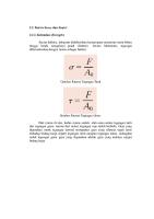
Tensile strength on fracture in thread: Rm = maximum tensile force/tension cross-section = F/As [MPa] As tension cross-section
1.2.1 Tensile test The tensile test is used to determine important parameters for screws such as tensile strength Rm, yield point Re, 0.2% offset yield point Rp0.2, and elongation at fracture A5 (%). A difference is made between tensile test with turned off specimens and tensile test on whole screws (DIN EN ISO 898 Part 1). 1.2.2 Tensile strength Rm (MPa) The tensile strength Rm indicates the tensile stress from which the screw may fracture. It results from the maximum force and the corresponding cross-section. With full strength screws the fracture may only occur in the shaft or in the thread, and not in the connection between the head and the shaft. Tensile strength on fracture in cylindrical shaft (turned off or whole screws): Rm = maximum tensile force/cross-section area = F/So [MPa]
1257
1473
11327921_IT_Wuerth-Ind_DiNo_Band_1_-_Englisch_Trimboxes-layer
SC_en_band1_kt-01_s1253-1342.indd_001_040 6
11-MAY-11 05:40:57
1.2.3 Apparent yielding point Re (MPa) Under DIN EN ISO 898 Part 1 the exact yield point can only be determined on turned off specimens. The yield point is the point to which a material, under tensile load, can be elongated without permanent plastic deformation. It represents the transition from the elastic to the plastic range. Fig. C shows the qualitative curve of a 4.6 screw (ductile steel) in the stress-strain diagram.
T
Tensile test on a turned-off screw Fig. A
Tensile test on a whole screw Fig. B
Stress-strain diagram of a screw with the strength class 4.6 (qualitative) Fig. C
1258
1474
11327921_IT_Wuerth-Ind_DiNo_Band_1_-_Englisch_Trimboxes-layer
SC_en_band1_kt-01_s1253-1342.indd_001_040 7
1.2.4 0.2% o set yield point Rp0.2 (MPa) The offset yield point Rp0.2 is determined as a so-called substitute yield point, because most hardened and tempered steels do not show a marked transition from the elastic into the plastic range. The 0.2% offset yield point Rp0.2 represents the tension at which a permanent elongation of 0.2% is achieved. Fig. D shows the qualitative tension curve in the stress-strain diagram for a 10.9 screw.
11-MAY-11 05:40:57
1.2.6 Strength classes Screws are designated with strength classes, so that it is very easy to determine the tensile strength Rm and the yield point Re (or the 0.2% offset yield point Rp0.2). Example: Screw 8.8 1. Determining Rm: the Àrst number is multiplied by 100. Rm = 8 x 100 = 800 Mpa The Àrst number indicates 1/100 of the minimum tensile strength in MPa. 2. Determining Re or Rp0.2:
T
the Àrst number is multiplied by the second and the result is multiplied by 10; the result is the yield point Re or 0.2% offset yield point Rp0.2. Re = (8 x 8) x 10 = 640 MPA.
Stress-strain diagram of a screw with strength class 10.9 (qualitative) Fig. D 1.2.5 Tensile test on whole screws Along with the tensile test on turned off specimens, a less complicated test of whole screws is also possible. In this test, the whole screw is clamped into the test device at the head and the thread. Because in this case the ratio of the length and the diameter of the specimen is not always the same, in deviation from the test for the proportional rod, this test can only be used to determine the tensile strength Rm, the extension to fracture Af and the 0.004 8 d offset yield point Rpf. 0.004 8 d offset yield point Rpf (MPa) in accordance with chapter 9.3 of ISO 898-1 2009-08.
1.2.7 Elongation at fracture A5 (%) The elongation at fracture is an important parameter for assessing the ductility of a material and is created on the load to the screw fracturing. This is determined on turned off screws with a deÀned shaft range (proportional rod) (exception: rust- and acid-resistant screws, steel group A1A5). The permanent plastic elongation is shown as a percentage and is calculated using the following equation: A5 = (LuLo)/Lo x 100% Lo DeÀned length before the tensile test L o = 5 x do Lu Length after fracture do Shaft diameter before the tensile test Example of a proportional rod
Fig. E
1259
1475
11327921_IT_Wuerth-Ind_DiNo_Band_1_-_Englisch_Trimboxes-layer
SC_en_band1_kt-01_s1253-1342.indd_001_040 8
1.2.8 Hardness and hardness test methods DeÀnition: Hardness is the resistance that a body uses to counter penetration by another, harder body. The most important hardness test methods in practice are:
T
Test method
Vickers hardness HV DIN EN ISO 6507
Brinell hardness HB DIN EN ISO 6506
Rockwell hardness HRC DIN EN ISO 6508
Specimen
Pyramid
Ball
Tube
The test using the Vickers method comprises the complete hardness range for screws.
11-MAY-11 05:40:57
Comparison of hardness data The following graph F applies for steels and corresponds to the hardness comparison tables in DIN EN ISO 18265. These should be used as a starting point, because an exact comparison of results is only possible with the same method and under the same conditions. 1.3 Strength classes of screws The mechanical and physical properties of screws and nuts are described with the help of the strength classes. This is done for screws in Table 2 below by means of nine strength classes, in which each of the properties such as tensile strength, hardness, yield point, elongation at fracture, etc., are shown.
Representation of di erent hardness scales on the Vickers scale
Legend: X Vickers hardness HV 30 Y1 Rockwell hardness Y2 Brinell hardness
1 2 3 a b
Hardness range for non-ferrous metals Hardness range for steels Hardness range for hard metals Brinell hardness, determined with steel ball (HBS) Brinell hardness, determined with hard metal tube (HBW)
Fig. F: Extract from DIN EN ISO 18265
1260
1476
11327921_IT_Wuerth-Ind_DiNo_Band_1_-_Englisch_Trimboxes-layer
SC_en_band1_kt-01_s1253-1342.indd_001_040 9
11-MAY-11 05:40:57
Mechanical and physical properties of screws Strength class No. Mechanical or physical property
4.6
4.8
5.6
5.8
6.8
8.8
9.8
10.9
d d> d 16 mma 16 mmb 16 mm 1
Tensile strength, Rm, MPa Lower yield point, ReLd, MPa
2
500
12.9/ 12.9
nom.c
400
600
800
900
1,000
1,200
min.
400
420
500
520
600
800
830
900
1,040
1,220
nom.c
240
300
min.
240
300
640
640
720
900
1,080
3
0.2% offset yield point Rp0.2, MPa
nom.c min.
640
660
720
940
1,100
4
0.0004 8 d offset yield point for whole screws Rpf, MPa
nom.c
320
400
480
min.
340e
420e
480e
5
Tension under test force, Sp , MPa
nom.
225
310
280
380
440
580
600
650
830
970
0.94
0.91
0.93
0.90
0.92
0.91
0.91
0.90
0.88
0.88
20
12
12
10
9
8
48
48
44
f
Test resistance ratio Sp,nom/ReL min or Sp,nom/Rp0,2 min or Sp,nom/Rpf min 6
Percentage elongation at fracture of a turned off specimen, A, %
min.
22
7
Percentage contraction at fracture of a turned off specimen, Z, %
min.
8
Extension to fracture of a whole screw, Af (see Annex C as well)
min.
52 0,24
0,22
0,20
155
160
190
250
255
290
320
385
250
320
335
360
380
435
238
242
276
304
366
318
342
361
414
39
9
Head impact strength
10
Vickers hardness, HV F ≥ 98 N
min.
120
max.
220g
Brinell hardness, HBW F = 30 D2
min.
114
max.
209g
Rockwell hardness, HRB
min.
67
max.
95.0g
Rockwell hardness, HRC
min.
22
23
28
32
max.
32
34
37
39
44
11 12
No fracture 130 124
147
152
181 238
304
71
79
82
89
99,5
13
Surface hardness, HV, 0.3
max.
h
h,i
h,j
14
Height of non-decarburised thread zone, E, mm
min.
1/2H1
2/3H1
3/4H1
Depth of complete decarburisation in the thread, G, mm
max.
0,015
15
Loss of hardness following re-tempering (hardening), HV
max.
20
16
Fracture torque, MB, Nm
min.
17
Notch impact energy, KVk, l, J
min.
27
m
18
Surface condition in accordance with
a b c d e f g h i j k l m n
T
nach ISO 898-7 27
27
ISO 6157-1n
27
27
ISO 6157-3
Values do not apply to steel construction screws. For steel construction screws d ≥ M12. Nominal values are stipulated only for the designation system of the strength classes. See Annex 5. If the lower yield point ReL cannot be determined, the 0.2% offset yield point Rp0.2 may be determined. The values for Rpf min are examined for strength classes 4.8, 5.8 and 6.8. The current values are shown only for the calculation of the test stress ratio. They are not test values. Test forces are stipulated in tables 5 and 7. The hardness measured at the end of a screw may not exceed max. 250 HV, 238 HB or 99.5 HRB. The surface hardness at the respective screw may not exceed 30 Vickers points of the measured core hardness, if both the surface hardness and the core hardness are determined with HV 0.3. An increase of the surface hardness to over 390 HV is not permissible. An increase of the surface hardness to over 435 HV is not permissible. The values are determined at a test temperature of 20°C, cf. 9.14. Applies for d ≥ 16 mm. Values for KV are examined. ISO 6157-3 may apply instead of ISO 6157-1 by agreement between the manufacturer and the customer.
Tab. 2: Extract from DIN EN ISO 898-1, mechanical and physical properties of screws 1261
1477
11327921_IT_Wuerth-Ind_DiNo_Band_1_-_Englisch_Trimboxes-layer
SC_en_band1_kt-01_s1253-1342.indd_001_040
11-MAY-11 05:40:57
1.3.1 Test forces In the tensile test the test force shown in tables 3 and 4 is applied axially to the screw and held for 15 s. The test is regarded as successful if the screw length after measuring coincides with the length before the test. A tolerance of ±12.5 μm applies. The following tables are an important help for the user for choosing suitable screws. ISO metric standard thread
T
Threada d
M3 M3.5 M4
Nominal tension cross-section t As, nomb, mm2 5.03 6.78 8.78
Strength class 4.6
4.8
5.6
5.8
6.8
8.8
9.8
10.9
12.9/ 12.9
Test force, Fp (As, nom × Sp), N 1,130 1,530 1,980
1,560 2,100 2,720
1,410 1,900 2,460
1,910 2,580 3,340
2,210 2,980 3,860
2,920 3,940 5,100
3,270 4,410 5,710
4,180 5,630 7,290
4,880 6,580 8,520
M5 M6 M7
14.2 20.1 28.9
3,200 4,520 6,500
4,400 6,230 8,960
3,980 5,630 8,090
5,400 7,640 11,000
6,250 8,840 12,700
8,230 11,600 16,800
9,230 13,100 18,800
11,800 16,700 24,000
13,800 19,500 28,000
M8 M10 M12
36.6 58 84.3
8,240c 13,000c 19,000
11,400 18,000 26,100
10,200c 16,200c 23,600
13,900 22,000 32,000
16,100 25,500 37,100
21,200c 33,700c 48,900d
23,800 37,700 54,800
30,400c 48,100c 70,000
35,500 56,300 81,800
43,700 59,700 73,000
50,600 66,700d 74,800 95,500 69,100 91,000d 102,000 130,000 84,500 115,000 159,000
112,000 152,000 186,000
M14 M16 M18
115 157 192
25,900 35,300 43,200
35,600 48,700 59,500
32,200 44,000 53,800
M20 M22 M24
245 303 353
55,100 68,200 79,400
76,000 93,900 109,000
68,600 84,800 98,800
93,100 108,000 147,000 115,000 133,000 182,000 134,000 155,000 212,000
203,000 252,000 293,000
238,000 294,000 342,000
M27 M30 M33
459 561 694
103,000 126,000 156,000
142,000 128,000 174,000 157,000 215,000 194,000
174,000 202,000 275,000 213,000 247,000 337,000 264,000 305,000 416,000
381,000 466,000 576,000
445,000 544,000 673,000
M36 M39
817 976
184,000 220,000
253,000 229,000 303,000 273,000
310,000 359,000 490,000 371,000 429,000 586,000
678,000 810,000
792,000 947,000
a b c d
If a thread pitch is not indicated in the thread designation, the standard thread is stipulated. See 9.1.6.1 for the calculation of As,nom. In accordance with ISO 10684:2004, Annex A, reduced values apply for screws with thread tolerance 6az in accordance with ISO 965-4 that are to be hot-galvanised. For steel construction screws 50700 N (for M12), 68800 N (for M14) and 94500 N (for M16).
Tab. 3: Extract from DIN EN ISO 898-1, Test forces for ISO metric standard thread
1262
1478
11327921_IT_Wuerth-Ind_DiNo_Band_1_-_Englisch_Trimboxes-layer
SC_en_band1_kt-01_s1253-1342.indd_001_040
11-MAY-11 05:40:57
Metric ISO Àne thread Thread dxP
Nominal Strength class tension 4.6 4.8 5.6 5.8 cross-section t As, nomb, mm2 Test force, Fp (As, nom × Sp), N
6.8
8.8
9.8
12.9/ 12.9
10.9
M8 x 1 M10 x 1.25 M10 x 1
39.2 61.2 64.5
8,820 13,800 14,500
12,200 19,000 20,000
11,000 17,100 18,100
14,900 23,300 24,500
17,200 26,900 28,400
22,700 35,500 37,400
25,500 39,800 41,900
32,500 50,800 53,500
38,000 59,400 62,700
M12 x 1.5 M12 x 1.25 M14 x 1.5
88.1 92.1 125
19,800 20,700 28,100
27,300 28,600 38,800
24,700 25,800 35,000
33,500 35,000 47,500
38,800 40,500 55,000
51,100 53,400 72,500
57,300 73,100 59,900 76,400 81,200 104,000
85,500 89,300 121,000
M16 x 1.5 M18 x 1.5 M20 x 1.5
167 216 272
37,600 48,600 61,200
51,800 67,000 84,300
46,800 60,500 76,200
63,500 73,500 96,900 82,100 95,000 130,000 103,000 120,000 163,000
109,000 139,000 179,000 226,000
162,000 210,000 264,000
M22 x 1.5 M24 x 2 M27 x 2
333 384 496
74,900 103,000 93,200 86,400 119,000 108,000 112,000 154,000 139,000
126,000 146,000 200,000 146,000 169,000 230,000 188,000 218,000 298,000
276,000 319,000 412,000
323,000 372,000 481,000
M30 x 2 M33 x 2 M36 x 3
621 761 865
140,000 192,000 174,000 171,000 236,000 213,000 195,000 268,000 242,000
236,000 273,000 373,000 289,000 335,000 457,000 329,000 381,000 519,000
515,000 632,000 718,000
602,000 738,000 839,000
M39 x 3
1,030
232,000 319,000 288,000
391,000 453,000 618,000
855,000
999,000
T
a See 9.1.6.1 for the calculation of As,nom
Tab. 4: Extract from DIN EN ISO 898-1, Test forces for ISO metric Àne thread 1.3.2 Properties of screws at increased temperatures The values shown apply only as an indication for the reduction of the yield points in screws that are tested under increased temperatures. They are not intended for the acceptance test of screws. Strength class
Temperature + 20 °C
+ 100 °C
+ 200°C
+ 250°C
+ 300°C
Lower yield point ReL or 0.2% o set yield point Rp 0.2 MPa 5.6
300
250
210
190
160
8.8
640
590
540
510
480
10.9
940
875
790
745
705
12.9
1,100
1,020
925
875
825
Tab. 5: Extract from DIN EN ISO 898-1 1999-11, hot yield strength 1.4 Strength classes for nuts With nuts, the test stress and the test forces calculated from it are usually indicated as parameters (04 to 12), because the yield point does not have to be stated. Up to the test forces shown in table 6 a tensile load on a screw is possible without problems (take note of pairing 1.5). The strength class of a nut is described through a test
stress in relation to a hardened test mandrel and divided by 100. Example: M6, test stress 600 MPa 600/100 = 6 strength class 6
1263
1479
11327921_IT_Wuerth-Ind_DiNo_Band_1_-_Englisch_Trimboxes-layer
SC_en_band1_kt-01_s1253-1342.indd_001_040
11-MAY-11 05:40:57
Test forces for ISO metric standard thread (nuts) Thread
T
Thread pitch
Nominal stressed cross section of the test mandrel As
Strength class
mm
mm2
Style 1
Style 1
M3 M3.5 M4
0.5 0.6 0.7
5.03 6.78 8.78
1,910 2,580 3,340
2,500 3,400 4,400
2,600 3,550 4,550
3,000 4,050 5,250
4,000 5,400 7,000
4,500 6,100 7,900
5,700 5,200 7,700 7,050 9,150 10,000
5,800 7,800 10,100
M5 M6 M7
0.8 1 1
14.2 20.1 28.9
5,400 7,640 11,000
7,100 10,000 14,500
8,250 11,700 16,800
9,500 13,500 19,400
12,140 17,200 24,700
13,000 18,400 26,400
14,800 16,200 20,900 22,900 30,100 32,900
16,300 23,100 33,200
M8 M10 M12
1.25 1.5 1.75
36.6 58.0 84.3
13,900 22,000 32,000
18,300 29,000 42,200
21,600 34,200 51,400
24,900 39,400 59,000
31,800 50,500 74,200
34,400 54,500 80,100
38,100 41,700 60,300 66,100 88,500 98,600
42,500 67,300 100,300
M14 M16 M18
2 2 2.5
115 157 192
43,700 59,700 73,000
70,200 80,500 101,200 57,500 109,300 95,800 109,900 138,200 78,500 149,200 96,000 97,900 121,000 138,200 176,600 170,900 176,600
120,800 134,600 164,900 183,700 203,500
136,900 186,800 230,400
M20 M22 M24
2.5 2.5 3
245 303 353
93,100 122,500 125,000 154,400 176,400 225,400 218,100 225,400 115,100 151,500 154,500 190,900 218,200 278,800 269,700 278,800 134,100 176,500 180,000 222,400 254,200 324,800 314,200 324,800
259,700 321,200 374,200
294,000 363,600 423,600
M27 M30 M33
3 3.5 3.5
459 561 694
174,400 229,500 234,100 289,200 330,550 422,300 408,500 422,300 213,200 280,500 286,100 353,400 403,900 516,100 499,300 516,100 263,700 347,000 353,900 437,200 499,700 638,500 617,700 638,500
486,500 594,700 735,600
550,800 673,200 832,800
M36 M39
4 4
817 976
310,500 408,500 416,700 514,700 588,200 751,600 727,100 751,600 866,000 370,900 488,000 497,800 614,900 702,700 897,900 868,600 897,900 1,035,000
980,400 1,171,000
04
05
4
5
6
8
9
10
12
Test force (AS × Sp), N
Style 1
Style 1
Style 2
Style 2
Style 1
Style 1
Style 2
Tab. 6: Extract from DIN EN 20898-2, Test forces for ISO metric standard thread (nuts) The test force FP is calculated as follows with the help of the test stress Sp (DIN EN 20898 Part 2) and the nominal stressed cross section As: Fp = As x Sp
nuts have to be paired in accordance with the above rule. In addition, a screw assembly of this type is fully loadable.
The nominal tension cross-section is calculated as follows:
Note: In general nuts in the higher strength class can be used instead of nuts in the lower strength class. This is advisable for a screws-nut connection with loads above the yield point or above the test stress (expansion screws).
As =
π 4
( ( d2 + d 3 2
2
where: d2 is the Áank diameter of the external thread (nominal size) d3 is the core diameter of the production proÀle of the external thread (nominal size) d 3 = d1
H 6
with d1 Core diameter of the base proÀle of the external thread H = height of the proÀle triangle of the thread 1.5 Pairing of screws and nuts: Rule: If a screw has strength class 8.8, a nut with a strength class 8 has to be chosen as well. To avoid the danger of stripping threads when tightening with modern assembly technology methods, screws and 1264
1480
11327921_IT_Wuerth-Ind_DiNo_Band_1_-_Englisch_Trimboxes-layer
SC_en_band1_kt-01_s1253-1342.indd_001_040
Pairing of screws and nuts (nominal heights Strength class of the nuts
11-MAY-11 05:40:57
0.8 D)
Appropriate screw
Nuts Style 1
Style 2
Strength class
Thread range
Thread range
4
3.6
4.6
4.8
> M16
> M16
5
3.6
4.6
4.8
≤ M16
≤ M39
5.6
5.8
≤ M39
6
6.8
≤ M39
≤ M39
8
8.8
≤ M39
≤ M39
> M16 ≤ M39
9
9.8
≤ M16
≤ M16
10
10.9
≤ M39
≤ M39
12
12.9
≤ M39
≤ M16
≤ M39
T
Tab. 7: Extract from DIN EN 20898 Part 2 1.5.1 Information for steel nuts A screw in strength class 8.8 is paired with a nut in strength class 8 or higher. Thanks to this connection, the screw can be loaded to the yield point. If nuts with a limited loadability are used for example in strength class 04, 05; nuts with hardness details 14H, 22H this is not the case. There are test forces for these nuts in accordance with DIN EN 20898-2. Strength class of Test stress the nuts of the nuts
1.5.2 Stripping resistance for nuts with a nominal height 0.5 d and < 0.8 d (in accordance with DIN EN 20898, Part 2) If nuts are paired with screws in a higher strength class, stripping of the nuts thread can be expected. The reference value show here for the stripping resistance refers to the strength class shown in the table.
Minimum stress in the screw before stripping when paired with screws in strength classes in N/mm2
N/mm2
6.8
8.8
10.9
12.9
04
380
260
300
330
350
05
500
290
370
410
480
Tab. 8: Extract from DIN EN 20898 Part 2 There is limited loadability as well for nuts in accordance with DIN 934 that are marked I8I, and I4I, I5I, I6I, I9I, I10I, I12I. When a screw in strength class 8.8 and a nut in accordance with DIN 934 (nominal height approx. 0.8 x d) are used, this connection is not to be loaded with certainty to the screws yield point. To mark and differentiate them, these nuts are marked with a bar before and after the 8 (I8I) instead of just 8.
1.6 Mechanical properties of threaded pins (in accordance with DIN EN ISO 898, Part 5) The mechanical properties apply for threaded pins and similar threaded parts not subject to tensile stress that are made of alloyed and unalloyed steel.
1265
1481
11327921_IT_Wuerth-Ind_DiNo_Band_1_-_Englisch_Trimboxes-layer
SC_en_band1_kt-01_s1253-1342.indd_001_040
Mechanical property
Strength class1) 14H
22 H
33 H
45H
Vickers hardness HV
min. max.
140 290
220 300
330 440
450 560
Brinell hardness HB, F = 30 D2
min. max.
133 276
209 285
314 418
428 532
Rockwell hardness HRB
min. max.
75 105
95
Rockwell hardness HRC
min. max.
30
33 44
45 53
320
450
580
Surface hardness HV 0.3 1)
T
11-MAY-11 05:40:57
Strength classes 14H, 22H and 33H do not apply to threaded pins with a hexagonal socket
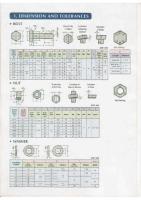
Tab. 9: Extract from EN ISO 898-5 1.7 Marking of screws and nuts Marking screws with full loadability Hexagon head screws: Marking hexagon head screws with the manufacturers mark and the strength class is prescribed for all strength classes and a nominal thread diameter of d ≥ 5 mm.
Socket head cap screws: Marking socket head cap screws with the manufacturers mark and the strength class is prescribed for strength classes ≥ 8.8 and a thread diameter of d ≥ 5 mm.
The screw must be marked at a point where its shape permits.
Fig. H: Example for the marking of socket head cap screws
Fig. G: Example for the marking of hexagon head screws
1266
1482
11327921_IT_Wuerth-Ind_DiNo_Band_1_-_Englisch_Trimboxes-layer
SC_en_band1_kt-01_s1253-1342.indd_001_040
11-MAY-11 05:40:57
Marking nuts Strength class
04
05
4
5
6
8
9
10
12
Mark
04
05
4
5
6
8
9
10
12
Tab. 10: Extract from EN 20898-2 Marking screws with reduced loadability Screws with reduced loadability have an 0 before the strength class mark, e.g. 8.8. The point between the digits may be omitted so that the variants 08.8 and 088 are possible. This marking is possible for all strength classes.
8 8
T
Fig. I: Example of marking with the code number of the strength class Marking of hexagonal nuts with the manufacturers mark and the strength class is prescribed for all strength classes and with a thread ≥ M5. Hexagonal nuts must be marked on the bearing surface or on a Áat with a recessed mark or on the chamfer with a raised mark. Raised marks may not project beyond the nuts bearing surface. As an alternative to the marking with the code number of the strength class, marking can also be done with the help of the clockwise system (for more information see DIN EN 20898 Part 2). 1.8 Inch thread conversion table inch/mm Inch
1/4
5/16
3/8
7/16
1/2
5/8
3/4
7/8
1
1.1/4
mm
6.3
7.9
9.5
11.1
12.7
15.9
19.1
22.2
25.4
31.8
Inch
1.1/2
1.3/4
2
2.1/4
2.1/2
2.3/4
3
3.1/2
4
mm
38.1
44.5
50.8
57.1
63.5
69.9
76.2
88.9
102.0
Number of threads per 1 UNC/UNF 0-inch
1/4
5/16
3/8
7/16
1/2
5/8
3/4
Thread pitch UNC
20
18
16
14
13
11
10
Thread pitch UNF
28
24
24
20
20
18
16
Tab. 11: Thread pitch UNC/UNF
1267
1483
11327921_IT_Wuerth-Ind_DiNo_Band_1_-_Englisch_Trimboxes-layer
SC_en_band1_kt-01_s1253-1342.indd_001_040
11-MAY-11 05:40:57
2. RUST AND ACID-RESISTANT FASTENERS Example: A270 A Austenite steel 2 Alloy type in group A 70 Tensile strength not less than 700 MPa, strain-hardened
2.1 Mechanical properties DIN EN ISO 3506 applies to screws and nuts made of stainless steel. There are a great number of stainless steels, which are classiÀed in the three steel groups austenite, ferrite and martensite, whereby austenite steel is the most widespread.
T
The steel groups and the strength classes are designated with a four-character sequence of letters and digits.
Steel group
Austenite
Martensitisch
Steel grade
A1 A221 A3 A423 A5
Strength classes screws, nuts type 1
50
70
80
50
70
110
50
70
80
45
60
Lower nuts
025
035
040
025
035
055 025
035
040
020
030
Soft
Coldformed
Highstrength
Soft
Hardened and tempered
Soft
Coldformed
C1
Ferrite
C4
Soft
C3
F1
Hardened Hardened and and tempered tempered
Differentiation characteristics of austenite steel grades (in accordance with ISO 3506) Steel group
Chemical composition in % (maximum values, unless other details provided) C
Si
Mn
P
S
Cr
Mo
Ni
Cu
A1
0.12
1
6.5
0.2
0.150.35
1619
0.7
510
1.752.25
A2
0.1
1
2
0.05
0.03
1520
819
4
A3
0.08
1
2
0.045
0.03
1719
912
1
A4
0.08
1
2
0.045
0.03
1618.5
23
1015
4
A5
0.08
1
2
0.045
0.03
1618.5
23
10.514
1
A3 and A5 stabilised against intercrystalline corrosion through adding titanium, niobium or tantalum.
Chemical composition of austenite steels (in accordance with ISO 3506)
1268
1484
11327921_IT_Wuerth-Ind_DiNo_Band_1_-_Englisch_Trimboxes-layer
SC_en_band1_kt-01_s1253-1342.indd_001_040
11-MAY-11 05:40:57
The most important stainless steels and their composition Material name
Material no.
C %
A1
X 8 Cr Ni S 18-9
1.4305
A2
X 5 Cr Ni 1810 X 2 Cr Ni 1811
Si %
Mn %
Cr %
Mo %
Ni %
Altri %
≤ 0.10 1.0
2.0
17.0 ÷ 19.0
8 ÷ 10
S 0.15 ÷ 0.35
1.4301
≤ 0.07 1.0
2.0
17.0 ÷ 20.0
8.5 ÷ 10
1.4306
≤ 0.03 1.0
2.0
17.0 ÷ 20.0
10 ÷ 12.5
X 8 Cr Ni Ti 19/10
1.4303
≤ 0.07 1.0
2.0
17.0 ÷ 20.0
10.5 ÷ 12
A3
X 6 Cr Ni Ti 1811
1.4541
≤ 0.10 1.0
2.0
17.0 ÷ 19.0
9.0 ÷ 11.5
Ti ≥ 5 X % C
A4
X 5 Cr Ni Mo 1712
1.4401
≤ 0.07 1.0
2.0
16.5 ÷ 18.5
2.0 ÷ 2.5
10.5 ÷ 13.5
X 2 Cr Ni Mo 1712
1.4404
≤ 0.03 1.0
2.0
16.5 ÷ 18.5
2.0 ÷ 2.5
11 ÷ 14
X 6 Cr Ni Mo Ti 1712 1.4571
≤ 0.10 1.0
2.0
16.5 ÷ 18.5
2.0 ÷ 2.5
10.5 ÷ 13.5
Ti ≥ 5 X % C
A5
Tab. 15: Common stainless steels and their chemical composition Steel grade A1 Steel grade A1 is intended in particular for metal-cutting. Because of the high sulphur content, steels of this grade have lower corrosion resistance than corresponding steels with a normal sulphur content. Steel grade A2 Grade A2 steels are the more commonly used stainless steels. They are used for kitchen equipment and for apparatus for the chemical industry. Steels of this steel grade are not suitable for use in non-oxidising acids and media containing chloride, e.g. in swimming pools and in sea water.
T
Steel grade A5 Grade A5 steels are stabilised acid-resistant steels with properties of grade A4 steels (see A3 as well). 2.1.1 Strength classiÀcation of stainless steel screws DIN EN ISO 3506 puts together the steel grades that are recommended for fasteners. Austenitic steels in grade A2 are used primarily. In contrast, in case of increased corrosion loads chromium-nickel steels from steel grade A4 are used. The mechanical strength values in Table 17 below are to be used for the construction of screw assemblies made of austenitic steel.
Steel grade A3 Grade A3 steels are stainless steels stabilised through the addition of titanium, possibly niobium, tantalum, with the properties of A2 steels (stabilised against intercrystalline corrosion, e.g. after welding). Steel grade A4 Grade A4 steels are acid-resistant steels that are molybdenum alloyed and have much better corrosion resistance. A4 steels are used in large volumes in the cellulose industry, because this steel grade was developed for boiling sulphuric acids (which is the reason for the designation acid-resistant), and are suitable to a certain extent for environments containing chloride. A4 steels are also used frequently in the food industry and in ship building.
1269
1485
11327921_IT_Wuerth-Ind_DiNo_Band_1_-_Englisch_Trimboxes-layer
SC_en_band1_kt-01_s1253-1342.indd_001_040
11-MAY-11 05:40:57
Mechanical properties of screws in the austenitic steel groups Steel group
Austenitic
1) 2) 3)
T
Steel grade
A1, A2, A3, A4 and A5
Strength class
Diameter range
Screws Tensile strength 0.2% o set yield point Rm1) MPamin. Rp 0.21) MPa min.
Elongation at fracture A2) mm min.
50
≤ M39
500
210
0.6 d
70
< M243)
700
450
0.4 d
80
< M243)
800
600
0.3 d
The tensile stress is calculated in relation to the tension cross-section (see annex A or DIN EN ISO 3506-1). According to 6.2.4, the elongation at fracture is to be determined at the respective length of the screw and not on turned off specimens. d is the nominal diameter. In case of fasteners with a nominal thread diameter d > 24 mm the mechanical properties must be agreed between the user and the manufacturer. They must be marked with the steel grade and strength class in accordance with this table.
Tab. 16: Extract from DIN EN ISO 3506-1 The yield point Rp0.2 is determined in accordance with DIN EN ISO 3506-1 in the tensile test of whole screws because the strength properties are achieved in part through cold forming. 2.1.2 Apparent yielding point loads for set screws Austenitic chromium-nickel steels cannot be hardened. A higher yield point can only be achieved through strain hardening that arises as a consequence of cold forming (e.g. round die thread rolling). Table 17 shows apparent yielding point loads for set screws in accordance with DIN EN ISO 3506. Nominal diameter
Apparent yielding point loads for austenitic steels in accordance with DIN EN ISO 3506 A2 and A4 in N
Strength class
50
70
M5
2,980
6,390
M6
4,220
9,045
M8
7,685
16,470
M10
12,180
26,100
M12
17,700
37,935
M16
32,970
70,650
M20
51,450
110,250
M24
74,130
88,250
M27
96,390
114,750
M30
117,810
140,250
2.1.3 Reference values for tightening torques for screws, cf. chapter 6.6 2.2 Corrosion resistance of A2 and A4 Stainless steels and acid-resistant steels such as A2 and A4 come in the category of active corrosion protection. Stainless steels contain at least 16% chromium (Cr) and are resistant to aggressive oxidising media. Higher Cr contents and additional alloy components, such as nickel (Ni), molybdenum (Mo), titanium (Ti) or niobium (Nb), improve the corrosion resistance. These additives also inÁuence the mechanical properties. Other alloy components are added only to improve the mechanical properties, e.g. nitrogen (N), or the machining capability, e.g. sulphur (S). Fasteners made of austenitic steels are generally not magnetisable, but a certain amount of magnetisability may be present after the cold forming. However, this does not affect the corrosion resistance. Magnetisation through strain hardening can go so far that the steel part sticks to a magnet. Under the effect of oxygen stainless steel forms a stable oxide layer (passive layer). This passive layer protects the metal from corrosion.
Tab. 17: Apparent yielding point loads for set screws in accordance with DIN EN ISO 3506
1270
1486
11327921_IT_Wuerth-Ind_DiNo_Band_1_-_Englisch_Trimboxes-layer
SC_en_band1_kt-01_s1253-1342.indd_001_040
It should be noted that in practice there are a number of different types of corrosion. The more frequent types of corrosion involving stainless steel are shown below and in the following Fig. J as examples:
11-MAY-11 05:40:57
be the starting point for pitting. For this reason, residues and deposits must be cleaned regularly from all fasteners. Austenitic steels such as A2 and A4 are more resistant to pitting than ferrite chromium steels. ClassiÀcation of the degree of resistance into di erent groups Degree of resistance
Assessment
Weight loss in g/m2h
A
Fully resistant
< 0.1
B
Practically resistant
0.11.0
C
Less resistant
1.010
D
Not resistant
> 10
T
Tab. 22 a Surface degrading corrosion, pitting b Contact corrosion c Stress corrosion cracking d Mechanical effects Fig. K: The most frequent corrosion types with screw assemblies 2.2.1 Surface and degrading corrosion With uniform surface corrosion, also known as degrading corrosion, the surface is degraded evenly. This type of corrosion can be prevented through a careful selection of the material. On the basis of laboratory experiments manufacturers have published resistance tables that provide information on the behaviour of the steel grades at different temperatures and concentrations in the individual media (see chapter 2.2.5). 2.2.2 Pitting Pitting is seen through surface corrosion degrading with the additional formation of cavities and holes. The passive layer is penetrated locally here. In case of stainless steel in contact with active media containing chloride there is also pitting by itself with pinhole notches in the material. Deposits and rust can also
2.2.3 Contact corrosion Contact corrosion occurs when two components with different compositions are in metallic contact with each other and there is moisture in the form of an electrolyte. The baser element is attacked and destroyed. The following points should be observed to prevent contact corrosion: Insulating the metals at the contact point, e.g. through rubber, plastics or coatings, so that a contact current cannot Áow. Where possible, avoid unequal material pairings. As an example, screws, nuts and washers should be matched to the connecting components. Make sure that the connection is not in contact with electrolytic active means. cf. chapter 6.8 as well 2.2.4 Stress corrosion cracking This type of corrosion usually occurs in components used in industrial atmospheres that are under heavy mechanical tensile and bending loads. Internal stresses created by welding can also lead to stress corrosion cracking. Austenite steels in atmospheres containing chloride are particularly sensitive to stress corrosion cracking. The inÁuence of the temperature is considerable here. The critical temperature is 50°C.
1271
1487
11327921_IT_Wuerth-Ind_DiNo_Band_1_-_Englisch_Trimboxes-layer
SC_en_band1_kt-01_s1253-1342.indd_001_040
11-MAY-11 05:40:57
2.2.5 A2 and A4 in combination with corrosive media The following table provides an overview of the resistance of A2 and A4 in combination with various corrosive media. The values shown are intended only as reference points but still provide good possibilities for comparisons.
Overview of the chemical resistance of A2 and A4 screws
T
Corrosive agent
Concentration
Temperature in °C
Degree of resistance Degree of resistance A2 A4
Acetic acid
10%
20 boiling
A A
A A
Acetone
all
all
A
A
Ammoniac
all
20 boiling
A A
A A
Beer
all
A
A
Benzene, all types
all
A
A
Benzoic acid
all
all
A
A
Benzol
all
A
A
Blood
20
A
A
Bonderising solution
98
A
A
Carbon dioxide
A
A
Chloride: dry gas, damp gas
20 all
A D
A D
Chloroform
all
all
A
A
20 boiling 20 boiling
A C B D
A B B D
all 20 boiling
A A C
A A B A
Chromic acid
10% pure 50% pure
Citric acid
to 10% 50%
Copper acetate
all
A
Copper nitrate
A
A
Copper sulphate
all
all
A
A
Developer (photogr.)
20
A
A
Ethyl alcohol
all
20
A
A
Ethyl ether
all
A
A
Fatty acid
technical
150 180 200235
A B C
A A A
Formic acid
10%
20 boiling
A B
A A
Fruit juices
all
A
A
Glycerine
conc.
all
A
A
Hydrochloric acid
0.2%
20 50 20 50 20
B C D D D
B B D D D
2% to 10%
1272
1488
11327921_IT_Wuerth-Ind_DiNo_Band_1_-_Englisch_Trimboxes-layer
SC_en_band1_kt-01_s1253-1342.indd_001_040
Corrosive agent
Concentration
11-MAY-11 05:40:57
Temperature in °C
Degree of resistance Degree of resistance A2 A4
Hydrocyanic acid
20
A
A
Industrial air
A
A
1.5% 10%
all 20 boiling
A A C
A A A
Lactic acid Lemon juice
20
A
A
Magnesium sulphate
approx. 26%
all
A
A
Mercury
to 50
A
A
Mercury nitrate
all
A
A
Methyl alcohol
all
all
A
A
Milk of lime
all
A
A
Nitric acid
to 40% 50%
all 20 boiling 20 boiling
A A B A C
A A B A C
90% Oils (mineral and vegetable)
all
A
A
Oxalic acid
10%
20 boiling boiling
B C D
A C C
Petroleum
all
A
A
Phenol
pure
boiling
B
A
Phosphoric acid
10% 50%
boiling 20 boiling 20 boiling 20 boiling
A A C B D B D
A A B A C A D
Potassium permanganate 10%
all
A
A
Salicylic acid
20
A
A
Seawater
20
A
A
Sodium carbonate
cold saturated
all
A
A
Sodium hydroxide
20%
20 boiling 120
A B C
A B C
Sodium nitrate
all
A
A
Sodium perchlorate
10%
all
A
A
Sugar solution
all
A
A
Sulphur dioxide
100500 900
C D
A C
Sulphuric acid. 1%
to 70%
B boiling to 70 boiling 20 > 70 20 70 all
A B B C B B C C D
B A C A B B C D
50%
80% conc.
50%
2.5% 5% 10% 60% Sulphurous acid
aqueous solution
20
A
A
Tannic acid
all
all
A
A
T
1273
1489
11327921_IT_Wuerth-Ind_DiNo_Band_1_-_Englisch_Trimboxes-layer
SC_en_band1_kt-01_s1253-1342.indd_001_040
Corrosive agent
11-MAY-11 05:40:57
Concentration
Temperature in °C
Degree of resistance Degree of resistance A2 A4
Tar
hot
A
A
Tartaric acid
to 10% over 100% to 50% 75%
20 boiling 20 boiling boiling
A B A C C
A A A C C
20 and hot
A
A
Wine
2.2.6 Creation of extraneous rust Extraneous rust consists of adherent particles of a carbon steel (normal steel) on the stainless steel surface that turn into rust through the effect of oxygen. If these places are not cleaned and removed, the rust can cause electrochemical pitting corrosion even in stainless steel.
T
Extraneous rust can be caused by: Contact of objects that rust with a stainless steel surface. Flying sparks during work with a right angle grinder, or grinding dust. or during welding work. Water containing rust dripping onto a stainless steel surface. Use of tools that were previously used to work on carbon steel.
1274
1490
11327921_IT_Wuerth-Ind_DiNo_Band_1_-_Englisch_Trimboxes-layer
SC_en_band1_kt-01_s1253-1342.indd_001_040
11-MAY-11 05:40:57
Origin mark XYZ XYZ
A2-70
A2-70 XYZ
A2-70
Steel group
Strength class
A4
Alternative marking for socket head cap screws XYZ
T
A2-70 XYZ
Marking of screws that do not satisfy the requirements for tensile or torsion strength because of their geometry, e.g. low cylinder heads
A2
Fig. L: Extract from DIN EN ISO 3506-1 2.3 Marking corrosion-resistant screws and nuts The marking of corrosion-resistant screws and nuts must contain the steel group, the strength class and the manufacturers mark. Marking screws in accordance with DIN EN ISO 3506-1 Hexagon head screws and socket head cap screws from nominal diameter M5 must be clearly marked in accordance with the classiÀcation system. Where possible, the marking should be on the screw head.
Marking nuts in accordance with DIN EN ISO 3506-2 Nuts with a nominal thread diameter from 5 mm must be clearly marked in accordance with the classiÀcation system. Marking on a single Áat is permissible and may only be recessed. Marking on the Áats is also permissible as an option.
XYZ XYZ
A2-50 Strength class only with low-strength nuts (see chapter 3.2.3)
Fig. M: Extract from DIN EN ISO 3506-2
1275
1491
11327921_IT_Wuerth-Ind_DiNo_Band_1_-_Englisch_Trimboxes-layer
SC_en_band1_kt-01_s1253-1342.indd_001_040
11-MAY-11 05:40:57
3. ISO INFORMATION ON TECHNICAL STANDARDISATION CHANGEOVER TO ISO
T
3.1 Code Technical standardisation is work of harmonisation in the technical Àeld that is carried out jointly by all interested parties. Its aim is to stipulate, arrange and harmonise terms, products, procedures, etc., in the area of engineering. In this way, optimum solutions are found for all types of constructions, for example, whereby ordering the necessary components is considerably simpliÀed.
a closer look reveals that this is not the case. Many DIN standards were the foundation for ISO standards. The old DIN standards were changed into new ISO standards.
This work of harmonisation in Germany was previously carried out by the Deutsches Institut für Normung e.V. (DIN) on the national level. In addition, there are European standards (EN standards), and on an international level there are the ISO standards, which are issued by the International Organisation for Standardisation.
In many cases, a changeover from DIN to ISO is, strictly speaking, not correct, because in the past many DIN standards had already been taken over by ISO standards. During the harmonisation of the individual standards codes some titles are in fact being changed, but there are not many changes to the products themselves. For an interim period the number 20000 was added to the ISO number on the takeover of ISO standards into the European code (EN) (e.g. DIN EN ISO 24034). However, this naming system was abandoned some years ago and replaced by the now common form DIN EN ISO
.
National standards (DIN) are being or have already been largely replaced by international/European standards. There will be DIN standards only for products for which there are no ISO or EN standards. International standards (ISO). According to the task and goal of the ISO, which was established in 1946, these are intended to serve the global harmonisation of technical rules, and thus to simplify the exchange of goods and to break down barriers to trade. European standards (EN) aim at harmonising technical regulations and statutes in the internal European market, which was realised on 1.1.1995 (EU/EEC). In principle, existing ISO standards are to be taken over as far as possible unchanged as EN standards. The difference between ISO and EN standards is that, according to a decision of the European Council, EN standards are to be transposed and introduced without delay and without amendment as national standards in the Member States and the corresponding national standards are to be withdrawn in the same step. 3.1.1 Product names and product changes In many cases the introduction of the European standards is described as intransparent or even chaotic. However,
If an ISO standard is taken over into national standards codes without change, the national standard is given the same title as the corresponding ISO standard. An ISO nut is thus known as an ISO 4032-M12-8 all over the world.
It is certain that the changes to names are very annoying with regard to production documents or order data, because these have to be changed in the short or long term. But we have to be clear about one thing: the sooner we realise conformity to European standards, the sooner we will proÀt from overcoming barriers to trade or procurement within Europe. As already stated, the contents of many DIN standards already conform to the ISO standard, because they were introduced at a time at which the changeover to ISO was not yet current. Following Europeanisation there are absolutely no changes to what is certainly the most important standard for screws and nuts, ISO 898-1 Mechanical properties of fasteners, because this standard was taken over into the German standards code from the start without any changes to the contents.
1276
1492
11327921_IT_Wuerth-Ind_DiNo_Band_1_-_Englisch_Trimboxes-layer
SC_en_band1_kt-01_s1253-1342.indd_001_040
One of the most signiÀcant product changes on the harmonisation of the codes was without doubt the change of the width across Áats of all hexagonal products. Screws and nuts with dimensions M10, M12 and M14 are affected (here the width across Áats is reduced by 1 mm) and M22 (width across the Áats is 2 mm larger). Apart from these four dimensions, all other screw dimensions are already perfectly identical to ISO. This means, for example, that a DIN 933 M16 x 50-8.8 is dimensionally, and with regard to the technical properties, completely identical to ISO 4017 M16 x 50-8.8. All that is 3.2 DIN-ISO successor standards DIN
ISO
DIN
ISO
11-MAY-11 05:40:57
necessary here is a change to the name in the production documents or order Àles. In contrast, following more recent technical Àndings the ISO has changed the height of hexagonal nuts because it was recognised that the stripping resistance can no longer be guaranteed, particularly when modern tightening methods are used. In this case, the connection would no longer be safe against failure. For this reason alone the use of nuts in accordance with ISO standards is highly recommended.
T
ISO-DIN previous standards ISO DIN
ISO
ISO
1
2339
931
4014
6914
7412
1051
7
2338
933
4017
6915
7414
1207
84
1207
934
4032
6916
7416
85
1580
934
8673
6921
94
1234
960
8765
6923
125
7089
961
8676
125
7090
963
126
7091
964
417
7435
427
2342
433
DIN 660/661
ISO
DIN
ISO
DIN
4036
439
8673
84
4161
6923
8673
934 971
1234
94
4762
912
8674
971-2
8102
1479
7976
4766
551
8676
961
4161
1481
7971
7040
982
8677
603
6924
7040
1482
7972
7040
6924
8733 7979
2009
6925
7042
1483
7973
7042
980
8734 6325
2010
7343
8750
1580
85
7042
6925
8735 7979
965
7046
7343
8751
2009
963
7045
7985
8736 7978
966
7047
7344
8748
2010
964
7046
965
8737 7977
7092
971-1
8673
7346 13337
2338
7
7047
966
8738 1440
438
7436
971-2
8674
7971
1481
2339
1
7049
7981
8740 1473
439
4035
980
7042
7972
1482
2341
1434
7050
7982
8741 1474
439
4036
980
10513
7973
1483
2342
427
7051
7983
8742 1475
440
7094
982
7040
7976
1479
2936
911
7072
11024
8744 1471
551
4766
982
10512
7977
8737
4014
931
7089
125
8745 1472
553
7434
985
10511
7978
8736
4016
601
7090
125
8746 1476
555
4034
1440
8738
7979
8733
4017
933
7091
126
8747 1477
558
4018
1444
2341
7979
8735
4018
558
7092
433
8748 7344
601
4016
1471
8744
7981
7049
4026
913
7093
9021
13337 7346
603
8677
1472
8745
7982
7050
4027
914
7094
440
8750 7343
660
1051
1473
8740
7983
7051
4028
915
7412
6914
8751 7343
661
1051
1474
8741
7985
7045
4029
916
7414
6915
8752 1481
911
2936
1475
8742
7991 10642
4032
934
7416
6916
8765
912
4762
1476
8746
9021
7093
4034
555
7434
553
10642 7991
913
4026
1477
8747
11024
7072
4035
439
7435
417
10511
914
4027
1481
8752
7436
438
10512
982
915
4028
6325
8734
8102
6921
10513
980
916
4029
960 985
1277
1493
11327921_IT_Wuerth-Ind_DiNo_Band_1_-_Englisch_Trimboxes-layer
SC_en_band1_kt-01_s1253-1342.indd_001_040
11-MAY-11 05:40:57
3.3 DIN-ISO changes to widths across Áats
T
Hexagonal widths across Áats
DIN
ISO
M10
17 mm
16 mm
M12
19 mm
18 mm
M14
22 mm
21 mm
M22
32 mm
34 mm
3.4 Standard changeover DIN/ISO, general changes, classiÀed in accordance with special Àelds. Currently valid standards collections 3.4.1 Technical terms of delivery and basic standards DIN (old)
ISO
DIN (new) or DIN EN
Title
Changes
267 Part 20
DIN EN ISO 6157-2
Fasteners, surface discontinuities, nuts
Nothing noteworthy
267 Part 21
DIN EN ISO 10484
Widening test on nuts
Nothing noteworthy
DIN ISO 225
225
DIN EN 20225
Fasteners; bolts, screws, studs and nuts; symbols and designations of dimensioning (ISO 225:1991)
Nothing noteworthy
DIN ISO 273
273
DIN EN 20273
Mech. fasteners; clearance holes for bolts and screws (ISO 273: 1991)
Nothing noteworthy
DIN ISO 898 Part 1
898-1
DIN EN ISO 898 Part 1
Mech. properties of fasteners made of carbon steel and alloy steel (ISO 898-1: 1988)
Nothing noteworthy
267 Part 4
898-2
DIN EN 20898-2
Mech. properties of fasteners, part 2; nuts with speciÀed proof load (ISO 898-2: 1992)
Nothing noteworthy
DIN ISO 898 Part 6
898-6
DIN EN ISO 898 Part 6
Mech. properties of fasteners, part 6; nuts with speciÀed proof load values, Àne thread (ISO 898-6: 1988)
Nothing noteworthy
267 Part 19
6157-1
DIN EN 26157 Part 1
Fasteners -- Surface discontinuities -- Part 1: Bolts, screws and studs for general requirements (ISO 6157-1: 1988)
Nothing noteworthy
267 Part 19
6157-3
DIN EN 26157 Part 3
Nothing noteworthy Fasteners -- Surface discontinuities -- Part 3: Bolts, screws and studs for special requirements (ISO 6157-3: 1988)
DIN ISO 7721
7721
DIN EN 27721
Countersunk head screws -- Head conÀguration Nothing noteworthy and gauging (ISO 7721: 1983)
267 Part 9
DIN ISO 4042
Fasteners -- Electroplated coatings
Nothing noteworthy
267 Part 1
DIN ISO 8992
Fasteners -- General requirements for bolts, screws, studs and nuts
Nothing noteworthy
267 Part 5
DIN EN ISO 3269
Fasteners acceptance inspection
Nothing noteworthy
267 Part 11
DIN EN ISO 3506, Part 1, 2, 3
Mechanical properties of corrosion-resistant steel fasteners technical terms of delivery
Nothing noteworthy
267 Part 12
DIN EN ISO 2702
Heat-treated steel tapping screws mechanical Nothing noteworthy properties
267 Part 18
8839
DIN EN 28839
Mechanical properties of fasteners; nonferrous metal bolts, screws, studs and nuts (ISO 8839: 1986)
Nothing noteworthy
1278
1494
11327921_IT_Wuerth-Ind_DiNo_Band_1_-_Englisch_Trimboxes-layer
SC_en_band1_kt-01_s1253-1342.indd_001_040
11-MAY-11 05:40:57
3.4.2 Small metric screws DIN (old)
ISO
DIN (new) or DIN EN
Title
Changes
84
1207
DIN EN 21207
Slotted cheese head screws -- product grade A (ISO 1207: 1992)
Head height and diameter in places
85
1580
DIN EN 21580
Flat-headed screws with slot; product grade A
Head height and diameter in places
963
2009
DIN EN 22009
Countersunk screws with slot, shape A
Head height and diameter in places
964
2010
DIN EN 22010
Countersunk oval head screws with slot, shape A
Head height and diameter in places
965
7046-1
DIN EN 27046-1
Countersunk screws with cross recess (common head): product class A, strength class 4.8
Head height and diameter in places
965
7046-2
DIN EN 27046-2
Countersunk screws with cross recess (common head): product grade A, strength class 4.8
Head height and diameter in places
966
7047
DIN EN 27047
Countersunk oval head screws with cross recess Head height and (common head): product grade A diameter in places
7985
7045
DIN EN 27045
Flat-headed screws with cross recess; product grade A
Head height and diameter in places
T
3.4.3 Pins and screws DIN (old)
ISO
DIN (new) or DIN EN
Title
Changes
1
2339
DIN EN 22339
Taper pins; unhardened (ISO 2339:1986)
Length I incl. round ends
7
2338
DIN EN 22338
Parallel pins, of unhardened steel and austenitic Length I incl. round stainless steel (ISO 2338:1986) ends
1440
8738
DIN EN 28738
Plain washers for clevis pins -- Product grade A (ISO 8738: 1986)
1443
2340
DIN EN 22340
Clevis pins without head (ISO 2340:1986)
Nothing noteworthy
1444
2341
DIN EN 22341
Clevis pins with head (ISO 2341:1986)
Nothing noteworthy
1470
8739
DIN EN 8739
Grooved pins, full length parallel grooved pins with pilot (ISO 8739:1997)
Nothing noteworthy
1471
8744
DIN EN 8744
Grooved pins -- Full-length taper grooved (ISO 8744:1997)
Nothing noteworthy
1472
8745
DIN EN 8745
Grooved pins -- Half length taper grooved (ISO 8745:1997)
Nothing noteworthy
1473
8740
DIN EN 8740
Gooved pins -- Full-length parallel grooved, with Nothing noteworthy chamfer (ISO 8740:1997)
1474
8741
DIN EN 8741
Grooved pins -- Half-length reverse-taper grooved (ISO 8741:1997)
Nothing noteworthy
1475
8742
DIN EN 8742
Grooved pins - one-third-length centre grooved (ISO 8742:1997)
Increased shearing forces
1476
8746
DIN EN 8746
Grooved pins with round head (ISO 8746:1997)
Nothing noteworthy
1477
8747
DIN EN 8747
Grooved pins with countersunk head (ISO 8747:1997)
Nothing noteworthy
1481
8752
DIN EN 8752
Spring-type straight pins -- Slotted, heavy duty (ISO 8752:1997)
Bevel angle cancelled
6325
8734
DIN EN 8734
Parallel pins, of hardened steel and martensitic stainless steel (Dowel pins) (ISO 8734:1997)
Shape A/B cancelled
Outer diameter in places
1279
1495
11327921_IT_Wuerth-Ind_DiNo_Band_1_-_Englisch_Trimboxes-layer
SC_en_band1_kt-01_s1253-1342.indd_001_040
T
11-MAY-11 05:40:57
DIN (old)
ISO
DIN (new) or DIN EN
Title
Changes
7977
8737
DIN EN 28737
Tapered pins with external thread; unhardened (ISO 8737:1986)
Nothing noteworthy
7978
8736
DIN EN 28736
Tapered pins with internal thread; unhardened (ISO 8736:1986)
Nothing noteworthy
7979
8733
DIN EN 8733
Parallel pins with internal thread, of unhardened steel and austenitic stainless steel (ISO 8733:1997)
Nothing noteworthy
7979
8735
DIN EN 8735
Parallel pins with internal thread, of hardened steel and martensitic stainless steel (ISO 8735:1997)
Nothing noteworthy
3.4.4 Tapping screws DIN (old)
ISO
DIN (new) or DIN EN
Title
Changes
7971
1481
DIN ISO 1481
Slotted pan head tapping screws (ISO 1481: 1983)
Head height and diameter in places
7972
1482
DIN ISO 1482
Slotted countersunk (Áat) head tapping screws (common head style)
Head height and diameter in places
7973
1483
DIN ISO 1483
Slotted raised countersunk (oval) head tapping screws (common head style)
Head height and diameter in places
7976
1479
DIN ISO 1479
Hexagon head tapping screws
Head height in places
7981
7049
DIN ISO 7049
Cross recessed pan head tapping screws
Head height and diameter in places
7982
7050
DIN ISO 7050
Cross recessed countersunk (Áat) head tapping Head height and screws (common head style diameter in places
7983
7051
DIN ISO 7051
Cross recessed raised countersunk (oval) head tapping screws
Head height and diameter in places
3.4.5 Hexagon head screws and nuts DIN (old)
ISO
DIN (new) or DIN EN
Title
Changes
439 T1
4036
DIN EN 24036
Hexagon thin nuts, unchamfered (ISO 4036: 1979)
4 widths across Áats
439 T2
4035
DIN EN 24035
Hexagon thin nuts, unchamfered (ISO 4035: 1986)
4 widths across Áats
555
4034
DIN EN 24034
Hexagon nuts, product grade C
Nut height and 4 widths across Áats
558
4018
DIN EN 24018
Hexagon head screws, product grade C
4 widths across Áats
601
4016
DIN EN 24016
Hexagon head bolts, product grade C, DIN 555
4 widths across Áats
931
4014
DIN EN 24014
Hexagon head bolt with shank
4 widths across Áats
933
4017
DIN EN 24017
Hexagon head screw
4 widths across Áats
934 ISO type 1
4032
DIN EN 24032
Hexagonal nuts, style 1
Nut height and 4 widths across Áats
934 ISO type 1
8673
DIN EN 28673
Hexagon nuts, style 1, with metric Àne pitch thread
Nut height and 4 widths across Áats
960
8765
DIN EN 28765
Hexagon head bolts with shaft and metric Àne pitch thread
4 widths across Áats
961
8676
DIN EN 28676
Hexagon head screws 10.9, thread to head
4 widths across Áats
1280
1496
11327921_IT_Wuerth-Ind_DiNo_Band_1_-_Englisch_Trimboxes-layer
SC_en_band1_kt-01_s1253-1342.indd_001_040
11-MAY-11 05:40:57
3.4.6 Threaded pins DIN (old)
ISO
DIN (new) or DIN EN
Title
Changes
417
7435
DIN EN 27435
Slotted set screws with long dog point (ISO 7431: 1983)
Head height and diameter in places
438
7436
DIN EN 27436
Slotted set screws with cup point (ISO 7436: 1983)
Head height and diameter in places
551
4766
DIN EN 24766
Slotted set screws with Áat point (ISO 4766: 1983)
Head height and diameter in places
553
7434
DIN EN 27434
Slotted set screws with cone point (ISO 7431: 1983)
Head height and diameter in places
913
4026
DIN 913
Socket set screws with Áat point
Head height and diameter in places
914
4027
DIN 914
Slotted set screws with cone point
Head height and diameter in places
915
4028
DIN 915
Slotted set screws with dog point
Head height and diameter in places
916
4029
DIN 916
Slotted set screws with cup point
Head height and diameter in places
T
3.5 Dimensional changes to hexagonal screws and nuts Nominal size d
Width across Áat s
Nut height m min. max.
Sizes to be avoided
DIN
ISO
DIN 555
ISO 4034 ISO type 1
DIN 934
ISO 4032 (RG) 8673 (FG) ISO type 1
M1
2.5
0.550.8
0.550.8
M1,2
3
0.751
M1,4
3
0.951.2
M1,6
3.2
1.051.3
1.051.3
M2
4
1.351.6
1.351.6
M2,5
5
1.752
1.752
M3
5.5
2.152.4
2.152.4 2.552.8
(M3,5)
6
2.552.8
M4
7
2.93.2
2.93.2
M5
8
3.44.6
4.95.6
3.74
4.44.7 4.95.2
M6
10
(M7)
11
M8
13
M10
17
16
7.258.75
89.5
7.648
8.048.4
M12
19
18
9.2510.75
10.412.2
9.6410
10.3710.8
21
4.45.6
4.66.1
4.75
5.25.5
5.757.25
6.47.9
6.146.5
6.446.8
(M14)
22
12.113.9
10.311
12.112.8
M16
24
12.113.1
14.115.9
12.313
14.114.8 15.115.8
(M18)
27
15.116.9
14.315
M20
30
15.116.9
16.919
14.916
16.918
(M22)
32
17.118.9
18.120.2
16.918
18.119.4
34
M24
36
17.9520.05
20.222.3
17.719
20.221.5
(M27)
41
20.9523.05
22.624.7
20.722
22.523.8
M30
46
22.9525.05
24.326.4
22.724
24.325.6
1281
1497
11327921_IT_Wuerth-Ind_DiNo_Band_1_-_Englisch_Trimboxes-layer
SC_en_band1_kt-01_s1253-1342.indd_001_040
T
11-MAY-11 05:40:57
Nominal size d
Width across Áat s
Nut height m min. max.
(M33)
50
24.9527.05
27.429.5
24.726
M36
55
27.9530.05
29.431.9
27.429
29.431
(M39)
60
29.7532.25
31.834.3
29.431
31.833.4
27.428.7
M42
65
32.7535.25
32.434.9
32.434
32.434
(M45)
70
34.7537.25
34.436.9
34.436
34.436
M48
75
36.7539.25
36.438.9
36.438
36.438
(M52)
80
40.7543.25
40.442.9
40.442
40.442
M56
85
43.7546.25
43.445.9
43.445
43.445
(M60)
90
46.7549.25
46.448.9
46.448
46.448
M64
95
49.552.5
49.452.4
49.151
49.151
>M64
/
Nut height factor m/d approx.
to M100*6
to M100*6
≤ M4
0.8
M5M39
0.8
0.831.12
≥ M42 Product class Thread tolerance Strength class Steel
Core range ~M5-39 >M39
Mechanical properties according to standard
0.8 0.840.93
~0.8
0.8
C (average)
≤ M16 = A (average) >M16 = B (average roughness)
7H
6H
5 M16 < d ≤ M39 = 4.5
6.8,10 (ISO 8673 = strength class 10 ≤ M16)
Following agreement
Following agreement
DIN 267 Part 4
DIN 267 Part 4
ISO 898 Part 2 (ST) d ≤ M39
ISO 898 Part 2 (ST) Part 6 (FT)
ST standard thread, FT Àne thread
1282
1498
11327921_IT_Wuerth-Ind_DiNo_Band_1_-_Englisch_Trimboxes-layer
SC_en_band1_kt-01_s1253-1342.indd_001_040
11-MAY-11 05:40:57
4. MANUFACTURING SCREWS AND NUTS 4.1 Manufacturing processes In principle, the following manufacturing processes are differentiated: On the one hand there is forming without cutting and on the other, machining. With forming without cutting there is a further differentiation between cold and hot forming. The following diagram is intended to make the production processes clearer:
(wire). Screw manufacturers usually receive the wire coiled on rolls that often weigh over 1000 kg. The wire is normally phosphate treated to enable the wire to be worked perfectly and to minimise tool wear. The designer of a screw or a fastener tries during development to harmonise the advantages and disadvantages of the different materials with the requirements speciÀed for the fastener. With the materials differences are made, along with corrosion-resistant steels, between unalloyed and alloyed steels. For example, if increased strengths are required, it is absolutely essential to subject the parts after pressing to a heat treatment process in order to be able to inÁuence the mechanical properties speciÀcally.
T
Diagram of the stages for a hexagon head screw
Fig. N: Overview of the various production processes 4.1.1 Cold forming (cold extrusion) In modern fastening technology the majority of fasteners are made using the cold forming procedure. In this procedure, the fastener is formed, usually in multistage processes, by pressure forging, cold extrusion and reducing, or a combination of these procedures. The term solid or cold forming was coined for this type of production. This procedure is usually used for large quantities, because, from an economic aspect, it is the most rational method.
Wire Descaling Intermediate section upsetting
Finishing
Calibrating Round die thread rolling
Nuts are usually produced with the cold or hot forming procedure as well. The choice of one or the other procedure depends on the one hand on the size and on the other on the required quantities.
The choice of the suitable forming machine depends on the size of the fastener and on the degree of forming. The greater the degree of forming, the more forming stages are required. Sharp-edged transitions or thin proÀles are unfavourable for cold forming and lead to increased tool wear. A decisive role for the quality of the Ànal product is played by the choice and the quality of the input material
1283
1499
11327921_IT_Wuerth-Ind_DiNo_Band_1_-_Englisch_Trimboxes-layer
SC_en_band1_kt-01_s1253-1342.indd_001_040
Diagram of the stages for a hexagonal nut
T
Advantages of cold forming: Optimal use of material Very high output High dimensional accuracy and surface quality Increase of strength properties through strain hardening Run of the chamfers in press parts in accordance with the load 4.1.2 Hot forming This production method is used mainly to manufacture large diameters starting with approx. M27, and longer pieces starting from approx. 300 mm. In addition, parts are possible that cannot be produced using cold forming because of the very small volumes, or because of a very high degree of forming. With this procedure, the input material (usually bars) is heated wholly or partially to forging temperature. This heating up enables even complicated geometries or very high degrees of forming to be realised. A typical feature for a hot-formed component is the raw surface structure. Strain hardening is not carried out during hot forming!
11-MAY-11 05:40:57
During turning, the required contour of the component is cut from the input material using a turning tool. The diameter of the input material depends on the largest diameter of the component. Usually, bars with a length of up to 6 m are used. In contrast to cold or hot forming, the chamfer course of the input material is destroyed. This production procedure is used either if the production run is not very large or if the part geometry cannot be complied with in cold or hot forming procedures because of sharp edges, small radiuses or even nominal sizes. Surface roughnesses of Ra 0.4 or Rz 1.7 can be achieved with this production procedure without any problems. In the case of large production runs the blanks are often produced with the cold extrusion method and are then machined. 4.2 Thread production Where screws are mass-produced, the thread is usually formed or rolled. In this procedure, the screw is rolled between two rolling dies (Áat dies), one of which is Àxed and the other running, and this creates the thread (see the diagram). With this type of thread production it is possible to Àt several hundred screws per minute with a thread. The thread is usually applied before hardening and tempering. If special requirements mean that the thread is applied after the heat treatment process, the thread is referred to as Ànally rolled.
Advantages of hot forming: Enables production of complicated geometries Low production runs Large diameters and lengths 4.1.3 Machining Machining is usually understood as processing steps such as turning, milling, grinding or reaming. The most common method with regard to fasteners is turning, but this has lost a great deal of importance because of the technical possibilities of cold pressing.
1284
1500
11327921_IT_Wuerth-Ind_DiNo_Band_1_-_Englisch_Trimboxes-layer
SC_en_band1_kt-01_s1253-1342.indd_001_040
11-MAY-11 05:40:57
Fixed die
External diameter of the thread Thread cutting on an automatic lathe with a taper tap Running die
4.2.1 Fibre pattern The two diagrams show very clearly the differences between a rolled and a cut thread. With thread forming the material is work hardened again in addition, and the Àbre pattern is not interrupted. In this case, the original diameter of the screw is approximately the same as the Áank diameter. With thread cutting, the original diameter of the screw is the same as the nominal diameter of the thread. The Àbre pattern is interrupted by the cutting. Chamfer course on thread cutting
T
Chamfer course on thread forming
Other methods for making threads: Plunge cutting Tool rolls that are driven at the same speed rotate in the same direction. The workpiece rotates without being axially displaced. This method can be used to make threads with very high pitch accuracy. Continuous method The thread pitch is generated by inclining the roller axes by the pitch angle. The workpiece is given an axial thrust and moves by one thread pitch in an axial direction, with a full rotation. Overlength threads can be made in this way. Thread cutting In this procedure the thread is made by means of a tap or a screw stock. With screws, this procedure is mainly used for very low production runs or with machined parts as well. However, things are different when a female thread is made. In this case the thread is usually cut with a screw tap or taper tap.
4.3 Heat treatment 4.3.1 Hardening and tempering The combination hardening and subsequent tempering is referred to as hardening and tempering. DIN EN ISO 898 Part 1 prescribes hardening and tempering for screws from strength class 8.8, and DIN EN 20898 Part 2 prescribes it for nuts in strength class 05 and 8 (>M16), and from strength class 10. 4.3.2 Hardening The screw is heated to a speciÀc temperature among other things in dependence on its carbon content and kept at this temperature for a long period. This changes the microstructure. A great increase in hardness is achieved through the subsequent quenching (water, oil, etc.).
1285
1501
11327921_IT_Wuerth-Ind_DiNo_Band_1_-_Englisch_Trimboxes-layer
SC_en_band1_kt-01_s1253-1342.indd_001_040
T
4.3.3 Annealing The glass-hard and therefore brittle material cannot be used in practice in this condition. The material must be heated up again to a minimum temperature speciÀed in the standard, in order to reduce the distortions in the microstructure. It is true that this measure reduces the hardness that was reached beforehand (but this is much higher than the values of the untreated material), but greater ductility is achieved. This procedure is an important aid for manufacturers to make screws that satisfy the requirements demanded by users.
11-MAY-11 05:40:57
4.3.6 Tempering Tempering is the thermal treatment of high strength components (strengths ≥1000 MPa or hardnesses ≥320 HV) with the aim of minimising the risk of hydrogen embrittlement. Tempering must be carried out at the latest 4 hours after the conclusion of the galvanic surface treatment. The minimum temperature depends on the strength classes or on the materials that are used.
4.3.4 Case hardening This procedure is used among other things for tapping screws, thread grooving and self-drilling screws. In this case, very hard surfaces are decisive, so that these screws are able to make their own thread automatically. The screw core, in contrast, is soft. Steels with a carbon content of 0.05% to 0.2% are used for these types of screws. The steels are heated and kept for a long time in an atmosphere that gives off carbon (e.g. methane). The carbon diffuses into the surface zones and in this way increases the local carbon content. This process is known as carburisation. Finally, the material is quenched and in this way hardened in the surface zones. This has the advantage that the surface is very hard, but sufficient ductility remains in the core of the screw. 4.3.5 Stress relief annealing There are a number of different annealing procedures which have different effects in each case on the microstructure and the states of stresses in the material. One very important procedure in the context of fasteners is stress relief annealing (heating to approx. 600°C and maintaining this temperature for a long period). The strain hardening created on cold forming can be reversed by stress relief annealing. This is particularly important for screws in strength classes 4.6 and 5.6, because here there has to be a large elongation of the screw.
1286
1502
11327921_IT_Wuerth-Ind_DiNo_Band_1_-_Englisch_Trimboxes-layer
SC_en_band1_kt-01_s1253-1342.indd_001_040
11-MAY-11 05:40:57
5. SURFACE PROTECTION 5.1 Corrosion About 4% of the gross national product of a western industrial nation is destroyed by corrosion.
5.2 Corrosion types
About 25% of this could be avoided by applying existing knowledge. Corrosion is the reaction of a metallic material with its environment that causes a measurable change to the material and may lead to an impairment of the function of a component or of a complete system. This reaction is usually of an electrochemical nature, but in some cases it may also be of a chemical or metal-physical nature.
T Surface corrosion e.g. rust
We can also observe corrosion in our daily lives: Rust on vehicles, railings and fences Creeping destruction of road structures, bridges, buildings Leaks in water pipelines and heating pipes made of steel Crevice corrosion Corrosion is unavoidable but the damage caused by corrosion can be avoided through the correct planning of suitable corrosion protection measures.
Electrolyte
The corrosion system of a screw assembly should, under operating conditions, be at least as corrosion-resistant as the parts that are to be connected. The design engineers job is to decide on the necessary corrosion protection measures. Here, the wear reserve of a corrosion protection system and the ambient conditions have to be taken into account.
–
+
Contact corrosion
The ways in which corrosion manifests itself can vary greatly. (See DIN 50900 for corrosion types).
1287
1503
11327921_IT_Wuerth-Ind_DiNo_Band_1_-_Englisch_Trimboxes-layer
SC_en_band1_kt-01_s1253-1342.indd_001_040
11-MAY-11 05:40:57
Corrosion rates, reference values in μm per year Medium
Zincnon-chromated
Brass Ms 63
Copper CuNi 1.5 Si
Unalloyed steel unprotected
Country air
13
≤4
≤2
≤ 80
Urban air
≤6
≤4
≤2
≤ 270
Industrial air
620
≤8
≤4
≤ 170
Sea air
215
≤6
≤3
≤ 170
Tab. 1
T
5.3 Frequently used types of coatings for fasteners 5.3.1 Non-metallic coatings Designation
Procedure
Application
Corrosion resistance
Rubbing with oil
Workpieces are immersed in oil
Bright steel parts Suitable for short-term corrosion protection e.g. during transport
UndeÀned
Burnishing
Workpieces are immersed in acid Parts of weapons Salt spray test approx. 0.5 h or alkaline solutions. Gauges and measuring technology Corrosion protection oil can Oxide layers with a (brown) black increase resistance colour are created through reaction No layer development Purpose: formation of a weak protective layer on the surface No hydrogen embrittlement
Phosphatising
Steel component in metal phosphate bath or chamber with metal phosphate solution 515 µm layer connected with the material Iron/manganese/nickel/zinc phosphate
Cold forming of steel Salt spray test: approx. 3 h Combination with corrosion Corrosion protection oil can increase resistance protection media Reduction of wear on manganese phosphatising Primer for coat of lacquer (prevents rust creep)
Tab. 2 5.3.2 Metallic coatings Designation
Procedure
Application
Corrosion resistance
Electro-galvanised
Metal deposition in the galvanic bath After treatment through passivation Optionally with sealing
In areas with low to average corrosion exposure, e.g. general mechanical engineering, electrical engineering system-dependent thermal loadability 80°C120°C
Corrosion resistance to 120 h against backing metal corrosion (red rust) in the salt spray test in accordance with DIN 50021 SS (ISO 9227) (layer thicknesses and dependent on the system)
Galvanic zinc alloy layer (zinc-iron) (zinc-nickel)
Metal deposition in the galvanic bath After treatment through passivation Optionally with sealing
In areas with extreme corrosion exposure e.g. components in the engine compartment or on brakes, where normal electroplating is unable to cope not only because of the great heat but also because of the effect of salt in winter
Greatest cathodic corrosion protection even with layer thicknesses from 5 μm (important for Àts) No voluminous corrosion products with zinc-nickel) Corrosion resistance to 720 h to backing metal corrosion (red rust) in the salt spray test in accordance with DIN 50021 SS (ISO 9227) (layer thicknesses and systemdependent)
Electro-nickel plated
Metal deposition in the galvanic bath Optionally with impregnation
In areas with very low corrosion exposure, e.g. decorative applications in interiors Component of a multilayer system e.g. copper-nickel-chromium
Because of its electrochemical properties with regard to steel nickel cannot take over the function of a reactive anode.
1288
1504
11327921_IT_Wuerth-Ind_DiNo_Band_1_-_Englisch_Trimboxes-layer
SC_en_band1_kt-01_s1253-1342.indd_001_040
11-MAY-11 05:40:57
Designation
Procedure
Application
Corrosion resistance
Electro-chrome plated
Metal deposition in the galvanic bath Usually as a coating on a nickelplated surface Thickness of the chromium layer usually between 0.2 µm and 0.5 µm
In areas with very low corrosion exposure, e.g. decorative applications in interiors Component of a multilayer system e.g. copper-nickel-chromium
Because of its electrochemical properties with regard to steel chromium cannot take over the function of a reactive anode.
Mechanically galvanised
Metal powder is hammered onto the components, glass beads are used as impact material. Coating is carried out by means of a chemical medium, electricity is not used. Coating is carried out at room temperature.
Retaining washers, high-strength spring-mounted components (no risk of hydrogen induction during the coating process)
Corrosion resistance to 144 h against backing metal corrosion (red rust) in the salt spray test in accordance with DIN 50021 SS (ISO 9227) (layer thicknesses and system-dependent)
Hot-dip galvanising
Immersion in molten metal bath Min. layer thicknesses approx. 40 µm Process temperature approx. 450°C Greater corrosion protection Not suitable for small screws Cathodic corrosion protection
Fasteners for steel construction. For example, HV kits. Applicable for fasteners ≥ M12
Corrosion resistance between 5 and 25 years depending on the environmental conditions
T
Tab. 3 5.3.3 Other coatings Procedure
Explanations
Veralising
Special hard nickel-plating.
Brass coating
Brass coatings are used mainly for decorative purposes. Apart from this, steel parts are coated with brass to improve the adherence of rubber on steel.
Copperplating
If necessary, as an intermediate layer before nickel-plating, chrome-plating and silverplating. As a cover layer for decorative purposes.
Silver-plating
Silver coatings are used for decorative and technical purposes.
Tinning
Tinning is used mainly to achieve or improve soldering capability (soft solder). Serves at the same time as corrosion protection. Thermal after-treatment not possible.
Anodising
A protective layer is generated in aluminium through anodic oxidation that works as corrosion protection and prevents staining. Nearly all colour shades can be achieved for decorative purposes.
Ruspert
High-grade zinc-aluminium Áake coating, can be produced in extremely different colours. Depending on the layer thickness 500 h or 1000 h in fog test (DIN 50021).
Maximum application temperature
Burnishing (blackening) Chemical procedure. Bath temperature approx. 140°C with subsequent oiling. For decorative purposes. Only slight corrosion protection. Blackening (stainless)
Chemical procedure. The corrosion resistance of A1A5 can be impaired by this. For decorative purposes. Not suitable for external application.
Polyseal
Following a conventional immersion procedure a zinc-phosphate layer is applied at Àrst. An organic protective layer is then applied that is precipitation-hardened at approx. 200°C. Following this, a rust-protection oil is applied as well. This protective coating can be carried out in different colours (layer thickness approx. 12 µm).
Impregnating
With nickel-plated parts above all, the micropores can be sealed with wax through after-treatment in dewatering Áuid with added wax. SigniÀcant improvement of corrosion resistance. The wax Àlm is dry, invisible.
70 °C
Tab. 4
1289
1505
11327921_IT_Wuerth-Ind_DiNo_Band_1_-_Englisch_Trimboxes-layer
SC_en_band1_kt-01_s1253-1342.indd_001_040
T
5.4 Standardisation of galvanic corrosion protection systems 5.4.1 Designation system in accordance with DIN EN ISO 4042 The most common system for the abbreviated designation of galvanic surfaces on fasteners is the standard DIN EN ISO 4042. In the Àrst place, this standard stipulates the dimensional requirements for fasteners made of steel and copper alloys that are to be given a galvanic coating. It stipulates layer thicknesses and provides recommendations for reducing the risk of hydrogen embrittlement in high-strength or very hard fasteners, or with surfacehardened fasteners. DIN EN ISO 4042 does not differentiate between surface coatings containing chromium (VI) and those without chromium (VI). Designation example
A surface designation must always consist of the code letter table A + code number table B + code letter table C X
X
X
11-MAY-11 05:40:57
Coating metal/alloy
Code letter
Abbreviation
Element
Ag
Silver
L
CuAg
Copper-silver
N
ZnNi
Zinc-nickel
P
ZnCo
Zinc-cobalt
O
ZnFe
Zinc-iron
R
Tab. 5: Extract from ISO 4042 Table B layer thickness Layer thickness in µm
Code no
One coating metal
Two coating metals
No layer thickness prescribed
3
1
5
2+3
2
0
8
3+5
3
10
4+6
9
12
4+8
4
15
5+10
5
20
8+12
6
25
10+15
7
30
12+18
8
Tab. 6: Extract from ISO 4042
Coating metal
Table C Passivation/chromating
Minimum thickness After-treatment
Gloss level
Passivation through Code letter chromating
Matte
No colour
Table A Coating metal/alloy Coating metal/alloy Abbreviation
A
Bluish to bluish iridescent B
Code letter
Element Bright
Yellowish shimmering to yellow-brown iridescent
C
Olive green to olive brown
D
No colour
E
Zn
Zinc
A
Cd
Cadmium
B
Bluish to bluish iridescent F Yellowish shimmering to yellow-brown iridescent
G
Olive green to olive brown
H
No colour
J
Cu
Copper
C
CuZn
Copper-zinc
D
Ni b
Nickel
E
Ni b Cr r
Nickel-chromium
F
CuNi b
Copper-nickel
G
CuNi b Cr r
Copper-nickelchromium
H
Sn
Tin
J
CuSn
Copper-tin
K
Glossy
Bluish to bluish iridescent K Yellowish shimmering to yellow-brown iridescent
L
Olive green to olive brown
M
1290
1506
11327921_IT_Wuerth-Ind_DiNo_Band_1_-_Englisch_Trimboxes-layer
SC_en_band1_kt-01_s1253-1342.indd_001_040
Gloss level
11-MAY-11 05:40:57
Passivation through Code letter chromating
High gloss
No colour
N
Any
As B, C or D
P
Matte
Brown-Black to black
R
Bright
Brown-Black to black
S
Glossy
Brown-Black to black
All gloss levels Without chromating
T U
Tab. 7: Extract from ISO 4042 5.4.2 Reference values for corrosion resistances in the salt spray test DIN 50021 SS (ISO 9227) Procedure group
Chromating designation
Inherent colour of the chromate layer
Designation in accordance with ISO 4042
Nominal White rust layer h thickness
Passivation colourless
A
Transparent
A1A, A1E, A1J
3
2
12
A2A, A2E, A2J
5
6
24
A3A, A3E, A3J
8
6
48
A1B, A1F, A1K
3
6
12
A2B, A2F, A2K
5
12
36
A3B, A3F, A3K
8
24
72
A1C, A1G, A1L
3
24
24
Passivation blue Chromating yellow Chromating olive Chromating black
B
C
D
BK
Blue iridescent
Yellow iridescent
Olive green
Sooty to black
Red rust h
A2C, A2G, A2L
5
48
72
A3C, A3G, A3L
8
72
120 24
A1D, A1H, A1M
3
24
A2D, A2H, A2M
5
72
96
A3D, A3H, A3M
8
96
144
A1R, A1S, A1T
3
12
36
A2R, A2S, A2T
5
12
72
8
24
96
T
Tab. 8 5.4.3 Designation system in accordance with DIN 50979 This standard applies to electroplated and Cr(VI)-free passivated zinc and zinc alloy coatings on ferrous materials. The zinc alloy coatings contain nickel or iron (zinc/ nickel, zinc/iron) as the alloy components.
This standard deÀnes the designations for the coating systems that are shown below and stipulates minimum corrosion resistances in the described test procedures as well as the minimum layer thicknesses required for this.
The main purpose of the coatings or coating systems is the corrosion protection of components made of ferrous materials.
1291
1507
11327921_IT_Wuerth-Ind_DiNo_Band_1_-_Englisch_Trimboxes-layer
SC_en_band1_kt-01_s1253-1342.indd_001_040
11-MAY-11 05:40:57
5.4.4 Designation of the galvanic coatings The galvanic coatings consist of zinc or zinc alloys Abbreviation DeÀnition Zn
Zinc coating without added alloy partner
ZnFe
Zinc alloy coating with a mass share of 0.3% to 1.0% iron
ZnNi
Zinc alloy coating with a mass share of 12% to 16% nickel
Tab. 9: Extract from DIN 50979
T
5.4.5 Passivation Passivating means making conversion layers by treating with suitable Cr(VI) free solutions in order to improve the corrosion resistance of the coatings. Colouring is possible. Passivation or procedure group
Abbreviation Appearance of the surface
Notes
Transparent passivated
An
Colourless to coloured, iridescent
Frequently referred to as thin layer passivation
Iridescent passivated
Cn
Coloured iridescent
Frequently referred to as thick layer passivation
Black passivated
Fn
Black
Tab. 10: Extract from DIN 50979 5.4.6 Sealings Sealings increase corrosion resistance and usually have a layer thickness up to 2 m. Sealings consist of Cr(VI)-free organic and/or inorganic compounds. Products that can be removed with cold cleaners, e.g. on an oil, grease, wax basis, are not considered as sealings in the context of this standard. The inÁuence of sealings on the functional properties of the component, such as, for example, transition resistance, weldability, compatibility with fuels, glued joints, is to be assessed on the basis of the component. In case of the special requirements for the surface functionality the use of the sealing and the type of sealant have to be agreed, because the band width of the possible surface modiÀcations through sealings is large.
In most cases the sealings also eliminate the interference colours (iridescences) formed by passivating. Abbreviation
Description
T0
Without sealing
T2
With sealing
Tab. 11: Extract from DIN 50979
1292
1508
11327921_IT_Wuerth-Ind_DiNo_Band_1_-_Englisch_Trimboxes-layer
SC_en_band1_kt-01_s1253-1342.indd_041_080
11-MAY-11 05:40:45
5.4.7 Minimum layer thicknesses and test duration Type of surface protective layer
Execution type
Procedure type
Without coating corrosion
Minimum test duration in h Without base material corrosion (in dependence on the Zn or Zn alloy layer thickness) 5 µm
8 µm
Galv. zinc coating, transparent passivated
Zn//An//T0
Drum
8
48
72
96
Frame
16
72
96
120
Galv. zinc coating, iridescent passivated
Zn//Cn//T0
Drum
72
144
216
288
Frame
120
192
264
336
Galv. zinc coating, iridescent passivated and sealed
Zn//Cn//T2
Drum
120
192
264
360
Frame
168
264
360
480
Galv. zinc iron alloy coating, iridescent passivated
ZnFe//Cn//T0
Drum
96
168
240
312
Frame
168
240
312
384
Galv. zinc iron alloy coating, iridescent passivated and sealed
ZnFe//Cn//T2
Drum
144
216
288
384
Frame
216
312
408
528
Galv. zinc nickel alloy coating, iridescent passivated
ZnNi//Cn//T0
Drum
120
480
720
720
Frame
192
600
720
720
Galv. zinc nickel alloy coating, iridescent passivated and sealed
ZnNi//Cn//T2
Drum
168
600
720
720
Frame
360
720
720
720
Galv. zinc iron alloy coating, black passivated and sealed
ZnFe//Fn//T2
Drum
120
192
264
360
Frame
168
264
360
480
Galv. zinc nickel alloy coating, black passivated and sealed
ZnNi//Fn//T2
Drum
168
480
720
720
Frame
240
600
720
720
Galv. zinc nickel alloy coating, black passivated
ZnNi//Fn//T0
Drum
48
480
720
720
Frame
72
600
720
720
12 µm
T
Tab. 12: Extract from DIN 50979
Designation examples: Zinc/nickel alloy coating on a component made of steel (Fe), a thinnest local layer thickness of 8 m (8) and iridescent passivated (Cn), without sealing (T0) Fe// ZnNi8//Cn//T0
is then burnt in a continuous furnace at 150°C300°C (depends on the system). To obtain an even and covering layer it is necessary that the parts to be coated pass through two coating passes. Larger parts can also be coated by spraying the coating medium on.
Zinc/iron alloy coating on a component made of steel (Fe), a thinnest local layer thickness of 5 m (5) and black passivated (Fn), with sealing (T2) Fe//ZnFe5//Fn//T2
This procedure is unsuitable for threaded parts ≤M6 and for fasteners with small internal drives or Àne contours. Here, threads that are not true to gauge size and unusable internal drives must be reckoned with.
5.5 Standardisation of non-electrolytically applied corrosion protection systems 5.5.1 Zinc Áake systems The parts that are to be coated are placed in a centrifuge basket and immersed in the coating medium. Part of the coating substance is thrown off through centrifugation. In this way a largely even layer is created. The coating
Zinc Áake systems are suitable for coating high-strength components. If suitable cleaning procedures are used hydrogen inducement in the coating process is ruled out.
1293
1509
11327921_IT_Wuerth-Ind_DiNo_Band_1_-_Englisch_Trimboxes-layer
SC_en_band1_kt-01_s1253-1342.indd_041_080
T
5.5.2 Standardisation of non-electrolytically applied corrosion protection systems Designations in accordance with DIN EN ISO 10683 ÁZn-480h = zinc Áake coating (ÁZn), corrosion resistance to RR 480 hours, e.g. Geomet 500A, Geomet 321A, Dacromet 500A, Dacromet 320A, Delta Tone/Seal ÁZnL-480h = zinc Áake coating (ÁZn), corrosion resistance to RR 480 hours, with integrated lubricant, e.g. Geomet 500A, Dacromet 500A ÁZn-480h-L = zinc Áake coating (ÁZn), corrosion resistance to RR 480 hours, with subsequently applied lubricant, e.g. Geomet 321A+VL, Dacromet 320A+VL ÁZnnc-480h = zinc Áake coating (ÁZn), corrosion resistance to RR 480 hours, without chromate, e.g. Geomet 321A, Geomet 500A, Delta Protect, Delta Tone/Seal ÁZnyc-480h = zinc Áake coating (ÁZn), corrosion resistance to RR 480 hours, with chromate, e.g. Dacromet 500A, Dacromet 320A
11-MAY-11 05:40:45
5.6 Standardisation of the hot-dip galvanising of screws in accordance with DIN EN ISO 10684 5.6.1 Procedure and area of application Hot dip galvanising is a procedure in which the fasteners are immersed in a molten bath after suitable pre-treatment. Excessive zinc is then thrown off in a centrifuge in order to set the zinc layer thickness required for corrosion protection. Following this, the fasteners are usually cooled down in a water bath. Hot dip galvanising is permissible to strength class 10.9. DIN EN ISO 10684 provides information for pretreatment and galvanising processes that minimise the risk of brittle fractures. Further speciÀcations, which are described in the technical guidelines of the Gemeinschaftsausschusses Verzinken e.V. (GAV) and of the Deutscher Schraubenverband e.V. (DSV), are required, in particular with screws in strength class 10.9. Only normal temperature galvanising should be applied above the thread size M24.
Corrosion resistances in accordance with DIN 50021 SS (ISO 9227) in dependence on the layer thickness Minimum values for the local layer thickness (if speciÀed by buyer) Test duration in hours (salt spray test)
Coating with chromate (ÁZnyc) µm
Coating without chromate (ÁZnnc) µm
240
4
480
5
6 8
720
8
10
960
9
12
If the layer weight per unit of area in g/m2 is speciÀed by the buyer, it can be converted as follows into the layer thickness: Coating with chromate: 4.5 g/m2 corresponds to a thickness of 1 m Coating without chromate: 3.8 g/m2 corresponds to a thickness of 1 m The buyer may specify whether he wants to have a coating with chromate (ÁZnyc) or without chromate (ÁZnnc); in other cases the abbreviation ÁZn applies.
Tab. 13: Extract from DIN EN ISO 10683
1294
1510
11327921_IT_Wuerth-Ind_DiNo_Band_1_-_Englisch_Trimboxes-layer
SC_en_band1_kt-01_s1253-1342.indd_041_080
With female thread parts such as nuts, the thread is not cut until after galvanising. The load bearing capacity of the paired threads can be reduced with thread sizes less than M12, because the zinc coating, with its thickness of at least 50 m on average, leads to a reduction of thread overlapping. 5.6.2 Thread tolerances and designation system Two different ways of proceeding have proved their worth for creating sufficient space for the quite thick coating when screws and nuts are paired. Starting from the zero line of the thread tolerance system, the space for the coating is placed either in the screw or in the nut thread. These methods may not be mixed. It is therefore very advisable to obtain hot-dip galvanised fasteners in a set. In the building industry this is in fact prescribed in standards.
11-MAY-11 05:40:45
5.7 Restriction on the use of hazardous substances 5.7.1 RoHS Electrical and electronic equipment brought onto the market from 1 July 2006 may not contain any lead, mercury, cadmium, hexavalent chromium, polybrominated biphenyl (PBB) or polybrominated diphenyl ethers (PBDE). Exceptions (among others) Lead as alloy element in steel up to 0.35% by weight Lead as alloy element in aluminium up to 0.4% by weight Lead as alloy element in copper alloys up to 4.0% by weight
T
Up to 0.1% by weight of the above-mentioned substances (cadmium 0.01% by weight) per homogeneous material is permissible.
Mixing the procedures 1 and 2 shown in table 15 leads either to a reduction of the connections load bearing capability or to assembly problems . Nut thread tolerance Procedure 1 Special marking Procedure 2 Special marking
6AZ/6AX Z or X 6H/6G None
Screw thread tolerance before galvanising 6g/6h None 6az U
Tab. 14: Tolerance systems on pairing hot-dip galvanised screws and nuts The special marking is to be applied after the strength class marking. In the order designation, the hot-dip galvanising is expressed by the notation tZn. Example: Hexagon head screw ISO 4014 M12x80 - 8.8U tZn
1295
1511
11327921_IT_Wuerth-Ind_DiNo_Band_1_-_Englisch_Trimboxes-layer
SC_en_band1_kt-01_s1253-1342.indd_041_080
T
This concerns: Large and small household appliances IT and telecommunications equipment Consumer equipment Lighting equipment Electric and electronic tools, with the exception of large-scale stationary industrial tools Toys Sports and leisure equipment Medical devices Monitoring and control instruments Automatic dispensers
11-MAY-11 05:40:45
of a hydrogen-induced brittle fracture has to be reduced, alternative coating systems should be preferred. Corrosion protection and coating systems should be selected for safety components that exclude the possibility of hydrogen inducement during coating through the procedure, e.g. mechanical galvanising and zinc Áake coatings. Users of fasteners are familiar with the respective purposes and the resulting requirements and must select the most suitable surface system themselves.
5.7.2 ELV End-of life vehicles directive (up to 3.5 t gross vehicle weight) Materials and components for vehicles brought onto the market from 1 July 2007 may not contain any lead, mercury, cadmium or hexavalent chromium. Exceptions include Lead as alloy element in steel up to 0.35% by weight Hexavalent chromium in corrosion protection layers (to 01 July 2007) Lead as alloy element in copper alloys up to 4.0% by weight Up to 0.1% by weight of the above-mentioned substances (cadmium 0.01% by weight) per homogeneous material is permissible, insofar as they are not added intentionally. This concerns: All vehicles with a gross vehicle weight not exceeding 3.5 t 5.8 Hydrogen embrittlement With galvanically coated steel components with tensile strengths Rm 1000 Mpa or hardness 320 HV that are subject to tensile stress there is a risk of a hydrogeninduced brittle fracture. Tempering the components immediately after the coating process contributes to minimising the risk. However, a complete elimination of the risk of brittle fractures cannot be guaranteed under the current state of the art. If the risk 1296
1512
11327921_IT_Wuerth-Ind_DiNo_Band_1_-_Englisch_Trimboxes-layer
SC_en_band1_kt-01_s1253-1342.indd_041_080
11-MAY-11 05:40:45
6. DIMENSIONING METRIC SCREW ASSEMBLIES VDI guideline 2230, published in 2003, provides fundamental information on dimensioning, in particular of high-strength screw assemblies in engineering.
1
2
Force in N
Nominal diameter in mm
It must also be taken into account that, depending on the chosen assembly method and on the frictional conditions, the assembly preload force FM can disperse in more or less wide limits. An approximate dimensioning is often sufficient for an initial selection of the suitable screw dimension. Depending on the application, further criteria are then to be checked in accordance with VDI 2230. 6.1 Approximate calculation of the dimension or the strength classes of screws (in accordance with VDI 2230) On the basis of the above-mentioned Àndings, the preselection of the screw is carried out in the Àrst step in accordance with the following table. 1
2
Force in N
Nominal diameter in mm
3
12.9
10.9
8.8
2.500
M3
M3
M4
4.000
M4
M4
M5
6.300
M4
M5
M6
10.000
M5
M6
M8
16.000
M6
M8
M10
25.000
M8
M10
M12
40.000
M10
M12
M14
63.000
M12
M14
M16
100.000
M16
M18
M20
160.000
M20
M22
M24
250.000
M24
M27
M30
400.000
M30
M33
M36
630.000
M36
M39
10.9
T
Tab. 1 A From column 1 choose the next higher force to the one that acts on the joint. If the combined load (lengthwise and shear forces FAmax