![Transmission [PDF]](https://pdfs.asia/img/200x200/transmission.jpg)
15 0 3 MB
Manual Gearboxes VT2214B, VT2514B and VT2814B Teacher Booklet
Gearboxes, VT2014/2514 och VT2014OD/VT2514OD. These variants were introduced during 1998; VT2014/VT2514 is a reinforced and further improved SR 1900. The main news was increased maximum torque and new synchrony mechanism. Maximum torque for VT2014 is 2050Nm, for VT2514 is maximum 2450Nm.The control housing is the same for Left or Right hand driven trucks, the split cylinder are intergraded in the clutch housing and the clutch servo cylinder are mounted direct on to the clutch housing.
VT2214B, VT2514B and VT2814B - Module 1(23) - Page 1(1) - 2004-04-27 - 11:19
Gearboxes, VT2214B/VT2514B and VTO2214B/VTO2514B, VT2814B/VTO2814B. VT2214B/VT2514B are updated versions of VT2014/2514. VT2214B have increased torque capacity up to 2200Nm. VT2814B have the same basic design as VT2514B. The maximum torque of the VT2814B has been increased to 2800Nm, but only in the top gears 6H, 6L, and 5H. The VTO2814B has a maximum torque of 2800Nm within the high-range segment. The low range is limited to 2550Nm. All variants have gear-shifting system with cables, GSS-SRC, -RC. The input-shaft have involutes splines, these splines-variant shall not be greased during assembling.
VT2214B, VT2514B and VT2814B - Module 2(23) - Page 1(1) - 2004-04-27 - 11:23
Overview, specifications 1. Range housing 2. Control housing 3. Clutch pedal 4. Gear lever 5. Clutch servo cylinder The gearbox is a splitter and range gearbox with 12 fully-synchronised gears, 2 unsynchronised crawler gears (forward) and 4 unsynchronised reverse gears. The range housing contains a planetary gear with two gear ratios, low range 3.75:1 and high range 1:1. In the high-range position, power is transferred directly to the driven wheels via the bevel gear. In the low-range position, gear reduction is achieved using the planetary gear in the range housing. The control housing is cast from aluminium and is intended to transfer the motion of the gear lever to the gearbox shift rods via the wire controls. The gearbox is disengaged with the aid of the clutch pedal and a hydro-pneumatic clutch servo, which is mounted directly on the clutch housing. The gear lever is connected to the gearbox mechanically via wire-cabling; one wire for shift stroke (grey coating) and one wire for select stroke (black coating). The system attaching the wire cabling to the gear lever and the control housing is colour coded. Black, gear lever select stroke White, gear lever shift stroke
VT2214B, VT2514B and VT2814B - Module 3(23) - Page 1(1) - 2004-04-27 - 11:24
Blue, control housing shift stroke Orange, control housing select stroke The basic housing of the VT2814B/VTO2814B is now equipped with larger sound plates. The range housing has also been modified because of a new sound plate. Specifications: Manufacturer: Volvo Designations: VT2814B, VTO2814B No. of gears: Forward gears 14 Reverse 4 Weight empty: 330 kg Length: VTO2814B/CD40B-O 1,066 mm Oil change quantity: 13.5 litres Gear ratios: refer to service bulletin 430 28.
VT2214B, VT2514B and VT2814B - Module 3(23) - Page 1(1) - 2004-04-27 - 11:24
Type plate. The type plate is mounted on the left-hand side of the clutch bell housing and displays the following information. This is a specific example, VTO2814B. V = Volvo T = Transmission O = Overdrive 28 = Max. torque 2800Nm 14 = Number of forward gears B = Version Component = component designation VTO2814B. (SP3190317) = Spare part number. Service category = Service category G, 1 or 2, refer to service literature 175 09 for description. Comp. id = Component ID Serial No = Serial number = 2003/36/1/0001, = year/week/day of manufacture/serial number.
VT2214B, VT2514B and VT2814B - Module 4(23) - Page 1(1) - 2004-04-27 - 11:24
Gearbox 1. Clutch housing 2. Basic housing 3. Range housing 4. Main shaft 5. intermediate shaft 6. Reverse axle 7. Oil pump gear wheel 8. Planetary gearing 9. Control housing 10. Speed sensor 11. Shift rod 12. Input shaft 13. Output shaft 14. Cross-tooth flange The main sections of the gearbox are the clutch housing, basic housing, range housing and control housing. The basic housing is cast from grey iron, while the clutch housing, range housing and control housing are cast from aluminium. The basic housing contains the main shaft, Intermediate shaft, reverse axle and shift mechanism. The splitter gear is located in the forward section of the basic housing. Contacts for the splitter gear and the temperature sensor are located on the left-hand side. The valves for replenishing and draining oil and
VT2214B, VT2514B and VT2814B - Module 5(23) - Page 1(1) - 2004-04-27 - 11:24
the oil level indicator are located on the right-hand side. The range housing contains the planetary gearing and shift mechanism, actuator and output shaft. Furthermore, there is a connection flange for power take-off, emergency steering servo pump at the rear of the housing.
VT2214B, VT2514B and VT2814B - Module 5(23) - Page 1(1) - 2004-04-27 - 11:24
Main components 1. Shift rod, shifting fork, fork holder gear 3 2. Shift rod, shifting fork, fork holder gear 1/2 3. Shift rod, shifting fork, fork holder gear C/R 4. Shift rod, shifting fork, splitter gear 5. Input shaft 6. Gear wheels splitter gear (Low split) 7. Gear wheel P1 (High split/basic gear 3) 8. Gear wheel basic gear 1 9. Gear wheel basic gear 2 10. Gear wheel crawler gear 11. Gear wheel reverse gear 12. Sun wheel 13. Intermediate shaft 14. Oil pump gear wheel 15. Reverse gear wheel 16. Reverse axle 17. Planetary gearing 18. Output shaft 19. Carrier 20. Shifting fork range The gear motion is transferred to the shifting fork via the shift rod. The shifting fork moves the clutch
VT2214B, VT2514B and VT2814B - Module 6(23) - Page 1(1) - 2004-04-27 - 11:25
sleeve forwards and backwards as the gear wheel of the selected gear connects with the main shaft through synchronisation. All gear wheels are bevelled to provide improved interlocking and a smoother motion. The input shaft, which transfers the engine power to the gearbox via the disc, is mounted in the clutch bell housing in conical roller bearings. The input shaft always rotates in a clockwise direction (viewed from the front). Both ends of the main shaft are fitted with conical roller bearings. The forward end is attached to the input shaft, while the rear end fits into the rear end cover of the basic housing. All gears on the input shaft and the main shaft are fitted with needle bearings. The intermediate shaft is attached by conical roller bearings to the clutch housing and the rear end cover of the basic housing. The splitter gear, the P1 gear (high split/basic gear 3), is pressed onto the intermediate shaft and others are machined directly into the shaft. The reverse axle is suspended (between a spacing sleeve) in the basic housing. The reverse gear is fitted with a needle bearing and changes the direction of rotation of the main shaft, which allows the vehicle to reverse.The driven axle passes through the reverse axle to the oil pump. The driven axle is fitted with needle bearings and is in permanent contact with the gear wheel of gear two on the intermediate axle.The cross-tooth flange is standard on all model variations.
VT2214B, VT2514B and VT2814B - Module 6(23) - Page 1(1) - 2004-04-27 - 11:25
Split synchromesh 1. Brass pin 2. Engaging sleeve 3. Synchronising cone 4. Coupling ring 5. Guide sleeve 6. Stop/stop spring The synchromesh is, by design, a single synchromesh.The purpose of the synchromesh is to adjust the speeds of the free fitted gears and the axle in order for them to connect. Function: A. Neutral position The engaging sleeve is kept in a neutral position, in relation to the guide sleeve, using spring-loaded stops. There is a layer of oil between the conical surfaces of the synchromesh cone and the coupling ring. The free fitted gear with clutch ring on the input shaft and the input shaft rotate at different speeds. B. Synchromesh The shifting fork acts on the engaging sleeve, which pushes the synchronising cone against the coupling ring. The friction produced is employed to adjust the speeds of the guide sleeve and the coupling ring. C. Gear engaged Once these two parts are moving at the same speed, the engaging sleeve can engage the coupling ring.The gear then interlocks with the input shaft via the guide sleeve, and the power from the engine is
VT2214B, VT2514B and VT2814B - Module 7(23) - Page 1(1) - 2004-04-27 - 11:25
transferred through the driveline.
VT2214B, VT2514B and VT2814B - Module 7(23) - Page 1(1) - 2004-04-27 - 11:25
Servo synchromesh 1. Engaging ring 2. Inner cone 3. Double cone 4. Outer cone 5. Pusher plate 6. Diaphragm spring 7. Guide sleeve 8. Engaging sleeve 9. Detent pin/spring (4) 10. Detent pin/spring for neutral (2) A mechanic servo function provides extra power during synchronisation, which makes it easier to change gear. This design allows the turning torque, which is created when the synchromesh begins to reduce the rotation speed, to be converted to axial power. This automatically provides the driver with mechanical servo assistance. The act of changing gear can be divided into five phases: A. Neutral The clutch sleeve is kept in a neutral position, in relation to the guide bushing, using spring-loaded stops. In this position, no axial power is transferred to the outer cone.
VT2214B, VT2514B and VT2814B - Module 8(23) - Page 1(1) - 2004-04-27 - 11:26
B. Blocking The shifter fork acts on the clutch sleeve, which pushes the stops against the outer cone. This causes an increase in friction. The friction between the conical surfaces means that the inner and outer cone rotate in the same direction as the double cone until the outer cone meets the block on the guide bushing. The block surface on the outer cone connects with the clutch sleeve. The angle of the block surface is chosen specifically to prevent axial motion of the clutch sleeve until synchronisation is complete. C. Synchromesh The friction between the conical surfaces means that the number of revs of the double cone and the inner and outer cones are adjusted. Since the clutch sleeve is in the blocking position, it cannot be moved axially and the the cup spring is depressed. This provides extra power to the clutch sleeve via the pressure plate. D. Release Synchronisation is complete once the double cone rotates at the same speed as the inner and outer cone. The block surface is now released and the clutch sleeve is capable of axial motion. E. Gear engaged The teeth of the clutch sleeve now interlock with the teeth of the clutch ring and shifting is complete.
VT2214B, VT2514B and VT2814B - Module 8(23) - Page 1(1) - 2004-04-27 - 11:26
Range gear 1. Main shaft 2. Sun gear 3. Ring gear 4. Planetary gears 5. Planetary gear holder 6. Output shaft 7. Clutch sleeve 8. Piston rod with shifting fork The range gear comprises a planetary gearing system with two gear ratios, low range and high range. In the high-range position, power is transferred directly to the driven wheels. In the low-range position, gear reduction is achieved using the Planetary gear. The planetary gearing comprises five gears, also called planetary gears, which are in contact with the sun gear. The planet gears are contained in a planetary gear holder. Around the planetary gears sits the ring gear, which is connected to the clutch sleeve. The planetary gear holder and the output shaft are connected by splines. The output shaft is fitted with a ball bearing in the rear end cover of the range housing. Shifting between high and low range is achieved by a pneumatic range cylinder, which acts on a shifting fork. The shifting fork acts in turn on the clutch sleeve, which is attached to the ring gear.
VT2214B, VT2514B and VT2814B - Module 9(23) - Page 1(1) - 2004-04-27 - 11:26
A. Planetary gear function in high range: When shifting to high range, the clutch sleeve is moved in the direction of the main shaft. In the high range position, the ring gear is released from the range gear housing. The planetary gears are locked against the planet wheel holder, and the entire planetary gearing system rotates as a single unit. The main shaft and the output shaft both rotate at the same speed. Gear ratio 1:1. B. Planetary gear function in low range: When shifting to low range, the clutch sleeve is moved in the direction of the output shaft. In the low range position, the ring gear is locked to the range gear housing, and the planetary gears are forced to rotate with the sun gear. The output shaft then rotates at a lower speed than that of the main shaft. Gear ratio 3.75:1.
VT2214B, VT2514B and VT2814B - Module 9(23) - Page 1(1) - 2004-04-27 - 11:26
Power path This process applies to direct-drive (DD) gearboxes. At low split (e.g. CLS, 1LS, 2LS, etc.) the power is transferred via the input shaft to the Intermediate shaft and on to the main shaft. At high split (e.g. CHS, 1HS, 2HS, etc.), the power is transferred from the input shaft to the P1 gear wheel on the main shaft to the intermediate shaft and on to the main shaft. This process applies to overdrive (OD) gearboxes. At low split the power is transferred from the input shaft to the P1 gear wheel on the main shaft to the intermediate shaft and on to the main shaft. At high split the power is transferred from the input shaft to the intermediate shaft and on to the main shaft. When the first gear low split (1LS) is engaged, the synchromesh locks the first gear wheel in the main shaft. The power is then transferred from the input shaft to the intermediate shaft via the low split gear (LS) and from there to the first gear wheel on the main shaft. As the first gear is locked, the power is transferred to the main shaft. The power is passed through the planetary gearing to the output shaft. The reverse gear is in constant contact with the reverse gear on the main shaft and the equivalent gear on the counter drive shaft. Once the reverse gear connects with the main shaft, the reverse gear changes the direction of rotation of the main shaft.
VT2214B, VT2514B and VT2814B - Module 10(23) - Page 1(1) - 2004-04-27 - 11:27
The main shaft now rotates anticlockwise (viewed from the front) and the power passes to the output shaft.
VT2214B, VT2514B and VT2814B - Module 10(23) - Page 1(1) - 2004-04-27 - 11:27
Clutch The purpose of the clutch is to transfer the driving power from the engine to the transmission. This is an example of a pulling clutch. The engine and the gearbox are disengaged through use of the clutch. The clutch cylinder is mounted directly in the clutch bell housing. The clutch release fork is mounted on the input shaft cover. It is possible to check the wear of the clutch disc coating through a hole in the clutch housing. A special tool can be used to ensure that any wear is measured correctly (X in the picture). Refer to service bulletin 411 29 for clutch designations, example; VT02814B has a CD40B-O-type clutch.
VT2214B, VT2514B and VT2814B - Module 11(23) - Page 1(1) - 2004-04-27 - 11:27
Stroke, clutch cylinder The stroke of the clutch cylinder is the distance moved by the clutch release fork/the piston between the engaged and disengaged positions. The the left hand picture shows the engaged position. The clutch pedal is not in use and the clutch drive plate, the disc and the flywheel are all connected. The the right hand picture shows the disengaged position, once the clutch pedal has been depressed. The clutch release fork pulls the clutch collar to the right in the picture which releases the clutch drive plate, the disc and the flywheel.
VT2214B, VT2514B and VT2814B - Module 12(23) - Page 1(1) - 2004-04-27 - 11:27
X1 and X2 value On a new or replacement disc, note the value X1 on the decal and attach it to the B-pillar. The amount of wear on the disc should be checked at regular intervals (usually during a service) and the values (X2) recorded. It is extremely important that the notes are available when measurements are taken. The value (X2), the wear (Y) and the date (D) are recorded on the decal. Once the difference reaches a certain value (Y), the disc must be replaced. For the correct measurements for single and double discs, refer to service bulletin 411 20. Once the disc has been replaced, record the new measurement and any new notes. X1= New disc X2= Measured value Y= Max. wear Y= X2-X1 D= Date
VT2214B, VT2514B and VT2814B - Module 13(23) - Page 1(1) - 2004-04-27 - 11:28
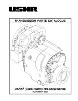
Control housing 1. Control housing 2. Stop cylinder Neutral position/Range changing 3. Magnetic solenoid interlock, 1st gear 4. Inhibitor valve, Control housing 5. Reverse light contact 6. Arm 7. Lever arm 8. Rod 9. Arm 10. Damper weight 11. Protective clamp 12. Gear selector lever position catch 13. Cam/1 gear catch 14. Axle 15. Gear selector lever 16. Cam/gear position 17. Reverse stop 18. Cover The control housing is cast from aluminium and is intended to transfer the motion of the gear stick to the gearbox shift rods. The position of the control housing can be adjusted and both left and right-hand drive trucks feature the same variant.
VT2214B, VT2514B and VT2814B - Module 15(24) - Page 1(1) - 2004-04-27 - 17:19
FM/FH version 2 trucks with a manual gearbox also have this variant of control housing with wire-cabling GSS-SRC, -RC. The reverse catch (17) is in a new position, and there is a new gear selector lever position catch (12), gear position cam (16) and damper weight (10) on the right-hand side of the control housing.
VT2214B, VT2514B and VT2814B - Module 15(24) - Page 1(1) - 2004-04-27 - 17:19
Electrical components A. Magnetic solenoid interlock prevents the driver from shifting into first gear if the speed is too high. This has been included to protect the engine and the clutch from overrevving. To activate this function, the following conditions must be met; 1. Low range position 2. Speed is over approx. 20 km/h, magnetic catch (3) activates cam (13), which prevents first gear being engaged. B. Split contact lights up the split lamp on the instrument panel at low split. (The split contact has different article numbers for direct-drive and overdrive gearboxes.) C. Reversing light contact transmits a signal activating the reversing light/warning once reverse gear is engaged. D. Sensor for range gear position provides the truck control unit with information regarding the range position, allowing the magnetic catch for first gear to be activated if shifting to the wrong gear. E. Magnetic valve, for range stop. This prevents the driver changing down to a low range once the speed of the truck reaches approx. 30 km/h. F. Speed sensor transmits a signal to the vehicle's electronic control unit (VECU) or the tachograph. G. Oil temperature sensor displays the temperature of the oil in the gearbox (optional).
VT2214B, VT2514B and VT2814B - Module 15(23) - Page 1(1) - 2004-04-27 - 11:28
Compressed air system 1. Range cylinder 2. Split cylinder 3. Inhibitor valve, range 4. Inhibitor valve, control housing 5. Inhibitor valve, split 6. Stop cylinder 7. Relay valve, range 8. Relay valve, split 9. Range inhibitor 10. Air filter 11. Gear lever Range cylinder (1) is a double-action pneumatic cylinder mounted on the rear end cover of the range-gear housing. Its purpose is to shift the range gear between the low and high range positions. Split cylinder (2) is a double-action pneumatic cylinder integrated into the clutch bell housing. Its purpose is to shift the splitter gear between the low and high split positions. Shut-off valve, range (3) during range changing, this helps the stop cylinder (6), which is located on the control housing, keep the basic gearbox in the neutral position. Shut-off valve, control housing (4) prevents range changing from occurring, once a gear has been engaged in the basic gearbox. Shut-off valve, split (5) prevents split gearchanging from occurring without the clutch pedal being depressed. Therefore, the supply of air to the split cylinder is controlled by a shut-off valve.
VT2214B, VT2514B and VT2814B - Module 16(23) - Page 1(1) - 2004-04-27 - 11:29
Stop cylinder (6) located on the control housing. This keeps the basic gearbox in neutral for as long as range changing continues, and prevents gearchanging from occurring without the cylinder being released. Relay valve, range (7) controls the flow of compressed air to either side of the cylinder depending on which gear is engaged. It also vents the range cylinder during gearchanging. The relay valve is integrated into the cover of the range cylinder. Relay valve, split (8) functions in the same way as the range cylinder relay valve. The relay valve is held in the low split position by the force of the spring. Once the button on the gear lever is moved to the high split position, actuating air is released to the relay valve counteracting the spring force and the control slide moves to the high split position. The relay valve has different article numbers for direct-drive and overdrive gearboxes. Range stop (9) prevents shifting to lowrange if the number of revolutions of the output shaft exceeds 700 rpm (approx. 30 km/h). The Vehicle Electronic Control Unit (VECU) receives a signal from the speed sensor and activates the magnetic valve, which cuts off the supply of actuating air to the range cylinder relay valve (7). Low range can then not be engaged. Air filter (10) located in the feed tubing of the compressed air system. It is located on the cover of the stop cylinder (6) on the control housing. Gear lever (11) contains the controls for actuating range and splitter gearchanging. The range control comprises one valve, which allows or cuts off actuating air to the range cylinder relay valve. The split gear is controlled in the same way.
VT2214B, VT2514B and VT2814B - Module 16(23) - Page 1(1) - 2004-04-27 - 11:29
Range Gear When shifting from high to low range, the valve in the gear lever knob opens and air goes into the solenoid valve (9) and the relay valve (7) if speed is below approx. 30 km/h. Shifting occurs when the gear lever passes neutral. The check valve (4) opens and air goes via the relay valve (7) to the range cylinder. The check valve (3) opens and will once again block the base gearbox in neutral with a lock cylinder (6). Click in the picture, where the arrow point, to start the animation.
VT2214B, VT2514B and VT2814B - Module 18(27) - Page 1(1) - 2004-05-04 - 11:25
Split gear In the FH truck, the check valve (5) to the split gear is connected to the clutch pedal. When shifting from low to high split, the valve opens in the gear lever and air goes to the relay valve (8). Shifting occurs when the clutch pedal is completely depressed, the check valve (5) is opened and the split cylinder (2) shifts. Click in the picture, where the arrow point, to start the animation.
VT2214B, VT2514B and VT2814B - Module 19(27) - Page 1(1) - 2004-05-04 - 11:26
Shift lock Function for check valve. When the gear lever is in neutral and the clutch is released, the cylinder (1) blocks the control with spring force in the cylinder. When the clutch is depressed, the air goes from the split check valve (5) to the bottom of the cylinder and overcomes the spring force, making it possible to engage the gear. This function prevents shifting without using of the clutch. Click in the picture, where the arrow point, to start the animation.
VT2214B, VT2514B and VT2814B - Module 20(27) - Page 1(1) - 2004-05-04 - 11:26
Lubrication system 1. Filter 2. Oil distribution pipes 3. Oil pump The gearbox is lubricated by a combination of pressure and splash lubrication. The oil is sucked up from the bottom of the gearbox through a filter to the oil pump, which is driven by the counter drive shaft. The oil is then pumped into the rear cover of the main shaft. The oil is pumped out into the oil distribution pipe, which is equipped with a number of holes, through which the oil is distributed to the bearings on the input shaft, main shaft and range gear. The channels then carry the oil to the bearings and synchromesh. Approximately 30% of the oil is distributed to the main shaft, while the remaining 70% is transferred to the range gear. On overdrive gearboxes, there is an additional oil distribution pipe mounted above the main shaft, which lubricates the splitter gear.
VT2214B, VT2514B and VT2814B - Module 17(23) - Page 1(1) - 2004-04-27 - 11:29
Oil pump 1. By-pass valve, clogged filter 2. By-pass valve, high pressure 3. Filter 4. Cover 5. Stay tube The oil pump is an excenter pump that is driven by the counter drive shaft via a gearwheel and a driven axle, which passes through the reverse axle. The driven axle is equipped with two needle bearings in the reverse axle. The pump has two by-pass valves. The first (1) ensures that the gearbox is lubricated if the filter becomes clogged, and the second (2) protects against high pressure in the system (e.g. a cold start). The valves are located in the pump housing and comprise a compression spring and valve cone. On the pressurised side of the pump, there is a full flow filter (3). This is located in the pump housing and is accessible from the outside. The filter is protected by a cover (4) on the range housing. There is a stay tube (5) in the oil filter, which prevents the filter from collapsing.
VT2214B, VT2514B and VT2814B - Module 18(23) - Page 1(1) - 2004-04-27 - 11:29
Oil cooler These gearboxes can be equipped with an oil cooler, which is mounted on the gearbox itself. A second oil filter cover is used, to which the oil filter is attached using screws. The oil is pumped first through the filter, then through the oil cooler and then out to the oil channels of the gearbox via the pipe (1). Coolant is supplied from the engine's cooling system to the oil cooler heat exchanger via pipes and hoses. A high-power oil cooler is available if required. The oil cooler in the diagram is then replaced by an adapter, which sends the oil to a larger cooler, which is mounted on the framework.
VT2214B, VT2514B and VT2814B - Module 20(24) - Page 1(1) - 2004-04-27 - 17:20
VT2814B Cooler The VT2814B and VTO2814B can be fitted with a new water/air cooler at the front of the truck. Vehicles which operate in climates where temperatures exceed 30°C, and have a high gross combination weight, require extra gearbox cooling.
VT2214B, VT2514B and VT2814B - Module 21(24) - Page 1(1) - 2004-04-27 - 17:20
Power take-off Volvo's power take-off are mounted directly on the rear end cover of the range housing. The power take-off is driven from the intermediate shaft in the gearbox. The oil system is combined with the gearbox. Gearchanging, variable-speed control and other functions can be controlled via the truck's electronic system. The following are examples of optional gearbox-driven power take-offs: PTR-FL Carrier, low-speed PTR-FH Carrier, high speed PTR-D Direct-driven hydraulic pump, low speed PTR-DM Direct-driven hydraulic pump, medium-high speed PTR-DH Direct-driven hydraulic pump, high speed PTRD-F Carrier, high speed for high power take-off PTRD-D Double direct-driven hydraulic pump, forward and reverse, high speed PTRD-D1 Double direct-driven carrier, reverse, high speed. Option for direct-driven hydraulic pump, forward, high speed PTRD-D2 Double driven two carrier, reverse, outer high speed, inner low speed. Option for direct-driven hydraulic pump, forward, high speed.
VT2214B, VT2514B and VT2814B - Module 21(23) - Page 1(1) - 2004-04-27 - 11:30
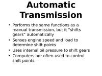
Gear lever variants With the introduction of the FM/FH "version 2" trucks 2002, Volvo's manual gearboxes now have one of these three gear levers with associated Gear Shifting System, GSS-SRC, or -RC. GSS-SRC = Gear Shifting System-Split Range Cable. RC = Range Cable. From left in the picture: The FH gear lever, right/left-hand drive, in the centre, FM, right-hand drive, and on the right, FM left-hand drive. Note the difference in the way the cables are pulled in the two variants. The gear lever is located in the floor of the cab and the cables are connected from below and from the front.
VT2214B, VT2514B and VT2814B - Module 22(23) - Page 1(1) - 2004-04-27 - 11:31
Cables Two gear shifting cables transfer power between the gear lever and the control housing on the gearbox. These are both push-pull wires, with one for shift stroke (grey) and one for select stroke (black). It is not possible to adjust the wires. In order to maintain good gearchanging quality, there is rubber damping at each end. The attachment system has a quick-release mechanism. The wires run beneath the floor of the cab forwards, around the cab tilt centre and between the cab tilt centre and the gearbox along the left frame side. The wire-cabling attachment system is colour-coded: Black, select stroke, gear lever White, shift stroke, gear lever Blue, shift stroke, control housing Orange, select stroke, control housing The wires are attached by clips to the cab and frame. When installing/replacing wires, it is extremely important that the instructions of service notice 432 116 are followed.
VT2214B, VT2514B and VT2814B - Module 23(23) - Page 1(1) - 2004-04-27 - 11:31
Aftermarket Training
Copyright 2004 Volvo Truck Corporation