![TrueBeam 2.5 Administration and Physics [PDF]](https://pdfs.asia/img/200x200/truebeam-25-administration-and-physics.jpg)
42 0 110 MB
TrueBeam 2.5 Administration and Physics TB201
TrueBeam 2.5 Administration and Physics
Abstract This TrueBeam 2.5 Administration and Physics manual is an educational aid for Varian TrueBeam machine.
Notice Information within this document is subject to change without notice and does not represent a commitment on the part of Varian. Varian is not liable for errors contained in this document or for incidental or consequential damages in connection with furnishing or use of this material. This document contains proprietary information protected by copyright. No part of this document may be reproduced, translated, or transmitted without the express written permission of Varian Medical Systems, Inc.
HIPAA Varian’s products and services are specifically designed to include features that help our customers comply with the Health Insurance Portability and Accountability Act of 1996 (HIPAA). The ARIA and VARiS Vision systems use a secure login process, requiring a user name and password that supports role-based access. Users are assigned to groups, each with certain access rights, which may include the ability to edit and add data or may limit access to data. When a user adds or modifies data within the database, a record is maintained of the data that was changed, the users ID and the date and time the changes were made. This establishes an audit trail that can be examined by authorized system administrators.
Trademarks Argus Software®, ARIA®, Clinac®, Exact® Arm, On-Board Imager®, SonArray®, Trilogy® and VARiS® are registered trademarks of Varian Medical Systems, Inc. 4D Integrated Treatment Console™, Acuity™, Eclipse™, Enhanced Dynamic Wedge™, FastPlan™, Millennium™ MLC, PortalVision™, Real-Time Position Management™, SmartBeam™, and TrueBeam™ are trademarks of Varian Medical Systems, Inc. All other trademarks or registered trademarks are the property of their respective owners. © 2015 Varian Medical Systems, Inc. All rights reserved.
© Varian Medical Systems For education purposes only © Varian Medical Systems, Inc. All rights reserved. FOR TRAINING PURPOSES ONLY
pg 2
TrueBeam 2.5 Administration and Physics DCID: TB2.5-CEM-02-B
Contacting Support Support services are available without charge during the initial warranty period. If you seek information not included in this publication, contact Varian Medical Systems: The most up-to-date contact information can be found at MyVarian.com
Ordering Additional Documents To order additional documents, contact Varian Medical Systems: The most up-to-date contact information can be found at MyVarian.com
Communicating Using the World Wide Web If you have access to the Internet, you will find Varian Medical Systems support at the following location: Oncology Systems: https://www.varian.com/oncology Select Service & Education for more information on various help resources
Sending E-Mail Support is available via e-mail, contact Varian Medical Systems: The most up-to-date contact information can be found at MyVarian.com
© Varian Medical Systems For education purposes only © Varian Medical Systems, Inc. All rights reserved. FOR TRAINING PURPOSES ONLY
pg 3
TrueBeam 2.5 Administration and Physics DCID: TB2.5-CEM-02-B
Document Conventions This workbook contains several icons that alert you to important or supplemental information. Icon
Name
Description
Note
Details supplemental information.
Important Note
Details critical supplemental information.
Tip
Details alternative methods or helpful hints.
Caution
Describes actions or conditions that could result in injury or damage to equipment, software, or data.
Warning
Describes actions or conditions that could result in serious injury or death.
© Varian Medical Systems For education purposes only © Varian Medical Systems, Inc. All rights reserved. FOR TRAINING PURPOSES ONLY
pg 4
TrueBeam 2.5 Administration and Physics DCID: TB2.5-CEM-02-B
Table of Contents Documentation and Help Resources
TAB 1
Documentation and Help Resources
System Overview
TAB 2
System Overview Software Overview Beam Production and Shaping Components, Dosimetry System
Administration
TAB 3
OSP, Users and Rights Creation of an OSP User Account TrueBeam System Administration
Service Mode for Physicists
TAB 4
Service Mode Overview Plan Delivery and Imaging in Service Mode Absolute Dose Calibration
© Varian Medical Systems For education purposes only © Varian Medical Systems, Inc. All rights reserved. FOR TRAINING PURPOSES ONLY
pg 5
TrueBeam 2.5 Administration and Physics DCID: TB2.5-CEM-02-B
Imaging & Geometry Calibrations
TAB 5
Imaging & Geometry System Calibrations Overview PVA Calibration Administration PVA Calibration Overview Imaging Mode Calibrations Imaging Calibrations Exercise Geometry Calibrations CBCT Calibrations Optical Camera Calibration
Power Up, Shut Down, Recovery, Power-Cycle
TAB 6
Power Up, Shut Down Recovery after Emergency Stop Daily, Weekly Power-Cycle Power Up from a Complete Power Off CTB-GE-791 (TrueBeam Power Up Instructions)
Treatment and Imaging Applications
TAB 7
Treatment Application Overview Imaging Procedures Overview
© Varian Medical Systems For education purposes only © Varian Medical Systems, Inc. All rights reserved. FOR TRAINING PURPOSES ONLY
pg 6
TrueBeam 2.5 Administration and Physics DCID: TB2.5-CEM-02-B
Clinical Applications
TAB 8
Plan QA in Treatment Mode Dry Run 2D-2D Match Marker Match 3D-3D Match 2D-3D Match Treatment with Automation Interrupted Treatment Treatment with Clearance Override Treatment with Auto Beam Hold Electron Plan Delivery, Custom Coding Unplanned Treatment Treatment with Respiratory Gating Advanced Reconstruction
Daily Machine Checks
TAB 9
Machine Performance Check Overview Using Machine Performance Check Machine QA Plans
© Varian Medical Systems For education purposes only © Varian Medical Systems, Inc. All rights reserved. FOR TRAINING PURPOSES ONLY
pg 7
TrueBeam 2.5 Administration and Physics DCID: TB2.5-CEM-02-B
Appendix
TAB 10
High-Intensity Beams Overview Imaging Application Overview Service Console Rights Optimizing Image Quality
© Varian Medical Systems For education purposes only © Varian Medical Systems, Inc. All rights reserved. FOR TRAINING PURPOSES ONLY
pg 8
TrueBeam 2.5 Administration and Physics DCID: TB2.5-CEM-02-B
Documentation and Help Resources
TAB 1
Documentation and Help Resources
1
© Varian Medical Systems For education purposes only © Varian Medical Systems, Inc. All rights reserved. FOR TRAINING PURPOSES ONLY
pg 9
TrueBeam 2.5 Administration and Physics DCID: TB2.5-CEM-02-B
Documentation and Help Resources
1
1
© Varian©Medical Varian Systems Medical Systems For training purposes only!
For education purposes only
pg 10
TrueBeam 2.5 Administration and Physics DCID: TB2.5-CEM-02-B
Documentation and Help Resources
1
© Varian©Medical Varian Systems Medical Systems For training purposes only!
For education purposes only
pg 11
TrueBeam 2.5 Administration and Physics DCID: TB2.5-CEM-02-B
Documentation and Help Resources
1
1
There are also release notes delivered with each software version or upgrade. CTBs (Customer Technical Bulletins) are available through MyVarian website. Help Desk can be contacted via phone or e-mail. - Remote help via Axeda Gateway through the HelpDesk.
© Varian©Medical Varian Systems Medical Systems For training purposes only!
For education purposes only
pg 12
TrueBeam 2.5 Administration and Physics DCID: TB2.5-CEM-02-B
Documentation and Help Resources
1
It is extremely important to read current Customer Release Notes after installation, upgrade and/or maintenance release. Current Customer Release notes can be found at MyVarian.com select Product Information>TrueBeam>Release Notes.
© Varian©Medical Varian Systems Medical Systems For training purposes only!
For education purposes only
pg 13
TrueBeam 2.5 Administration and Physics DCID: TB2.5-CEM-02-B
Documentation and Help Resources
1
1
TrueBeam 2.5 Customer Release Note and ICVI Release Note are available in Release Notes section on MyVarian.com website.
© Varian©Medical Varian Systems Medical Systems For training purposes only!
For education purposes only
pg 14
TrueBeam 2.5 Administration and Physics DCID: TB2.5-CEM-02-B
Documentation and Help Resources
1
Available in Reference Materials section on MyVarian.com website.
© Varian©Medical Varian Systems Medical Systems For training purposes only!
For education purposes only
pg 15
TrueBeam 2.5 Administration and Physics DCID: TB2.5-CEM-02-B
Documentation and Help Resources
1
1
For urgent issues dial 1.888.VARIAN5; If the issue does not require immediate attention or a document needs to be attached, send an e-mail.
© Varian©Medical Varian Systems Medical Systems For training purposes only!
For education purposes only
pg 16
TrueBeam 2.5 Administration and Physics DCID: TB2.5-CEM-02-B
Documentation and Help Resources
1
Axeda Gateway establishes a remote connection with TrueBeam workstation via the internet. Hospital firewall must have an open communication port for Axeda Gateway. Help desk or service rep can only connect to the workstation when a remote session is opened by the customer.
© Varian©Medical Varian Systems Medical Systems For training purposes only!
For education purposes only
pg 17
TrueBeam 2.5 Administration and Physics DCID: TB2.5-CEM-02-B
Documentation and Help Resources
1
1
All information for all the products can be accessed with one login. Customers are given access to information based upon which products they have purchased.
© Varian©Medical Varian Systems Medical Systems For training purposes only!
For education purposes only
pg 18
TrueBeam 2.5 Administration and Physics DCID: TB2.5-CEM-02-B
Documentation and Help Resources
1
© Varian©Medical Varian Systems Medical Systems For training purposes only!
For education purposes only
pg 19
TrueBeam 2.5 Administration and Physics DCID: TB2.5-CEM-02-B
Documentation and Help Resources
1
1
© Varian©Medical Varian Systems Medical Systems For training purposes only!
For education purposes only
pg 20
TrueBeam 2.5 Administration and Physics DCID: TB2.5-CEM-02-B
Documentation and Help Resources
1
© Varian©Medical Varian Systems Medical Systems For training purposes only!
For education purposes only
pg 21
TrueBeam 2.5 Administration and Physics DCID: TB2.5-CEM-02-B
Documentation and Help Resources
1
1
© Varian©Medical Varian Systems Medical Systems For training purposes only!
For education purposes only
pg 22
TrueBeam 2.5 Administration and Physics DCID: TB2.5-CEM-02-B
Documentation and Help Resources
1
The Certificate Manager can be accessed directly by visiting www.variancertificatemanager.com Alternatively, the Certificate Manager can be accessed from www.varian.com or www.MyVarian.com: www.varian.com -> Oncology -> Service & Education -> Education & Training -> Certificate Manager MyVarian.com -> Training & Education -> Certificate Manager
© Varian©Medical Varian Systems Medical Systems For training purposes only!
For education purposes only
pg 23
TrueBeam 2.5 Administration and Physics DCID: TB2.5-CEM-02-B
Documentation and Help Resources
1
1
Certificate Manager can be accessed through MyVarian.com -> Training & Education -> Certificate Manager
© Varian©Medical Varian Systems Medical Systems For training purposes only!
For education purposes only
pg 24
TrueBeam 2.5 Administration and Physics DCID: TB2.5-CEM-02-B
Documentation and Help Resources
1
© Varian©Medical Varian Systems Medical Systems For training purposes only!
For education purposes only
pg 25
TrueBeam 2.5 Administration and Physics DCID: TB2.5-CEM-02-B
Documentation and Help Resources
1
1
© Varian©Medical Varian Systems Medical Systems For training purposes only!
For education purposes only
pg 26
TrueBeam 2.5 Administration and Physics DCID: TB2.5-CEM-02-B
System Overview
TAB 2
System Overview Software Overview Beam Production and Shaping Components, Dosimetry System
2
© Varian Medical Systems For education purposes only © Varian Medical Systems, Inc. All rights reserved. FOR TRAINING PURPOSES ONLY
pg 27
TrueBeam 2.5 Administration and Physics DCID: TB2.5-CEM-02-B
System Overview
TrueBeam System Overview 2
Procedure
2
Objectives: After completing this module the student will have performed the following tasks using the TrueBeam Administration and Physics manual as a resource: 1. Identified the major HW components of the TrueBeam system, their placement, role in the system and basic parameters. 2. Understood TrueBeam control system. 3. Reviewed TrueBeam safety components.
Procedure Content: Control Room Components: 1. Alphanumeric keyboard and mouse 2. Workstation control console 3. Console electronics cabinet 4. Console imaging cabinet 5. CCTV monitors 6. Workstation monitors Treatment Room Components: 7. Clinac stand 8. Clinac gantry a. kVS b. kVD
© Varian Medical Systems System Overview For education purposes © [2013] Varian Medical Systems,only Inc. All rights reserved. Document Version 1.0
pg 28
TrueBeam 2.5 Administration and Physics 1 DCID: Produced by Global TB2.5-CEM-02-B Standards and Content Revised [01/01/2001]
System Overview
c.
MVD
9. Clinac couch a. Side panels b. Hand pendants 10. Respiratory Gating camera 11. CCTV camera(s)
2
12. Live view camera TrueBeam Control System Components Main TrueBeam Safety Features
References: P1005923-002-B – TrueBeam Technical Reference Guide – Volume 1; chapters 2, 5, 7, 9, 10, 12, 13, appendix B. P1005924-001-A – TrueBeam Technical Reference Guide – Volume 2: Imaging; chapters 2, 3, 4, 5, 6, 12, appendix B. P1005922-001-A – TrueBeam Instructions for Use – chapter 6, appendix G. P1005927-001-A – TrueBeam Quick Reference Guide. RAD 10094L – TrueBeam™ System Specifications. P1007370-001-A – TrueBeam™ IEC Accompanying Documents Functional Performance Characteristics, appendix E.
© Varian Medical Systems System Overview For education purposes © [2013] Varian Medical Systems,only Inc. All rights reserved. Document Version 1.0
pg 29
TrueBeam 2.5 Administration and Physics 2 DCID: Produced by Global TB2.5-CEM-02-B Standards and Content Revised [01/01/2001]
System Overview
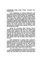
A. Control Room Components 1. Typical Control Room layout. Control Room consists of Control Console Area (A) and Electronics Cabinets (B), see Figure 1.
2
2
A
B
Figure 1: General Control Console Area, A – Control Console Area; B – Electronics Cabinets
© Varian Medical Systems System Overview For education purposes © [2013] Varian Medical Systems,only Inc. All rights reserved. Document Version 1.0
pg 30
TrueBeam 2.5 Administration and Physics 3 DCID: Produced by Global TB2.5-CEM-02-B Standards and Content Revised [01/01/2001]
System Overview
2. Control Console Area, see Figure 2, includes the following system components: Workstation monitors
2 ‘Imaging’
‘Treatment
CCTV monitor
CCTV monitor Control console
Alphanumeric KBD
Mouse
Figure 2: Control Console Area
a) Workstation monitors are both connected to TrueBeam workstation and provide a visual interface which allows interaction with software installed and running on TrueBeam workstation. ‘Treatment’ monitor shows main user-facing application, ‘imaging’ monitor shows imaging related information with respect to main running application, b) CCTV monitors enable therapist to monitor treatment room from control console area. They have button controls for camera zoom, camera navigation, navigation and zoom reset, ON/OFF, brightness and contrast. They also have adjustable tilt, c) Mouse can be smoothly dragged between both monitors, d) Alphanumeric keyboard (KBD) is used if user input is needed,
© Varian Medical Systems System Overview For education purposes © [2013] Varian Medical Systems,only Inc. All rights reserved. Document Version 1.0
pg 31
TrueBeam 2.5 Administration and Physics 4 DCID: Produced by Global TB2.5-CEM-02-B Standards and Content Revised [01/01/2001]
System Overview
e) and Control Console, see Figure 3:
Emergency stop
Lock & Key
Imager selection
2
2
Intercom system
Backup MU display
Beam controls Motion controls
Figure 3: Control Console
Control Console controls are separated into several logical sections – see Figure 3. The controls allow remote motions, kV and MV beams, communication with patient inside in the treatment room and basic safety operations: Lock and key - If key is in locked position ( treatment and imaging are not available.
) motions from the console as well as
Emergency stop button stops any beam and motion and shuts off high voltage power. Console area workstations remain powered on. Backup MU counter shows delivered MU even if there is no electrical power (at least 30 minutes after power was lost). Imager Selection - allows to select imaging arm to be controlled from control console. Cycles through 3 options: kV (kVS and kVD arms selected), MV (MVD arm selected) and MV + kV (MV and kV imaging arms selected). Motion Selection buttons allow selecting axes to be controlled remotely from control console. Orange color of the button indicates that the actual axis position differs from the axis position in the plan more than is allowed for the axis by the tolerance table. Green flashing label over the button indicates that the axis has been selected to be moved from the console and will move when Motion Enable buttons are pressed and held down.
© Varian Medical Systems System Overview For education purposes © [2013] Varian Medical Systems,only Inc. All rights reserved. Document Version 1.0
pg 32
TrueBeam 2.5 Administration and Physics 5 DCID: Produced by Global TB2.5-CEM-02-B Standards and Content Revised [01/01/2001]
System Overview
Motion Enable – both buttons need to be pressed and held down to move selected axis (or more axes) to planned position(s). Motion Enable buttons are lit up when active. Clearance Override – in conjunction with one or both Motion Enable buttons it can be used to override ‘low clearance’ treatments for which Machine Protection and/or Patient Protection systems would report a collision disallowing continuation of the treatment.
Tip: Clearance Override functionality has to be enabled in Treatment mode each session it is to be used and for each of the protection systems to be overridden. Successful authorization requires Override Patient Protection user right.
Table 1 and Table 2 describe roles of Beam Controls and Motion Selection buttons.
Beam Control Button
Function:
Preview
Plan/Field preview mode, ‘No Mode Up’
Prepare
Transfers selected field parameters to the machine (previously called ‘Mode Up’) MLC and jaws move to planned positions if not there yet without need to press and hold Motion Enable Indicates that MV beam preparation was successful, no active interlocks.
MV Ready
Stays lit for several second waiting for confirmation from user. If MV beam is not confirmed by pressing and holding this button down, the system returns to Prepare To confirm MV beam, press and hold this button until it goes dark and MV Beam On button becomes lit Turns on the MV beam for treatment and/or imaging
MV Beam On
If held down the MV beam is temporarily paused for the time the button is held down
Beam Off
Shuts off the active beam (MV and/or kV)
kV Beam On
Prepares and turns on the kV beam for imaging Table 1: Beam Controls
© Varian Medical Systems System Overview For education purposes © [2013] Varian Medical Systems,only Inc. All rights reserved. Document Version 1.0
pg 33
TrueBeam 2.5 Administration and Physics 6 DCID: Produced by Global TB2.5-CEM-02-B Standards and Content Revised [01/01/2001]
2
System Overview
Motion Selection
Function: Selects planned position or in the absence of a plan to the default extended position to be applied to selected imaging arms when Motion Enable are pressed and held down
To Plan Selects a preset midway position which avoids exposure to imaging panels during treatment to be applied to selected imaging arms when Motion Enable are pressed and held down
2 Mid
Selects fully retracted position to be applied to selected imaging arm(s) when Motion Enable are pressed and held down Retract Select couch linear axes (Vrt, Lng, Lat) to be moved when Motion Enable buttons are pressed and held down. If PerfectPitch 6DOF couch available this button also applies to Roll, Pitch Couch Linear Selects gantry and collimator ( including jaws ) axes to be moved to planned position(s) by pressing Motion Enable Gantry Selects couch rotation to be applied by Motion Enable
Couch Rtn Table 2: Motion Selection Controls
Note: Gantry and couch cannot be moved at the same time from outside of the vault. If only one button is orange, the axes it represents are automatically selected to be moved by Motion Enable ( label over the button is flashing in green ).
© Varian Medical Systems System Overview For education purposes © [2013] Varian Medical Systems,only Inc. All rights reserved. Document Version 1.0
pg 34
TrueBeam 2.5 Administration and Physics 7 DCID: Produced by Global TB2.5-CEM-02-B Standards and Content Revised [01/01/2001]
2
System Overview
3. Electronics Cabinets – Control and Imaging Cabinets: •
Control Cabinet, see Figure 4, holds the following components:
a) TrueBeam workstation – runs user-facing software applications, provides access to R&V system and patient data, b) In-Room Monitor (IRM) workstation – hosts ‘in-room’ monitors that show plan relevant machine and patient information inside in the treatment room, c) Service workstation – runs remote access and machine monitoring software,
2
d) Node Electronics Assembly – contains control system nodes including Supervisor, power supply and network switch for nodes communications, e) UPS and external batteries, firewall, ethernet switch (Imaging and Workstation networks), Live View Camera control unit and service connectors.
Service connectors
Firewall, Node Electronics Assembly Ethernet Switch, Live View Camera control unit
Service WS IRM WS TrueBeam WS
UPS
Extended batteries
Figure 4: Control Cabinet
© Varian Medical Systems System Overview For education purposes © [2013] Varian Medical Systems,only Inc. All rights reserved. Document Version 1.0
pg 35
TrueBeam 2.5 Administration and Physics 8 DCID: Produced by Global TB2.5-CEM-02-B Standards and Content Revised [01/01/2001]
System Overview
•
Imaging Cabinet, see Figure 5, holds the following components:
a) CBCT Reconstructor – reconstructs CBCT from kV projections acquired during gantry rotation, b) XI (X-ray Imaging) – part of the control system responsible for kV imaging, MV imaging, Respiratory Gating; controls X-ray generator, c) Power supply for XI.
2
2
XI power supply
XI
CBCT Reconstructor
Figure 5: Imaging Cabinet
© Varian Medical Systems System Overview For education purposes © [2013] Varian Medical Systems,only Inc. All rights reserved. Document Version 1.0
pg 36
TrueBeam 2.5 Administration and Physics 9 DCID: Produced by Global TB2.5-CEM-02-B Standards and Content Revised [01/01/2001]
System Overview
B. Treatment Room Components 1. Figure 6 shows typical component deployment in Treatment Room. Respiratory Gating camera
Live View camera
Gantry stand
CCTV cameras
2
Gantry with imaging arms
In-room monitors
Treatment couch
Modulator
Figure 6: Treatment Room Components
2. CCTV cameras – capture view of the treatment room which is then displayed on CCTV monitors in the control console area. View angle and zoom can be adjusted using the controls on the monitors. System is configurable for up to 6 CCTV monitoring devices. 3. Live view camera – captures treatment room view which is then displayed in real time in treatment application. Machine motions and/or collisions detected by Protection systems are displayed as color overlays on this view. See Figure 7. a) Orange arrows – motions to be done to move to planned position for active field. b) Blue arrows – indication of motions done during treatment ( for example gantry motion during arc treatment ). c) Red overlay displayed over couch/collimator/imaging panel(s) – indication of collision detected by one of Protection systems. d) Yellow overlay displayed over couch/collimator/imaging panel(s) – warning that indicated machine parts are about to collide.
© Varian Medical Systems System Overview For education purposes © [2013] Varian Medical Systems,only Inc. All rights reserved. Document Version 1.0
pg 37
TrueBeam 2.5 Administration and Physics 10 DCID: Produced by Global TB2.5-CEM-02-B Standards and Content Revised [01/01/2001]
System Overview
2
2
Figure 7: Live View Display in Treatment Application
4. Respiratory Gating Camera, see Figure 8 – Polaris Spectra camera from NDI used to track patient respiratory motion by tracking passive marker block placed on the patient: Status LEDs, laser and laser activation button
Position sensors and illuminators
Reflective markers
Figure 8: Respiratory Gating Camera (top) and Marker Block (bottom)
a) Camera directly produces stream containing marker block position and its orientation (x, y, z, roll, pitch, yaw ) which is received by the XI. b) Permanently connected to XI power supply to avoid long warm-up times which can be, from cold start, anywhere between 10 minutes and 2 hours.
© Varian Medical Systems System Overview For education purposes © [2013] Varian Medical Systems,only Inc. All rights reserved. Document Version 1.0
pg 38
TrueBeam 2.5 Administration and Physics 11 DCID: Produced by Global TB2.5-CEM-02-B Standards and Content Revised [01/01/2001]
System Overview
c) Camera has a bump sensor built-in. Detected impact is indicated by LEDs on the camera. Possible system states are explained in Table 3.
1) 2) 3) 4) 5)
Laser aperture Error LED (amber) Laser Activation Button Power LED (green) Status LED (green)
2
Power LED
Status LED
Error LED
State
Flashing
Any
Any
Warm up
Solid
Solid
Off
Ready for use, no faults
Solid
Solid
Flashing
Minor recoverable fault (for example bump detected). Does not prevent system operation
Solid or Off
Solid
Solid
Major recoverable fault. System will not operate until fixed
Solid
Off
Solid
Non-recoverable fault. Service required
Table 3: Position Sensor States
d) Marker block is made of a lightweight plastic material ABS 757. e) Marker block white cross lines are used to align marker block with isocenter for camera calibration.
Note: Intercom microphones inside in the treatment room are typically close to Live View and Gating cameras.
© Varian Medical Systems System Overview For education purposes © [2013] Varian Medical Systems,only Inc. All rights reserved. Document Version 1.0
pg 39
TrueBeam 2.5 Administration and Physics 12 DCID: Produced by Global TB2.5-CEM-02-B Standards and Content Revised [01/01/2001]
System Overview
5. In-room monitors – system includes 2 in-room monitors that display relevant patient and machine information for operator inside in the treatment room. They are mounted side-by-side where operator can easily observe the data while still watching the patient. Machine monitor displays machine parameter information and Patient monitor shows patient information and treatment plan setup data. See Figure 9 and Figure 10. a) Patient monitor screen is divided into 4 quadrants. Upper right and lower left show setup pictures attached to the active field in R&V/TPS. Lower right shows patient picture. Patient first name, last name, patient ID, plan ID and patient orientation are displayed in bottom right corner of these views. Upper left quadrant can display Setup Notes, Activity notes or Fields. Selection can be made using navigation buttons on the hand pendant. Selecting Fields automatically starts Dry Run. Dry Run can be finished by selecting Setup Notes tab or pressing Done button in Treatment Application.
2
2
Important Note: Dry Run is a practice run of a treatment plan. Performing a Dry Run lets you check machine movement for possible collision and other problems before the patient is treated. Varian strongly recommends that Dry Run is performed each time treatment includes movement of imaging arms and/or gantry to avoid patient injury and/or equipment damage.
Figure 9: Patient Monitor Example
© Varian Medical Systems System Overview For education purposes © [2013] Varian Medical Systems,only Inc. All rights reserved. Document Version 1.0
pg 40
TrueBeam 2.5 Administration and Physics 13 DCID: Produced by Global TB2.5-CEM-02-B Standards and Content Revised [01/01/2001]
System Overview
b) Machine monitor – shows planned and actual positions of machine axes. Blue bar on the right side shows machine status messages ( upper half ) and routine interlocks ( lower half ). Blue bar on the top includes patient and selected/active field information. Orange background for actual machine axis position value indicates that the actual axis position differs from the planned axis position more than is allowed for the axis by the tolerance table. See Figure 10.
Status messages
2
Routine interlocks
Figure 10: Machine Monitor Example
© Varian Medical Systems System Overview For education purposes © [2013] Varian Medical Systems,only Inc. All rights reserved. Document Version 1.0
pg 41
TrueBeam 2.5 Administration and Physics 14 DCID: Produced by Global TB2.5-CEM-02-B Standards and Content Revised [01/01/2001]
System Overview
6. Modulator - contains components that transform AC electricity into the required high voltage and distribute it to primary and support systems of the clinac. It contains main power controls, system circuit breakers and other controls and indicators. Can be also located in a dedicated room separate from treatment.
2
7. Clinac stand – support structure for the Gantry. TrueBeam platform features 2 different stand installation versions – standard (not in production with TrueBeam 2.5, still available on upgraded machine) and small vault configuration, see Figure 11. Small vault configuration stand is about 40cm ( 15.6” ) shorter than standard and does not require access from the back ( can be installed directly against back wall ) which makes it suitable for smaller treatment rooms. Because of significant reduction in volume inside, most of the stand components and some gantry components have been re-packaged/re-designed in order to fit reduced space. Stand contains following vital and supporting clinac components (see also Figure 12 and Figure 13): a) Water cooling components:
Water tank – contains up to 12 gallons of distilled water mixed corrosion inhibitors and biocides (included with TrueBeam as additive kit).
Water pump – provides adjustable water flow-rate and pressure.
Heat exchanger – component where internal water and facility water flow past each other and exchange heat, cools down internal water.
Strainer – removes large debris.
3-way valve – controls rate of facility water flowing in TrueBeam cooling system, which affects internal water cooling rate.
Flow, temperature and water level sensors.
The cooling system keeps the water temperature between 38.2 °C and 41.8 °C. If the temperature reaches 45 °C for more than 5 minutes, minor fault would prevent the machine from beaming on. If water overheats to 48 °C major fault cause power to be shut down and de-energize major heat-producing components.
b) Fans – interior of the stand is cooled by air. c) Klystron – linear vacuum tube microwave amplifier. d) X-ray generator and X-ray tube voltage transformer. e) SF6 system – waveguide between klystron and clinac accelerator structure is filled with dielectric SF6 gas to suppress arcing inside the waveguide. System consists of gas tank, filter, pressure sensor and relief and solenoid valves. If pressure is below 30.5 psig the control system opens the solenoid valve to increase the pressure. Valve is then closed when pressure rises above 33.5 psig. f)
Power supplies – accelerator solenoid, klystron solenoid, bending magnet, RF driver.
g) Control system PCBs.
© Varian Medical Systems System Overview For education purposes © [2013] Varian Medical Systems,only Inc. All rights reserved. Document Version 1.0
pg 42
TrueBeam 2.5 Administration and Physics 15 DCID: Produced by Global TB2.5-CEM-02-B Standards and Content Revised [01/01/2001]
2
System Overview
h) Backup motion controller – allows gantry and couch motions when machine is without external power. For service use only.
2
Figure 11: Stand Options, Standard (left) and Small Vault Configuration (right)
© Varian Medical Systems System Overview For education purposes © [2013] Varian Medical Systems,only Inc. All rights reserved. Document Version 1.0
pg 43
TrueBeam 2.5 Administration and Physics 16 DCID: Produced by Global TB2.5-CEM-02-B Standards and Content Revised [01/01/2001]
System Overview
kV generator voltage transformer
2
2 Waveguide
SF6 dryer
Backup motion controller
SF6 solenoid valve
Water flow sensors SF6 pressure gauge Emergency Off button SF6 pressure monitor
Klystron
Shut off valve
SF6 tank
Figure 12: Stand Components (Gantry Right)
© Varian Medical Systems System Overview For education purposes © [2013] Varian Medical Systems,only Inc. All rights reserved. Document Version 1.0
pg 44
TrueBeam 2.5 Administration and Physics 17 DCID: Produced by Global TB2.5-CEM-02-B Standards and Content Revised [01/01/2001]
System Overview
kV generator
2 Klystron solenoid PS
Acc. solenoid PS
Bending magnet PS
RF driver PS
Cooling system funnel
Sliding panels with control system PCBs
Emergency Off button
Water pressure gauge
Figure 13: Stand Components (Gantry Left)
© Varian Medical Systems System Overview For education purposes © [2013] Varian Medical Systems,only Inc. All rights reserved. Document Version 1.0
pg 45
TrueBeam 2.5 Administration and Physics 18 DCID: Produced by Global TB2.5-CEM-02-B Standards and Content Revised [01/01/2001]
System Overview
kV generator
2
2 Water funnel on a swing arm
Emergency Off button
Water flow sensors
Klystron
SF6 tank
Water cooled pulse tank Figure 14: ‘Slim’ Stand Components (Gantry Right)
© Varian Medical Systems System Overview For education purposes © [2013] Varian Medical Systems,only Inc. All rights reserved. Document Version 1.0
pg 46
TrueBeam 2.5 Administration and Physics 19 DCID: Produced by Global TB2.5-CEM-02-B Standards and Content Revised [01/01/2001]
System Overview
kV generator
2
RF driver
3-in-1 power supply (KSOL, ASOL, BMAG)
Swing panel with controller PBCs
Emergency Off button
Pump stand with pump
Figure 15: ‘Slim’ Stand Components (Gantry Left)
© Varian Medical Systems System Overview For education purposes © [2013] Varian Medical Systems,only Inc. All rights reserved. Document Version 1.0
pg 47
TrueBeam 2.5 Administration and Physics 20 DCID: Produced by Global TB2.5-CEM-02-B Standards and Content Revised [01/01/2001]
System Overview
8. Clinac couch – patient positioning platform which provides a travel range to accommodate a wide variety of treatment techniques. Consists of a couch top and a pedestal. a) Inside in the treatment room couch can be operated from Side Panels and/or Hand Pendants. b) In addition to standard 4DoF couch, TrueBeam 2.0 (and higher) platform also offers 6DoF couch as an option. Varian PerfectPitch™, see Figure 16, adds 2DoF (roll – lateral tilt, pitch – longitudinal tilt ) to 4DoF couch pedestal. PerfectPitch requires new couch pedestal and supports several different couch tops – Varian IGRT, kVue, Calypso kVue.
2
Pitch and roll values are not in treatment plan, they are considered axes that can correct for deviations in patient setup and can only be applied from control console or hand pendant in the treatment room as a result of patient setup verification process. Custom roll and pitch can also be applied in Service mode; either using the hand pendants or control console.
2
Roll and pitch applied for the session may be saved to the treatment database but will not be imported for subsequent session. Roll and pitch zero automatically when couch is lowered 40cm below isocenter. Maximum pitch and roll angular rotations are ±3°.
2DoF Roll and Pitch mechanism
Figure 16: PerfectPitch™
c) Operating limits in IEC 61217 Scale:
Lateral limits – -24.5 cm to +24.5 cm.
Longitudinal limits - +15.5 cm to +160.5 cm.
Rotation - +95° to +265°.
© Varian Medical Systems System Overview For education purposes © [2013] Varian Medical Systems,only Inc. All rights reserved. Document Version 1.0
pg 48
TrueBeam 2.5 Administration and Physics 21 DCID: Produced by Global TB2.5-CEM-02-B Standards and Content Revised [01/01/2001]
System Overview
Vertical Limits – depend on couch top. See Table 4. Couch top
Robotics (Roll and Pitch)
Vertical Range
IGRT
None
-66.5 to +40.5 cm
IGRT
Varian
-58.0 to +40.5 cm
3rd party : kVue
None
-66.5 to +40.5 cm
3rd party : kVue
Varian
-53.5 to +40.5 cm
3rd party : BrainLab
3rd party : BrainLab
-56.3 to +40.5 cm
2
Table 4: Vertical Travel Range
4DoF Max patient load
6DoF
227 kg ( IGRT, kVue, Calypso kVue )
200 kg ( IGRT)
Min. patient load height
~ 63 cm
~ 72 cm
Vertical travel range
~ 106 cm
~ 98 cm
155 kg (kVue, Calypso kVue )
Table 5: 4DoF vs 6DoF Comparison
d) TrueBeam couch includes a feature called Couch Compensation. Couch Compensation takes account of small deflections in the couch structure itself – as couch longitudinal and lateral axes ( and/or roll and pitch if applicable) are moved small elastic deflections of couch top occur which have small but measurable influence on position of couch top with respect to isocenter, see Figure 17. Couch compensation converts couch top actual position into precise motor position and adjusts couch vertical to keep target at isocenter which can be visible as small amount of vertical motion when longitudinal, lateral (and/or roll and pitch if applicable ) are changing. In float mode the compensation function calculates the effective vertical axis position for actual longitudinal, lateral (and/or roll and pitch if applicable ) positions of the couch top which appears as a change in the vertical axis position displayed during float mode motion.
Figure 17: Couch Compensation
© Varian Medical Systems System Overview For education purposes © [2013] Varian Medical Systems,only Inc. All rights reserved. Document Version 1.0
pg 49
TrueBeam 2.5 Administration and Physics 22 DCID: Produced by Global TB2.5-CEM-02-B Standards and Content Revised [01/01/2001]
System Overview
e) Hand pendants – there are two identical hand pendants connected to couch pedestal, one on each side of couch. They are used to move the machine axes.
Display on top of the pendant shows Gantry position and currently selected imaging arms.
Pendant display
Button
Automatic motions
Selected imager(s) motions
2
Description Turns treatment room lights on/off.
Turns field light on/off
Turns the Optical Distance Indicator (ODI) on/off
Turns the room lasers on/off
Thumbwheels function selectors
Thumbwheels for manual motions
Turns the pendant flashlight on/off. The flashlight is located on the back of pendant Toggles the radiation field aperture between plan and open. For dynamic MLC fields the button toggles between Complete Irradiated Area Outline (CIAO) and open. Moves the selected imager(s) to planned position or default extended position if there is no plan Moves the selected imager(s) to midway position to provide clearance for motions and minimize imaging panel exposure
Moves the selected imager(s) to fully retracted position
pg 50
TrueBeam 2.5 Administration and Physics 23 DCID: Produced by Global TB2.5-CEM-02-B Standards and Content
Motion Enable Figure 18: Hand Pendant
© Varian Medical Systems System Overview For education purposes © [2013] Varian Medical Systems,only Inc. All rights reserved. Document Version 1.0
Revised [01/01/2001]
2
System Overview
Button
Description Service button allows pendant test and calibrations of the pendant thumbwheels. Requires additional steps to be done in Service application. Navigation buttons – cycle through tabs and panels on the Patient Monitor – can be used to start/stop Dry Run.
2
Expands the selected view on the Patient Monitor.
Restarts the Dry Run or allows cancelling the Dry Run with automation.
Moves the couch longitudinally, laterally and vertically to the planned position. Motion needs to be allowed by pressing Motion Enable bars. Moves gantry and collimator axes to plan.
Rotates the couch to the planned position.
Enables the thumbwheels to move the collimator, gantry and couch manually. Also, can be used to enable the thumbwheels to apply custom roll and pitch when Service Mode or Select Major Mode is opened at the console. Selects the imager(s) to move with imaging arm positioning buttons and enables thumbwheels to move the selected MV or kV imaging arm. The selected arm(s) appears on pendant display. Imager selection is specific to each pendant. Enables the thumbwheels to move collimator jaws manually. Pressing the button repeatedly cycles through different asymmetry motion modes. Table 6: Hand Pendant Buttons
Important Note: Automatic Motion buttons, when backlit in orange color, can be used to move the machine to plan positions. For the Automatic Motion buttons on the paddle, the system uses very tight internal tolerances which may be different from plan. Thus these buttons still can be backlit in orange color, even when control console buttons are not orange ( difference between actual and plan is less than plan tolerance ).
© Varian Medical Systems System Overview For education purposes © [2013] Varian Medical Systems,only Inc. All rights reserved. Document Version 1.0
pg 51
TrueBeam 2.5 Administration and Physics 24 DCID: Produced by Global TB2.5-CEM-02-B Standards and Content Revised [01/01/2001]
System Overview
f)
2
Couch side panels – buttons with same symbols as on the hand pendant have same functionality.
Figure 19: Couch Side Panel
Note: TrueBeam v2.0 (and higher) new installs have additional new buttons on the side panel whether the couch is 6DOF or not.
Button
Function
Level couch top ( zero roll and pitch )
Future development, not yet functional buttons.
Table 7: TrueBeam 2.0 (and Higher) New Couch Side Panel Buttons
Note: EMO Vertical allows lowering the couch only.
© Varian Medical Systems System Overview For education purposes © [2013] Varian Medical Systems,only Inc. All rights reserved. Document Version 1.0
pg 52
TrueBeam 2.5 Administration and Physics 25 DCID: Produced by Global TB2.5-CEM-02-B Standards and Content Revised [01/01/2001]
2
System Overview
9. Clinac gantry – contains parts that generate and shape the beam for treatment. Supports the imaging arms which provide kV and MV imaging. Gantry is connected to the stand and is rotated as a unit. See Figure 20.
2
Figure 20: Gantry
Gantry Specifications
Specifications
Rotational accuracy
≤ 0.3 degrees
Rotation range
±185° from the vertical
Rotation speed
Variable from 0 to 1 RPM
Gantry and collimator isocenter accuracy
≤ 0.5 degrees
Gantry, collimator and couch isocenter accuracy
≤ 0.75 degrees
Target to gantry axis distance
100 ± 0.2 cm Table 8: Gantry Specification
© Varian Medical Systems System Overview For education purposes © [2013] Varian Medical Systems,only Inc. All rights reserved. Document Version 1.0
pg 53
TrueBeam 2.5 Administration and Physics 26 DCID: Produced by Global TB2.5-CEM-02-B Standards and Content Revised [01/01/2001]
System Overview
a) Collimator – contains important beam shaping components such as X and Y jaws and MLC. X and Y jaws are independent, X jaws move in same direction as MLC leaves along linear path, Y jaws move along arc trajectory. The collimator has attachments that accept wedge filters, shadow block trays, compensating filters, electron applicators and other accessories to modify the treatment beam further, see Figure 21. Custom coding is available for selected accessories - the collimator electronics reads the codes placed on trays of patient specific, beam modifying accessories (e.g. electron cut-out ), see Figure 22.
2
2
Figure 21: Collimator and its Accessories
© Varian Medical Systems System Overview For education purposes © [2013] Varian Medical Systems,only Inc. All rights reserved. Document Version 1.0
pg 54
TrueBeam 2.5 Administration and Physics 27 DCID: Produced by Global TB2.5-CEM-02-B Standards and Content Revised [01/01/2001]
System Overview
2
Figure 22: Custom Coding
Collimator Performance Specifications
Specifications
Rotational accuracy
≤ 0.5 degrees
Rotational reproducibility
≤ 0.3 degrees
Rotation range
±175°
Coincidence of light field and radiation field (50% isodensity line) 1.5 mm Cross hair intersection alignment to collimator
±0.5 mm
Rotational speed, no accessories
Variable from 0 to 2.5 RPM
Rotational speed, with accessories
Variable from 0 to 1 RPM
Optical range finder
70 - 156 cm range, 0.5 cm resolution, accurate to ±0.1 cm at 100 cm
Mechanical front pointer
70 - 110 cm range, 0.2 cm resolution, accurate to ±0.1 cm, at 100 cm Table 9: Collimator Specifications
Independent Upper and Lower Jaws
Specifications
Upper jaw positional accuracy
±2 mm for static fields
Lower jaw positional accuracy
±1 mm for static fields
Travel range – lower jaws
-2 cm to +20 cm
Travel range – upper jaws
-10 cm to +20 cm
Jaw speed
Variable, 0 cm/s to a maximum speed of 2.5 cm/s Table 10: Jaw Specifications
© Varian Medical Systems System Overview For education purposes © [2013] Varian Medical Systems,only Inc. All rights reserved. Document Version 1.0
pg 55
TrueBeam 2.5 Administration and Physics 28 DCID: Produced by Global TB2.5-CEM-02-B Standards and Content Revised [01/01/2001]
System Overview
MLC Specification
Specification
Maximum leaf retract position
20.1 cm from centerline
Maximum leaf extend position
-20.1 cm over beam centerline
Maximum displacement between adjacent leaf ends at a single carriage 15 cm position
2
Average leaf transmission
< 2.0%
Maximum interleaf leakage
< 3.0%
Maximum carriage speed
Variable from 0 to 1.2 cm/sec
Maximum leaf speed
Variable from 0 to 2.5 cm/sec
Minimum static leaf gap (end to end)
0.0 mm
Minimum dynamic leaf gap (end to end)
0.5 mm
Leaf interdigitation
Yes
Independent leaf and carriage motion
Yes
2
Table 11: MLC General Specifications
NDS120 MLC specifics: Number of leaves
120
Central high resolution leaf width (central 20 cm, leaf width projected at isocenter, 40 leaves)
5 mm
Outboard leaf width (outer 10 cm on each side of MLC carriage, leaf width projected at isocenter, 20 leaves)
10 mm
Maximum static field size
40 cm x 40 cm
NDS120HD MLC specifics: Number of leaves
120
Central high resolution leaf width (central 8 cm, leaf width projected at isocenter, 32 leaves)
2.5 mm
Outboard leaf width (outer 7 cm on each side of MLC carriage, leaf width 5 mm projected at isocenter, 28 leaves) Maximum static field size
40 cm x 22 cm Table 12: MLC 120 and HD 120 Specifications
Note: Leakage is specified as percentage of total dose per field or dose segment, measured with jaws fully retracted.
© Varian Medical Systems System Overview For education purposes © [2013] Varian Medical Systems,only Inc. All rights reserved. Document Version 1.0
pg 56
TrueBeam 2.5 Administration and Physics 29 DCID: Produced by Global TB2.5-CEM-02-B Standards and Content Revised [01/01/2001]
System Overview
b) Imaging arms :
System features 3 robotic arms – kV Source (kVS) arm, kV Detector (kVD) arm and MV Detector (MVD) arm responsible for positioning kV and MV imaging components. For high positioning accuracy all three arm are mounted on a frame attached to gantry. See Figure 23. Anti-collision plates
kVS arm
2 kVD arm
MVD arm
Figure 23: Imaging Arms
kVS arm has 3 rotation axes – shoulder, elbow, wrist which define Lng and Vrt source position with respect to isocenter; see Figure 25. kVD and MVD arms have 3 rotation axes and 1 linear – shoulder, elbow, wrist, hand (lateral panel motion), which define Lng, Vrt and Lat panel position, see Figure 24.
Shoulder
Elbow
Hand
Wrist
Figure 24: MVD, kVD Arms
© Varian Medical Systems System Overview For education purposes © [2013] Varian Medical Systems,only Inc. All rights reserved. Document Version 1.0
pg 57
TrueBeam 2.5 Administration and Physics 30 DCID: Produced by Global TB2.5-CEM-02-B Standards and Content Revised [01/01/2001]
System Overview
Shoulder Elbow
Wrist
2
2
Figure 25: kVS Arm
Characteristic
kVS Arm
kVD Arm
MVD Arm
Maximum payload
45 kg
20 kg
20 kg
Absolute positioning accuracy
X,Y radial 1.5 mm, Z ± 2 mm
X,Y radial 1.5 mm, Z ± 2 mm
X,Y radial 1.5 mm, Z ± 2 mm
Positioning Repeatibility
X,Y radial 0.5 mm, Z ± 0.5 mm
X,Y radial 0.5 mm, Z ± 1 mm
X,Y radial 0.5 mm, Z ± 1 mm
Dynamic stability
X,Y radial 0.4 mm, Z ± 1 mm
X,Y radial 0.8 mm, Z ± 1 mm
X,Y radial 0.8 mm, Z ± 1 mm
Positioning Speed
1 mm/s up to 35 mm/s for clinical axes
1 mm/s up to 35 mm/s for clinical axes
1 mm/s up to 35 mm/s for clinical axes
Stopping Distance
Below 25 mm/s within 3mm Above 25 mm/s within 10 mm.
Below 25 mm/s within 3mm Above 25 mm/s within 10 mm.
Below 25 mm/s within 3mm Above 25 mm/s within 10 mm.
Time to retract or extend
(0,0,-100)
(0,0,-80)
(0,0,-80)
Park (Mid) Park (Mid)
Extend: 17 s Retract: 7 s
Extend: 14 s Retract:15 s
Extend: 13 s Retract: 5 s
Table 13: Imaging Arms Mechanical Characteristics
© Varian Medical Systems System Overview For education purposes © [2013] Varian Medical Systems,only Inc. All rights reserved. Document Version 1.0
pg 58
TrueBeam 2.5 Administration and Physics 31 DCID: Produced by Global TB2.5-CEM-02-B Standards and Content Revised [01/01/2001]
System Overview
Figure 26 shows clinical zones for all 3 imaging arms – possible positions of the center of the MV and kV imaging panel(s) with respect to isocenter and position of kV beam source with respect to isocenter.
2
Figure 26: Clinical Zones, kVS (top) and MVD, kVD (bottom)
© Varian Medical Systems System Overview For education purposes © [2013] Varian Medical Systems,only Inc. All rights reserved. Document Version 1.0
pg 59
TrueBeam 2.5 Administration and Physics 32 DCID: Produced by Global TB2.5-CEM-02-B Standards and Content Revised [01/01/2001]
System Overview
c) kV source and imaging panels:
kVS arm carries the source of X-ray radiation, X-ray tube GS – 1542, see Figure 27. The X-ray tube consists of the cathode and rotating anode that are small distance (1 to 2 cm) apart in a vacuum closure made of metal and glass. The tube housing provides protection from radiation leakage and encapsulates the cooling oil. High voltage and current necessary to produce the X-rays are provided by kV X-ray generator in the clinac stand. Characteristics
2
Specification
2
X-ray Generator: Voltage
40 kV to 140 kV in 1kV steps
Exposure time
1 ms to 6300 ms in 1 ms steps
Current range
10 mA to 630 mA in 1 mA steps
Current-time product
0.1 mAs to 1000 mAs
Maximum pulse rate
30 pps
X-ray tube GS 1542: 2 focal spots
Small 0.4 mm Large 1 mm
Target angle
14 deg
Target diameter
133 mm
Maximum anode heat units
1.5 MHU
Weight (including housing)
30.4 kg
Inherent filtration
2.7 mm on the exit window of X-ray tube Table 14: X-ray Tube Characteristics
Note: X-ray tube is cooled by oil which is then cooled in oil-water heat exchanger as part of clinac water cooling system. Oil pump and oil-water heat exchanger are located on kV source side of the gantry. Oil pressure is constantly monitored and kV generator stops functioning if pressure is outside of normal range. If kV tube temperature reaches approximately 80°C (176 °F), the Over Temperature Switch located in the tube and hard-wired to X-ray generator opens and immediately stops any X-ray generation.
© Varian Medical Systems System Overview For education purposes © [2013] Varian Medical Systems,only Inc. All rights reserved. Document Version 1.0
pg 60
TrueBeam 2.5 Administration and Physics 33 DCID: Produced by Global TB2.5-CEM-02-B Standards and Content Revised [01/01/2001]
System Overview
Cathode
Filaments for 2 focal spots
kV beam exit window
2
Anode
Figure 27: X-ray Tube GS 1542
kV source is equipped with beam shaping and hardening filters and beam collimating blades, see Figure 28.
Exit window inherent filtration
Norm chamber
Blades
Half-fan
Titanium hardening filter
Full-fan
Bow-tie filters
Figure 28: Filters and Norm Chamber
© Varian Medical Systems System Overview For education purposes © [2013] Varian Medical Systems,only Inc. All rights reserved. Document Version 1.0
pg 61
TrueBeam 2.5 Administration and Physics 34 DCID: Produced by Global TB2.5-CEM-02-B Standards and Content Revised [01/01/2001]
System Overview
Norm chamber – single photo-diode device measuring secondary radiation of the kV beam during CBCT scanning. Reading is included in acquired projections and is used by CBCT reconstructor to compensate for pulse-to-pulse beam intensity variation – CBCT reconstructor uses the value to normalize projections relative to each other.
Blades – fully independent blades which shape the beam in symmetric or asymmetric radiation field in X-Y plane. System provides a function such that the blades track the active area of the kV imager automatically. If this function is turned off user can set positions of the blades also manually.
2
Characteristic
2
Value Minimum symmetric : 2 x 2 mm Maximum symmetric : 50 x 50 cm
kV radiation field size at isocenter
X1, Y1 asymetric : -25 to +3.5 cm X2, Y2 asymetric : -3.5 to +25 cm ± 2mm for fields ≤ 20 cm x 20 cm
Absolute positioning accuracy:
± 1% for fields ≥ 20 cm x 20 cm
Repeatability
≤ ± 0.5 mm
Speed
Up to 35 mm/s
Dynamic stability
± 0.5 mm during gantry rotation Table 15: Blades characteristics
Bowtie filters – mounted in front of tube on the filter deck equipped with motor-driven filter changer. It takes about 10 seconds to change bow-tie filters. Made of aluminum and they improve image quality of the CBCT projections: allow use of larger X-ray techniques without saturating imager, reduce charge trapping in the detector, reduce X-ray scatter and patient skin dose. Bow-tie filter is part of CBCT scanning mode – Half-fan is used to scan larger volumes (pelvis), Full-fan is used for smaller volumes (head). See Figure 29 and Figure 30.
Beam hardening foil filter – provides optional additional beam hardening by absorbing lowenergy photons in the beam. The filter is 0.89 mm thick foil made of Titanium.
© Varian Medical Systems System Overview For education purposes © [2013] Varian Medical Systems,only Inc. All rights reserved. Document Version 1.0
pg 62
TrueBeam 2.5 Administration and Physics 35 DCID: Produced by Global TB2.5-CEM-02-B Standards and Content Revised [01/01/2001]
System Overview
2
Figure 29: Use of Half-Fan Bowtie Filter with kV Imager at 150 cm Distance from kV Source; Maximum Axial Length and Scan Diameter Values Are Only Approximate
Figure 30: Use of Full-Fan Bowtie Filter with kV Imager at 150 cm Distance from kV Source; Maximum Axial Length and Scan Diameter Values Are Only Approximate
© Varian Medical Systems System Overview For education purposes © [2013] Varian Medical Systems,only Inc. All rights reserved. Document Version 1.0
pg 63
TrueBeam 2.5 Administration and Physics 36 DCID: Produced by Global TB2.5-CEM-02-B Standards and Content Revised [01/01/2001]
System Overview
kVD arm carries the detector of X-ray radiation – imager Paxscan 4030CB. Characteristics
2
Value
Scatter Grid
Parallel 10:1; 150 cm focus
Maximum imaging area
39.7 x 29.8 cm2
Pixel matrix size
2048 x 1536
A/D conversion, bit depth
14 bits
2
Imaging modes: Dynamic Gain
Dynamic Gain, 1024 x 768, 15 fps max
High Quality
Single Gain, 2048 x 1536
Low Dose
Single Gain, 1024 x 768, 15 fps max Table 16: kV Detector Basic Characteristics
MVD arm carries the detector of MV radiation – MV IDU 20 or DMI (Digital Megavolt Imager). DMI is available with Small Vault Configuration stand or as a purchasable upgrade for machines with Standard stand. Characteristics
MV IDU 20
DMI
Maximum imaging area
40.1 x 30.1 cm2
43 x 43 cm2
Pixel matrix size
1024 x 768
1280 x 1280
A/D conversion, bit depth
14 bits
16 bits
Max. frame rate @ full resolution
10
25
Imaging modes (resolutions as for IDU 20): High Quality
Single MV radshot @ 1024 x 768. MV beam is on hold while reading entire panel
Low Dose
Single MV radshot @ 512 x 384. MV beam is on hold while reading entire panel
Continuous
Synchronized MV @ 1024 x 768. Imager is read out between MV beam pulses, used for cine
Dosimetry
Unsynchronized MV @ 1024 x 768. Imager is continuously read out whether or not the MV beam is in pulse or on hold. All frames acquired between BEAM ON and BEAM OFF are summated, used for dosimetry purposes Table 17: MV Detectors Basic Characteristics
© Varian Medical Systems System Overview For education purposes © [2013] Varian Medical Systems,only Inc. All rights reserved. Document Version 1.0
pg 64
TrueBeam 2.5 Administration and Physics 37 DCID: Produced by Global TB2.5-CEM-02-B Standards and Content Revised [01/01/2001]
System Overview
All Varian image detectors are indirect converters. The detector first converts an incident photon to electrons which is then absorbed in scintillator. Electron absorption releases energy in form of light which generates an electron-hole pair. Negatively charged electrons move toward the cathode and holes move toward the anode and photocurrent is produced. Integrated current, charge accumulated by photodiode can be read-out for each photodiode and is converted to digital value also known as pixel value. See Figure 31.
2
Figure 31: Image Generation, Indirect Radiation Detection
Pixel consists of a light sensitive photodiode and a Thin Film Transistor (TFT). Photodiode acts as a capacitor – the received light is integrated and captured as an electric charge. By enabling the gate line, the TFT is switched on and the charge held in the photodiode is read out over the data line. To acquire an image the pixels are arranged in a matrix. Gate driver electronics enable the row – all TFT of the entire pixel row are switched on. The charges held in all photodiodes in this row are then transferred to the readout electronics. As soon as one row is read out, the system switches to next row and continues until the entire image is generated. See Figure 32 and Figure 33.
Figure 32: IDU 20 (left) and DMI (right) - 1) Readout Electronics, 2) Photodiode Array, 3) Gate Driver Electronics
© Varian Medical Systems System Overview For education purposes © [2013] Varian Medical Systems,only Inc. All rights reserved. Document Version 1.0
pg 65
TrueBeam 2.5 Administration and Physics 38 DCID: Produced by Global TB2.5-CEM-02-B Standards and Content Revised [01/01/2001]
System Overview
2
2
Figure 33: Imager Schema
© Varian Medical Systems System Overview For education purposes © [2013] Varian Medical Systems,only Inc. All rights reserved. Document Version 1.0
pg 66
TrueBeam 2.5 Administration and Physics 39 DCID: Produced by Global TB2.5-CEM-02-B Standards and Content Revised [01/01/2001]
System Overview
C. TrueBeam Control System 1. TrueBeam is controlled by a sophisticated network of control boards (modules) coordinated by a Supervisor module, providing integrated control of the entire system. 2. The control system is divided into subsystems, each responsible for controlling a portion of the machine. The subsystems are linked and coordinated through Supervisor (SPV), the central node. Subsystems can be further sub divided into sub-subsystems (AKA sub-nodes), see Figure 34.
2
Figure 34: Schematic Architecture of TrueBeam Control System, Networks
a) Supervisor (SPV) – central node in the system, coordinates and monitors the other nodes. b) X-ray Imaging (XI) – provides kV and MV image data; provides real-time image data access for gating and tracking. c) Stand node (STN) – controls and monitors cooling and SF6 systems, power distribution including emergency stop, controls and monitors gantry position, interfaces with control console. d) Couch upper node (CCHU) – controls and monitors couch longitudinal and lateral axes (also roll and pitch if PerfectPitch installed), interfaces with hand pendants and couch side control panels. e) Couch lower node (CCHL) – controls and monitors couch vertical and rotation axes.
© Varian Medical Systems System Overview For education purposes © [2013] Varian Medical Systems,only Inc. All rights reserved. Document Version 1.0
pg 67
TrueBeam 2.5 Administration and Physics 40 DCID: Produced by Global TB2.5-CEM-02-B Standards and Content Revised [01/01/2001]
System Overview
f)
Positioning unit MVD (PU-MVD) – controls and monitors position of MVD arm.
g) Positioning unit kVD (PU-KVD) – controls and monitors position of kVD arm. h) Positioning unit kVS (PU-KVS) – controls and monitors position of kVS arm.
2
kV collimator subnode (kV-COLL) – controls and monitors kV source blade, hardening and shaping filters.
i)
Collimator (COLL) – controls and monitors collimator rotation, upper and lower jaws, MLC; monitors accessories attached to collimator.
j)
Beam Generation and Monitoring (BGM):
Electron Gun (EGN) – controls electron gun driver.
Modulator (MOD) – interfaces with modulator and klystron, controls and monitors their voltages and currents.
RF source and power supply (RFSPS) – controls RF driver and power supplies to the bend magnet, accelerator and klystron solenoids.
Position (POS) – controls and monitors positions of the following motion axes : energy switch, target, all carrousel axes, ion chambers/ light bulbs.
Pulse-width modulator (PWM) – controls the coils that steer the beam.
3. TrueBeam networks:
All control system nodes are connected through Real-time Ethernet network for cyclical (10ms, UDP – universal datagram network protocol used; is similar to TCP/IP but faster as it does not require ‘hand-shake’ communication prior and/or after the message is communicated) message exchange, status update and command flow.
Sub-nodes are typically connected with their nodes using the controller area network (CAN). CAN provides quick (about 1ms) peer-to-peer communication to exchange small packets of information.
TrueBeam workstation is connected with hospital Record and Verify system through Hospital network (TCP/IP).
Imaging systems components – XI, TrueBeam workstation, Reconstructor - are connected through Imaging network (TCP/IP).
Workstation Ethernet (TCP/IP) connects the TrueBeam workstation, in-room monitor workstation and supervisor for non-real-time information exchange (plan data, actual axes positions, etc.).
b) Each subsystem of control system ( with exception of XI and SPV) consists of an ETX (Embedded Technology eXtended – highly integrated and compact single-board computer including CPU, memory, and common I/O like USB, audio, graphics and network), Node Carrier PCB (printed circuit board), Mezzanine PCB and Controller PCB, see Figure 35 to Figure 36.
© Varian Medical Systems System Overview For education purposes © [2013] Varian Medical Systems,only Inc. All rights reserved. Document Version 1.0
pg 68
TrueBeam 2.5 Administration and Physics 41 DCID: Produced by Global TB2.5-CEM-02-B Standards and Content Revised [01/01/2001]
2
System Overview
Control system Node is represented by an ETX, Compact Flash and Node Carrier board. Nodes are located in Control Console area in Node Electronics Assembly.
Node Carrier and Mezzanine are support boards allowing communication between ETX and Controller. Each ETX is mounted on its own Node Carrier board; the Mezzanine boards are mounted on Controller PCBs.
Controller PCB represents an interface with the controlled hardware. Controller PCBs are located on the machine, see Figure 37 to Figure 41.
The communications are provides through High-Speed Serial Bus (HSSB) data link.
Figure 35: Control System Components
© Varian Medical Systems System Overview For education purposes © [2013] Varian Medical Systems,only Inc. All rights reserved. Document Version 1.0
pg 69
2
TrueBeam 2.5 Administration and Physics 42 DCID: Produced by Global TB2.5-CEM-02-B Standards and Content Revised [01/01/2001]
System Overview
2
2
Carrier boards’ troubleshoot LEDs
Node electronics assembly
Node carrier board
Compact flash
Power supply
ETX
SPV
Network switch (UDP)
Figure 36: Node Electronics Assembly – Cover (top) and Contents (bottom)
© Varian Medical Systems System Overview For education purposes © [2013] Varian Medical Systems,only Inc. All rights reserved. Document Version 1.0
pg 70
TrueBeam 2.5 Administration and Physics 43 DCID: Produced by Global TB2.5-CEM-02-B Standards and Content Revised [01/01/2001]
System Overview
Controller PCB locations:
BGM – MOD sub-node
2
Stand controller PCB Couch lower controller PCB Power distribution PCB
BGM – RFSPS sub-node
Figure 37: Stand – Sliding Panels with Controller PCBs
© Varian Medical Systems System Overview For education purposes © [2013] Varian Medical Systems,only Inc. All rights reserved. Document Version 1.0
pg 71
TrueBeam 2.5 Administration and Physics 44 DCID: Produced by Global TB2.5-CEM-02-B Standards and Content Revised [01/01/2001]
System Overview
2
2 Couch upper controller PCB
Figure 38: Couch
PU – MVD PU – KVD PU – KVS
Figure 39: Gantry Front
© Varian Medical Systems System Overview For education purposes © [2013] Varian Medical Systems,only Inc. All rights reserved. Document Version 1.0
pg 72
TrueBeam 2.5 Administration and Physics 45 DCID: Produced by Global TB2.5-CEM-02-B Standards and Content Revised [01/01/2001]
System Overview
BGM controller PCB
Mezzanine board
Collimator controller PCB
2 BGM – PWM sub-node
BGM – POS sub-node
Figure 40: Gantry Left – ‘Medicine’ Cabinet Content
BGM – EGN sub-node
Figure 41: Gantry Top, Near Electron Gun
© Varian Medical Systems System Overview For education purposes © [2013] Varian Medical Systems,only Inc. All rights reserved. Document Version 1.0
pg 73
TrueBeam 2.5 Administration and Physics 46 DCID: Produced by Global TB2.5-CEM-02-B Standards and Content Revised [01/01/2001]
System Overview
4. Supervisor control sequence – control system communicates every 10ms, on the system sync pulse. The system sync pulse is maintained by STN node. At each system sync pulse, the Supervisor issues instructions, and each node provides status information about its axis to Supervisor. The supervisor determines the required position of each of the axes and the dose to be delivered, based on the treatment plan. a) When plan is loaded the supervisor calculates trajectory for each moving axis. It also calculates the amount of dose to be delivered at each point in the sequence of movements (trajectory sequence).
2
2
b) After calculating the trajectory for each node, it creates appropriate instructions for each node that will realize the treatment. c) When treatment begins, the Supervisor sends appropriate instructions to each motion axis and beam delivery system every 10ms. Each instruction tells the node where its axis must be in 10ms and in 20ms (2 pulses ahead). d) When node receives a trajectory instruction for its axis, it carries out the orders. During the 10ms interval between sync pulses, each node receives and evaluates position information from sensors on its axis. If the axis position deviates from trajectory calculated by Supervisor (outside of the specified range), the node issues a motion fault and treatment stops. e) When Supervisor receives back information from the node, it verifies axis positions (or delivered dose) reported in the status message, and calculates two new positions (P1 and P2) to be reached at following two sync signals.
Figure 42: Supervisor Control Sequence
Tip: Information about expected and actual positions during the treatment is saved into a file (*.bin), so called trajectory log file, in user accessible folder. Due to file length concerns information in the file is saved at 20ms sampling frequency. Information in the file can be used to assess the accuracy of plan delivery on the TrueBeam system.
© Varian Medical Systems System Overview For education purposes © [2013] Varian Medical Systems,only Inc. All rights reserved. Document Version 1.0
pg 74
TrueBeam 2.5 Administration and Physics 47 DCID: Produced by Global TB2.5-CEM-02-B Standards and Content Revised [01/01/2001]
System Overview
D. Main TrueBeam Safety Features 1. TrueBeam system features numerous safety components: a) Intercom. b) Emergency Off Buttons - Control Console, Treatment room walls, selected machine components inside in treatment room, see Figure 43.
2
Figure 43: Emergency Stop Buttons on the Machine
c) Mechanical collision detection plates on all imaging arms, see Figure 44. d) Mechanical collision detection covers on kV and MV imaging panels and kV source, see Figure 44.
© Varian Medical Systems System Overview For education purposes © [2013] Varian Medical Systems,only Inc. All rights reserved. Document Version 1.0
pg 75
TrueBeam 2.5 Administration and Physics 48 DCID: Produced by Global TB2.5-CEM-02-B Standards and Content Revised [01/01/2001]
System Overview
Collision detection plates
2
2
Collision detection covers
Figure 44: Collision Detection Plates and Covers on kVD and MVD Arms
e) CCDS (Capacitive Collision Detection System) on kV Source: In addition to the mechanical collision detection a capacitive collision detection sensor (CCDS) is located on kVS, see Figure 45. If a person comes into contact with the kV source cover or approaches the sensor active area, a signal is triggered to stop the motion of the arm. The sensor active area (AKA proximity range) is a space of 1-2cm around the kV source cover; proximity range is variable depending on the obstacle itself and the speed in which it is approaching. A finger will trip collision signal at a shorter distance than a hand. Moreover, obstacles moving slowly will trigger collision later (will almost make a contact) than objects moving quickly. The capacitive sensor measures a baseline and slowly adjusts the baseline according to environment. Thus the CCDS is independent of minor environmental changes (temperature) and enables adaptive collision detection. CCDS interfaces with kVS collimator controller.
© Varian Medical Systems System Overview For education purposes © [2013] Varian Medical Systems,only Inc. All rights reserved. Document Version 1.0
pg 76
Figure 45: CCDS Sensor on kVS, Green Is Sensor PCB
TrueBeam 2.5 Administration and Physics 49 DCID: Produced by Global TB2.5-CEM-02-B Standards and Content Revised [01/01/2001]
System Overview
f)
Laser Guard II (Patient Protection System): It is a protection-protection system which uses an infrared laser sensor to detect any object that enters its protection zone. The sensor is safe for eyes, exposure for any length of time does not cause injury. The laser sensor provides an infrared shield which covers the collimator face. When an object enters this active area (AKA protection zone), the system asserts a collision interlock. The protection zone is inclined by 3 degrees and is V-shaped. The open area in the center is called a conformal notch – system does NOT asset an interlock when object is within the conformal notch area. The purpose of the tilt and notch is to maximize patient clearance as gantry rotates. The patient zone is the cylindrical zone, coaxial with gantry rotation axis which must contain the patient and couch to permit uninterrupted gantry rotation; diameter of the patient zone is around 75 cm, see Figure 46.
3° tilt
2
75 cm
Patient zone
Conformal notch
Figure 46: LaserGuard II
© Varian Medical Systems System Overview For education purposes © [2013] Varian Medical Systems,only Inc. All rights reserved. Document Version 1.0
pg 77
TrueBeam 2.5 Administration and Physics 50 DCID: Produced by Global TB2.5-CEM-02-B Standards and Content Revised [01/01/2001]
System Overview
Note: LaserGuard II is automatically disabled when an accessory is mounted on the collimator; the only exception is upper wedge which does not disable LaserGuard II. LaserGuard II is also deactivated (detected collision does not stop motions) when the vault door is open, except during a Dry Run. LaserGuard II can be overridden by operator for remote motions during treatment. Dry Run is highly recommended in such situations, to check the clearance.
g) Machine Motion Model (Machine Protection System, AKA collision model):
2
2
Machine motion model is a software model of the machine. It tracks the locations of all parts of the machine in 3D. Asserts a collision interlock if any part approaches within a predefined distance of any other part. Non-Varian equipment (such as third-party couch top) is not included in the collision model, Varian recommends installing and using Laser Guard II when using nonVarian equipment. Machine Motion Model uses two tolerance level distances – proximity warning and collision. When the affected machine parts enter the proximity warning distances they continue moving at lower speed, when the collision distances are reached all motions stop. Proximity warnings and collisions are indicated on Live View in Treatment Application, see Figure 47.
Note: Machine Motion Model can be overridden by operator for remote motions during treatment. Dry Run is highly recommended in such situations to check the clearance. Machine Motion Model is enabled when door to treatment room is opened. When collision occurs it can be cleared using collision reset button on couch or collimator, highlighted in red.
Figure 47: Live View Proximity Warning (left) and Collision (right) Overlays
© Varian Medical Systems System Overview For education purposes © [2013] Varian Medical Systems,only Inc. All rights reserved. Document Version 1.0
pg 78
TrueBeam 2.5 Administration and Physics 51 DCID: Produced by Global TB2.5-CEM-02-B Standards and Content Revised [01/01/2001]
System Overview
h) Zone Rules: Are patient protection rules affecting remote motions from control console, during setup only. There are 10 rules for mutual positions of gantry and couch which prevent the gantry from approaching too close to the treatment couch if the couch is unusually high or low, or offset laterally or rotated and couch from approaching too close to gantry depending on gantry position.
Note: Zone Rules can be reviewed and configured in Service. If the machine has the LaserGuard II enabled, most of the Zone Rules are ignored by the system.
i)
2
Safety Enable Loops – allow subsystem controller boards to inhibit power, beam generation, or motion if a subsystem is not ready. Enable loops are routed through the subsystem and local networks. Each controller in the safety loop can open the loop and monitor the state of the loop. Safety loops are current-type loops; power is provided by Stand controller. Current flows out of the Stand controller; if any board has its loop switch open, the current is inhibited and a certain machine function is disabled. There are 4 different Safety Enable Loops:
Beam Enable Loop (BEL) – if open, problem with MV beam generation has been detected, MV beam not available.
Power Enable Loop (PEL) – if open, power is removed of all major system AC loads; only if PEL is closed it is possible to switch the system to On state.
Motion Enable Loop (MEL) – MEL depends on Motion Enable buttons – if Motion Enable buttons are pressed, MEL is closed if other boards in MEL allow it; boards can open a MEL switch if an error is detected that indicates it is not safe to move an external axis.
kV Beam Enable Loop (kVBEL) – if open, problem with kV beam generation detected, kV beam not available.
Figure 48: PEL Example
© Varian Medical Systems System Overview For education purposes © [2013] Varian Medical Systems,only Inc. All rights reserved. Document Version 1.0
pg 79
TrueBeam 2.5 Administration and Physics 52 DCID: Produced by Global TB2.5-CEM-02-B Standards and Content Revised [01/01/2001]
Software Overview
Software Overview 2
Procedure
2
Objectives After completing this lesson, the student will have identified TrueBeam software modules, reviewed plan delivery options on TrueBeam system and understood mapped network I: drive structure and its purpose.
References: P1005922-001-A – TrueBeam Instructions for Use – chapter 3, appendix A. P1005925-001-A – TrueBeam Administrators Guide, chapters 7, 10, appendix B.
© Varian Medical Systems Software Overview For education purposes © [2013] Varian Medical Systems,only Inc. All rights reserved. Document Version 1.0
pg 80
TrueBeam 2.5 Administration and Physics 1 DCID: Produced by Global TB2.5-CEM-02-B Standards and Content Revised [01/01/2001]
Software Overview
A. TrueBeam Software modules 1. TrueBeam software consists of several different software modules, each covering specific area of treatment delivery process – treatment, QA, system administration, calibrations and service. The software runs under Microsoft Windows operating system (OS) and all user-facing applications are accessible through Major Mode screen. The OS on TrueBeam workstation is configured for automatic logon to Varian account and Select Major Mode is launched automatically. A typical user has no access to functions and services provided by operating system such as accessing files on local drives.
2
Machine power state icon
Figure 1: Select Major Mode Screen
© Varian Medical Systems Software Overview For education purposes © [2013] Varian Medical Systems,only Inc. All rights reserved. Document Version 1.0
pg 81
TrueBeam 2.5 Administration and Physics 2 DCID: Produced by Global TB2.5-CEM-02-B Standards and Content Revised [01/01/2001]
Software Overview
2. The Initialization mode is used to initialize machine axes like Collimator, Jaws, MLC, Imager arms, etc. which are currently uninitialized, it does not allow initialization of axis which is currently initialized. Axis initialization may be required after machine stops unexpectedly – Emergency OFF is pressed, power outage, etc. – or when node is rebooted. Initialization is a sequence of motions for an axis, to establish the reference frame and the clinical position based on calibrated values. The reference is typically found by the process called ‘mechanical end stop homing’ – The system moves the axis and monitors the current of drive motors. When the axes contact their respective mechanical end stops, the motor currents rise; at the predefined current threshold the control node recognizes that the axes have reached their references. This procedure ensures very high absolute axes positions.
2
2
Initialization application does not require any specific Varian rights, no need to login at start up.
Figure 2: Initialization Assistant
© Varian Medical Systems Software Overview For education purposes © [2013] Varian Medical Systems,only Inc. All rights reserved. Document Version 1.0
pg 82
TrueBeam 2.5 Administration and Physics 3 DCID: Produced by Global TB2.5-CEM-02-B Standards and Content Revised [01/01/2001]
Software Overview
3. The Imager Calibration mode is used to carry out imaging-related calibrations for kV, MV and CBCT modes and manage imaging preferences. The Imager Calibration mode is Service mode with most of the service settings hidden; it only exposes PVA Calibration tab which launches PVA (Patient Verification Application) Calibration application that allows imaging calibrations. The Imager Calibration mode consists of two software modules running concurrently - Service Manager Console (SMC), using left monitor and PVA Calibration which uses right monitor, see Figure 3.
2
Service Manager Console, left monitor
PVA Calibration, right monitor Figure 3: Imager Calibration Mode, Left Monitor (top) and Right Monitor (bottom)
© Varian Medical Systems Software Overview For education purposes © [2013] Varian Medical Systems,only Inc. All rights reserved. Document Version 1.0
pg 83
TrueBeam 2.5 Administration and Physics 4 DCID: Produced by Global TB2.5-CEM-02-B Standards and Content Revised [01/01/2001]
Software Overview
4. The Machine QA mode is used to perform machine QA using prepared test plans. The Machine QA application does not have access to Record and Verify System, hence the plan data can only be loaded from DICOM RT plan files. The mode consists of two software modules running concurrently – Treatment, using left monitor and PVA which uses right monitor. The screen configuration (GUI) is very similar to Treatment mode with same treatment and imaging/matching capabilities. The Machine QA mode does not save treatment history DICOM file once the treatment has been completed but saves images acquires during session. See Figure 4.
2
2
Treatment, left monitor
PVA, right monitor
Figure 4: Machine QA Mode, Left Monitor (top) and Right Monitor (bottom)
© Varian Medical Systems Software Overview For education purposes © [2013] Varian Medical Systems,only Inc. All rights reserved. Document Version 1.0
pg 84
TrueBeam 2.5 Administration and Physics 5 DCID: Produced by Global TB2.5-CEM-02-B Standards and Content Revised [01/01/2001]
Software Overview
5. MPC – Machine Performance Check – integrated self-check tool used to verify whether or not critical functions of the TrueBeam are operating within Varian specifications. MPC quantitatively evaluates critical machines parameters by analyzing (in the mode) acquired MV and kV images at various machine positions, with and without IsoCal phantom. The application occupies both monitors, the Acquisition Workspace is on the left and the Review Workspace is on the right monitor. See Figure 5.
2
Acquisition, left monitor
Review, right monitor
Figure 5: Acquisition Workspace (top), Review Workspace (bottom)
© Varian Medical Systems Software Overview For education purposes © [2013] Varian Medical Systems,only Inc. All rights reserved. Document Version 1.0
pg 85
TrueBeam 2.5 Administration and Physics 6 DCID: Produced by Global TB2.5-CEM-02-B Standards and Content Revised [01/01/2001]
Software Overview
6. The Treatment mode is primarily used for patient specific QA (plan delivery from Record & Verify System in QA mode), image guided patient setup verification following by correcting patient/couch position and patient treatment plan delivery. The mode consists of two software modules running concurrently – Treatment, using left monitor and PVA which uses right monitor. The Treatment application can be switched to File Mode which allows loading plan data from DICOM RT plan file.
2
2
Treatment, left monitor
PVA, right monitor
Figure 6: Treatment Mode, Left Monitor (top) and Right Monitor (bottom)
© Varian Medical Systems Software Overview For education purposes © [2013] Varian Medical Systems,only Inc. All rights reserved. Document Version 1.0
pg 86
TrueBeam 2.5 Administration and Physics 7 DCID: Produced by Global TB2.5-CEM-02-B Standards and Content Revised [01/01/2001]
Software Overview
7. The Advanced Reconstruction mode allows to re-reconstruct CBCT from raw projection data saved on Reconstructor or opening a reconstructed CBCT scan from hard drive for ‘offline review’. Moreover it allows 4D CBCT reconstruction ( acquisition is completed in the Treatment Mode with a patient plan that uses Respiratory Gating ) and merging multiple CBCT scans acquired (in the Treatment Mode for a patient plan) at different couch longitudinal positions into one longer CBCT scan. Reconstructed CBCT can be saved to database or as DICOM image files. The Advanced Reconstruction mode requires an optional Varian license.
2
Figure 7: Advanced Reconstruction (No Information Displayed on Right Monitor)
© Varian Medical Systems Software Overview For education purposes © [2013] Varian Medical Systems,only Inc. All rights reserved. Document Version 1.0
pg 87
TrueBeam 2.5 Administration and Physics 8 DCID: Produced by Global TB2.5-CEM-02-B Standards and Content Revised [01/01/2001]
Software Overview
8. The Service mode is used to service the machine, perform mechanical, imaging and beam calibrations, etc. The Service mode allows a beam to be delivered, it comes with plan templates and it also allows DICOM RT plan files and MLC Shaper files to be delivered. The Service mode also allows imaging; acquired images can be saved in several different formats. The Service mode consists of three software modules running concurrently - Service Manager Console (SMC), using left monitor and PVA Calibration or XI Image Viewer which both use right monitor, depending on tab selected in SMC, see Figure 8.
2
2
Service Manager Console, left monitor
XI Image Viewer, right monitor
Figure 8: Service Mode, Left Monitor (top) and Right Monitor (bottom)
© Varian Medical Systems Software Overview For education purposes © [2013] Varian Medical Systems,only Inc. All rights reserved. Document Version 1.0
pg 88
TrueBeam 2.5 Administration and Physics 9 DCID: Produced by Global TB2.5-CEM-02-B Standards and Content Revised [01/01/2001]
Software Overview
9. The Developer mode is used to deliver experimental/research plans from xml files and includes additional unique research options - tracking. It allows simultaneous movements of all machine axes (including couch, gantry and imaging arms) during the plan delivery. Moreover, it has same additional plan delivery options compared to Service mode and allows image acquisition and export. The Developer mode consists of two software modules running concurrently - Service Manager Console (SMC), using left monitor and XI Image Viewer displayed on the right monitor. The Developer mode requires an optional Varian license.
2
Service Manager Console in developer mode, left monitor
XI Service Image Viewer, right monitor
Figure 9: Developer Mode, Left Monitor (top) and Right Monitor (bottom)
© Varian Medical Systems Software Overview For education purposes © [2013] Varian Medical Systems,only Inc. All rights reserved. Document Version 1.0
pg 89
TrueBeam 2.5 Administration and Physics 10 DCID: Produced by Global TB2.5-CEM-02-B Standards and Content Revised [01/01/2001]
Software Overview
10. The System Administration module allows configuring system settings and preferences. It also allows settings and configuration data backup and export. See Figure 10.
2
2
Figure 10: System Administration, (No Information Displayed on Right Monitor)
© Varian Medical Systems Software Overview For education purposes © [2013] Varian Medical Systems,only Inc. All rights reserved. Document Version 1.0
pg 90
TrueBeam 2.5 Administration and Physics 11 DCID: Produced by Global TB2.5-CEM-02-B Standards and Content Revised [01/01/2001]
Software Overview
11. Tools menu: a) Utilities – Opens System Administration with Synchronization tab only. The Synchronization tab controls enable the operator to export selected configuration data to *.xml files and to backup/restore configuration of selected control system nodes or workstation settings to/from *.wox files. Requires authorization using OSP user account credentials. b) PMI – service tool that can automatically capture and then analyze and export information such as control system configuration, Initialization frequency, Calibration frequency, Board temperatures, Clinical Faults and more, for PMI (periodic maintenance inspection) purposes. Requires authorization using OSP user account credentials.
2
c) Event Viewer – troubleshooting tool that provides access to information in Event Log files and System Log files maintained by TrueBeam system. The tool requires authorization using OSP user account to start. See Figure 11.
Figure 11: Event Viewer
d) User Rights – Opens Platform Portal and allows users to configure/review OSP (Oncology System Platform) system configuration settings, OSP user accounts, OSP user groups and OSP rights. e) Restart CMS – restarts Varian Clinac Model Service (Varian CMS). The CMS is Windows service connecting TrueBeam workstation software with Supervisor. f)
Services – Opens Windows Services and allows starting, stopping and restarting background services if needed.
© Varian Medical Systems Software Overview For education purposes © [2013] Varian Medical Systems,only Inc. All rights reserved. Document Version 1.0
pg 91
TrueBeam 2.5 Administration and Physics 12 DCID: Produced by Global TB2.5-CEM-02-B Standards and Content Revised [01/01/2001]
Software Overview
g) Control System Installer – Allows maintenance of software installed on control system boards. Can be used by service personnel to get information on software installed on control system PCB, allows backup and/or update of PCB firmware. Requires password authorization. h) Log Off – logs the current user off their windows account. Requires password authorization. i)
Restart – reboots the TrueBeam workstation. Requires password authorization.
2
2
© Varian Medical Systems Software Overview For education purposes © [2013] Varian Medical Systems,only Inc. All rights reserved. Document Version 1.0
pg 92
TrueBeam 2.5 Administration and Physics 13 DCID: Produced by Global TB2.5-CEM-02-B Standards and Content Revised [01/01/2001]
Software Overview
B. Plan delivery options on TrueBeam Major Mode Plan format:
Treatment (in File mode)
Machine QA
Service
Developer
DICOM file containing Treatment plan
YES
YES
YES
YES
DICOM file containing Verification plan
NO
YES
YES
YES
MLC Shaper plan
NO
NO
YES
YES
TrueBeam XML plan
NO
NO
NO
YES
2
Table 1: DICOM Plan Delivery Options
1. Only Treatment application can load plans from connected Record and Verify System, when it operates in Record and Verify mode. In this mode patient is first selected from patient list (Queue application) and then plan(s) scheduled for the selected patient for the day can be opened to be delivered in QA or Treat mode. Verification plans can only be delivered in QA mode, see Figure 12.
QUEUE application
Figure 12: Treatment in Record and Verify Mode, Queue, Treat / QA buttons
© Varian Medical Systems Software Overview For education purposes © [2013] Varian Medical Systems,only Inc. All rights reserved. Document Version 1.0
pg 93
TrueBeam 2.5 Administration and Physics 14 DCID: Produced by Global TB2.5-CEM-02-B Standards and Content Revised [01/01/2001]
Software Overview
C. Mapped network drive – I: 1. To protect patient and software integrity, regular users cannot access the files on TrueBeam workstation. Files produced by TrueBeam workstation software for users are automatically transferred onto a mapped network drive. This network drive is typically mapped under letter ‘I’ on TrueBeam workstation and it represents a folder shared out from the server ( \\myserver ) as “va_transfer”.
2
2. Files are replicated and synchronized by 3rd party software installed and configured on TrueBeam workstation. The replication software support real-time as well as scheduled synchronization, which allows the desired files to be quickly and safely replicated between TrueBeam workstation and desired server. 3. The share \\myserver\va_transfer can be accessed from client computers on the same network to access user data generated by TrueBeam or to upload data to be later used on the TrueBeam, e.g. plans to be delivered in Machine QA. In ARIA environment, this share is located on ARIA Server. 4. Network locations of the replicated folders are as follows:
Important Note: Configuration of the synchronization software is as-is and cannot be changed.
Source folder
Target folder
D:\VMSOS\AppData\TDS \Output\Backup
\\\va_transfer\TDS\\Backup
D:\VMSOS\AppData\TDS \Output\DailyQA
\\\va_transfer\TDS\\DailyQA
Treatment data (Images, Match, Gating data) acquired for plans delivered from DailyQA input folder
D:\VMSOS\AppData\TDS \Output\PrintScreen
\\\va_transfer\TDS\\PrintScreen
*.png files, acquired screen captures
D:\VMSOS\AppData\TDS \Output\TrajectoryLog
\\\va_transfer\TDS\\TrajectoryLog
Trajectory log files acquired in Machine QA, Treatment mode
D:\VMSOS\AppData\TDS \Output\Treatment
\\\va_transfer\TDS\\Treatment
Treatment record files and other treatment data for plans delivered from Treatment input folder. Treatment record files for plans delivered from I:drive or treatments that could not be saved back to database
D:\VMSOS\AppData\TDS \Input
\\\va_transfer\TDS\\Input
Machine QA plans supplied with the machine
© Varian Medical Systems Software Overview For education purposes © [2013] Varian Medical Systems,only Inc. All rights reserved. Document Version 1.0
pg 94
Content
TrueBeam 2.5 Administration and Physics 15 DCID: Produced by Global TB2.5-CEM-02-B Standards and Content Revised [01/01/2001]
2
Software Overview
D:\VMSOS\AppData\TDS \Output\MPC
\\\va_transfer\TDS\\MPC
Machine Performance Check output folder
D:\VMSOS\AppData\TDS \Output\Service\SavedCo nfigParametersXML
\\\va_transfer\TDS\\Service\SavedConfigParameter sXML
D:\VMSOS\AppData\TDS \Output\AR
\\\va_transfer\TDS\\AR
Advanced Reconstruction output folder
D:\VMSOS\AppData\TDS \Output\IPS
\\\va_transfer\TDS\\IPS
Default export folder for images from Service mode → IPS tab
D:\VMSOS\AppData\TDS \Output\TRK
\\\va_transfer\TDS\\TRK
D:\VMSOS\AppData\TDS \Output\CBCT
\\\va_transfer\TDS\\CBCT
D:\VMSOS\AppData\TDS Service\XI\SessionExport
\\\va_transfer\TDS\\XI\SessionExport
Session data (images, movies, related data) when session exported from XI tab in Service mode
D:\VMSOS\AppData\MPC \Checks
\\\va_transfer\TDS\\MPCChecks
Contains Machine Performance Check checks data
D:\VMSOS\AppData\TDS \Output\Imaging\
\\\va_transfer\TDS\\Imaging
Images acquired and saved in PVA Calibration
Table 2: Synchronized Folders and Content
Note: Do not place any files in any of I:\TDS subfolders. This location is designed for data files from the TrueBeam machine. Create your own folder on I: drive (not inside of TDS) for the plans to be delivered from the I: drive.
Important Note: The contents of each TDS subfolder is periodically archived into a zip file, typically every 30 days. After additional time, typically another 30 days, the archived data is deleted. If a data file from the machine is needed for a longer time, move it from the I:\TDS to a different storage.
© Varian Medical Systems Software Overview For education purposes © [2013] Varian Medical Systems,only Inc. All rights reserved. Document Version 1.0
pg 95
TrueBeam 2.5 Administration and Physics 16 DCID: Produced by Global TB2.5-CEM-02-B Standards and Content Revised [01/01/2001]
2
Software Overview
D. Keyboard shortcuts: 1. CTRL+SHIFT+ALT+R – can be used to terminate an unresponsive application mode. This keyboard combination closes all current mode applications and displays the Select Major Mode screen.
2
2
Figure 13: CTRL+SHIFT+ALT+R
Important Note: Always read the message and use with caution as patient data may be lost.
2. CTRL+SHIFT+ALT+Z – opens Clinac Model Service status window. The window must be closed by hitting the minimize button from system menu. The window can be used to identify the problematic control system component and reveal source of the problems.
SPV Reports connected
Can accept commands
Figure 14: CMS Status Window
© Varian Medical Systems Software Overview For education purposes © [2013] Varian Medical Systems,only Inc. All rights reserved. Document Version 1.0
pg 96
TrueBeam 2.5 Administration and Physics 17 DCID: Produced by Global TB2.5-CEM-02-B Standards and Content Revised [01/01/2001]
Software Overview
3. Print Screen – can be used throughout the software to capture the screen contents. Both monitor screens are always captured and saved as single *.png file. The *.png file is then automatically mirrored on the mapped network drive I: into the following network folder: \\\va_transfer\TDS\\PrintScreen. Once the Print Screen button has been hit a dialog box with capture preview is displayed, where user can enter the name for file. System automatically appends actual date and time to entered file name, to make sure that the file name is unique and the old screen captures will not be overwritten. See Figure 15.
2
Figure 15: Print Screen – Enter Filename
© Varian Medical Systems Software Overview For education purposes © [2013] Varian Medical Systems,only Inc. All rights reserved. Document Version 1.0
pg 97
TrueBeam 2.5 Administration and Physics 18 DCID: Produced by Global TB2.5-CEM-02-B Standards and Content Revised [01/01/2001]
Beam Production, Steering and Shaping, Dosimetry system
2
2
© Varian Medical Systems © Varian Medical For training purposes only! Systems
For education purposes only
pg 98
TrueBeam 2.5 Administration and Physics DCID: TB2.5-CEM-02-B
Beam Production, Steering and Shaping, Dosimetry system
2
© Varian Medical Systems © Varian Medical For training purposes only! Systems
For education purposes only
pg 99
TrueBeam 2.5 Administration and Physics DCID: TB2.5-CEM-02-B
Beam Production, Steering and Shaping, Dosimetry system
2
2
© Varian Medical Systems © Varian Medical For training purposes only! Systems
For education purposes only
pg 100
TrueBeam 2.5 Administration and Physics DCID: TB2.5-CEM-02-B
Beam Production, Steering and Shaping, Dosimetry system
2
The TrueBeam system supports energy designations as defined by the British Journal of Radiology No. 11(BJR 11) and 17. TrueBeam machine has six carousel positions and nine scattering foil positions Customer can select up to 5 megavoltage flattened photon energies from 7 available energies ((4X, 6X, 8X, 10X, 15X, 18X, 20X,(BJR-11)); - Up to two Flattening Filter Free modes are available for 6X and 10X - In the releases up to 1.5 photon energies only up to 15X (included) can be selected. Energies above 15X require TrueBeam version 1.6. Customer can select up to nine electron energies (4E, 6E, 9E, 12E, 15E,16E, 18E, 20E, 22E) - 6E and 9E energies can optionally enabled for HDTSE TrueBeam v2.0 also offers imaging only 2.5MV energy.
© Varian Medical Systems © Varian Medical For training purposes only! Systems
For education purposes only
pg 101
TrueBeam 2.5 Administration and Physics DCID: TB2.5-CEM-02-B
Beam Production, Steering and Shaping, Dosimetry system
2
2
© Varian Medical Systems © Varian Medical For training purposes only! Systems
For education purposes only
pg 102
TrueBeam 2.5 Administration and Physics DCID: TB2.5-CEM-02-B
Beam Production, Steering and Shaping, Dosimetry system
2
This is an example of TrueBeam accelerating guide showing: - RF Power input connection - Ceramic window connecting vacuum and RF Power input - Connections to vacuum pumping system that operates approximately at 10-8 Torr - Energy switch location
© Varian Medical Systems © Varian Medical For training purposes only! Systems
For education purposes only
pg 103
TrueBeam 2.5 Administration and Physics DCID: TB2.5-CEM-02-B
Beam Production, Steering and Shaping, Dosimetry system
2
2
Resonant frequency is ~ 3GHz Electrons very quickly gain relativistic speeds and energy gain is then mainly due to mass gain
© Varian Medical Systems © Varian Medical For training purposes only! Systems
For education purposes only
pg 104
TrueBeam 2.5 Administration and Physics DCID: TB2.5-CEM-02-B
Beam Production, Steering and Shaping, Dosimetry system
2
Varian is using triode e-gun with grid that can guarantee exact timing of electron pulses to be injected in the guide Electrons are injected into the accelerating guide through simple collimation device called beam scraper that filters out all electrons with excessive angular dispersion (not displayed on the picture above) Electrons from gun are injected in a proper timing of RF wave cycle ( ~ 15º of RF cycle ) into the accelerating guide. Buncher steering coils are used to correctly position the electron beam as it enters the guide. This also allow to maximize guide efficiency during the electric field load. Acceleration begins to occur. Electrons are being bunched into narrow energy electron bunches. Slower electrons will accelerate more and faster less. Bunching is a natural process due to acceleration. As the accelerated electron proceed through the guide, accelerator solenoid is used to create axial magnetic field in order to maintain the beam properly at the center of the guide. Position steering coils are used to servo the beam position during the beam production just before the accelerated electron bunch leaves the guide. At the orbit chamber side the angle steering coils are used to servo the beam angle during the beam production
© Varian Medical Systems © Varian Medical For training purposes only! Systems
For education purposes only
pg 105
TrueBeam 2.5 Administration and Physics DCID: TB2.5-CEM-02-B
Beam Production, Steering and Shaping, Dosimetry system
2
2
The bend magnet contains fixed energy slits at the point of maximum dispersion. These slits block the unwanted highest and lowest energy spectra. Electrons travel inside of vacuum orbit chamber while being bent by bend magnet
© Varian Medical Systems © Varian Medical For training purposes only! Systems
For education purposes only
pg 106
TrueBeam 2.5 Administration and Physics DCID: TB2.5-CEM-02-B
Beam Production, Steering and Shaping, Dosimetry system
2
The energy ports are located on a robotic system that drives the filters or port cover into position on a rotating carousel to within 0.005 degrees and the carousel center to position within 0.5 mm
© Varian Medical Systems © Varian Medical For training purposes only! Systems
For education purposes only
pg 107
TrueBeam 2.5 Administration and Physics DCID: TB2.5-CEM-02-B
Beam Production, Steering and Shaping, Dosimetry system
2
2
Target Motion Axis – Based on the selected energy mode target moves to position along the electron beam axis Rotation Axis – Based on selected energy mode carousel plate rotates and positions flattening filter or electron foil into electron beam path Y Stage Axis – Based on selected energy mode offsets rotation axis longitudinally and position flattening filter or electron foil along the electron beam axis and adjusts the field light mirror for proper focus. For electron treatment modes moves the target and primary colimator out of the electron beam. Ion Chamber Axis – this axis is shared with field light bulbs. Positions/retracts ionization chambers in/from the beam respectively, retracts/positions light bulbs for light field
© Varian Medical Systems © Varian Medical For training purposes only! Systems
For education purposes only
pg 108
TrueBeam 2.5 Administration and Physics DCID: TB2.5-CEM-02-B
Beam Production, Steering and Shaping, Dosimetry system
2
Target Motion Axis – Based on the selected energy mode target moves to position along the electron beam axis Rotation Axis – Based on selected energy mode carousel plate rotates and positions flattening filter or electron foil into electron beam path Y Stage Axis – Based on selected energy mode offsets rotation axis longitudinally and position flattening filter or electron foil along the electron beam axis and adjusts the field light mirror for proper focus. For electron treatment modes moves the target and primary collimator out of the electron beam. Ion Chamber Axis – this axis is shared with field light bulbs. Positions/retracts ionization chambers in/from the beam respectively, retracts/positions light bulbs for light field
© Varian Medical Systems © Varian Medical For training purposes only! Systems
For education purposes only
pg 109
TrueBeam 2.5 Administration and Physics DCID: TB2.5-CEM-02-B
Beam Production, Steering and Shaping, Dosimetry system
2
2
Filter alignment is achieved by motion of the two axes: - Stage Rotation axis - Y Stage Axis Alignment is performed by service representative during installation. Alignment is checked periodically during the initialization process.
© Varian Medical Systems © Varian Medical For training purposes only! Systems
For education purposes only
pg 110
TrueBeam 2.5 Administration and Physics DCID: TB2.5-CEM-02-B
Beam Production, Steering and Shaping, Dosimetry system
2
© Varian Medical Systems © Varian Medical For training purposes only! Systems
For education purposes only
pg 111
TrueBeam 2.5 Administration and Physics DCID: TB2.5-CEM-02-B
Beam Production, Steering and Shaping, Dosimetry system
2
2
Separate targets are placed in the electron beam path, according to selection of X-ray beam energy. Imaging target provides 2.5 MV imaging energy. This energy is for imaging only, no plans with this energy could be treated. The target is made of 2mm of copper, no tungsten button. No flattening filter is used with this energy For electron radiotherapy, the target is retracted from the beam path. The target is positioned by a servo-driven mechanism.
© Varian Medical Systems © Varian Medical For training purposes only! Systems
For education purposes only
pg 112
TrueBeam 2.5 Administration and Physics DCID: TB2.5-CEM-02-B
Beam Production, Steering and Shaping, Dosimetry system
2
The filters and foils are arranged on the carousel, and are rotated into position of the beam by means of Y-Stage and rotation axes. Filters and foils are placed in the beam path in order to obtain the desired field distributions for the selected energy and mode. For an X-ray beam, the filter attenuates the beam so that it is flattened. Flattening Filter Free FFF are enabled by rotating an empty filter location with thin brass foil into the beam path. For an electron beam, the foil double-scattering system scatters the beam.
© Varian Medical Systems © Varian Medical For training purposes only! Systems
For education purposes only
pg 113
TrueBeam 2.5 Administration and Physics DCID: TB2.5-CEM-02-B
Beam Production, Steering and Shaping, Dosimetry system
2
2
Ion Chamber is located directly below the carousel, and intercepts the radiation beam after it has passed through the X-ray filter or electron foil. The BGM-POS sub-node controls the position of the field light. The field light is used to position the patient. The TrueBeam field light has two bulbs, one of which is used 60% of the time, the other serving as a backup. The field light and the ion chamber are on the same axis. The mechanism retracts the ion chamber when the field light is required. When the TrueBeam machine has no energy mode-up (Preview phase), the field light controls on the pendant and the couch side panel toggle the field light on and off. However, when an energy is mode-up (Prepare phase), the carrousel automatically drives the ion chamber into position and the field light controls no longer turn the light on or off.
© Varian Medical Systems © Varian Medical For training purposes only! Systems
For education purposes only
pg 114
TrueBeam 2.5 Administration and Physics DCID: TB2.5-CEM-02-B
Beam Production, Steering and Shaping, Dosimetry system
2
Field light alignment is achieved by motion of the three axes: - Stage Rotation axis - Y Stage Axis - Ion Chamber Axis Alignment is performed by service representative during installation. Alignment is checked periodically during the initialization process.
© Varian Medical Systems © Varian Medical For training purposes only! Systems
For education purposes only
pg 115
TrueBeam 2.5 Administration and Physics DCID: TB2.5-CEM-02-B
Beam Production, Steering and Shaping, Dosimetry system
2
2
Using primary and secondary readout, motion and position of collimator head and the two Y jaws (upper) and two X jaws (lower) are controlled by COLL subsystem, which also performs initialization and calibration of it's axes when necessary. - Cyclical communication with the Supervisor is maintained by exchanging positioning orders and positioning status of all axes every 10 ms. Information on jaw transmission can be found in IEC Accompanying Document – Type Tests, PN 100058505-01a
© Varian Medical Systems © Varian Medical For training purposes only! Systems
For education purposes only
pg 116
TrueBeam 2.5 Administration and Physics DCID: TB2.5-CEM-02-B
Beam Production, Steering and Shaping, Dosimetry system
2
The MLC consists of two opposing banks of moveable tungsten leaves. Each bank(carriage) is configured with 60 leaves, 120 leaves in all. The banks and leaves are moved along the same axis as the X jaws. MLC positions can be static or dynamic during treatment. Each leaf motor is given motion commands every 2.875 μsec. Cyclical communication with the Supervisor is maintained by exchanging positioning orders and positioning status of each leaf and carriages every 10 ms. Using primary and secondary readout, MLC leaves and carriages are controlled by COLL subsystem, which also performs MLC initialization. The MLC uses a single optical beam to initialize the carriage and leaves. During initialization, locator tabs on the carriages interrupt the beam to establish carriage positions, and the leaves themselves interrupt the beam to establish leaf positions.
© Varian Medical Systems © Varian Medical For training purposes only! Systems
For education purposes only
pg 117
TrueBeam 2.5 Administration and Physics DCID: TB2.5-CEM-02-B
Beam Production, Steering and Shaping, Dosimetry system
2
2
Combination of Tungsten and Lead shielding part is used to shield the accelerator head More information on leakage can be found in TrueBeam 2.0 IEC accompanying documents – Site Tests and Type Tests
© Varian Medical Systems © Varian Medical For training purposes only! Systems
For education purposes only
pg 118
TrueBeam 2.5 Administration and Physics DCID: TB2.5-CEM-02-B
Beam Production, Steering and Shaping, Dosimetry system
2
© Varian Medical Systems © Varian Medical For training purposes only! Systems
For education purposes only
pg 119
TrueBeam 2.5 Administration and Physics DCID: TB2.5-CEM-02-B
Beam Production, Steering and Shaping, Dosimetry system
2
2
© Varian Medical Systems © Varian Medical For training purposes only! Systems
For education purposes only
pg 120
TrueBeam 2.5 Administration and Physics DCID: TB2.5-CEM-02-B
Beam Production, Steering and Shaping, Dosimetry system
2
Red line shows BGM local network (CAN) and signals transferred over CAN latency is very low ~ 1ms
© Varian Medical Systems © Varian Medical For training purposes only! Systems
For education purposes only
pg 121
TrueBeam 2.5 Administration and Physics DCID: TB2.5-CEM-02-B
Beam Production, Steering and Shaping, Dosimetry system
2
2
© Varian Medical Systems © Varian Medical For training purposes only! Systems
For education purposes only
pg 122
TrueBeam 2.5 Administration and Physics DCID: TB2.5-CEM-02-B
Beam Production, Steering and Shaping, Dosimetry system
2
IEC 60601-2-1 specifies in detail the standards for radiation monitors installed in clinical linear electron accelerators. It deals with standards for the type of radiation detectors, display of monitor units (MUs), termination of radiation and monitoring of beam flatness and dose rate. Designed for patient safety – if the primary chamber fails during patient treatment, the secondary chamber will terminate the irradiation. In the event if simultaneous failure of both the primary and secondary IC, the machine timer will stop the beam with minimal overdose to the patient. The primary and secondary chambers are divided into several sectors, with the resulting signals used in automatic feedback circuits to steer the electron beam through the accelerating waveguide, beam transport system and onto the target or scattering foil to ensure flatness and symmetry
© Varian Medical Systems © Varian Medical For training purposes only! Systems
For education purposes only
pg 123
TrueBeam 2.5 Administration and Physics DCID: TB2.5-CEM-02-B
Beam Production, Steering and Shaping, Dosimetry system
2
2
© Varian Medical Systems © Varian Medical For training purposes only! Systems
For education purposes only
pg 124
TrueBeam 2.5 Administration and Physics DCID: TB2.5-CEM-02-B
Beam Production, Steering and Shaping, Dosimetry system
2
The ion chamber consist of two independent plate sets, metal disks that are sensitive to radiation. Each plate set contains five plates, A, B, E, F and I in the radial plane, and C, D, G, H and J in the transverse plane as shown above.
© Varian Medical Systems © Varian Medical For training purposes only! Systems
For education purposes only
pg 125
TrueBeam 2.5 Administration and Physics DCID: TB2.5-CEM-02-B
Beam Production, Steering and Shaping, Dosimetry system
2
2
The ion chamber is located directly below the carousel, and intercepts the radiation beam after it has passed through the X-ray filter or electron foil. The BGM-POS sub-node positions the ion chamber into the path of the beam. The ion chamber monitors the radiation treatment beam to provide feedback to the BGM controller on actual dose rate, symmetry, and flatness. Based on spatial distribution, the BGM generates corrective signals for radial and transverse angle and position steering servo systems. The dose rate and integrated dose is measured by a primary dose measurement system on the radial plane (ion plate A, B, E, F and I), and additionally by the independent secondary dose measurement system on the transverse plane (ion plate C, D, G, H and J.)
© Varian Medical Systems © Varian Medical For training purposes only! Systems
For education purposes only
pg 126
TrueBeam 2.5 Administration and Physics DCID: TB2.5-CEM-02-B
Beam Production, Steering and Shaping, Dosimetry system
2
In case an incident electron beam does not strike the target at right angle, signals in chamber A < B or A > B and E = F. Signal from the plate I is not used to control symmetry. In this case exposed area of IC will be always the same, but the signal collected by sector A or B will differ according to the angle of incident electron beam on target. Difference in readings from sectors A and B will be processed and fed back to Radial or Transversal steering coils to correct incident electron beam angle. Beam flatness is also monitored by comparing the central electrode signal (I) to inner plate signals (A+B).
© Varian Medical Systems © Varian Medical For training purposes only! Systems
For education purposes only
pg 127
TrueBeam 2.5 Administration and Physics DCID: TB2.5-CEM-02-B
Beam Production, Steering and Shaping, Dosimetry system
2
2
If the electron beam strikes the target out of the central line of target and flattening filter then the signals in chamber sectors A = B and E > F or E < F depending on the position of the incident electron beam. Signal from the plate I is not used to control symmetry. In order to bring the incident electron beam back to the central position and have equal E and F readings the difference of this signal will be processed and fed back to radial or transversal position steering coils. Beam flatness is also monitored by comparing the central electrode signal (I) to inner plate signals (A+B).
© Varian Medical Systems © Varian Medical For training purposes only! Systems
For education purposes only
pg 128
TrueBeam 2.5 Administration and Physics DCID: TB2.5-CEM-02-B
Beam Production, Steering and Shaping, Dosimetry system
2
Symmetry calculation total gains (kGain) as well as balance gains (k) are results of symmetry calibrations Flatness gains KI,KJ result from flatness calibration: KI = (QA + QB)/QI for flat beam.
© Varian Medical Systems © Varian Medical For training purposes only! Systems
For education purposes only
pg 129
TrueBeam 2.5 Administration and Physics DCID: TB2.5-CEM-02-B
Beam Production, Steering and Shaping, Dosimetry system
2
2
One of the IEC requirements is to verify the software logic responsible for stopping and servoing the beam prior to each beam delivery. The BGM system checks the dosimetry circuit before each treatment to make sure that it functions properly. If the beam is out of nominal values, the BGM system opens the beam enable loop (BEL) and the beam is prevented. The check includes IC position interlock, cable connectivity and dosimetry interlocks
© Varian Medical Systems © Varian Medical For training purposes only! Systems
For education purposes only
pg 130
TrueBeam 2.5 Administration and Physics DCID: TB2.5-CEM-02-B
Beam Production, Steering and Shaping, Dosimetry system
2
© Varian Medical Systems © Varian Medical For training purposes only! Systems
For education purposes only
pg 131
TrueBeam 2.5 Administration and Physics DCID: TB2.5-CEM-02-B
Beam Production, Steering and Shaping, Dosimetry system
2
2
The test current pulses generated at the BGM node do not flow through ion chamber. Therefore, the connectivity of ion chamber is tested separately from the other tests. The Ion Chamber cable connectivity test is performed after the chamber position interlock test to verify cable integrity.
© Varian Medical Systems © Varian Medical For training purposes only! Systems
For education purposes only
pg 132
TrueBeam 2.5 Administration and Physics DCID: TB2.5-CEM-02-B
Beam Production, Steering and Shaping, Dosimetry system
2
The test current pulses generated at the BGM node do not flow through ion chamber. Therefore, the connectivity of ion chamber is tested separately from the other tests. The Ion Chamber cable connectivity test is performed after the chamber position interlock test to verify cable integrity.
© Varian Medical Systems © Varian Medical For training purposes only! Systems
For education purposes only
pg 133
TrueBeam 2.5 Administration and Physics DCID: TB2.5-CEM-02-B
Beam Production, Steering and Shaping, Dosimetry system
2
2
Tests are carried out by BGM controller which injects test pulses into chamber integration circuitry. Pulses can be configured to represent any of ion chamber plates as well as target current. The raw data is then compared with expected charge values which are captured when first time performing such test
© Varian Medical Systems © Varian Medical For training purposes only! Systems
For education purposes only
pg 134
TrueBeam 2.5 Administration and Physics DCID: TB2.5-CEM-02-B
Beam Production, Steering and Shaping, Dosimetry system
2
© Varian Medical Systems © Varian Medical For training purposes only! Systems
For education purposes only
pg 135
TrueBeam 2.5 Administration and Physics DCID: TB2.5-CEM-02-B
Beam Production, Steering and Shaping, Dosimetry system
2
2
The BGM system controls the parameters that affect the generation of the beam. When the user prepares an energy, the Supervisor sends an order to the BGM with the requested energy and dose rate. To have the requested energy and dose rate delivered, the BGM system configures the machine in this sequence: - 1. Sets all sub-nodes to the Ready state (if they are not yet in that state). - 2. Loads the configuration for the given energy into memory (RAM). - 3. Sets the steering coils to 0 A and saturates the bend magnet. To saturate the bend magnet, the BGM sets the bend magnet current to the maximum value for at least 6 seconds. Saturating the bend magnet is required to avoid hysteresis in the magnetic field. - 4. While saturating the bend magnet and moving motion axes: Issues commands to drive the target, the Energy Switch, and the carousel to their appropriate, energy-specific positions. Starts configuration of other parameters, such as RF Driver voltage, AFC voltage, and the accelerator solenoid current. Initiates the calibration check test (Cal Check), which verifies the dosimetry system. - 6. After the bend magnet is saturated, programs the bend magnet to its energy-specific value. - 7. Sets up the trigger timing in FPGA, which controls generation of MOD, GUN, and RF Driver triggers and sets all servo control parameters and dosimetry limits. - 9. On receiving the Beam Ready command from the Supervisor, drives all the sub-nodes to the Active state and enables the modulator pulse-forming network (PFN) high-voltage power supply (HVPS). - 10. On receiving the Beam On command from the Supervisor and each sub-node has closed its beam loop switch, the BGM system generates the triggers to deliver the beam.
© Varian Medical Systems © Varian Medical For training purposes only! Systems
For education purposes only
pg 136
TrueBeam 2.5 Administration and Physics DCID: TB2.5-CEM-02-B
Beam Production, Steering and Shaping, Dosimetry system
2
© Varian Medical Systems © Varian Medical For training purposes only! Systems
For education purposes only
pg 137
TrueBeam 2.5 Administration and Physics DCID: TB2.5-CEM-02-B
Beam Production, Steering and Shaping, Dosimetry system
2
2
References P1005923-002-B – TrueBeam Technical Reference Guide – Volume 1, chapters 2, 6, 7 P1007278-001-A – TrueBeam IEC Accompanying Documents, Type Tests, chapter 2 P1007279-001-A – TrueBeam IEC Accompanying Documents, Site Tests and Procedures, chapter 2 100053355-01 – TrueBeam High-Intensity Energy Configurations, Performance and Operational Characteristics; chapter 2
© Varian Medical Systems © Varian Medical For training purposes only! Systems
For education purposes only
pg 138
TrueBeam 2.5 Administration and Physics DCID: TB2.5-CEM-02-B
Administration
TAB 3
OSP, Users and Rights Creation of an OSP User Account TrueBeam System Administration
3
© Varian Medical Systems For education purposes only © Varian Medical Systems, Inc. All rights reserved. FOR TRAINING PURPOSES ONLY
pg 139
TrueBeam 2.5 Administration and Physics DCID: TB2.5-CEM-02-B
OSP, Users and Rights
3
3
© Varian Medical Systems © Varian Medical Systems For training purposes only
For education purposes only
pg 140
TrueBeam 2.5 Administration and Physics DCID: TB2.5-CEM-02-B
OSP, Users and Rights
3
© Varian Medical Systems © Varian Medical Systems For training purposes only
For education purposes only
pg 141
TrueBeam 2.5 Administration and Physics DCID: TB2.5-CEM-02-B
OSP, Users and Rights
3
3
Maintenance – OSP can be scheduled to cleanup folders, archive logs ….
© Varian Medical Systems © Varian Medical Systems For training purposes only
For education purposes only
pg 142
TrueBeam 2.5 Administration and Physics DCID: TB2.5-CEM-02-B
OSP, Users and Rights
3
OSP service is installed on ARIA servers OSP is configured through Platform Portal
© Varian Medical Systems © Varian Medical Systems For training purposes only
For education purposes only
pg 143
TrueBeam 2.5 Administration and Physics DCID: TB2.5-CEM-02-B
OSP, Users and Rights
3
3
ARIA servers not available OSP server is installed on Service WS User management is done locally using Tools -> User rights If site does not have ARIA but does have a central OSP server (Eclipse) then existing OSP server might be used instead of installing local OSP server on Service WS. If a site has many TrueBeam machine there is an option to have central OSP.
© Varian Medical Systems © Varian Medical Systems For training purposes only
For education purposes only
pg 144
TrueBeam 2.5 Administration and Physics DCID: TB2.5-CEM-02-B
OSP, Users and Rights
3
In case of central OSP changes in the OSP will globally affect all clients which use the changed setting
© Varian Medical Systems © Varian Medical Systems For training purposes only
For education purposes only
pg 145
TrueBeam 2.5 Administration and Physics DCID: TB2.5-CEM-02-B
OSP, Users and Rights
3
3
Eclipse/ARIA v 13.6 feature a new Platform Portal. When the TrueBeam is connected to Eclipse/ARIA version 13.6 the new Platform Portal is displayed whether it is launched on ARIA/Eclipse workstation or TrueBeam workstation. ARIA/Eclipse Workstation: Start -> All Programs -> Varian Tools -> Platform Portal TrueBeam Workstation: Major Mode -> Tools -> User Rights
© Varian Medical Systems © Varian Medical Systems For training purposes only
For education purposes only
pg 146
TrueBeam 2.5 Administration and Physics DCID: TB2.5-CEM-02-B
OSP, Users and Rights
3
© Varian Medical Systems © Varian Medical Systems For training purposes only
For education purposes only
pg 147
TrueBeam 2.5 Administration and Physics DCID: TB2.5-CEM-02-B
OSP, Users and Rights
3
3
An operator has to be logged in to the Portal in order to make changes. ‘Administer System’ user right is needed to access OSP user setting through Platform Portal Note: Groups are assigned rights and Users belong into user Groups. Individual Users are assigned rights through the Group they belong to.
© Varian Medical Systems © Varian Medical Systems For training purposes only
For education purposes only
pg 148
TrueBeam 2.5 Administration and Physics DCID: TB2.5-CEM-02-B
OSP, Users and Rights
3
Save/Update changes by selecting another cell. Click ‘pencil’ to modify any available user data. ‘Export’ – saves existing users and groups to VAUsersandGroupsExport.xml file. ‘Import’ – imports non-existing users and groups from selected file. Passwords for new users will be reset to value defined on import.
© Varian Medical Systems © Varian Medical Systems For training purposes only
For education purposes only
pg 149
TrueBeam 2.5 Administration and Physics DCID: TB2.5-CEM-02-B
OSP, Users and Rights
3
3
User ID – character array used to log in to system User specific password policy has precedence over ‘general’ Password policy configured in Password Policy menu Emergency Access overrides access times configured for user’s User Group. Emergency access is an event which can be reported by Security Viewer (Platform Portal > Security > Security Viewer)
© Varian Medical Systems © Varian Medical Systems For training purposes only
For education purposes only
pg 150
TrueBeam 2.5 Administration and Physics DCID: TB2.5-CEM-02-B
OSP, Users and Rights
3
‘Password Policy’ – all users password policy. If changed, the changes will NOT be automatically cascaded to existing users.
© Varian Medical Systems © Varian Medical Systems For training purposes only
For education purposes only
pg 151
TrueBeam 2.5 Administration and Physics DCID: TB2.5-CEM-02-B
OSP, Users and Rights
3
3
Save/Update changes by selecting another cell. Click ‘pencil’ to modify any available user data; click ‘red X’ to delete a group. ‘Export’/’Import’ – same as in Users section: ‘Export’ – saves existing users and groups to VAUsersandGroupsExport.xml file. ‘Import’ – imports non-existing users and groups from selected file. Passwords for new users will be reset to value defined on import
© Varian Medical Systems © Varian Medical Systems For training purposes only
For education purposes only
pg 152
TrueBeam 2.5 Administration and Physics DCID: TB2.5-CEM-02-B
OSP, Users and Rights
3
Access Times – if not defined explicitly for some day then all day access is automatically granted Access to TrueBeam WS applications is affected by group Access Times
© Varian Medical Systems © Varian Medical Systems For training purposes only
For education purposes only
pg 153
TrueBeam 2.5 Administration and Physics DCID: TB2.5-CEM-02-B
OSP, Users and Rights
3
3
Columns with checkboxes can be moved by dragging the column title. LMC on column title sorts the list in an ascending/descending order ‘Export’ can be used to export the rights to ‘VARightsExport.xml’. ‘Import’ can be used to restore user rights by importing previously exported ‘VARightsExport.xml’. Click Privilege Description link to display “Oncology System Platform User Rights Reference Guide”. Note: The application software has to be re-started to apply new user rights.
© Varian Medical Systems © Varian Medical Systems For training purposes only
For education purposes only
pg 154
TrueBeam 2.5 Administration and Physics DCID: TB2.5-CEM-02-B
OSP, Users and Rights
3
Stricter password policy – letters as well numbers would have to be used in a password Only the last one applies to TrueBeam First two would affect Eclipse and ARIA applications
© Varian Medical Systems © Varian Medical Systems For training purposes only
For education purposes only
pg 155
TrueBeam 2.5 Administration and Physics DCID: TB2.5-CEM-02-B
OSP, Users and Rights
3
3
OSP account/user gives a person the ability to open and use Varian application(s) With Patient Data Security enabled, if a person is to be able to open a patient for some department in Eclipse/ARIA ( TrueBeam applications are not affected ) application(s) a link needs to be created between OSP account and the department. This is done by creating a human resource for a person in Data Administration and assigning the OSP account (‘user’) to it. Such a human resource with an OSP account assigned then can be assigned to selected department Assignments highlighted using red arrows can be done in Data Administration only
© Varian Medical Systems © Varian Medical Systems For training purposes only
For education purposes only
pg 156
TrueBeam 2.5 Administration and Physics DCID: TB2.5-CEM-02-B
OSP, Users and Rights
3
Linking OSP account to a department OSP account can be created in Data Administration ‘on-the-fly’ or existing OSP account previously created in Platform Portal can be attached to an ARIA human resource
© Varian Medical Systems © Varian Medical Systems For training purposes only
For education purposes only
pg 157
TrueBeam 2.5 Administration and Physics DCID: TB2.5-CEM-02-B
OSP, Users and Rights
3
3
© Varian Medical Systems © Varian Medical Systems For training purposes only
For education purposes only
pg 158
TrueBeam 2.5 Administration and Physics DCID: TB2.5-CEM-02-B
OSP, Users and Rights
3
Couch rotation modifications are disabled after planning approval OSP Couch locking is not used by 4DITC console for C-series machines OSP Couch locking also applies to ARIA Treatment Preparation and Plan Parameters (with Advanced features turned on) workspaces
© Varian Medical Systems © Varian Medical Systems For training purposes only
For education purposes only
pg 159
TrueBeam 2.5 Administration and Physics DCID: TB2.5-CEM-02-B
OSP, Users and Rights
3
3
© Varian Medical Systems © Varian Medical Systems For training purposes only
For education purposes only
pg 160
TrueBeam 2.5 Administration and Physics DCID: TB2.5-CEM-02-B
OSP, Users and Rights
3
Access Treatment Admin – Allows the user to modify settings in the Treatment Tab from within System Administration. Edit External Beam Configuration - Allows the user to change machine scale in System Administration. Edit External Beam General Preferences - Allows the user to change the Machine ID, Linac Operational Status, Default Dose Rate and Auto Setup, Auto Go To setup levels for geometric parameters. Edit External Beam Service Preferences - Allows the user to access Customer User Settings in Service Preferences tab from within System Administration For more details see System Administration Overview
© Varian Medical Systems © Varian Medical Systems For training purposes only
For education purposes only
pg 161
TrueBeam 2.5 Administration and Physics DCID: TB2.5-CEM-02-B
OSP, Users and Rights
3
3
User right permission assignment is sole responsibility of the site/department
© Varian Medical Systems © Varian Medical Systems For training purposes only
For education purposes only
pg 162
TrueBeam 2.5 Administration and Physics DCID: TB2.5-CEM-02-B
OSP, Users and Rights
3
Service External Beam Basic user - Does not have service training. He or she has read-only rights, can navigate the Service screen, exit Service mode, perform basic treatment or quality assurance operations, and may have to relay information to a Varian service engineer while troubleshooting on the telephone. A radiotherapist is a basic user. Service External Beam Intermediate user - Has access to fundamental tools that enables the user to calibrate the TrueBeam, but has not been fully trained to service the machine. These include physicists who perform machine calibrations. Service External Beam Advanced user - Has had Varian Service Training. These include physicists carrying out diagnosis or research, as well as all Varian service personnel. Service External Beam Remote – user right designed for Varian personnel providing remote assistence. Remote user is more limited than Advanced. Access Research Mode – additional right required to access Developer mode User profiles may vary per site/department User right permission assignment is sole responsibility of the site/department Refer to appendix for more information regarding Service mode user rights
© Varian Medical Systems © Varian Medical Systems For training purposes only
For education purposes only
pg 163
TrueBeam 2.5 Administration and Physics DCID: TB2.5-CEM-02-B
OSP, Users and Rights
3
3
Retrieve Plan from Record and Verify System - Allows the user to open the Treatment Queue. Acknowledge Breakpoint - Allows the user to acknowledge a breakpoint during treatment. Automate Treatment - Allows the user to add automation to treatment fields. Automation combines all fields into a single group that can be delivered as an automatic sequence with beam hold in between the fields. Deactivate/Activate Treatment Field - Allows the user to Activate a currently inactive field or Deactivate a currently active field in the patients plan. High Dose Treatment – Manages rights for use of special treatment techniques such as: TOTAL (for TBI), HDTSE (High Dose Tissue Skin Irradiation), SRS Static, and SRS ARC. Turn On Treatment Machine - Allows the user to turn on the treatment machine from standby. Assess Faults Requiring Sign-Off – Allows the user to sign-off a fault that requires a sign-off in Treatment application.
© Varian Medical Systems © Varian Medical Systems For training purposes only
For education purposes only
pg 164
TrueBeam 2.5 Administration and Physics DCID: TB2.5-CEM-02-B
OSP, Users and Rights
3
Sign Off Treatment - Allows the user to sign off after a treatment has been delivered. Unplanned Treatment - Allows the user to create and edit a plan in the Treatment Application and deliver the treatment. Update Plan Parameters - Allows the user to permanently acquire treatment plan parameters that do not have dosimetric impact on the plan. For example, setup notes, field photos, and reordering fields. Modify Gating Parameters - Allows the user to define or permanently modify the respiratory gating parameters used for patient treatment. Adjust Gating Thresholds – Allows changing gating thresholds in PVA application Bypass Gating - Allows the user to override gating from the Tools menu within the Treatment Application. Treatment of the patient can then proceed without gating. Access File Treatment Mode - Allows user to open a plan in File Mode for treatment from the Tools menu. Access Plan QA Mode - Allows user to open a plan in Plan QA mode from the treatment queue. Access Daily QA Mode – Allows user to open a plan in Machine QA mode. Change Treatment Image Status to Approved – Allows approving acquired treatment images in PVA application.
© Varian Medical Systems © Varian Medical Systems For training purposes only
For education purposes only
pg 165
TrueBeam 2.5 Administration and Physics DCID: TB2.5-CEM-02-B
OSP, Users and Rights
3
3
Override Machine - Allows the user to override the machine in opened plan, and utilize TrueBeam to treat a patient who was planned for another treatment machine. Override External Dose Rate - Allows the user to override the dose rate during a machine override if the plan contains a dose rate that does not exist on TrueBeam. Override External Energy - Allows the user to override the energy during a machine override if the plan contains a treatment energy that does not exist on TrueBeam. Override External MLC – allows the user to override the MLC during a machine override if the plan contains an MLC that is not installed on TrueBeam. Override Treatment Parameters - Allows the user to perform overrides of treatment plan parameters that may have dosimetric impact. For example, gantry and collimator positions as well as couch rotation. Override Accessory Verification – Allows the user to override accessory verification before treatment. Override Couch Parameters - Allows the user to override couch longitudinal, vertical, and lateral positions. Override Couch Restore – Allows the user to close the plan when couch restore is pending (CBCT was taken with couch centered, shift including couch restore applied, but couch not moved yet) Override Setup Correction Threshold - Allows the user to override plan tolerance when applying couch shifts. Override Dose Limits - Allows the user to override both the session and daily dose limits for each field in a plan. Override Patient Protection – Grants Clearance Override functionality (for more information on motion safety system please refer to the latest TrueBeam, TrueBeam STx instructions for Use)
© Varian Medical Systems © Varian Medical Systems For training purposes only
For education purposes only
pg 166
TrueBeam 2.5 Administration and Physics DCID: TB2.5-CEM-02-B
OSP, Users and Rights
3
MPC application can also be installed on a dedicated computer for data review purposes. When MPC runs in off-line mode, it is not connected with machine or OSP, hence no OSP rights apply – anybody can use the MPC in off-line mode.
© Varian Medical Systems © Varian Medical Systems For training purposes only
For education purposes only
pg 167
TrueBeam 2.5 Administration and Physics DCID: TB2.5-CEM-02-B
OSP, Users and Rights
3
3
© Varian Medical Systems © Varian Medical Systems For training purposes only
For education purposes only
pg 168
TrueBeam 2.5 Administration and Physics DCID: TB2.5-CEM-02-B
OSP, Users and Rights
3
References P1010002-001-A – Oncology System Platform (OSP) Administration Reference Guide, chapters 2, 3, 6 P/N 100016562-06 – Data Administration Reference Guide, chapter 4 P1011289-001-A – Oncology Systems Platform (OSP) User Rights Reference Guide, chapter 2 P1005925-001-A – TrueBeam Administrators Guide, chapter 10 P1008852-001-A – Machine Performance Check Reference Guide, chapter 4
© Varian Medical Systems © Varian Medical Systems For training purposes only
For education purposes only
pg 169
TrueBeam 2.5 Administration and Physics DCID: TB2.5-CEM-02-B
Creation of an OSP User Account
Creation of an OSP User Account Procedure Objectives
3
3
After completing this procedure the student will have performed following tasks: 1. Create new OSP user account. 2. Manage user rights.
References: P1010002-001-A – Oncology System Platform (OSP) Administration Reference Guide, chapter 3.
A. Platform Portal settings for TrueBeam 1. Open Platform Portal: a) ARIA/Eclipse WS:
Start > All Programs > Varian Tools > Platform Portal.
b) TrueBeam WS:
Major Mode > Tools > User Rights.
Note: New user account in ARIA environment can be created also in Data Administration application. If user is to have access to ARIA/Eclipse applications this would be the preferred path since Data administration application allows assigning new user account to the staff member within the OIS and then to departments to be able to access patient data with Patient Data Security feature enabled.
© Varian Medical Systems Creation of an OSP User Account For education purposes © [2013] Varian Medical Systems,only Inc. All rights reserved. Document Version 1.0
pg 170
TrueBeam 2.5 Administration and Physics 1 DCID: Produced by Global TB2.5-CEM-02-B Standards and Content Revised [01/01/2001]
Creation of an OSP User Account
2. Sign in to Platform Portal. See Figure 1.
3
Figure 1: Platform Portal – Sign In
3. In the Platform Portal select Security > Users. See Figure 2.
Figure 2: Security > Users
© Varian Medical Systems Creation of an OSP User Account For education purposes © [2013] Varian Medical Systems,only Inc. All rights reserved. Document Version 1.0
pg 171
TrueBeam 2.5 Administration and Physics 2 DCID: Produced by Global TB2.5-CEM-02-B Standards and Content Revised [01/01/2001]
Creation of an OSP User Account
4. Click Add User to add a new user. See Figure 3.
3
3
Figure 3: Add User
5. Define User ID, User Name, and Password. Assign the user to appropriate Group, select Language and set password and account policy by checking appropriate boxes. Click OK when done. See Figure 4.
Figure 4: Add User Dialog
© Varian Medical Systems Creation of an OSP User Account For education purposes © [2013] Varian Medical Systems,only Inc. All rights reserved. Document Version 1.0
pg 172
TrueBeam 2.5 Administration and Physics 3 DCID: Produced by Global TB2.5-CEM-02-B Standards and Content Revised [01/01/2001]
Creation of an OSP User Account
6. Select Security > Rights. See Figure 5.
3
Figure 5: Security > Rights
7. Expand Groups menu and selected groups to be displayed. Click Apply when done and close Groups menu. See Figure 6.
Figure 6: Groups
© Varian Medical Systems Creation of an OSP User Account For education purposes © [2013] Varian Medical Systems,only Inc. All rights reserved. Document Version 1.0
pg 173
TrueBeam 2.5 Administration and Physics 4 DCID: Produced by Global TB2.5-CEM-02-B Standards and Content Revised [01/01/2001]
Creation of an OSP User Account
8. If multiple groups are displayed the columns can be re-arranged. Click and drag the column title to the desired location. See Figure 7.
3
Figure 7: Moving Group Columns
9. If desired, the rights can be filtered by Categories or Applications. See Figure 8.
Figure 8: Filters – Category, Applications
© Varian Medical Systems Creation of an OSP User Account For education purposes © [2013] Varian Medical Systems,only Inc. All rights reserved. Document Version 1.0
pg 174
TrueBeam 2.5 Administration and Physics 5 DCID: Produced by Global TB2.5-CEM-02-B Standards and Content Revised [01/01/2001]
3
Creation of an OSP User Account
10. Select/verify the desired rights for the displayed groups and click Save when done. See Figure 9.
3
List can be sorted by clicking column title
Right name filter; empty the box and press Enter to clear this filter Rights list scroll bar
Figure 9: Select Rights
© Varian Medical Systems Creation of an OSP User Account For education purposes © [2013] Varian Medical Systems,only Inc. All rights reserved. Document Version 1.0
pg 175
TrueBeam 2.5 Administration and Physics 6 DCID: Produced by Global TB2.5-CEM-02-B Standards and Content Revised [01/01/2001]
TrueBeam System Administration
TrueBeam System Administration Procedure Objectives
3
After completing this procedure the student will have identified and reviewed administrative settings in TrueBeam System Administration.
Abbreviations Left mouse click denoted as LMC. Right mouse click denoted as RMC.
References: P1005925-001-A – TrueBeam Administrators Guide, chapter 6. P1007694-005-E – TrueBeam Customer Release Note.
A. Introduction 1. Provides access to machine configuration and machine administration settings. 2. If a site has multiple TrueBeam machines each has its own separate System Administration. 3. The screens may contain editable as well as read-only information depending on the user rights. 4. Some configuration elements are controlled by Varian and can only be changed by Varian personnel. 5. The System Administration access is controlled by the user rights listed in Table 1.
Note: If a user does not have any of the rights listed in Table 1, they still have ( mostly read-only ) access to System Administration. Controls on CBCT Reconstructor tab of System Administration are available and allow CBCT Reconstructor management.
© Varian Medical Systems TrueBeam System Administration For education purposes © [2013] Varian Medical Systems,only Inc. All rights reserved. Document Version 1.0
pg 176
TrueBeam 2.5 Administration and Physics 1 DCID: Produced by Global TB2.5-CEM-02-B Standards and Content Revised [01/01/2001]
3
TrueBeam System Administration
OSP right
Description
Access Treatment Admin
Allows modifying user settings in the following tabs: Treatment, DICOM Stream Service, PVA
Edit External Beam Configuration
Allows modifying user settings in Configuration → Installation tab with exception of Default dose rate. Allows changing machine Scale. Allows changing couch operating limits in Configuration → General
Edit External Beam General Preferences
Allows changing Machine ID and Linac Operation Status. Allows modifying user settings in Configuration → General (except couch limits) and Synchronization. Allows to change Default dose rate in Configuration → Installation
Edit External Beam Service Preferences
Allows changing the Custom User Settings in Service Preferences tab
3
Table 1: System Administration User Rights
6. Changes made in System Administration must be saved (or discarded) as you move from tab to tab. Short explanation of the changes needs to be provided when saving the changes. This record is saved on OSP and can be accessed using Platform Portal → Security → Security Viewer, see Figure 1.
Figure 1: Saving Changes in System Administration (top) and Security Viewer (bottom)
© Varian Medical Systems TrueBeam System Administration For education purposes © [2013] Varian Medical Systems,only Inc. All rights reserved. Document Version 1.0
pg 177
TrueBeam 2.5 Administration and Physics 2 DCID: Produced by Global TB2.5-CEM-02-B Standards and Content Revised [01/01/2001]
TrueBeam System Administration
B. System Administration 1. Launch the System Administration application at TrueBeam workstation - click System Administration and log in when prompted. See Figure 2.
3
3
Figure 2: Major Mode Selection → Login
2. Wait until the application launches. The System Administration has several sections, see Figure 3. Machine and user information
Tabs Sub-tabs
Configuration area
Taskbar
Figure 3: System Administration
© Varian Medical Systems TrueBeam System Administration For education purposes © [2013] Varian Medical Systems,only Inc. All rights reserved. Document Version 1.0
pg 178
TrueBeam 2.5 Administration and Physics 3 DCID: Produced by Global TB2.5-CEM-02-B Standards and Content Revised [01/01/2001]
TrueBeam System Administration
3. Machine and user information includes: a) Machine ID – string identifying the machine. If a plan with fields planned for machine of different ID is opened in Treatment application, it cannot be delivered until successful Machine Override is performed. Machine Override requires Override Machine OSP right. b) Serial Number – numeric machine identifier, not editable. c) Linac Operation Status – Active or Inactive. Inactive disallows opening a plan in Treatment application (File mode as well as R&V mode). Service mode is not affected. d) User Name – user name of the person who has logged in. e) Force English Language – Select to force English everywhere on in the TrueBeam system. Useful when screenshots need to be sent to Varian for troubleshooting.
3
4. Select Configuration and then Installation tab. See Figure 4. This tab contains setting for dose rates for listed machine energies, MLC, Laser Guard II, Motion Management Devices, Backpointer Laser and DKB Motion Continuation. List of machine energies is given in selected BJR code; choices are BJR-11 and BJR-17. Checkboxes on the screen indicate available treatment techniques for listed energies and are not user-configurable.
Figure 4: Configuration → Installation
a) Default dose rate – dose rate for MV imaging in Treatment mode and MV Test Images in PVA Calibration. b) Service Default Dose Rate – default dose rate for beams run in Service mode ( Service Manager Console - SMC ). c) Clinical Max Dose Rate – maximum dose rate, for each listed energy, allowed to be used on the machine. Also applies to Service mode ( SMC ).
© Varian Medical Systems TrueBeam System Administration For education purposes © [2013] Varian Medical Systems,only Inc. All rights reserved. Document Version 1.0
pg 179
TrueBeam 2.5 Administration and Physics 4 DCID: Produced by Global TB2.5-CEM-02-B Standards and Content Revised [01/01/2001]
TrueBeam System Administration
Important Note: 6X energy and 600 MU/min doserate is used for mandatory Isocenter Calibration (IsoCal). Changing the Clinical Max Dose Rate for 6X energy to dose rate lower than 600MU / min will results in inability to perform Isocenter Calibration ( IsoCal ).
d) Motion Management Devices – allows configuring devices for managing patient motion and respiratory gating. Enabled devices can be selected for a treatment session when opening plan in Treatment application, see Figure 5.
3
Device Type –can be Respiratory Gating or Patient Position Monitoring or Both.
Status – can be Enabled or Disabled.
3
e) Default Respiratory Gating Device – Of the installed and enabled devices, select the device you want to appear as default when opening a plan. The operator, opening the plan, can change the device. f)
Default Patient Position Monitoring Device – Of the installed and enabled devices, select the device you want to appear as default when opening a plan. The operator, opening the plan, can change the device.
Default selected
Figure 5: Selecting Motion Management Devices for Patient and Plan in Treatment
© Varian Medical Systems TrueBeam System Administration For education purposes © [2013] Varian Medical Systems,only Inc. All rights reserved. Document Version 1.0
pg 180
TrueBeam 2.5 Administration and Physics 5 DCID: Produced by Global TB2.5-CEM-02-B Standards and Content Revised [01/01/2001]
TrueBeam System Administration
g) MLC table displays the MLC model, operational status, number of the leaves and the ID. The MLC ID is an alphanumeric that matches the MLC ID in the RadOnc Management system. h) Laser Guard II table shows, if the device is installed and can be used to Enable or Disable the Laser Guard II. i)
Allow DKB Motion Continuation of External Axes when door open – allows motions initiated at the control console ( also called DKB – dedicated keyboard ) to continue when the treatment door room opens.
j)
Backpointer Laser Active – can be used to Enable or Disable the backpointer lasers. Important Note: Enabling or Disabling hardware devices (such as Varian Respiratory Gating, Laser Guard II, etc.), or otherwise changing machine configuration, requires further actions in Service mode (and System Administration - 3rd party ADI devices), see Figure 6.
3
Changing device configuration in System Administration modifies the copy of configuration file of the control system node that controls the device, which resides on the workstation. Configuration file residing on the affected control system node has to be updated/synchronized in SMC, Network -> Conn Status tab and further actions may be necessary (node reboot, initialization).
Figure 6: Syncing the Configuration Files - System Administration Message (top), Service Mode (bottom)
© Varian Medical Systems TrueBeam System Administration For education purposes © [2013] Varian Medical Systems,only Inc. All rights reserved. Document Version 1.0
pg 181
TrueBeam 2.5 Administration and Physics 6 DCID: Produced by Global TB2.5-CEM-02-B Standards and Content Revised [01/01/2001]
TrueBeam System Administration
5. Select Configuration and then General tab. See Figure 7. This tab allows setting motion permissions, motions limits for couch and couch robotics. a) Couch Top - identifies the installed couch top. b) Couch robotics – identifies the pitch and roll stage (PRS) configuration. The PerfectPitch couch 2DoF pitch and roll mechanism is called Varian Robotics. It can be enabled or disabled. If disabled, no roll and pitch are applicable on the system. c) Couch Axis Range Settings – this section determines the allowable range of couch movement. Set Default button resets user-made changes to default (maximum) range.
3
3
GoTo for couch linear axes is available in QA modes only (Plan QA, Machine QA)
Figure 7: Configuration → General
d) Auto Goto – Treatment application includes GoTo button, which can be used to move the machine to a specific position other than defined in plan; when pressed, the operator can define machine positions using edit boxes enabled in Treatment application. This setting determines how the machine can be moved to user-defined position. The options for this setting are listed in Table 2.
Note: Setting Auto Goto to None allows the operator to use hand pendant and the thumbwheels only, to move the machine. If this option is used, the edit box for the axis set to None will not be displayed in Treatment application after pressing GoTo button.
© Varian Medical Systems TrueBeam System Administration For education purposes © [2013] Varian Medical Systems,only Inc. All rights reserved. Document Version 1.0
pg 182
TrueBeam 2.5 Administration and Physics 7 DCID: Produced by Global TB2.5-CEM-02-B Standards and Content Revised [01/01/2001]
TrueBeam System Administration
e) Auto Setup – when a plan is opened in Treatment application, the target positions for all machine axes are read from the plan and can be forwarded to devices, such as control console, hand pendants and couch side panels, which can be used to move the machine to plan target values. This setting determines what devices can be used to move the machine axes to plan target values. The options for this setting are listed in Table 2.
Important Note: In case of Gantry Rtn, Coll Rtn and Couch Rtn axes, the system also looks at the field tolerance table to decide where the machine axis can be moved from (for Auto Setup). The most restrictive option from Tolerance table and System Administration Auto Setup is then used for the axis. See tolerance table example below:
3
= InRoom
= None
= Remote
Note: Auto Setup for couch linear axes is set to InRoom and cannot be changed. The ability to apply couch shifts remotely after image guided setup verification can be configured in Treatment tab of System Administration.
Permission level
Description
Instant
The operator does not have to use hand pendant, side panels or control console
Remote
Most permissive level – Axes can be moved from control console or treatment room ( automatic or manual motions )
InRoom
Axes can be moved inside the treatment room only – automatically using Auto Motion buttons on hand pendants and /or side panels or manually using thumbwheels on hand pendants
None
Least permissive level – moving axes requires using thumbwheels on the hand pendants Table 2: Auto Goto and Auto Setup Permission Levels
© Varian Medical Systems TrueBeam System Administration For education purposes © [2013] Varian Medical Systems,only Inc. All rights reserved. Document Version 1.0
pg 183
TrueBeam 2.5 Administration and Physics 8 DCID: Produced by Global TB2.5-CEM-02-B Standards and Content Revised [01/01/2001]
TrueBeam System Administration
6. Select Configuration and then Accessories tab. See Figure 8. This tab displays information about Slots and jaw settings for available Electron application and SRS cones, Wedges and other accessories. Most information in these tabs is read-only.
3
3
Figure 8: Configuration → Accessories → Wedges
a) Select Applicators sub-tab, any of the conical conical cones and verify/modify Max Field Size for conical cones. See Figure 9.
Select a conical cone to see Max Field Size for SRS cones
Figure 9: Configuration → Accessories → Applicators
© Varian Medical Systems TrueBeam System Administration For education purposes © [2013] Varian Medical Systems,only Inc. All rights reserved. Document Version 1.0
pg 184
TrueBeam 2.5 Administration and Physics 9 DCID: Produced by Global TB2.5-CEM-02-B Standards and Content Revised [01/01/2001]
TrueBeam System Administration
7. Select Configuration and then Energy Configuration tab. See Figure 10. Energy configuration controls and settings are for use only by Varian service personnel.
Figure 10: Configuration → Energy Configuration
8. Select Configuration and then Imager Deactivation tab. See Figure 11. This tab can be used to deactivate a malfunctioning imaging component in an effort to allow treatment beam delivery without using the problematic component. Making changes on the screen may not be enough; changes to cabling or other hardware changes may be required.
Figure 11: Configuration → Imager Deactivation
Important Note: Always contact Varian service before making changes to the imaging system. Disabling an inoperable imaging arm may require specific knowledge and specialized tools.
© Varian Medical Systems TrueBeam System Administration For education purposes © [2013] Varian Medical Systems,only Inc. All rights reserved. Document Version 1.0
pg 185
3
TrueBeam 2.5 Administration and Physics 10 DCID: Produced by Global TB2.5-CEM-02-B Standards and Content Revised [01/01/2001]
TrueBeam System Administration
9. Select Synchronization tab. See Figure 12. The Synchronization tab has 3 sub-tabs which can be used for backing up, exporting and restoring configuration files for the system.
3
3
Figure 12: Synchronization → Backup
a) Backup – can be used to back up selected machine configuration and calibration data. Select the information to back up, define the backup path and click Backup. Selected data can be saved as a single zip file or as a set of files of different formats. See Figure 12. b) Restore – can be used restore selected machine configuration / calibrations from the backup. Select the information to be restored, define the path to backup file(s), select the backup format and click Restore. See Figure 13.
Figure 13: Synchronization → Restore
© Varian Medical Systems TrueBeam System Administration For education purposes © [2013] Varian Medical Systems,only Inc. All rights reserved. Document Version 1.0
pg 186
TrueBeam 2.5 Administration and Physics 11 DCID: Produced by Global TB2.5-CEM-02-B Standards and Content Revised [01/01/2001]
TrueBeam System Administration
Important Note: Restoring node configuration requires configuration file synchronization in Service mode, see Figure 6, and may require further actions.
c) Export – can be used to export selected information in form of an xml file. Select the information to export, define the export path and click Export. See Figure 14.
3
Shows backup, restore or export status
Figure 14: Synchronization → Export
Tip: ARIA RadOnc 11.0 or higher version checkbox can be used to export machine definition xml file for Eclipse / ARIA. The file can be imported in ARIA RT Administration workspace to create an abstract machine for ARIA / Eclipse.
© Varian Medical Systems TrueBeam System Administration For education purposes © [2013] Varian Medical Systems,only Inc. All rights reserved. Document Version 1.0
pg 187
TrueBeam 2.5 Administration and Physics 12 DCID: Produced by Global TB2.5-CEM-02-B Standards and Content Revised [01/01/2001]
TrueBeam System Administration
10. Select Service Preferences tab. See Figure 15. a) Custom User Settings – allows setting default number of node records retrieved in Service mode → General tab → Node Records. Also, allows setting date and time formats for the time and date included in the filename, if node records are exported into a file. Set default button resets user-made changes to default values. Configured by Service personnel. b) Auto Start Time – can be used to specify the time and days for the TrueBeam system to automatically transition from StandBy to On.
Tip: The machine starts only if the treatment room door is closed. The operator can override the automatic start by leaving the treatment room door open.
3
3
Figure 15: Service Preferences
© Varian Medical Systems TrueBeam System Administration For education purposes © [2013] Varian Medical Systems,only Inc. All rights reserved. Document Version 1.0
pg 188
TrueBeam 2.5 Administration and Physics 13 DCID: Produced by Global TB2.5-CEM-02-B Standards and Content Revised [01/01/2001]
TrueBeam System Administration
11. Select Tools tab. See Figure 16. The Tools tab has 6 sub-tabs - Flash Tools, Services, General, Node Config, Compatibility Matrix, Cones Data Synchronization – which provide troubleshooting and configuration tools primarily used by Varian service personnel.
Figure 16: Tools Tab
a) Flash Tools – controls on this tab are available and used by Varian service technicians only. b) Services – includes controls that allow starting, stopping and restarting windows services such as Axeda Desktop Server and Varian Clinac Model Service.
Axeda Desktop Server – allows remote access to TrueBeam system, enables remote customer support.
Varian Clinac Model Service – provides communication between TrueBeam workstation software and Supervisor node.
c) General – includes controls which allow the following:
Time Sync Server - allows setting the time synchronization server, to synchronize the time in the TrueBeam workstation with the time in the synchronization server.
Duplicate Access in Treatment Room – The InRoom Monitor (IRM) can be set to duplicate workstation access. When enabled, on the startup the system launches the VNC viewer and the IRM computer can then perform all functions as if done at the console workstation. This allows the operator to control Service mode inside in the Treatment room. IRM computer and TrueBeam workstation have to be rebooted for the change to take effect.
Reboot IRM now button – reboots in-room monitor computer.
Developer Mode, Advanced Reconstruction, Machine Performance Check – these modes can now be enabled or disabled for the Major Mode screen. Varian HASP is required.
d) Node Configuration – enables user to see configuration file for selected control system node in xml format. e) Compatibility Matrix – allows viewing of hardware and firmware combinations. Matrix is displayed by Node. f)
Cones Data Synchronization – enables Varian service personnel to synchronize TrueBeam machine configuration with machine definition exported from ARIA.
© Varian Medical Systems TrueBeam System Administration For education purposes © [2013] Varian Medical Systems,only Inc. All rights reserved. Document Version 1.0
pg 189
TrueBeam 2.5 Administration and Physics 14 DCID: Produced by Global TB2.5-CEM-02-B Standards and Content Revised [01/01/2001]
3
TrueBeam System Administration
12. Select Treatment and then Clinical tab. See Figure 17. Allows configuring preferences for Treatment and Imaging (PVA) applications.
3
3
Figure 17: Treatment → Clinical
a) Table 3 describes parameters configurable in General Preferences section. General Preference
Description
Allow Automation
Yes – allow field grouping for treatment automation. Operator also must have appropriate right to add automation for a treatment session. No – do not allow field grouping for treatment automation. Service mode still allows automation.
Close Patient Signoff
Yes – requires the therapist to sign off before closing a session, after a patient has been treated. Operator also must have appropriate right to be allowed to signoff a treatment session. NO – does not require the therapist to sign off before closing a session, after a patient has been treated.
EDW Commissioned
Yes – indicates that Enhanced Dynamic Wedge (EDW) functionality has been commissioned and enables EDW treatments. No – disables EDW treatments in the TrueBeam System. Service mode still allows EDW fields.
Photon Energy Override Tolerance (MV)
Set tolerance for photon energy override ( 0 – 3 MV ); affects machine override capability when a plan is transferred from one machine to another. For example, if the plan has been written for 6X energy, and this machine offers 8X instead, setting this tolerance to 2 or more will allow the energy to be overridden at machine override if user also has appropriate override user rights.
© Varian Medical Systems TrueBeam System Administration For education purposes © [2013] Varian Medical Systems,only Inc. All rights reserved. Document Version 1.0
pg 190
TrueBeam 2.5 Administration and Physics 15 DCID: Produced by Global TB2.5-CEM-02-B Standards and Content Revised [01/01/2001]
TrueBeam System Administration
General Preference Electron Energy Override Tolerance (MeV)
Description Set tolerance for electron energy override ( 0 – 3 MV ); affects machine override capability when a plan is transferred from one machine to another. For example, if the plan has been written for 6e energy, and this machine offers 9e instead, setting this tolerance to 3 will allow the energy to be overridden at machine override if user also has appropriate override user rights.
Field Deactivation Signoff
Yes – requires operator sign-off to deactivate a treatment field. Operator also must have appropriate right to be allowed to sign off the field deactivation. No – operator sign-off is not required to deactivate the field.
Allow Unplanned Treatment
Yes – allows the operator to create an ad hoc treatment plan in treatment application, for a patient opened from Queue. Operator also must have appropriate right to be allowed to perform an unplanned treatment. No – Unplanned treatment is disabled.
Second Channel Plan Integrity Check
Yes – plan integrity will be checked against plan signature in the plan, when a plan is being opened. If the plan does not have plan signature, loading the plan has to be signedoff by operator. For more information, refer to Treatment Plan Data Integrity Check white paper available on my.varian.com. No – plan integrity is not checked.
Allow Unapproved Plan
Yes - allows the operator to load an unapproved plan from file mode. Operator also must have right allowing use of the file mode. No – does not allow loading an unapproved plan from file mode.
Allow manual verification of custom accessory
Yes – allows the operators to with appropriate user rights to manually verify a custom coded accessory, overriding the accessory interlock. Applies to electron insert frames, block trays and compensator trays. No – does not allow operators to override accessory interlock.
Alert MU level in case Tx filed has no accessories (MU)
Set the alert MU level for an open field. For treatment field that does not have accessories or an MLC, a “High Dose Warning” is displayed, after preparing the beam (Prepare button), if the field has more MU that the Alert MU level. The message needs to be signed off if the field is to be delivered.
Perform dynamic MLC shape validation
Yes – instructs the system to validate the MLC plan when plan is loaded. Prevents invalid plans from being loaded, based on the machine limits that may not have been respected in the plan. The validation does not restrict limitations that the Supervisor can control, such as max leaf speed. For example a plan which calls for faster-than-possible MLC movement can be treated because the Supervisor can modulate the gantry movement and/or dose rate during treatment. No – the above MLC validation is not performed.
Enforce electronic verification of conical collimator
Yes – enables the Integrated Conical Collimator Verification and Interlock system (ICVI). If a site is using Barcode Conical Collimator Verification (BCCV) system, this setting has no effect. No – disables ICVI.
Verify Manufacturer Name to allow treatment
Yes – checks if the DICOM tag “Manufacturer Name” for the plan field machine contains ‘Varian’. If not, the field is marked as invalid with error message “Manufacturer Name does not match” and is not treatable. No – the system allows treating a field planned for a non-Varian machine.
© Varian Medical Systems TrueBeam System Administration For education purposes © [2013] Varian Medical Systems,only Inc. All rights reserved. Document Version 1.0
pg 191
TrueBeam 2.5 Administration and Physics 16 DCID: Produced by Global TB2.5-CEM-02-B Standards and Content Revised [01/01/2001]
3
TrueBeam System Administration
General Preference
3
Description
Auto-Acknowledge faults
Yes – allows non-safety faults to be automatically acknowledged after a few second display. No – does not allows non-safety faults to be automatically acknowledged, all faults must be acknowledged by qualified user.
Auto Acknowledge Interval (sec)
Number of seconds to display a non-safety fault before it is automatically acknowledged by the system.
Auto Field Sequencing in QA Mode
Yes – next field is automatically selected in QA mode after the current beam is completely treated. This setting can be temporarily overridden in QA mode. No – next field has to be selected manually in QA mode, when the current field is completely treated.
Override Couch Tolerance
Enables a new item in Tools menu of the Treatment Application that opens a dialog which can be used to override internal couch tolerance and allow the user to continue treatment with heavy patient on Perfect Pitch where IPSN interlock is asserted and cannot be cleared. ‘Override Setup Correction Threshold’ right is needed to sign off the override. Table 3: Treatment → Clinical, General Preferences
b) Couch Correction – Remote Motion Thresholds
Allow Remote Motion – setting determines if couch shifts calculated as a results of imageguided patient setup verification can be applied remotely from control console, if within defined limits and allowed by Auto Setup Level for couch parameter(s) of field tolerance table.
Limits – allows setting limits for remote motions if those are allowed. Shifts larger then limits can only be applied to couch inside in the treatment room.
Important Note: If calculated shifts are smaller than Limits it may be necessary to sign them off. The sign-off behavior for couch shifts has changed in TrueBeam 2.0 compared to earlier versions. It is required to signoff the couch shifts, if they are larger than plan tolerance = tightest of plan fields tolerance tables. ( Tolerance values are compared to difference between image acquisition couch position and target couch position). ‘Override Setup Correction Threshold’ right is needed for sign-off.
c) Film Imaging Preferences – allows setting preferences for port films, such as energy, MU and dose rate. d) Setup Notes – enables the administrators to create setup notes templates. These templates then appear on a list available to an operator when adding a setup note to a field in a patient plan.
Setup Note Size – can be used to control number of characters for setup notes.
© Varian Medical Systems TrueBeam System Administration For education purposes © [2013] Varian Medical Systems,only Inc. All rights reserved. Document Version 1.0
pg 192
TrueBeam 2.5 Administration and Physics 17 DCID: Produced by Global TB2.5-CEM-02-B Standards and Content Revised [01/01/2001]
3
TrueBeam System Administration
13. Select Treatment and then Advanced tab. See Figure 18. Setting on this tab are configured during machine installation, they include Auxiliary Devices (ADI) preferences and DICOM settings.
3
Figure 18: Treatment → Advanced
a) ADI Preferences – ADI devices are devices that communicate with the system using the ADI protocol, for example BCCV, PAVS or 3rd party Motion Management Devices such as Exact Track, Calypso. This section shows list of configured ADI devices, Enable checkbox can be used to enable / disable selected device.
Important Note: Enabling or disabling ADI device may require further steps.
b) DICOM Preferences – this section contains DICOM settings for communication with DICOM Treatment Daemon.
Test Connection button can be used to test if DICOM daemon is connected and responding.
Save Pitch and Roll in Treatment Records – if roll and pitch settings are saved back to R&V system (capable of storing roll and pitch) connected with the TrueBeam. ARIA V11 and higher support 6DoF and saved roll and pitch are displayed in Offline Review and Treatment Field History.
c) Clear Recovery Session – if treatment is unexpectedly interrupted and treatment application is closed abnormally (power outage, for example), the recovery data is automatically loaded when treatment application is re-started and allows to continue with the treatment. If it is desired not to continue with the interrupted treatment but start new treatment, recovery data can be deleted with this button.
© Varian Medical Systems TrueBeam System Administration For education purposes © [2013] Varian Medical Systems,only Inc. All rights reserved. Document Version 1.0
pg 193
TrueBeam 2.5 Administration and Physics 18 DCID: Produced by Global TB2.5-CEM-02-B Standards and Content Revised [01/01/2001]
TrueBeam System Administration
14. Select Treatment and then MU Limits tab. See Figure 19. This tab provides a list of treatment techniques and allows the administrators to set maximum MU for the listed techniques. Entered MU cannot exceed the system limits; see TrueBeam Administrators Guide for default MU limits and the system limits.
3
Note: For TrueBeam 2.5 the system limit MU have been increased to closer match C-Series MU limits. The screenshot shows TrueBeam system limits for TrueBeam 2.5 MR1.
Figure 19: Treatment → MU Limits
Tip: If a plan is loaded that calls for higher MU than is set in the MU Limit table, the plan is invalid and cannot be treated. If possible, the Treatment planning system used with the TrueBeam should be updated with the MU limits so it yields treatable plans. In Eclipse TPS this can be done in RT Administration, Radiation and Imaging Devices workspace and Technique tab for the TrueBeam machine. See picture below:
© Varian Medical Systems TrueBeam System Administration For education purposes © [2013] Varian Medical Systems,only Inc. All rights reserved. Document Version 1.0
pg 194
3
TrueBeam 2.5 Administration and Physics 19 DCID: Produced by Global TB2.5-CEM-02-B Standards and Content Revised [01/01/2001]
TrueBeam System Administration
15. Select CBCT Reconstructor tab. See Figure 20. This tab can be used to adjust settings for the CBCT Reconstructor workstation. It provides the same settings and options as CBCT Reconstructor tab in Service mode.
Scan list
3
Figure 20: CBCT Reconstructor
a) Reconstructor Service – a windows service running on CBCT Reconstructor providing communication with CBCT Reconstructor workstation. Can be restarted with Stop / Start controls if needed ( for example, when Reconstructor Service Status light is not green ). b) Reconstructor Workstation – Restart and ShutDown controls can be used to restart or shut down the CBCT Reconstructor workstation if needed (for example when Reconstructor Workstation Status light is not green). c) Configuration and Calibration – controls in this section can be used to Backup or Restore CBCT Reconstructor configuration and calibration data.
Note: CBCT backup done in CBCT Reconstructor tab backs up the same information as backup in Synchronization tab, when CBCT Configuration / Calibration is selected. However, backup done in CBCT Reconstructor tab can only be used to restore CBCT calibrations and configurations in CBCT Reconstructor tab.
d) Scan list – shows available scans stored on the Reconstructor. These are not CBCT but projections acquired for CBCT and can be used to reconstruct CBCT using different reconstruction parameters in Advanced Reconstructor. The scans can also be deleted ( Delete ) or exported ( Export ) for use outside of TrueBeam system. e) Information – shows uptime (running time) for the Reconstructor Service and the Reconstructor Workstation and workstation memory usage.
© Varian Medical Systems TrueBeam System Administration For education purposes © [2013] Varian Medical Systems,only Inc. All rights reserved. Document Version 1.0
pg 195
TrueBeam 2.5 Administration and Physics 20 DCID: Produced by Global TB2.5-CEM-02-B Standards and Content Revised [01/01/2001]
TrueBeam System Administration
f)
Settings – this section can be used to define the amount of information in log files – Logging Level – and to set Disk Quota – space on Reconstructor workstation disk reserved for scans; as the space taken by the scans approaches to quota, older scans will be deleted when new scans are acquired so that the space occupied by the scans is 3 deg pitch) the Limit Shift button appears on the screen and can be clicked to apply the physical limits of the couch. The truncated shift can then be applied to the treatment couch. Override Setup Correction Threshold right is needed for successful sign-off.
© Varian Medical Systems TrueBeam System Administration For education purposes © [2013] Varian Medical Systems,only Inc. All rights reserved. Document Version 1.0
pg 202
TrueBeam 2.5 Administration and Physics 27 DCID: Produced by Global TB2.5-CEM-02-B Standards and Content Revised [01/01/2001]
TrueBeam System Administration
Include Rtn Correction with 4DoF Couch – if selected, couch rotation is by default included in match calculations and shifts.
c) CBCT Reconstruction section:
Max. Number of CBCT Re-reconstructions - number of re-reconstructions, calculated in CBCT Review workspace, kept in the memory ( and saved back to connected R&V system ) after the CBCT Review workspace has been closed. Note: Setting the Max Number of CBCT Re-reconstructions value too high may cause memory problems.
Select PVA and then System Features tab. See Figure 26. This sub-tab allows selecting the oncology information system (OIS) connected to TrueBeam system and can allow selecting supported features for the selected OIS.
Figure 26: PVA → System Features
d) Profiles – allows selecting the OIS. e) Features – allows selecting the features the selected OIS supports. Feature list is not editable for ARIA OIS. For detailed explanation of all features, refer to TrueBeam Administrators Guide.
© Varian Medical Systems TrueBeam System Administration For education purposes © [2013] Varian Medical Systems,only Inc. All rights reserved. Document Version 1.0
pg 203
3
TrueBeam 2.5 Administration and Physics 28 DCID: Produced by Global TB2.5-CEM-02-B Standards and Content Revised [01/01/2001]
TrueBeam System Administration
21. Select PVA and then Advanced tab. See Figure 27. This tab provides debugging and troubleshooting tools for Varian service and product support specialists. Information saved in the debug files is typically of no interest to clinical users.
3
Figure 27: PVA → Advanced
© Varian Medical Systems TrueBeam System Administration For education purposes © [2013] Varian Medical Systems,only Inc. All rights reserved. Document Version 1.0
pg 204
TrueBeam 2.5 Administration and Physics 29 DCID: Produced by Global TB2.5-CEM-02-B Standards and Content Revised [01/01/2001]
3
Service Mode for Physicists
TAB 4
Service Mode Overview Plan Delivery and Imaging in Service Mode Absolute Dose Calibration
4
© Varian Medical Systems For education purposes only © Varian Medical Systems, Inc. All rights reserved. FOR TRAINING PURPOSES ONLY
pg 205
TrueBeam 2.5 Administration and Physics DCID: TB2.5-CEM-02-B
Service Mode Overview
Service Mode Overview for physicists Procedure Objectives After completing this procedure the students will have reviewed the following: 1. Service Mode (SMC) graphical user interface.
4
2. Settings and options available in Service Mode intended and designed for physicists (system administrators).
Abbreviation Left mouse click denoted as LMC. Right mouse click denoted as RMC.
References: P1005925-001-A – TrueBeam Administrators Guide, chapters 4, 5, 6, 7, 8, 9, 10, 11, appendix A. P1005924-001-A – TrueBeam Technical Reference Guide – Volume2: Imaging, chapter 4.
A. Introduction 1. Service Mode allows all the tasks required for the system maintenance and service that include: a) monitor, record and view information handled by the control system. b) configure, tune, calibrate and service the TrueBeam system. c) diagnose and troubleshoot the TrueBeam system. 2. The screens may contain editable as well as read-only information depending on the user rights. Screen content, available controls and menu options may vary depending on user rights. 3. Some configuration elements are controlled by Varian and can only be changed by Varian personnel. 4. The Service Mode (SMC) is controlled by user rights listed in Table 1. See appendix for more details.
© Varian Medical Systems Service Mode Overview For education purposes © [2013] Varian Medical Systems,only Inc. All rights reserved. Document Version 1.0
pg 206
TrueBeam 2.5 Administration and Physics 1 DCID: Produced by Global TB2.5-CEM-02-B Standards and Content Revised [01/01/2001]
4
Service Mode Overview
OSP right
Description
Service External Beam Basic
Only allows basic tasks such as delivering the beam, plan, template plan, initializing the machine axes, acknowledging interlocks, rebooting some control system nodes.
Service External Beam Intermediate
Allows additional tasks such as absolute dose calibration, overriding interlocks / faults, some beam tuning tasks.
Service External Beam Advanced
The most permissive user right (exception: does not allow absolute dose calibration), allows mechanical axes calibrations and additional beam tuning tasks.
Service External Beam Remote
User right intended for personnel remotely connected to machine using Smart Connect, allows less than Advanced. Table 1: Service Mode User Rights
4 Note: If a user does not have any of the rights in Table 1, they are unable to open and access Service Mode.
5. Table 2 shows default user rights in the OSP as assigned to groups.
Group\Right
Service External Beam Basic
Service External Beam Intermediate
Service External Beam Advanced
Service External Beam Remote
AdvTherapist
Yes
Yes
No
No
ChargesAdmin
No
No
No
No
Nurse
No
No
No
No
Oncologist
No
No
No
No
Physicist
Yes
Yes
Yes
No
Secretary
No
No
No
No
Service
Yes
Yes
Yes
No
SysAdmin
No
No
No
No
Therapist
Yes
No
No
No
Table 2: Default User Rights in OSP
© Varian Medical Systems Service Mode Overview For education purposes © [2013] Varian Medical Systems,only Inc. All rights reserved. Document Version 1.0
pg 207
TrueBeam 2.5 Administration and Physics 2 DCID: Produced by Global TB2.5-CEM-02-B Standards and Content Revised [01/01/2001]
Service Mode Overview
B. Opening Service Mode (SMC) 1. At the TrueBeam workstation, launch the SMC application. Select the Service major mode, log in when prompted. See Figure 1.
4
4
Figure 1: Major Mode Selection → Login
2. If you have more than one Service External Beam right, the following screen is displayed. Select the service right to be used for the session and click Continue to proceed. See Figure 2.
Figure 2: Select User Privileges for the Session
© Varian Medical Systems Service Mode Overview For education purposes © [2013] Varian Medical Systems,only Inc. All rights reserved. Document Version 1.0
pg 208
TrueBeam 2.5 Administration and Physics 3 DCID: Produced by Global TB2.5-CEM-02-B Standards and Content Revised [01/01/2001]
Service Mode Overview
3. Verify the state of the system and then click Continue when done. See Figure 3.
4
Figure 3: Service Startup - System Status Summary
a) Node Connection Status – whether the control systems are connected. If other then Connected, View Details button can be used to see what nodes are not connected. b) CRC Match – the comparison of cyclic redundancy check (CRC) between configuration files residing on the control system nodes and on the TrueBeam workstation. If other than Match, View Details button can be used to see for what node the comparison yielded mismatch. c) Motion Axis State – whether motion axes have been initialized. If other than Initialized, View Details button can be clicked to see which axes are not initialized. d) System Compatibility – if system components are compatible. e) EventLog Faults Settings – compares the number of faults and interlocks that are configured to be logged (in Settings → Event Log) to the number logged by default. f)
DIP Switch Settings – compares the configuration of DIP switches (DIP = Dual In-line Switch; manual electric switch) to the actual switches states. DIP switches are used to configure conditions for Safety Enable Loops, such as when / if neutron door has to be closed to allow MV beam.
© Varian Medical Systems Service Mode Overview For education purposes © [2013] Varian Medical Systems,only Inc. All rights reserved. Document Version 1.0
pg 209
TrueBeam 2.5 Administration and Physics 4 DCID: Produced by Global TB2.5-CEM-02-B Standards and Content Revised [01/01/2001]
Service Mode Overview
g) OSP Connection status – shows status of connection to OSP. h) Servo Initial Settings – allows selecting servo(s) that will be enabled / disabled when the service application opens. The checkboxes for some servos may be disabled if the logged-in user does not have enough rights to change the status of those servos.
Note: The Service Startup – System Status Summary – dialog remains open for 5 minutes. If Continue is not clicked within this period of time, the service mode closes and system returns to Select Major Mode screen.
4. Service mode must not be used to treat human beings or animals. Click Continue to acknowledge you understand and proceed to Service mode. See Figure 4.
4
4
Figure 4: Service Mode Warning
© Varian Medical Systems Service Mode Overview For education purposes © [2013] Varian Medical Systems,only Inc. All rights reserved. Document Version 1.0
pg 210
TrueBeam 2.5 Administration and Physics 5 DCID: Produced by Global TB2.5-CEM-02-B Standards and Content Revised [01/01/2001]
Service Mode Overview
C. Service Mode – graphical user interface 1. Service mode includes 3 applications running concurrently on TrueBeam workstation: Service Manager Console (SMC), XI Service Image Viewer and PVA Calibration. SMC uses the monitor on left hand side. 2. The SMC screen consists of three main sections – Faults and Routine interlocks, Machine controls and Tabs. It also includes Utilities bar and Taskbar. See Figure 5.
Utilities bar
Faults and Routine interlocks
Machine Controls
4 Tabs
Taskbar
Figure 5: SMC
3. XI Service Image Viewer and PVA Calibration use the monitor on right hand side, one of them at a time. PVA Calibration can be made active (brought to front) by clicking PVA Calibration tab in SMC, selecting XI tab activates XI Service Image Viewer. 4. Faults and Routine Interlocks section allows clearing, overriding and un-overriding fault interlocks and routine interlocks. It also includes controls to see interlock details. a) An interlock prevents the system from operating until a particular condition is resolved. The system asserts two kinds of interlocks:
A fault interlock – is triggered whenever the machine is not operating correctly together with a message that identifies the issue. Fault interlock must be cleared, before the machine will function. Interlock can be cleared when the issue has been resolved and the fault condition does not exist. Acknowledging the interlock clears the interlock, if the interlock is not active.
A routine interlock – is designed to be triggered when machine is not ready to operate because a particular precondition required to perform a certain function has not been met; for instance beam cannot be initiated while the door is open.
© Varian Medical Systems Service Mode Overview For education purposes © [2013] Varian Medical Systems,only Inc. All rights reserved. Document Version 1.0
pg 211
TrueBeam 2.5 Administration and Physics 6 DCID: Produced by Global TB2.5-CEM-02-B Standards and Content Revised [01/01/2001]
Service Mode Overview
b) Fault interlocks generated by the machine fall, depending on the interlock severity, into one of the following three categories: Warning, Minor fault, Major fault.
Warning – condition does not require immediate attention, motions, beam delivery and power are not affected.
Minor – may not cause the system to stop operating, motions or beam delivery may be impacted.
Major – fault puts the system to Standby state, beam delivery not possible, machine motion or power may be affected.
c) Fault interlocks are organized into interlocks groups, each of which is represented by Fault Group button, see Figure 6. Fault Group buttons are color-coded to simplify user navigation, ‘highlight the problematic area’ and indicate seriousness of the problem. Button color indicates severity of active interlock(s) in the interlock group, text color indicates whether some interlocks have been overridden, see Table 3. RMC on the Fault Group button opens a context menu that can be used to acknowledge, override and un-override all interlocks in the group, see Figure 6.
4
Fault Group button example
Description / Meaning Cyan button color, white text – there are no active interlocks, no overridden interlocks Cyan button color, black text – there are no active interlocks, at least one overridden interlock
RMC menu
Orange button color, white text – there are active fault warnings, no overridden faults Orange button color, black text – there are active fault warnings, at least one overridden fault Red button color, white flashing text – there are active minor and/or major faults, no overridden faults Red button color, black text – there are active minor and/or major faults, at least one overridden fault
Fault Group buttons
Table 3: Fault Group Button Background and Text Colors
Figure 6: Fault and Routine Interlocks Window
© Varian Medical Systems Service Mode Overview For education purposes © [2013] Varian Medical Systems,only Inc. All rights reserved. Document Version 1.0
pg 212
TrueBeam 2.5 Administration and Physics 7 DCID: Produced by Global TB2.5-CEM-02-B Standards and Content Revised [01/01/2001]
4
Service Mode Overview
d) LMC a Fault Group button opens Fault Interlock Details window for that particular group. The window provides detailed information about the interlocks of the selected group. RMC a line with a particular interlock provides context menu that allows acknowledging, overriding or unoverriding that particular interlock (or a selection). Buttons on the top of the window allow additional filtering by interlock status, enable loop or control system node, see Figure 7.
Filtering by control system nodes
Interlock status filter buttons
Filtering by enable loops Multiple interlocks can be selected with CTRL key and mouse Figure 7: Fault Interlock Details for COMM Group Example, with RMC Menu
e) The Fault Interlock Details window provide the following information for any interlock: Key – interlock identifier showing reporting node, interlock group, hardware or software; ID – numerical fault identifier; Overridable – whether the fault can be overridden; Severity – fault interlock severity – warning, minor, major; Time – time and date when interlock occurred; ACT – active (yes) or inactive (no); OVR – whether the interlock is currently overridden; PEL, BEL, MEL, kVBEL – whether and what enable loops are affected by the fault; Description, Eng Description – interlock description; ACK – whether the fault has been acknowledged; Suggestion – possible way(s) to resolve the problem; Cause – Likely reason; Notes – additional notes; Debug Data 1,2 – data captured when the fault was asserted. f)
Diagnostics Log – can be used to capture system information that is then saved in several different files on a local disk. Information can be used by service personnel to diagnose the system.
g) Activate Label Tooltips checkbox - if enabled, a tooltip window will popup when mouse cursor is parked over a windows control (button, edit box, etc.). Tooltip window can provide more information on the button functionality. h) Clear All button – lets you quickly acknowledge all faults; inactive faults are cleared, faults that have not been resolved, remain active. Then, Interlock Details windows for fault interlocks and routine interlocks are opened.
© Varian Medical Systems Service Mode Overview For education purposes © [2013] Varian Medical Systems,only Inc. All rights reserved. Document Version 1.0
pg 213
TrueBeam 2.5 Administration and Physics 8 DCID: Produced by Global TB2.5-CEM-02-B Standards and Content Revised [01/01/2001]
4
Service Mode Overview
i)
Fault Interlocks button – opens the Fault Interlock Details window for all fault interlocks; see Figure 8.
Figure 8: Fault Interlocks Details for All Fault Interlocks
j)
4
Routine Interlocks button – opens Interlock Details window for routine interlocks. Button text is flashing if there are active routine interlocks. See Figure 9.
4
Filter buttons
Figure 9: Interlock Details for Routine Interlocks
Important Note: Some interlocks require a signoff before they can be overridden. Proceed with caution and override only if consulted with a qualified service representative:
© Varian Medical Systems Service Mode Overview For education purposes © [2013] Varian Medical Systems,only Inc. All rights reserved. Document Version 1.0
pg 214
TrueBeam 2.5 Administration and Physics 9 DCID: Produced by Global TB2.5-CEM-02-B Standards and Content Revised [01/01/2001]
Service Mode Overview
5. Machine Controls section is separated into the following areas, see Figure 10. Machine Status – shows machine and beam states, actual water temperature and expected water temperature range, logged-in user. Allows selecting a machine scale for current service session. LMC the button in upper right corner changes machine power state Standby ↔ On
Machine Parameters Selection buttons
Utilities bar
Beam – contains controls to define beam parameters such as energy, MU, dose rate, time, displays the actual beam parameters during delivery
Machine Parameters – shows Meter Readouts or displays and allows to set positions of machine mechanical Axes or displays and allows to choose Accessories. What is displayed in this area is controlled by selection buttons on the top.
4
Figure 10: Machine Controls
a) Machine Parameters - shows Meter Readouts, Axis or Accessories. When Axis or Accessories is selected there are additional controls to set and apply positions of the machine axes or to choose accessories. See Figure 12 and Figure 11.
Choose the accessories
Figure 11: Machine Parameters → Accessories
Note: Couch ISO checkbox determines whether couch is moved up/down to keep the couch top in the treatment area at isocenter, when applying roll/pitch. The setting is only used when applying a specific user defined ‘program’ roll/pitch (even using ‘to plan’ on a hand pendant); does not apply to manual roll/pitch from a hand pendant. See Figure 12.
© Varian Medical Systems Service Mode Overview For education purposes © [2013] Varian Medical Systems,only Inc. All rights reserved. Document Version 1.0
pg 215
TrueBeam 2.5 Administration and Physics 10 DCID: Produced by Global TB2.5-CEM-02-B Standards and Content Revised [01/01/2001]
Service Mode Overview
Cancel motion request
Request motion
Figure 12: Machine Parameters → Axis
Tip: The values in Program columns represent target values for the beam delivery. If the axes target values differ from actual axes positions and/or selected accessories do not match currently inserted accessories, the beam will be interlocked with routine interlock(s). Target values can be left blank (or cleared if loaded from plan), if the beam is to be delivered at current machine position.
4
Go To button – sends a request to move the axes which have their target values defined. Requested motions are indicated on the screen by green arrows and on the control console as buttons in Motion Selection area highlighted in orange. Press the Motion Selection buttons on the console for the axes to be moved. Then, press both highlighted Motion Enable buttons and keep holding them until all selected axes reach their target positions.
Figure 13: Go To and Control Console, Gantry and Arms Selected
© Varian Medical Systems Service Mode Overview For education purposes © [2013] Varian Medical Systems,only Inc. All rights reserved. Document Version 1.0
pg 216
TrueBeam 2.5 Administration and Physics 11 DCID: Produced by Global TB2.5-CEM-02-B Standards and Content Revised [01/01/2001]
4
Service Mode Overview
Note: Instant axes, such as jaws, will move automatically after clicking GoTo button. ToPlan button for imaging arms is not highlighted in orange when target position is defined and GoTo is clicked. It still is active and can be pressed to select the arms with target position to be moved. After pressing Motion Enable the arms with target position defined will move to target. Gantry and couch axes cannot be moved at the same time from control console. An attempt to do so will fail with an Alert - orange Alert button.
Cancel button– cancels a motion request, orange Motion Selection buttons are turned off, as well as Motion Enable buttons.
4 Note: If user is logged in with Service External Beam Advanced privilege there are three additional controls in upper right of Machine Parameters area. An axis can be selected from the drop down and the slider bar can be used to move the selected axis dynamically during the beam delivery in desired direction and at desired speed. Reset button sets the slider to 0. Carefully watch the motions if using this option.
b) Utilities bar consists of the following buttons:
Preview – just like Preview on the control console, puts the system into Preview mode – no beam loaded, allows selecting / modifying beam / plan parameters.
Prepare – just like Prepare on the control console, prepares the active beam to be delivered. Prepare command includes request to move axes to defined Plan / Program values; it is not necessary to press GoTo button separately to move axes.
Default Beam – Resets all beam delivery parameters – no axis target values, no accessories, no energy selected.
© Varian Medical Systems Service Mode Overview For education purposes © [2013] Varian Medical Systems,only Inc. All rights reserved. Document Version 1.0
pg 217
TrueBeam 2.5 Administration and Physics 12 DCID: Produced by Global TB2.5-CEM-02-B Standards and Content Revised [01/01/2001]
Service Mode Overview
Utilities dropdown – Provides a menu of choices, the list of choices depends on user rights. See an example on Figure 14.
4
4
Figure 14: Utilities
Event Log – captures system state that is saved on local disk in form of several files of different format; can be used by experienced technician to troubleshoot the system. Axes Information – displays extended information about positions of all mechanical axes. Enable/Disable Motion Axes – allows the operator to disable motions for selected axes. The affected axes cannot be moved using any motion controller (console, hand pendant, etc.). Cycle Axes – can be used to instruct the system to move selected axis between specified positions. The number of cycles can be defined. Cycle MLC – can be used to instruct the system to move the MLC through its planned positions in a set of MLC plans. MLC plans are defined in form of xml files. Number of cycles can be defined. This option can be used to set an MLC shape for a beam using an xml file. Dry Run – allows Dry Run for dynamic MLC plan, just like in Treatment mode. Radiation Safe Mode – enables technician to beam on without any beam being generated. Encoder display – provides raw counts of primary and secondary encoders. Raw Scale Move – enables axis control without sensor feedback to allow moving an axis with a malfunctioning sensor or when it is not initialized. The axis has to be moved from hand pendant.
© Varian Medical Systems Service Mode Overview For education purposes © [2013] Varian Medical Systems,only Inc. All rights reserved. Document Version 1.0
pg 218
TrueBeam 2.5 Administration and Physics 13 DCID: Produced by Global TB2.5-CEM-02-B Standards and Content Revised [01/01/2001]
Service Mode Overview
Alert – Opens a window that displays current alerts in the system. If the button is orange there are some new – not reviewed yet - alerts. Alerts remain listed in the window even when the trigger condition does not exist, until they are cleared; orange color disappears when alert window is closed (alerts have been reviewed).
4
Figure 15: Alerts
© Varian Medical Systems Service Mode Overview For education purposes © [2013] Varian Medical Systems,only Inc. All rights reserved. Document Version 1.0
pg 219
TrueBeam 2.5 Administration and Physics 14 DCID: Produced by Global TB2.5-CEM-02-B Standards and Content Revised [01/01/2001]
Service Mode Overview
D. SMC – tabs overview 1. Tabs – provide controls that enable the operator to perform beam, imaging and mechanical axes calibrations, mechanical axes initializations, backup, maintenance, monitoring, diagnostics and configurations.
Note: On some tab screens it is necessary to click padlock icon button to enable the button and allow the task it controls.
next to a
2. Network – the tab has following sub-tabs: a) Conn Status – provides controls for rebooting, power-cycling the nodes and verify SPV and XI connection status. This tab also allows synchronizing node configuration file(s) after making changes to machine configuration. See Figure 16.
4
4 Important Note: Rebooting / power-cycling a node may require further steps, such as mechanical axes initialization.
b) Comm Statistics – can be used to retrieve selected node communication statistics. c) Comp Simulation – shows component simulation status, if a particular machine components is simulated by software. d) HSSB – enables the operator to see states of high-speed-serial-bus (HSSB) links. The HSSB connects node carrier boards to their respective controller boards in the machine. e) Node Config – enables the operator to review node configuration in xml format. Provides the same information as Tools → Node Config in System Administration.
Figure 16: Network → Conn Status
© Varian Medical Systems Service Mode Overview For education purposes © [2013] Varian Medical Systems,only Inc. All rights reserved. Document Version 1.0
pg 220
TrueBeam 2.5 Administration and Physics 15 DCID: Produced by Global TB2.5-CEM-02-B Standards and Content Revised [01/01/2001]
Service Mode Overview
3. Beam Tuning – contains controls that allow beam tuning, calibrations and beam performance monitoring. Dose Cal is the sub-tab of primary physicist interest – it allows absolute dose calibration for the available photon and electron energies. See Figure 17. Important Note: Controls on the Dose Cal sub-tab are available if and only if user is logged in the SMC with Service External Beam Intermediate right.
4
Figure 17: Beam Tuning → Dose Cal
4. MLC – enables the operator to see position data for leaves and carriages, motors currents and pulse with (driving force) to the leaves. Allows MLC initialization, calibration and diagnostics / testing. MLC display can be also enabled in this tab. See Figure 18.
Displayed information selection buttons
Carriage information display MLC leaves information display
Figure 18: MLC
© Varian Medical Systems Service Mode Overview For education purposes © [2013] Varian Medical Systems,only Inc. All rights reserved. Document Version 1.0
pg 221
TrueBeam 2.5 Administration and Physics 16 DCID: Produced by Global TB2.5-CEM-02-B Standards and Content Revised [01/01/2001]
Service Mode Overview
a) Initialization – opens Initialization and Calibration interface, see Figure 19.
4
Figure 19: MLC → Initialize and Calibrate Interface.
b) Diagnostics menu allows the following tests: MLC difference test – enables the operator to test Primary vs Secondary or Expected vs Actual position differences for the MLC. MLC records are captured between selected user defined events. See Figure 20. MLC PWM Test – moves the carriage to its retracted position and then moves the leaves to sample the minimum driving force needed to move each leaf 1mm/sec. MLC Velocity Test – moves the carriage to its retracted position, then moves the leaves at a constant force (pulse width) and samples the speed of each MLC leaf. Leaf Difference Test – provides same test options as MLC Difference Test; mainly for use with template MLC plans.
Figure 20: MLC Difference Test
© Varian Medical Systems Service Mode Overview For education purposes © [2013] Varian Medical Systems,only Inc. All rights reserved. Document Version 1.0
pg 222
TrueBeam 2.5 Administration and Physics 17 DCID: Produced by Global TB2.5-CEM-02-B Standards and Content Revised [01/01/2001]
4
Service Mode Overview
5. General – allows retrieving node records with detailed motion, beam, cooling and power data. For Varian service personnel mainly. See Figure 21.
Figure 21: General
6. Power – provides information about power distribution. See Figure 22.
Figure 22: Power, Gantry
© Varian Medical Systems Service Mode Overview For education purposes © [2013] Varian Medical Systems,only Inc. All rights reserved. Document Version 1.0
pg 223
TrueBeam 2.5 Administration and Physics 18 DCID: Produced by Global TB2.5-CEM-02-B Standards and Content Revised [01/01/2001]
4
Service Mode Overview
7. Cooling – provides readings regarding cooling system – water temperature, flow, pump speed and water level. Also displays SF6 gas pressure. See Figure 23.
4
Figure 23: Cooling, Low Water Level, Pump Not Running Example
8. Carrousel – provides status of foils and filters, allows carousel axes manual motions, calibrations and initializations, provides access to field light options. Provides carrousel axes Diagnostics tools, see Figure 24.
Shows / hides initialization, calibration and other controls on carrousel sub-tabs
Figure 24: Carrousel → Init Axis
a) Diagnostics tools include: Carrousel Axes Calibration Repeatability Test – axes are moved between two limit switches as many times as set in the screen. The resolver values at the limits are checked against saved values. The results are displayed on a graph so that results from several runs can be compared.
© Varian Medical Systems Service Mode Overview For education purposes © [2013] Varian Medical Systems,only Inc. All rights reserved. Document Version 1.0
pg 224
TrueBeam 2.5 Administration and Physics 19 DCID: Produced by Global TB2.5-CEM-02-B Standards and Content Revised [01/01/2001]
4
Service Mode Overview
Carrousel Axes Energy Position Repeatability Test – axes are being evaluated as machine moves from one energy to another and back. The results show errors due to energy transition and can be displayed on a graph. Carrousel Axes Backlash Repeatability Test – the axes are driven in one direction, stopped and reversed as many times as set in the screen. The results show the amount of play in the axis gears that drive it. b) Field Light sub-tab and its controls can be used to see the status of the Field Light bulbs, turn the specific light bulb on and choose behavior of carrousel when using Field Light. See Figure 25.
Turn the light on
4 Select the bulb
Figure 25: Carrousel → Field Light
Mimic Treatment Room Field Light – if enabled (default), the Field Light in service mode will mimic the way it operates when treatment door is open – automatically switch to energy mode (move the mirror away from the beam path) when beam is programmed. Important Note: With Mimic Treatment Room Field Light disabled, it is necessary to change the carrousel mode manually (e.g. to energy mode after having used the field light in the treatment room). It can be done by selecting or leaving the Field Light tab, and choosing appropriate button on the displayed message box; see Figure 26.
Displayed when carrousel in energy mode and Field Light sub-tab selected Displayed when carrousel in light mode and leaving the Field Light sub-tab
Figure 26: Move to Field Light Position (top) and Move to Energy Position (bottom) Messages
© Varian Medical Systems Service Mode Overview For education purposes © [2013] Varian Medical Systems,only Inc. All rights reserved. Document Version 1.0
pg 225
TrueBeam 2.5 Administration and Physics 20 DCID: Produced by Global TB2.5-CEM-02-B Standards and Content Revised [01/01/2001]
Service Mode Overview
9. Safety Loops – displays the state of the selected Safety Enable Loop, see Figure 27.
4
Figure 27: Safety Loops
10. Axis – allows calibrations of gantry, collimator, jaws and couch axes; initializations of collimator, jaws and couch axes, shows couch and pitch and roll stage (PRS, Varian 2DoF Robotics) PCB readings. See Figure 28.
Figure 28: Axis → Jaws
Note: (Internal) Calibration is an automated process that establishes a relationship between position sensor readouts (which are relative) and positions which are permanently affixed to a system structure – end-of-travel switches, hard stops, collision sensors. Initialization is a process of verifying an axis travel range. An axis is driven to its home position (a verifiable reference point for the axis); results are compared to calibration results for the home position.
© Varian Medical Systems Service Mode Overview For education purposes © [2013] Varian Medical Systems,only Inc. All rights reserved. Document Version 1.0
pg 226
TrueBeam 2.5 Administration and Physics 21 DCID: Produced by Global TB2.5-CEM-02-B Standards and Content Revised [01/01/2001]
4
Service Mode Overview
Note: System Calibration establishes position of the axis with respect to an external reference and in physical units. For instance, system calibration of the jaws is done using external measuring devices and field light to determine position of the jaw with respect to collimator center in centimeters.
11. Accessories – can be used to view status and information for the accessories inserted in available machine slots. See Figure 29.
4
Figure 29: Accessories
12. Input Devices – can be used to enable / disable hand pendants and to test controls on the input devices. Bypass button enables test mode – no action results from pressing the button as signal is prevented from reaching the SPV. See Figure 30.
Test mode
Device control test success
Device connection status
Figure 30: Input Devices → Control Console
© Varian Medical Systems Service Mode Overview For education purposes © [2013] Varian Medical Systems,only Inc. All rights reserved. Document Version 1.0
pg 227
TrueBeam 2.5 Administration and Physics 22 DCID: Produced by Global TB2.5-CEM-02-B Standards and Content Revised [01/01/2001]
Service Mode Overview
13. Versions – contains information about installed components – HW, SW, PCB, firmware. Compatibility Matrix allows viewing of compatible hardware and firmware combinations, matrix is displayed by node. PCBs have compatibility number which defines which HW items are compatible with specific SW release. Compatibility Matrix can also be reviewed in System Administration, Tools → Compatibility Matrix. See Figure 31.
4
4
Figure 31: Versions
14. Settings – allows additional system configuration. Some settings can be modified by Varian service personnel only.
Figure 32: Settings → System Status
© Varian Medical Systems Service Mode Overview For education purposes © [2013] Varian Medical Systems,only Inc. All rights reserved. Document Version 1.0
pg 228
TrueBeam 2.5 Administration and Physics 23 DCID: Produced by Global TB2.5-CEM-02-B Standards and Content Revised [01/01/2001]
Service Mode Overview
a) System Status provides the following options: Enable DKB Motion of Targeted Axes when door open: if enabled, control console is allowed to send external axes to target positions when the treatment door is open. The setting can only be modified by Varian service personnel. Allow DKB Motion Continuation of Targeted Axes when door open: allows axes that are moving to keep moving when treatment door opens. This setting can be configured in System Administration, Configuration → Installation. Sticky collision override: if enabled, Collision Reset button remains active after pressed so that the operator does not have to hold down the button while moving an axis through collision zone. Repeated press of the Collision Reset button reactivates the collision safety function. Clearance Override for Collision Model: allows the operator to use Clearance Override button on the control console to override collision detected by machine motion model (machine protection system) and perform low clearance motion using control console. Clearance Override for Laser Guard: allows the operator to use Clearance Override button on the control console to override collision detected by Laser Guard II (patient protection system) and perform low clearance motion using control console. Collision Model: enables or disables the machine protection system for the active service session (if disabled, the model will be enabled automatically when Service mode has been closed). Machine protection system ( a.k.a machine motion model ) is software which keeps track of the physical locations of all machine equipment and stops motions even before actual collision occurs, protecting the machine equipment. Non-Varian equipment, such as 3rd party couch top, is not included in the collision model. Couch Compensation: enables or disables couch compensation. Couch compensation makes adjustments to couch vertical axis during longitudinal or roll and pitch motions so that the treatment target remains at the isocenter even when couch top is deflected by the weight of the patient. This setting can be changed by Varian service personnel only.
4
b) Zone Rules – can be used to view and change zone rules. The zone rules define a patient protection zone – the minimum distance that must be maintained between the couch and the gantry so that the patient is never in danger. See Figure 33.
Figure 33: Settings → Zone Rules
© Varian Medical Systems Service Mode Overview For education purposes © [2013] Varian Medical Systems,only Inc. All rights reserved. Document Version 1.0
pg 229
TrueBeam 2.5 Administration and Physics 24 DCID: Produced by Global TB2.5-CEM-02-B Standards and Content Revised [01/01/2001]
Service Mode Overview
Zone rules are additional machine safety system independent of Machine Protection System (Machine Motion Model) and / or Patient Protection System (Laser Guard II). However, if Laser Guard II is installed and active on the system, zone rules are disabled (except for the upper zone rule, which is always active). Zone rules are only checked when motions are applied using control console (remote motions) when beam parameters are being applied (between treatment fields; automation and arcs are not affected by zone rules). If the requested motion violates the zone rules a message pops up in the treatment application and the necessary motion can be done inside in the treatment room or the zone rules can be overridden, by pressing and holding Motion Enable and Clearance Override buttons on the console, to continue moving the machine to target positions from outside of treatment room. Example
4
Name 1) Gantry Restricted (red) By Couch Vertical High (blue)
When couch is above the preset value (+16 cm, IEC61217), the gantry cannot enter or move within (if it is already inside) the user-defined gantry restricted zone. The restricted zone is defined in CCW direction. The default zone start and end values can be changed by +/- 5 deg.
2) Gantry Restricted (red) By Couch Vertical Low (blue)
When couch is above the preset value (+16 cm, IEC61217), the gantry cannot enter or move within (if it is already inside) the user-defined gantry restricted zone. The restricted zone is defined in CCW direction. The default zone start and end values can be changed by +/- 5 deg.
3) Gantry Restricted (red) By Couch Rotational (blue)
When couch is rotated more than the preset value (+15 deg., IEC61217), the gantry cannot enter or move within (if it is already inside) the user-defined gantry restricted zone. The restricted zone is defined in CCW direction. The default zone start and end values can be changed by +/- 5 deg.
4) Gantry (red) Restricted By Couch Rotational (blue)
When couch is rotated more than the preset value (345 deg., IEC61217), the gantry cannot enter or move within (if it is already inside) the user-defined gantry restricted zone. The restricted zone is defined in CCW direction. The default zone start and end values can be changed by +/- 5 deg.
5) Gantry Restricted (red) By Couch Lateral (blue)
When couch is laterally shifted more than the preset value (-10 cm, IEC61217), the gantry cannot enter or move within (if it is already inside) the user-defined gantry restricted zone. The restricted zone is defined in CCW direction. The default zone start and end values can be changed by +/- 5 deg.
© Varian Medical Systems Service Mode Overview For education purposes © [2013] Varian Medical Systems,only Inc. All rights reserved. Document Version 1.0
Description
pg 230
TrueBeam 2.5 Administration and Physics 25 DCID: Produced by Global TB2.5-CEM-02-B Standards and Content Revised [01/01/2001]
4
Service Mode Overview
Example
Name
Description
6) Gantry Restricted (red) By Couch Lateral (blue)
When couch is laterally shifted more than the preset value (+10 cm, IEC61217), the gantry cannot enter or move within (if it is already inside) the user-defined gantry restricted zone. The restricted zone is defined in CCW direction. The default zone start and end values can be changed by +/- 5 deg.
7) Couch Vertical High Restricted (red) By Gantry (blue)
When gantry is in the upper zone defined by preset values, 90 to 270 deg. (IEC61217) CCW, the couch cannot be moved higher than the user-defined couch vertical value. The default couch vertical value can be changed by +/- 2cm.
8) Couch Vertical Low Restricted (red) By Gantry (blue)
When gantry is in the lower zone defined by preset values, 270 to 90 deg. (IEC61217) CCW, the couch cannot be moved lower than the user-defined couch vertical value. The default couch vertical value can be changed by +/- 5cm.
9) Gantry Restricted (red) By Couch Rotation and Couch Longitudinal (blue)
When couch is rotated more than the preset value (+15 deg., IEC61217) and couch longitudinal is greater than the preset value (+95cm, IEC61217), the gantry cannot enter or move within (if it is already inside) the userdefined gantry restricted zone. The restricted zone is defined in CCW direction. The default zone start and end values can be changed by +/- 5 deg.
10) Gantry Restricted (red) By Couch Rotation and Couch Longitudinal (blue)
When couch is rotated more than the preset value (+345 deg., IEC61217) and couch longitudinal is greater than the preset value (+95cm, IEC61217), the gantry cannot enter or move within (if it is already inside) the user-defined gantry restricted zone. The restricted zone is defined in CCW direction. The default zone start and end values can be changed by +/- 5 deg.
Table 4: Zone Rules: Red Arrows Represent User Definable Restricted Zones, Blue Arrows Represent Preset Conditions Triggering Restrictions
© Varian Medical Systems Service Mode Overview For education purposes © [2013] Varian Medical Systems,only Inc. All rights reserved. Document Version 1.0
pg 231
TrueBeam 2.5 Administration and Physics 26 DCID: Produced by Global TB2.5-CEM-02-B Standards and Content Revised [01/01/2001]
4
Service Mode Overview
c) Laser Guard II – displays zone and status information. If Mimic Clinical Behavior is active the Laser Guard II operates as it were in treatment mode – it is active when the door is closed and in Dry Run mode with the door open, otherwise it is inactive (Collision Reset button flashes when intrusion detected but motions are not stopped) when the door is opened and when accessories are mounted. If Mimic Clinical Behavior is disabled, the Laser Guard II can be manually activated or deactivated with additional activate controls – if active, then the system operates even when the door is opened (motions stop when intrusion is detected). See Figure 34.
Green, if no intrusion detected; Red, if the zone intruded
4
4
Figure 34: Settings → Laser Guard II
d) General Settings – can be used to start, stop or restart the Axeda Desktop Server service. When started, this allows the remote service engineer to see and control your Service mode.
Figure 35: Settings → General Settings
Note: Axeda Desktop Server is a remote desktop sharing application; if running, machine desktop can be accessed remotely. The service can also be started / stopped in System Administration. However, the Axeda Desktop Server service is automatically stopped when Service mode is launched, to disable remote access. If remote assistance is desired / necessary while in Service mode, the service can be started with Start button on this tab.
© Varian Medical Systems Service Mode Overview For education purposes © [2013] Varian Medical Systems,only Inc. All rights reserved. Document Version 1.0
pg 232
TrueBeam 2.5 Administration and Physics 27 DCID: Produced by Global TB2.5-CEM-02-B Standards and Content Revised [01/01/2001]
Service Mode Overview
e) Audio Settings – allows setting the volume of speakers and sensitivity of microphones and volume of the various sound inputs available on the control console. Sounds coming from treatment room to control area can be muted for the active service session –the audio will be automatically unmuted when Service application is closed. Reset button sets the default values for the tab controls. See Figure 36 and Figure 37.
Show / hide this tab’s controls
4
Figure 36: Audio Settings → Treatment Room Audio
Show / hide this tab’s controls
Figure 37: Audio Settings → Console Audio
© Varian Medical Systems Service Mode Overview For education purposes © [2013] Varian Medical Systems,only Inc. All rights reserved. Document Version 1.0
pg 233
TrueBeam 2.5 Administration and Physics 28 DCID: Produced by Global TB2.5-CEM-02-B Standards and Content Revised [01/01/2001]
Service Mode Overview
f)
Event Log – can be used to configure WindView and Event Log generation parameters such as what interlocks / faults trigger an event and are recorded in Event Log. These settings can be configured by Varian service personnel only.
15. CBCT Reconstructor – can be used to adjust settings for the CBCT Reconstructor workstation. See Figure 38. This tab is equivalent to CBCT Reconstructor tab in System Administration.
Scan list
4
4
Figure 38: CBCT Reconstructor
a) Reconstructor Service – a windows service running on CBCT Reconstructor providing communication with CBCT Reconstructor workstation. Can be restarted with Stop / Start controls if needed ( for example, when Reconstructor Service Status light is not green ). b) Reconstructor Workstation – Restart and ShutDown controls can be used to restart or shut down the CBCT Reconstructor workstation if needed (for example when Reconstructor Workstation Status light is not green ). c) Configuration and Calibration – controls in this section can be used to Backup or Restore CBCT Reconstructor configuration and calibration data. d) Scan list – shows available scans stored on the Reconstructor. These are projections acquired for CBCT and can be used to reconstruct CBCT using different reconstruction parameters in Advanced Reconstructor. The scans can also be deleted ( Delete ) or exported ( Export ) for use outside of TrueBeam system. e) Information – shows uptime (running time) for the Reconstructor Service and the Reconstructor Workstation and workstation memory usage.
© Varian Medical Systems Service Mode Overview For education purposes © [2013] Varian Medical Systems,only Inc. All rights reserved. Document Version 1.0
pg 234
TrueBeam 2.5 Administration and Physics 29 DCID: Produced by Global TB2.5-CEM-02-B Standards and Content Revised [01/01/2001]
Service Mode Overview
f)
Settings – this section can be used to define the amount of information in log files – Logging Level – and to set Disk Quota – space on the Reconstructor workstation disk reserved for scans; as the space taken by the scans approaches to quota, older scans will be deleted when new scans are acquired so that the space occupied by the scans is RMC on CBCT user calibration in Detail View -> from displayed context menu, select ‘Revert to Factory Default’. There are also some internal calibration data (factory calibrations), the CBCT Reconstructor uses to improve image quality, which cannot be done onsite: Spectrum correction Scatter correction It is highly recommended that kV Collimator and Isocenter calibrations are done prior to CBCT calibrations
© Varian ©Medical Varian Systems Medical Systems For training purposes only!
For education purposes only
pg 319
TrueBeam 2.5 Administration and Physics DCID: TB2.5-CEM-02-B
Imaging & Geometry System Calibrations Overview
5
5
Crescent artifact example
© Varian ©Medical Varian Systems Medical Systems For training purposes only!
For education purposes only
pg 320
TrueBeam 2.5 Administration and Physics DCID: TB2.5-CEM-02-B
Imaging & Geometry System Calibrations Overview
5
The reason for crescent artifact is a motion that appears as an apparent bowtie filter motion but includes other motions such as kVS wrist, tube filament, etc.
© Varian ©Medical Varian Systems Medical Systems For training purposes only!
For education purposes only
pg 321
TrueBeam 2.5 Administration and Physics DCID: TB2.5-CEM-02-B
Imaging & Geometry System Calibrations Overview
5
5
Hardening and shaping filters are in place. For half trajectory modes (full fan) the data is collected for full gantry rotation. All modes that use the same bowtie filter, share the crescent calibration. The crescent calibration measures the horizontal shift of the bowtie shape in the projections as a function of the gantry position. A polynomial function is then fit to measured data points and the coefficients of the polynomial are saved as calibration results. Each rotation results in a separate polynomial describing bowtie filter motion. The average of CW and CCW curves is used as the correction.
© Varian ©Medical Varian Systems Medical Systems For training purposes only!
For education purposes only
pg 322
TrueBeam 2.5 Administration and Physics DCID: TB2.5-CEM-02-B
Imaging & Geometry System Calibrations Overview
5
The air norm calibration is formed by averaging a large number of projections with no patient object or couch in the beam path. Air norm is an open-beam measurement representing the (un-attenuated) intensity of the incident beam, used to calculate the attenuation for each pixel in a projection. Titanium filter is used to filter low energy X-Rays and the bowtie filter will prevent the detector from saturation at the edges of body.
© Varian ©Medical Varian Systems Medical Systems For training purposes only!
For education purposes only
pg 323
TrueBeam 2.5 Administration and Physics DCID: TB2.5-CEM-02-B
Imaging & Geometry System Calibrations Overview
5
5
The linear mapping is given by the equation: H(p) = k . R(p) + m, where H(p) is HU value for pixel p, R(p) is raw pixel intensity for pixel p; k and m are slope and offset coefficients of linear scaling which are determined as the result of the HU calibration.
© Varian ©Medical Varian Systems Medical Systems For training purposes only!
For education purposes only
pg 324
TrueBeam 2.5 Administration and Physics DCID: TB2.5-CEM-02-B
Imaging & Geometry System Calibrations Overview
5
Red boxes represent reconstruction steps which use CBCT user calibration data, if calibration done on site. Air Norm is used at Scatter correction step Crescent correction – corrects for geometrical instabilities of the kV source by applying subtle air norm shifts tangential to the scan trajectory - improves accuracy of CT numbers, slice uniformity; reduces scatter induced streaks (correction for angle dependent normalization errors) Scatter correction – deconvolves the scatter contribution from acquired projections - greatly reduces streaks due to scatter Normalization – signal from norm chamber is used to normalize projections relative to each other, air norm data is used to account for non-uniformity of the kV beam - beam flatness correction, avoidance of ring artifacts Beam Hardening & Spectrum Correction - analytical model to calculate the spectral effects of various materials (beam hardening filter, bowtie filters, patient …) in the X-ray beam path - improves slice uniformity and accuracy of CT numbers Filtering and Binning – noise reduction and downsampling (projection spatial resolution is higher than required for CBCT reconstructions) to reduce noise and reconstruction time Convolution – transaxial filtering, part of image preparation for backprojection HU Mapping – scaling pixel values to HU : H(p) = k . R(p) + m, as explained on previous slide Ring Suppression – algorithm locates ring artifacts and replaces them with replacement information estimated to suppress the artifact.
© Varian ©Medical Varian Systems Medical Systems For training purposes only!
For education purposes only
pg 325
TrueBeam 2.5 Administration and Physics DCID: TB2.5-CEM-02-B
Imaging & Geometry System Calibrations Overview
5
5
The camera system installation—including its mechanical orientation and lighting is set up by the Varian Service, and requires no adjustment by the user. The purpose of the calibration is to check and re-adjust the camera using the TrueBeam software, to ensure that the coordinate system transformation between the camera and the fixed-room coordinate system is correct.
© Varian ©Medical Varian Systems Medical Systems For training purposes only!
For education purposes only
pg 326
TrueBeam 2.5 Administration and Physics DCID: TB2.5-CEM-02-B
Imaging & Geometry System Calibrations Overview
5
© Varian ©Medical Varian Systems Medical Systems For training purposes only!
For education purposes only
pg 327
TrueBeam 2.5 Administration and Physics DCID: TB2.5-CEM-02-B
Imaging & Geometry System Calibrations Overview
5
5
© Varian ©Medical Varian Systems Medical Systems For training purposes only!
For education purposes only
pg 328
TrueBeam 2.5 Administration and Physics DCID: TB2.5-CEM-02-B
Imaging & Geometry System Calibrations Overview
5
References P1005924-001-A – TrueBeam Technical Reference Guide – Volume 2 : Imaging, chapter 5 B504596R01B – TrueBeam Technical Reference Guide – Volume 2 : Imaging, chapter 13 P1005925-001-A – TrueBeam Administrators Guide, chapter 10, appendix D P1008611-003-C – Eclipse Photon and Electron Algorithms Reference Guide, chapter 12, appendix C
© Varian ©Medical Varian Systems Medical Systems For training purposes only!
For education purposes only
pg 329
TrueBeam 2.5 Administration and Physics DCID: TB2.5-CEM-02-B
PVA Calibration Administration
PVA Calibration Administration Procedure Objectives After completing this procedure the student will have reviewed the administrative settings in PVA Calibration application.
Abbreviations Left mouse click denoted as LMC.
5
5
Right mouse click denoted as RMC.
References: P1005925-001-A – TrueBeam Administrators Guide, chapter 6.
© Varian Medical Systems PVA Calibration Administration For education purposes © [2013] Varian Medical Systems,only Inc. All rights reserved. Document Version 1.0
pg 330
TrueBeam 2.5 Administration and Physics 1 DCID: Produced by Global TB2.5-CEM-02-B Standards and Content Revised [01/01/2001]
PVA Calibration Administration
A. PVA Calibration Administration 1. At the TrueBeam workstation, launch the PVA Calibration application. Select the Imager Calibration, log in when prompted. See Figure 1.
5
Figure 1: Major Mode Selection → Login
Note: In order to modify settings in PVA Calibration Administration, the user must have at least Service External Beam Advanced user right.
2. If you have more than one Service External Beam right, the following screen is displayed. Select the service right to be used for the session and click Continue to proceed. See Figure 2.
Figure 2: Select User Privileges for the Session
© Varian Medical Systems PVA Calibration Administration For education purposes © [2013] Varian Medical Systems,only Inc. All rights reserved. Document Version 1.0
pg 331
TrueBeam 2.5 Administration and Physics 2 DCID: Produced by Global TB2.5-CEM-02-B Standards and Content Revised [01/01/2001]
PVA Calibration Administration
3. Verify the state of the system and then click Continue when done. See Figure 3.
5
5
Figure 3: System Status Summary
4. Confirm the following warning by clicking Continue. See Figure 4.
Figure 4: Service Mode Warning
© Varian Medical Systems PVA Calibration Administration For education purposes © [2013] Varian Medical Systems,only Inc. All rights reserved. Document Version 1.0
pg 332
TrueBeam 2.5 Administration and Physics 3 DCID: Produced by Global TB2.5-CEM-02-B Standards and Content Revised [01/01/2001]
PVA Calibration Administration
5. PVA Calibration application will be displayed on the imaging monitor (right hand side). The application will be in Summary view showing the available calibrations, see Figure 5.
Figure 5: PVA Calibration Application, Summary View, Calibration Groups
6. LMC the Administration button in the upper right corner of PVA Calibration application, see Figure 5. 7. PVA Calibration Administration settings are organized into 7 tabs displayed on the top of the application. The Communication tab will be selected. The settings on this tab are configured by Varian Service representative. See Figure 6.
Figure 6: Communication Tab
© Varian Medical Systems PVA Calibration Administration For education purposes © [2013] Varian Medical Systems,only Inc. All rights reserved. Document Version 1.0
pg 333
5
TrueBeam 2.5 Administration and Physics 4 DCID: Produced by Global TB2.5-CEM-02-B Standards and Content Revised [01/01/2001]
PVA Calibration Administration
Note: CBCT Enabled checkbox can be used to disable / enable CBCT acquisition ( in any major mode which normally allows CBCT acquisition ) and CBCT modes calibrations on the machine. It has same meaning as CBCT Reconstructor Enabled checkbox in System Administration → PVA → Acquisition, see the picture below. Enabling / disabling one of the checkboxes, enables / disables the other automatically.
5
8. Select Tube Warmup tab. If desired, enable the kV tube warmup by checking the Enable Tube Warmup and define Duration, Min. Anode Heat Unit and kV Exposure Settings. LMC Save button when done. See Figure 7.
5
Figure 7: Tube Warmup Tab
Note: This setting applies to PVA Calibration application only. There is no tube warmup prompt for the Treatment mode.
© Varian Medical Systems PVA Calibration Administration For education purposes © [2013] Varian Medical Systems,only Inc. All rights reserved. Document Version 1.0
pg 334
TrueBeam 2.5 Administration and Physics 5 DCID: Produced by Global TB2.5-CEM-02-B Standards and Content Revised [01/01/2001]
PVA Calibration Administration
9. Select Validity Periods tab. Configure the validity periods of MV Modes, kV Modes, CBCT Modes calibration steps and Geometric Calibrations. Confirm the changes by clicking Save. See Figure 8.
5
Figure 8: Validity Periods Tab, Shows Default Expiration Periods
Note: The calibration (step) expires if it has not been performed longer that the expiration period. Expiration does not prevent user from using the the imaging mode for imaging, no warning is displayed in Treatment mode. Expired calibrations (calibration steps) have their statuses displayed on red background in Status column in PVA Calibration application.
© Varian Medical Systems PVA Calibration Administration For education purposes © [2013] Varian Medical Systems,only Inc. All rights reserved. Document Version 1.0
pg 335
TrueBeam 2.5 Administration and Physics 6 DCID: Produced by Global TB2.5-CEM-02-B Standards and Content Revised [01/01/2001]
PVA Calibration Administration
10. Select kV Templates tab. Review existing templates. Existing templates can be modified or deleted; new templates can be added, if needed. (Upgrade can be used by service personnel to migrate custom templates during an upgrade to TrueBeam v2.0). See Figure 9.
5
5
Figure 9: kV Templates
Note: kV templates can be used in the Imaging Application. The operator can choose the Anatomy and Size to bring up kV exposure settings from the template given by selected anatomy and size. The populated kV exposure settings can be modified, if necessary, prior to acquiring an image. See below the screenshot from Imaging Application:
template selection, anatomy and size
© Varian Medical Systems PVA Calibration Administration For education purposes © [2013] Varian Medical Systems,only Inc. All rights reserved. Document Version 1.0
pg 336
TrueBeam 2.5 Administration and Physics 7 DCID: Produced by Global TB2.5-CEM-02-B Standards and Content Revised [01/01/2001]
PVA Calibration Administration
11. In order to create new template, LMC New Anatomy button. Then define the anatomy name, size name, select the kV imaging mode in Image Mode column and define the exposure settings – kV, mAs, focal spot size. See Figure 10. If it is desired to add additional sizes for the anatomy template, LMC New Size and define the rest of parameters for the new size. New Settings can be used to insert Triggered Image Mode Type for the template. Parameters defined for Triggered image mode type would be used when taking triggered image with the template. Validate hyperlink can be used to check if parameters entered for the template are valid. If there are invalid parameters the hyperlink background turns red and templates cannot be saved. Click Save to save the new template. See Figure 10.
5
Figure 10: New kV Template
© Varian Medical Systems PVA Calibration Administration For education purposes © [2013] Varian Medical Systems,only Inc. All rights reserved. Document Version 1.0
pg 337
TrueBeam 2.5 Administration and Physics 8 DCID: Produced by Global TB2.5-CEM-02-B Standards and Content Revised [01/01/2001]
PVA Calibration Administration
12. Select MV Imaging Mode tab. This tab allows enabling / disabling calibrations of Continuous imaging mode for selected energies and dose rates. It also allows selecting default energy for MV imaging (before and after) in Treatment mode. Click Save after making desired changes, see Figure 11. If checkbox for some energy and dose rate is cleared, that combination of energy and doserate is not available among Continuous modes in PVA Calibration in Details view, therefore Continuous mode for that combination of energy and dose rate cannot be calibrated. See Figure 11 and Figure 12.
5
5
Figure 11: MV Imaging Mode Tab
Figure 12: PVA Calibration, Detail View for MV Modes.
© Varian Medical Systems PVA Calibration Administration For education purposes © [2013] Varian Medical Systems,only Inc. All rights reserved. Document Version 1.0
pg 338
TrueBeam 2.5 Administration and Physics 9 DCID: Produced by Global TB2.5-CEM-02-B Standards and Content Revised [01/01/2001]
PVA Calibration Administration
Note: Imaging with the hidden modes in Treatment mode is still possible if the hidden modes have been calibrated before hiding them. Checkboxes on blue background are not editable, those modes cannot be hidden.
13. Select Dumps tab. Settings in this tab are mainly for service personnel. This tab can be used to configure whether images and / or configuration and / or communication data is be automatically saved on the TrueBeam workstation. See Figure 13. a) Save Images As – if enabled, images taken during calibrations and Test Images acquired in PVA Calibration are automatically saved in DICOM and / or XIM formats. b) Machine Configuration, Supervisor Status, Last Imaging Settings can also be chosen to be saved as xml files automatically. c) Export Directory for Movies – a folder where Test Images acquired for MV continuous modes and kV fluoro can be exported as a movie with MPEG compression.
5
Figure 13: Dumps Tab
© Varian Medical Systems PVA Calibration Administration For education purposes © [2013] Varian Medical Systems,only Inc. All rights reserved. Document Version 1.0
pg 339
TrueBeam 2.5 Administration and Physics 10 DCID: Produced by Global TB2.5-CEM-02-B Standards and Content Revised [01/01/2001]
PVA Calibration Administration
Note: If saving of the images and configuration files is enabled in the Dumps tab, the files will be written on TrueBeam workstation local disk only.
Note: Settings in the Dumps tab, if enabled, are for PVA Calibration only. Imaging for patients in Treatment mode(s) is not affected by these settings.
14. Select Log Levels. Settings in this tab are for service personnel only. It allows configuring the file format for system log files. 15. LMC Calibrate button in upper right corner to close the Administration, then LMC Close button in lower right corner of Service Manager Console (SMC) application to get back to Major Mode Selection screen.
5
5
© Varian Medical Systems PVA Calibration Administration For education purposes © [2013] Varian Medical Systems,only Inc. All rights reserved. Document Version 1.0
pg 340
TrueBeam 2.5 Administration and Physics 11 DCID: Produced by Global TB2.5-CEM-02-B Standards and Content Revised [01/01/2001]
PVA Calibration Overview
PVA Calibration Overview Procedure Objectives After completing this procedure, the student will have reviewed PVA Calibration application and its graphical user interface (GUI).
Abbreviations Right mouse click denoted as RMC.
5
Left mouse click denoted as LMC. Left mouse button denoted as LMB.
References: P1005925-001-A – TrueBeam Administrators Guide, chapter 10.
A. Introduction 1. PVA Calibration application allows to carry out TrueBeam imaging calibrations. 2. PVA Calibration application provides to access PVA Calibration Administration. 3. PVA Calibration application allows to perform miscellaneous imaging related user calibrations / procedures – Isocenter Calibration (IsoCal), Isocenter Verification, kV Collimator, Optical Camera. 4. Imager Calibration or Service major mode can be used to open PVA Calibration application. a) Imager Calibration major mode is limited version of Service Mode ( Service Manager Console application, SMC ) with most of the service tasks / settings disabled; the PVA Calibration is automatically launched as part of the service mode and made active. b) Service major mode is full version of Service Mode; the PVA Calibration is automatically launched as part of the service mode, but it is necessary to select the PVA Calibration tab in SMC to activate the application. See Figure 5. 5. PVA Calibration application user interface is displayed on the imaging ( right hand side ) monitor.
© Varian Medical Systems PVA Calibration Overview For education purposes © [2013] Varian Medical Systems,only Inc. All rights reserved. Document Version 1.0
pg 341
TrueBeam 2.5 Administration and Physics 1 DCID: Produced by Global TB2.5-CEM-02-B Standards and Content Revised [01/01/2001]
PVA Calibration Overview
6. User rights determine what tasks the user can perform in the PVA Calibration application. The following table lists and explains user rights and calibrations, see Table 1. Service External Beam Basic
Service External Beam Intermediate
Service External Beam Advanced
Service External Beam Remote
IsoCal Calibration
No
Yes
Yes
No**
IsoCal Verification
Yes
Yes
Yes
Yes
kV Collimator Calibration
No
No
Yes
No**
Test images or scans
Yes
Yes
Yes
Yes
Disable IsoCal
No**
Yes
Yes
No**
Optical Camera
No
Yes
Yes
Yes
Tube Warmup
Yes
Yes
Yes
Yes
MV mode Dark Field, Flood Field
Yes
Yes
Yes
Yes
kV mode Dark Field, Flood Field
Yes
Yes
Yes
Yes
MV mode Pixel Correction
No
No
Yes
Yes
kV mode Pixel Correction
No
No
Yes
Yes
MV mode Beam Profile
No
No
Yes
Yes
MV mode Dose Normalization
No
No
Yes
Yes
CBCT Crescent
No
No
Yes
Yes
CBCT Air Norm
No
No
Yes
Yes
CBCT HU
No
No
Yes
Yes
Administration – set validity periods
No*
No*
Yes
Yes
Administration – edit kV templates
No*
No*
Yes
Yes
Administration – enable / disable tube warmup
No*
No*
Yes
Yes
Task \ OSP user right
5
Table 1: Calibrations and User Rights
* Basic and Intermediate users have read-only access to PVA Calibration Administration. ** The task can be performed with the right but results cannot be saved permanently.
© Varian Medical Systems PVA Calibration Overview For education purposes © [2013] Varian Medical Systems,only Inc. All rights reserved. Document Version 1.0
pg 342
TrueBeam 2.5 Administration and Physics 2 DCID: Produced by Global TB2.5-CEM-02-B Standards and Content Revised [01/01/2001]
5
PVA Calibration Overview
B. PVA Calibration 1. At the TrueBeam workstation, launch the PVA Calibration application. Select the Imager Calibration or Service major mode, log in when prompted. See Figure 1.
5
Figure 1: Major Mode Selection → Login
2. If you have more than one Service External Beam right, the following screen is displayed. Select the service right to be used for the session and click Continue to proceed. See Figure 2.
Figure 2: Select User Privileges for the Session
© Varian Medical Systems PVA Calibration Overview For education purposes © [2013] Varian Medical Systems,only Inc. All rights reserved. Document Version 1.0
pg 343
TrueBeam 2.5 Administration and Physics 3 DCID: Produced by Global TB2.5-CEM-02-B Standards and Content Revised [01/01/2001]
PVA Calibration Overview
Note: Service Manager Console (SMC) application uses same ( Service External Beam … ) rights as PVA Calibration. The selection in Figure 2 will affect the SMC application. The PVA Calibration will permit calibrations allowed by most permissive right if user has more than one Service External Beam rights, regardless of selection in Figure 2.
3. Verify the state of the system and then click Continue when done. See Figure 3.
5
5
Figure 3: System Status Summary
© Varian Medical Systems PVA Calibration Overview For education purposes © [2013] Varian Medical Systems,only Inc. All rights reserved. Document Version 1.0
pg 344
TrueBeam 2.5 Administration and Physics 4 DCID: Produced by Global TB2.5-CEM-02-B Standards and Content Revised [01/01/2001]
PVA Calibration Overview
4. Confirm the following warning by clicking Continue. See Figure 4.
Figure 4: Service Mode Warning
5. If Service major mode was used to launch PVA Calibration, select PVA Calibration tab in SMC in order to see PV Calibration application, see Figure 5.
5
Figure 5: Service Manager Console (SMC), PVA Calibration Tab
6. PVA Calibration application will be displayed on the imaging monitor (right hand side). The application will be in Summary view showing the available calibrations, see Figure 6.
Figure 6: PVA Calibration Application, Summary View, Calibration Groups
© Varian Medical Systems PVA Calibration Overview For education purposes © [2013] Varian Medical Systems,only Inc. All rights reserved. Document Version 1.0
pg 345
TrueBeam 2.5 Administration and Physics 5 DCID: Produced by Global TB2.5-CEM-02-B Standards and Content Revised [01/01/2001]
PVA Calibration Overview
7. There are 4 control buttons on the top of the PVA Calibration application – Summary, Details, Calibrate and Administration, see Figure 7. Control buttons
Calibration groups
Figure 7: Summary View, Geometry Calibration Group Selected
a) The Summary and Details buttons on the top of the application allow switching between two application display modes:
5
Summary – Shows all 4 calibration groups (MV modes, kV modes, CBCT modes, Geometry), lists calibrations / imaging modes for each group and their calibration statuses, see example on Figure 7. Details – Shows all calibration steps for all calibrations in selected calibration group, their calibration statuses, allows selecting calibration steps to be carried out for the imaging mode in selected calibration group, allows taking a test image; see Figure 12 as an example.
Note: In order to switch to Details view for a calibration group, a calibration or imaging mode which is part of the group has to be clicked first.
b) Calibrate button can be used to initiate selected calibration / calibration step.
Note: If the application is in Summary view and the calibration status for the selected calibration is OK (green, not expired), the following dialog box is opened and the user can choose whether to go to Details view. No calibration would start.
c) Administration button provides access to PVA Calibration Administration.
© Varian Medical Systems PVA Calibration Overview For education purposes © [2013] Varian Medical Systems,only Inc. All rights reserved. Document Version 1.0
pg 346
TrueBeam 2.5 Administration and Physics 6 DCID: Produced by Global TB2.5-CEM-02-B Standards and Content Revised [01/01/2001]
5
PVA Calibration Overview
8. The Status column shows actual shows actual calibration date and informs about possible expiration. Expiration time periods can be set in PVA Calibration Administration.
Note: In Summary view, the Status box shows the status of the calibration step which has the ‘worst’ status of all calibration steps for selected calibration / imaging mode – not calibrated or expired longest time ago or will expire in shortest time.
a) There are 3 possible fill colors for the calibration status, see Table 2. Color
Example
Description For CBCT modes only, the factory calibration is in use, calibration has not been done on site yet
Gray
In Summary view – at least one step of selected calibration / imaging mode is not calibrated
Gray
5
In Details view – the step is not calibrated In Summary view – all calibration steps for the selected calibration / imaging mode are OK
Green
In Details view – the calibration step is OK (within expiration time period set for the step in Imaging Administration) In Summary view – at least one step of the selected calibration/imaging mode has expired
Red
In Details view – the calibration step has expired Table 2: Calibration Statuses
Note: Expired calibrations are allowed to be used clinically in Treatment mode.
© Varian Medical Systems PVA Calibration Overview For education purposes © [2013] Varian Medical Systems,only Inc. All rights reserved. Document Version 1.0
pg 347
TrueBeam 2.5 Administration and Physics 7 DCID: Produced by Global TB2.5-CEM-02-B Standards and Content Revised [01/01/2001]
PVA Calibration Overview
9. RMC on a calibration / imaging mode in the Summary view provides the following menu, see Figure 8.
Figure 8: RMC Context Menu in Summary View
a) Show Details for … - goes to Details view for selected calibration group. b) Calibrate Selected Steps – equivalent to Calibrate button or double LMC; starts calibrations if there are expired or not calibrated steps for the selected calibration.
5
c) Acquire Test Image – allows the user to take a test image with selected imaging mode. This menu is available for ‘MV modes’ and ‘KV modes’ calibration groups only. d) Show Image Mode Parameter – displays additional information about selected calibration / imaging mode. See Figure 9.
Figure 9: Show Image Mode Parameters
© Varian Medical Systems PVA Calibration Overview For education purposes © [2013] Varian Medical Systems,only Inc. All rights reserved. Document Version 1.0
pg 348
TrueBeam 2.5 Administration and Physics 8 DCID: Produced by Global TB2.5-CEM-02-B Standards and Content Revised [01/01/2001]
5
PVA Calibration Overview
10. RMC on a calibration / imaging mode in Details view provides the following context menu, see Figure 10.
Figure 10: RMC Context Menu in Details View
a) Show Summary – to go back to Summary view. b) Calibrate Selected Steps – opens calibration interface and allows all necessary calibrations to be carried out for the selected imaging mode.
5
c) Show Image Mode Parameters – shows additional information about selected calibration / imaging mode, see Figure 9. d) Disable Isocenter Correction – available in RMC context menu of Isocenter Calibration only, disables IsoCal calibration. e) Revert to Factory Default – available in RMC context menu of CBCT user calibrations only, resets calibration to factory default, see Figure 11.
Figure 11: RMC Context Menu for CBCT Calibrations
© Varian Medical Systems PVA Calibration Overview For education purposes © [2013] Varian Medical Systems,only Inc. All rights reserved. Document Version 1.0
pg 349
TrueBeam 2.5 Administration and Physics 9 DCID: Produced by Global TB2.5-CEM-02-B Standards and Content Revised [01/01/2001]
PVA Calibration Overview
Note: In Details view for CBCT calibrations, only individual CBCT calibration steps have RMC context menu. For CBCT calibrations, it is possible to select and perform only one calibration step for one of the CBCT modes at a time.
11. In Details view, it is possible to switch to another calibration group using the Select Modality dropdown. See Figure 12.
Changing calibration group in Details view
5
Figure 12: PVA Calibration Application, Details View for MV Modes Calibration Group
12. Calibration data may be shared by multiple imaging modes, for instance all ‘Low Dose’ modes for all different MV energies share Dark Field and Pixel Correction data. See Figure 13. Only one rectangle for all energies
Figure 13: Sharing Calibration Files
© Varian Medical Systems PVA Calibration Overview For education purposes © [2013] Varian Medical Systems,only Inc. All rights reserved. Document Version 1.0
pg 350
TrueBeam 2.5 Administration and Physics 10 DCID: Produced by Global TB2.5-CEM-02-B Standards and Content Revised [01/01/2001]
5
PVA Calibration Overview
13. In the Details view, multiple calibration steps can be selected ( with exception of CBCT calibrations ): a) By clicking the imaging mode, all of its calibration step become selected, see Figure 14. b) By clicking the column title, all steps in the column become selected, see Figure 15. c) By holding CTRL key and left mouse clicking on individual calibration steps, see Figure 16. d) By clicking and dragging the mouse while keeping the left mouse button pressed, see Figure 16.
LMC
Figure 14: LMC the Imaging Mode Selects All of its Calibration Steps
LMC
Figure 15: LMC the Dark Field Column Title Selects Dark Field Calibration Steps for All Available Imaging Modes
© Varian Medical Systems PVA Calibration Overview For education purposes © [2013] Varian Medical Systems,only Inc. All rights reserved. Document Version 1.0
pg 351
TrueBeam 2.5 Administration and Physics 11 DCID: Produced by Global TB2.5-CEM-02-B Standards and Content Revised [01/01/2001]
5
PVA Calibration Overview
LMC
Release LMB
CTRL + LMC
5
Figure 16: Multiple Calibration Steps Selected Example
14. Calibration process can then be started from context menu - Calibrate Selected Steps - displayed after RMC on selection or by clicking Calibrate button. See Figure 17. 15. Alternatively, double-click on the calibration / imaging mode or calibration step can be used to open calibration wizard workspace and start calibration process of the selected calibration / imaging mode or single calibration step.
Figure 17: Starting the Calibration Process
© Varian Medical Systems PVA Calibration Overview For education purposes © [2013] Varian Medical Systems,only Inc. All rights reserved. Document Version 1.0
pg 352
TrueBeam 2.5 Administration and Physics 12 DCID: Produced by Global TB2.5-CEM-02-B Standards and Content Revised [01/01/2001]
5
PVA Calibration Overview
16. PVA Calibration also allows taking test images or test CBCT scans for quick evaluation and analysis after calibration. Test image/scan acquisition can be initiated: a) By selecting Acquire Test Image from context menu displayed after RMC on imaging mode in Summary view (not for CBCT modes), see Figure 8. b) By clicking Test Image ( or Test Scan for CBCT imaging modes) hyperlink for the imaging mode in Details view, see Figure 18 and Figure 19.
5
Figure 18: Test Image
Figure 19: Test Scan
© Varian Medical Systems PVA Calibration Overview For education purposes © [2013] Varian Medical Systems,only Inc. All rights reserved. Document Version 1.0
pg 353
TrueBeam 2.5 Administration and Physics 13 DCID: Produced by Global TB2.5-CEM-02-B Standards and Content Revised [01/01/2001]
PVA Calibration Overview
17. Re-Reconstruction hyperlink in Details view for CBCT calibration group, see Figure 19, allows rereconstructing scans available on the CBCT Reconstructor. See Figure 20.
5
5
Figure 20: CBCT Re-reconstruction
© Varian Medical Systems PVA Calibration Overview For education purposes © [2013] Varian Medical Systems,only Inc. All rights reserved. Document Version 1.0
pg 354
TrueBeam 2.5 Administration and Physics 14 DCID: Produced by Global TB2.5-CEM-02-B Standards and Content Revised [01/01/2001]
PVA Calibration Overview
C. PVA Calibration – calibration wizard workspace 1. Calibrations and Test Image / Test Scan acquisitions are performed in calibration wizard workspace. 2. The workspace screen is divided into 5 sections, see Figure 21. a) Toolbar – contains tools available in calibration wizard workspace, see Table 3 for more details. b) Workflow List – shows calibration steps and calibration progress. c) Image view – displays acquired image(s). d) Dashboard – displays plan and actual machine axes, allows user input when necessary. e) Status Bar – informs the operator what to do and allows going to next calibration step once the previous step has been completed.
Toolbar
5 Image view
Workflow list
Dashboard
Status Bar Figure 21: Calibration Wizard Workspace with RMC Context Menu for Workflow List
Icon
Description Back to calibration selection (Details or Summary, whichever was used to start the calibration process) Manual adjust Window Width / Window Level Automatic Window Width / Window Level
© Varian Medical Systems PVA Calibration Overview For education purposes © [2013] Varian Medical Systems,only Inc. All rights reserved. Document Version 1.0
pg 355
TrueBeam 2.5 Administration and Physics 15 DCID: Produced by Global TB2.5-CEM-02-B Standards and Content Revised [01/01/2001]
PVA Calibration Overview
Icon
Description Zoom In Zoom Out Pan Reset View Measure Distance Measure Angle Digital Graticule Display Grid Measure Pixel Value – see example on Figure 22 Line Profile – see example on Figure 23
5
5
Area Profile - see example on Figure 24 Area Histogram - see example on Figure 25 Hide / Show Dashboard Save selected acquired image (or CBCT scan slices) on disk Acquire cine – acquires and saves a movie (mpeg); available when taking a Test Image for MV continuous modes or kV fluoro only Export a movie – saves acquired data as mpeg movie in a folder defined in PVA Calibration Administration; available when taking a Test Image for MV continuous modes or kV fluoro only Image filter selection Enables arc (in lower right corner of calibration wizard); available when taking a Test Image for MV continuous modes or kV fluoro only Table 3: Tools in Calibration Workspace
© Varian Medical Systems PVA Calibration Overview For education purposes © [2013] Varian Medical Systems,only Inc. All rights reserved. Document Version 1.0
pg 356
TrueBeam 2.5 Administration and Physics 16 DCID: Produced by Global TB2.5-CEM-02-B Standards and Content Revised [01/01/2001]
PVA Calibration Overview
Figure 22: Pixel Value Tool with RMC Context Menu
5
Figure 23: Line Profile Tool with RMC Context Menu
© Varian Medical Systems PVA Calibration Overview For education purposes © [2013] Varian Medical Systems,only Inc. All rights reserved. Document Version 1.0
pg 357
TrueBeam 2.5 Administration and Physics 17 DCID: Produced by Global TB2.5-CEM-02-B Standards and Content Revised [01/01/2001]
PVA Calibration Overview
5
5
Figure 24: Area Profile Tool with RMC Context Menu
© Varian Medical Systems PVA Calibration Overview For education purposes © [2013] Varian Medical Systems,only Inc. All rights reserved. Document Version 1.0
pg 358
TrueBeam 2.5 Administration and Physics 18 DCID: Produced by Global TB2.5-CEM-02-B Standards and Content Revised [01/01/2001]
PVA Calibration Overview
5
Figure 25: Area Histogram Tool with RMC Context Menu
3. When calibrating kV imaging modes or CBCT modes there is the Dynamic Window above the Dashboard providing additional information about kV imaging system and CBCT Reconstructor. The window opacity changes dynamically depending if the mouse cursor is in the window or outside of the window. If desired, the window can be hidden and then restored by clicking the top of the Dashboard respectively. See Figure 26.
and
buttons on
Dynamic Window
Figure 26: Dynamic Window
© Varian Medical Systems PVA Calibration Overview For education purposes © [2013] Varian Medical Systems,only Inc. All rights reserved. Document Version 1.0
pg 359
TrueBeam 2.5 Administration and Physics 19 DCID: Produced by Global TB2.5-CEM-02-B Standards and Content Revised [01/01/2001]
Imaging Modes Calibrations
Imaging Modes Calibrations Procedure Objectives After completing this procedure, the student will have reviewed the following TrueBeam kV and MV imaging modes calibrations: 1. Tube Warmup – ( kV modes only ). 2. Dark Field.
5
3. Flood Field.
5
4. Pixel Correction. 5. Beam Profile ( Dosimetry imaging mode only ). 6. Dose Normalization ( Dosimetry imaging mode only ).
Abbreviations Right mouse click denoted as RMC. Left mouse click denoted as LMC.
References: P1005925-001-A – TrueBeam Administrators Guide, chapter 10.
© Varian Medical Systems Imaging Modes Calibrations For education purposes © [2013] Varian Medical Systems,only Inc. All rights reserved. Document Version 1.0
pg 360
TrueBeam 2.5 Administration and Physics 1 DCID: Produced by Global TB2.5-CEM-02-B Standards and Content Revised [01/01/2001]
Imaging Modes Calibrations
A. Prerequisites 1. The TrueBeam machine is ON. 2. All PU calibrations have been completed; the imaging arms have been initialized. 3. Imaging modes calibrations should be done in the sequence listed in PVA Calibration: Dark Field → Flood Field → Pixel Correction ( → Beam Profile → Dose Normalization; Dosimetry mode only ).
Note: Isocenter Calibration – IsoCal - is not a prerequisite for imaging modes calibrations and Test Image acquisition.
B. Overview 1. The TrueBeam imaging modes calibrations can be performed in PVA Calibration application. The PVA Calibration application can be launched using one of the following Major Modes: a) Imager Calibration,
5
b) Service. 2. If Service major mode is used it is then necessary to select PVA Calibration tab in order to see PVA Calibration on the imaging monitor (right hand side). See Figure 1.
Figure 1: Service Manager Console, PVA Calibration
3. PVA Calibration allows selecting multiple calibration steps for multiple imaging modes ( of the same modality ). See PVA Calibration Overview procedure for more information about how to create workflow list ( to select calibration steps ) for the calibration wizard. 4. The default positions of all machine axes for the calibration are defined by the calibration wizard. The interface may allow the user to change some of the machine geometry parameters prior to calibration (e.g. couch position, gantry). Beam can only be enabled when machine axes have been moved to defined (‘plan’ column on the Dashboard). Actual positions not matching the plan positions will be displayed on orange background, see Figure 2.
© Varian Medical Systems Imaging Modes Calibrations For education purposes © [2013] Varian Medical Systems,only Inc. All rights reserved. Document Version 1.0
pg 361
TrueBeam 2.5 Administration and Physics 2 DCID: Produced by Global TB2.5-CEM-02-B Standards and Content Revised [01/01/2001]
Imaging Modes Calibrations
Figure 2: Include Couch
5
5. Operator can choose whether and where the treatment couch should be moved. Include Couch checkbox should be by default checked for calibrations which require that the couch is not in the beam (e.g. Flood Field). Include Couch checkbox should be by default deselected for calibrations which require use of calibration phantom that is placed on the couch. Make sure the appropriate is selected and if couch is to be moved, make sure it is safe to move the couch to defined couch target position. See Figure 2. 6. The Dashboard may also allow changing other beam parameters before the actual calibration – Gantry angle, positions of jaws (for MV) of blades (for kV). The change(s) have to be applied by the OK button on the Dashboard. See Figure 3. a) Manual – allows setting the jaws / blades manually, b) Automatic,
for MV, jaws are open to track the active area of MV imager,
for kV, blades are fully open ( 50x50 cm2 ).
Figure 3: Collimator Manual
© Varian Medical Systems Imaging Modes Calibrations For education purposes © [2013] Varian Medical Systems,only Inc. All rights reserved. Document Version 1.0
pg 362
TrueBeam 2.5 Administration and Physics 3 DCID: Produced by Global TB2.5-CEM-02-B Standards and Content Revised [01/01/2001]
5
Imaging Modes Calibrations
Note: The default field parameters populated for the calibration by the calibration wizard are appropriate.
7. The machine can be moved to plan: a) Inside in the treatment room, using the hand pendant, b) or more conveniently, outside of the treatment room, in control room, using the control console. 8. Before moving the machine, verify plan / target positions for all machine axes on the Dashboard. If the machine is to be moved from outside, using the control console, select the axes to be moved on the control console using the Motion Selection buttons. The axes not at plan will have their buttons highlighted in orange. After pressing the button, the green axis name above the button will start flashing indicating that the axis has been selected to be moved, see Figure 4. a) if only one button is orange its axis is automatically selected to be moved – axis name above the button is flashing in green. b) multiple axes can be selected to be moved at the same time, with exception of couch and gantry which cannot be moved simultaneously from control console.
5
Figure 4: Control Console, Gantry & Collimator Selected To Be Moved, Motion Enable Buttons Active
© Varian Medical Systems Imaging Modes Calibrations For education purposes © [2013] Varian Medical Systems,only Inc. All rights reserved. Document Version 1.0
pg 363
TrueBeam 2.5 Administration and Physics 4 DCID: Produced by Global TB2.5-CEM-02-B Standards and Content Revised [01/01/2001]
Imaging Modes Calibrations
Important Note: Make sure that all kV and MV imaging arms are selected using Imager Selection button – both kV and MV labels are illuminated. Arms that are not selected cannot be moved to plan remotely, as To Plan button would not turn orange for them thus disallowing the user to select them to be moved when Motion Enable buttons on the console are pressed.
9. Selecting some axes to be moved will cause the Motion Enable buttons to illuminate. Press both Motion Enable buttons to move the selected axes and hold them until the axes have reached their plan positions. Carefully watch as the selected machine axes move on available CCTV monitors and if motions need to be interrupted, release Motion Enable buttons. See Figure 4. 10. When all machine axes are at plan and there are no additional interlocks, appropriate beam can be turned on. a) If MV beam is needed, press and hold MV Ready button until MV Beam On button lights up. (and MV Ready button gets dark). Then press MV Beam On to turn on the MV beam. See Figure 4.
5
Note: Pressing the MV Beam On button when MV beam is on causes the beam to be paused / held off. Thus keeping the MV Beam On button pressed for a longer time can interrupt the calibration process
b) If kV beam is needed, press and hold kV Beam On button until the button gets dark and the kV beam turns on. Then release the button. See Figure 4.
Tip: The buttons enabling beams illuminate automatically when all machines are at plan positions and all system components are ready for the beam If beam enabling buttons are dark, the beam is interlocked and the interlock section in Service Manager Console (SMC) application can provide more information. Use the buttons on the bottom of the interlock panel in SMC to clear active faults , see active faults or routine interlocks .
11. Calibration steps which do not require any beam will be done by wizard automatically; user may be prompted to review the acquired / calculated data.
© Varian Medical Systems Imaging Modes Calibrations For education purposes © [2013] Varian Medical Systems,only Inc. All rights reserved. Document Version 1.0
pg 364
TrueBeam 2.5 Administration and Physics 5 DCID: Produced by Global TB2.5-CEM-02-B Standards and Content Revised [01/01/2001]
5
Imaging Modes Calibrations
C. X-ray Tube Warm-up – kV modes only 1. At the TrueBeam workstation, launch the PVA Calibration application. Select the Imager Calibration major mode, log in when prompted. See Figure 5.
5
Figure 5: Major Mode Selection → Login
2. If you have more than one Service External Beam right, the following screen is displayed. Select the service right to be used for the session and click Continue to proceed. See Figure 6.
Figure 6: Select User Privileges for the Session
© Varian Medical Systems Imaging Modes Calibrations For education purposes © [2013] Varian Medical Systems,only Inc. All rights reserved. Document Version 1.0
pg 365
TrueBeam 2.5 Administration and Physics 6 DCID: Produced by Global TB2.5-CEM-02-B Standards and Content Revised [01/01/2001]
Imaging Modes Calibrations
3. Verify the state of the system and then click Continue when done. See Figure 7.
5
5
Figure 7: System Status Summary
4. Confirm the following warning by clicking Continue. See Figure 8.
Figure 8: Service Mode Warning
© Varian Medical Systems Imaging Modes Calibrations For education purposes © [2013] Varian Medical Systems,only Inc. All rights reserved. Document Version 1.0
pg 366
TrueBeam 2.5 Administration and Physics 7 DCID: Produced by Global TB2.5-CEM-02-B Standards and Content Revised [01/01/2001]
Imaging Modes Calibrations
5. PVA Calibration application will be displayed on the imaging monitor (right hand side). The application will be in Summary View showing the available calibrations. LMC the Tube Warmup calibration in Geometry column, see Figure 9.
Figure 9: PVA Calibration Application, Summary View
Note: Tube Warmup is listed in Geometry column only if enabled in PVA Calibration Administration.
5
Also, the user will be automatically prompted to carry out the tube warmup prior to performing kV modes calibrations if the actual anode heat units are lower than the Min. Anode Heat Units [%] set in Imaging Administration as threshold for kV tube warmup.
6. Click Details button on the top of PVA Calibration application. See Figure 10.
Figure 10: Details Button
7. In Details View, LMC the Status box for the Tube Warmup, then click the Calibrate button. Alternatively, you can double-click the Status box for the Tube Warmup to open the calibration wizard and start the calibration process. See Figure 11.
Figure 11: Details View, Tube Warmup Selected, Calibrate Button
© Varian Medical Systems Imaging Modes Calibrations For education purposes © [2013] Varian Medical Systems,only Inc. All rights reserved. Document Version 1.0
pg 367
TrueBeam 2.5 Administration and Physics 8 DCID: Produced by Global TB2.5-CEM-02-B Standards and Content Revised [01/01/2001]
Imaging Modes Calibrations
8. The calibration wizard workspace opens with Tube Warmup selected in the workflow list. The Next button on the Status Bar can be used to skip the tube warm up if desired. See Figure 12.
5
5
Figure 12: Move to Targets, Tube Warmup
9. Axes currently not at plan positions will be highlighted in orange on the Dashboard. Use Motion Selection buttons on control console to select the axes to be moved. Make sure it is safe to move all selected axes and then press Motion Enable buttons on control console to move the selected axes. Carefully watch as the selected axes move on available CCTV monitors and if motions need to be interrupted, release Motion Enable buttons. Keep holding Motion Enable button until all axes have reached the plan positions.
Note: For the warm-up procedure the kV imaging panel will not be deployed and irradiated.
10. Once all axes have reached the plan positions, the kV Beam On button illuminates. Turn on the kV beam by pressing the kV Beam On button and hold it until the kV Beam On button gets dark and beam turns on. Then it can be released.
© Varian Medical Systems Imaging Modes Calibrations For education purposes © [2013] Varian Medical Systems,only Inc. All rights reserved. Document Version 1.0
pg 368
TrueBeam 2.5 Administration and Physics 9 DCID: Produced by Global TB2.5-CEM-02-B Standards and Content Revised [01/01/2001]
Imaging Modes Calibrations
11. Wait until the warm up has finished. The kV beam will be ON for the time period set for the warm up in Imaging Administration. See Figure 13.
5
Figure 13: Tube Warm-up in Progress
12. When the process has completed the system will proceed automatically to next calibration step in the workflow list. If there are no other calibration steps listed in workflow list then the calibration wizard workspace is closed.
© Varian Medical Systems Imaging Modes Calibrations For education purposes © [2013] Varian Medical Systems,only Inc. All rights reserved. Document Version 1.0
pg 369
TrueBeam 2.5 Administration and Physics 10 DCID: Produced by Global TB2.5-CEM-02-B Standards and Content Revised [01/01/2001]
Imaging Modes Calibrations
D. Dark Field, Flood Field and Pixel Correction Map calibrations 1. Follow steps C.1 to C.5 to launch PVA Calibration application. 2. Then LMC the kV or MV imaging mode to calibrate in kV Modes or MV Modes column respectively. See Figure 14 and Figure 15.
5
5
Figure 14: Summary View, High Quality kV Mode Selected Example
Figure 15: Summary View, Low Dose MV Mode Selected Example
3. Then click Details button on the top of PVA Calibration application. See Figure 16.
Figure 16: Details Button
© Varian Medical Systems Imaging Modes Calibrations For education purposes © [2013] Varian Medical Systems,only Inc. All rights reserved. Document Version 1.0
pg 370
TrueBeam 2.5 Administration and Physics 11 DCID: Produced by Global TB2.5-CEM-02-B Standards and Content Revised [01/01/2001]
Imaging Modes Calibrations
4. In Details View, LMC the imaging mode to be calibrated. Then click Calibrate button on the top of PVA Calibration application to open the calibration wizard and start the calibration process. See Figure 17 and Figure 18.
Figure 17: Calibrate Button, Dynamic Gain kV Imaging Mode Example
5
Figure 18: Calibrate Button, Low Dose MV Imaging Mode Example
5. The calibration wizard opens with all calibration steps for the selected mode in the workflow list. See example on Figure 19.
Figure 19: Workflow List Example, Low Dose MV Mode Example
© Varian Medical Systems Imaging Modes Calibrations For education purposes © [2013] Varian Medical Systems,only Inc. All rights reserved. Document Version 1.0
pg 371
TrueBeam 2.5 Administration and Physics 12 DCID: Produced by Global TB2.5-CEM-02-B Standards and Content Revised [01/01/2001]
Imaging Modes Calibrations
Note: If Tube Warmup is enabled in Imaging Administration and the tube is too cold then the Tube Warmup would be first in the list if kV mode is calibrated.
6. Dark Field acquisition is automatic. Once the Dark Field has been acquired the system automatically moves to next calibration in the workflow list - Flood Field.
Note: If Dark Field was selected in PVA Calibration as the only calibration to be done, it will be displayed for a review and needs to be Accepted or Decline after it is acquired.
7. Axes currently not at plan positions will be highlighted in orange on the Dashboard. Use Motion Selection buttons on control console to select the axes to be moved. Make sure it is safe to move all selected axes and then press Motion Enable buttons on control console to move the selected axes. Carefully watch as the selected axes move on available CCTV monitors and if motions need to be interrupted, release Motion Enable buttons. Keep holding Motion Enable button until all axes have reached the plan positions.
5
5 Note: Include Couch should be automatically checked for the Flood Field calibration. Make sure the couch values are appropriate and couch will not be in the field when moved to this position.
Figure 20: Moving Selected Axes to Plan, Couch Included – kV Mode Example
Figure 21: Moving Selected Axes to Plan, Couch Included – MV Mode Example
© Varian Medical Systems Imaging Modes Calibrations For education purposes © [2013] Varian Medical Systems,only Inc. All rights reserved. Document Version 1.0
pg 372
TrueBeam 2.5 Administration and Physics 13 DCID: Produced by Global TB2.5-CEM-02-B Standards and Content Revised [01/01/2001]
Imaging Modes Calibrations
8. When all axes have reached their target positions enable the appropriate beam ( kV or MV ) as prompted on the Status Bar. 9. Wait until the system has acquired the Flood Field data. Depending on the calibrated mode, time needed to acquire all necessary data can differ. 10. The acquired Dark Field, Flood Field and Test image will then be displayed for a review. Select Accept or Decline. See examples on Figure 22 and Figure 23.
5
Figure 22: Review Acquired DF and FF Data Example, Accept / Decline – kV Mode Example
Figure 23: Review Acquired DF and FF Data Example, Accept / Decline – MV Mode Example
© Varian Medical Systems Imaging Modes Calibrations For education purposes © [2013] Varian Medical Systems,only Inc. All rights reserved. Document Version 1.0
pg 373
TrueBeam 2.5 Administration and Physics 14 DCID: Produced by Global TB2.5-CEM-02-B Standards and Content Revised [01/01/2001]
Imaging Modes Calibrations
Note: The Test Image (in lower right corner) may not be automatically acquired for some imaging modes ( e.g. Dynamic Gain ).
11. After accepting or declining the previously acquired Dark Field and Flood Field data, the calibration wizard will to next step in workflow list – Pixel Correction. 12. Pixel Correction map will be calculated automatically, wait until the calculation is complete. 13. Then the Pixel Correction map is displayed for a review. Results are displayed using colorful layers which can be enabled / disabled using the toolbar buttons described in Table 1. Red and blue layers are enabled by default – blue pixels are the new automatically detected defective pixels. See example on Figure 24. Button
Description Red layer shows current defective pixels already included in Pixel Correction Map
5
5
Blue layer is for current and new automatically detected defective pixels, this layer is ‘on the bottom’ Green layer is for manually edited, this layer is ‘on the top’ Table 1: Layer Tools
Figure 24: Pixel Correction Map Example
© Varian Medical Systems Imaging Modes Calibrations For education purposes © [2013] Varian Medical Systems,only Inc. All rights reserved. Document Version 1.0
pg 374
TrueBeam 2.5 Administration and Physics 15 DCID: Produced by Global TB2.5-CEM-02-B Standards and Content Revised [01/01/2001]
Imaging Modes Calibrations
14. Pixel Correction map can be manually edited if needed, using the Pixel Editing tools on the toolbar, described in Table 2. An image can be loaded in the background using Button
button in the toolbar.
Description Insert / erase single pixel Insert / erase entire horizontal line of defective pixels Insert / erase entire vertical line of defective pixels Changes selected pencil tool into an eraser Table 2: Tools for Manual Corrections
Note: If the display resolution is less than 1:1, the tools allowing manual modification of Pixel Correction Map are disabled.
15. Review the Pixel Correction map and the displayed statistics. Then choose a correction to be applied to Pixel Correction map, see Figure 24. 16. If there are no more steps listed in calibration workflow the calibration wizard will now close.
© Varian Medical Systems Imaging Modes Calibrations For education purposes © [2013] Varian Medical Systems,only Inc. All rights reserved. Document Version 1.0
pg 375
TrueBeam 2.5 Administration and Physics 16 DCID: Produced by Global TB2.5-CEM-02-B Standards and Content Revised [01/01/2001]
5
Imaging Modes Calibrations
E. Beam Profile and Dose Normalization for MV Dosimetry modes 1. Follow steps D.1 to D.15 to select MV Dosimetry for desired energy and perform Dark Field, Flood Field and Pixel Correction calibrations for the Dosimetry mode. 2. Make sure Dosimetry mode for desired energy is selected in step D.4, see example on Figure 25.
Figure 25: Dosimetry Imaging Mode for 6X Energy Selected Example
5
3. Beam Profile calibration step will follow after Pixel Correction. The system automatically searches for available beam profile correction files in folder displayed on the top of the application. If there are no suitable beam profile correction files, a message will be displayed, see Figure 26. LMC the message and then OK to close the message box.
Figure 26: No Beam Profile Files Found
© Varian Medical Systems Imaging Modes Calibrations For education purposes © [2013] Varian Medical Systems,only Inc. All rights reserved. Document Version 1.0
pg 376
5
TrueBeam 2.5 Administration and Physics 17 DCID: Produced by Global TB2.5-CEM-02-B Standards and Content Revised [01/01/2001]
Imaging Modes Calibrations
4. In the Beam Profiles Directory textbox type the full path to a folder containing appropriate beam profile correction files. See Figure 27.
Important Note: The software supports two file formats – w2cad and DXF (Dose Exchange Format). w2cad files must have *.cdp extension and files in DXF format must have *.dxf extension.
5. All files detected will then be listed in Beam Profile Selection window. When a file is selected its contents are displayed in window below Beam Profile Selection. Select the appropriate beam profile correction file and click Use Selected, see Figure 27.
Selected file contents
5
Figure 27: Beam Profile Correction Selection
© Varian Medical Systems Imaging Modes Calibrations For education purposes © [2013] Varian Medical Systems,only Inc. All rights reserved. Document Version 1.0
pg 377
TrueBeam 2.5 Administration and Physics 18 DCID: Produced by Global TB2.5-CEM-02-B Standards and Content Revised [01/01/2001]
Imaging Modes Calibrations
6. The calibration wizard will then move to next calibration listed in workflow list – Dose Normalization. 7. Axes currently not at plan positions will be highlighted in orange on the Dashboard. Make sure all geometry parameters are correct and couch will not be included in the field. Use Motion Selection buttons on control console to select the axes to be moved. Make sure it is safe to move all selected axes and then press Motion Enable buttons to move the selected axes. Carefully watch as the selected axes move on available CCTV monitors and if motions need to be interrupted, release Motion Enable buttons. Keep holding Motion Enable buttons until all axes have reached target positions. 8. Define the desired Reference Dose in CU for displayed Target MU. Then click OK on the Status Bar to confirm the change. See Figure 28.
5
5
Figure 28: Define Reference Dose in CU for the Target MU
9. When prompted on the Status Bar, enable the MV beam using control console. Press and hold MV Ready button until MV Beam On button lights up. Then press MV Beam On button on the control console.
© Varian Medical Systems Imaging Modes Calibrations For education purposes © [2013] Varian Medical Systems,only Inc. All rights reserved. Document Version 1.0
pg 378
TrueBeam 2.5 Administration and Physics 19 DCID: Produced by Global TB2.5-CEM-02-B Standards and Content Revised [01/01/2001]
Imaging Modes Calibrations
10. Once the beam has been delivered, the acquired dosimetric image will be displayed for a review and the old and new dose conversion factors will be displayed on the Dashboard. Finish the calibration by clicking Accept or Decline. See Figure 29.
5
Figure 29: Dose Normalization Results
Important Note: Always make sure that all target MU have been delivered and beam was not prematurely interrupted. Review old and new dose conversion factors and if large differences are observed, make sure the result is desired.
Important Note: All previous calibration steps of the dosimetry imaging mode may affect Dose Normalization. A test image can be acquired to ensure that Dose Normalization still yields desired results after the previous steps have been re-done.
© Varian Medical Systems Imaging Modes Calibrations For education purposes © [2013] Varian Medical Systems,only Inc. All rights reserved. Document Version 1.0
pg 379
TrueBeam 2.5 Administration and Physics 20 DCID: Produced by Global TB2.5-CEM-02-B Standards and Content Revised [01/01/2001]
Imaging Calibrations
Imaging Calibrations - Exercise Exercise Objectives Lead by the course instructor and using the course manuals, the students will have calibrated selected Imaging Modes.
A. Instructions 1. Using the course manual ‘Imaging Modes Calibrations’ procedure calibrate the following kV imaging modes:
5
5
a) Dynamic Gain kV imaging mode b) High Quality kV imaging mode c) Low Dose kV imaging mode 2. Using the course manual ‘Imaging Modes Calibrations’ procedure calibrate the following MV imaging modes: a) Continuous MV imaging mode for energy and dose rate of student’s choice b) Low Dose MV imaging mode for energy of student’s choice c) High Quality MV imaging mode for energy of student’s choice d) Dosimetry MV imaging mode for energy of student’s choice
© Varian Medical Systems Imaging Calibrations For education purposes © [2013] Varian Medical Systems,only Inc. All rights reserved. Document Version 1.0
pg 380
TrueBeam 2.5 Administration and Physics 1 DCID: Produced by Global TB2.5-CEM-02-B Standards and Content Revised [01/01/2001]
Geometry Calibrations
Geometry Calibrations Procedure Objectives After completing this procedure, the students will have reviewed and performed the following TrueBeam geometry imaging – related user calibrations 1. Isocenter Calibration (IsoCal Calibration). 2. Isocenter Verification (IsoCal Verification). 3. kV Collimator calibration.
5
Abbreviations Right mouse click denoted as RMC. Left mouse click denoted as LMC.
References: P1005925-001-A – TrueBeam Administrators Guide, chapter 10.
© Varian Medical Systems Geometry Calibrations For education purposes © [2013] Varian Medical Systems,only Inc. All rights reserved. Document Version 1.0
pg 381
TrueBeam 2.5 Administration and Physics 1 DCID: Produced by Global TB2.5-CEM-02-B Standards and Content Revised [01/01/2001]
Geometry Calibrations
A. Prerequisites 1. TrueBeam machine is ON. 2. Imaging arms have been calibrated and initialized. 3. kV Dynamic Gain imaging mode has been calibrated. 4. MV Continuous imaging mode for 6X energy and 600 MU/min dose rate has been calibrated. 5. MV High Quality for 6X energy has been calibrated. 6. Isocenter Calibration must have been completed before performing kV Collimator calibration.
Note: Isocenter calibration has to be repeated if kV or MV imager arm is recalibrated.
5
Caution: When performing IsoCal calibration, make sure that the filter plate is correctly seated. After obtaining the IsoCal result, check for alerts that show the new IsoCal parameters exceed the predefined tolerances. After accepting the IsoCal calibration result, always perform a verification scan. Make sure that the IsoCal calibration is verified on a regular basis. P1005925-001-A – TrueBeam Administrators Guide, page 148.
© Varian Medical Systems Geometry Calibrations For education purposes © [2013] Varian Medical Systems,only Inc. All rights reserved. Document Version 1.0
pg 382
TrueBeam 2.5 Administration and Physics 2 DCID: Produced by Global TB2.5-CEM-02-B Standards and Content Revised [01/01/2001]
5
Geometry Calibrations
B. Overview 1. The TrueBeam Geometry calibrations can be performed in PVA Calibration application. The PVA Calibration application can be launched using one of the following Major Modes: a) Imager Calibration, b) Service. 2. If Service major mode is used it is then necessary to select PVA Calibration tab in order to see PVA Calibration on the imaging monitor (right hand side). See Figure 1.
Figure 1: Service Manager Console, PVA Calibration
3. Isocenter Calibration and Verification procedures require that IsoCal phantom is mounted on the treatment couch and properly aligned with isocenter. 4. The default positions of all machine axes for the calibration are defined by the calibration wizard. The interface may allow the user to change some of the machine geometry parameters prior to calibration (e.g. couch position, gantry). Beam can only be enabled when machine axes have been moved to defined (‘plan’ column on the dashboard). Actual positions not matching the plan positions will be displayed on orange background, see Figure 2.
Figure 2: Include Couch
5. Operator can choose whether and where the treatment couch should be moved. Include Couch checkbox should be by default checked for calibrations which require that the couch
© Varian Medical Systems Geometry Calibrations For education purposes © [2013] Varian Medical Systems,only Inc. All rights reserved. Document Version 1.0
pg 383
TrueBeam 2.5 Administration and Physics 3 DCID: Produced by Global TB2.5-CEM-02-B Standards and Content Revised [01/01/2001]
5
Geometry Calibrations
is not in the beam (e.g. kV Collimator). Include Couch checkbox should be by default deselected for calibrations which require use of calibration phantom that is placed on the couch (e.g Isocenter Calibration). Make sure the appropriate is selected and if couch is to be moved, make sure it is safe to move the couch to defined couch target position. See Figure 2. 6. The machine can be moved to plan: a) Inside in the treatment room, using the hand pendant, b) or more conveniently, outside of the treatment room, in control room, using the control console. 7. Before moving the machine, verify plan / target positions for all machine axes on the dashboard. If the machine is to be moved from outside, using the control console, select the axes to be moved on the control console using the Motion Selection buttons. The axes not at plan will have their buttons highlighted in orange. After pressing the button, the green axis name above the button will start flashing indicating that the axis has been selected to be moved, see Figure 3. a) if only one button is orange its axis is automatically selected to be moved – axis name above the button is flashing in green.
5
b) multiple axes can be selected to be moved at the same time, with exception of couch and gantry which cannot be moved simultaneously from outside of the vault (control console).
Figure 3: Control Console, Gantry & Collimator Selected To Be Moved, Motion Enable Buttons Active
8. Selecting some axes to be moved will cause the Motion Enable buttons to illuminate. Press both Motion Enable buttons to move the selected axes and hold them until the axes have reached their plan positions. Carefully watch as the selected machine axes move on available CCTV monitors and if motions need to be interrupted, release Motion Enable buttons. See Figure 3.
© Varian Medical Systems Geometry Calibrations For education purposes © [2013] Varian Medical Systems,only Inc. All rights reserved. Document Version 1.0
pg 384
TrueBeam 2.5 Administration and Physics 4 DCID: Produced by Global TB2.5-CEM-02-B Standards and Content Revised [01/01/2001]
5
Geometry Calibrations
Important Note: Make sure that all kV and MV imaging arms are selected using Imager Selection button – both kV and MV labels are illuminated. Arms that are not selected cannot be moved to plan remotely, as To Plan button would not turn orange for them thus disallowing the user to select them to be moved when Motion Enable buttons on the console are pressed.
9. When all machine axes are at plan and there are no additional interlocks, appropriate beam can be turned on. a) If MV beam is needed, press and hold MV Ready button until MV Beam On button lights up. (and MV Ready button gets dark). Then press MV Beam On to turn on the MV beam. See Figure 3.
Note: Pressing the MV Beam On button when MV beam is on causes the beam to be paused / held off. Thus keeping the MV Beam On button pressed for a longer time can interrupt the calibration process.
b) If kV beam is needed, press and hold kV Beam On button until the button gets dark and the kV beam turns on. Then release the button. See Figure 3.
Tip: The buttons enabling beams illuminate automatically when all machines are at plan positions and all system components are ready for the beam If beam enabling buttons are dark, the beam is interlocked and the interlock section in Service Manager Console (SMC) application can provide more information. Use the buttons on the bottom of the interlock panel in SMC to clear active faults , see active faults or routine interlocks .
© Varian Medical Systems Geometry Calibrations For education purposes © [2013] Varian Medical Systems,only Inc. All rights reserved. Document Version 1.0
pg 385
TrueBeam 2.5 Administration and Physics 5 DCID: Produced by Global TB2.5-CEM-02-B Standards and Content Revised [01/01/2001]
5
Geometry Calibrations
C. Isocenter Calibration 1. Enter the treatment room. Mount the IsoCal phantom adaptor at the end of the treatment couch. Lock the adaptor in H4 couch index position and fix it to the couch with the latch on the bottom of the adaptor. See Figure 4.
5 Side Top Couch View
5
Side Bottom Couch View
Figure 4: IsoCal Phantom Adaptor
2. Hang the IsoCal phantom on the adaptor on the front end of the couch. Then position the phantom at the isocenter. Use the cuts on the phantom surface to align the phantom with collimator crosshair and/or room lasers. See Figure 5.
Figure 5: IsoCal Phantom on the Adaptor at Isocenter
© Varian Medical Systems Geometry Calibrations For education purposes © [2013] Varian Medical Systems,only Inc. All rights reserved. Document Version 1.0
pg 386
TrueBeam 2.5 Administration and Physics 6 DCID: Produced by Global TB2.5-CEM-02-B Standards and Content Revised [01/01/2001]
Geometry Calibrations
Note: The phantom does not need to be located precisely at the MV isocenter, but the misalignment may not be greater than 5 mm.
3. Insert the partial transmission plate into interface mount on the collimator. See Figure 6.
Top View
Bottom View, installation
5 Figure 6: Partial Transmission Plate, Installation
4. At the TrueBeam workstation, launch the PVA Calibration application. Select the Imager Calibration major mode, log in when prompted. See Figure 7.
Figure 7: Major Mode Selection → Login
© Varian Medical Systems Geometry Calibrations For education purposes © [2013] Varian Medical Systems,only Inc. All rights reserved. Document Version 1.0
pg 387
TrueBeam 2.5 Administration and Physics 7 DCID: Produced by Global TB2.5-CEM-02-B Standards and Content Revised [01/01/2001]
Geometry Calibrations
5. If you have more than one Service External Beam right, the following screen is displayed. Select the service right to be used for the session and click Continue to proceed. See Figure 8.
Figure 8: Select User Privileges for the Session
6. Verify the state of the system and then click Continue when done. See Figure 9.
5
5
Figure 9: System Status Summary
© Varian Medical Systems Geometry Calibrations For education purposes © [2013] Varian Medical Systems,only Inc. All rights reserved. Document Version 1.0
pg 388
TrueBeam 2.5 Administration and Physics 8 DCID: Produced by Global TB2.5-CEM-02-B Standards and Content Revised [01/01/2001]
Geometry Calibrations
7. Confirm the following warning by clicking Continue. See Figure 10.
Figure 10: Service Mode Warning
8. PVA Calibration application will be displayed on the imaging monitor (right hand side). The application will be in Summary View showing the available calibrations, see Figure 11.
5
Figure 11: PVA Calibration Application, Summary View
9. LMC the Isocenter Calibration box in Geometry column to select Isocenter Calibration / Geometry calibration group. See Figure 11. 10. Then click Details button on the top, see Figure 12.
Figure 12: Details Button
© Varian Medical Systems Geometry Calibrations For education purposes © [2013] Varian Medical Systems,only Inc. All rights reserved. Document Version 1.0
pg 389
TrueBeam 2.5 Administration and Physics 9 DCID: Produced by Global TB2.5-CEM-02-B Standards and Content Revised [01/01/2001]
Geometry Calibrations
11. In Details View, LMC the Status box for the Isocenter Calibration, then click the Calibrate button. Alternatively, you can double-click the Status box for the Isocenter Calibration to open the calibration wizard and start the calibration process. See Figure 13.
Figure 13: Details View, Isocenter Calibration Selected, Calibrate Button
5
12. The calibration wizard opens with all steps listed in workflow list. First step is to acquire collimator shots using High Quality 6X with collimator at 4 different angles. See Figure 14.
Figure 14: MV Collimator Shots
© Varian Medical Systems Geometry Calibrations For education purposes © [2013] Varian Medical Systems,only Inc. All rights reserved. Document Version 1.0
pg 390
TrueBeam 2.5 Administration and Physics 10 DCID: Produced by Global TB2.5-CEM-02-B Standards and Content Revised [01/01/2001]
5
Geometry Calibrations
13. Follow the instructions on the status bar. Move all required machine axes to wizard-defined plan position. Select the axes to be moved using Motion Selection buttons on control console and then press the Motion Enable on control console to move the selected axes. Carefully watch as the machine moves and if motions need to be interrupted release the Motion Enable buttons. Make sure that Include Couch is deselected as the IsoCal phantom has already been set up. See Figure 15.
Figure 15: Select the Axes To Be Moved and Press Motion Enable To Move Them.
14. When all required machine axes are at target positions enable the MV beam. Press MV Ready button on the control console and hold it until MV Beam On button illuminates. Then press MV Beam On button to turn on the MV beam. 15. Wait until all necessary images have been acquired. The collimator will rotate automatically when needed. When the step is complete, click Next button on the Status Bar as prompted on the Status Bar. See Figure 16.
Figure 16: Collimator Shots Have Been Acquired, Click Next
© Varian Medical Systems Geometry Calibrations For education purposes © [2013] Varian Medical Systems,only Inc. All rights reserved. Document Version 1.0
pg 391
5
TrueBeam 2.5 Administration and Physics 11 DCID: Produced by Global TB2.5-CEM-02-B Standards and Content Revised [01/01/2001]
Geometry Calibrations
16. The second step is to acquire set of MV images with MV Continuous imaging mode for 6X and 600 MU / min dose rate while gantry makes full rotation around the IsoCal phantom. Follow the instructions on the status bar. Move all required machine axes to wizard-defined plan position. If needed, select the axes to be moved using Motion Selection buttons on control console. Press the Motion Enable on control console to move the selected axes. Carefully watch as the machine moves and if motions need to be interrupted release the Motion Enable buttons. Make sure that Include Couch is deselected as the IsoCal phantom has already been set up. See Figure 17.
Figure 17: Select the Axes To Be Moved and Press Motion Enable To Move Them.
17. When all required machine axes are at target positions enable the MV beam as prompted. Press MV Ready button on the control console and hold it until MV Beam On button illuminates. Then press MV Beam On button to turn on the MV beam.
5
5
18. Wait until all necessary images have been acquired. The gantry will rotate around the IsoCal phantom. When the step is complete, click Next button on the Status Bar as prompted. See Figure 18.
Figure 18: MV Arc Complete, Click Next
© Varian Medical Systems Geometry Calibrations For education purposes © [2013] Varian Medical Systems,only Inc. All rights reserved. Document Version 1.0
pg 392
TrueBeam 2.5 Administration and Physics 12 DCID: Produced by Global TB2.5-CEM-02-B Standards and Content Revised [01/01/2001]
Geometry Calibrations
19. The third step is to acquire set of kV images with kV Dynamic Gain imaging mode while gantry makes full rotation around the IsoCal phantom. Follow the instructions on the status bar. If it is required to move the machine axes to wizard-defined plan position, select the axes to be moved using Motion Selection buttons on control console and then press the Motion Enable on control console to move the selected axes. Carefully watch as the machine moves and if motions need to be interrupted release the Motion Enable buttons. Make sure that Include Couch is deselected as the IsoCal phantom has already been set up. 20. When all required machine axes are at target positions enable the kV beam as prompted, see Figure 19. Press kV Beam On button on the control console and hold it until the kV beam turns on and the button gets dark.
Figure 19: Press kV Beam On Button To Turn On the kV Beam
21. Wait until all necessary images have been acquired. The gantry will rotate around the IsoCal phantom. When the step is complete, click Next button on the Status Bar as prompted. See Figure 20.
Figure 20: kV Arc Complete, Click Next
© Varian Medical Systems Geometry Calibrations For education purposes © [2013] Varian Medical Systems,only Inc. All rights reserved. Document Version 1.0
pg 393
5
TrueBeam 2.5 Administration and Physics 13 DCID: Produced by Global TB2.5-CEM-02-B Standards and Content Revised [01/01/2001]
Geometry Calibrations
22. At the last step the system processes the acquired data and displays for a review. 23. First, the application detects the pin from partial transmission plate on all 4 collimator shots (blue circle) and calculates the collimator axis (green cross). Review the results and click Next button. See Figure 21.
5
5
Figure 21: Pin and Collimator Axis on Acquired Collimator Shots
24. Now the software processes the MV images acquired while gantry was rotating around the IsoCal phantom. On every acquired projection it identifies the IsoCal phantom BBs and partial transmission plate pin. Found objects are outlined with blue circles. The rectangles (so called gates) indicate areas where the software is searching for the image objects, green color indicates successful detection, red color of the rectangle indicates that BB detection for the gate failed. Wait until identification is complete. See Figure 22.
Figure 22: MV Image Processing
© Varian Medical Systems Geometry Calibrations For education purposes © [2013] Varian Medical Systems,only Inc. All rights reserved. Document Version 1.0
pg 394
TrueBeam 2.5 Administration and Physics 14 DCID: Produced by Global TB2.5-CEM-02-B Standards and Content Revised [01/01/2001]
Geometry Calibrations
25. When the software has processed all previously acquired MV Arc images, review the results and click Next button. Images can be reviewed using the scrollbar on the bottom of image display. See Figure 23.
Scrollbar, image number / image count
5
Figure 23: Review the Results and Click Next
26. Now the software processes the kV images acquired while gantry was rotating around the IsoCal phantom. On every acquired projection it identifies the IsoCal phantom BBs. Found objects are outlined with blue circles. The rectangles (so called gates) indicate areas where the software is searching for the image objects, green color indicates successful detection, red color of the rectangle indicates that BB was not identified in the gate. Wait until identification is complete. See Figure 24.
Figure 24: kV Image Processing
© Varian Medical Systems Geometry Calibrations For education purposes © [2013] Varian Medical Systems,only Inc. All rights reserved. Document Version 1.0
pg 395
TrueBeam 2.5 Administration and Physics 15 DCID: Produced by Global TB2.5-CEM-02-B Standards and Content Revised [01/01/2001]
Geometry Calibrations
27. When the software has processed all previously acquired kV Arc images, review the results and click Next button. Images can be reviewed using the scrollbar on the bottom of image display. See Figure 25.
Scrollbar, image number / image count
5
5
Figure 25: Review the Results and Click Next
28. Final results are displayed for user review. See Figure 26. Review results and then make appropriate selection (Accept, Decline, Do not use). Show Details button opens window with additional calibration parameters, their actual values and tolerances for a review. The result bar on the top indicates whether the results are within normal limits or not. If its color is Green, the results are within normal limits. Yellow or red color indicates that some parameters are not within normal limits. In such case Show Details will be selected and suspicious parameters will be highlighted. Review the MV and kV imager correction plots. The plots show where the MV isocenter projects onto MV and kV imagers, center of the graph being the imager center. Review the magnitude of calculated corrections for both MV and kV imaging arms displayed on the graphs. Black curve shows newly calculated corrections, gray curve shows calibration data currently in use. The black circle shows the maximum shift tolerance distance. Additional parameters displayed: a) Max deviation from central beam : the radius of region defined by intersections of the central axis of the treatment beam over a 360 degress gantry rotation. b) Inplane imager rotation MV / kV : in-plane rotation of MV / kV imager in degrees. c) Max imager shift MV / kV : the maximum correction vector for MV / kV imager.
© Varian Medical Systems Geometry Calibrations For education purposes © [2013] Varian Medical Systems,only Inc. All rights reserved. Document Version 1.0
pg 396
TrueBeam 2.5 Administration and Physics 16 DCID: Produced by Global TB2.5-CEM-02-B Standards and Content Revised [01/01/2001]
Geometry Calibrations
d) Phantom position : the position of the center of IsoCal phantom with respect to MV isocenter (which is at origin [0,0,0]).
Result Bar
5
Figure 26: IsoCal Results
29. Click the Save Configuration button in lower right corner of Service Manager Console (SMC) to save the Isocenter Calibration results permanently in the TrueBeam Supervisor (SPV) node configuration files. See Figure 27.
Figure 27: Save Configuration
© Varian Medical Systems Geometry Calibrations For education purposes © [2013] Varian Medical Systems,only Inc. All rights reserved. Document Version 1.0
pg 397
TrueBeam 2.5 Administration and Physics 17 DCID: Produced by Global TB2.5-CEM-02-B Standards and Content Revised [01/01/2001]
Geometry Calibrations
30. Review the changes and decide what to do with changes – Save / Undo – in the displayed dialog box. Then apply your decision by clicking Apply button. See Figure 28.
5
Figure 28: Modified Configuration Parameters Dialog, Apply
31. Finally, click Close button to close the dialog box, see Figure 29.
Figure 29: Modified Configuration Parameters Dialog, Close
© Varian Medical Systems Geometry Calibrations For education purposes © [2013] Varian Medical Systems,only Inc. All rights reserved. Document Version 1.0
pg 398
TrueBeam 2.5 Administration and Physics 18 DCID: Produced by Global TB2.5-CEM-02-B Standards and Content Revised [01/01/2001]
5
Geometry Calibrations
D. Isocenter Verification 1. Follow steps C.1 to C.8. to setup the IsoCal phantom and open PVA Calibration application. 2. Then LMC Isocenter Verification box to select Isocenter Verification / Geometry calibration group. See Figure 30
Figure 30: PVA Calibration Application, Summary View
3. Then click Details button on the top, see Figure 31.
Figure 31: Details button
4. In Details View, LMC the Status box for the Isocenter Verification, then click the Calibrate button. Alternatively, you can double-click the the Status box for the Isocenter Verification to open the calibration wizard and start the calibration process. See Figure 32.
Figure 32: Details View, Isocenter Verification Selected, Calibrate Button
© Varian Medical Systems Geometry Calibrations For education purposes © [2013] Varian Medical Systems,only Inc. All rights reserved. Document Version 1.0
pg 399
TrueBeam 2.5 Administration and Physics 19 DCID: Produced by Global TB2.5-CEM-02-B Standards and Content Revised [01/01/2001]
5
Geometry Calibrations
5. Then follow steps C.12 to C.27. Isocenter Verification procedure follows the same steps as Isocenter Calibration but during the verification the correction vectors determined during Isocenter Calibration are being applied. 6. Final results are displayed at the end for a user review. Displayed parameters have the same meaning as the parameters displayed at the end of Isocenter Calibration. Small correction vectors prove that the previous Isocenter Calibration yielded correct results which, when applied to imaging arms, cause that MV isocenter is projected onto imaging panel center. Click OK button when done to close the results window. See Figure 33.
5
5
Figure 33: IsoCal Verification Results
© Varian Medical Systems Geometry Calibrations For education purposes © [2013] Varian Medical Systems,only Inc. All rights reserved. Document Version 1.0
pg 400
TrueBeam 2.5 Administration and Physics 20 DCID: Produced by Global TB2.5-CEM-02-B Standards and Content Revised [01/01/2001]
Geometry Calibrations
E. kV Collimator Calibration 1. Enter the treatment room and make sure there are no phantoms mounted at the front end of the treatment couch; remove partial transmission plate from collimator. 2. Follow steps C.4 to C.8 to launch PVA Calibration application. 3. LMC kV Collimator box in Geometry calibration group. See Figure 34.
Figure 34: PVA Calibration Application, Summary View
4. Then click Details button on the top, see Figure 35.
Figure 35: Detail Button
5. In Details View, LMC the Status box for kV Collimator, then click the Calibrate button. Alternatively, you can double-click the Status box for the kV Collimator to open the calibration wizard and start the calibration process. See Figure 36.
Figure 36: Details View, kV Collimator Calibration Selected, Calibrate Button
© Varian Medical Systems Geometry Calibrations For education purposes © [2013] Varian Medical Systems,only Inc. All rights reserved. Document Version 1.0
pg 401
TrueBeam 2.5 Administration and Physics 21 DCID: Produced by Global TB2.5-CEM-02-B Standards and Content Revised [01/01/2001]
5
Geometry Calibrations
6. Follow the instructions on the status bar. Move all required machine axes to wizard-defined plan position. Select the axes to be moved using Motion Selection buttons on control console and then press the Motion Enable on control console to move the selected axes. Carefully watch as the machine moves and if motions need to be interrupted release the Motion Enable buttons. Include Couch is, by default, selected as couch may not be in the field. If couch is already far away from beam and it is desired not to move it remotely, Include couch can be deselected. If moving couch, make sure couch target values are appropriate and safe. See Figure 37.
5
5
Figure 37: Move the Machine Axes to Target Positions
7. When all required machine axes are at target positions enable the kV beam as prompted, see Figure 38. Press kV Beam On button on the control console and hold it until the kV beam turns on and the button gets dark.
Figure 38: Enable kV Beam
8. With gantry at 90° the software automatically acquires 3 kV images with the following parameters: a) rectangular opening 20x14 cm2, no bowtie filter, b) small square opening 4x4 cm2, no bowtie filter, c) maximum square opening and full fan bowtie filter in place.
© Varian Medical Systems Geometry Calibrations For education purposes © [2013] Varian Medical Systems,only Inc. All rights reserved. Document Version 1.0
pg 402
TrueBeam 2.5 Administration and Physics 22 DCID: Produced by Global TB2.5-CEM-02-B Standards and Content Revised [01/01/2001]
Geometry Calibrations
9. Using edge detection algorithm, the software detects positions of the blades and bowtie filter on acquired images. Results are displayed for a user review, see Figure 39. Purple lines indicate expected positions, blue lines are calculated/detected actual positions. Show Details button can be used to see more details, see Figure 40. Click Accept or Decline when done.
5
Figure 39: kV Collimator Calibration Results
Figure 40: kV Collimator Calibration Results, Show Details
© Varian Medical Systems Geometry Calibrations For education purposes © [2013] Varian Medical Systems,only Inc. All rights reserved. Document Version 1.0
pg 403
TrueBeam 2.5 Administration and Physics 23 DCID: Produced by Global TB2.5-CEM-02-B Standards and Content Revised [01/01/2001]
Geometry Calibrations
10. Click Save Configuration button in lower right corner of Service Manager Console (SMC) to save the kV Collimator calibration results permanently. See Figure 41.
Figure 41: Save Configuration
5
11. Review the changes and decide what to do with changes – Keep / Save / Undo – in the displayed dialog box. Then apply your decision by clicking Apply button. See Figure 42.
5
Figure 42: Modified Configuration Parameters Dialog Box
© Varian Medical Systems Geometry Calibrations For education purposes © [2013] Varian Medical Systems,only Inc. All rights reserved. Document Version 1.0
pg 404
TrueBeam 2.5 Administration and Physics 24 DCID: Produced by Global TB2.5-CEM-02-B Standards and Content Revised [01/01/2001]
Geometry Calibrations
12. Finally, click OK button to close the dialog box. See Figure 43.
Figure 43: Click OK to Close the Dialog Box
Note: Repeating the kV Collimator calibration may result in a display very similar to what was displayed during previous kV Collimator calibration. This is because the calibration always starts with same default values without using the results of previous calibration. Hence, the calibration cannot be checked by repeating it. One can move the blades to a desired position and take a test image instead, to verify whether blades are positioned properly after the calibration or not.
© Varian Medical Systems Geometry Calibrations For education purposes © [2013] Varian Medical Systems,only Inc. All rights reserved. Document Version 1.0
pg 405
TrueBeam 2.5 Administration and Physics 25 DCID: Produced by Global TB2.5-CEM-02-B Standards and Content Revised [01/01/2001]
5
CBCT Calibrations
CBCT Calibrations Objectives After completing this procedure, the students will have reviewed and performed the following TrueBeam CBCT calibrations: 1. Crescent calibration. 2. Air Norm calibration. 3. HU calibration.
5
Abbreviations
5
Right mouse click denoted as RMC. Left mouse click denoted as LMC.
References: P1005925-001-A – TrueBeam Administrators Guide, chapter 10.
A. Prerequisites 1. TrueBeam machine is ON. 2. Imaging arms have been calibrated and initialized. 3. kV Dynamic Gain imaging mode has been calibrated. 4. It is highly recommended to perform kV Collimator Calibration and Isocenter Calibration prior to any CBCT calibration. 5. CBCT calibrations should be carried out in the following sequence: Crescent → Air Norm → HU.
Note: Each CBCT calibration comes with a factory calibration out of the box. It is possible to acquire CBCT scan with factory calibration. Also, each CBCT calibration can be reverted to factory calibration – RMC the calibration to be reverted in Details View and select Revert to Factory Default.
© Varian Medical Systems CBCT Calibrations For education purposes © [2013] Varian Medical Systems,only Inc. All rights reserved. Document Version 1.0
pg 406
TrueBeam 2.5 Administration and Physics 1 DCID: Produced by Global TB2.5-CEM-02-B Standards and Content Revised [01/01/2001]
CBCT Calibrations
B. Overview 1. The TrueBeam CBCT calibrations can be performed in PVA Calibration application. The PVA Calibration application can be launched using one of the following Major Modes: a) Imager Calibration, b) Service. 2. If Service major mode is used it is then necessary to select PVA Calibration tab in order to see PVA Calibration on the imaging monitor (right hand side). See Figure 1.
Figure 1: Service Manager Console, PVA Calibration
3. CBCT HU calibration procedure requires use of Catphan 504 phantom. 4. The default positions of all machine axes for the calibration are defined by the calibration wizard. The interface may allow the user to change some of the machine geometry parameters prior to calibration (e.g. couch position). Beam can only be enabled when machine axes have been moved to defined (‘plan’ column on the dashboard). Actual positions not matching the plan positions will be displayed on orange background, see Figure 2.
Figure 2: Include Couch
© Varian Medical Systems CBCT Calibrations For education purposes © [2013] Varian Medical Systems,only Inc. All rights reserved. Document Version 1.0
pg 407
TrueBeam 2.5 Administration and Physics 2 DCID: Produced by Global TB2.5-CEM-02-B Standards and Content Revised [01/01/2001]
5
CBCT Calibrations
5. Operator can choose whether and where the treatment couch should be moved. Include Couch checkbox should be by default checked for calibrations which require that the couch is not in the beam (e.g. Air Norm). Include Couch checkbox should be by default deselected for calibrations which require use of calibration phantom that is placed on the couch (e.g. HU calibration). Make sure the appropriate is selected and if couch is to be moved, make sure it is safe to move the couch to defined couch target position. See Figure 2. 6. The machine can be moved to plan: a) Inside in the treatment room, using the hand pendant, b) or more conveniently, outside of the treatment room, in control room, using the control console. 7. Before moving the machine, verify plan / target positions for all machine axes on the dashboard. If the machine is to be moved from outside, using the control console, select the axes to be moved on the control console using the Motion Selection buttons. The axes not at plan will have their buttons highlighted in orange. After pressing the button, the green axis name above the button will start flashing indicating that the axis has been selected to be moved, see Figure 3. a) if only one button is orange its axis is automatically selected to be moved – axis name above the button is flashing in green.
5
5
b) multiple axes can be selected to be moved at the same time, with exception of couch and gantry which cannot be moved simultaneously from outside of the vault (control console).
Figure 3: Control Console, Gantry & Collimator Selected To Be Moved, Motion Enable Buttons Active
© Varian Medical Systems CBCT Calibrations For education purposes © [2013] Varian Medical Systems,only Inc. All rights reserved. Document Version 1.0
pg 408
TrueBeam 2.5 Administration and Physics 3 DCID: Produced by Global TB2.5-CEM-02-B Standards and Content Revised [01/01/2001]
CBCT Calibrations
8. Selecting some axes to be moved will cause the Motion Enable buttons to illuminate. Press both Motion Enable buttons to move the selected axes and hold them until the axes have reached their plan positions. Carefully watch as the selected machine axes move on available CCTV monitors and if motions need to be interrupted, release Motion Enable buttons. See Figure 3.
Important Note: Make sure that all kV and MV imaging arms are selected using Imager Selection button – both kV and MV labels are illuminated. Arms that are not selected cannot be moved to plan remotely, as To Plan button would not turn orange for them thus disallowing the user to select them to be moved when Motion Enable buttons on the console are pressed.
9. When all machine axes are at plan and there are no additional interlocks, appropriate beam can be turned on. To turn on the kV beam, press and hold kV Beam On button until the button gets dark and the kV beam turns on. Then release the button. See Figure 3.
Tip: The buttons enabling beams illuminate automatically when all machines are at plan positions and all system components are ready for the beam If beam enabling buttons are dark, the beam is interlocked and the interlock section in Service Manager Console (SMC) application can provide more information. Use the buttons on the bottom of the interlock panel in SMC to clear active faults , see active faults or routine interlocks .
© Varian Medical Systems CBCT Calibrations For education purposes © [2013] Varian Medical Systems,only Inc. All rights reserved. Document Version 1.0
pg 409
TrueBeam 2.5 Administration and Physics 4 DCID: Produced by Global TB2.5-CEM-02-B Standards and Content Revised [01/01/2001]
5
CBCT Calibrations
C. Crescent Calibration 1. At the TrueBeam workstation, launch the PVA Calibration application. Select Imager Calibration major mode, log in when prompted. See Figure 4.
5
5
Figure 4: Major Mode Selection → Login
2. If you have more than one Service External Beam right, the following screen is displayed. Select the service right to be used for the session and click Continue to proceed. See Figure 5.
Figure 5: Select User Privileges for the Session
© Varian Medical Systems CBCT Calibrations For education purposes © [2013] Varian Medical Systems,only Inc. All rights reserved. Document Version 1.0
pg 410
TrueBeam 2.5 Administration and Physics 5 DCID: Produced by Global TB2.5-CEM-02-B Standards and Content Revised [01/01/2001]
CBCT Calibrations
3. Verify the state of the system and then click Continue when done. See Figure 6.
5
Figure 6: System Status Summary
4. Confirm the following warning by clicking Continue. See Figure 7.
Figure 7: Service Mode Warning
© Varian Medical Systems CBCT Calibrations For education purposes © [2013] Varian Medical Systems,only Inc. All rights reserved. Document Version 1.0
pg 411
TrueBeam 2.5 Administration and Physics 6 DCID: Produced by Global TB2.5-CEM-02-B Standards and Content Revised [01/01/2001]
CBCT Calibrations
5. PVA Calibration application will be displayed on the imaging monitor, on the right hand side. The application will be in Summary View showing all available calibrations. See Figure 8.
Figure 8: PVA Calibration Application, Summary View
6. LMC the CBCT mode to be calibrated in the CBCT Modes column and click Details button on the top of PVA Calibration application. See Figure 9.
5
5
Figure 9: Select CBCT Mode To Calibrate, then Click Details
7. Then LMC the Crescent Calibration box for the mode to be calibrated and click Calibrate to initiate the calibration. Alternatively, the calibration can be initiated by double-clicking the Crescent Calibration box. See Figure 10.
Figure 10: Crescent Calibration Selected, Head CBCT Mode Example
© Varian Medical Systems CBCT Calibrations For education purposes © [2013] Varian Medical Systems,only Inc. All rights reserved. Document Version 1.0
pg 412
TrueBeam 2.5 Administration and Physics 7 DCID: Produced by Global TB2.5-CEM-02-B Standards and Content Revised [01/01/2001]
CBCT Calibrations
8. Follow the instructions on the status bar. Move all required machine axes to wizard-defined plan position. Select the axes to be moved using Motion Selection buttons on control console and then press the Motion Enable on control console to move the selected axes. Carefully watch as the machine moves and if motions need to be interrupted release the Motion Enable buttons. Make sure that Include Couch is selected as couch may not be in the beam, make sure the couch target position is appropriate and safe and then move the couch away from the beam. See Figure 11.
5
Figure 11: Select the Machine Axes and Press Motion Enable To Move to Target
9. When all required machine axes are at target positions enable the kV beam as prompted on the Status Bar. Press and hold kV Beam On button on the control console until the button gets dark and the kV beam turns on.
© Varian Medical Systems CBCT Calibrations For education purposes © [2013] Varian Medical Systems,only Inc. All rights reserved. Document Version 1.0
pg 413
TrueBeam 2.5 Administration and Physics 8 DCID: Produced by Global TB2.5-CEM-02-B Standards and Content Revised [01/01/2001]
CBCT Calibrations
10. Gantry will make one full revolution. Acquisition progress is shown on the display. See Figure 12 and Figure 13.
5
5
Figure 12: Acquisition in Progress, Full Fan Mode Example
Figure 13: Acquisition in Progress, Half Fan Mode Example
© Varian Medical Systems CBCT Calibrations For education purposes © [2013] Varian Medical Systems,only Inc. All rights reserved. Document Version 1.0
pg 414
TrueBeam 2.5 Administration and Physics 9 DCID: Produced by Global TB2.5-CEM-02-B Standards and Content Revised [01/01/2001]
CBCT Calibrations
11. Wait until the data acquisition is complete. 12. When prompted on the Status Bar, turn on the kV beam again. Press and hold kV Beam On button on the control console until the button gets dark and the kV beam turns on. Gantry will perform one full rotation in the opposite direction. Progress is displayed on the screen. See Figure 12 and Figure 13. 13. Wait until the data acquisition is complete. The wizard automatically accepts the acquired data and closes.
Note: Half fan bow tie filter will be in place for half fan modes, imager will be shifted; full fan bow tie filter will be in place for full fan modes, imager centered. Regardless of the mode, gantry will perform two full rotations, one in CW, the other in CCW direction.
5
© Varian Medical Systems CBCT Calibrations For education purposes © [2013] Varian Medical Systems,only Inc. All rights reserved. Document Version 1.0
pg 415
TrueBeam 2.5 Administration and Physics 10 DCID: Produced by Global TB2.5-CEM-02-B Standards and Content Revised [01/01/2001]
CBCT Calibrations
D. Air Norm Calibration 1. Follow steps C.1 to C.6 to launch PVA Calibration application, select CBCT mode and display Details for CBCT modes. 2. Then LMC the Air Norm box for the mode to be calibrated and click Calibrate to initiate the calibration. Alternatively, the calibration can be initiated by double-clicking the Air Norm box. See Figure 14.
Figure 14: Selecting Air Norm Calibration, Head CBCT Mode Example
3. Dark Field image will be taken automatically.
5
4. Then follow the instructions on the status bar. Move all required machine axes to wizard-defined plan position. Select the axes to be moved using Motion Selection buttons on control console and then press the Motion Enable on control console to move the selected axes. Carefully watch as the machine moves and if motions need to be interrupted release the Motion Enable buttons. Make sure that Include Couch is selected as couch may not be in the beam, make sure the couch target position is appropriate and safe and then move the couch away from the beam. See Figure 15.
Figure 15: Select the Machine Axes and Press Motion Enable To Move to Target
© Varian Medical Systems CBCT Calibrations For education purposes © [2013] Varian Medical Systems,only Inc. All rights reserved. Document Version 1.0
pg 416
TrueBeam 2.5 Administration and Physics 11 DCID: Produced by Global TB2.5-CEM-02-B Standards and Content Revised [01/01/2001]
5
CBCT Calibrations
5. When all required machine axes are at target positions enable the kV beam as prompted on the Status Bar. Press and hold kV Beam On button on the control console until the button gets dark and the kV beam turns on. Gantry will not move during data acquisition, data will be acquired with kV beam going straight down ( Gantry is at 90 deg ). No bowtie filter is used. Acquisition progress is shown on the display. See Figure 16 and Figure 17.
5
Figure 16: Air Norm Calibration Phase 1 (No Bowtie Filter) in Progress, Full Fan Example
Figure 17: Air Norm Calibration Phase 1 (No Bowtie Filter) in Progress, Half Fan Example
© Varian Medical Systems CBCT Calibrations For education purposes © [2013] Varian Medical Systems,only Inc. All rights reserved. Document Version 1.0
pg 417
TrueBeam 2.5 Administration and Physics 12 DCID: Produced by Global TB2.5-CEM-02-B Standards and Content Revised [01/01/2001]
CBCT Calibrations
6. Wait until the data acquisition is complete. When prompted on the Status Bar, turn on the kV beam again to acquire image with bow tie filter in place. Press and hold kV Beam On button on the control console until the button gets dark and the kV beam turns on. Gantry will not move during data acquisition, data will be acquired with kV beam going straight down ( Gantry is at 90 deg ). Bowtie filter is in place. Acquisition progress is shown on the display. See Figure 18 and Figure 19.
5
5
Figure 18: Air Norm Calibration Phase 2 (with Bowtie Filter) in Progress, Full Fan Example
Figure 19: Air Norm Calibration Phase 2 (with Bowtie Filter) in Progress, Half Fan Example
© Varian Medical Systems CBCT Calibrations For education purposes © [2013] Varian Medical Systems,only Inc. All rights reserved. Document Version 1.0
pg 418
TrueBeam 2.5 Administration and Physics 13 DCID: Produced by Global TB2.5-CEM-02-B Standards and Content Revised [01/01/2001]
CBCT Calibrations
7. Wait until the data acquisition is complete. Both acquired images will be displayed for user review. Click Accept or Decline. See Figure 20 and Figure 21.
5
Figure 20: Air Norm Calibration Final Review, Full Fan Example
Figure 21: Air Norm Calibration Final Review, Half Fan Example
8. After accepting or declining the results, the calibration wizard will close.
© Varian Medical Systems CBCT Calibrations For education purposes © [2013] Varian Medical Systems,only Inc. All rights reserved. Document Version 1.0
pg 419
TrueBeam 2.5 Administration and Physics 14 DCID: Produced by Global TB2.5-CEM-02-B Standards and Content Revised [01/01/2001]
CBCT Calibrations
E. HU Calibration 1. Enter the treatment room and setup the Catphan 504 phantom. Position the phantom container at the front of the couch, leaving the lid open as a counterweight to the rear. Remove the phantom and hook the two rear lugs over the front end of the empty box. Use the two thumbscrews on the rear of the phantom to level the phantom. 2. Then align the phantom to the isocenter using the wall lasers and/or collimator crosshair. The vertical laser ( indicating couch longitudinal ) should align with the center of CTP404 module of the phantom, which is approximately 9 cm from the unsupported end of the phantom. See Figure 22.
5
5
CTP 404 insert
Figure 22: Catphan Phantom Setup
3. Follow steps C.1 to C.6 to launch PVA Calibration application, select CBCT mode and display Details for CBCT modes.
© Varian Medical Systems CBCT Calibrations For education purposes © [2013] Varian Medical Systems,only Inc. All rights reserved. Document Version 1.0
pg 420
TrueBeam 2.5 Administration and Physics 15 DCID: Produced by Global TB2.5-CEM-02-B Standards and Content Revised [01/01/2001]
CBCT Calibrations
4. Then LMC the HU Calibration box for the mode to be calibrated and click Calibrate to initiate the calibration. Alternatively, the calibration can be initiated by double-clicking the HU Calibration box. See Figure 23.
Figure 23: Selecting the HU Calibration, Head CBCT Mode Example
5. Dark Field image will be taken automatically. 6. Then follow the instructions on the status bar. Move all required machine axes to wizard-defined plan position. Select the axes to be moved using Motion Selection buttons on control console and then press the Motion Enable on control console to move the selected axes. Carefully watch as the machine moves and if motions need to be interrupted release the Motion Enable buttons. Make sure that Include Couch is deselected as the phantom has already been set up and it is not desired to move the couch. See Figure 24.
Figure 24: Select the Machine Axes and Press Motion Enable To Move to Target
© Varian Medical Systems CBCT Calibrations For education purposes © [2013] Varian Medical Systems,only Inc. All rights reserved. Document Version 1.0
pg 421
TrueBeam 2.5 Administration and Physics 16 DCID: Produced by Global TB2.5-CEM-02-B Standards and Content Revised [01/01/2001]
5
CBCT Calibrations
7. When all required machine axes are at target positions enable the kV beam as prompted on the Status Bar. Press and hold kV Beam On button on the control console until the button gets dark and the kV beam turns on. 8. The system acquires a CBCT scan of the Catphan phantom. Wait until the scan is complete. Progress will be displayed on the screen, see Figure 25.
5
5
Figure 25: Scan in Progress, Full Fan Example
Figure 26: Scan in Progress, Half Fan Example
© Varian Medical Systems CBCT Calibrations For education purposes © [2013] Varian Medical Systems,only Inc. All rights reserved. Document Version 1.0
pg 422
TrueBeam 2.5 Administration and Physics 17 DCID: Produced by Global TB2.5-CEM-02-B Standards and Content Revised [01/01/2001]
CBCT Calibrations
9. Then the system automatically identifies all materials of the CTP 404 insert and displays the calibration curve for a user review. Evaluate the quality of the result and decide whether to Accept or Decline. See Figure 27.
5
Figure 27: HU Calibration Final Results, Accept or Decline
10. After accepting or declining the results, the calibration wizard will close.
Note: The system will use full trajectory (360° rotation) for any CBCT mode for HU calibration.
© Varian Medical Systems CBCT Calibrations For education purposes © [2013] Varian Medical Systems,only Inc. All rights reserved. Document Version 1.0
pg 423
TrueBeam 2.5 Administration and Physics 18 DCID: Produced by Global TB2.5-CEM-02-B Standards and Content Revised [01/01/2001]
Optical Camera Calibration
Optical Camera Calibration Procedure Objectives After completing this procedure, the student will have reviewed and performed the TrueBeam Optical Camera Calibration.
Abbreviations Right mouse click denoted as RMC.
5
5
Left mouse click denoted as LMC.
References: P1005925-001-A – TrueBeam Administrators Guide, chapter 10.
A. Prerequisites 1. Camera is turned on, warmed up and ready. 2. Marker block is available, set up on the treatment couch and properly aligned with isocenter.
B. Overview 1. The purpose of the optical camera calibration is to ensure that the coordinate system transformation between the camera and the fixed-room coordinate system (IEC) is correct. 2. Optical Camera Calibration does not require any beam or remote machine motions.
© Varian Medical Systems Optical Camera Calibration For education purposes © [2013] Varian Medical Systems,only Inc. All rights reserved. Document Version 1.0
pg 424
TrueBeam 2.5 Administration and Physics 1 DCID: Produced by Global TB2.5-CEM-02-B Standards and Content Revised [01/01/2001]
Optical Camera Calibration
C. Optical Camera Calibration 1. Enter the treatment room. Locate the marker block, position it on the treatment couch. Move the couch and/or marker block until the white lines on the marker block are aligned with wall lasers and/or collimator crosshair. See Figure 1.
5
Figure 1: Align the Marker Block with Isocenter
2. Before you leave the treatment room, check the status LEDs on the Optical Camera to make sure that it is warmed up and ready. The Camera is ready when first two LED from your left ( when facing the camera ) are lit up in green and solid, like on the picture below:
Figure 2: Optical Camera, in Ready State
© Varian Medical Systems Optical Camera Calibration For education purposes © [2013] Varian Medical Systems,only Inc. All rights reserved. Document Version 1.0
pg 425
TrueBeam 2.5 Administration and Physics 2 DCID: Produced by Global TB2.5-CEM-02-B Standards and Content Revised [01/01/2001]
Optical Camera Calibration
3. Exit the treatment room and launch the PVA Calibration at the TrueBeam workstation. Select Imager Calibration major mode, log in when prompted. See Figure 3.
5
5 Figure 3: Major Mode Selection → Login
4. If you have more than one Service External Beam right, the following screen is displayed. Select the service right to be used for the session and click Continue to proceed. See Figure 4.
Figure 4: Select User Privileges for the Session
© Varian Medical Systems Optical Camera Calibration For education purposes © [2013] Varian Medical Systems,only Inc. All rights reserved. Document Version 1.0
pg 426
TrueBeam 2.5 Administration and Physics 3 DCID: Produced by Global TB2.5-CEM-02-B Standards and Content Revised [01/01/2001]
Optical Camera Calibration
5. Verify the state of the system and then click Continue when done. See Figure 5.
5
Figure 5: System Status Summary
6. Confirm the following warning by clicking Continue. See Figure 6.
Figure 6: Service Mode Warning
© Varian Medical Systems Optical Camera Calibration For education purposes © [2013] Varian Medical Systems,only Inc. All rights reserved. Document Version 1.0
pg 427
TrueBeam 2.5 Administration and Physics 4 DCID: Produced by Global TB2.5-CEM-02-B Standards and Content Revised [01/01/2001]
Optical Camera Calibration
7. PVA Calibration application will be displayed on the imaging monitor, on the right hand side. The application will be in Summary View showing all available calibrations. See Figure 7.
Figure 7: PVA Calibration Application, Summary View
8. LMC the Optical Camera Calibration box in Geometry column. Then click Details button on the top of PVA Calibration application. See Figure 8.
5
5
Figure 8: Optical Camera Calibration Selected in Summary View
9. Then select the Status box for Optical Camera Calibration and click Calibrate button to initiate the calibration. Alternatively, you can double-click the Status box for the Optical Camera Calibration to open the calibration wizard and start the calibration process. See Figure 9.
Figure 9: Details View, Optical Camera Calibration Selected, Calibrate Button
© Varian Medical Systems Optical Camera Calibration For education purposes © [2013] Varian Medical Systems,only Inc. All rights reserved. Document Version 1.0
pg 428
TrueBeam 2.5 Administration and Physics 5 DCID: Produced by Global TB2.5-CEM-02-B Standards and Content Revised [01/01/2001]
Optical Camera Calibration
10. Calibration wizard opens and the marker position will be displayed on the dashboard. Decide whether to Accept or Decline. See Figure 10.
Figure 10: Optical Camera Calibration Final Results, Accept or Decline
11. After accepting or declining the results, the calibration wizard will close.
Tip: If the camera is unable to detect the marker block, the Accept button is disabled and the marker block position will be displayed in red color:
© Varian Medical Systems Optical Camera Calibration For education purposes © [2013] Varian Medical Systems,only Inc. All rights reserved. Document Version 1.0
pg 429
5
TrueBeam 2.5 Administration and Physics 6 DCID: Produced by Global TB2.5-CEM-02-B Standards and Content Revised [01/01/2001]
5
5
© Varian Medical Systems For education purposes only
pg 430
TrueBeam 2.5 Administration and Physics DCID: TB2.5-CEM-02-B
Power Up, Shut Down, Recovery, Power-Cycle
TAB 6
Power Up, Shut Down Daily, Weekly Power-Cycle Recovery after Emergency Stop Power Up from a Complete Power Off CTB-GE-791 (TrueBeam Power Up Instructions)
6
© Varian Medical Systems For education purposes only © Varian Medical Systems, Inc. All rights reserved. FOR TRAINING PURPOSES ONLY
pg 431
TrueBeam 2.5 Administration and Physics DCID: TB2.5-CEM-02-B
Power Up / Shut Down
Morning Power Up / Evening Shut Down Procedure Objectives After completing this procedure the student will have learned how to: 1. power up the machine from Standby state in the morning. 2. shut down the machine to Standby state at the end of the work day.
References: P1005925-001-A – TrueBeam Administrators Guide, chapter 3.
6
P1005922-001-A – TrueBeam Instructions for Use, chapters 3, 13.
6
© Varian Medical Systems Power Up / Shut Down For education purposes © [2013] Varian Medical Systems,only Inc. All rights reserved. Document Version 1.0
pg 432
TrueBeam 2.5 Administration and Physics 1 DCID: Produced by Global TB2.5-CEM-02-B Standards and Content Revised [01/01/2001]
Power Up / Shut Down
A. Power up the machine from Standby state 1. Turn on the monitors in the treatment room and in the console area, if turned off for night. 2. At the control console insert the key to unlock it. See Figure 1.
6
Figure 1: Unlocking the Control Console
Note: The machine can be configured to automatically transition to ON on selected days and time in System Administration → Service Preferences tab. If that is the case, the machine already may be ON and further steps of this start-up procedure can be skipped. If auto power on is enabled, an audible alarm sounds once a minute for several minutes leading up to the power actually coming on to warn people in the area. If the treatment door is open, auto power on is disabled and machine has to be powered on using MPC, Treatment, Machine QA or Service mode.
© Varian Medical Systems Power Up / Shut Down For education purposes © [2013] Varian Medical Systems,only Inc. All rights reserved. Document Version 1.0
pg 433
TrueBeam 2.5 Administration and Physics 2 DCID: Produced by Global TB2.5-CEM-02-B Standards and Content Revised [01/01/2001]
Power Up / Shut Down
3. Check the machine power state on the Select Major Mode screen. See Figure 2.
Standby state
Figure 2: Select Major Mode Screen
4. If MPC mode is going to be used first to check the machine performance, choose MPC and login when prompted. If Treatment application is going to be used, choose Treatment, login when prompted. See Figure 2.
6
6
5. When the selected major mode opens, the current machine power state is clearly indicated on machine state panel. See Figure 3 and Figure 4.
Figure 3: MPC Application in Power Saver (Standby) Mode
© Varian Medical Systems Power Up / Shut Down For education purposes © [2013] Varian Medical Systems,only Inc. All rights reserved. Document Version 1.0
pg 434
TrueBeam 2.5 Administration and Physics 3 DCID: Produced by Global TB2.5-CEM-02-B Standards and Content Revised [01/01/2001]
Power Up / Shut Down
Figure 4: Treatment Application in Standby Mode
6. Click Tools button in lower left corner and then choose Power Saver / Standby option. See Figure 5 and Figure 6.
6
Figure 5: MPC Power Saver Menu in Tools
Figure 6: Treatment Power Saver Menu in Tools
© Varian Medical Systems Power Up / Shut Down For education purposes © [2013] Varian Medical Systems,only Inc. All rights reserved. Document Version 1.0
pg 435
TrueBeam 2.5 Administration and Physics 4 DCID: Produced by Global TB2.5-CEM-02-B Standards and Content Revised [01/01/2001]
Power Up / Shut Down
7. System will require confirmation that you have been granted ‘Turn ON Treatment Machine’ right. Enter your user name and password, and then click OK. See Figure 7.
Figure 7: Confirm Transition to Power On, Treatment Application (top), MPC (bottom)
8. Wait until the machine is ready. Longest time required to wait is 12 minutes. It may be shorter ( 2 minutes shortest ) if the machine has been is standby mode less than 10 minutes.
6
6
© Varian Medical Systems Power Up / Shut Down For education purposes © [2013] Varian Medical Systems,only Inc. All rights reserved. Document Version 1.0
pg 436
TrueBeam 2.5 Administration and Physics 5 DCID: Produced by Global TB2.5-CEM-02-B Standards and Content Revised [01/01/2001]
Power Up / Shut Down
B. Shut down the machine to Standby state 1. Enter the Treatment room and use the hand pendant to: a) move the MV detector arm to the completely Retracted position. b) move both kV arms to the Mid (Park) position. This position allows service personnel to access items in the gantry, if necessary. c) rotate the gantry to 120º (IEC61217). This position places the water flow sensors at a low point on the gantry, and the MLC at a higher point which protects it from potential water damage. d) rotate the collimator to 90º (IEC61217). In this position the MLC power supply is at high point, protected from potential water damage and the MLC leaves are not pulled by gravity from or to carriages. 2. Turn off the In-Room Monitors (optional) and then return to the console. Important Note: Do not forget to close the door to the treatment room if the system is configured for automatic transition to ON.
3. At the console, close the patient plan if open. 4. Close the active Major mode to return back to Select Major Mode screen - if Treatment mode is open, click Change Mode button in the upper left corner of Treatment application; see Figure 8.
6
Alternatively, the machine can be put to Standby state in the Treatment application by clicking Tools button and then choosing Standby
Figure 8: Closing Treatment Mode, Change Mode Button
© Varian Medical Systems Power Up / Shut Down For education purposes © [2013] Varian Medical Systems,only Inc. All rights reserved. Document Version 1.0
pg 437
TrueBeam 2.5 Administration and Physics 6 DCID: Produced by Global TB2.5-CEM-02-B Standards and Content Revised [01/01/2001]
Power Up / Shut Down
5. Click the green Power On button in the upper right corner of Select Major Mode screen, see Figure 9. The button then changes to orange icon indicating that the system is in Standby state.
Power On state
Standby state
6
Figure 9: Select Major Mode, Power State Button
6
6. Turn off the CCTV and workstation monitors. (Optional) 7. If required by site security protocol, lock up the system to prevent un-authorized use: a) lock the control console by turning the key to the vertical position (locked). Then remove the key and place it in its designated location for overnight storage. See Figure 10.
Note: When the console is locked some functions such Emergency Stop button and intercom controls still work. Beams and motions from the console are not available. Machine can be moved inside using the hand pendant, if necessary.
b) lock the console cabinets. Turn the key to the locked position. Then remove the key and place it in its designated location for overnight storage. c) if required, lock the gantry stand. Turn the key to the locked position. Then remove the key and place it in its designated location for overnight storage. d) lock the modulator cabinet. Turn the key to the locked position. Then remove the key and place it in its designated location for overnight storage.
© Varian Medical Systems Power Up / Shut Down For education purposes © [2013] Varian Medical Systems,only Inc. All rights reserved. Document Version 1.0
pg 438
TrueBeam 2.5 Administration and Physics 7 DCID: Produced by Global TB2.5-CEM-02-B Standards and Content Revised [01/01/2001]
Power Up / Shut Down
Note: The Modulator may or may not be inside the treatment room.
6
Figure 10: Locking the Control Console
Cabinet lock and key
Figure 11: Console Cabinet
© Varian Medical Systems Power Up / Shut Down For education purposes © [2013] Varian Medical Systems,only Inc. All rights reserved. Document Version 1.0
pg 439
TrueBeam 2.5 Administration and Physics 8 DCID: Produced by Global TB2.5-CEM-02-B Standards and Content Revised [01/01/2001]
Power Up / Shut Down
Gantry stand lock and key
6
Figure 12: Gantry Stand
Modulator lock and key
Figure 13: Modulator
© Varian Medical Systems Power Up / Shut Down For education purposes © [2013] Varian Medical Systems,only Inc. All rights reserved. Document Version 1.0
pg 440
TrueBeam 2.5 Administration and Physics 9 DCID: Produced by Global TB2.5-CEM-02-B Standards and Content Revised [01/01/2001]
6
Daily / Weekly Power-Cycle
Daily / Weekly Power-Cycle Procedure Objectives After completing this procedure the student will have reviewed Varian recommended daily and weekly power cycle procedures:
References: P1007694-005-E – TrueBeam Customer Release Note, appendix A.
A. Overview 1. To ensure maximum performance, Varian recommends to power-cycle the TrueBeam workstations as part of your daily and/or weekly routine.
© Varian Medical Systems Daily / Weekly Power-Cycle For education purposes © [2013] Varian Medical Systems,only Inc. All rights reserved. Document Version 1.0
pg 441
TrueBeam 2.5 Administration and Physics 1 DCID: Produced by Global TB2.5-CEM-02-B Standards and Content Revised [01/01/2001]
6
Daily / Weekly Power-Cycle
B. Treatment Workstation power-cycle 1. It is recommended to re-boot the TrueBeam treatment workstation daily at the end of the treatment day. 2. Select Tools menu on the Select Major Mode screen and then click Restart. See Figure 1.
6
Figure 1: Tools → Restart
3. Enter the password ‘varian’ and then click OK. See Figure 2.
Figure 2: Enter Password
4. The workstation will restart and after several minutes the Select Major Mode screen will be available.
© Varian Medical Systems Daily / Weekly Power-Cycle For education purposes © [2013] Varian Medical Systems,only Inc. All rights reserved. Document Version 1.0
pg 442
TrueBeam 2.5 Administration and Physics 2 DCID: Produced by Global TB2.5-CEM-02-B Standards and Content Revised [01/01/2001]
6
Daily / Weekly Power-Cycle
C. IRM and CBCT Reconstructor workstations power-cycle 1. It is recommended to re-boot the IRM (In-Room Monitor) and CBCT Reconstructor workstations once per week at the end of the treatment day. 2. Launch System Administration, log in (Edit External Beam General Preferences right is necessary). 3. Navigate to Tools → General. Then click Reboot IRM Now button. See Figure 3.
Check the reboot status here
6
Figure 3: System Administration → Tools → General
4. Select CBCT Reconstructor tab, then click Restart button. See Figure 4.
Green light indicates that the workstation is back on
Figure 4: CBCT Reconstructor
Tip: IRM workstation can be also restarted from inside the treatment room. Use the mouse in the treatment room to navigate to Windows Start menu and then select Restart.
© Varian Medical Systems Daily / Weekly Power-Cycle For education purposes © [2013] Varian Medical Systems,only Inc. All rights reserved. Document Version 1.0
pg 443
TrueBeam 2.5 Administration and Physics 3 DCID: Produced by Global TB2.5-CEM-02-B Standards and Content Revised [01/01/2001]
Recovery after Emergency Stop
Recovery after Emergency Stop Procedure Objectives After completing this procedure the student will learned how to: 1. start up the machine after Emergency Stop in Treatment mode. 2. move the couch after Emergency Stop in Treatment mode.
References: P1005922-001-A – TrueBeam Instructions for Use, chapter 11.
6
P1005925-001-A – TrueBeam Administrators Guide, chapter 2.
6
A. Overview 1. Emergency Stop Buttons are located on these TrueBeam components: a) Control Console. b) Stand. c) Couch. d) Modulator Cabinet. e) Owner-supplied Emergency Stop buttons and switches on the walls inside and outside the treatment room.
© Varian Medical Systems Recovery after Emergency Stop For education purposes © [2013] Varian Medical Systems,only Inc. All rights reserved. Document Version 1.0
pg 444
TrueBeam 2.5 Administration and Physics 1 DCID: Produced by Global TB2.5-CEM-02-B Standards and Content Revised [01/01/2001]
Recovery after Emergency Stop
2. Operation of Emergency Stop differs, depending on whether the TrueBeam is in Treatment mode or not. See Table 1 for details. Main difference is whether the 24V power supply for the control system remains on. Power off to
Power remains on to Treatment mode
High-voltage input power to the modulator which stops any motion or beam
24 V power supply. Operates multiple PCB including node electronics and SPV
Most AC power to the treatment room
Control Console
AC fans
Console area computers Closed-circuit television (CCTV) system Intercom system In-Room monitors Control power throughout the system ( for example to couch emergency controls ) kV detector
6
CBCT and XI nodes Some fans Not in Treatment mode Most components including the 24V power supplies. That includes power to control system PCBs including node electronics and SPV
Control Console
Cooling fans
Console area workstation computers Closed-circuit television (CCTV) system In-Room monitors Emergency Stop power supply kV detector CBCT and XI nodes Table 1: Results of Pressing Emergency Stop in Treatment and Service Modes
© Varian Medical Systems Recovery after Emergency Stop For education purposes © [2013] Varian Medical Systems,only Inc. All rights reserved. Document Version 1.0
pg 445
TrueBeam 2.5 Administration and Physics 2 DCID: Produced by Global TB2.5-CEM-02-B Standards and Content Revised [01/01/2001]
Recovery after Emergency Stop
Warning: The Emergency Disconnect Switch (or button), located on the main circuit breaker panel on a wall inside or outside the treatment room, shuts off all the power to the TrueBeam system. Use the switch only during an emergency, such as fire, smoke or any catastrophic situation. The switch shuts off power to UPS and all incoming power to the system including main circuit breaker, all components including console area computers. DO NOT test the Emergency Disconnect Switch when computers are on to prevent data corruption and damage to the computer operating system. P1005925-001-A – TrueBeam Administrators Guide, page 23.
6
6
© Varian Medical Systems Recovery after Emergency Stop For education purposes © [2013] Varian Medical Systems,only Inc. All rights reserved. Document Version 1.0
pg 446
TrueBeam 2.5 Administration and Physics 3 DCID: Produced by Global TB2.5-CEM-02-B Standards and Content Revised [01/01/2001]
Recovery after Emergency Stop
B. Startup after Emergency Stop in the Treatment mode 1. When an Emergency Stop button is pressed any motion and beam stop immediately. 2. Enter the treatment room and evacuate the patient. Emergency controls on couch side panels should be illuminated. See Figure 1. Use the Motion Enable and Emergency Down buttons to lower the couch. Use Emergency Float and couch handles to move couch laterally and longitudinally.
Emergency Float, releases the brakes on both the lateral and longitudinal axes.
Motion Enable
Emergency Down
6
Figure 1: Couch Emergency Controls
Tip: The emergency controls use an Uninterruptible Power Supply (UPS) that supplies emergency power to the couch for 10 minutes only. To ensure patient safety you must lower the couch within 10 minutes. In the event of a combination of circumstances that renders the couch emergency controls inoperative, you can use a hand crank to lower the couch so that you can evacuate the patient.
Caution: Move the couch slowly and carefully to avoid jolting the patient or damaging the couch. The Emergency Float button releases both the lateral and longitudinal axes at the same time; do not lean on the lateral couch to avoid pushing the couch unexpectedly into the collimator or imagers and injuring the patient. P1005922-001-A – TrueBeam Instructions for Use, page 255.
© Varian Medical Systems Recovery after Emergency Stop For education purposes © [2013] Varian Medical Systems,only Inc. All rights reserved. Document Version 1.0
pg 447
TrueBeam 2.5 Administration and Physics 4 DCID: Produced by Global TB2.5-CEM-02-B Standards and Content Revised [01/01/2001]
Recovery after Emergency Stop
3. Depending upon which Emergency Stop button was pressed, either press the Emergency Stop button again or pull the button out. 4. If the Emergency Stop was pressed accidentally, EMO status LEDs in control cabinet can be used to identify the Emergency Stop button pressed. See Figure 2 and explanation below.
Emergency Stop on the console pressed example
Figure 2: EMO Status LED
6
a) EMO PS ON - Emergency Off Power Supply On, this will be illuminated when the emergency controls on the couch side panel are available. b) Live 24V – EMO 24V source, protected by a 0.9A polyfuse. c) EMO CONTROL CONSOLE, EMO STAND, EMO CCH, EMO ROOM LEDs indicate which Emergency Stop button is pressed. Because Emergency Off buttons are connected in series the first LED off indicates which button is depressed.
EMO CONTROL CONSOLE - not illuminated if the Emergency Stop button is pressed on the control console.
EMO STAND - not illuminated if the Emergency Stop button is pressed on the gantry stand of the machine.
EMO CCH - not illuminated if the Emergency Stop button is pressed on the couch.
EMO ROOM - not illuminated if the Emergency Stop button is pressed on the walls of the room.
d) EMO GOOD - Emergency Off Good, will become illuminated once the green Start button in modulator has been pressed. e) 24V IN - Indicates if 24V power supply for the control system electronics is available. Should stay on, if Emergency Stop is pressed in Treatment mode.
© Varian Medical Systems Recovery after Emergency Stop For education purposes © [2013] Varian Medical Systems,only Inc. All rights reserved. Document Version 1.0
pg 448
TrueBeam 2.5 Administration and Physics 5 DCID: Produced by Global TB2.5-CEM-02-B Standards and Content Revised [01/01/2001]
6
Recovery after Emergency Stop
5. Record the delivered dose from the Backup MU Counter on the control console in case power is lost and partial treatment cannot be saved or the system is not able to recover using recovery session. 6. Close the plan and patient at the console. Click Close Patient button. See Figure 3.
Figure 3: Emergency Stop Pressed
7. Sign-off the partial treatment. See Figure 4. Click OK once you have entered your user name and password.
Figure 4: Incomplete Treatment Session Sign-off
© Varian Medical Systems Recovery after Emergency Stop For education purposes © [2013] Varian Medical Systems,only Inc. All rights reserved. Document Version 1.0
pg 449
TrueBeam 2.5 Administration and Physics 6 DCID: Produced by Global TB2.5-CEM-02-B Standards and Content Revised [01/01/2001]
6
Recovery after Emergency Stop
8. Choose the appropriate locking option if required, see Figure 5. Click OK when done.
Figure 5: Locking Options
9. Press the green Start button in the modulator. The modulator for the machine may or may not be in the treatment room. See Figure 6.
6
6
Start button
Figure 6: Start Button in the Modulator
© Varian Medical Systems Recovery after Emergency Stop For education purposes © [2013] Varian Medical Systems,only Inc. All rights reserved. Document Version 1.0
pg 450
TrueBeam 2.5 Administration and Physics 7 DCID: Produced by Global TB2.5-CEM-02-B Standards and Content Revised [01/01/2001]
Recovery after Emergency Stop
10. Check the EMO Status LEDs in the control cabinet. Before you proceed to next step, make sure all the LEDs are illuminated. See Figure 7.
Important Note: If EMO GOOD LED is not on and Treatment application is closed, 24V IN power supply for the control system electronics will be switched off. In such a case all machine axes will need to be re-initialized.
6
Figure 7: Power State Good
11. Check the main circuit breaker. If the breaker has been tripped, reset the switch. 12. Click Change Mode button on top of the Treatment application. See Figure 8.
Figure 8: Change Mode Button
© Varian Medical Systems Recovery after Emergency Stop For education purposes © [2013] Varian Medical Systems,only Inc. All rights reserved. Document Version 1.0
pg 451
TrueBeam 2.5 Administration and Physics 8 DCID: Produced by Global TB2.5-CEM-02-B Standards and Content Revised [01/01/2001]
Recovery after Emergency Stop
13. Select Initialize mode on Select Major Mode screen. See Figure 9.
Figure 9: Select Major Mode → Initialize
Note: The system power state may be Power Off or Standby depending on how much time has passed since the Start button was pressed. The system automatically transitions from Power Off to Standby.
6
14. Click Acknowledge button to clear all faults. It may be necessary to click the Acknowledge button several times to successfully clear all faults. See Figure 10.
Figure 10: Initialization Wizard → Acknowledge Button
15. Click Start Initialization button to initialize the MLC. See Figure 11.
© Varian Medical Systems Recovery after Emergency Stop For education purposes © [2013] Varian Medical Systems,only Inc. All rights reserved. Document Version 1.0
pg 452
6
TrueBeam 2.5 Administration and Physics 9 DCID: Produced by Global TB2.5-CEM-02-B Standards and Content Revised [01/01/2001]
Recovery after Emergency Stop
Figure 11: Start Initialization
16. Sign-off transition to ON. Enter your user name and password and then click OK. See Figure 12.
6
Figure 12: Sign-off Transition to ON
© Varian Medical Systems Recovery after Emergency Stop For education purposes © [2013] Varian Medical Systems,only Inc. All rights reserved. Document Version 1.0
pg 453
TrueBeam 2.5 Administration and Physics 10 DCID: Produced by Global TB2.5-CEM-02-B Standards and Content Revised [01/01/2001]
Recovery after Emergency Stop
Note: If the gantry is not at the position required for initialization the following message appears, see Figure 13. Click OK to close the message. Enter the treatment room, press one of Collision Reset buttons and move gantry to requested position. Then click Start Initialization in Initialize mode again.
6
6 Figure 13: Gantry not at the Required Position.
17. Wait until the initialization is complete. Do not close the Initialize mode while initialization is in progress. If necessary, initialization can be restarted by clicking Cancel Initialization and then Start Initialization button. See Figure 14.
Figure 14: Initialization in Progress
© Varian Medical Systems Recovery after Emergency Stop For education purposes © [2013] Varian Medical Systems,only Inc. All rights reserved. Document Version 1.0
pg 454
TrueBeam 2.5 Administration and Physics 11 DCID: Produced by Global TB2.5-CEM-02-B Standards and Content Revised [01/01/2001]
Recovery after Emergency Stop
18. Click Change Mode button to close the Initialize mode and return to Select Major Mode screen. The system has just recovered from emergency stop. See Figure 15.
Time Delay
Figure 15: Initialize Mode → Change Mode Button
19. Treatment mode can be opened and the partial treatment can be now completed. The machine still may need some time to warm up (Time Delay).
© Varian Medical Systems Recovery after Emergency Stop For education purposes © [2013] Varian Medical Systems,only Inc. All rights reserved. Document Version 1.0
pg 455
TrueBeam 2.5 Administration and Physics 12 DCID: Produced by Global TB2.5-CEM-02-B Standards and Content Revised [01/01/2001]
6
Power Up from a Complete Power Off
Power Up from a Complete Power Off Procedure Objectives Inform the student that a Customer Technical Bulletin exists for the TrueBeam system with instructions how to power up the TrueBeam system from a complete power off state.
References: CTB-GE-791-C - Power On Instructions for TrueBeam™, TrueBeam™ STx, Edge™ and VitalBeam™ Linear Accelerators.
6
A. Overview
6
1. Customer Technical Bulletin CTB-GE-791 is available to TrueBeam users. The CTB describes the steps to power up the TrueBeam from a complete power off state. 2. There may be a newer version of the CTB available at MyVarian.com.
© Varian Medical Systems Power Up from a Complete Power Off For education purposes © [2013] Varian Medical Systems,only Inc. All rights reserved. Document Version 1.0
pg 456
TrueBeam 2.5 Administration and Physics 1 DCID: Produced by Global TB2.5-CEM-02-B Standards and Content Revised [01/01/2001]
Customer Technical Bulletin CTB Information
Title
Power On Instructions for TrueBeam Linear Accelerators
DWG Number
100052134
Complaint No.
N/A
TM
, TrueBeam
TM
TM
STx, Edge , and VitalBeam
GE-791
CTB Est. Labor Hrs TM
TM
30 minutes
TM
TM
Purpose
This CTB describes the steps to power on TrueBeam , TrueBeam STx, Edge TM Radiosurgery System, and VitalBeam linear accelerators from a complete power off state.
Product Code(s) Affected Prerequisites
Product Code: H19 Product Name: TrueBeam, TrueBeam STx, Edge, VitalBeam
NA AN UPDATE TO THIS CTB MAY BE AVAILABLE ON MY.VARIAN.COM
Tools Information
Tools and Equip Reference Documents
NA
Modification Overview
• • •
TrueBeam Instructions for Use (TrueBeam, TrueBeam STx, Edge Radiosurgery System); VitalBeam Instructions for Use Powering on the TrueBeam platform and VitalBeam platform consoles TM Initial TrueBeam™, Truebeam STx, edge™, and VitalBeam™ Powerup Performance/ System Verification
Order Kit Information
Order Number 100052134
6
Description NA
Order From:
CSS Logistics
MY.VARIAN.COM
Not Applicable
Revision Information REV
DATE
AUTHOR NAME
DESCRIPTION OF CHANGE
A
December 10, 2010
Ruth Connolly
Initial Release
CTB-GE-791-A.pdf
B
December 17, 2010
Ruth Connolly
CTB-GE-791-B.pdf
C
August 15, 2015
Ruth Connolly
Clarification of Instructions TM TM Inclusion of Edge and VitalBeam ; Inclusion of additional screenshots
FILE NAME
CTB-GE-791-C.pdf
ATTENTION: This information is provided for use by qualified service technicians. Varian Medical Systems, Inc. makes no representation to the qualifications of any service technicians other than its own employees. Improper or uninformed maintenance or repair of the Product may expose a maintenance technician, operator and/ or patient to safety hazards including but not limited to one or more of the following: mechanical collision, electrical shock, and radiation. Any of these hazards could cause serious injury and even death. Copyright © 2015, Varian Medical Systems, Inc. All rights reserved. SHEET
1 OF 13
Format TMP-GE-CTB Rev S
© Varian Medical Systems For education purposes only
pg 457
100052134
C
DWG NO.
REVISION
TrueBeam 2.5 Administration and Physics DCID: TB2.5-CEM-02-B
Customer Technical Bulletin
GENERAL INFORMATION Read this entire document, carefully reviewing all instructions. If there are tasks identified in this document that you are unable to complete, please contact Varian Service for assistance.
PERFORMANCE CHECK Complete a thorough performance verification before disassembling and modifying any system. Make a note of any operational discrepancies.
SAFETY PROCEDURES Become familiar with Customer Support Service’s safety policies before working on Oncology Systems Products. Ensure compliance with CSS’s safety practices and procedures while performing this modification. Refer to the Product Users’ Manual for safety instructions.
CONTACT INFORMATION If there are any questions, issues, or concerns contact Varian at 1.888.VARIAN.5 (1.888.827.4265) or go to http://my.varian.com and click on Contact Us.
6
6
ATTENTION: This information is provided for use by qualified service technicians. Varian Medical Systems, Inc. makes no representation to the qualifications of any service technicians other than its own employees. Improper or uninformed
© Varian Medical Systems For education purposes only
maintenance or repair of the Product may expose a maintenance technician, operator and/ or patient to safety hazards including but not limited to one or more of the following: mechanical collision, electrical shock, and radiation. Any of these hazards could cause serious injury and even death. Copyright © 2015, Varian Medical Systems, Inc. All rights reserved.
Format TMP-GE-CTB Rev S
SHEET
100052134 GE-791 Rev C of 13 TrueBeam 2.5 Administration and2Physics DWG NO. pg 458 DCID: TB2.5-CEM-02-B
Customer Technical Bulletin
1.
INTRODUCTION The following procedures are outlined in this Customer Technical Bulletin and should be provided to all TrueBeamTM, TrueBeamTM STx, EdgeTM, and VitalBeamTM customers. • Powering on the TrueBeam platform and VitalBeam platform consoles • Initial linear accelerator power on. CAUTION
If this procedure is being performed for demonstration or test purposes, the TM following steps must be taken to ensure safety of the TrueBeam platform and TM VitalBeam platform equipment. 1. Turn off the following computers by momentarily pressing the power button on each of them. a. Treatment/TrueBeam Workstation b. In Room Monitor (IRM) Workstation c. QA/ OSP/ Service Workstation d. CBCT Workstation 2. If the computer is a Dell R200, you will notice a flashing blue light on the computer power button when it is powered off. 3. It is now safe to press the Emergency Disconnect Button on the main breaker panel a. If this is a TrueBeam or VitalBeam GE breaker panel, the Emergency Disconnect Button will be a large red button in the center of the panel. 4. Once the Emergency Disconnect button has been pressed, please wait 40 seconds before releasing the button (the switch should latch in the off position). The Uninterruptible Power Supply (UPS) needs to be powered down completely before releasing the Emergency Disconnect Button on the Main breaker panel. 5. Confirm the UPS has been completely powered off by observing that there are no indicator lights on the front of the UPS. Once this has been confirmed you may safely proceed to step 2.1 in the procedure outlined below.
2.
POWERING UP TRUEBEAMTM, TRUEBEAMTM STX, EDGETM, AND VITALBEAMTM CONSOLES AFTER EMERGENCY DISCONNECT
2.1.
Release the Emergency Disconnect switch on the Main Circuit Breaker Panel or other site specific disconnect device if not using the Varian recommended Main Circuit Breaker Panel.
ATTENTION: This information is provided for use by qualified service technicians. Varian Medical Systems, Inc. makes no representation to the qualifications of any service technicians other than its own employees. Improper or uninformed
© Varian Medical Systems For education purposes only
maintenance or repair of the Product may expose a maintenance technician, operator and/ or patient to safety hazards including but not limited to one or more of the following: mechanical collision, electrical shock, and radiation. Any of these hazards could cause serious injury and even death. Copyright © 2015, Varian Medical Systems, Inc. All rights reserved.
Format TMP-GE-CTB Rev S
SHEET
100052134 GE-791 Rev C of 13 TrueBeam 2.5 Administration and3Physics DWG NO. pg 459 DCID: TB2.5-CEM-02-B
6
Customer Technical Bulletin
Note
2.2.
This should turn on one or more green lights (LEDs) on the UPS if power is available. This may take up to 10 seconds. Note
2.3.
TM
The Emergency Disconnect switch is commonly a red button. On a TrueBeam or M VitalBeamT GE Breaker Panel, this red button must be turned a quarter turn clockwise to release.
There are two brands of UPS in use with TrueBeam and VitalBeam platform linear accelerators: IBM and Eaton. Figures are provided for both of these brands.
Turn on the UPS by pressing the power button for several seconds until the UPS powers on. 2.3.1. For the IBM UPS, use the power button in the upper right corner of the UPS front panel to power on the UPS.
6
6
Figure 1- IBM UPS Power On Button
2.3.2. For the Eaton UPS, model 5130, the power button is the large middle button.
Figure 2 – Eaton UPS Model 5130 Power On Button
ATTENTION: This information is provided for use by qualified service technicians. Varian Medical Systems, Inc. makes no representation to the qualifications of any service technicians other than its own employees. Improper or uninformed
© Varian Medical Systems For education purposes only
maintenance or repair of the Product may expose a maintenance technician, operator and/ or patient to safety hazards including but not limited to one or more of the following: mechanical collision, electrical shock, and radiation. Any of these hazards could cause serious injury and even death. Copyright © 2015, Varian Medical Systems, Inc. All rights reserved.
Format TMP-GE-CTB Rev S
SHEET
100052134 GE-791 Rev C of 13 TrueBeam 2.5 Administration and4Physics DWG NO. pg 460 DCID: TB2.5-CEM-02-B
Customer Technical Bulletin
2.3.3. For the Eaton UPS, model 5PX, the power button is located on the lower right side.
Figure 3 – Eaton 5PX 3000 UPS Power on Button
2.4.
Confirm that the following computers are automatically turned on. (Blue LEDs will illuminate on the corresponding workstations in the console cabinets). 1. Treatment/ TrueBeam Workstation 2. In Room Monitor (IRM) Workstation 3. QA/OSP/ Service Workstation 4. CBCT Workstation
6
Figure 4 – Workstations in the Two Cabinet Configuration
ATTENTION: This information is provided for use by qualified service technicians. Varian Medical Systems, Inc. makes no representation to the qualifications of any service technicians other than its own employees. Improper or uninformed
© Varian Medical Systems For education purposes only
maintenance or repair of the Product may expose a maintenance technician, operator and/ or patient to safety hazards including but not limited to one or more of the following: mechanical collision, electrical shock, and radiation. Any of these hazards could cause serious injury and even death. Copyright © 2015, Varian Medical Systems, Inc. All rights reserved.
Format TMP-GE-CTB Rev S
SHEET
100052134 GE-791 Rev C of 13 TrueBeam 2.5 Administration and5Physics DWG NO. pg 461 DCID: TB2.5-CEM-02-B
Customer Technical Bulletin
6
6
Figure 5 – Workstations in the Tall Cabinet Console
Note
If the procedure is being performed as part of the demonstration or test, and you have manually turned off the above computers, you will need to turn them back on by using their individual power buttons located on the front of each computer.
Note
You may have a power ware message display on either the Treatment or Imaging monitor. It is OK to clear this message and continue.
ATTENTION: This information is provided for use by qualified service technicians. Varian Medical Systems, Inc. makes no representation to the qualifications of any service technicians other than its own employees. Improper or uninformed
© Varian Medical Systems For education purposes only
maintenance or repair of the Product may expose a maintenance technician, operator and/ or patient to safety hazards including but not limited to one or more of the following: mechanical collision, electrical shock, and radiation. Any of these hazards could cause serious injury and even death. Copyright © 2015, Varian Medical Systems, Inc. All rights reserved.
Format TMP-GE-CTB Rev S
SHEET
100052134 GE-791 Rev C of 13 TrueBeam 2.5 Administration and6Physics DWG NO. pg 462 DCID: TB2.5-CEM-02-B
Customer Technical Bulletin
3.
INITIAL TRUEBEAM™, TRUEBEAMTM STX, EDGE™, AND VITALBEAM™ POWERUP 3.1.
Check the EMO LEDs on the front of the Console Cabinet.
Figure 6 – Console Cabinet LEDs before the Modulator Start Button is Pressed.
3.2. 3.3.
All the EMO switch LEDs should be lit if the EMO line is closed. "EMO good" and "24V IN" will not light at this point. Open the front right door of the modulator and press the green start button. The square green start button on the TrueBeam Main Circuit Panel will illuminate. Note
3.4.
In some installations, the system may have been configured to start using the green start button on the TrueBeam or VitalBeam Main Circuit panel. If this is the case, you will not press the green start button on the Modulator.
Check the "EMO Good" LEDs on the front of the Console Treatment Cabinet are lit. If the "EMO Good" LED does not light, check that the EMOs on the Modulator are all pulled out.
ATTENTION: This information is provided for use by qualified service technicians. Varian Medical Systems, Inc. makes no representation to the qualifications of any service technicians other than its own employees. Improper or uninformed
© Varian Medical Systems For education purposes only
maintenance or repair of the Product may expose a maintenance technician, operator and/ or patient to safety hazards including but not limited to one or more of the following: mechanical collision, electrical shock, and radiation. Any of these hazards could cause serious injury and even death. Copyright © 2015, Varian Medical Systems, Inc. All rights reserved.
Format TMP-GE-CTB Rev S
SHEET
100052134 GE-791 Rev C of 13 TrueBeam 2.5 Administration and7Physics DWG NO. pg 463 DCID: TB2.5-CEM-02-B
6
Customer Technical Bulletin
Figure 7– Console Cabinet LEDs after Modulator Start Button is pressed.
3.5.
Verify the "24 Volts In" LED is lit.
3.6.
The system may take a few minutes to reset. The Major Mode screen will display a blue question mark in the upper right corner indicating that the Supervisor has not yet reestablished communication with the treatment workstation.
6
6
Figure 8 – Power On System State (Note: Figure may not be exact and is used as a reference)
3.7.
Once the supervisor has re-established communication with the treatment workstation, a white circle with a dark blue background will display in the upper right corner of the Major Mode Screen.
3.8.
As the system powers on, the user may briefly hear the noise of the control system booting at the treatment console intercom. This is expected as the intercom is active during the power up. Note
It may take up to 5 minutes for the system to fully power on. During this time, do not rotate the gantry or select anything on the Major Mode screen. If the system hasn't powered on after 5 minutes, please contact your Varian Service Representative for assistance.
ATTENTION: This information is provided for use by qualified service technicians. Varian Medical Systems, Inc. makes no representation to the qualifications of any service technicians other than its own employees. Improper or uninformed
© Varian Medical Systems For education purposes only
maintenance or repair of the Product may expose a maintenance technician, operator and/ or patient to safety hazards including but not limited to one or more of the following: mechanical collision, electrical shock, and radiation. Any of these hazards could cause serious injury and even death. Copyright © 2015, Varian Medical Systems, Inc. All rights reserved.
Format TMP-GE-CTB Rev S
SHEET
100052134 GE-791 Rev C of 13 TrueBeam 2.5 Administration and8Physics DWG NO. pg 464 DCID: TB2.5-CEM-02-B
Customer Technical Bulletin
3.9.
Choose Initialize from the Major Mode Screen.
Figure 9 - Major Mode Selection (Note: Figure may not be exact and is used as a reference)
3.10.
When the initialization screen appears, press Acknowledge.
6
Figure 10 - Initialization Mode (Note: Figure may not be exact and is used as a reference)
ATTENTION: This information is provided for use by qualified service technicians. Varian Medical Systems, Inc. makes no representation to the qualifications of any service technicians other than its own employees. Improper or uninformed
© Varian Medical Systems For education purposes only
maintenance or repair of the Product may expose a maintenance technician, operator and/ or patient to safety hazards including but not limited to one or more of the following: mechanical collision, electrical shock, and radiation. Any of these hazards could cause serious injury and even death. Copyright © 2015, Varian Medical Systems, Inc. All rights reserved.
Format TMP-GE-CTB Rev S
SHEET
100052134 GE-791 Rev C of 13 TrueBeam 2.5 Administration and9Physics DWG NO. pg 465 DCID: TB2.5-CEM-02-B
Customer Technical Bulletin
3.11.
Acknowledging and clearing faults requires appropriate user rights.
Figure 11 – Initialization Mode with Fault Sign Off.
6 3.12.
6
The machine will transition from a power off state to Standby state.
Figure 12 – Initialization Mode – Standby
3.13.
Wait 15 seconds and then press Acknowledge again to clear remaining faults. It may require more than two acknowledgements to clear all faults if you do not wait 15 seconds between acknowledging faults.
ATTENTION: This information is provided for use by qualified service technicians. Varian Medical Systems, Inc. makes no representation to the qualifications of any service technicians other than its own employees. Improper or uninformed
© Varian Medical Systems For education purposes only
maintenance or repair of the Product may expose a maintenance technician, operator and/ or patient to safety hazards including but not limited to one or more of the following: mechanical collision, electrical shock, and radiation. Any of these hazards could cause serious injury and even death. Copyright © 2015, Varian Medical Systems, Inc. All rights reserved.
Format TMP-GE-CTB Rev S
SHEET
100052134 GE-791 Rev C of 13 TrueBeam 2.5 Administration and10Physics DWG NO. pg 466 DCID: TB2.5-CEM-02-B
Customer Technical Bulletin
6
Figure 13– Initialization Mode
Note
If any major faults are present at this point and cannot be cleared, please contact your Varian Service Representative for assistance.
3.14.
In the treatment room, push the collision reset button on the couch side panel or on the gantry head.
3.15.
Ensure that the Gantry is at 0 degrees (IEC Scale)
3.16.
When all the faults are clear, click Start Initialization. The machine will transition to the On state and axis initialization will begin.
Figure 14 – Start Initialization
ATTENTION: This information is provided for use by qualified service technicians. Varian Medical Systems, Inc. makes no representation to the qualifications of any service technicians other than its own employees. Improper or uninformed
© Varian Medical Systems For education purposes only
maintenance or repair of the Product may expose a maintenance technician, operator and/ or patient to safety hazards including but not limited to one or more of the following: mechanical collision, electrical shock, and radiation. Any of these hazards could cause serious injury and even death. Copyright © 2015, Varian Medical Systems, Inc. All rights reserved.
Format TMP-GE-CTB Rev S
SHEET
100052134 GE-791 Rev C of 13 TrueBeam 2.5 Administration and11Physics DWG NO. pg 467 DCID: TB2.5-CEM-02-B
Customer Technical Bulletin
Figure 15– Initialization Mode
Note
6
3.17.
Minor faults may display during the initialization process. These will only affect the initialization process if they impact motion. If you have motion failures during initialization, please contact your Varian Service Representative.
Follow the prompts within the Initialization wizard to complete initialization of all axes. Refer to the TrueBeamTM System and VitalBeamTM Instructions for Use manuals for further details.
If you need help performing these instructions, please contact your Varian Service Representative and they will be able to assist you. 4.
PERFORMANCE/ SYSTEM VERIFICATION Verification of beam accuracy is a customer responsibility. Please adhere to your departmental guidelines for beam quality checks and routine Quality Assurance procedures.
5.
CUSTOMER DOCUMENTATION This document and the latest version of the instructions for use are available for download at https://my.varian.com. This CTB includes new information not available in other Varian documents. Please advise the appropriate personnel working in your radiotherapy department of the content of this CTB and place a copy of this CTB with the user manuals for the affected Varian Product.
ATTENTION: This information is provided for use by qualified service technicians. Varian Medical Systems, Inc. makes no representation to the qualifications of any service technicians other than its own employees. Improper or uninformed
© Varian Medical Systems For education purposes only
maintenance or repair of the Product may expose a maintenance technician, operator and/ or patient to safety hazards including but not limited to one or more of the following: mechanical collision, electrical shock, and radiation. Any of these hazards could cause serious injury and even death. Copyright © 2015, Varian Medical Systems, Inc. All rights reserved.
Format TMP-GE-CTB Rev S
SHEET
100052134 GE-791 Rev C of 13 TrueBeam 2.5 Administration and12Physics DWG NO. pg 468 DCID: TB2.5-CEM-02-B
6
Customer Technical Bulletin
Bill Of Materials -01
Part Number
-
N/A
Description -
Drawing or Document Number 1
100052134
Other Documents Included CTB-GE-791 TrueBeamTM System Power On Instructions.
6
ATTENTION: This information is provided for use by qualified service technicians. Varian Medical Systems, Inc. makes no representation to the qualifications of any service technicians other than its own employees. Improper or uninformed
© Varian Medical Systems For education purposes only
maintenance or repair of the Product may expose a maintenance technician, operator and/ or patient to safety hazards including but not limited to one or more of the following: mechanical collision, electrical shock, and radiation. Any of these hazards could cause serious injury and even death. Copyright © 2015, Varian Medical Systems, Inc. All rights reserved.
Format TMP-GE-CTB Rev S
SHEET
100052134 GE-791 Rev C of 13 TrueBeam 2.5 Administration and13Physics DWG NO. pg 469 DCID: TB2.5-CEM-02-B
6
6
© Varian Medical Systems For education purposes only
pg 470
TrueBeam 2.5 Administration and Physics DCID: TB2.5-CEM-02-B
Treatment and Imaging Applications
TAB 7
Treatment Application Overview Imaging Procedures Overview
7
© Varian Medical Systems For education purposes only © Varian Medical Systems, Inc. All rights reserved. FOR TRAINING PURPOSES ONLY
pg 471
TrueBeam 2.5 Administration and Physics DCID: TB2.5-CEM-02-B
Treatment Application Overview
Treatment Application Overview Procedure Objectives After completing this procedure the student will have reviewed 1. Treatment application GUI and settings. 2. Similarities and differences among various Treatment application modes.
Abbreviations Right mouse click denoted as RMC. Left mouse click denoted as LMC.
7
7 References: P1005922-001-A – TrueBeam Instructions for Use, chapter 5.
© Varian Medical Systems Treatment Application Overview For education purposes © [2013] Varian Medical Systems,only Inc. All rights reserved. Document Version 1.0
pg 472
TrueBeam 2.5 Administration and Physics 1 DCID: Produced by Global TB2.5-CEM-02-B Standards and Content Revised [01/01/2001]
Treatment Application Overview
A. Treatment application 1. The Treatment application consists of the following sections, see Figure 1. Mode and Submode
Live View
Routine Interlocks
Status Messages
Operator prompt & Beam state indicator Session Area
Field buttons
Taskbar
Geometry Parameters & Tolerances
Beam Parameters & Accessories
7
Beam’s Eye View & MLC controls
Figure 1: Treatment Application Screen
2. Session area: shows patient and dose information, lists treatment and imaging (setup) fields in the order in which they are to be delivered; includes Field buttons to perform operations on the fields. a) Patient and dose information can be shown or hidden as needed, see Figure 2. Patient picture
Figure 2: Patient and Dose Information
© Varian Medical Systems Treatment Application Overview For education purposes © [2013] Varian Medical Systems,only Inc. All rights reserved. Document Version 1.0
pg 473
TrueBeam 2.5 Administration and Physics 2 DCID: Produced by Global TB2.5-CEM-02-B Standards and Content Revised [01/01/2001]
Treatment Application Overview
b) The Field list includes the following information, see Figure 3 and Table 1 for more details.
Plan ID
Fraction Actual / Plan MU
Treatment field Active Field Imaging icons Setup note Setup field Field ID - name
7
7 Field buttons
Figure 3: Session Area, Field List
Icon
Description Treatment field; depicts gantry position rounded to multiples of 45° Setup field; depicts imaging source position rounded to multiples of 45° Imaging icons – single MV, single kV, MV film, CBCT, MV/MV pair, MV/kV pair, kV/kV pair Machine override performed, Invalid field parameter, Field delivered, Setup note, Automation, Deactivated field Table 1: Icons in Session Area
© Varian Medical Systems Treatment Application Overview For education purposes © [2013] Varian Medical Systems,only Inc. All rights reserved. Document Version 1.0
pg 474
TrueBeam 2.5 Administration and Physics 3 DCID: Produced by Global TB2.5-CEM-02-B Standards and Content Revised [01/01/2001]
Treatment Application Overview
c) Session area also provides Reorder, Deactivate, Add, Remove buttons:
Reorder – provides a dialog box that allows changing the field order. The fields can be reordered using the buttons on the dialog box or by dragging and dropping the fields with mouse. Operation requires a sign-off with ‘Update Plan Parameters’ user right. See Figure 4.
drag & drop the selected field(s)
Figure 4: Reordering the Fields
7
Deactivate – allows the operator to deactivate the selected field. Field deactivation may require sign-off with ‘Deactivate/Activate Treatment Field’ right, if enabled in System Administration. See Figure 5.
Deactivated field
Figure 5: Deactivating the Field, Deactivated Field
© Varian Medical Systems Treatment Application Overview For education purposes © [2013] Varian Medical Systems,only Inc. All rights reserved. Document Version 1.0
pg 475
TrueBeam 2.5 Administration and Physics 4 DCID: Produced by Global TB2.5-CEM-02-B Standards and Content Revised [01/01/2001]
Treatment Application Overview
Add – provides the options to add Imaging to selected field or plan, Automation to plan. Add New Field can be used to create and ad-hoc plan. See Figure 6 and Figure 7.
Figure 6: Adding Automation, Automation Added
Note: Automation can only be used with fields that have the same couch positions, energy mode and nominal dose rate. Fields with imaging cannot be automated. Maximum number of the fields that can be grouped is variable – All grouped / automated fields must have less than the maximum of 5000 control points together.
7
7
Figure 7: Adding MV Film
Tip: See Imaging procedures overview and Unplanned treatment in this training manual for more information on Add Imaging and Add New Field options.
© Varian Medical Systems Treatment Application Overview For education purposes © [2013] Varian Medical Systems,only Inc. All rights reserved. Document Version 1.0
pg 476
TrueBeam 2.5 Administration and Physics 5 DCID: Produced by Global TB2.5-CEM-02-B Standards and Content Revised [01/01/2001]
Treatment Application Overview
Remove – provides the options to remove what has been previously added to field / plan. See Figure 8.
Figure 8: Remove Menu
Tip: Imaging procedures can be removed from the fields after all necessary imaging has been done, to allow automated plan delivery.
d) Any faults preventing the system from functioning are displayed below the session area. Use the tooltip to see more information. Acknowledge button can be used to clear inactive faults. Sign-off with appropriate rights may be required. See Figure 9 and Table 2.
Severity indicator Tooltip
7
Figure 9: Faults in Treatment Application
Icon
Description Minor Fault; Inactive and Active Major fault; Inactive and Active Table 2: Fault Icons
© Varian Medical Systems Treatment Application Overview For education purposes © [2013] Varian Medical Systems,only Inc. All rights reserved. Document Version 1.0
pg 477
TrueBeam 2.5 Administration and Physics 6 DCID: Produced by Global TB2.5-CEM-02-B Standards and Content Revised [01/01/2001]
Treatment Application Overview
3. Taskbar: provides control buttons to carry out various tasks. Tools button provides multiple options and is available even if there is no patient / plan opened to allow some more generic tasks. a) Tools button provides the following options, see Figure 10:
Machine is ON
Machine in Standby
Figure 10: Tools Menu, with Plan Opened (left), no Plan Opened (right)
7
File Mode – Treatment application mode that allows the operator to load a DICOM plan file. Plans to be delivered in file mode should be placed on the shared network drive, typically \\\va_transfer\RTPlans. File mode is useful when the information system is not available for some reason, or when the patient cannot be opened the normal way.
Record and Verify Mode – default Treatment application operation mode. It provides an access to Queue application; operator can then select a patient and plan(s) to be delivered. Plan information is then loaded from hospital’s Record & Verify system.
Standby – this menu allows the operation to change the machine power state from Standby to On or from On to Standby. See Figure 11. Transition from Standby to On requires a signoff with ‘Turn ON Treatment Machine’ right. Checkmark indicates the current power state, see Figure 10.
7
Standby → ON
ON → Standby
Figure 11: Changing Machine Power State in Treatment Mode
© Varian Medical Systems Treatment Application Overview For education purposes © [2013] Varian Medical Systems,only Inc. All rights reserved. Document Version 1.0
pg 478
TrueBeam 2.5 Administration and Physics 7 DCID: Produced by Global TB2.5-CEM-02-B Standards and Content Revised [01/01/2001]
Treatment Application Overview
Live View Calibration – a step-by-step wizard used to calibrate the live view. It ensures that the live overlays showing motions and collisions are of proper size and position.
Enable Disable Axes Motion - provides a dialog box that the operator can use to disable / enable motions for some of the machine axes. Disabled axes cannot be moved from any controller that normally would allow motions; a lock will be displayed next to the disabled axes. The setting stays in effect even when Treatment mode is closed. See Figure 12.
Disabled axes
Figure 12: Enable / Disable Axes Motion Dialog (left), Disabled Axes with Lock (right)
Motion Management Devices – provides a dialog box that the operator can use to select Patient Position Monitoring and Respiratory Gating Devices for the plan. The settings can be applied permanently or for the active session only. Gating devices can be selected for Gating Enabled plans only. See Figure 13. The dialog opens automatically on the first day of treatment for any plan if a Patient Position Monitoring Device has been enabled in System Administration, otherwise for gating – enabled plans only. It will also open on subsequent session if the devices have been previously applies for session only.
7
Figure 13: Motion Management Devices Dialog
© Varian Medical Systems Treatment Application Overview For education purposes © [2013] Varian Medical Systems,only Inc. All rights reserved. Document Version 1.0
pg 479
TrueBeam 2.5 Administration and Physics 8 DCID: Produced by Global TB2.5-CEM-02-B Standards and Content Revised [01/01/2001]
Treatment Application Overview
Sign Off Primary User – signs-off the user that has logged-in when opening Treatment mode; allows someone else to log-in without closing and re-opening the Treatment mode.
Allow Clearance Override – provides a dialog box that the operator can use to override machine and patient protection systems for the currently opened plan. See Figure 14. Overriding the protection systems requires ‘Override Patient Protection’ user right.
Figure 14: Allow Clearance Override Dialog
7
Override Couch Tolerance – provides a dialog box that the operator can use to override internal couch tolerance and allow continuation of a treatment with heavy patient on Perfect Pitch where IPSN interlock is asserted and cannot be cleared. See Figure 15. ‘Override Setup Correction Threshold’ right is needed to sign off the override. This menu is only available in Tools if ‘Override Couch Tolerance’ in System Administration → Treatment → Clinical is set to Yes.
Figure 15: Override Couch Tolerance
© Varian Medical Systems Treatment Application Overview For education purposes © [2013] Varian Medical Systems,only Inc. All rights reserved. Document Version 1.0
pg 480
TrueBeam 2.5 Administration and Physics 9 DCID: Produced by Global TB2.5-CEM-02-B Standards and Content Revised [01/01/2001]
7
Treatment Application Overview
Reconnect nodes – allows an attempt the re-connect the control system node that got momentarily disconnected.
Auto Field Sequencing – whether next field is automatically selected after the previous field has been delivered. This menu is inactive in Treatment mode and the auto field sequencing is always on. Menu is only active in Machine QA / Plan QA modes.
b) Notes: provides access to field, plan, appointment and setup notes, field photos and actual SSD. ‘Update Plan Parameters’ right is required to make changes. The dialog has two tabs – Setup Notes and Photos and Treatment Notes and SSD. See Figure 16 and Figure 17.
Figure 16: Setup Notes and Field Photos
7
Figure 17: Treatment Notes and SSD
© Varian Medical Systems Treatment Application Overview For education purposes © [2013] Varian Medical Systems,only Inc. All rights reserved. Document Version 1.0
pg 481
TrueBeam 2.5 Administration and Physics 10 DCID: Produced by Global TB2.5-CEM-02-B Standards and Content Revised [01/01/2001]
Treatment Application Overview
c) Open Patient or Open Plan or Close Plan: The caption of the button varies depending on Treatment application mode and if plan has been opened:
The button reads Open Patient when Treatment application is in Record and Verify Mode and no plan has been loaded. It opens Queue. Plan can be opened for Treatment (Treat button) or QA (QA button, Plan QA mode), see Figure 18.
7
7 Patient preview
Selected patient Available courses and plans Patient List
Figure 18: Open Patient → Queue
© Varian Medical Systems Treatment Application Overview For education purposes © [2013] Varian Medical Systems,only Inc. All rights reserved. Document Version 1.0
pg 482
TrueBeam 2.5 Administration and Physics 11 DCID: Produced by Global TB2.5-CEM-02-B Standards and Content Revised [01/01/2001]
Treatment Application Overview
The button reads Open Plan when in File Mode; it opens a dialog that allows the operator to choose a DICOM RT Plan file to load. See Figure 19.
Access to network shared drive mapped as I: on the TrueBeam workstation
7
Figure 19: Open DICOM RT Plan File
The button reads Close Plan when plan has been loaded and it allows the operator to close the opened plan. Sign-off may be required if enabled in System Administration.
© Varian Medical Systems Treatment Application Overview For education purposes © [2013] Varian Medical Systems,only Inc. All rights reserved. Document Version 1.0
pg 483
TrueBeam 2.5 Administration and Physics 12 DCID: Produced by Global TB2.5-CEM-02-B Standards and Content Revised [01/01/2001]
Treatment Application Overview
4. Geometry Parameters: shows actual and plan positions for machine mechanical axes. Orange background means that difference between actual and planned value is greater than allowed by the tolerance table. Hover over the
next tolerance table to see the tolerance values. See Figure 20.
Tolerance values Out of tolerance parameters
Figure 20: Geometry Parameters
7
a) Acquire – can be used to acquire actual couch position values from the machine. Click Acquire, check the parameters to acquire and click Apply. Sign-off the action with ‘Update Plan Parameter’s right and then decide what fields the acquired parameter will be applied to. See Figure 21.
7
Figure 21: Acquiring Couch Values
© Varian Medical Systems Treatment Application Overview For education purposes © [2013] Varian Medical Systems,only Inc. All rights reserved. Document Version 1.0
pg 484
TrueBeam 2.5 Administration and Physics 13 DCID: Produced by Global TB2.5-CEM-02-B Standards and Content Revised [01/01/2001]
Treatment Application Overview
b) Edit – can be used to manually edit couch values. Availability depends on OSP couch locking setting. See Figure 22.
Figure 22: Editing Couch Values
c) GoTo – allows the operator to move the machine axes to position other than required by the plan. Click GoTo, set the new position(s) and click Apply. Use Motion Selection buttons highlighted in orange on the control console to select the axes to be moved. Then press Motion Enable buttons and hold them down until all selected axes have reached the entered positions. Click Done when done. See Figure 23.
7 Green arrow indicates that the Apply button has already been pressed and the request to move (gantry) has been sent to console
Figure 23: Using GoTo
© Varian Medical Systems Treatment Application Overview For education purposes © [2013] Varian Medical Systems,only Inc. All rights reserved. Document Version 1.0
pg 485
TrueBeam 2.5 Administration and Physics 14 DCID: Produced by Global TB2.5-CEM-02-B Standards and Content Revised [01/01/2001]
Treatment Application Overview
d) Override / Machine Override – Machine Override may appear right after a plan has been loaded in case that the machine ID in the plan is different from the actual machine ID, defined in System Administration. Machine Override has to be clicked to allow plan delivery. See Figure 24.
Figure 24: Machine Override
7
Override – the button appears after the Prepare button on the console has been pressed in case that some of the geometry values are out of the tolerance. It allows overriding this mismatch (IPSN interlock) and treating the plan with parameters different than in the plan. Click the Override button and check the parameters to be overridden. Then sign-off with appropriate rights (may need to be done several times as different parameters may require different override right) Couch values may be overridden for multiple fields. See Figure 25.
7
Figure 25: Overriding Plan Parameters
© Varian Medical Systems Treatment Application Overview For education purposes © [2013] Varian Medical Systems,only Inc. All rights reserved. Document Version 1.0
pg 486
TrueBeam 2.5 Administration and Physics 15 DCID: Produced by Global TB2.5-CEM-02-B Standards and Content Revised [01/01/2001]
Treatment Application Overview
5. Beam’s Eye View: shows the MLC shape preview, positions of the jaws and CIAO. The preview can be displayed using one of the magnifications (Normal, Zoom). The section also includes buttons to manipulate the MLC and it shows the MLC delivery technique. See Figure 26.
Complete irradiated area outline (CIAO)
Move to CIAO
Retract MLC
Go to plan Figure 26: Beam’s Eye View
a) View – opens Graphical Field Editor in the Imaging application in read-only mode. It allows playing leaf motions. Click Done on the bottom of the screen to close the view. See Figure 27. b) Edit – opens Graphical Field Editor in the Imaging application. It contains tools to modify the MLC shapes; allows moving the leaves manually with the mouse. Edit (MLC) button is only active for ad-hoc plans created in the Treatment application on-the-fly.
7
Display options
Animation player
Figure 27: Field View and Editor
© Varian Medical Systems Treatment Application Overview For education purposes © [2013] Varian Medical Systems,only Inc. All rights reserved. Document Version 1.0
pg 487
TrueBeam 2.5 Administration and Physics 16 DCID: Produced by Global TB2.5-CEM-02-B Standards and Content Revised [01/01/2001]
Treatment Application Overview
6. Routine Interlocks: shows active routine interlocks. See Table 3 for more details.
Tip: Mouse over the interlock picture gives a quick tooltip:
Icon
7
Meaning
Action
Accessory – There is a problem with accessory
Make sure that all required accessories have been inserted and correctly.
Beam – The system is not ready for MV beam
Check using the tooltip. If no beam has been loaded, load one now by selecting a field and pressing Prepare button.
Collimator – The MLC, jaws or collimator not initialized
Check using the tooltip. Initialize the collimator components that need to be initialized.
Collision – The system software has detected that a collision occurred or is possible
Check using the tooltip.
Couch – The couch has been left in Float mode
Return to the treatment room and deactivate the Float mode.
Busy – The machine is performing an internal function that requires a longer time
Wait. Check the tooltip to see what machine is doing.
Door – The door to the treatment room is open
Verify that the door is shut securely and that the door shut indicator is working.
Imager – One of the imaging arms has not been initialized
Check using the tooltip. Initialize the imaging arm that needs to be initialized.
IPSN, Actual ≠ Plan – The planned and actual values are not in tolerance
Move the couch, gantry, collimator or imagers until the values are within treatment tolerance. Mismatch can be overridden if operator has the appropriate rights.
Lock – The key in the control console is in the locked position
Turn the key to unlocked position.
© Varian Medical Systems Treatment Application Overview For education purposes © [2013] Varian Medical Systems,only Inc. All rights reserved. Document Version 1.0
pg 488
TrueBeam 2.5 Administration and Physics 17 DCID: Produced by Global TB2.5-CEM-02-B Standards and Content Revised [01/01/2001]
7
Treatment Application Overview
Icon
Meaning
Action
Pendant – One of the hand pendants has not been hung up properly.
Verify that both pendants have been returned to their hooks.
Workstation – Workstation is busy with another task
Check using the tooltip, task may require confirmation / additional action from user.
Table 3: Routine Interlocks
7. Live View Window: used to monitor the patient and machine during the treatment. The view includes live animated overlays showing axes moving to plan (orange arrows) and axes moving dynamically during the treatment (blue arrows). It also shows collision warnings and imminent collisions detected by one of the protection systems. See Figure 28 and Figure 29.
Roll & Pitch indicators
7 Figure 28: Orange Arrows for Motions to Plan, Blue Arrows for Motions During
Figure 29: Collision Warning (left), Imminent Collision (right)
© Varian Medical Systems Treatment Application Overview For education purposes © [2013] Varian Medical Systems,only Inc. All rights reserved. Document Version 1.0
pg 489
TrueBeam 2.5 Administration and Physics 18 DCID: Produced by Global TB2.5-CEM-02-B Standards and Content Revised [01/01/2001]
Treatment Application Overview
8. Status Messages: this section shows the messages informing the operator about the system state. See Table 4 for more details.
Tip: Mouse over the status message gives a quick tooltip:
Icon
Description System is in Standby state. Choose Tools → Standby to start up the machine. Requires sign-off with Turn ON Treatment machine right. The system does not have the power, for instance Emergency Stop button has been pressed. Follow Start up after Emergency Stop procedure. The Live View video feed is not available, or the view has not been calibrated. Live View can be calibrated by choosing Tools → Live View Calibration.
7
One of the required external subsystems is not connected. View the tooltip for more information. The machine is warming up. The display shows the approximate time until the machine will be ready. One of the communication channels between the machine and the Treatment application is disconnected or otherwise affected. View the tooltip for more information. One of the machine protection systems is being overridden from the console. The system does not have power or some other condition needs attention. Patient protection system is not active.
© Varian Medical Systems Treatment Application Overview For education purposes © [2013] Varian Medical Systems,only Inc. All rights reserved. Document Version 1.0
pg 490
TrueBeam 2.5 Administration and Physics 19 DCID: Produced by Global TB2.5-CEM-02-B Standards and Content Revised [01/01/2001]
7
Treatment Application Overview
Icon
Description Machine protection system is not active.
Both machine and patient protection systems are inactive.
The system has not yet authorized a subsystem that is required for the Treatment application to progress. View the tooltip for more information. Respiratory gating system has been overridden at the console for the patient plan. Collision triggered by touch guard.
Collision triggered by imaging arms.
Collision detected by machine protection system (3D machine motion model). Collision triggered by PRS (Pitch-Roll Stage).
7 Collision detected by patient protection system (Laser Guard II).
Table 4: System Status Messages
© Varian Medical Systems Treatment Application Overview For education purposes © [2013] Varian Medical Systems,only Inc. All rights reserved. Document Version 1.0
pg 491
TrueBeam 2.5 Administration and Physics 20 DCID: Produced by Global TB2.5-CEM-02-B Standards and Content Revised [01/01/2001]
Treatment Application Overview
B. Bolus verification 1. The operator at the treatment console may now manually verify the presence of a planned bolus. When a bolus is included in the plan for a specific treatment field, the operator may now confirm, by clicking a button and sign off, that the bolus was placed on the patient for the required treatment field prior to beam on. 2. The manual bolus verification requires that a) Bolus is added to a treatment plan field during the planning process. b) Bolus Verification Device is to None in System Administration → Treatment → Advanced. See Figure 30.
7
7
Figure 30: System Administration → Treatment → Advanced
© Varian Medical Systems Treatment Application Overview For education purposes © [2013] Varian Medical Systems,only Inc. All rights reserved. Document Version 1.0
pg 492
TrueBeam 2.5 Administration and Physics 21 DCID: Produced by Global TB2.5-CEM-02-B Standards and Content Revised [01/01/2001]
Treatment Application Overview
3. ‘Required’ appears in Bolus textbox when a plan is opened and the field with a bolus is selected. Make sure the correct bolus has been placed on the patient and click
. See Figure 31.
Treatment is interlocked until the bolus is verified
Figure 31: Bolus Required
4. Enter your user name and password to confirm that the bolus has been placed on the patient and click OK. ‘Override Accessory Verification’ right is required. See Figure 32.
Figure 32: Confirm Bolus Placement
© Varian Medical Systems Treatment Application Overview For education purposes © [2013] Varian Medical Systems,only Inc. All rights reserved. Document Version 1.0
pg 493
TrueBeam 2.5 Administration and Physics 22 DCID: Produced by Global TB2.5-CEM-02-B Standards and Content Revised [01/01/2001]
7
Treatment Application Overview
5. After a successful sign-off, the bolus is verified and the field can be delivered. See Figure 33.
7
7
Figure 33: Bolus Verified
Important Note: For fields that do not have a bolus, bolus removal has to be confirmed. Click
and then confirm that the bolus has been removed:
© Varian Medical Systems Treatment Application Overview For education purposes © [2013] Varian Medical Systems,only Inc. All rights reserved. Document Version 1.0
pg 494
TrueBeam 2.5 Administration and Physics 23 DCID: Produced by Global TB2.5-CEM-02-B Standards and Content Revised [01/01/2001]
Treatment Application Overview
C. Treatment application modes 1. There are several different Treatment application modes: a) Treatment application in Record and Verify Mode, plan opened in Treat mode (R&V Mode). b) Treatment application in Record and Verify Mode, plan opened in QA mode (Plan QA Mode). c) Treatment application in File Mode (File Mode). d) Machine QA mode = Treatment application in File Mode and QA mode (Machine QA). 2. The following Table 5 summarizes differences and similarities among the various treatment modes. VP = Verification plan, TP = Treatment plan: Feature \ Mode
R&V Mode
Plan QA Mode
File Mode
Machine QA
Opens plans from Record & Verify
Yes
Yes
No
No
Opens DICOM RT Plan file
No
No
Yes
Yes
Can treat treatment plan
Yes
Yes
Yes
Yes
Can treat verification plan
No
Yes
No
Yes
Acquire couch
OSP couch locking dependent
Yes, when plan is being opened. Then: No – for TP, OSP couch dependent locking for VP
OSP couch locking dependent
No – for TP, OSP couch locking dependent for VP
Acquire gantry / collimator
No
Yes, when plan is being opened
No
No
Add / Remove field photos
Yes, I: drive
No
Yes, I: drive
No
Edit couch values
OSP couch locking dependent
No – for TP, OSP couch locking dependent for VP
OSP couch locking dependent
No – for TP, OSP couch locking dependent for VP
Auto field sequencing
Yes, always on
Selectable adhoc, default set in System Admin.
Yes, always on
Selectable adhoc, default set in System Admin.
Automation (also for gated plans)
Yes
Yes
Yes
Yes
© Varian Medical Systems Treatment Application Overview For education purposes © [2013] Varian Medical Systems,only Inc. All rights reserved. Document Version 1.0
pg 495
TrueBeam 2.5 Administration and Physics 24 DCID: Produced by Global TB2.5-CEM-02-B Standards and Content Revised [01/01/2001]
7
Treatment Application Overview
Dry Run
Yes
Yes
Yes
Yes
Gating
Yes
Yes
Yes
Yes
Imaging & matching *
Yes, assuming all data required for the match is available*
Yes, assuming all data required for the match is available*
Yes, assuming all data required for the match is available*
Yes, assuming all data required for the match is available*
Override couch for multiple fields
Yes
Yes
Yes
Yes
Re-order fields
Yes
Yes – for VP
Yes
Yes – for VP
No – for TP
No – for TP
Setup notes access at console
Yes
No
Yes
No
Setup notes access inside vault
Yes
Yes
Yes
Yes
GoTo for couch, (Vrt, Lng, Lat, Rtn)
No
Yes
No
Yes
Unplanned treatment
Yes
No
No
No
Repeat field delivery
No
Yes
No
Yes
Table 5: Treatment Application Modes
7
7
Note: Gating is only available for plans that include set of DICOM tags that enable gating. The DICOM tags are included in the plan when ‘Use Gated’ checkbox is enabled in Eclipse TPS, in plan properties dialog.
3. The modes that open plan(s) from the Record and Verify system database, save treatment information back in the database. Plan QA mode does not record the delivered dose, hence the treatment session delivered in Plan QA mode is not recorded in patient treatment record in Record and Verify system. 4. The modes that open DICOM RT Plan file, save the treatment information including acquired images, match (spatial registration) and gating data on the disk in DICOM format. If the plan is opened from the I:drive, the data acquired during the session is saved in the folder where the opened plan resides, in a subfolder named YY-MM-DD_HH-MM-SS. In addition, the File Mode also records the delivered dose, hence the fields’ Treatment Record DICOM files are saved for sessions delivered in File Mode and can be found in \\\va_transfer\TDS\\Treatment folder. These files are named RT_PatientFirstName_PatientLastName_UID.dcm.
© Varian Medical Systems Treatment Application Overview For education purposes © [2013] Varian Medical Systems,only Inc. All rights reserved. Document Version 1.0
pg 496
TrueBeam 2.5 Administration and Physics 25 DCID: Produced by Global TB2.5-CEM-02-B Standards and Content Revised [01/01/2001]
Imaging Procedures Overview
Imaging Procedures Overview Procedure Objectives After completing this procedure the student will have reviewed imaging procedures available on TrueBeam.
References: P1005922-001-A – TrueBeam Instructions for Use, chapter 7. P1005924-001-A – TrueBeam Technical Reference Guide – Volume 2: Imaging, chapter 7.
A. Adding / Removing Imaging procedures 1. In order to take an image for a field an Imaging Procedure has to be attached to that field.
7
2. There are two ways of scheduling Imaging Procedures to fields: a) On-the-fly in Treatment Application after plans has been opened: Select the field and then click Add button below the field list. Select Add Imaging from the menu, see Figure 1.
Figure 1: Add Button Menu – Add Imaging
© Varian Medical Systems Imaging Procedures Overview For education purposes © [2013] Varian Medical Systems,only Inc. All rights reserved. Document Version 1.0
pg 497
TrueBeam 2.5 Administration and Physics 1 DCID: Produced by Global TB2.5-CEM-02-B Standards and Content Revised [01/01/2001]
Imaging Procedures Overview
b) In Record & Verify system (e.g. ARIA Plan Scheduling workspace). These Imaging Procedures are then transferred to Treatment Application together with other plan data.
Tip: When imaging procedures are attached to setup fields in Record & Verify system, the setup fields will be automatically paired if they are orthogonal and next to each other in the plan by field order. If there are more than 2 setup fields, only the first two that are eligible to be paired will be paired.
Tip: It is not possible to have multiple fields selected at the same time. Imaging Procedure added on-the-fly to a treatment field can be applied to all treatment fields in Modify Imaging dialog box, see Figure 7 as an example. For subsequent sessions it is possible to restore Imaging Procedures from previous session, see Figure 5, Figure 7.
3. Imaging Procedure(s) can also be deleted from fields in Treatment Application. Deleting Imaging Procedure from field is possible even when images have already been taken for the field. Removing an Imaging Procedure from the field does not delete images taken for it during the session. In order to delete Imaging Procedure from field select the field, click Remove button below the field list and then select Delete Imaging Procedure, see Figure 2.
7
7
Figure 2: Remove Button Menu – Delete Imaging Procedure
© Varian Medical Systems Imaging Procedures Overview For education purposes © [2013] Varian Medical Systems,only Inc. All rights reserved. Document Version 1.0
pg 498
TrueBeam 2.5 Administration and Physics 2 DCID: Produced by Global TB2.5-CEM-02-B Standards and Content Revised [01/01/2001]
Imaging Procedures Overview
4. Imaging Procedures of the same type (before, during or after) can be deleted from multiple treatment fields at the same time: a) select the Imaging Procedure for one of the treatment fields (or the field for imaging during). Click Remove button and then select Delete All imaging Procedures. See Figure 3.
Figure 3: Remove Button Menu – Delete All Imaging Procedures
b) Then confirm removing all Imaging Procedures, see Figure 4.
7
Figure 4: Delete All Imaging Procedures Confirmation Dialog
© Varian Medical Systems Imaging Procedures Overview For education purposes © [2013] Varian Medical Systems,only Inc. All rights reserved. Document Version 1.0
pg 499
TrueBeam 2.5 Administration and Physics 3 DCID: Produced by Global TB2.5-CEM-02-B Standards and Content Revised [01/01/2001]
Imaging Procedures Overview
B. Imaging Procedures schedulable to setup fields in Treatment application
Note: TrueBeam imaging features are licenses controlled. This procedure shows all TrueBeam v2 imaging features available.
1. Add → Add Imaging allows selecting the following imaging options for setup fields, see Figure 5. a) kV → single kV image taken from setup field gantry position direction – kV source is at ‘gantry position’ angle from the plan. b) MV → single MV image taken from setup field gantry position direction. c) CBCT → allows CBCT acquisition for the selected setup field. d) kV – kV → allows acquiring orthogonal kV/kV image pair. e) MV – kV → allows acquiring orthogonal MV/kV image pair. f)
MV – MV → allows acquiring orthogonal MV/MV image pair.
7
7
Figure 5: Imaging Options for Setup Field
Tip: Restore imaging definitions from last session can be checked to schedule Imaging Procedures to all fields in the plan exactly as they were scheduled the previous session.
© Varian Medical Systems Imaging Procedures Overview For education purposes © [2013] Varian Medical Systems,only Inc. All rights reserved. Document Version 1.0
pg 500
TrueBeam 2.5 Administration and Physics 4 DCID: Produced by Global TB2.5-CEM-02-B Standards and Content Revised [01/01/2001]
Imaging Procedures Overview
Tip: Paired imaging is available for orthogonal setup fields only. Orthogonal setup field have to be next to each other in the field list and paired imaging has to be added to the first one in the list to pair them, see Figure 6. (When adding imaging to setup fields the Treatment Application looks at the next field in the plan to see if it can be paired with selected setup field which is being added the an Imaging Procedure. If the next setup field is not suitable to be paired with the selected setup field then paired Imaging Procedures will be disabled.)
7
Figure 6: Pairing Two Orthogonal Setup Fields, kV/kV Pair Example
© Varian Medical Systems Imaging Procedures Overview For education purposes © [2013] Varian Medical Systems,only Inc. All rights reserved. Document Version 1.0
pg 501
TrueBeam 2.5 Administration and Physics 5 DCID: Produced by Global TB2.5-CEM-02-B Standards and Content Revised [01/01/2001]
Imaging Procedures Overview
C. Imaging Procedures schedulable to treatment fields in Treatment application 1. Add → Add Imaging allows selecting the following imaging options for treatment fields, see Table 1. Modality
Phase
Source Direction
Modality specifics
Planned Before
Single kV image or fluoro
Beam’s Eye View On Demand
Single kV image at selected % of treatment field MU kV
During
N/A (+90° from treatment field angle)
Triggered (at regular MU, gantry angle or time intervals) Continuous - fluoro
Planned After
Beam’s Eye View
Single kV image or fluoro
On Demand Planned
7
Single MV image – Open Port, Treatment Port or Double Exposure
Before On Demand
Single MV at selected % of treatment field MU MV
During
Field gantry angle
Continuous MV Dosimetry
Planned
Single MV image – Open Port, Treatment Port or Double Exposure
After On Demand Before
Rotation range, start, stop angles depends on selected CBCT mode
N/A
After
Rotation range, start, stop angles depends on selected CBCT mode
N/A
CBCT
© Varian Medical Systems Imaging Procedures Overview For education purposes © [2013] Varian Medical Systems,only Inc. All rights reserved. Document Version 1.0
pg 502
TrueBeam 2.5 Administration and Physics 6 DCID: Produced by Global TB2.5-CEM-02-B Standards and Content Revised [01/01/2001]
7
Imaging Procedures Overview
Before kV – kV
Planned or On Demand
CW or CCW gantry rotation
Planned or On Demand
No gantry rotation
Planned or On Demand
CW or CCW gantry rotation
After Before MV – kV After Before MV - MV After Table 1: Imaging Procedures Available for Treatment Fields
2. Source direction parameter selectable for some of the Imaging Procedures has the following meaning: a) Beam’s Eye View – kV image will be taken with kVS at planned gantry angle. (actual gantry angle = 90° + planned gantry angle) b) Planned - image will be taken with gantry at planned gantry position. If this option is selected for paired acquisition then one of the images (both in case of MV/kV image pair) will be taken at planned gantry position. The other image will be acquired 90° from planned gantry angle in selected gantry rotation direction ( gantry does not need to move in case of MV/kV paired acquisition) – CW or CCW. If gantry cannot move 90° in user-selected direction, it will move in the other direction. c) On Demand – current/actual gantry position is the acquisition position for the image acquisition. If this option is selected for paired acquisition then the current gantry angle becomes the acquisition positions for of the images (both in case of MV/kV image pair). The other image will be acquired 90° from first image gantry position in selected gantry rotation direction ( gantry does not need to move in case of MV/kV paired acquisition) – CW or CCW. If gantry cannot move 90° in userselected direction, it will move in the other direction.
Tip: After the Imaging Procedure has been scheduled and selected for imaging, the further imaging details can be set in the Imaging application. They include imaging energy, detector position, kV focal spot, time when an image is acquired or trigger for acquisition during, etc.
© Varian Medical Systems Imaging Procedures Overview For education purposes © [2013] Varian Medical Systems,only Inc. All rights reserved. Document Version 1.0
pg 503
TrueBeam 2.5 Administration and Physics 7 DCID: Produced by Global TB2.5-CEM-02-B Standards and Content Revised [01/01/2001]
7
Imaging Procedures Overview
3. The following pictures show examples of Imaging Procedures applicable to treatment fields:
Figure 7: Scheduling MV Image Before to a Treatment Field
7
7
Figure 8: Scheduling MV Imaging During to a Treatment Field
Figure 9: Scheduling kV Imaging Before to a Treatment Field
© Varian Medical Systems Imaging Procedures Overview For education purposes © [2013] Varian Medical Systems,only Inc. All rights reserved. Document Version 1.0
pg 504
TrueBeam 2.5 Administration and Physics 8 DCID: Produced by Global TB2.5-CEM-02-B Standards and Content Revised [01/01/2001]
Imaging Procedures Overview
Single or fluoro or triggered can be chosen in Imaging application
Figure 10: Scheduling kV Imaging During to a Treatment Field
Figure 11: Scheduling CBCT Acquisition to a Treatment Field
7
Figure 12: Scheduling Orthogonal kV/kV Imaging to a Treatment Field
Figure 13: Scheduling Orthogonal MV/kV Imaging to a Treatment Field
© Varian Medical Systems Imaging Procedures Overview For education purposes © [2013] Varian Medical Systems,only Inc. All rights reserved. Document Version 1.0
pg 505
TrueBeam 2.5 Administration and Physics 9 DCID: Produced by Global TB2.5-CEM-02-B Standards and Content Revised [01/01/2001]
Imaging Procedures Overview
4. Imaging parameters can be defined for selected Imaging Procedure in Imaging Systems panel of Imaging application if applicable. See following examples: a) kV imaging before or after:
7
7
Figure 14: Imaging Options for kV Imaging Before or After
Note: kV imaging mode (‘HighQuality’ on example Figure 14) is part of the Anatomy template and cannot be changed on-the-fly in Imaging Application. Anatomy templates can be customized in Imaging Administration.
© Varian Medical Systems Imaging Procedures Overview For education purposes © [2013] Varian Medical Systems,only Inc. All rights reserved. Document Version 1.0
pg 506
TrueBeam 2.5 Administration and Physics 10 DCID: Produced by Global TB2.5-CEM-02-B Standards and Content Revised [01/01/2001]
Imaging Procedures Overview
b) kV imaging during – single image at given % of field MU, fluoro or triggered:
Fraction of MU in % when the single image is to be acquired
Single or Fluoro
7
Trigger selection
Figure 15: Imaging Options for kV Imaging During
Note: Gantry Rtn trigger is only available for arc fields. Minimum interval for Time triggering is 3 sec. Minimum interval for MU depends on field nominal dose rate and cannot be smaller than time equivalent of 3 sec. Minimum gantry rotation trigger interval is 10 degrees.
© Varian Medical Systems Imaging Procedures Overview For education purposes © [2013] Varian Medical Systems,only Inc. All rights reserved. Document Version 1.0
pg 507
TrueBeam 2.5 Administration and Physics 11 DCID: Produced by Global TB2.5-CEM-02-B Standards and Content Revised [01/01/2001]
Imaging Procedures Overview
c) kV imaging during, triggered at defined MU intervals:
PVA shows the valid range for trigger interval if the user input not within the valid range
Figure 16: Gantry Triggered kV Imaging During
7
7
d) MV imaging during – Single and Cine buttons allow toggling between single image taken at given % of field MU and continuous acquisition (cine). Treatment field energy is used:
Figure 17: Imaging Options for MV Imaging During – Single / Cine (left) , Dosimetry (right)
© Varian Medical Systems Imaging Procedures Overview For education purposes © [2013] Varian Medical Systems,only Inc. All rights reserved. Document Version 1.0
pg 508
TrueBeam 2.5 Administration and Physics 12 DCID: Produced by Global TB2.5-CEM-02-B Standards and Content Revised [01/01/2001]
Imaging Procedures Overview
e) MV imaging before, energy and MV imaging mode – Exposure / imaging mode can be selected:
Figure 18: Imaging Options for MV Imaging Before or After
7
Tip: TrueBeam v2 features 2.5 MV imaging energy for more contrast and less noise. This energy is selectable either from Energy dropdown in MV Acquisition Parameters section of Imaging Systems window of Imaging Application (see Figure 18) or it is selected automatically if the MV imaging procedure comes from ARIA (is attached to field in Treatment Preparation workspace) and the procedure is configured for ‘Low’ energy in RT Administration.
Note: Triggered MV imaging is available with Respiratory Gating only.
© Varian Medical Systems Imaging Procedures Overview For education purposes © [2013] Varian Medical Systems,only Inc. All rights reserved. Document Version 1.0
pg 509
TrueBeam 2.5 Administration and Physics 13 DCID: Produced by Global TB2.5-CEM-02-B Standards and Content Revised [01/01/2001]
7
7
© Varian Medical Systems For education purposes only
pg 510
TrueBeam 2.5 Administration and Physics DCID: TB2.5-CEM-02-B
Clinical Applications
TAB 8
Plan QA in Treatment Mode Dry Run 2D-2D Match Marker Match 3D-3D Match 2D-3D Match Treatment with Automation Interrupted Treatment Treatment with Clearance Override Treatment with Auto Beam Hold Electron Plan Delivery, Custom Coding Unplanned Treatment Treatment with Respiratory Gating
8
Advanced Reconstruction
© Varian Medical Systems For education purposes only © Varian Medical Systems, Inc. All rights reserved. FOR TRAINING PURPOSES ONLY
pg 511
TrueBeam 2.5 Administration and Physics DCID: TB2.5-CEM-02-B
Plan QA in Treatment Mode
Plan QA in Treatment Mode Procedure Objectives After completing this procedure, the student will have learned how to deliver a plan in Plan QA mode in Treatment mode for the purpose of pre-treatment QA.
References: P1005922-001-A – TrueBeam Instructions for Use, chapter 4.
A. Overview / Prerequisites 1. Plan QA is a Treatment mode plan delivery option intended to deliver a patient plan for the purpose of the plan pre-treatment QA. 2. Using Plan QA mode, you perform quality assurance on a patient plan by delivering the plan fields to a measurement device or to the MV imager, without the patient being present.
Warning: Never attempt to deliver treatments using Plan QA mode. Dose is not recorded in Plan QA mode and fields can be delivered multiple times. P1005922-001-A – TrueBeam Instructions for Use, page 62.
8
3. The plan status has to be Planning Approved at least. Plan does not have to have the fractions scheduled but the patient must have an appointment with the machine scheduled in order to be able to open the patient from Queue. 4. The operator must have the ‘Access Plan QA Mode’ right to be allowed to work with the Plan QA mode. 5. Verification plans, such as for Portal Dosimetry, can be delivered in Plan QA mode ( or offline in Machine QA mode ) only. 6. Images acquired in Plan QA are saved to Record and Verify system.
© Varian Medical Systems Plan QA in Treatment Mode For education purposes © [2013] Varian Medical Systems,only Inc. All rights reserved. Document Version 1.0
pg 512
TrueBeam 2.5 Administration and Physics 1 DCID: Produced by Global TB2.5-CEM-02-B Standards and Content Revised [01/01/2001]
8
Plan QA in Treatment Mode
B. Treatment plan in Plan QA 1. At the TrueBeam console, open the Treatment mode, if not open. Login when prompted. 2. In Treatment application, click Open Patient button at the bottom. See Figure 1.
Figure 1: Treatment Application
3. Login to Queue, if prompted. See Figure 2. ( Required only once per Treatment mode session ).
8
Figure 2: Login to Queue
© Varian Medical Systems Plan QA in Treatment Mode For education purposes © [2013] Varian Medical Systems,only Inc. All rights reserved. Document Version 1.0
pg 513
TrueBeam 2.5 Administration and Physics 2 DCID: Produced by Global TB2.5-CEM-02-B Standards and Content Revised [01/01/2001]
Plan QA in Treatment Mode
4. Locate and select the patient and the treatment plan for pre-treatment QA in the schedule for your machine. Then click QA in lower right corner. See Figure 3.
Figure 3: Select Patient and Plan from Queue
8
5. Acknowledge the Queue confirmation message, saying that the plans will be loaded for QA, by clicking OK button. See Figure 4.
Figure 4: Plans Will Be Loaded for QA
© Varian Medical Systems Plan QA in Treatment Mode For education purposes © [2013] Varian Medical Systems,only Inc. All rights reserved. Document Version 1.0
pg 514
TrueBeam 2.5 Administration and Physics 3 DCID: Produced by Global TB2.5-CEM-02-B Standards and Content Revised [01/01/2001]
8
Plan QA in Treatment Mode
6. In Plan QA mode, the operator has the option to set the preferred values for the following geometric parameters for all field in the opened plan. a) Selecting the checkbox acquires the actual axis position. Then the value can be modified. The parameters with the checkboxes enabled will be applied to all fields in the plan after clicking the Apply button. See Figure 5.
Figure 5: Plan QA Setup
7. You may be prompted to choose Motion Management Devices for the QA session; choose None and click Apply. See Figure 6.
8
Figure 6: Patient Position Monitoring Device Selection
© Varian Medical Systems Plan QA in Treatment Mode For education purposes © [2013] Varian Medical Systems,only Inc. All rights reserved. Document Version 1.0
pg 515
TrueBeam 2.5 Administration and Physics 4 DCID: Produced by Global TB2.5-CEM-02-B Standards and Content Revised [01/01/2001]
Plan QA in Treatment Mode
8. The plan parameters are then displayed in Treatment application. There are three indications that the application is in Plan QA mode: yellow background in session area, warning message through Live View and ‘QA mode’ message and orange color for text in upper left corner. See Figure 7.
Application and mode
Live View warning
Yellow background
Figure 7: Treatment Plan Loaded for Plan QA
Tip: Acquire and Edit are not available as this is treatment plan. GoTo button offers extended option to move the couch to position of user’s choice from the console, if necessary, see Figure 8.
8
8
Figure 8: Extended GoTo Option
© Varian Medical Systems Plan QA in Treatment Mode For education purposes © [2013] Varian Medical Systems,only Inc. All rights reserved. Document Version 1.0
pg 516
TrueBeam 2.5 Administration and Physics 5 DCID: Produced by Global TB2.5-CEM-02-B Standards and Content Revised [01/01/2001]
Plan QA in Treatment Mode
Note: Any field can be delivered multiple times, if necessary. Automation can be added in Plan QA mode ( if the fields meet all criteria to allow automation ). Imaging can be added to fields on the fly, if necessary, imaging arm position can be set. Auto Field Sequencing can be enabled / disabled as needed, default is set in System Administration → Treatment → Clinical. See Figure 9.
Figure 9: Options in Plan QA, Tools (left), Add (right)
9. Move to plan, if needed. Press the orange Motion Selection buttons on the control console to select the axes to move, then press the Motion Enable buttons and hold them until all selected axes have reached their planned positions. See Figure 10.
8
Figure 10: Control Console, Motion Selection and Motion Enable
10. Press Prepare on the control console to prepare the beam. See Figure 10.
© Varian Medical Systems Plan QA in Treatment Mode For education purposes © [2013] Varian Medical Systems,only Inc. All rights reserved. Document Version 1.0
pg 517
TrueBeam 2.5 Administration and Physics 6 DCID: Produced by Global TB2.5-CEM-02-B Standards and Content Revised [01/01/2001]
Plan QA in Treatment Mode
11. If there is still a mismatch between planned and actual positions that is desired to keep, (couch values not acquired at step B.6.a)), click Override button. See Figure 11. Override button is only available if there is an actual mismatch to override.
Figure 11: Override Available
12. Check the parameters to be overridden and then click Apply. See Figure 12.
Figure 12: Overriding Couch Values
13. Confirm that you have the appropriate override right. Enter your user name and password, click OK when done. See Figure 13.
8
8
Figure 13: Confirm Override Right
14. Step B.13 may need to be repeated for different override groups - if parameters requiring different override rights were selected to be overridden.
© Varian Medical Systems Plan QA in Treatment Mode For education purposes © [2013] Varian Medical Systems,only Inc. All rights reserved. Document Version 1.0
pg 518
TrueBeam 2.5 Administration and Physics 7 DCID: Produced by Global TB2.5-CEM-02-B Standards and Content Revised [01/01/2001]
Plan QA in Treatment Mode
15. Decide whether the selected parameters will be overridden for all fields or for current field only. Click the appropriate button on the bottom of the dialog. See Figure 14.
Figure 14: Override All or Current Only ?
16. Press MV Ready button when it lights up and hold it until MV Beam On illuminates. Then press MV Beam On to initiate the beam. See Figure 15.
8
Figure 15: Control Console, MV Beam Controls
© Varian Medical Systems Plan QA in Treatment Mode For education purposes © [2013] Varian Medical Systems,only Inc. All rights reserved. Document Version 1.0
pg 519
TrueBeam 2.5 Administration and Physics 8 DCID: Produced by Global TB2.5-CEM-02-B Standards and Content Revised [01/01/2001]
Plan QA in Treatment Mode
17. If Auto Field Sequencing is on, next field is automatically selected after the previous field has been delivered. With Auto Field Sequencing off, click the field in the Session area to select it. See Figure 16.
Click next field to deliver it
Figure 16: Session Area, Auto Sequencing Off
18. Deliver the remaining fields. Close the patient when done (
).
8
8
© Varian Medical Systems Plan QA in Treatment Mode For education purposes © [2013] Varian Medical Systems,only Inc. All rights reserved. Document Version 1.0
pg 520
TrueBeam 2.5 Administration and Physics 9 DCID: Produced by Global TB2.5-CEM-02-B Standards and Content Revised [01/01/2001]
Plan QA in Treatment Mode
C. (PD) Verification plan in Plan QA 1. Repeat steps B.1 to B.3 to launch the treatment mode and open Queue. 2. Locate and select the patient and the verification plan for pre-treatment QA in the schedule for your machine. Then click QA in lower right corner. See Figure 17.
Figure 17: Selecting Verification Plan
3. Acknowledge the Queue confirmation message, saying that the plans will be loaded for QA, by clicking OK button. See Figure 18.
Figure 18: Plans Will Be Loaded for QA
© Varian Medical Systems Plan QA in Treatment Mode For education purposes © [2013] Varian Medical Systems,only Inc. All rights reserved. Document Version 1.0
pg 521
TrueBeam 2.5 Administration and Physics 10 DCID: Produced by Global TB2.5-CEM-02-B Standards and Content Revised [01/01/2001]
8
Plan QA in Treatment Mode
4. In Plan QA mode, the operator has the option to set the preferred values for the following geometric parameters for all field in the opened plan. a) Selecting the checkbox acquires the actual axis position. Then the value can be modified. The parameters with the checkboxes enabled will be applied to all fields in the plan after clicking the Apply button. See Figure 19.
Figure 19: Plan QA Setup
5. You may be prompted to choose Patient Position Monitoring Device; choose None and click Apply. See Figure 20.
8
8
Figure 20: Patient Position Monitoring Device Selection
© Varian Medical Systems Plan QA in Treatment Mode For education purposes © [2013] Varian Medical Systems,only Inc. All rights reserved. Document Version 1.0
pg 522
TrueBeam 2.5 Administration and Physics 11 DCID: Produced by Global TB2.5-CEM-02-B Standards and Content Revised [01/01/2001]
Plan QA in Treatment Mode
6. Plan is then loaded and its parameters are displayed in Treatment application. See Figure 21.
Figure 21: Verification Plan Loaded for Plan QA
7. If the imaging was not scheduled in Record & Verify system, schedule the imaging. Click Add and then select Add Imaging. See Figure 22.
8
Figure 22: Adding Imaging
© Varian Medical Systems Plan QA in Treatment Mode For education purposes © [2013] Varian Medical Systems,only Inc. All rights reserved. Document Version 1.0
pg 523
TrueBeam 2.5 Administration and Physics 12 DCID: Produced by Global TB2.5-CEM-02-B Standards and Content Revised [01/01/2001]
Plan QA in Treatment Mode
8. Choose the appropriate imaging in the PVA application, Dosimetry for Portal Dosimetry verification. Click OK when done. See Figure 23.
Figure 23: Dosimetry Imaging for Portal Dosimetry Verification
9. Apply to all treatment beams options can be used to schedule the selected imaging to all treatment fields in the plan. If the option is not available, repeat steps C.7 to C.8 to schedule the appropriate imaging to all treatment fields to be imaged. 10. In PVA application, check the planned position for MV panel for the selected field. Type in the desired position and click OK to apply. Repeat for each field. See Figure 24.
Predicted image
8
8
Figure 24: Modifying MV Imaging Panel Position
© Varian Medical Systems Plan QA in Treatment Mode For education purposes © [2013] Varian Medical Systems,only Inc. All rights reserved. Document Version 1.0
pg 524
TrueBeam 2.5 Administration and Physics 13 DCID: Produced by Global TB2.5-CEM-02-B Standards and Content Revised [01/01/2001]
Plan QA in Treatment Mode
Tip: If the imaging is scheduled in Record & Verify system, the default planned position for MV imager is equal to value of Imager Vrt field parameter or -50 if Imager Vrt is not defined for the field. If imaging is scheduled on-the-fly, the default planned position for MV imager is -50 (50 cm away from the isocenter in beam direction).
Note: As the fields will be imaged, it is not possible to use automation. An attempt to add automation would result in the following message:
11. Move to plan if needed. Press the orange Motion Selection buttons on the control console to select the axes to move, then press the Motion Enable buttons and hold them until all selected axes have reached their planned positions. See Figure 25.
8
Figure 25: Control Console, Motion Selection and Motion Enable
12. Press Prepare on the control console to prepare the beam. See Figure 25.
© Varian Medical Systems Plan QA in Treatment Mode For education purposes © [2013] Varian Medical Systems,only Inc. All rights reserved. Document Version 1.0
pg 525
TrueBeam 2.5 Administration and Physics 14 DCID: Produced by Global TB2.5-CEM-02-B Standards and Content Revised [01/01/2001]
Plan QA in Treatment Mode
13. If there is still a mismatch between planned and actual positions and it is desired to keep it, it can be overridden (couch values not acquired at step C.4.a)). Click Override button. It only is available if there is actual mismatch to override. See Figure 26.
Note: It is also possible to Acquire or Edit couch values as this is verification plan.
Figure 26: Override Available
14. Check the parameters to be overridden and then click Apply. See Figure 27.
Figure 27: Overriding Couch Values
8
15. Confirm that you have the appropriate override right. Enter your user name and password, click OK when done. See Figure 28.
Figure 28: Confirm Override Rights
16. Step C.15 may need to be repeated for different override groups - if parameters requiring different override rights were selected to be overridden.
© Varian Medical Systems Plan QA in Treatment Mode For education purposes © [2013] Varian Medical Systems,only Inc. All rights reserved. Document Version 1.0
pg 526
TrueBeam 2.5 Administration and Physics 15 DCID: Produced by Global TB2.5-CEM-02-B Standards and Content Revised [01/01/2001]
8
Plan QA in Treatment Mode
17. Decide whether the selected parameters will be overridden for all fields or for current field only. Click the appropriate button on the bottom of the dialog. See Figure 29.
Figure 29: Override All or Current Only ?
18. Press MV Ready button when it lights up and hold it until MV Beam On illuminates. Then press MV Beam On to initiate the beam. See Figure 30.
8
Figure 30: Control Console, MV Beam Controls
© Varian Medical Systems Plan QA in Treatment Mode For education purposes © [2013] Varian Medical Systems,only Inc. All rights reserved. Document Version 1.0
pg 527
TrueBeam 2.5 Administration and Physics 16 DCID: Produced by Global TB2.5-CEM-02-B Standards and Content Revised [01/01/2001]
Plan QA in Treatment Mode
19. If Auto Field Sequencing is on, next field is automatically selected after the previous field has been delivered. With Auto Field Sequencing off, click the field in the Session area to select it. See Figure 31.
Click next field to deliver it
Figure 31: Session Area, Auto Sequencing Off
20. Deliver the remaining fields. Close the patient when done (
).
8
8
© Varian Medical Systems Plan QA in Treatment Mode For education purposes © [2013] Varian Medical Systems,only Inc. All rights reserved. Document Version 1.0
pg 528
TrueBeam 2.5 Administration and Physics 17 DCID: Produced by Global TB2.5-CEM-02-B Standards and Content Revised [01/01/2001]
Dry Run
Dry Run Procedure Objectives After completing the procedure, the students will have learned how to: 1. Perform a Dry Run on a plan without automation. 2. Perform a Dry Run on a plan with automation.
References: P1005922-001-A – TrueBeam Instructions for Use, chapter 6.
A. Overview 1. Dry Run is a practice run of a treatment plan with the patient setup on the couch. Performing a dry run lets you check machine movements for possible collisions or other problems before the patient is treated, and resolve any potential collision hazards. 2. Varian strongly recommends that you perform a dry run each time you set up a treatment that includes movement of imager arms or the gantry. Varian also strongly recommends that you perform a dry run before any arc or other automated treatment in which any part of the machine or accessories are required by the plan to come into close proximity to the patient. 3. Dry Run is also available in Machine QA or Plan QA modes and can be used to check for potential collisions with measurement equipment and cables.
Warning: To avoid the risk of an unforeseen collision hazard that could injure the patient or you, or damage equipment, Varian strongly recommends that you perform a dry run:
Before setting up a treatment that includes movement of imager arms or the gantry and/or couch rotation.
Before any arc or other automated treatment in which the plan requires any part of the machine or accessories to closely approach the patient.
P1005922-001-A – TrueBeam Instructions for Use, page 128.
© Varian Medical Systems Dry Run For education purposes © [2013] Varian Medical Systems,only Inc. All rights reserved. Document Version 1.0
pg 529
TrueBeam 2.5 Administration and Physics 1 DCID: Produced by Global TB2.5-CEM-02-B Standards and Content Revised [01/01/2001]
8
Dry Run
Note: Dry Run only includes treatment fields, not the setup fields.
Note: Dry Run requires that the couch is moved to plan position. Hence it may be necessary to acquire couch values for the plan before executing Dry Run if plan contains just generic couch values.
8
8
© Varian Medical Systems Dry Run For education purposes © [2013] Varian Medical Systems,only Inc. All rights reserved. Document Version 1.0
pg 530
TrueBeam 2.5 Administration and Physics 2 DCID: Produced by Global TB2.5-CEM-02-B Standards and Content Revised [01/01/2001]
Dry Run
B. Dry Run with no automation 1. Launch the treatment mode, login when prompted. 2. In Treatment application, click Open Patient button at the bottom. See Figure 1.
Figure 1: Treatment Application
3. Login to Queue, if prompted. See Figure 2. ( Required only once per Treatment mode session ).
8
Figure 2: Login to Queue
© Varian Medical Systems Dry Run For education purposes © [2013] Varian Medical Systems,only Inc. All rights reserved. Document Version 1.0
pg 531
TrueBeam 2.5 Administration and Physics 3 DCID: Produced by Global TB2.5-CEM-02-B Standards and Content Revised [01/01/2001]
Dry Run
4. Locate and select the patient and the plan to be treated. Then click Treat in lower right corner. See Figure 3.
Figure 3: Select Patient and Plan from Queue
5. Select the appropriate Patient Position Monitoring Device, if prompted. See Figure 4.
8
8
Figure 4: Choose Patient Position Monitoring Device
© Varian Medical Systems Dry Run For education purposes © [2013] Varian Medical Systems,only Inc. All rights reserved. Document Version 1.0
pg 532
TrueBeam 2.5 Administration and Physics 4 DCID: Produced by Global TB2.5-CEM-02-B Standards and Content Revised [01/01/2001]
Dry Run
6. Wait until the plan loads. Then enter the treatment room.
7. Use the navigation buttons on one of the hand pendants to select the Fields tab on the inroom patient monitor. That starts the Dry Run. See Figure 5.
Figure 5: In-room Patient Monitor, Fields Tab
8. Follow the instructions on the bottom of the screen. Use hand pendant to move axes to initial position – press and hold Motion Enable and then press the Automatic Motion buttons highlighted in orange. See Figure 6. Navigation Buttons
Automatic Motions
Motion Enable
Figure 6: Hand Pendant Controls
© Varian Medical Systems Dry Run For education purposes © [2013] Varian Medical Systems,only Inc. All rights reserved. Document Version 1.0
pg 533
8
TrueBeam 2.5 Administration and Physics 5 DCID: Produced by Global TB2.5-CEM-02-B Standards and Content Revised [01/01/2001]
Dry Run
Tip: For dynamic MLC fields, the MLC initially takes the shape of the first control point. Jaws / MLC button on the hand pendant can be used to fully open the MLC. Pressing the button again shapes the MLC to CIAO. Repeatedly pressing the button then, changes the MLC shape between fully open and CIAO. In case of RapidArc field, the MLC does not move as gantry rotates during the Dry Run.
9. Press Enter on the hand pendant
to move to the next field. Alternatively, the navigation
buttons on the hand pendant can be used to select next field. In case of an arc field, pressing Enter performs gantry rotation planned for the field, next field is selected then. 10. Repeat steps B.8 to B.9 to check all fields in the plan. Caution: Machine Protection and Patient Protection systems are always active during the Dry Run. They can be overridden by holding down the Collision Override button and manually moving the machine with thumbwheels. Proceed with extreme caution to check if the plan can be treated as-is with protection systems overridden for treatment at the console.
11. When done, the Dry Run can be finished by selecting Setup Notes or Activity Notes tab on the inroom patient monitor using the hand pendant navigation buttons. Alternatively, the Dry Run can be finished at the console by clicking Done button, see Figure 7. If the Dry Run is to be finished while arc field check is in progress, it needs to be cancelled using
button on the hand pendant first.
8
8
Figure 7: Done Button Can Be Used at the Console to Regain Control and Exit Dry Run Mode
© Varian Medical Systems Dry Run For education purposes © [2013] Varian Medical Systems,only Inc. All rights reserved. Document Version 1.0
pg 534
TrueBeam 2.5 Administration and Physics 6 DCID: Produced by Global TB2.5-CEM-02-B Standards and Content Revised [01/01/2001]
Dry Run
C. Dry Run with automation 1. Repeat steps B.1 to B.5 to launch the Treatment mode and open the desired patient plan. 2. Click Add and select Add Automation. See Figure 8.
Figure 8: Add → Add Automation
3. Enter the treatment room. Use the navigation buttons on one of the hand pendants to select the Fields tab on the in-room patient monitor. That starts the Dry Run. See Figure 9.
8
Figure 9: In-room Patient Monitor, Fields Tab
© Varian Medical Systems Dry Run For education purposes © [2013] Varian Medical Systems,only Inc. All rights reserved. Document Version 1.0
pg 535
TrueBeam 2.5 Administration and Physics 7 DCID: Produced by Global TB2.5-CEM-02-B Standards and Content Revised [01/01/2001]
Dry Run
4. Follow the instructions on the bottom of the screen. Use hand pendant to move axes to initial position – press and hold Motion Enable and then press the Automatic Motion buttons highlighted in orange. See Figure 10. Automatic Motions
Motion Enable
Navigation buttons
Figure 10: Hand Pendant Controls
5. Press Enter on the hand pendant to start the Dry Run. The system will automatically advance to next field and move to plan for each field.
Note: In case of dynamic MLC field, the MLC takes shape of the first MLC control point. In case of RapidArc field, the MLC does not move as gantry rotates during the Dry Run.
8
6. Keep holding Motion Enable bars and wait until the system has gone through all plan fields.
8
Tip: Press the on the hand pendant if the Dry Run is to be restarted / finished prematurely. Only then the Dry Run can be finished by selecting tab other than Fields on IRM or at the console by pressing Done button. 7. Then select the Setup Notes or Activity Notes tab on in-room patient monitor, using hand pendant navigation buttons. Alternatively, the Dry Run can be finished at the console by clicking Done button. See Figure 11.
Figure 11: Done Button To Exit the Dry Run Mode
© Varian Medical Systems Dry Run For education purposes © [2013] Varian Medical Systems,only Inc. All rights reserved. Document Version 1.0
pg 536
TrueBeam 2.5 Administration and Physics 8 DCID: Produced by Global TB2.5-CEM-02-B Standards and Content Revised [01/01/2001]
2D-2D Match
2D-2D Match Procedure Objectives After completing this procedure the student will have reviewed 2D-2D Match procedure.
Abbreviations Right mouse click denoted as RMC.
Note: This procedure is written to demonstrate TrueBeam system treatment features above and may not be followed exactly.
References: P1005924-001-A – TrueBeam Technical Reference Guide – Volume 2: Imaging, chapters 8, 9, 10. P1005922-001-A – TrueBeam Instructions for Use, chapter 7.
© Varian Medical Systems 2D-2D Match For education purposes © [2013] Varian Medical Systems,only Inc. All rights reserved. Document Version 1.0
pg 537
8
TrueBeam 2.5 Administration and Physics 1 DCID: Produced by Global TB2.5-CEM-02-B Standards and Content Revised [01/01/2001]
2D-2D Match
A. Procedure notables 1. 2D-2D Match is a process of matching a paired set of treatment images with their reference images. The 2D-2D match establishes a geometrical relation (spatial registration) between the paired treatment images and the reference images. 2. In order to be able to perform the 2D-2D Match, the plan must have 2 setup fields that are orthogonal and next to each other in the plan.
Tip: Field order can be changed in Treatment application, if user has enough rights, using the Reorder button in lower left corner.
3. Each of the setup fields must have the primary reference image. 4. The reference image and its setup field must have same gantry rotation, couch rotation and patient orientation. In addition, if the reference image is a DRR, the setup field and the reference image must have the same isocenter and frame of reference (FOR). 5. The setup fields must be paired for kV-kV, MV-kV or MV-MV acquisition. The setup fields can be paired in the Treatment application once the plan has been opened or they would be paired automatically if appropriate imaging procedures have been attached to them in Record & Verify system and the fields meet the other requirements for pairing – orthogonal, next to each other in field order.
Note: In case of kV acquisition, the gantry angle of the setup field(s) will be the position of kV source. In case of MV-kV pair, the fields will be paired so that the gantry does not move - as the fields have to be orthogonal, the MV acquisition will occur from direction that corresponds to gantry angle of that setup field whose gantry angle is 90deg in CW direction from the other setup field.
8
6. Both acquired images must have the same FOR (frame of reference) and couch positions.
Caution: Before administering a treatment, verify that the treatment plan belongs to the correct patient. You can use patient identifiers such as patient photo, patient name, patient ID, or date of birth for verification. Do not rely solely on the barcode scanner for this process. P1005922-001-A – TrueBeam Instructions for Use, page 118.
© Varian Medical Systems 2D-2D Match For education purposes © [2013] Varian Medical Systems,only Inc. All rights reserved. Document Version 1.0
pg 538
TrueBeam 2.5 Administration and Physics 2 DCID: Produced by Global TB2.5-CEM-02-B Standards and Content Revised [01/01/2001]
8
2D-2D Match
Warning: Before and while moving the imagers and the equipment, observe the Live View and Motion View monitors to make sure that the patient is safe and that there is no collision risk. P1005922-001-A – TrueBeam Instructions for Use, page 156.
Warning: If matches are performed incorrectly and imagers or markers are misaligned, the wrong area will be irradiated during treatment. Be sure to follow your department mandatory clinical procedures for quality assurance for image guidance systems. P1005922-001-A – TrueBeam Instructions for Use, page 190.
Warning: To avoid collision when making couch corrections, carefully observe the patient. P1005922-001-A – TrueBeam Instructions for Use, page 191.
Warning: Always take another image to verify the patient position after a couch shift because the patient may have moved during the matching process. The final patient position must be verified to prevent mistreatment. P1005922-001-A – TrueBeam Instructions for Use, page 192.
8
© Varian Medical Systems 2D-2D Match For education purposes © [2013] Varian Medical Systems,only Inc. All rights reserved. Document Version 1.0
pg 539
TrueBeam 2.5 Administration and Physics 3 DCID: Produced by Global TB2.5-CEM-02-B Standards and Content Revised [01/01/2001]
2D-2D Match
B. Acquiring kV-kV image pair for paired setup fields 1. At the TrueBeam console, open the Treatment mode, if not open. Login when prompted. 2. In Treatment application, click Open Patient button at the bottom. 3. Login to Queue, if prompted. (Required only once per Treatment mode session.) 4. Locate the patient and select the plan to be treated. Click Treat in lower right corner. See Figure 1.
Figure 1: Select Patient Example
8
5. If the Motion Management Devices dialog opens, make the appropriate selection and decide if the settings are to be used for the session only or permanently. See Figure 2.
Figure 2: Motion Management Devices Example
© Varian Medical Systems 2D-2D Match For education purposes © [2013] Varian Medical Systems,only Inc. All rights reserved. Document Version 1.0
pg 540
8
TrueBeam 2.5 Administration and Physics 4 DCID: Produced by Global TB2.5-CEM-02-B Standards and Content Revised [01/01/2001]
2D-2D Match
6. Locate the setup fields to be paired for kV-kV acquisition, then select the first of them in plan order. See Figure 3.
Figure 3: Plan Loaded, Setup Field with no Imaging Procedures
7. Click Add and then select Add Imaging. Select the appropriate imaging procedure (e.g. kV-kV) in Modify Imaging dialog box displayed in PVA and click OK. See Figure 4. This step can be skipped if the fields are already paired for kV-kV acquisition.
8
Figure 4: Adding kV-kV Imaging
© Varian Medical Systems 2D-2D Match For education purposes © [2013] Varian Medical Systems,only Inc. All rights reserved. Document Version 1.0
pg 541
TrueBeam 2.5 Administration and Physics 5 DCID: Produced by Global TB2.5-CEM-02-B Standards and Content Revised [01/01/2001]
2D-2D Match
8. The setup fields will then be paired for kV-kV acquisition. PVA displays the fields’ reference images. Blank views on the right are for the images to be acquired, green box indicates currently active acquisition direction. See Figure 5 and Figure 6.
Figure 5: Setup Fields for kV-kV Paired Imaging
Lat. reference
Lat. acquired (active)
8
8
AP acquired
AP reference
Figure 6: PVA Application with Reference Images Displayed
© Varian Medical Systems 2D-2D Match For education purposes © [2013] Varian Medical Systems,only Inc. All rights reserved. Document Version 1.0
pg 542
TrueBeam 2.5 Administration and Physics 6 DCID: Produced by Global TB2.5-CEM-02-B Standards and Content Revised [01/01/2001]
2D-2D Match
9. If necessary, the direction to be imaged can be selected by clicking the view for the image to be acquired. Otherwise, the system automatically selects the direction that requires less gantry motion. 10. Press Prepare button on the control console to make the kV beam ready. See Figure 7. 11. Use the control console to move gantry and imaging arms to position. Press the Motion Selection buttons highlighted in orange, then press both Motion Enable buttons and hold them down until all selected axes are at imaging position for the selected imaging direction. See Figure 7.
Figure 7: Control Console
12. Review the acquisition parameters and modify them if necessary. kV or mAs can be set manually or by choosing appropriate Anatomy and Size template. See Figure 8.
8
Figure 8: Setting the Acquisition Parameters
© Varian Medical Systems 2D-2D Match For education purposes © [2013] Varian Medical Systems,only Inc. All rights reserved. Document Version 1.0
pg 543
TrueBeam 2.5 Administration and Physics 7 DCID: Produced by Global TB2.5-CEM-02-B Standards and Content Revised [01/01/2001]
2D-2D Match
Note: If the system is configured, in System Administration, to store and then reuse Object Related Settings (also known as Persistent Parameters), the operator-adjusted imaging and matching parameters, such as Anatomy and Size selections, kV, mAs etc. are saved and then reused on subsequent treatment days. Refer to TrueBeam Technical Reference Guide, Volume 2: Imaging, for more details.
13. When the kV Beam On button illuminates press and hold it until the button gets dark. See Figure 9.
Figure 9: Control Console, Prepare
14. Make sure the image was acquired; review the image quality. See Figure 10. If the acquired image is of insufficient quality, select the image and repeat steps B.12 to B.13 to re-acquire the image.
8
8 Acquired image
The next is already selected
Figure 10: First Image Acquired
© Varian Medical Systems 2D-2D Match For education purposes © [2013] Varian Medical Systems,only Inc. All rights reserved. Document Version 1.0
pg 544
TrueBeam 2.5 Administration and Physics 8 DCID: Produced by Global TB2.5-CEM-02-B Standards and Content Revised [01/01/2001]
2D-2D Match
15. When the first image has been acquired, the second imaging direction may be selected automatically if the system has been configured for automatic field selection (PVA → Workflow → Paired Acquisition checkbox) in System Administration. If that is not the case, click the image view for the second image to select it for imaging. 16. Repeat steps B.11 to B.14 to acquire an image for the second direction. Note: If acquiring an MV image, the system needs to be in Preview state (Preview button on the console has been pressed) to be able to change the MV acquisition parameters. Click OK on the PVA taskbar to accept the modified parameters and then, press Prepare button on the console to re-program the BGM for the new settings.
17. If automatic workspace selection has been enabled in System Administration (PVA → Workflow → Paired Match checkbox) the PVA automatically launches 2D-2D Match workspace once both images have been acquired. If image acquisition is to be repeated, the matching workspace can be closed using the Cancel button on the Taskbar. If the 2D-2D Match workspace does not open automatically, click the Match and Review workspace button and select 2D-2D Match, see Figure 11.
Active matching workspace
Figure 11: Closing (left) and Opening (right) the 2D-2D Match Workspace
Tip: If the acquired images are not of satisfactory quality, the acquisition can be repeated. The images that will not be used for the match can be deleted if desired. If an image is acquired and it is even worse than what has been previously taken, it is possible to select the previous one for matching. Select the image (click the view), then click Images dynamic tab, RMC the image and make appropriate selection. See picture below:
© Varian Medical Systems 2D-2D Match For education purposes © [2013] Varian Medical Systems,only Inc. All rights reserved. Document Version 1.0
pg 545
TrueBeam 2.5 Administration and Physics 9 DCID: Produced by Global TB2.5-CEM-02-B Standards and Content Revised [01/01/2001]
8
2D-2D Match
C. 2D-2D Match using kV-kV image pair (a.k.a. kV-kV match) 1. When the 2D-2D Match workspace is opened, the acquired and the reference images will be superimposed in the upper views. The lower views show the individual reference and acquired images. The Dashboard shows the couch shifts. See Figure 12.
Couch shifts
Superimposed / blended views
Individual images
Figure 12: 2D-2D Match Workspace
2. The Manual Match
8
and the Blend Images
tools will be by default enabled, the Blend
Images slider will be positioned to show 100% acquired image acquired image quality assessment prior to matching.
3. Use Window / Level optimal viewing.
to allow for
and adjust the Blend Image slider
to achieve
a) The blend ratio is the same for both superimposed views – moving the blend slider for one of the views changes the blending for the other view. b) For the blended views, the window / level bar that allows setting the window width and level is on the left hand side for the reference image, and on the right hand side for the acquired image.
Note: Blend Image slider is connected to Window / Level tool – when adjusting window and / or level for the image the blend slider will automatically change to show only that image. When the window / level tool is deselected the blend settings will return to original state.
© Varian Medical Systems 2D-2D Match For education purposes © [2013] Varian Medical Systems,only Inc. All rights reserved. Document Version 1.0
pg 546
TrueBeam 2.5 Administration and Physics 10 DCID: Produced by Global TB2.5-CEM-02-B Standards and Content Revised [01/01/2001]
8
2D-2D Match
4. Use the Manual Match or the Automatic Match reference and the acquired (setup) images.
tools or both, to align the overlaid
5. Manual Matching: a) Reference images can be moved by the operator in order to align the visible patient anatomy, the acquired images are fixed. b) Image translations and rotations are translated into available couch motion axes - Vrt, Lat, Long, Rtn, Roll, Pitch.
Tip: Roll can be applied using SHIFT key and moving the mouse with LMB pressed outside of red dotted rotation circle; it cannot be applied just by moving and rotating the images in 2D-2D match.
c) The images are linked – if one is moved in patient longitudinal direction the other moves same amount in the same direction. d) When Manual Match is enabled, the mouse cursor is red and the cursor icon indicates what operation can be performed on the images when mouse button is clicked and mouse is moved Inside of the dotted red circle, the mouse allows image translations; outside of the dotted red circle, the mouse allows image rotation. See Figure 13.
Rotation cursor
8
Red dotted image rotation circle
Translation cursor
Figure 13: Mouse Cursor Indicating Manual Match, Translations (left), Rotations (right)
© Varian Medical Systems 2D-2D Match For education purposes © [2013] Varian Medical Systems,only Inc. All rights reserved. Document Version 1.0
pg 547
TrueBeam 2.5 Administration and Physics 11 DCID: Produced by Global TB2.5-CEM-02-B Standards and Content Revised [01/01/2001]
2D-2D Match
6. Automatic Matching: a) The automatic match starts immediately after clicking the Automatic Match button . If the match is not found the dialog box with the settings is opened. Alternatively, the dialog box with the settings will be opened, if the CTRL button on the keyboard is held down when the Automatic Match button in PVA is clicked. See Figure 14. b) Select the Parameter Set for the matching, axes allowed to move and decide whether to use Intensity Range. Then select the interval of values that will define the matching domain on the acquired images if the Intensity Range is enabled. Synchronize ranges can be checked to make the intensity range the same for both views. Last step only can be checked if intensity range is to be used at last algorithm step only. Click Start to run the auto-match algorithm, see Figure 14.
Figure 14: Auto Match Parameters
c) The Automatic Match tool also automatically enables ROI – adjust the size and position of the ROI by dragging the small red squares on its sides / corners. See Figure 15.
8
8 Adjust the ROI
Figure 15: Setting the ROI for the Automatic Match, Pink Area Are the Pixel Within the Intensity Range
© Varian Medical Systems 2D-2D Match For education purposes © [2013] Varian Medical Systems,only Inc. All rights reserved. Document Version 1.0
pg 548
TrueBeam 2.5 Administration and Physics 12 DCID: Produced by Global TB2.5-CEM-02-B Standards and Content Revised [01/01/2001]
2D-2D Match
Tip: The Parameter Set settings (matching algorithm settings) can be set by clicking arrow down next to Automatic Match button in the toolbar and choosing Change Settings:
Changing the Auto-Match settings requires Administer System right.
7. Utilize the Split Window , Moving Window and / or Color Blend tools to evaluate match results. See Figure 16. Manual Match can be deselected prior to match evaluation to avoid inadvertent shift. However, the matching workspace has the Undo/Redo functionalities, that can be invoked with CTRL+Z and CTRL+Y keyboard keys.
Figure 16: Match Evaluation Tools: Color Blend, Moving Window, Split Window
8. RMC the blend slider provides the option to enable flickering, see Figure 17. CTRL+A keyboard keys can be used to flip the blend slider around 50% manually.
Figure 17: Flicker
9. Use the arrow keys on the keyboard to make fine adjustments in desired directions. CTRL + arrow left and right keys can be used to introduce small image rotations.
© Varian Medical Systems 2D-2D Match For education purposes © [2013] Varian Medical Systems,only Inc. All rights reserved. Document Version 1.0
pg 549
TrueBeam 2.5 Administration and Physics 13 DCID: Produced by Global TB2.5-CEM-02-B Standards and Content Revised [01/01/2001]
8
2D-2D Match
10. When done with the matching and the image alignment has been verified, decide whether the shift will be applied permanently or for the session only and whether all calculated rotations will be included and applied to couch. See Figure 18.
Figure 18: Applying the Shift
11. Click Apply button on the Taskbar to transfer the calculated shift to treatment application. See Figure 18.
8
8 Tip: The Approve button in the toolbar can also be used to apply the shifts and approve and save the acquired images back to R & V system. This requires an optional license that may not be available on the system.
12. After applying the shifts, an additional sign-off with appropriate rights will be required, if: a) the match and images were approved (shift was applied with Approve button). b) the couch shift is different from match results (some axes were excluded or shift was truncated to meet physical limitations of couch with Limit Shift button) and PVA → Analysis → Sign-off when Couch Corrections differ from Match checkbox has been enabled in System Administration. c) the applied couch shift was selected to be applied permanently. d) the applied couch shift is larger than allowed by plan tolerance (least permissive tolerance table).
© Varian Medical Systems 2D-2D Match For education purposes © [2013] Varian Medical Systems,only Inc. All rights reserved. Document Version 1.0
pg 550
TrueBeam 2.5 Administration and Physics 14 DCID: Produced by Global TB2.5-CEM-02-B Standards and Content Revised [01/01/2001]
2D-2D Match
Note: If there are multiple reasons for the shift approval, one sign-off only is required, with the right indicated in the Apply Shift Parameters dialog.
13. If it is required to approve the match using the Apply Shift Parameters dialog, read the message, review the shifts and then sign-off with the indicated right, see Figure 19.
8
Figure 19: Example of Apply Shift Parameters Dialog
Important Note: The User Right indicated in the Apply Shift Parameters window may not exactly match the OSP right as it is available in the Platform Portal: Update Plan Parameters in dialog corresponds to ‘Update Plan Parameters’ in OSP. Approve Images in dialog corresponds to ‘Change Treatment Image Status to Approved’ right in OSP. And Setup Correction Approval corresponds to ‘Override Setup Correction Threshold’ right in OSP.
© Varian Medical Systems 2D-2D Match For education purposes © [2013] Varian Medical Systems,only Inc. All rights reserved. Document Version 1.0
pg 551
TrueBeam 2.5 Administration and Physics 15 DCID: Produced by Global TB2.5-CEM-02-B Standards and Content Revised [01/01/2001]
2D-2D Match
14. After successful sign-off, the applied shifts are translated into new couch position. See Figure 20.
Green arrows indicate the possibility to move the couch remotely, from the console
Figure 20: New Couch Positions
15. Apply the couch shifts. If the remote couch corrections are allowed and within tolerances as set in System Administration → Treatment → Clinical, then the couch can be moved from the console. If that is not the case, enter the treatment room and apply the shifts from one of the hand pendants.
8
16. To move the couch from the console, press the Motion Selection buttons on the console highlighted in orange (couch linear and couch rotation if rotations applied; if only one button is orange it would be selected automatically). Then press both Motion Enable buttons and hold them down until couch has reached the new position. See Figure 21.
8
Translations applied as selected, for session on the example Rotations applied for session only
Figure 21: Couch Has Been Moved to the New Position
Note: Couch Rtn, Roll, Pitch cannot be applied permanently.
© Varian Medical Systems 2D-2D Match For education purposes © [2013] Varian Medical Systems,only Inc. All rights reserved. Document Version 1.0
pg 552
TrueBeam 2.5 Administration and Physics 16 DCID: Produced by Global TB2.5-CEM-02-B Standards and Content Revised [01/01/2001]
Marker Match
Marker Match Procedure Objectives After completing this procedure the student will have reviewed the Marker Match procedure.
Abbreviations Right mouse click denoted as RMC.
Note: This procedure is written to demonstrate TrueBeam system treatment features above and may not be followed exactly.
References: P1005924-001-A – TrueBeam Technical Reference Guide – Volume 2: Imaging, chapters 8, 9. P1005922-001-A – TrueBeam Instructions for Use, chapter 7.
© Varian Medical Systems Marker Match For education purposes © [2013] Varian Medical Systems,only Inc. All rights reserved. Document Version 1.0
pg 553
8
TrueBeam 2.5 Administration and Physics 1 DCID: Produced by Global TB2.5-CEM-02-B Standards and Content Revised [01/01/2001]
Marker Match
A. Procedure notables 1. Marker Match is a process of matching projections of the markers from the volume image (planning CT) with markers visible on the acquired images. 2. The Marker Match requires that the planning CT is available and has been successfully loaded. At least 3 Markers must have been identified in the planning CT. The Markers can be pre-detected in Record & Verify / TPS, if supported or they can be detected at the TrueBeam console in PVA → Marker Detection workspace once the plan has been opened. 3. The Marker Match requires that an orthogonal image pair (kV-kV, MV-kV or MV-MV) is acquired. The image pair can be acquired: a) for paired orthogonal setup fields, b) or ‘on demand’ for one of the treatment fields. This requires that an optional, on demand imaging , license is available on the system.
Note: If the plan has an orthogonal pair of setup fields that have reference images and an image pair is acquired for the paired setup fields, the operator can choose between 2D-2D, 2D-3D match if the system is equipped with 2D3D match license and Marker Match (assuming that the planning CT is available and markers have been detected in the planning CT).
4. Both acquired images must have the same FOR (frame of reference) and couch positions. 5. The ‘on demand’ paired imaging for the treatment fields requires selecting additional parameters: a) Execution Phase – Before or After – whether the imaging procedure is scheduled before or after the selected treatment field.
8
8
b) Source Direction – Planned or On Demand:
Planned – one of the images will be acquired with gantry at planned gantry position for the selected field,
On-Demand – one of the images will be acquired with gantry at the actual / (current at the time of attaching the procedure to field) gantry position.
c) Modality Specifics (not for MV-kV) – Clockwise or Counterclockwise – determines the gantry rotation direction when gantry moves from Planned or On Demand (Actual) imaging direction to next imaging direction (90° offset in the selected rotation direction). If gantry cannot move 90° to next imaging direction in user-selected direction, it will move in the other direction.
© Varian Medical Systems Marker Match For education purposes © [2013] Varian Medical Systems,only Inc. All rights reserved. Document Version 1.0
pg 554
TrueBeam 2.5 Administration and Physics 2 DCID: Produced by Global TB2.5-CEM-02-B Standards and Content Revised [01/01/2001]
Marker Match
Caution: Before administering a treatment, verify that the treatment plan belongs to the correct patient. You can use patient identifiers such as patient photo, patient name, patient ID, or date of birth for verification. Do not rely solely on the barcode scanner for this process. P1005922-001-A – TrueBeam Instructions for Use, page 118.
Warning: Before and while moving the imagers and the equipment, observe the Live View and Motion View monitors to make sure that the patient is safe and that there is no collision risk. P1005922-001-A – TrueBeam Instructions for Use, page 156.
Warning: If matches are performed incorrectly and imagers or markers are misaligned, the wrong area will be irradiated during treatment. Be sure to follow your department mandatory clinical procedures for quality assurance for image guidance systems. P1005922-001-A – TrueBeam Instructions for Use, page 190.
Warning: To avoid collision when making couch corrections, carefully observe the patient. P1005922-001-A – TrueBeam Instructions for Use, page 191.
Warning: Always take another image to verify the patient position after a couch shift because the patient may have moved during the matching process. The final patient position must be verified to prevent mistreatment.
8
P1005922-001-A – TrueBeam Instructions for Use, page 192.
© Varian Medical Systems Marker Match For education purposes © [2013] Varian Medical Systems,only Inc. All rights reserved. Document Version 1.0
pg 555
TrueBeam 2.5 Administration and Physics 3 DCID: Produced by Global TB2.5-CEM-02-B Standards and Content Revised [01/01/2001]
Marker Match
B. Marker Match using MV-kV image pair acquired for setup fields 1. At the TrueBeam console, open the Treatment mode, if not open. Login when prompted. 2. In Treatment application, click Open Patient button at the bottom. 3. Login to Queue, if prompted. (Required only once per Treatment mode session.) 4. Locate the patient and select the plan to be treated. Click Treat in lower right corner. See Figure 1
Figure 1: Select Patient Example
8
5. If the Motion Management Devices dialog opens, make the appropriate selection and decide if the settings are to be used for the session only or permanently. See Figure 2.
Figure 2: Motion Management Devices Example
© Varian Medical Systems Marker Match For education purposes © [2013] Varian Medical Systems,only Inc. All rights reserved. Document Version 1.0
pg 556
8
TrueBeam 2.5 Administration and Physics 4 DCID: Produced by Global TB2.5-CEM-02-B Standards and Content Revised [01/01/2001]
Marker Match
6. Locate the setup fields to be paired for MV-kV acquisition, then select the first of them in plan order. See Figure 3.
Setup fields have to be orthogonal and next to each other in the plan to be able to pair them
Figure 3: Plan Loaded, Setup Field with no Imaging Procedures
7. Click Add and then select Add Imaging, see Figure 3. Then select the appropriate imaging procedure (e.g. MV-kV) in Modify Imaging dialog box displayed in PVA and click OK. See Figure 4. Skip this step if the setup fields are already paired for MV-kV acquisition.
8
Figure 4: Modify Imaging, Selecting MV-kV Paired Imaging
© Varian Medical Systems Marker Match For education purposes © [2013] Varian Medical Systems,only Inc. All rights reserved. Document Version 1.0
pg 557
TrueBeam 2.5 Administration and Physics 5 DCID: Produced by Global TB2.5-CEM-02-B Standards and Content Revised [01/01/2001]
Marker Match
8. The setup fields will then be paired for MV-kV acquisition and selected. See Figure 5.
Figure 5: Setup Fields Paired for MV-kV Acquisition
9. Use control console to move required machine axes to imaging position – press the Motion Selection buttons highlighted in orange to select the axes to move, then press both Motion Enable buttons and hold them down until all the selected machine axes have reached the plan position. See Figure 6.
Both kV and MV should be selected as all three imaging arms must be deployed out for MV-kV
Figure 6: Control Console, Moving to Plan Position for Imaging
10. In the PVA, select the direction to be imaged by clicking the view for the image to be acquired. Set the acquisition parameters on the Dashboard and click OK.
8
8
Direction and modality
Active direction
Figure 7: PVA, Selecting the Direction, Setting Acquisition Parameters
© Varian Medical Systems Marker Match For education purposes © [2013] Varian Medical Systems,only Inc. All rights reserved. Document Version 1.0
pg 558
TrueBeam 2.5 Administration and Physics 6 DCID: Produced by Global TB2.5-CEM-02-B Standards and Content Revised [01/01/2001]
Marker Match
Note: If the system is configured, in System Administration, to store and then reuse Object Related Settings (also known as Persistent Parameters), the operator-adjusted imaging and matching parameters, such as Anatomy, Size selections, kV, mAs and MV energy and exposure mode are saved and then reused on subsequent treatment days. Refer to TrueBeam Technical Reference Guide, Volume 2: Imaging, for more details.
11. Then press Prepare on the control console to prepare the beam (either kV or MV). 12. Acquire an image using the control console. a) for MV: press and the illuminated MV Ready button and hold it down until MV Beam On illuminates. Then press MV Beam On. b) for kV: press the illuminated kV Beam On button and hold it down until the image is acquired. 13. When the first image has been acquired, the second imaging direction may be selected automatically, if the system has been configured in System Administration for automatic field selection (PVA → Workflow → Paired Acquisition checkbox). If that is not the case, click the image view for the second image to select it for imaging.
Note: In case of MV-kV imaging it is not necessary to move the gantry. However in case of kV-kV or MV-MV imaging gantry needs to move between image acquisitions – press and hold Motion Enable buttons on the console to move the gantry to second imaging position once the first image has been acquired and the second image has been selected for imaging.
14. Review and modify the image acquisition parameters, if necessary, in PVA. See Figure 8.
8
The system must be in Preview state in order to be able to change MV imaging settings. Changes must be confirmed by clicking OK
Figure 8: Acquiring the Second Image
© Varian Medical Systems Marker Match For education purposes © [2013] Varian Medical Systems,only Inc. All rights reserved. Document Version 1.0
pg 559
TrueBeam 2.5 Administration and Physics 7 DCID: Produced by Global TB2.5-CEM-02-B Standards and Content Revised [01/01/2001]
Marker Match
Important Note: If acquiring an MV image, the system needs to be in Preview state (Preview button on the console has been pressed) to be able to change the MV acquisition parameters. Click OK on the PVA taskbar to accept the modified parameters and then press Prepare button to re-program the BGM for the new settings.
15. Then repeat step B.12 to acquire the second image using the control console. 16. Once both images have been acquired, the PVA may automatically launch some matching workspace, depending on what automatic workspace selection options have been enabled in System Administration (PVA → Workflow checkboxes) and data for what matching procedures is available. Click Cancel button on the Taskbar if a) wrong workspace has been automatically opened. The desired workspace can then be selected using Match and Review workspace button. See Figure 9. b) the acquired image(s) are of poor quality, not suitable for the matching process. Re-acquire the images by following steps B.10 to B.12.
Active workspace
Figure 9: Closing (left) and Opening (right) Matching Workspaces
8
8
© Varian Medical Systems Marker Match For education purposes © [2013] Varian Medical Systems,only Inc. All rights reserved. Document Version 1.0
pg 560
TrueBeam 2.5 Administration and Physics 8 DCID: Produced by Global TB2.5-CEM-02-B Standards and Content Revised [01/01/2001]
Marker Match
C. Marker Detection 1. Select Marker Detection workspace to detect markers at the TrueBeam console. See Figure 10.
Marker Detection is only available if the planning CT has already been loaded
Figure 10: Selecting Marker Detection
Note: The marker detection can be skipped if the markers have been predetected in Record & Verify system / TPS.
2. The Marker Detection workspace provides three orthogonal views – Transversal, Sagittal and Frontal. Click the
icon to have the desired view displayed in the main window.
Cycle through views
View legend
View legend
8 View defining sliders View legend
Main Window - Transversal
Figure 11: Marker Detection Workspace
3. Mouse wheel, and / or Page Up, Page Down keys can be used to scroll through CT slices. View defining slides can be used to define contents of the views. Use CRTL + mouse wheel to zoom in and zoom out, alternatively Zoom In / Zoom Out tools are available on the toolbar.
© Varian Medical Systems Marker Match For education purposes © [2013] Varian Medical Systems,only Inc. All rights reserved. Document Version 1.0
pg 561
TrueBeam 2.5 Administration and Physics 9 DCID: Produced by Global TB2.5-CEM-02-B Standards and Content Revised [01/01/2001]
Marker Match
4. Marker Detection workspace provides tools for Automatic detection.
as well as Manual
marker
5. Automatic detection: a) Use the ROI
tool in the toolbar to define the volume of interest for searching.
b) Click button on the toolbar. Define the Marker Length, Marker Diameter and Expected Number of Markers (3 to 20). Click Start to run the automatic detection. See Figure 12.
Figure 12: Automatic Marker Detection
c) Scroll through the CT slices to review results. If the results are not satisfactory, all markers can be removed by pressing Delete all markers button and search can be repeated with different parameters.
Tip: Auto Marker Detection is a modeless window that allows users to operate / interact with the other windows, i.e. results can be reviewed and ROI can be modified for another search without closing the dialog.
6. Manual detection:
8
8 a) Click button on the toolbar, inspect the tooltip for this tool. Now it is possible to move, add or delete existing markers with the mouse. b) Hold down the SHIFT or CTRL key and click the marker on the CT to add new marker object. The markers are represented by yellow X symbol on the planning CT. See Figure 13.
Important Note: With SHIFT key held down to add a marker algorithm searches the 3D volume in the vicinity of the clicked position for marker-like structure. Position of the new marker is automatically adjusted to match the algorithm-detected marker-like structure; therefore the marker may not appear exactly where the mouse was clicked. With CTRL key held down, no detection / adjustment is done and the new marker is placed exactly where the mouse was clicked.
© Varian Medical Systems Marker Match For education purposes © [2013] Varian Medical Systems,only Inc. All rights reserved. Document Version 1.0
pg 562
TrueBeam 2.5 Administration and Physics 10 DCID: Produced by Global TB2.5-CEM-02-B Standards and Content Revised [01/01/2001]
Marker Match
c) Click the marker (X) to be deleted and press Delete key on the keyboard to remove the marker. Selected marker is represented by larger red X with green outline. See Figure 13. d) Find the marker to be repositioned, the X indicating marker position will be larger, click and drag the marker to move it. See Figure 13. Marker is on the slice and can be selected and moved
Marker has been selected with the mouse
Figure 13: Marker on the Slice (left), Marker Selected (right)
7. Click OK button on the taskbar when done detecting the markers. See Figure 14.
Figure 14: Closing Marker Detection
© Varian Medical Systems Marker Match For education purposes © [2013] Varian Medical Systems,only Inc. All rights reserved. Document Version 1.0
8
pg 563
TrueBeam 2.5 Administration and Physics 11 DCID: Produced by Global TB2.5-CEM-02-B Standards and Content Revised [01/01/2001]
Marker Match
D. Marker Match 1. Use the Match and Review workspace selection button to select Marker Match if it does not launch automatically. See Figure 15.
Figure 15: Selecting Marker Match
2. The markers previously detected on the planning CT are projected onto the acquired setup images. See Figure 16. Previously detected markers projected onto acquired images
8
8
Figure 16: Marker Match
Note: Notice that if the setup fields with reference images are used to acquire the necessary pair of setup images, the reference images are not used therefore they are not needed for Marker Match. However if the reference images are available, one can also use 2D-2D match for anatomy verification after Marker Match or vice versa, if desired.
3. Match the projected markers (the X’s) to markers visible on the acquired images. Marker Match workspace allows Automatic
or Manual
© Varian Medical Systems Marker Match For education purposes © [2013] Varian Medical Systems,only Inc. All rights reserved. Document Version 1.0
matching.
pg 564
TrueBeam 2.5 Administration and Physics 12 DCID: Produced by Global TB2.5-CEM-02-B Standards and Content Revised [01/01/2001]
Marker Match
4. Automatic Match: a) Click button in the toolbar. The detection is fully automatic, no parameters can be defined. If the match is not entirely successful the user is notified, see Figure 17.
Figure 17: Not All Markers Found
5. Manual Match: a) Click
to allow manual matching (selected by default).
b) Click one of the markers to move the markers; by default all markers move as group. Hold down the CTRL key to move individual marker, if necessary. After being moved, the marker color changes to green, markers are blue while being moved. (markers are red if they have not been moved yet). c) Repeat the process for both of the acquired images. The marker groups in both views are not linked – when one group moves, the markers in the other view do not move. The PVA provides blue dashed lines to indicate where the markers from the other view project to help matching the markers. See Figure 18. Projections of markers at AP view through lateral view
8
Matched view
Markers being matched
Figure 18: Matching the Markers
d) Markers can be re-projected by clicking matching process from the beginning.
tool in the toolbar if it is necessary to re-start the
e) Mean Error after Match displayed on the Dashboard is a measure of how large the patient setup correction is and is calculated as square root of the sum of squares of individual marker shifts divided by total number of markers.
© Varian Medical Systems Marker Match For education purposes © [2013] Varian Medical Systems,only Inc. All rights reserved. Document Version 1.0
pg 565
TrueBeam 2.5 Administration and Physics 13 DCID: Produced by Global TB2.5-CEM-02-B Standards and Content Revised [01/01/2001]
Marker Match
6. When done with the matching and the marker alignment has been verified, decide whether the shift will be applied permanently or for the session only and whether all calculated rotations will be included and applied to couch. See Figure 19.
Figure 19: Match Done, Apply Button Has Been Clicked
7. Click Apply button on the Taskbar to transfer the calculated shift to treatment application. See Figure 19.
Tip: The Approve button in the toolbar can also be used to apply the shifts and approve and save the acquired images back to R & V system. This requires an optional license that may not be available on the system.
8
8 8. After applying the shifts, an additional sign-off with appropriate rights will be required, if: a) the match and images were approved (shift was applied with Approve button). b) the couch shift is different from match results (some axes were excluded or shift was truncated to meet physical limitations of couch with Limit Shift button) and PVA → Analysis → Sign-off when Couch Corrections differ from Match checkbox has been enabled in System Administration. c) the applied couch shift was selected to be applied permanently. d) the applied couch shift is larger than allowed by plan tolerance (least permissive tolerance table).
Note: If there are multiple reasons for the shift approval, one sign-off only is required, with the right indicated in the Apply Shift Parameters dialog.
© Varian Medical Systems Marker Match For education purposes © [2013] Varian Medical Systems,only Inc. All rights reserved. Document Version 1.0
pg 566
TrueBeam 2.5 Administration and Physics 14 DCID: Produced by Global TB2.5-CEM-02-B Standards and Content Revised [01/01/2001]
Marker Match
9. If it is required to approve the match using the Apply Shift Parameters dialog, read the message, review the shifts and then sign-off with the indicated right, see Figure 20.
8
Figure 20: Example of Apply Shift Parameters Dialog
Important Note: The User Right indicated in the Apply Shift Parameters window may not exactly match the OSP right as it is available in the Platform Portal: Update Plan Parameters in dialog corresponds to ‘Update Plan Parameters’ in OSP. Approve Images in dialog corresponds to ‘Change Treatment Image Status to Approved’ right in OSP. And Setup Correction Approval corresponds to ‘Override Setup Correction Threshold’ right in OSP.
© Varian Medical Systems Marker Match For education purposes © [2013] Varian Medical Systems,only Inc. All rights reserved. Document Version 1.0
pg 567
TrueBeam 2.5 Administration and Physics 15 DCID: Produced by Global TB2.5-CEM-02-B Standards and Content Revised [01/01/2001]
Marker Match
10. After successful sign-off, the applied shifts are translated into new couch position. See Figure 21.
Green arrows indicate the possibility to move the couch remotely, from the console
Figure 21: New Couch Positions
11. Apply the couch shifts. If the remote couch corrections are allowed and within tolerances as set in System Administration → Treatment → Clinical, then the couch can be moved from the console. If that is not the case, enter the treatment room and apply the shifts from one of the hand pendants.
8
12. To move the couch from the console, press the Motion Selection buttons on the console highlighted in orange (couch linear and couch rotation if rotations applied; if only one button is orange it would be selected automatically). Then press both Motion Enable buttons and hold them down until couch has reached the new position. See Figure 22.
8
Translations applied as selected, for session on the example Rotations applied for session only
Figure 22: Couch Has Been Moved to the New Position
Note: Couch Rtn, Roll, Pitch cannot be applied permanently.
© Varian Medical Systems Marker Match For education purposes © [2013] Varian Medical Systems,only Inc. All rights reserved. Document Version 1.0
pg 568
TrueBeam 2.5 Administration and Physics 16 DCID: Produced by Global TB2.5-CEM-02-B Standards and Content Revised [01/01/2001]
3D-3D Match
3D-3D Match Procedure Objectives After completing this procedure the student will have reviewed the 3D-3D Match.
Abbreviations Right mouse click denoted as RMC.
Note: This procedure is written to demonstrate TrueBeam system treatment features above and may not be followed exactly.
References: P1005924-001-A – TrueBeam Technical Reference Guide – Volume 2: Imaging, chapters 8, 9, 10. P1005922-001-A – TrueBeam Instructions for Use, chapter 7.
© Varian Medical Systems 3D-3D Match For education purposes © [2013] Varian Medical Systems,only Inc. All rights reserved. Document Version Document status example
pg 569
8
TrueBeam 2.5 Administration and Physics 1 DCID: Produced by Global TB2.5-CEM-02-B Standards and Content Revised [01/01/2001]
3D-3D Match
A. Procedure notables 1. 3D-3D Match is a process of matching an acquired CBCT to the plan reference volume image (planning CT). 2. The CBCT can be acquired a) for one of the setup fields in the plan that has been attached the CBCT imaging procedure. The CBCT imaging procedure can be attached to setup field on-the-fly in Treatment application or in the Record & Verify system, if supported. b) for one of the treatment fields that has been attached the CBCT imaging procedure on-the-fly in Treatment application. 3. The 3D-3D Match is available if: a) The planning CT and its structure set are available and have been loaded. b) CBCT has been acquired. c) The loaded plan must have a valid isocenter. 4. CBCT acquisition features so called ‘scan zone’ to protect patient and the machine. See Figure 1.
8
8
Figure 1: CBCT Scan Zone, Values are in mm
5. If the couch is positioned within the polygon, inside of the scan zone, no couch centering is required (green points). When couch coordinates are outside of the polygon, the operator is suggested to center the couch. Operator can decide to center the couch or to override the couch centering (if they know there is enough space to safely move the gantry around couch with patient). If the operator decides to center the couch the behavior of the couch depends on its exact location: a) In all cases the couch lateral value is set to 0.
© Varian Medical Systems 3D-3D Match For education purposes © [2013] Varian Medical Systems,only Inc. All rights reserved. Document Version Document status example
pg 570
TrueBeam 2.5 Administration and Physics 2 DCID: Produced by Global TB2.5-CEM-02-B Standards and Content Revised [01/01/2001]
3D-3D Match
b) couch vertical will either not change (yellow points) or will move to closest allowed vertical couch value at a couch lateral value of 0 (red points move to blue points). c) if couch rotation is more than 2.5°, then couch rotation will change to 0° and the couch will also move laterally to 0 even if the couch lateral value is less than 5cm. 6. When couch has been moved for CBCT acquisition it will be required to restore the couch (undo couch movement). Couch can be restored after CBCT has been acquired, before matching or after matching, including shifts resulting from the matching process. Plan cannot be closed without restoring the couch or a sign-off with Override Couch Restore right is required.
Caution: Before administering a treatment, verify that the treatment plan belongs to the correct patient. You can use patient identifiers such as patient photo, patient name, patient ID, or date of birth for verification. Do not rely solely on the barcode scanner for this process. P1005922-001-A – TrueBeam Instructions for Use, page 118.
Warning: Before and while moving the imagers and the equipment, observe the Live View and Motion View monitors to make sure that the patient is safe and that there is no collision risk. P1005922-001-A – TrueBeam Instructions for Use, page 156.
Warning: If matches are performed incorrectly and imagers or markers are misaligned, the wrong area will be irradiated during treatment. Be sure to follow your department mandatory clinical procedures for quality assurance for image guidance systems. P1005922-001-A – TrueBeam Instructions for Use, page 190.
8 Warning: To avoid collision when making couch corrections, carefully observe the patient. P1005922-001-A – TrueBeam Instructions for Use, page 191.
Warning: Always take another image to verify the patient position after a couch shift because the patient may have moved during the matching process. The final patient position must be verified to prevent mistreatment. P1005922-001-A – TrueBeam Instructions for Use, page 192.
© Varian Medical Systems 3D-3D Match For education purposes © [2013] Varian Medical Systems,only Inc. All rights reserved. Document Version Document status example
pg 571
TrueBeam 2.5 Administration and Physics 3 DCID: Produced by Global TB2.5-CEM-02-B Standards and Content Revised [01/01/2001]
3D-3D Match
B. CBCT on demand acquisition with couch centering 1. At the TrueBeam console, open the Treatment mode, if not open. Login when prompted. 2. In Treatment application, click Open Patient button at the bottom. 3. Login to Queue, if prompted. (Required only once per Treatment mode session.) 4. Locate the patient and select the plan to be treated. Click Treat in lower right corner. See Figure 2.
Figure 2: Select Patient Example
8
5. If the Motion Management Devices dialog opens, make the appropriate selection and decide if the settings are to be used for the session only or permanently. See Figure 3.
Figure 3: Motion Management Devices Example
© Varian Medical Systems 3D-3D Match For education purposes © [2013] Varian Medical Systems,only Inc. All rights reserved. Document Version Document status example
pg 572
8
TrueBeam 2.5 Administration and Physics 4 DCID: Produced by Global TB2.5-CEM-02-B Standards and Content Revised [01/01/2001]
3D-3D Match
6. Select the treatment field that is to be attached the CBCT imaging procedure. See Figure 4. (Similarly the CBCT imaging procedure can be scheduled to setup field if the plan has one).
Figure 4: Plan Loaded, Setup Field with no Imaging Procedures
7. Click Add and then select Add Imaging. Select the CBCT imaging procedure in Modify Imaging dialog box displayed in PVA, choose the Execution Phase and click OK. See Figure 5.
8
Figure 5: Adding CBCT Imaging
© Varian Medical Systems 3D-3D Match For education purposes © [2013] Varian Medical Systems,only Inc. All rights reserved. Document Version Document status example
pg 573
TrueBeam 2.5 Administration and Physics 5 DCID: Produced by Global TB2.5-CEM-02-B Standards and Content Revised [01/01/2001]
3D-3D Match
8. The treatment field will be attached CBCT imaging procedure, which should be automatically selected. PVA displays the CBCT acquisition parameters. If the couch is outside of the scan zone, the Couch tab opens to show the warning. See Figure 6 and Figure 7.
Figure 6: kV CBCT Imaging Before
Outside of scan zone warning
8
8 Perform couch centering Override couch centering
CBCT acquisition parameters
Perform couch centering suggestion
Figure 7: PVA Application
© Varian Medical Systems 3D-3D Match For education purposes © [2013] Varian Medical Systems,only Inc. All rights reserved. Document Version Document status example
pg 574
TrueBeam 2.5 Administration and Physics 6 DCID: Produced by Global TB2.5-CEM-02-B Standards and Content Revised [01/01/2001]
3D-3D Match
9. The operator can choose either to center the couch as suggested or to override couch centering and acquire the CBCT with couch at actual position. The Treatment Application will block the beam with Workstation routine interlock
until one or the other option has been selected.
Warning: You must perform a dry run before selecting Override Center Couch to ensure that patient and machine clearances are adequate and safe. P1005922-001-A – TrueBeam Instructions for Use, page 182.
10. Click Center Couch button in PVA → Couch tab, see Figure 8.
Allows restoring the couch. If not done explicitly before applying shifts resulting from the image matching, the couch movements necessary to restore the couch will be included in the final shift after images have been matched
8
Figure 8: Center Couch Clicked
Note: One can decide to perform the couch centering even when the couch is within the scan zone.
Note: Couch Restore button can be used to restore the couch or ‘undo’ couch centering if the centering was selected by accident. Always verify the clearance when moving the couch. Failure to do so can result in injury or death.
© Varian Medical Systems 3D-3D Match For education purposes © [2013] Varian Medical Systems,only Inc. All rights reserved. Document Version Document status example
pg 575
TrueBeam 2.5 Administration and Physics 7 DCID: Produced by Global TB2.5-CEM-02-B Standards and Content Revised [01/01/2001]
3D-3D Match
11. Move couch to the new position. Press the Motion Selection buttons for couch movements ( Couch Linear and Couch Rtn ) highlighted in orange, then press both Motion Enable buttons and hold them down until the couch has reached the new couch position for acquisition. See Figure 9. Note: Couch and Gantry cannot be moved at the same time. Gantry needs to be deselected in order to be able to move the couch.
Couch axes selected
Couch is at the new position
New couch position requested
Figure 9: Centering the Couch
12. Select the CBCT Mode. Then click the CBCT tab and review / set the CBCT reconstruction parameters. See Figure 10.
8
8
Figure 10: CBCT Acquisition and Reconstruction Parameters
© Varian Medical Systems 3D-3D Match For education purposes © [2013] Varian Medical Systems,only Inc. All rights reserved. Document Version Document status example
pg 576
TrueBeam 2.5 Administration and Physics 8 DCID: Produced by Global TB2.5-CEM-02-B Standards and Content Revised [01/01/2001]
3D-3D Match
a) CBCT Mode – one of the modes available on the system; calibrated and enabled for clinical use. There is no default CBCT Mode for first time use. b) Trajectory – Full (360°) or Half (200°). It can only be selected for Full Fan Modes. If the mode is Half Fan, full rotation is always required. c) Diameter and Range – define the diameter of reconstructed volume and the axial length of the scan. d) Reconstruction parameters are part of the CBCT Mode. Default reconstruction parameters for new CBCT Modes created in Service → CBCT Mode Editor can be set in CBCT Mode Editor.
Matrix – size of each reconstructed CT slice in pixels.
Thickness – slice thickness in mm.
Filter – convolution filter applied in backprojection. Sharp filters increase spatial resolution, smooth filters reduce noise ( at the cost of blurring the image ).
Ring Suppression – strength of ring artifact suppression. Note: mAs for the scan can also be changed. Changing the CBCT Mode, mAs and Trajectory affects the CTDIw (CT dose index weighted).
Note: If the system is configured, in System Administration, to store and then reuse Object Related Settings (also known as Persistent Parameters), the operator-adjusted CBCT acquisition and reconstruction parameters such as CBCT Mode, Trajectory, mAs, Scan Range, Scan Diameter and Blade positions are saved and then reused on subsequent treatment days. Refer to TrueBeam Technical Reference Guide, Volume 2: Imaging for more details.
8
13. Confirm the changes with OK button on the PVA Taskbar. See Figure 11
Figure 11: Confirming CBCT Acquisition Parameters
© Varian Medical Systems 3D-3D Match For education purposes © [2013] Varian Medical Systems,only Inc. All rights reserved. Document Version Document status example
pg 577
TrueBeam 2.5 Administration and Physics 9 DCID: Produced by Global TB2.5-CEM-02-B Standards and Content Revised [01/01/2001]
3D-3D Match
14. Move to plan – press the Motion Selection buttons highlighted in orange color to select the axes to move; then press both Motion Enable buttons and hold them down until all selected axes have reached the planned position. See Figure 12.
Figure 12: Moving to Plan from the Console
Note: Start and Stop gantry for CBCT Mode can be automatic or manual (for full fan modes, half trajectory only). For modes that have gantry start and stop angles set manually, the acquisition is always done between those two directions. Modes that have the start and stop gantry angles set to automatic, the start angle and direction is determined right before scan – acquisition will start at the gantry angle closest to actual gantry from where gantry can rotate the required 200 degrees. One can move the gantry manually (for instance using GoTo button, from the console) prior to moving to plan, to change gantry actual position hence re-defining the gantry start position and rotation direction for the following CBCT acquisition.
8
15. Press Prepare on the control console. When kV Beam On button illuminates press it and hold down until the acquisition starts. See Figure 12. Then the button can be released. 16. When the CBCT has been acquired, the 3D-3D Match workspace will launch automatically if the automatic workspace selection has been enabled in System Administration (PVA → Workflow → 3D-3D Match checkbox). If that is not the case, use the Match and Workspace selection button to launch the 3D-3D Match workspace. See Figure 13. Figure 13: Selecting 3D-3D Match
© Varian Medical Systems 3D-3D Match For education purposes © [2013] Varian Medical Systems,only Inc. All rights reserved. Document Version Document status example
pg 578
TrueBeam 2.5 Administration and Physics 10 DCID: Produced by Global TB2.5-CEM-02-B Standards and Content Revised [01/01/2001]
8
3D-3D Match
C. 3D-3D Match 1. The 3D-3D Match workspace provides 3 orthogonal views (transversal, frontal and sagittal) with acquired CBCT and the planning CT overlaid. Any / all of the views can be used to align the acquired CBCT with the planning CT. Alternatively, a 4 view layout is also available with the 4th view showing the planning CT only. See Figure 14 and Figure 15.
3 or 4 views
Transversal view
Sagittal view
Viewing planes defining sliders Frontal view
Figure 14: 3-view Layout
8
Planning CT view
Figure 15: 4-view Layout
© Varian Medical Systems 3D-3D Match For education purposes © [2013] Varian Medical Systems,only Inc. All rights reserved. Document Version Document status example
pg 579
TrueBeam 2.5 Administration and Physics 11 DCID: Produced by Global TB2.5-CEM-02-B Standards and Content Revised [01/01/2001]
3D-3D Match
2. Blend Images set to 50%.
and Manual Match
tools are by default enabled, blending slider is initially
3. Use the Blend Images and Window / Level to achieve optimal viewing. RMC the W/L bar provides also anatomy based W/L presets. If the planning CT contains too many contours, some of them can be hidden using Show / Hide Structures
tool, see Figure 16.
Figure 16: W/L Anatomy Presets (left) and Show / Hide Structures Tool (right)
Note: If the Blend Images slider is adjusted to show the acquired CBCT only (100%), the structures from the planning are still displayed and can be used to align the image sets or assess how well the image sets are aligned.
8
4. Use the viewing plane defining sliders to see the desired area of the volumes in the image views. The red slider defines contents of the sagittal view, the blue is to set the contents of the transversal view and green defines the frontal view. Mouse wheel can also be used to scroll through planes of the active view.
5. Use the Manual Match
and / or the Automatic Match
tools to align the image sets:
6. Manual Matching: a) The acquired CBCT image can be moved by the operator in order to align the visible patient anatomy, the planning CT is fixed. b) Image translations and rotations are translated into available couch motion axes - Vrt, Lat, Long, Rtn, Roll, Pitch. c) The image views are linked – if a CBCT is moved in one of the views, the content of the other two views will also change.
© Varian Medical Systems 3D-3D Match For education purposes © [2013] Varian Medical Systems,only Inc. All rights reserved. Document Version Document status example
pg 580
TrueBeam 2.5 Administration and Physics 12 DCID: Produced by Global TB2.5-CEM-02-B Standards and Content Revised [01/01/2001]
8
3D-3D Match
d) When Manual Match is enabled, the mouse cursor is red and the cursor icon indicates what operation can be performed on the images when mouse button is clicked and mouse is moved - Inside of the dotted red circle, the mouse allows image translations; outside of the dotted red circle, the mouse allows image rotation. See Figure 17.
Red dotted rotation circle
Rotation cursor
Translation cursor
Figure 17: Mouse Cursor Indicating Manual Match, Translations (bottom) and Rotations (top)
e) The following keyboard shortcuts can be used while matching images:
Arrow keys ( →←↑↓ ) (+ ALT) can be used to apply small (large) image translations.
CTRL + arrow left and right ( ←→ ) can be used to apply small image rotations.
CTRL + Z or Y can be used as UNDO or REDO.
CTRL + A can be used to flip Blend Images slider around 50% - manual flicker. Automatic flicker can be enabled by RMC the Blend Images slider, see Figure 18.
Figure 18: Flicker Tool
© Varian Medical Systems 3D-3D Match For education purposes © [2013] Varian Medical Systems,only Inc. All rights reserved. Document Version Document status example
pg 581
TrueBeam 2.5 Administration and Physics 13 DCID: Produced by Global TB2.5-CEM-02-B Standards and Content Revised [01/01/2001]
8
3D-3D Match
7. Automatic Matching – is treated as an iterative optimization problem with the goal to find the geometric transformation that minimizes the ‘differences’ (defined by similarity measure function) between the moving and fixed images.
a) Auto matching starts immediately after clicking the Auto Match button in the toolbar. Hold down the CTRL key and click the Auto Match button to open the Auto Matching dialog. Then choose the Parameter Set, set the Intensity Range and decide whether to use Structure VOI for matching. See Figure 19. Bones and Soft Tissue are pre-defined HU ranges; Intensity Range can also be defined using Window / Level bar. b) The ROI (region of interest) would be automatically enabled, set the ROI. See Figure 19. c) Click Start to initiate the auto matching process, see Figure 19.
Adjust the ROI
8
Figure 19: Auto Matching, 3D-3D Matching Workspace
8
Note: The Auto Matching window is a modeless window and allows setting the ROI or otherwise interacting with other visible controls while it is open.
Tip: Both the Structure VOI and Intensity Range are (together with rectangular ROI) mechanisms that allow the operator to set a region on the reference image (planning CT) that will be used by 3D-3D auto matching algorithm. Structure VOI allows defining the match VOI using plan structures, the Intensity Range allows defining the voxels that will be used by the auto match algorithm by setting the HU range; all other voxels will be ignored. The 3D-3D match algorithm uses logical AND between all ROI / VOI defining mechanisms – only voxels meeting all criteria will be included in the matching process, all voxels outside of rectangular ROI are ignored.
© Varian Medical Systems 3D-3D Match For education purposes © [2013] Varian Medical Systems,only Inc. All rights reserved. Document Version Document status example
pg 582
TrueBeam 2.5 Administration and Physics 14 DCID: Produced by Global TB2.5-CEM-02-B Standards and Content Revised [01/01/2001]
3D-3D Match
8. Use the Moving Window , Split Window and/or Color Blending match verification / assistant tools to verify that the image sets have been aligned correctly. See Figure 20.
Tip: Manual Match can be deselected prior to using the evaluation tools in order to avoid inadvertent image shifts.
8
Figure 20: Match Evaluation Tools, Split Window (top left), Color Blend (bottom) and Moving Window (top right)
Note: In 3D-3D Match workspace, the acquired CBCT is displayed through the ‘moving window’ and upper left and lower right quadrants of the split window.
© Varian Medical Systems 3D-3D Match For education purposes © [2013] Varian Medical Systems,only Inc. All rights reserved. Document Version Document status example
pg 583
TrueBeam 2.5 Administration and Physics 15 DCID: Produced by Global TB2.5-CEM-02-B Standards and Content Revised [01/01/2001]
3D-3D Match
9. When you have verified the match, decide whether the shift will be applied permanently or for the session only and whether all calculated rotations will be included and applied to couch, see Figure 21. 10. Click Apply button on the Taskbar to transfer the calculated shift to treatment application. See Figure 21.
The Couch shifts displayed do not include couch movement needed to undo the couch centering.
Figure 21: Applying the Shifts
8
8
Tip: The Approve button in the toolbar can also be used to apply the shifts and approve and save the acquired images back to R & V system. This requires an optional license that may not be available on the system.
11. After applying the shifts, an additional sign-off with appropriate rights will be required, if: a) the match and images were approved (shift was applied with Approve button). b) the couch shift is different from match results (some axes were excluded or shift was truncated to meet physical limitations of couch with Limit Shift button) and PVA → Analysis → Sign-off when Couch Corrections differ from Match checkbox has been enabled in System Administration. c) the applied couch shift was selected to be applied permanently. d) the applied couch shift is larger than allowed by plan tolerance (least permissive tolerance table).
© Varian Medical Systems 3D-3D Match For education purposes © [2013] Varian Medical Systems,only Inc. All rights reserved. Document Version Document status example
pg 584
TrueBeam 2.5 Administration and Physics 16 DCID: Produced by Global TB2.5-CEM-02-B Standards and Content Revised [01/01/2001]
3D-3D Match
Note: If there are multiple reasons for the shift approval, one sign-off only is required, with the right indicated in the Apply Shift Parameters dialog.
12. If it is required to approve the match using the Apply Shift Parameters dialog, read the message, review the shifts and then sign-off with the indicated right, see Figure 22.
New couch position includes the couch motions necessary to restore the couch (undo couch centering)
Figure 22: Example of Apply Shift Parameters Dialog
Important Note: The User Right indicated in the Apply Shift Parameters window may not exactly match the OSP right as it is available in the Platform Portal: Update Plan Parameters in dialog corresponds to ‘Update Plan Parameters’ in OSP. Approve Images in dialog corresponds to ‘Change Treatment Image Status to Approved’ right in OSP. And Setup Correction Approval corresponds to ‘Override Setup Correction Threshold’ right in OSP.
© Varian Medical Systems 3D-3D Match For education purposes © [2013] Varian Medical Systems,only Inc. All rights reserved. Document Version Document status example
pg 585
TrueBeam 2.5 Administration and Physics 17 DCID: Produced by Global TB2.5-CEM-02-B Standards and Content Revised [01/01/2001]
8
3D-3D Match
13. After successful sign-off, the applied shifts are translated into new couch position. See Figure 23.
Green arrows indicate the possibility to move the couch remotely, from the console
Figure 23: New Couch Positions
14. Apply the couch shifts. When the couch shift includes the couch motions necessary to undo the couch centering, the shift can be larger than Couch Correction - Remote Motion Thresholds set in System Administration → Treatment → Clinical. However, it is still possible to move the couch from the console. Verify the clearance before restoring the couch ! The couch shifts can also be applied inside in the treatment room using one of the hand pendants.
8
15. To move the couch from the console, press the Motion Selection buttons on the console highlighted in orange (couch linear and couch rotation if rotations applied; if only one button is orange it would be selected automatically). Then press both Motion Enable buttons and hold them down until couch has reached the new position. See Figure 24.
8
Translations applied as selected, permanently on the example Rotations applied for session only
Figure 24: Couch Has Been Moved to the New Position
Note: Couch Rtn, Roll, Pitch cannot be applied permanently.
© Varian Medical Systems 3D-3D Match For education purposes © [2013] Varian Medical Systems,only Inc. All rights reserved. Document Version Document status example
pg 586
TrueBeam 2.5 Administration and Physics 18 DCID: Produced by Global TB2.5-CEM-02-B Standards and Content Revised [01/01/2001]
2D-3D Match
2D-3D Match Procedure Objectives After completing this procedure the student will have reviewed 2D-3D Match procedure.
Abbreviations Right mouse click denoted as RMC.
Note: This procedure is written to demonstrate TrueBeam system treatment features above and may not be followed exactly.
References: P1005924-001-A – TrueBeam Technical Reference Guide – Volume 2: Imaging, chapters 8, 9, 10. P1005922-001-A – TrueBeam Instructions for Use, chapter 7.
© Varian Medical Systems 2D-3D Match For education purposes © [2013] Varian Medical Systems,only Inc. All rights reserved. Document Version Document status example
pg 587
8
TrueBeam 2.5 Administration and Physics 1 DCID: Produced by Global TB2.5-CEM-02-B Standards and Content Revised [01/01/2001]
2D-3D Match
A. Procedure notables 1. 2D-3D Match is a process of matching a paired set of treatment images (or just one single treatment image) with dynamically created projections (or just one dynamic projection) from the volume image (planning CT). The 2D-3D match establishes a geometrical relation (spatial registration) between the paired treatment images and the reference image volume. 2. The appearance of the projections can be adjusted by selecting appropriate projection (DRR) template from RMC context menu and it can be done at any time during the matching process at the console. The available projection templates are the same as default DRR templates in Eclipse and the list or individual templates cannot be modified. 3. The 2D-3D match requires that the planning CT is available and has been successfully loaded. 4. The 2D-3D match also requires that an optional 2D-3D match license is available on the system. 5. An image pair (kV-kV, MV-kV or MV-MV) is typically acquired for 2D-3D match. This image pair is always orthogonal. However, it is possible to perform the 2D-3D match with only one image acquired. 6. If an image pair is to be used for the 2D-3D match then a) it can be acquired for paired orthogonal setup fields, b) or the image pair can be acquired ‘on demand’ for one of the treatment fields, what requires that the optional, on demand imaging, license is available on the system. This would be the intended workflow as the idea behind the 2D-3D match is to relieve the user from the need to create setup fields / DRR for the plan.
Note: If the plan has an orthogonal pair of setup fields that have reference images and an image pair is acquired for the paired setup fields, the operator can choose between 2D-2D and 2D-3D match if the system is equipped with 2D-3D match license (and planning CT is available).
8
7. Both acquired images must have the same FOR (frame of reference) and couch positions. 8. The ‘on demand’ paired imaging for the treatment fields requires selecting additional parameters: a) Execution Phase – Before or After – whether the imaging procedure is scheduled before or after the selected treatment field. b) Source Direction – Planned or On Demand:
Planned – one of the images will be acquired with gantry at planned gantry position for the selected field.
On-Demand – one of the images will be acquired with gantry at the actual / (current at the time of attaching the procedure to field) gantry position.
© Varian Medical Systems 2D-3D Match For education purposes © [2013] Varian Medical Systems,only Inc. All rights reserved. Document Version Document status example
pg 588
TrueBeam 2.5 Administration and Physics 2 DCID: Produced by Global TB2.5-CEM-02-B Standards and Content Revised [01/01/2001]
8
2D-3D Match
c) Modality Specifics (not for MV-kV) – Clockwise or Counterclockwise – determines the gantry rotation direction when gantry moves from Planned or On Demand (Actual) imaging direction to next imaging direction (90° offset in selected rotation direction). If gantry cannot move 90° to next imaging direction in user-selected direction, it will move in the other direction.
Caution: Before administering a treatment, verify that the treatment plan belongs to the correct patient. You can use patient identifiers such as patient photo, patient name, patient ID, or date of birth for verification. Do not rely solely on the barcode scanner for this process. P1005922-001-A – TrueBeam Instructions for Use, page 118.
Warning: Before and while moving the imagers and the equipment, observe the Live View and Motion View monitors to make sure that the patient is safe and that there is no collision risk. P1005922-001-A – TrueBeam Instructions for Use, page 156.
Warning: If matches are performed incorrectly and imagers or markers are misaligned, the wrong area will be irradiated during treatment. Be sure to follow your department mandatory clinical procedures for quality assurance for image guidance systems. P1005922-001-A – TrueBeam Instructions for Use, page 190.
Warning: To avoid collision when making couch corrections, carefully observe the patient. P1005922-001-A – TrueBeam Instructions for Use, page 191.
8 Warning: Always take another image to verify the patient position after a couch shift because the patient may have moved during the matching process. The final patient position must be verified to prevent mistreatment. P1005922-001-A – TrueBeam Instructions for Use, page 192.
© Varian Medical Systems 2D-3D Match For education purposes © [2013] Varian Medical Systems,only Inc. All rights reserved. Document Version Document status example
pg 589
TrueBeam 2.5 Administration and Physics 3 DCID: Produced by Global TB2.5-CEM-02-B Standards and Content Revised [01/01/2001]
2D-3D Match
B. Acquiring kV-kV image pair on demand 1. At the TrueBeam console, open the Treatment mode, if not open. Login when prompted. 2. In Treatment application, click Open Patient button at the bottom. 3. Login to Queue, if prompted. (Required only once per Treatment mode session.) 4. Locate the patient and select the plan to be treated. Click Treat in lower right corner. See Figure 1.
Figure 1: Select the Patient Example
8
5. If the Motion Management Devices dialog opens, make the appropriate selection and decide if the settings are to be used for the session only or permanently. See Figure 2.
Figure 2: Motion Management Devices Example
© Varian Medical Systems 2D-3D Match For education purposes © [2013] Varian Medical Systems,only Inc. All rights reserved. Document Version Document status example
pg 590
8
TrueBeam 2.5 Administration and Physics 4 DCID: Produced by Global TB2.5-CEM-02-B Standards and Content Revised [01/01/2001]
2D-3D Match
6. Wait until the plan loads. The ‘on-demand’ imaging can be done from planned or on-demand directions. If the imaging is to be done from ‘on-demand’ direction, make sure the gantry is at desired position. 7. GoTo button can be used to move the gantry to desired position. Click GoTo button, see Figure 3.
Figure 3: GoTo
8. Type the desired gantry position in Gantry Rtn edit box, then click the Apply button. See Figure 4.
Figure 4: Moving Gantry Ad-hoc Example
8
9. Use Motion Selection buttons on the console to select gantry to be moved. Press the buttons highlighted in orange color until green ‘Gantry’ flashes above the Gantry button. Then press both Motion Enable buttons and hold them down until gantry has reached the position. See Figure 5.
Gantry selected to be moved
Figure 5: Control Console, Gantry Selected To Be Moved
© Varian Medical Systems 2D-3D Match For education purposes © [2013] Varian Medical Systems,only Inc. All rights reserved. Document Version Document status example
pg 591
TrueBeam 2.5 Administration and Physics 5 DCID: Produced by Global TB2.5-CEM-02-B Standards and Content Revised [01/01/2001]
2D-3D Match
10. Click Done button once the gantry has been moved to desired imaging position. See Figure 6.
Figure 6: Gantry at Position
11. Select any treatment field; click Add and then Add Imaging. Select the appropriate imaging procedure (e.g. kV-kV) in Modify Imaging dialog box displayed in PVA and click OK. See Figure 7.
8
8
Figure 7: Adding kV-kV Imaging
© Varian Medical Systems 2D-3D Match For education purposes © [2013] Varian Medical Systems,only Inc. All rights reserved. Document Version Document status example
pg 592
TrueBeam 2.5 Administration and Physics 6 DCID: Produced by Global TB2.5-CEM-02-B Standards and Content Revised [01/01/2001]
2D-3D Match
12. A paired imaging will then be attached to the selected field and selected. PVA displays the reference projections calculated from the volume image. Blank views on the right are for the images to be acquired, green box indicates currently active acquisition direction. See Figure 8 and Figure 9.
Figure 8: On-Demand kV-kV Pair
AP projection
AP to be acquired
8
Projected images include overlays with structures projected from planning CT
Lt. lat projection
Lt lat. to be acquired (selected)
Figure 9: PVA Application with Reference Images Displayed
© Varian Medical Systems 2D-3D Match For education purposes © [2013] Varian Medical Systems,only Inc. All rights reserved. Document Version Document status example
pg 593
TrueBeam 2.5 Administration and Physics 7 DCID: Produced by Global TB2.5-CEM-02-B Standards and Content Revised [01/01/2001]
2D-3D Match
13. If necessary, the direction to be imaged can be selected by clicking one of the views for the acquired images. Otherwise, the system automatically selects the direction that requires less gantry motion. 14. Press Prepare button on the control console to make the kV beam ready. See Figure 10. 15. Use the control console to move gantry and imaging arms to position. Press the Motion Selection buttons highlighted in orange, then press both Motion Enable button and hold them down until all selected axes are at imaging position for the selected imaging direction. See Figure 10.
Figure 10: Control Console
16. Review the acquisition parameters and modify them if necessary. kV or mAs can be set manually or by choosing appropriate Anatomy and Size template. See Figure 11.
8
8
Figure 11: Setting the Acquisition Parameters
© Varian Medical Systems 2D-3D Match For education purposes © [2013] Varian Medical Systems,only Inc. All rights reserved. Document Version Document status example
pg 594
TrueBeam 2.5 Administration and Physics 8 DCID: Produced by Global TB2.5-CEM-02-B Standards and Content Revised [01/01/2001]
2D-3D Match
Note: If the system is configured, in System Administration, to store and then reuse Object Related Settings (also known as Persistent Parameters), the operator-adjusted imaging and matching parameters, such as Anatomy and Size selections, kV, mAs etc. are saved and then reused on subsequent treatment days. Refer to TrueBeam Technical Reference Guide, Volume 2: Imaging, for detailed list of parameters that are saved.
17. When the kV Beam On button illuminates press and hold it until the button gets dark. See Figure 12.
Figure 12: Control Console, Prepare
18. Make sure the image was acquired; review the image quality. See Figure 13. If the image quality is not satisfactory, select the image and repeat the steps B.16 to B.17 with different acquisition settings.
8 The next is already selected
Acquired image
Figure 13: First Image Acquired
© Varian Medical Systems 2D-3D Match For education purposes © [2013] Varian Medical Systems,only Inc. All rights reserved. Document Version Document status example
pg 595
TrueBeam 2.5 Administration and Physics 9 DCID: Produced by Global TB2.5-CEM-02-B Standards and Content Revised [01/01/2001]
2D-3D Match
19. When the first image has been acquired the second imaging direction is selected automatically if the system has been configured for automatic field selection (PVA → Workflow → Paired Acquisition checkbox) in System Administration. If that is not the case, click the image view for the second image to select it for imaging. 20. Repeat steps B.15 to B.18 to acquire an image for the second direction. Note: If acquiring an MV image, the system needs to be in Preview state (Preview button on the console has been pressed) to be able to change the MV acquisition parameters. Click OK on the PVA taskbar to accept the modified parameters and then press Prepare button on the console to re-program the BGM for the new settings.
21. If automatic workspace selection has been enabled in System Administration (PVA → Workflow → Paired Match checkbox) the PVA automatically launches 2D-3D Match workspace once both images have been acquired. If image acquisition is to be repeated, the matching workspace can be closed using the Cancel button on the Taskbar. If the 2D-3D Match workspace does not open automatically, click the Match and Review workspace button and select 2D-3D Match, see Figure 14.
Active matching workspace
Figure 14: Closing (left) and Opening (right) the 2D-3D Match Workspace
8
Tip: If the acquired images are not of satisfactory quality, the acquisition can be repeated. The images that will not be used for the match can be deleted if desired. If an image is acquired and it is even worse than what has been previously taken, it is possible to select the previous one for matching. Select the image (click the view), then click Images dynamic tab, RMC the image and make appropriate selection. See picture below:
© Varian Medical Systems 2D-3D Match For education purposes © [2013] Varian Medical Systems,only Inc. All rights reserved. Document Version Document status example
pg 596
TrueBeam 2.5 Administration and Physics 10 DCID: Produced by Global TB2.5-CEM-02-B Standards and Content Revised [01/01/2001]
8
2D-3D Match
C. 2D-3D Match using on demand acquired kV-kV pair 1. When the 2D-3D Match workspace is opened, the acquired and the reference images will be superimposed in the upper views. The lower views show the individual projections and acquired images. The Dashboard shows the couch shifts. See Figure 15.
Couch shifts
Superimposed / blended views
Acquired images and projections
RMC the projection allows customizing its appearance
Figure 15: 2D-3D Match Workspace
2. The Manual Match
and the Blend Images
tools will be by default enabled, the Blend
Images slider will be positioned to show 100% acquired image
3. Use Window / Level and adjust the Blend Image slider optimal viewing. The blend ratio is the same for both superimposed views.
8 to achieve
4. For the blended views, the window / level bar that allows setting the window width and level is on the left hand side for the projection, and on the right hand side for the acquired image. Blend Image slider is connected to Window / Level tool – when adjusting window and / or level for the image the blend slider will automatically change to show only that image. 5. Structure projections displayed on the top of projected images can also be used to align the images or to help assess the quality of the match. They all can be enabled / disabled with Show / Hide Structures button that also provides a drop-down selection that allows selecting individual structures to be displayed or hidden. See Figure 16.
© Varian Medical Systems 2D-3D Match For education purposes © [2013] Varian Medical Systems,only Inc. All rights reserved. Document Version Document status example
pg 597
Figure 16: Show / Hide Structures
TrueBeam 2.5 Administration and Physics 11 DCID: Produced by Global TB2.5-CEM-02-B Standards and Content Revised [01/01/2001]
2D-3D Match
6. Use the Manual Match or the Automatic Match projections and the acquired (setup) images.
tools or both, to align the overlaid
7. Manual Matching: a) The projections can be moved by the operator in order to align the visible patient anatomy, the acquired images are fixed. The PVA automatically recalculates / updates the projections as they are moved by the operator. b) Image translations and rotations are translated into available couch motion axes - Vrt, Lat, Long, Rtn, Roll, Pitch.
Tip: Roll can be applied using SHIFT key and moving the mouse with LMB pressed outside of red dotted rotation circl; it cannot be applied just by moving and rotating the images in 2D-3D match.
c) The images are linked – if one is moved in patient longitudinal direction the other moves same amount in the same direction. d) When Manual Match is enabled, the mouse cursor is red and the cursor icon indicates what operation can be performed on the images when mouse button is clicked and mouse is moved Inside of the dotted red circle, the mouse allows image translations; outside of the dotted red circle, the mouse allows image rotation. See Figure 17.
Translation cursor
Rotation cursor
8
8
Red dotted image rotation circle Figure 17: Mouse Cursor Indicating Manual Match, Translations (left), Rotations (right)
© Varian Medical Systems 2D-3D Match For education purposes © [2013] Varian Medical Systems,only Inc. All rights reserved. Document Version Document status example
pg 598
TrueBeam 2.5 Administration and Physics 12 DCID: Produced by Global TB2.5-CEM-02-B Standards and Content Revised [01/01/2001]
2D-3D Match
8. Automatic Matching: a) The automatic match starts immediately after clicking the Automatic Match button . If the match is not found the dialog box with the settings is opened. Alternatively, the dialog box with the settings will be opened, if the CTRL button on the keyboard is held down when the Automatic Match button in PVA is clicked. See Figure 18. b) Select the Parameter Set for the matching, axes allowed to move Click Start to run the automatch algorithm, see Figure 18.
Figure 18: Auto Match parameters
Note: Unlike 2D-2D Auto Match, the 2D-3D Auto Match does not allow selecting the Intensity Range, The Intensity Range is hard-coded for the individual Parameter Sets, (e.g. `Bones` only uses Intensity Range for bones)
c) The Automatic Match tool also automatically enables ROI – adjust the size and position of the ROI by dragging the small red squares on its sides / corners. See Figure 19.
8 Adjust the ROI
Figure 19: Setting the ROI for the Automatic Match
© Varian Medical Systems 2D-3D Match For education purposes © [2013] Varian Medical Systems,only Inc. All rights reserved. Document Version Document status example
pg 599
TrueBeam 2.5 Administration and Physics 13 DCID: Produced by Global TB2.5-CEM-02-B Standards and Content Revised [01/01/2001]
2D-3D Match
Tip: The Parameter Set settings (matching algorithm settings) can be set by clicking arrow down next to Automatic Match button in the toolbar and choosing Change Settings:
Changing the Auto-Match settings requires Administer System right.
9. Utilize the Split Window , Moving Window and / or Color Blend tools to evaluate match results. See Figure 20. Manual Match can be deselected prior to match evaluation to avoid inadvertent shift. However, the matching workspace has the Undo/Redo functionalities, that can be invoked with CTRL+Z and CTRL+Y keyboard keys.
8 Figure 20: Match Evaluation Tools: Color Blend, Moving Window, Split Window
10. RMC the blend slider provides the option to enable flickering, see Figure 21. CTRL+A keyboard keys can be used to flip the blend slider around 50% manually.
Figure 21: Flicker
11. Use the arrow keys on the keyboard to make fine adjustments in desired directions. CTRL + arrow left and right keys can be used to introduce small image rotations.
© Varian Medical Systems 2D-3D Match For education purposes © [2013] Varian Medical Systems,only Inc. All rights reserved. Document Version Document status example
pg 600
TrueBeam 2.5 Administration and Physics 14 DCID: Produced by Global TB2.5-CEM-02-B Standards and Content Revised [01/01/2001]
8
2D-3D Match
12. When done with the matching and the image alignment has been verified, decide whether the shift will be applied permanently or for the session only and whether all calculated rotations will be included and applied to couch. See Figure 22.
Figure 22: Applying the Shift
13. Click Apply button on the Taskbar to transfer the calculated shift to treatment application. See Figure 22.
Tip: The Approve button in the toolbar can also be used to apply the shifts and approve and save the acquired images back to R & V system. This requires an optional license that may not be available on the system.
14. After applying the shifts, an additional sign-off with appropriate rights will be required, if: a) the match and images were approved (shift was applied with Approve button). b) the couch shift is different from match results (some axes were excluded or shift was truncated to meet physical limitations of couch with Limit Shift button) and PVA → Analysis → Sign-off when Couch Corrections differ from Match checkbox has been enabled in System Administration. c) the applied couch shift was selected to be applied permanently. d) the applied couch shift is larger than allowed by plan tolerance (least permissive tolerance table).
© Varian Medical Systems 2D-3D Match For education purposes © [2013] Varian Medical Systems,only Inc. All rights reserved. Document Version Document status example
pg 601
TrueBeam 2.5 Administration and Physics 15 DCID: Produced by Global TB2.5-CEM-02-B Standards and Content Revised [01/01/2001]
8
2D-3D Match
Note: If there are multiple reasons for the shift approval, one sign-off only is required, with the right indicated in the Apply Shift Parameters dialog.
15. If it is required to approve the match using the Apply Shift Parameters dialog, read the message, review the shifts and then sign-off with the indicated right, see Figure 23.
8
8
Figure 23: Example of Apply Shift Parameters Dialog
Important Note: The User Right indicated in the Apply Shift Parameters window may not exactly match the OSP right as it is available in the Platform Portal: Update Plan Parameters in dialog corresponds to ‘Update Plan Parameters’ in OSP. Approve Images in dialog corresponds to ‘Change Treatment Image Status to Approved’ right in OSP. And Setup Correction Approval corresponds to ‘Override Setup Correction Threshold’ right in OSP.
© Varian Medical Systems 2D-3D Match For education purposes © [2013] Varian Medical Systems,only Inc. All rights reserved. Document Version Document status example
pg 602
TrueBeam 2.5 Administration and Physics 16 DCID: Produced by Global TB2.5-CEM-02-B Standards and Content Revised [01/01/2001]
2D-3D Match
16. After successful sign-off, the applied shifts are translated into new couch position. See Figure 24.
Green arrows indicate the possibility to move the couch remotely, from the console
Figure 24: New Couch Positions
17. Apply the couch shifts. If the remote couch corrections are allowed and within tolerances as set in System Administration → Treatment → Clinical, then the couch can be moved from the console. If that is not the case, enter the treatment room and apply the shifts from one of the hand pendants. 18. To move the couch from the console, press the Motion Selection buttons on the console highlighted in orange (couch linear and couch rotation if rotations applied; if only one button is orange it would be selected automatically). Then press both Motion Enable buttons and hold them down until couch has reached the new position. See Figure 25.
8
Translations applied as selected, for session only on the example Rotations applied for session only
Figure 25: Couch Has Been Moved to the New Position
Note: Couch Rtn, Roll, Pitch cannot be applied permanently.
© Varian Medical Systems 2D-3D Match For education purposes © [2013] Varian Medical Systems,only Inc. All rights reserved. Document Version Document status example
pg 603
TrueBeam 2.5 Administration and Physics 17 DCID: Produced by Global TB2.5-CEM-02-B Standards and Content Revised [01/01/2001]
Treatment with Automation
Treatment with Automation Procedure Objectives After completing this procedure the student will have learned how to treat a plan with automation.
Note: This procedure is written to demonstrate TrueBeam system treatment features above and may not be followed exactly.
References: P1005922-001-A – TrueBeam Instructions for Use, chapter 5.
8
8
© Varian Medical Systems Treatment with Automation For education purposes © [2013] Varian Medical Systems,only Inc. All rights reserved. Document Version 1.0
pg 604
TrueBeam 2.5 Administration and Physics 1 DCID: Produced by Global TB2.5-CEM-02-B Standards and Content Revised [01/01/2001]
Treatment with Automation
A. Automation 1. Automation is a TrueBeam feature that allows the operator to group fields in the plan and the machine delivers the group as if it was just one single field – the machine automatically moves gantry, collimator, jaws, MLC between the original fields with radiation held off. 2. In order to be able to use automation, the following prerequisites have to be met: a) Allow Automation is set to Yes, in System Administration → Treatment → Clinical tab. b) The operator has the Automate Treatment right. c) The plan has to have a group of the fields that
have the same energy mode parameters – energy, mode (photon, electron), nominal dose rate, etc.,
have the same couch values,
have no imaging procedures attached,
have no different physical accessories.
Caution: An automated (multi-field) treatment delivery may increase the risk of a collision between the patient and the machine. You should perform a dry run before this kind of treatment. P1005922-001-A – TrueBeam Instructions for Use, page 96.
Note: The maximum number of fields that can be automated is determined by the number of control points. The group of the fields to be delivered with automation can have up to 5000 control points.
Note: Adding automation affects the current session only. It does not change the plan that is stored in the hospital information system.
© Varian Medical Systems Treatment with Automation For education purposes © [2013] Varian Medical Systems,only Inc. All rights reserved. Document Version 1.0
pg 605
TrueBeam 2.5 Administration and Physics 2 DCID: Produced by Global TB2.5-CEM-02-B Standards and Content Revised [01/01/2001]
8
Treatment with Automation
B. Treating an IMRT plan with automation 1. At the TrueBeam console, open the Treatment mode, if not open. Login when prompted. 2. In Treatment application, click Open Patient button at the bottom. 3. Login to Queue, if prompted. (Required only once per Treatment mode session.) 4. Locate the patient and select the plan to be treated. Click Treat in lower right corner. See Figure 1.
Figure 1: Select Patient Example
8
5. If the Motion Management Devices dialog opens, make the appropriate selection and decide if the settings are to be used for the session only or permanently. See Figure 2.
Figure 2: Motion Management Devices Example
© Varian Medical Systems Treatment with Automation For education purposes © [2013] Varian Medical Systems,only Inc. All rights reserved. Document Version 1.0
pg 606
8
TrueBeam 2.5 Administration and Physics 3 DCID: Produced by Global TB2.5-CEM-02-B Standards and Content Revised [01/01/2001]
Treatment with Automation
6. Wait until the plan loads. Then perform all the imaging necessary to make sure the patient has been properly set up, make corrections if necessary. 7. When the patient position has been verified, the treatment can start. Select one of the fields that are to be grouped. Click Add and then choose Add Automation, see Figure 3. Important Note: If imaging (image-based patient setup, couch position, correction process) has not been done for the plan, it may be necessary to resolve the mismatch between the actual and plan couch values. It needs to be resolved prior to adding Automation either by acquiring couch values with the Acquire button or by editing couch position for each field with Edit button, if couch values modification is permitted by OSP couch locking setting. Acquiring or editing couch values requires Update Plan Parameters right. Alternatively, the mismatch can be overridden for all fields using Override button that becomes available after pressing Prepare on the console. Overriding the couch values removes the automation; hence the system needs to be switched back to Preview to add automation again. After adding automation and pressing Prepare the couch position mismatch is still overridden.
8
Figure 3: Adding Automation
© Varian Medical Systems Treatment with Automation For education purposes © [2013] Varian Medical Systems,only Inc. All rights reserved. Document Version 1.0
pg 607
TrueBeam 2.5 Administration and Physics 4 DCID: Produced by Global TB2.5-CEM-02-B Standards and Content Revised [01/01/2001]
Treatment with Automation
8. The automation will then be added to eligible fields. See Figure 4.
Figure 4: Automation Added
Note: The fields will be delivered in the exact order they are listed on the screen and they will be delivered without user intervention. The field order can be changed before adding the automation using Reorder button if desired. Reordering requires Update Plan Parameters right.
Tip: If the Automation was added accidentally, it can be deleted from plan using Remove button and then choosing Delete Automation:
8
9. Press Prepare on the Control Console. See Figure 7.
8
Figure 5: Control Console, Prepare
© Varian Medical Systems Treatment with Automation For education purposes © [2013] Varian Medical Systems,only Inc. All rights reserved. Document Version 1.0
pg 608
TrueBeam 2.5 Administration and Physics 5 DCID: Produced by Global TB2.5-CEM-02-B Standards and Content Revised [01/01/2001]
Treatment with Automation
10. The following Clearance Caution message is displayed. See Figure 6. Read the message and decide if it safe to proceed with the treatment. Acknowledge the message with OK button.
Figure 6: Clearance Caution Message
11. Move the remaining machine axes to plan – press the Motion Selection buttons on the console that are highlighted in orange to select the axes to be moved (if only one button is orange, it will be selected automatically). Press both Motion Enable buttons and hold them down until the selected axes have reached their plan positions. See Figure 7.
8
Figure 7: Control Console, Motion Selection, Motion Enable
© Varian Medical Systems Treatment with Automation For education purposes © [2013] Varian Medical Systems,only Inc. All rights reserved. Document Version 1.0
pg 609
TrueBeam 2.5 Administration and Physics 6 DCID: Produced by Global TB2.5-CEM-02-B Standards and Content Revised [01/01/2001]
Treatment with Automation
12. When all axes have reached the plan positions (and all other interlocks have been cleared), the MV Ready button on the console illuminates. Press the MV Ready button and hold it down until MV Beam On button illuminates. Then press MV Beam On to start the treatment. See Figure 8.
Figure 8: Control Console, MV Ready → MV Beam On
13. Watch the treatment progress on the screen and wait until all grouped fields have been delivered. See Figure 9.
Moving to Field 4
8
8
MU are grouped
Figure 9: Treatment with Automation in Progress, Moving to Field 4 Example
© Varian Medical Systems Treatment with Automation For education purposes © [2013] Varian Medical Systems,only Inc. All rights reserved. Document Version 1.0
pg 610
TrueBeam 2.5 Administration and Physics 7 DCID: Produced by Global TB2.5-CEM-02-B Standards and Content Revised [01/01/2001]
Treatment with Automation
14. Click Close Patient when all plan fields have been delivered. See Figure 10.
Figure 10: Close Patient
15. It may be required to sign-off the treatment; if configured in System Administration → Treatment → Clinical. Enter your user name and password, then click OK, see Figure 11.
8
Figure 11: Close Patient Sign-off
© Varian Medical Systems Treatment with Automation For education purposes © [2013] Varian Medical Systems,only Inc. All rights reserved. Document Version 1.0
pg 611
TrueBeam 2.5 Administration and Physics 8 DCID: Produced by Global TB2.5-CEM-02-B Standards and Content Revised [01/01/2001]
Interrupted Treatment
Interrupted Treatment Procedure Objectives After completing this procedure the student will have reviewed interrupted treatment.
Note: This procedure is written to demonstrate TrueBeam system treatment features above and may not be followed exactly.
References: P1005922-001-A – TrueBeam Instructions for Use, chapter 8.
8
8
© Varian Medical Systems Interrupted Treatment For education purposes © [2013] Varian Medical Systems,only Inc. All rights reserved. Document Version 1.0
pg 612
TrueBeam 2.5 Administration and Physics 1 DCID: Produced by Global TB2.5-CEM-02-B Standards and Content Revised [01/01/2001]
Interrupted Treatment
A. RapidArc treatment with interruption 1. At the TrueBeam console, open the Treatment mode, if not open. Login when prompted. 2. In Treatment application, click Open Patient button at the bottom. 3. Login to Queue, if prompted. (Required only once per Treatment mode session.) 4. Locate the patient and select the plan to be treated. Click Treat in lower right corner. See Figure 1.
Figure 1: Select Patient Example
5. If the Motion Management Devices dialog opens, make the appropriate selection and decide if the settings are to be used for the session only or permanently. See Figure 2.
Figure 2: Motion Management Devices Example
© Varian Medical Systems Interrupted Treatment For education purposes © [2013] Varian Medical Systems,only Inc. All rights reserved. Document Version 1.0
pg 613
8
TrueBeam 2.5 Administration and Physics 2 DCID: Produced by Global TB2.5-CEM-02-B Standards and Content Revised [01/01/2001]
Interrupted Treatment
6. Wait until the plan loads. Then perform all the imaging necessary to make sure the patient has been properly set up, make corrections if necessary.
Note: If imaging (image-based patient setup, couch position, correction process) has not been done for the plan, it may be necessary to resolve the mismatch between the actual and plan couch values. It can be done either by acquiring couch values with the Acquire button or by editing couch position for each field with Edit button, if couch values modification is permitted by OSP couch locking setting. Acquiring or editing couch values requires Update Plan Parameters right. Alternatively, the mismatch can be overridden for all fields using Override button that becomes available after pressing Prepare on the console.
7. Select the first of the fields to be delivered. See Figure 3.
8
8 The arrow indicates gantry rotation direction
Figure 3: Plan Loaded, Patient Setup Correction Done, the First Treatment Field Selected
© Varian Medical Systems Interrupted Treatment For education purposes © [2013] Varian Medical Systems,only Inc. All rights reserved. Document Version 1.0
pg 614
TrueBeam 2.5 Administration and Physics 3 DCID: Produced by Global TB2.5-CEM-02-B Standards and Content Revised [01/01/2001]
Interrupted Treatment
8. Press Prepare on the Control Console. See Figure 4.
Figure 4: Control Console, Prepare, Motion Selection, Motion Enable
9. The following Clearance Caution message may be displayed in case that the gantry is going to move automatically during the treatment without the operator intervention (automation, arc treatments). Read the message and decide if it safe to proceed with the treatment. Acknowledge the message with OK button. See Figure 5.
8
Figure 5: Clearance Caution Message
10. Move the remaining machine axes to plan – press the Motion Selection buttons on the console that are highlighted in orange to select the axes to be moved (if only one button is orange, it will be selected automatically). Press both Motion Enable buttons and hold them down until the selected axes have reached their plan positions. See Figure 4.
© Varian Medical Systems Interrupted Treatment For education purposes © [2013] Varian Medical Systems,only Inc. All rights reserved. Document Version 1.0
pg 615
TrueBeam 2.5 Administration and Physics 4 DCID: Produced by Global TB2.5-CEM-02-B Standards and Content Revised [01/01/2001]
Interrupted Treatment
11. When all axes have reached the plan positions (and all other interlocks have been cleared), the MV Ready button on the console illuminates. Press the MV Ready button and hold it down until MV Beam On button illuminates. Then press MV Beam On to start the treatment. See Figure 6.
Figure 6: Control Console, MV Ready → MV Beam On
12. After a while, interrupt the treatment by pressing Beam Off button on the console. See Figure 6. 13. The radiation and the gantry stop. As the gantry is too heavy to stop immediately when the Beam Off button is pressed, it is necessary to move gantry backwards a little bit. This is only needed for arc treatments. See Figure 7.
8
8
Figure 7: Move Gantry Back, ‘Resume at’
© Varian Medical Systems Interrupted Treatment For education purposes © [2013] Varian Medical Systems,only Inc. All rights reserved. Document Version 1.0
pg 616
TrueBeam 2.5 Administration and Physics 5 DCID: Produced by Global TB2.5-CEM-02-B Standards and Content Revised [01/01/2001]
Interrupted Treatment
14. Press both Motion Enable buttons on console to move gantry back to ‘Resume at’ position and hold them down until the gantry reaches the position. See Figure 8.
Gantry will be selected automatically as one button only is orange
Figure 8: Moving Gantry Back to ‘Resume at’ Position
15. When gantry is back at ‘Resume at’ position, see Figure 9, MV Ready button on the console illuminates. Press and hold it until MV Beam On button illuminates. Then press MV Beam On to resume the treatment. See Figure 10.
Figure 9: Gantry Is Back at ‘Resume at’ Angle, Treatment Can Be Now Resumed
Figure 10: Control Console, MV Ready → MV Beam On
© Varian Medical Systems Interrupted Treatment For education purposes © [2013] Varian Medical Systems,only Inc. All rights reserved. Document Version 1.0
pg 617
TrueBeam 2.5 Administration and Physics 6 DCID: Produced by Global TB2.5-CEM-02-B Standards and Content Revised [01/01/2001]
8
Interrupted Treatment
16. After a while, interrupt the treatment by pressing Beam Off button on the console again. 17. Close the plan and the patient. Press Preview button on the console, see Figure 11, and then click Close Patient button on the screen, see Figure 12.
Figure 11: Control Console, Preview Button
8
8
Figure 12: Close Patient Button
Note: The Close Patient button is available on the screen immediately after pressing Beam Off button. However when the button is clicked it shows the following message, and it is necessary to press Preview on the console to be able to close the plan.
© Varian Medical Systems Interrupted Treatment For education purposes © [2013] Varian Medical Systems,only Inc. All rights reserved. Document Version 1.0
pg 618
TrueBeam 2.5 Administration and Physics 7 DCID: Produced by Global TB2.5-CEM-02-B Standards and Content Revised [01/01/2001]
Interrupted Treatment
18. Sign-off the incomplete treatment session warning. See Figure 13.
Figure 13: Incomplete Treatment Sign-off
19. Decide whether the plan can be resumed or the plan will be locked. If the plan is locked, the partial treatment session can be made available in Plan Scheduling workspace of ARIA, to finish the treatment.
8
Figure 14: Partial Treatment Status
Note: Partial Treatment Status options depend on QUEUE preferences for the partial treatment that are set in Data Administration → Setup → System → Department Details → Preferences → Edit button → Queue tab. The system may be configured not to display any options at the treatment console for partial treatments; situation must be then resolved in Plan Scheduling.
© Varian Medical Systems Interrupted Treatment For education purposes © [2013] Varian Medical Systems,only Inc. All rights reserved. Document Version 1.0
pg 619
TrueBeam 2.5 Administration and Physics 8 DCID: Produced by Global TB2.5-CEM-02-B Standards and Content Revised [01/01/2001]
Interrupted Treatment
B. Resuming the interrupted treatment 1. At the TrueBeam console, open the Treatment mode, if not open. Login when prompted. 2. In Treatment application, click Open Patient button at the bottom. 3. Login to Queue, if prompted. (Required only once per Treatment mode session.) 4. Locate the patient and the partially treated plan. Click Treat in lower right corner. See Figure 15.
Partially treated
Figure 15: Select Partially Treated Plan
8
5. If the Motion Management Devices dialog opens, make the appropriate selection and decide if the settings are to be used for the session only or permanently. See Figure 2.
Figure 16: Motion Management Devices Example
© Varian Medical Systems Interrupted Treatment For education purposes © [2013] Varian Medical Systems,only Inc. All rights reserved. Document Version 1.0
pg 620
8
TrueBeam 2.5 Administration and Physics 9 DCID: Produced by Global TB2.5-CEM-02-B Standards and Content Revised [01/01/2001]
Interrupted Treatment
6. Wait until the plan loads. Then perform all the imaging necessary to make sure the patient has been properly set up, make corrections if necessary.
Important Note: If imaging (image-based patient setup, couch position, correction process) has not been done for the plan, it may be necessary to resolve the mismatch between the actual and plan couch values. It can be done either by acquiring couch values with the Acquire button or by editing couch position for each field with Edit button, if couch values modification is permitted by OSP couch locking setting. Acquiring or editing couch values requires Update Plan Parameters right. Alternatively, the mismatch can be overridden for all fields using Override button that becomes available after pressing Prepare on the console.
7. Select the partially delivered field. See Figure 3.
8 MU delivered / MU planned
The field will be resumed exactly, where the treatment was previously interrupted
Figure 17: Plan Loaded, Patient Setup Correction Done, the Partially Delivered Field Selected
© Varian Medical Systems Interrupted Treatment For education purposes © [2013] Varian Medical Systems,only Inc. All rights reserved. Document Version 1.0
pg 621
TrueBeam 2.5 Administration and Physics 10 DCID: Produced by Global TB2.5-CEM-02-B Standards and Content Revised [01/01/2001]
Interrupted Treatment
8. Press Prepare on the Control Console. See Figure 18.
Figure 18: Control Console, Prepare, Motion Selection and Motion Enable
9. The following Clearance Caution message may be displayed in case that the gantry is going to move automatically during the treatment without the operator intervention (automation, arc treatments). Read the message and decide if it safe to proceed with the treatment. Acknowledge the message with OK button. See Figure 19.
8
8
Figure 19: Clearance Caution Message
10. Move the remaining machine axes to plan – press the Motion Selection buttons on the console that are highlighted in orange to select the axes to be moved (if only one button is orange, it will be selected automatically). Press both Motion Enable buttons and hold them down until the selected axes have reached their plan positions. See Figure 18.
© Varian Medical Systems Interrupted Treatment For education purposes © [2013] Varian Medical Systems,only Inc. All rights reserved. Document Version 1.0
pg 622
TrueBeam 2.5 Administration and Physics 11 DCID: Produced by Global TB2.5-CEM-02-B Standards and Content Revised [01/01/2001]
Interrupted Treatment
11. When all axes have reached the plan positions (and all other interlocks have been cleared), the MV Ready button on the console illuminates. Press the MV Ready button and hold it down until MV Beam On button illuminates. Then press MV Beam On to start the treatment. See Figure 20.
Figure 20: Control Console, MV Ready → MV Beam On
12. Deliver the remaining fields in the plan. 13. Click Close Patient when all plan fields have been delivered. See Figure 21.
Figure 21: Close Patient
14. It may be required to sign-off the treatment; if configured in System Administration → Treatment → Clinical. Enter your user name and password, then click OK, see Figure 22.
8
Figure 22: Close Patient Sign-off
© Varian Medical Systems Interrupted Treatment For education purposes © [2013] Varian Medical Systems,only Inc. All rights reserved. Document Version 1.0
pg 623
TrueBeam 2.5 Administration and Physics 12 DCID: Produced by Global TB2.5-CEM-02-B Standards and Content Revised [01/01/2001]
Treatment with Clearance Override
Treatment with Clearance Override Procedure Objectives After completing this procedure the student will have reviewed low-clearance treatment with Machine Motion Model and Laser Guard II systems overridden.
Note: This procedure is written to demonstrate TrueBeam system treatment features above and may not be followed exactly.
Warning: Use extreme caution when moving the couch, gantry, or imaging equipment with the Clearance Override button engaged, to prevent equipment colliding with the patient. P1005922-001-A – TrueBeam Instructions for Use, page 41.
References:
8
8
P1005922-001-A – TrueBeam Instructions for Use, chapter 2, appendix G.
A. Overview 1. The TrueBeam system features (in addition to the hardware collision detectors) three primary motion safety systems: a) Machine Motion Model (AKA collision model, AKA Machine Protection System): Software model of the machine. It provides machine protection by tracking the locations of all parts of the machine in three dimensions and stops all motions if any two parts are so close that a collision is very likely to occur. b) LaserGuard II (AKA Patient Protection System): A device that uses an infrared laser sensor to detect objects that enter its protection zone which is a V-shaped area below the collimator. All motions stop if an intrusion is detected.
© Varian Medical Systems Treatment with Clearance Override For education purposes © [2013] Varian Medical Systems,only Inc. All rights reserved. Document Version 1.0
pg 624
TrueBeam 2.5 Administration and Physics 1 DCID: Produced by Global TB2.5-CEM-02-B Standards and Content Revised [01/01/2001]
Treatment with Clearance Override
c) Zone Rules: 10 rules for mutual positions of gantry and couch preventing collisions between them. When the LaserGuard II is active, the upper zone rule remains in force, but the other zone rules are inactive. Zone Rules only apply to couch and gantry motions initiated from the control console.
Warning: To avoid the risk of collision and injury to the patient or equipment, always perform a dry run to verify treatment motion is safe before using Clearance Override. P1005922-001-A – TrueBeam Instructions for Use, page 355.
Caution: Always observe the patient and machine closely when moving axes, to ensure that the motion is safe. P1005922-001-A – TrueBeam Instructions for Use, page 356.
2. Any or all of the above safety features can be overridden using Clearance Override button on the control console to allow remote motions that would normally trigger collision interlocks. One or both Motion Enable buttons would have to be pressed and held down together with Clearance Override to allow the remote motions. See Figure 1.
8
Figure 1: Clearance Override and Motion Enable
© Varian Medical Systems Treatment with Clearance Override For education purposes © [2013] Varian Medical Systems,only Inc. All rights reserved. Document Version 1.0
pg 625
TrueBeam 2.5 Administration and Physics 2 DCID: Produced by Global TB2.5-CEM-02-B Standards and Content Revised [01/01/2001]
Treatment with Clearance Override
a) Overriding the Zone Rules requires that the Zone Protection is checked in Tools → Allow Clearance Override dialog; authorization with username and password is not necessary. The checkbox is only active if Zone Rules are active (LaserGuard II not installed / disabled) and is enabled by default. See Figure 2.
Figure 2: Allow Clearance Override when LaserGuard II not Installed / Disabled
b) Overriding collision interlocks triggered by Machine Motion Model (Machine Protection System) and / or LaserGuard II (Patient Protection System) requires that the protection system is selected in Tools → Allow Clearance Override dialog and the override is authorized by user that has Override Patient Protection right. Authorization is (only) valid for the duration of current treatment session. See Figure 3.
8
8
Figure 3: Allow Clearance Override when LaserGuard II Enabled
© Varian Medical Systems Treatment with Clearance Override For education purposes © [2013] Varian Medical Systems,only Inc. All rights reserved. Document Version 1.0
pg 626
TrueBeam 2.5 Administration and Physics 3 DCID: Produced by Global TB2.5-CEM-02-B Standards and Content Revised [01/01/2001]
Treatment with Clearance Override
Note: The Clearance Override button on the console never illuminates whether it has been authorized / enabled (in Allow Clearance Override dialog ) to override some of the protection systems or not. If the button is pressed when it has not been enabled for use the following User Message is displayed:
3. One or both of the Motion Enable buttons must be pressed together with Clearance Override to allow remote motions through ‘collision zone’ or beam, while the machine is in ‘collision zone’. a) One of Motion Enable buttons is enough for arc fields, CBCT or treatment with automation to move through the ‘collision zone’ or to beam on while in ‘collision zone’; generally during the treatment. b) Both Motion Enable buttons would have to be used during patient setup (moving to plan from console), to move an axis in general before treatment.
4. Clearance Override message appears on the system status messages panel when one or more protection systems have been overridden. Tooltip can be used to see what protection systems have been overridden. See Figure 4.
8
Red overlay for collimator and couch indicates that machine is in ‘collision zone’
Figure 4: Clearance Override Message, Machine in ‘Collision Zone’
© Varian Medical Systems Treatment with Clearance Override For education purposes © [2013] Varian Medical Systems,only Inc. All rights reserved. Document Version 1.0
pg 627
TrueBeam 2.5 Administration and Physics 4 DCID: Produced by Global TB2.5-CEM-02-B Standards and Content Revised [01/01/2001]
Treatment with Clearance Override
5. Status messages panel also provides information what protection system has triggered the collision. See Figure 4.
a)
- collision triggered by Machine Motion Model.
b)
- collision triggered by Laser Guard II.
8
8
© Varian Medical Systems Treatment with Clearance Override For education purposes © [2013] Varian Medical Systems,only Inc. All rights reserved. Document Version 1.0
pg 628
TrueBeam 2.5 Administration and Physics 5 DCID: Produced by Global TB2.5-CEM-02-B Standards and Content Revised [01/01/2001]
Treatment with Clearance Override
B. Exercise 1. Instructor(s) will demonstrate Clearance Override functionality using a plan of their choice.
8
© Varian Medical Systems Treatment with Clearance Override For education purposes © [2013] Varian Medical Systems,only Inc. All rights reserved. Document Version 1.0
pg 629
TrueBeam 2.5 Administration and Physics 6 DCID: Produced by Global TB2.5-CEM-02-B Standards and Content Revised [01/01/2001]
Treatment with Auto Beam Hold
Treatment with Auto Beam Hold Procedure Objectives After completing this procedure the student will have reviewed treatment with Auto Beam Hold (ABH).
Note: This procedure is written to demonstrate TrueBeam system treatment features above and may not be followed exactly.
References: P1005925-001-A – TrueBeam Administrators Guide, chapter 6. P1005922-001-A – TrueBeam Instructions for Use, chapter 8.
8
8
© Varian Medical Systems Treatment with Auto Beam Hold For education purposes © [2013] Varian Medical Systems,only Inc. All rights reserved. Document Version 1.0
pg 630
TrueBeam 2.5 Administration and Physics 1 DCID: Produced by Global TB2.5-CEM-02-B Standards and Content Revised [01/01/2001]
Treatment with Auto Beam Hold
A. Overview 1. Auto Beam Hold (ABH) feature utilizes triggered kV imaging - the images are acquired as the treatment field is being treated at a rate given by the selected trigger. Markers inside of the patient are detected on the acquired images and compared to positions of the markers in the planning CT or plan structures. The beam is automatically held-off if detected markers are too far from markers in the plan or out of projected user-selected plan structure. 2. Auto Beam Hold requires that: a) “Both” Varian Motion Management Devices (Gating and ABH) have been enabled in System Administration → Configuration → Installation. Device ID must be 4. See Figure 1.
ABH is Patient Position Monitoring Device
8
Figure 1: System Administration → Configuration → Installation
Note: Selecting ‘Both’ from the Device Type requires elevated access to System Administration with Varian HASP key.
© Varian Medical Systems Treatment with Auto Beam Hold For education purposes © [2013] Varian Medical Systems,only Inc. All rights reserved. Document Version 1.0
pg 631
TrueBeam 2.5 Administration and Physics 2 DCID: Produced by Global TB2.5-CEM-02-B Standards and Content Revised [01/01/2001]
Treatment with Auto Beam Hold
b) both Image Processing Service and Image Processing have been enabled in System Administration → PVA → Gating and Motion Management. See Figure 2.
Figure 2: System Administration → PVA → Gating and Motion Management
c) Varian Motion Management Device enabled in System Administration has been selected for the plan as Patient Position Monitoring Device in Motion Management Devices dialog, see Figure 3.
8
8
Figure 3: Selecting Varian Motion Management Device as Patient Position Monitoring Device
d) the system is equipped with the Auto Beam Hold and Triggered Imaging licenses. Trigger can be specified in terms of Time interval, MU interval or Gantry angle interval (for arc fields only). Alternatively, Respiratory Gating can be used as a trigger (acquisition triggered when patient’s breathing trace crosses a gating threshold). e) patient has markers implanted.
© Varian Medical Systems Treatment with Auto Beam Hold For education purposes © [2013] Varian Medical Systems,only Inc. All rights reserved. Document Version 1.0
pg 632
TrueBeam 2.5 Administration and Physics 3 DCID: Produced by Global TB2.5-CEM-02-B Standards and Content Revised [01/01/2001]
Treatment with Auto Beam Hold
f)
markers have been detected in the planning CT prior to treatment,
either in the available Treatment Planning / Record & Verify Systems, if supported,
or on the TrueBeam system itself, in Marker Detection workspace.
3. User has the option to select the marker to be detected; therefore number of implanted markers can be greater than the number of markers being detected. Currently, the system uses ‘relaxed’ marker detection. It means that one marker can go undetected and the beam still may stay on if there is sufficient number of other markers detected: a) 1 marker selected to be detected – 0 undetected markers allowed. b) 2 markers selected to be detected – 0 undetected markers allowed. This is because with only one marker detected there is not enough spatial information to evaluate validity of detection. c) 3 or more markers selected to be detected – 1 undetected marker allowed. This is because there is enough spatial information ( geometric relation between detected markers) to evaluate validity of detection.
Important Note: In addition, the system also internally evaluates confidence of detection. If the markers are detected but the overall detection confidence is low, the beam will be held off. Hence situations can occur when there are two detected markers (green overlay) and one undetected (projection shown using orange overlay) with different beam outcome – once the beam is held off because confidence of detection is too low and some other time the beam would stay on as confidence of detection is high enough. The detection confidence is a general concept always used, not only when one marker was not found.
4. The detected marker has to be ‘within’ its (user-defined) Search Region to mark it as green and possibly allow radiation depending on positions of the other detected markers and detection confidence. ‘Within’ in this context means that the center of the detected marker has to be inside of the defined Search Region, where the center of detected marker is the center of area of all marker pixels. The center of the marker is indicated using + (plus) symbol on the acquired images, if detected.
© Varian Medical Systems Treatment with Auto Beam Hold For education purposes © [2013] Varian Medical Systems,only Inc. All rights reserved. Document Version 1.0
pg 633
TrueBeam 2.5 Administration and Physics 4 DCID: Produced by Global TB2.5-CEM-02-B Standards and Content Revised [01/01/2001]
8
Treatment with Auto Beam Hold
B. RapidArc™ plan treatment with ABH 1. At the TrueBeam console, open the Treatment mode, if not open. Login when prompted. 2. In Treatment application, click Open Patient button at the bottom. 3. Login to Queue, if prompted. (Required only once per Treatment mode session.) 4. Locate the patient and select the plan to be treated. Click Treat in lower right corner. See Figure 4.
8
8
Figure 4: Select Patient Example
© Varian Medical Systems Treatment with Auto Beam Hold For education purposes © [2013] Varian Medical Systems,only Inc. All rights reserved. Document Version 1.0
pg 634
TrueBeam 2.5 Administration and Physics 5 DCID: Produced by Global TB2.5-CEM-02-B Standards and Content Revised [01/01/2001]
Treatment with Auto Beam Hold
5. When the Motion Management Devices dialog opens, select Varian Motion Management Device as the Patient Position Monitoring Device and decide if it is to be used for the session only or permanently. See Figure 5.
Figure 5: Motion Management Devices Example
Tip: If necessary, the Motion Management Devices dialog can be accessed using the Tools button any time the plan is opened to enable or disable ABH:
8 6. Wait until the plan loads. Then perform all the imaging necessary to make sure the patient has been properly set up, make corrections if necessary.
Note: If imaging (image-based patient setup, couch position, correction process) has not been done for the plan, it may be necessary to resolve the mismatch between the actual and plan couch values. It can be done either by acquiring couch values with the Acquire button or by editing couch position for each field with Edit button, if couch values modification is permitted by OSP couch locking setting. Acquiring or editing couch values requires Update Plan Parameters right. Alternatively, the mismatch can be overridden for all fields using Override button that becomes available after pressing Prepare on the console.
© Varian Medical Systems Treatment with Auto Beam Hold For education purposes © [2013] Varian Medical Systems,only Inc. All rights reserved. Document Version 1.0
pg 635
TrueBeam 2.5 Administration and Physics 6 DCID: Produced by Global TB2.5-CEM-02-B Standards and Content Revised [01/01/2001]
Treatment with Auto Beam Hold
7. Select the first of the fields to be delivered. Click Add and choose Add Imaging. See Figure 6.
Figure 6: Adding Imaging to the First of the Treatment Fields
8. Select kV imaging during. Apply to all treatment beams can be selected, if desired. See Figure 7.
8
8
Figure 7: Scheduling kV Imaging During
© Varian Medical Systems Treatment with Auto Beam Hold For education purposes © [2013] Varian Medical Systems,only Inc. All rights reserved. Document Version 1.0
pg 636
TrueBeam 2.5 Administration and Physics 7 DCID: Produced by Global TB2.5-CEM-02-B Standards and Content Revised [01/01/2001]
Treatment with Auto Beam Hold
9. In PVA, click the Trigger button and select the appropriate kV beam triggering option. See Figure 8.
Figure 8: kV Trigger Options
10. Define the trigger Interval. Set the remaining imaging parameters such as kV and mAs ( manually or by selecting appropriate Anatomy and Size ) and then click OK. See Figure 9.
8 Time trigger selected
Figure 9: Setting Trigger Interval and Other Imaging Parameters
© Varian Medical Systems Treatment with Auto Beam Hold For education purposes © [2013] Varian Medical Systems,only Inc. All rights reserved. Document Version 1.0
pg 637
TrueBeam 2.5 Administration and Physics 8 DCID: Produced by Global TB2.5-CEM-02-B Standards and Content Revised [01/01/2001]
Treatment with Auto Beam Hold
Note: When using ABH with arc fields make sure that kV imaging settings are appropriate for all directions that the gantry will go through. Bad image quality may result in failure to detect the markers in the patient.
Note: Gantry Rtn trigger is only available for arc fields. Minimum interval for Time triggering is 3 sec. Minimum interval for MU depends on field nominal dose rate and cannot be smaller than time equivalent of 3 sec. Minimum gantry angle trigger interval is 10 degrees.
11. The Beam Hold dynamic tab should automatically pop up. Select the markers to be detected and define the Search Region for each of them, set the Diameter for the Default search region. Choose the appropriate Marker Detection Method. Finally, select the Structures to be projected onto acquired kV images during the treatment. See Figure 10.
8
8 All ABH prerequisites for the plan have been met Selecting Overlay Structures may be useful for visual inspection by the operator
Marker Detection can be used to identify the markers in planning CT if necessary
Figure 10: Beam Hold Settings
© Varian Medical Systems Treatment with Auto Beam Hold For education purposes © [2013] Varian Medical Systems,only Inc. All rights reserved. Document Version 1.0
pg 638
TrueBeam 2.5 Administration and Physics 9 DCID: Produced by Global TB2.5-CEM-02-B Standards and Content Revised [01/01/2001]
Treatment with Auto Beam Hold
Note: The system recognizes several different ABH states as displayed in PVA: ABH is fully engaged ABH inactive as Varian Motion Management Device has not been selected for the plan and session as Patient Positioning Management Device in Motion Management Devices dialog. If continued, marker are still detected but the beam is not gated based on the results of marker detection ABH does not apply as no marker has been selected, structures can still be selected and would be overlaid on the acquired images for visual guidance
Note: When ABH has been disabled in System Administration, for instance by unchecking System Administration → PVA → Gating and Motion Management → Image Processing checkbox, the PVA shows Overlay tab instead of the Beam Hold tab. One can use the Overlay tab to choose markers and structures to be projected onto the triggered kV images acquired during the treatment as visual guidance providing live treatment accuracy feedback. See Overlay tab example below:
8
© Varian Medical Systems Treatment with Auto Beam Hold For education purposes © [2013] Varian Medical Systems,only Inc. All rights reserved. Document Version 1.0
pg 639
TrueBeam 2.5 Administration and Physics 10 DCID: Produced by Global TB2.5-CEM-02-B Standards and Content Revised [01/01/2001]
Treatment with Auto Beam Hold
a) Search Region – defines where the detected markers have to be in order to allow the beam. If any one of the detected markers is outside out the Search Region selected for that particular marker, the beam will be held-off. The Search Region can be Default (circular region) or any of the planning CT structures. See Figure 11. If a structure is selected then the detected marker needs to be within the projection of the selected structure on the acquired image. If the Default is selected, then the detected marker needs to be within a circle of the selected Diameter to allow the beam, where the center of the circle is given by projection of the marker in the planning CT.
Figure 11: Search Region Options
Note: The algorithms actually search in volume larger than selected / defined. The scanning volume is roughly double the size of the marker + the control margin (the tolerance circle size or the selected structure size). This is to avoid searching in the areas that are not relevant for motion control, as the detection has to be fast, while still making sure that no possible marker information will be missed.
b) The Marker Detection Method – defines the marker type to look for on the acquired images. Marker Detection Method name is defined as “Marker Type”_”Width (in mm)”x”Length (in mm)”. See the options on the Figure 12.
8
8 For instance, this option is for Gold seed marker with width of 1.0mm and length of 3.0 mm
Figure 12: Marker Detection Methods
Important Note: Marker detection methods are named after marker type and dimensions. For accurate detection it is important to choose the detection method as close as possible to the actual marker dimension even though detection method has some tolerance embedded in it to compensate for projection and size variation.
© Varian Medical Systems Treatment with Auto Beam Hold For education purposes © [2013] Varian Medical Systems,only Inc. All rights reserved. Document Version 1.0
pg 640
TrueBeam 2.5 Administration and Physics 11 DCID: Produced by Global TB2.5-CEM-02-B Standards and Content Revised [01/01/2001]
Treatment with Auto Beam Hold
12. When all the Beam Hold options have been defined click Confirm Setting button on the Beam Hold dynamic tab. See Figure 13. That releases the workstation interlock
.
Figure 13: Confirm Settings
13. Move the machine axes to plan. Press the Motion Selection buttons, on the control console, that are illuminated in orange color to select the axes to be moved, if needed. Press both Motion Enable buttons and hold them down until the selected axes have reached the plan position. See Figure 14.
MV Beam On only needs to be pressed to initiate the treatment, kV beam will be fired during the treatment when triggered.
8
Figure 14: Control Console, Motion Selection, Motion Enable
14. Press Prepare button on the console when all machine axes are at plan positions. Wait until MV Ready button illuminates. Then press the MV Ready button and hold it down until MV Beam On button illuminates. Finally, press the MV Beam On button to initiate the treatment. See Figure 14.
© Varian Medical Systems Treatment with Auto Beam Hold For education purposes © [2013] Varian Medical Systems,only Inc. All rights reserved. Document Version 1.0
pg 641
TrueBeam 2.5 Administration and Physics 12 DCID: Produced by Global TB2.5-CEM-02-B Standards and Content Revised [01/01/2001]
Treatment with Auto Beam Hold
Note: Treatment is initiated using MV Beam controls but kV imaging during has been scheduled for the field hence the kV will also be enabled when required by the trigger option.
15. kV images will be acquired at the rate given by selected trigger option and interval. Observe the images taken during the treatment, the detected markers, selected structure overlays and search regions. The view can be maximized if necessary. See Figure 15, Figure 16 and Figure 17.
Search region (the circle = nominal marker position from plan projected onto image with defined Diameter) and detected marker (the plus symbol) Structure Overlay (Body)
8
8
Figure 15: Beam Is On, Circles Are Search Regions and Crosses Are Detected Markers; Green Color of All Markers Indicates Beam State – On
a) green overlay color - marker has been found to be inside of its search region. b) red overlay color – marker has been found to be outside if its search region, radiation held off. c) orange overlay color – marker has not been found on the image. d) gray overlay color – PVA is waiting for results (image is being processed).
© Varian Medical Systems Treatment with Auto Beam Hold For education purposes © [2013] Varian Medical Systems,only Inc. All rights reserved. Document Version 1.0
pg 642
TrueBeam 2.5 Administration and Physics 13 DCID: Produced by Global TB2.5-CEM-02-B Standards and Content Revised [01/01/2001]
Treatment with Auto Beam Hold
Marker detected outside of its search region, radiation held-off
Figure 16: One Marker Is Outside of its Search Region – Radiation Is Held Off
One of the markers could not be found, radiation was on in this case
8
Figure 17: One Marker Could Not Be Found, Radiation May Be On or On Hold
© Varian Medical Systems Treatment with Auto Beam Hold For education purposes © [2013] Varian Medical Systems,only Inc. All rights reserved. Document Version 1.0
pg 643
TrueBeam 2.5 Administration and Physics 14 DCID: Produced by Global TB2.5-CEM-02-B Standards and Content Revised [01/01/2001]
Treatment with Auto Beam Hold
Important Note: If MU or Gantry angle are selected as the triggers and the radiation is put on hold during the treatment, it would never be released as no more MU are being delivered and gantry stops. It is then necessary to interrupt the treatment with Beam Off button and re-start the treatment; first image is acquired after the beam has been on for a while.
16. Repeat the procedure for the remaining plan fields. 17. Click Close Patient when all plan fields have been delivered. See Figure 18.
8
Figure 18: Close Patient
18. It may be required to sign-off the treatment; if configured in System Administration → Treatment → Clinical. Enter your user name and password, then click OK, see Figure 19.
Figure 19: Close Patient Sign-off
© Varian Medical Systems Treatment with Auto Beam Hold For education purposes © [2013] Varian Medical Systems,only Inc. All rights reserved. Document Version 1.0
pg 644
TrueBeam 2.5 Administration and Physics 15 DCID: Produced by Global TB2.5-CEM-02-B Standards and Content Revised [01/01/2001]
8
Treatment with Auto Beam Hold
Note: Before closing the plan or even after delivering each particular field, the images can be reviewed in Image Playback workspace. Select the treatment field and then choose Image Playback using Match and Review selection button in PVA. See Figure 20.
Figure 20: Image Playback After ABH
8
© Varian Medical Systems Treatment with Auto Beam Hold For education purposes © [2013] Varian Medical Systems,only Inc. All rights reserved. Document Version 1.0
pg 645
TrueBeam 2.5 Administration and Physics 16 DCID: Produced by Global TB2.5-CEM-02-B Standards and Content Revised [01/01/2001]
Electron Plan Delivery, Custom Coding
Electron Plan Delivery, Custom Coding Procedure Objectives After completing this procedure, the student will have reviewed the following: 1. Custom Coded Accessories on TrueBeam. 2. Delivery of an electron plan with custom FFDA (electron cut-out).
References: P1005925-001-A – TrueBeam Administrators Guide, chapter 9. P1005922-001-A – TrueBeam Instructions for Use, chapter 8, 12.
8
8
© Varian Medical Systems Electron Plan Delivery, Custom Coding For education purposes © [2013] Varian Medical Systems,only Inc. All rights reserved. Document Version 1.0
pg 646
TrueBeam 2.5 Administration and Physics 1 DCID: Produced by Global TB2.5-CEM-02-B Standards and Content Revised [01/01/2001]
Electron Plan Delivery, Custom Coding
A. Custom Coded Accessories 1. The TrueBeam system is designed for collimator accessory verification and performs most efficiently when custom codes are used for patient-specific accessories. Custom coding permits the system to verify that the accessory in place is the one called for in the treatment plan. 2. Custom coding allows the operators to easily configure custom accessories for a patient by uniquely identifying the accessories with special adhesive labels called custom coding labels. The custom coding labels are placed on the trays that hold the patient specific accessories such as blocks, electron cut-outs in place. See Figure 1.
Figure 1: Custom Coding Labels Example, E-Aperture (top), Photon Block (bottom)
3. The system verifies custom-coded accessories. The treatment screen displays the numerical code and any patient plan-based ID in the accessory data boxes. The numerical code for planned accessory as well as for the accessory inserted in a particular machine slot is also displayed on InRoom Monitor (Machine Monitor). 4. To verify that the correct accessory is installed, the system compares the numerical code it detected (by reading the code on the accessory custom coding label) with that in the patient plan. If the two do not match, the system asserts an accessory interlock and prevents treatment delivery until the correct accessory is installed. 5. Treatment planning and delivery with custom coding includes the following steps:
8
a) Treatment plan is generated including use of an accessory that may be uniquely identified for that given patient. b) The custom accessory (block and its tray, electron insert) is prepared in accordance with the treatment plan. c) An appropriate custom code label is applied to the accessory tray. See Figure 2.
Figure 2: Custom Coding Labels on the Accessory Trays Example, Photon Block (top), E-Apertures (bottom)
© Varian Medical Systems Electron Plan Delivery, Custom Coding For education purposes © [2013] Varian Medical Systems,only Inc. All rights reserved. Document Version 1.0
pg 647
TrueBeam 2.5 Administration and Physics 2 DCID: Produced by Global TB2.5-CEM-02-B Standards and Content Revised [01/01/2001]
Electron Plan Delivery, Custom Coding
d) The code of the accessory tray is entered for the appropriate treatment field in the Treatment Planning System or Record & Verify system. See Figure 3, Figure 4 and Figure 5.
Figure 3: Custom Code for Photon Block Tray in Eclipse, Plan Is Planning Approved
8
8
Figure 4: Custom Code for Electron Insert in Eclipse, Plan Is Planning Approved
© Varian Medical Systems Electron Plan Delivery, Custom Coding For education purposes © [2013] Varian Medical Systems,only Inc. All rights reserved. Document Version 1.0
pg 648
TrueBeam 2.5 Administration and Physics 3 DCID: Produced by Global TB2.5-CEM-02-B Standards and Content Revised [01/01/2001]
Electron Plan Delivery, Custom Coding
Figure 5: Custom Code for Photon Block Tray (top) and Electron Insert (bottom) in Treatment Preparation, Plans are Planning Approved
The following Table 1 shows the types of supported custom accessories, where these accessories are installed and range of valid code numbers for these accessories. Accessory
Position in collimator
Slot Label Name
Range of Coded Labels in Binder
Custom Photon Block Tray
Accessory Mount
Slot 2 Photon Blocks
1 - 104
Custom Compensator Tray
Interface Mount, Compensator Mount
Slot 1 & 4 Comp
1 - 52
Custom Electron Arc Tray
Accessory Mount
Slot 2 Electron Arc
3329 - 3358
6x6 Electron FFDA Trays
Electron Aperture
Slot 3 E-Aperture
1 - 84
Custom Electron FFDA Trays (10x6, 10x10 and larger)
Electron Aperture
Slot 3 E-Aperture
3328 - 3707
6x6 Standard FFDA
Electron Aperture
Slot 3 E-Aperture
126
10x6, 10x10 and larger Standard FFDA
Electron Aperture
Slot 3 E-Aperture
4094
Table 1: Supported Custom Accessory Codes
© Varian Medical Systems Electron Plan Delivery, Custom Coding For education purposes © [2013] Varian Medical Systems,only Inc. All rights reserved. Document Version 1.0
pg 649
TrueBeam 2.5 Administration and Physics 4 DCID: Produced by Global TB2.5-CEM-02-B Standards and Content Revised [01/01/2001]
8
Electron Plan Delivery, Custom Coding
Important Note: Always verify the patient identity and make sure that the tray codes are assigned to the correct patient. Custom code for trays defined in Eclipse is not printed on Eclipse plan report. Include the code in block ID in order to have the code in plan report from Eclipse.
Note: If the accessory code has not been identified in the treatment plan, the field with such accessory will be read as invalid and the treatment cannot proceed until a valid internal code is assigned.
e) Department personnel perform treatment plan QA and approval processes. f)
The treatment delivery operator opens the treatment plan. When a field with custom accessories is selected, the custom accessory code is displayed for the corresponding accessory slot.
g) The treatment delivery operator inserts the appropriate required tray into the correct slot at the treatment machine. h) The system reads the code on the label of the inserted tray and compares this with the code identified for that accessory in the treatment plan:
if the code identified by the system does not match the code in the treatment plan, the system asserts an interlock
preventing beam on, see Figure 6 and Figure 7.
8
8
Figure 6: Code Mismatch
No checkbox to allow manual verification / override
Figure 7: No Option to Override the Mismatch
© Varian Medical Systems Electron Plan Delivery, Custom Coding For education purposes © [2013] Varian Medical Systems,only Inc. All rights reserved. Document Version 1.0
pg 650
TrueBeam 2.5 Administration and Physics 5 DCID: Produced by Global TB2.5-CEM-02-B Standards and Content Revised [01/01/2001]
Electron Plan Delivery, Custom Coding
if the code in the treatment plan is not within the valid range of codes for the given accessory type or there is no code for the accessory tray in the plan, the system identifies the accessory (and the field) as invalid and treatment is not permitted. See Figure 8.
Invalid field
Figure 8: Wrong Code
if the code on the label of the inserted tray matches the code identified for that tray in the plan, the system releases the Accessory interlock
and the treatment may proceed.
if the accessory cannot be identified as it does not have the custom coding label, the system asserts an interlock preventing treatment. Manual accessory verification may be allowed, see step A.6.
6. The system allows manual verification of accessories, see Figure 9 and Figure 10, if:
8
a) The user has the Override Accessory Verification right and, b) ‘Allow manual verification of custom accessory’ setting in System Administration → Treatment → Clinical has been set to YES and, c) the installed accessory does not have the custom coding label (all holes open) and, d) the plan has a valid accessory with a code valid for the planned accessory slot (field is valid).
Figure 9: Unknown Accessory, Press Override to Manually Verify
© Varian Medical Systems Electron Plan Delivery, Custom Coding For education purposes © [2013] Varian Medical Systems,only Inc. All rights reserved. Document Version 1.0
pg 651
TrueBeam 2.5 Administration and Physics 6 DCID: Produced by Global TB2.5-CEM-02-B Standards and Content Revised [01/01/2001]
Electron Plan Delivery, Custom Coding
Manually verified
Figure 10: Overriding / Verifying the Unknown Accessory, Sign-off with Override Accessory Verification Right is Required after Clicking Apply
8
8
© Varian Medical Systems Electron Plan Delivery, Custom Coding For education purposes © [2013] Varian Medical Systems,only Inc. All rights reserved. Document Version 1.0
pg 652
TrueBeam 2.5 Administration and Physics 7 DCID: Produced by Global TB2.5-CEM-02-B Standards and Content Revised [01/01/2001]
Electron Plan Delivery, Custom Coding
B. Delivery of an electron plan 1. At the TrueBeam console, open the Treatment mode, if not open. Login when prompted. 2. In Treatment application, click Open Patient button at the bottom. 3. Login to Queue, if prompted. (Required only once per Treatment mode session.) 4. Locate the patient and select the plan to be treated. Click Treat in lower right corner. See Figure 11.
Figure 11: Select Patient Example
5. If the Motion Management Devices dialog opens, make the appropriate selection and decide if the settings are to be used for the session only or permanently. See Figure 12.
Figure 12: Motion Management Devices Example
© Varian Medical Systems Electron Plan Delivery, Custom Coding For education purposes © [2013] Varian Medical Systems,only Inc. All rights reserved. Document Version 1.0
pg 653
8
TrueBeam 2.5 Administration and Physics 8 DCID: Produced by Global TB2.5-CEM-02-B Standards and Content Revised [01/01/2001]
Electron Plan Delivery, Custom Coding
6. Wait until the plan loads and then enter the treatment room. 7. Move gantry to plan using one the hand pendants, install the accessories as indicated on In-Room Monitors (on the Machine Monitor); see Figure 13.
Figure 13: Machine Monitor, Accessory Mismatch
Important Note: When installing the accessories make sure they all have been properly locked in their slots.
8. When the accessories have been inserted, verify on the Machine Monitor, that they have been properly detected and identified by the machine and they agree with plan. See Figure 14.
8
8
Figure 14: Machine Monitor, Planned and Actual Accessories Match
9. Carefully setup the patient on the treatment couch and move the couch with patient to the treatment position. Then return to the console area and close the door to the treatment room.
© Varian Medical Systems Electron Plan Delivery, Custom Coding For education purposes © [2013] Varian Medical Systems,only Inc. All rights reserved. Document Version 1.0
pg 654
TrueBeam 2.5 Administration and Physics 9 DCID: Produced by Global TB2.5-CEM-02-B Standards and Content Revised [01/01/2001]
Electron Plan Delivery, Custom Coding
Important Note: It is important to move gantry and collimator to planned positions inside in the treatment room. It is not possible to move gantry and / or collimator from the console if there are accessories, other than an accessory installed in the interface mount (upper wedge, compensator), installed on the collimator. An attempt to move gantry and / or collimator from the console would result in the following user messages displayed in the Treatment application:
10. Verify the planned and actual field parameters in the Treatment application. Make sure again that planned and actual accessories match. See Figure 15.
Laser Guard is inactive as accessory mount and electron applicator are present
8
Figure 15: Treatment Application, Plan Loaded
© Varian Medical Systems Electron Plan Delivery, Custom Coding For education purposes © [2013] Varian Medical Systems,only Inc. All rights reserved. Document Version 1.0
pg 655
TrueBeam 2.5 Administration and Physics 10 DCID: Produced by Global TB2.5-CEM-02-B Standards and Content Revised [01/01/2001]
Electron Plan Delivery, Custom Coding
11. Prior to treatment it may be necessary to resolve actual and planned couch values mismatch. The plan couch values can be acquired (see Figure 16) or edited (see Figure 17), if the OSP ‘couch locking’ setting allows couch modifications, or the mismatch may still be overridden later just for the session.
Figure 16: Acquiring Actual Couch Values
Figure 17: Editing Plan Couch Values
12. A sign off with Update Plan Parameter right will be required if couch values were manually edited or acquired. See Figure 18.
8
8
Figure 18: Confirm Plan Couch Values Change
© Varian Medical Systems Electron Plan Delivery, Custom Coding For education purposes © [2013] Varian Medical Systems,only Inc. All rights reserved. Document Version 1.0
pg 656
TrueBeam 2.5 Administration and Physics 11 DCID: Produced by Global TB2.5-CEM-02-B Standards and Content Revised [01/01/2001]
Electron Plan Delivery, Custom Coding
13. Press Prepare on the control console. See Figure 19.
Figure 19: Control Console, Prepare Button
14. If the mismatch between planned and actual couch values has not been resolved yet, it can be overridden now, see Figure 20, Figure 21 and Figure 22.
8
Figure 20: Override Button
Figure 21: Overriding Mismatch Between Plan and Actual Values
© Varian Medical Systems Electron Plan Delivery, Custom Coding For education purposes © [2013] Varian Medical Systems,only Inc. All rights reserved. Document Version 1.0
pg 657
TrueBeam 2.5 Administration and Physics 12 DCID: Produced by Global TB2.5-CEM-02-B Standards and Content Revised [01/01/2001]
Electron Plan Delivery, Custom Coding
Figure 22: Confirm Couch Values Mismatch Override
15. Press MV Ready button on the console when it illuminates and hold it down until MV Beam On button illuminates. The press MV Beam On button to initiate the MV beam. See Figure 23.
8
Figure 23: Control Console, MV Ready Button
16. Wait until the field MU are delivered. Watch the treatment progress on the screen. See Figure 24.
Figure 24: Treatment in Progress
© Varian Medical Systems Electron Plan Delivery, Custom Coding For education purposes © [2013] Varian Medical Systems,only Inc. All rights reserved. Document Version 1.0
pg 658
TrueBeam 2.5 Administration and Physics 13 DCID: Produced by Global TB2.5-CEM-02-B Standards and Content Revised [01/01/2001]
8
Electron Plan Delivery, Custom Coding
17. If the plan has more fields, deliver the remaining fields. 18. Close the patient when the plan has been delivered, see Figure 25.
Figure 25: Closing the Patient
19. It may be required to sign-off the treatment; if configured in System Administration → Treatment → Clinical. Enter your username and password, then click OK, see Figure 26.
8
Figure 26: Close Patient Sign-off
© Varian Medical Systems Electron Plan Delivery, Custom Coding For education purposes © [2013] Varian Medical Systems,only Inc. All rights reserved. Document Version 1.0
pg 659
TrueBeam 2.5 Administration and Physics 14 DCID: Produced by Global TB2.5-CEM-02-B Standards and Content Revised [01/01/2001]
Unplanned Treatment
Unplanned Treatment Procedure Objectives After completing this procedure the student will have learned how to: 1. create an unplanned treatment in Treatment mode, 2. acquire a kV image from treatment beam’s eye view, draw field aperture and set the acquired image as the reference image for the treatment field, 3. shape the MLC for the treatment field for the Unplanned treatment, 4. acquire a multi-scan CBCT for the patient.
Note: Multi-Scan CBCTs are acquired in PVA application. The multiple acquired CBCT scans can be merged into a volume of extended length in Advanced Reconstruction application only.
Note: This procedure is written to demonstrate TrueBeam system treatment features above and is not to be followed exactly.
8 References:
P1012177-001-A – ARIA OIS for RO Instructions for Use, chapter 6. P1005922-001-A – TrueBeam Instructions for Use, chapters 7, 10.
© Varian Medical Systems Unplanned Treatment For education purposes © [2013] Varian Medical Systems,only Inc. All rights reserved. Document Version 1.0
pg 660
TrueBeam 2.5 Administration and Physics 1 DCID: Produced by Global TB2.5-CEM-02-B Standards and Content Revised [01/01/2001]
8
Unplanned Treatment
A. Overview / Prerequisites 1. Unplanned Treatment allows the operator to create a plan with treatment and setup fields ad hoc in the Treatment application. Does not allow MU calculation. 2. Unplanned treatment requires the following: a) Allow Unplanned Treatment has to be set to Yes in System Administration → Treatment → Clinical tab, General Preferences section. b) The operator must have been granted the Unplanned Treatment OSP right. c) Patient has been created in Record and Verify system and must have an appointment with the machine scheduled.
8
© Varian Medical Systems Unplanned Treatment For education purposes © [2013] Varian Medical Systems,only Inc. All rights reserved. Document Version 1.0
pg 661
TrueBeam 2.5 Administration and Physics 2 DCID: Produced by Global TB2.5-CEM-02-B Standards and Content Revised [01/01/2001]
Unplanned Treatment
B. Create a patient and an appointment (ARIA) 1. At the ARIA workstation, double click the Home icon (
). Login when prompted. See Figure 1.
Figure 1: Login
2. In the User Home, select QuickLinks and navigate to EMR → Appointment Scheduling. See Figure 2.
8
8
Figure 2: QuickLinks → EMR → Appointment Scheduling
© Varian Medical Systems Unplanned Treatment For education purposes © [2013] Varian Medical Systems,only Inc. All rights reserved. Document Version 1.0
pg 662
TrueBeam 2.5 Administration and Physics 3 DCID: Produced by Global TB2.5-CEM-02-B Standards and Content Revised [01/01/2001]
Unplanned Treatment
3. Select the appropriate machine or create a new machine agenda view if necessary. See Figure 3.
Figure 3: Machine Agenda View
Tip: A new machine agenda view can be created using the View menu if necessary:
8
© Varian Medical Systems Unplanned Treatment For education purposes © [2013] Varian Medical Systems,only Inc. All rights reserved. Document Version 1.0
pg 663
TrueBeam 2.5 Administration and Physics 4 DCID: Produced by Global TB2.5-CEM-02-B Standards and Content Revised [01/01/2001]
Unplanned Treatment
4. Double click on the appropriate date / time slot to schedule an appointment. See Figure 4.
Double-click appropriate date / time slot to open Appointment Dialog
Figure 4: Scheduling Appointment
5. In the Appointment Dialog select Emergency Treatment (or other appropriate option) from Activity drop-down. Then click New Patient. See Figure 5. Alternatively, Search controls can be used to select an existing, previously created patient for emergency treatment.
8
8
Figure 5: Appointment Dialog
© Varian Medical Systems Unplanned Treatment For education purposes © [2013] Varian Medical Systems,only Inc. All rights reserved. Document Version 1.0
pg 664
TrueBeam 2.5 Administration and Physics 5 DCID: Produced by Global TB2.5-CEM-02-B Standards and Content Revised [01/01/2001]
Unplanned Treatment
6. Fill out the necessary patient information (at least ID1 and Last Name are required). Then click OK. See Figure 6.
8
Figure 6: Patient Explorer, New Patient
© Varian Medical Systems Unplanned Treatment For education purposes © [2013] Varian Medical Systems,only Inc. All rights reserved. Document Version 1.0
pg 665
TrueBeam 2.5 Administration and Physics 6 DCID: Produced by Global TB2.5-CEM-02-B Standards and Content Revised [01/01/2001]
Unplanned Treatment
7. The new patient is automatically selected for the active date / time slot. Click OK to close the Appointment Dialog. See Figure 7.
8
8
Figure 7: Patient Selected, Close Appointment Dialog
8. RMC the date/time slot with the patient and check-in the patient, see Figure 8.
Figure 8: Check-in
9. Close Appointment Scheduling workspace and then User Home.
© Varian Medical Systems Unplanned Treatment For education purposes © [2013] Varian Medical Systems,only Inc. All rights reserved. Document Version 1.0
pg 666
TrueBeam 2.5 Administration and Physics 7 DCID: Produced by Global TB2.5-CEM-02-B Standards and Content Revised [01/01/2001]
Unplanned Treatment
C. Emergency Treatment 1. At the TrueBeam console, open the Treatment mode, if not open. Login when prompted. 2. In Treatment application, click Open Patient button at the bottom. See Figure 9.
Figure 9: Treatment Application
3. Login to Queue, if prompted. See Figure 10. (Required only once per Treatment mode session.)
8
Figure 10: Login to Queue
© Varian Medical Systems Unplanned Treatment For education purposes © [2013] Varian Medical Systems,only Inc. All rights reserved. Document Version 1.0
pg 667
TrueBeam 2.5 Administration and Physics 8 DCID: Produced by Global TB2.5-CEM-02-B Standards and Content Revised [01/01/2001]
Unplanned Treatment
4. Locate and select the patient for emergency treatment in the schedule for your machine. Then click Treat in lower right corner. See Figure 11.
Figure 11: Select Patient
5. As there are no plans for the patient, the following message is displayed. Read the message. Then click the message and acknowledge by clicking OK. See Figure 12.
8
8
Figure 12: No Plans Message
© Varian Medical Systems Unplanned Treatment For education purposes © [2013] Varian Medical Systems,only Inc. All rights reserved. Document Version 1.0
pg 668
TrueBeam 2.5 Administration and Physics 9 DCID: Produced by Global TB2.5-CEM-02-B Standards and Content Revised [01/01/2001]
Unplanned Treatment
6. Click Add button. Then select Add New Field. See Figure 13.
Figure 13: Add → Add New field
Tip: Add New Field is also available when a plan is loaded from Record and Verify system. It is allowed to create an ad-hoc plan on-the-fly even if the patient already has plan(s).
7. System will require a confirmation that you have the ‘Unplanned Treatment’ right. Login with your credentials. See Figure 14.
Figure 14: Login
© Varian Medical Systems Unplanned Treatment For education purposes © [2013] Varian Medical Systems,only Inc. All rights reserved. Document Version 1.0
pg 669
TrueBeam 2.5 Administration and Physics 10 DCID: Produced by Global TB2.5-CEM-02-B Standards and Content Revised [01/01/2001]
8
Unplanned Treatment
8. Define plan and the first field properties. Click OK when done. See Figure 15.
Figure 15: Define Plan and Field Parameters
a) Beam Type can be one of the following – STATIC = gantry static field; DYNAMIC = arc field; SETUP = setup field. b) Gantry Direction – allows selecting gantry direction for DYNAMIC fields (CW or CCW). c) Use open MLC – if checked, the field will have a fully open MLC initially; MLC shape can be changed before the field is delivered. If unchecked, the created field will have no MLC.
8
8
© Varian Medical Systems Unplanned Treatment For education purposes © [2013] Varian Medical Systems,only Inc. All rights reserved. Document Version 1.0
pg 670
TrueBeam 2.5 Administration and Physics 11 DCID: Produced by Global TB2.5-CEM-02-B Standards and Content Revised [01/01/2001]
Unplanned Treatment
9. The plan is created and the field is selected. Review / modify the field parameters. Define the missing information (MU, Dose rate, Time). Click Apply when done. See Figure 16.
Figure 16: Treatment Application
10. Click Add and then select Add Imaging. See Figure 17.
8
Figure 17: Adding Imaging
© Varian Medical Systems Unplanned Treatment For education purposes © [2013] Varian Medical Systems,only Inc. All rights reserved. Document Version 1.0
pg 671
TrueBeam 2.5 Administration and Physics 12 DCID: Produced by Global TB2.5-CEM-02-B Standards and Content Revised [01/01/2001]
Unplanned Treatment
11. Select the appropriate imaging options. For instance kV, before, from beam’s eye view; click Ok when done. See Figure 18.
Figure 18: kV, Before, Beam’s Eye View
12. Verify that the imaging has been added and is selected. See Figure 19.
8
8
Figure 19: Imaging Before
© Varian Medical Systems Unplanned Treatment For education purposes © [2013] Varian Medical Systems,only Inc. All rights reserved. Document Version 1.0
pg 672
TrueBeam 2.5 Administration and Physics 13 DCID: Produced by Global TB2.5-CEM-02-B Standards and Content Revised [01/01/2001]
Unplanned Treatment
13. In PVA application, set the kV acquisition parameters to appropriate values. See Figure 20.
Figure 20: kV Acquisition Parameters
14. Use Motion Selection buttons on the console to select the axes to move, then press Motion Enable buttons and hold them until all axes have reached plan positions. See Figure 21. 15. Press Prepare on the control console. Then press kV Beam On button and hold it until the image is acquired. See Figure 21.
8
Figure 21: Control Console
© Varian Medical Systems Unplanned Treatment For education purposes © [2013] Varian Medical Systems,only Inc. All rights reserved. Document Version 1.0
pg 673
TrueBeam 2.5 Administration and Physics 14 DCID: Produced by Global TB2.5-CEM-02-B Standards and Content Revised [01/01/2001]
Unplanned Treatment
16. Use the drawing tools available in PVA to outline the MLC shape on the acquired image. See Figure 22. Make sure layers are enabled, otherwise the MLC outline is not being displayed as it is being drawn on the acquired image.
Show / hide layers
Figure 22: Draw the Field Aperture / MLC Outline
17. When finished, RMC the image and select from the options. See Figure 23.
Freehand tool active
8
Figure 23: Finishing the Outline
© Varian Medical Systems Unplanned Treatment For education purposes © [2013] Varian Medical Systems,only Inc. All rights reserved. Document Version 1.0
pg 674
8
TrueBeam 2.5 Administration and Physics 15 DCID: Produced by Global TB2.5-CEM-02-B Standards and Content Revised [01/01/2001]
Unplanned Treatment
Tip: If the contour needs to be modified use Modify Points tool. If it is desired to delete the contour, select the Select tool, RMC the contour and select Delete:
Select / Modify tool
18. Click button in the toolbar to set the acquired image as the reference image for the imaged treatment field. 19. In the Treatment application click the treatment field to make it active. Then click Edit button below MLC preview to shape the MLC. See Figure 24.
8
Figure 24: Edit MLC
© Varian Medical Systems Unplanned Treatment For education purposes © [2013] Varian Medical Systems,only Inc. All rights reserved. Document Version 1.0
pg 675
TrueBeam 2.5 Administration and Physics 16 DCID: Produced by Global TB2.5-CEM-02-B Standards and Content Revised [01/01/2001]
Unplanned Treatment
20. In the PVA application, shape the MLC for the field. Click Apply when done. See Figure 25.
Display options
Setting collimator manually
Shaping tools
Setting jaws manually
Figure 25: Fitting the MLC
a) Use
8
to set the position for closed leaf pairs (Bank A side , Bank B side, Middle)
b) Use to set leaf edge ↔ contour meeting point (how the MLC leaves touch the drawn outline; from inside, leaf edge center, from outside). The shaping tools automatically conforms the MLC to a drawing on the image layer called ‘User Annotation’. c) Use
to set recommended jaw positions.
Note: The MLC can be shaped also manually. Multiple leaves can be selected with CTRL or SHIFT keys. Selected leaves turn green and can be moved with the mouse. Collimator angle and jaws can also be set by dragging red squares on the field outline (yellow rectangle). See Figure 25.
© Varian Medical Systems Unplanned Treatment For education purposes © [2013] Varian Medical Systems,only Inc. All rights reserved. Document Version 1.0
pg 676
TrueBeam 2.5 Administration and Physics 17 DCID: Produced by Global TB2.5-CEM-02-B Standards and Content Revised [01/01/2001]
8
Unplanned Treatment
21. Deliver the field. Use Motion Selection buttons on the console to select the axes to move, then press Motion Enable buttons and hold them until all axes have reached plan positions. See Figure 26. 22. Press Prepare on the control console. Wait until MV Ready illuminates.
Note: If MV Ready does not illuminate some axes may not be at plan position or there are some other faults. If couch values were not acquired, they can be overridden, edited after clicking Edit or acquired after clicking Acquire.
23. Then press and hold MV Ready button until MV Beam On illuminates. Then press MV Beam On. See Figure 26.
8 Figure 26: Control Console
24. Repeat steps C.6 to C.23 if more fields is to be added to the plan.
© Varian Medical Systems Unplanned Treatment For education purposes © [2013] Varian Medical Systems,only Inc. All rights reserved. Document Version 1.0
pg 677
TrueBeam 2.5 Administration and Physics 18 DCID: Produced by Global TB2.5-CEM-02-B Standards and Content Revised [01/01/2001]
Unplanned Treatment
D. Acquiring Multi-Scan CBCT 1. Click Add and then select Add New Field. See Figure 27.
Figure 27: Add New Field
2. Define field parameters. Choose SETUP as Beam Type. See Figure 28.
8
8
Figure 28: New Setup Field
© Varian Medical Systems Unplanned Treatment For education purposes © [2013] Varian Medical Systems,only Inc. All rights reserved. Document Version 1.0
pg 678
TrueBeam 2.5 Administration and Physics 19 DCID: Produced by Global TB2.5-CEM-02-B Standards and Content Revised [01/01/2001]
Unplanned Treatment
3. When the field is created, review / modify its parameters and then click Apply. See Figure 29.
Figure 29: Apply Field Parameters
4. Then click Add and select Add Imaging. See Figure 30.
8
Figure 30: Add Imaging
© Varian Medical Systems Unplanned Treatment For education purposes © [2013] Varian Medical Systems,only Inc. All rights reserved. Document Version 1.0
pg 679
TrueBeam 2.5 Administration and Physics 20 DCID: Produced by Global TB2.5-CEM-02-B Standards and Content Revised [01/01/2001]
Unplanned Treatment
5. In PVA application select CBCT imaging for the field. Click OK when done. See Figure 31.
Figure 31: CBCT Imaging
6. The following message will be displayed as the patient does not have reference CT. Read the message, click it and acknowledge by clicking OK. See Figure 32.
8
8
Figure 32: No Reference CT Message, no 3D-3D Match
© Varian Medical Systems Unplanned Treatment For education purposes © [2013] Varian Medical Systems,only Inc. All rights reserved. Document Version 1.0
pg 680
TrueBeam 2.5 Administration and Physics 21 DCID: Produced by Global TB2.5-CEM-02-B Standards and Content Revised [01/01/2001]
Unplanned Treatment
7. Select the appropriate CBCT mode for the patient and click OK. See Figure 33.
Figure 33: Selecting CBCT Mode
8. Select Couch tab and click Enable Multi-Scan button to enable multi scan. See Figure 34.
8
Figure 34: Enabling Multi-Scan
© Varian Medical Systems Unplanned Treatment For education purposes © [2013] Varian Medical Systems,only Inc. All rights reserved. Document Version 1.0
pg 681
TrueBeam 2.5 Administration and Physics 22 DCID: Produced by Global TB2.5-CEM-02-B Standards and Content Revised [01/01/2001]
Unplanned Treatment
9. Acquire the first CBCT scan. Use Motion Selection buttons on the console to select the axes to move, then press Motion Enable buttons and hold them until all axes have reached plan positions. See Figure 35. 10. Press Prepare on the control console. Then press kV Beam On button and hold it until CBCT acquisition start. Wait until the CBCT acquisition is finished. See Figure 35.
Figure 35: Control Console
11. Use Extend Volume buttons to select the area for the next scan. The scan can be moved UP or DOWN along patient longitudinal axis, the couch will move in opposite direction. See Figure 36.
8
8
Figure 36: Extend the Volume
© Varian Medical Systems Unplanned Treatment For education purposes © [2013] Varian Medical Systems,only Inc. All rights reserved. Document Version 1.0
pg 682
TrueBeam 2.5 Administration and Physics 23 DCID: Produced by Global TB2.5-CEM-02-B Standards and Content Revised [01/01/2001]
Unplanned Treatment
12. Couch Linear Motion Selection button on the console should highlight in orange color. Press Motion Enable to move couch to selected scanning position. 13. Then press kV Beam On button on the console and hold it down until CBCT acquisition starts. Wait until the CBCT acquisition is complete. 14. Repeat steps D.11 to D.13 to acquire more scans, to extend the scanned volume even more. 15. Click Restore Couch button when all multi-scans have been taken. See Figure 37. This sets the couch position back to where the couch was for the first CBCT scan.
Figure 37: Restoring Couch
16. Couch Linear Motion Selection button on the console should highlight in orange color. Press Motion Enable on the console to move couch back to original position.
8 Important Note: Restoring the couch must always be done. Other fields cannot be treated or imaged if couch has not been restored. Closing the plan would also result in the following error:
17. Close the patient with
button on the bottom of the screen, sign-off may be required.
© Varian Medical Systems Unplanned Treatment For education purposes © [2013] Varian Medical Systems,only Inc. All rights reserved. Document Version 1.0
pg 683
TrueBeam 2.5 Administration and Physics 24 DCID: Produced by Global TB2.5-CEM-02-B Standards and Content Revised [01/01/2001]
Treatment with Respiratory Gating
Treatment with Respiratory Gating Procedure Objectives After completing this procedure the student will have reviewed 1. Using the RPM Data Converter and creating Gating Protocol by importing RPM data. 2. 2D-2D Match using kV-kV image pair with Respiratory Gating enabled. 3. Pre-treatment fluoroscopic verification. 4. Treatment with intra-fraction motion review. 5. CBCT acquisition for 4D reconstruction.
Note: This procedure is written to demonstrate TrueBeam system treatment features above and may not be followed exactly.
8
8
References: P1005924-001-A – TrueBeam Technical Reference Guide – Volume 2: Imaging, chapter 12. P1005922-001-A – TrueBeam Instructions for Use, chapter 9, appendix H.
© Varian Medical Systems Treatment with Respiratory Gating For education purposes © [2013] Varian Medical Systems,only Inc. All rights reserved. Document Version 1.0
pg 684
TrueBeam 2.5 Administration and Physics 1 DCID: Produced by Global TB2.5-CEM-02-B Standards and Content Revised [01/01/2001]
Treatment with Respiratory Gating
A. Using the Respiratory Gating 1. The optical imaging system tracks patient respiration motion using a stereo-view video camera (also called optical camera) installed above the couch. The camera tracks reflectors attached to the reflector block (see Figure 1), which is placed on the patient’s chest or abdomen and it moves in response to patient breathing.
Figure 1: Marker Block with Reflectors
2. Marker block motion is converted into a chart that is often called patient breathing trace. The operator defines so called Gating Thresholds that determine when the radiation will be on and when on hold. Gating Thresholds are individual for each patient and plan treated with Respiratory Gating. 3. The system may also be setup up to monitor periodicity of the patient’s breathing and if the breathing trace is not ‘periodic enough’ the radiation will be held-off even when the breathing trace is within gating thresholds. The parameter is called Predictive Filter and it is a measure of how sensitive the system is to changes in the periodic nature of the patient’s breathing. The higher the value, the more sensitive the system is to irregular breathing; the lower the value, the less sensitive. 4. Respiratory Gating thresholds and predictive filter are part of Gating Protocol that includes all gating settings. Any plan that is to be treated with Respiratory Gating must have a gating protocol defined. The system recognizes three basic types of Gating Protocols:
8
a) Amplitude Gating – the thresholds (upper and lower) are defined by selecting two amplitude values – the radiation is on when the displayed breathing trace is between the two given thresholds; between the lower and upper thresholds. On the breathing trace chart the lower threshold is represented by orange horizontal line and the upper by blue horizontal line. Yellow areas on the chart indicate when beam in on. See Figure 2. Thresholds
Beam is On
Figure 2: Amplitude Gating Example
© Varian Medical Systems Treatment with Respiratory Gating For education purposes © [2013] Varian Medical Systems,only Inc. All rights reserved. Document Version 1.0
pg 685
TrueBeam 2.5 Administration and Physics 2 DCID: Produced by Global TB2.5-CEM-02-B Standards and Content Revised [01/01/2001]
Treatment with Respiratory Gating
b) Phase Gating– the thresholds (upper and lower) are defined by selecting two phase values – radiation is on when the displayed breathing trace is between the two given phase values; between the lower and upper thresholds. On the phase dial next to breathing trace display the lower threshold is represented by orange mark, the upper by blue mark. Yellow areas on the chart indicate when beam in on. See Figure 3.
Beam is On
Thresholds
too irregular
Figure 3: Phase Gating Example
Note: Parts of the breathing trace that are plotted using red color indicate when the breathing trace was too irregular.
c) Breath-hold Gating - the thresholds (upper and lower) are defined by selecting two amplitude values – the radiation is on when the displayed breathing trace is between the two given thresholds; between the lower and upper thresholds. On the breathing trace chart the lower threshold is represented by orange horizontal line, the upper by blue horizontal line. The Breathhold gating has the predictive filter disabled as the breathing trace is expected to be non-periodic. See Figure 4.
8
8 No periodicity monitoring Figure 4: Breath-hold Gating Example
Note: The Visual Couching display shows thin yellow bar that represents the amplitude of the breathing trace. It moves up and down copying the amplitude of the displayed breathing trace. The blue static bar represents the area between the amplitude thresholds where the treatment occurs.
Tip: When the Respiratory Gating system has been enabled for a plan, MV beam can only be enabled between given thresholds whether it is for imaging or treatment purpose. The kV beam is allowed to be on when the breathing trace is outside of the thresholds (is not gated) for the fluoroscopic acquisition and CBCT.
© Varian Medical Systems Treatment with Respiratory Gating For education purposes © [2013] Varian Medical Systems,only Inc. All rights reserved. Document Version 1.0
pg 686
TrueBeam 2.5 Administration and Physics 3 DCID: Produced by Global TB2.5-CEM-02-B Standards and Content Revised [01/01/2001]
Treatment with Respiratory Gating
5. The Respiratory Gating protocol for a plan can be created: a) In ARIA/Eclipse (v13 and higher) by importing gating data in DICOM format or by creating a gating protocol from available templates:
Open your patient and plan in Treatment Preparation workspace. If the plan has ‘Use Gated’ checkbox enabled, Go to Gating Parameters button is available to access gating data for the plan. See Figure 5.
Figure 5: Go to Gating Parameters
In Gating Parameters view, click Import… to import gating data in DICOM format. See Figure 6
Create from template
8
Figure 6: Import
Note: If the gating data (protocol and trace) have already been imported in Eclipse/ARIA with the 4D CT used for planning, the protocol can be selected for the plan from Select Protocol.
© Varian Medical Systems Treatment with Respiratory Gating For education purposes © [2013] Varian Medical Systems,only Inc. All rights reserved. Document Version 1.0
pg 687
TrueBeam 2.5 Administration and Physics 4 DCID: Produced by Global TB2.5-CEM-02-B Standards and Content Revised [01/01/2001]
Treatment with Respiratory Gating
Use DICOM Import Export workspace to import gating data. Notice that gating data in DICOM format are two separate files – the gating protocol (Motion Management Protocol, filename starts with ‘MP’) and the breathing trace (Motion Management Waveform, filenames starts with ‘MW’). They both have to be imported and linked to the plan. See Figure 7.
Figure 7: Importing Gating Data
Return back to Treatment Preparation, Gating Parameters view for the plan and select the imported protocol from Select Protocol. See Figure 8.
8
8
Figure 8: Select Protocol
© Varian Medical Systems Treatment with Respiratory Gating For education purposes © [2013] Varian Medical Systems,only Inc. All rights reserved. Document Version 1.0
pg 688
TrueBeam 2.5 Administration and Physics 5 DCID: Produced by Global TB2.5-CEM-02-B Standards and Content Revised [01/01/2001]
Treatment with Respiratory Gating
Finally, review and/or modify gating parameters, click Save Patient when done and click Back to Field Parameters to return to field parameter display. See Figure 9.
Figure 9: Imported Gating Protocol Preview
b) on the TrueBeam using a built-in wizard. A new gating protocol can be created on-the-fly, protocol can be copied from predecessor plan or the protocol can be created by importing data from RPM system. Creating or modifying the Gating Protocol requires Modify Gating Parameters right. Adjusting gating thresholds requires additional Adjust Gating Threshold right. If Record &Verify system supports storing the Gating Protocol, the protocol needs to be created only once (on the first day of treatment) for each plan. See Figure 10.
8
Figure 10: Gating Protocol Creation Options
© Varian Medical Systems Treatment with Respiratory Gating For education purposes © [2013] Varian Medical Systems,only Inc. All rights reserved. Document Version 1.0
pg 689
TrueBeam 2.5 Administration and Physics 6 DCID: Produced by Global TB2.5-CEM-02-B Standards and Content Revised [01/01/2001]
Treatment with Respiratory Gating
6. If Gating Protocol is to be created based on data from RPM system, the patient’s data in the RPM system has to be converted into DICOM format. The gating data from the DICOM file can later be imported to plan on the machine using Gating Protocol creation wizard or in Treatment Preparation workspace of Eclipse/ARIA. a) RPM data is converted into DICOM file using RPM Data Converter. The RPM Data Converter is not available on the TrueBeam workstation; it is installed on a computer determined by the facility. The RPM Data Converter must have access to RPM system database and TrueBeam RPM Data Exchange Path configured in System Administration → PVA → Gating and Motion Management. See Figure 11 and Figure 12.
8
Figure 11: System Administration - RPM Exchange Directory
Figure 12: RPM Data Converter – Options
© Varian Medical Systems Treatment with Respiratory Gating For education purposes © [2013] Varian Medical Systems,only Inc. All rights reserved. Document Version 1.0
pg 690
TrueBeam 2.5 Administration and Physics 7 DCID: Produced by Global TB2.5-CEM-02-B Standards and Content Revised [01/01/2001]
8
Treatment with Respiratory Gating
b) When the RPM Data Converter is launched it shows list of the patients available in the RPM database. Upon selecting the patient and their reference RPM session the information will be converted into DICOM file that is placed in the RPM Data Exchange Path. When the option to import RPM data is selected in Gating Protocol creation wizard, it scans DICOM files in the RPM Data Exchange Path and allows selecting previously converted RPM patient data to be imported. See Figure 13.
Figure 13: Patient selection in Protocol creation wizard
c) Figure 14 schematically shows the process of importing data from the RPM system to a ‘gated’ plan loaded on TrueBeam workstation. *.dat files
DICOM files
RPM Data Converter
RPM Database
8
RPM Exchange Directory
Gating Protocol creation wizard
TrueBeam Workstation Figure 14: Importing Data from RPM System to Patient’s Plan on the TrueBeam
© Varian Medical Systems Treatment with Respiratory Gating For education purposes © [2013] Varian Medical Systems,only Inc. All rights reserved. Document Version 1.0
pg 691
TrueBeam 2.5 Administration and Physics 8 DCID: Produced by Global TB2.5-CEM-02-B Standards and Content Revised [01/01/2001]
Treatment with Respiratory Gating
7. Use of the Respiratory Gating requires that it has been enabled in System Administration → Configuration → Installation, see Figure 15, and the system is equipped with Respiratory Gating license.
Figure 15: System Administration → Configuration → Installation
Note: The Device Type can read ‘Both’ if Auto Beam Hold (ABH) is enabled on the system. ‘Both’ includes Respiratory Gating and ABH. Status must be set to ‘Enable’.
8. If a plan is to be treated with Respiratory Gating, it must have Varian Motion Management Device selected as Respiratory Gating Device. This is done using Motion Management Devices dialog. See Figure 16.
8
8
Figure 16: Selecting a Gating Device for a Plan
© Varian Medical Systems Treatment with Respiratory Gating For education purposes © [2013] Varian Medical Systems,only Inc. All rights reserved. Document Version 1.0
pg 692
TrueBeam 2.5 Administration and Physics 9 DCID: Produced by Global TB2.5-CEM-02-B Standards and Content Revised [01/01/2001]
Treatment with Respiratory Gating
a) Gating Devices are available in Motion Management Devices dialog only for plans that have been enabled for gating in Record & Verify or Treatment planning system. For such plans the Motion Management Devices dialog opens automatically if the device has not been defined for the actual session. Gating is enabled for a plan by checking Use Gated checkbox in Plan Properties dialog. See Figure 17.
b) If a plan has been enabled for gating by checking Use Gated and it is desired to deliver the plan without using the Respiratory Gating system, None can be selected as the Respiratory Gating Device for the plan in the Motion Management Device dialog. A sign-off with Bypass Gating right is required.
c) If the Record & Verify system used with the TrueBeam does not support Use Gated flag, the Respiratory Gating Device can be added to the plan using Motion Management Devices dialog.
Figure 17: Plan Properties in Eclipse
8
Note: Respiratory Gating is not supported for electron fields.
© Varian Medical Systems Treatment with Respiratory Gating For education purposes © [2013] Varian Medical Systems,only Inc. All rights reserved. Document Version 1.0
pg 693
TrueBeam 2.5 Administration and Physics 10 DCID: Produced by Global TB2.5-CEM-02-B Standards and Content Revised [01/01/2001]
Treatment with Respiratory Gating
B. Using RPM Data Converter 1. Launch the RPM Data Converter at the workstation it has been installed on. 2. When the RPM Data Converter opens it automatically shows a list of patients that are currently available in the RPM database. Click your patient in the list and then click Select. See Figure 18.
Figure 18: Selecting a Patient
3. Then select the session to be converted and exported and click Select. See Figure 19.
8
8
Figure 19: Selecting a Session to Be Exported
© Varian Medical Systems Treatment with Respiratory Gating For education purposes © [2013] Varian Medical Systems,only Inc. All rights reserved. Document Version 1.0
pg 694
TrueBeam 2.5 Administration and Physics 11 DCID: Produced by Global TB2.5-CEM-02-B Standards and Content Revised [01/01/2001]
Treatment with Respiratory Gating
4. The software will display a confirmation that the session was successfully exported. Choose whether to Exit or go back to patient selection (Next Patient). See Figure 20.
Figure 20: Export Successful
Note: If the same patient data has already been exported, the following message is displayed:
8
© Varian Medical Systems Treatment with Respiratory Gating For education purposes © [2013] Varian Medical Systems,only Inc. All rights reserved. Document Version 1.0
pg 695
TrueBeam 2.5 Administration and Physics 12 DCID: Produced by Global TB2.5-CEM-02-B Standards and Content Revised [01/01/2001]
Treatment with Respiratory Gating
C. Creating Gating Protocol by importing RPM data 1. At the TrueBeam console, open the Treatment mode, if not open. Login when prompted. 2. In Treatment application, click Open Patient button at the bottom. 3. Login to Queue, if prompted. (Required only once per Treatment mode session.) 4. Locate the patient and select the plan to be treated. Click Treat in lower right corner. See Figure 21.
8
8
Figure 21: Select Patient Example
© Varian Medical Systems Treatment with Respiratory Gating For education purposes © [2013] Varian Medical Systems,only Inc. All rights reserved. Document Version 1.0
pg 696
TrueBeam 2.5 Administration and Physics 13 DCID: Produced by Global TB2.5-CEM-02-B Standards and Content Revised [01/01/2001]
Treatment with Respiratory Gating
5. When the Motion Management Devices dialog opens, make sure that Varian Motion Management Device is selected as the Respiratory Gating Device, choose Permanently or For Session, click Apply when done. See Figure 22.
Figure 22: Motion Management Devices Example
Tip: The Motion Management Devices dialog opens automatically when a plan with ‘Use Gated’ enabled is opened for treatment for the very first time or even on subsequent sessions if Respiratory Gating Device was previously applied to a session only. If the settings had been applied permanently and it is necessary to disable gating for a certain session, the Motion Management Devices dialog can be accessed using the Tools button any time the plan is opened.
8
Selecting ‘None’ as Respiratory Gating Device disables the gating for the current session and requires a sign-off with Bypass Gating right.
Note: Permanently / For session option only determines when Motion Management Devices Dialog is automatically opened when loading a plan. Gating Protocol needs to be created only once if connected Record & Verify system supports saving it (such as ARIA).
© Varian Medical Systems Treatment with Respiratory Gating For education purposes © [2013] Varian Medical Systems,only Inc. All rights reserved. Document Version 1.0
pg 697
TrueBeam 2.5 Administration and Physics 14 DCID: Produced by Global TB2.5-CEM-02-B Standards and Content Revised [01/01/2001]
Treatment with Respiratory Gating
6. Wait until the plan loads. The PVA will display applicable options that can be selected to create the Gating Protocol for the plan. Select the desired option (e.g. ‘Create a new Gating Protocol by importing RPM data’) and click Next. See Figure 23.
Figure 23: Gating Protocol Options
8
7. The system then scans the files in Reference Session Directory and fills the Patient dropdown in Patient Selection section with the available patients. Choose your patient using the dropdown in Patient Selection section. The selected patient is compared with the patient currently opened and discrepancies will be highlighted in orange color. Click Accept Patient Data to use the selected patient to create the Reference Gating Protocol for the plan currently opened. See Figure 24.
Figure 24: Patient Selection
© Varian Medical Systems Treatment with Respiratory Gating For education purposes © [2013] Varian Medical Systems,only Inc. All rights reserved. Document Version 1.0
pg 698
8
TrueBeam 2.5 Administration and Physics 15 DCID: Produced by Global TB2.5-CEM-02-B Standards and Content Revised [01/01/2001]
Treatment with Respiratory Gating
Important Note: Make sure that the correct patient data is selected to create the Gating Protocol for the plan currently opened. Failure to select the correct patient can result in a mistreatment.
Caution: If you import data from RPM 1.7, review the resulting behavior carefully. In some cases, imported data may be inaccurate, depending on the format in which the information was originally recorded. If the data has been created by an RPM 1.7 device and stored in the RPM 1.7 dedicated database, some missing parameters may be filled in by the TrueBeam system default values. P1005922-001-A – TrueBeam Instructions for Use, page 224.
Note: If multiple sessions have been converted for the patient into DICOM format using the RPM Data Converter, there will be one more dropdown menu in Patient Selection section to choose a session for the patient:
8. When the patient selection has been confirmed with Accept Patient Data button, click Next on the bottom of the screen. See Figure 25.
8
Accept Patient Data has already been pressed
Figure 25: Next
© Varian Medical Systems Treatment with Respiratory Gating For education purposes © [2013] Varian Medical Systems,only Inc. All rights reserved. Document Version 1.0
pg 699
TrueBeam 2.5 Administration and Physics 16 DCID: Produced by Global TB2.5-CEM-02-B Standards and Content Revised [01/01/2001]
Treatment with Respiratory Gating
9. Review the parameters imported and make changes if necessary. Click Next when done. See Figure 26.
Figure 26: Gating Protocol Parameters
a) The window has 5 sections
Gating Technique – allows selecting Phase Gating, Amplitude Gating or Breath-hold.
Visual Couching Instructions – allows the operator to configure settings pertaining to Visual Couching. However, visual instructions are currently not displayed on the In-Room Monitors.
Audio Couching Instructions – allows the operator to select language of the audio couching and define the speed for audio “Breath-In” and “Breath-Out” instructions.
Periodic Breathing Settings (disabled for breath-hold gating protocol):
8
Breathing Predictive Filter – (between 0 and 100) is the value of periodicity where the beam will turn off. The lower the value the more forgiving the Respiratory Gating System is to irregular breathing before turning off. Enable Visual Patient Motion Monitoring – changes the display of the “Patient Motion” indicator so that changes from the learned motion are indicated with color changes.
Default Settings – allows the operator to set or restore the default settings.
© Varian Medical Systems Treatment with Respiratory Gating For education purposes © [2013] Varian Medical Systems,only Inc. All rights reserved. Document Version 1.0
pg 700
TrueBeam 2.5 Administration and Physics 17 DCID: Produced by Global TB2.5-CEM-02-B Standards and Content Revised [01/01/2001]
8
Treatment with Respiratory Gating
10. Review the imported reference breathing trace and the gating thresholds. Click OK when done. See Figure 27.
Phase dial
Review the reference breathing trace
Restart button can be used to start tracking and acquire the actual patient breathing trace for visual comparison with the reference
Figure 27: Review the Reference Breathing Trace
a) This window allows the operator to review the reference breathing trace and the thresholds imported from the RPM system. Alternatively a new reference breathing trace for the patient can be acquired here. b) The gating thresholds can be set by typing values in edit boxes for Upper Threshold and Lower Threshold. Alternatively, amplitude thresholds can be modified by dragging orange and blue lines indicating thresholds on the breathing trace chart, the phase thresholds can be modified by dragging orange and blue marks indicating phase thresholds on the phase dial. c) Original gating thresholds from reference curve – displays the original thresholds from imported RRM reference session. d) Planned gating thresholds – shows the thresholds that will be used for the plan treatment when the Gating Protocol is accepted with OK button.
Note: Switching between Original and Planned gating thresholds allows visual comparison of the duty cycle on beam-on periods in the graphic trace. This provides a visual means of adjusting gating thresholds when using amplitude gating while phase gating was originally used on the RPM system; generally it provides visual guidance for changing the thresholds when gating technique needs to be changed.
© Varian Medical Systems Treatment with Respiratory Gating For education purposes © [2013] Varian Medical Systems,only Inc. All rights reserved. Document Version 1.0
pg 701
TrueBeam 2.5 Administration and Physics 18 DCID: Produced by Global TB2.5-CEM-02-B Standards and Content Revised [01/01/2001]
8
Treatment with Respiratory Gating
Warning: Using reference and verification images not belonging to the same breathing phase for patient setup can lead to inaccurate corrections. Always verify that the respiratory gating thresholds selected during treatment and imaging match the thresholds set during planning. P1005922-001-A – TrueBeam Instructions for Use, page 228.
11. System returns back to PVA. Click Restart button to start respiration monitoring. See Figure 28.
Figure 28: PVA, Monitoring / Tracking Has Already Started
8
8
a) Settings button provides access to Respiratory Gating Protocol wizard and allows modifying the protocol parameters.
b) Audio couching button the session.
allows the operator to enable or disable audio couching during
© Varian Medical Systems Treatment with Respiratory Gating For education purposes © [2013] Varian Medical Systems,only Inc. All rights reserved. Document Version 1.0
pg 702
TrueBeam 2.5 Administration and Physics 19 DCID: Produced by Global TB2.5-CEM-02-B Standards and Content Revised [01/01/2001]
Treatment with Respiratory Gating
D. Gated 2D-2D Match using kV-kV image pair 1. Locate the setup fields to be paired for kV-kV acquisition, then select the first of them in plan order. See Figure 29.
Figure 29: Plan Loaded, Setup Field with no Imaging Procedures
2. Click Add and then select Add Imaging. Select the appropriate imaging procedure (e.g. kV-kV) in Modify Imaging dialog box displayed in PVA and click OK. See Figure 30. Skip this step if the fields are already paired for kV-kV acquisition.
Figure 30: Adding kV-kV Imaging
© Varian Medical Systems Treatment with Respiratory Gating For education purposes © [2013] Varian Medical Systems,only Inc. All rights reserved. Document Version 1.0
pg 703
8
TrueBeam 2.5 Administration and Physics 20 DCID: Produced by Global TB2.5-CEM-02-B Standards and Content Revised [01/01/2001]
Treatment with Respiratory Gating
3. The setup fields will then be paired for kV-kV acquisition. PVA displays the fields’ reference images. Blank views on the right are for the images to be acquired, green box indicates currently active acquisition direction. Patient breathing trace is being monitored and results are displayed on the bottom of PVA, below the images views. See Figure 31 and Figure 32.
Figure 31: Setup Fields for kV-kV Paired Imaging
Lat. reference
Lat. acquired (active)
8
8
AP acquired
AP reference
Figure 32: PVA Application with Reference Images Displayed
© Varian Medical Systems Treatment with Respiratory Gating For education purposes © [2013] Varian Medical Systems,only Inc. All rights reserved. Document Version 1.0
pg 704
TrueBeam 2.5 Administration and Physics 21 DCID: Produced by Global TB2.5-CEM-02-B Standards and Content Revised [01/01/2001]
Treatment with Respiratory Gating
4. If necessary, the direction to be imaged can be selected by clicking the view for the image to be acquired. Otherwise, the system automatically selects the direction that requires less gantry motion. 5. Press Prepare button on the control console to make the kV beam ready. See Figure 33. 6. Use the control console to move gantry and imaging arms to position. Press the Motion Selection buttons highlighted in orange if needed, then press both Motion Enable buttons and hold them down until all selected axes are at imaging position for the selected imaging direction. See Figure 33.
Figure 33: Control Console
7. Review the acquisition parameters and modify them if necessary. kV or mAs can be set manually or by choosing appropriate Anatomy and Size template. Make sure the trigger is set to Once at Beam On (default). See Figure 34.
8
Figure 34: Setting the Acquisition Parameters
© Varian Medical Systems Treatment with Respiratory Gating For education purposes © [2013] Varian Medical Systems,only Inc. All rights reserved. Document Version 1.0
pg 705
TrueBeam 2.5 Administration and Physics 22 DCID: Produced by Global TB2.5-CEM-02-B Standards and Content Revised [01/01/2001]
Treatment with Respiratory Gating
Note: If the system is configured, in System Administration, to store and then reuse Object Related Settings (also known as Persistent Parameters), the operator-adjusted imaging and matching parameters, such as Anatomy and Size selections, kV, mAs etc. are saved and then reused on subsequent treatment days. Refer to TrueBeam Technical Reference Guide, Volume 2: Imaging, for detailed list of parameters that are saved.
8. When the kV Beam On button illuminates press and hold it until the button gets dark. See Figure 35. The image will be acquired when the breathing trace crosses the lower threshold.
Figure 35: Control Console, Prepare
9. Wait until the image has been acquired; review the image quality. See Figure 36. If the acquired image is of insufficient quality, select the image and repeat steps D.7 to D.8 to re-acquire the image.
8
8 Acquired image
The next is already selected
Figure 36: First Image Acquired
© Varian Medical Systems Treatment with Respiratory Gating For education purposes © [2013] Varian Medical Systems,only Inc. All rights reserved. Document Version 1.0
pg 706
TrueBeam 2.5 Administration and Physics 23 DCID: Produced by Global TB2.5-CEM-02-B Standards and Content Revised [01/01/2001]
Treatment with Respiratory Gating
10. When the first image has been acquired, the second imaging direction may be selected automatically if the system has been configured for automatic field selection (PVA → Workflow → Paired Acquisition checkbox) in System Administration. If that is not the case, click the image view for the second image to select it for imaging. 11. Repeat steps D.6 to D.9 to acquire an image for the second direction. Note: If acquiring an MV image, the system needs to be in Preview state (Preview button on the console has been pressed) to be able to change the MV acquisition parameters. Press OK on the PVA taskbar to accept the modified parameters and then, press Prepare button to re-program the BGM for the new settings.
12. If automatic workspace selection has been enabled in System Administration (PVA → Workflow → Paired Match checkbox) the PVA automatically launches 2D-2D Match workspace once both images have been acquired. If image acquisition is to be repeated, the matching workspace can be closed using the Cancel button on the Taskbar. If the 2D-2D Match workspace does not open automatically, click the Match and Review workspace button and select 2D-2D Match, see Figure 37.
Active matching workspace
Figure 37: Closing (left) and Opening (right) the 2D-2D Match Workspace
1. When the 2D-2D Match workspace launches, the acquired images can be aligned to the reference images. Patient breathing trace is not displayed in matching workspace. See Figure 38.
8
Overlaid views
Figure 38: 2D-2D Match Workspace
© Varian Medical Systems Treatment with Respiratory Gating For education purposes © [2013] Varian Medical Systems,only Inc. All rights reserved. Document Version 1.0
pg 707
TrueBeam 2.5 Administration and Physics 24 DCID: Produced by Global TB2.5-CEM-02-B Standards and Content Revised [01/01/2001]
Treatment with Respiratory Gating
2. The Manual Match
and the Blend Images
tools will be by default enabled, the Blend
Images slider will be positioned to show 100% acquired image acquired image quality assessment prior to matching.
3. Use Window / Level optimal viewing.
to allow for
and adjust the Blend Image slider
4. Use the Manual Match or the Automatic Match reference and the acquired (setup) images.
to achieve
tools or both, to align the overlaid
5. Utilize the Split Window , Moving Window and / or Color Blend tools to evaluate match results. See Figure 39. Manual Match can be deselected prior to match evaluation to avoid inadvertent shift. Matching workspace also has the Undo/Redo functionalities, that can be invoked with CTRL+Z and CTRL+Y keyboard keys.
8
8
Figure 39: Match Evaluation Tools: Color Blend, Moving Window, Split Window
Important Note: Always carefully verify that the images have been properly aligned prior to applying shifts.
© Varian Medical Systems Treatment with Respiratory Gating For education purposes © [2013] Varian Medical Systems,only Inc. All rights reserved. Document Version 1.0
pg 708
TrueBeam 2.5 Administration and Physics 25 DCID: Produced by Global TB2.5-CEM-02-B Standards and Content Revised [01/01/2001]
Treatment with Respiratory Gating
6. When done with the matching and the image alignment has been verified, decide whether the shift will be applied permanently or for the session only and whether all calculated rotations will be included and applied to couch. See Figure 40.
Figure 40: Applying the Shift
7. Press Apply button on the Taskbar to transfer the calculated shift to treatment application. See Figure 40.
8 Tip: The Approve button in the toolbar can also be used to apply the shifts and approve and save the acquired images back to R & V system. This requires an optional license that may not be available on the system.
8. After applying the shifts, an additional sign-off with appropriate rights will be required, if: a) the match and images were approved (shift was applied with Approve button). b) the couch shift is different from match results (some axes were excluded or shift was truncated to meet physical limitations of couch with Limit Shift button) and PVA → Analysis → Sign-off when Couch Corrections differ from Match checkbox has been enabled in System Administration. c) the applied couch shift was selected to be applied permanently. d) the applied couch shift is larger than allowed by plan tolerance (least permissive tolerance table).
© Varian Medical Systems Treatment with Respiratory Gating For education purposes © [2013] Varian Medical Systems,only Inc. All rights reserved. Document Version 1.0
pg 709
TrueBeam 2.5 Administration and Physics 26 DCID: Produced by Global TB2.5-CEM-02-B Standards and Content Revised [01/01/2001]
Treatment with Respiratory Gating
Note: If there are multiple reasons for the shift approval, one sign-off only is required, with the right indicated in the Apply Shift Parameters dialog.
9. If it is required to approve the match using the Apply Shift Parameters dialog, read the message, review the shifts and then sign-off with the indicated right, see Figure 41.
8
8
Figure 41: Example of Apply Shift Parameters Dialog
Important Note: The User Right indicated in the Apply Shift Parameters window may not exactly match the OSP right as it is available in the Platform Portal: Update Plan Parameters in dialog corresponds to ‘Update Plan Parameters’ in OSP. Approve Images in dialog corresponds to ‘Change Treatment Image Status to Approved’ right in OSP. And Setup Correction Approval corresponds to ‘Override Setup Correction Threshold’ right in OSP.
© Varian Medical Systems Treatment with Respiratory Gating For education purposes © [2013] Varian Medical Systems,only Inc. All rights reserved. Document Version 1.0
pg 710
TrueBeam 2.5 Administration and Physics 27 DCID: Produced by Global TB2.5-CEM-02-B Standards and Content Revised [01/01/2001]
Treatment with Respiratory Gating
10. After successful sign-off, the applied shifts are translated into new couch position. See Figure 42.
No green arrows = shifts are larger than remote couch correction tolerances set in System Administration, no remote couch motions available
Figure 42: New Couch Positions, Shifts Too Large Example
11. Apply the couch shifts. If the remote couch corrections are allowed and within tolerances as set in System Administration → Treatment → Clinical, then the couch can be moved from the console. If that is not the case, enter the treatment room and apply the shifts from one of the hand pendants. 12. To move the couch from the console, press the Motion Selection buttons on the console highlighted in orange (couch linear and couch rotation if rotations applied; if only one button is orange it would be selected automatically). Then press both Motion Enable buttons and hold them down until couch has reached the new position. See Figure 43.
Figure 43: Couch Has Been Moved to the New Position
Note: Couch Rtn, Roll, Pitch cannot be applied permanently.
© Varian Medical Systems Treatment with Respiratory Gating For education purposes © [2013] Varian Medical Systems,only Inc. All rights reserved. Document Version 1.0
pg 711
8
TrueBeam 2.5 Administration and Physics 28 DCID: Produced by Global TB2.5-CEM-02-B Standards and Content Revised [01/01/2001]
Treatment with Respiratory Gating
13. After moving the couch to new position, the system automatically restarts the breathing monitoring. Wait until the system has learned the patient breathing trace. See Figure 44.
Figure 44: The Monitoring Has Been Restarted; System Is Learning the Patient Breathing Pattern
8
8
© Varian Medical Systems Treatment with Respiratory Gating For education purposes © [2013] Varian Medical Systems,only Inc. All rights reserved. Document Version 1.0
pg 712
TrueBeam 2.5 Administration and Physics 29 DCID: Produced by Global TB2.5-CEM-02-B Standards and Content Revised [01/01/2001]
Treatment with Respiratory Gating
E. Pre-treatment fluoroscopic verification Note: When acquiring a fluoroscopic image, the contour overlays or structure overlays change their colors reflecting gated beam status. This provides a visual aid to assess whether the area of interest is inside of the desired overlay when the beam will be on during the treatment or not.
Tip: The fluoroscopic image can be acquired for a setup field or a ‘kV from beam’s eye view’ imaging procedure attached to a treament field (Add → Add Imaging). If a setup field is to be used, it may be useful to create a dedicated setup field that would have the same gantry angle as one of the plan’s treatment fields, create a DRR for it and copy field aperture contour from the treatment field to this setup field in ARIA / Eclipse.
1. Select a treatment field of a direction to be imaged from. 2. Click Add and then Add Imaging. Select kV, Before from Beam’s Eye View imaging in the Modify Imaging dialog. See Figure 45.
8
Figure 45: Selecting kV, Before, Beam’s Eye View for Pre-treatment Verification
3. Make sure that the new kV from Beam’s Eye View procedure is selected. See Figure 46.
Figure 46: kV Beam’s Eye View Selected
© Varian Medical Systems Treatment with Respiratory Gating For education purposes © [2013] Varian Medical Systems,only Inc. All rights reserved. Document Version 1.0
pg 713
TrueBeam 2.5 Administration and Physics 30 DCID: Produced by Global TB2.5-CEM-02-B Standards and Content Revised [01/01/2001]
Treatment with Respiratory Gating
4. Click Fluoro button to enable the fluoroscopic acquisition for the field. Review / modify the remaining fluoroscopic parameters and click OK to confirm the selection. See Figure 47.
Figure 47: Enabling Fluoroscopic Acquisition
5. Press Prepare button on the control console to make the kV beam ready. See Figure 48. 6. Use the control console to move gantry and imaging arms to position. Press the Motion Selection buttons highlighted in orange if necessary, then press both Motion Enable buttons and hold them down until all selected axes are at imaging position for the selected imaging direction. See Figure 48.
8
8
Figure 48: Control Console
7. When the kV Beam On button illuminates press and hold it down for the duration of the pre-treatment visual verification. See Figure 48.
© Varian Medical Systems Treatment with Respiratory Gating For education purposes © [2013] Varian Medical Systems,only Inc. All rights reserved. Document Version 1.0
pg 714
TrueBeam 2.5 Administration and Physics 31 DCID: Produced by Global TB2.5-CEM-02-B Standards and Content Revised [01/01/2001]
Treatment with Respiratory Gating
8. Use the Show/Hide Structures tool to select contours to be displayed during the verification on top of the acquired fluoroscopic image. All available contours are enabled by default. See Figure 49. 9. The fluoroscopic acquisition itself will be continuous, not gated. The selected contours will be displayed on top of the acquired image and their color will reflect the state of the gated beam: yellow – when beam would be on, blue/green (Field Edge type contours are blue, the others are green) when beam would be on hold. See Figure 49 and Figure 50.
Show / Hide Structures
Field Edge (Field 1) CIAO
Figure 49: Blue Color – Outside of the Gating Thresholds
© Varian Medical Systems Treatment with Respiratory Gating For education purposes © [2013] Varian Medical Systems,only Inc. All rights reserved. Document Version 1.0
pg 715
TrueBeam 2.5 Administration and Physics 32 DCID: Produced by Global TB2.5-CEM-02-B Standards and Content Revised [01/01/2001]
8
Treatment with Respiratory Gating
Field Edge (Field 1) CIAO, beam would be on
Figure 50: Yellow Color – Beam Would Be On
8
8
© Varian Medical Systems Treatment with Respiratory Gating For education purposes © [2013] Varian Medical Systems,only Inc. All rights reserved. Document Version 1.0
pg 716
TrueBeam 2.5 Administration and Physics 33 DCID: Produced by Global TB2.5-CEM-02-B Standards and Content Revised [01/01/2001]
Treatment with Respiratory Gating
F. Treatment with Intra-fraction Motion Review (Overlays) 1. Select the first treatment field in the plan. Then click Add and choose Add Imaging. See Figure 51.
Figure 51: Adding Imaging to Treatment Fields
2. Select kV imaging during in Modify Imaging dialog; enable Apply to all treatment beams, if available. See Figure 52.
8
Figure 52: Modify Imaging Dialog, Scheduling kV Imaging During
© Varian Medical Systems Treatment with Respiratory Gating For education purposes © [2013] Varian Medical Systems,only Inc. All rights reserved. Document Version 1.0
pg 717
TrueBeam 2.5 Administration and Physics 34 DCID: Produced by Global TB2.5-CEM-02-B Standards and Content Revised [01/01/2001]
Treatment with Respiratory Gating
3. Review / modify kV acquisition parameters. kV and mAs can be defined by selecting appropriate Anatomy and Size options; click Trigger and choose Continuous at Beam On. See Figure 53.
Figure 53: Defining kV Imaging Parameters and Trigger
4. Confirm selection by clicking OK on the PVA Taskbar. See Figure 54.
8
8
Figure 54: Confirm kV Imaging Parameters and Trigger
© Varian Medical Systems Treatment with Respiratory Gating For education purposes © [2013] Varian Medical Systems,only Inc. All rights reserved. Document Version 1.0
pg 718
TrueBeam 2.5 Administration and Physics 35 DCID: Produced by Global TB2.5-CEM-02-B Standards and Content Revised [01/01/2001]
Treatment with Respiratory Gating
5. The dynamic tabs will open with Overlay tab selected. Select the markers and the plan structures to be projected onto the acquired images. Define the diameter of circles that will represent markers projected from the planning CT. See Figure 55.
Selected structures and markers (green)
Figure 55: Overlay Tab Settings
Note: If the system is equipped with Auto Beam Hold that has been enabled in System Administration, Beam Hold tab is displayed instead of Overlay tab. Markers would not only be projected but also detected in the acquired images. Whether or not the beam will be held-off when markers are detected to be outside of their search region depends on if ABH has been enabled for plan and session by selecting Varian Motion Management Device as Patient Position Monitoring Device in Motion Management Devices dialog. ABH state is indicated in PVA:
Patient Position Monitoring Device set to None
© Varian Medical Systems Treatment with Respiratory Gating For education purposes © [2013] Varian Medical Systems,only Inc. All rights reserved. Document Version 1.0
pg 719
Patient Position Monitoring Device set to Varian Motion Management Device
TrueBeam 2.5 Administration and Physics 36 DCID: Produced by Global TB2.5-CEM-02-B Standards and Content Revised [01/01/2001]
8
Treatment with Respiratory Gating
6. Press Prepare button on the control console to make the MV and kV beams ready. See Figure 56. 7. Use the control console to move gantry and imaging arms to position. Press the Motion Selection buttons highlighted in orange if necessary, then press both Motion Enable buttons and hold them down until all selected axes are at imaging position for the selected imaging direction. See Figure 56.
Figure 56: Control Console
8. When the MV Ready button illuminates, press it and hold it down until MV Beam On button illuminates. Then press MV Beam On. See Figure 57.
8
8
Figure 57: MV Ready → MV Beam On
© Varian Medical Systems Treatment with Respiratory Gating For education purposes © [2013] Varian Medical Systems,only Inc. All rights reserved. Document Version 1.0
pg 720
TrueBeam 2.5 Administration and Physics 37 DCID: Produced by Global TB2.5-CEM-02-B Standards and Content Revised [01/01/2001]
Treatment with Respiratory Gating
9. The system acquires a kV image every time at the defined trigger (e.g. Continuous at Beam On trigger). Previously selected markers and structures are projected onto the acquired images and provide visual aid for the operator to assess whether the patient is treated correctly or not. See Figure 58.
Selected structures and markers (green) projected during the treatment onto acquired kV images
Figure 58: Acquired Image with Selected Markers and Structure Overlays
Tip: Intra-fraction Motion Review using Overlays can be used also in case that the system is not equipped with ABH and patient does not have markers implanted. Any well-defined anatomical structure clearly visible on acquired kV images can be projected during the treatment onto them.
© Varian Medical Systems Treatment with Respiratory Gating For education purposes © [2013] Varian Medical Systems,only Inc. All rights reserved. Document Version 1.0
pg 721
TrueBeam 2.5 Administration and Physics 38 DCID: Produced by Global TB2.5-CEM-02-B Standards and Content Revised [01/01/2001]
8
Treatment with Respiratory Gating
G. 4D CBCT Acquisition 1. Select the setup field that is to be scheduled CBCT imaging. Then click Add and choose Add Imaging. See Figure 59.
Note: The CBCT imaging can be scheduled to a particular setup field in Record & Verify system already, if supported. Alternatively, CBCT can also be acquired by scheduling CBCT imaging procedure to any of the treatment fields using Add → Add Imaging → Modify Imaging dialog.
8
8
Figure 59: Adding Imaging to a Setup Field
© Varian Medical Systems Treatment with Respiratory Gating For education purposes © [2013] Varian Medical Systems,only Inc. All rights reserved. Document Version 1.0
pg 722
TrueBeam 2.5 Administration and Physics 39 DCID: Produced by Global TB2.5-CEM-02-B Standards and Content Revised [01/01/2001]
Treatment with Respiratory Gating
2. Select CBCT from Modify Imaging dialog and then click OK. See Figure 60.
Figure 60: Adding CBCT Imaging to a Setup Field
3. In PVA, select an appropriate 4D CBCT mode for the acquisition. Click OK when done. See Figure 61.
8
Figure 61: Selecting 4D CBCT Mode
© Varian Medical Systems Treatment with Respiratory Gating For education purposes © [2013] Varian Medical Systems,only Inc. All rights reserved. Document Version 1.0
pg 723
TrueBeam 2.5 Administration and Physics 40 DCID: Produced by Global TB2.5-CEM-02-B Standards and Content Revised [01/01/2001]
Treatment with Respiratory Gating
Important Note: It is important to select one of the available 4D modes for the acquisition. 4D modes can be selected for CBCT acquisition only for plans with gating enabled. CBCT acquisition using a 4D mode allows 4D reconstruction later in Advanced Reconstruction. Reconstruction in PVA is always done using the default 3D reconstruction algorithm.
4. Press Prepare button on the control console to make the kV beams ready. See Figure 62. 5. Use the control console to move gantry and imaging arms to position. Press the Motion Selection buttons highlighted in orange if necessary, then press both Motion Enable buttons and hold them down until all selected axes are at imaging position for the selected imaging direction. See Figure 62.
8
8
Figure 62: Control Console
6. When the kV Beam On button illuminates, press it and hold it down until the CBCT acquisition starts. See Figure 62.
Note: 4D CBCT acquisition takes longer than regular 3D acquisition. For the 4D CBCT mode the gantry speed has been reduced so that sufficient number of projections is collected for each phase of the patient breathing trace. That allows a set of 3D CBCT to be reconstructed each CBCT corresponding to a selected interval of phases.
© Varian Medical Systems Treatment with Respiratory Gating For education purposes © [2013] Varian Medical Systems,only Inc. All rights reserved. Document Version 1.0
pg 724
TrueBeam 2.5 Administration and Physics 41 DCID: Produced by Global TB2.5-CEM-02-B Standards and Content Revised [01/01/2001]
Treatment with Respiratory Gating
7. Close the plan when the acquisition has finished. Click Close Patient button. See Figure 63.
Figure 63: Closing the Plan
8. It may be required to sign-off the treatment; if configured in System Administration → Treatment → Clinical. Enter your user name and password, then click OK, see Figure 64.
8
Figure 64: Close Patient Sign-off
© Varian Medical Systems Treatment with Respiratory Gating For education purposes © [2013] Varian Medical Systems,only Inc. All rights reserved. Document Version 1.0
pg 725
TrueBeam 2.5 Administration and Physics 42 DCID: Produced by Global TB2.5-CEM-02-B Standards and Content Revised [01/01/2001]
Advanced Reconstruction
Advanced Reconstruction Procedure Objectives After completing this procedure the student will have learned how to: 1. merge multi-scan CBCTs in an extended length CBCT scan. 2. reconstruct 4D CBCT.
References: P1005924-001-A – TrueBeam Technical Reference Guide – Volume 2: Imaging, chapter 14.
8
8
© Varian Medical Systems Advanced Reconstruction For education purposes © [2013] Varian Medical Systems,only Inc. All rights reserved. Document Version 1.0
pg 726
TrueBeam 2.5 Administration and Physics 1 DCID: Produced by Global TB2.5-CEM-02-B Standards and Content Revised [01/01/2001]
Advanced Reconstruction
A. Overview 1. The Advanced Reconstruction (AR) is a standalone application, one of the major modes. 2. The CBCT data ( projections used to reconstruct CBCT ) is acquired using PVA (imaging) application during routine clinical operations and stored in the CBCT Reconstructor. Advanced Reconstruction application can be used to access this data and re-reconstruct CBCT.
Tip: CBCT scans are only available to AR for limited time span. Deletion of scans occurs when the disk quota dedicated to storing scans on the TrueBeam CBCT Reconstructor is used up; oldest scans are deleted first. The size of the disk quota can be modified in the CBCT Reconstructor tab of the System Administration or Service Manager Console (Service Mode).
3. Re-reconstructed CBCT slices can be saved back to Record and Verify database or on the TrueBeam workstation disk (available on I: drive, \\\va_transfer\TDS\\AR \Reconstructions). AR also creates structure set. 4. Advanced Reconstruction is an interface to TrueBeam CBCT Reconstructor which also enabled access to advanced reconstruction algorithms not available in PVA (imaging) application. These include 4D CBCT and multi-scan (extended length) reconstructions. a) 4D CBCT reconstructions are only available for scans acquired using 4D CBCT acquisition modes. 4D acquisition modes are only available with gated treatments. Gantry speed is reduced for 4D CBCT modes. In this way, the gantry makes less progress from one breathing cycle to next (more projections for each breathing cycle) and the angles of projections belonging to the same time bin are more evenly distributed. Respiratory gating data is needed to sort projections for 4D CBCT reconstructions. Refer to TrueBeam Technical Reference Guide, Volume 2, regarding the general guidelines for all scanning techniques. b) Extended length scan can be reconstructed from CBCT acquisitions that have the same irradiation event UID (DICOM tag). This tag is only added to CBCT acquisitions that have been acquired sequentially and have been linked by the operator by selecting Enable MultiScan button in PVA (imaging) application. Couch moves longitudinally by predefined distance between the scans, the geometric relationship between the acquisitions is known and an extended length scan can be reconstructed. 5. Advanced Reconstruction can also be used as a viewer – it can open reconstructed CBCT from a disk for a preview.
© Varian Medical Systems Advanced Reconstruction For education purposes © [2013] Varian Medical Systems,only Inc. All rights reserved. Document Version 1.0
pg 727
TrueBeam 2.5 Administration and Physics 2 DCID: Produced by Global TB2.5-CEM-02-B Standards and Content Revised [01/01/2001]
8
Advanced Reconstruction
B. Multi-scan reconstruction 1. Select Advanced Reconstruction on Select Major Mode screen; then login. See Figure 1.
Figure 1: Advanced Reconstruction → Login
2. Click Open Raw Data to access scans available on CBCT Reconstructor. See Figure 2.
8
8
Figure 2: Advanced Reconstruction, Open Raw Data
© Varian Medical Systems Advanced Reconstruction For education purposes © [2013] Varian Medical Systems,only Inc. All rights reserved. Document Version 1.0
pg 728
TrueBeam 2.5 Administration and Physics 3 DCID: Produced by Global TB2.5-CEM-02-B Standards and Content Revised [01/01/2001]
Advanced Reconstruction
3. Locate the patient and the scans. Use CTRL or SHIFT key to select all the scans to merge. Click Open when done. See Figure 3. Patient filter options
Scan filter options
Figure 3: AR Patient Explorer
4. Opened scans are visible on the left panel. Scans that share the same Irradiation Event UID are grouped within same gray box. Click the green triangle pointing down to merge scans. See Figure 4.
8
Merge scans
Figure 4: Grouped Scans
© Varian Medical Systems Advanced Reconstruction For education purposes © [2013] Varian Medical Systems,only Inc. All rights reserved. Document Version 1.0
pg 729
TrueBeam 2.5 Administration and Physics 4 DCID: Produced by Global TB2.5-CEM-02-B Standards and Content Revised [01/01/2001]
Advanced Reconstruction
5. Now the selection represents the entire volume to be merged and the reconstruction will stitch these scans together. Click Add 3D Reconstruction button. See Figure 5.
Figure 5: Collapsed Multi-scan, Extended Length Volume Reconstruction
6. Review / modify reconstruction parameters. Click Start when done. See Figure 6.
8
8
Small ‘+’ in the corner of the reconstruction icon indicates stitching
Extended length
Figure 6: Reconstruction Added, Reconstruction Parameters
© Varian Medical Systems Advanced Reconstruction For education purposes © [2013] Varian Medical Systems,only Inc. All rights reserved. Document Version 1.0
pg 730
TrueBeam 2.5 Administration and Physics 5 DCID: Produced by Global TB2.5-CEM-02-B Standards and Content Revised [01/01/2001]
Advanced Reconstruction
Note: The name of the reconstruction can be changed by double-clicking the green box representing the reconstruction. The name of the reconstruction defines the name of 3D CT image and structure set when the data is saved back to database. The system adds ‘AR_’ in front of the user defined name:
7. Wait until reconstruction has finished. See Figure 7.
The reconstruction has
8
Figure 7: Reconstruction Complete
8. Click the arrow down button on the save button and decide whether to save the data on the disk or to the database. Then click the save button. See Figure 8.
Figure 8: Save Options
© Varian Medical Systems Advanced Reconstruction For education purposes © [2013] Varian Medical Systems,only Inc. All rights reserved. Document Version 1.0
pg 731
TrueBeam 2.5 Administration and Physics 6 DCID: Produced by Global TB2.5-CEM-02-B Standards and Content Revised [01/01/2001]
Advanced Reconstruction
9. When the reconstruction has been saved, click Change Mode button to close Advanced Reconstruction. See Figure 9.
The reconstruction has been saved to DB
Figure 9: Reconstruction Saved to DB
Note: If the reconstruction has not been saved to the database, the following message appears after pressing Change Mode:
8
8
© Varian Medical Systems Advanced Reconstruction For education purposes © [2013] Varian Medical Systems,only Inc. All rights reserved. Document Version 1.0
pg 732
TrueBeam 2.5 Administration and Physics 7 DCID: Produced by Global TB2.5-CEM-02-B Standards and Content Revised [01/01/2001]
Advanced Reconstruction
C. 4D scan reconstruction 1. Follow steps A.1 to A.2 to launch Advanced Reconstruction and open Patient Explorer. 2. Locate the patient and the scan. Click Open when done. See Figure 10.
Figure 10: AR Patient Explorer
3. Opened scan is visible on the left panel. If the scan was taken using 4D CBCT acquisition mode, it is possible to select 4D Reconstruction using arrow down on Add Reconstruction button. See Figure 11.
8
Figure 11: 4D Reconstruction
© Varian Medical Systems Advanced Reconstruction For education purposes © [2013] Varian Medical Systems,only Inc. All rights reserved. Document Version 1.0
pg 733
TrueBeam 2.5 Administration and Physics 8 DCID: Produced by Global TB2.5-CEM-02-B Standards and Content Revised [01/01/2001]
Advanced Reconstruction
4. Click Add 4D Reconstruction button. See Figure 12.
Figure 12: Add 4D Reconstruction
5. Review / modify reconstruction and binning options. Then click Start. See Figure 13.
8
8
Figure 13: Reconstruction and Binning Options
© Varian Medical Systems Advanced Reconstruction For education purposes © [2013] Varian Medical Systems,only Inc. All rights reserved. Document Version 1.0
pg 734
TrueBeam 2.5 Administration and Physics 9 DCID: Produced by Global TB2.5-CEM-02-B Standards and Content Revised [01/01/2001]
Advanced Reconstruction
6. In 4D reconstruction, additional parameters for the time binning can be specified: a) reconstruction algorithm can be Basic 4D or Advanced 4D. For more information on 4D reconstruction, refer to TrueBeam Technical Reference Guide, Volume 2. b) Number of Phases – number of bins in which the projections will be grouped. Phases implicitly defines the number of datasets, or respiratory phases which will be reconstructed. c) Phase Bin Width – the width, in percentage, of each phase bin. It does not necessarily have to be equal to 100% / number of phases. There can be an overlap, or a gap, between reconstructed phases. d) Initial Phase Offset – this parameters introduces a phase shift, or offset, to the position of the first time bin.
Note: At present, only Phase-Correlated gating method / binning is available.
7. Wait until the reconstruction has finished. The animation player (4D Player) provides the functionality to display sequentially the different respiratory phases. See Figure 14.
8 The reconstruction has finished
Figure 14: 4D Reconstruction Has Finished, 4D Player
© Varian Medical Systems Advanced Reconstruction For education purposes © [2013] Varian Medical Systems,only Inc. All rights reserved. Document Version 1.0
pg 735
TrueBeam 2.5 Administration and Physics 10 DCID: Produced by Global TB2.5-CEM-02-B Standards and Content Revised [01/01/2001]
Advanced Reconstruction
8. Click the arrow down button on the save button and decide whether to save the data on the disk or to the database. Then click the save button to save the data. See Figure 15.
Figure 15: Save Options
9. Once the data has been saved, click Change Mode to close Advanced Reconstruction.
Note: If the reconstruction has not been saved to the database, the following message appears after pressing Change Mode:
8
8
© Varian Medical Systems Advanced Reconstruction For education purposes © [2013] Varian Medical Systems,only Inc. All rights reserved. Document Version 1.0
pg 736
TrueBeam 2.5 Administration and Physics 11 DCID: Produced by Global TB2.5-CEM-02-B Standards and Content Revised [01/01/2001]
Daily Machine Checks
TAB 9
Machine Performance Check Overview Using Machine Performance Check Machine QA Plans
9
© Varian Medical Systems For education purposes only © Varian Medical Systems, Inc. All rights reserved. FOR TRAINING PURPOSES ONLY
pg 737
TrueBeam 2.5 Administration and Physics DCID: TB2.5-CEM-02-B
Machine Performance Check Overview
9
9
© Varian Medical Systems For education purposes only
pg 738
TrueBeam 2.5 Administration and Physics DCID: TB2.5-CEM-02-B
Machine Performance Check Overview
9
© Varian Medical Systems For education purposes only
pg 739
TrueBeam 2.5 Administration and Physics DCID: TB2.5-CEM-02-B
Machine Performance Check Overview
9
9
© Varian Medical Systems For education purposes only
pg 740
TrueBeam 2.5 Administration and Physics DCID: TB2.5-CEM-02-B
Machine Performance Check Overview
MPC bracket is designed to support the Varian IGRT couch top and QFIX Calypso kVue standard insert.
9
© Varian Medical Systems For education purposes only
pg 741
TrueBeam 2.5 Administration and Physics DCID: TB2.5-CEM-02-B
Machine Performance Check Overview
Console Mode = MPC Major Mode available on TrueBeam treatment workstation Offline Mode = MPC application running off-line without connection with the TrueBeam machine; for detailed off-line data analysis
9
9
© Varian Medical Systems For education purposes only
pg 742
TrueBeam 2.5 Administration and Physics DCID: TB2.5-CEM-02-B
Machine Performance Check Overview
Connected to OSP, login is required to launch the MPC Major Mode. Allowed actions depend on user’s rights.
9
© Varian Medical Systems For education purposes only
pg 743
TrueBeam 2.5 Administration and Physics DCID: TB2.5-CEM-02-B
Machine Performance Check Overview
9
9
© Varian Medical Systems For education purposes only
pg 744
TrueBeam 2.5 Administration and Physics DCID: TB2.5-CEM-02-B
Machine Performance Check Overview
9
© Varian Medical Systems For education purposes only
pg 745
TrueBeam 2.5 Administration and Physics DCID: TB2.5-CEM-02-B
Machine Performance Check Overview
Not connected to OSP, login is not required. Offline mode, unlike the Console mode, allows administering MPC data for different TrueBeam machines. Offline mode looks just like Review Workspace of the console mode with additional ‘Select Machine’ menu that allows the operator to choose a machine unit to review.
9
9
© Varian Medical Systems For education purposes only
pg 746
TrueBeam 2.5 Administration and Physics DCID: TB2.5-CEM-02-B
Machine Performance Check Overview
Checks or the pass/fail thresholds cannot be modified. MPC application does not allow creating custom tests. Geometry Check is considered mandatory and is scheduled automatically to be done every day. MPC uses the High Quality mode for acquisition, thus it is assumed that this imaging mode is calibrated, otherwise an error message is displayed. For the beam constancy check, MPC acquires a dark field and retrieves the pixel defect map, both are applied to the raw MV image.
© Varian Medical Systems For education purposes only
pg 747
TrueBeam 2.5 Administration and Physics DCID: TB2.5-CEM-02-B
9
Machine Performance Check Overview
Beam constancy checks are available also for electron energies and/or FFF beams; Images for electron energies are acquired without electron applicator.
9
9
© Varian Medical Systems For education purposes only
pg 748
TrueBeam 2.5 Administration and Physics DCID: TB2.5-CEM-02-B
Machine Performance Check Overview
9
© Varian Medical Systems For education purposes only
pg 749
TrueBeam 2.5 Administration and Physics DCID: TB2.5-CEM-02-B
Machine Performance Check Overview
Output Change: Average percentage of change in detector response in the central area of the images. As the EPID produces a stable output even over an extended period of time, this value is influenced primarily by changes in the beam.
9
Uniformity Change: Total percentage of change in detector response in the central area of the imager. It captures the worst-case, the variation between the two imager pixels with the lowest and highest ratio. High frequency noise is filtered. This value can indicate changes in the target and filter system as well as in the steering of the beam. Center Shift: Describes relative shift of the field center, defined by a jaw-collimated field, with respect to the baseline. Field center is established through detection of the jaw edges in the beam image.
© Varian Medical Systems For education purposes only
pg 750
TrueBeam 2.5 Administration and Physics DCID: TB2.5-CEM-02-B
9
Machine Performance Check Overview
6X MV energy is used to acquire MV images for geometry checks.
9
© Varian Medical Systems For education purposes only
pg 751
TrueBeam 2.5 Administration and Physics DCID: TB2.5-CEM-02-B
Machine Performance Check Overview
Size: Maximum distance of a beam’s central axis from idealized isocenter. MV and kV Imager Offset: Maximum distance of the imager center from the projection of the treatment isocenter. It is a measure of the correctness of IsoCal calibration. Note: The Gantry angle in the legend of kV images is the actual gantry angle, not kV source position.
9
9
© Varian Medical Systems For education purposes only
pg 752
TrueBeam 2.5 Administration and Physics DCID: TB2.5-CEM-02-B
Machine Performance Check Overview
MLC (Maximal Offset, Mean Offset, Individual Offset, Leaves A/B): Determined using a static comb pattern with alternating leaves; leaf positions measured as distance of MLC leaf tip from MLC’s center line that is defined as the line going through the center of rotation of the MLC and is perpendicular to the edges of the leaves. Jaws (Offset X1,X2,Y1,Y2): Detected on a symmetric 18x18 field; jaw position measured as the distance of the jaw edge from the center of rotation of the MLC. Rotation Offset: An MLC comb pattern is acquired at 5 different collimator angles. Rotation offset is the maximum deviation of the nominal versus the actual collimator rotation angle observable through the edges of the MLC leaves. MV images acquired at 5 different collimator angles are also used to determine the beam central axis for isocenter checks. Position of the beam axis is represented by a virtual pin that replaces the physical pin on partial transmission plate used for the IsoCal calibration. Position of the virtual pin is calculated as an intersection of leaf pair edges (leaf edge instead of leaf tip is used as it is considered more rigid). The virtual pin is then inserted in MV images acquired at different gantry angles and collimators of 0 and 90 deg for the isocenter checks.
© Varian Medical Systems For education purposes only
pg 753
TrueBeam 2.5 Administration and Physics DCID: TB2.5-CEM-02-B
9
Machine Performance Check Overview
When couch moves up the BBs in the phantom project to different positions on the panel. If couch vertical axis is exactly parallel with beam direction then vector defined by a BB and the beam center will only change its size, not direction.
9
9
© Varian Medical Systems For education purposes only
pg 754
TrueBeam 2.5 Administration and Physics DCID: TB2.5-CEM-02-B
Machine Performance Check Overview
The reference position for the couch can be established using Acquire Couch Reference option in the software (Acquisition Workspace -> Tools -> Acquire Couch Reference) Lateral: describes the positioning accuracy of couch lateral axis on a 5cm travel range (IEC 61217, positive direction, to the right) Longitudinal: describes the positioning accuracy of couch longitudinal axis on a 5cm travel range (IEC 61217, negative direction, away from gantry) Vertical: describes the positioning accuracy of couch vertical axis on a 15cm travel range (IEC 61217 positive direction, upward) Rotation: describes the positioning accuracy of couch rotation axis on a 10°travel range (IEC 61217, positive direction, CCW in source view) Note: Couch will move without operator intervention (MEB do not need to be held)
© Varian Medical Systems For education purposes only
pg 755
TrueBeam 2.5 Administration and Physics DCID: TB2.5-CEM-02-B
9
Machine Performance Check Overview
9
9
© Varian Medical Systems For education purposes only
pg 756
TrueBeam 2.5 Administration and Physics DCID: TB2.5-CEM-02-B
Machine Performance Check Overview
Note: If the available actual disk space drops below 5.5GB on the disk drive, no new checks can be acquired
9
© Varian Medical Systems For education purposes only
pg 757
TrueBeam 2.5 Administration and Physics DCID: TB2.5-CEM-02-B
Machine Performance Check Overview
9
9
© Varian Medical Systems For education purposes only
pg 758
TrueBeam 2.5 Administration and Physics DCID: TB2.5-CEM-02-B
Machine Performance Check Overview
I:\ = \\myserver\va_transfer\
9
© Varian Medical Systems For education purposes only
pg 759
TrueBeam 2.5 Administration and Physics DCID: TB2.5-CEM-02-B
Machine Performance Check Overview
Offline Mode is not connected to OSP hence user rights do not apply. Console mode also features elevated access for Service personnel with HASP. Service access allows additional tests and maintenance options.
9
9
© Varian Medical Systems For education purposes only
pg 760
TrueBeam 2.5 Administration and Physics DCID: TB2.5-CEM-02-B
Machine Performance Check Overview
References P1008852-001-A – Machine Performance Check Reference Guide, chapters 3, 4, 5, 6, 7, appendices A, B P1005922-001-A – TrueBeam Instructions for Use, appendix E
9
© Varian Medical Systems For education purposes only
pg 761
TrueBeam 2.5 Administration and Physics DCID: TB2.5-CEM-02-B
Using Machine Performance Check
Using Machine Performance Check Procedure Objectives After completing this procedure the student will have: 1. learned how to schedule beam checks, 2. collected MPC data for the geometry test and selected beam tests, 3. learned how to appoint the baseline and delete checks, 4. exported the performed checks and created reports, 5. used MPC Offline Mode.
Abbreviations Right mouse click denoted as RMC. Left mouse click denoted as LMC.
References: P1008852-001-A – Machine Performance Check Reference Guide, chapters 5, 6, appendices A, B.
9
P1005922-001-A – TrueBeam Instructions for Use, appendix E.
9
© Varian Medical Systems Using Machine Performance Check For education purposes © [2013] Varian Medical Systems,only Inc. All rights reserved. Document Version Document status example
pg 762
TrueBeam 2.5 Administration and Physics 1 DCID: Produced by Global TB2.5-CEM-02-B Standards and Content Revised [01/01/2001]
Using Machine Performance Check
A. Scheduling beam tests 1. If the operator has Administer QA Application right, they can schedule beam tests to be done every day. 2. Launch the MPC application at the TrueBeam workstation by clicking MPC button on the Select Major Mode screen; login when prompted. See Figure 1.
Figure 1: Launching the MPC Application
3. When the application launches, click Options in the MPC Review Workspace and then select Configuration. See Figure 2.
9
Figure 2: Review Workspace → Options → Configuration
© Varian Medical Systems Using Machine Performance Check For education purposes © [2013] Varian Medical Systems,only Inc. All rights reserved. Document Version Document status example
pg 763
TrueBeam 2.5 Administration and Physics 2 DCID: Produced by Global TB2.5-CEM-02-B Standards and Content Revised [01/01/2001]
Using Machine Performance Check
4. Select the combinations of energies and week days for the beam tests. Click Save when done. See Figure 3.
Figure 3: Scheduling Beams Tests for Week Days and Energies
Note: 6X energy is not in the list because beam test for 6X energy is included in the mandatory and automatically scheduled ‘beam and geometry test’ that uses 6X MV energy.
9
9 Note: Tests scheduled for the day can be removed by the operator collecting the MPC data, if they have Administer QA Application right.
5. The MPC application can be closed, if desired, using Change Mode button on the top of the MPC Acquisition Workspace. See Figure 4.
Figure 4: Change Mode Button
© Varian Medical Systems Using Machine Performance Check For education purposes © [2013] Varian Medical Systems,only Inc. All rights reserved. Document Version Document status example
pg 764
TrueBeam 2.5 Administration and Physics 3 DCID: Produced by Global TB2.5-CEM-02-B Standards and Content Revised [01/01/2001]
Using Machine Performance Check
B. Setting up the IsoCal phantom 1. Enter the treatment room. Place the MPC bracket on the couch at the reference position indicated on the bracket label (H2 in case of Varian IGRT couch top, H4 in case of QFIX kVue standard insert). Make sure the MPC bracket is exactly at the notches, firmly attached to the couch, see Figure 5.
Slit for front plate of the IsoCal phantom
Figure 5: MPC Bracket Holder on the Couch
Important Note: In some cases it may be necessary to firmly press the phantom down to ensure that it is positioned correctly. Otherwise, discrepancies or false data will result.
2. Then place the IsoCal phantom on the MPC mount. See Figure 6.
9
Figure 6: IsoCal Phantom in the MPC Bracket Holder
© Varian Medical Systems Using Machine Performance Check For education purposes © [2013] Varian Medical Systems,only Inc. All rights reserved. Document Version Document status example
pg 765
TrueBeam 2.5 Administration and Physics 4 DCID: Produced by Global TB2.5-CEM-02-B Standards and Content Revised [01/01/2001]
Using Machine Performance Check
Note: The treatment couch will move as the MPC will collect the machine data. Make sure the IsoCal firmly sits on the MPC holder and it will not shift relative to couch during data collection.
3. Carefully align the IsoCal Phantom to the isocenter using the room lasers. This step can be skipped if the couch reference position has already been acquired. See Figure 7.
Figure 7: Aligning the IsoCal Phantom to the Isocenter
Important Note: MPC requires couch reference position for the testing procedure. The couch reference position is a couch position where the IsoCal Phantom is aligned to the isocenter. The reference position can be established / acquired in the MPC application.
9
If the MPC bracket holder is positioned every day to the same notches on the couch top, the reference position must be acquired on the first day of use only, on the subsequent days the MPC will use the same couch position as the reference and the IsoCal phantom will still be aligned with isocenter. Alternatively, the user may choose to align the IsoCal phantom to the isocenter regardless of its position on the couch and then acquire couch reference for each session independently.
© Varian Medical Systems Using Machine Performance Check For education purposes © [2013] Varian Medical Systems,only Inc. All rights reserved. Document Version Document status example
pg 766
TrueBeam 2.5 Administration and Physics 5 DCID: Produced by Global TB2.5-CEM-02-B Standards and Content Revised [01/01/2001]
9
Using Machine Performance Check
C. Collecting MPC data 1. Launch the MPC application at the TrueBeam workstation. Click MPC button on the Select Major Mode screen and then login when prompted. See Figure 8.
Figure 8: Launching MPC Major Mode
2. When MPC launches, the tests scheduled for the day will be listed in the session area. See Figure 9
9
Tests scheduled for the day
Figure 9: MPC Launched
© Varian Medical Systems Using Machine Performance Check For education purposes © [2013] Varian Medical Systems,only Inc. All rights reserved. Document Version Document status example
pg 767
TrueBeam 2.5 Administration and Physics 6 DCID: Produced by Global TB2.5-CEM-02-B Standards and Content Revised [01/01/2001]
Using Machine Performance Check
3. If it is desired to acquire new couch reference position, click Tools and choose Acquire Couch Reference. Then click OK to acknowledge the confirmation message. See Figure 10.
Figure 10: Acquire Couch Reference → Confirmation Message
Note: If the actual couch position differs from the previously saved couch reference position by more than 2cm, the following message appears. Verify the phantom position and decide whether to acquire the current couch position as reference for the phantom or cancel.
9
9
© Varian Medical Systems Using Machine Performance Check For education purposes © [2013] Varian Medical Systems,only Inc. All rights reserved. Document Version Document status example
pg 768
TrueBeam 2.5 Administration and Physics 7 DCID: Produced by Global TB2.5-CEM-02-B Standards and Content Revised [01/01/2001]
Using Machine Performance Check
4. If it is desired to add more beam tests, for other machine energies, click Tools, choose Add Energy and then select the other energies to test. See Figure 11.
Figure 11: Adding Beam Tests for Other Energies
Tip: Notice that the operator is always able to add more beam tests ad hoc, but the operator may not have enough rights to remove the scheduled checks. Removing scheduled checks requires Administer QA Application right.
9
With sufficient privileges the scheduled checks can also be removed by clicking ‘minus in red box’ button on the test in the session area:
© Varian Medical Systems Using Machine Performance Check For education purposes © [2013] Varian Medical Systems,only Inc. All rights reserved. Document Version Document status example
pg 769
TrueBeam 2.5 Administration and Physics 8 DCID: Produced by Global TB2.5-CEM-02-B Standards and Content Revised [01/01/2001]
Using Machine Performance Check
5. Press Prepare on the control console. Use the Motion Selections buttons that are highlighted in orange color to select the machine axes to move. Then press both Motion Enable buttons on the console and hold them down until all machine axes have reached the plan position. See Figure 12.
Figure 12: Control Console
6. When MV Ready button illuminates, press and hold it until MV Beam On illuminates. Then press the MV Beam On to initiate the treatment. See Figure 12. Both MV and kV beams will be on for the geometry tests.
9
Note: During the geometry test the treatment couch will move. This will happen without the operator intervention. In MPC mode, the couch can be moved to plan from outside of the vault (from console)
7. Wait until all data for the active test has been collected. The images will be quickly displayed for review as acquired. See Figure 13. 8. Every test in the list is handled as if it was a separate treatment field. Auto-sequencing is always on. When the data for previous has been collected, next test will be selected automatically. When MV Ready button illuminates, press and hold it until MV Beam On illuminates, then press MV Beam On to start data collection for the selected test. Results for the completed tests are already available.
© Varian Medical Systems Using Machine Performance Check For education purposes © [2013] Varian Medical Systems,only Inc. All rights reserved. Document Version Document status example
pg 770
TrueBeam 2.5 Administration and Physics 9 DCID: Produced by Global TB2.5-CEM-02-B Standards and Content Revised [01/01/2001]
9
Using Machine Performance Check
Pass / Fail
Test in Progress
Figure 13: Acquiring Test Data
9. The finished tests are immediately available for analysis and review in the MPC Review Workspace. See Figure 14.
9
Figure 14: Review Workspace, Finished Tests Are Available Immediately
© Varian Medical Systems Using Machine Performance Check For education purposes © [2013] Varian Medical Systems,only Inc. All rights reserved. Document Version Document status example
pg 771
TrueBeam 2.5 Administration and Physics 10 DCID: Produced by Global TB2.5-CEM-02-B Standards and Content Revised [01/01/2001]
Using Machine Performance Check
D. Data and results review 1. In the MPC Review Workspace, click the test to review on the MPC History timeline. Alternatively, arrow down button in the MPC Acquisition Workspace can be used to review results for a particular test that the data was acquired for, during the session. See Figure 15.
Figure 15: Selecting a Test for a Review
a) MPC Review Workspace includes a legend (on the bottom of the window) that explains colors and symbols available on the workspace’s timeline:
Show / Hide legend
Symbol
Meaning Check passed – all evaluated parameters for the check are within thresholds.
9
Check passed close to thresholds – at least one of the checked parameters is within the threshold but only 10% of being out of specification (outside of the threshold). Check failed – at least one of the evaluated parameters is outside of its threshold or evaluation not possible because of failed processing. The check was set as the beam check baseline. A note has been created for the check.
© Varian Medical Systems Using Machine Performance Check For education purposes © [2013] Varian Medical Systems,only Inc. All rights reserved. Document Version Document status example
pg 772
TrueBeam 2.5 Administration and Physics 11 DCID: Produced by Global TB2.5-CEM-02-B Standards and Content Revised [01/01/2001]
9
Using Machine Performance Check
b) MPC Acquisition Workspace shows the check status using one of the following symbols: Symbol
Meaning Check passed – all evaluated parameters for the check are within thresholds Check passed close to thresholds – at least one of the checked parameters is within the threshold but only 10% of being out of specification (outside of the threshold) Check failed – at least one of the evaluated parameters is outside of its threshold or evaluation not possible because of failed processing The check was set as baseline
2. Upon selecting a check, the MPC Review Workspace displays the check details in Details View. MPC Acquisition Workspace shows checks’ overall statuses. See Figure 16.
9
Figure 16: 6X Beam & Geometry Check Selected, Acquisition WS (left), Review WS (right)
a) Repeat button can be used to repeat a particular check; alternatively a particular check can be scheduled again using Tools → Add Energy menu.
© Varian Medical Systems Using Machine Performance Check For education purposes © [2013] Varian Medical Systems,only Inc. All rights reserved. Document Version Document status example
pg 773
TrueBeam 2.5 Administration and Physics 12 DCID: Produced by Global TB2.5-CEM-02-B Standards and Content Revised [01/01/2001]
Using Machine Performance Check
3. The Details View of the MPC Review Workspace consists of three main sections: Title and Menu, Check results area, Image review area. See Figure 17.
Title & Menu
Check results area
Check Notes Image review area
Figure 17: Review Workspace, Details View
4. Review the evaluated parameters. Use See Figure 18.
/
icons to expand / collapse the results list.
9
9
Figure 18: Result List
© Varian Medical Systems Using Machine Performance Check For education purposes © [2013] Varian Medical Systems,only Inc. All rights reserved. Document Version Document status example
pg 774
TrueBeam 2.5 Administration and Physics 13 DCID: Produced by Global TB2.5-CEM-02-B Standards and Content Revised [01/01/2001]
Using Machine Performance Check
Important Note: Beam Check evaluated parameters are not displayed in the list until the baseline is appointed. If energy other than 6X is selected the list will be empty.
5. A note can be defined for a check on the bottom of the Check results area. See Figure 19.
Show/ Hide note
Figure 19: Check Note
6. For an image review, click a thumbnail of the image to be reviewed. The image is then displayed in the image view on the right hand side for a quick analysis. See Figure 20.
Image thumbnail
9
Figure 20: Image Review Area
© Varian Medical Systems Using Machine Performance Check For education purposes © [2013] Varian Medical Systems,only Inc. All rights reserved. Document Version Document status example
pg 775
TrueBeam 2.5 Administration and Physics 14 DCID: Produced by Global TB2.5-CEM-02-B Standards and Content Revised [01/01/2001]
Using Machine Performance Check
a) The MPC Review Workspace provides similar image evaluation tools as the PVA workspace: Icon
Meaning Pan Zoom In, Zoom Out Reset View Manual Window / Level, Automatic Window / Level Measure Distance / Ruler Measure pixel value
7. The Details View of the MPC Review Workspace also provides trend chart. Bring the mouse cursor next to name of the parameter of the interest and click the
button. See Figure 21.
Click to show the trend chart
9
9
Figure 21: Displaying the Trend Chart
© Varian Medical Systems Using Machine Performance Check For education purposes © [2013] Varian Medical Systems,only Inc. All rights reserved. Document Version Document status example
pg 776
TrueBeam 2.5 Administration and Physics 15 DCID: Produced by Global TB2.5-CEM-02-B Standards and Content Revised [01/01/2001]
Using Machine Performance Check
a) The trend chart will be displayed in a separate window. See Figure 22.
Close the trend window
Figure 22: Trend Window
b) It is possible to see more evaluated parameters in one trend window. Bring the mouse cursor over the name of the displayed parameter. Click the to be displayed. See Figure 23.
that appears and choose parameter(s)
9
Figure 23: Displaying More Parameters in the Trend Chart
© Varian Medical Systems Using Machine Performance Check For education purposes © [2013] Varian Medical Systems,only Inc. All rights reserved. Document Version Document status example
pg 777
TrueBeam 2.5 Administration and Physics 16 DCID: Produced by Global TB2.5-CEM-02-B Standards and Content Revised [01/01/2001]
Using Machine Performance Check
c) Bring the mouse over the parameters to be removed from the chart and click parameter from the trend chart. See Figure 24.
to remove the
Checkboxes can be used to show / hide the parameter trend chart
Figure 24: Removing Parameter from Chart
d) RMC the chart area provides the menu with following options – See Figure 25.
Copy to clipboard as image
9
9
Figure 25: RMC Context Menu
© Varian Medical Systems Using Machine Performance Check For education purposes © [2013] Varian Medical Systems,only Inc. All rights reserved. Document Version Document status example
pg 778
TrueBeam 2.5 Administration and Physics 17 DCID: Produced by Global TB2.5-CEM-02-B Standards and Content Revised [01/01/2001]
Using Machine Performance Check
8. If the beam data is to be used as the baseline, click Options in the Details View of the MPC Review Workspace for the selected check and then choose Appoint Baseline. See Figure 26.
Figure 26: Appointing Baseline
a) Sign-off with Administer QA Application right is required. See Figure 27.
Figure 27: Appoint Baseline Sign-off
Important Note: Historical data cannot be appointed as baseline. Only the beam data acquired during the current MPC session. Check can only be appointed as baseline if it was successful (Beam Delivery, Processing).
9. If the check is to be deleted, click Options in the Details View of the MPC Review Workspace for the check and then choose Delete Check. See Figure 28.
Figure 28: Deleting Check
© Varian Medical Systems Using Machine Performance Check For education purposes © [2013] Varian Medical Systems,only Inc. All rights reserved. Document Version Document status example
pg 779
9
TrueBeam 2.5 Administration and Physics 18 DCID: Produced by Global TB2.5-CEM-02-B Standards and Content Revised [01/01/2001]
Using Machine Performance Check
a) Sign-off with Administer QA Application right is required. See Figure 29.
Figure 29: Check Deletion Sign-off
Important Note: Actual baseline checks cannot be deleted. ‘Delete Check’ menu will be inactive.
9
9
© Varian Medical Systems Using Machine Performance Check For education purposes © [2013] Varian Medical Systems,only Inc. All rights reserved. Document Version Document status example
pg 780
TrueBeam 2.5 Administration and Physics 19 DCID: Produced by Global TB2.5-CEM-02-B Standards and Content Revised [01/01/2001]
Using Machine Performance Check
E. Reports and data export 1. A particular check data can be exported in Details View of the MPC Review Workspace. a) Click the check to be exported on the MPC Review Workspace timeline. See Figure 30.
Figure 30: MPC Review Workspace Timeline
b) In Check Details View, click Options and then choose Export Check. See Figure 31.
Figure 31: Exporting Check
c) Wait until the MPC exports the selected check data. Then acknowledge the export confirmation message by clicking OK. See Figure 32.
9
Figure 32: MPC Check Export Confirmation
d) The data is exported in form of a *zip file. The filename is --------_,
© Varian Medical Systems Using Machine Performance Check For education purposes © [2013] Varian Medical Systems,only Inc. All rights reserved. Document Version Document status example
pg 781
TrueBeam 2.5 Administration and Physics 20 DCID: Produced by Global TB2.5-CEM-02-B Standards and Content Revised [01/01/2001]
Using Machine Performance Check
where check name can be “Geometry” or “Beam” and is included if the same check was exported several times. e) The file is saved in TrueBeam workstation local folder that is synchronized to a user-server to the following directory: \\myserver\va_transfer\TDS\\MPC\Checks. f)
The file contains images (*.xim), check results (Results.csv) and other data. The exported file can be extracted and reviewed in MPC Offline Mode. The Results.csv file can be used in Excel. See Machine Performance Check Reference Guide for more information about CSV file content.
2. MPC Check Report for a particular check can be created in Details View of the MPC Review Workspace. a) Click the check of the interest on the MPC Review Workspace timeline to open the Details View for the check. Then click Options and choose Create Report. See Figure 33.
Figure 33: Create Check Report
b) The report will be created and displayed for a preview. Click Accept to keep the report on the disk. See Figure 34.
9
9
Figure 34: MPC Check Report
© Varian Medical Systems Using Machine Performance Check For education purposes © [2013] Varian Medical Systems,only Inc. All rights reserved. Document Version Document status example
pg 782
TrueBeam 2.5 Administration and Physics 21 DCID: Produced by Global TB2.5-CEM-02-B Standards and Content Revised [01/01/2001]
Using Machine Performance Check
c) The MPC Reports are saved on the local disk in TDS\Output\MPC\Reports. This folder is synchronized to a user-server in the following directory: \\myserver\va_transfer\TDS\ \MPC\Reports. MPC Reports are PDF documents. 3. MPC Session Report can be created by clicking Create Session Report button on the bottom of the MPC Acquisition Workspace. See Figure 35.
Figure 35: Create Session Report
a) The report will be created and displayed for user review. It includes all checks done during the MPC session. Click Accept to keep the report on the disk. See Figure 36.
Figure 36: MPC Session Report
9
b) The MPC Session Reports are saved on the local disk in TDS\Output\MPC\Reports. This folder is synchronized to a user-server in the following directory: \\myserver\va_transfer\TDS\ \MPC\Reports. MPC Session Reports are PDF documents.
© Varian Medical Systems Using Machine Performance Check For education purposes © [2013] Varian Medical Systems,only Inc. All rights reserved. Document Version Document status example
pg 783
TrueBeam 2.5 Administration and Physics 22 DCID: Produced by Global TB2.5-CEM-02-B Standards and Content Revised [01/01/2001]
Using Machine Performance Check
4. Results for all checks available in the MPC History can be exported in the MPC Review Workspace. a) Click Options and then choose Export MPC History to CSV Files. See Figure 37.
Figure 37: Export MPC History to CSV
b) Wait until the data has been exported. Acknowledge the successful export by clicking OK on the MPC export confirmation message. See Figure 38.
Figure 38: Results Exported
c) The MPC History is exported on local disk. The directory is synchronized to a user-server in the following directory: \\myserver\va_transfer\TDS\\MPC\Results. MPC History file is a text file in CSV format that contains results for all tests in the MPC history for a particular energy. The file name is ------.csv.
9
9
© Varian Medical Systems Using Machine Performance Check For education purposes © [2013] Varian Medical Systems,only Inc. All rights reserved. Document Version Document status example
pg 784
TrueBeam 2.5 Administration and Physics 23 DCID: Produced by Global TB2.5-CEM-02-B Standards and Content Revised [01/01/2001]
Using Machine Performance Check
F. Using MPC Offline Mode 1. Launch the MPC Offline Mode on the computer the Offline Mode has been installed. The MPC Application can be launched from Windows Start Menu: All Programs → Varian →Performance Check. See Figure 39.
Figure 39: Launching MPC from Windows Start Menu
2. Wait until the MPC launches. The MPC Offline Mode is basically MPC Review Workspace with the option to review data for different machines (Select Machine menu). If no machines have been added yet, the MPC History timeline will be empty with title (No Machine Selected). See Figure 40.
9
Figure 40: MPC Offline Mode, no Machine Selected
© Varian Medical Systems Using Machine Performance Check For education purposes © [2013] Varian Medical Systems,only Inc. All rights reserved. Document Version Document status example
pg 785
TrueBeam 2.5 Administration and Physics 24 DCID: Produced by Global TB2.5-CEM-02-B Standards and Content Revised [01/01/2001]
Using Machine Performance Check
3. If it is necessary to add a new machine, click Select Machine and then choose Add a Machine. Otherwise this step can be skipped. See Figure 41.
Figure 41: Adding a Machine
a) Use the file explorer to navigate into a folder that contains the MPC Checks. See Figure 42.
Figure 42: Select the Folder with MPC Checks
9
9
Tip: The MPC checks are automatically synchronized to the following directory on a user-server: \\\va_transfer\TDS\\ MPCChecks. This would be preferable source of data for MPC Offline Mode. Alternatively Exported Checks can also be extracted and reviewed in the MPC Offline Mode.
© Varian Medical Systems Using Machine Performance Check For education purposes © [2013] Varian Medical Systems,only Inc. All rights reserved. Document Version Document status example
pg 786
TrueBeam 2.5 Administration and Physics 25 DCID: Produced by Global TB2.5-CEM-02-B Standards and Content Revised [01/01/2001]
Using Machine Performance Check
b) Define the Machine Name in the displayed dialog. See Figure 43.
Figure 43: Define Name
c) The MPC History timeline is then refreshed and shows the MPC checks available in the selected folder. See Figure 44.
Figure 44: MPC History Timeline Showing Available Check
d) Click the check of the interest to switch to Details View for detailed analyses, trends and reports. See Figure 45.
9
Figure 45: Details View for a Check in MPC Offline Mode
© Varian Medical Systems Using Machine Performance Check For education purposes © [2013] Varian Medical Systems,only Inc. All rights reserved. Document Version Document status example
pg 787
TrueBeam 2.5 Administration and Physics 26 DCID: Produced by Global TB2.5-CEM-02-B Standards and Content Revised [01/01/2001]
Using Machine Performance Check
4. Repeat step F.3 if it is desired to add more machines in the MPC Offline Mode. 5. If multiple machines have been added to MPC Offline Mode, Select Machine menu can be used to switch between the machines. See Figure 46.
Figure 46: Switching Between the Machines
Tip: button can be used to delete a machine from the machine list. See Figure 46. Deleting a machine does not remove its check data from the disk.
9
9
© Varian Medical Systems Using Machine Performance Check For education purposes © [2013] Varian Medical Systems,only Inc. All rights reserved. Document Version Document status example
pg 788
TrueBeam 2.5 Administration and Physics 27 DCID: Produced by Global TB2.5-CEM-02-B Standards and Content Revised [01/01/2001]
Machine QA Plans
Machine QA Plans Procedure Objectives After completing this procedure, the student will have reviewed contents and use of the Machine QA plans supplied with TrueBeam.
Abbreviations Left mouse click denoted as LMC. Right mouse click denoted as RMC.
References: P1005922-001-A – TrueBeam Instructions for Use, chapter 4, appendices C, D.
9
© Varian Medical Systems Machine QA Plans For education purposes © [2013] Varian Medical Systems,only Inc. All rights reserved. Document Version 1.0
pg 789
TrueBeam 2.5 Administration and Physics 1 DCID: Produced by Global TB2.5-CEM-02-B Standards and Content Revised [01/01/2001]
Machine QA Plans
A. Overview 1. Machine QA test plans supplied with the TrueBeam system are designed to evaluate constancy of system performance. These tests are representative of modern daily and weekly quality assurance checks recommended by international guidelines.
Note: All the files are provided with a generic machine ID, default couch position values. Varian encourages you to customize these tests to meet your local QA protocols and accommodate the operating conditions of your testing and output measurement devices.
2. The plans can be run as-is in file mode or they can be modified in hospital TPS / R&V system for the site’s needs. After having modified the plan in TPS / R&V the plan can be exported. The plans are located at \\myserver\va_transfer\TDS\\Input\DailyQA.
Tip: In System Administration → Treatment there is a setting Allow Unapproved Plan that determines if unapproved plans can be loaded in Treatment / Machine QA application in file mode.
Tip: DICOM Media File Import Filter in ARIA / Eclipse configuration may require an update to allow importing the QA plans in the system. The plan being imported has to be linked to a machine configured in the system; if the plan contains machine ID that does not match the machine ID of any machine configured in the system, import fails. In such case, import filter has to be configured to convert machine ID in the plan to the ID of a particular machine existing in the system to import and connect the plan with that particular machine. See Eclipse / ARIA manuals for more information.
9
3. There are 7 Machine QA tests:
9
a) Safety Tests - provides tests appropriate for evaluation functionality of detector touch systems, motion enable buttons and bars, emergency stop, latching and verification of accessories, patient monitoring systems and stereotactic motion disable feature. See section B. b) Alignment Tests – provides tests appropriate for evaluating the functionality of Optical Distance Indicator, jaw positions accuracy and laser alignment. See section C. c) Imager Tests – provides tests for evaluating geometric alignment of imager systems to isocenter, couch shift accuracy, check of door interlock, beam on indicator check, and beam on/off button check. See section D.
© Varian Medical Systems Machine QA Plans For education purposes © [2013] Varian Medical Systems,only Inc. All rights reserved. Document Version 1.0
pg 790
TrueBeam 2.5 Administration and Physics 2 DCID: Produced by Global TB2.5-CEM-02-B Standards and Content Revised [01/01/2001]
Machine QA Plans
d) Beam Tests – provides tests for evaluating the constancy of photon and electron beam output, check of door interlock, beam on indicator check, beam on/off button check, and functionality of electron applicator verification system and touch guards. See section E. e) Treatment Test – provides set of representative treatment fields for evaluating the constancy of system output under clinical operation. See section F. f)
Gated IGRT Tests – provides fields to evaluate constancy of respiratory gated imaging and treatment delivery. See section G.
g) PerfectPitch Tests – provides fields to verify that the system maintains the correct isocenter when roll and pitch is used. See section H.
Note: Safety, Alignment, Imager, Gated IGRT and PerfectPitch test groups are run in Treatment Mode. Beam and Treatment test groups may be run in Machine QA Mode. Machine QA mode does not record the dose and allows that the field is delivered multiple times. Machine QA mode does not display Setup Notes at the console but allows Dry Run if necessary.
9
© Varian Medical Systems Machine QA Plans For education purposes © [2013] Varian Medical Systems,only Inc. All rights reserved. Document Version 1.0
pg 791
TrueBeam 2.5 Administration and Physics 3 DCID: Produced by Global TB2.5-CEM-02-B Standards and Content Revised [01/01/2001]
Machine QA Plans
B. Safety Tests 1. Safety Tests is a single DICOM plan, RP.Daily QA_SafetyTest.dcm. 2. Fields in the plan contain Setup Notes that can provide additional guidance. The plan contains following fields: a) Set up safety – used to test touch detectors on the imaging arms. b) Motion Enable – used to test motion enable buttons and Stereotactic Motion Enable/Disable function. c) Interface – used to test the read out system of the interface mount. d) Compensator – used to test the read out system of the compensator mount. e) Accessory - used to test the read out system of the accessory mount. f)
Audio/Video – used to test the intercom system, cameras, volume and mute controls.
Note: The procedure demonstrates the plan as-is and is run in Treatment mode in file mode.
3. Launch the Treatment mode at the console. Login with appropriate rights. See Figure 1.
9
9
Figure 1: Major Mode Selection → Login
© Varian Medical Systems Machine QA Plans For education purposes © [2013] Varian Medical Systems,only Inc. All rights reserved. Document Version 1.0
pg 792
TrueBeam 2.5 Administration and Physics 4 DCID: Produced by Global TB2.5-CEM-02-B Standards and Content Revised [01/01/2001]
Machine QA Plans
4. Select Tools → File Mode. See Figure 2.
Figure 2: Tools → File Mode
5. Click Open Plan. See Figure 3.
Figure 3: Open Plan
6. Navigate to I:\ drive and then TDS\Input\DailyQA\Safety Tests. Select RP.Daily QA_SafetyTest.dcm file. Click Open to continue. See Figure 4.
9
Figure 4: File Selection
© Varian Medical Systems Machine QA Plans For education purposes © [2013] Varian Medical Systems,only Inc. All rights reserved. Document Version 1.0
pg 793
TrueBeam 2.5 Administration and Physics 5 DCID: Produced by Global TB2.5-CEM-02-B Standards and Content Revised [01/01/2001]
Machine QA Plans
7. When the plan loads, the imaging application displays a warning that the plan contains different couch positions. Click the message and then click OK. See Figure 5.
Figure 5: Imaging Application Warning Message
8. If there is a mismatch between machine ID in the plan and the actual machine ID, the Machine Override is necessary. Click Machine Override button, see Figure 6.
9
9
Figure 6: Machine Override
© Varian Medical Systems Machine QA Plans For education purposes © [2013] Varian Medical Systems,only Inc. All rights reserved. Document Version 1.0
pg 794
TrueBeam 2.5 Administration and Physics 6 DCID: Produced by Global TB2.5-CEM-02-B Standards and Content Revised [01/01/2001]
Machine QA Plans
9.
Authorize the machine override (Override Machine right is required). See Figure 7.
Figure 7: Machine Override Authorization
10. Select all the fields by clicking Select All. Click Next to continue. See Figure 8.
9
Figure 8: Override Machine – Field Selection
© Varian Medical Systems Machine QA Plans For education purposes © [2013] Varian Medical Systems,only Inc. All rights reserved. Document Version 1.0
pg 795
TrueBeam 2.5 Administration and Physics 7 DCID: Produced by Global TB2.5-CEM-02-B Standards and Content Revised [01/01/2001]
Machine QA Plans
11. Click Convert to override the machine. See Figure 9.
Figure 9: Machine Override, Convert the Selected Fields
12. On the machine override summary dialog, check the status and click Done. See Figure 10.
9
9
Figure 10: Machine Override Summary
© Varian Medical Systems Machine QA Plans For education purposes © [2013] Varian Medical Systems,only Inc. All rights reserved. Document Version 1.0
pg 796
TrueBeam 2.5 Administration and Physics 8 DCID: Produced by Global TB2.5-CEM-02-B Standards and Content Revised [01/01/2001]
Machine QA Plans
13. Select Set up safety field and enter the treatment room. See Figure 11.
Figure 11: Set Up Safety
14. In the treatment room, use the hand pendant to move gantry position. Gantry and couch have to be moved one at a time.
and couch
to plan
15. If the arms are not fully retracted, select all the arms with imager selection button Retract button
and use
on the hand pendant to retract them.
16. Select the MV imager using imager selection button to mid-position using the Mid button
on the pendant and move the MV imager
on the pendant.
17. While the MV imager is moving to plan, touch the MV detector cover with your hand. 18. Make sure that all motions cease, an audible collision alert tone sounds, and the red Collision Reset buttons on the collimator and couch side panels light up. 19. Press Motion Enable and confirm that motion is not possible after collision has been detected. 20. Move your hand away from the MV detector cover and press one of the Collision Reset buttons. 21. Confirm that motion is now allowed. 22. Repeat steps B.16 to B.21 with the kV Source and kV Detector.
Note: kV Source and kV Detector always move together in Treatment mode. It is not possible to move only one of them.
23. Leave the imaging arms at their current positions. Return to the console.
© Varian Medical Systems Machine QA Plans For education purposes © [2013] Varian Medical Systems,only Inc. All rights reserved. Document Version 1.0
pg 797
TrueBeam 2.5 Administration and Physics 9 DCID: Produced by Global TB2.5-CEM-02-B Standards and Content Revised [01/01/2001]
9
Machine QA Plans
24. Select the Motion Enable field. See Figure 12.
Figure 12: Motion Enable
25. Access Stereotactic Motion Enable/Disable feature - Select Tools → Enable/Disable Axes Motion. See Figure 13.
Figure 13: Tools → Enable/Disable Axes Motion
26. Click Disable All and then click Apply. Click Close to continue. See Figure 14.
9
9
Figure 14: Disable Axes Motion
© Varian Medical Systems Machine QA Plans For education purposes © [2013] Varian Medical Systems,only Inc. All rights reserved. Document Version 1.0
pg 798
TrueBeam 2.5 Administration and Physics 10 DCID: Produced by Global TB2.5-CEM-02-B Standards and Content Revised [01/01/2001]
Machine QA Plans
27. Enter the treatment room. 28. Using the pendant, side panel and control console motion controls, attempt to move the system to the planned position. No axis should move and the disabled motion axes should be displayed with a padlock icon ( ) on the in room monitor and on the treatment screen. Each attempt to move the axes will result in a User Message at the console, see Figure 15.
Figure 15: Motion Prevented User Message
29. Access the Stereotactic Motion Enable/Disable at the console. Select Tools → Enable/Disable Axes Motion. See Figure 13. 30. Click Enable All and then click Apply. Click Close to continue. See Figure 16.
9 Figure 16: Enable Axes Motion
31. Return to the treatment room. 32. Using one pendant, move the gantry to plan ( enable bars. Confirm that gantry stops.
). Once motion has started, release the motion
33. Repeat step B.32 for the second pendant. 34. Using one of the side panels press Motion Enable and Retract button to begin retracting the imager. Once the motion has started, release the Motion Enable and confirm that all motions stop.
© Varian Medical Systems Machine QA Plans For education purposes © [2013] Varian Medical Systems,only Inc. All rights reserved. Document Version 1.0
pg 799
TrueBeam 2.5 Administration and Physics 11 DCID: Produced by Global TB2.5-CEM-02-B Standards and Content Revised [01/01/2001]
Machine QA Plans
35. Repeat step B.34 for the other side panel. Alternatively couch manual motions thumbwheels with Motion Enable buttons can be used to check Motion Enable buttons. Important Note: The Motion Enable field is also designed to test Emergency Stop button(s). This test requires that you engage the Emergency Stop system and then you initiate the recovery procedure to power on the system. Because this test takes a longer time, Varian recommends that you test only one Emergency Stop button per day. Emergency controls on couch side panels should be tested at least once a month.
36. Press the selected Emergency Stop button. 37. Confirm that beam and motion interlocks are asserted, power to the treatment system is turned off with exception of the workstations and digital control system. The backlights on the side panel control buttons should dim and the Emergency Operations control buttons should illuminate. See Figure 17.
Figure 17: Couch EMO Controls
38. Press or pull out the activated Emergency Stop button immediately after confirming proper system performance and initiate transition to Power On using the applicable procedure from this manual. 39. At the console, change to Service mode to check the status of Emergency Operations control battery. In Service mode, select the Power tab, then choose Stand and check the 24V Battery Monitoring level at far right of the screen. The battery charge level must be greater than or equal to 24 V. The TrueBeam small vault configuration does not use the emergency battery, so this step does not apply.
9
9
Figure 18: Service Mode, 24V Battery Monitoring
© Varian Medical Systems Machine QA Plans For education purposes © [2013] Varian Medical Systems,only Inc. All rights reserved. Document Version 1.0
pg 800
TrueBeam 2.5 Administration and Physics 12 DCID: Produced by Global TB2.5-CEM-02-B Standards and Content Revised [01/01/2001]
Machine QA Plans
40. Enter the treatment room. Using the hand pendant, enter the Dry Run by selecting Fields tab on the patient monitor with hand pendant navigation buttons pendant navigation buttons. See Figure 19.
. Then select the Interface field with the
Figure 19: Patient and Machine Monitors → Fields Tab (Dry Run)
41. Using the automatic motion controls on the pendant, move the system to the planned position. 42. Insert the accessory into the mount according to the plan (15° upper wedge right, W15R30U). 43. Confirm that when the accessory is installed correctly, the accessory status indicator light is green. 44. Confirm that when the accessory is installed correctly the accessory status indicator light is green and the wedge is verified as correctly installed according to the plan. 45. Confirm that once the accessory is moved out of the correct position, the accessory status on the machine monitor reads Partial, the collimator status indicator light is red, and an accessory interlock is asserted. Then remove the accessory and store it. 46. Use the navigation buttons
on the hand pendant to select next field.
47. Repeat steps 41 - 46 for Compensator and Accessory fields. The Accessory field does not have planned accessory and it is to check that when clean blank block tray is installed in the accessory mount correctly, the accessory status indicator light is green and the accessory will be identified on machine monitor as UnkAcc2 and an accessory interlock will be asserted when tray is inserted as there is no accessory in the plan. 48. Return to the console, cancel the Dry Run, see Figure 20, and then select the Audio/Video field.
9
Click Done to finish Dry Run
Figure 20: Finish Dry Run
© Varian Medical Systems Machine QA Plans For education purposes © [2013] Varian Medical Systems,only Inc. All rights reserved. Document Version 1.0
pg 801
TrueBeam 2.5 Administration and Physics 13 DCID: Produced by Global TB2.5-CEM-02-B Standards and Content Revised [01/01/2001]
Machine QA Plans
49. View the display of the treatment room in the treatment application (Live View), visually assess the image quality. 50. Confirm that the machine motion model arrows overlay the video display and correctly indicate the expected motion and the direction of that motion. 51. Start to move the system to the plan positions using the control console. Confirm that the machine motion model arrows overlay the video display and correctly indicate the activated motion and the direction of that motion. Stop the motion before reaching the plan values by releasing Motion Enable button, confirm that all motion stops. 52. Inspect the Motion View monitors (CCTV camera monitors), confirm the operation of the pan-tilt-zoom controls, setting of the home position and assess the image quality for clarity and clear view of couch edges. 53. Test the aural system. If a MP3 music source is available on your system, turn this on. 54. In the treatment room, confirm that the side panel volume controls ( Confirm that the music can be muted by pressing the mute button.
) are operational.
55. Confirm that the side panel volume and mute controls do not cause the intercom to be muted. 56. Confirm that a therapist at the treatment console can hear you as you speak in the treatment room. 57. At the treatment console, confirm that pressing the intercom button, see Figure 21, on the control console interrupts the music.
9
9
Figure 21: Control Console
58. Close the plan with Close Plan button at the bottom of the screen.
© Varian Medical Systems Machine QA Plans For education purposes © [2013] Varian Medical Systems,only Inc. All rights reserved. Document Version 1.0
pg 802
TrueBeam 2.5 Administration and Physics 14 DCID: Produced by Global TB2.5-CEM-02-B Standards and Content Revised [01/01/2001]
Machine QA Plans
C. Alignment Tests 1. Alignment Tests is a single DICOM plan, RP.Daily QA_AlignmentTest.dcm. 2. Fields in the plan contain Setup Notes that can provide additional guidance. The plan contains following fields: a) ODI 1, ODI 2, ODI 3 – these fields are used to verify the Optical Distance Indicator (ODI) operation. b) Lasers – used to verify the functionality and alignment of the room lasers.
Note: The procedure demonstrates the plan as-is and is run in Treatment mode in file mode.
3. Launch the Treatment mode at the console. Login with appropriate rights. See Figure 22.
9
Figure 22: Major Mode Selection → Login
© Varian Medical Systems Machine QA Plans For education purposes © [2013] Varian Medical Systems,only Inc. All rights reserved. Document Version 1.0
pg 803
TrueBeam 2.5 Administration and Physics 15 DCID: Produced by Global TB2.5-CEM-02-B Standards and Content Revised [01/01/2001]
Machine QA Plans
4. Select Tools → File Mode. See Figure 23.
Figure 23: Tools → File Mode
5. Click Open Plan. See Figure 24.
Figure 24: Open Plan
6. Navigate to I:\ drive and then TDS\Input\DailyQA\Alignment Tests. Select RP.Daily QA_AlignmentTest.dcm file. Click Open to continue. See Figure 25.
9
9
Figure 25: File Selection
© Varian Medical Systems Machine QA Plans For education purposes © [2013] Varian Medical Systems,only Inc. All rights reserved. Document Version 1.0
pg 804
TrueBeam 2.5 Administration and Physics 16 DCID: Produced by Global TB2.5-CEM-02-B Standards and Content Revised [01/01/2001]
Machine QA Plans
7. When the plan loads, the imaging application displays a warning that the plan contains different couch positions. Click the message and then click OK. See Figure 26.
Figure 26: Imaging Application Warning Message
8. If there is a mismatch between machine ID in the plan and the actual machine ID, the Machine Override is necessary. Click Machine Override button, see Figure 27.
9
Figure 27: Machine Override
© Varian Medical Systems Machine QA Plans For education purposes © [2013] Varian Medical Systems,only Inc. All rights reserved. Document Version 1.0
pg 805
TrueBeam 2.5 Administration and Physics 17 DCID: Produced by Global TB2.5-CEM-02-B Standards and Content Revised [01/01/2001]
Machine QA Plans
9.
Authorize the machine override (Override Machine right is required). See Figure 28.
Figure 28: Machine Override Authorization
10. Select all the fields by clicking Select All. Click Next to continue. See Figure 29.
9
9
Figure 29: Override Machine – Field Selection
© Varian Medical Systems Machine QA Plans For education purposes © [2013] Varian Medical Systems,only Inc. All rights reserved. Document Version 1.0
pg 806
TrueBeam 2.5 Administration and Physics 18 DCID: Produced by Global TB2.5-CEM-02-B Standards and Content Revised [01/01/2001]
Machine QA Plans
11. Click Convert to override the machine. See Figure 30.
Figure 30: Machine Override, Convert the Selected Fields
12. On the machine override summary dialog, check the status and click Done. See Figure 31.
9
Figure 31: Machine Override Summary
© Varian Medical Systems Machine QA Plans For education purposes © [2013] Varian Medical Systems,only Inc. All rights reserved. Document Version 1.0
pg 807
TrueBeam 2.5 Administration and Physics 19 DCID: Produced by Global TB2.5-CEM-02-B Standards and Content Revised [01/01/2001]
Machine QA Plans
13. Enter the treatment room. Using the hand pendant, enter the Dry Run by selecting Fields tab on the patient monitor with hand pendant navigation buttons See Figure 32.
. Then select the ODI 1 field.
Figure 32: Patient Monitor, Enable Dry Run
14. Turn the room lights off
and then turn on the field light
15. Use Auto Motion buttons move to plan. 16. Turn on the Optical Distance Indicator surface is at isocenter.
.
on the hand pendant, highlighted in orange color, to
. Confirm that the ODI reads 100 - the couch top
17. Use the hand pendant navigation buttons to select next field – ODI 2 and then use Auto Motion buttons highlighted in orange to move to plan. 18. Confirm the ODI reads 110 - the couch top surface is 10 cm below isocenter. 19. Use the hand pendant navigation buttons to select next field – ODI 3 and then use Auto Motion buttons highlighted in orange to move to plan.
9
9
20. Confirm the ODI reads 90 - the couch top surface is 10 cm above isocenter.
© Varian Medical Systems Machine QA Plans For education purposes © [2013] Varian Medical Systems,only Inc. All rights reserved. Document Version 1.0
pg 808
TrueBeam 2.5 Administration and Physics 20 DCID: Produced by Global TB2.5-CEM-02-B Standards and Content Revised [01/01/2001]
Machine QA Plans
21. Turn on the room light and install the Imager Cube phantom at H4 position on the treatment couch. See Figure 33.
Figure 33: Imager Cube Phantom Installed on the Couch at H4
22. Use the hand pendant navigation buttons to select the last field – Lasers and then use Auto Motion buttons highlighted in orange to move to plan. 23. Turn the room lights off
and then turn on the lasers
.
24. If necessary, move the couch manually using the thumbwheels, until the red crosses on the Imager Cube are aligned with lasers.
9 Tip: Update the couch positions in the provided plan with the new positions appropriate for this test to facilitate couch setup.
25. Confirm that the alignment of both lateral lasers, the sagittal laser, and the ceiling laser to the cube phantom cross hairs is appropriate and acceptable. 26. Turn on the backpointer lasers on the side panel; visually inspect and confirm that the backpointer lasers intersect the cross hairs on the imaging cube. 27. Close the plan with Close Plan button at the bottom of the screen.
© Varian Medical Systems Machine QA Plans For education purposes © [2013] Varian Medical Systems,only Inc. All rights reserved. Document Version 1.0
pg 809
TrueBeam 2.5 Administration and Physics 21 DCID: Produced by Global TB2.5-CEM-02-B Standards and Content Revised [01/01/2001]
Machine QA Plans
D. Imager Tests 1. Imager Tests is a DICOM plan, RP.Daily QA_Imager Tests.dcm accompanied by 5 reference images (file names start with RI). 2. Fields in the plan contain Setup Notes that can provide additional guidance and they have the appropriate imaging procedures already scheduled. The plan contains following fields: a) kV Fluoro – used to test acquisition of fluoroscopic image, kV beam on visual indicators, door interlock for kV beam, kV beam on button operation. b) kV AP – see below. c) kV Lat – kV AP and kV Lat are paired for kV-kV acquisition and used to test geometric alignment of kV imaging system to isocenter and accuracy of remote couch shifts. d) kV-MV LAT – see below. e) kV-MV AP – these fields are used to check the geometric alignment of MV imaging system to isocenter.
Important Note: When the plan is loaded, different field names will appear on the display as the fields already have imaging procedures attached.
Warning: The Machine QA Imager Test suite contains a plan to test imageguided couch positioning repeatability. A reference image for the geometric cube phantom is provided as a space-holder—this reference image must be replaced with an equivalent reference image acquired using the site’s geometric cube phantom. There is known variation in the manufacture of such phantoms that prevents image matching on-site to the Varian-provided reference image. P1005922-001-A – TrueBeam Instructions for Use, page 57.
9
Warning: Couch performance, including couch shifts, must be tested every day to ensure correct patient positioning. P1005922-001-A – TrueBeam Instructions for Use, page 321.
Note: The procedure demonstrates the plan as-is and is run in Treatment mode in file mode.
© Varian Medical Systems Machine QA Plans For education purposes © [2013] Varian Medical Systems,only Inc. All rights reserved. Document Version 1.0
pg 810
TrueBeam 2.5 Administration and Physics 22 DCID: Produced by Global TB2.5-CEM-02-B Standards and Content Revised [01/01/2001]
9
Machine QA Plans
3. Launch the Treatment mode at the console. Login with appropriate rights. See Figure 22.
Figure 34: Major Mode Selection → Login
4. Select Tools → File Mode. See Figure 23.
9
Figure 35: Tools → File Mode
5. Click Open Plan. See Figure 24.
Figure 36: Open Plan
© Varian Medical Systems Machine QA Plans For education purposes © [2013] Varian Medical Systems,only Inc. All rights reserved. Document Version 1.0
pg 811
TrueBeam 2.5 Administration and Physics 23 DCID: Produced by Global TB2.5-CEM-02-B Standards and Content Revised [01/01/2001]
Machine QA Plans
6. Navigate to I:\ drive and then TDS\Input\DailyQA\Imager Tests. Select RP.Daily QA_Imager Tests.dcm file. Click Open to continue. See Figure 25.
Figure 37: File Selection
7. If there is a mismatch between machine ID in the plan and the actual machine ID, the Machine Override is necessary. Click Machine Override button, see Figure 27.
9
9
Figure 38: Machine Override
© Varian Medical Systems Machine QA Plans For education purposes © [2013] Varian Medical Systems,only Inc. All rights reserved. Document Version 1.0
pg 812
TrueBeam 2.5 Administration and Physics 24 DCID: Produced by Global TB2.5-CEM-02-B Standards and Content Revised [01/01/2001]
Machine QA Plans
8. Authorize the machine override (Override Machine right is required). See Figure 28.
Figure 39: Machine Override Authorization
9. Select all the fields by clicking Select All. Click Next to continue. See Figure 29.
9
Figure 40: Override Machine – Field Selection
© Varian Medical Systems Machine QA Plans For education purposes © [2013] Varian Medical Systems,only Inc. All rights reserved. Document Version 1.0
pg 813
TrueBeam 2.5 Administration and Physics 25 DCID: Produced by Global TB2.5-CEM-02-B Standards and Content Revised [01/01/2001]
Machine QA Plans
10. Click Convert to override the machine. See Figure 30.
Figure 41: Machine Override, Convert the Selected Fields
11. On the machine override summary dialog, check the status and click Done. See Figure 31.
9
9
Figure 42: Machine Override Summary
© Varian Medical Systems Machine QA Plans For education purposes © [2013] Varian Medical Systems,only Inc. All rights reserved. Document Version 1.0
pg 814
TrueBeam 2.5 Administration and Physics 26 DCID: Produced by Global TB2.5-CEM-02-B Standards and Content Revised [01/01/2001]
Machine QA Plans
12. Enter the treatment room and install the Imager Cube phantom at H4 position on the treatment couch. See Figure 43. Align the red crosses on the phantom roughly with lasers.
Figure 43: Imager Cube Phantom Installed on the Couch at H4
13. Use the hand pendant to move the machine axes to plan. Check the Setup Notes on the Patient monitor for more information on this test. Leave the treatment room and do not close the door. 14. At the console, select the first field in the plan, see Figure 44.
9
Figure 44: 1st Field Selected
© Varian Medical Systems Machine QA Plans For education purposes © [2013] Varian Medical Systems,only Inc. All rights reserved. Document Version 1.0
pg 815
TrueBeam 2.5 Administration and Physics 27 DCID: Produced by Global TB2.5-CEM-02-B Standards and Content Revised [01/01/2001]
Machine QA Plans
15. Set up the PVA application for a fluoroscopic acquisition, click the Fluoro button and then OK. See Figure 45.
Figure 45: PVA, Selecting Fluoro
16. Press Prepare on the control console to prepare the beam. Confirm that the kV beam is interlocked when the treatment room door is open and the beam cannot be initiated. See Figure 46.
9
9
Figure 46: Control Console
© Varian Medical Systems Machine QA Plans For education purposes © [2013] Varian Medical Systems,only Inc. All rights reserved. Document Version 1.0
pg 816
TrueBeam 2.5 Administration and Physics 28 DCID: Produced by Global TB2.5-CEM-02-B Standards and Content Revised [01/01/2001]
Machine QA Plans
17. Close the door to the treatment room. Acquire a fluoroscopic image by pressing and holding the illuminated kV Beam On button on the console. 18. Confirm that images are being displayed, kV Beam On indicator in the console area is on and console emits an audible tone when beam is on. 19. Release the kV Beam On button and confirm that image acquisition ceases immediately and audio and visual beam on indicators are turned off when beam is off. 20. Click Cancel on the bottom of PVA application if 2D Match workspace was entered automatically. 21. Select the kV image pair, see Figure 47.
Figure 47: kV Pair Selected
22. Check the acquisition parameters and modify them if necessary, see Figure 48. Press and hold kV Beam On button on the console to acquire a kV image.
Click the image to select the field / acquisition direction, green border is the active field
9
Figure 48: Acquisition Parameters
23. Once the first image has been acquired, the system may automatically select the second field of the kV pair if PVA has been configured in System Administration to do so. If the second field is not selected automatically LMC the space for the second image in PVA application, see Figure 48.
© Varian Medical Systems Machine QA Plans For education purposes © [2013] Varian Medical Systems,only Inc. All rights reserved. Document Version 1.0
pg 817
TrueBeam 2.5 Administration and Physics 29 DCID: Produced by Global TB2.5-CEM-02-B Standards and Content Revised [01/01/2001]
Machine QA Plans
24. When the second field has been selected, press Motion Enable on the control console to move the gantry to plan position for the second field. 25. When the gantry has reached the plan position for the second image (and kV Beam On has illuminated), make sure the acquisition parameters are appropriate and press the kV Beam On button to acquire the second image of the pair. 26. The 2D-2D match workspace may open automatically if PVA has been configured in System Administration to do so. If the 2D-2D match does not open automatically, click 2D-2D Match button on the bottom of PVA application, see Figure 49.
Figure 49: 2D-2D Match Button
27. Acknowledge the following message that is displayed when matching workspace is opened; click the message and then OK, see Figure 50.
9
9
Figure 50: No Undelivered Treatment Fields Message
© Varian Medical Systems Machine QA Plans For education purposes © [2013] Varian Medical Systems,only Inc. All rights reserved. Document Version 1.0
pg 818
TrueBeam 2.5 Administration and Physics 30 DCID: Produced by Global TB2.5-CEM-02-B Standards and Content Revised [01/01/2001]
Machine QA Plans
28. Match the newly acquired kV images to the plan reference images, or align the digital graticule with the center of the cube phantom. See Figure 51. Figure 52 shows graticules – reference image graticule in the center of the acquired cube phantom when acquired image only is displayed (100% blending level).
Note: Graticules are color coded. Reference graticule is blue and acquired image is red.
Calculated shifts
Graticule
Blending level
Apply shifts when done
Figure 51: Images Matched
9
Figure 52: Graticules
29. Click Apply button to apply the calculated couch shifts, see Figure 51.
© Varian Medical Systems Machine QA Plans For education purposes © [2013] Varian Medical Systems,only Inc. All rights reserved. Document Version 1.0
pg 819
TrueBeam 2.5 Administration and Physics 31 DCID: Produced by Global TB2.5-CEM-02-B Standards and Content Revised [01/01/2001]
Machine QA Plans
30. If the shifts are larger than allowed by the plan tolerance tables, an authorization is required. Enter your credentials and click Apply to continue (‘Override Setup Correction Threshold’ right required for successful sign-off). See Figure 53.
Figure 53: Shift Larger Than Plan Tolerance Authorization
9
31. Apply the couch shifts – select the couch motions to be applied (rotation and / or linear) on the console, press and hold Motion Enable button until all couch axes have reached the new position. 32. Repeat steps D.22 to D.26 to acquire another image pair for the new couch / phantom position and open the 2D-2D match workspace.
© Varian Medical Systems Machine QA Plans For education purposes © [2013] Varian Medical Systems,only Inc. All rights reserved. Document Version 1.0
pg 820
TrueBeam 2.5 Administration and Physics 32 DCID: Produced by Global TB2.5-CEM-02-B Standards and Content Revised [01/01/2001]
9
Machine QA Plans
33. Do not match acquired and reference images. Zoom in and measure the difference between digital graticule and the center of the BB in the phantom using the ruler tool. The difference should be less than or equal to 0.5mm. See Figure 54.
Graticule and ruler
Figure 54: Agreement After the Couch Shift
34. Click Cancel to close the matching workspace, see Figure 54. Then press Preview on the console to allow plan edits. 35. Remove the imaging procedures from remaining two fields – click the field, then click Remove and select Delete Imaging Procedure, see Figure 55.
9
Figure 55: Deleting Imaging Procedure
© Varian Medical Systems Machine QA Plans For education purposes © [2013] Varian Medical Systems,only Inc. All rights reserved. Document Version 1.0
pg 821
TrueBeam 2.5 Administration and Physics 33 DCID: Produced by Global TB2.5-CEM-02-B Standards and Content Revised [01/01/2001]
Machine QA Plans
36. Add MV-kV image pair to last two fields – select the first one of the two in the list, click Add and then select Add Imaging. See Figure 56.
Figure 56: Adding Imaging
37. From the available imaging procedures choose MV-kV and click OK. See Figure 57.
9
9
Figure 57: Select Imaging Procedure
© Varian Medical Systems Machine QA Plans For education purposes © [2013] Varian Medical Systems,only Inc. All rights reserved. Document Version 1.0
pg 822
TrueBeam 2.5 Administration and Physics 34 DCID: Produced by Global TB2.5-CEM-02-B Standards and Content Revised [01/01/2001]
Machine QA Plans
38. Select the MV-KV Setup Pair, see Figure 58.
Figure 58: MV-kV Setup Pair
39. Move to plan position – select the axes to be moved on the control console, then press and hold Motion Enable buttons until axes have reached their plan positions. See Figure 59.
MV
kV
Figure 59: Move to Plan Using the Console, Beam Controls
9
40. Press Prepare on the console, see Figure 59. Then initiate the kV or MV beam depending on what image has been selected to be acquired, see Figure 60. Click the image to be acquired in PVA, if the application does not select the second image automatically. a) for MV image – press and hold MV Ready until MV Beam On illuminates, then press MV Beam On to turn the MV beam on. See Figure 59. b) for kV image – press kV Beam On and hold until kV beam turns on. See Figure 59.
© Varian Medical Systems Machine QA Plans For education purposes © [2013] Varian Medical Systems,only Inc. All rights reserved. Document Version 1.0
pg 823
TrueBeam 2.5 Administration and Physics 35 DCID: Produced by Global TB2.5-CEM-02-B Standards and Content Revised [01/01/2001]
Machine QA Plans
Note: If MV image acquisition parameters need to be modified, press Preview on the console, update acquisition parameters and then press Prepare.
MV image
kV image, currently active
Figure 60: Acquiring MV and kV Images for MV-kV Match
41. The 2D-2D match workspace may open automatically if PVA has been configured in System Administration to do so. If the 2D-2D match does not open automatically, click 2D-2D Match button on the bottom of PVA application.
9
42. Do not match acquired and reference images. Zoom in and measure the difference between digital graticule and the center of the BB in the phantom using the ruler tool. The difference should be less than or equal to 0.5mm. See Figure 54. 43. Click Cancel to close the matching workspace. 44. Close the plan.
© Varian Medical Systems Machine QA Plans For education purposes © [2013] Varian Medical Systems,only Inc. All rights reserved. Document Version 1.0
pg 824
TrueBeam 2.5 Administration and Physics 36 DCID: Produced by Global TB2.5-CEM-02-B Standards and Content Revised [01/01/2001]
9
Machine QA Plans
E. Beam Tests 1. Beam Tests is a single DICOM plan, RP.Daily QA_Beam Tests.dcm. 2. Most of the fields in the plan contain Setup Notes that can provide additional guidance. The plan contains fields for all energy modes to check the beam output, flatness, symmetry and energy. In addition, there are fields to check beam safety, jaw positioning accuracy and electron applicator cutout tray read-out system and touch guard: a) Beam Safety – used to test beam interlock, Beam Off button, Beam On indicators. b) Jaws Open, Asym Jaw1, Asym Jaw2, Asym Jaw3, Asym Jaw4 – used to check the jaws using the field light. c) ApplicatorCheck – used to test the applicator cut-out tray read-out system and touch guard (collision detector at the end of applicator).
Note: The procedure demonstrates the plan as-is and is run in Machine QA mode.
3. Launch the Machine QA mode at the console. Login with appropriate rights. See Figure 61.
9
Figure 61: Major Mode Selection → Login
© Varian Medical Systems Machine QA Plans For education purposes © [2013] Varian Medical Systems,only Inc. All rights reserved. Document Version 1.0
pg 825
TrueBeam 2.5 Administration and Physics 37 DCID: Produced by Global TB2.5-CEM-02-B Standards and Content Revised [01/01/2001]
Machine QA Plans
4. Click Open Plan. See Figure 62.
Figure 62: Open Plan
5. Open Beam Tests folder and select RP.Daily QA_Beam Tests.dcm file. Click Open to continue. See Figure 63.
Figure 63: File Selection
6. When the plan loads, the imaging application displays a warning that the plan contains different couch positions. Click the message and then click OK. See Figure 64.
9
9
Figure 64: Imaging Application Warning Message
© Varian Medical Systems Machine QA Plans For education purposes © [2013] Varian Medical Systems,only Inc. All rights reserved. Document Version 1.0
pg 826
TrueBeam 2.5 Administration and Physics 38 DCID: Produced by Global TB2.5-CEM-02-B Standards and Content Revised [01/01/2001]
Machine QA Plans
7. If there is a mismatch between machine ID in the plan and the actual machine ID, the Machine Override is necessary. Click Machine Override button, see Figure 65.
Figure 65: Machine Override
8.
Authorize the machine override (Override Machine right is required). See Figure 66.
9
Figure 66: Machine Override Authorization
© Varian Medical Systems Machine QA Plans For education purposes © [2013] Varian Medical Systems,only Inc. All rights reserved. Document Version 1.0
pg 827
TrueBeam 2.5 Administration and Physics 39 DCID: Produced by Global TB2.5-CEM-02-B Standards and Content Revised [01/01/2001]
Machine QA Plans
9. Select all the fields by pressing Select All. Click Next to continue. See Figure 67.
Figure 67: Override Machine – Field Selection
Note: Exclamation mark in red circle indicates energies not available on your machine. If enabled in System Administration and user has appropriate rights (Override External Energy), energy can be changed on the next screen of the machine override wizard.
9
9
© Varian Medical Systems Machine QA Plans For education purposes © [2013] Varian Medical Systems,only Inc. All rights reserved. Document Version 1.0
pg 828
TrueBeam 2.5 Administration and Physics 40 DCID: Produced by Global TB2.5-CEM-02-B Standards and Content Revised [01/01/2001]
Machine QA Plans
10. Click Convert to override the machine. See Figure 68.
Figure 68: Machine Override, Convert the Selected Fields
11. On the machine override summary dialog, check the status and click Done. See Figure 69.
9
Figure 69: Machine Override Summary
© Varian Medical Systems Machine QA Plans For education purposes © [2013] Varian Medical Systems,only Inc. All rights reserved. Document Version 1.0
pg 829
TrueBeam 2.5 Administration and Physics 41 DCID: Produced by Global TB2.5-CEM-02-B Standards and Content Revised [01/01/2001]
Machine QA Plans
12. Enter the treatment room and set up the daily QA device. Align the surface of the measurement device to isocenter. 13. Turn off the room light, turn on the field light using hand pendant or side panel controls. 14. Using the hand pendant, enter the Dry Run by selecting Fields tab on the patient monitor with hand pendant navigation buttons
.
15. Then use navigation buttons to select the Jaws Open field, see Figure 70. Jaws should automatically move to plan, verify the actual jaw position on the machine monitor.
Figure 70: IRMs
16. Confirm that the field size indicated on IRM is equal to field light area measured on the measurement device. 17. Repeat steps E.15 to E.16 with Asym Jaw 1 - Asym Jaw 4 fields. 18. Select the Beam Safety field and move to plan (except couch) using the hand pendant. 19. Cancel the DryRun by selecting Setup Notes tab on patient monitor using the hand pendant navigation buttons
.
20. Leave the door to the treatment room open and press Prepare on the console.
9
21. If it is necessary to override the plan couch position values, click Override on the bottom of Treatment application, see Figure 71.
Figure 71: Overriding Couch Position Values
© Varian Medical Systems Machine QA Plans For education purposes © [2013] Varian Medical Systems,only Inc. All rights reserved. Document Version 1.0
pg 830
9
TrueBeam 2.5 Administration and Physics 42 DCID: Produced by Global TB2.5-CEM-02-B Standards and Content Revised [01/01/2001]
Machine QA Plans
22. Select the parameters to override and click Apply, see Figure 72.
Figure 72: Selecting Parameters To Be Overriden
23. Enter your credentials in the displayed window to confirm you have the rights to override couch. See Figure 73.
Figure 73: Confirm Override
24. Then select the fields the override is to be applied to. See Figure 74
9
Figure 74: Copy Override to Fields
© Varian Medical Systems Machine QA Plans For education purposes © [2013] Varian Medical Systems,only Inc. All rights reserved. Document Version 1.0
pg 831
TrueBeam 2.5 Administration and Physics 43 DCID: Produced by Global TB2.5-CEM-02-B Standards and Content Revised [01/01/2001]
Machine QA Plans
25. Confirm that the beam is interlocked when the treatment door is open and that the beam cannot be initiated. 26. Close the door to treatment room and confirm that the door interlock is removed and the beam can now be initiated. 27. Deliver the field, press MV Ready and then MV Beam On buttons on the console, when it illuminates. 28. Confirm that visual and audio beam on indicators are on when the beam is on. 29. Press Beam Off on the console and confirm that beam is stopped and visual and audio beam on indicators are off the beam is off. 30. Press MV Ready and then MV Beam On buttons on the console, when it illuminates and confirm that the delivery is resumed. 31. Select the photon energy field to be tested, initiate the measurement and then treatment delivery. 32. Deliver beam to the measurement device, make sure treatment was not prematurely interrupted and the plan MU was delivered completely. Otherwise repeat the measurement and beam delivery. 33. Assess the central axis beam output, beam flatness and symmetry, energy (beam quality) and record the values. 34. Repeat steps E.31 to E.33 for all applicable / available photon energies. 35. At the console, select the ApplicatorCheck field and enter the treatment room. 36. Install the electron applicator and the cut-out (FFDA). Confirm that both applicator size and cut out were properly detected and are displayed on IRM. Confirm that the accessory status indicator light is green when applicator is installed correctly. Cycle through all available electron applicators, testing one applicator each day. 37. Touch the face of the electron applicator (touch guard). Confirm that collision is detected and collision reset buttons illuminate red. 38. Confirm that the motion interlock is asserted and machine cannot be moved.
9
39. Press one of the Collision Reset buttons. Confirm that the interlock has been removed and the machine can now move. 40. Replace the applicator and the FFDA by the ones used for beam characteristics measurements. 41. Using the hand pendant, enter the Dry Run by selecting Fields tab on the patient monitor with hand pendant navigation buttons , select the first electron energy to be tested. Move the machine to plan using the hand pendant. Then select Setup Notes tab to cancel the Dry Run. 42. Set up the measurement device for measuring the electron beams according to device manual and adopted QA protocol. 43. Leave the treatment room and close the door.
© Varian Medical Systems Machine QA Plans For education purposes © [2013] Varian Medical Systems,only Inc. All rights reserved. Document Version 1.0
pg 832
TrueBeam 2.5 Administration and Physics 44 DCID: Produced by Global TB2.5-CEM-02-B Standards and Content Revised [01/01/2001]
9
Machine QA Plans
44. Press Prepare on the console. 45. If it is necessary to override the plan couch position values, repeat steps E.21 to E.24. 46. Initiate the measurement and then the treatment delivery for the selected electron energy. 47. Deliver beam to the measurement device, make sure treatment was not prematurely interrupted and the plan MU was delivered completely. Otherwise repeat the measurement and beam delivery. 48. Assess the central axis beam output, beam flatness and symmetry, energy (beam quality) and record the values. 49. Repeat steps E.46 to E.48 for all applicable / available electron energies. 50. Once all the photons and electron energies have been tested, close the plan.
Figure 75: Closing the Plan
9
© Varian Medical Systems Machine QA Plans For education purposes © [2013] Varian Medical Systems,only Inc. All rights reserved. Document Version 1.0
pg 833
TrueBeam 2.5 Administration and Physics 45 DCID: Produced by Global TB2.5-CEM-02-B Standards and Content Revised [01/01/2001]
Machine QA Plans
F. Treatment Tests 1. Beam Tests are three DICOM plans, RP.Daily QA_Tx Test120MLC.dcm, RP.Daily QA_Tx TestsHDMLC.dcm and RP.Daily QA_Tx Tests80MLC.dcm. RP.Daily QA_Tx Test120MLC.dcm is for machines equipped with NDS120 MLC, RP.Daily QA_Tx Tests80MLC.dcm is for machines equipped with 80 leaves MLC and RP.Daily QA_Tx TestsHDMLC.dcm is for machines with NDS120HD MLC. 2. The plans contain fields to test commonly used dynamic treatment techniques, such as EDW, IMRT, Conformal Arc and others, see Table 1: NDS120
NDS120HD
MLC80
Description
EDWXXIN or EDWXXOUT
EDWXXIN or EDWXXOUT
EDWXXIN or EDWXXOUT
used to test EDW (Enhanced Dynamic Wedge) of different angles and orientations
LFIMRT 120
LFIMRT HD
LFIMRT 80MLC
used to test Large-Field IMRT delivery technique
IMRT 6FFF 120
IMRT 6FFF HD
IMRT 6FFF 80MLC
used to test IMRT for 6X FFF beam
N/A
IMRT 10FFF HD
N/A
used to test IMRT for 6X FFF beam
VMAT 120
VMAT HD
N/A
used to test VMAT delivery
VMAT 6FFF 120
VMAT 6FFF HD
N/A
used to test VMAT delivery for 6X FFF beam
N/A
VMAT 10FFF HD
N/A
used to test VMAT delivery for 10X FFF beam
Photon ARC
Photon ARC
Photon ARC
used to test photon arc delivery
Conf ARC 120
Conf ARC HD
Conf ARC 80MLC
used to test conformal photon arc
Table 1: Field Description
9
9 Note: The procedure demonstrates the plan as-is and is run in Machine QA mode.
Tip: EDW fields cannot be delivered if EDW technique is disabled in System Administration.
© Varian Medical Systems Machine QA Plans For education purposes © [2013] Varian Medical Systems,only Inc. All rights reserved. Document Version 1.0
pg 834
TrueBeam 2.5 Administration and Physics 46 DCID: Produced by Global TB2.5-CEM-02-B Standards and Content Revised [01/01/2001]
Machine QA Plans
3. Launch the Machine QA mode at the console. Login with appropriate rights. See Figure 76.
Figure 76: Major Mode Selection → Login
4. Click Open Plan. See Figure 77.
Figure 77: Open Plan
5. Open Treatment Tests folder and select the file appropriate for the machine MLC. Click Open to continue. See Figure 78.
9
Figure 78: File Selection
© Varian Medical Systems Machine QA Plans For education purposes © [2013] Varian Medical Systems,only Inc. All rights reserved. Document Version 1.0
pg 835
TrueBeam 2.5 Administration and Physics 47 DCID: Produced by Global TB2.5-CEM-02-B Standards and Content Revised [01/01/2001]
Machine QA Plans
6. When the plan loads, the imaging application displays a warning that the plan contains different couch positions. Click the message and then click OK. See Figure 79.
Figure 79: Imaging Application Warning Message
7. If there is a mismatch between machine ID in the plan and the actual machine ID, the Machine Override is necessary. Click Machine Override button, see Figure 80.
9
9
Figure 80: Machine Override
© Varian Medical Systems Machine QA Plans For education purposes © [2013] Varian Medical Systems,only Inc. All rights reserved. Document Version 1.0
pg 836
TrueBeam 2.5 Administration and Physics 48 DCID: Produced by Global TB2.5-CEM-02-B Standards and Content Revised [01/01/2001]
Machine QA Plans
8.
Authorize the machine override (Override Machine right is required). See Figure 81.
Figure 81: Machine Override Authorization
9. Select all the fields by clicking Select All. Click Next to continue. See Figure 82.
9
Figure 82: Override Machine – Field Selection
© Varian Medical Systems Machine QA Plans For education purposes © [2013] Varian Medical Systems,only Inc. All rights reserved. Document Version 1.0
pg 837
TrueBeam 2.5 Administration and Physics 49 DCID: Produced by Global TB2.5-CEM-02-B Standards and Content Revised [01/01/2001]
Machine QA Plans
10. Click Convert to override the machine. See Figure 83.
Figure 83: Machine Override, Convert the Selected Fields
11. On the machine override summary dialog, check the status and click Done. See Figure 84.
9
9
Figure 84: Machine Override Summary
© Varian Medical Systems Machine QA Plans For education purposes © [2013] Varian Medical Systems,only Inc. All rights reserved. Document Version 1.0
pg 838
TrueBeam 2.5 Administration and Physics 50 DCID: Produced by Global TB2.5-CEM-02-B Standards and Content Revised [01/01/2001]
Machine QA Plans
12. Enter the treatment room and set up the QA device. 13. Select the field to be tested at the console. Move to plan – select the machine axes to be moved by pressing Motion Selection buttons on the console illuminated in orange color. Then press Motion Enable buttons on the control console and hold them down until the selected machine axes have reached their positions. See Figure 85.
Figure 85: Control Console
14. Deliver the selected field to measurement device - Press Prepare on the console. Wait until all interlocks are cleared and MV Ready button on the console illuminates. 15. If couch position values need to be overridden click Override button on the bottom of the application and then follow instructions on the screen. 16. Initiate the measurement. Then press and hold MV Ready until MV Beam On button illuminates. Finally, press MV Beam On to initiate the beam. 17. Make sure that all field MU were delivered, stop the measurement and record the measured data. 18. Repeat steps F.13 - F.17 with the rest of the fields in the plan. 19. Close the plan.
© Varian Medical Systems Machine QA Plans For education purposes © [2013] Varian Medical Systems,only Inc. All rights reserved. Document Version 1.0
pg 839
TrueBeam 2.5 Administration and Physics 51 DCID: Produced by Global TB2.5-CEM-02-B Standards and Content Revised [01/01/2001]
9
Machine QA Plans
G. Gated IGRT Tests 1. Gated IGRT Tests are two DICOM plans, RP.Daily QA_Gating120MLC.dcm and RP.Daily QA_GatingHDMLC.dcm accompanied by gating data file. RP.Daily QA_Gating120MLC.dcm is for machines equipped with NDS120 MLC, RP.Daily QA_GatingHDMLC.dcm is for machines with NDS120HD MLC. Both plans provide fields to test the same respiratory gating features. 2. The plans contain fields to test commonly used gating features, see Table 1: NDS120
NDS120HD
Description
Fluro 120
Fluoro HD
used to test kV imaging with gating
IMRT 120 Gated
IMRT HD Gated
used to compare gated vs ungated delivery
MV image
MV image
Used to test MV imaging with gating Table 2: Field Description
Note: The procedure demonstrates the plan as-is and is run in Treatment mode in file mode.
3. Launch the Treatment mode at the console. Login with appropriate rights. See Figure 86.
9
9
Figure 86: Major Mode Selection → Login
© Varian Medical Systems Machine QA Plans For education purposes © [2013] Varian Medical Systems,only Inc. All rights reserved. Document Version 1.0
pg 840
TrueBeam 2.5 Administration and Physics 52 DCID: Produced by Global TB2.5-CEM-02-B Standards and Content Revised [01/01/2001]
Machine QA Plans
4. Select Tools → File Mode. See Figure 87.
Figure 87: Tools → File Mode
5. Click Open Plan. See Figure 88.
Figure 88: Open Plan
6. Navigate to I:\ drive and then TDS\Input\DailyQA\Gated IGRT Tests. Then select the plan file appropriate for machine’s mlc. Click Open to continue. See Figure 89.
9
Figure 89: File Selection
© Varian Medical Systems Machine QA Plans For education purposes © [2013] Varian Medical Systems,only Inc. All rights reserved. Document Version 1.0
pg 841
TrueBeam 2.5 Administration and Physics 53 DCID: Produced by Global TB2.5-CEM-02-B Standards and Content Revised [01/01/2001]
Machine QA Plans
7. Motion Management Devices window will pop-up. Select the gating device for the session and click Apply. See Figure 90.
Figure 90: Motion Management Devices
8. If there is a mismatch between machine ID in the plan and the actual machine ID, the Machine Override is necessary. Click Machine Override button, see Figure 91.
9
9
Figure 91: Machine Override
© Varian Medical Systems Machine QA Plans For education purposes © [2013] Varian Medical Systems,only Inc. All rights reserved. Document Version 1.0
pg 842
TrueBeam 2.5 Administration and Physics 54 DCID: Produced by Global TB2.5-CEM-02-B Standards and Content Revised [01/01/2001]
Machine QA Plans
9. Authorize the machine override (Override Machine right is required). See Figure 92.
Figure 92: Machine Override Authorization
10. Select all the fields by clicking Select All. Click Next to continue. See Figure 93.
9
Figure 93: Override Machine – Field Selection
© Varian Medical Systems Machine QA Plans For education purposes © [2013] Varian Medical Systems,only Inc. All rights reserved. Document Version 1.0
pg 843
TrueBeam 2.5 Administration and Physics 55 DCID: Produced by Global TB2.5-CEM-02-B Standards and Content Revised [01/01/2001]
Machine QA Plans
11. Click Convert to override the machine. See Figure 94.
Figure 94: Machine Override, Convert the Selected Fields
12. On the machine override summary dialog, check the status and click Done. See Figure 95.
9
9
Figure 95: Machine Override Summary
© Varian Medical Systems Machine QA Plans For education purposes © [2013] Varian Medical Systems,only Inc. All rights reserved. Document Version 1.0
pg 844
TrueBeam 2.5 Administration and Physics 56 DCID: Produced by Global TB2.5-CEM-02-B Standards and Content Revised [01/01/2001]
Machine QA Plans
13. Enter the treatment room and place the Varian-provided gating motion phantom with the gating marker block on the treatment couch, where the gating camera can see it. See Figure 96. Set up a measurement device appropriate to measure output for gated MV beam and align it to isocenter.
Figure 96: Gating Motion Phantom with Gating Marker Block on the Couch
14. Turn on the motion phantom and confirm that marker block moves primarily up and down and is not sliding on the moving bar. Leave the treatment room open and do not close the door. 15. At the console setup the gating protocol in PVA application. Click Next when done. See Figure 97.
9
Figure 97: Select Gating Protocol
© Varian Medical Systems Machine QA Plans For education purposes © [2013] Varian Medical Systems,only Inc. All rights reserved. Document Version 1.0
pg 845
TrueBeam 2.5 Administration and Physics 57 DCID: Produced by Global TB2.5-CEM-02-B Standards and Content Revised [01/01/2001]
Machine QA Plans
16. Define the gating parameters, leave the audio couching on. Click Next when done. See Figure 98.
Figure 98: Gating Parameters
17. Record the reference breathing pattern. Click Start button. See Figure 99.
9
9
Figure 99: Record the Reference Breathing Trace
© Varian Medical Systems Machine QA Plans For education purposes © [2013] Varian Medical Systems,only Inc. All rights reserved. Document Version 1.0
pg 846
TrueBeam 2.5 Administration and Physics 58 DCID: Produced by Global TB2.5-CEM-02-B Standards and Content Revised [01/01/2001]
Machine QA Plans
18. When you have recorded several full cycles, click Stop. Then set the gating thresholds and finally click OK. See Figure 100.
Amplitude thresholds can also be set by moving the orange and blue lines with mouse
Phase thresholds can also be set by moving orange and blue lines on the dial, with the mouse
Figure 100: Finalizing Gating Protocol
19. Select the first field in the plan and activate audio couching on the dashboard of the PVA application. See Figure 101.
9 Figure 101: Activate Audio Couching (Shows Disabled Button when Audio Couching HW not Available)
20. Confirm that pressing Push to Talk button on the console mutes the audio couching, volume controls on the couch side panels can manage the volume of the audio couching and that the audio couching can be muted inside with the Mute button on couch side panel. 21. Return to the console and close the door to the treatment room.
© Varian Medical Systems Machine QA Plans For education purposes © [2013] Varian Medical Systems,only Inc. All rights reserved. Document Version 1.0
pg 847
TrueBeam 2.5 Administration and Physics 59 DCID: Produced by Global TB2.5-CEM-02-B Standards and Content Revised [01/01/2001]
Machine QA Plans
22. At the console, select the Fluoro field. Click Add and then select Add imaging, see Figure 102.
Figure 102: Add Imaging
23. Then select kV and click OK. See Figure 103.
9
9
Figure 103: Modify Imaging Dialog
© Varian Medical Systems Machine QA Plans For education purposes © [2013] Varian Medical Systems,only Inc. All rights reserved. Document Version 1.0
pg 848
TrueBeam 2.5 Administration and Physics 60 DCID: Produced by Global TB2.5-CEM-02-B Standards and Content Revised [01/01/2001]
Machine QA Plans
24. Repeat steps G.22,G.23 for MV image field to enable MV image acquisition with this field. 25. Select the Fluoro field. Configure PVA application for kV radiographic acquisition; set kV Acquisition parameters and the appropriate trigger; accept settings with OK on dashboard. See Figure 104.
Figure 104: kV Acquisition Parameters, Trigger Options (right)
26. Move to plan from the console, press the Motion Selection buttons on the console illuminated in orange. Then press Motion Enable and hold them down until all selected axes have reached their plan positions. Then press Prepare on the console. See Figure 105.
9
Figure 105: Control Console
© Varian Medical Systems Machine QA Plans For education purposes © [2013] Varian Medical Systems,only Inc. All rights reserved. Document Version 1.0
pg 849
TrueBeam 2.5 Administration and Physics 61 DCID: Produced by Global TB2.5-CEM-02-B Standards and Content Revised [01/01/2001]
Machine QA Plans
27. When kV Beam On button illuminates, press and hold it to acquire an image. Confirm that image is acquired within gating thresholds. 28. Configure PVA application for kV fluoro acquisition, accept setting with OK button on the dashboard, see Figure 106.
Figure 106: Fluoro
29. Press kV Beam On and acquire a fluoroscopic image. Verify that the fields contour is blue when the beam is gated off and yellow, when the beam is gated on.
9
30. Select the MV image field, move to plan from the console; press the Motion Selection buttons on the console illuminated in orange to select the axes to be moved. Then press Motion Enable and hold them down until all selected axes have reached their plan positions. Then press Prepare on the console. See Figure 105. 31. Once the MV Ready button on the console has illuminated; press and hold it down until MV Beam On button on the console illuminates. Then press MV Beam On button to initiate the MV beam. 32. Confirm that image acquisition occurs within the gating thresholds. 33. Select the IMRT Gated field and deliver it - press the Motion Selection buttons on the console illuminated in orange to select the axes to be moved. Then press Motion Enable and hold them down until all selected axes have reached their plan positions. 34. Then press Prepare, make the necessary overrides to allow beam.
© Varian Medical Systems Machine QA Plans For education purposes © [2013] Varian Medical Systems,only Inc. All rights reserved. Document Version 1.0
pg 850
TrueBeam 2.5 Administration and Physics 62 DCID: Produced by Global TB2.5-CEM-02-B Standards and Content Revised [01/01/2001]
9
Machine QA Plans
35. When MV Ready button on the console illuminates, start the beam output measurement. Then press the MV Ready button and hold it until MV Beam On illuminates. Then press MV Beam On button to start the beam delivery. 36. During the delivery confirm that the beam is delivered under respiratory gating conditions – beam is on when breathing trace is within gating thresholds and held off when breathing trace is outside of gating thresholds. 37. Stop the measurement when beam delivery is complete. Make sure all plan MU have been delivered and then record the measured data. 38. Close the plan. Sign off of the partial treatment may be required, if enabled in System Administration. Then decide whether to save the plan with updated gating parameters or not. See Figure 107.
Figure 107: Sign-off Closing the Plan, Save Plan Dialogs
39. Repeat steps G.3 to G.6 to re-open the plan again. Select None from Respiratory Gating Devices, then click Apply. See Figure 108.
9
Figure 108: Motion Management Devices
© Varian Medical Systems Machine QA Plans For education purposes © [2013] Varian Medical Systems,only Inc. All rights reserved. Document Version 1.0
pg 851
TrueBeam 2.5 Administration and Physics 63 DCID: Produced by Global TB2.5-CEM-02-B Standards and Content Revised [01/01/2001]
Machine QA Plans
40. Confirm bypass gating (Bypass Gating right required). See Figure 109.
Figure 109: Confirm Bypass Gating
41. Then repeat steps G.8 to G.12 to perform the machine override. 42. Select the IMRT Gated field and deliver it – all axes should still be at plan positions. 43. Then press Prepare, make the necessary overrides to allow beam. 44. When MV Ready button on the console illuminates, start the beam output measurement. 45. Then press the MV Ready button and hold it until MV Beam On illuminates. Then press MV Beam On button to start the beam delivery. 46. During the delivery confirm that the beam is delivered with no gating. 47. Stop the measurement when beam delivery is complete. Make sure all plan MU have been delivered and then record the measured data. 48. Compare the results of gated treatment with non-gated treatment. Confirm that the compared performance of the gated and non-gated plans meet your local standards. 49. Close the plan. Tip: Similarly this test can also be performed in Machine QA mode. IMRT Gated field needs to be delivered two times which can be done in Machine QA without re-opening the plan. The Motion Management Devices dialog can be opened from Tools menu to bypass/enable gating for the plan:
9
9
© Varian Medical Systems Machine QA Plans For education purposes © [2013] Varian Medical Systems,only Inc. All rights reserved. Document Version 1.0
pg 852
TrueBeam 2.5 Administration and Physics 64 DCID: Produced by Global TB2.5-CEM-02-B Standards and Content Revised [01/01/2001]
Machine QA Plans
H. PerfectPitch Tests 1. PerfectPitch Tests is a DICOM plan, RP.Daily QA_PerfectPitch.dcm accompanied by 3 reference images (file names start with RI). 2. The plan contains following fields: a) initial_kV_0, initial_kV_270 – two orthogonal setup fields to be paired for kV-kV acquisition and 2D-2D Match. Used to evaluate accuracy of the couch isocenter when roll / pitch are applied. These setup fields have kV imaging procedures attached and will be paired for kV-kV acquisition automatically when the plan is opened. b) initial – plan treatment field. The field has ‘treatment port before’ imaging procedure attached for MV imaging, if desired. 3. Prerequisites: a) PerfectPitch 6DoF couch is calibrated. b) kV imaging system is fully calibrated (including IsoCal). c) kV-kV Image Pair Acquisition test is completed. d) Couch shift test is completed.
Note: The procedure demonstrates the plan as-is and is run in Treatment mode in file mode.
9
© Varian Medical Systems Machine QA Plans For education purposes © [2013] Varian Medical Systems,only Inc. All rights reserved. Document Version 1.0
pg 853
TrueBeam 2.5 Administration and Physics 65 DCID: Produced by Global TB2.5-CEM-02-B Standards and Content Revised [01/01/2001]
Machine QA Plans
4. Position the couch with 0° rotation. 5. To ensure that pitch and roll are both zero, press and hold down Motion Enable and the Pitch and Roll Reset
buttons on the couch side panel.
6. Ensure that the kV detector is able to rotate safely around the couch top (gantry rotation 0-90°). 7. Place the OBI Cube Phantom on the couch, on the anti-slip mat, toward the end of the couch, closest to the throat of the gantry.
Tip: The phantom can be placed anywhere on the couch top. However, the further away from the couch base, the more sensitive the check will be. The anti-slip mat ensures that the phantom does not move during pitch and roll motions.
8. Using in-room lasers, position the phantom in the isocenter. See Figure 110.
9
9
Figure 110: Align the OBI Cube Phantom at the Isocenter
Important Note: For the procedure, it is important to align the phantom as accurately as visually possible.
© Varian Medical Systems Machine QA Plans For education purposes © [2013] Varian Medical Systems,only Inc. All rights reserved. Document Version 1.0
pg 854
TrueBeam 2.5 Administration and Physics 66 DCID: Produced by Global TB2.5-CEM-02-B Standards and Content Revised [01/01/2001]
Machine QA Plans
9. Launch the Treatment mode at the console. Login with appropriate rights. See Figure 111.
Figure 111: Major Mode Selection → Login
10. Select Tools → File Mode. See Figure 112.
9
Figure 112: Tools → File Mode
11. Click Open Plan. See Figure 113.
Figure 113: Open Plan
© Varian Medical Systems Machine QA Plans For education purposes © [2013] Varian Medical Systems,only Inc. All rights reserved. Document Version 1.0
pg 855
TrueBeam 2.5 Administration and Physics 67 DCID: Produced by Global TB2.5-CEM-02-B Standards and Content Revised [01/01/2001]
Machine QA Plans
12. Navigate to I:\ drive and then TDS\Input\DailyQA\PerfectPitch Tests. Then select the RP.Daily QA_PerfectPitch.dcm. Click Open to continue. See Figure 114.
Figure 114: File Selection
13. Motion Management Devices window may pop-up. Choose None and click Apply. See Figure 115.
9
9
Figure 115: Motion Management Devices
© Varian Medical Systems Machine QA Plans For education purposes © [2013] Varian Medical Systems,only Inc. All rights reserved. Document Version 1.0
pg 856
TrueBeam 2.5 Administration and Physics 68 DCID: Produced by Global TB2.5-CEM-02-B Standards and Content Revised [01/01/2001]
Machine QA Plans
14. When there is a mismatch between machine ID in the plan and the actual machine ID, the Machine Override is necessary. Click Machine Override button, see Figure 116.
Figure 116: Machine Override
15. Authorize the machine override (Override Machine right is required). See Figure 117.
9
Figure 117: Machine Override Authorization
© Varian Medical Systems Machine QA Plans For education purposes © [2013] Varian Medical Systems,only Inc. All rights reserved. Document Version 1.0
pg 857
TrueBeam 2.5 Administration and Physics 69 DCID: Produced by Global TB2.5-CEM-02-B Standards and Content Revised [01/01/2001]
Machine QA Plans
16. Select all the fields by clicking Select All. Click Next to continue. See Figure 118.
Figure 118: Override Machine – Field Selection
17. Click Convert to override the machine. See Figure 119.
9
9
Figure 119: Machine Override, Convert the Selected Fields
© Varian Medical Systems Machine QA Plans For education purposes © [2013] Varian Medical Systems,only Inc. All rights reserved. Document Version 1.0
pg 858
TrueBeam 2.5 Administration and Physics 70 DCID: Produced by Global TB2.5-CEM-02-B Standards and Content Revised [01/01/2001]
Machine QA Plans
18. On the machine override summary dialog, check the status and click Done. See Figure 120.
Figure 120: Machine Override Summary
19. Click the KV-KV Setup Pair to initiate kV-kV acquisition. See Figure 121.
9
Figure 121: Selecting KV-KV Setup Pair for Paired kV-kV Acquisition
© Varian Medical Systems Machine QA Plans For education purposes © [2013] Varian Medical Systems,only Inc. All rights reserved. Document Version 1.0
pg 859
TrueBeam 2.5 Administration and Physics 71 DCID: Produced by Global TB2.5-CEM-02-B Standards and Content Revised [01/01/2001]
Machine QA Plans
20. Acquire a kV-kV image pair. Press Prepare on the control console. See Figure 122.
Figure 122: Control Console, Prepare
21. In PVA, set appropriate kV imaging parameters. See Figure 123.
9
9
Figure 123: Setting Parameters for kV Imaging
22. Move to plan. On the console press the Motion Selection buttons that are highlighted in orange to select the machine axes to move, if needed. Then press both Motion Enable buttons and hold them down until the selected machine axes reach the plan position. See Figure 122. 23. When all machine axes have reached the imaging position, the kV Beam On button illuminates – press kV Beam On button and hold it down until an image is acquired. See Figure 122.
© Varian Medical Systems Machine QA Plans For education purposes © [2013] Varian Medical Systems,only Inc. All rights reserved. Document Version 1.0
pg 860
TrueBeam 2.5 Administration and Physics 72 DCID: Produced by Global TB2.5-CEM-02-B Standards and Content Revised [01/01/2001]
Machine QA Plans
24. Once the first image has been acquired, the system may automatically select the second field of the kV pair if PVA has been configured in System Administration to do so. If the second field is not selected automatically LMC the space for the second image in PVA application, see Figure 124.
Second image selected
Figure 124: Selecting the second image of the kV-kV pair
25. Set the kV acquisition parameters for the second image in PVA. See Figure 124. 26. Move the machine axes to plan. Press both Motion Enable buttons on the control console and hold them down until gantry has reached the imaging position for the second image. See Figure 125. 27. When gantry has reached the imaging position for the second image kV Beam On button illuminates. Press and hold it down until the second image has been acquired. See Figure 125.
9
Figure 125: Control Console
© Varian Medical Systems Machine QA Plans For education purposes © [2013] Varian Medical Systems,only Inc. All rights reserved. Document Version 1.0
pg 861
TrueBeam 2.5 Administration and Physics 73 DCID: Produced by Global TB2.5-CEM-02-B Standards and Content Revised [01/01/2001]
Machine QA Plans
28. The 2D-2D match workspace may open automatically if PVA has been configured in System Administration to do so. If the 2D-2D Match does not open automatically, select 2D-2D Match using Match and Review Workspace selection button on the bottom of PVA application. See Figure 126.
Figure 126: Selecting 2D-2D Match Workspace
29. Within 2D-2D match workspace match the acquired images to the reference images. Make sure that only translational values (Lng, Lat, Vrt) are used to match the images. 30. Zoom in, enable Window/Level bars and adjust the images’ Window/Level until the BB in the phantom is clearly visible. Enable Manual Match and use the arrow keys on the keyboard to match the green circle representing the phantom BB on the reference images to the phantom BB on the acquired images. Apply the match using Apply button when done. See Figure 127.
Adjust W/L
9
9
Figure 127: Align the Images
© Varian Medical Systems Machine QA Plans For education purposes © [2013] Varian Medical Systems,only Inc. All rights reserved. Document Version 1.0
pg 862
TrueBeam 2.5 Administration and Physics 74 DCID: Produced by Global TB2.5-CEM-02-B Standards and Content Revised [01/01/2001]
Machine QA Plans
31. Press both Motion Enable buttons on the control console to move the couch to new position. 32. Having re-positioned the couch, follow steps H.20 to H.28 to re-acquire new image pair and launch 2D-2D Match workspace. 33. Check the alignment of the phantom center BB against reference images from the plan. If the phantom ball is not exactly aligned at the isocenter apply the necessary shift again and repeat the centering procedure until the phantom ball is exactly at the isocenter. Move to step H.34 when you are sure that the acquired images are perfectly aligned with the reference images with no matching.
Note: The phantom ball must be exactly aligned at isocenter as the remainder of this test depends on this positioning.
34. Select the roll and pitch combination to test, from the following table, Table 3:
Test
Pitch [°]
Roll [°]
Position 1
1.5
1.5
Position 2
-3.0
-3.0
Position 3
3.0
0.0
Position 4
0.0
3.0
Table 3: Proposed Pitch and Roll Test Combinations
35. Apply the selected Pitch and Roll combination to acquired images: a) Pitch – click outside of the red dotted circle on the lateral image and drag the mouse cursor until Pitch is close to selected Pitch value. Press CTRL key and use the left and right arrow keys on the alphanumeric keyboard to change pitch by 0.1° steps to achieve the exact selected pitch value. b) Roll – press SHIFT key, click outside of the dotted circle on the lateral image and drag the mouse until roll is close to selected Roll value. Press Shift + CTRL and use the left and right arrow keys on the alphanumeric keyboard to change the roll by 0.1° steps to achieve the exact selected roll value.
Important Note: When changing roll and pitch, make sure that no other couch shifts (Vrt, Lng, Lat, Rtn) are introduced.
© Varian Medical Systems Machine QA Plans For education purposes © [2013] Varian Medical Systems,only Inc. All rights reserved. Document Version 1.0
pg 863
TrueBeam 2.5 Administration and Physics 75 DCID: Produced by Global TB2.5-CEM-02-B Standards and Content Revised [01/01/2001]
9
Machine QA Plans
36. Click Apply button once the selected pitch / roll combination has been introduced. See Figure 128.
Figure 128: Selected Roll/Pitch Combination Applied
37. Press and hold both Motion Enable buttons on the control console to move the couch to new position with selected Roll/Pitch combination (Couch Linear button in Motion Selection section will be orange and selected). See Figure 129.
9
9
Figure 129: Repositioning the Couch to Applied Roll/Pitch Combination
38. Having re-positioned the couch, follow steps H.20 to H.28 to re-acquire another image pair and launch 2D-2D Match workspace.
© Varian Medical Systems Machine QA Plans For education purposes © [2013] Varian Medical Systems,only Inc. All rights reserved. Document Version 1.0
pg 864
TrueBeam 2.5 Administration and Physics 76 DCID: Produced by Global TB2.5-CEM-02-B Standards and Content Revised [01/01/2001]
Machine QA Plans
39. Zoom in, adjust Window/Level and check the position of phantom ball against reference images. The phantom ball should not have moved (is allowed to move only slightly). Match the acquired images to reference images using translational couch motions (Lng, Lat, Vrt). See Figure 130.
BB shift for the applied Roll/Pitch
Figure 130: Matching Images After the Couch Has Been Moved to Selected Roll/Pitch Combination
40. The following Table 4 shows the maximum allowable offset of the ball after applying selected pitch and roll. Evaluate your test against values in the table. Direction
Pitch and Roll from 0 to 1.5 degrees
Pitch and Roll from 1.5 to 3.0 degrees
Longitudinal
≤ 0.5 mm
≤ 1 mm
Lateral
≤ 0.5 mm
≤ 1 mm
Vertical
≤ 0.5 mm
≤ 1 mm
9
Table 4: Maximum Allowed Translation After Pitch and Roll
41. Click Cancel (see Figure 130) to close the 2D-2D Match workspace; then click Close Plan to close the plan when done. See Figure 131.
Figure 131: Close Plan
© Varian Medical Systems Machine QA Plans For education purposes © [2013] Varian Medical Systems,only Inc. All rights reserved. Document Version 1.0
pg 865
TrueBeam 2.5 Administration and Physics 77 DCID: Produced by Global TB2.5-CEM-02-B Standards and Content Revised [01/01/2001]
Machine QA Plans
Tip: Alternatively, the test can be carried out by acquiring MV-kV imaging pair. Use 2.5MV energy to get good resolution of the very small steel ball inside the phantom. As the gantry does not move during MV-kV acquisition, this excludes any effects of residual imager arm motion that might result from gantry movement.
Note: Some sites may wish to place weights on the couch top to imitate patient weight. Evaluating test results should take into consideration the following: Case1: weight up to 135kg – tolerances as when roll and pitch motions are between 0 to 1.5° are valid. Case2: weight of more than 135kg – tolerances as when roll and pitch are between 1.5° to 3.0° are valid.
9
9
© Varian Medical Systems Machine QA Plans For education purposes © [2013] Varian Medical Systems,only Inc. All rights reserved. Document Version 1.0
pg 866
TrueBeam 2.5 Administration and Physics 78 DCID: Produced by Global TB2.5-CEM-02-B Standards and Content Revised [01/01/2001]
Appendix
TAB 10
High-Intensity Beams Overview Imaging Application Overview Service Console Rights Optimizing Image Quality
10
© Varian Medical Systems For education purposes only © Varian Medical Systems, Inc. All rights reserved. FOR TRAINING PURPOSES ONLY
pg 867
TrueBeam 2.5 Administration and Physics DCID: TB2.5-CEM-02-B
High-Intensity Modes Overview
10
10
© Varian ©Medical Varian Systems Medical Systems For training purposes only!
For education purposes only
pg 868
TrueBeam 2.5 Administration and Physics DCID: TB2.5-CEM-02-B
High-Intensity Modes Overview
Documentation available on my.varian.com TrueBeam High-Intensity Configurations – Performance and Operational Characteristics, PN 100053355-01
10
© Varian ©Medical Varian Systems Medical Systems For training purposes only!
For education purposes only
pg 869
TrueBeam 2.5 Administration and Physics DCID: TB2.5-CEM-02-B
High-Intensity Modes Overview
High-Intensity Mode is designed by removal of flattening filter from the carousel port. Carousel port contains brass foil of 0.032” thickness (IEC requirement). This energy mode was designed in order to achieve high dose rates. True Beam offers two High intensity modes. - One for 6X aka 6X-FFF - The 6 indicates that the same accelerator electron energy is used for the 6MV energy, X designates the beam as X-Ray and FFF indicates that the beam is un-flattened and not delivering the 6MV depth dose as defined by BJR11 or BJR17. 6X-FFF mode uses low energy target identical to flattened 6X energy mode
10
- One for 10X aka 10X-FFF -The 10 indicates that the same accelerator electron energy is used for the 10MV energy, X designates the beam as X-Ray and FFF indicates that the beam is un-flattened and not delivering the 10MV depth dose as defined by BJR11 or BJR17. 10X-FFF uses high energy target whereas flattened 10X energy mode uses medium energy target.
© Varian ©Medical Varian Systems Medical Systems For training purposes only!
For education purposes only
pg 870
TrueBeam 2.5 Administration and Physics DCID: TB2.5-CEM-02-B
10
High-Intensity Modes Overview
Photon distribution produced by linear accelerator is strongly forward peaked. Conventional linear accelerators use flattening filters to create uniform dose profiles. This is example of plane dose distributions for TrueBeam 6X FFF and 10 FFF modes for the field size of 40x40cm2 measured at SSD=90cm High Intensity energy configuration beams are of interest for radiation treatment as they offer the potential for faster treatment delivery with reduced out-of-field dose, reduced scatter, and reduced leakage. Initial use of these beams is expected in radiosurgery and stereotactic radiotherapy with escalated dose per fraction.
10
© Varian ©Medical Varian Systems Medical Systems For training purposes only!
For education purposes only
pg 871
TrueBeam 2.5 Administration and Physics DCID: TB2.5-CEM-02-B
High-Intensity Modes Overview
Profiles normalized to 100% on CAX
10
10
© Varian ©Medical Varian Systems Medical Systems For training purposes only!
For education purposes only
pg 872
TrueBeam 2.5 Administration and Physics DCID: TB2.5-CEM-02-B
High-Intensity Modes Overview
Dose output (MU) is defined here as: 1 MU = 0.01 Gy delivered to tissue equivalent material at dmax and 100 cm SSD with a 10x10 cm2 field size. Measurement of dose output under different conditions may result in higher or lower dose output than specified. Dose rate is specified at dmax SSD=100cm field size 10x10cm2
Symmetry is defined here as the absolute maximum percentage difference between the dose delivered to any two points which are equidistant and symmetrical with respect to the beam central axis and within the central 80% FWHM region, measured at a depth of 10 cm.
Dose rate is specified at dmax at CAX
10
© Varian ©Medical Varian Systems Medical Systems For training purposes only!
For education purposes only
pg 873
TrueBeam 2.5 Administration and Physics DCID: TB2.5-CEM-02-B
High-Intensity Modes Overview
10
10
© Varian ©Medical Varian Systems Medical Systems For training purposes only!
For education purposes only
pg 874
TrueBeam 2.5 Administration and Physics DCID: TB2.5-CEM-02-B
High-Intensity Modes Overview
Surface dose figure form O. Vassiliev et al, Dosimetric properties of photon beams from flattening filter free clinical accelerator, Phys. Med. Biol 51 (2006) 1907-1917
10
© Varian ©Medical Varian Systems Medical Systems For training purposes only!
For education purposes only
pg 875
TrueBeam 2.5 Administration and Physics DCID: TB2.5-CEM-02-B
High-Intensity Modes Overview
FFF vs Flattened, 10X, depth doses of different field sizes
10
10
© Varian ©Medical Varian Systems Medical Systems For training purposes only!
For education purposes only
pg 876
TrueBeam 2.5 Administration and Physics DCID: TB2.5-CEM-02-B
High-Intensity Modes Overview
FFF vs flattened beam, 6X and 10X max dose rates compared to flattened beam max dose rate
10
© Varian ©Medical Varian Systems Medical Systems For training purposes only!
For education purposes only
pg 877
TrueBeam 2.5 Administration and Physics DCID: TB2.5-CEM-02-B
High-Intensity Modes Overview
Profiles are similar up to 4x4 field especially for 6X
10
10
© Varian ©Medical Varian Systems Medical Systems For training purposes only!
For education purposes only
pg 878
TrueBeam 2.5 Administration and Physics DCID: TB2.5-CEM-02-B
High-Intensity Modes Overview
FFF vs flattened beam, penumbra comparison
10
© Varian ©Medical Varian Systems Medical Systems For training purposes only!
For education purposes only
pg 879
TrueBeam 2.5 Administration and Physics DCID: TB2.5-CEM-02-B
High-Intensity Modes Overview
6X FFF vs flattened beam, mean radial energy comparison
10
10
© Varian ©Medical Varian Systems Medical Systems For training purposes only!
For education purposes only
pg 880
TrueBeam 2.5 Administration and Physics DCID: TB2.5-CEM-02-B
High-Intensity Modes Overview
Mean radial energy curves calculated by Eclipse, Flatenned beam vs FFF beams comparison
10
© Varian ©Medical Varian Systems Medical Systems For training purposes only!
For education purposes only
pg 881
TrueBeam 2.5 Administration and Physics DCID: TB2.5-CEM-02-B
High-Intensity Modes Overview
FFF beam have smaller off-axis variation for different depth
10
10
© Varian ©Medical Varian Systems Medical Systems For training purposes only!
For education purposes only
pg 882
TrueBeam 2.5 Administration and Physics DCID: TB2.5-CEM-02-B
High-Intensity Modes Overview
Figure: Courtesy of Jan Hrbacek and Stephanie Lang; University Hospital of Zürich
10
© Varian ©Medical Varian Systems Medical Systems For training purposes only!
For education purposes only
pg 883
TrueBeam 2.5 Administration and Physics DCID: TB2.5-CEM-02-B
High-Intensity Modes Overview
More information on collection inefficiency of different chambers can be found in: “Ionrecombination correction for different ionization chambers in high dose rate flattening-filter-free photon beams”, Stephanie Lang et al, Phys. Med. Biol. 57 (2012) 2819–2827 For more information on Eclipse beam data requirements please refer to current Eclipse Algorithm reference guide.
10
10
© Varian ©Medical Varian Systems Medical Systems For training purposes only!
For education purposes only
pg 884
TrueBeam 2.5 Administration and Physics DCID: TB2.5-CEM-02-B
High-Intensity Modes Overview
Figures from: Kry et al, Out-of-field photon dose following removal of the flattening filter from a medical accelerator; Phys. Med. Biol. 55, 2155-2166 Figure on the left shows the ratio of FFF/FF dose as a function of distance from the edge of a 4x4cm2 open field at 6MV. The ratio is shown at both 5 cm depth and 15 cm depth. Comparison of a 10x10cm2 field at 6MV with the flattening filter (FF; solid line) and without it (FFF; dashed line). Total out of field dose (T) is divided into patient scatter (P), collimator scatter (C) and head leakage (L) components
10
© Varian ©Medical Varian Systems Medical Systems For training purposes only!
For education purposes only
pg 885
TrueBeam 2.5 Administration and Physics DCID: TB2.5-CEM-02-B
High-Intensity Modes Overview
Figure above describes: Out of field dose from a complete course of IMRT to prostate using 6MV beams with flattening filter (FF) and without the flattening filter Figure from: Kry et al, Out-of-field photon dose following removal of the flattening filter from a medical accelerator; Phys. Med. Biol. 55, 2155-2166
10
10
© Varian ©Medical Varian Systems Medical Systems For training purposes only!
For education purposes only
pg 886
TrueBeam 2.5 Administration and Physics DCID: TB2.5-CEM-02-B
High-Intensity Modes Overview
In this study 18MV energy was used Figure description: Neutron fluence for accelerator operated in flattening filter (FF) and flattening filter free (FFF) modes with closed field. Measurements made in patient plane (100cm from X-ray target) -
on central axis (CAX)
-
30cm toward gantry (30 G)
-
60cm toward gantry (60 G)
-
30cm away from gantry (-30 G)
-
100cm to the patient left of central axis (100 Lf)
Figure and table from: Kry et al, Reduced neutron production through use of a flattening-filterfee accelerator; Int. J. Radiation Oncology Biol. Phys. Vol. 68, No. 4., 1260-1264
© Varian ©Medical Varian Systems Medical Systems For training purposes only!
For education purposes only
pg 887
TrueBeam 2.5 Administration and Physics DCID: TB2.5-CEM-02-B
10
High-Intensity Modes Overview
Typical DVH for 6-MV treatment plans with a flattening filter (solid lines, closed symbols) and without one (dashed lines, open symbols). Figure taken from : O. Vassiliev et al, Treatment-Planning study of prostate cancer intensitymodulated radiotherapy with a Varian clinac operated without flattening filter; Int. J. Radiation Oncology Biol. Phys. Vol. 68, No. 5., 1567-1571
10
10
© Varian ©Medical Varian Systems Medical Systems For training purposes only!
For education purposes only
pg 888
TrueBeam 2.5 Administration and Physics DCID: TB2.5-CEM-02-B
High-Intensity Modes Overview
Figure: S. Stathakis et al, Treatment planning and delivery of IMRT using 6 and 18 MV photon beams without flattening filter; Applied Radiation and Isotopes, 67, 1629-1637
10
© Varian ©Medical Varian Systems Medical Systems For training purposes only!
For education purposes only
pg 889
TrueBeam 2.5 Administration and Physics DCID: TB2.5-CEM-02-B
High-Intensity Modes Overview
Figure: S. Stathakis et al, Treatment planning and delivery of IMRT using 6 and 18 MV photon beams without flattening filter; Applied Radiation and Isotopes, 67, 1629-1637
10
10
© Varian ©Medical Varian Systems Medical Systems For training purposes only!
For education purposes only
pg 890
TrueBeam 2.5 Administration and Physics DCID: TB2.5-CEM-02-B
High-Intensity Modes Overview
Figure 13: S. Stathakis et al, Treatment planning and delivery of IMRT using 6 and 18 MV photon beams without flattening filter; Applied Radiation and Isotopes, 67, 1629-1637
10
© Varian ©Medical Varian Systems Medical Systems For training purposes only!
For education purposes only
pg 891
TrueBeam 2.5 Administration and Physics DCID: TB2.5-CEM-02-B
High-Intensity Modes Overview
Table 3: W. Fu et al, Delivery time comparison for intensity-modulated radiation therapy with/without flattening filter: a planning study; Phys. Med. Biol. 49, 1535-1547 (1) O. Vassiliev et al, Stereotactic radiotherapy for lung cancer using flattening filter free clinac; Journal of Applied Clinical Medical Physics, Vol. 10, No. 1., 14-21 (2) P.F. O’Brien et al, Radiosurgery with unflattened 6-MV photon beams; Med. Phys. 18, 519521 (3) J. E. Bayouth et al, Image Guided Stereotactic Radiosurgery using a specially designed high dose rate linac; Medical Dosimetry, Vol. 32, No. 2, 134-141
10
10
© Varian ©Medical Varian Systems Medical Systems For training purposes only!
For education purposes only
pg 892
TrueBeam 2.5 Administration and Physics DCID: TB2.5-CEM-02-B
High-Intensity Modes Overview
Comparison of measured and Calculated depth dose curves and profiles at 5cm depth Figure 2: L. Tillikainen, Multi-source modeling of flattening filter free photon beams; Proceedings of the XVth International Conference on the Use of Computers in Radiation Therapy (ICCR 2007). Toronto, Canada 4-7 June 2007, volume II, pages 408-412
10
© Varian ©Medical Varian Systems Medical Systems For training purposes only!
For education purposes only
pg 893
TrueBeam 2.5 Administration and Physics DCID: TB2.5-CEM-02-B
High-Intensity Modes Overview
Source: COMMISSIONING OF PHOTON BEAMS OF A FLATTENING FILTER-FREE LINEAR ACCELERATOR AND THE ACCURACY OF BEAM MODELING USING AN ANISOTROPIC ANALYTICAL ALGORITHM JAN HRBACEK, M.SC., STEPHANIE LANG, M.SC., AND STEPHAN KLÖCK, DR Int. J. Radiation Oncology Biol. Phys., Vol. 80, No. 4, pp. 1228–1237, 2011
10
10
© Varian ©Medical Varian Systems Medical Systems For training purposes only!
For education purposes only
pg 894
TrueBeam 2.5 Administration and Physics DCID: TB2.5-CEM-02-B
High-Intensity Modes Overview
10
© Varian ©Medical Varian Systems Medical Systems For training purposes only!
For education purposes only
pg 895
TrueBeam 2.5 Administration and Physics DCID: TB2.5-CEM-02-B
High-Intensity Modes Overview
10
10
© Varian ©Medical Varian Systems Medical Systems For training purposes only!
For education purposes only
pg 896
TrueBeam 2.5 Administration and Physics DCID: TB2.5-CEM-02-B
High-Intensity Modes Overview
References 100053355-01 – TrueBeam High-Intensity Energy Configurations, Performance and Operational Characteristics; chapters 3, 4, 8 RAD 10093H - TrueBeam™ STx System Specifications Other referenced publications are in the notes to the corresponding referencing slide
10
© Varian ©Medical Varian Systems Medical Systems For training purposes only!
For education purposes only
pg 897
TrueBeam 2.5 Administration and Physics DCID: TB2.5-CEM-02-B
Imaging Application Overview
Imaging Application Overview Procedure Objectives After completing this procedure the student will have reviewed the Imaging Application GUI and its workspaces.
Abbreviations Right mouse click denoted as RMC. Left mouse click denoted as LMC.
References: P1005922-001-A – TrueBeam Instructions for Use, chapter 7. P1005924-001-A – TrueBeam Technical Reference Guide – Volume 2: Imaging, chapter 7.
10
10
© Varian Medical Systems Imaging Application Overview For education purposes © [2013] Varian Medical Systems,only Inc. All rights reserved. Document Version 1.0
pg 898
TrueBeam 2.5 Administration and Physics 1 DCID: Produced by Global TB2.5-CEM-02-B Standards and Content Revised [01/01/2001]
Imaging Application Overview
A. Imaging Application 1. Imaging application, also known as PVA (Patient Verification Application), performs two main functions in its corresponding workspaces: a) Image acquisition, b) Image review and matching. 2. Appropriate Imaging workspace is automatically selected based on Imaging Procedure attached to field being imaged. If Automatic workflow is enabled in System Administration, appropriate Matching workspace will also be opened automatically once the image(s) have been acquired. 3. The appearance of the PVA depends upon the workspace selected, the specific task being performed (such as 2D-2D match, 3D-3D match etc.) and the specific layout selected by user. 4. The screen is divided into 4 logical sections – Dashboard, Taskbar, Toolbar and Image View. Figure 1 shows an example of typical acquisition workspace. Toolbar
Source direction & modality indicator (red = kV)
Dashboard
Image View
Source direction & modality indicator (yellow = MV) kV Status bar Taskbar
Figure 1: Acquisition Workspace Layout – MV-kV (2D-2D) Acquisition Example
© Varian Medical Systems Imaging Application Overview For education purposes © [2013] Varian Medical Systems,only Inc. All rights reserved. Document Version 1.0
pg 899
TrueBeam 2.5 Administration and Physics 2 DCID: Produced by Global TB2.5-CEM-02-B Standards and Content Revised [01/01/2001]
10
Imaging Application Overview
5. Taskbar – includes Acquisition and Match and Review selection buttons, see Figure 2. The other content of the Taskbar depends on the active workspace. a) The PVA provides 4 Acquisition workspaces and 9 Matching and Review workspaces. Workspace availability depends on the field selected ( or Imaging Procedure selected) and the plan data available. See example on Figure 2.
Figure 2: Acquisition (left) and Match and Review (right) Workspaces
b) Optimize, OK and Cancel buttons may be present on the Taskbar, if an Acquisition workspace is active and a change to acquisition parameters has been made. OK, Cancel are used to confirm or cancel the changes, Optimize button can be used to optimize the position of the imaging panel or jaws / blades when changes have been made to field size using the Collimator Tool. See Figure 3.
Figure 3: Taskbar in Acquisition Workspace
Note: When in acquisition mode, the Taskbar also includes kV Status bar that provides information about kV Dose, Fluoro Timer, kV tube anode and housing heat units (in % as a fraction of maximum heat units).
10
c) When a Matching workspace is active, the Taskbar includes Reset, Cancel and Apply buttons. See Figure 4. Reset button reverts all the matching back to zero shifts; Cancel button closes the matching workspace and allows the setup images to be re-acquired or other matching workspace to be selected and Apply button transfers the calculated shift back to treatment application that calculates new position for the couch. Couch is then typically moved from the control console.
Figure 4: Taskbar in Matching Workspace.
© Varian Medical Systems Imaging Application Overview For education purposes © [2013] Varian Medical Systems,only Inc. All rights reserved. Document Version 1.0
pg 900
10
TrueBeam 2.5 Administration and Physics 3 DCID: Produced by Global TB2.5-CEM-02-B Standards and Content Revised [01/01/2001]
Imaging Application Overview
d) Acquisition workspaces include: MV Imaging – used to acquire an MV image. Dashboard displays and allows setting parameters relevant to MV imaging. kV Imaging – used to acquire a kV image, triggered kV image set or kV fluoro. Dashboard displays and allows setting parameters relevant to kV imaging. kV CBCT – used to acquire a CBCT. Dashboard displays and allows setting parameters relevant to CBCT acquisition such as CBCT mode, reconstruction parameters and others. kV Topogram – used to acquire a topogram before CBCT. This allows the operator to set length and width for the following CBCT scan as well as move the couch in case when topogram reveals that the area / volume of interest would not be included in the CBCT scan with couch at actual position. e) Match and Review workspaces include: 2D or 2D-2D: used to match the acquired image (kV or MV) or an image pair (kV-kV or MV-kV or MV-MV) with the reference image or reference image pair. 2D-3D: used to match the acquired image pair (kV-kV or MV-kV or MV-MV) or single image (kV, MV) with dynamically created projections (DRRs) from the volume image (planning CT). Marker Detection: allows detecting markers on the volume image (planning CT) for the Marker Match on-the-fly. It is useful in case that the patient markers have not been detected on TPS or Record & Verify system does not support storing and transferring marker objects. Marker Match: used to match the markers projected from the volume image (planning CT) to the actual markers visible on the acquired image pair (kV-kV or MV-kV or MV-MV). 3D-3D: used to match the CBCT to the reference volume image (planning CT) when a CBCT has been acquired. Review CBCT: can be used to re-reconstruct the CBCT taken during the actual treatment session (only, no access to historical data). The new CBCT can then be used for 3D-3D match. Image Playback: allows review of cine, fluoro or kV triggered images. Gating Review: allows review of images acquired for Gated plans, displays patient breathing trace as well.
10 Tip: A particular workspace is only available when all data required for the workspace use is available. For instance MV and kV acquisition workspaces are available when MV-kV setup pair is active, kV Topogram and kV CBCT workspaces are available for CBCT Imaging Procedures. Similarly, Marker Match is only available if planning CT has markers identified and an orthogonal image pair has been acquired; 3D-3D Match is only available if planning CT with structure set and isocenter information and CBCT are available, etc.
© Varian Medical Systems Imaging Application Overview For education purposes © [2013] Varian Medical Systems,only Inc. All rights reserved. Document Version 1.0
pg 901
TrueBeam 2.5 Administration and Physics 4 DCID: Produced by Global TB2.5-CEM-02-B Standards and Content Revised [01/01/2001]
Imaging Application Overview
6. Dashboard – provides access to data and parameters relevant to opened workspace. Dashboard for the Acquisition workspaces includes positions or the imaging arms and provides access to acquisition parameters. See examples on Figure 5 and Figure 6. Dynamic Tabs
Imaging panels, at plan position already
Imaging panels, not at plan position yet
kV Exposure settings MV energy and imaging mode
Single image or fluoro
Figure 5: Dashboard for kV Imaging (left) and MV Imaging (right) Workspaces
CBCT scanning mode selection
Selecting Anatomy and Size populates kV and mAs
10
10
projection direction
Figure 6: Dashboard for kV Topogram (left) and kV CBCT (right) Acquisitions
© Varian Medical Systems Imaging Application Overview For education purposes © [2013] Varian Medical Systems,only Inc. All rights reserved. Document Version 1.0
pg 902
TrueBeam 2.5 Administration and Physics 5 DCID: Produced by Global TB2.5-CEM-02-B Standards and Content Revised [01/01/2001]
Imaging Application Overview
a) Positions of the imaging panels can be set on the Dashboard or the Collimator Tool can be used to set ( Lat., Long. ) position of the panel for imaging, if necessary.
Tip: Anatomy and Size dropdowns can be used to select pre-defined anatomy template and size to populate kV exposure settings (kV, mAs). Anatomy templates can be configured in PVA Calibration Administration.
Tip: When a topogram is acquired before CBCT, it allows the operator to visually set the width, length and center of the CBCT scan. If the area of interest is not in the scanning volume the operator can choose to move the center of the scan graphically which will result in couch longitudinal motion.
b) The Dynamic Tabs on the Dashboard provide additional acquisition options, see Figure 7.
Advanced acquisition and reconstruction parameters
Advanced couch options
Bowtie filters and/or titanium hardening filter can be selected as desired
10
Figure 7: Dynamic Tabs Examples
Tip: There may be more dynamic tabs available for ‘special’ imaging and treatment cases, such as IMR, Gating, etc. They provide access to settings specific to those individual techniques.
© Varian Medical Systems Imaging Application Overview For education purposes © [2013] Varian Medical Systems,only Inc. All rights reserved. Document Version 1.0
pg 903
TrueBeam 2.5 Administration and Physics 6 DCID: Produced by Global TB2.5-CEM-02-B Standards and Content Revised [01/01/2001]
Imaging Application Overview
Note: Images Tab can be used to save, delete or set the active image (if more images available) for the field. CBCT images or projections are not available through Images tab.
c) The buttons can be clicked to see details about imaging panels and or blades / kV filters. This information is read-only. See Figure 8.
Figure 8: Imaging Arms (left) and kV Filter / Blades (right) Details
Dashboard for the Matching workspaces shows the actual shifts. The checkboxes next to individual shifts axes can be used to choose, whether that individual shift is to be applied to couch or not. a) If the match calls for a shift that exceeds the physical limits of the couch, the Limit Shift button can be used to truncate the match results to values applicable to couch; sign-off may be required, if requested in System Administration, to apply truncated or excluded shifts. See Figure 9.
Truncate the shift to couch mechanical limits
Included in the shift ?
Shift exceeds couch mechanical limits
10
Apply permanently or just for the actual session ?
Figure 9: Dashboard in Matching Workspace
© Varian Medical Systems Imaging Application Overview For education purposes © [2013] Varian Medical Systems,only Inc. All rights reserved. Document Version 1.0
pg 904
TrueBeam 2.5 Administration and Physics 7 DCID: Produced by Global TB2.5-CEM-02-B Standards and Content Revised [01/01/2001]
10
Imaging Application Overview
7. Image View – used to display the reference and the acquired images. The actual layout also depends on the active workspace. See Figure 10.
Image ID, creation date and time, source angle
green outline indicates the active image
Lateral reference image (DRR)
Lateral acquired image
AP reference image (DRR)
AP acquired image
Figure 10: Paired Image Acquisition Workspace Example
Note: Reference image volume (planning CT) is not displayed in kV CBCT acquisition workspace.
a) Each view includes patient orientation icon in lower left corner as well as letters (H = head, F = feet, R = right, L = left, A = anterior, P = posterior) indicating patient orientation. b) When the reference image has been calculated on-the-fly from the reference volume image, its appearance can be changed from RMC context menu. See Figure 11.
Figure 11: RMC on DRR Calculated on TrueBeam
© Varian Medical Systems Imaging Application Overview For education purposes © [2013] Varian Medical Systems,only Inc. All rights reserved. Document Version 1.0
pg 905
TrueBeam 2.5 Administration and Physics 8 DCID: Produced by Global TB2.5-CEM-02-B Standards and Content Revised [01/01/2001]
10
Imaging Application Overview
Note: The DRR appearance options are the same as default DRR templates in Eclipse. The DRR appearance options available on TrueBeam are not configurable.
Note: Structures from the planning CT will be automatically projected onto the on-the-fly calculated DRRs. They will have same colors as in TPS. If there too many, the individual structures can be hidden using
tool.
c) In 2D-2D (or 2D-3D) Matching workspace, individual images are displayed on the bottom and overlaid views (reference and acquired superimposed) are on the top. See Figure 12.
Image IDs, date, time source angle ‘Pitch’ circle
RMC Window / Level
‘Rotation’ circle
Blending level; 0% = DRR only, 100% = Acquired only
Figure 12: Matching Workspace Image Layout, 2D-2D Match
d)
10
icons in upper right corner can be used to hide the individual images in lower part of the window and then show them again. They are equivalent to
e)
tool.
icon in each view can be used to maximize the view and then restore it back.
© Varian Medical Systems Imaging Application Overview For education purposes © [2013] Varian Medical Systems,only Inc. All rights reserved. Document Version 1.0
pg 906
TrueBeam 2.5 Administration and Physics 9 DCID: Produced by Global TB2.5-CEM-02-B Standards and Content Revised [01/01/2001]
10
Imaging Application Overview
f)
In 3D-3D Matching workspace, there are three orthogonal view (transversal, frontal and sagittal) that show the planning reference CT and the acquired CBCT overlaid. See Figure 13.
g)
button in the toolbar can be used to switch to 4 views mode that shows one more image view with the planning CT only.
View legend
Cycle through views
Laser Isocenter View defining sliders Match Isocenter
Main View
Figure 13: 3D-3D Match Workspace Example
h)
button in the corner of the main view can be used to cycle through the available views (Transversal, Sagittal, Frontal) and have any of them displayed in the main view. Keyboard shortcut – CTRL + R.
i)
Window / Level bars can be enabled using tool to improve image brightness and contrast. RMC between the slides allows the operator to expand or shrink the range between the sliders. In 3D-3D match workspace the W/L context menu also includes pre-defined W/L presets for several different anatomies. See Figure 13.
j)
View defining sliders can be used to set the CT planes displayed in individual views – blue defines transversal plane, red defines sagittal plane and green sets the frontal plane. Color of the slider corresponds to the color of rectangle around the view that the slider defines the contents of.
k) There are 4 different isocenters displayed, see Figure 13: P-planning isocenter, M – init match isocenter ( isocenter location when matching started ), A – acquisition isocenter ( isocenter location where the CBCT acquisition occurred ) and L – initial laser isocenter ( isocenter location
© Varian Medical Systems Imaging Application Overview For education purposes © [2013] Varian Medical Systems,only Inc. All rights reserved. Document Version 1.0
pg 907
TrueBeam 2.5 Administration and Physics 10 DCID: Produced by Global TB2.5-CEM-02-B Standards and Content Revised [01/01/2001]
10
Imaging Application Overview
when CBCT acquisition process was initiated ). Some of these isocenters may be the same, however because couch can move during the process they may as well be different. l)
The views with the superimposed images include Blend Image slider on the bottom. It provides the operator with the option to adjust the relative weights of the overlaid images for optimal viewing. RMC the slider allows the operator to enable flickering and set the rate. See Figure 14.
m) Blend Image slider position is automatically same for all views – adjusting one slider changes the second slider automatically.
Figure 14: Flicker
Note: Blend Image slider is connected to Window / Level tool – when adjusting window and / or level for the image the blend slider will automatically change to show only that image. When the window / level tool is deselected the blend settings will return to original state. W/L bar for reference images is always located on the left hand side, and for acquired setup images on the right hand side. It corresponds with Blend Image slider sides. When slider is being moved it shows a tooltip:
Tip: CTRL+A keyboard keys can be used to flip the blend slider around 50% manually.
10
10 Important Note: In 2D-2D and 2D-3D workspaces the Blend Image slider defaults to 100% acquired image. Manual Match is also enabled by default. As the reference image is the one that can be moved by the operator, adjusting the image blending needs to be done always prior to matching.
n) Blend Image slider can be displayed or hidden as needed with the
© Varian Medical Systems Imaging Application Overview For education purposes © [2013] Varian Medical Systems,only Inc. All rights reserved. Document Version 1.0
pg 908
tool in the toolbar.
TrueBeam 2.5 Administration and Physics 11 DCID: Produced by Global TB2.5-CEM-02-B Standards and Content Revised [01/01/2001]
Imaging Application Overview
8. Toolbar – contains tools that can be used to manipulate the images, evaluate and analyze the images and the match. Available tools depend on the active workspace. Icon
Description Save image(s) and match Manual Window / Level and Automatic W/L Image filter selection
,
,
Zoom In, Zoom Out, Pan and Reset View. Zoom In/Out can also be done with CTRL key and mouse wheel
,
Measure Distance, Measure Angle Show / Hide Digital Graticule, Show / Hide Grid Show / Hide Structures
Image Analysis tools - Pixel Info, Line Profile, Area Profile, Area Histogram Show Image Properties Show / Hide Reference Images
3 or 4 view display. In 3D-3D match workspace only. Show / Hide Dashboard Collimator Grid Tool, Collimator Tool
10 Drawing and annotation tools (for acquired image only) – Select / Modify, Free hand, Point, Image Annotation, Rectangle, Ellipse, Correction, Modify points
Gating audio couching ON/ OFF. Click the tool to set the volume for audio couching
,
Table 1: Toolbar Tools in Acquisition Workspace
© Varian Medical Systems Imaging Application Overview For education purposes © [2013] Varian Medical Systems,only Inc. All rights reserved. Document Version 1.0
pg 909
TrueBeam 2.5 Administration and Physics 12 DCID: Produced by Global TB2.5-CEM-02-B Standards and Content Revised [01/01/2001]
Imaging Application Overview
a) Image Analysis tools can be used to quantitatively evaluate the images. The tools can also be applied to the Dosimetry images and the statistics will be in Calibrated Units. Pixel Info – allows the user to measure pixel value. RMC the blue flag with the reading provides additional options. See Figure 15.
Figure 15: Pixel Info Tool
Line Profile – allows the user to measure pixel values along arbitrary line – select the tool, click the image and drag the mouse with LMB pressed to draw a line in a direction in interest. Results are displayed in a separate window. RMC the chart provides additional options. See Figure 16.
10
10
Line of interest
Figure 16: Line Profile Tool
Tip: Profile and Histogram tools provide the option to save image or export chart data on the disk. Upon selecting the corresponding menu, the operator is prompted to enter filename, the file will be saved in \\\va_transfer\TDS\\Imaging\Charts.
© Varian Medical Systems Imaging Application Overview For education purposes © [2013] Varian Medical Systems,only Inc. All rights reserved. Document Version 1.0
pg 910
TrueBeam 2.5 Administration and Physics 13 DCID: Produced by Global TB2.5-CEM-02-B Standards and Content Revised [01/01/2001]
Imaging Application Overview
Area Profile – allows the user to measure and evaluate image values in a selected area of interest. Select the tool and draw a region on the interest. Results are displayed in a new window. RMC the displayed chart provides additional options. See Figure 17.
ROI
Figure 17: Area Profile Tool
Area Histogram – allows the user to obtain a pixel value histogram for pixels included in defined area of interest. Select the tool and draw a region on the interest. Results are displayed in a new window. RMC the displayed chart provides additional options. See Figure 18.
ROI
10
Figure 18: Area Histogram Tool
© Varian Medical Systems Imaging Application Overview For education purposes © [2013] Varian Medical Systems,only Inc. All rights reserved. Document Version 1.0
pg 911
TrueBeam 2.5 Administration and Physics 14 DCID: Produced by Global TB2.5-CEM-02-B Standards and Content Revised [01/01/2001]
Imaging Application Overview
b) Collimator Tool - provides the option to customize positions of the blades / jaws and or position of the imaging panel. System has to be in Preview state to allow changes to be made to blades / jaw / panel positions. Blade Tracking has to be deselected in order to make changes to blades positions. See Figure 19.
Blades – purple lines
Click & drag to move the imager
Figure 19: Collimator Tool
Optimize button is active when blades / jaws are beyond the imaging panel; when pressed the field will be centered within the panel, jaws / blades would be truncated, aligned with panel edges, if necessary, to make sure that the field is not larger than the active area of panel. Collimator Grid Tool can be used for the same purpose as Collimator Tool, when moving blades, jaws or panel they would move by 5mm steps, independently of image magnification.
10
10 Note: If field size and / or panel position is to be adjusted before the image is acquired, a view with the reference image has to be selected in order for this tool to be available on the toolbar.
© Varian Medical Systems Imaging Application Overview For education purposes © [2013] Varian Medical Systems,only Inc. All rights reserved. Document Version 1.0
pg 912
TrueBeam 2.5 Administration and Physics 15 DCID: Produced by Global TB2.5-CEM-02-B Standards and Content Revised [01/01/2001]
Imaging Application Overview
c) There are additional tools available in Marker Detection and Marker Match workspaces, see Table 2 Icon
Description Open a dialog box that allows automatic marker detection Manually Add (Shift key), Delete (Del key) or Move markers during marker detection Remove all markers Set ROI / VOI for marker detection Re-project markers – resets the marker match by re-projecting markers from the 3D reference volume onto the acquired image pair Allows moving the markers manually, selected by default when Marker Match workspace is opened Table 2: Marker Tools
d) There are additional tools available in all Matching workspaces, see Table 3. Icon
Description Manual Matching – allows manual alignment of the images with mouse or arrow keys Automatic Matching – opens a dialog box that allows auto match Blend Images – enables blending slider at the bottom of the overlaid view which controls the blend ratio of the reference and acquired image. Split Window – divides the overlaid views into 4 quadrants: upper left and lower right showing the reference and the upper right and lower left showing the acquired image. The split window can be moved by dragging the origin or one of the axes with the mouse. Moving Window – shows the reference image through rectangular window. Windows can be moved with the mouse, size can be adjusted by dragging the corners with the mouse. Used to assess quality of the match Color Blending – reference and acquired images are displayed using complimentary colors, bony anatomy will appear white when matched properly Match Approval – Approves the images used for match, applies the shift. Images will be saved back to Record & Verify system with approval status ‘Approved’. The approval status of the match, spatial registration object, will be Unapproved. Requires an optional license. Table 3: Matching Tools
© Varian Medical Systems Imaging Application Overview For education purposes © [2013] Varian Medical Systems,only Inc. All rights reserved. Document Version 1.0
pg 913
TrueBeam 2.5 Administration and Physics 16 DCID: Produced by Global TB2.5-CEM-02-B Standards and Content Revised [01/01/2001]
10
Imaging Application Overview
e) All matching workspaces provide Manual and Automatic Match tools:
f)
Manual Match – if enabled, the operator can align the images using the mouse or alternatively with the keyboard. When Manual Match is enabled, the mouse cursor is red when the image can be moved and the cursor icon indicates what operation would be performed on the images when mouse button is clicked and mouse is moved: Inside of the dotted red circle, the mouse allows image translations; outside of the dotted red circle, the mouse allows image rotation. See Figure 20.
Image rotation cursor
Red dotted image rotation circle Image translation cursor
Figure 20: Mouse Cursor Indicating Manual Match, Translations (left), Rotations (right)
In 2D-2D and 2D-3D matching workspaces the reference image is the one that can be moved by operator. In 3D-3D workspace, the acquired CBCT is the volume image that can be moved by the operator.
10
The following keyboard shortcuts can be used while matching images:
Arrow keys ( →←↑↓ ) can be used to apply small image translations, or large translations if ALT key is held down.
CTRL + arrow left and right ( ←→ ) can be used to apply small image rotations.
SHIFT + image rotations with mouse - applies Roll in 2D-2D (3D) matching workspaces. In 3D-3D match the roll can be applied ‘natively’ by rotating transversal image.
CTRL + Z or Y can be used as UNDO or REDO.
© Varian Medical Systems Imaging Application Overview For education purposes © [2013] Varian Medical Systems,only Inc. All rights reserved. Document Version 1.0
pg 914
TrueBeam 2.5 Administration and Physics 17 DCID: Produced by Global TB2.5-CEM-02-B Standards and Content Revised [01/01/2001]
10
Imaging Application Overview
g) Automatic Match – is treated as an iterative optimization problem with the goal of finding the geometric transformation such that the ‘differences’ (defined by similarity measure function) between the moving image and fixed are minimized. Auto match parameters are organized into Parameter Set, each of which consists of selection of optimizer, similarity measure, preprocessors, interpolators, search range, tolerance values and others. Different workspaces may have different Parameter Sets. See Figure 21.
Figure 21: Auto Matching, 2D-2D Matching Workspace
Auto matching starts immediately after pressing the Auto Match button in the toolbar. Hold down the CTRL key and click the Auto Match button if it is desired to open the Auto Matching dialog and choose parameter set for matching. The Auto Matching window is a modeless window and allows setting the ROI or otherwise interacting with other visible controls while it is open. Click the arrow down button next to Auto Match button in the toolbar and then choose Change Settings to customize the Parameter Sets. Login with Administer System right when prompted and then the Auto Match Detailed Settings dialog is opened, see Figure 22.
10
Figure 22: Parameter Set Configuration
© Varian Medical Systems Imaging Application Overview For education purposes © [2013] Varian Medical Systems,only Inc. All rights reserved. Document Version 1.0
pg 915
TrueBeam 2.5 Administration and Physics 18 DCID: Produced by Global TB2.5-CEM-02-B Standards and Content Revised [01/01/2001]
Imaging Application Overview
h) All matching workspaces also provide same match assistant tools – Moving Window, Split Window and Color Blending.
i)
Moving Window - the reference image is displayed through a window. Size of the window can be adjusted by dragging its corners, position can be adjusted by clicking inside of the window and then moving the mouse with LMB pressed down. If Manual Match tool is enabled, clicking outside of the window and moving the mouse with LMB pressed results in image translations or rotations if outside of red dotted circle. Blending defaults to 0%. See example on Figure 23.
Adjusts the size
Figure 23: Moving Window
j)
Split Window - the tool divides the view into 4 quadrants. The reference image is displayed in upper left and lower right quadrant, the acquired setup image is displayed in upper right and lower left quadrant. One can click and drag the + in the origin to adjust the quadrants, or the quadrants can be adjusted by dragging the interface lines between them. If Manual Match tool is enabled, the reference image can be moved or rotated by clicking and dragging inside of any of the quadrants. Blending defaults to 0% when the tool is selected. See example on Figure 24.
Drag the interface line to adjust the quadrants
Adjusts the origin
10
10
Figure 24: Split Window
Note: In 3D-3D matching workspace the images are reverted for Moving and Split Window tools – the acquired CBCT is displayed through the ‘moving window’ and in upper left and lower right corner of split window. Blending defaults to 100%.
© Varian Medical Systems Imaging Application Overview For education purposes © [2013] Varian Medical Systems,only Inc. All rights reserved. Document Version 1.0
pg 916
TrueBeam 2.5 Administration and Physics 19 DCID: Produced by Global TB2.5-CEM-02-B Standards and Content Revised [01/01/2001]
Imaging Application Overview
k) Color Blending - reference and acquired images are displayed using complimentary colors, bony anatomy will appear white when matched properly. The colors for color blending can be customized in System Administration → PVA → Analysis. Blending defaults to 50% for the tool. The Color Blending is best to be used without the Moving Window or Split Window. See Color Blending example on Figure 25.
Well matched bones
Figure 25: Color Blending
9. PVA also supports gating applications. For gating enabled plans the patient breathing trace is displayed in lower half of the screen. See Figure 26.
Figure 26: Patient Breathing Trace
10
© Varian Medical Systems Imaging Application Overview For education purposes © [2013] Varian Medical Systems,only Inc. All rights reserved. Document Version 1.0
pg 917
TrueBeam 2.5 Administration and Physics 20 DCID: Produced by Global TB2.5-CEM-02-B Standards and Content Revised [01/01/2001]
Service Console Rights
Service Console Rights Parameter/ Control/ Operation
Service External Beam Remote
Service External Beam Basic
Service External Beam Intermediate
Service External Beam Advanced
Faults and Interlocks Acknowledge Faults Override Faults
N.A.
Override Interlocks
N.A. Node/Sub Node Reboot
SPV Reboot STN Reboot XI Reboot EGN Reboot PWM Reboot RFSPS Reboot MOD Reboot
10
SPV Hard Reboot (Power cycle)
N.A.
N.A.
CCHU Hard Reboot (Power cycle)
N.A.
N.A.
CCHL Hard Reboot (Power cycle)
N.A.
N.A.
COLL Hard Reboot (Power cycle)
N.A.
N.A.
KVS Hard Reboot (Power cycle)
N.A.
N.A.
© Varian Medical Systems Service Console Rights For education purposes © [2013] Varian Medical Systems,only Inc. All rights reserved. Document Version 1.0
pg 918
10
TrueBeam 2.5 Administration and Physics 1 DCID: Produced by Global TB2.5-CEM-02-B Standards and Content Revised [01/01/2001]
Service Console Rights
KVD Hard Reboot (Power cycle)
N.A.
N.A.
MVD Hard Reboot (Power cycle)
N.A.
N.A.
EGN Hard Reboot (Power cycle)
N.A.
N.A.
PWM Hard Reboot (Power cycle)
N.A.
N.A.
POS Hard Reboot (power recycle)
N.A.
N.A.
RFSPS Hard Reboot (Power cycle)
N.A.
N.A.
MOD Hard Reboot (Power cycle)
N.A.
N.A.
DKB Hard Reboot (Power cycle)
N.A.
N.A.
PRS Reboot EXIO Reboot Node Simulation BGM Simulation
N.A.
N.A.
COLL Simulation
N.A.
N.A.
CCHU Simulation
N.A.
N.A.
CCHL Simulation
N.A.
N.A.
XI Simulation
N.A.
N.A.
KVS Simulation
N.A.
N.A.
KVD Simulation
N.A.
N.A.
MVD Simulation
N.A.
N.A.
Limp Along Mode (Deactivation)
N.A.
N.A.
Component Simulation
N.A.
10
Configuration Sync
© Varian Medical Systems Service Console Rights For education purposes © [2013] Varian Medical Systems,only Inc. All rights reserved. Document Version 1.0
pg 919
TrueBeam 2.5 Administration and Physics 2 DCID: Produced by Global TB2.5-CEM-02-B Standards and Content Revised [01/01/2001]
Service Console Rights
Configuration Synchronization
N.A. Records
Node Records Fetch # Entries Records Retrieve Records Export Records Beam Delivery Power Button Default Plan Button Meter Readouts / Axis Positions GoTo Cancel Button Motion Axis Slider Control (Manual Motion Control)
N.A.
N.A.
N.A.
N.A.
N.A.
N.A.
Auto Cycle MLC Axis
N.A.
N.A.
New (In MLC Axis AutoCycle screen)
N.A.
N.A.
Add Plan Files (In MLC Axis AutoCycle screen)
N.A.
N.A.
Save (In MLC Axis AutoCycle screen)
N.A.
N.A.
Delete (In MLC Axis AutoCycle screen)
N.A.
N.A.
Auto Cycle Axes
N.A.
N.A.
Alerts Button Event log Button Direct Axes Move (under Goto button)
10
N.A.
© Varian Medical Systems Service Console Rights For education purposes © [2013] Varian Medical Systems,only Inc. All rights reserved. Document Version 1.0
N.A.
10
pg 920
TrueBeam 2.5 Administration and Physics 3 DCID: Produced by Global TB2.5-CEM-02-B Standards and Content Revised [01/01/2001]
Service Console Rights
Include charting (In Axes AutoCycle screen)
N.A.
Radiation Safe Mode Enable Motion Axes
N.A.
N.A.
N.A.
N.A.
N.A.
N.A.
N.A.
N.A.
Dry Run Encoder Display
MLC MLC Goto Plan (button) MLC Current (button) MLC PRO/SPRO (button) MLC PRO/SPRO (menu item under the button) MLC LED Calibration
N.A.
N.A.
Show MLC LED Receiver ADC Value MLC Plan Play (in Positions View) Show Plan Positions (check button in Plan Actual Positions View) Show Hw PROs (check button in PRO, SPRO, Hw Positions View) Leaf Values As Offset (check button in PRO, SPRO, Hw Positions View)
10
Show Values At Leaf Plane (check button in PRO, SPRO, Hw Positions View) Detach MLC Display (check button in Plan Actual Positions View) MLC Pattern Test
© Varian Medical Systems Service Console Rights For education purposes © [2013] Varian Medical Systems,only Inc. All rights reserved. Document Version 1.0
N.A.
pg 921
TrueBeam 2.5 Administration and Physics 4 DCID: Produced by Global TB2.5-CEM-02-B Standards and Content Revised [01/01/2001]
Service Console Rights
Retract MLC Retract Carriages to Limit Switch Retract MLC Leaves Extend MLC Leaves MLC Close MLC Tests MLC Tests (Charting Access and charting capabilities)
N.A. N.A.
N.A.
N.A.
N.A.
N.A.
N.A.
One Click MLC Motion Records MLC Auto Initialization MLC Calibrate/ Retrieve/Save
N.A.
Edit MLC Diagnostics Test Parameters
N.A.
MLC Direct move
N.A.
N.A.
Edit MLC Centerline Offset
N.A.
Edit MLC Gap
N.A
N.A.
MLC Verification Carousel
10
Change Assigned Energy
N.A.
N.A.
N.A.
Save Assigned Energy Changes
N.A.
N.A.
N.A.
Calibrate Beam Axes
N.A.
N.A.
N.A.
Acquire Calibration Data
N.A.
N.A.
N.A.
N.A.
N.A.
N.A.
N.A.
10
Initialize Beam Axes Manual Mode Mimic Clinical Behavior
N.A.
Field Light Switching
N.A.
© Varian Medical Systems Service Console Rights For education purposes © [2013] Varian Medical Systems,only Inc. All rights reserved. Document Version 1.0
pg 922
N.A.
TrueBeam 2.5 Administration and Physics 5 DCID: Produced by Global TB2.5-CEM-02-B Standards and Content Revised [01/01/2001]
Service Console Rights
Change Beam Rotation Axis Belt type
N.A.
N.A.
N.A.
N.A.
Axes Initialize Geometric Axes Calibrate/Acquire Geometric Axes
N.A.
N.A.
N.A.
Recycle the power to CCHU and CCHL sensors.
N.A.
N.A.
N.A.
Select/Unselect Calibration of COL X1, X2, Y1, Y2 and ColRtn; BGM carrousel Linear, carrousel Rotational, Energy switch, Ion chamber, and Target axes Resolver Offset
N.A.
N.A.
N.A.
N.A.
Select/Unselect Calibration of Couch Lat, Lng, and Rtn, Pit and Roll axes Resolver Offset
N.A.
N.A.
N.A.
N.A.
Beam Tuning AFC Sweep Dosimetry Calibration
N.A. N.A.
N.A.
N.A.
N.A.
Saturate Bend Magnet
N.A.
N.A.
Retrieve Ion Charge Capacity
N.A.
Calculate Ion Charge Offset
N.A.
Calculate Nominal Beam Data
N.A.
N.A.
Flatness Calibration
N.A.
N.A.
N.A.
Calculate AR Sensitivity
N.A.
N.A.
N.A.
N.A.
Calculate AT Sensitivity
N.A.
N.A.
N.A.
N.A.
Calculate PR Sensitivity
N.A.
N.A.
N.A.
N.A.
Calculate PT Sensitivity
N.A.
N.A.
N.A.
N.A.
Calibrate AR Balance Gain
N.A.
N.A.
Calibrate AT Balance Gain
N.A.
N.A.
© Varian Medical Systems Service Console Rights For education purposes © [2013] Varian Medical Systems,only Inc. All rights reserved. Document Version 1.0
pg 923
TrueBeam 2.5 Administration and Physics 6 DCID: Produced by Global TB2.5-CEM-02-B Standards and Content Revised [01/01/2001]
10
Service Console Rights
Calibrate PR Balance Gain
N.A.
N.A.
N.A.
Calibrate PT Balance Gain
N.A.
N.A.
N.A.
Generate Local MOD Trigger
N.A.
N.A.
Generate Local RF Trigger
N.A.
N.A.
Generate Local Gun Trigger
N.A.
N.A.
Peak RF
N.A.
Generate AFC Triangular Wave
N.A.
N.A.
Calibrate AR Symmetry
N.A.
N.A.
N.A.
Calibrate AT Symmetry
N.A.
N.A.
N.A.
Calibrate PR Symmetry
N.A.
N.A.
N.A.
Calibrate PT Symmetry
N.A.
N.A.
N.A.
Select All Servo Settings
N.A.
N.A.
Calcheck Normal Test Capture
N.A.
N.A.
N.A.
N.A.
AFC Coefficient Tuning
N.A.
BGM Diagnostics
10
Dose rate output vs. gantry rotation
N.A.
N.A.
N.A.
N.A.
BGM record parameter Enable/Disable
N.A.
N.A.
N.A.
N.A.
BGM POS Diagnostics: Calibration Repeatability Test
N.A.
N.A.
N.A.
BGM POS Diagnostics: Energy Position Repeatability Test
N.A.
N.A.
N.A.
BGM POS Diagnostics: BacklashTest
N.A.
10 N.A.
N.A.
Diagnostics Execute Node Diagnostic Commands
N.A.
© Varian Medical Systems Service Console Rights For education purposes © [2013] Varian Medical Systems,only Inc. All rights reserved. Document Version 1.0
N.A.
pg 924
N.A.
N.A.
TrueBeam 2.5 Administration and Physics 7 DCID: Produced by Global TB2.5-CEM-02-B Standards and Content Revised [01/01/2001]
Service Console Rights
On Demand Diagnostic Log Cooling Gas Valve Manual Control
N.A.
N.A.
N.A.
N.A.
Water Valve Manual Control
N.A.
N.A.
N.A.
N.A.
N.A.
N.A.
N.A.
N.A.
N.A.
Calibrate Flow Sensors Cooling Servo Configuration setting
N.A.
Input Devices Put device into ByPass mode and back to Run mode Enable / Disable Left pendant
N.A.
Enable / Disable Right pendant
N.A. Configuration
Edit Configuration
N.A.
N.A.
N.A.
N.A.
Edit Defaults
N.A.
N.A.
N.A.
N.A.
View Configuration View Defaults Modified Configuration Parameter Display Select/Unselect modified parameters to Save
N.A.
N.A.
Select/Unselect modified parameters Group/Node to save
N.A.
N.A.
N.A.
N.A.
10
Fault Eventlog Configuration Edit Fault Eventlog configuration
N.A.
N.A.
N.A.
N.A.
Add default event log fault into configuration
N.A.
N.A.
N.A.
N.A.
© Varian Medical Systems Service Console Rights For education purposes © [2013] Varian Medical Systems,only Inc. All rights reserved. Document Version 1.0
pg 925
TrueBeam 2.5 Administration and Physics 8 DCID: Produced by Global TB2.5-CEM-02-B Standards and Content Revised [01/01/2001]
Service Console Rights
Remove default fault from configured event log/windview log id list
N.A.
N.A.
N.A.
N.A.
Reset node fault configuration to default settings
N.A.
N.A.
N.A.
N.A.
View Fault Configuration Customer Input Device Settings – including Neutron Door Edit/Save Customer Input Devices settings
N.A.
N.A.
N.A.
EXGI Device Settings Loopback diagnostics
N.A.
N.A.
N.A.
N.A.
N.A.
N.A.
Select device for Beam EXGI Simulator
N.A.
Settings Zone Rules
N.A.
N.A.
Sticky Collision Override
N.A.
N.A.
N.A.
Enable/Disable Collision Model
N.A.
N.A.
N.A.
Enable/Disable Couch Compensation
N.A.
N.A.
N.A.
N.A.
Enable DKB motion when door open
N.A.
N.A.
N.A.
N.A.
N.A.
N.A.
LaserGuard Mimic Clinical Behavior LaserGuard Activate/Deactivate Start Stop Axeda service Configure DKB Clearance Override button
10
Versions Hardware Information
N.A.
© Varian Medical Systems Service Console Rights For education purposes © [2013] Varian Medical Systems,only Inc. All rights reserved. Document Version 1.0
N.A.
pg 926
TrueBeam 2.5 Administration and Physics 9 DCID: Produced by Global TB2.5-CEM-02-B Standards and Content Revised [01/01/2001]
10
Service Console Rights
Network Communication Statistics
N.A. Sound Management
Change and save the audio volume level setting
N.A.
N.A.
N.A.
Reset
N.A.
N.A.
N.A.
Mute Treatment Room volume
N.A.
Configuring min/max audio level values for the Console Speaker
N.A.
N.A.
N.A.
N.A.
Configuring min/max audio level values for the Treatment Room Speaker
N.A.
N.A.
N.A.
N.A.
Plan Snapin Open Custom Beam
N.A.
N.A.
N.A.
N.A.
Save as SetBeam XML
N.A.
N.A.
N.A.
N.A.
Load dynamic couch and collimator plans
N.A.
N.A.
N.A.
N.A.
Open Standard Template Rev H Plan Load DICOM Plan Load
Raw Scale Move Raw Scale Moves
N.A.
N.A.
N.A.
HSSB Diagnostics
10
View HSSB communication status Hardware Change Support Change couch longitudinal encoder type
N.A.
© Varian Medical Systems Service Console Rights For education purposes © [2013] Varian Medical Systems,only Inc. All rights reserved. Document Version 1.0
N.A.
pg 927
N.A.
N.A.
TrueBeam 2.5 Administration and Physics 10 DCID: Produced by Global TB2.5-CEM-02-B Standards and Content Revised [01/01/2001]
Optimizing Image Quality
Optimizing Image Quality Procedure Objectives The students will have learned how to improve image quality.
References: B505009R01B – On-Board Imager (OBI) Advanced Imaging Reference Guide, chapter 6.
A. Overview 1. There are a number of factors that influence image quality. This section focuses on how to manipulate clinical factors to optimize patient images. 2. Default X-ray imaging techniques are provided with TrueBeam for several different patient anatomies. While these X-ray techniques have been selected to produce high quality images, due to differences between patients, there will be times when it is necessary to adjust the technique factors used. 3. When selecting the technique factors, remember the a) kV setting controls the penetrating power of the beam; b) mA setting controls the quantity of X-rays produced; c) ms setting determines the duration of the exposure.
10
4. An image will be of poor quality if it is under- or overexposed. A noisy or grainy image results from a poor signal-to-noise ratio due to underexposure. An image that is lacking in contrast detail may not provide the detail needed for patient verification. 5. This section seeks to provide indications of what steps can be taken to improve upon image quality.
© Varian Medical Systems Optimizing Image Quality For education purposes © [2013] Varian Medical Systems,only Inc. All rights reserved. Document Version 1.0
pg 928
TrueBeam 2.5 Administration and Physics 1 DCID: Produced by Global TB2.5-CEM-02-B Standards and Content Revised [01/01/2001]
10
Optimizing Image Quality
B. Underexposed Images 1. An image is underexposed if an insufficient quantity of X-rays is recorded by the detector. See Figure 1.
Figure 1: Underexposed Image
2. There may be several causes of this. Firstly, if the mA (or mAs) setting is too low, not enough X-rays will reach the detector resulting in underexposure. 3. Image exposure is also affected by the kV setting. The penetrating power of the beam increases with increase in kV. Selecting too low a kV setting will also result in an underexposed image.
10
4. An image may be underexposed in particular areas or throughout the image. 5. The mA (or mAs) setting will need to be increased as the X-ray path through the patient increases (that is, a larger patient will require a higher mA (or mAs) setting than a smaller patient for the same anatomy). 6. The kV setting will need to be increased with increase in electron density in the X-ray path. So a tangential breast image will require a lower kV than a lateral pelvis image. There are other considerations to be made before determining the kV setting required (see section F – Image Contrast).
© Varian Medical Systems Optimizing Image Quality For education purposes © [2013] Varian Medical Systems,only Inc. All rights reserved. Document Version 1.0
pg 929
TrueBeam 2.5 Administration and Physics 2 DCID: Produced by Global TB2.5-CEM-02-B Standards and Content Revised [01/01/2001]
Optimizing Image Quality
C. Grainy Images 1. If an image is grainy, it is an indication that there was insufficient X-Ray intensity at the imaging panel. See Figure 2.
Figure 2: Grainy Image (‘Invert’ Filter Applied)
2.
This can be addressed by increasing the mAs and/or the kV, see Figure 3. When increasing mAs, you may increase the mA, the ms or both. When deciding whether or not you wish to increase the kV and the mAs to address graininess, you should also consider the contrast in the image (see section F – Image Contrast). If the image has the desired contrast, you should increase mAs rather than kV.
10
10
Figure 3: Image after mAs Increased (‘Invert’ Filter Applied)
© Varian Medical Systems Optimizing Image Quality For education purposes © [2013] Varian Medical Systems,only Inc. All rights reserved. Document Version 1.0
pg 930
TrueBeam 2.5 Administration and Physics 3 DCID: Produced by Global TB2.5-CEM-02-B Standards and Content Revised [01/01/2001]
Optimizing Image Quality
D. Overexposed images 1. The causes of overexposure are the opposite of underexposure - too high an mA (or mAs) setting or kV setting. See Figure 4.
Figure 4: Overexposed Image
2. Overexposure can be avoided by lowering mA or mAs or kV setting. See Figure 5.
10
Figure 5: Image with Appropriate Exposure
© Varian Medical Systems Optimizing Image Quality For education purposes © [2013] Varian Medical Systems,only Inc. All rights reserved. Document Version 1.0
pg 931
TrueBeam 2.5 Administration and Physics 4 DCID: Produced by Global TB2.5-CEM-02-B Standards and Content Revised [01/01/2001]
Optimizing Image Quality
E. Saturated Images 1. If an image is saturated, it may be possible to see the Asics display of the imager within the image. Oversaturation of the panel indicates that the intensity of the X-Rays at the imager is too high. Intensity of the X-Ray beam is related to both mAs and kV, therefore reducing either of these will reduce the saturation. The same considerations should be given as for overexposed images as saturation is a form of overexposure. See Figure 6.
10
10
Figure 6: Oversaturated Image
2. Reducing kV will reduce saturation faster than reducing the mA, however, if a higher kV is required for penetration, the mA should be reduced.
© Varian Medical Systems Optimizing Image Quality For education purposes © [2013] Varian Medical Systems,only Inc. All rights reserved. Document Version 1.0
pg 932
TrueBeam 2.5 Administration and Physics 5 DCID: Produced by Global TB2.5-CEM-02-B Standards and Content Revised [01/01/2001]
Optimizing Image Quality
F. Image Contrast 1. Does the image have sufficient contrast between bone and soft tissue? 2. The ability to distinguish between different tissues (for example, bone and soft tissue) is governed by the image contrast. The primary factor affecting image contrast is the kV setting. As the kV is increased, the difference in attenuation though different tissues is decreased, reducing the contrast. Contrast is also affected by scatter radiation, so irradiation of thick body parts can result in a decreased contrast. 3. If the contrast detail in an image is insufficient (and the image exposure is correctly set), the kV should be decreased (and the mAs increased to compensate for the reduction in exposure).
10
© Varian Medical Systems Optimizing Image Quality For education purposes © [2013] Varian Medical Systems,only Inc. All rights reserved. Document Version 1.0
pg 933
TrueBeam 2.5 Administration and Physics 6 DCID: Produced by Global TB2.5-CEM-02-B Standards and Content Revised [01/01/2001]
Optimizing Image Quality
G. Factors to improve upon clinical image quality 1. In addition to manipulation of the X-Ray imaging technique, there are other measures you may take to improve upon clinical image quality. 2. Blade Collimation a) To minimize scatter radiation, collimation of the blades to the imaging region of interest should be performed. Selecting Blade Tracking will ensure that the blades are collimated to the imaging detector, however additional collimation to the imaging region of interest will further reduce scatter and improve image quality. See Figure 7 and Figure 8.
Tip: Positions on the blades can be adjusted on the TrueBeam with mouse when the Collimation Tool is enabled:
10
10
Figure 7: Anterior Pelvis Image with Blades Collimation (10x10)
© Varian Medical Systems Optimizing Image Quality For education purposes © [2013] Varian Medical Systems,only Inc. All rights reserved. Document Version 1.0
pg 934
TrueBeam 2.5 Administration and Physics 7 DCID: Produced by Global TB2.5-CEM-02-B Standards and Content Revised [01/01/2001]
Optimizing Image Quality
Figure 8: Lateral Pelvis Image with Blades Collimation (10x10)
10
© Varian Medical Systems Optimizing Image Quality For education purposes © [2013] Varian Medical Systems,only Inc. All rights reserved. Document Version 1.0
pg 935
TrueBeam 2.5 Administration and Physics 8 DCID: Produced by Global TB2.5-CEM-02-B Standards and Content Revised [01/01/2001]
Optimizing Image Quality
3. Imaging Filters a) Once the images have been acquired, imaging filters may be used to further enhance the quality of the images. There are a number of filters available within TrueBeam. Additional information about the variety of filters available with TrueBeam can be found in TrueBeam Instructions for Use manual. See Figure 9 and Figure 10 to compare differences between image display with and without filter.
Figure 9: Acquired Image without Image Filter Applied
10
10
Figure 10: Acquired Image with ‘Optimized’ Image Filter Applied
© Varian Medical Systems Optimizing Image Quality For education purposes © [2013] Varian Medical Systems,only Inc. All rights reserved. Document Version 1.0
pg 936
TrueBeam 2.5 Administration and Physics 9 DCID: Produced by Global TB2.5-CEM-02-B Standards and Content Revised [01/01/2001]
Optimizing Image Quality
Tip: A filter can be applied from filter drop-down in the toolbar. Filters are cumulative - multiple filters can be applied to an image.
10
© Varian Medical Systems Optimizing Image Quality For education purposes © [2013] Varian Medical Systems,only Inc. All rights reserved. Document Version 1.0
pg 937
TrueBeam 2.5 Administration and Physics 10 DCID: Produced by Global TB2.5-CEM-02-B Standards and Content Revised [01/01/2001]