![Turbine Catalog [PDF]](https://pdfs.asia/img/200x200/turbine-catalog.jpg)
10 0 2 MB
GAS TURBINES FOR POWER GENERATIONS AND GAS TURBINE POWER PLANTS
50 years for marine gas turbine manufacturing
The State Gas Turbine Research & Production Complex “Zorya-Mashproekt” since 2001 has combined with R&D production enterprise “Mashproekt” and mass production line “Zorya” one of the world leading manufacturer of gas turbine engines and gearboxes. Since 1954 more than 30 types of marine propulsion units have been delivered and proven on successful operation. The ships powered by propulsion units operate Navies of Ukraine, Russia, Bulgaria, Romania, Poland, Germany, India, Vietnam, China, USA, and other countries. In the middle of 60th “Zorya-Mashproekt” began conversion of naval production for civil application. Gas turbines designed for severe marine conditions possess high reliability, durability and compact design; they are economically attractive in comparison with industrial gas turbine engines. Application of “Zorya-Mashproekt” engines was performed parallel in two parallel directions for power generation and the gas pipeline industry. Spurt construction of transcontinental gas pipelines from European part of the former Soviet Union to Western Europe required a large number of gas pumping units fueled by natural gas. The first gas pumping unit of “Zorya-Mashproekt” GPA-10 of rated 10MW power was derived from marine gas turbine engine of M8 type. Near 500 of such gas pumping units have been delivered to gas pipelines. The leading engines have accumulated more than 100,000 firing hours with no overhaul and are still under operation. Later on other marine gas turbines were also powered gas pipeline industry. Nowadays gas turbine movers rated at 3, 6, 10, 15, 16 and 25MW are offered for application in gas pipeline industry. At present gas turbines manufactured by “Zorya-Mashproekt” are widely used to drive gas superchargers on gas pipelines of Russia, Ukraine, Kazakhstan and Belarus, at compressor stations in Iran, underground gas storage in Czech Republic. To meet customer's specific requirements concerning rotational speed “Zorya-Mashproekt” has its own gearbox manufacturing facility and got wide experience in the development variety of reduction gears.
2
35 years - industrial gas turbines manufacturing
In 1969 the first floating co-generating power plant “Severnoie Siyanie” ( “Northern Lights”) rated 24MW was equpped by “ZoryaMashproekt” gas turbines. Since then for more than 30 years several such power plants have provided heat and power in distant regions of Siberia and the Far East. In 70th mobile power trains were developed for power supply to constructed “Baikal-Amur” rail road, operating until now. In 90th third and the fourth generation gas turbines were introduced to the power market of CIS countries and abroad. At the beginning of 21 century, gas turbine engines energize more than 50 power plants from Turkmenistan in the East to Canada in the West. “Zorya Mashproekt” turbines operate in various climatic conditions from cold upper Arctic zones down to hot central Asian deserts. Present time “Zorya-Mashproekt” offers a wide choice of turbo generating sets and gas turbine plants ranged from 2.5 to 325MW of: -simple cycle plants; -cogeneration plants; -steam injection plants including “Aquarius” type units; -combined cycle plants; -cogeneration plants with distilling desalting units (DDU).
3
Gas Turbines For Power Generations
Power, MW
Efficiency, %
(D049)
о
о
Ambiet air temperature, С
Rated power, kW Efficiency, % 3
Fuel gas consumption, nm /kW .h
Ambiet air temperature, С
2850
Exhaust gas temperature, оC
28,5
Dimensions (L x W x H), m Weight, t
0,353
Exhaust gas mass flow, kg/sec
460 3,51х2,52х1,93 4,25
16,5
Features 1 2 3 4 5 6 7
1
2
3
4
- Рower flange - Gearbox - Electric starter - Compressor - Combustion chamber (CC) - Turbine - Frame
5
6
7 Gas turbine generating set UGT 2500
4
Gas Turbines For Power Generations UGT 6000, UGT 10000, UGT 15000, UGT 25000 Gas Turbine Design Features
56 1
2
7
3 4 Features 1 - Variable geometry inlet guide vane 2 - Low pressure compressor 3 - High pressure compressor 4 - Combustion chamber 5 - High pressure turbine 6 - Low pressure turbine 7 - Power turbine 8 - Auxiliary drive gearbox 9 - Electric starter 10 - Frame
8
10
9
Power, MW
Efficiency, %
(DV71)
2
о
о
Ambiet air temperature, С
Ambiet air temperature, С
Rated power, kW
6360
Exhaust gas temperature, оC
Efficiency, %
31,5
Dimensions (L x W x H), m
3
Fuel gas consumption, nm /kW .h Exhaust gas mass flow, kg/sec
0,319
Weight, t
30,5
5
428 4,6х1,8х1,8 4,5
Gas Turbines For Power Generations
Power, MW
Efficiency, %
(DN70)
о
о
Ambiet air temperature, С
Ambiet air temperature, С
Exhaust gas temperature, оC
10500
Rated power, kW
36,0
Efficiency, % 3
Fuel gas consumption, nm /kW .h
Dimensions (L x W x H), m
0,279
490 4,0х1,8х1,7 5
Weight, t
36,0
Exhaust gas mass flow, kg/sec
UGT 15000
Efficiency, %
Power, MW
(DB90)
18
о
о
Ambiet air temperature, С
Ambiet air temperature, С
Exhaust gas temperature, оC
17500
Rated power, kW
35
Efficiency, % 3
Fuel gas consumption, nm /kW .h Exhaust gas mass flow, kg/sec
Dimensions (L x W x H), m
0,287
Weight, t
72,2
6
414 4,7x2,1x2,2 9
Газотурбинные для привода Gasдвигатели Turbines For Power Generationsгенераторов UGT 16000
Power, MW
Efficiency, %
(DJ59)
о
о
Ambiet air temperature, С
Ambiet air temperature, С
Exhaust gas temperature, оC
15900
Rated power, kW
31,4
Efficiency, % 3
Fuel gas consumption, nm /kW .h Exhaust gas mass flow, kg/sec
Dimensions (L x W x H), m
0,324
Weight, t
96,0
UGT 25000
Power, MW
Efficiency, %
(DG80)
о
о
Ambiet air temperature, С
Ambiet air temperature, С
Exhaust gas temperature, оC
26200
Rated power, kW
36,3
Efficiency, % 3
Fuel gas consumption, nm /kW .h Exhaust gas mass flow, kg/sec
Dimensions (L x W x H), m
0,277
Weight, t
87,5
7
485 6,4х2,5х2,7 16
Gas Turbines For Power Generations
UGT 110000
Power, MW
Efficiency, %
(GTD110)
о
о
Ambiet air temperature, С
Exhaust gas temperature, оC
114500
Rated power, kW
36,0
Efficiency, % 3
Fuel gas consumption, nm /kW .h
Dimensions (L x W x H), m
0,279
Weight, t
365
Exhaust gas mass flow, kg/sec
1
Ambiet air temperature, С
2
3
4
Features 1 - Variable geometry inlet guide vane 2 - Compressor 3 - Combustion chamber 4 - Turbine 5 - Frame
8
5
Lub oil tank
Air inlet device
8
1
2
9 15
9
10
Gas turbine exhaust
11
Waste heat recovery boiler and contact condenser
12
7
3
Starting frequency converter
13
4
Generator
Gas turbine
5
6
14
Control system
“Zorya-Mashproekt” Complete Power Plants
Gas Turbine Power Plants “Zorya-Mashproekt” offers a wide choice of gas turbine based combined heat and power plants: -simple cycle plants; -cogeneration plants; -steam injection plants including “Aquarius” type units; -combined cycle plants; -cogeneration plants with distilling desalting units (DDU). Every type of plants has its own advantages for operation under certain conditions. What the Customer has to know for optimal selection of the plant type? All the plants can operate using liquid or gaseous fuel; they also have dual-fuel capability or can use alternative types of fuel (biofuel, gas oil etc.)
installed electric power. Steam injection plants can be produced as gas turbine based of non-covered (S1) and converted (S2) gas path versions. Such plants have advantages when used as power plants for industrial enterprises and as small regional power plants where maximum electric power is required and a source of fresh water is available. “Aquarius” type units also operate according to STIG cycle. They have a contact water condenser installed over the waste heat recovery boiler to return water condensed into the cycle. Their main application is implementation in regions suffering from fresh water shortage or in areas where are difficulties in treatment of boiler water large amounts. This type of units also has the ability to generate surplus of distilled water. At ambient air temperature the unit can increase the power of the electric power plant due to water injection at the engine inlet.
Simple cycle installations feature small dimensions, low weight, high maneuverability and fast start up; they can be used at mobile platforms. Such units have an advantage of being used as an emergency or peak power plants as well as stationary power plants in areas where cheep fuel is available and when a consumer needs only electric power.
Combined cycle power plants are designed for the highest possible effectiveness of power generation. Steam generated in waste heat recovery boiler is supplied to separate gas turbine. Electric power is the total power of gas turbine engine and a steam turbine. The plants are offered with two basic configurations: CC1 - one gas turbine with waste heat recovery boiler plus one steam turbine; CC2 - two gas turbines with two waste heat recovery boilers and one steam turbine operating for its own generator. The power plants have advantages when used as regional power stations and also as power stations for big industrial enterprises in areas with the high prices power resources.
Cogeneration plants are designed for simultaneous production of electric and heat power as steam or hot water. Electric power is directly related to the mechanical power of the gas turbine. As for heat it significantly varies in a wide range depending on the selected waste heat recovery configuration (steam or water type, or combined steam and water type, or use of supplemental firing). Such plants are most effective for manufacturing enterprises and public utilities with stable demand for electric power and heat as steam or hot water. Steam injection plants (STIG) utilizing steam injection into the gas turbine hot gas path are also designed for power generation. Steam produced in a waste heat recovery boiler is supplied to a gas turbine as additional working media. STIG type plants feature: -the most increase of electric power up to 90%; -cost effective low NOx, CO emission levels; -cost effective level of capitals $/kW
Cogeneration with distillationdesalinating plants are introduced for the countries with the fresh water shortage. Certain quantity of distillate when used for water injection to gas turbine inlet, allows providing nominal power output at high ambient temperatures.
10
Gas Turbine Power Plants Thermal Diagrams Steam-in-gas (stig)
Simple cycle Fuel
Exhaust gas
Exhaust gas
Feed water
Air Fuel
1 - Gas turbine. 2 - Generator.
Air
1 - Gas turbine. 2 - Generator. 3 - Waste heat recovery boiler. 4 - Feed water tank. 5 - Pump.
Co-generation
“Aquarius”
Exhaust gas
Exhaust gas Condensate
Feed water
Steam
Feed water Steam
Fuel Fuel
Steam-gas mix
Air
Air
1 - Gas turbine. 2 - Generator. 3 - Steam contact condenser. 4 - Steam condensate collector. 5 - Steam condensate cleaning unit. 6 - Feed water tank. 7 - Water cooler. 8 - Pump. 9 - Waste heat recovery boiler.
1 - Gas turbine. 2 - Generator. 3 - Waste heat recovery boiler. 4 - Feed water tank. 5 - Pump. 6 - Heat energy consumer.
Combined cycle CC1
Co-generation with sea water distillation 5 Exhaust gas
Exhaust gas
6 Feed water
Distilled water
Steam Sea water
Steam
Fuel
Feed water
Fuel
Air
Air
1 - Gas turbine. 2 - Generator. 3 - Distillation unit. 4 - Waste heat recovery boiler. 5 - Feed water tank. 6 - Pump.
1 - Gas turbine. 2 - Generator. 3 - Steam turbine. 4 - Waste heat recovery boiler. 5 - Condenser. 6 - Feed water pump. 7 - Pump.
11
Power Plants With UGT 2500
Cycle
Power, MW
Installation
Fuel consumption
Efficiency
Electr. T Therm. herm.
%
ВТU/kW.h
gas (m3 /h)
26,0
11975
1010
840
26,0
12411
1010
840
liquid (kg/h)
Simple
UGT 2500
2,5
Co-generation
UGT 2500C
2,5
Steam-in-gas STIG
UGT 2500S1
4,15
33,1
9614
1225
1020
“Aquarius”
UGT 2500S1A
4,0
33,1
9922
1225
1020
4,7
All data according to the ISO 3410
Gas turbine engine UGT 2500 is specially designed to drive the electric generators. The engine has an integrated gearbox and can be applied to generators with 50 and 60 Hz frequencies. According to the order from Canadian company “ORENDA Aerospace Corporation” such engine is adapted to work on biofuel (liquid wood) operates since 1995.
Gas turbine power plant UGT 2500C in Toronto, Canada.
Gas turbine power plant UGT 2500C in Rybinsk, Russia.
Gas turbine power plant UGT 2500C in Brno, Czechia.
12
Power Plants With UGT 6000
Cycle
Power, MW
Installation
% %
Electr. T Therm. herm. Эл. Simple
UGT 6000
6
Co-generation
UGT 6000C
6
Steam-in-gas STIG
UGT 6000S1
8
11.1
Fuel consumption
Efficiency
ВТU/kW.h
gas (m3 /h) газ (м3/ч)
liquid (kg/h)
31.5
10835
газ 2130
1790
73,2
11339
1990
1680
36.3
9402
2210
1860
UGT 6000 generating set
Co-genereting power plant UGT 6000C at Yablunevka refinery, Poltavskaya oblast, Ukraine
Co-generating power plant in Zapolyarie (Nother Russia) with 4 UGT 6000 gas turbines
Gas turbine engines of UGT 6000 type are in serial production since 1978 and have 6 modifications with different rotational speed and power take-off (from compressor side, from power turbine side and simultaneously from both sides). This class engines combine considerable specific power and high efficiency with reliable operation and simplicity in maintenance. More than 300 engines of UGT 6000 type are in operation all over the world. They are used at Naval ships of different classes and also as supercharges and electric generator drives of power stations.
13
5
Power Plants With UGT 10000
Cycle
Power, MW
Installation
%
Electr. T Therm. herm. Simple
UGT 10000
10,5
Co-generation
UGT 10000C
10,0
Steam-in-gas STIG
UGT 10000S2
“Aquarius” Combined
Fuel consumption
Efficiency
ВТU/kW.h
gas (m3 /h)
liquid (kg/h)
36
9481
2950
2460
85,6
9980
2960
2470
16,0
43
7937
3760
3140
UGT 10000S2A
15,7
42,2
8146
3760
3140
UGT 10000CC1 UGT 10000CC2
13,5 27,5
45,8 46,3
7452 7371
2980 5960
2500 4940
15,04
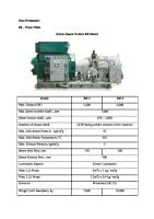
UGT 10000 engine has several modifications including flow path modification for STIG cycle which increases the engine power and reduces NOx emissions level to 25 ppm. UGT 10000S2A engine of “Aquarius” power plant was tested as electric generator drive at “Zorya”“Mashproekt” test facilities. The power plant “Aquarius-16K” with UGT 10000S2A engine was set into experimental and commercial operation in 2003 at Stavishchenskaya compressor station (Kiev region, Ukraine). UGT 10000S2A (DU70) Gas turbine engine
Exhaust Contact condenser
Waste heat recovery boiler
Condensate return Steam pipe Separator Air inlet device
Generator Gas turbine Thermal and sound insulating container
“Aquarius” installation layout
“Aquarius-16K” installation at Stavishchy compressor station
14
Power Plants With UGT 16000
Cycle
Installation
Power, MW
Efficiency
Therm. herm. Electr. T
%
ВТU/kW.h
Fuel consumption
gas (m3 /h)
liquid (kg/h)
Simple UGT 16000
16 300
Co-generation
UGT 16000C
14 500
Combined
UGT16000CC1
18 400
27, 04
Three UGT 16000C units at Kzyll-Orda, Kazakhstan
31,0
11010
5320
4430
79,9
4270
5260
4380
36,2
9430
5260
4280
Two UGT 16000C power units at Mozyr petroleum refinery, Belarus
Floating power station “Aurora borealis” with two UGT 16000C power units
Power station at Salekhard, Russia with one DC59 and two UGT 16000 gas turbines
UGT 16000 is the modernized engine of the 2nd generation. Still it remains popular among the Customers due to its high reliability, easy maintenance and optimal relation between price and quality. Some of the engines have accumulated 80-100 thousand hours without overhaul. Dual fuel version engine is able to switch over from gas to diesel fuel was implemented at Salekhard power station.
15
Power Plants With UGT 15000
Cycle Цикл
Installation Установка
Power, Мощность, MW МВт
Efficiency Эффективность
% %
Electr. Эл. T тепл. Therm. herm. Simple Co-generation Steam-in-gas STIG
UGT 15000
16.0
UGT 15000C
16.0
UGT 15000S2
ВТU/kW.h.h ВТU/kW
Fuel consumption Расход топлива 3 3 gas(м (m газ /ч)/h)
liquid (kg/h) жидкое (кг/ч)
33.5
9740
5020
4215
32.5
10490
4940
4150
25.0
42.0
8120
5960
5020
23,9
“Aquarius”
UGT 15000S2
25.0
42.0
8120
5960
5020
Combined
UGT 15000CC1
22.7
45.3
7530
4940
4150
UGT 15000CC2
45.8
45.9
7430
9880
8300
Assembling of UGT 15000 gas turbine engine
UGT 15000C power unit at Kostyukovichy cement works, Belarus
UGT 15000 in the container
“Aquarius” power station with UGT 15000S2 gas turbine at “Zorya-Mashproekt” testbed
Gas turbine engines of UGT 15000 type are in serial production since 1991. They are used at Navy ships, as gas supercharges drives and electric generators drives for power stations. The serial engine of DG90 modification with operation on natural gas reached NOx emissions level of 37.5 ppm and CO emissions level of 26 ppm. While operating on diesel fuel the decrease of NOx and CO emissions to 25 ppm is achieved by means of steam injection into combustion zone. GTRPC “Zorya-Mashproekt” manufactures and supplies container power stations with UGT 15000 engine.
16
5
Power Plants With UGT 25000
Cycle
Power, MW
Installation
Electr. T Therm. herm. Simple Co-generation Steam-in-gas STIG “Aquarius” Combined
Fuel consumption
Efficiency
%
ВТU/kW.h
gas (m3 /h)
liquid (kg/h)
35,0
9402
7330
6170
34.8
9807
7220
6060
30.8
40
8533
7720
6490
UGT 25000S2 UGT 25000S1
40.7
7974 8533
9570 7720
8020
30.8
42.8 40
UGT 25000S2
40.7
42.8
7974
9570
8020
UGT 25000CC1
34.7
47.5
7185
7220
6060
UGT 25000CC2
70.6
48.5
7037
14440
12120
UGT 25000
25
UGT 25000C
25
UGT 25000S1
35,5
Gas turbine engine UGT 25000 (DG80)
6490
Engine cover during assembling
UGT 25000C power unit during assembling at Beryozovskaya power station, Belarus.
UGT 25000C power unit at Beryozovskaya power station, Belarus.
UGT 25000 is the most powerful from the unified series of engines. It belongs to the forth generation of engines and is in serial production since 1995. It successfully combines the newest attainments of modern design ideas, advanced technologies and many years of experience in operation, which allows produce the high maneuverability and efficiency.
17
Power Plants With UGT 110000
Cycle
Power, MW
Installation
%
Electrical Simple cycle
Combined cycle
Fuel consumption
Efficiency
ВТU/kW.h
gas (m3 /h)
liquid (kg/h)
UGT 110000
110
35,5
9610
31100
26100
UGT 110000CC1 UGT 110000CC2
160 325
51,5 52,5
6758 6563
31810 63620
26700 53400
UGT 110000 at Ivanovskaya power station (Komsomolsk city, Ivanovskaya oblast, Rossia)
1 - Ga turbine engine UGT 110000 2 - Generator TVG-110-2 3 - Air inlet device 4 - Waste heat recovery boiler 5 - Steam turbine 6 - Transformers room
UGT 110000CC2 for Ivanovskaya power station (under construction, Komsomolsk city, Ivanovskaya oblast, Rossia)
UGT 11000CC1 (PGU-160) power units during construction in Kaborga village, Nikolaevskaya oblast, Ukraine
UGT 110000 is a new engine of the fourth generation designed according to single shaft configuration especially to drive the electric generator. The engine favorably differs from foreign analogues in weight which is only 50 tons and overall dimensions: 5.7x3.7x4.0 m. Engine #2 is under trial-commercial operation at Ivanovo power station in Russia. Engine #1 is being mounted now as a part of 160 MWcombined cycle power plant at the company's test plant in Kaborga for further commercial power generation.
UGT 110000 at “Zorya-Mashproekt” test bed
18
5
Power generation applications
TYPE
POWER MW
GTD-1
APPLICATION
LOCATION
NUMBER OF GAS TURBINES
BEGINNING OF OPERATION
REMARKS
YAKUTIYA
FLOATING POWER PLANT
RUSSIA
RAILROAD POWER TRAIN
RUSSIA
CHUKOTKA YAKUTIYA TUMEN REGION BURYATIYA
DO12
KOMI STATIONARY
RUSSIA
KHABAROVSKY KRAY AMUR REGION YAKUTIYA
FLOATING POWER PLANT
RUSSIA
RAILROAD POWER TRAIN
RUSSIA
KHABAROVSKY KRAY PRIMORSRY KRAY YAKUTIYA
2
1971-75
2 2 6 3
1970-74 1978-2000 1986 1976
TUMEN REGION KAZAKHSTAN TENGIZ RUSSIA TUMEN REGION
17 27 4
1980 1990 1998
AZERBAIJAN
13
CHUKOTKA DO14
TUMEN REGION YAKUTIYA KHABAROVSKY KRAY
KAZAKHSTAN STATIONARY
FLOATING POWER PLANT RAILROAD POWER TRAIN STATIONARY FLOATING POWER PLANT RAILROAD POWER TRAIN
DА14
DC59 STATIONARY
YUZHNAYA
RUSSIA
YAKUTIYA
RUSSIA
KHABAROVSKY KRAY YAKUTIYA
RUSSIA RUSSIA RUSSIA
RUSSIA
TURKMENIYA
TUMEN REGION YAKUTIYA SOVETSKAYA GAVAN
NEFTYANYE KAMNI TUMEN REGION
1986
YAKUTIYA
53
1982
NEBIT-DAG
21
1986
9
1980
KAZAKHSTAN JANAJOL
2
1998
TUMEN REGION
2
2002
RUSSIA
RYBINSK
10
1995-2003
Licence
UKRAINE
KHARKOV REGION
1
1997
manufacturing by
CZECH
BRNO, OLOMOUC
2
1994
RUSSIA
STATIONARY
UGT 2500
UGT 6000
CANADA
TORONTO
2
1995
RUSSIA
TUMEN REGION
4
2002-2003
UKRAINE
POLTAVA REGION
1
1999
STATIONARY
UKRAINE
NIKOLAEV REGION
STATIONARY
UKRAINE BELARUS
NIKOLAEV REGION
1 2
1996 2003-2005
STATIONARY
UKRAINE
STATIONARY
UGT 10000
UGT 15000
15
UGT 15000
FLOATING POWER PLANT RAILROAD POWER TRAIN STATIONARY STATIONARY
UGT 16000
UGT 25000 110
NIKOLAEV REGION CHUKOTKA
5
1992
YAKUTIYA
11
1993
RUSSIA
YAKUTIYA
4
1993
RUSSIA
KHABAROVSKY KRAY
2
1992
RUSSIA
BYELORUSSIA MOZYR TUMEN REGION RUSSIA
UKRAINE
UGT 110000
1990
12
2
1991
1
1995
ROSTOV REGION
3
1997
KRASNODARSKY KRAY
3
1992
SEVASTOPOL
3
1992
RUBEJNOYE
1
2003
STATIONARY
UKRAINE BELARUS
NIKOLAEV REGION BREST REGION
1 4
1996 2003-2005
STATIONARY
UKRAINE RUSSIA
NIKOLAEV REGION IVANOVO REGION
1 3
2004 2001-2005
19
“NPO SATURN” not completely included
Nikolaev at night
GTR&PC “Zorya”-“Mashproekt” Oktyabrsky prospekt 42a Nikolaev, 54018, Ukraine. Phone +38 0512 50-25-61, 55-69-92 Fax +38 0512 50-90-50, 55-68-68 E-mail: [email protected], [email protected] http:// www.zmturbines.com
2006