![Varplus M [PDF]](https://pdfs.asia/img/200x200/varplus-m.jpg)
14 0 410 KB
Varplus M LV capacitors from 230V to 690V m o d u l a r i t y s i m p l i c i t y s a f e t y
Get more with the world's Power & Control specialist
A modular range Varplus M capacitors make it easy to cover a wide range in voltage (from 230 V to 690 V) and in power up to 100 kvar from a limited number of references. Power ratings are obtained by: c the use of Varplus M1 or Varplus M4 capacitors alone, c the assembly of several Varplus M1 capacitors, c the assembly of one Varplus M4 capacitor with one or several Varplus M1 capacitors. With these assembly configurations stock management and future power evolution are made very simple.
Configuration examples 400 V 50 Hz + 15 + 15 = 30 kvar
+
+ 15 + 12,5 + 12,5 = 40 kvar
+ 60 + 15 = 75 kvar
+
+ 50 + 15 + 15 = 80 kvar
+
+
+ 60 + 15 + 12,5 + 12,5 = 100 kvar
Varplus M1
Varplus M4
Safety of personnel and installations c the technology of Varplus M capacitors is based on the use of self healing polypropylene film requiring no gas or liquid impregnation.
HRC fuse Metallic disc
Overpressure disconnect device
c the HQ protection system integrated into each capacitor element provides total safety. A unique design, patented, it has been used for more than 10 years on several million elements. c the HQ protection system provides protection against the two fault types met in capacitor end of life. Protection against high current faults is provided by an HRC cartridge fuse. Protection against low current faults is provided by the combination of an overpressure disconnect device and the HRC fuse. c whatever the fault pressure inside the capacitor element is always limited to a value far lower than the maximum admissible pressure. c in both fault types the electrical current is always opened by a standard HRC fuse.
Cross-section of a capacitor element
c the plastic enclosure of Varplus M capacitors offer double electrical insulation. Plastic materials used provide both excellent mechanical properties and maximum self extinguishing ratings (UL 94 5 VB certification).
Simplicity of mounting and connection c the design of Varplus M capacitors meets key principles of LV electrical distribution products to which they are associated in electrical switchboards: simple assembly on vertical plate, fast connection on power terminals. c their simplicity can be found in the ergonomic design details: standardized dimensions, front or rear connection, simple and original finger contact protection, IP 42 protection with the addition of a cable entry box.
Connection
c their ingenious design allows the total occupied volume to be very compact and eases the cooling of elements. c the use of functional plates makes it easy to standardize the installation of capacitors in panels and to simplify the maintenance of power factor correction equipment.
Varplus M4
Front connection
Rear connection
Varplus M1
Front connection
Accessories
Rear connection
Varplus M1
ref. 52461 front connection
ref. 52460 front connection
ref. 52462 front connection
ref. 52464 front connection
Varplus M4
I
CERT
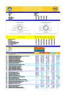
Capacitor references and ratings (kvar) 50 Hz Varplus M1 Varplus M1 Varplus M1 Varplus M1 Varplus M1 Varplus M4 Varplus M4
230 V 2,5 3,8 5 5,5 7,5 30 32,5 50 Hz
240 V 2,5 4 5,5 6 8,5 33 35
230 V 3 4,5 6 7 9,5 36 40 60 Hz
240 V 3 5 6,5 7,5 10 40 42,5
Varplus M1 Varplus M1 Varplus M1 Varplus M1 Varplus M1 Varplus M4 Varplus M4
400 V 5 7,5 10 12,5 15 50 60 50 Hz
415 V 5 7,5 10 12,5 15 50 65
400 V 5,5 9 12,5 15 18 60 70 60 Hz
415 V 6 9 13,5 16 19,5 60 75
440 V 4,5 7 9 12,5 14 50 55
470 V 5 8 10 14,5 16 57,5 60
440 V 5 8,5 10 15 17 60 65
470 V 6 9,5 12 17 19 69,5 75
Varplus M1 Varplus M1 Varplus M1 Varplus M1 Varplus M1 Varplus M4 Varplus M4
60 Hz
Ø7
218
210
95,5
M8 116
Varplus M1
210
Y
T
L
I
480 V / 525 V
50 Hz
50/60 Hz 52431 52432 52433 52434 52435 52436 550 V / 590 V
Varplus M1 Varplus M1 Varplus M1 Varplus M1 Varplus M4 Varplus M4
480 V 5 8 10 12,5 40 50 50 Hz
525 V 6 10 12,5 15 50 60
480 V 6 10 12,5 15 50 60 60 Hz
525 V 7,5 12,5 15 18 60 70
50/60 Hz 52437 52438 52439 52440 52441 600 V / 690 V
Varplus M1 Varplus M1 Varplus M1 Varplus M4 Varplus M4
550 V 5,5 10 12,5 40 50 50 Hz
590 V 6 12,5 14,5 50 58
550 V 6,5 12,5 15 50 60 60 Hz
590 V 7,5 15 17 60 70
600 V 2,5 5 8 10 33 40
690 V 3,5 7 11 14 45 55
600 V 3 6,5 10 12,5 40 50
690 V 4 8,5 13 16,5 50 66
50/60 Hz 52442 52443 52444 52445 52446 52447
Varplus M1 Varplus M1 Varplus M1 Varplus M1 Varplus M4 Varplus M4
60 Hz
Options
Ø6,5x13
M8
218 192
192
Ø7
IS0O01 QUA
50/60 Hz 52410 52411 52412 52413 52414 52415 52416 400 V / 415 V
50/60 Hz 52424 52425 52426 52427 52428 52429 52430
T CA ION
9
230 V / 240 V
50/60 Hz 52417 52418 52419 52420 52421 52422 52423 440 V / 470 V
FI
83 95,5
325 350
Varplus M4
finger contact protection réf. set of 3 terminal covers for Varplus M1 - front connection 52461 set of 3 terminal covers for Varplus M1 - rear connection 52466 set of 3 terminal covers for Varplus M4 front connection or rear connection 52462 set of 3 terminal covers for Varplus M4 rear connection with special cable lug 52463 IP 42 protection three phase cable entry box for Varplus M1 52460 three phase cable entry box for Varplus M4 52464 IP 54 protection on request
Technical specifications standards tolerance on capacitance values losses insulation level
IEC 60831-1 and 2, NF C 54-104, VDE 0560 Teil 41, CSA 22-2 N° 190 0, +10% i 0.7 W/kvar discharge resistors included 50 Hz 1 min withstand voltage: 6 kV impulse wave withstand: 1.2 / 50 µs – 25 kV if the rear panel is at least 15 mm away from all metal frames – 11 kV if the rear panel is up against a metal frame
M1+M1 assembly front connection M1+M1 assembly rear connection M4+M1 assembly(*) rear or front connection
230/240 V 30 kvar 15 kvar 60 kvar
400/415 V 60 kvar 30 kvar 100 kvar
440/470 V 60 kvar 30 kvar 100 kvar
480/525 V 60 kvar 30 kvar 100 kvar
550/590 V 60 kvar 30 kvar 100 kvar
600/690 V 60 kvar 30 kvar 100 kvar
temperature class max
-25/D -25/C -25/B admissible current overloads admissible voltage overloads (8 h in 24 h specifed by IEC 831 1 and 2) colors weight
55°C 50°C 45°C 30% 10%
highest average over all period of: 24 hours 1 year 45°C 35°C 40°C 30°C 35°C 25°C
reactive power (kvar) 230/240 V up to 40 kvar 41 to 50 51 to 60
400/415 V 440/470 V 480/525 V 550/590 V 600/690 V up to 65 kvar up to 76 kvar up to 85 kvar up to 100 kvar up to 100 kvar 67.5 to 90 77 to 100 85 to 100 92.5 to 100
base: RAL 9002 - elements: RAL 9005 - terminal covers: RAL 9002 Varplus M1: 2.6 kg - Varplus M4: 10 kg
* using Varplus M4 power termination
Schneider Electric Industries SA Rectiphase BP10 74371 Pringy cedex France Tel.: (33) 04 50 66 95 00 Fax: (33) 04 50 27 24 19 ART 74530
As standards, specifications and design develop from time to time, always ask for confirmation of the information given in this publication. This document has been printed on ecological paper Design: Studio Insign' - AMEG Publishing: Schneider Electric Printing: Colorpress - 1000 ex.
01-2002
CFIED196028EN © 2002 Schneider Electric - All right reserved
maximum assembly configurations (kvar)