![ZXSDR A8602 Product Description (RRU Imacro) [PDF]](https://pdfs.asia/img/200x200/zxsdr-a8602-product-description-rru-imacro.jpg)
4 0 466 KB
ZXSDR A8602 Product Description UniRAN 16/UL Multi-Mode
ZXSDR A8602 Product Description
ZXSDR A8602 Product Description Version
Date
Author
V1.00
2017/01/26
Yang Lisha
V1.10
2017/05/11
Yang Lisha
Reviewer
Notes Update 256QAM in LTE downlink 1.
Introduce DC power supply
2.
Delete S1800 module
© 2017 ZTE Corporation. All rights reserved. ZTE CONFIDENTIAL: This document contains proprietary information of ZTE and is not to be disclosed or used without the prior written permission of ZTE. Due to update and improvement of ZTE products and technologies, information in this document is subjected to change without notice.
ZTE Confidential & Proprietary
1
ZXSDR A8602 Product Description
TABLE OF CONTENTS
2
1 1.1 1.2 1.3
Overview ............................................................................................................ 4 Introduction .......................................................................................................... 4 Benefits................................................................................................................ 4 Application Scenarios .......................................................................................... 5
2 2.1 2.2 2.2.1 2.2.2 2.2.3 2.2.4 2.2.5 2.3 2.4
Product Architecture ......................................................................................... 5 Physical Appearance ........................................................................................... 5 Hardware Architecture ......................................................................................... 6 DTR & PA ............................................................................................................ 7 DFL ...................................................................................................................... 8 PWR .................................................................................................................... 8 OIB ...................................................................................................................... 8 Electrical Tilt Antenna .......................................................................................... 8 Software Architecture ........................................................................................... 8 Functionality......................................................................................................... 9
3 3.1 3.2 3.2.1 3.2.2 3.2.3 3.2.4 3.3 3.4 3.4.1 3.4.2 3.5 3.6 3.7 3.8 3.9
Technical Specifications ................................................................................. 10 Physical Specifications....................................................................................... 10 Performance Specifications ............................................................................... 10 Operation Frequency Band ................................................................................ 10 ToC Output Power ............................................................................................. 11 Capacity ............................................................................................................. 11 Static Receiving Sensitivity ................................................................................ 11 Antenna Specifications ...................................................................................... 12 Power Specifications.......................................................................................... 12 Power Requirements ......................................................................................... 12 Power Consumption........................................................................................... 13 Interface Specifications ...................................................................................... 13 Transmission ..................................................................................................... 14 Working Environment Specifications .................................................................. 14 Electromagnetic Compatibility Specifications ..................................................... 14 Reliability Specifications..................................................................................... 15
4
Glossary ........................................................................................................... 16
ZTE Confidential & Proprietary
ZXSDR A8602 Product Description
FIGURES Figure 2-1 Appearance ....................................................................................................... 6 Figure 2-2 System Structure ............................................................................................... 6 Figure 2-3 Software Architecture......................................................................................... 9
TABLES Table 3-1 Physical Specifications.......................................................................................10 Table 3-2 Operation Frequency Band ................................................................................11 Table 3-3 ToC Output Power .............................................................................................11 Table 3-4 Capacity .............................................................................................................11 Table 3-5 Receiver Sensitivity ............................................................................................12 Table 3-6 Antenna Specifications.......................................................................................12 Table 3-7 Power Supply .....................................................................................................12 Table 3-8 Power Consumption ...........................................................................................13 Table 3-9 Description of A8602 External Interfaces ...........................................................13 Table 3-10 CPRI Interfaces................................................................................................14 Table 3-11 Environment Specifications ..............................................................................14 Table 3-12 Electromagnetic Compatibility Specifications ...................................................14 Table 3-13 Reliability Characteristics .................................................................................15
ZTE Confidential & Proprietary
3
ZXSDR A8602 Product Description
1
Overview
1.1
Introduction ZTE ZXSDR A8602 (hereinafter A8602) is the latest released ultra broadband active antenna unit from ZTE. It consists of remote unit and electrical tilt antenna, supporting UMTS and LTE telecommunication systems. A8602 is superior in many aspects in active antenna solution, ultra wide-band technology and dynamic output power sharing function. Compared with traditional solution, the RF module is integrated into antenna by active antenna solution. In this way, the feeder loss is saved and the installation space is greatly reduced on the tower, on the pole or against the wall. The document is designed to give an overview of the characteristics of A8602 M1821, its key benefits, the architecture, functionality and services, as well as the system capabilities.
1.2
Benefits
Integration of Antenna, Simplification of RAN Architecture A8602 is integrated with remote radio unit and electrical tilt antenna. With this design, the feeder connection between radio unit and antenna is removed and feeder loss is saved. The combination also saves the dwindling installation resources on the tower, on the pole or against the wall.
Ultra Broadband, High Integration, Less Modules A8602 M1821 supports ultra band of 365MHz, from 1805MHz to 2170MHz. When there are network construction or reconstruction requirements both in 1800MHz and 2100MHz, one A8602 replaces two traditional RRUs with one in 1800MHz and the other in 2100MHz. It greatly reduces module quantities and saves installation space.
4
ZTE Confidential & Proprietary
ZXSDR A8602 Product Description
Multi-Mode RRU, Smooth Evolution A8602 M1821 supports LTE in 1800MHz and UMTS and LTE in 2100MHz. In different phases during the evolution process towards LTE, Operators can find the most appropriate configuration of A8602 through software upgrade to suit the frequency spectrum holdings.
Slim and Light, Suitable for Macro Coverage in Streets At 17kg and 17L in slim columnar shape, A8602 requires less installation space. It is easy to be installed in the streets in the dense urban area. After the network coverage has been almost completed in dense area, the newly arisen issues should be considered to improve the user experience, such as capacity expansion and blind spot coverage in the streets between tall buildings. A8602 with 2*40W output power and small size, is the appropriate choice for operators in the scenarios mentioned above.
1.3
Application Scenarios A8602 and Baseband Unit (BBU) comprise the distributed macro base station BS8700.
2
Product Architecture
2.1
Physical Appearance The physical appearances of A8602 are shown in the following figure.
ZTE Confidential & Proprietary
5
ZXSDR A8602 Product Description
Figure 2-1
2.2
Appearance
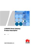
Hardware Architecture The hardware architecture of A8602 is shown in Figure 2-2.
Figure 2-2
System Structure
A8602 ANT1
TX1 TX2
CPRI 1
OIB
CPRI 2
DTR & PA RX1 RX2
Antenna
DFL ANT2
PWR AISG
A8602 includes 5 main hardware modules.
6
ZTE Confidential & Proprietary
ZXSDR A8602 Product Description
Dual-channel Transceiver & Power Amplifier (DTR & PA)
Optical interface board (OIB)
Duplex Filter (DFL)
Power module (PWR)
Electrical Tilt Antenna
Functions of each module are specified below.
2.2.1
DTR & PA The DTR has following functions:
Processing of 2 received signals and 2 transmitted signals;
Radio signal up/down conversion;
Downlink IQ signal multiplexing and uplink signal de-multiplexing;
Signal amplifying, filtering, A/D conversion and D/A conversion;
Conversion between optical and electric signal;
Capture of reference clock signal from baseband unit and distribution of clock signal to other units;
Voltage Standing Wave Ratio (VSWR) measurement and report;
Hardware failure self-detection and alarm;
Over-heat detection and alarm;
Provision of communication interfaces: 2 CPRI interfaces;
Reset function;
Radio signal amplifying function;
ZTE Confidential & Proprietary
7
ZXSDR A8602 Product Description
2.2.2
Temperature report function;
Over-current, over-heat, over-power and over-standing wave protection function.
DFL The DFL has following functions:
2.2.3
Combination and isolation of transmitted and received signals;
Filtering of the transmitted signal and received signal.
PWR The PWR has following functions:
-48VDC or 220VAC power supply input;
Monitoring of input over-voltage/under-voltage, input power outage, output over-voltage/under-voltage, output over-current alarm, and reporting to DTR & PA board.
2.2.4
OIB Optical interface board provides two ways of optical-electrical conversion in the CPRI interface.
2.2.5
Electrical Tilt Antenna Transmission and reception of radio frequency signal.
2.3
Software Architecture The software architecture of A8602 can be divided into two layers: SDR Unified Platform Software and Application Software. The architecture is shown in the following figure.
8
ZTE Confidential & Proprietary
ZXSDR A8602 Product Description
Figure 2-3
Software Architecture
Application
OAM
Software
OSS
SDR Unified Platform
Linux
BSP
Hardware
Software
Hardware System
The Operating and Maintenance (OAM) sub-system is the application layer. Its main functions are software downloading, configuration, management, system maintenance and measurement. The Operation Support Sub-system (OSS) is the supporting layer in this entire framework. It is a hardware independent layer that provides basic functions such as scheduling, timer, and memory management, communication, sequencing control, monitoring, alarming and logging. The Board Support Package (BSP) provides device driver & initialization and supports basic functions like alarming and monitoring. It also provides the related interfaces and services to the Operating System.
2.4
Functionality A8602 is the remote radio unit of distributed base station. The signal is transmitted /received through A8602 to/from base band processing unit for further processing via standard CPRI interface. By applying the distributed system, the feeder loss will be eliminated when the radio unit is positioned close to the antenna. The coverage is enlarged with this solution.
ZTE Confidential & Proprietary
9
ZXSDR A8602 Product Description
A8602 supports the following functionalities:
Supports 1800M&2100MHz of operation bands by M1821 module
Supports 2T2R in one box
Support 256QAM modulation in LTE downlink and 64QAM in uplink
Supports transmit power report function for every carrier
Supports overload protection function for power amplifier
Supports transmit channel switching on/off function
Supports no affection to the running of BBU and other RRUs that connected to it in case of failure
3
Technical Specifications
3.1
Physical Specifications Table 3-1
Physical Specifications Item
Specification
Size (H*W*D) (mm)
770*170*150 mm (17L)
Weight (kg)
17kg
Color
Silver gray
3.2
Performance Specifications
3.2.1
Operation Frequency Band
10
ZTE Confidential & Proprietary
ZXSDR A8602 Product Description
Table 3-2
Operation Frequency Band Type
Operation Radio Frequency Band
A8602 M1821
3.2.2
Uplink:1710 – 1785 MHz,
Downlink:1805 – 1880 MHz
Uplink:1920 – 1980 MHz,
Downlink:2110 – 2170 MHz
ToC Output Power Table 3-3
ToC Output Power Type
TOC Output Power
A8602 M1821
2*40W
Note: The TOC here means the max capability of the hardware. The specific TOC output power is limited by the license.
3.2.3
Capacity A8602 M1821 supports LTE in band 3 (1800MHz) and UMTS/LTE in band 1 (2100MHz) in the same time. It works in UMTS and LTE mode through software configuration. The maximum RRU configurations in different modes are listed below and capacities of cells in one row are supported simultaneously.
Table 3-4
Capacity
RRU
A8602 M1821
3.2.4
[email protected]
[email protected]
[email protected]
(2*2 MIMO cell)
(non-MIMO carrier)
(2*2 MIMO cell)
1
4
1
Static Receiving Sensitivity The static receiving sensitivity of A8602 is shown as following table.
ZTE Confidential & Proprietary
11
ZXSDR A8602 Product Description
Table 3-5
Receiver Sensitivity
Mode
Frequency Spectrum(MHz)
3.3
Single Antenna (dBm)
Dual Antennas (dBm)
UMTS
2100
-126.5
-129.2
LTE
1800/2100
-106.4
-109.2
Antenna Specifications Table 3-6
Antenna Specifications Antenna Index
Specification
Frequency Range (MHz)
1710~2170
Gain (dBi)
15
Polarization(°)
±45
Half - power Horizontal Beam width(°)
65±5
Half - power Vertical Beam width(°)
14±1
Electrical Tilt(°)
-2 - +12
Front to Back Ratio(dB)
≥25
Isolation (dB)
≥25
Impedance (Ω)
50
Lightning protection
Direct Ground
3.4
Power Specifications
3.4.1
Power Requirements The following table describes the power supply and the fluctuation range.
Table 3-7
Power Supply Item
Power Supply
12
Specification DC: -48V (-37V – -60V) AC: 220V (176V – 264V)
ZTE Confidential & Proprietary
ZXSDR A8602 Product Description
3.4.2
Power Consumption Power consumption of A8602 M1821 depends on its configuration. The value is given in the typical configuration.
Table 3-8
Power Consumption
Configuration
Typical PC (W)
1L(1.8GHz)+4U(2.1GHz), 2*20W/L,10W/U, total: 2*40W
3.5
Peak PC (W)
270 (DC)
370 (DC)
280 (AC)
380 (AC)
Interface Specifications A8602 provides four external interfaces, including power supply, grounding cable interface and two CPRI interfaces. The description of interface types and connectors is listed below.
Table 3-9 No.
Description of External Interfaces Label
Interface
Interface Type/Connector
Interface for communication 1
OPT1
between the RRU and a BBU,
LC-type optical interface (IEC 874)
or RRU cascading interface 2
OPT2
RRU cascading interface
3
PWR
Power input interface
4
Grounding cable interface
LC-type optical interface (IEC 874) DC power connector AC power connector -
Additionally, A8602 provides 4 LED indicators. The indicators on the A8602 panel indicate the operating status of the RRU.
ZTE Confidential & Proprietary
13
ZXSDR A8602 Product Description
3.6
Transmission A8602 is connected to BBU through CPRI interfaces. The following table lists more information about CPRI interfaces.
Table 3-10
CPRI Interfaces
Item
Value
CPRI interface
3.7
2
Interface Type SFP (LC)
Speed 10Gbps
[1]
Standard CPRI V5.0
Working Environment Specifications Table 3-11
Environment Specifications Item
Specification
Temperature
-40 to +55 °C
Relative Humidity
5% to 100%
Waterproof/Dustproof
IP65 ≤5 Ω; earth resistance can be less than 10 Ω in
Ground
thunder-less area where thunderstorm days is less than 20 per year.
3.8
Electromagnetic Compatibility Specifications Table 3-12
Electromagnetic Compatibility Specifications Item
Static Discharge Immunity
Specification Contact Discharge: ±6000V Air Discharge: ±8000V
1
The speed here refers to the max capability of the hardware. The specific speed depends on the optical module configuration.
14
ZTE Confidential & Proprietary
ZXSDR A8602 Product Description
3.9
Reliability Specifications Table 3-13
Reliability Characteristics Item
MTBF
Specification ≥300,000 hours (AC) ≥310,000 hours (DC)
MTTR
1 hour
Availability index
≥99.999667% (AC) ≥99.999677% (DC)
Down duration
≤1.752 min/year (AC) ≤1.695 min/year (DC)
ZTE Confidential & Proprietary
15
ZXSDR A8602 Product Description
4
Glossary Abbreviations
16
Full Characteristics
BBU
Base Band processing Unit
BSP
Board Support Package
CPRI
Common Public Radio Interface
DL
Downlink
DFL
Duplexer & Filters
DPD
Digital Pre-Distortion
LMT
Local Maintenance Terminal
LNA
Low-Noise-Amplifier
LTE
Long Term Evolution
MCPA
Multi-Carrier Power Amplifier
MIMO
Multi Input Multi Output
MTBF
Mean Time Between Failures
MTTR
Mean Time To Recovery
OAM
Operating And Maintenance
OSS
Operation Support Sub-system
PA
Power Amplifier
PWR
Power
DTR
Dual-channel Transceiver
RF
Radio Frequency
RRU
Remote Radio Unit
SDR
Software Defined Radio
ToC
Top of Cabinet
UL
Uplink
VSWR
Voltage Standing Wave Ratio
ZTE Confidential & Proprietary