![2015-2017 Service Manual Yzf-R1 [PDF]](https://pdfs.asia/img/200x200/2015-2017-service-manual-yzf-r1.jpg)
5 0 66 MB
2015 SERVICE MANUAL
YZF-R1 YZF-R1F YZF-R1M YZF-R1MF
2CR-28197-E0
EAS20002
YZF-R1/YZF-R1F YZF-R1M/YZF-R1MF SERVICE MANUAL ©2015 by Yamaha Motor Co., Ltd. First edition, February 2015 All rights reserved. Any reproduction or unauthorized use without the written permission of Yamaha Motor Co., Ltd. is expressly prohibited.
EAS20003
IMPORTANT This manual was produced by the Yamaha Motor Company, Ltd. primarily for use by Yamaha dealers and their qualified mechanics. It is not possible to include all the knowledge of a mechanic in one manual. Therefore, anyone who uses this book to perform maintenance and repairs on Yamaha vehicles should have a basic understanding of mechanics and the techniques to repair these types of vehicles. Repair and maintenance work attempted by anyone without this knowledge is likely to render the vehicle unsafe and unfit for use. Yamaha Motor Company, Ltd. is continually striving to improve all of its models. Modifications and significant changes in specifications or procedures will be forwarded to all authorized Yamaha dealers and will appear in future editions of this manual where applicable. TIP Designs and specifications are subject to change without notice. EAS30001
IMPORTANT MANUAL INFORMATION Particularly important information is distinguished in this manual by the following notations. This is the safety alert symbol. It is used to alert you to potential personal injury hazards. Obey all safety messages that follow this symbol to avoid possible injury or death. WARNING
A WARNING indicates a hazardous situation which, if not avoided, could result in death or serious injury.
NOTICE
A NOTICE indicates special precautions that must be taken to avoid damage to the vehicle or other property.
TIP
A TIP provides key information to make procedures easier or clearer.
EAS20004
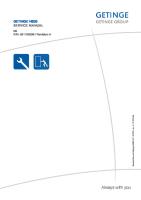
HOW TO USE THIS MANUAL This manual is intended as a handy, easy-to-read reference book for the mechanic. Comprehensive explanations of all installation, removal, disassembly, assembly, repair and check procedures are laid out with the individual steps in sequential order. • The manual is divided into chapters and each chapter is divided into sections. The current section title “1” is shown at the top of each page. • Sub-section titles “2” appear in smaller print than the section title. • To help identify parts and clarify procedure steps, there are exploded diagrams “3” at the start of each removal and disassembly section. • Numbers “4” are given in the order of the jobs in the exploded diagram. A number indicates a disassembly step. • Symbols “5” indicate parts to be lubricated or replaced. Refer to “SYMBOLS”. • A job instruction chart “6” accompanies the exploded diagram, providing the order of jobs, names of parts, notes in jobs, etc. This step explains removal and disassembly procedure only. For installation and assembly procedure, reverse the steps. • Jobs “7” requiring more information (such as special tools and technical data) are described sequentially.
CLUTCH
CLUTCH
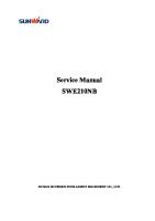
housing dogs or replace the clutch housing. TIP Pitting on the clutch housing dogs will cause erratic clutch operation.
EAS20055
CLUTCH
Clutch plate “1” Part No.
Removing the clutch cover
Thickness
2CR-16325-10
2.0 mm (0.079 in)
2CR-16325-00
2.3 mm (0.091 in)
2CR-16325-20
2.6 mm (0.102 in)
STD
1
5
2. Check: • Bearing Damage/wear → Replace the bearing and clutch housing.
4
EAS30353 EAS30351
2 3 7 Nm (0.7 m • kgf, 5.1 ft • lbf)
1 (10) 1st T.R .
*
2nd
FW
6 Nm (0.6 m • kgf, 4.3 ft • Ibf) 3.0 Nm (0.30 m • kgf, 2.2 ft • Ibf) Specified angle 90°
D
CHECKING THE CLUTCH SPRINGS The following procedure applies to all of the clutch springs. 1. Check: • Clutch spring Damage → Replace the clutch springs as a set. 2. Measure: • Clutch spring free length “a” Out of specification → Replace the clutch springs as a set. Clutch spring free length 47.36 mm (1.86 in) Limit 44.99 mm (1.77 in)
Following the tightening order, loosen the bolt one byone, and then retighten it to the specific torque. Order
Job/Parts to remove
Q’ty
Front side cowling (right) Engine oil 1 2 3 4 5
Clutch cable Clutch cover Clutch cover gasket Dowel pin Oil filler cap
1 1 1 2 1
CHECKING THE CLUTCH BOSS 1. Check: • Clutch boss splines Damage/pitting/wear → Replace the clutch boss. TIP Pitting on the clutch boss splines will cause erratic clutch operation.
Remarks Refer to “GENERAL CHASSIS (2)” on page 4-7. Drain. Refer to “CHANGING THE ENGINE OIL” on page 3-30. Disconnect.
EAS30354
CHECKING THE PRESSURE PLATE 1. Check: • Pressure plate 1 “1” • Pressure plate 2 “2” Cracks/damage → Replace. • Bearing “3” Damage/wear → Replace. EAS30352
CHECKING THE CLUTCH HOUSING 1. Check: • Clutch housing dogs Damage/pitting/wear → Deburr the clutch
5-53
5-58
EAS20005
SYMBOLS The following symbols are used in this manual for easier understanding. TIP The following symbols are not relevant to every vehicle. SYMBOL
DEFINITION
SYMBOL
Serviceable with engine mounted
DEFINITION Gear oil
G Filling fluid
Molybdenum disulfide oil
M Lubricant
Brake fluid
BF
B
Wheel bearing grease
Tightening torque
LS
Lithium-soap-based grease
Wear limit, clearance
M
Molybdenum disulfide grease
Engine speed
S
Silicone grease
T.
Special tool
R.
Electrical data
Engine oil
E Silicone fluid
S
LT
New
Apply locking agent (LOCTITE®).
Replace the part with a new one.
EAS10003
TABLE OF CONTENTS GENERAL INFORMATION
1
SPECIFICATIONS
2
PERIODIC CHECKS AND ADJUSTMENTS
3
CHASSIS
4
ENGINE
5
COOLING SYSTEM
6
FUEL SYSTEM
7
ELECTRICAL SYSTEM
8
TROUBLESHOOTING
9
GENERAL INFORMATION IDENTIFICATION..............................................................................................1-1 VEHICLE IDENTIFICATION NUMBER ......................................................1-1 MODEL LABEL...........................................................................................1-1 FEATURES .......................................................................................................1-2 OUTLINE OF THE FI SYSTEM..................................................................1-2 FI SYSTEM.................................................................................................1-3 YCC-T (Yamaha Chip Controlled Throttle)/YCC-I (Yamaha Chip Controlled Intake) ..............................................................1-5 ELECTRONIC CONTROL-RELATED FEATURES....................................1-8 OUTLINE OF THE UBS ...........................................................................1-13 OUTLINE OF THE ABS............................................................................1-17 ABS COMPONENT FUNCTIONS ............................................................1-22 UBS AND ABS OPERATION ...................................................................1-26 ABS WARNING LIGHT AND OPERATION..............................................1-30 ABS AND UBS FUNCTION......................................................................1-31 GLOSSARY..............................................................................................1-32 DISPLAY ..................................................................................................1-32 MENU SCREEN .......................................................................................1-36 IMPORTANT INFORMATION .........................................................................1-48 PREPARATION FOR REMOVAL AND DISASSEMBLY..........................1-48 REPLACEMENT PARTS..........................................................................1-48 GASKETS, OIL SEALS AND O-RINGS ...................................................1-48 ALUMINUM BOLTS..................................................................................1-48 LOCK WASHERS/PLATES AND COTTER PINS ....................................1-49 BEARINGS AND OIL SEALS ...................................................................1-49 CIRCLIPS .................................................................................................1-49 RUBBER PARTS......................................................................................1-49 BASIC SERVICE INFORMATION ..................................................................1-50 QUICK FASTENERS................................................................................1-50 ELECTRICAL SYSTEM............................................................................1-51 SPECIAL TOOLS ...........................................................................................1-56
1 2 3 4 5 6 7 8 9
IDENTIFICATION EAS20007
IDENTIFICATION EAS30002
VEHICLE IDENTIFICATION NUMBER The vehicle identification number “1” is stamped into the right side of the steering head pipe.
1
EAS30003
MODEL LABEL The model label “1” is affixed to the frame under the passenger seat. This information will be needed to order spare parts.
1
1-1
FEATURES EAS20008
FEATURES EAS30005
OUTLINE OF THE FI SYSTEM The main function of a fuel supply system is to provide fuel to the combustion chamber at the optimum air-fuel ratio in accordance with the engine operating conditions and the atmospheric temperature. In the conventional carburetor system, the air-fuel ratio of the mixture that is supplied to the combustion chamber is created by the volume of the intake air and the fuel that is metered by the jet used in the respective carburetor. Despite the same volume of intake air, the fuel volume requirement varies by the engine operating conditions, such as acceleration, deceleration, or operating under a heavy load. Carburetors that meter the fuel through the use of jets have been provided with various auxiliary devices, so that an optimum airfuel ratio can be achieved to accommodate the constant changes in the operating conditions of the engine. As the requirements for the engine to deliver more performance and cleaner exhaust gases increase, it becomes necessary to control the air-fuel ratio in a more precise and finely tuned manner. To accommodate this need, this model has adopted an electronically controlled fuel injection (FI) system, in place of the conventional carburetor system. This system can achieve an optimum air-fuel ratio required by the engine at all times by using a microprocessor that regulates the fuel injection volume according to the engine operating conditions detected by various sensors. The adoption of the FI system has resulted in a highly precise fuel supply, improved engine response, better fuel economy, and reduced exhaust emissions.
14.IMU (Inertial Measurement Unit) 15.Battery 16.Fuel pump 17.O2 sensor 18.Coolant temperature sensor 19.Crankshaft position sensor 20.ECU (Engine Control Unit) 21.Spark plug 22.Ignition coil 23.Cylinder identification sensor
1. Intake air temperature sensor 2. Engine trouble and system warning light 3. Atmospheric pressure sensor 4. Air induction system solenoid 5. Intake funnel servo motor 6. Secondary injector 7. Accelerator position sensor 8. Throttle servo motor 9. Intake air pressure sensor 10.Throttle position sensor 11.Primary injector 12.EXUP servo motor 13.Rear wheel sensor
1-2
FEATURES EAS30617
FI SYSTEM The fuel pump delivers fuel to the fuel injector via the fuel filter. The pressure regulator maintains the fuel pressure that is applied to the fuel injector at a certain level. Accordingly, when the energizing signal from the ECU energizes the fuel injector, the fuel passage opens, causing the fuel to be injected into the intake manifold only during the time the passage remain open. Therefore, the longer the length of time the fuel injector is energized (injection duration), the greater the volume of fuel that is supplied. Conversely, the shorter the length of time the fuel injector is energized (injection duration), the lesser the volume of fuel that is supplied. The injection duration and the injection timing are controlled by the ECU. Signals that are input from the throttle position sensor, accelerator position sensor, coolant temperature sensor, atmospheric pressure sensor, cylinder identification sensor, IMU (Inertial Measurement Unit), crankshaft position sensor, intake air pressure sensor, intake air temperature sensor, rear wheel sensor and O2 sensor enable the ECU to determine the injection duration. The injection timing is determined through the signals from the crankshaft position sensor. As a result, the volume of fuel that is required by the engine can be supplied at all times in accordance with the driving conditions.
1-3
FEATURES Illustration is for reference only.
C. Control system
1. Secondary injector 2. Fuel pump 3. Primary injector 4. Cylinder identification sensor 5. ECU (Engine Control Unit) 6. Throttle position sensor 7. Accelerator position sensor 8. Rear wheel sensor 9. Intake air temperature sensor 10.IMU (Inertial Measurement Unit) 11.O2 sensor 12.Catalytic converter 13.Coolant temperature sensor 14.Crankshaft position sensor 15.Intake air pressure sensor 16.Throttle servo motor 17.Throttle body 18.Atmospheric pressure sensor 19.Air filter case 20.Intake funnel servo motor A. Fuel system B. Air system
1-4
FEATURES EAS30713
YCC-T (Yamaha Chip Controlled Throttle)/YCC-I (Yamaha Chip Controlled Intake) Mechanism characteristics Yamaha developed the YCC-T and YCC-I system employing the most advanced electronic control technologies. Electronic control throttle systems have been used on automobiles, but Yamaha has developed a faster, more compact system specifically for the needs of a sports motorcycle. The Yamahadeveloped system has a high-speed calculating capacity that produces computations of running conditions every 1/1000th of a second. The YCC-T system is designed to respond to the throttle action of the rider by having the ECU instantaneously calculate the ideal throttle valve opening and generate signals to operate the motor-driven throttle valves and thus actively control the intake air volume. The YCC-I system calculates the value from the engine speed and throttle opening rate, activates the intake air funnel with the electronic control motor drive to control the intake pipe length in order to gain the high power output in all revolution ranges from low speeds to high speeds. Aims and advantages of using YCC-T system • Increased engine power By shortening the air intake path, higher engine speed is possible Increased engine power. • Improved driveability Air intake volume is controlled according to the operating conditions Improved throttle response to meet engine requirement. Driving force is controlled at the optimal level according to the transmission gear position and engine speed Improved throttle control. • Engine braking control Due to the throttle control, optimal engine braking is made possible. • Simplified idle speed control (ISC) mechanism The bypass mechanism and ISC actuator are eliminated A simple mechanism is used to maintain a steady idle speed. • Reduced weight Compared to using a sub-throttle mechanism, weight is reduced.
1 1 A 2 4 3 1. 2. 3. 4.
Throttle valve Throttle position sensor Throttle servo motor Accelerator position sensor
A. To throttle grip
1-5
FEATURES Aims and advantages of using YCC-I system • Improved power band By using a dual intake funnel system, YCC-I optimizes the effectiveness of the fuel injection system to deliver an incredibly precise air/fuel mixture to the combustion chamber. This degree of intake volume control gives both improved low to mid-range power, as well as improved power in the higher rpm range. In effect, the YCC-I offers higher levels of power across the RPM range. • Electronically controlled intake length The YCC-I system consists of four lightweight plastic resin funnels, and each of these is divided into an upper and lower portion. Depending upon operating conditions, the funnels can be joined to form a single long funnel, or split to create a short funnel. This change is performed instantaneously by an electrically controlled servo-motor which handles the function so smoothly that the rider is unaware it is happening.
A. Down position (long intake) (Low rpm to Mid rpm) B. Up position (short intake) (High rpm)
1-6
FEATURES YCC-T/YCC-I system outline
3 2 1 4
5 6 7 8 9 10
11 1. Throttle position sensor 2. Throttle servo motor 3. Accelerator position sensor 4. ECU (Engine Control Unit) 5. Sensor input 6. Neutral switch 7. Crankshaft position sensor 8. Rear wheel sensor 9. Coolant temperature sensor 10.Atmospheric pressure sensor 11.Intake funnel servo motor
1-7
FEATURES EAS31625
ELECTRONIC CONTROL-RELATED FEATURES Digital instrument panel with TFT liquid crystal display All of the instrument function displays have been concentrated into a single 4.2-inch screen that adopts a fully transmissive Thin Film Transistor (TFT) liquid crystal display. A white background and a black background can be selected for the background illumination, and the display also features automatic brightness adjustment activated by a sensor that measures ambient light conditions. For the display mode, there is also a choice between a “Street” mode with a priority on displaying information needed for riding on public roads, and a “Track” mode with a priority on information desired for racing or circuit riding. The “Street” mode features items like a gear position display, with a fade-out, fade-in type transition when the gear is shifted, and is designed to add analog elements with a natural visual appearance even though it is a fully digital display. In addition, the tachometer bar display is designed to change color with the engine’s rpm range in order to give a perceptual recognition of the engine’s current rpm at any given moment. Items that can be displayed include the odometer, tripmeters, intake air temperature, coolant temperature, real-time fuel efficiency, average fuel efficiency and amount of fuel consumed.
c
h
a
2
b
SCS 1
LCS QS LIF ×
GPS
A-1
12 : 00
LCS QS LIF
1000 r/min
×
GPS
A-1
km/h
km/h ODO TRIP-2
N
12345 km 1234.5 km
MODE-A
PWR
1 2 1
TCS 1
12 : 00
1000 r/min
ODO TRIP-2
MODE-A
SCS 1
a. Icons show whether each control function is set On or Off and the settings of the control modes b. The tachometer bar display changes color in mid- and high-speed ranges (rpm range change points adjustable) c. Acceleration, front brake pressure displays A. “Street” display mode (white background) B. “Street” display mode (black background)
1-8
N
12345 km 1234.5 km PWR
1 2 1
TCS 1
SCS 1
FEATURES The “Track” mode displays information needed in racing. The tachometer displays the over-8,000 rpm to redline range used most often in racing with a high degree of clarity and detail. This mode features high priority displays of lap number, lap times as well as a stopwatch function, all useful items for racing. Each display also has a memory function that enables lap-by-lap time verification for quick post-race analysis. LCS QS LIF LC ×
GPS
A-1
12 : 00
LCS QS LIF LC
1000 r/min
×
LATEST
LAP
09
12 34 12
123
MODE-A
ODO km/h
PWR 1
123456
km
TCS 1
GEAR
GEAR
LATEST
N
LAP
09
12 34 12
123
SCS 1
12 : 00
GPS
A-1
1000 r/min
MODE-A
ODO km/h
PWR 1
123456
km
TCS 1
N
SCS 1
B. “Track” display mode (black background)
A. “Track” display mode (white background)
6-axis “IMU” for 3-dimensional detection of machine motion This model adopts the 6-axis Inertial Measurement Unit (IMU). It consists of three gyro sensor (angular velocity sensor) that measures machine pitch “a”, roll “b” and yaw “c”, and three G-sensor (accelerometer) that measures acceleration in the forward-backward, up-down and right-left directions.
a
c
b
The signals from each sensor and a machine-speed sensor made it possible for high-precision detection of machine lean angle and rear wheel slide. The information on running machine attitude provided by the IMU is sent to the engine control unit (ECU) via CAN (Controller Area Network) transmission to enable real-time calculations that are then reflected to provide optimum engine output. Engine control is conducted through the integration and adjustment of the commands from the various controls systems (TCS and the other systems explained below) to supplement the control mapping for (1) fuel injection volume, (2) ignition timing and (3) throttle valve opening. Five control systems to effectively bring out the machine’s high potential The engine control unit (ECU) of the new model is programmed to actuate five different control systems in order to heighten competitiveness in actual race conditions. Each of the systems is designed to let the rider adjust the level of control, or turn each system On or Off.
1-9
FEATURES Timing of each control system’s activation
a
b
c
d
e
f
LCS (Launch Control System)
TCS (Traction Control System)
SCS (Slide Control System)
LIF (Lift Control System)
QSS (Quick Shift System)
d. Corner e. Exit f. Accelerate
a. Start b. Accelerate c. Decelerate
New Traction Control System (TCS) that includes depth of banking as a parameter A new Traction Control System (TCS) is adopted to effectively bring out the drive force potential of the rear tire during acceleration. In addition to detecting difference in speed between the front and rear wheels, the new system uses input on the degree of banking angle calculated by the IMU to adjust the degree of the TCS to an optimum level in relation to the running conditions in real-time. As the banking angle increases, the amount of TCS control also increases. Slide Control System (SCS) for a high level of cornering performance A Slide Control System (SCS) that functions to control engine output when a sideward slide is detected in the rear tire is adopted. It adjusts output to an optimum level based on data from the IMU when the rear tire slides and thus helps the rider focus on the race without distraction. The system supports the TCS to contribute to smoother ride characteristics. LIFt control system (LIF) to inhibit time loss due to front-wheel lift and the like A LIFt control system (LIF) that smoothens machine motion during starts and acceleration is adopted. When a tendency for front-wheel lift is detected by the IMU and other sensors for machine attitude, engine output is adjusted to the optimum level to compensate for it and thus assist the rider’s machine control. Launch Control System (LCS) for sharp out-of-the-hole acceleration A Launch Control System (LCS) is adopted to help ensure smooth and swift starts off the starting grid in races. Turning on the LCS keeps engine rpm from rising above approximately 10,000 rpm even with the throttle fully open, and maintains an optimum level of engine output in conjunction with input from the TCS and LIF systems. This allows the rider to concentrate on clutch engagement and machine control to reduce stress during race starts.
1-10
FEATURES Quick Shift System (QSS) for smooth up-shifting even at full throttle A Quick Shift System (QSS) is adopted to help provide speedy upshifts. When the switch positioned on the shift lever rod detects motion in the shift lever, it adjusts engine output according to ECU calculations and instantly cancels out the drive torque of the gear engaged by the clutch dog to promote swifter shifting of gears. There is a selection of modes for this function to fit specific riding conditions or rider preferences. Systems to control machine motion characteristics Electronic Racing Suspension (ERS) providing integrated control of the front and rear suspensions (YZF-R1M only) An Öhlins Electronic Racing Suspension (ERS) is adopted to further bring out performance potential in circuit riding. Taking data from the IMU and the various sensors, the system’s Suspension Control Unit (SCU) makes integrated adjustments of both the front and rear suspensions’ compression stroke and rebound stroke damping force based on running conditions. With data from the various sensors, the ERS assesses the running conditions and at the same time the SCU calculates the ideal damping force for the front and rear suspensions. Signals activate the step motors built into the suspensions to operate the needles that function to adjust the damping force. This ERS has a choice of “Automatic” and “Manual” modes. Within each of these modes there is also a selection of three running modes to make a total of six different settings to fit rider preferences or the riding environment. In addition, two of the running modes in the “Automatic” mode have fine adjustment functions for the damping force to meet the needs of a wide range of running conditions. To further increase the latitude for damping force adjustment, the front suspension adopts separate damping force generating mechanisms for the two sides of the fork, with compression stroke damping on the left and rebound stroke damping on the right. This design also makes the unit less susceptible to fluctuations in the hydraulic fluid (oil) pressure and contributes to more stable performance in repetitious operation. In addition, it is possible to adjust compression stroke and rebound stroke damping force independently on both the front and rear suspensions. Also, spring preload is made by means of a hand-operated nut. First ABS and Unified Brake System on a Yamaha supersport model Both an Anti-lock Brake System (ABS), with its contribution to running performance, and Yamaha’s Unified Brake System, with its capacity to inhibit unwanted machine motion during braking are adopted. Both of these systems are adopted for the first time on a Yamaha supersport model. With the Unified Brake System, operating the front brake also generates corresponding brake pressure at the rear brake. The distribution of braking force is based on input from the IMU regarding the machine’s attitude and banking angle at the time of brake application. When brake force is applied to both the front brake lever and the rear brake pedal, the Unified Brake System functions to control the distribution of braking force between the two brakes, but when only the rear brake pedal is used, the system operates only the rear brake so that there is no unnatural operational feeling for the rider.
1-11
FEATURES PWR for power mode selection and YAMAHA Ride Control adopted A power mode selection system (PWR) for a choice of running modes to fit rider preferences and the riding environment, and also the YAMAHA Ride Control (YRC) system are adopted. The PWR system consists of four different control maps to regulate throttle valve opening depending on the degree of throttle opening, thus providing the user with a selection of modes to fit his/her preferences and the riding environment. Each of the modes (1 to 4) is pre-set with recommended settings for the PWR system, but each of these control modes can be freely adjusted into new combinations based on user preferences and riding environment. The YRC system is a memory bank for the separate setting data for each of the control setting of each running mode. This data is saved in the form of four patterns of settings designated A, B, C and D.
LCS QS LIF ×
GPS
A-1
0 km/h
12 : 00
12 : 00
YRC Setting
1000 r/min
km/h ODO TRIP-2
N
12345 km 1234.5 km
MODE-A
PWR
A
1
1
1
1
1
1
A-1
B
2
2
2
2
2
2
A-2
C
3
3
3
3
A-3
D
4
4
1 2 1
TCS 1
M-1 OFF
OFF
M-2
PWR TCS SCS LCS QSS
LIF
ERS
5 SCS 1
YRC
OFF
OFF
A. Image showing the TFT instrument panel for control mode adjustments (this image shows an example for the YZF-R1M)
Rider-machine interface: Communication Control Unit (CCU) adopted (standard equipment for the YZF-R1M, optional for the YZF-R1) A Communication Control Unit (CCU) is adopted and enables checks of the various forms of machine information and simplifies the setting process in order to heighten the instrument panel’s function as a rider-machine “interface.” Comprised of the CCU and a GPS antenna, running data can be recorded via a data logger, and with the GPS function, the system also enables automatic lap time recording on circuit courses. These various forms of data provide objective data to help riders improve their riding skills. Also, by downloading an app for an AndroidOS smartphone, it is also possible to create set-up data on your smartphone. Setting data created this way can then be input into the machine’s system via a wireless connection. There is also a function in the CCU that can change the A, B, C and D designations of the YRC into 4letter designations such as “Yama,” “Doni,” “Magn” and “Hock”.
0 km/h A
1
1
1
1
1
1
A-1
B
2
2
2
2
2
2
A-2
C
3
3
3
3
A-3
D
4
4
YRC
M-1 OFF
OFF
M-2
PWR TCS SCS LCS QSS
LIF
ERS
5
1-12
12 : 00
YRC Setting
OFF
OFF
FEATURES EAS30853
OUTLINE OF THE UBS This model is equipped with a unified brake system (UBS) that operates the rear brake when the brake lever is squeezed. When the brake lever is squeezed, the rear brake force is controlled electronically according to the brake lever input (hydraulic pressure) and the rear brake force is adjusted depending on the bank angle during cornering. If the brake pedal is operated before the brake lever, the UBS will not operate. However, if the brake pedal is operated while the UBS is operating, the UBS will continue to operate until the brake pedal input exceeds the rear brake force generated by the UBS. Then, the rear braking will switch to rider control. TIP If the brakes are operated while the vehicle is traveling at low speeds, the UBS will only generate a small brake force. UBS operation • Brake lever input only: Front braking and rear braking with hydraulic pump (with UBS operation) Brake lever only operated (UBS operation)
a
b
b. Automatic pressurization (normal)
a. Input
• Brake pedal input only: Rear braking (without UBS operation)
1-13
FEATURES Brake pedal only operated
b a
b. No automatic pressurization
a. Input
• Brake lever input and brake pedal input: Front braking and rear braking (with and without UBS operation) Brake lever and brake pedal both operated
b
a
c
d a
b
A. Brake lever is operated before brake pedal B. Brake pedal is operated before brake lever a. First input b. Second input c. Brake fluid is automatically pressurized until the second input exceeds the automatic pressurization d. No automatic pressurization
1-14
FEATURES UBS diagram
2
1 a
b
a
b
3 c
b
b
b
6 5 1. 2. 3. 4. 5. 6.
4 a. Input b. Pressurization c. Pressurization (hydraulic pump pressurization by UBS)
Rear brake master cylinder Front brake master cylinder Hydraulic unit assembly (ABS ECU) Front brake caliper (right) Front brake caliper (left) Rear brake caliper
When the brake lever is squeezed, the front brake master cylinder pressure sensor in the hydraulic unit detects the hydraulic pressure. The ABS ECU calculates the appropriate rear brake force according to the detected hydraulic pressure and sends a signal to the rear brake hydraulic pump. The hydraulic pump pressurizes the rear brake caliper using electronic control to operate the rear brake. TIP • If the brake pedal is depressed while the brake lever is being squeezed, the brake pedal may feel hard due to the operation of the UBS, but this does not indicate a malfunction. • If the rider squeezes the brake lever while resting their foot on the brake pedal, a vibration can be felt at the brake pedal due to the operation of the UBS, but this does not indicate a malfunction. ECA19610
NOTICE • The UBS does not operate before the vehicle starts off. • If the vehicle is stopped by operating the brake lever only, the brake force due to the operation of the UBS will be maintained while the brake lever is squeezed. However, if the brake lever is released, then squeezed again, the UBS will not operate. ECA19620
NOTICE • The unified brake system is a system to assist the brake operation. However, both the brake lever and the brake pedal must be operated for maximum braking effect. • Because the balance between the front brake calipers and the rear brake caliper in the unified brake system is determined electronically, be sure to use the specified brake pads. • Each set of brake pads should be checked individually and replaced if necessary.
1-15
FEATURES When vehicle is stopped using brake lever only
a
b
c
d
e
f
b. c. d. e. f.
A. Deceleration B. Vehicle stopped C. Brake lever released, then squeezed again, after vehicle stops a. Input
Automatic pressurization Input maintained Pressurization maintained Brake lever released, then squeezed again No automatic pressurization
UBS hydraulic pressure map The appropriate hydraulic pressure is distributed according to the load being carried by the vehicle. See figure “A”. The coefficient is set according to the vehicle speed when the brake input starts and remains constant until the brake input stops. When the brakes are operated continuously to slow the vehicle, the coefficient (UBS brake force) does not decrease together with the vehicle speed. See figure “B”.
1-16
FEATURES
a
b
c
d
e
f d. Bank angle coefficient e. Coefficient (%) f. Bank angle
a. Hydraulic pressure distribution b. Rear brake output c. Front brake input EAS30683
OUTLINE OF THE ABS 1. This model is equipped with the latest, advanced type of ABS, which has improved feeling during operation and smoother braking than previous ABS brakes. The ABS ECU detects the hydraulic pressure using the pressure sensors and controls the pressure linearly using continuously variable adjustments to obtain the appropriate pressure when the wheels have a tendency to lock or according to the operation input (hydraulic pressure) from the brake lever or brake pedal. 2. If the wheels have a tendency to lock during brake lever input, brake pedal input, or UBS control, the ABS will operate. 3. The hydraulic unit assembly, which is the main component of the ABS, is centrally located on the vehicle to increase mass centralization.
1-17
FEATURES ABS layout
1
2 11 12
1 3, 4
5 10
9 8 7 1. 2. 3. 4. 5. 6.
6
7. Front brake caliper 8. Rear wheel sensor 9. Rear wheel sensor rotor 10.Rear brake caliper 11.Yamaha diagnostic tool coupler 12.ABS motor fuse
Hydraulic unit assembly ABS warning light ABS ECU fuse ABS solenoid fuse Front wheel sensor rotor Front wheel sensor
Useful terms • Wheel speed: The rotation speed of the front and rear wheels. • Chassis speed: The speed of the chassis. When the brakes are applied, wheel speed and chassis speed are reduced. However, the chassis travels forward by its inertia even though the wheel speed is reduced. • Brake force: The force applied by braking to reduce the wheel speed. • Wheel lock: A condition that occurs when the rotation of one or both of the wheels has stopped, but the vehicle continues to travel. • Side force: The force on the tires which supports the vehicle when cornering.
1-18
FEATURES • Slip ratio: When the brakes are applied, slipping occurs between the tires and the road surface. This causes a difference between the wheel speed and the chassis speed. Slip ratio is the value that shows the rate of wheel slippage and is defined by the following formula. Slip ratio = (Chassis speed – Wheel speed)/Chassis speed 100 (%) 0 %: There is no slipping between the wheel and the road surface. The chassis speed is equal to the wheel speed. 100 %: The wheel speed is “0”, but the chassis is moving (i.e., wheel lock). Brake force and vehicle stability When the brake pressure is increased, wheel speed is reduced. Slipping occurs between the tire and the road surface and brake force is generated. The limit of this brake force is determined by the friction force between the tire and the road surface and is closely related to wheel slippage. Wheel slippage is represented by the slip ratio. Side force is also closely related to wheel slippage. See figure “A”. If the brakes are applied while keeping the proper slip ratio, it is possible to obtain the maximum brake force without losing much side force. ABS allows full use of the tires’ capabilities even on slippery road surfaces or less slippery road surfaces. See figure “B”. A
B
b
e f
a
a
c
g (%)
d
(%)
d
e. Less slippery road surface f. Controlling zone g. Slippery road surface
a. Friction force between the tire and road surface b. Brake force c. Side force d. Slip ratio
Wheel slip and hydraulic control The ABS ECU calculates the wheel speed of each wheel according to the rotation signal received from the front and rear wheel sensors. In addition, the ABS ECU calculates the vehicle chassis speed and the rate of speed reduction based on the wheel speed values. The difference between the chassis speed and the wheel speed calculated in the slip ratio formula is equal to the wheel slip. When the wheel speed is suddenly reduced, the wheel has a tendency to lock. When the wheel slip and the wheel speed reduction rate exceed the preset values, the ABS ECU determines that the wheel has a tendency to lock. If the slip is large and the wheel has a tendency to lock (point “A” in the following figure), the ABS ECU reduces the hydraulic pressure in the brake caliper. Once the ABS ECU determines that the tendency of the wheel to lock has diminished after the hydraulic pressure is reduced, it increases the hydraulic pressure (point “B” in the following figure). The hydraulic pressure is initially increased quickly, and then it is increased gradually.
1-19
FEATURES
a b
A A
B
B
A B
A c
A
A B
d
B
B
e
d
e
d
e
d. Depressurizing phase e. Pressurizing phase
a. Chassis speed b. Wheel speed c. Brake force
ABS operation and vehicle control If the ABS starts operating, there is a tendency of the wheel to lock, and the vehicle is approaching the limit of control. To make the rider aware of this condition, the ABS has been designed to generate a reaction-force pulsating action in the brake lever and brake pedal independently. TIP When the ABS is activated, a pulsating action may be felt at the brake lever or brake pedal, but this does not indicate a malfunction. The higher the side force on a tire, the less traction there is available for braking. This is true whether the vehicle is equipped with ABS or not. Therefore, sudden braking while cornering is not recommended. Excessive side force, which ABS cannot prevent, could cause the tire to slip sideways. EWA16510
WARNING
The braking of the vehicle, even in the worst case, is principally executed when the vehicle is advancing straight ahead. During a turn, sudden braking is liable to cause a loss of traction of the tires. Even in vehicles equipped with ABS, overturning of the vehicle cannot be prevented if it is braked suddenly. The ABS functions to prevent the tendency of the wheel to lock by controlling the hydraulic pressure. However, if there is a tendency of the wheel to lock on a slippery road surface, due to engine braking, the ABS may not be able to prevent the wheel from locking. EWA13870
WARNING
The ABS controls only the tendency of the wheel to lock caused by applying the brakes. The ABS cannot prevent wheel lock on slippery surfaces, such as ice, when it is caused by engine braking, even if the ABS is operating.
1-20
FEATURES
(%)
c. Side force d. Slip ratio
a. Friction force between the tire and road surface b. Brake force
Electronic ABS features The Yamaha ABS (Anti-lock Brake System) has been developed with the most advanced electronic technology. The ABS also includes a highly developed self-diagnosis function. The ABS has been designed to operate as a conventional brake system if the ABS malfunctions. Also, there may be little or no additional rear brake force provided by the UBS. If the UBS does not operate, the front and rear brakes will operate independently according to the rider input, and the respective brake force will be the same as during normal braking. When the brake lever is squeezed, only the front brakes will operate and when the brake pedal is depressed, only the rear brake will operate.
1-21
FEATURES ABS block diagram
1 2 3 4
9 5
6
7 8
8 12
12
10
11
11 13
13 15
14
17 1. 2. 3. 4. 5. 6. 7. 8. 9.
16 10.Check valve 11.Buffer chamber 12.Inlet solenoid valve 13.Outlet solenoid valve 14.Rear brake caliper pressure sensor 15.Front brake caliper pressure sensor 16.Rear brake caliper 17.Front brake calipers
Front brake master cylinder Rear brake master cylinder Hydraulic unit assembly Rear brake master cylinder pressure sensor Separation solenoid valve Shuttle solenoid valve ABS motor Hydraulic pump Front brake master cylinder pressure sensor
EAS30684
ABS COMPONENT FUNCTIONS Wheel sensors and wheel sensor rotors Wheel sensors “1” detect the wheel speed and transmit the rotation signal to the ABS ECU. Each wheel sensor is composed of a permanent magnet and a hall IC. The sensor rotors “2” rotate with the wheels. The sensor rotors “2” have 40 slots and are installed close to the wheel sensors. As the sensor rotor rotates, the hall element in the hall IC installed in the wheel sensor generates pulses. The pulse frequency, which is proportional to the magnetic flux density, is converted into a wave in the hall IC so that it can be output. The ABS ECU calculates the wheel rotation speed by detecting the pulse frequency.
1-22
FEATURES
2
2
1 1
7
3
7
4
8
8 5
6
6. Wheel sensor rotor 7. Voltage 8. Time
3. At low speed 4. At high speed 5. Wheel sensor
ABS warning light The ABS warning light “1” comes on to warn the rider if a malfunction in the ABS occurs. When the main switch is turned to “ON”, the ABS warning light comes on during the ABS self-diagnosis to check the electrical circuit of the light. If there are no problems detected during the ABS self-diagnosis, the ABS warning light goes off when the vehicle is ridden at a speed of approximately 5 km/h (3 mph). ECA22600
NOTICE If the rear wheel is raced with the vehicle on a suitable stand, the ABS warning light may come on. If this occurs, turn the main switch to “OFF”, then back to “ON”. The ABS operation is normal if the ABS warning light goes off after the vehicle starts off.
LCS QS LIF LC ×
GPS
A-1
12:00
1000 r/min
km/h ODO FUEL CON
MODE-A
0 --.-
N
1 2
km L
PWR
4
TCS 2
SCS 2
1
1-23
FEATURES Hydraulic unit assembly The hydraulic unit assembly “1” is composed of hydraulic control valves (outlet solenoid valves, inlet solenoid valves, a shuttle solenoid valve, and a separation solenoid valve), buffer chambers, hydraulic pumps, an ABS motor, hydraulic pressure sensors (front brake master cylinder pressure sensor, front brake caliper pressure sensor, rear brake master cylinder pressure sensor, and rear brake caliper pressure sensor), and an ABS ECU. The hydraulic unit adjusts the front and rear wheel hydraulic pressure to control the wheel speed according to signals transmitted from the ABS ECU.
1
Hydraulic control valve There are four types of hydraulic control valves: inlet solenoid valve, outlet solenoid valve, shuttle solenoid valve, and separation solenoid valve. The electromagnetic force generated in the inlet solenoid valve varies proportionally with the duty cycle control voltage that is supplied to it. Since this voltage is continuously variable, the solenoid valve moves smoothly and the hydraulic pressure is adjusted linearly. 1. Inlet solenoid valve This valve is open during normal braking and UBS operation. The valve opens and closes during ABS operation to adjust the hydraulic pressure input from the brake lever or brake pedal. 2. Outlet solenoid valve This valve is closed during normal braking and UBS operation. The valve opens during ABS operation to reduce the hydraulic pressure. 3. Separation solenoid valve This valve is open when the brake pedal is depressed, but the valve opens and closes during UBS operation to adjust the hydraulic pressure. The valve opens if the ABS operates when the brake pedal is depressed, but the valve opens and closes to adjust the hydraulic pressure if the ABS operates during UBS operation. 4. Shuttle solenoid valve This valve is closed when the brake pedal is depressed, but the valve opens during UBS operation to pressurize the rear brake caliper. The valve closes if the ABS operates when the brake pedal is depressed, but the valve opens and closes to adjust the hydraulic pressure if the ABS operates during UBS operation.
1-24
FEATURES ABS ECU The ABS ECU is integrated with the hydraulic unit to achieve a compact and lightweight design. As shown in the following block diagram, the ABS ECU receives wheel sensor signals from the front and rear wheels and also receives signals from other monitor circuits.
6 5 4 2
7
9
3
1
8
13 15
16 24
11
10
12
14
17 18 19 20 21 22 23
31 30
25
26 29 27 28 17.Front brake inlet solenoid 18.Front brake outlet solenoid 19.Rear brake inlet solenoid 20.Rear brake outlet solenoid 21.Unified brake system inlet solenoid 22.Unified brake system outlet solenoid 23.ABS motor 24.ECU (Engine Control Unit) 25.Meter assembly 26.ABS warning light 27.Speedometer 28.IMU (Inertial Measurement Unit) 29.Yamaha diagnostic tool coupler 30.Rear wheel sensor 31.Front wheel sensor
1. Battery 2. AC magneto 3. Rectifier/regulator 4. Main fuse 5. ABS motor fuse 6. ABS solenoid fuse 7. Main switch 8. ABS ECU fuse 9. Signaling system fuse 10.Front brake light switch 11.Rear brake light switch 12.Tail/brake light 13.Hydraulic unit assembly 14.ABS ECU 15.Solenoid relay 16.ABS motor relay
The necessary actions are confirmed using the monitor circuit and control signals are transmitted to the hydraulic unit assembly. ABS control operation The ABS control operation performed in the ABS ECU is divided into the following two parts. • Hydraulic control • Self-diagnosis When a malfunction is detected in the ABS, a fault code is stored in the memory of the ABS ECU for easy problem identification and troubleshooting. TIP • Some types of malfunctions are not recorded in the memory of the ABS ECU (e.g., a blown ABS solenoid fuse).
1-25
FEATURES • The ABS performs a self-diagnosis test for a few seconds each time the vehicle first starts off after the main switch was turned on. During this test, a “clicking” noise can be heard from under the seat, and if the brake lever or brake pedal is even slightly operated, a vibration can be felt at the lever and pedal, but these do not indicate a malfunction.
1 2 3 4
5
6 7 8
1. 2. 3. 4.
5. 6. 7. 8.
Software operation flow Main switch “ON” Initialize Self-diagnosis (when static)
Self-diagnosis (when riding) Receive signals Control operation Depressurize/pressurize
EAS30854
UBS AND ABS OPERATION The ABS hydraulic circuit consists of two systems: one for the front wheel and one for the rear wheel. Normal braking (ABS not activated and UBS not activated) Front brakes: When the ABS is not activated, the inlet solenoid valve is open and the outlet solenoid valve is closed because a control signal has not been transmitted from the ABS ECU. Therefore, when the brake lever is squeezed, the hydraulic pressure in the front brake master cylinder increases and the brake fluid is sent to the front brake calipers. At this time, the hydraulic pump check valve is closed. The front brake master cylinder directly pressurizes the front brake calipers during normal braking. When the brake lever is released, the brake fluid in the front brake calipers returns to the front brake master cylinder. Rear brake: When the ABS is not activated, the inlet solenoid valve and separation solenoid valve are open and the outlet solenoid valve and shuttle solenoid valve are closed because a control signal has not been transmitted from the ABS ECU. Therefore, when the brake pedal is depressed, the hydraulic pressure in the rear brake master cylinder increases and the brake fluid is sent to the rear brake caliper. At this time, the hydraulic pump check valve is closed. The rear brake master cylinder directly pressurizes the rear brake caliper during normal braking. When the brake pedal is released, the brake fluid in the rear brake caliper returns to the rear brake master cylinder.
1-26
FEATURES
1
a 2
3
a 4
5
7
6
6 8
8 9
9
11 1. 2. 3. 4. 5. 6. 7.
10 8. Inlet solenoid valve 9. Outlet solenoid valve 10.Rear brake caliper 11.Front brake calipers
Front brake master cylinder Brake lever Rear brake master cylinder Brake pedal Separation solenoid valve Hydraulic pump Shuttle solenoid valve
A. Pressurize a. Input
Emergency braking (ABS activated and UBS not activated) Depressurizing phase: When the front wheel (or the rear wheel) is about to lock, the outlet solenoid valve is opened by the “depressurization” signal transmitted from the ABS ECU. When this occurs, the inlet solenoid valve closes the brake line from the brake master cylinder. Because the outlet solenoid valve is open, the brake fluid is sent to the buffer chamber. As a result, the hydraulic pressure in the brake caliper is reduced. The brake fluid stored in the buffer chamber is pumped back to the brake master cylinder by the hydraulic pump linked to the ABS motor. Pressurizing phase: The outlet solenoid valve is closed by the “pressurization” signal transmitted from the ABS ECU. At this time, the ABS ECU controls the opening of the inlet solenoid valve. As the inlet solenoid valve opens, the brake line from the brake master cylinder opens, allowing the brake fluid to be sent to the brake caliper.
1-27
FEATURES a
1
2
3
a 4
5
6
7 8
8
d
d 9
b
9
b
11
12
12 10 c
10 c 14
13 12.Buffer chamber 13.Rear brake caliper 14.Front brake calipers
1. Front brake master cylinder 2. Brake lever 3. Rear brake master cylinder 4. Brake pedal 5. Separation solenoid valve 6. Shuttle solenoid valve 7. ABS motor 8. Hydraulic pump 9. Inlet solenoid valve 10.Outlet solenoid valve 11.Check valve
A. Pressurize B. Depressurize a. b. c. d.
Input Inlet solenoid valve is closed Outlet solenoid valve is open Hydraulic pump is operating
UBS (ABS not activated and UBS activated) Brake lever input only Front brakes: When the ABS is not activated, the inlet solenoid valve is open and the outlet solenoid valve is closed because a control signal has not been transmitted from the ABS ECU. Therefore, when the brake lever is squeezed, the hydraulic pressure in the front brake master cylinder increases and the brake fluid is sent to the front brake calipers. At this time, the hydraulic pump check valve is closed. The front brake master cylinder directly pressurizes the front brake calipers during normal braking. When the brake lever is released, the brake fluid in the front brake calipers returns to the front brake master cylinder. Rear brake: When the brake lever is squeezed, the ABS ECU detects the hydraulic pressure using the front brake master cylinder pressure sensor and operates the hydraulic pump. At this time, the ABS is not activated, the inlet solenoid valve is open, and the outlet solenoid valve is closed because a control signal has not been transmitted from the ABS ECU. The shuttle solenoid valve opens and closes according to the UBS control signals from the ABS ECU. The hydraulic pump draws in the brake fluid from the rear brake master cylinder and automatically pressurizes the rear brake caliper. If the brake pedal is depressed, the UBS automatic pressurization stops. The ABS ECU detects and controls the hydraulic pressure in the rear brake caliper using the front brake master cylinder pressure
1-28
FEATURES sensor, front brake caliper pressure sensor, rear brake master cylinder pressure sensor, and rear brake caliper pressure sensor.
1
a 2 3 4 5
10 6
7 c
8 9
9 b 11
11
13
14
14 12
12 16
15
18
17 13.Check valve 14.Buffer chamber 15.Rear brake caliper pressure sensor 16.Front brake caliper pressure sensor 17.Rear brake caliper 18.Front brake calipers
1. Front brake master cylinder 2. Brake lever 3. Rear brake master cylinder 4. Brake pedal 5. Rear brake master cylinder pressure sensor 6. Separation solenoid valve 7. Shuttle solenoid valve 8. ABS motor 9. Hydraulic pump 10.Front brake master cylinder pressure sensor 11.Inlet solenoid valve 12.Outlet solenoid valve
A. Pressurize a. Input b. Hydraulic pump is operating c. Shuttle solenoid valve is open
UBS (ABS activated and UBS activated) Brake lever input only Front brakes: Refer to “Emergency braking (ABS activated and UBS not activated)”. Rear brake: When the rear wheel is about to lock, the outlet solenoid valve is opened by the “depressurization” signal transmitted from the ABS ECU. When this occurs, the inlet solenoid valve closes the brake line from the rear brake master cylinder. Because the outlet solenoid valve is open, the brake fluid is sent to the buffer chamber. As a result, the hydraulic pressure in the rear brake caliper is reduced. In order to control the hydraulic pressure at the pressure required for UBS control at this time, the hydraulic pressure is detected using the rear brake master cylinder pressure sensor and rear brake caliper pressure sensor, and the separation solenoid valve and shuttle solenoid valve open and close. The brake fluid stored in the buffer chamber is pumped back to the rear brake master cylinder by the hydraulic pump linked to the ABS motor.
1-29
FEATURES a 1
2 3 4 5
10 6
7 e
d 8 9
9 c
f 11
11
13
14
14 12 b
12 16
15
18
17 15.Rear brake caliper pressure sensor 16.Front brake caliper pressure sensor 17.Rear brake caliper 18.Front brake calipers
1. Front brake master cylinder 2. Brake lever 3. Rear brake master cylinder 4. Brake pedal 5. Rear brake master cylinder pressure sensor 6. Separation solenoid valve 7. Shuttle solenoid valve 8. ABS motor 9. Hydraulic pump 10.Front brake master cylinder pressure sensor 11.Inlet solenoid valve 12.Outlet solenoid valve 13.Check valve 14.Buffer chamber
A. Pressurize B. Depressurize a. b. c. d. e. f.
Input Outlet solenoid valve is open Hydraulic pump is operating Separation solenoid valve is open or closed Shuttle solenoid valve is open or closed Inlet solenoid valve is closed
EAS30712
ABS WARNING LIGHT AND OPERATION ABS warning light • If the ABS warning light comes on while riding, stop the vehicle, and then turn the main switch to “OFF”, then back to “ON”. The ABS operation is normal if the ABS warning light comes on, then goes off. • If the rear wheel is raced with the vehicle on a suitable stand, the ABS warning light may come on. If this occurs, turn the main switch to “OFF”, then back to “ON”. The ABS operation is normal if the ABS warning light comes on, then goes off. • The ABS operation is normal if the ABS warning light flashes. • Even if the ABS warning light remains on and does not go off, or if it comes on after riding, conventional braking performance of the vehicle is maintained.
1-30
FEATURES EAS30983
ABS AND UBS FUNCTION EWA17260
WARNING
• When hydraulic control is performed by the ABS, the brake system alerts the rider that the wheels have a tendency to lock by generating a reaction-force pulsating action in the brake lever or brake pedal. When the ABS is activated, the grip between the road surface and tires is close to the limit. The ABS cannot prevent wheel lock* on slippery surfaces, such as ice, when it is caused by engine braking, even if the ABS is activated. • The ABS and UBS is not designed to shorten the braking distance or improve the cornering performance. • Depending on the road conditions, the braking distance may be longer compared to that of vehicles not equipped with ABS. Therefore, ride at a safe speed and keep a safe distance between yourself and other vehicles. • The braking of the vehicle, even in the worst case, is principally executed when the vehicle is advancing straight ahead. During a turn, sudden braking is liable to cause a loss of traction of the tires. Even vehicles equipped with ABS cannot be prevented from falling over if braked suddenly. • The ABS and UBS do not work when the main switch is set to “OFF”. The conventional braking function can be used. * Wheel lock: A condition that occurs when the rotation of one or both of the wheels has stopped, but the vehicle continues to travel.
1-31
FEATURES STREET MODE
EAS31706
GLOSSARY ABS - Anti-lock Brake System ABS ECU - Anti-lock Brake System Electronic Control Unit CCU - Communication Control Unit ECU - Engine Control Unit ERS - Electronic Racing Suspension GPS - Global Positioning System IMU - Inertial Measurement Unit LCS - Launch Control System LIF - Lift Control System PWR - Power delivery mode QSS - Quick Shift System SC - Stability Control SCS - Slide Control System SCU - Suspension Control Unit TCS - Traction Control System UBS - Unified Brake System YRC - Yamaha Ride Control
1
2
LCS QS LIF ×
3 4
5
6 12 : 00
GPS
A-1
1000 r/min
7 8
13
9
km/h
12
ODO TRIP-2
12345 km 1234.5 km
MODE-A
PWR 1
N
1 2 TCS 1
11
SCS 1
10
1. YRC items LCS/QS/LIF 2. ERS indicator (YZF-R1M) 3. Speedometer 4. GPS indicator (CCU-equipped models) 5. Logging indicator (CCU-equipped models) 6. Clock 7. Revolution peak hold indicator 8. Front brake pressure indicator 9. Acceleration indicator 10.Transmission gear display 11.YRC items MODE/PWR/TCS/SCS 12.Information display 13.Tachometer
EAS31707
DISPLAY The display has two different main screen display modes, STREET MODE and TRACK MODE. Most of the functions are viewable in either mode, but the layout differs slightly. The following items can be found on the display. • Speedometer • Tachometer • Information display • Transmission gear display • Front brake pressure indicator • Acceleration indicator • YRC setting display MODE/PWR/TCS/SCS • YRC setting display LCS/QS/LIF • ERS indicator (ERS-equipped models) • GPS indicator (CCU-equipped models) • Clock • Revolution peak hold indicator • Lap timer • Oil pressure warning icon • Coolant temperature warning icon • Error mode “Err” TIP This model uses a thin-film-transistor liquid-crystal display (TFT LCD) for good contrast and readability in various lighting conditions. However, due to the nature of this technology, it is normal for a small number of pixels to be inactive.
TRACK MODE
1
2
LCS QS LIF LC ×
34 5
6 12 : 00
A-1
1000 r/min
LATEST
11 LAP
09
12 34 12
10
123
9
MODE-A
7890
ODO km/h
PWR 1
km
TCS 1
GEAR
N
7
SCS 1
8 1. YRC items LCS/QS/LIF 2. ERS indicator (YZF-R1M) 3. Lap timer 4. Coolant temperature warning “ ” 5. Oil pressure warning “ ” 6. Clock 7. Transmission gear display 8. Information display 9. YRC items MODE/PWR/TCS/SCS 10.Speedometer 11.Tachometer
Speedometer The speedometer shows the vehicle’s traveling speed. For certain markets, the display can be switched between kilometers and miles. (Refer
1-32
FEATURES to “Unit” on page 1-41.) Tachometer The tachometer shows the engine speed, as measured by the rotational velocity of the crankshaft, in revolutions per minute (r/min). When the vehicle is first powered on, the tachometer will sweep across the r/min range and then return to zero. TIP • In TRACK MODE, the tachometer starts at 8000 r/min. • In STREET MODE, the tachometer can be color-adjusted and has a revolution peak hold indicator which can be turned on or off. ECA19660
NOTICE Do not operate the engine in the tachometer red zone.
Information display This section of the main screen is used to show additional riding related information such as air and coolant temperature readings, tripmeters, and fuel consumption statistics. The information display items can be set into four groups via the MENU screen. The information display items are: A.TEMP: air temperature C.TEMP: coolant temperature TRIP-1: tripmeter 1 TRIP-2: tripmeter 2 F-TRIP: fuel tripmeter ODO: odometer FUEL CON: the amount of fuel consumed FUEL AVG: average fuel consumption CRNT FUEL: current fuel consumption TIP • F-TRIP appears automatically when the fuel tank reserve level has been reached and begins recording distance travelled from that point. • After refueling and travelling some distance, FTRIP will automatically disappear. • In TRACK MODE, information display items FASTEST (fastest lap time) and AVERAGE (average lap time) are also available.
flash for five seconds. (For STREET MODE, if both items are resettable items, the top item will flash first. Scroll down to select the bottom item.) 3. While the item is flashing, press and hold the wheel switch for one second. Transmission gear display This shows which gear the transmission is in. This model has 6 gears and a neutral position. The neutral position is indicated by the neutral indicator light “ ” and by the transmission gear display “ ”. Front brake pressure indicator This shows how much braking power is being applied to the front brakes. Acceleration indicator This shows the vehicle’s forward acceleration and deceleration forces. Revolution peak hold indicator This small bar momentarily appears within the tachometer to mark the most recent peak r/min speed of the engine. YRC items MODE/PWR/TCS/SCS The current MODE (YRC mode) and its related PWR, TCS and SCS settings are shown here. The individual settings for YRC items PWR, TCS, SCS, LCS, QSS and LIF can be organized into four groups and set independently for each group. These groups of settings are the YRC modes MODE-A, MODE-B, MODE-C, and MODE-D. Use the mode switch to change YRC modes or make YRC item setting changes from the main screen. TIP The YRC modes come preset from the factory for different riding conditions. When using the factory presets, the suggested YRC modes are as follows. • MODE-A is suitable for track riding. • MODE-B is a softer track-riding setting. • MODE-C is suitable for street riding. • MODE-D is suitable for touring or rainy weather. EWA18210
WARNING
Stop the vehicle before making any setting changes. Changing settings while riding can distract the operator and increase the risk of an accident.
TRIP-1, TRIP-2, F-TRIP, FUEL CON, and FUEL AVE items can be individually reset. [To reset information display items] 1. Use the wheel switch to scroll through the display items until the item you want to reset appears. 2. Short push the wheel switch and the item will
[To change YRC modes or make setting changes] 1. Push the mode switch center button to scroll
1-33
FEATURES left to right and highlight the item you want to adjust.
2 3 4 1
1. 2. 3. 4.
Mode switch “MODE” Up button Center button Down button
ERS indicator (YZF-R1M) This icon shows the current ERS mode. (Refer to “YRC Setting” on page 1-37 and “ERS (YZFR1M)” on page 1-39 to change the registered ERS mode or adjust ERS setting levels.) TIP The ERS indicator will flash should the SCU need to be reset, but this does not indicate a malfunction. • The suspension will remain fixed at its most recent settings until the SCU is reset. • To reset the SCU, stop the vehicle and turn the key to “OFF” then “ON”. GPS indicator (CCU-equipped models) This icon comes on when a GPS unit is synched with your vehicle. Logging indicator (CCU-equipped models) This icon comes on when vehicle data is being recorded via the logging function. Lap timer This stopwatch function measures and records up to forty laps. On the main screen, the lap timer shows the current lap time and lap number (indicated by the LAP mark). Use the PASSING/LAP switch to mark lap times. When a lap is completed, the lap timer will show the latest lap time (marked by the LATEST indicator) for five seconds.
2. Use the mode switch up button or down button to change the selected item value (vertical scrolling is not possible). TIP • When the vehicle is in motion, YRC items MODE, TCS, and SCS cannot be adjusted. • When the throttle grip is being turned PWR cannot be adjusted. • When YRC items MODE/PWR/TCS/SCS cannot be adjusted, the respective YRC item box changes to white. • To turn off the traction control system select TCS with the center button, then push and hold the up button until TCS OFF is displayed. To turn TCS back on, select TCS OFF and then press the down button (TCS will return to its previous setting). • Turning off the traction control system will turn off the SCS, LCS, and LIF systems for all YRC modes.
1 QS LIF ×
LATEST
4
LAP
03
03 06 40
123 MODE-A
YRC items LCS/QS/LIF The on/off status of YRC items LCS, QSS, and LIF is shown here. When any of these systems are registered (not set to OFF) for the currently selected YRC mode, its respective icon will appear. When LCS is registered for the currently selected YRC mode, its icon will be grey. To activate the launch control system, press and hold the center button until the LCS icon stops flashing and turns white. TIP LCS, QSS, and LIF system setting levels can only be adjusted from the MENU screen.
12 : 00
GPS
A-2
1000 r/min
ABERAGE
7890
ODO km/h
PWR 1
km
TCS 3
GEAR
2
N
SCS 2
3 1. 2. 3. 4.
Lap time Latest lap time indicator “LATEST” Information display item Lap number
[To use the lap timer] 1. Short push the wheel switch. The information display item will flash for five seconds. 2. While the information display item is flashing, rotate the wheel switch upward. The lap timer will flash for five seconds. 3. While the lap timer is flashing, long push the wheel switch to activate the lap timer or stop the lap timer.
1-34
FEATURES Error mode
4. When the lap timer has been activated, press the PASSING/LAP switch to start the lap timer. TIP • Set the information display to FASTEST or AVERAGE for additional lap time information. • Accessing the MENU screen will automatically stop the lap timer. • Whenever the lap timer is stopped, the current lap will not be recorded. • The lap time record can be viewed and reset from the MENU screen. Oil pressure warning This icon, along with the oil pressure and coolant warning light, comes on when the engine oil pressure is low. When the key is first turned to ON, engine oil pressure has yet to build, so this icon will come on and stay on until the engine has been started. ECA22790
NOTICE If the warning light comes on when the engine is running, stop the engine immediately and check oil level. If the oil level is below the minimum level, add sufficient oil of the recommended type to raise it up to the correct level. If the oil pressure warning light remains on even if the oil level is correct, immediately turn the engine off and check the vehicle.
Coolant temperature warning This icon comes on if the coolant temperature reaches 117 C (242 F) or higher. Stop the vehicle and turn off the engine. Allow the engine to cool. ECA10022
NOTICE Do not continue to operate the engine if it is overheating.
1 2 3 4
90 ×
1. 2. 3. 4. 5.
90
5
E rr
1000 r/min
SCU trouble warning “ ” SCU error code Engine trouble warning “ ” ECU error code Error mode warning “Err”
When an error is detected, the top portion of the main screen will switch to error mode. The following error-related warning icons and error codes will then be viewable. • SCU trouble warning icon • SCU error code • Engine trouble warning icon • ECU error code SCU trouble warning (YZF-R1M) The SCU trouble warning icon appears if a problem is detected by the suspension control unit and an SCU error code will be shown. Note the number and then, check the electronically adjustable suspension system. (Refer to “ELECTRONICALLY ADJUSTABLE SUSPENSION SYSTEM (for YZF-R1M)” on page 8-153.) Engine trouble warning The engine trouble warning icon appears if a problem is detected by the engine control unit and an ECU error code will be shown. Note the number and then, check the fuel injection system. (Refer to “FUEL INJECTION SYSTEM” on page 8-45.) TIP If the display indicates error code 52, or if you have trouble starting the engine with a standard key, this could be caused by transponder interference. If this occurs, try the following. 1. Make sure there are no other immobilizer keys, or other devices which transmit electrical signals, close to the main switch. 2. Use the code re-registering key to start the engine. 3. If the engine starts, turn it off, and try starting the engine with the standard keys.
1-35
FEATURES 4. If one or both of the standard keys do not start the engine, re-register the standard keys. If the display indicates any fault codes, note the code number, and then check the vehicle. (Refer to “FUEL INJECTION SYSTEM” on page 8-45 and “IMMOBILIZER SYSTEM” on page 8-109.) ECA11591
NOTICE If the display indicates an error code, the vehicle should be checked as soon as possible in order to avoid engine damage. EAS31708
MENU SCREEN
The MENU screen contains the following setting modules. Select a module to make related setting changes. Although some settings can be changed or reset via the main screen, the MENU screen offers access to all display and control settings. Display
Description
“Display Mode”
Switch the main screen display between street and track modes.
“YRC Setting”
Adjust YRC settings (all models) and ERS settings (YZFR1M).
“Lap Time”
Turn vehicle information logging function on/off (CCUequipped models).
“Maintenance”
View and reset three maintenance item intervals.
“Unit”
Set fuel consumption and distance units.
“Shift Indicator”
“Brightness” “Clock” “All Reset”
Set the multi-function display window items. Adjust screen brightness. Adjust the clock. Return all settings to factory default settings.
MENU access and operation The following wheel switch operations are common operations for accessing, selecting, and moving within the MENU screen and its modules. Long push - press and hold the wheel switch for one second to access the MENU screen or exit MENU entirely. Select - rotate the wheel switch up or down to highlight the desired module or setting item and then short push the wheel switch (briefly press the wheel switch inward) to confirm the selection. Triangle mark - certain setting screens have an upward pointing triangle mark item. Select the triangle mark to exit that screen and move back one screen (or long push the wheel switch to exit MENU entirely). TIP Should vehicle motion be detected, the screen will automatically exit MENU and change to the main screen. “Display Mode” There are two main screen display modes, STREET MODE and TRACK MODE. [To set the main screen display mode] 1. Long push the wheel switch to enter the MENU screen.
View and reset lap times.
“Logging”
“Wallpaper”
“Display Setting”
2. Select “Display Mode”.
Set background colors. Turn the shift indicator on/off and adjust tachometer settings.
1-36
FEATURES
1 5
2 3 4
6 3. Select STREET MODE or TRACK MODE (or select the triangle mark to exit).
4. Long push the wheel switch to exit the MENU screen or use the wheel switch to select another module. “YRC Setting” This module allows you to customize the four YRC modes MODE-A, MODE-B, MODE-C, MODE-D by adjusting the setting levels (or on/off status as applicable) of YRC items PWR, TCS, SCS, LCS, QSS, and LIF. For YZF-R1M, you can select the ERS mode to be associated with each YRC mode, and also adjust the setting levels of the ERS modes. TIP • TCS has 9 setting levels and ERS has 6 modes. • Whenever there are more selections (setting levels or modes) available than can be shown on the screen at one time, a scroll bar will appear to notify you that additional selections are available by scrolling.
1. 2. 3. 4. 5. 6.
PWR-1 PWR-2 PWR-3 PWR-4 Throttle valve opening Throttle grip operation
TCS This model uses a variable traction control system. For each setting level, the further the vehicle is leaned over, the greater the amount of traction control (system intervention) is applied. There are 9 setting levels available. Setting level 1 applies the least amount of overall system intervention, while setting level 9 applies the greatest amount of overall traction control. TIP • TCS can only be turned on or off via the main screen using the mode switch. • When TCS has been turned off, TCS, SCS, LCS, and LIF will be set to OFF and cannot be adjusted. When TCS is turned on again, these related-traction control functions will return to their previous setting levels. 9 8 7 6 5 4 3 2 1
1
TCS
PWR Select PWR-1 for the most aggressive throttle response, PWR-2 and PWR-3 for smoother throttle grip/engine response, and use PWR-4 for rainy days or whenever less engine power is desirable.
2 1. System intervention 2. Lean angle
SCS SCS can be set to OFF, 1, 2, and 3. OFF turns the slide control system off, setting level 1 provides the least amount of system intervention, and setting level 3 provides the greatest amount
1-37
FEATURES of system intervention.
1 1
3
3 2
2
1
1
LIF
SCS
2 2 1. System intervention 2. Wheel lift
1. System intervention 2. Sideward slide
[To customize a YRC mode or adjust a YRC item] 1. From the MENU screen, select “YRC Setting”.
LCS LCS can be set to 1, 2, or OFF. Setting level 2 more strongly controls power engine output, while setting level 1 applies less system intervention. OFF disables the LCS function from the selected YRC mode (the LCS icon will not appear and the launch control function cannot be activated). When LCS has been set to level 1 or 2 for the selected YRC mode, the LCS indicator on the main screen will appear in a grey color to indicate that LCS is available. When the launch control system has been activated (made ready for use via the mode switch), the LCS indicator will turn white. TIP LCS works in conjunction with the LIF system. LCS cannot be used if LIF is turned off.
2. The “YRC Setting” screen is displayed, and the YRC mode box “YRC” is highlighted. Short push the wheel switch to enter the box and then select the YRC mode; A, B, C, D, that you want to adjust.
QSS QSS can be set to 1, 2, or OFF. Setting level 1 gives the fastest shifts, while setting level 2 gives slightly smoother shifts. OFF turns the system off entirely, and the clutch lever must then be used when making upshifts. TIP Turning the QSS on or off does not affect any other systems nor is QSS affected by the settings of any other system.
12 : 00
YRC Setting
km/h
A
1
1
1
B
2
2
2
C
3
3
3
D
4
4
1
1
1
A-1
2
2
2
A-2
OFF
OFF
3
A-3
OFF
OFF
M-1
PWR TCS SCS LCS QSS
LIF
5 YRC
1
LIF LIF can be set to 1, 2, 3, or OFF. Setting level 3 most strongly reduces wheel lift, and setting level 1 provides the least amount of system intervention. OFF turns LIF off and LCS will be disabled for the selected YRC mode.
1-38
1. 2. 3. 4. 5.
2
M-2
3
ESC ERS
4
5
Triangle mark YRC mode box YRC item ERS mode (YZF-R1M) To ERS menu (YZF-R1M)
3. Select the YRC item; PWR, TCS, SCS, LCS, QSS, LIF, or ERS (YZF-R1M) that you want to adjust.
FEATURES [To adjust the ERS mode settings]
4 km/h
3
12 : 00
YRC Setting
km/h
A
1
1
1
1
1
1
A-1
B
2
2
2
2
2
2
A-2
A
1
1
1
1
1
1
A-1
A-3
B
2
2
2
2
2
2
A-2
M-1
C
3
3
3
OFF
OFF
M-2
D
4
4
OFF
C
2
12 : 00
YRC Setting
D
3 4
3 4
3
OFF
OFF
OFF
3 OFF
5 YRC
PWR TCS SCS LCS QSS
LIF
3
A-3
OFF
M-1 M-2
5
ESC ERS
YRC
PWR TCS SCS LCS QSS
ERS
LIF
1 1. 2. 3. 4.
1
YRC item Current level setting YRC mode Factory preset level
1. To ERS menu
1. Select the “ ” mark located to the right of ERS. 2. The display will change to the front and rear suspension setting screen and the ERS mode selection box “SETTING” is highlighted. Short push the wheel switch to enter the box and select the ERS mode A-1, A-2, M-1, M-2, M-3 that you want to adjust.
TIP • When a YRC item is selected, the current setting level is indicated by a blue-framed square and the factory preset level is indicated in a grey box. • Factory preset levels vary depending on the selected YRC mode.
4. To customize other YRC modes or adjust individual YRC items, repeat from step 2. When finished, select the triangle mark on the far left to return to the MENU screen; or for YZF-R1M, select the “ ” mark to fine tune the ERS mode settings. ERS (YZF-R1M) There are three automatic setting modes; A-1, A-2, and A-3. A-3 is fixed and cannot be adjusted. A-1 and A-2 can be adjusted to within a -5 to +5 offset of their factory preset settings. There are three manual setting modes; M-1, M2, and M-3. When a manual mode is selected, the SCU does not actively adjust the suspension compression and rebound damping forces. Manual mode suspension settings are adjustable to 32 levels. TIP • A-1 and M-1 are preset for track use with racing slick tires. • A-2 and M-2 are preset for track use with street tires. • A-3 and M-3 are preset for street use with street tires. • Spring preload is manually adjusted. (Refer to “ADJUSTING THE PRELOAD OF THE FRONT FORK LEGS (for YZF-R1M)” on page 3-24.)
8 YRC Setting
km/h
A-2
(+ 0 )
16
(+ 0 )
25
12:00
(+ 0 )
13
(-
5)
22
7
A-3
6
M-1 M-2 M-3
1. 2. 3. 4. 5. 6. 7. 8.
SETTING
Fr COM
Fr REB
Rr COM
Rr REB
1
2
3
4
5
ERS mode selection box “SETTING” Front compression damping force Front rebound damping force Rear compression damping force Rear rebound damping force Factory preset level Current level setting Offset level
3. Select the suspension item, Fr COM, Fr REB, Rr COM, Rr REB, that you want to adjust. TIP • To decrease the damping force and soften the suspension, increase the setting level. • To increase the damping force and harden the suspension, decrease the setting level. • For A-1 and A-2, a number indicated in ( ) means how many levels are changed from its factory preset level. • When a suspension setting item in A-1 or A-2 is offset, the same suspension item will be similarly offset in the other automatic mode (offset
1-39
FEATURES values for the same item are automatically linked). • M-1, M-2, M-3 are not linked and can be independently set.
1 2 3
4. To adjust other ERS mode suspension settings, repeat from step 2. When finished, select the “ ” mark located on the left to return to the main “YRC Setting” menu. YRC Setting
km/h
A-2
(+ 0 )
12:00
1. Fastest lap 2. Average lap time 3. Lap time record
16 (+ 1 ) 16 (+ 2 ) 13 (+ 3 ) 27
A-3 M-1
3
M-2
[To reset the lap time record data] 1. When “Lap Time” is selected, both “Display” and “Reset” are displayed.
M-3 SETTING
Fr COM
Fr REB
1
Rr COM
Rr REB
2
1. To YRC Setting menu 2. Factory preset level 3. Current level setting
“Lap Time” This module allows you to view and delete the lap time record. The fastest lap and the average lap time stored in the lap time record are displayed at the top of the screen. Use the wheel switch to scroll and see all lap times. The top three fastest laps will be highlighted in silver. Up to 40 laps can be stored in memory. If more than 40 laps are recorded, the oldest laps (starting from lap 1) will be overwritten. This module has two options. “Display” allows you to view the lap time record. “Reset” allows you to delete the lap time record data.
2. Select “Reset”.
3. Select YES to delete all lap time data. (Select NO to exit and return to the previous screen without resetting the lap record.) km/h
Lap Time Reset ?
Use the wheel switch to select “Display” and view the lap record.
NO
YES
1-40
GPS GP
12 : 00
FEATURES [To reset a maintenance item] 1. From the MENU screen, select “Maintenance”.
“Logging” (for CCU-equipped models) Vehicle and riding information can be recorded (logged) and this data can be accessed with a smart device. (Refer to “CONNECTING TO THE CCU (for YZF-R1M)” on page 4-5.) [To start and stop logging] 1. From the MENU screen, select “Logging”. GPS
2. Select the item you want to reset.
TIP If a CCU is not installed or the CCU is not properly connected, then the “Logging” module cannot be selected.
2. Select START to start logging.
1 3. Long push the wheel switch to reset the item.
GPS
km/h
Maintenance
GPS
OIL
000000 km
INTERVAL 1
123456 km
INTERVAL 2
123456 km
12 : 00
1. Logging indicator
3. To stop the “Logging” function, select STOP or turn the vehicle off.
TIP Maintenance item names cannot be changed.
GPS
“Unit” This module allows you to set the fuel consumption units, and for certain markets, the display can be switched between kilometers and miles. When using kilometers, the fuel consumption units can be changed between km/L or L/100km. When using miles, MPG will be available.
“Maintenance” This function allows you to record distance traveled between engine oil changes (use the OIL item), and for two other items of your choice (use INTERVAL 1 and INTERVAL 2).
[To set the distance or fuel consumption units] 1. From the MENU screen, select “Unit”.
1-41
FEATURES STREET MODE and TRACK MODE display background colors to black or white for both day and night settings. A photo sensor equipped in the instrument panel detects lighting conditions and will automatically change the display between its day and night settings. The photo sensor also controls a subtle automatic brightness adjustment function within both day and night modes to suit ambient light conditions.
km/h
2. “km or mile” and “km/L or L/100km” are displayed.
1
1. Photo sensor
[To set the wallpaper] 1. From the MENU screen, select “Wallpaper”. TIP For markets with kilometer-based models, only “km/L or L/100km” is displayed.
3. Select the distance or consumption unit item you want to adjust.
2. Select the mode you want to adjust (select DAY for daytime display settings or NIGHT for nighttime display settings). 3. Select the background color (select BLACK for a black background or WHITE for a white background).
4. Select the units you want to use.
4. Select the triangle symbol to exit. 5. To set another background color, repeat from step 2 or select the triangle symbol to exit this
5. Select the triangle symbol to exit. “Wallpaper” This module allows you to individually set the
1-42
FEATURES module.
3. Select “ON” to have the indicator light steadily, “OFF” to turn the indicator off, or “Flash” to have the shift indicator flash when the indicator start threshold has been reached.
“Shift indicator” The shift indicator module contains the following items. Display
Description
“Shift IND Setting”
Set the shift indicator pattern to “ON”, “Flash”, or “OFF” and adjust at what r/min the indicator will come on and go off.
4. Select “IND Start”.
“Shift IND Bright- Adjust the brightness of the ness” shift indicator. “Tach IND Setting”
Set the tachometer color display to “ON” or “OFF” and adjust at what r/min the tachometer will be green and orange.
“Peak Rev IND Setting”
Set the tachometer peak rev indicator to “ON” or “OFF”.
5. Rotate the wheel switch to adjust the r/min at which the shift timing indicator light will come on. “IND Start” operational range is 8000– 14800 r/min.
[To make setting changes] 1. Select “Shift IND Setting”.
2. Select “IND Mode”.
6. Select “IND Stop” then rotate the wheel switch to adjust the r/min at which the shift timing indicator will go off. “IND Stop” operational range is 8500–15000 r/min. TIP The blue area on the tachometer indicates the currently set operational range of the shift indicator light. “Shift IND Brightness” The shift timing indicator light has six brightness levels.
1-43
FEATURES
Select “Shift IND Brightness”, then use the wheel switch to adjust the setting. Short push the wheel switch to confirm the setting and exit.
2. Select “IND Mode”.
3. Select ON to turn the tachometer color display mode on (or select OFF to turn this function off). 4. Select “Tach IND 1st” to set the green zone starting r/min.
“Tach IND Setting” This function allows you to turn the tachometer color display on or off. When turned off, the tachometer will display all r/min levels below the red zone in black or white (depending on wallpaper settings). When turned on, the mid and midto-high r/min zones can be set to come on in green and then orange colors.
5. Set the starting r/min by rotating and then short pushing the wheel switch. All r/min above this value up to the “Tach IND 2nd” setting value (or the 14000 r/min red zone), will be displayed in green. 1. Select “Tach IND Setting”.
1-44
FEATURES TIP Green bar start setting range: 8000–10000 r/min.
6. Select “Tach IND 2nd”.
2. Select “IND Mode” and then select ON (to turn on the indicator) or OFF (to turn off the indicator). 7. Set the orange color starting r/min by rotating and then short pushing the wheel switch. All r/min above this figure until the 14000 r/min red zone, will be displayed in orange. TIP Orange bar start setting range: 8000–14000 r/min. 3. Select the triangle symbol to exit. “Display Setting” This module allows you to set how the information display items (like TRIP-1, ODO, C. TEMP, etc.) are grouped on the main screen. There are four display groups. LCS QS LIF ×
8. Select the triangle symbol to exit.
GPS
A-1
12 : 00
1000 r/min
km/h
1
ODO TRIP-2
12345 km 1234.5 km
MODE-A
PWR 1
N
1 2 TCS 1
SCS 1
1. Information display item (STREET MODE)
“Peak Rev IND Setting” This module allows you to turn the revolution peak hold indicator on or off. 1. Select “Peak Rev IND Setting”.
1-45
FEATURES
LCS QS LIF LC ×
GPS
A-1
12 : 00
1000 r/min
LATEST
LAP
09
12 34 12
123 MODE-A
7890
ODO km/h
PWR 1
km
TCS 1
GEAR
N
SCS 1
1 1. Information display item (TRACK MODE)
[To set the display groups] 1. Select “Display Setting”.
5. Select the desired information display item with the wheel switch. TIP The information display items which can be selected are: A.TEMP: air temperature C.TEMP: coolant temperature TRIP-1: tripmeter 1 TRIP-2: tripmeter 2 ODO: odometer FUEL CON: the amount of fuel consumed FUEL AVG: average fuel consumption CRNT FUEL: current fuel consumption 6. Select STREET MODE 1-2 or TRACK MODE to set the remaining DISPLAY-1 group items.
2. DISPLAY-1, DISPLAY-2, DISPLAY-3 and DISPLAY-4 are displayed.
7. Select the triangle symbol to exit. To set the other display groups, repeat from step 3. “Brightness” This function allows you to adjust the general brightness level of the display screen. [To set the brightness] 1. Select “Brightness”.
3. For example, let’s select DISPLAY-1. STREET MODE 1-1, STREET MODE 1-2, and TRACK MODE are displayed.
4. Select STREET MODE 1-1.
1-46
FEATURES
2. Select the desired brightness level by rotating the wheel switch, and then short push the wheel switch to fix the setting.
4. The minutes figure will become highlighted.
5. Set the minutes figure by rotating and then short push the wheel switch.
“Clock” The clock uses a 12-hour system. [To set the clock] 1. From the MENU screen, select “Clock”.
6. Short push the wheel switch again to exit and go back to the MENU screen. “All Reset” This function resets everything, except the odometer and clock, to its factory preset or default setting. Select YES to reset all items. After selecting YES, all items will be reset and the screen will automatically return to the MENU screen.
2. When “Clock” is selected, the hours figure will be highlighted.
3. Set the hour by rotating and then short push the wheel switch.
1-47
IMPORTANT INFORMATION EAS20009
IMPORTANT INFORMATION EAS30006
PREPARATION FOR REMOVAL AND DISASSEMBLY 1. Before removal and disassembly, remove all dirt, mud, dust and foreign material.
EAS30008
GASKETS, OIL SEALS AND O-RINGS 1. When overhauling the engine, replace all gaskets, seals and O-rings. All gasket surfaces, oil seal lips and O-rings must be cleaned. 2. During reassembly, properly oil all mating parts and bearings and lubricate the oil seal lips with grease.
2. Use only the proper tools and cleaning equipment. Refer to “SPECIAL TOOLS” on page 1-56. 3. When disassembling, always keep mated parts together. This includes gears, cylinders, pistons and other parts that have been “mated” through normal wear. Mated parts must always be reused or replaced as an assembly.
1. 2. 3. 4.
Oil Lip Spring Grease
EAS31626
ALUMINUM BOLTS The aluminum bolt “1” is used for securing the crankcase breather cover, clutch cover, generator cover, timing chain cover, and oil pan. Be sure to replace the aluminum bolt with a new one after removing it.
4. During disassembly, clean all of the parts and place them in trays in the order of disassembly. This will speed up assembly and allow for the correct installation of all parts. 5. Keep all parts away from any source of fire. EAS30007
REPLACEMENT PARTS Use only genuine Yamaha parts for all replacements. Use oil and grease recommended by Yamaha for all lubrication jobs. Other brands may be similar in function and appearance, but inferior in quality.
1
1-48
IMPORTANT INFORMATION and replace damaged or distorted circlips. Always replace piston pin clips after one use. When installing a circlip “1”, make sure the sharp-edged corner “2” is positioned opposite the thrust “3” that the circlip receives.
EAS30009
LOCK WASHERS/PLATES AND COTTER PINS After removal, replace all lock washers/plates “1” and cotter pins. After the bolt or nut has been tightened to specification, bend the lock tabs along a flat of the bolt or nut.
EAS30012
RUBBER PARTS Check rubber parts for deterioration during inspection. Some of the rubber parts are sensitive to gasoline, flammable oil, grease, etc. Do not allow any items other than the specified one to contact the parts.
EAS30010
BEARINGS AND OIL SEALS Install bearings “1” and oil seals “2” so that the manufacturer marks or numbers are visible. When installing oil seals, lubricate the oil seal lips with a light coat of lithium-soap-based grease. Oil bearings liberally when installing, if appropriate. ECA13300
NOTICE Do not spin the bearing with compressed air because this will damage the bearing surfaces.
EAS30011
CIRCLIPS Before reassembly, check all circlips carefully
1-49
BASIC SERVICE INFORMATION EAS20010
BASIC SERVICE INFORMATION EAS30013
QUICK FASTENERS Rivet type 1. Remove: • Quick fastener TIP To remove the quick fastener, push its pin with a screwdriver, then pull the fastener out. Screw type 1. Remove: • Quick fastener TIP To remove the quick fastener, loosen the screw with a screwdriver, then pull the fastener out.
2. Install: • Quick fastener TIP To install the quick fastener, push its pin so that it protrudes from the fastener head, then insert the fastener into the part to be secured and push the pin “a” in with a screwdriver. Make sure that the pin is flush with the fastener’s head.
2. Install: • Quick fastener TIP To install the quick fastener, insert the fastener into the part to be secured and tighten the screw “a”.
1-50
BASIC SERVICE INFORMATION
TIP If a battery lead is difficult to disconnect due to rust on the battery terminal, remove the rust using hot water.
EAS30014
ELECTRICAL SYSTEM Electrical parts handling ECA16600
NOTICE Never disconnect a battery lead while the engine is running; otherwise, the electrical components could be damaged.
ECA16760
NOTICE Be sure to connect the battery leads to the correct battery terminals. Reversing the battery lead connections could damage the electrical components.
ECA16751
NOTICE When disconnecting the battery leads from the battery, be sure to disconnect the negative battery lead first, then the positive battery lead. If the positive battery lead is disconnected first and a tool or similar item contacts the vehicle, a spark could be generated, which is extremely dangerous.
ECA16771
NOTICE When connecting the battery leads to the battery, be sure to connect the positive battery lead first, then the negative battery lead. If the negative battery lead is connected first and a tool or similar item contacts the vehicle while the positive battery lead is being connected, a spark could be generated, which is extremely dangerous.
1-51
BASIC SERVICE INFORMATION
ECA16610
NOTICE Turn the main switch to “OFF” before disconnecting or connecting an electrical component.
TIP When resetting the ECU by turning the main switch to “OFF”, be sure to wait approximately 5 seconds before turning the main switch back to “ON”.
ECA16620
ECA22611
NOTICE Handle electrical components with special care, and do not subject them to strong shocks.
NOTICE • Do not perform angle adjustment of the IMU and battery box by pinching the washer and related parts. • When installing the IMU, apply a thin coat of silicone grease onto the washer where contacting the IMU grommet. • When installing the IMU, use only a genuine bolt and washer, and tighten the bolt to the specified torque. • Pay attention not to expose the IMU to strong shocks, such as striking or dropping it. • Do not place any foreign objects in and around the battery box. • Do not obstruct breather opening “a” of the IMU. • Do not clean the breather opening and do not blow it with compressed air. • When replacing the collar or grommet, replace all four collars and grommets.
ECA16630
NOTICE Electrical components are very sensitive to and can be damaged by static electricity. Therefore, never touch the terminals and be sure to keep the contacts clean.
1-52
BASIC SERVICE INFORMATION ECA16640
NOTICE For waterproof couplers, never insert the tester probes directly into the coupler. When performing any checks using a waterproof coupler, use the specified test harness or a suitable commercially available test harness.
a
Checking the connections Check the leads, couplers, and connectors for stains, rust, moisture, etc. 1. Disconnect: • Lead • Coupler • Connector
Checking the electrical system TIP Before checking the electrical system, make sure that the battery voltage is at least 12 V.
ECA16780
NOTICE • When disconnecting a coupler, release the coupler lock, hold both sections of the coupler securely, and then disconnect the coupler. • There are many types of coupler locks; therefore, be sure to check the type of coupler lock before disconnecting the coupler. ECA14371
NOTICE Never insert the tester probes into the coupler terminal slots. Always insert the probes from the opposite end “a” of the coupler, taking care not to loosen or damage the leads.
a
ECA16790
NOTICE When disconnecting a connector, do not pull the leads. Hold both sections of the connector securely, and then disconnect the connector.
1-53
BASIC SERVICE INFORMATION
2. Check: • Lead • Coupler • Connector Moisture Dry with an air blower. Rust/stains Connect and disconnect several times.
4. Check: • Continuity (with the pocket tester) Pocket tester 90890-03112 Analog pocket tester YU-03112-C TIP • If there is no continuity, clean the terminals. • When checking the wire harness, perform steps (1) to (3). • As a quick remedy, use a contact revitalizer available at most part stores.
3. Connect: • Lead • Coupler • Connector TIP • When connecting a coupler or connector, push both sections of the coupler or connector together until they are connected securely. • Make sure all connections are tight.
5. Check: • Resistance Pocket tester 90890-03112 Analog pocket tester YU-03112-C
1-54
BASIC SERVICE INFORMATION TIP The resistance values shown were obtained at the standard measuring temperature of 20 C (68 F). If the measuring temperature is not 20 C (68 F), the specified measuring conditions will be shown.
Intake air temperature sensor resistance 5.40–6.60 k at 0 C (32 F) 290–390 at 80 C (176 F)
1-55
SPECIAL TOOLS EAS20012
SPECIAL TOOLS The following special tools are necessary for complete and accurate tune-up and assembly. Use only the appropriate special tools as this will help prevent damage caused by the use of inappropriate tools or improvised techniques. Special tools, part numbers or both may differ depending on the country. When placing an order, refer to the list provided below to avoid any mistakes. TIP • For U.S.A. and Canada, use part number starting with “YM-”, “YU-”, or “ACC-”. • For others, use part number starting with “90890-”. Tool name/Tool No.
Illustration
Reference pages
Valve spring compressor attachment 90890-01243 Valve spring compressor adapter (26 mm) YM-01253-1
5-28, 5-34
Ring nut wrench 90890-01268 Spanner wrench YU-01268
4-102
Piston pin puller set 90890-01304 Piston pin puller YU-01304
5-73
YU-01304
Radiator cap tester 90890-01325 Mityvac cooling system tester kit YU-24460-A
6-2, 6-3
YU-24460-A
1-56
SPECIAL TOOLS Tool name/Tool No.
Illustration
Radiator cap tester adapter 90890-01352 Pressure tester adapter YU-33984
Reference pages 6-2, 6-3
YU-33984
Damper rod holder (22 mm) 90890-01365
4-113, 4-115
Crankshaft protector 90890-01382 Crankshaft protector YM-01382
5-36
Steering nut wrench 90890-01403 Exhaust flange nut wrench YU-A9472
3-21, 4-102
Flywheel puller 90890-01404 Flywheel puller YM-01404
5-36
Oil filter wrench 90890-01426 Oil filter wrench YU-38411
3-30
Rod holder 90890-01434 Damper rod holder double ended YM-01434
4-81, 4-87
1-57
SPECIAL TOOLS Tool name/Tool No.
Illustration
Rod puller attachment (M10) 90890-01436 Universal damping rod bleeding tool set YM-A8703
Reference pages 4-85, 4-87
YM-A8703
4-85, 4-87
Rod puller 90890-01437 Universal damping rod bleeding tool set YM-A8703
YM-A8703
Fork spring compressor 90890-01441 Fork spring compressor YM-01441
4-81, 4-87
Fork seal driver 90890-01442 Adjustable fork seal driver (36–46 mm) YM-01442
4-85, 4-95, 4-96
Pivot shaft wrench 90890-01485 Frame mount insert wrench YM-01485
5-7
Damper rod holder 90890-01504 Damper rod holder YM-01504
4-93, 4-95
1-58
SPECIAL TOOLS Tool name/Tool No.
Illustration
Reference pages
Damper rod holder 90890-01506 Damper rod holder YM-01506
4-82, 4-84
Ring nut wrench 90890-01507 Ring nut wrench YM-01507
4-113, 4-115
Drive chain cut & rivet tool 90890-01550 Drive chain cut & rivet tool YM-01550
4-117, 4-119
Wheel bearing ring nut tool 90890-01574 YM-01574
4-38, 4-39
Front fork cap bolt wrench 42mm 90890-01575 YM-01575
4-92, 4-93, 4-98
ø42
Front fork rod puller M7x0.75 90890-01576 YM-01576
4-96, 4-97 M7 0.75
Sheave holder 90890-01701 Primary clutch holder YS-01880-A
5-39, 5-40
1-59
SPECIAL TOOLS Tool name/Tool No. Compression gauge 90890-03081 Engine compression tester YU-33223
Illustration 90890-03081
Reference pages 5-1
YU-33223
3-9
Vacuum gauge 90890-03094 Vacuummate YU-44456
YU-44456
Pocket tester 90890-03112 Analog pocket tester YU-03112-C
1-54, 8-179, 8-180, 8-184, 8-185, 8-186, 8-187, 8-188, 8-190, 8-191, 8-192, 8-194, 8-195, 8-196
Oil pressure gauge set 90890-03120
3-31
Pressure gauge 90890-03153 Pressure gauge YU-03153
7-14, 7-15
Carburetor angle driver 2 90890-03173
3-10
1-60
SPECIAL TOOLS Tool name/Tool No.
Illustration
Reference pages
Digital circuit tester 90890-03174 Model 88 Multimeter with tachometer YU-A1927
5-43, 8-188, 8-189, 8-193, 8-194
Fuel pressure adapter 90890-03176 Fuel pressure adapter YM-03176
7-15
Thickness gauge 90890-03180 Feeler gauge set YU-26900-9
3-6, 3-7, 4-33, 4-42, 5-24, 5-57
Test harness S– pressure sensor (3P) 90890-03207 Test harness S– pressure sensor (3P) YU-03207
8-193, 8-194
Test harness– speed sensor (3P) 90890-03208 Test harness– speed sensor (3P) YU-03208
8-194
Fuel injector pressure adapter 90890-03210 Fuel injector pressure adapter YU-03210
7-14
Yamaha diagnostic tool 90890-03239
3-12, 4-71, 4-72, 8-53, 8-131, 8-150
Valve spring compressor 90890-04019 Valve spring compressor YM-04019
5-17, 5-20, 5-28, 5-34
Middle driven shaft bearing driver 90890-04058 Middle drive bearing installer 40 & 50 mm YM-04058
6-12
1-61
SPECIAL TOOLS Tool name/Tool No.
Illustration
Reference pages
Universal clutch holder 90890-04086 Universal clutch holder YM-91042
5-56, 5-60
Valve guide remover (ø5) 90890-04097 Valve guide remover (5.0 mm) YM-04097
5-30
Valve guide installer (ø5) 90890-04098 Valve guide installer (5.0 mm) YM-04098
5-30
Valve guide reamer (ø5) 90890-04099 Valve guide reamer (5.0 mm) YM-04099
5-30
Valve guide remover (ø4.5) 90890-04116 Valve guide remover (4.5 mm) YM-04116
5-30
Valve guide installer (ø4.5) 90890-04117 Valve guide installer (4.5 mm) YM-04117
5-30
Valve guide reamer (ø4.5) 90890-04118 Valve guide reamer (4.5 mm) YM-04118
5-30
1-62
SPECIAL TOOLS Tool name/Tool No.
Illustration
Reference pages
Mechanical seal installer 90890-04132 Water pump seal installer YM-33221-A
6-12
15mm pin type rotor holding tool 90890-04171 YM-04171
5-36, 5-37
Piston pin clip insertion tool 90890-04173 YM-04173
5-80
Piston pin clip installer tool 90890-04174 YM-04174
5-81
Piston pin clip rotation tool 90890-04175 YM-04175
5-72
Oil pressure gauge joint 18 mm 90890-04176 YU-04176
3-31
ø18
Ignition checker 90890-06754 Oppama pet–4000 spark checker YM-34487
8-186
Vacuum/pressure pump gauge set 90890-06945 Pressure/ vacuum tester YB-35956-B
4-22
1-63
SPECIAL TOOLS Tool name/Tool No.
Illustration
Yamaha bond No. 1215 90890-85505 (Three bond No.1215®)
Reference pages 5-37, 5-67
1-64
SPECIAL TOOLS
1-65
SPECIFICATIONS GENERAL SPECIFICATIONS..........................................................................2-1 ENGINE SPECIFICATIONS .............................................................................2-2
1
CHASSIS SPECIFICATIONS ...........................................................................2-7 ELECTRICAL SPECIFICATIONS ..................................................................2-11 TIGHTENING TORQUES ...............................................................................2-14 GENERAL TIGHTENING TORQUE SPECIFICATIONS..........................2-14 ENGINE TIGHTENING TORQUES..........................................................2-15 CHASSIS TIGHTENING TORQUES........................................................2-22 LUBRICATION POINTS AND LUBRICANT TYPES......................................2-27 ENGINE....................................................................................................2-27 CHASSIS..................................................................................................2-28 LUBRICATION SYSTEM CHART AND DIAGRAMS .....................................2-31 ENGINE OIL LUBRICATION CHART ......................................................2-31 LUBRICATION DIAGRAMS .....................................................................2-33 COOLING SYSTEM DIAGRAMS ...................................................................2-47 CABLE ROUTING ..........................................................................................2-51
2 3 4 5 6 7 8 9
GENERAL SPECIFICATIONS EAS20013
GENERAL SPECIFICATIONS Model Model
YZF-R1 2CR1 (AUS)(AUT)(BEL)(CHE)(CYP) (CZE)(DEU)(DNK)(ESP)(FIN)(FRA)(GBR) (GRC)(HRV)(HUN)(IRL)(ISR)(ITA)(NLD)(NOR) (POL)(PRT)(SVK)(SVN)(SWE)(TUR) YZF-R1 2CR2 (BEL)(FRA) YZF-R1 2CR6 (AUS) YZF-R1M 2KS1 (AUS)(AUT)(BEL)(CHE)(CYP) (CZE)(DEU)(DNK)(ESP)(FIN)(FRA)(GBR) (GRC)(HRV)(HUN)(IRL)(ISR)(ITA)(NLD)(NOR) (POL)(PRT)(SVK)(SVN)(SWE)(TUR) YZF-R1M 2KS2 (BEL)(FRA) YZF-R1M 2KS6 (AUS) YZF-R1M 2KS7 (RUS)
Dimensions Overall length Overall width Overall height Seat height
2055 mm (80.9 in) 690 mm (27.2 in) 1150 mm (45.3 in) YZF-R1 855 mm (33.7 in) YZF-R1M 860 mm (33.9 in) 1405 mm (55.3 in) 130 mm (5.12 in) 3300 mm (129.9 in)
Wheelbase Ground clearance Minimum turning radius Weight Curb weight
YZF-R1 199 kg (439 lb) YZF-R1M 200 kg (441 lb) 188 kg (414 lb)
Maximum load
2-1
ENGINE SPECIFICATIONS EAS20014
ENGINE SPECIFICATIONS Engine Engine type Displacement Cylinder arrangement Bore stroke Compression ratio Standard compression pressure (at sea level)
Liquid cooled 4-stroke, DOHC 998 cm³ Inline 4-cylinder 79.0 50.9 mm (3.11 2.00 in) 13.0 : 1 1450 kPa/250 r/min (14.5 kgf/cm²/250 r/min, 206.2 psi/250 r/min) 1260–1630 kPa/250 r/min (12.6–16.3 kgf/cm²/250 r/min, 179.2–231.8 psi/250 r/min) Electric starter
Minimum–maximum Starting system Fuel Recommended fuel
YZF-R1M Unleaded gasoline only. Minimum research octane number 95 (RUS) YZF-R1 Premium unleaded gasoline (Gasohol (E10) acceptable) YZF-R1M Premium unleaded gasoline (Gasohol (E10) acceptable) (AUS)(EUR)(ISR) 17.0 L (4.49 US gal, 3.74 Imp.gal) 3.0 L (0.79 US gal, 0.66 Imp.gal)
Recommended fuel
Fuel tank capacity Fuel reserve amount Engine oil Recommended brand Type Recommended engine oil grade
YAMALUBE Full synthetic SAE 10W-40 or 15W-50 API service SG type or higher, JASO standard MA Wet sump
Lubrication system Engine oil quantity Quantity (disassembled) Without oil filter cartridge replacement With oil filter cartridge replacement
4.90 L (5.18 US qt, 4.31 Imp.qt) 3.90 L (4.12 US qt, 3.43 Imp.qt) 4.10 L (4.33 US qt, 3.61 Imp.qt)
Oil filter Oil filter type
Cartridge
Oil pump Oil pump type Outer-rotor-to-oil-pump-housing clearance Limit Oil-pump-housing-to-inner-and-outer-rotor clearance Limit Oil pressure
Trochoid 0.09–0.15 mm (0.0035–0.0059 in) 0.22 mm (0.0087 in) 0.06–0.11 mm (0.0024–0.0043 in) 0.18 mm (0.0071 in) 220.0 kPa/5000 r/min@80 C (31.9 psi/5000 r/min@176 F) 80.0–120.0 kPa (0.80–1.20 kgf/cm², 11.6–17.4 psi) 720.0–860.0 kPa (7.20–8.60 kgf/cm², 104.4– 124.7 psi)
Bypass valve opening pressure Relief valve operating pressure Cooling system Coolant quantity Radiator (including all routes)
2.25 L (2.38 US qt, 1.98 Imp.qt)
2-2
ENGINE SPECIFICATIONS Coolant reservoir (up to the maximum level mark) Radiator cap opening pressure
0.25 L (0.26 US qt, 0.22 Imp.qt) 107.9–137.3 kPa (1.08–1.37 kgf/cm², 15.6–19.9 psi)
Thermostat Valve opening temperature Valve full open temperature Valve lift (full open) Radiator core Width Height Depth Water pump Water pump type Reduction ratio Impeller shaft tilt limit
71.0 C (159.80 F) 85.0 C (185.00 F) 8.0 mm (0.31 in) 383.0 mm (15.08 in) 235.2 mm (9.26 in) 22.0 mm (0.87 in) Single suction centrifugal pump 67/41 33/28 (1.926) 0.15 mm (0.006 in)
Spark plug(s) Manufacturer/model Spark plug gap
NGK/LMAR9E-J 0.6–0.7 mm (0.024–0.028 in)
Cylinder head Combustion chamber volume Warpage limit
14.90–15.30 cm³ (0.91–0.93 cu.in) 0.10 mm (0.0039 in)
Camshaft Drive system Camshaft cap inside diameter Camshaft journal diameter Camshaft-journal-to-camshaft-cap clearance Camshaft lobe dimensions Lobe height (Intake) Limit Base circle diameter (Intake) Limit Lobe height (Exhaust) Limit Base circle diameter (Exhaust) Limit Camshaft runout limit
35.210–35.310 mm (1.3862–1.3902 in) 35.160 mm (1.3842 in) 28.150–28.250 mm (1.1083–1.1122 in) 28.100 mm (1.1063 in) 34.220–35.220 mm (1.3472–1.3866 in) 34.170 mm (1.3453 in) 28.090–28.190 mm (1.1059–1.1098 in) 28.040 mm (1.1039 in) 0.050 mm (0.0020 in)
Rocker arm/rocker arm shaft Rocker arm inside diameter Limit Rocker arm shaft outside diameter Limit Rocker-arm-to-rocker-arm-shaft clearance Limit
7.987–8.002 mm (0.3144–0.3150 in) 8.017 mm (0.3156 in) 7.967–7.979 mm (0.3137–0.3141 in) 7.936 mm (0.3124 in) 0.008–0.035 mm (0.0003–0.0014 in) 0.080 mm (0.0032 in)
Chain drive (right) 25.500–25.521 mm (1.0039–1.0048 in) 25.459–25.472 mm (1.0023–1.0028 in) 0.028–0.062 mm (0.0011–0.0024 in)
Valve, valve seat, valve guide Valve clearance (cold) Intake Exhaust Valve dimensions Valve head diameter (intake)
0.09–0.17 mm (0.0035–0.0067 in) 0.18–0.23 mm (0.0071–0.0091 in) 32.90–33.10 mm (1.2953–1.3031 in)
2-3
ENGINE SPECIFICATIONS Valve head diameter (exhaust) Valve seat contact width (intake) Limit Valve seat contact width (exhaust) Limit Valve stem diameter (intake) Limit Valve stem diameter (exhaust) Limit Valve guide inside diameter (intake) Limit Valve guide inside diameter (exhaust) Limit Valve-stem-to-valve-guide clearance (intake) Limit Valve-stem-to-valve-guide clearance (exhaust) Limit Valve stem runout
26.40–26.60 mm (1.0394–1.0472 in) 0.90–1.10 mm (0.0354–0.0433 in) 1.6 mm (0.06 in) 1.10–1.30 mm (0.0433–0.0512 in) 1.8 mm (0.07 in) 4.975–4.990 mm (0.1959–0.1965 in) 4.960 mm (0.1953 in) 4.460–4.475 mm (0.1756–0.1762 in) 4.425 mm (0.1742 in) 5.000–5.012 mm (0.1969–0.1973 in) 5.050 mm (0.1988 in) 4.500–4.512 mm (0.1772–0.1776 in) 4.550 mm (0.1791 in) 0.010–0.037 mm (0.0004–0.0015 in) 0.080 mm (0.0032 in) 0.025–0.052 mm (0.0010–0.0020 in) 0.100 mm (0.0039 in) 0.010 mm (0.0004 in)
Valve spring Free length (intake) Limit Free length (exhaust) Limit Installed length (intake) Installed length (exhaust) Installed compression spring force (intake)
40.67 mm (1.60 in) 38.64 mm (1.52 in) 42.37 mm (1.67 in) 40.25 mm (1.58 in) 35.40 mm (1.39 in) 36.60 mm (1.44 in) 171.40–197.20 N (17.48–20.11 kgf, 38.53– 44.33 lbf) 198.80–228.80 N (20.27–23.33 kgf, 44.69– 51.43 lbf) 1.8 mm (0.07 in) 1.8 mm (0.07 in) Clockwise Clockwise
Installed compression spring force (exhaust) Spring tilt (intake) Spring tilt (exhaust) Winding direction (intake) Winding direction (exhaust) Cylinder Bore Taper limit Out of round limit
79.000–79.010 mm (3.1102–3.1106 in) 0.050 mm (0.0020 in) 0.050 mm (0.0020 in)
Piston Piston-to-cylinder clearance Diameter Measuring point (from piston skirt bottom) Offset Piston pin bore inside diameter Limit Piston pin outside diameter Limit Piston-pin-to-piston-pin-bore clearance Limit
0.006–0.049 mm (0.0002–0.0019 in) 78.961–79.994 mm (3.1087–3.1494 in) 8.0 mm (0.31 in) 0.10 mm (0.0039 in) 17.002–17.013 mm (0.6694–0.6698 in) 17.043 mm (0.6710 in) 16.991–17.000 mm (0.6689–0.6693 in) 16.971 mm (0.6681 in) 0.002–0.022 mm (0.0001–0.0009 in) 0.072 mm (0.0028 in)
Piston ring Top ring
2-4
ENGINE SPECIFICATIONS Ring type End gap (installed) Limit Ring side clearance Limit 2nd ring Ring type End gap (installed) Limit Ring side clearance Limit Oil ring End gap (installed)
Barrel 0.15–0.25 mm (0.0059–0.0098 in) 0.50 mm (0.0197 in) 0.030–0.065 mm (0.0012–0.0026 in) 0.115 mm (0.0045 in) Taper 0.65–0.80 mm (0.0256–0.0315 in) 1.15 mm (0.0453 in) 0.020–0.055 mm (0.0008–0.0022 in) 0.115 mm (0.0045 in) 0.10–0.35 mm (0.0039–0.0138 in)
Connecting rod Oil clearance Limit Bearing color code
0.033–0.057 mm (0.0013–0.0022 in) 0.09 mm (0.0035 in) 1. Blue 2. Black 3. Brown 4. Green 5. Yellow 6. Pink
Crankshaft Runout limit Big end side clearance Journal oil clearance Bearing color code
0.030 mm (0.0012 in) 0.150–0.272 mm (0.0059–0.0107 in) 0.027–0.045 mm (0.0011–0.0018 in) 1.Blue 2.Black 3.Brown 4.Green 5.Yellow 6.Pink 7.Red
Balancer Balancer shaft runout limit Balancer shaft journal to balancer shaft bearing clearance Bearing color code
0.030 mm (0.0012 in) 0.028–0.046 mm (0.0011–0.0018 in) 0.White 1.Blue 2.Black 3.Brown 4.Green 5.Yellow 6.Pink
Clutch Clutch type Clutch release method Clutch lever free play Friction plate thickness Wear limit Plate quantity Clutch plate 1 thickness Plate quantity Warpage limit Clutch plate 2 thickness Plate quantity Warpage limit Clutch spring free length Limit Spring quantity
Wet, multiple-disc Outer pull, rack and pinion pull 10.0–15.0 mm (0.39–0.59 in) 2.72–2.88 mm (0.107–0.113 in) 2.62 mm (0.103 in) 10 pcs 2.46–2.74 mm (0.097–0.108 in) 1 pcs 0.10 mm (0.004 in) 2.18–2.42 mm (0.086–0.095 in) 8 pcs 0.10 mm (0.004 in) 47.36 mm (1.86 in) 44.99 mm (1.77 in) 3 pcs
Transmission Transmission type Primary reduction ratio Secondary reduction ratio Final drive
Constant mesh 6-speed 1.634 (67/41) 2.563 (41/16) Chain
2-5
ENGINE SPECIFICATIONS Operation Gear ratio 1st 2nd 3rd 4th 5th 6th Main axle runout limit Drive axle runout limit
Left foot operation 2.600 (39/15) 2.176 (37/17) 1.842 (35/19) 1.579 (30/19) 1.381 (29/21) 1.250 (30/24) 0.08 mm (0.0032 in) 0.08 mm (0.0032 in)
Shifting mechanism Shift fork guide bar bending limit Shift fork thickness (L, C) Shift fork thickness (R) Installed shift rod length
0.100 mm (0.0039 in) 5.79–5.87 mm (0.2280–0.2311 in) 5.76–5.89 mm (0.2268–0.2319 in) 258.5–260.5 mm (10.18–10.26 in)
Air filter Air filter element
Oil-coated paper element
Fuel pump Pump type Maximum consumption amperage
Electrical 5.2 A
Fuel injector Model/quantity Resistance
297500-0640/4(Pri) , 297500-1640/4(2nd) 12.0 @20 C (68 F)
Throttle body Type/quantity ID mark
45EIDW/1 2CR1 00
Throttle position sensor Resistance Output voltage (at idle)
1.40–2.60 k 0.63–0.73 V
Accelerator position sensor Resistance Output voltage
1.40–2.60 k 0.63–0.73 V
Idling condition Engine idling speed CO% Intake vacuum Water temperature Oil temperature Fuel line pressure at idling Throttle grip free play
1200–1400 r/min 1.0–4.0 % 26.0 kPa (195 mmHg, 7.7 inHg) 90.0–110.0 C (194.00–230.00 F) 65.0–85.0 C (149.00–185.00 F) 300–390 kPa (3.0–3.9 kgf/cm², 43.5–56.6 psi) 3.0–5.0 mm (0.12–0.20 in)
Air induction system Reed valve bending limit Solenoid resistance
0.4 mm (0.02 in) 18–22
2-6
CHASSIS SPECIFICATIONS EAS20015
CHASSIS SPECIFICATIONS Chassis Frame type Caster angle Trail
Diamond 24.00 102 mm (4.0 in)
Front wheel Wheel type Rim size Rim material Wheel travel Radial wheel runout limit Lateral wheel runout limit
Cast wheel 17M/C x MT3.50 Magnesium 120 mm (4.7 in) 1.0 mm (0.04 in) 0.5 mm (0.02 in)
Rear wheel Wheel type Rim size Rim material Wheel travel Radial wheel runout limit Lateral wheel runout limit
Cast wheel 17M/C x MT6.00 Magnesium 120 mm (4.7 in) 1.0 mm (0.04 in) 0.5 mm (0.02 in)
Front tire Type Size Manufacturer/model
Tubeless 120/70 ZR17M/C (58W) YZF-R1 BRIDGESTONE/BATTLAX RACING STREET RS10F G or PIRELLI/DIABLO SUPERCORSA SP YZF-R1M BRIDGESTONE/BATTLAX RACING STREET RS10F G 1.5 mm (0.06 in) (AUS) 1.6 mm (0.06 in) (EUR)(ISR)(RUS)
Wear limit (front) Rear tire Type Size
Tubeless YZF-R1 190/55 ZR17M/C (75W) YZF-R1M 200/55 ZR17M/C (78W) YZF-R1 BRIDGESTONE/BATTLAX RACING STREET RS10R G or PIRELLI/DIABLO SUPERCORSA SP YZF-R1M BRIDGESTONE/BATTLAX RACING STREET RS10R G 1.5 mm (0.06 in) (AUS) 1.6 mm (0.06 in) (EUR)(ISR)(RUS)
Manufacturer/model
Wear limit (rear) Tire air pressure (measured on cold tires) Loading condition Front Rear Loading condition
0–90 kg (0–198 lb) 250 kPa (2.50 kgf/cm², 36 psi) 290 kPa (2.90 kgf/cm², 42 psi) 90–188 kg (198–414 lb)
2-7
CHASSIS SPECIFICATIONS Front Rear High-speed riding Front Rear
250 kPa (2.50 kgf/cm², 36 psi) 290 kPa (2.90 kgf/cm², 42 psi) 250 kPa (2.50 kgf/cm², 36 psi) 290 kPa (2.90 kgf/cm², 42 psi)
Front brake Type Operation Front disc brake Disc outside diameter thickness Brake disc thickness limit Brake disc runout limit (as measured on wheel) Brake pad lining thickness (inner) Limit Brake pad lining thickness (outer) Limit Master cylinder inside diameter Caliper cylinder inside diameter Caliper cylinder inside diameter Specified brake fluid
Dual disc brake Right hand operation 320.0 5.0 mm (12.60 0.20 in) 4.5 mm (0.18 in) 0.10 mm (0.0039 in) 4.5 mm (0.18 in) 0.5 mm (0.02 in) 4.5 mm (0.18 in) 0.5 mm (0.02 in) 15.87 mm (0.62 in) 30.23 mm (1.19 in) 27.00 mm (1.06 in) DOT 4
Rear brake Type Operation Rear disc brake Disc outside diameter thickness Brake disc thickness limit Brake disc runout limit (as measured on wheel) Brake pad lining thickness (inner) Limit Brake pad lining thickness (outer) Limit Master cylinder inside diameter Caliper cylinder inside diameter Specified brake fluid
4.5 mm (0.18 in) 1.0 mm (0.04 in) 4.5 mm (0.18 in) 1.0 mm (0.04 in) 12.7 mm (0.50 in) 30.23 mm (1.19 in) DOT 4
Steering Center to lock angle (left) Center to lock angle (right)
28.0 28.0
Single disc brake Right foot operation 220.0 5.0 mm (8.66 0.20 in) 4.5 mm (0.18 in) 0.15 mm (0.0059 in)
Front suspension Type Spring/shock absorber type Front fork travel Fork spring free length
Telescopic fork Coil spring/oil damper 120.0 mm (4.72 in) YZF-R1 217.5 mm (8.56 in) YZF-R1M 260.0 mm (10.24 in) YZF-R1M 138.8 mm (5.46 in) YZF-R1 18.12 N/mm (1.85 kgf/mm, 103.47 lbf/in) YZF-R1M 21.00 N/mm (2.14 kgf/mm, 119.91 lbf/in) 0.0–120.0 mm (0.00–4.72 in)
Collar length Spring rate K1
Spring stroke K1
2-8
CHASSIS SPECIFICATIONS Inner tube outer diameter Inner tube bending limit Recommended oil
43.0 mm (1.69 in) 0.2 mm (0.01 in) YZF-R1 Suspension oil M1 or equivalent YZF-R1M Suspension oil M1 or Ohlins R&T 43 YZF-R1 368.0 cm³ (12.44 US oz, 12.98 Imp.oz) YZF-R1M 405.0 cm³ (13.69 US oz, 14.28 Imp.oz) YZF-R1 114.0 mm (4.49 in) YZF-R1M 220.0 mm (8.66 in)
Quantity Level Spring preload adjusting positions Minimum
YZF-R1 0 turn(s) in* YZF-R1M 0 turn(s) in* YZF-R1 9 turn(s) in* YZF-R1M 5 turn(s) in* YZF-R1 15 turn(s) in* YZF-R1M 15 turn(s) in* *With the adjusting nut fully turned out
Standard Maximum Rebound damping adjusting positions Minimum
YZF-R1 14 click(s) out* YZF-R1M ERS YZF-R1 7 click(s) out* YZF-R1M ERS YZF-R1 0 click(s) out* YZF-R1M ERS *With the adjusting bolt fully turned in
Standard Maximum Compression damping adjusting positions Minimum
YZF-R1 23 click(s) out* YZF-R1M ERS YZF-R1 17 click(s) out* YZF-R1M ERS YZF-R1 0 click(s) out* YZF-R1M ERS *With the adjusting bolt fully turned in
Standard Maximum
Rear suspension Type Spring/shock absorber type Rear shock absorber assembly travel Spring installed length
Swingarm (link suspension) Coil spring/gas-oil damper 60.0 mm (2.36 in) YZF-R1 149.5 mm (5.89 in) YZF-R1M 145.0 mm (5.71 in) YZF-R1 88.20 N/mm (8.99 kgf/mm, 503.62 lbf/in) YZF-R1M 90.00 N/mm (9.18 kgf/mm, 513.90 lbf/in) 0.0–60.0 mm (0.00–2.36 in) YZF-R1 980 kPa (9.8 kgf/cm², 139.4 psi) YZF-R1M 600 kPa (6.0 kgf/cm², 85.3 psi)
Spring rate K1
Spring stroke K1 Enclosed gas/air pressure (STD) Spring preload adjusting positions Minimum
YZF-R1 77.5 mm (3.05 in) YZF-R1M 0.0 mm (0.00 in) YZF-R1 79.0 mm (3.11 in) YZF-R1M 4.0 mm (0.16 in)
Standard
2-9
CHASSIS SPECIFICATIONS Maximum
YZF-R1 85.5 mm (3.37 in) YZF-R1M 9.0 mm (0.35 in)
Rebound damping adjusting positions Minimum
YZF-R1 23 click(s) out* YZF-R1M ERS Standard YZF-R1 12 click(s) out* YZF-R1M ERS Maximum YZF-R1 0 click(s) out* YZF-R1M ERS *With the adjusting screw fully turned in Compression damping setting (for fast compression damping) Minimum YZF-R1 5.5 turn(s) out* Standard YZF-R1 3 turn(s) out* Maximum YZF-R1 0 turn(s) out* *With the adjusting bolt fully turned in Compression damping setting (for slow compression damping) Minimum YZF-R1 18 click(s) out* YZF-R1M ERS Standard YZF-R1 10 click(s) out* YZF-R1M ERS Maximum YZF-R1 0 click(s) out* YZF-R1M ERS *With the adjusting screw fully turned in Drive chain Size/manufacturer Number of links Drive chain slack 15-link length limit
525VAZ/DAIDO 114 25.0–35.0 mm (0.98–1.38 in) 239.3 mm (9.42 in)
2-10
ELECTRICAL SPECIFICATIONS EAS20016
ELECTRICAL SPECIFICATIONS Voltage System voltage
12 V
Ignition system Ignition system Ignition timing (B.T.D.C.)
TCI 5.0 1300 r/min
Engine control unit Model/manufacturer
YZF-R1 TBDFK1/DENSO (AUS)(AUT)(BEL) (CHE)(CYP)(CZE)(DEU)(DNK)(ESP)(FIN) (FRA)(GBR)(GRC)(HRV)(HUN)(IRL)(ISR)(ITA) (NLD)(NOR)(POL)(PRT)(SVK)(SVN)(SWE) (TUR) YZF-R1 TBDFR8/DENSO (BEL)(FRA) YZF-R1M TBDFK1/DENSO (AUS)(AUT)(BEL) (CHE)(CYP)(CZE)(DEU)(DNK)(ESP)(FIN) (FRA)(GBR)(GRC)(HRV)(HUN)(IRL)(ISR)(ITA) (NLD)(NOR)(POL)(PRT)(RUS)(SVK)(SVN) (SWE)(TUR) YZF-R1M TBDFR8/DENSO (BEL)(FRA)
TCI Pickup coil resistance
189–231 (Gy-B)
Ignition coil Minimum ignition spark gap Primary coil resistance Secondary coil resistance
6.0 mm (0.24 in) 0.85–1.15 8.50–11.50 k
AC magneto Standard output Stator coil resistance
14.0 V, 26.3 A@5000 r/min 0.112–0.168 (W-W)
Rectifier/regulator Regulator type Regulated voltage (DC) Rectifier capacity
Semi conductor-short circuit 14.3–14.7 V 35.0 A
Battery Model Voltage, capacity Specific gravity Manufacturer Ten hour rate charging current
YTZ7S(F) 12 V, 6.0 Ah 1.310 GS YUASA 0.60 A
Bulb voltage, wattage quantity Headlight Auxiliary light Tail/brake light Front turn signal light Rear turn signal light License plate light Meter lighting
LED LED LED LED LED LED LED
2-11
ELECTRICAL SPECIFICATIONS Indicator light Neutral indicator light Turn signal indicator light High beam indicator light Fuel level warning light Engine trouble and system warning light ABS warning light Oil pressure and coolant temperature warning light Immobilizer system indicator light Shift timing indicator light Stability control indicator light
LED LED LED LED LED LED LED LED LED LED
Starter motor Power output Armature coil resistance Brush overall length Limit Brush spring force Mica undercut (depth)
0.75 kW 0.0120–0.0140 9.0 mm (0.35 in) 5.50 mm (0.22 in) 4.80–7.20 N (489–734 gf, 17.28–25.92 oz) 2.40 mm (0.09 in)
Starter relay Amperage Coil resistance
180.0 A 4.18–4.62
Horn Horn type Quantity Maximum amperage Coil resistance
Plane 1 3.0 A 1.07–1.11
Solenoid Steering damper solenoid resistance Intake solenoid resistance
49.82–56.18 42.00–48.00
Fuel injection sensor Crankshaft position sensor resistance Cylinder identification sensor output voltage (ON) Cylinder identification sensor output voltage (OFF) Intake air pressure sensor output voltage
189–231 0.8 V 4.8 V 3.57–3.71 [email protected] kPa (3.57–3.71 [email protected] kgf/cm², 3.57–3.71 [email protected] psi) 209–390 @80 C (176 F) 3.57–3.71 [email protected] kPa (3.57–3.71 [email protected] kgf/cm², 3.57–3.71 [email protected] psi) 2517–2777 @20 C (68 F) 210–221 @100 C (212 F)
Intake air temperature sensor resistance Atmospheric pressure sensor output voltage Coolant temperature sensor resistance Coolant temperature sensor resistance Fuses Main fuse Headlight fuse Signaling system fuse Ignition fuse Radiator fan motor fuse Hazard fuse
50.0 A 7.5 A 7.5 A 15.0 A 10.0 A 1, 15.0 A x 1 7.5 A
2-12
ELECTRICAL SPECIFICATIONS Fuel injection system fuse ABS motor fuse ABS ECU fuse ABS solenoid fuse Terminal fuse 1 Backup fuse Electronic throttle valve fuse SCU fuse Spare fuse Spare fuse Spare fuse Spare fuse Spare fuse
15.0 A 30.0 A 7.5 A 15.0 A 2.0 A 7.5 A 7.5 A YZF-R1M 7.5 A 15.0 A 10.0 A 7.5 A 2.0 A 30.0 A
2-13
TIGHTENING TORQUES EAS20017
TIGHTENING TORQUES EAS30015
GENERAL TIGHTENING TORQUE SPECIFICATIONS This chart specifies tightening torques for standard fasteners with a standard ISO thread pitch. Tightening torque specifications for special components or assemblies are provided for each chapter of this manual. To avoid warpage, tighten multi-fastener assemblies in a crisscross pattern and progressive stages until the specified tightening torque is reached. Unless otherwise specified, tightening torque specifications require clean, dry threads. Components should be at room temperature.
A. Distance between flats B. Outside thread diameter
A (nut)
B (bolt)
10 mm
General tightening torques Nm
m·kgf
ft·lbf
6 mm
6
0.6
4.3
12 mm
8 mm
15
1.5
11
14 mm
10 mm
30
3.0
22
17 mm
12 mm
55
5.5
40
19 mm
14 mm
85
8.5
61
22 mm
16 mm
130
13.0
94
2-14
TIGHTENING TORQUES EAS30016
ENGINE TIGHTENING TORQUES Thread size
Q’ty
Tightening torque
Spark plug
M10
4
13 Nm (1.3 m·kgf, 9.4 ft·lbf)
Spark plug (new)
M10
4
18 Nm (1.8 m·kgf, 13 ft·lbf)
Exhaust pipe nut
M8
8
20 Nm (2.0 m·kgf, 14 ft·lbf)
Exhaust pipe joint bolt
M8
2
20 Nm (2.0 m·kgf, 14 ft·lbf)
Exhaust chamber bolt
M8
3
20 Nm (2.0 m·kgf, 14 ft·lbf)
Muffler bolt
M8
1
20 Nm (2.0 m·kgf, 14 ft·lbf)
Muffler joint bolt
M6
1
10 Nm (1.0 m·kgf, 7.2 ft·lbf)
EXUP cable locknut
M6
2
6 Nm (0.6 m·kgf, 4.3 ft·lbf)
EXUP valve pulley cover bolt
M6
3
10 Nm (1.0 m·kgf, 7.2 ft·lbf)
Oil filter cartridge
M20
1
17 Nm (1.7 m·kgf, 12 ft·lbf)
Engine oil drain bolt
M14
1
23 Nm (2.3 m·kgf, 17 ft·lbf)
Oil pressure switch joint bolt
M6
1
10 Nm (1.0 m·kgf, 7.2 ft·lbf)
Coolant reservoir bolt
M6
2
7 Nm (0.7 m·kgf, 5.1 ft·lbf)
Clutch cable locknut
M8
1
7 Nm (0.7 m·kgf, 5.1 ft·lbf)
Throttle cable locknut (handlebar side)
M6
1
4.3 Nm (0.43 m·kgf, 3.1 ft·lbf)
Throttle cable locknut (throttle body side)
M6
2
4.5 Nm (0.45 m·kgf, 3.3 ft·lbf)
Water pump drain bolt
M6
1
10 Nm (1.0 m·kgf, 7.2 ft·lbf)
Water pump air bleed bolt
M6
1
10 Nm (1.0 m·kgf, 7.2 ft·lbf)
Camshaft cap bolt
M6
20
8 Nm (0.8 m·kgf, 5.8 ft·lbf)
Camshaft cap bolt (new)
M6
20
10 Nm (1.0 m·kgf, 7.2 ft·lbf)
Engine mounting adjust bolt
M18
2
8 Nm (0.8 m·kgf, 5.8 ft·lbf)
Engine mounting nut
M12
2
56 Nm (5.6 m·kgf, 41 ft·lbf)
Engine mounting bolt
M12
2
70 Nm (7.0 m·kgf, 51 ft·lbf)
Rocker arm shaft bolt
M5
4
6 Nm (0.6 m·kgf, 4.3 ft·lbf)
LT
Straight plug (rocker arm shaft)
M12
3
10 Nm (1.0 m·kgf, 7.2 ft·lbf)
LT
Timing chain tensioner bolt
M6
2
10 Nm (1.0 m·kgf, 7.2 ft·lbf)
LT
Timing mark accessing bolt
M8
1
15 Nm (1.5 m·kgf, 11 ft·lbf)
Crankshaft end cover
M27
1
15 Nm (1.5 m·kgf, 11 ft·lbf)
Cylinder head cover bolt
M6
6
10 Nm (1.0 m·kgf, 7.2 ft·lbf)
Generator rotor bolt
M10
1
85 Nm (8.5 m·kgf, 61 ft·lbf)
Starter clutch holder bolt
M6
3
14 Nm (1.4 m·kgf, 10 ft·lbf)
Oil pump bolt
M6
3
10 Nm (1.0 m·kgf, 7.2 ft·lbf)
Oil pump housing bolt
M6
4
10 Nm (1.0 m·kgf, 7.2 ft·lbf)
Item
2-15
Remarks
E
E LT
TIGHTENING TORQUES Thread size
Q’ty
Tightening torque
Oil pump drive chain guide bolt
M6
2
10 Nm (1.0 m·kgf, 7.2 ft·lbf)
LT
Oil pipe 1 bolt
M6
2
10 Nm (1.0 m·kgf, 7.2 ft·lbf)
LT
Oil strainer bolt
M6
3
10 Nm (1.0 m·kgf, 7.2 ft·lbf)
LT
Relief valve assembly bolt
M6
2
10 Nm (1.0 m·kgf, 7.2 ft·lbf)
LT
Oil delivery pipe 2 bolt
M6
2
10 Nm (1.0 m·kgf, 7.2 ft·lbf)
LT
Clutch boss nut
M20
1
125 Nm (12.5 m·kgf, 90 ft·lbf)
Clutch spring bolt
M6
3
10 Nm (1.0 m·kgf, 7.2 ft·lbf)
Shift shaft spring stopper
M8
1
22 Nm (2.2 m·kgf, 16 ft·lbf)
PT1/8
1
13 Nm (1.3 m·kgf, 9.4 ft·lbf)
Oil pressure switch lead bolt
M4
1
1.8 Nm (0.18 m·kgf, 1.3 ft·lbf)
Gear position sensor bolt
M5
2
4.0 Nm (0.40 m·kgf, 2.9 ft·lbf)
Connecting rod bolt
M9
8
See TIP.
Oil delivery pipe 3 bolt
M6
1
10 Nm (1.0 m·kgf, 7.2 ft·lbf)
LT
Main axle bearing housing bolt
M6
3
12 Nm (1.2 m·kgf, 8.7 ft·lbf)
LT
Shift drum retainer bolt
M6
2
10 Nm (1.0 m·kgf, 7.2 ft·lbf)
LT
Oil cooler bolt
M6
3
10 Nm (1.0 m·kgf, 7.2 ft·lbf)
Radiator bolt
M6
3
10 Nm (1.0 m·kgf, 7.2 ft·lbf)
Thermostat housing cover nut
M6
2
10 Nm (1.0 m·kgf, 7.2 ft·lbf)
Fuel pump bolt
M5
4
4.0 Nm (0.40 m·kgf, 2.9 ft·lbf)
Intake funnel assembly bolt
M6
6
8 Nm (0.8 m·kgf, 5.8 ft·lbf)
Fuel rail screw (secondary injector)
M5
4
3.5 Nm (0.35 m·kgf, 2.5 ft·lbf)
Air filter case cover screw
M5
10
2.0 Nm (0.20 m·kgf, 1.4 ft·lbf)
Fuel rail screw (throttle body)
M5
4
3.5 Nm (0.35 m·kgf, 2.5 ft·lbf)
Throttle position sensor bolt
M5
2
3.5 Nm (0.35 m·kgf, 2.5 ft·lbf)
Accelerator position sensor screw
M5
2
3.5 Nm (0.35 m·kgf, 2.5 ft·lbf)
Reed valve cover bolt
M6
4
10 Nm (1.0 m·kgf, 7.2 ft·lbf)
Coolant temperature sensor
M10
1
16 Nm (1.6 m·kgf, 12 ft·lbf)
Muffler protector bolt
M6
1
10 Nm (1.0 m·kgf, 7.2 ft·lbf)
EXUP servo motor cover screw
M5
2
2.0 Nm (0.20 m·kgf, 1.4 ft·lbf)
EXUP servo motor bolt
M6
2
6 Nm (0.6 m·kgf, 4.3 ft·lbf)
EXUP servo motor bracket bolt
M6
1
10 Nm (1.0 m·kgf, 7.2 ft·lbf)
O2 sensor
M12
2
25 Nm (2.5 m·kgf, 18 ft·lbf)
Starter motor lead bolt
M6
1
3.5 Nm (0.35 m·kgf, 2.5 ft·lbf)
Cylinder identification sensor bolt
M6
1
8 Nm (0.8 m·kgf, 5.8 ft·lbf)
Item
Oil pressure switch
2-16
Remarks
E
LT
Three Bond No. 1215B®
LT
LT
LT
TIGHTENING TORQUES Thread size
Q’ty
Tightening torque
Timing chain cover bolt
M6
5
See TIP.
Timing chain sprocket bolt
M12
1
72 Nm (7.2 m·kgf, 52 ft·lbf)
Oil pipe 3 bolt
M6
3
10 Nm (1.0 m·kgf, 7.2 ft·lbf)
LT
Oil pipe 2 bolt
M6
1
10 Nm (1.0 m·kgf, 7.2 ft·lbf)
LT
Cylinder head bolt
M9
10
See TIP.
Cylinder head bolt
M6
2
12 Nm (1.2 m·kgf, 8.7 ft·lbf)
Generator cover bolt
M6
8
See TIP.
Stator coil bolt
M6
3
10 Nm (1.0 m·kgf, 7.2 ft·lbf)
LT
Crankshaft position sensor bolt
M5
2
6 Nm (0.6 m·kgf, 4.3 ft·lbf)
LT
Stator coil lead holder bolt
M6
1
10 Nm (1.0 m·kgf, 7.2 ft·lbf)
LT
Starter motor bolt
M6
2
10 Nm (1.0 m·kgf, 7.2 ft·lbf)
Starter motor assembly bolt
M5
2
4.5 Nm (0.45 m·kgf, 3.3 ft·lbf)
Oil pan bolt
M6
12
See TIP.
Baffle plate bolt
M6
2
10 Nm (1.0 m·kgf, 7.2 ft·lbf)
Clutch cover bolt
M6
10
See TIP.
Clutch cover damper plate bolt
M6
4
10 Nm (1.0 m·kgf, 7.2 ft·lbf)
Crankcase breather cover bolt
M6
8
See TIP.
Oil filter cartridge union bolt
M20
1
70 Nm (7.0 m·kgf, 51 ft·lbf)
Neutral switch
M10
1
17 Nm (1.7 m·kgf, 12 ft·lbf)
Clutch cable holder bolt
M6
2
10 Nm (1.0 m·kgf, 7.2 ft·lbf)
LT
Damper plate bolt (upper crankcase)
M6
4
12 Nm (1.2 m·kgf, 8.7 ft·lbf)
LT
Crankcase bolt
M9
10
See TIP.
Item
Remarks
E
E
LT
LT
E
l=100 mm (3.94 in) E
Crankcase bolt
M8
8
See TIP.
l=58 mm (2.28 in) E
Crankcase bolt
M8
2
See TIP.
l=60 mm (2.36 in) E
Crankcase bolt
M6
2
See TIP.
l=65 mm (2.56 in) E
Crankcase bolt
M6
1
See TIP.
l=70 mm (2.76 in) E
Crankcase bolt
M6
6
See TIP.
l=60 mm (2.36 in) E
2-17
TIGHTENING TORQUES Item Crankcase bolt
Thread size
Q’ty
Tightening torque
Remarks
M6
4
See TIP.
l=50 mm (1.97 in) E
Crankcase bolt
M6
2
See TIP.
l=50 mm (1.97 in) LT
Crankcase bolt
M6
5
See TIP.
l=40 mm (1.57 in) E
Plug (oil gallery)
M20
2
8 Nm (0.8 m·kgf, 5.8 ft·lbf)
Plug bolt (balancer shaft end)
M6
2
10 Nm (1.0 m·kgf, 7.2 ft·lbf)
Oil nozzle bolt
M6
4
10 Nm (1.0 m·kgf, 7.2 ft·lbf)
Oil nozzle 2
M8
5
3.0 Nm (0.30 m·kgf, 2.2 ft·lbf)
Oil baffle plate bolt
M6
4
10 Nm (1.0 m·kgf, 7.2 ft·lbf)
Radiator fan bolt
M6
6
8 Nm (0.8 m·kgf, 5.8 ft·lbf)
Oil cooler hose bolt
M6
4
10 Nm (1.0 m·kgf, 7.2 ft·lbf)
Thermostat assembly bolt
M6
2
10 Nm (1.0 m·kgf, 7.2 ft·lbf)
Water pump assembly bolt
M6
2
10 Nm (1.0 m·kgf, 7.2 ft·lbf)
Water pump pipe bolt
M6
1
10 Nm (1.0 m·kgf, 7.2 ft·lbf)
Water pump inlet pipe bolt
M6
1
10 Nm (1.0 m·kgf, 7.2 ft·lbf)
Water pump outlet pipe
M6
4
10 Nm (1.0 m·kgf, 7.2 ft·lbf)
Oil cooler stay bolt
M6
3
10 Nm (1.0 m·kgf, 7.2 ft·lbf)
Water pump housing cover bolt
M6
2
10 Nm (1.0 m·kgf, 7.2 ft·lbf)
Front fuel tank bolt
M6
2
6 Nm (0.6 m·kgf, 4.3 ft·lbf)
Rear fuel tank bolt
M6
1
4.0 Nm (0.40 m·kgf, 2.9 ft·lbf)
Fuel tank cap bolt
M5
4
4.0 Nm (0.40 m·kgf, 2.9 ft·lbf)
Intake funnel servo motor bolt
M5
3
3.5 Nm (0.35 m·kgf, 2.5 ft·lbf)
Throttle body joint clamp screw
M5
4
3.0 Nm (0.30 m·kgf, 2.2 ft·lbf)
Throttle body joint bolt
M6
6
10 Nm (1.0 m·kgf, 7.2 ft·lbf)
Cross bar bolt
M8
2
23 Nm (2.3 m·kgf, 17 ft·lbf)
Intake air pressure sensor screw
M5
1
3.5 Nm (0.35 m·kgf, 2.5 ft·lbf)
Atmospheric pressure sensor bolt
M4
1
0.3 Nm (0.03 m·kgf, 0.22 ft·lbf)
Air filter case duct bolt
M6
1
9 Nm (0.9 m·kgf, 6.5 ft·lbf)
2-18
LT
LT
LT
LT
LT
LT
TIGHTENING TORQUES TIP Timing chain cover bolt 1. Tighten the bolts to 6 Nm (0.6 m·kgf, 4.3 ft·lbf) with a torque wrench following the tightening order. 2. Perform the following procedure to all the bolts one by one in the tightening sequence as shown in the illustration. a. Loosen the bolt. b. Tighten the bolt to 3.0 Nm (0.30 m·kgf, 2.2 ft·lbf) with a torque wrench. c. Tighten the bolt further to reach the specified angle 90.
1
2
3
5
4 TIP Cylinder head bolt 1. Tighten the bolts to 10 Nm (1.0 m·kgf, 7.2 ft·lbf) with a torque wrench following the tightening order. 2. Tighten the bolts to 25 Nm (2.5 m·kgf, 18 ft·lbf) with a torque wrench following the tightening order. 3. Tighten the bolts to 45 Nm (4.5 m·kgf, 33 ft·lbf) with a torque wrench following the tightening order. 4. Perform the following procedure to all the bolts one by one in the tightening sequence as shown in the illustration. a. Loosen the bolt. b. Tighten the bolt to 15 Nm (1.5 m·kgf, 11 ft·lbf) with a torque wrench. c. Tighten the bolt further to reach the specified angle 160.
8
6
2
4
10
9
3
1
5
7 10
TIP Generator cover bolt 1. Tighten the bolts to 6 Nm (0.6 m·kgf, 4.3 ft·lbf) with a torque wrench following the tightening order. 2. Perform the following procedure to all the bolts one by one in the tightening sequence as shown in the illustration. a. Loosen the bolt. b. Tighten the bolt to 3.0 Nm (0.30 m·kgf, 2.2 ft·lbf) with a torque wrench. c. Tighten the bolt further to reach the specified angle 90.
2-19
TIGHTENING TORQUES
8 7
1
6 2 5
3 4
TIP Oil pan bolt 1. Tighten the bolts to 6 Nm (0.6 m·kgf, 4.3 ft·lbf) with a torque wrench following the tightening order. 2. Perform the following procedure to all the bolts one by one in the tightening sequence as shown in the illustration. a. Loosen the bolt. b. Tighten the bolt to 3.0 Nm (0.30 m·kgf, 2.2 ft·lbf) with a torque wrench. c. Tighten the bolt further to reach the specified angle 90.
7
6
8 9
5 10 4
11
3
1
2
12
TIP Clutch cover bolt 1. Tighten the bolts to 6 Nm (0.6 m·kgf, 4.3 ft·lbf) with a torque wrench following the tightening order. 2. Perform the following procedure to all the bolts one by one in the tightening sequence as shown in the illustration. a. Loosen the bolt. b. Tighten the bolt to 3.0 Nm (0.30 m·kgf, 2.2 ft·lbf) with a torque wrench. c. Tighten the bolt further to reach the specified angle 90.
1
10
2
9 3 8
4 7
5 6
TIP Crankcase breather cover bolt 1. Tighten the bolts to 6 Nm (0.6 m·kgf, 4.3 ft·lbf) with a torque wrench following the tightening order.
2-20
TIGHTENING TORQUES 2. Perform the following procedure to all the bolts one by one in the tightening sequence as shown in the illustration. a. Loosen the bolt. b. Tighten the bolt to 3.0 Nm (0.30 m·kgf, 2.2 ft·lbf) with a torque wrench. c. Tighten the bolt further to reach the specified angle 90.
2 1
3 4
8
5
7 6
TIP Crankcase bolt Tighten the crankcase bolts “1”–“40” in the proper tightening sequence as follows. 1. Tighten the crankcase bolts “1”–“10” to 20 Nm (2.0 m·kgf, 14 ft·lbf). 2. Loosen and retighten the crankcase bolts “1”–“10” to 15 Nm (1.5 m·kgf, 11 ft·lbf) in the proper tightening sequence. 3. Tighten the crankcase bolts “1”–“10” further to reach the specified angle 75 in the proper tightening sequence. 4. Tighten the crankcase bolts “11”–“40”. “11”–“20”: 24 Nm (2.4 m·kgf, 17 ft·lbf) “21”–“40”: 10 Nm (1.0 m·kgf, 7.2 ft·lbf)
17 30 29
34
21 15 32
31
33 11 23
18 16
12
14
13 35
7
5
1
3
9
10
4
2
6 24
8 22
28
26 27
25
19
38 40
39
37
20 36
40
TIP Connecting rod bolt 1. Tighten the connecting rod bolts to 25 Nm (2.5 m·kgf, 18 ft·lbf). 2. Tighten the connecting rod bolts further to reach the specified angle 175–185 with torque wrench, and then confirm that the torque value is within the range of 40 Nm (4.0 m·kgf, 29 ft·lbf) to 85 Nm (8.5 m·kgf, 61 ft·lbf) with keeping the torque wrench 175–185.
2-21
TIGHTENING TORQUES EAS30017
CHASSIS TIGHTENING TORQUES Item
Thread size
Q’ty
Tightening torque
Rear brake master cylinder lock nut
M8
1
16 Nm (1.6 m·kgf, 12 ft·lbf)
Front brake master cylinder bleed screw
M8
1
5 Nm (0.5 m·kgf, 3.6 ft·lbf)
Brake caliper bleed screw
M8
3
5 Nm (0.5 m·kgf, 3.6 ft·lbf)
Rear wheel axle nut
M24
1
190 Nm (19 m·kgf, 137 ft·lbf)
Chain puller adjusting bolt locknut
M8
2
16 Nm (1.6 m·kgf, 12 ft·lbf)
Shift rod locknut
M6
2
7 Nm (0.7 m·kgf, 5.1 ft·lbf)
IMU bolt
M4
4
2.0 Nm (0.20 m·kgf, 1.4 ft·lbf)
Passenger seat cover bolt (for YZFR1M)
M6
2
7 Nm (0.7 m·kgf, 5.1 ft·lbf)
Front side cowling bolt (for YZFR1M)
M6
2
9 Nm (0.9 m·kgf, 6.5 ft·lbf)
Front panel bolt (left)
M5
1
3.0 Nm (0.30 m·kgf, 2.2 ft·lbf)
Front panel bolt (right)
M5
1
3.5 Nm (0.35 m·kgf, 2.5 ft·lbf)
Side cover bolt
M5
3
3.8 Nm (0.38 m·kgf, 2.8 ft·lbf)
Windshield assembly bolt
M5
2
4.0 Nm (0.40 m·kgf, 2.9 ft·lbf)
Rearview mirror nut
M6
4
7 Nm (0.7 m·kgf, 5.1 ft·lbf)
Wheel sensor rotor bolt
M5
10
8 Nm (0.8 m·kgf, 5.8 ft·lbf)
LT
Front brake disc bolt
M6
10
17 Nm (1.7 m·kgf, 12 ft·lbf)
LT
Front wheel axle nut
M24
1
115 Nm (11.5 m·kgf, 83 ft·lbf)
Front wheel sensor bolt
M6
1
7 Nm (0.7 m·kgf, 5.1 ft·lbf)
Front wheel sensor protector bolt (for YZF-R1M)
M6
2
7 Nm (0.7 m·kgf, 5.1 ft·lbf)
Front brake caliper bolt
M10
4
35 Nm (3.5 m·kgf, 25 ft·lbf)
Front brake hose holder bolt
M6
2
6 Nm (0.6 m·kgf, 4.3 ft·lbf)
Front wheel axle pinch bolt
M8
4
21 Nm (2.1 m·kgf, 15 ft·lbf)
Rear wheel sprocket nut
M10
5
100 Nm (10 m·kgf, 72 ft·lbf)
Wheel bearing ring nut
M64
1
80 Nm (8.0 m·kgf, 58 ft·lbf)
Rear brake disc bolt
M8
5
30 Nm (3.0 m·kgf, 22 ft·lbf)
Rear brake caliper bolt (front)
M12
1
27 Nm (2.7 m·kgf, 20 ft·lbf)
Rear brake caliper bolt (rear)
M8
1
12 Nm (1.2 m·kgf, 8.7 ft·lbf)
Remarks
See TIP.
LT
Left thread LT
LS LS LT
Rear wheel sensor protector bolt
M6
1
7 Nm (0.7 m·kgf, 5.1 ft·lbf)
Rear wheel sensor bolt
M6
1
7 Nm (0.7 m·kgf, 5.1 ft·lbf)
Front brake master cylinder holder bolt
M6
2
16 Nm (1.6 m·kgf, 12 ft·lbf)
Front brake hose union bolt
M10
5
32 Nm (3.2 m·kgf, 23 ft·lbf)
2-22
TIGHTENING TORQUES Thread size
Q’ty
Tightening torque
Rear brake pad retaining bolt
M10
1
17 Nm (1.7 m·kgf, 12 ft·lbf)
Rear brake caliper screw plug
M10
1
2.5 Nm (0.25 m·kgf, 1.8 ft·lbf)
Rear brake hose union bolt
M10
1
32 Nm (3.2 m·kgf, 23 ft·lbf)
Hydraulic unit assembly nut
M6
2
8 Nm (0.8 m·kgf, 5.8 ft·lbf)
Hydraulic unit brake pipe flare nut
M10
8
16 Nm (1.6 m·kgf, 12 ft·lbf)
Steering stem nut
M28
1
115 Nm (11.5 m·kgf, 83 ft·lbf)
Upper bracket pinch bolt
M8
2
26 Nm (2.6 m·kgf, 19 ft·lbf)
Handlebar bolt
M6
2
7 Nm (0.7 m·kgf, 5.1 ft·lbf)
Handlebar pinch bolt
M8
2
32 Nm (3.2 m·kgf, 23 ft·lbf)
Throttle cable housing bolt
M5
2
3.8 Nm (0.38 m·kgf, 2.8 ft·lbf)
Grip end bolt
M6
2
3.8 Nm (0.38 m·kgf, 2.8 ft·lbf)
Handlebar switch screw
M5
4
3.5 Nm (0.35 m·kgf, 2.5 ft·lbf)
Clutch lever holder pinch bolt
M6
1
11 Nm (1.1 m·kgf, 8.0 ft·lbf)
Front fork damper rod assembly (for YZF-R1)
M34
2
40 Nm (4.0 m·kgf, 29 ft·lbf)
Front fork cap bolt locknut (for YZFR1)
M10
2
15 Nm (1.5 m·kgf, 11 ft·lbf)
Lower bracket pinch bolt
M8
4
23 Nm (2.3 m·kgf, 17 ft·lbf)
Front fork cap bolt (for YZF-R1)
M46
2
23 Nm (2.3 m·kgf, 17 ft·lbf)
Front fork damper rod assembly (for YZF-R1M)
M32
2
68 Nm (6.8 m·kgf, 49 ft·lbf)
Front fork cap bolt locknut (for YZFR1M)
M12
2
19 Nm (1.9 m·kgf, 14 ft·lbf)
Front fork cap bolt (for YZF-R1M)
M47
2
20 Nm (2.0 m·kgf, 14 ft·lbf)
Relay arm nut
M10
1
40 Nm (4.0 m·kgf, 29 ft·lbf)
Rear shock absorber assembly upper nut
M10
1
40 Nm (4.0 m·kgf, 29 ft·lbf)
Connecting arm lower nut
M12
1
40 Nm (4.0 m·kgf, 29 ft·lbf)
Rear shock absorber assembly lower nut
M10
1
40 Nm (4.0 m·kgf, 29 ft·lbf)
Connecting arm upper nut
M12
1
40 Nm (4.0 m·kgf, 29 ft·lbf)
Pivot shaft ring nut
M30
1
65 Nm (6.5 m·kgf, 47 ft·lbf)
Pivot shaft
M30
1
7 Nm (0.7 m·kgf, 5.1 ft·lbf)
Pivot shaft nut
M20
1
105 Nm (10.5 m·kgf, 76 ft·lbf)
Shift rod joint bolt
M6
2
10 Nm (1.0 m·kgf, 7.2 ft·lbf)
Shift switch locknut
M6
1
7 Nm (0.7 m·kgf, 5.1 ft·lbf)
Shift arm bolt
M6
1
10 Nm (1.0 m·kgf, 7.2 ft·lbf)
Drive sprocket nut
M22
1
125 Nm (12.5 m·kgf, 90 ft·lbf)
Item
2-23
Remarks
See TIP.
LT
E
TIGHTENING TORQUES Item
Thread size
Q’ty
Tightening torque
Spring preload adjusting ring locknut (for YZF-R1)
M50
1
25 Nm (2.5 m·kgf, 18 ft·lbf)
Spring preload adjusting ring locknut (for YZF-R1M)
M48
1
25 Nm (2.5 m·kgf, 18 ft·lbf)
Lower ring nut
M30
1
See TIP.
Battery bolt
M5
2
1.5 Nm (0.15 m·kgf, 1.1 ft·lbf)
Rider seat bolt
M6
2
7 Nm (0.7 m·kgf, 5.1 ft·lbf)
Battery cover bolt
M6
4
7 Nm (0.7 m·kgf, 5.1 ft·lbf)
Rear side cover bolt
M6
6
9 Nm (0.9 m·kgf, 6.5 ft·lbf)
Seat lock bracket bolt
M6
2
7 Nm (0.7 m·kgf, 5.1 ft·lbf)
Tail/brake light bracket bolt
M6
2
7 Nm (0.7 m·kgf, 5.1 ft·lbf)
Mudguard assembly bolt
M6
3
7 Nm (0.7 m·kgf, 5.1 ft·lbf)
License plate light screw
M5
2
3.8 Nm (0.38 m·kgf, 2.8 ft·lbf)
Rear reflector nut
M5
1
3.8 Nm (0.38 m·kgf, 2.8 ft·lbf)
CCU bracket bolt (for YZF-R1M)
M6
4
7 Nm (0.7 m·kgf, 5.1 ft·lbf)
Cushion nut
M6
2
7 Nm (0.7 m·kgf, 5.1 ft·lbf)
Fuel tank front cover bolt
M6
1
4.0 Nm (0.40 m·kgf, 2.9 ft·lbf)
Fuel tank front cover screw
M5
2
0.4 Nm (0.04 m·kgf, 0.29 ft·lbf)
Fuel tank cover bolt
M5
2
5 Nm (0.5 m·kgf, 3.6 ft·lbf)
Bottom cowling bolt (for YZF-R1)
M6
2
9 Nm (0.9 m·kgf, 6.5 ft·lbf)
Front side cowling bracket bolt
M6
4
9 Nm (0.9 m·kgf, 6.5 ft·lbf)
ECU cover bolt
M5
1
3.8 Nm (0.38 m·kgf, 2.8 ft·lbf)
Side cover bracket bolt
M6
5
7 Nm (0.7 m·kgf, 5.1 ft·lbf)
Front panel bracket screw
M5
4
1.8 Nm (0.18 m·kgf, 1.3 ft·lbf)
Front muffler protector bolt
M6
4
7 Nm (0.7 m·kgf, 5.1 ft·lbf)
Front muffler protector bracket bolt
M6
4
9 Nm (0.9 m·kgf, 6.5 ft·lbf)
Storage compartment bolt
M5
3
3.0 Nm (0.30 m·kgf, 2.2 ft·lbf)
Rectifier/regulator bolt
M6
2
7 Nm (0.7 m·kgf, 5.1 ft·lbf)
Electrical components tray bolt
M6
2
7 Nm (0.7 m·kgf, 5.1 ft·lbf)
Windshield screw
M5
4
0.4 Nm (0.04 m·kgf, 0.29 ft·lbf)
Front cowling assembly bolt
M6
4
7 Nm (0.7 m·kgf, 5.1 ft·lbf)
Headlight bolt
M5
5
4.3 Nm (0.43 m·kgf, 3.1 ft·lbf)
Auxiliary light screw
M5
6
1.5 Nm (0.15 m·kgf, 1.1 ft·lbf)
Meter assembly screw
M5
3
1.5 Nm (0.15 m·kgf, 1.1 ft·lbf)
Front cowling screw
M5
4
1.5 Nm (0.15 m·kgf, 1.1 ft·lbf)
Air intake duct bolt
M6
4
11 Nm (1.1 m·kgf, 8.0 ft·lbf)
Intake air temperature sensor screw
M5
1
1.5 Nm (0.15 m·kgf, 1.1 ft·lbf)
2-24
Remarks
LT
LT
LT
TIGHTENING TORQUES Thread size
Q’ty
Tightening torque
Surge tank screw
M5
1
1.5 Nm (0.15 m·kgf, 1.1 ft·lbf)
Intake solenoid screw
M5
1
1.5 Nm (0.15 m·kgf, 1.1 ft·lbf)
Reflector nut (for AUS (2CR6, 2KS6) /RUS)
M6
2
3.8 Nm (0.38 m·kgf, 2.8 ft·lbf)
Front wheel sensor lead holder bolt (for YZF-R1)
M6
1
7 Nm (0.7 m·kgf, 5.1 ft·lbf)
Rear wheel drive hub bolt
M10
5
105 Nm (10.5 m·kgf, 76 ft·lbf)
LT
Brake disc carrier bolt
M8
5
28 Nm (2.8 m·kgf, 20 ft·lbf)
LT
Brake fluid reservoir cap (front)
M52
1
3.5 Nm (0.35 m·kgf, 2.5 ft·lbf)
Brake fluid reservoir cap (rear)
M33
1
1.5 Nm (0.15 m·kgf, 1.1 ft·lbf)
Brake fluid reservoir cap stopper screw
M4
1
1.2 Nm (0.12 m·kgf, 0.87 ft·lbf)
Front brake light switch screw
M4
1
1.2 Nm (0.12 m·kgf, 0.87 ft·lbf)
Front brake lever pivot bolt
M6
1
1.0 Nm (0.10 m·kgf, 0.72 ft·lbf)
Front brake lever nut
M6
1
6 Nm (0.6 m·kgf, 4.3 ft·lbf)
Brake fluid reservoir bolt (front)
M5
1
2.5 Nm (0.25 m·kgf, 1.8 ft·lbf)
Brake fluid reservoir bolt (rear)
M5
1
3.8 Nm (0.38 m·kgf, 2.8 ft·lbf)
Brake fluid reservoir bracket bolt
M6
1
7 Nm (0.7 m·kgf, 5.1 ft·lbf)
Footrest plate bolt (front)
M6
2
13 Nm (1.3 m·kgf, 9.4 ft·lbf)
Footrest plate bolt (rear)
M6
1
7 Nm (0.7 m·kgf, 5.1 ft·lbf)
Brake hose joint bolt
M6
2
7 Nm (0.7 m·kgf, 5.1 ft·lbf)
Fuel tank bracket bolt
M6
4
7 Nm (0.7 m·kgf, 5.1 ft·lbf)
Rear brake hose bracket bolt
M6
1
7 Nm (0.7 m·kgf, 5.1 ft·lbf)
Front fender bolt
M6
4
6 Nm (0.6 m·kgf, 4.3 ft·lbf)
Steering damper solenoid bolt
M8
1
23 Nm (2.3 m·kgf, 17 ft·lbf)
Steering damper solenoid nut
M8
1
23 Nm (2.3 m·kgf, 17 ft·lbf)
Horn bracket bolt
M6
2
11 Nm (1.1 m·kgf, 8.0 ft·lbf)
Horn bolt
M6
1
7 Nm (0.7 m·kgf, 5.1 ft·lbf)
Front brake hose clamp bolt
M6
1
7 Nm (0.7 m·kgf, 5.1 ft·lbf)
Rear fender bolt
M6
2
7 Nm (0.7 m·kgf, 5.1 ft·lbf)
Drive chain guard bolt
M6
1
7 Nm (0.7 m·kgf, 5.1 ft·lbf)
Rear wheel sensor lead hook bolt
M6
1
7 Nm (0.7 m·kgf, 5.1 ft·lbf)
Rear brake hose holder bolt
M6
1
7 Nm (0.7 m·kgf, 5.1 ft·lbf)
Drive chain guide bolt
M6
1
7 Nm (0.7 m·kgf, 5.1 ft·lbf)
Rear wheel sensor lead cover bolt
M6
1
7 Nm (0.7 m·kgf, 5.1 ft·lbf)
Drive sprocket cover bolt
M6
3
10 Nm (1.0 m·kgf, 7.2 ft·lbf)
Item
2-25
Remarks
S
LT
TIGHTENING TORQUES TIP Lower ring nut 1. Tighten the ring nut to 52 Nm (5.2 m·kgf, 38 ft·lbf) with a torque wrench, then loosen the lower ring nut completely. 2. Tighten the lower ring nut to 14 Nm (1.4 m·kgf, 10 ft·lbf). TIP Front wheel axle pinch bolt 1. Tighten the pinch bolt “2”, pinch bolt “1”, and pinch bolt “2” to 21 Nm (2.1 m·kgf, 15 ft·lbf) in this order. 2. Check that the right end of the front axle is flush with the front fork. If necessary, manually push the front axle or lightly tap it with a soft hammer until its end is flush with the front fork. However, if the surface of the front axle end is not parallel to the surface of the front fork, align a point on the outer edge of the axle with the fork, making sure that the axle does not protrude past the fork. 3. Tighten the pinch bolt “4”, pinch bolt “3”, and pinch bolt “4” to 21 Nm (2.1 m·kgf, 15 ft·lbf) in this order.
4
3
2
1
TIP Lower bracket pinch bolt Tighten each bolt to 23 Nm (2.3 m·kgf, 17 ft·lbf) in the order pinch bolt “1” pinch bolt “2” pinch bolt “1” pinch bolt “2”.
1 2
2-26
LUBRICATION POINTS AND LUBRICANT TYPES EAS20018
LUBRICATION POINTS AND LUBRICANT TYPES EAS30018
ENGINE Lubrication point
Lubricant
Oil seal lips
LS
O-rings
LS
Water or
Coolant hose insertion part
S
Bearings
E
Rocker arm shaft outer surface
E
Camshaft lobes and journals (intake and exhaust)
M
Valve stem seal (installed on valve guide)
S
Valve pad
M
Valve stems and stem ends (intake and exhaust)
M
Crankshaft big ends
E
Piston surfaces
E
Piston pins
E
Crankshaft journals
E
Balancer shaft journals
E
Generator rotor bolt thread and washer
E
Timing chain sprocket bolt
E
Water or
Coolant pipe O-ring Oil pump rotors (inner and outer)
S
LS
Oil filter cartridge union bolt
E
Water or
Plug (oil gallery) O-ring Crankcase bolt O-ring
S
E
Timing chain cover oil seal outer surface
LS
Starter clutch idle gear inner surface and end
E
Starter clutch outer assembly
E
Starter clutch gear
E
Primary driven gear end
E
Clutch pull rod
LS
Clutch housing thrust plate
E
Clutch boss nut and conical washer
E
Oil pump drive sprocket inner surface
E
Oil pump drive sprocket collar inner surface
E
2-27
LUBRICATION POINTS AND LUBRICANT TYPES Lubrication point
Lubricant
Oil pump drive sprocket washer
E
Clutch housing assembly washer
E
Transmission gears (wheel and pinion) and collar
M
Transmission gears inner surface (shift fork contact parts)
M
Drive sprocket nut and washer
E
Shift drum assembly
E
Shift forks and shift fork guide bars
E
Shift shaft washer
E
Shift shaft moving surface
E
Crankcase mating surface
Yamaha bond No. 1215 (Three bond No. 1215®)
Stator coil assembly lead grommet
Yamaha bond No. 1215 (Three bond No. 1215®)
Cylinder head cover mating surface
Three Bond No. 1541C®
EAS30019
CHASSIS Lubrication point
Lubricant
Steering bearings, seal lip and ball race lip
LS
Tube guide (throttle grip) inner surface and throttle cables
LS
Brake lever pivot bolt and metal-to-metal moving parts
S
Clutch lever pivot bolt, metal-to-metal moving parts and clutch cable end
LS
Engine mounting bolt (rear side)
LS
Collar outer surface (Relay arm, connecting arm, rear shock absorber assembly (lower side))
LS
Pivot shaft
LS
Swingarm pivot bearing (right side) inner surface
LS
Swingarm dust cover lip, swingarm pivot ends
LS
Swingarm pivot bushing ends
LS
Oil seal inner lip (Relay arm, connecting arm, rear shock absorber assembly (lower side))
LS
Seat lock assembly metal-to-metal moving parts
LS
Sidestand pivoting point and metal-to-metal moving parts
LS
Sidestand switch contact point
LS
Sidestand hook and spring contact point
LS
Shift rod joint moving parts
LS
Front wheel oil seal (left and right)
LS
2-28
LUBRICATION POINTS AND LUBRICANT TYPES Lubrication point
Lubricant
Front wheel axle nut mating surface
LS
Rear wheel oil seal
LS
Rear wheel drive hub oil seal
LS
Rear wheel drive hub mating surface
LS
Rear wheel drive hub and rear wheel mating surfaces
LS
IMU washer (grommet side)
S
Brake caliper piston seal Master cylinder inside Brake caliper piston dust seal
S
Rear brake caliper bolts
S
Front brake disc and front wheel corner
Three Bond No. 1215B®
Between wheel bearing ring nut and rear wheel surface
Three Bond No. 1215B®
2-29
LUBRICATION POINTS AND LUBRICANT TYPES
2-30
LUBRICATION SYSTEM CHART AND DIAGRAMS EAS20019
LUBRICATION SYSTEM CHART AND DIAGRAMS EAS30020
ENGINE OIL LUBRICATION CHART
2-31
LUBRICATION SYSTEM CHART AND DIAGRAMS 1. Oil strainer 2. Oil pump 3. Relief valve 4. Oil cooler 5. Oil filter cartridge 6. Main gallery 7. Oil pressure switch 8. Crankshaft 9. Generator rotor 10.Balancer shaft 11.Oil nozzle 12.Sub gallery 13.Timing chain tensioner 14.Intake rocker arm 15.Intake camshaft 16.Exhaust rocker arm 17.Exhaust camshaft 18.Shift fork guide bar (upper) 19.Main axle 20.Drive axle 21.Mission shower
2-32
LUBRICATION SYSTEM CHART AND DIAGRAMS EAS30021
LUBRICATION DIAGRAMS Crankcase, cylinder, and cylinder head (left side view)
2-33
LUBRICATION SYSTEM CHART AND DIAGRAMS 1. 2. 3. 4. 5. 6. 7.
Intake camshaft Oil nozzle Oil delivery pipe 2 Oil filter cartridge Crankshaft Exhaust camshaft Sub gallery
2-34
LUBRICATION SYSTEM CHART AND DIAGRAMS Crankcase and cylinder (right side view)
2-35
LUBRICATION SYSTEM CHART AND DIAGRAMS 1. Timing chain tensioner 2. Intake camshaft 3. Exhaust camshaft 4. Crankshaft 5. Relief valve 6. Oil pipe 1 7. Oil delivery pipe 1 8. Oil pan 9. Oil strainer 10.Oil pump 11.Shift fork guide bar 12.Shift fork-C 13.Drive axle
2-36
LUBRICATION SYSTEM CHART AND DIAGRAMS Timing chain cover and oil pipe (right side view)
2-37
LUBRICATION SYSTEM CHART AND DIAGRAMS 1. 2. 3. 4. 5.
Timing chain cover Oil pipe 3 Oil pipe 2 Crankshaft Crankcase
2-38
LUBRICATION SYSTEM CHART AND DIAGRAMS Oil pump and oil cooler (bottom view)
2-39
LUBRICATION SYSTEM CHART AND DIAGRAMS 1. Oil cooler 2. Oil delivery pipe 1 3. Oil cooler outlet hose 4. Oil filter cartridge 5. Oil pressure switch 6. Oil delivery pipe 2 7. Oil strainer 8. Oil pump 9. Oil pipe 1 10.Main gallery 11.Relief valve 12.Oil pipe 2 13.Oil pipe 3 14.Oil cooler inlet hose
2-40
LUBRICATION SYSTEM CHART AND DIAGRAMS Camshaft and balancer shaft (top view)
2-41
LUBRICATION SYSTEM CHART AND DIAGRAMS 1. 2. 3. 4.
Cylinder head Exhaust camshaft Intake camshaft Balancer shaft
2-42
LUBRICATION SYSTEM CHART AND DIAGRAMS Crankshaft (rear view)
2-43
LUBRICATION SYSTEM CHART AND DIAGRAMS 1. 2. 3. 4. 5. 6. 7. 8.
Oil nozzle Oil pipe 3 Timing chain cover Crankshaft Oil pipe 2 Oil pressure switch Generator rotor Shaft
2-44
LUBRICATION SYSTEM CHART AND DIAGRAMS Crankshaft and transmission (top view)
2-45
LUBRICATION SYSTEM CHART AND DIAGRAMS 1. 2. 3. 4. 5.
Oil pump Main axle Clutch housing Drive axle Oil delivery pipe 3
2-46
COOLING SYSTEM DIAGRAMS EAS20020
COOLING SYSTEM DIAGRAMS
2-47
COOLING SYSTEM DIAGRAMS 1. 2. 3. 4. 5. 6. 7. 8.
Radiator outlet hose Cooling system air bleed hose Thermostat assembly Radiator inlet hose Radiator Water pump outlet pipe Water pump Water pump inlet pipe
2-48
COOLING SYSTEM DIAGRAMS
2-49
COOLING SYSTEM DIAGRAMS 1. 2. 3. 4. 5. 6. 7. 8.
Cooling system air bleed hose Radiator Radiator outlet hose Radiator inlet hose Water pump inlet pipe Water pump outlet pipe Water pump Thermostat assembly
2-50
CABLE ROUTING EAS20021
CABLE ROUTING Handlebar (front view)
2-51
CABLE ROUTING 1. Clutch cable 2. Immobilizer unit lead 3. Intake solenoid vacuum hose 4. Horn 5. Steering damper solenoid lead 6. Front brake hose 7. Throttle cable (decelerator cable) 8. Throttle cable (accelerator cable) 9. Left handlebar switch lead 10.Main switch lead 11.Right handlebar switch lead 12.Front fork stepping motor sub-lead (right) 13.Front fork stepping motor sub-lead (left) 14.Clamp 15.Sub-wire harness A. Make sure that each lead is not overlapped. B. Connect the immobilizer unit lead above the cylinder head cover. C. To horn D. To front wheel sensor E. Route the left handlebar switch lead over the main switch lead and right handlebar switch lead. F. Route the right handlebar switch lead to the rear of the main switch lead. G. For YZF-R1M H. The front fork stepping motor sub-lead (right) has the corrugated tube installed at the base of the area where the sub-wire harness branches out. I. Route the front fork stepping motor sub-lead (left) to the front of the clutch cable. J. Route the front fork stepping motor sub-lead (left) over the left handlebar switch lead, right handlebar switch lead, and main switch lead. K. Route the front fork stepping motor sub-lead (right) over the throttle cables. L. Fasten the front fork stepping motor sub-lead (right) at the lower edge of the black tape, and the brake fluid reservoir hose at the straight section with the clamp. Face the opening of the clamp downward. M. Connect the front fork stepping motor coupler, and then slide the waterproof cover over until it contacts the front fork cap bolt. N. Route the front fork stepping motor sub-lead (left) above the leads and in front of the vehicle, and then connect it to the front fork cap bolt. O. Route the sub-wire harness to the rear of the left handlebar switch lead and main switch lead.
2-52
CABLE ROUTING Clutch cable (right side view)
2-53
CABLE ROUTING 1. Throttle cable (accelerator cable) 2. Throttle cable (decelerator cable) 3. Clutch cable 4. Front brake hose 5. Steering damper solenoid lead 6. Clamp 7. Coolant reservoir breather hose 8. Plastic locking tie 9. Radiator stay 10.Damper 11.Radiator bracket A. Fasten the clutch cable at the positioning tape and the radiator stay with the plastic locking tie. B. Fasten the coolant reservoir breather hose at the painted section and the clutch cable with the clamp. C. Cross the coolant reservoir breather hose so that it is on the outside of the clutch cable. D. Point the end of the plastic locking tie outward. E. Route the coolant reservoir breather hose between the damper and coolant filler hole. F. Make sure that the end of the clamp contacts the radiator bracket as shown in the illustration.
2-54
CABLE ROUTING O2 sensor lead (right side view)
2-55
CABLE ROUTING 1. 2. 3. 4.
O2 sensor lead Rear wheel sensor lead Rear brake light switch lead EXUP cable
A. Push in the O2 sensor lead from the outside until it reaches the alignment surface of the clutch cover. B. Route the rear wheel sensor lead to the outside of the EXUP cables. C. Route the rear brake light switch lead to the outside of the rear wheel sensor lead.
2-56
CABLE ROUTING Electrical components tray (left side view)
2-57
CABLE ROUTING I. When installing the plastic locking tie to the electrical components tray, position it in the center within the range shown in the illustration. J. Fit the secondary injector lead at the white tape between the ribs of the air filter case. K. Route the secondary injector lead between the air filter case and cross bar. L. Fasten the leads along the electrical components tray with the plastic locking tie so that they do not overlap one another. Face the buckle of the plastic locking tie upward. Do not cut off the excess end of the plastic locking tie. M. The left handlebar switch lead and main switch lead may be routed in any order. N. Fasten the right handlebar switch lead and electrical components tray with the plastic locking tie. Face the buckle of the plastic locking tie rearward, and then cut off the excess end of the tie to 5 mm (0.2 in) or less. O. Fasten the injector lead and fuel rail with the plastic locking tie. Point the end of the plastic locking tie rearward. Do not cut off the excess end of the plastic locking tie.
1. Intake funnel servo motor lead 2. Right handlebar switch lead (non-waterproof 2-pole) 3. Left handlebar switch lead (non-waterproof 4pole) 4. Right handlebar switch lead (non-waterproof 6-pole) 5. Right handlebar switch lead (waterproof 4pole) 6. Main switch lead (1-pole) 7. Main switch lead (2-pole) 8. Radiator fan motor relay lead 9. Left handlebar switch lead (waterproof 10pole) 10.Headlight control unit 11.Headlight control unit lead 12.Turn signal light lead (left) 13.Radiator fan motor lead (right) (black) 14.Radiator fan motor lead (left) (white) 15.Rectifier/regulator lead 16.Electrical components tray 17.Plastic locking tie 18.Secondary injector #4 19.Secondary injector #3 20.Secondary injector #2 21.Secondary injector #1 22.Secondary injector lead 23.Right handlebar switch lead 24.Left handlebar switch lead 25.Main switch lead 26.Fuel rail A. Connect the intake funnel servo motor lead on top of the frame, and then place it between the air filter case and frame. B. Route the leads (main harness side) from front of the rib “D” on the electrical components tray to the inside. Connect the leads to the wire harness, and then fasten the coupler to the electrical components tray. C. Route the radiator fan motor relay lead and main switch lead (2-pole) to the rear of the rib “D” on the electrical components tray. Route the main switch lead (1-pole) from front of the rib “D” on the electrical components tray to the inside. D. Rib on the electrical components tray E. Connect the headlight control unit lead at the top to the headlight control unit. F. To intake solenoid G. To front left turn signal light H. The radiator fan motor couplers may be installed to the electrical components tray in any order. Route the radiator fan motor lead to the rear of the main switch lead and left handlebar switch lead as shown in the illustration.
2-58
CABLE ROUTING ECU (Engine Control Unit) (left side view)
2-59
CABLE ROUTING K. The sidestand switch lead, O2 sensor lead, oil pressure switch lead and shift switch lead may be routed in any order. L. Fasten the sidestand switch lead, O2 sensor lead, oil pressure switch lead, shift switch lead with the clamp. Install the clamp between the coupler cover and drive sprocket cover. The opening of the clamp may be facing in any direction. M. The oil pressure switch lead, sidestand switch lead and left O2 sensor lead may be routed in any order. N. The left O2 sensor lead and oil pressure switch lead may be routed in any order. O. Fasten the sidestand switch lead, left O2 sensor lead and oil pressure switch lead with the clamp.
1. Secondary injector lead 2. Throttle position sensor coupler 3. ECU (engine control unit) coupler 4. Engine ground lead 5. Starter motor lead 6. Gear position sensor lead 7. Fuel tank drain hose 8. Fuel tank breather hose 9. Sidestand switch lead 10.O2 sensor lead (left) 11.Oil pressure switch lead 12.Clamp 13.Wire harness 14.Frame 15.Thermostat assembly 16.Stator coil assembly lead 17.Plastic locking tie 18.Oil pressure switch connector 19.Sidestand switch coupler (black) 20.O2 sensor coupler 21.Shift switch coupler (white) 22.Crankshaft position sensor coupler 23.Stator coil coupler 24.Shift switch lead A. To secondary injector B. Route the fuel tank drain hose through the guide of the cover and position it in front of the fuel tank breather hose. Align the paint mark on the fuel tank drain hose to the guide area of the cover. C. Match the length of the fuel tank breather hose coming out of the guide to the length of the fuel tank drain hose. D. Insert the clamp into the frame hole. E. Fasten the wire harness with the clamp. Face the buckle of the clamp upward, and then cut off the excess end of the tie to 5 mm (0.2 in) or less. F. Fasten the straight portion of the thermostat assembly and stator coil assembly lead with the plastic locking tie. Point the end of the plastic locking tie rearward and diagonally downward. Do not cut off the excess end of the plastic locking tie. G. The oil pressure switch connector, sidestand switch coupler, shift switch coupler, and O2 sensor coupler may be positioned in any order. H. Place the coupler cover to the rear of the coupler cover (stator coil side). I. The stator coil coupler and crankshaft position sensor coupler may be positioned in any order. J. Position the coupler cover (stator coil coupler, crankshaft position sensor coupler) to the inside of the thermostat assembly as shown in the illustration.
2-60
CABLE ROUTING Frame (top view)
2-61
CABLE ROUTING 1. Steering damper solenoid lead 2. Intake solenoid lead (sub-wire harness) 3. Front turn signal light lead (right) 4. Meter assembly 5. Intake air temperature sensor lead 6. Intake solenoid vacuum hose 7. Auxiliary light lead 8. Front turn signal light lead (left) 9. Clamp 10.Headlight assembly 11.Fuse box 1 12.Fuse box 2 A. Place the steering damper solenoid lead and intake solenoid lead in the gap between the front cowling and front cowling assembly stay. B. Make sure that the front right turn signal light lead is not placed in the gap between the front cowling and front cowling assembly stay. C. To front right turn signal light D. Install the clamp on the steering damper solenoid lead to the end of the R section of the slit used for connecting the lead in the headlight assembly. E. Install the meter assembly coupler and coupler cover securely to the meter assembly. Make sure that the edges of the coupler cover are not rolled up. F. To front left turn signal light G. Fasten the intake solenoid vacuum hose, front left turn signal light lead, and auxiliary light lead at the outside of the fuse box 1 with the clamp. H. Face the clamp on the steering damper solenoid lead downward, and then insert the clamp until it contacts the rib of the headlight assembly. I. Install the rubber clamp to the fuse box 1, and then insert until it contacts the projection on the bracket. J. Route the front left turn signal light lead to the front of the fuse box 1. K. Connect the front right turn signal light coupler, and then fasten the front left turn signal light leads with the clamp. The leads may be positioned in any order within the clamp. L. To intake solenoid M. Insert the fuse box 2 into the rib of the headlight cover.
2-62
CABLE ROUTING Frame (top view) (for YZF-R1M)
2-63
CABLE ROUTING 1. Steering damper solenoid coupler (OHLINS: OPTION) 2. SCU lead (sub-wire harness) 3. Intake air temperature sensor 4. Sub-wire harness (SCU, steering damper solenoid, sub-wire harness) 5. Auxiliary light lead 6. Sub-wire harness (front fork stepping motor) 7. Plastic locking tie 8. Front turn signal light lead (left) 9. Clamp 10.Wire harness 11.Intake solenoid vacuum hose 12.Front turn signal light lead (right) 13.SCU (Suspension Control Unit) 14.Steering damper solenoid lead A. The steering damper solenoid coupler (OHLINS: OPTION) may be positioned in any place. B. To front left turn signal light C. Route the sub-wire harness (SCU, steering damper solenoid, sub-wire harness) to the left side of the fuse box 1, and then connect to the wire harness. D. Fasten the sub-wire harness and intake solenoid vacuum hose with the plastic locking tie. Make sure that the end of the plastic locking tie does not protrude above the intake solenoid vacuum hose. E. Connect the coupler of the sub-wire harness (front fork stepping motor) to the coupler of the sub-wire harness (SCU, steering damper solenoid, sub-wire harness). F. Fasten the intake solenoid vacuum hose, front left turn signal light lead, and auxiliary light lead at the outside of the fuse box 1 with the clamp. G. Fasten the intake solenoid vacuum hose onto the wire harness with the plastic locking tie. Face the buckle of the plastic locking tie outward. (2 locations) H. Place the sub-wire harness to the outside of the intake solenoid vacuum hose, and then fasten it with the plastic locking tie. I. Install the SCU coupler and coupler cover securely to the SCU. Make sure that the edges of the coupler cover are not rolled up. J. To front right turn signal light K. Connect the front right turn signal light coupler, and then fasten the front right turn signal light leads with the clamp. The leads may be positioned in any order within the clamp. L. To intake solenoid M. To front fork
2-64
CABLE ROUTING Frame (top view)
2-65
CABLE ROUTING H. Fasten the leads (right handlebar switch lead (blue), left handlebar switch lead (gray), main switch lead (white), sub-wire harness (for YZF-R1M) (white)) at the positioning tape on the guide with the plastic locking tie. Cut off the excess end of the tie to 5 mm (0.2 in) or less. I. To front wheel sensor J. Fasten the front wheel sensor lead to the end of the R section of the brake pipe with the plastic locking tie as shown in the illustration. Cut off the excess end of the plastic locking tie to 5 mm (0.2 in) or less. The buckle of the plastic locking tie may be facing in any direction. K. Route the wheel sensor lead through the claw of the bracket. L. Connect the immobilizer unit coupler, and then install it to the stay. M. Fasten the immobilizer unit lead and wire harness with the plastic locking tie. Align the plastic locking tie with the white tape. Point the end of the plastic locking tie forward. Do not cut off the excess end of the plastic locking tie. N. Fasten the wire harness to the guide with the plastic locking tie. The buckle of the plastic locking tie may be facing in any direction. Cut off the excess end of the tie to 5 mm (0.2 in) or less. O. Fasten the intake solenoid vacuum hose onto the wire harness with the plastic locking tie. Face the buckle of the plastic locking tie outward. (2 locations) P. Insert the wire harness clamp until it contacts the claw of the electrical components tray. Q. Fasten the front wheel sensor lead at the positioning tape with the clamp as shown in the illustration.
1. Horn lead 2. Main switch lead 3. Left handlebar switch lead 4. Throttle cable (accelerator cable) 5. Throttle cable (decelerator cable) 6. Right handlebar switch lead 7. Cylinder identification sensor lead 8. Front wheel sensor lead 9. Ignition coil #4 coupler 10.Ignition coil #3 coupler 11.Accelerator position sensor coupler 12.Atmospheric pressure sensor coupler 13.Throttle servo motor coupler 14.Immobilizer unit coupler 15.Ignition coil #2 coupler 16.Intake air pressure sensor coupler 17.Air induction system solenoid lead 18.Ignition coil #1 coupler 19.Intake funnel servo motor lead 20.Plastic locking tie 21.Immobilizer unit lead 22.Sub-wire harness (for YZF-R1M) 23.Guide 24.Radiator bracket 25.Radiator fan motor lead 26.Intake solenoid vacuum hose 27.Atmospheric pressure sensor 28.Immobilizer unit lead (wire harness) 29.Wire harness A. Fasten the horn lead at the positioning tape with the lower bracket cover clamp as shown in the illustration. Route the excess portion of the horn lead (between the positioning tapes) to the outside of the rib on the lower bracket cover. B. Insert the wire harness clamp into the hole in the frame. C. To intake funnel servo motor D. Fasten the intake solenoid vacuum hose with the plastic locking tie using the front position of the quick fastener as a guide. Make sure that the end of the plastic locking tie does not protrude above the intake solenoid vacuum hose. E. When connecting the intake solenoid vacuum hose, may apply lubrication (water, soapy water, silicone fluid, or ethanol) to the hose. F. Fasten the intake solenoid vacuum hose with the plastic locking tie using the rear position of the wire harness clamp as a guide. Make sure that the end of the plastic locking tie does not protrude above the intake solenoid vacuum hose. G. To horn
2-66
CABLE ROUTING Frame (top view)
2-67
CABLE ROUTING 1. Coolant temperature sensor coupler 2. Primary injector #4 3. Primary injector #3 4. Plastic locking tie 5. O2 sensor lead 6. Neutral switch lead 7. Fuel pump lead 8. Engine ground lead 9. Starter motor lead 10.Primary injector #2 11.Primary injector #1 12.Frame 13.Round terminal 14.Combination terminal A. Route the injector lead under the injector joint. B. Fasten the wire harness and fuel rail with the plastic locking tie. Point the end of the plastic locking tie downward. Do not cut off the excess end of the plastic locking tie. C. To O2 sensor D. To fuel pump E. Insert the wire harness clamp into the frame hole. F. For YZF-R1M G. Fasten the primary injector #4 lead and rear shock absorber assembly stepping motor lead to the fuel rail with the plastic locking tie. Point the end of the plastic locking tie downward. Do not cut off the excess end of the plastic locking tie. H. Connect the rear shock absorber assembly stepping motor leads according to those with identification tape (yellow) and those without identification tape, and then cover the coupler with the coupler cover. I. Fasten the bottom side of the brake hose and rear shock absorber assembly stepping motor leads with the plastic locking tie. Position the plastic locking tie between the front of the frame and rear end of the coupler cover. Point the end of the plastic locking tie downward. Do not cut off the excess end of the plastic locking tie. J. To rear shock absorber assembly K. Fasten the engine ground leads with the bolt so that the crimped section of the terminal is facing upward.
2-68
CABLE ROUTING Rear fender (top view)
2-69
CABLE ROUTING I. Route the negative battery lead through the inside of the rib. J. Insert the Yamaha diagnostic tool coupler until it contacts the battery box as shown in the illustration. K. The tail/brake light lead, license plate light lead and rear turn signal light leads may be routed in any order. L. Route the positive battery lead over the EXUP servo motor lead, starter relay lead, and relay unit lead. M. Insert the clamp into the hole in the battery box. N. Route the negative battery lead under the joint coupler lead, Yamaha diagnostic tool coupler lead, and IMU lead. O. The joint coupler lead, Yamaha diagnostic tool coupler lead, and IMU lead may be routed in any order. P. Route the starter relay lead under the wire harness and negative battery lead. Q. Install the clamp to the rib.
1. Rear wheel sensor coupler 2. Rear brake light switch coupler 3. Hydraulic unit 4. Battery 5. Joint coupler 6. Yamaha diagnostic tool coupler 7. Tail/brake light lead 8. Rear turn signal light coupler 9. EXUP servo motor 10.Starter relay 11.Wire harness 12.Battery box 13.EXUP cable 2 14.EXUP cable 1 15.Rear brake light switch lead 16.Brake hose 17.Plastic locking tie 18.Rear wheel sensor lead 19.Rear shock absorber assembly stepping motor lead (for YZF-R1M) 20.Negative battery lead 21.License plate light lead 22.Rear turn signal light lead 23.Positive battery lead 24.Starter relay lead 25.EXUP servo motor lead 26.Relay unit lead 27.Main fuse lead 28.Starter relay lead 29.Yamaha diagnostic tool coupler lead 30.Joint coupler lead 31.IMU lead A. The rear turn signal light leads, license plate light lead, and tail/brake light lead may be routed in any order. B. Insert the rear wheel sensor coupler into the hole in the battery box. C. Route the rear brake light switch lead to the outside of the EXUP cable 2, and between the brake hoses. D. Fasten the rear wheel sensor lead and rear brake light switch lead to the brake hose with the plastic locking tie. Point the end of the plastic locking tie downward. E. Route the rear wheel sensor lead to the outside of the EXUP cable 1, and between the brake hoses. F. Route the rear shock absorber assembly stepping motor lead to the inside of the brake hose. (for YZF-R1M) G. Route the rear shock absorber assembly stepping motor lead to the outside of the EXUP cable 1, and inside of the brake hose. H. Insert the joint coupler until it contacts the battery box as shown in the illustration.
2-70
CABLE ROUTING Rear fender (left side view)
2-71
CABLE ROUTING 1. Rider seat 2. Passenger seat 3. Tail/brake light 4. Mudguard assembly 5. License plate light coupler 6. Rear turn signal light coupler 7. Passenger footrest 8. Rear turn signal light lead 9. Tail/brake light bracket 10.EXUP cable 1 11.EXUP cable 2 12.Battery box A. Connect the license plate light lead. Route the license plate light lead under the rear turn signal light coupler. B. Rear left turn signal light: Connect the black couplers Rear right turn signal light: Connect the white couplers The rear left turn signal light coupler and rear right turn signal light coupler may be positioned in any order. C. Insert the clamp on the rear turn signal light lead into the hole in the tail/brake light bracket. The installation position of the rear turn signal light leads may be placed in any order. D. Make sure that the EXUP cables are routed to the hook-shaped part of the battery box.
2-72
CABLE ROUTING Rear brake hose (right side view)
2-73
CABLE ROUTING L. Install the grommet of the rear wheel sensor lead securely to the rear wheel sensor protector. When installing the grommet on the rear wheel sensor lead, may apply silicone fluid or soapy water to the grommet. M. Install the rear wheel sensor lead securely to the claw of the rear wheel sensor protector. N. Route the brake hose between the rear brake hose holder and swing arm assembly. O. Fasten the brake hose with the clamp.
1. 2. 3. 4. 5.
Hydraulic unit Rear frame Brake fluid reservoir Frame Brake hose (rear brake master cylinder to hydraulic unit) 6. Rear wheel sensor lead 7. Rear brake master cylinder 8. Swingarm assembly 9. Rear wheel sensor lead cover 10.Rear wheel sensor protector 11.Rear wheel sensor 12.Rear brake caliper 13.Brake hose (hydraulic unit to rear brake caliper) 14.Brake fluid reservoir hose 15.Hydraulic unit brake pipe (rear brake master cylinder to hydraulic unit) 16.Hydraulic unit brake pipe (hydraulic unit to rear brake caliper) 17.Rear brake hose bracket 18.Clamp 19.Hook 20.Brake caliper bracket 21.Rear brake hose holder 22.Rear fender A. Install the clamp 0–10 mm (0–0.39 in) from the slit of the brake hose protector. B. Make sure that the rear wheel sensor lead does not protrude from the rear wheel sensor lead cover. C. Route the rear wheel sensor lead between the swing arm assembly and rear wheel sensor lead cover. D. 65.4 E. 58.6 F. Position the rear wheel sensor lead at the back. G. Install the clamp at a position 0–10 mm (0– 0.39 in) from the top edge of the brake hose protector. H. Fasten the rear wheel sensor lead at under the white tape with the clamp. I. Fasten the brake hose (rear brake master cylinder to hydraulic unit) at the metal fitting with large inner diameter side of the clamp. J. Install the grommet of the rear wheel sensor lead securely to the hook. When installing the grommet on the rear wheel sensor lead, may apply silicone fluid or soapy water to the grommet. K. Install the grommet of the rear wheel sensor lead securely to the claw of the rear wheel sensor lead cover. When installing the grommet on the rear wheel sensor lead, may apply silicone fluid or soapy water to the grommet.
2-74
CABLE ROUTING Front brake hose (left side view)
2-75
CABLE ROUTING 1. Brake hose (front brake master cylinder to hydraulic unit) 2. Clamp 3. Brake hose (hydraulic unit to front brake calipers) 4. Front wheel sensor lead 5. Front brake caliper 6. Front wheel sensor 7. Front fork 8. Front brake hose holder 9. Front brake master cylinder 10.Front brake hose bracket 11.Front wheel sensor lead holder 12.Front wheel sensor protector 13.Plastic locking tie A. When installing the brake hose onto the master cylinder, make sure the projection on the brake hose touches the projection on the master cylinder. B. Install the clamp with the opening facing forward. C. Install the clamp to the top side of the rim on the brake hose. D. Route the front wheel sensor lead along the brake hose (left) without any slack. E. Fasten the front wheel sensor lead at the white tape with the holder. F. Install the clamp to the brake hose at the tube section. G. For YZF-R1M H. Rear side of the vehicle I. Cut off the excess end of the plastic locking tie to 5 mm (0.2 in) or less. The end of the plastic locking tie may be pointing in any direction. J. Front side of the vehicle K. Position the buckle of the plastic locking tie 10 mm (0.39 in) or more from the brake hose. L. Route the front wheel sensor lead through the guide of the front wheel sensor protector.
2-76
CABLE ROUTING Front brake hose (left side view)
2-77
CABLE ROUTING 1. 2. 3. 4.
Brake hose bracket Clamp Frame Brake hose (hydraulic unit to front brake calipers) 5. Brake hose (front brake master cylinder to hydraulic unit) A. Install the brake hose (front brake master cylinder to the hydraulic unit) so that it is on the inside relative to the brake hose (hydraulic unit to the front brake caliper). There is an identifying white paint mark on the upper surface of the pipe of the brake hose (front brake master cylinder to the hydraulic unit).
2-78
CABLE ROUTING Hydraulic unit assembly (top and left side view)
2-79
CABLE ROUTING 1. Brake hose (front brake master cylinder to hydraulic unit) 2. Brake hose (hydraulic unit to front brake calipers) 3. Hydraulic unit brake pipe (hydraulic unit to front brake calipers) 4. Hydraulic unit brake pipe (front brake master cylinder to hydraulic unit) 5. Hydraulic unit brake pipe (hydraulic unit to rear brake caliper) 6. Hydraulic unit brake pipe (rear brake master cylinder to hydraulic unit) 7. Hydraulic unit 8. Rear frame 9. Battery box 10.Rear brake hose bracket 11.Brake hose joint A. 23 mm (0.91 in) B. 21.2 mm (0.83 in) Install the hydraulic unit brake pipe (front brake master cylinder to the hydraulic unit) and the hydraulic unit brake pipe (hydraulic unit to the front brake caliper) so that they are parallel to each other. C. 45
2-80
CABLE ROUTING Fuel tank (top and left side view)
2-81
CABLE ROUTING 1. 2. 3. 4. 5.
Fuel tank Fuel pump Fuel tank breather hose Fuel tank drain hose Fuel hose (fuel tank to fuel rail)
A. Point the end of the clamp outward. B. Install the fuel tank drain hose with its white paint mark facing outward.
2-82
CABLE ROUTING Air filter case and throttle bodies (top and left side view)
2-83
CABLE ROUTING 1. 2. 3. 4. 5. 6. 7.
Air filter case Secondary injector Fuel hose (fuel rail to fuel rail) Crankcase breather hose Primary injector Throttle body assembly Intake solenoid vacuum hose (throttle body to one-way valve) 8. Throttle cable (accelerator cable) 9. Throttle cable (decelerator cable) 10.Clamp 11.Fuel hose (fuel pump to fuel rail) A. To one-way valve (Intake solenoid) B. When installing the crankcase breather hose, may apply silicone fluid to the crankcase breather hose. C. Connector color: Black D. Projection on the throttle cable bracket (accelerator cable side) E. 5 mm (0.2 in) or less F. Protector position: 26 mm (1.02 in) G. Connector color: Orange H. Point the end of the clamp to the right. I. Install the clamp so that the bottom edge of the clamp is 0–5 mm (0–0.2 in) from the hose end. J. To fuel pump
2-84
CABLE ROUTING Air cut-off valve (right side view)
2-85
CABLE ROUTING 1. Air filter case 2. Air cut-off valve 3. Air induction system hose (air filter case to air cut-off valve) 4. Cylinder head cover 5. Air induction system hose (air cut-off valve to reed valve cover) 6. Cylinder identification sensor 7. Cylinder identification sensor lead A. Point the end of the clamp to the right. Install the air induction system hose with its white paint mark facing outward. Make sure that the clamp is not installed on the flange of the hose fitting of the air filter case. When installing the air induction system hose, may apply silicone fluid or water to the air induction system hose. B. Point the end of the clamp to the left. C. Point the end of the clamp upward. D. Insert the air induction system hose until it contacts the reed valve cover. Make sure that the clamp is not installed on the flange of the hose fitting of the reed valve cover. E. Point the end of the clamp to the right.
2-86
CABLE ROUTING Air duct (left and right side view)
2-87
CABLE ROUTING 1. 2. 3. 4. 5. 6. 7.
Air intake duct valve Air intake duct Intake air temperature sensor Surge tank Surge tank hose One-way valve Intake solenoid vacuum hose (one-way valve to intake solenoid) 8. Intake solenoid vacuum hose (intake solenoid to air intake duct valve) 9. Intake solenoid 10.Clamp A. Insert the surge tank hose up to the end of the surge tank. B. Insert the intake solenoid vacuum hoses up the end of the intake solenoid. C. Insert the intake solenoid vacuum hose up to the end of the R section of the air intake duct valve pipe. D. Insert the surge tank hose up to the end of the one-way valve. E. Install the clamp at a position within the 13 mm (0.51 in) range from the end of the oneway valve. F. Install the surge tank hose with its white paint mark facing upward. G. Install the intake solenoid vacuum hose up to the end of the one-way valve. H. Install the clamp up to the end of the rib of the air intake duct. I. Cut off the band of the clamp to 5 mm (0.2 in) or less.
2-88
CABLE ROUTING Radiator (left side view)
2-89
CABLE ROUTING S. Face the opening of the hose clamp to the left.
1. Cooling system air bleed hose 2. Clamp 3. Thermostat assembly 4. Hose clamp 5. Radiator inlet hose 6. Cylinder 7. Crankcase 8. Generator cover 9. Water pump outlet pipe 10.Radiator outlet hose A. Point the end of the clamp toward the white paint mark on the cooling system air bleed hose. Make sure that the clamp is not installed on the flange of the hose fitting of the thermostat assembly. B. Align the white paint mark on the cooling system air bleed hose with the projection on the thermostat assembly. Insert the cooling system air bleed hose until it contacts the projection on the thermostat assembly. C. Align the white paint mark on the radiator inlet hose, projection on the radiator, and opening of the hose clamp. Install the radiator inlet hose up to the center of the projection on the radiator. D. Oval shaped projection on the hose clamp (2 locations) E. Align the yellow paint mark on the radiator inlet hose with the projection on the thermostat assembly and oval shaped projections on the hose clamp. Insert the radiator inlet hose until it contacts the projection on the thermostat assembly. F. Clamp installation details G. 2 mm (0.08 in) or more H. Installed length: 20 mm (0.79 in) I. Make sure that the clamp is not installed on the flange of the hose fitting of the thermostat assembly. J. When installing the thermostat assembly, make sure that the claw on the thermostat assembly engage the recess on the generator cover. K. Hose clamp installation details L. 3 mm (0.12 in) or more M. Plug-in length N. Make sure that the hose clamp is not installed on the flange of the hose fitting of the thermostat assembly. O. Make sure that the hose clamp is not installed in a slanted position as shown in the illustration. P. Make sure to hook the end of the hose clamp securely onto the projection on the hose clamp. (not like as shown in the illustration) Q. Install the hose clamp so that both ends are parallel to each other. R. Make sure that the projection on the center of the hose clamp contacts with the cut out in the end of the hose clamp.
2-90
CABLE ROUTING Radiator (right side view)
2-91
CABLE ROUTING 1. 2. 3. 4. 5. 6. 7.
Cooling system air bleed hose Clamp Radiator outlet hose Hose clamp Water pump inlet pipe Water pump outlet pipe Thermostat assembly
A. Route the cooling system air bleed hose outside to the air induction system hose. B. Install the clamp with the end pointing to the right. Make sure that the clamp is not installed on the flange of the hose fitting of the radiator hose. C. Align the white paint mark on the radiator outlet hose, projection on the radiator, and opening of the hose clamp. Install the radiator outlet hose up to the center of the projection on the radiator. D. Align the yellow paint mark on the radiator outlet hose with the black paint mark on the water pump inlet pipe and the opening of the hose clamp. Insert the radiator outlet hose up to the center of the black paint mark on the water pump inlet pipe. E. Clamp installation details F. 2 mm (0.08 in) or more G. Installed length: 20 mm (0.79 in) H. Make sure that the clamp is not installed on the flange of the hose fitting. I. Yellow paint mark on the radiator outlet hose J. Hose clamp opening K. 45 L. Point the projections (2 locations) on the hose clamp downward. M. Hose clamp installation details N. 3 mm (0.12 in) or more O. Plug-in length P. Make sure that the hose clamp is not installed on the flange of the hose fitting of the water pump inlet pipe. Q. Make sure that the hose clamp is not installed in a slanted position as shown in the illustration. R. Make sure to hook the end of the hose clamp securely onto the projection on the hose clamp. (not like as shown illustration) S. Install the hose clamp so that both ends are parallel to each other. T. Make sure that the projection on the center of the hose clamp contacts with the cut out in the end of the hose clamp.
2-92
CABLE ROUTING Muffler (top and left side view)
2-93
CABLE ROUTING 1. 2. 3. 4. 5. 6.
Exhaust chamber EXUP valve pulley cover Muffler EXUP servo motor EXUP cable 2 EXUP cable 1
A. EXUP cable securing location
2-94
CABLE ROUTING CCU (top and right side view) (for YZF-R1M)
2-95
CABLE ROUTING 1. 2. 3. 4. 5. 6. 7. 8. 9.
CCU (Communication Control Unit) GPS unit lead GPS unit coupler Yamaha diagnostic tool coupler (wire harness) Yamaha diagnostic tool coupler (sub-wire harness) Sub-wire harness Passenger seat cover GPS unit Cushion
A. Fasten the CCU and CCU bracket with the plastic locking tie. B. Fasten the CCU and CCU bracket with the band. C. Connect the CCU coupler (sub-wire harness) to the CCU. D. Insert the Yamaha diagnostic tool coupler until it contacts the battery box. E. Align the end of the corrugate tube with the end of the clamp. F. Fasten the sub-wire harness to the rear frame with the clamp. G. Route the GPS unit lead between the passenger seat cover and the cushion. H. Route the GPS unit lead as shown in the illustration. I. Route the GPS unit lead to the inside of the vehicle through the hole in the passenger seat cover. J. Fasten the GPS unit lead with the clamp on the passenger seat cover.
2-96
CABLE ROUTING
2-97
PERIODIC CHECKS AND ADJUSTMENTS PERIODIC MAINTENANCE .............................................................................3-1 INTRODUCTION ........................................................................................3-1 PERIODIC MAINTENANCE CHART FOR THE EMISSION CONTROL SYSTEM ....................................................................................................3-1 GENERAL MAINTENANCE AND LUBRICATION CHART ........................3-1 CHECKING THE FUEL LINE (Primary injector).........................................3-4 CHECKING THE FUEL LINE (Secondary injector) ....................................3-4 CHECKING THE SPARK PLUGS ..............................................................3-4 ADJUSTING THE VALVE CLEARANCE ...................................................3-5 CHECKING THE ENGINE IDLING SPEED ...............................................3-9 SYNCHRONIZING THE THROTTLE BODIES...........................................3-9 CHECKING THE THROTTLE BODY JOINTS .........................................3-11 CHECKING THE CRANKCASE BREATHER HOSE ...............................3-11 CHECKING THE EXHAUST SYSTEM.....................................................3-11 ADJUSTING THE EXHAUST GAS VOLUME ..........................................3-12 CHECKING THE AIR INDUCTION SYSTEM...........................................3-12 REPLACING THE AIR FILTER ELEMENT ..............................................3-12 ADJUSTING THE CLUTCH LEVER FREE PLAY....................................3-13 CHECKING THE BRAKE OPERATION ...................................................3-14 CHECKING THE BRAKE FLUID LEVEL..................................................3-14 ADJUSTING THE FRONT DISC BRAKE.................................................3-14 CHECKING THE FRONT BRAKE PADS .................................................3-15 ADJUSTING THE REAR DISC BRAKE ...................................................3-15 CHECKING THE REAR BRAKE PADS ...................................................3-15 CHECKING THE FRONT BRAKE HOSES ..............................................3-16 CHECKING THE REAR BRAKE HOSE ...................................................3-16 BLEEDING THE HYDRAULIC BRAKE SYSTEM (ABS)..........................3-16 CHECKING THE WHEELS ......................................................................3-17 CHECKING THE TIRES...........................................................................3-17 CHECKING THE WHEEL BEARINGS .....................................................3-19 CHECKING THE SWINGARM OPERATION ...........................................3-19 LUBRICATING THE SWINGARM PIVOT ................................................3-19 ADJUSTING THE DRIVE CHAIN SLACK ................................................3-19 LUBRICATING THE DRIVE CHAIN .........................................................3-20 CHECKING AND ADJUSTING THE STEERING HEAD ..........................3-21 LUBRICATING THE STEERING HEAD...................................................3-22 CHECKING THE STEERING DAMPER...................................................3-22 CHECKING THE CHASSIS FASTENERS ...............................................3-22 LUBRICATING THE BRAKE LEVER .......................................................3-22 LUBRICATING THE CLUTCH LEVER.....................................................3-22 LUBRICATING THE PEDAL ....................................................................3-22 CHECKING THE SIDESTAND.................................................................3-22 LUBRICATING THE SIDESTAND............................................................3-22 CHECKING THE SIDESTAND SWITCH..................................................3-22 CHECKING THE FRONT FORK ..............................................................3-22 ADJUSTING THE FRONT FORK LEGS (for YZF-R1).............................3-23 ADJUSTING THE PRELOAD OF THE FRONT FORK LEGS (for YZF-R1M) .........................................................................................3-24 ADJUSTING THE DAMPING FORCE OF THE FRONT FORK LEGS AND REAR SHOCK ABSORBER ASSEMBLY (for YZF-R1M)...............3-25
1 2 3 4 5 6 7 8 9
CHECKING THE REAR SHOCK ABSORBER ASSEMBLY ....................3-26 ADJUSTING THE REAR SHOCK ABSORBER ASSEMBLY (for YZF-R1) ............................................................................................3-26 ADJUSTING THE PRELOAD OF THE REAR SHOCK ABSORBER ASSEMBLY (for YZF-R1M) .....................................................................3-28 CHECKING THE CONNECTING ARM AND RELAY ARM......................3-29 CHECKING THE ENGINE OIL LEVEL.....................................................3-29 CHANGING THE ENGINE OIL ................................................................3-30 MEASURING THE ENGINE OIL PRESSURE .........................................3-31 CHECKING THE COOLANT LEVEL........................................................3-32 CHECKING THE COOLING SYSTEM .....................................................3-32 CHANGING THE COOLANT....................................................................3-33 ADJUSTING THE EXUP CABLES ...........................................................3-35 CHECKING THE FRONT BRAKE LIGHT SWITCH .................................3-36 ADJUSTING THE REAR BRAKE LIGHT SWITCH ..................................3-36 CHECKING AND LUBRICATING THE CABLES .....................................3-36 CHECKING THE THROTTLE GRIP.........................................................3-36 CHECKING AND CHARGING THE BATTERY........................................3-38 CHECKING THE FUSES .........................................................................3-38 ADJUSTING THE HEADLIGHT BEAMS..................................................3-38
PERIODIC MAINTENANCE EAS20022
PERIODIC MAINTENANCE EAS30022
INTRODUCTION This chapter includes all information necessary to perform recommended checks and adjustments. If followed, these preventive maintenance procedures will ensure more reliable vehicle operation, a longer service life and reduce the need for costly overhaul work. This information applies to vehicles already in service as well as to new vehicles that are being prepared for sale. All service technicians should be familiar with this entire chapter. TIP • The annual checks must be performed every year, except if a kilometer-based maintenance, or for the UK, a mileage-based maintenance, is performed instead. • From 50000 km (30000 mi), repeat the maintenance intervals starting from 10000 km (6000 mi). • Items marked with an asterisk should be performed by a Yamaha dealer as they require special tools, data and technical skills. EAS30614
PERIODIC MAINTENANCE CHART FOR THE EMISSION CONTROL SYSTEM ODOMETER READING NO.
ITEM
1 * Fuel line
2 * Spark plugs
CHECK OR MAINTENANCE JOB
1000 km (600 mi)
10000 km 20000 km 30000 km 40000 km (6000 mi) (12000 mi) (18000 mi) (24000 mi)
• Check fuel hoses for cracks or damage.
• Check condition. • Clean and regap.
• Check valve clearance. • Adjust.
• Replace. 3 * Valves
ANNUAL CHECK
Every 40000 km (24000 mi)
Fuel injection sys4 * tem
• Adjust synchronization.
Muffler and 5 * exhaust pipe
• Check the screw clamp(s) for looseness.
Air induction sys6 * tem
• Check the air cut-off valve, reed valve, and hose for damage. • Replace any damaged parts if necessary.
EAS30615
GENERAL MAINTENANCE AND LUBRICATION CHART ODOMETER READING NO.
ITEM
CHECK OR MAINTENANCE JOB
1000 km (600 mi)
10000 km 20000 km 30000 km 40000 km (6000 mi) (12000 mi) (18000 mi) (24000 mi)
ANNUAL CHECK
1 * Air filter element
• Replace.
2
• Check operation. • Adjust.
• Check operation, fluid level and vehicle for fluid leakage.
Clutch
3 * Front brake
• Replace brake pads. 4 * Rear brake
• Check operation, fluid level and vehicle for fluid leakage.
Whenever worn to the limit
• Replace brake pads.
Whenever worn to the limit
3-1
PERIODIC MAINTENANCE ODOMETER READING NO.
ITEM
5 * Brake hoses
CHECK OR MAINTENANCE JOB
1000 km (600 mi)
• Check for cracks or damage. • Check for correct routing and clamping.
10000 km 20000 km 30000 km 40000 km (6000 mi) (12000 mi) (18000 mi) (24000 mi)
• Replace.
Every 4 years
6 * Brake fluid
• Replace.
Every 2 years
7 * Wheels
• Check runout and for damage.
8 * Tires
• Check tread depth and for damage. • Replace if necessary. • Check air pressure. • Correct if necessary.
9 * Wheel bearings
• Check bearings for looseness or damage.
• Check operation and for excessive play.
10 * Swingarm
11
Drive chain
12 * Steering bearings
• Lubricate with lithium-soapbased grease. • Check chain slack, alignment and condition. • Adjust and lubricate chain with a special O-ring chain lubricant thoroughly. • Check bearing play and steering for roughness.
ANNUAL CHECK
Every 50000 km (30000 mi)
Every 800 km (500 mi) and after washing the motorcycle, riding in the rain or riding in wet areas
• Lubricate with lithium-soapbased grease.
Every 20000 km (12000 mi)
13 * Steering damper
• Check operation and for oil leakage.
14 * Chassis fasteners
• Make sure that all nuts, bolts and screws are properly tightened.
15
Brake lever pivot shaft
• Lubricate with silicone grease.
16
Brake pedal pivot shaft
• Lubricate with lithium-soapbased grease.
17
Clutch lever pivot shaft
• Lubricate with lithium-soapbased grease.
18
Shift pedal pivot shaft
• Lubricate with lithium-soapbased grease.
19
Sidestand
• Check operation. • Lubricate with lithium-soapbased grease.
20 * Sidestand switch
• Check operation.
21 * Front fork
• Check operation and for oil leakage.
22 * Shock absorber assembly
• Check operation and shock absorber for oil leakage.
Rear suspension relay arm and 23 * connecting arm pivoting points
• Check operation.
24
Engine oil
• Change. • Check oil level and vehicle for oil leakage.
3-2
PERIODIC MAINTENANCE ODOMETER READING NO.
25
ITEM
Engine oil filter cartridge
26 * Cooling system
CHECK OR MAINTENANCE JOB • Replace.
1000 km (600 mi)
10000 km 20000 km 30000 km 40000 km (6000 mi) (12000 mi) (18000 mi) (24000 mi)
• Check coolant level and vehicle for coolant leakage.
• Change coolant. • Check operation, cable free play and pulley position.
Front and rear 28 * brake switches
• Check operation.
Moving parts and cables
30 * Throttle grip
31 *
Lights, signals and switches
Every 3 years
27 * EXUP system
29
ANNUAL CHECK
• Lubricate.
• Check operation. • Check throttle grip free play, and adjust if necessary. • Lubricate cable and grip housing.
• Check operation. • Adjust headlight beam.
TIP • Air filter • This model’s air filter is equipped with a disposable oil-coated paper element, which must not be cleaned with compressed air to avoid damaging it. • The air filter element needs to be replaced more frequently when riding in unusually wet or dusty areas. • Hydraulic brake service • Regularly check and, if necessary, correct the brake fluid level. • Every two years replace the rear brake master cylinder, the internal components of the front brake master cylinder, the brake calipers, and change the brake fluid. • Replace the brake hoses every four years and if cracked, damaged, partly blacked surface on the brake hose.
3-3
PERIODIC MAINTENANCE 4-1. • Fuel tank cover Refer to “GENERAL CHASSIS (2)” on page 4-7. • Fuel tank Refer to “FUEL TANK” on page 7-1. 2. Check: • Fuel hose “1” Cracks/damage Replace. Loose connection Connect properly. TIP Before removing the fuel hose, place a few rags in the area under where it will be removed.
EAS30619
CHECKING THE FUEL LINE (Primary injector) The following procedure applies to all of the fuel, drain and breather hoses. 1. Remove: • Rider seat Refer to “GENERAL CHASSIS (1)” on page 4-1. • Fuel tank cover Refer to “GENERAL CHASSIS (2)” on page 4-7. • Fuel tank Refer to “FUEL TANK” on page 7-1. 2. Check: • Fuel hose “1” • Fuel tank drain hose “2” • Fuel tank breather hose “3” Cracks/damage Replace. Loose connection Connect properly.
1
ECA14940
NOTICE Make sure the fuel tank breather hose is routed correctly.
3. Install: • Fuel tank Refer to “FUEL TANK” on page 7-1. • Fuel tank cover Refer to “GENERAL CHASSIS (2)” on page 4-7. • Rider seat Refer to “GENERAL CHASSIS (1)” on page 4-1.
TIP Before removing the fuel hoses, place a few rags in the area under where it will be removed.
1
EAS30620
2
CHECKING THE SPARK PLUGS The following procedure applies to all of the spark plugs. 1. Remove: • Rider seat Refer to “GENERAL CHASSIS (1)” on page 4-1. • Fuel tank cover Refer to “GENERAL CHASSIS (2)” on page 4-7. • Fuel tank Refer to “FUEL TANK” on page 7-1. • Air filter case Refer to “AIR FILTER CASE” on page 7-4. • Air cut-off valve Refer to “AIR INDUCTION SYSTEM” on page 7-19. 2. Remove: • Ignition coils
3
3. Install: • Fuel tank Refer to “FUEL TANK” on page 7-1. • Fuel tank cover Refer to “GENERAL CHASSIS (2)” on page 4-7. • Rider seat Refer to “GENERAL CHASSIS (1)” on page 4-1. EAS31633
CHECKING THE FUEL LINE (Secondary injector) 1. Remove: • Rider seat Refer to “GENERAL CHASSIS (1)” on page
3-4
PERIODIC MAINTENANCE • Spark plugs
Nm (1.8 m·kgf, 13 ft·lbf).
ECA13320
8. Install: • Air cut-off valve Refer to “AIR INDUCTION SYSTEM” on page 7-19. • Air filter case Refer to “AIR FILTER CASE” on page 7-4. • Fuel tank Refer to “FUEL TANK” on page 7-1. • Fuel tank cover Refer to “GENERAL CHASSIS (2)” on page 4-7. • Rider seat Refer to “GENERAL CHASSIS (1)” on page 4-1.
NOTICE Before removing the spark plugs, blow away any dirt accumulated in the spark plug wells with compressed air to prevent it from falling into the cylinders.
3. Check: • Spark plug type Incorrect Change. Manufacturer/model NGK/LMAR9E-J 4. Check: • Electrode “1” Damage/wear Replace the spark plug. • Insulator “2” Abnormal color Replace the spark plug. Normal color is medium-to-light tan. 5. Clean: • Spark plug (with a spark plug cleaner or wire brush) 6. Measure: • Spark plug gap “a” (with a wire thickness gauge) Out of specification Regap.
EAS30622
ADJUSTING THE VALVE CLEARANCE The following procedure applies to all of the valves. TIP • Valve clearance adjustment should be made on a cold engine, at room temperature. • When the valve clearance is to be measured or adjusted, the piston must be at top dead center (TDC) on the compression stroke. 1. Remove: • Rider seat Refer to “GENERAL CHASSIS (1)” on page 4-1. • Fuel tank cover/Front side cowling/Front panel/Side cover bracket Refer to “GENERAL CHASSIS (2)” on page 4-7. • Fuel tank Refer to “FUEL TANK” on page 7-1. • Air filter case Refer to “GENERAL CHASSIS (3)” on page 4-17. • Air cut-off valve Refer to “AIR INDUCTION SYSTEM” on page 7-19. • Radiator Refer to “RADIATOR” on page 6-1. 2. Remove: • Ignition coils • Spark plugs • Cylinder head cover • Cylinder head cover gasket Refer to “CAMSHAFTS” on page 5-9. 3. Remove: • Timing mark accessing bolt “1” • Crankshaft end cover “2”
Spark plug gap 0.6–0.7 mm (0.024–0.028 in)
1 1
2 1 a a
7. Install: • Spark plugs • Ignition coils
T.
R.
Spark plug 13 Nm (1.3 m·kgf, 9.4 ft·lbf) Spark plug (new) 18 Nm (1.8 m·kgf, 13 ft·lbf)
TIP • Before installing the spark plug, clean the spark plug and gasket surface. • If the spark plug is a new one, tighten it to 18
3-5
PERIODIC MAINTENANCE
2 1
1
4. Measure: • Valve clearance Out of specification Adjust.
c c
Valve clearance (cold) Intake 0.09–0.17 mm (0.0035–0.0067 in) Exhaust 0.18–0.23 mm (0.0071–0.0091 in) ▼▼▼▼▼▼▼▼▼▼▼▼▼▼▼▼▼▼▼▼▼▼▼▼▼▼▼▼▼▼▼▼
a. Turn the crankshaft counterclockwise. b. When piston #1 is at TDC on the compression stroke, align the TDC mark “a” on the generator rotor with the generator rotor cover slot “b”.
a
TIP • If the valve clearance is incorrect, record the measured reading. • Measure the valve clearance in the following sequence.
b
Valve clearance measuring sequence Cylinder #1 #3 #2 #4
TIP TDC on the compression stroke can be found when the camshaft lobes are turned away from each other.
A. Front
c. Measure the valve clearance #1 with a thickness gauge “1”. TIP Measure the valve clearance between the cam lobe and rocker arm “c”.
d. Turn the crankshaft counterclockwise. e. When piston #3 is at TDC on the compression stroke, align the TDC mark “d” on the generator rotor with the generator rotor cover slot “b”.
Thickness gauge 90890-03180 Feeler gauge set YU-26900-9
3-6
PERIODIC MAINTENANCE
d
b
f
f. Measure the valve clearance #3 with a thickness gauge.
b
l. Measure the valve clearance #4 with a thickness gauge. Thickness gauge 90890-03180 Feeler gauge set YU-26900-9
Thickness gauge 90890-03180 Feeler gauge set YU-26900-9 g. Turn the crankshaft counterclockwise. h. When piston #2 is at TDC on the compression stroke, align the TDC mark “e” on the generator rotor with the generator rotor cover slot “b”.
e
▲▲▲▲▲▲▲▲▲▲▲▲▲▲▲▲▲▲▲▲▲▲▲▲▲▲▲▲▲▲▲▲
5. Remove: • Camshaft TIP • Refer to “CAMSHAFTS” on page 5-9. • When removing the timing chain and camshafts, fasten the timing chain with a wire to retrieve it if it falls into the crankcase.
b
6. Adjust: • Valve clearance ▼▼▼▼▼▼▼▼▼▼▼▼▼▼▼▼▼▼▼▼▼▼▼▼▼▼▼▼▼▼▼▼
a. Pull the rocker arm “1” up, and then remove the valve pad “2”. i. Measure the valve clearance #2 with a thickness gauge.
2
Thickness gauge 90890-03180 Feeler gauge set YU-26900-9
1
j. Turn the crankshaft counterclockwise. k. When piston #4 is at TDC on the compression stroke, align the TDC mark “f” on the generator rotor with the generator rotor cover slot “b”.
TIP • Cover the timing chain opening with a rag to prevent the valve pad from falling into the crankcase. • Make a note of the position of each valve pad “2” so that they can be installed in the correct place.
3-7
PERIODIC MAINTENANCE e. Round off the valve pad number according to the following table, and then select the suitable valve pad.
2
Last digit
Rounded value
0, 1, 2
0
3, 4, 5, 6
5
7, 8, 9
10
TIP Refer to the following table for the available valve pads.
b. Calculate the difference between the specified valve clearance and the measured valve clearance. Example: Specified valve clearance = 0.09–0.17 mm (0.004–0.007 in) Measured valve clearance = 0.20 mm (0.008 in) 0.20 mm (0.008 in)–0.17 mm (0.007 in) = 0.03 mm (0.001 in) c. Check the thickness of the current valve pad. TIP • The letter and number “a” marked on the valve pad indicate the valve pad thickness. • The letter A marked on the valve pad indicates 1 mm (0.04 in), while B indicates 2 mm (0.08 in). • The number marked on the valve pad indicates hundredths of millimeters.
Valve pad range
No. A60–A99, B00–B40
Valve pad thickness
1.60–2.40 mm (0.0630–0.0944 in)
Available valve pads
17 thicknesses in 0.05 mm (0.002 in) increments
Example: Valve pad number = A63 Rounded value = A65 New valve pad number = A65 f. Install the new valve pad “3” and then, push the rocker arm “1” down. TIP • Lubricate the valve pad with molybdenum disulfide oil. • Install the valve pad in the correct place.
Example: If the valve pad is marked “A60”, the pad thickness is 1.60 mm (0.063 in). If the valve pad is marked “B30”, the pad thickness is 2.30 mm (0.091 in).
3
a
1 g. Install the exhaust and intake camshafts, timing chain and camshaft caps.
T.
R.
d. Calculate the sum of the values obtained in steps (b) and (c) to determine the required valve pad thickness and the valve pad number. Example: 1.60 mm (0.063 in) + 0.03 mm (0.001 in) = 1.63 mm (0.064 in) The valve pad number is A63.
Camshaft cap bolt 8 Nm (0.8 m·kgf, 5.8 ft·lbf) Camshaft cap bolt (new) 10 Nm (1.0 m·kgf, 7.2 ft·lbf)
TIP • Refer to “CAMSHAFTS” on page 5-9. • Lubricate the camshaft lobes and camshaft journals. • First, install the exhaust camshaft.
3-8
PERIODIC MAINTENANCE • Align the camshaft sprocket marks with the cylinder head surface. • If the camshaft cap bolt is a new one, it is not necessary to apply engine oil onto the mating surface and threads of the bolt. • If the camshaft cap bolt is a new one, tighten it to 10 Nm (1.0 m·kgf, 7.2 ft·lbf). • Turn the crankshaft counterclockwise several full turns to seat the parts.
EAS30797
SYNCHRONIZING THE THROTTLE BODIES TIP Before synchronizing the throttle bodies, check the following items: • Valve clearance • Spark plugs • Air filter element • Throttle body joints • Fuel hose • Exhaust system • Breather hoses
h. Measure the valve clearance again. i. If the valve clearance is still out of specification, repeat all of the valve clearance adjustment steps until the specified clearance is obtained.
Checking the throttle body synchronization 1. Stand the vehicle on a level surface. TIP Place the vehicle on a suitable stand.
▲▲▲▲▲▲▲▲▲▲▲▲▲▲▲▲▲▲▲▲▲▲▲▲▲▲▲▲▲▲▲▲
7. Install: • All removed parts TIP For installation, reverse the removal procedure.
2. Remove: • Rider seat Refer to “GENERAL CHASSIS (1)” on page 4-1. • Fuel tank cover Refer to “GENERAL CHASSIS (2)” on page 4-7. • Fuel tank Refer to “FUEL TANK” on page 7-1. • Air filter case Refer to “AIR FILTER CASE” on page 7-4. 3. Remove: • Caps “1”
EAS31017
CHECKING THE ENGINE IDLING SPEED TIP Prior to checking the engine idling speed, the throttle body synchronization should be adjusted properly, the air filter element should be clean, and the engine should have adequate compression. 1. Start the engine and let it warm up for several minutes. 2. Check: • Engine idling speed Out of specification Go to next step.
1
Engine idling speed 1200–1400 r/min 3. Check: • ISC (Idle Speed Control) learning value “00” or “01” Check the intake system. “02” Clean the throttle bodies. Refer to “CHECKING AND CLEANING THE THROTTLE BODIES” on page 7-12.
4. Install: • Vacuum gauge “1” Vacuum gauge 90890-03094 Vacuummate YU-44456
▼▼▼▼▼▼▼▼▼▼▼▼▼▼▼▼▼▼▼▼▼▼▼▼▼▼▼▼▼▼▼▼
a. Connect the Yamaha diagnostic tool. Use the diagnostic code number “67”. Refer to “SELF-DIAGNOSTIC FUNCTION AND DIAGNOSTIC CODE TABLE (ECU)” on page 9-5. b. Check the ISC (Idle Speed Control) leaning value. ▲▲▲▲▲▲▲▲▲▲▲▲▲▲▲▲▲▲▲▲▲▲▲▲▲▲▲▲▲▲▲▲
3-9
PERIODIC MAINTENANCE at idle and the throttle bodies may not operate properly.
1
5. Install: • Air filter case Refer to “AIR FILTER CASE” on page 7-4. • Fuel tank Refer to “FUEL TANK” on page 7-1. 6. Check: • Throttle body synchronization ▼▼▼▼▼▼▼▼▼▼▼▼▼▼▼▼▼▼▼▼▼▼▼▼▼▼▼▼▼▼▼▼
TIP • Turn the bypass air screw using the carburetor angle driver. • After each step, rev the engine two or three times, each time for less than a second, and check the synchronization again. • If a bypass air screw was removed, turn the screw in fully and be sure to synchronize the throttle bodies. • If the throttle body synchronization can not be adjusted using the bypass air screw, clean or replace the throttle bodies. • The difference in vacuum pressure between the throttle bodies should not exceed 1.33 kPa (10 mmHg).
a. Start the engine, warm it up for several minutes, and then let it run at the specified engine idling speed.
Carburetor angle driver 2 90890-03173
Engine idling speed 1200–1400 r/min
1
b. Check the vacuum pressure. The difference in vacuum pressure between the throttle bodies should not exceed 1.33 kPa (10 mmHg). If out of specification Adjust the throttle body synchronization.
▲▲▲▲▲▲▲▲▲▲▲▲▲▲▲▲▲▲▲▲▲▲▲▲▲▲▲▲▲▲▲▲
▲▲▲▲▲▲▲▲▲▲▲▲▲▲▲▲▲▲▲▲▲▲▲▲▲▲▲▲▲▲▲▲
2. Stop the engine and remove the measuring equipment. 3. Install: • Caps 4. Install: • Air filter case Refer to “AIR FILTER CASE” on page 7-4. • Fuel tank Refer to “FUEL TANK” on page 7-1. • Fuel tank cover Refer to “GENERAL CHASSIS (2)” on page 4-7. • Rider seat Refer to “GENERAL CHASSIS (1)” on page 4-1. 5. Adjust: • Throttle grip free play Refer to “CHECKING THE THROTTLE GRIP” on page 3-36.
Adjusting the throttle body synchronization 1. Adjust: • Throttle body synchronization ▼▼▼▼▼▼▼▼▼▼▼▼▼▼▼▼▼▼▼▼▼▼▼▼▼▼▼▼▼▼▼▼
a. Start the engine, warm it up for several minutes, and then let it run at the specified engine idling speed. Engine idling speed 1200–1400 r/min b. Using the throttle body that has the bypass air screw “1” with a white paint mark as the standard, adjust the other throttle bodies by turning its bypass air screw in or out. ECA21300
NOTICE Do not turn the bypass air screw (white paint mark) of the throttle body that is the standard. Otherwise, the engine may run roughly
3-10
PERIODIC MAINTENANCE Throttle grip free play 3.0–5.0 mm (0.12–0.20 in) EAS31318
CHECKING THE THROTTLE BODY JOINTS 1. Remove: • Throttle bodies Refer to “THROTTLE BODIES” on page 7-9. 2. Check: • Throttle body joints “1” Cracks/damage Replace.
1
3. Install: • Fuel tank Refer to “FUEL TANK” on page 7-1. • Fuel tank cover Refer to “GENERAL CHASSIS (2)” on page 4-7. • Rider seat Refer to “GENERAL CHASSIS (1)” on page 4-1.
1
EAS30625
CHECKING THE EXHAUST SYSTEM 1. Check: • Exhaust pipe “1” • Exhaust chamber “2” • Muffler “3” Cracks/damage Replace. • Gasket “4” Exhaust gas leaks Replace. 2. Check: Tightening torque • Exhaust pipe nut “5” • Exhaust pipe joint bolt “6” • Exhaust chamber bolt “7” • Muffler bolt “8” • Muffler joint bolt “9”
3. Install: • Throttle bodies Refer to “THROTTLE BODIES” on page 7-9. EAS30800
T.
CHECKING THE CRANKCASE BREATHER HOSE 1. Remove: • Rider seat Refer to “GENERAL CHASSIS (1)” on page 4-1. • Fuel tank cover Refer to “GENERAL CHASSIS (2)” on page 4-7. • Fuel tank Refer to “FUEL TANK” on page 7-1. 2. Check: • Crankcase breather hose “1” Cracks/damage Replace. Loose connection Connect properly.
R.
ECA13450
NOTICE Make sure the crankcase breather hose is routed correctly.
3-11
Exhaust pipe nut 20 Nm (2.0 m·kgf, 14 ft·lbf) Exhaust pipe joint bolt 20 Nm (2.0 m·kgf, 14 ft·lbf) Exhaust chamber bolt 20 Nm (2.0 m·kgf, 14 ft·lbf) Muffler bolt 20 Nm (2.0 m·kgf, 14 ft·lbf) Muffler joint bolt 10 Nm (1.0 m·kgf, 7.2 ft·lbf)
PERIODIC MAINTENANCE 2. Remove: • Air filter case cover “1”
3 4 9 8
7 1
4 6
7
2 6
4
1
5
(8)
EAS30799
ADJUSTING THE EXHAUST GAS VOLUME TIP • Be sure to set the CO density level to standard, and then adjust the exhaust gas volume. • To adjust the exhaust gas volume, use the CO adjustment mode of the Yamaha diagnostic tool. For more information, refer to the operation manual of the Yamaha diagnostic tool.
3. Check: • Air filter element “1” • Air filter seal Damage Replace. TIP • Replace the air filter element every 40000 km (24000 mi) of operation. • The air filter needs more frequent service if you are riding in unusually wet or dusty areas.
1
1. Connect the Yamaha diagnostic tool to the coupler. For information about connecting the Yamaha diagnostic tool, refer to “YAMAHA DIAGNOSTIC TOOL” on page 8-52
4. Install: • Air filter element • Air filter case cover
Yamaha diagnostic tool 90890-03239
ECA20710
NOTICE Never operate the engine without the air filter element installed. Unfiltered air will cause rapid wear of engine parts and may damage the engine. Operating the engine without the air filter element will also affect throttle body synchronization, leading to poor engine performance and possible overheating.
EAS30627
CHECKING THE AIR INDUCTION SYSTEM Refer to “AIR INDUCTION SYSTEM” on page 7-19. EAS30628
REPLACING THE AIR FILTER ELEMENT 1. Remove: • Rider seat Refer to “GENERAL CHASSIS (1)” on page 4-1. • Fuel tank cover Refer to “GENERAL CHASSIS (2)” on page 4-7. • Fuel tank Refer to “FUEL TANK” on page 7-1.
TIP • Align projections “a” of the air filter element to the slots “b” of the air filter case and install. • When installing the air filter element into the air filter case, make sure that the sealing surfaces are aligned to prevent any air leaks.
3-12
PERIODIC MAINTENANCE
a
1 a
b b
5. Install: • Fuel tank Refer to “FUEL TANK” on page 7-1. • Fuel tank cover Refer to “GENERAL CHASSIS (2)” on page 4-7. • Rider seat Refer to “GENERAL CHASSIS (1)” on page 4-1.
TIP If the specified clutch lever free play cannot be obtained on the handlebar side of the cable, use the adjusting nut on the engine side. ▲▲▲▲▲▲▲▲▲▲▲▲▲▲▲▲▲▲▲▲▲▲▲▲▲▲▲▲▲▲▲▲ ▼▼▼▼▼▼▼▼▼▼▼▼▼▼▼▼▼▼▼▼▼▼▼▼▼▼▼▼▼▼▼▼
Engine side a. Remove the right front side cowling. Refer to “GENERAL CHASSIS (2)” on page 4-7. b. Loosen the locknut “1”. c. Turn the adjusting nut “2” in direction “a” or “b” until the specified clutch lever free play is obtained.
EAS30629
ADJUSTING THE CLUTCH LEVER FREE PLAY 1. Check: • Clutch lever free play “a” Out of specification Adjust.
Direction “a” Clutch lever free play is increased. Direction “b” Clutch lever free play is decreased.
Clutch lever free play 10.0–15.0 mm (0.39–0.59 in)
d. Tighten the locknut “1”.
a
T.
Clutch cable locknut 7 Nm (0.7 m·kgf, 5.1 ft·lbf)
R.
2. Adjust: • Clutch lever free play
b
▼▼▼▼▼▼▼▼▼▼▼▼▼▼▼▼▼▼▼▼▼▼▼▼▼▼▼▼▼▼▼▼
Handlebar side a. Turn the adjusting bolt “1” in direction “a” or “b” until the specified clutch lever free play is obtained.
1 2
a
e. Install the right front side cowling. Refer to “GENERAL CHASSIS (2)” on page 4-7.
Direction “a” Clutch lever free play is increased. Direction “b” Clutch lever free play is decreased.
▲▲▲▲▲▲▲▲▲▲▲▲▲▲▲▲▲▲▲▲▲▲▲▲▲▲▲▲▲▲▲▲
3-13
PERIODIC MAINTENANCE EAS30801
EWA13090
CHECKING THE BRAKE OPERATION 1. Check: • Brake operation Brake not working properly Check the brake system. Refer to “FRONT BRAKE” on page 4-43 and “REAR BRAKE” on page 4-55. TIP Drive on the dry road, operate the front and rear brakes separately and check to see if the brakes are operating properly.
WARNING
• Use only the designated brake fluid. Other brake fluids may cause the rubber seals to deteriorate, causing leakage and poor brake performance. • Refill with the same type of brake fluid that is already in the system. Mixing brake fluids may result in a harmful chemical reaction, leading to poor brake performance. • When refilling, be careful that water does not enter the brake fluid reservoir. Water will significantly lower the boiling point of the brake fluid and could cause vapor lock.
EAS30632
CHECKING THE BRAKE FLUID LEVEL 1. Stand the vehicle on a level surface. TIP • Place the vehicle on a suitable stand. • Make sure the vehicle is upright. 2. Check: • Brake fluid level Below the minimum level mark “a” Add the specified brake fluid to the proper level. Front brake Specified brake fluid DOT 4 Rear brake Specified brake fluid DOT 4
a
ECA13540
NOTICE Brake fluid may damage painted surfaces and plastic parts. Therefore, always clean up any spilt brake fluid immediately.
TIP In order to ensure a correct reading of the brake fluid level, make sure the top of the brake fluid reservoir is horizontal. EAS30630
ADJUSTING THE FRONT DISC BRAKE 1. Adjust: • Brake lever position (distance “a” from the throttle grip to the brake lever) TIP • While pushing the brake lever forward, turn the adjusting dial “1” until the brake lever is in the desired position. • Be sure to align the setting on the adjusting dial with the arrow mark “2” on the brake lever holder. Position #1 Distance “a” is the largest. Position #6 Distance “a” is the smallest.
a
1 A. Front brake B. Rear brake
3-14
2
a
PERIODIC MAINTENANCE EWA17050
Direction “a” Brake pedal is raised. Direction “b” Brake pedal is lowered.
WARNING
• After adjusting the brake lever position, make sure the pin on the brake lever holder is firmly inserted in the hole in the adjusting dial. • A soft or spongy feeling in the brake lever can indicate the presence of air in the brake system. Before the vehicle is operated, the air must be removed by bleeding the brake system. Air in the brake system will considerably reduce brake performance resulting in loss of control and possibly cause an accident. Therefore, check and if necessary, bleed the brake system.
EWA13070
WARNING
After adjusting the brake pedal position, check that the end of the adjusting bolt “c” is visible through the hole “d”. c. Tighten the locknut “1” to specification.
T.
R.
Rear brake master cylinder lock nut 16 Nm (1.6 m·kgf, 12 ft·lbf)
ECA13490 EWA17030
NOTICE After adjusting the brake lever position, make sure there is no brake drag.
WARNING
A soft or spongy feeling in the brake pedal can indicate the presence of air in the brake system. Before the vehicle is operated, the air must be removed by bleeding the brake system. Air in the brake system will considerably reduce braking performance.
EAS30633
CHECKING THE FRONT BRAKE PADS The following procedure applies to all of the brake pads. 1. Operate the brake. 2. Check: • Front brake pad Wear indicators “1” almost touch the brake disc Replace the brake pads as a set. Refer to “FRONT BRAKE” on page 4-43.
ECA13510
NOTICE After adjusting the brake pedal position, make sure there is no brake drag.
b a c 2 1
d
1
▲▲▲▲▲▲▲▲▲▲▲▲▲▲▲▲▲▲▲▲▲▲▲▲▲▲▲▲▲▲▲▲
ADJUSTING THE REAR DISC BRAKE 1. Adjust: • Brake pedal position
2. Adjust: • Rear brake light switch Refer to “ADJUSTING THE REAR BRAKE LIGHT SWITCH” on page 3-36.
▼▼▼▼▼▼▼▼▼▼▼▼▼▼▼▼▼▼▼▼▼▼▼▼▼▼▼▼▼▼▼▼
EAS30634
EAS30631
a. Loosen the locknut “1”. b. Turn the adjusting bolt “2” in direction “a” or “b” until the specified brake pedal position is obtained.
CHECKING THE REAR BRAKE PADS The following procedure applies to all of the brake pads. 1. Operate the brake. 2. Check: • Rear brake pad Wear indicator grooves “1” almost disappeared Replace the brake pads as a set.
3-15
PERIODIC MAINTENANCE Refer to “REAR BRAKE” on page 4-55.
EAS30893
BLEEDING THE HYDRAULIC BRAKE SYSTEM (ABS) EWA14000
WARNING
1
Always bleed the brake system when the brake related parts are removed.
1
ECA22640
NOTICE • Bleed the brake system in the following order. • 1st step: Front brake master cylinder • 2nd step: Front brake calipers • 3rd step: Rear brake caliper
EAS30635
CHECKING THE FRONT BRAKE HOSES The following procedure applies to all of the brake hoses and brake hose holders. 1. Check: • Brake hose Cracks/damage/wear Replace. 2. Check: • Brake hose surface Partly blackened surface on the brake hose Replace. 3. Check: • Brake hose holder Loose Tighten the holder bolt. 4. Hold the vehicle upright and apply the brake several times. 5. Check: • Brake hose Brake fluid leakage Replace the damaged hose. Refer to “FRONT BRAKE” on page 4-43. EAS30636
CHECKING THE REAR BRAKE HOSE 1. Check: • Brake hose Cracks/damage/wear Replace. 2. Check: • Brake hose holder Loose Connection Tighten the holder bolt. 3. Hold the vehicle upright and apply the rear brake several times. 4. Check: • Brake hose Brake fluid leakage Replace the damaged hose. Refer to “REAR BRAKE” on page 4-55.
EWA16530
WARNING
Bleed the ABS whenever: • the system is disassembled. • a brake hose is loosened, disconnected or replaced. • the brake fluid level is very low. • brake operation is faulty. TIP • Be careful not to spill any brake fluid or allow the brake fluid reservoir to overflow. • When bleeding the ABS, make sure that there is always enough brake fluid before applying the brake. Ignoring this precaution could allow air to enter the ABS, considerably lengthening the bleeding procedure. • If bleeding is difficult, it may be necessary to let the brake fluid settle for a few hours. • Repeat the bleeding procedure when the tiny bubbles in the hose have disappeared.
1. Bleed: • ABS ▼▼▼▼▼▼▼▼▼▼▼▼▼▼▼▼▼▼▼▼▼▼▼▼▼▼▼▼▼▼▼▼
a. Fill the brake fluid reservoir to the proper level with the specified brake fluid. b. Install the diaphragm (brake fluid reservoir). c. Connect a clear plastic hose “1” tightly to the bleed screw “2”.
3-16
PERIODIC MAINTENANCE ECA17061
NOTICE Make sure that the main switch is turned to “OFF” before checking the operation of the hydraulic unit.
1 2
k. After operating the ABS, repeat steps (e) to (i), and then fill the brake fluid reservoir to the proper level with the specified brake fluid. l. Tighten the bleed screw to specification.
T.
R.
1
Front brake master cylinder bleed screw 5 Nm (0.5 m·kgf, 3.6 ft·lbf) Brake caliper bleed screw 5 Nm (0.5 m·kgf, 3.6 ft·lbf)
m. Fill the brake fluid reservoir to the proper level with the specified brake fluid. Refer to “CHECKING THE BRAKE FLUID LEVEL” on page 3-14.
2
EWA13110
WARNING
After bleeding the hydraulic brake system, check the brake operation.
1
▲▲▲▲▲▲▲▲▲▲▲▲▲▲▲▲▲▲▲▲▲▲▲▲▲▲▲▲▲▲▲▲ EAS31428
CHECKING THE WHEELS The following procedure applies to both of the wheels. 1. Check: • Wheel Damage/out-of-round Replace.
2
A. Front brake master cylinder B. Front brake caliper (left/right) C. Rear brake caliper
d. Place the other end of the hose into a container. e. Slowly apply the brake several times. f. Fully squeeze the brake lever or fully depress the brake pedal and hold it in position. g. Loosen the bleed screw. TIP Loosening the bleed screw will release the pressure and cause the brake lever to contact the throttle grip or the brake pedal to fully extend.
EWA13260
WARNING
Never attempt to make any repairs to the wheel. TIP After a tire or wheel has been changed or replaced, always balance the wheel. EAS31429
CHECKING THE TIRES The following procedure applies to both of the tires. 1. Check: • Tire pressure Out of specification Regulate.
h. Tighten the bleed screw and then release the brake lever or brake pedal. i. Repeat steps (e) to (h) until all of the air bubbles have disappeared from the brake fluid in the plastic hose. j. Check the operation of the hydraulic unit. Refer to “HYDRAULIC UNIT OPERATION TEST” on page 4-70.
3-17
PERIODIC MAINTENANCE place the tire immediately.
EWA13181
WARNING 1. Tire tread depth 2. Side wall 3. Wear indicator
• The tire pressure should only be checked and regulated when the tire temperature equals the ambient air temperature. • The tire pressure and the suspension must be adjusted according to the total weight (including cargo, rider, passenger and accessories) and the anticipated riding speed. • Operation of an overloaded vehicle could cause tire damage, an accident or an injury. NEVER OVERLOAD THE VEHICLE.
Wear limit (front) 1.5 mm (0.06 in) (AUS) 1.6 mm (0.06 in) (EUR)(ISR) (RUS) Wear limit (rear) 1.5 mm (0.06 in) (AUS) 1.6 mm (0.06 in) (EUR)(ISR) (RUS)
Tire air pressure (measured on cold tires) Loading condition 0–90 kg (0–198 lb) Front 250 kPa (2.50 kgf/cm², 36 psi) Rear 290 kPa (2.90 kgf/cm², 42 psi) Loading condition 90–188 kg (198–414 lb) Front 250 kPa (2.50 kgf/cm², 36 psi) Rear 290 kPa (2.90 kgf/cm², 42 psi) High-speed riding Front 250 kPa (2.50 kgf/cm², 36 psi) Rear 290 kPa (2.90 kgf/cm², 42 psi) Maximum load 188 kg (414 lb) * Total weight of rider, passenger, cargo and accessories
EWA14090
WARNING
After extensive tests, the tires listed below have been approved by Yamaha Motor Co., Ltd. for this model. The front and rear tires should always be by the same manufacturer and of the same design. No guarantee concerning handling characteristics can be given if a tire combination other than one approved by Yamaha is used on this vehicle. Front tire Size 120/70 ZR17M/C (58W) Manufacturer/model YZF-R1 BRIDGESTONE/BATTLAX RACING STREET RS10F G or PIRELLI/DIABLO SUPERCORSA SP YZF-R1M BRIDGESTONE/BATTLAX RACING STREET RS10F G
2. Check: • Tire surfaces Damage/wear Replace the tire. EWA13190
WARNING
It is dangerous to ride with a worn-out tire. When the tire tread reaches the wear limit, re-
3-18
PERIODIC MAINTENANCE 2. Check: • Swingarm excessive play Refer to “SWINGARM” on page 4-112.
Rear tire Size YZF-R1 190/55 ZR17M/C (75W) YZF-R1M 200/55 ZR17M/C (78W) Manufacturer/model YZF-R1 BRIDGESTONE/BATTLAX RACING STREET RS10R G or PIRELLI/DIABLO SUPERCORSA SP YZF-R1M BRIDGESTONE/BATTLAX RACING STREET RS10R G
EAS30643
LUBRICATING THE SWINGARM PIVOT 1. Lubricate: • Oil seals • Collars Recommended lubricant Lithium-soap-based grease Refer to “INSTALLING THE SWINGARM” on page 4-114.
EWA13210
WARNING
New tires have a relatively low grip on the road surface until they have been slightly worn. Therefore, approximately 100 km should be traveled at normal speed before any high-speed riding is done.
EAS30644
ADJUSTING THE DRIVE CHAIN SLACK ECA13550
NOTICE A drive chain that is too tight will overload the engine and other vital parts, and one that is too loose can skip and damage the swingarm or cause an accident. Therefore, keep the drive chain slack within the specified limits.
TIP For tires with a direction of rotation mark “1”: • Install the tire with the mark pointing in the direction of wheel rotation. • Align the mark “2” with the valve installation point.
1. Stand the vehicle on a level surface. EWA13120
WARNING
Securely support the vehicle so that there is no danger of it falling over. TIP Place the vehicle on a suitable stand so that the rear wheel is elevated.
EAS30641
CHECKING THE WHEEL BEARINGS The following procedure applies to all of the wheel bearings. 1. Check: • Wheel bearings Refer to “CHECKING THE FRONT WHEEL” on page 4-27 and “CHECKING THE REAR WHEEL” on page 4-38.
2. Shift the transmission into the neutral position. 3. Check: • Drive chain slack “a” Out of specification Adjust.
EAS30802
CHECKING THE SWINGARM OPERATION 1. Check: • Swingarm operation Swingarm not working properly Check the swingarm. Refer to “SWINGARM” on page 4-112.
3-19
PERIODIC MAINTENANCE
2 1 a b a
Drive chain slack 25.0–35.0 mm (0.98–1.38 in) ECA20870
c. Tighten the wheel axle nut to specification.
T.
Rear wheel axle nut 190 Nm (19 m·kgf, 137 ft·lbf)
R.
d. Tighten the locknuts to specification.
T.
NOTICE Improper drive chain slack will overload the engine as well as other vital parts of the motorcycle and can lead to chain slippage or breakage. If the drive chain slack is more than the specified limit, the chain can damage the frame, swingarm, and other parts. To prevent this from occurring, keep the drive chain slack within the specified limits.
TIP • To maintain the proper wheel alignment, adjust both sides evenly. • There should be no clearance between the adjusting block and adjusting bolt.
R.
4. Loosen: • Wheel axle nut “1”
Chain puller adjusting bolt locknut 16 Nm (1.6 m·kgf, 12 ft·lbf)
▲▲▲▲▲▲▲▲▲▲▲▲▲▲▲▲▲▲▲▲▲▲▲▲▲▲▲▲▲▲▲▲
1
EAS30803
LUBRICATING THE DRIVE CHAIN The drive chain consists of many interacting parts. If the drive chain is not maintained properly, it will wear out quickly. Therefore, the drive chain should be serviced, especially when the vehicle is used in dusty areas. This vehicle has a drive chain with small rubber O-rings between each side plate. Steam cleaning, high-pressure washing, certain solvents, and the use of a coarse brush can damage these O-rings. Therefore, use only kerosene to clean the drive chain. Wipe the drive chain dry and thoroughly lubricate it with engine oil or chain lubricant that is suitable for O-ring chains. Do not use any other lubricants on the drive chain since they may contain solvents that could damage the O-rings.
5. Adjust: • Drive chain slack ▼▼▼▼▼▼▼▼▼▼▼▼▼▼▼▼▼▼▼▼▼▼▼▼▼▼▼▼▼▼▼▼
a. Loosen both locknuts “1”. b. Turn both adjusting bolts “2” in direction “a” or “b” until the specified drive chain slack is obtained. Direction “a” Drive chain is tightened. Direction “b” Drive chain is loosened.
Recommended lubricant Chain lubricant suitable for Oring chains
3-20
PERIODIC MAINTENANCE EAS30645
CHECKING AND ADJUSTING THE STEERING HEAD 1. Stand the vehicle on a level surface. EWA13120
WARNING
Securely support the vehicle so that there is no danger of it falling over. TIP Place the vehicle on a suitable stand so that the front wheel is elevated.
Steering nut wrench 90890-01403 Exhaust flange nut wrench YU-A9472
T.
2. Check: • Steering head Grasp the bottom of the front fork legs and gently rock the front fork. Blinding/looseness Adjust the steering head. 3. Remove: • Upper bracket 4. Adjust: • Steering head
R.
c. Loosen the lower ring nut “6” completely, then tighten it to specification.
▼▼▼▼▼▼▼▼▼▼▼▼▼▼▼▼▼▼▼▼▼▼▼▼▼▼▼▼▼▼▼▼
EWA13140
a. Remove the lock washer “1”, the upper ring nut “2”, and the rubber washer “3”.
WARNING
Do not overtighten the lower ring nut.
T.
R.
b. Loosen the lower ring nut “4” and then tighten it to specification with a steering nut wrench “5”. TIP • Set the torque wrench at a right angle to the steering nut wrench. • Move the steering to the left and right a couple of times to check that it moves smoothly.
Lower ring nut (initial tightening torque) 52 Nm (5.2 m·kgf, 38 ft·lbf)
Lower ring nut (final tightening torque) 14 Nm (1.4 m·kgf, 10 ft·lbf)
d. Check the steering head for looseness or binding by turning the front fork all the way in both directions. If any binding is felt, remove the lower bracket and check the upper and lower bearings. Refer to “STEERING HEAD” on page 4-100. e. Install the rubber washer “7”. f. Install the upper ring nut “8”. g. Finger tighten the upper ring nut, then align the slots of both ring nuts. If necessary, hold the lower ring nut and tighten the upper ring nut until their slots are aligned. h. Install the lock washer “9”. TIP Make sure the lock washer tabs “a” sit correctly in the ring nut slots “b”.
3-21
PERIODIC MAINTENANCE Recommended lubricant Lithium-soap-based grease EAS30650
CHECKING THE SIDESTAND 1. Check: • Sidestand operation Check that the sidestand moves smoothly. Rough movement Repair or replace. EAS30651
LUBRICATING THE SIDESTAND Lubricate the pivoting point, metal-to-metal moving parts and spring contact point of the sidestand.
▲▲▲▲▲▲▲▲▲▲▲▲▲▲▲▲▲▲▲▲▲▲▲▲▲▲▲▲▲▲▲▲
5. Install: • Upper bracket Refer to “HANDLEBARS” on page 4-74.
Recommended lubricant Lithium-soap-based grease
EAS30646
LUBRICATING THE STEERING HEAD 1. Lubricate: • Upper bearing • Lower bearing • Bearing race
EAS30652
CHECKING THE SIDESTAND SWITCH Refer to “ELECTRICAL COMPONENTS” on page 8-173.
Recommended lubricant Lithium-soap-based grease
EAS30653
CHECKING THE FRONT FORK 1. Stand the vehicle on a level surface.
EAS31634
CHECKING THE STEERING DAMPER Refer to “CHECKING THE STEERING DAMPER” on page 4-103.
EWA13120
EAS31186
2. Check: • Inner tube Damage/scratches Replace. • Front fork leg Oil leaks between inner tube and outer tube Replace the oil seal. 3. Hold the vehicle upright and apply the front brake. 4. Check: • Front fork operation Push down hard on the handlebar several times and check if the front fork rebounds smoothly. Rough movement Repair. Refer to “FRONT FORK (for YZF-R1)” on page 4-79 or refer to “FRONT FORK (for YZF-R1M)” on page 4-90.
WARNING
Securely support the vehicle so that there is no danger of it falling over.
CHECKING THE CHASSIS FASTENERS Make sure that all nuts, bolts, and screws are properly tightened. Refer to “CHASSIS TIGHTENING TORQUES” on page 2-22. EAS30804
LUBRICATING THE BRAKE LEVER Lubricate the pivoting point and metal-to-metal moving parts of the lever. Recommended lubricant Silicone grease EAS30805
LUBRICATING THE CLUTCH LEVER Lubricate the pivoting point and metal-to-metal moving parts of the lever. Recommended lubricant Lithium-soap-based grease EAS30649
LUBRICATING THE PEDAL Lubricate the pivoting point and metal-to-metal moving parts of the pedal.
3-22
PERIODIC MAINTENANCE
1
b a
▲▲▲▲▲▲▲▲▲▲▲▲▲▲▲▲▲▲▲▲▲▲▲▲▲▲▲▲▲▲▲▲
EAS30806
ADJUSTING THE FRONT FORK LEGS (for YZF-R1) The following procedure applies to both of the front fork legs.
Rebound damping ECA13590
NOTICE Never go beyond the maximum or minimum adjustment positions.
EWA13120
WARNING
1. Adjust: • Rebound damping
Securely support the vehicle so that there is no danger of it falling over.
▼▼▼▼▼▼▼▼▼▼▼▼▼▼▼▼▼▼▼▼▼▼▼▼▼▼▼▼▼▼▼▼
Spring preload
a. Turn the adjusting bolt “1” in direction “a” or “b”.
EWA17040
WARNING
Always adjust both front fork legs evenly. Uneven adjustment can result in poor handling and loss of stability.
Direction “a” Rebound damping is increased (suspension is harder). Direction “b” Rebound damping is decreased (suspension is softer).
ECA13590
NOTICE Never go beyond the maximum or minimum adjustment positions.
Rebound damping adjusting positions Minimum (soft) 14 click(s) in direction “b”* Standard 7 click(s) in direction “b”* Maximum (hard) 0 click(s) in direction “b”* * With the adjusting bolt fully turned in direction “a”
1. Adjust: • Spring preload ▼▼▼▼▼▼▼▼▼▼▼▼▼▼▼▼▼▼▼▼▼▼▼▼▼▼▼▼▼▼▼▼
a. Turn the adjusting nut “1” in direction “a” or “b”. Direction “a” Spring preload is increased (suspension is harder). Direction “b” Spring preload is decreased (suspension is softer). Spring preload adjusting positions Minimum (soft) 0 turn(s) in direction “a”* Standard 9 turn(s) in direction “a”* Maximum (hard) 15 turn(s) in direction “a”* * With the adjusting nut fully turned in direction “b”
TIP Although the total number of clicks of a damping force adjusting mechanism may not exactly match the above specifications due to small differences in production, the actual number of clicks always represents the entire adjusting range. To obtain a precise adjustment, it would be advisable to check the number of clicks of each damping force adjusting mechanism and to modify the specifications as necessary.
3-23
PERIODIC MAINTENANCE
1 a
1 b a
▲▲▲▲▲▲▲▲▲▲▲▲▲▲▲▲▲▲▲▲▲▲▲▲▲▲▲▲▲▲▲▲
b
▲▲▲▲▲▲▲▲▲▲▲▲▲▲▲▲▲▲▲▲▲▲▲▲▲▲▲▲▲▲▲▲
Compression damping
EAS31635
ECA13590
ADJUSTING THE PRELOAD OF THE FRONT FORK LEGS (for YZF-R1M) The following procedure applies to both of the front fork legs.
NOTICE Never go beyond the maximum or minimum adjustment positions.
1. Adjust: • Compression damping
EWA13120
WARNING
Securely support the vehicle so that there is no danger of it falling over.
▼▼▼▼▼▼▼▼▼▼▼▼▼▼▼▼▼▼▼▼▼▼▼▼▼▼▼▼▼▼▼▼
a. Turn the adjusting bolt “1” in direction “a” or “b”.
Spring preload EWA17040
Direction “a” Compression damping is increased (suspension is harder). Direction “b” Compression damping is decreased (suspension is softer).
WARNING
Always adjust both front fork legs evenly. Uneven adjustment can result in poor handling and loss of stability. ECA13590
NOTICE Never go beyond the maximum or minimum adjustment positions.
Compression damping adjusting positions Minimum (soft) 23 click(s) in direction “b”* Standard 17 click(s) in direction “b”* Maximum (hard) 0 click(s) in direction “b”* * With the adjusting bolt fully turned in direction “a”
1. Adjust: • Spring preload ▼▼▼▼▼▼▼▼▼▼▼▼▼▼▼▼▼▼▼▼▼▼▼▼▼▼▼▼▼▼▼▼
a. Turn the main switch to “OFF”. b. Slide the rubber cover “1” back at each coupler. c. Disconnect the coupler “2” on each front fork.
TIP Although the total number of clicks of a damping force adjusting mechanism may not exactly match the above specifications due to small differences in production, the actual number of clicks always represents the entire adjusting range. To obtain a precise adjustment, it would be advisable to check the number of clicks of each damping force adjusting mechanism and to modify the specifications as necessary.
2
1
d. Turn the adjusting bolt “3” in direction “a” or “b”.
3-24
PERIODIC MAINTENANCE 1. Adjust: • Damping force
Direction “a” Spring preload is increased (suspension is harder). Direction “b” Spring preload is decreased (suspension is softer).
▼▼▼▼▼▼▼▼▼▼▼▼▼▼▼▼▼▼▼▼▼▼▼▼▼▼▼▼▼▼▼▼
a. Turn the main switch to “ON”. b. Long push the wheel switch to enter the MENU screen.
Spring preload adjusting positions Minimum (soft) 0 turn(s) in direction “a”* Standard 5 turn(s) in direction “a”* Maximum (hard) 15 turn(s) in direction “a”* * With the adjusting nut fully turned in direction “b” c. Select “YRC Setting”.
3 b a
e. Connect the coupler on each fork. f. Slide the rubber cover to the original position. ▲▲▲▲▲▲▲▲▲▲▲▲▲▲▲▲▲▲▲▲▲▲▲▲▲▲▲▲▲▲▲▲
d. Select the “ ERS.
” mark located to the right of
EAS30941
ADJUSTING THE DAMPING FORCE OF THE FRONT FORK LEGS AND REAR SHOCK ABSORBER ASSEMBLY (for YZF-R1M) There are three automatic setting modes; A-1, A-2, and A-3. A-3 is fixed and cannot be adjusted. A-1 and A-2 can be adjusted to within a -5 to +5 offset of their factory preset settings. There are three manual setting modes; M-1, M2, and M-3. When a manual mode is selected, the SCU does not actively adjust the suspension compression and rebound damping forces. Manual mode suspension settings are adjustable to 32 levels. TIP • A-1 and M-1 are preset for track use with racing slick tires. • A-2 and M-2 are preset for track use with street tires. • A-3 and M-3 are preset for street use with street tires.
12 : 00
YRC Setting
km/h
1
1
A-1
2
2
2
A-2
OFF
OFF
3
A-3
OFF
OFF
M-1
PWR TCS SCS LCS QSS
LIF
A
1
1
1
B
2
2
2
C
3
3
3
D
4
4
1
M-2
5 YRC
ERS
1 1. To ERS menu
e. The display will change to the front and rear suspension setting screen and the ERS mode selection box “SETTING” is highlighted. Short push the wheel switch to enter the box and select the ERS mode A-1, A-2, M-1, M-2, M-3 that you want to adjust.
3-25
PERIODIC MAINTENANCE 8
YRC Setting
km/h
YRC Setting
km/h
A-2 A-2
(+ 0 )
16 (+ 0 ) 25 (+ 0 ) 13 (- 5 ) 22
7
(+ 0 )
16
(+ 1 )
16
(+ 2 )
13
(+ 3 )
27
A-3
A-3
M-1
6
M-1
3
M-2
M-2
M-3
M-3
1. 2. 3. 4. 5. 6. 7. 8.
12:00
12:00
SETTING
SETTING
Fr COM
Fr REB
Rr COM
Rr REB
1
2
3
4
5
Fr COM
Fr REB
1
Rr COM
Rr REB
2
1. To YRC Setting menu 2. Factory preset level 3. Current level setting
ERS mode selection box “SETTING” Front compression damping force Front rebound damping force Rear compression damping force Rear rebound damping force Factory preset level Current level setting Offset level
▲▲▲▲▲▲▲▲▲▲▲▲▲▲▲▲▲▲▲▲▲▲▲▲▲▲▲▲▲▲▲▲ EAS30808
CHECKING THE REAR SHOCK ABSORBER ASSEMBLY Refer to “CHECKING THE REAR SHOCK ABSORBER ASSEMBLY” on page 4-109.
f. Select the suspension item, Fr COM, Fr REB, Rr COM, Rr REB, that you want to adjust. TIP • To decrease the damping force and soften the suspension, increase the setting level. • To increase the damping force and harden the suspension, decrease the setting level. • For A-1 and A-2, a number indicated in ( ) means how many levels are changed from its factory preset level. • When a suspension setting item in A-1 or A-2 is offset, the same suspension item will be similarly offset in the other automatic mode (offset values for the same item are automatically linked). • M-1, M-2, M-3 are not linked and can be independently set.
EAS30655
ADJUSTING THE REAR SHOCK ABSORBER ASSEMBLY (for YZF-R1) EWA13120
WARNING
Securely support the vehicle so that there is no danger of it falling over. Spring preload ECA13590
NOTICE Never go beyond the maximum or minimum adjustment positions.
1. Adjust: • Spring preload ▼▼▼▼▼▼▼▼▼▼▼▼▼▼▼▼▼▼▼▼▼▼▼▼▼▼▼▼▼▼▼▼
a. Loosen the locknut “1”. b. Adjust the spring preload with the special wrench included in the owner’s tool kit. c. Turn the adjusting ring “2” in direction “a” or “b”.
g. To adjust other ERS mode suspension settings, repeat from step two. When finished, select the “ ” mark located on the left to return to the main “YRC Setting” menu.
Direction “a” Spring preload is increased (suspension is harder). Direction “b” Spring preload is decreased (suspension is softer).
3-26
PERIODIC MAINTENANCE
1
Direction “a” Rebound damping is increased (suspension is harder). Direction “b” Rebound damping is decreased (suspension is softer).
b
2
Rebound damping adjusting positions Minimum (soft) 23 click(s) in direction “b”* Standard 12 click(s) in direction “b”* Maximum (hard) 0 click(s) in direction “b”* * With the adjusting screw fully turned in direction “a”
a TIP The spring preload setting is determined by measuring distance “c”. The longer distance “c” is, the higher the spring preload; the shorter distance “c” is, the lower the spring preload.
c
TIP To obtain a precise adjustment, it is advisable to check the actual total number of clicks of the damping force adjusting mechanism. This adjustment range may not exactly match the specifications listed due to small differences in production.
a
Spring preload adjusting positions Minimum 77.5 mm (3.05 in) Standard 79.0 mm (3.11 in) Maximum 85.5 mm (3.37 in)
1
b
d. Tighten the locknut to the specified torque. ▲▲▲▲▲▲▲▲▲▲▲▲▲▲▲▲▲▲▲▲▲▲▲▲▲▲▲▲▲▲▲▲
T.
R.
Spring preload adjusting ring locknut (for YZF-R1) 25 Nm (2.5 m·kgf, 18 ft·lbf)
Compression damping (for fast compression damping) ECA13590
NOTICE Never go beyond the maximum or minimum adjustment positions.
▲▲▲▲▲▲▲▲▲▲▲▲▲▲▲▲▲▲▲▲▲▲▲▲▲▲▲▲▲▲▲▲
Rebound damping ECA13590
NOTICE Never go beyond the maximum or minimum adjustment positions.
1. Adjust: • Compression damping (for fast compression damping)
1. Adjust: • Rebound damping
▼▼▼▼▼▼▼▼▼▼▼▼▼▼▼▼▼▼▼▼▼▼▼▼▼▼▼▼▼▼▼▼
a. Turn the adjusting bolt “1” in direction “a” or “b”.
▼▼▼▼▼▼▼▼▼▼▼▼▼▼▼▼▼▼▼▼▼▼▼▼▼▼▼▼▼▼▼▼
a. Turn the adjusting screw “1” in direction “a” or “b”.
3-27
PERIODIC MAINTENANCE Direction “a” Compression damping is increased (suspension is harder). Direction “b” Compression damping is decreased (suspension is softer).
Direction “a” Compression damping is increased (suspension is harder). Direction “b” Compression damping is decreased (suspension is softer).
Compression damping setting (for fast compression damping) Minimum (soft) 5.5 turn(s) in direction “b”* Standard 3 turn(s) in direction “b”* Maximum (hard) 0 turn(s) in direction “b”* * With the adjusting bolt fully turned in direction “a”
Compression damping setting (for slow compression damping) Minimum (soft) 18 click(s) in direction “b”* Standard 10 click(s) in direction “b”* Maximum (hard) 0 click(s) in direction “b”* * With the adjusting screw fully turned in direction “a”
TIP To obtain a precise adjustment, it is advisable to check the actual total number of turns of the damping force adjusting mechanism. This adjustment range may not exactly match the specifications listed due to small differences in production.
TIP To obtain a precise adjustment, it is advisable to check the actual total number of clicks of the damping force adjusting mechanism. This adjustment range may not exactly match the specifications listed due to small differences in production.
1
1 a
b
a
b
▲▲▲▲▲▲▲▲▲▲▲▲▲▲▲▲▲▲▲▲▲▲▲▲▲▲▲▲▲▲▲▲
▲▲▲▲▲▲▲▲▲▲▲▲▲▲▲▲▲▲▲▲▲▲▲▲▲▲▲▲▲▲▲▲
Compression damping (for slow compression damping)
EAS30942
ADJUSTING THE PRELOAD OF THE REAR SHOCK ABSORBER ASSEMBLY (for YZFR1M)
ECA13590
NOTICE Never go beyond the maximum or minimum adjustment positions.
EWA13120
WARNING
Securely support the vehicle so that there is no danger of it falling over.
1. Adjust: • Compression damping (for slow compression damping)
Spring preload ECA13590
NOTICE Never go beyond the maximum or minimum adjustment positions.
▼▼▼▼▼▼▼▼▼▼▼▼▼▼▼▼▼▼▼▼▼▼▼▼▼▼▼▼▼▼▼▼
a. Turn the adjusting screw “1” in direction “a” or “b”.
1. Adjust: • Spring preload
3-28
PERIODIC MAINTENANCE ▲▲▲▲▲▲▲▲▲▲▲▲▲▲▲▲▲▲▲▲▲▲▲▲▲▲▲▲▲▲▲▲
▼▼▼▼▼▼▼▼▼▼▼▼▼▼▼▼▼▼▼▼▼▼▼▼▼▼▼▼▼▼▼▼
a. Loosen the locknut “1”. b. Adjust the spring preload with the special wrench included in the owner’s tool kit. c. Turn the adjusting ring “2” in direction “a” or “b”. Direction “a” Spring preload is increased (suspension is harder). Direction “b” Spring preload is decreased (suspension is softer).
EAS30809
CHECKING THE CONNECTING ARM AND RELAY ARM Refer to “CHECKING THE CONNECTING ARM AND RELAY ARM” on page 4-109. EAS30656
CHECKING THE ENGINE OIL LEVEL 1. Stand the vehicle on a level surface. TIP • Place the vehicle on a suitable stand. • Make sure the vehicle is upright. 2. Start the engine, warm it up for several minutes, and then turn it off. 3. Check: • Engine oil level The engine oil level should be between the minimum level mark “a” and maximum level mark “b”. Below the minimum level mark Add the recommended engine oil to the proper level.
1 b
2 a
TIP The spring preload setting is determined by measuring distance “c”. The longer distance “c” is, the higher the spring preload; the shorter distance “c” is, the lower the spring preload.
b a
Recommended brand YAMALUBE Type Full synthetic SAE 10W-40 or 15W-50 Recommended engine oil grade API service SG type or higher, JASO standard MA
c Spring preload adjusting positions Minimum 0 mm (0.00 in) Standard 4 mm (0.16 in) Maximum 9 mm (0.35 in)
ECA13361
NOTICE • Engine oil also lubricates the clutch and the wrong oil types or additives could cause clutch slippage. Therefore, do not add any chemical additives or use engine oils with a grade of “CD” or higher and do not use oils labeled “ENERGY CONSERVING II”. • Do not allow foreign materials to enter the crankcase.
d. Tighten the locknut to the specified torque.
T.
R.
Spring preload adjusting ring locknut (for YZF-R1M) 25 Nm (2.5 m·kgf, 18 ft·lbf)
3-29
PERIODIC MAINTENANCE TIP Before checking the engine oil level, wait a few minutes until the oil has settled.
Oil filter wrench 90890-01426 Oil filter wrench YU-38411
4. Start the engine, warm it up for several minutes, and then turn it off. 5. Check the engine oil level again. TIP Before checking the engine oil level, wait a few minutes until the oil has settled. EAS30657
CHANGING THE ENGINE OIL 1. Start the engine, warm it up for several minutes, and then turn it off. 2. Place a container under the engine oil drain bolt. 3. Remove: • Engine oil filler cap “1” • Engine oil drain bolt “2” • Gasket “3”
1 2 c. Lubricate the O-ring “3” of the new oil filter cartridge with a thin coat of lithium-soapbased grease. ECA13390
NOTICE Make sure the O-ring “3” is positioned correctly in the groove of the oil filter cartridge.
1
3
d. Tighten the new oil filter cartridge to specification with an oil filter wrench.
3
T.
Oil filter cartridge 17 Nm (1.7 m·kgf, 12 ft·lbf)
R.
2
4. Drain: • Engine oil (completely from the crankcase) 5. If the oil filter cartridge is also to be replaced, perform the following procedure.
e. Install the left front side cowling. Refer to “GENERAL CHASSIS (2)” on page 4-7 ▲▲▲▲▲▲▲▲▲▲▲▲▲▲▲▲▲▲▲▲▲▲▲▲▲▲▲▲▲▲▲▲
6. Install: • Engine oil drain bolt (along with the gasket New )
▼▼▼▼▼▼▼▼▼▼▼▼▼▼▼▼▼▼▼▼▼▼▼▼▼▼▼▼▼▼▼▼ T.
a. Remove the left front side cowling. Refer to “GENERAL CHASSIS (2)” on page 4-7 b. Remove the oil filter cartridge “1” with an oil filter wrench “2”.
Engine oil drain bolt 23 Nm (2.3 m·kgf, 17 ft·lbf)
R.
7. Fill: • Crankcase (with the specified amount of the recom-
3-30
PERIODIC MAINTENANCE • Oil pressure switch joint (with the oil pressure switch) “2”
mended engine oil) Engine oil quantity Quantity (disassembled) 4.90 L (5.18 US qt, 4.31 Imp.qt) Without oil filter cartridge replacement 3.90 L (4.12 US qt, 3.43 Imp.qt) With oil filter cartridge replacement 4.10 L (4.33 US qt, 3.61 Imp.qt)
EWA12980
WARNING
The engine, muffler and engine oil are extremely hot.
8. Install: • Engine oil filler cap (along with the O-ring New ) 9. Start the engine, warm it up for several minutes, and then turn it off. 10.Check: • Engine (for engine oil leaks) 11.Check: • Engine oil level Refer to “CHECKING THE ENGINE OIL LEVEL” on page 3-29.
2 1 5. Install: • Oil pressure gauge joint 18 mm “1” • Oil pressure switch joint bolt “2” Oil pressure gauge joint 18 mm 90890-04176 YU-04176
EAS30810
T.
MEASURING THE ENGINE OIL PRESSURE 1. Check: • Engine oil level Below the minimum level mark “a” Add the recommended engine oil to the proper level.
Oil pressure switch joint bolt 10 Nm (1.0 m·kgf, 7.2 ft·lbf)
R.
1
2 a
6. Install: • Oil pressure gauge “1” • Adapter C “2”
2. Start the engine, warm it up for several minutes, and then turn it off.
Oil pressure gauge set 90890-03120
ECA13410
NOTICE When the engine is cold, the engine oil will have a higher viscosity, causing the engine oil pressure to increase. Therefore, be sure to measure the engine oil pressure after warming up the engine.
3. Remove: • Front side cowling (left) 4. Remove: • Oil pressure switch joint bolt “1”
3-31
PERIODIC MAINTENANCE EAS30811
2
CHECKING THE COOLANT LEVEL 1. Stand the vehicle on a level surface. TIP • Place the vehicle on a suitable stand. • Make sure the vehicle is upright. 2. Check: • Coolant level The coolant level should be between the maximum level mark “a” and minimum level mark “b”. Below the minimum level mark Add the recommended coolant to the proper level.
1
7. Measure: • Engine oil pressure (at the following conditions) Oil pressure 220.0 kPa/5000 r/min@80 C (31.9 psi/5000 r/min@176 F)
a
Out of specification Check. Engine oil pressure
Possible causes • • • •
Below specification
b
Faulty oil pump Clogged oil filter Leaking oil passage Broken or damaged oil seal
ECA21281
NOTICE • Adding water instead of coolant dilutes the antifreeze concentration of the coolant. If water is used instead of coolant; check, and if necessary, correct the antifreeze concentration of the coolant. • Use only distilled water. However, if distilled water is not available, soft water may be used.
• Faulty oil filter • Oil viscosity too high
Above specification
8. Remove: • Oil pressure gauge • Adapter C • Oil pressure switch joint bolt • Oil pressure switch joint (with the O-ring) 9. Install: • O-ring “1” New • Oil pressure switch joint (with the oil pressure switch) “2” • Oil pressure switch joint bolt “3”
T.
Oil pressure switch joint bolt 10 Nm (1.0 m·kgf, 7.2 ft·lbf)
R.
3. Start the engine, warm it up for several minutes, and then turn it off. 4. Check: • Coolant level TIP Before checking the coolant level, wait a few minutes until it settles. EAS30812
1
CHECKING THE COOLING SYSTEM 1. Check: • Radiator “1” • Radiator inlet hose “2” • Radiator outlet hose “3” • Water pump inlet pipe “4” • Water pump outlet pipe “5” • Oil cooler “6” • Oil cooler outlet hose “7” • Oil cooler inlet hose “8”
2 3
3-32
PERIODIC MAINTENANCE Cracks/damage Replace. Refer to “RADIATOR” on page 6-1, “OIL COOLER” on page 6-4, “THERMOSTAT” on page 6-6 and “WATER PUMP” on page 6-9.
1
1
2. Remove: • Water pump drain bolt “1” • Copper washer “2”
4 2 3 5 6
7 2
1
8 3. Drain: • Coolant (from the engine and radiator) 4. Install: • Water pump drain bolt • Copper washer New
EAS30813
CHANGING THE COOLANT 1. Remove: • Front side cowling (right) • Front muffler protector (right) Refer to “GENERAL CHASSIS (2)” on page 4-7. • Radiator cap “1”
T.
EWA13030
Water pump drain bolt 10 Nm (1.0 m·kgf, 7.2 ft·lbf)
R.
WARNING
A hot radiator is under pressure. Therefore, do not remove the radiator cap when the engine is hot. Scalding hot fluid and steam may be blown out, which could cause serious injury. When the engine has cooled, open the radiator cap as follows: Place a thick rag or a towel over the radiator cap and slowly turn the radiator cap counterclockwise toward the detent to allow any residual pressure to escape. When the hissing sound has stopped, press down on the radiator cap and turn it counterclockwise to remove.
3-33
5. Remove: • Coolant reservoir cap “1”
1
6. Remove: • Coolant reservoir bolt “1” • Coolant reservoir “2”
PERIODIC MAINTENANCE antifreeze concentration of the coolant. If water is used instead of coolant; check, and if necessary, correct the antifreeze concentration of the coolant. • Use only distilled water. However, if distilled water is not available, soft water may be used. • If coolant comes into contact with painted surfaces, immediately wash them with water. • Do not mix different types of antifreeze.
2 1
7. Drain: • Coolant (from the coolant reservoir) 8. Install: • Coolant reservoir • Coolant reservoir bolt
10.Fill: • Coolant reservoir (with the recommended coolant to the maximum level mark “a”)
T.
Coolant reservoir bolt 7 Nm (0.7 m·kgf, 5.1 ft·lbf)
a
R.
9. Fill: • Cooling system (with the specified amount of the recommended coolant) Recommended antifreeze High-quality ethylene glycol antifreeze containing corrosion inhibitors for aluminum engines Mixing ratio 1:1 (antifreeze: water) Coolant quantity Radiator (including all routes) 2.25 L (2.38 US qt, 1.98 Imp.qt) Coolant reservoir (up to the maximum level mark) 0.25 L (0.26 US qt, 0.22 Imp.qt)
11.Install: • Coolant reservoir cap 12.Loosen the water pump air bleed bolt “1” to allow any trapped air to escape from the water pump.
1
Handling notes for coolant Coolant is potentially harmful and should be handled with special care. EWA13040
WARNING
NOTICE • Adding water instead of coolant dilutes the
3-34
Water pump air bleed bolt 10 Nm (1.0 m·kgf, 7.2 ft·lbf)
R.
ECA21291
13.When coolant begins to flow out, tighten the water pump air bleed bolt to the specified torque.
T.
• If coolant splashes in your eyes, thoroughly wash them with water and consult a doctor. • If coolant splashes on your clothes, quickly wash it away with water and then with soap and water. • If coolant is swallowed, induce vomiting and get immediate medical attention.
14.Pour the specified coolant into the radiator until it is full. 15.Install: • Radiator cap 16.Start the engine, warm it up for several min-
PERIODIC MAINTENANCE utes, and then turn it off. 17.Check: • Coolant level Refer to “CHECKING THE COOLANT LEVEL” on page 3-32. TIP Before checking the coolant level, wait a few minutes until the coolant has settled.
b
a
18.Install: • Front muffler protector (right) • Front side cowling (right) Refer to “GENERAL CHASSIS (2)” on page 4-7.
▲▲▲▲▲▲▲▲▲▲▲▲▲▲▲▲▲▲▲▲▲▲▲▲▲▲▲▲▲▲▲▲
3. Adjust: • EXUP cable free play ▼▼▼▼▼▼▼▼▼▼▼▼▼▼▼▼▼▼▼▼▼▼▼▼▼▼▼▼▼▼▼▼
EAS31389
ADJUSTING THE EXUP CABLES 1. Remove: • EXUP valve pulley cover “1”
a. Turn the main switch to “ON”. b. Loosen the locknut “1”. c. Turn the adjusting nut “2” in direction “c” or “d” until the projection “a” on the EXUP valve pulley slightly contacts the stopper “b” and make sure the EXUP cable (black metal) “3” is not slack. Direction “c” Free play is increased. Direction “d” Free play is decreased.
1
d. Tighten the locknut “1” to specification.
2. Check: • EXUP system operation
T.
▼▼▼▼▼▼▼▼▼▼▼▼▼▼▼▼▼▼▼▼▼▼▼▼▼▼▼▼▼▼▼▼
EXUP cable locknut 6 Nm (0.6 m·kgf, 4.3 ft·lbf)
R.
a. Activate the diagnostic mode and select the diagnostic code number “53”. Refer to “FUEL INJECTION SYSTEM” on page 8-45. b. Set the start/engine stop switch to “ ”. c. Check that the EXUP valve operates properly. TIP Check that the projection “a” on the EXUP valve pulley contacts the stopper “b” (fully open position). If the projection does not contact the stopper, adjust the EXUP cable free play.
c
2
1
3
d b a
e. Loosen the locknut “4”. f. Turn the adjusting nut “5” in direction “e” or “f” until the tension of the EXUP cable (white metal) “6” is the same as that of the EXUP cable (black metal) “3”. Direction “e” Free play is increased. Direction “f” Free play is decreased.
3-35
PERIODIC MAINTENANCE g. Tighten the locknut “4” to specification.
1
T.
EXUP cable locknut 6 Nm (0.6 m·kgf, 4.3 ft·lbf)
R.
2 a
b
3 e f ▲▲▲▲▲▲▲▲▲▲▲▲▲▲▲▲▲▲▲▲▲▲▲▲▲▲▲▲▲▲▲▲
5
4
EAS31147
CHECKING AND LUBRICATING THE CABLES The following procedure applies to all of the inner and outer cables.
6
▲▲▲▲▲▲▲▲▲▲▲▲▲▲▲▲▲▲▲▲▲▲▲▲▲▲▲▲▲▲▲▲
4. Install: • EXUP valve pulley cover
EWA13270
WARNING
T.
EXUP valve pulley cover bolt 10 Nm (1.0 m·kgf, 7.2 ft·lbf)
R.
Damaged outer cable may cause the cable to corrode and interfere with its movement. Replace damaged outer cable and inner cables as soon as possible.
EAS31145
CHECKING THE FRONT BRAKE LIGHT SWITCH Refer to “ELECTRICAL COMPONENTS” on page 8-173.
1. Check: • Outer cable Damage Replace. 2. Check: • Cable operation Rough movement Lubricate.
EAS31146
ADJUSTING THE REAR BRAKE LIGHT SWITCH TIP The rear brake light switch is operated by movement of the brake pedal. The rear brake light switch is properly adjusted when the brake light comes on just before the braking effect starts. 1. Check: • Rear brake light operation timing Incorrect Adjust. 2. Adjust: • Rear brake light operation timing
Recommended lubricant Engine oil or a suitable cable lubricant TIP Hold the cable end upright and pour a few drops of lubricant into the cable sheath or use a suitable lubricating device. EAS30815
CHECKING THE THROTTLE GRIP 1. Check: • Throttle cables Damage/deterioration Replace. • Throttle cable installation Incorrect Reinstall the throttle cables. Refer to “HANDLEBARS” on page 4-74. 2. Check: • Throttle grip movement Rough movement Lubricate or replace the defective part(s).
▼▼▼▼▼▼▼▼▼▼▼▼▼▼▼▼▼▼▼▼▼▼▼▼▼▼▼▼▼▼▼▼
a. Hold the main body “1” of the rear brake light switch so that it does not rotate and turn the adjusting nut “2” in direction “a” or “b” until the rear brake light comes on at the proper time. Direction “a” Brake light comes on sooner. Direction “b” Brake light comes on later.
3-36
PERIODIC MAINTENANCE Recommended lubricant Suitable cable lubricant
1 b
TIP With the engine stopped, turn the throttle grip slowly and release it. Make sure that the throttle grip turns smoothly and returns properly when released. Repeat this check with the handlebar turned all the way to the left and right.
2 a
c. Tighten the locknut. Throttle cable locknut (throttle body side) 4.5 Nm (0.45 m·kgf, 3.3 ft·lbf)
T.
3. Check: • Throttle grip free play “a” Out of specification Adjust.
R.
Throttle grip free play 3.0–5.0 mm (0.12–0.20 in)
TIP If the specified throttle grip free play cannot be obtained on the throttle body side of the cable, use the adjusting nut on the handlebar side.
a
▲▲▲▲▲▲▲▲▲▲▲▲▲▲▲▲▲▲▲▲▲▲▲▲▲▲▲▲▲▲▲▲ ▼▼▼▼▼▼▼▼▼▼▼▼▼▼▼▼▼▼▼▼▼▼▼▼▼▼▼▼▼▼▼▼
Handlebar side a. Slide back the rubber cover “1”. b. Loosen the locknut “2”. c. Turn the adjusting nut “3” in direction “a” or “b” until the specified throttle grip free play is obtained.
4. Adjust: • Throttle grip free play TIP Prior to adjusting the throttle grip free play, throttle body synchronization should be adjusted properly.
Direction “a” Throttle grip free play is increased. Direction “b” Throttle grip free play is decreased.
▼▼▼▼▼▼▼▼▼▼▼▼▼▼▼▼▼▼▼▼▼▼▼▼▼▼▼▼▼▼▼▼
Throttle body side a. Loosen the locknut “1” on the accelerator cable. b. Turn the adjusting nut “2” in direction “a” or “b” until the specified throttle grip free play is obtained.
1
2 a
b
Direction “a” Throttle grip free play is increased. Direction “b” Throttle grip free play is decreased.
3 d. Tighten the locknut.
T.
R.
Throttle cable locknut (handlebar side) 4.3 Nm (0.43 m·kgf, 3.1 ft·lbf)
e. Slide the rubber cover to its original position. TIP Make sure that the adjusting nut is covered com-
3-37
PERIODIC MAINTENANCE pletely by the rubber cover. ▲▲▲▲▲▲▲▲▲▲▲▲▲▲▲▲▲▲▲▲▲▲▲▲▲▲▲▲▲▲▲▲ EAS30816
CHECKING AND CHARGING THE BATTERY Refer to “CHECKING AND CHARGING THE BATTERY” on page 8-181.
b
▼▼▼▼▼▼▼▼▼▼▼▼▼▼▼▼▼▼▼▼▼▼▼▼▼▼▼▼▼▼▼▼
c
1
▲▲▲▲▲▲▲▲▲▲▲▲▲▲▲▲▲▲▲▲▲▲▲▲▲▲▲▲▲▲▲▲
CHECKING THE FUSES Refer to “CHECKING THE FUSES” on page 8-180. ADJUSTING THE HEADLIGHT BEAMS 1. Adjust: • Headlight beam (vertically)
b
1
EAS30662
EAS30664
c
2. Adjust: • Headlight beam (horizontally) ▼▼▼▼▼▼▼▼▼▼▼▼▼▼▼▼▼▼▼▼▼▼▼▼▼▼▼▼▼▼▼▼
TIP To adjust the headlight beam (horizontally), insert a crosshead screwdriver into the holes “a” in the headlight cover and turn the adjusting screw.
TIP To adjust the headlight beam (vertically), insert a crosshead screwdriver into the holes “a” in the headlight cover and turn the adjusting screw.
a
a a. Turn the adjusting screws “1” in direction “b” or “c”. Left headlight Direction “b” Headlight beam moves to the right. Direction “c” Headlight beam moves to the left.
a. Turn the adjusting screws “1” in direction “b” or “c”. Direction “b” Headlight beam is raised. Direction “c” Headlight beam is lowered.
Right headlight Direction “b” Headlight beam moves to the left. Direction “c” Headlight beam moves to the right.
3-38
PERIODIC MAINTENANCE
c
c
b
1
b
1
▲▲▲▲▲▲▲▲▲▲▲▲▲▲▲▲▲▲▲▲▲▲▲▲▲▲▲▲▲▲▲▲
3-39
PERIODIC MAINTENANCE
3-40
CHASSIS GENERAL CHASSIS (1) ..................................................................................4-1 INSTALLING THE IMU...............................................................................4-5 CONNECTING TO THE CCU (for YZF-R1M) ............................................4-5 GENERAL CHASSIS (2) ..................................................................................4-7 REMOVING THE FRONT SIDE COWLINGS (for YZF-R1) .....................4-13 REMOVING THE FRONT SIDE COWLINGS (for YZF-R1M) ..................4-13 INSTALLING THE FRONT SIDE COWLINGS (for YZF-R1)....................4-13 INSTALLING THE FRONT SIDE COWLINGS (for YZF-R1M).................4-14 REMOVING THE FRONT PANELS .........................................................4-14 INSTALLING THE FRONT PANELS........................................................4-14 REMOVING THE SIDE COVER (left) ......................................................4-15 INSTALLING THE SIDE COVER (left) .....................................................4-15 REMOVING THE ECU (Engine Control Unit)...........................................4-16 INSTALLING THE ECU (Engine Control Unit) .........................................4-16 GENERAL CHASSIS (3) ................................................................................4-17 REMOVING THE WINDSHIELD ASSEMBLY..........................................4-21 INSTALLING THE WINDSHIELD ASSEMBLY ........................................4-21 CHECKING THE AIR INTAKE DUCT VALVE..........................................4-22 CHECKING THE VACUUM LINE.............................................................4-22 INSTALLING THE AIR INTAKE DUCT VALVE........................................4-23 FRONT WHEEL..............................................................................................4-24 REMOVING THE FRONT WHEEL...........................................................4-27 DISASSEMBLING THE FRONT WHEEL.................................................4-27 CHECKING THE FRONT WHEEL ...........................................................4-27 ASSEMBLING THE FRONT WHEEL.......................................................4-28 MAINTENANCE OF THE FRONT WHEEL SENSOR AND SENSOR ROTOR....................................................................................................4-29 ADJUSTING THE FRONT WHEEL STATIC BALANCE ..........................4-30 INSTALLING THE FRONT WHEEL (DISC BRAKE) ................................4-31 REAR WHEEL ................................................................................................4-34 REMOVING THE REAR WHEEL .............................................................4-37 DISASSEMBLING THE REAR WHEEL ...................................................4-38 CHECKING THE REAR WHEEL..............................................................4-38 CHECKING THE REAR WHEEL DRIVE HUB .........................................4-38 CHECKING AND REPLACING THE REAR WHEEL SPROCKET ..........4-38 ASSEMBLING THE REAR WHEEL .........................................................4-39 MAINTENANCE OF THE REAR WHEEL SENSOR AND SENSOR ROTOR....................................................................................................4-40 ADJUSTING THE REAR WHEEL STATIC BALANCE.............................4-40 INSTALLING THE REAR WHEEL (DISC BRAKE) ..................................4-40 FRONT BRAKE ..............................................................................................4-43 INTRODUCTION ......................................................................................4-48
1 2 3 4 5 6 7 8 9
CHECKING THE FRONT BRAKE DISCS................................................4-48 REPLACING THE FRONT BRAKE PADS ...............................................4-49 REMOVING THE FRONT BRAKE CALIPERS ........................................4-50 DISASSEMBLING THE FRONT BRAKE CALIPERS...............................4-51 CHECKING THE FRONT BRAKE CALIPERS .........................................4-51 ASSEMBLING THE FRONT BRAKE CALIPERS.....................................4-51 INSTALLING THE FRONT BRAKE CALIPERS .......................................4-52 REMOVING THE FRONT BRAKE MASTER CYLINDER ........................4-53 CHECKING THE FRONT BRAKE MASTER CYLINDER.........................4-53 ASSEMBLING THE FRONT BRAKE MASTER CYLINDER ....................4-53 INSTALLING THE FRONT BRAKE MASTER CYLINDER.......................4-53 REAR BRAKE ................................................................................................4-55 INTRODUCTION ......................................................................................4-59 CHECKING THE REAR BRAKE DISC.....................................................4-59 REPLACING THE REAR BRAKE PADS..................................................4-59 REMOVING THE REAR BRAKE CALIPER .............................................4-60 DISASSEMBLING THE REAR BRAKE CALIPER ...................................4-61 CHECKING THE REAR BRAKE CALIPER..............................................4-61 ASSEMBLING THE REAR BRAKE CALIPER .........................................4-62 INSTALLING THE REAR BRAKE CALIPER............................................4-62 REMOVING THE REAR BRAKE MASTER CYLINDER ..........................4-63 CHECKING THE REAR BRAKE MASTER CYLINDER ...........................4-63 THE REAR BRAKE MASTER CYLINDER ...............................................4-64 INSTALLING THE REAR BRAKE MASTER CYLINDER .........................4-64 ABS (Anti-lock Brake System) .....................................................................4-65 ABS COMPONENTS CHART ..................................................................4-67 REMOVING THE HYDRAULIC UNIT ASSEMBLY ..................................4-68 CHECKING THE HYDRAULIC UNIT ASSEMBLY...................................4-69 CHECKING THE BRAKE PIPES..............................................................4-69 INSTALLING THE HYDRAULIC UNIT ASSEMBLY.................................4-69 HYDRAULIC UNIT OPERATION TEST ...................................................4-70 CHECKING THE ABS WARNING LIGHT ................................................4-73 HANDLEBARS ...............................................................................................4-74 REMOVING THE HANDLEBARS ............................................................4-76 CHECKING THE HANDLEBARS .............................................................4-76 INSTALLING THE HANDLEBARS ...........................................................4-76 FRONT FORK (for YZF-R1) ...........................................................................4-79 REMOVING THE FRONT FORK LEGS (for YZF-R1)..............................4-81 DISASSEMBLING THE FRONT FORK LEGS (for YZF-R1)....................4-81 CHECKING THE FRONT FORK LEGS (for YZF-R1) ..............................4-83 ASSEMBLING THE FRONT FORK LEGS (for YZF-R1)..........................4-83 INSTALLING THE FRONT FORK LEGS (for YZF-R1) ............................4-87 FRONT FORK (for YZF-R1M) ........................................................................4-90 REMOVING THE FRONT FORK LEGS (for YZF-R1M)...........................4-92 DISASSEMBLING THE FRONT FORK LEGS (for YZF-R1M).................4-92
CHECKING THE FRONT FORK LEGS (for YZF-R1M) ...........................4-93 ASSEMBLING THE FRONT FORK LEGS (for YZF-R1M).......................4-94 INSTALLING THE FRONT FORK LEGS (for YZF-R1M) .........................4-97 STEERING HEAD.........................................................................................4-100 REMOVING THE LOWER BRACKET....................................................4-102 CHECKING THE STEERING HEAD ......................................................4-102 INSTALLING THE STEERING HEAD ....................................................4-103 CHECKING THE STEERING DAMPER.................................................4-103 REAR SHOCK ABSORBER ASSEMBLY....................................................4-104 HANDLING THE REAR SHOCK ABSORBER .......................................4-108 DISPOSING OF A REAR SHOCK ABSORBER ....................................4-108 REMOVING THE REAR SHOCK ABSORBER ASSEMBLY..................4-108 DISASSEMBLING THE REAR SHOCK ABSORBER ASSEMBLY........4-109 CHECKING THE REAR SHOCK ABSORBER ASSEMBLY ..................4-109 CHECKING THE CONNECTING ARM AND RELAY ARM....................4-109 ASSEMBLING THE REAR SHOCK ABSORBER ASSEMBLY..............4-110 INSTALLING THE RELAY ARM.............................................................4-110 INSTALLING THE REAR SHOCK ABSORBER ASSEMBLY ................4-111 SWINGARM..................................................................................................4-112 REMOVING THE SWINGARM...............................................................4-113 CHECKING THE SWINGARM ...............................................................4-113 INSTALLING THE SWINGARM .............................................................4-114 CHAIN DRIVE...............................................................................................4-116 REMOVING THE DRIVE CHAIN............................................................4-117 CHECKING THE DRIVE CHAIN ............................................................4-117 CHECKING THE DRIVE SPROCKET....................................................4-118 CHECKING THE REAR WHEEL SPROCKET.......................................4-118 CHECKING THE REAR WHEEL DRIVE HUB .......................................4-118 INSTALLING THE DRIVE CHAIN ..........................................................4-119 ADJUSTING THE SHIFT PEDAL...........................................................4-120
GENERAL CHASSIS (1) EAS20026
GENERAL CHASSIS (1) Removing the seats and battery 1.5 Nm (0.15 m • kgf, 1.1 ft • lbf)
7 Nm (0.7 m • kgf, 5.1 ft • Ibf) 7 Nm (0.7 m • kgf, 5.1 ft • Ibf)
1
3
(4)
2 (4) 4
S
8
6 5
7
(4) (4) (4) (4)
2.0 Nm (0.20 m • kgf, 1.4 ft • lbf)
Order 1 2 3 4 5 6 7 8
Job/Parts to remove
Q’ty
Rider seat Passenger seat Battery cover Negative battery lead Positive battery lead Battery IMU coupler IMU (Inertial Measurement Unit)
1 1 1 1 1 1 1 1
4-1
Remarks
Disconnect. Disconnect.
GENERAL CHASSIS (1) Removing the rear side covers and rear fender 7 Nm (0.7 m • kgf, 5.1 ft • lbf)
7 Nm (0.7 m • kgf, 5.1 ft • lbf) 9 Nm (0.9 m • kgf, 6.5 ft • lbf)
7
LT
10
12
(2)
3 5
1
2
(3)
11
(2)
6
(2)
89 8
9 Nm (0.9 m • kgf, 6.5 ft • lbf)
4
9 Nm (0.9 m • kgf, 6.5 ft • lbf) 9 Nm (0.9 m • kgf, 6.5 ft • lbf)
Order
Job/Parts to remove
Q’ty
Rider seat/Passenger seat/Battery cover 1 2 3 4 5 6 7 8 9 10 11 12
Remarks Refer to “GENERAL CHASSIS (1)” on page 4-1.
Tail cover Seat lock bracket Rear side cover (right) Rear side cover (left) Tail/brake light bracket Tail/brake light coupler Tail/brake light Rear turn signal light coupler License plate light coupler Special washer Mudguard assembly Rear fender
1 1 1 1 1 1 1 2 1 1 1 1
4-2
Disconnect. Disconnect. Disconnect.
GENERAL CHASSIS (1) Disassembling the mudguard assembly
FW
D 4 3
2
1 5 4
6
3.8 Nm (0.38 m • kgf, 2.8 ft • lbf)
Order 1 2 3 4 5 6 7
Job/Parts to remove
7
Q’ty
Mudguard assembly cover Clamp Stay Rear turn signal light Cover License plate light Rear reflector
1 1 2 2 1 1 1
4-3
Remarks
GENERAL CHASSIS (1) Removing the CCU (for YZF-R1M) 7 Nm (0.7 m • kgf, 5.1 ft • Ibf) 7 Nm (0.7 m • kgf, 5.1 ft • Ibf)
7 Nm (0.7 m • kgf, 5.1 ft • Ibf)
6
1
4
7 9 3
8
1 11
12
4
5
2 7 Nm (0.7 m • kgf, 5.1 ft • Ibf)
Order
1 2 3 4 5 6 7 8 9 10 11 12
10
Job/Parts to remove
Q’ty
Rider seat/Passenger seat/Battery cover/Tail cover Passenger seat cover GPS unit coupler Cushion GPS unit CCU coupler (sub-wire harness) Band CCU (Communication Control Unit) CCU bracket 1 CCU bracket 2 Yamaha diagnostic tool coupler (wire harness) Protective cap Sub-wire harness
4-4
Remarks Refer to “GENERAL CHASSIS (1)” on page 4-1.
1 1 1 1 1 1 1 1 1 1 1 1
Disconnect.
Disconnect.
Disconnect.
GENERAL CHASSIS (1) EAS31636
INSTALLING THE IMU
S
ECA22611
S
NOTICE • Do not perform angle adjustment of the IMU and battery box by pinching the washer and related parts. • When installing the IMU, apply a thin coat of silicone grease onto the washer where contacting the IMU grommet. • When installing the IMU, use only a genuine bolt and washer, and tighten the bolt to the specified torque. • Pay attention not to expose the IMU to strong shocks, such as striking or dropping it. • Do not place any foreign objects in and around the battery box. • Do not obstruct breather opening “a” of the IMU. • Do not clean the breather opening and do not blow it with compressed air. • When replacing the collar or grommet, replace all four collars and grommets.
2 1
▲▲▲▲▲▲▲▲▲▲▲▲▲▲▲▲▲▲▲▲▲▲▲▲▲▲▲▲▲▲▲▲ EAS31676
CONNECTING TO THE CCU (for YZF-R1M) The CCU (Communication Control Unit) connects to the vehicle’s CAN (Controller Area Network) and has a GPS receiver to enable the recording of vehicle and riding data. (Refer to “MENU SCREEN” on page 1-36.) Logging data and YRC setting data can be accessed when a smartphone, tablet, or laptop computer is connected to the CCU wireless network. TIP From the Google© application store, download the “Y-TRAC” application to make use of the logging data and the “YRC Setting” application to remotely adjust the YRC settings.
a
1. Connect: • CCU wireless network ▼▼▼▼▼▼▼▼▼▼▼▼▼▼▼▼▼▼▼▼▼▼▼▼▼▼▼▼▼▼▼▼
a. Remove the bolts “1” and then remove the passenger seat cover assembly “2” as shown. 1. Install: • IMU (Inertial Measurement Unit) “1”
1
2
▼▼▼▼▼▼▼▼▼▼▼▼▼▼▼▼▼▼▼▼▼▼▼▼▼▼▼▼▼▼▼▼
a. Connect the IMU coupler “2” to the IMU. b. Install the IMU “1”, washers and IMU bolts, and then tighten the bolts to specification. TIP Apply a thin coat of silicone grease onto the washers where contacting the grommets.
1
b. Note down the CCU serial number “a”.
Recommended lubricant Silicone grease
T.
IMU bolt 2.0 Nm (0.20 m·kgf, 1.4 ft·lbf)
R.
4-5
GENERAL CHASSIS (1) a
c. Turn the main switch to “ON” and approach the vehicle with a wireless capable smartphone, tablet, or laptop computer. d. Connect to the wireless network “Yamaha Motor Network” by inputting the CCU serial number as the password. TIP Since all CCU-equipped models put out a similarly named wireless network, have only one vehicle turned on at a time to avoid confusion. e. Install the passenger seat cover assembly to the original position, and then install the bolts.
T.
R.
Passenger seat cover bolt (for YZF-R1M) 7 Nm (0.7 m·kgf, 5.1 ft·lbf)
▲▲▲▲▲▲▲▲▲▲▲▲▲▲▲▲▲▲▲▲▲▲▲▲▲▲▲▲▲▲▲▲
4-6
GENERAL CHASSIS (2) EAS20155
GENERAL CHASSIS (2) Removing the fuel tank covers 5 Nm (0.5 m • kgf, 3.6 ft • lbf)
0.4 Nm (0.04 m • kgf, 0.29 ft • lbf)
4.0 Nm (0.40 m • kgf, 2.9 ft • lbf)
3
2
1
5 Nm (0.5 m • kgf, 3.6 ft • lbf)
Order 1 2 3
Job/Parts to remove
Q’ty
Fuel tank cover (left) Fuel tank cover (right) Fuel tank front cover
1 1 1
4-7
Remarks
GENERAL CHASSIS (2) Removing the front side cowlings (for YZF-R1) 9 Nm (0.9 m • kgf, 6.5 ft • lbf)
9 Nm (0.9 m • kgf, 6.5 ft • lbf)
12
7
12
8 7 7 7 5
10
2 11
11 3
6 9 Nm (0.9 m • kgf, 6.5 ft • lbf)
1
9
9 Nm (0.9 m • kgf, 6.5 ft • lbf)
3 4 3
Order
Job/Parts to remove
Q’ty
Front panel 1 2 3 4 5 6 7 8 9 10 11 12
Remarks Refer to “GENERAL CHASSIS (2)” on page 4-7.
Front side cowling inner panel (left) Quick fastener Quick fastener screw Front side cowling (left) Front side cowling inner panel (right) Quick fastener Quick fastener screw Front side cowling (right) Bottom cowling Headlight cover Front side cowling bracket (left) Front side cowling bracket (right)
1 1 4 1 1 1 4 1 1 1 2 2
4-8
GENERAL CHASSIS (2) Removing the front side cowlings (for YZF-R1M) 9 Nm (0.9 m • kgf, 6.5 ft • lbf)
9 Nm (0.9 m • kgf, 6.5 ft • lbf)
3 7 4
3
7 3
5
6
1
9 Nm (0.9 m • kgf, 6.5 ft • lbf)
1 2
9 Nm (0.9 m • kgf, 6.5 ft • lbf) 9 Nm (0.9 m • kgf, 6.5 ft • lbf)
Order
Job/Parts to remove
Q’ty
Front panel 1 2 3 4 5 6 7
Remarks Refer to “GENERAL CHASSIS (2)” on page 4-7.
Quick fastener screw Front side cowling (left) Quick fastener screw Front side cowling (right) Headlight cover Front side cowling bracket (left) Front side cowling bracket (right)
3 1 3 1 1 2 2
4-9
GENERAL CHASSIS (2) Removing the front panel (left) and side cover (left) 1.8 Nm (0.18 m • kgf, 1.3 ft • lbf)
FW
3.0 Nm (0.30 m • kgf, 2.2 ft • lbf)
D
1 6
7 Nm (0.7 m • kgf, 5.1 ft • Ibf)
9 Nm (0.9 m • kgf, 6.5 ft • lbf)
2
5
4
7
LT
3 3.8 Nm (0.38 m • kgf, 2.8 ft • lbf)
Order
7 Nm (0.7 m • kgf, 5.1 ft • Ibf)
Job/Parts to remove
Q’ty
1
Front panel (left)
1
2
Side cover (left)
1
3 4 5 6 7
ECU cover ECU coupler ECU (Engine Control Unit) Side cover bracket (left) Front muffler protector (left)
1 2 1 1 1
4-10
Remarks When removing the side cover, also remove the front side cowling (left). Refer to “GENERAL CHASSIS (2)” on page 4-7. Disconnect.
GENERAL CHASSIS (2) Removing the front panel (right) and side cover (right) 3.5 Nm (0.35 m • kgf, 2.5 ft • lbf)
FW
D
1 3 2 1.8 Nm (0.18 m • kgf, 1.3 ft • lbf) 3.5 Nm (0.35 m • kgf, 2.5 ft • lbf)
4 9 Nm (0.9 m • kgf, 6.5 ft • lbf) 3.8 Nm (0.38 m • kgf, 2.8 ft • lbf) LT
6 LT
5 7 Nm (0.7 m • kgf, 5.1 ft • Ibf) 3.8 Nm (0.38 m • kgf, 2.8 ft • lbf)
7 Nm (0.7 m • kgf, 5.1 ft • Ibf)
Order 1 2 3
Job/Parts to remove
Q’ty
Front panel (right) Front panel (right) Storage compartment
1 1 1
4
Side cover bracket (right)
1
5 6
Side cover (right) Front muffler protector (right)
1 1
4-11
Remarks For YZF-R1 For YZF-R1M When removing the side cover bracket, also remove the front side cowling (right). Refer to “GENERAL CHASSIS (2)” on page 4-7.
GENERAL CHASSIS (2) Removing the electrical components tray
6 4
7 Nm (0.7 m • kgf, 5.1 ft • Ibf)
5
1 3
7
2 7 Nm (0.7 m • kgf, 5.1 ft • Ibf)
Order
1 2 3 4 5 6 7
Job/Parts to remove
Q’ty
Front side cowling (left)/Front panel (left)/Side cover bracket (left) Radiator fan motor coupler Handlebar switch coupler (left) Handlebar switch coupler (right) Rectifier/regulator coupler Electrical components tray Rectifier/regulator Wire harness
4-12
2 2 3 1 1 1 1
Remarks Refer to “GENERAL CHASSIS (2)” on page 4-7. Disconnect. Disconnect. Disconnect. Disconnect.
GENERAL CHASSIS (2) EAS31381
REMOVING THE FRONT SIDE COWLINGS (for YZF-R1) 1. Remove: • Front side cowling (left) “1”
2
▼▼▼▼▼▼▼▼▼▼▼▼▼▼▼▼▼▼▼▼▼▼▼▼▼▼▼▼▼▼▼▼
a. Remove the quick fastener screws “2” and the quick fasteners “3”. b. Remove the left front side cowling by pulling it forward.
3
1
3
2 2 3
4
5
3
2
▲▲▲▲▲▲▲▲▲▲▲▲▲▲▲▲▲▲▲▲▲▲▲▲▲▲▲▲▲▲▲▲
1
2. Remove: • Front side cowling (right) “1” ▼▼▼▼▼▼▼▼▼▼▼▼▼▼▼▼▼▼▼▼▼▼▼▼▼▼▼▼▼▼▼▼
3
a. Remove the quick fastener screws “2”, quick fastener “3”, bolt “4” and the collar “5”. b. Remove the right front side cowling by pulling it forward.
3 2
2
▲▲▲▲▲▲▲▲▲▲▲▲▲▲▲▲▲▲▲▲▲▲▲▲▲▲▲▲▲▲▲▲
2. Remove: • Front side cowling (right) “1”
1 3
2
▼▼▼▼▼▼▼▼▼▼▼▼▼▼▼▼▼▼▼▼▼▼▼▼▼▼▼▼▼▼▼▼
a. Remove the quick fastener screws “2” and the quick fasteners “3”. b. Remove the right front side cowling by pulling it forward.
2 5 4
2
▲▲▲▲▲▲▲▲▲▲▲▲▲▲▲▲▲▲▲▲▲▲▲▲▲▲▲▲▲▲▲▲ EAS31382
1
INSTALLING THE FRONT SIDE COWLINGS (for YZF-R1) 1. Install: • Front side cowling (right) “1”
3 3
▼▼▼▼▼▼▼▼▼▼▼▼▼▼▼▼▼▼▼▼▼▼▼▼▼▼▼▼▼▼▼▼
a. Install the right front side cowling. b. Install the quick fastener screws “2” and the quick fasteners “3”.
2 ▲▲▲▲▲▲▲▲▲▲▲▲▲▲▲▲▲▲▲▲▲▲▲▲▲▲▲▲▲▲▲▲
2
EAS31637
REMOVING THE FRONT SIDE COWLINGS (for YZF-R1M) 1. Remove: • Front side cowling (left) “1”
1 3
▼▼▼▼▼▼▼▼▼▼▼▼▼▼▼▼▼▼▼▼▼▼▼▼▼▼▼▼▼▼▼▼
a. Remove the quick fastener screws “2”, quick fasteners “3”, bolt “4” and the collar “5”. b. Remove the left front side cowling by pulling it forward.
3 2 ▲▲▲▲▲▲▲▲▲▲▲▲▲▲▲▲▲▲▲▲▲▲▲▲▲▲▲▲▲▲▲▲
4-13
GENERAL CHASSIS (2) 2. Install: • Front side cowling (left) “1” T.
▼▼▼▼▼▼▼▼▼▼▼▼▼▼▼▼▼▼▼▼▼▼▼▼▼▼▼▼▼▼▼▼
Front side cowling bolt (for YZF-R1M) 9 Nm (0.9 m·kgf, 6.5 ft·lbf)
R.
a. Install the left front side cowling. b. Install the quick fastener screws “2” and the quick fasteners “3”.
3
2
2 1
3
1
2
3
2
3
3 2
5
4
3
▲▲▲▲▲▲▲▲▲▲▲▲▲▲▲▲▲▲▲▲▲▲▲▲▲▲▲▲▲▲▲▲
▲▲▲▲▲▲▲▲▲▲▲▲▲▲▲▲▲▲▲▲▲▲▲▲▲▲▲▲▲▲▲▲
EAS31639
REMOVING THE FRONT PANELS 1. Remove: • Front panel (left) “1” • Front panel (right) “2”
EAS31638
INSTALLING THE FRONT SIDE COWLINGS (for YZF-R1M) 1. Install: • Front side cowling (right) “1”
▼▼▼▼▼▼▼▼▼▼▼▼▼▼▼▼▼▼▼▼▼▼▼▼▼▼▼▼▼▼▼▼
a. Remove the quick fastener “3” and bolt “4”, and then pull the panel off.
▼▼▼▼▼▼▼▼▼▼▼▼▼▼▼▼▼▼▼▼▼▼▼▼▼▼▼▼▼▼▼▼
a. Install the right front side cowling. b. Install the quick fastener screws “2”, quick fastener “3”, collar “4” and the bolt “5”.
3 1
T.
R.
Front side cowling bolt (for YZF-R1M) 9 Nm (0.9 m·kgf, 6.5 ft·lbf)
2 4 1 3
2
3
2 4 5 ▲▲▲▲▲▲▲▲▲▲▲▲▲▲▲▲▲▲▲▲▲▲▲▲▲▲▲▲▲▲▲▲
4
2. Install: • Front side cowling (left) “1”
2
▼▼▼▼▼▼▼▼▼▼▼▼▼▼▼▼▼▼▼▼▼▼▼▼▼▼▼▼▼▼▼▼
▲▲▲▲▲▲▲▲▲▲▲▲▲▲▲▲▲▲▲▲▲▲▲▲▲▲▲▲▲▲▲▲
a. Install the left front side cowling. b. Install the quick fastener screws “2”, quick fasteners “3”, collar “4” and the bolt “5”.
EAS31640
INSTALLING THE FRONT PANELS 1. Install: • Front panel (left) “1” • Front panel (right) “2”
4-14
GENERAL CHASSIS (2) ▼▼▼▼▼▼▼▼▼▼▼▼▼▼▼▼▼▼▼▼▼▼▼▼▼▼▼▼▼▼▼▼
2
a. Install the front panel. TIP Insert projection on the front panel into grommet.
1
b. Install the quick fastener “3” and bolt “4”, and then tighten the bolt to specification.
T.
Front panel bolt (left) 3.0 Nm (0.30 m·kgf, 2.2 ft·lbf) Front panel bolt (right) 3.5 Nm (0.35 m·kgf, 2.5 ft·lbf)
R.
▲▲▲▲▲▲▲▲▲▲▲▲▲▲▲▲▲▲▲▲▲▲▲▲▲▲▲▲▲▲▲▲ EAS31520
INSTALLING THE SIDE COVER (left) 1. Install: • Side cover (left) “1”
3 1
▼▼▼▼▼▼▼▼▼▼▼▼▼▼▼▼▼▼▼▼▼▼▼▼▼▼▼▼▼▼▼▼
a. Install the side cover “1”. TIP Insert projections “a” on the side cover into slots “b”.
4
b 3 1
b
4 a
2
a
b. Install the side cover bolt “2”, and then tighten the bolt to specification.
▲▲▲▲▲▲▲▲▲▲▲▲▲▲▲▲▲▲▲▲▲▲▲▲▲▲▲▲▲▲▲▲ EAS31519
T.
REMOVING THE SIDE COVER (left) 1. Remove: • Front side cowling (left) 2. Remove: • Side cover (left) “1”
Side cover bolt 3.8 Nm (0.38 m·kgf, 2.8 ft·lbf)
R.
2
▼▼▼▼▼▼▼▼▼▼▼▼▼▼▼▼▼▼▼▼▼▼▼▼▼▼▼▼▼▼▼▼
a. Remove the side cover bolt “2”. b. Remove the side cover “1” by sliding it rearward.
▲▲▲▲▲▲▲▲▲▲▲▲▲▲▲▲▲▲▲▲▲▲▲▲▲▲▲▲▲▲▲▲
2. Install: • Front side cowling (left)
4-15
GENERAL CHASSIS (2) EAS31641
REMOVING THE ECU (Engine Control Unit) 1. Disconnect: • ECU coupler “1” TIP While pushing the portion “a” of the ECU coupler, move the lock lever “b” in the direction of the arrow shown to disconnect the coupler.
1 b
a EAS31642
INSTALLING THE ECU (Engine Control Unit) 1. Connect: • ECU coupler “1” TIP Connect the ECU coupler, and then push the lock lever “a” of the coupler in the direction of the arrow shown.
1
a
4-16
GENERAL CHASSIS (3) EAS20156
GENERAL CHASSIS (3) Removing the Rearview mirrors and windshield 0.4 Nm (0.04 m • kgf, 0.29 ft • lbf)
4
2
2 3
1
1
7 Nm (0.7 m • kgf, 5.1 ft • Ibf)
Order
Job/Parts to remove
Q’ty
Front panel 1 2 3 4
Turn signal light coupler Rearview mirror Front upper cowling Windshield
2 2 1 1
4-17
4.0 Nm (0.40 m • kgf, 2.9 ft • lbf)
Remarks Refer to “GENERAL CHASSIS (2)” on page 4-7. Disconnect.
GENERAL CHASSIS (3) Removing the front cowling assembly 7 Nm (0.7 m • kgf, 5.1 ft • Ibf)
5 7 Nm (0.7 m • kgf, 5.1 ft • Ibf)
10
6
3
8
7 9 11 4
12 1 Order
2 Job/Parts to remove
Q’ty
Front side cowling/Headlight cover/Front panel Windshield assembly 1 2 3 4 5 6 7 8 9 10 11 12
Intake solenoid coupler Steering damper solenoid coupler Steering damper solenoid lead clamp Meter assembly coupler Fuse box 1 Intake solenoid vacuum hose Auxiliary light coupler Headlight control unit coupler Sub-wire harness coupler SCU coupler Sub-wire harness Front cowling assembly
1 1 1 1 1 1 1 1 2 1 1 1
4-18
Remarks Refer to “GENERAL CHASSIS (2)” on page 4-7. Refer to “GENERAL CHASSIS (3)” on page 4-17. Disconnect. Disconnect. Disconnect. Disconnect. Disconnect. Disconnect. Disconnect. For YZF-R1M Disconnect. For YZF-R1M For YZF-R1M
GENERAL CHASSIS (3) Disassembling the front cowling assembly 1.5 Nm (0.15 m • kgf, 1.1 ft • lbf)
8
1
7 9
4.3 Nm (0.43 m • kgf, 3.1 ft • lbf)
6
5
1.5 Nm (0.15 m • kgf, 1.1 ft • lbf) 1.5 Nm (0.15 m • kgf, 1.1 ft • lbf)
10 4.3 Nm (0.43 m • kgf, 3.1 ft • lbf)
4 2
3
*
When installing the auxiliary light onto the front cowling, tighten this screw last. Order 1 2 3 4 5 6 7 8 9 10
Job/Parts to remove
Q’ty
Meter assembly Headlight control unit coupler Headlight control unit Headlight Auxiliary light (left) Auxiliary light (right) SCU cover SCU (Suspension Control Unit) Front cowling assembly stay Front cowling
1 1 1 1 1 1 1 1 1 1
4-19
Remarks Disconnect.
GENERAL CHASSIS (3) Removing the air intake duct 1.5 Nm (0.15 m • kgf, 1.1 ft • lbf)
12
11 Nm (1.1 m • kgf, 8.0 ft • lbf)
13
11 Nm (1.1 m • kgf, 8.0 ft • lbf)
11
LT LT
9
8
10
5 3
7
1
6 2
1.5 Nm (0.15 m • kgf, 1.1 ft • lbf)
4 Order
Job/Parts to remove
Q’ty
Front side cowling/Headlight cover/Front panel Windshield assembly/Front cowling assembly 1 2 3 4 5 6 7 8 9 10 11 12 13
Intake air temperature sensor coupler Intake solenoid vacuum hose Air intake duct Air duct Intake air temperature sensor Surge tank Surge tank hose One-way valve Intake solenoid vacuum hose (one-way valve to intake solenoid) Air intake duct valve Intake solenoid vacuum hose (intake solenoid to air intake duct valve) Intake solenoid Intake solenoid lead (sub-wire harness)
4-20
1 1 1 1 1 1 1 1 1 1 1 1 1
Remarks Refer to “GENERAL CHASSIS (2)” on page 4-7. Refer to “GENERAL CHASSIS (3)” on page 4-17. Disconnect.
GENERAL CHASSIS (3) EAS31643
REMOVING THE WINDSHIELD ASSEMBLY 1. Remove: • Front side panel (left) • Front side panel (right) Refer to “GENERAL CHASSIS (2)” on page 4-7. 2. Remove: • Windshield assembly
3
3
▼▼▼▼▼▼▼▼▼▼▼▼▼▼▼▼▼▼▼▼▼▼▼▼▼▼▼▼▼▼▼▼
a. Disconnect the turn signal light couplers “1”.
d. Remove the windshield assembly “4”. TIP Remove projections “a” on the windshield assembly from grommets “b”.
b
a
4
1
▲▲▲▲▲▲▲▲▲▲▲▲▲▲▲▲▲▲▲▲▲▲▲▲▲▲▲▲▲▲▲▲ EAS31644
INSTALLING THE WINDSHIELD ASSEMBLY 1. Install: • Windshield assembly
1
b. Remove the rearview mirror nuts, and then remove the rearview mirrors “2”.
2
▼▼▼▼▼▼▼▼▼▼▼▼▼▼▼▼▼▼▼▼▼▼▼▼▼▼▼▼▼▼▼▼
a. Install the windshield assembly “1”. TIP • Insert projections “a” on the windshield assembly into grommets “b”. • Insert projections “c” on the windshield assembly into holes “d”. • Insert slots “e” in the windshield assembly into projections “f” on the stay.
1
f
e
c. Remove the windshield assembly bolts “3”.
f
b a e a
c
d
b
b. Install the windshield assembly bolts “2”, and then tighten the bolts to specification.
4-21
GENERAL CHASSIS (3) 2. Install: • Front side panel (left) • Front side panel (right) Refer to “GENERAL CHASSIS (2)” on page 4-7.
T.
Windshield assembly bolt 4.0 Nm (0.40 m·kgf, 2.9 ft·lbf)
R.
2
2
EAS31645
CHECKING THE AIR INTAKE DUCT VALVE 1. Check: • Air intake duct valve operation ▼▼▼▼▼▼▼▼▼▼▼▼▼▼▼▼▼▼▼▼▼▼▼▼▼▼▼▼▼▼▼▼
a. Connect the vacuum/pressure pump gauge set “1” to the air intake duct valve “2”. Vacuum/pressure pump gauge set 90890-06945 Pressure/ vacuum tester YB-35956-B
c. Install the rearview mirrors “3” and rearview mirror nuts, and then tighten the nuts to specification.
T.
Rearview mirror nut 7 Nm (0.7 m·kgf, 5.1 ft·lbf)
R.
b. Check that the air intake duct valve operates when vacuum pressure is applied to the valve using the vacuum/pressure pump gauge set. Faulty Replace the air intake duct valve.
2 3
1 d. Connect the turn signal light couplers “4”.
▲▲▲▲▲▲▲▲▲▲▲▲▲▲▲▲▲▲▲▲▲▲▲▲▲▲▲▲▲▲▲▲ EAS31646
4
4
CHECKING THE VACUUM LINE 1. Check: • Hoses Loose connections Connect properly. Cracks/damage Replace. 2. Check: • Surge tank Cracks/damage Replace. 3. Check: • One-way valve Cracks/damage/faulty Replace. TIP Check that air flows smoothly only in the direction of the arrow shown in the illustration.
▲▲▲▲▲▲▲▲▲▲▲▲▲▲▲▲▲▲▲▲▲▲▲▲▲▲▲▲▲▲▲▲
4-22
GENERAL CHASSIS (3)
3
4. Check: • Intake solenoid Damage Replace. 5. Check: • Intake solenoid resistance Refer to “CHECKING THE INTAKE SOLENOID” on page 8-195. 6. Check: • Surge tank Cracks/damage Replace.
▲▲▲▲▲▲▲▲▲▲▲▲▲▲▲▲▲▲▲▲▲▲▲▲▲▲▲▲▲▲▲▲
EAS31647
INSTALLING THE AIR INTAKE DUCT VALVE 1. Install: • Air intake duct valve ▼▼▼▼▼▼▼▼▼▼▼▼▼▼▼▼▼▼▼▼▼▼▼▼▼▼▼▼▼▼▼▼
a. Hook the end of the shaft “a” onto the plate “1” as shown.
1
a
1
a b. Align the tabs “b” on the air intake duct valve “2” with the cutouts “c” in the air intake duct “3”, and then turn the air intake duct valve 90 clockwise.
2
2
b c
b c 3
4-23
FRONT WHEEL EAS20028
FRONT WHEEL Removing the front wheel and brake discs (for YZF-R1)
2 3
6 Nm (0.6 m • kgf, 4.3 ft • Ibf) 3.8 Nm (0.38 m • kgf, 2.8 ft • lbf)
6 Nm (0.6 m • kgf, 4.3 ft • Ibf)
1
35 Nm (3.5 m • kgf, 25 ft • lbf)
3.8 Nm (0.38 m • kgf, 2.8 ft • lbf)
5 3 21 Nm (2.1 m • kgf, 15 ft • lbf)
8 10
11 12
6
1 7
2
4 5
6 LT
115 Nm ( 11.5 m • kgf, 83 ft • lbf) LT
9 12
7 Nm (0.7 m • kgf, 5.1 ft • Ibf)
11
17 Nm (1.7 m • kgf, 12 ft • lbf)
10 Order 1 2 3 4 5 6 7 8 9 10 11 12
Job/Parts to remove
Q’ty
Reflector bracket Reflector Front brake hose holder Front wheel sensor Front brake caliper Wheel axle pinch bolt Front wheel axle nut Front wheel axle Front wheel Collar Front brake disc Plate
2 2 2 1 2 4 1 1 1 2 2 2
4-24
Remarks For AUS (2CR6, 2KS6) For AUS (2CR6, 2KS6)
Loosen.
FRONT WHEEL Removing the front wheel and brake discs (for YZF-R1M)
2 3
6 Nm (0.6 m • kgf, 4.3 ft • Ibf) 3.8 Nm (0.38 m • kgf, 2.8 ft • lbf)
6 Nm (0.6 m • kgf, 4.3 ft • Ibf)
1
35 Nm (3.5 m • kgf, 25 ft • lbf)
3.8 Nm (0.38 m • kgf, 2.8 ft • lbf)
6 3 21 Nm (2.1 m • kgf, 15 ft • lbf)
9 11
12 13
7
1
2
8 5 6 4 7 LT
115 Nm ( 11.5 m • kgf, 83 ft • lbf) LT
10 13
7 Nm (0.7 m • kgf, 5.1 ft • Ibf)
12
17 Nm (1.7 m • kgf, 12 ft • lbf)
11 Order 1 2 3 4 5 6 7 8 9 10 11 12 13
Job/Parts to remove
Q’ty
Reflector bracket Reflector Front brake hose holder Front wheel sensor protector Front wheel sensor Front brake caliper Wheel axle pinch bolt Front wheel axle nut Front wheel axle Front wheel Collar Front brake disc Plate
2 2 2 1 1 2 4 1 1 1 2 2 2
4-25
Remarks For AUS (2CR6, 2KS6)/RUS For AUS (2CR6, 2KS6)/RUS
Loosen.
FRONT WHEEL Disassembling the front wheel
2
4
8 Nm (0.8 m • kgf, 5.8 ft • Ibf)
5
LT
4 3 2 1
Order 1 2 3 4 5
Job/Parts to remove
Q’ty
Front wheel sensor rotor Oil seal Wheel ring Wheel bearing Spacer
1 2 1 2 1
4-26
Remarks
FRONT WHEEL • If any solvent gets on the wheel sensor rotor, wipe it off immediately.
EAS30145
REMOVING THE FRONT WHEEL ECA21380
NOTICE Keep magnets (including magnetic pick-up tools, magnetic screwdrivers, etc.) away from the front wheel sensor “1”, otherwise the wheel sensor may be damaged, resulting in improper performance of the ABS.
1. Remove: • Oil seals • Wheel bearings ▼▼▼▼▼▼▼▼▼▼▼▼▼▼▼▼▼▼▼▼▼▼▼▼▼▼▼▼▼▼▼▼
a. Clean the surface of the front wheel hub. b. Remove the oil seals “1” with a flat-head screwdriver. TIP To prevent damaging the wheel, place a rag “2” between the screwdriver and the wheel surface.
1 1. Stand the vehicle on a level surface. EWA13120
WARNING
Securely support the vehicle so that there is no danger of it falling over.
c. Remove the wheel bearings “3” with a general bearing puller.
2. Remove: • Front brake caliper (left) • Front brake caliper (right) • Front wheel sensor ECA21440
NOTICE • Do not apply the brake lever when removing the brake calipers. • Be sure not to contact the sensor electrode to any metal part when removing the front wheel sensor from the sensor housing. ▲▲▲▲▲▲▲▲▲▲▲▲▲▲▲▲▲▲▲▲▲▲▲▲▲▲▲▲▲▲▲▲
3. Elevate: • Front wheel TIP Place the vehicle on a suitable stand so that the front wheel is elevated.
EAS30147
CHECKING THE FRONT WHEEL 1. Check: • Wheel axle Roll the wheel axle on a flat surface. Bends Replace.
4. Loosen: • Wheel axle pinch bolt 5. Remove: • Front wheel axle • Front wheel
EWA13460
WARNING
Do not attempt to straighten a bent wheel axle.
EAS30146
DISASSEMBLING THE FRONT WHEEL ECA21340
NOTICE • Do not drop the wheel sensor rotor or subject it to shocks.
4-27
FRONT WHEEL EAS30151
ASSEMBLING THE FRONT WHEEL ECA21340
NOTICE • Do not drop the wheel sensor rotor or subject it to shocks. • If any solvent gets on the wheel sensor rotor, wipe it off immediately.
2. Check: • Tire • Front wheel Damage/wear Replace. Refer to “CHECKING THE TIRES” on page 3-17 and “CHECKING THE WHEELS” on page 3-17. 3. Measure: • Radial wheel runout “1” • Lateral wheel runout “2” Over the specified limits Replace.
1. Install: • Wheel bearings New • Oil seals New ▼▼▼▼▼▼▼▼▼▼▼▼▼▼▼▼▼▼▼▼▼▼▼▼▼▼▼▼▼▼▼▼
a. Install the new wheel bearing (right side). ECA18110
NOTICE Do not contact the wheel bearing inner race “1” or balls “2”. Contact should be made only with the outer race “3”.
TIP Use a socket “4” that matches the diameter of the wheel bearing outer race.
Radial wheel runout limit 1.0 mm (0.04 in) Lateral wheel runout limit 0.5 mm (0.02 in)
4. Check: • Wheel bearings Front wheel turns roughly or is loose Replace the wheel bearings. • Oil seals Damage/wear Replace.
b. Install the spacer. c. Install the new wheel bearing (left side). TIP Place a suitable washer “1” between the socket “2” and the bearing so that both the inner race “3” and outer race “4” are pressed at the same time, and then press the bearing until the inner race makes contact with the spacer “5”.
d. Install the new oil seals.
4-28
FRONT WHEEL • Do not drop or shock the wheel sensor or the wheel sensor rotor.
▲▲▲▲▲▲▲▲▲▲▲▲▲▲▲▲▲▲▲▲▲▲▲▲▲▲▲▲▲▲▲▲
2. Install: • Front wheel sensor rotor
T.
R.
1. Check: • Front wheel sensor “1” Cracks/bends/distortion Replace. Iron powder/dust Clean.
Wheel sensor rotor bolt 8 Nm (0.8 m·kgf, 5.8 ft·lbf) LOCTITE®
ECA17200
NOTICE Replace the wheel sensor rotor bolts with new ones.
TIP Install the wheel sensor rotor with the stamped mark “1” facing outward.
1
B
3. Measure: • Wheel sensor rotor runout Out of specification Correct the wheel sensor rotor runout or replace the wheel sensor rotor. Refer to “MAINTENANCE OF THE FRONT WHEEL SENSOR AND SENSOR ROTOR” on page 4-29.
1 2. Check: • Front wheel sensor rotor “1” Cracks/damage/scratches Replace the front wheel sensor rotor. Iron powder/dust/solvent Clean. TIP • The wheel sensor rotor is installed on the inner side of the wheel hub. • When cleaning the wheel sensor rotor, be careful not to damage the surface of the sensor rotor.
1
Wheel sensor rotor runout limit 0.25 mm (0.01 in) EAS30155
MAINTENANCE OF THE FRONT WHEEL SENSOR AND SENSOR ROTOR
3. Measure: • Wheel sensor rotor runout Out of specification Clean the installation surface of the wheel sensor rotor and correct the wheel sensor rotor runout, or replace the wheel sensor rotor.
ECA21070
NOTICE • Handle the ABS components with care since they have been accurately adjusted. Keep them away from dirt and do not subject them to shocks. • The front wheel sensor cannot be disassembled. Do not attempt to disassemble it. If faulty, replace with a new one. • Keep any type of magnets (including magnetic pick-up tools, magnetic screwdrivers, etc.) away from the front wheel sensor or front wheel sensor rotor.
Wheel sensor rotor runout limit 0.25 mm (0.01 in) ▼▼▼▼▼▼▼▼▼▼▼▼▼▼▼▼▼▼▼▼▼▼▼▼▼▼▼▼▼▼▼▼
a. Hold the dial gauge at a right angle against the wheel sensor rotor surface. b. Measure the wheel sensor rotor runout.
4-29
FRONT WHEEL ▼▼▼▼▼▼▼▼▼▼▼▼▼▼▼▼▼▼▼▼▼▼▼▼▼▼▼▼▼▼▼▼
a. Spin the front wheel. b. When the front wheel stops, put an “X1” mark at the bottom of the wheel.
c. Turn the front wheel 90 so that the “X1” mark is positioned as shown. d. Release the front wheel. e. When the wheel stops, put an “X2” mark at the bottom of the wheel. c. If the runout is above specification, remove the sensor rotor from the wheel, rotate it by two or three bolt holes, and then install it.
T.
R.
Wheel sensor rotor bolt 8 Nm (0.8 m·kgf, 5.8 ft·lbf) LOCTITE®
ECA17200
NOTICE Replace the wheel sensor rotor bolts with new ones.
d. If the runout is still above specification, replace the wheel sensor rotor.
f. Repeat steps (c) through (e) several times until all the marks come to rest at the same spot. g. The spot where all the marks come to rest is the front wheel’s heavy spot “X”.
▲▲▲▲▲▲▲▲▲▲▲▲▲▲▲▲▲▲▲▲▲▲▲▲▲▲▲▲▲▲▲▲
▲▲▲▲▲▲▲▲▲▲▲▲▲▲▲▲▲▲▲▲▲▲▲▲▲▲▲▲▲▲▲▲
EAS30152
3. Adjust: • Front wheel static balance
ADJUSTING THE FRONT WHEEL STATIC BALANCE TIP • After replacing the tire, wheel or both, the front wheel static balance should be adjusted. • Adjust the front wheel static balance with the brake disc installed. • Be sure to use stick-on type balancing weights.
▼▼▼▼▼▼▼▼▼▼▼▼▼▼▼▼▼▼▼▼▼▼▼▼▼▼▼▼▼▼▼▼
a. Install a balancing weight “1” onto the rim exactly opposite the heavy spot “X”. TIP Start with the lightest weight.
1. Remove: • Balancing weight(s) 2. Find: • Front wheel’s heavy spot TIP Place the front wheel on a suitable balancing stand.
4-30
FRONT WHEEL b. Turn the front wheel 90 so that the heavy spot is positioned as shown.
LT
c. If the heavy spot does not stay in that position, install a heavier weight. d. Repeat steps (b) and (c) until the front wheel is balanced.
2. Apply: • Sealant TIP Apply Three Bond No. 1215B® onto the corner of brake disc and wheel.
▲▲▲▲▲▲▲▲▲▲▲▲▲▲▲▲▲▲▲▲▲▲▲▲▲▲▲▲▲▲▲▲
4. Check: • Front wheel static balance ▼▼▼▼▼▼▼▼▼▼▼▼▼▼▼▼▼▼▼▼▼▼▼▼▼▼▼▼▼▼▼▼
a. Turn the front wheel and make sure it stays at each position shown.
b. If the front wheel does not remain stationary at all of the positions, rebalance it. ▲▲▲▲▲▲▲▲▲▲▲▲▲▲▲▲▲▲▲▲▲▲▲▲▲▲▲▲▲▲▲▲ EAS30154
3. Check: • Front brake discs Refer to “CHECKING THE FRONT BRAKE DISCS” on page 4-48. 4. Lubricate: • Oil seal lips
INSTALLING THE FRONT WHEEL (DISC BRAKE) 1. Install: • Plate • Front brake discs
T.
R.
Front brake disc bolt 17 Nm (1.7 m·kgf, 12 ft·lbf) LOCTITE®
ECA19150
NOTICE Replace the brake disc bolts with new ones.
TIP Tighten the brake disc bolts in stages and in a crisscross pattern.
Recommended lubricant Lithium-soap-based grease 5. Install: • Collar • Front wheel • Front wheel axle • Front wheel axle nut TIP Apply lithium soap-based grease onto the mat-
4-31
FRONT WHEEL ing surface of the front wheel axle nut. 6. Tighten: • Front wheel axle nut
T.
Front wheel axle nut 115 Nm (11.5 m·kgf, 83 ft·lbf)
R.
ECA14140
4
NOTICE Before tightening the wheel axle nut, push down hard on the handlebar(s) several times and check if the front fork rebounds smoothly.
1
8. Install: • Front wheel sensor • Front wheel sensor protector (for YZF-R1M)
▼▼▼▼▼▼▼▼▼▼▼▼▼▼▼▼▼▼▼▼▼▼▼▼▼▼▼▼▼▼▼▼ T.
a. Tighten the pinch bolt “2”, pinch bolt “1”, and pinch bolt “2” to the specified torque in this order.
R.
T.
Front wheel axle pinch bolt 21 Nm (2.1 m·kgf, 15 ft·lbf)
Front wheel sensor bolt 7 Nm (0.7 m·kgf, 5.1 ft·lbf) Front wheel sensor protector bolt (for YZF-R1M) 7 Nm (0.7 m·kgf, 5.1 ft·lbf)
ECA21020
R.
b
2
▲▲▲▲▲▲▲▲▲▲▲▲▲▲▲▲▲▲▲▲▲▲▲▲▲▲▲▲▲▲▲▲
7. Tighten: • Front wheel axle pinch bolt
b. Check that the right end “a” of the front axle is flush with the front fork “b”. If necessary, manually push the front axle or lightly tap it with a soft hammer until its end is flush with the front fork. However, if the surface of the front axle end is not parallel to the surface of the front fork, align a point on the outer edge of the axle with the fork, making sure that the axle does not protrude past the fork.
3
NOTICE Make sure there are no foreign materials in the front wheel sensor rotor and front wheel sensor. Foreign materials cause damage to the front wheel sensor rotor and front wheel sensor.
TIP • When installing the front wheel sensor, check the front wheel sensor lead for twists. • To route the front wheel sensor lead, refer to “CABLE ROUTING” on page 2-51.
a
9. Measure: • Distance “a” (between the wheel sensor rotor “1” and front wheel sensor “2”) Out of specification Check the wheel bearing for looseness, and the front wheel sensor and sensor rotor installation conditions (warpage caused by overtorque, wrong installation direction, rotor decentering, LOCTITE® on the mounting surface of the rotor, deformation caused by an impact during service and caught foreign materials). If there is any defective part, repair or replace the defective part.
c. Tighten the pinch bolt “4”, pinch bolt “3”, and pinch bolt “4” to the specified torque in this order.
T.
Front wheel axle pinch bolt 21 Nm (2.1 m·kgf, 15 ft·lbf)
R.
4-32
FRONT WHEEL Distance “a” (between the front wheel sensor rotor and front wheel sensor) 0.9–1.7 mm (0.035–0.067 in) (for YZF-R1) 1.1–1.9 mm (0.043–0.075 in) (for YZF-R1M) TIP Measure the distance between the front wheel sensor rotor and front wheel sensor in several places in one rotation of the front wheel. Do not turn the front wheel while the thickness gauge is installed. This may damage the front wheel sensor rotor and the front wheel sensor.
Thickness gauge 90890-03180 Feeler gauge set YU-26900-9
a
1
2 1 2 10.Install: • Front brake calipers • Front brake hose holder
T.
R.
Front brake caliper bolt 35 Nm (3.5 m·kgf, 25 ft·lbf) Front brake hose holder bolt 6 Nm (0.6 m·kgf, 4.3 ft·lbf)
EWA13500
WARNING
Make sure the brake hose is routed properly.
4-33
REAR WHEEL EAS20029
REAR WHEEL Removing the rear wheel
2
7 Nm (0.7 m • kgf, 5.1 ft • Ibf) 190 Nm (19 m • kgf, 137 ft
•
11
lbf)
1 5
6
9
8
10 7 3 4
4 3
16 Nm (1.6 m • kgf, 12 ft • lbf)
Order 1 2 3 4 5 6 7 8 9 10 11
16 Nm (1.6 m • kgf, 12 ft • lbf)
Job/Parts to remove
Q’ty
Rear brake caliper Rear wheel sensor protector Rear wheel sensor Locknut Adjusting bolt Rear wheel axle nut Washer Rear wheel axle Adjusting block (left) Adjusting block (right) Rear wheel Brake caliper bracket
Remarks Refer to “REAR BRAKE” on page 4-55.
1 1 2 2 1 1 1 1 1 1 1
4-34
Loosen. Loosen.
REAR WHEEL Removing the brake disc and rear wheel sprocket 8 Nm (0.8 m • kgf, 5.8 ft • Ibf)
30 Nm (3.0 m • kgf, 22 ft • lbf)
1 (5) 3
LT
6
2
(5)
LT
(5)
LT
12
105 Nm ( 10.5 m • kgf, 76 ft • lbf)
11
LT
28 Nm (2.8 m • kgf, 20 ft • lbf)
(5)
13
8
10
7 9 4
5
100 Nm (10 m • kgf, 72 ft • lbf)
Order 1 2 3 4 5 6 7 8 9 10 11 12 13
Job/Parts to remove
Q’ty
Rear wheel sensor rotor Rear brake disc Brake disc carrier Rear wheel sprocket Collar Collar Oil seal Bearing Rear wheel drive hub 1 Rear wheel drive hub damper Rear wheel drive hub 2 Gasket Rear wheel
1 1 1 1 1 1 1 1 1 5 1 5 1
4-35
(5) Remarks
REAR WHEEL Disassembling the rear wheel 80 Nm (8.0 m • kgf, 58 ft • lbf)
5 6
LT
7
LT
2 4 3 1 Order 1 2 3 4 5 6 7
Job/Parts to remove
Q’ty
Collar Oil seal Wheel bearing Spacer Oil seal Wheel bearing ring nut Wheel bearing
1 1 1 1 1 1 1
4-36
Remarks
REAR WHEEL 2. Remove: • Rear brake caliper “1” • Rear wheel sensor protector “2” • Rear wheel sensor “3”
EAS30910
REMOVING THE REAR WHEEL ECA21390
NOTICE Keep magnets (including magnetic pick-up tools, magnetic screwdrivers, etc.) away from the rear wheel sensor “1”, otherwise the wheel sensor may be damaged, resulting in improper performance of the ABS.
ECA21040
NOTICE • Do not depress the brake pedal when removing the brake caliper. • Be sure not to contact the sensor electrode to any metal part when removing the rear wheel sensor from the rear brake caliper bracket.
1 1
1. Stand the vehicle on a level surface.
3
EWA13120
2
WARNING
Securely support the vehicle so that there is no danger of it falling over.
3. Loosen: • Locknuts “1” • Adjusting bolts “2”
TIP Place the vehicle on a suitable stand so that the rear wheel is elevated.
2
1 4. Remove: • Rear wheel axle nut “1” • Washer • Rear wheel axle “2” • Rear wheel • Brake caliper bracket ECA21400
NOTICE Be sure to remove the rear wheel sensor before removing the brake caliper bracket, otherwise the sensor could be damaged. A. Recommended tool Tool No.:2CR-271A0-00 Tool name:STAND HOOK M1 Type
TIP Push the rear wheel forward and remove the drive chain from the rear wheel sprocket.
4-37
REAR WHEEL • Wheel bearings Refer to “DISASSEMBLING THE FRONT WHEEL” on page 4-27.
1
EAS30159
CHECKING THE REAR WHEEL 1. Check: • Wheel axle • Wheel bearings • Oil seals Refer to “CHECKING THE FRONT WHEEL” on page 4-27. 2. Check: • Tire • Rear wheel Damage/wear Replace. Refer to “CHECKING THE TIRES” on page 3-17 and “CHECKING THE WHEELS” on page 3-17. 3. Measure: • Radial wheel runout • Lateral wheel runout Refer to “CHECKING THE FRONT WHEEL” on page 4-27.
2 EAS30158
DISASSEMBLING THE REAR WHEEL ECA21340
NOTICE • Do not drop the wheel sensor rotor or subject it to shocks. • If any solvent gets on the wheel sensor rotor, wipe it off immediately.
1. Remove: • Wheel bearing ring nut “1” TIP Use the wheel bearing ring nut tool “2” to remove the wheel bearing ring nut by turning it clockwise “a”.
EAS30160
CHECKING THE REAR WHEEL DRIVE HUB 1. Check: • Rear wheel drive hub “1” Cracks/damage Replace. • Rear wheel drive hub dampers “2” Damage/wear Replace.
Wheel bearing ring nut tool 90890-01574 YM-01574
1
1
2
2
2
EAS30161
CHECKING AND REPLACING THE REAR WHEEL SPROCKET 1. Check: • Rear wheel sprocket More than 1/4 tooth “a” wear Replace the drive sprocket, the rear wheel sprocket and the drive chain as a set. Bent teeth Replace the drive sprocket, the rear wheel sprocket and the drive chain as a set.
2
a
2. Remove: • Oil seal
4-38
REAR WHEEL • Oil seal New Refer to “ASSEMBLING THE FRONT WHEEL” on page 4-28. 2. Install: • Wheel bearing ring nut TIP Apply locking agent (LOCTITE®) onto the two symmetric places on the circumference of the threads of the wheel bearing ring nut. b. Correct
b
1. Drive chain roller 2. Rear wheel sprocket
a
2. Replace: • Rear wheel sprocket ▼▼▼▼▼▼▼▼▼▼▼▼▼▼▼▼▼▼▼▼▼▼▼▼▼▼▼▼▼▼▼▼
a. Remove the rear wheel sprocket nuts and the rear wheel sprocket. b. Clean the rear wheel drive hub with a clean cloth, especially the surfaces that contact the sprocket. c. Install the new rear wheel sprocket.
T.
Rear wheel sprocket nut 100 Nm (10 m·kgf, 72 ft·lbf)
R.
LT
TIP Tighten the rear wheel sprocket nuts in stages and in a crisscross pattern.
LT
a. Width: two grooves of the threaded portion b. Length: more than 40 mm (1.57 in)
3. Tighten: • Wheel bearing ring nut “1” TIP Use the wheel bearing ring nut tool “2” to tighten the wheel bearing ring nut by turning it counterclockwise “a”. Wheel bearing ring nut tool 90890-01574 YM-01574
▲▲▲▲▲▲▲▲▲▲▲▲▲▲▲▲▲▲▲▲▲▲▲▲▲▲▲▲▲▲▲▲ EAS30163
ASSEMBLING THE REAR WHEEL ECA21340 T.
NOTICE
R.
• Do not drop the wheel sensor rotor or subject it to shocks. • If any solvent gets on the wheel sensor rotor, wipe it off immediately. 1. Install: • Wheel bearings New
4-39
Wheel bearing ring nut 80 Nm (8.0 m·kgf, 58 ft·lbf) LOCTITE®
REAR WHEEL since they have been accurately adjusted. Keep them away from dirt and do not subject them to shocks. • The rear wheel sensor cannot be disassembled. Do not attempt to disassemble it. If faulty, replace with a new one. • Keep any type of magnets (including magnetic pick-up tools, magnetic screwdrivers, etc.) away from the rear wheel sensor or rear wheel sensor rotor. • Do not drop or shock the wheel sensor or the wheel sensor rotor.
1
1. Check: • Rear wheel sensor Refer to “MAINTENANCE OF THE FRONT WHEEL SENSOR AND SENSOR ROTOR” on page 4-29. 2. Check: • Rear wheel sensor rotor Refer to “MAINTENANCE OF THE FRONT WHEEL SENSOR AND SENSOR ROTOR” on page 4-29. 3. Measure: • Wheel sensor rotor runout Refer to “MAINTENANCE OF THE FRONT WHEEL SENSOR AND SENSOR ROTOR” on page 4-29.
a
2 4. Apply: • Sealant TIP Apply Three Bond No. 1215B® between the wheel bearing ring nut and the wheel surface.
EAS30164
ADJUSTING THE REAR WHEEL STATIC BALANCE TIP • After replacing the tire, wheel or both, the rear wheel static balance should be adjusted. • Adjust the rear wheel static balance with the brake disc and rear wheel drive hub installed. • Be sure to use stick-on type balancing weights. 1. Adjust: • Rear wheel static balance Refer to “ADJUSTING THE FRONT WHEEL STATIC BALANCE” on page 4-30. EAS30165
INSTALLING THE REAR WHEEL (DISC BRAKE) 1. Install: • Rear brake disc EAS30167 T.
MAINTENANCE OF THE REAR WHEEL SENSOR AND SENSOR ROTOR
R.
ECA21060
NOTICE • Handle the ABS components with care
4-40
Rear brake disc bolt 30 Nm (3.0 m·kgf, 22 ft·lbf) LOCTITE®
REAR WHEEL ECA19150
NOTICE Replace the brake disc bolts with new ones.
TIP Tighten the brake disc bolts in stages and in a crisscross pattern.
c LT
5. Install: • Rear brake caliper • Rear brake caliper bolts 6. Adjust: • Drive chain slack Refer to “ADJUSTING THE DRIVE CHAIN SLACK” on page 3-19.
2. Check: • Rear brake disc Refer to “CHECKING THE REAR BRAKE DISC” on page 4-59. 3. Lubricate: • Oil seal lips
Drive chain slack 25.0–35.0 mm (0.98–1.38 in) 7. Tighten: • Rear wheel axle nut • Rear brake caliper bolts
Recommended lubricant Lithium-soap-based grease T.
R.
4. Install: • Collars • Brake caliper bracket • Rear wheel • Adjusting blocks • Rear wheel axle • Washer • Rear wheel axle nut TIP • Do not install the brake caliper. • Align the slot “a” in the swingarm with the projection “b” of the brake caliper bracket. • Install the adjusting block so that projection “c” faces to the front of the vehicle.
Rear wheel axle nut 190 Nm (19 m·kgf, 137 ft·lbf) Rear brake caliper bolt (front) 27 Nm (2.7 m·kgf, 20 ft·lbf) Rear brake caliper bolt (rear) 12 Nm (1.2 m·kgf, 8.7 ft·lbf) LOCTITE®
EWA13500
WARNING
Make sure the brake hose is routed properly. TIP When tightening the wheel axle nut, there should be no clearance “a” between the adjusting block “1” and adjusting bolt “2”.
a
1
a
b
2 a A. Left side B. Right side
4-41
2
REAR WHEEL 8. Install: • Rear wheel sensor • Rear wheel sensor protector
1 2
T.
R.
Rear wheel sensor bolt 7 Nm (0.7 m·kgf, 5.1 ft·lbf) Rear wheel sensor protector bolt 7 Nm (0.7 m·kgf, 5.1 ft·lbf)
a 1
ECA21080
NOTICE Make sure there are no foreign materials in the rear wheel sensor rotor and rear wheel sensor. Foreign materials cause damage to the rear wheel sensor rotor and rear wheel sensor.
TIP When installing the rear wheel sensor, check the rear wheel sensor lead for twists.
9. Measure: • Distance “a” (between the wheel sensor rotor “1” and rear wheel sensor “2”) Out of specification Check the wheel bearing for looseness, and the rear wheel sensor and sensor rotor installation conditions (warpage caused by overtorque, wrong installation direction, rotor decentering, LOCTITE® on the mounting surface of the rotor, deformation caused by an impact during service and caught foreign materials). If there is any defective part, repair or replace the defective part. Distance “a” (between the rear wheel sensor rotor and rear wheel sensor) 1.3–2.1 mm (0.051–0.083 in) TIP Measure the distance between the rear wheel sensor rotor and rear wheel sensor in several places in one rotation of the rear wheel. Do not turn the rear wheel while the thickness gauge is installed. This may damage the rear wheel sensor rotor and the rear wheel sensor.
Thickness gauge 90890-03180 Feeler gauge set YU-26900-9
4-42
2
FRONT BRAKE EAS20030
FRONT BRAKE Removing the front brake pads 6 Nm (0.6 m • kgf, 4.3 ft • Ibf)
5
5 Nm (0.5 m • kgf, 3.6 ft • Ibf)
6
8
9
7
2
FW
4
3
1
D 35 Nm (3.5 m • kgf, 25 ft • lbf)
Order
Job/Parts to remove
Q’ty
Remarks The following procedure applies to both of the front brake calipers.
1 2 3 4 5 6 7 8 9
Brake pad clip Brake pad pin Brake pad spring Brake pad Reflector Front brake hose holder Front brake caliper Bleed screw Bleed screw
2 1 1 2 1 1 1 1 1
4-43
For AUS (2CR6, 2KS6)/RUS
Right brake caliper side.
FRONT BRAKE Removing the front brake master cylinder
2
3.5 Nm (0.35 m • kgf, 2.5 ft • lbf)
FW
D
1.2 Nm (0.12 m • kgf, 0.87 ft • lbf)
3
32 Nm (3.2 m • kgf, 23 ft • lbf)
4 1
1.0 Nm (0.10 m • kgf, 0.72 ft • lbf)
6 5 9
S
10 11
13 8 7 14
12 1.2 Nm (0.12 m • kgf, 0.87 ft • lbf)
16 Nm (1.6 m • kgf, 12 ft • lbf)
6 Nm (0.6 m • kgf, 4.3 ft • Ibf)
2.5 Nm (0.25 m • kgf, 1.8 ft • lbf)
Order
Job/Parts to remove
Q’ty
Brake fluid 1 2 3 4 5 6 7 8 9 10 11 12 13 14
Remarks Drain. Refer to “BLEEDING THE HYDRAULIC BRAKE SYSTEM (ABS)” on page 3-16.
Brake fluid reservoir cap stopper Brake fluid reservoir cap Brake fluid reservoir diaphragm holder Brake fluid reservoir diaphragm Brake fluid reservoir Brake fluid reservoir hose Brake lever Front brake light switch lead connector Brake hose union bolt Brake hose gasket Brake hose Front brake master cylinder holder Front brake master cylinder Front brake light switch
1 1 1 1 1 1 1 2 1 2 1 1 1 1
4-44
Disconnect.
FRONT BRAKE Disassembling the front brake master cylinder
5 Nm (0.5 m • kgf, 3.6 ft • Ibf)
2
3
BF
S
4
1
BF
1
Order 1 2 3 4
Job/Parts to remove
Q’ty
Brake master cylinder kit Bleed screw Cap Brake master cylinder body
1 1 1 1
4-45
Remarks
FRONT BRAKE Removing the front brake calipers 6 Nm (0.6 m • kgf, 4.3 ft • Ibf)
2
1
6
5
4 3 32 Nm (3.2 m • kgf, 23 ft
FW
• lbf)
D 35 Nm (3.5 m • kgf, 25 ft • lbf)
Order
Job/Parts to remove
Q’ty
Brake fluid 1 2 3 4 5 6
Reflector Front brake hose holder Brake hose union bolt Brake hose gasket Brake hose Front brake caliper
1 1 1 2 1 1
4-46
Remarks The following procedure applies to both of the front brake calipers. Drain. Refer to “BLEEDING THE HYDRAULIC BRAKE SYSTEM (ABS)” on page 3-16. For AUS (2CR6, 2KS6)/RUS
FRONT BRAKE Disassembling the front brake calipers
FW
5 Nm (0.5 m • kgf, 3.6 ft • Ibf)
D
8 3 9
4
7
6
BF
2
5
1 7
6 S S
6
7
5 BF
6 7
Order
Job/Parts to remove
Q’ty
Remarks The following procedure applies to both of the front brake calipers.
1 2 3 4 5 6 7 8 9
Brake pad clip Brake pad pin Brake pad spring Brake pad Brake caliper piston Brake caliper piston dust seal Brake caliper piston seal Bleed screw Bleed screw
2 1 1 2 4 4 4 1 1
4-47
Right brake caliper side.
FRONT BRAKE d. Hold the dial gauge at a right angle against the brake disc surface. e. Measure the runout 1.5 mm (0.06 in) below the edge of the brake disc.
EAS30168
INTRODUCTION EWA14101
WARNING
Disc brake components rarely require disassembly. Therefore, always follow these preventive measures: • Never disassemble brake components unless absolutely necessary. • If any connection on the hydraulic brake system is disconnected, the entire brake system must be disassembled, drained, cleaned, properly filled, and bled after reassembly. • Never use solvents on internal brake components. • Use only clean or new brake fluid for cleaning brake components. • Brake fluid may damage painted surfaces and plastic parts. Therefore, always clean up any spilt brake fluid immediately. • Avoid brake fluid coming into contact with the eyes as it can cause serious injury. FIRST AID FOR BRAKE FLUID ENTERING THE EYES: • Flush with water for 15 minutes and get immediate medical attention.
▲▲▲▲▲▲▲▲▲▲▲▲▲▲▲▲▲▲▲▲▲▲▲▲▲▲▲▲▲▲▲▲
4. Measure: • Brake disc thickness Measure the brake disc thickness at a few different locations. Out of specification Replace. Brake disc thickness limit 4.5 mm (0.18 in)
EAS30169
CHECKING THE FRONT BRAKE DISCS The following procedure applies to both brake discs. 1. Remove: • Front wheel Refer to “FRONT WHEEL” on page 4-24. 2. Check: • Front brake disc Damage/galling Replace. 3. Measure: • Brake disc runout Out of specification Correct the brake disc runout or replace the brake disc.
5. Adjust: • Brake disc runout ▼▼▼▼▼▼▼▼▼▼▼▼▼▼▼▼▼▼▼▼▼▼▼▼▼▼▼▼▼▼▼▼
a. Remove the brake disc. b. Rotate the brake disc by one bolt hole. c. Install the brake disc.
T.
Brake disc runout limit (as measured on wheel) 0.10 mm (0.0039 in)
R.
ECA19150
NOTICE Replace the brake disc bolts with new ones.
▼▼▼▼▼▼▼▼▼▼▼▼▼▼▼▼▼▼▼▼▼▼▼▼▼▼▼▼▼▼▼▼
a. Place the vehicle on a suitable stand so that the front wheel is elevated. b. Before measuring the brake disc runout, turn the handlebar to the left or right to ensure that the front wheel is stationary. c. Remove the brake caliper.
Front brake disc bolt 17 Nm (1.7 m·kgf, 12 ft·lbf) LOCTITE®
TIP Tighten the brake disc bolts in stages and in a crisscross pattern.
4-48
FRONT BRAKE
1 LT
3. Measure: • Brake pad wear limit “a” Out of specification Replace the brake pads as a set.
d. Measure the brake disc runout. e. If out of specification, repeat the adjustment steps until the brake disc runout is within specification. f. If the brake disc runout cannot be brought within specification, replace the brake disc.
Brake pad lining thickness (inner) 4.5 mm (0.18 in) Limit 0.5 mm (0.02 in) Brake pad lining thickness (outer) 4.5 mm (0.18 in) Limit 0.5 mm (0.02 in)
▲▲▲▲▲▲▲▲▲▲▲▲▲▲▲▲▲▲▲▲▲▲▲▲▲▲▲▲▲▲▲▲
6. Install: • Front wheel Refer to “FRONT WHEEL” on page 4-24. EAS30170
REPLACING THE FRONT BRAKE PADS The following procedure applies to both brake calipers. TIP When replacing the brake pads, it is not necessary to disconnect the brake hose or disassemble the brake caliper. 1. Remove: • Brake pad clips “1” • Brake pad pin “2” • Brake pad spring “3”
a
4. Remove: • Brake caliper 5. Install: • Brake pads • Brake pad spring TIP Always install new brake pads and new brake pad spring as a set.
3
1
▼▼▼▼▼▼▼▼▼▼▼▼▼▼▼▼▼▼▼▼▼▼▼▼▼▼▼▼▼▼▼▼
2
a. Connect a clear plastic hose “1” tightly to the bleed screw “2”. Put the other end of the hose into an open container. b. Loosen the bleed screw and push the brake caliper pistons into the brake caliper with your finger.
2. Remove: • Brake pads “1”
4-49
FRONT BRAKE
1
2
a
c. Tighten the bleed screw.
T.
8. Check: • Brake lever operation Soft or spongy feeling Bleed the brake system. Refer to “BLEEDING THE HYDRAULIC BRAKE SYSTEM (ABS)” on page 3-16.
Brake caliper bleed screw 5 Nm (0.5 m·kgf, 3.6 ft·lbf)
R.
d. Install the brake pads and brake pad spring. TIP The arrow mark “a” on the brake pad spring must point in the direction of disc rotation.
▲▲▲▲▲▲▲▲▲▲▲▲▲▲▲▲▲▲▲▲▲▲▲▲▲▲▲▲▲▲▲▲
6. Install: • Brake pad pin • Brake pad clips • Front brake caliper
EAS30171
REMOVING THE FRONT BRAKE CALIPERS The following procedure applies to both of the brake calipers. TIP Before removing the brake caliper, drain the brake fluid from the entire brake system. 1. Remove: • Brake hose union bolts “1” • Brake hose gaskets “2” • Brake hoses “3” TIP Put the end of the brake hose into a container and pump out the brake fluid carefully.
3
T.
Front brake caliper bolt 35 Nm (3.5 m·kgf, 25 ft·lbf)
R.
7. Check: • Brake fluid level Below the minimum level mark “a” Add the specified brake fluid to the proper level. Refer to “CHECKING THE BRAKE FLUID LEVEL” on page 3-14.
1
2
3
1 2
4-50
FRONT BRAKE EAS30172
DISASSEMBLING THE FRONT BRAKE CALIPERS The following procedure applies to both of the brake calipers. 1. Remove: • Brake caliper pistons “1” • Brake caliper piston dust seals “2” • Brake caliper piston seals “3”
1
1
2
2
3
3
Recommended brake component replacement schedule Brake pads
If necessary
Piston seals
Every two years
Piston dust seals
Every two years
Brake hoses
Every four years
Brake fluid
Every two years and whenever the brake is disassembled
1. Check: • Brake caliper pistons “1” Rust/scratches/wear Replace the brake caliper pistons. • Brake caliper cylinders “2” Scratches/wear Replace the brake caliper assembly. • Brake caliper body “3” Cracks/damage Replace the brake caliper assembly. • Brake fluid delivery passages (brake caliper body) Obstruction Blow out with compressed air.
▼▼▼▼▼▼▼▼▼▼▼▼▼▼▼▼▼▼▼▼▼▼▼▼▼▼▼▼▼▼▼▼
a. Secure the right side brake caliper pistons with a piece of wood “a”. b. Blow compressed air into the brake hose joint opening “b” to force out the left side pistons from the brake caliper.
EWA13611
EWA17060
WARNING
WARNING
Whenever a brake caliper is disassembled, replace the brake caliper piston dust seals and brake caliper piston seals.
• Never try to pry out the brake caliper pistons. • Do not loosen the bolts “4”.
4
3 2
a
1
b
1
EAS30174
c. Remove the brake caliper piston dust seals and brake caliper piston seals. d. Repeat the previous steps to force out the right side pistons from the brake caliper.
ASSEMBLING THE FRONT BRAKE CALIPERS EWA16560
WARNING
• Before installation, all internal brake components should be cleaned and lubricated with clean or new brake fluid. • Never use solvents on internal brake components as they will cause the brake caliper piston dust seals and brake caliper piston seals to swell and distort. • Whenever a brake caliper is disassembled,
▲▲▲▲▲▲▲▲▲▲▲▲▲▲▲▲▲▲▲▲▲▲▲▲▲▲▲▲▲▲▲▲ EAS30173
CHECKING THE FRONT BRAKE CALIPERS The following procedure applies to both of the brake calipers.
4-51
FRONT BRAKE replace the brake caliper piston dust seals and brake caliper piston seals.
3. Install: • Brake pads • Brake pad spring • Brake pad pin • Brake pad clips • Front brake caliper
Specified brake fluid DOT 4 EAS30175
T.
INSTALLING THE FRONT BRAKE CALIPERS The following procedure applies to both of the brake calipers. 1. Install: • Front brake caliper “1” (temporarily) • Brake hose gaskets New • Brake hoses “2” • Brake hose union bolts “3”
Front brake caliper bolt 35 Nm (3.5 m·kgf, 25 ft·lbf)
R.
Refer to “REPLACING THE FRONT BRAKE PADS” on page 4-49. 4. Fill: • Brake master cylinder reservoir (with the specified amount of the specified brake fluid) Specified brake fluid DOT 4
T.
Front brake hose union bolt 32 Nm (3.2 m·kgf, 23 ft·lbf)
R.
EWA13090
EWA13531
WARNING
WARNING
• Use only the designated brake fluid. Other brake fluids may cause the rubber seals to deteriorate, causing leakage and poor brake performance. • Refill with the same type of brake fluid that is already in the system. Mixing brake fluids may result in a harmful chemical reaction, leading to poor brake performance. • When refilling, be careful that water does not enter the brake fluid reservoir. Water will significantly lower the boiling point of the brake fluid and could cause vapor lock.
Proper brake hose routing is essential to insure safe vehicle operation. ECA14170
NOTICE When installing the brake hose onto the brake caliper “1”, make sure the brake pipe “a” touches the projection “b” on the brake caliper.
2
a
b
ECA13540
3
NOTICE Brake fluid may damage painted surfaces and plastic parts. Therefore, always clean up any spilt brake fluid immediately.
1
5. Bleed: • Brake system Refer to “BLEEDING THE HYDRAULIC BRAKE SYSTEM (ABS)” on page 3-16. 6. Check: • Brake fluid level Below the minimum level mark “a” Add the specified brake fluid to the proper level. Refer to “CHECKING THE BRAKE FLUID LEVEL” on page 3-14.
2
a b 3 1 2. Remove: • Front brake caliper
4-52
FRONT BRAKE (brake master cylinder body) Obstruction Blow out with compressed air. 2. Check: • Brake master cylinder kit Damage/scratches/wear Replace. 3. Check: • Brake fluid reservoir “1” • Brake fluid reservoir diaphragm holder “2” Cracks/damage Replace. • Brake fluid reservoir diaphragm “3” Damage/wear Replace.
a
7. Check: • Brake lever operation Soft or spongy feeling Bleed the brake system. Refer to “BLEEDING THE HYDRAULIC BRAKE SYSTEM (ABS)” on page 3-16.
2 3
EAS30179
REMOVING THE FRONT BRAKE MASTER CYLINDER TIP Before removing the front brake master cylinder, drain the brake fluid from the entire brake system.
1 4. Check: • Brake hoses Cracks/damage/wear Replace.
1. Disconnect: • Brake light switch connectors (from the front brake light switch) 2. Remove: • Brake hose union bolt “1” • Brake hose gaskets “2” • Brake hose “3” TIP To collect any remaining brake fluid, place a container under the master cylinder and the end of the brake hose.
EAS30181
ASSEMBLING THE FRONT BRAKE MASTER CYLINDER EWA13520
WARNING
• Before installation, all internal brake components should be cleaned and lubricated with clean or new brake fluid. • Never use solvents on internal brake components. Specified brake fluid DOT 4 EAS30182
INSTALLING THE FRONT BRAKE MASTER CYLINDER 1. Install: • Front brake master cylinder • Front brake master cylinder holder
1 2
3
R.
CHECKING THE FRONT BRAKE MASTER CYLINDER 1. Check: • Brake master cylinder Damage/scratches/wear Replace. • Brake fluid delivery passages
T.
EAS30725
Front brake master cylinder holder bolt 16 Nm (1.6 m·kgf, 12 ft·lbf)
TIP • Install the front brake master cylinder holder with the “UP” mark “a” facing up. • Align the end of the front brake master cylinder
4-53
FRONT BRAKE with the punch mark “b” on the handlebar. • First, tighten the upper bolt, then the lower bolt.
EWA13540
WARNING
• Use only the designated brake fluid. Other brake fluids may cause the rubber seals to deteriorate, causing leakage and poor brake performance. • Refill with the same type of brake fluid that is already in the system. Mixing brake fluids may result in a harmful chemical reaction, leading to poor brake performance. • When refilling, be careful that water does not enter the brake master cylinder reservoir. Water will significantly lower the boiling point of the brake fluid and could cause vapor lock.
b
a 2. Install: • Brake hose gaskets New • Brake hose • Brake hose union bolt
ECA13540
T.
NOTICE Brake fluid may damage painted surfaces and plastic parts. Therefore, always clean up any spilt brake fluid immediately.
Front brake hose union bolt 32 Nm (3.2 m·kgf, 23 ft·lbf)
R.
EWA13531
4. Bleed: • Brake system Refer to “BLEEDING THE HYDRAULIC BRAKE SYSTEM (ABS)” on page 3-16. 5. Check: • Brake fluid level Below the minimum level mark “a” Add the specified brake fluid to the proper level. Refer to “CHECKING THE BRAKE FLUID LEVEL” on page 3-14.
WARNING
Proper brake hose routing is essential to insure safe vehicle operation. TIP • When installing the brake hose onto the master cylinder, make sure the projection “a” on the brake hose touches the projection “b” on the master cylinder. • While holding the brake hose, tighten the union bolt as shown. • Turn the handlebars to the left and right to make sure the brake hose does not touch other parts (e.g., wire harness, cables, leads). Correct if necessary.
b
a
a 6. Check: • Brake lever operation Soft or spongy feeling Bleed the brake system. Refer to “BLEEDING THE HYDRAULIC BRAKE SYSTEM (ABS)” on page 3-16.
3. Fill: • Brake master cylinder reservoir (with the specified amount of the specified brake fluid) Specified brake fluid DOT 4
4-54
REAR BRAKE EAS20031
REAR BRAKE Removing the rear brake pads
FW
D
5 Nm (0.5 m • kgf, 3.6 ft • Ibf) 27 Nm (2.7 m • kgf, 20 ft • lbf)
8
3
S
7
2 1 LT
5
17 Nm (1.7 m • kgf, 12 ft • lbf)
6
2.5 Nm (0.25 m • kgf, 1.8 ft • lbf)
4
12 Nm (1.2 m • kgf, 8.7 ft • lbf)
6 5 Order 1 2 3 4 5 6 7 8
Job/Parts to remove
Q’ty
Screw plug Brake pad retaining bolt Rear brake caliper Brake pad Brake pad shim Brake pad insulator Brake pad spring Bleed screw
1 1 1 2 2 2 1 1
4-55
Remarks
REAR BRAKE Removing the rear brake master cylinder 32 Nm (3.2 m • kgf, 23 ft • lbf)
13
3.8 Nm (0.38 m • kgf, 2.8 ft • lbf)
FW
D
1.5 Nm (0.15 m • kgf, 1.1 ft • lbf)
7 1 2 3
8 9
4 5 6 10
14 12
11
7 Nm (0.7 m • kgf, 5.1 ft • Ibf) 13 Nm (1.3 m • kgf, 9.4 ft • lbf) 7 Nm (0.7 m • kgf, 5.1 ft • Ibf)
Order
Job/Parts to remove
Q’ty
Remarks Refer to “GENERAL CHASSIS (1)” on page 4-1. Refer to “GENERAL CHASSIS (2)” on page 4-7. Refer to “FUEL TANK” on page 7-1. Drain. Refer to “BLEEDING THE HYDRAULIC BRAKE SYSTEM (ABS)” on page 3-16.
Rider seat Fuel tank cover Fuel tank Brake fluid 1 2 3 4 5 6 7 8 9 10 11
Brake fluid reservoir cap Brake fluid reservoir diaphragm holder Brake fluid reservoir diaphragm Brake fluid reservoir Brake fluid reservoir bracket Brake fluid reservoir hose Brake hose union bolt Brake hose gasket Brake hose Footrest plate Cable guide
1 1 1 1 1 1 1 2 1 1 1
12
Rear brake master cylinder assembly
1
13 14
Rear brake light switch coupler Rear brake light switch
1 1
4-56
Do not disassemble the rear brake master cylinder assembly. Disconnect.
REAR BRAKE Removing the rear brake caliper
FW
D
32 Nm (3.2 m • kgf, 23 ft • lbf)
1
2
3 S
4 LT
12 Nm (1.2 m • kgf, 8.7 ft • lbf) 27 Nm (2.7 m • kgf, 20 ft • lbf)
Order
Job/Parts to remove
Q’ty
Brake fluid 1 2 3 4
Remarks Drain. Refer to “BLEEDING THE HYDRAULIC BRAKE SYSTEM (ABS)” on page 3-16.
Brake hose union bolt Brake hose gasket Brake hose Rear brake caliper
1 2 1 1
4-57
REAR BRAKE Disassembling the rear brake caliper
7
FW
D
8 9
5 Nm (0.5 m • kgf, 3.6 ft • Ibf)
10
S BF
6 2 1 4 5 11
3
17 Nm (1.7 m • kgf, 12 ft • lbf)
5
2.5 Nm (0.25 m • kgf, 1.8 ft • lbf)
4 Order 1 2 3 4 5 6 7 8 9 10 11
Job/Parts to remove
Q’ty
Screw plug Brake pad retaining bolt Brake pad Brake pad shim Brake pad insulator Brake pad spring Brake caliper piston Brake caliper piston dust seal Brake caliper piston seal Bleed screw Caliper bolt boot
1 1 2 2 2 1 1 1 1 1 1
4-58
Remarks
REAR BRAKE EAS30183
INTRODUCTION
Brake disc thickness limit 4.5 mm (0.18 in)
EWA14101
WARNING
5. Adjust: • Brake disc runout Refer to “CHECKING THE FRONT BRAKE DISCS” on page 4-48.
T.
R.
Disc brake components rarely require disassembly. Therefore, always follow these preventive measures: • Never disassemble brake components unless absolutely necessary. • If any connection on the hydraulic brake system is disconnected, the entire brake system must be disassembled, drained, cleaned, properly filled, and bled after reassembly. • Never use solvents on internal brake components. • Use only clean or new brake fluid for cleaning brake components. • Brake fluid may damage painted surfaces and plastic parts. Therefore, always clean up any spilt brake fluid immediately. • Avoid brake fluid coming into contact with the eyes as it can cause serious injury. FIRST AID FOR BRAKE FLUID ENTERING THE EYES: • Flush with water for 15 minutes and get immediate medical attention.
Rear brake disc bolt 30 Nm (3.0 m·kgf, 22 ft·lbf) LOCTITE®
6. Install: • Rear wheel Refer to “REAR WHEEL” on page 4-34. EAS30185
REPLACING THE REAR BRAKE PADS TIP When replacing the brake pads, it is not necessary to disconnect the brake hose or disassemble the brake caliper. 1. Measure: • Brake pad wear limit “a” Out of specification Replace the brake pads as a set. Brake pad lining thickness (inner) 4.5 mm (0.18 in) Limit 1.0 mm (0.04 in) Brake pad lining thickness (outer) 4.5 mm (0.18 in) Limit 1.0 mm (0.04 in)
EAS30184
CHECKING THE REAR BRAKE DISC 1. Remove: • Rear wheel Refer to “REAR WHEEL” on page 4-34. 2. Check: • Rear brake disc Damage/galling Replace. 3. Measure: • Brake disc runout Out of specification Correct the brake disc runout or replace the brake disc. Refer to “CHECKING THE FRONT BRAKE DISCS” on page 4-48.
a
Brake disc runout limit (as measured on wheel) 0.15 mm (0.0059 in) 2. Install: • Brake pad insulators • Brake pad shims (onto the brake pads) • Brake pad spring (into the rear brake caliper) • Brake pads
4. Measure: • Brake disc thickness Measure the brake disc thickness at a few different locations. Out of specification Replace. Refer to “CHECKING THE FRONT BRAKE DISCS” on page 4-48.
4-59
REAR BRAKE ▲▲▲▲▲▲▲▲▲▲▲▲▲▲▲▲▲▲▲▲▲▲▲▲▲▲▲▲▲▲▲▲
TIP Always install new brake pads, brake pad insulators, brake pad shims, and brake pad spring as a set.
3. Lubricate: • Rear brake caliper bolts Recommended lubricant Silicone grease
▼▼▼▼▼▼▼▼▼▼▼▼▼▼▼▼▼▼▼▼▼▼▼▼▼▼▼▼▼▼▼▼
a. Connect a clear plastic hose “1” tightly to the bleed screw “2”. Put the other end of the hose into an open container. b. Loosen the bleed screw and push the brake caliper piston into the brake caliper with your finger.
ECA14150
NOTICE • Do not allow grease to contact the brake pads. • Remove any excess grease.
4. Install: • Rear brake caliper • Brake pad retaining bolts • Screw plug
1
T.
2
R.
c. Tighten the bleed screw.
T.
Brake caliper bleed screw 5 Nm (0.5 m·kgf, 3.6 ft·lbf)
Rear brake caliper bolt (front) 27 Nm (2.7 m·kgf, 20 ft·lbf) Rear brake caliper bolt (rear) 12 Nm (1.2 m·kgf, 8.7 ft·lbf) LOCTITE® Rear brake pad retaining bolt 17 Nm (1.7 m·kgf, 12 ft·lbf) Rear brake caliper screw plug 2.5 Nm (0.25 m·kgf, 1.8 ft·lbf)
R.
5. Check: • Brake fluid level Below the minimum level mark “a” Add the specified brake fluid to the proper level. Refer to “CHECKING THE BRAKE FLUID LEVEL” on page 3-14.
d. Install the brake pad insulators and brake pad shims onto each brake pads. TIP Apply silicone grease between the brake pad insulator and brake pad shim. ECA14150
NOTICE • Do not allow grease to contact the brake pads. • Remove any excess grease.
a
e. Install the brake pads and brake pad spring. TIP The longer tangs “a” of the brake pad spring must point in the direction of the brake caliper piston. 6. Check: • Brake pedal operation Soft or spongy feeling Bleed the brake system. Refer to “BLEEDING THE HYDRAULIC BRAKE SYSTEM (ABS)” on page 3-16.
a
EAS30186
REMOVING THE REAR BRAKE CALIPER TIP Before disassembling the brake caliper, drain
4-60
REAR BRAKE the brake fluid from the entire brake system. 1. Remove: • Brake hose union bolt “1” • Brake hose gaskets “2” • Brake hose “3” TIP Put the end of the brake hose into a container and pump out the brake fluid carefully.
a
1
b. Remove the brake caliper piston dust seal and brake caliper piston seal. ▲▲▲▲▲▲▲▲▲▲▲▲▲▲▲▲▲▲▲▲▲▲▲▲▲▲▲▲▲▲▲▲
3
EAS30188
2
CHECKING THE REAR BRAKE CALIPER Recommended brake component replacement schedule
EAS30187
DISASSEMBLING THE REAR BRAKE CALIPER 1. Remove: • Brake caliper piston “1” • Brake caliper piston dust seal “2” • Brake caliper piston seal “3”
Brake pads
If necessary
Piston seal
Every two years
Piston dust seal
Every two years
Brake hoses
Every four years
Brake fluid
Every two years and whenever the brake is disassembled
1. Check: • Brake caliper piston “1” Rust/scratches/wear Replace the brake caliper piston. • Brake caliper cylinder “2” Scratches/wear Replace the brake caliper assembly. • Brake caliper body “3” Cracks/damage Replace the brake caliper assembly. • Brake fluid delivery passages (brake caliper body) Obstruction Blow out with compressed air.
1 2
3 ▼▼▼▼▼▼▼▼▼▼▼▼▼▼▼▼▼▼▼▼▼▼▼▼▼▼▼▼▼▼▼▼
a. Blow compressed air into the brake hose joint opening “a” to force out the piston from the brake caliper. EWA13550
EWA13601
WARNING
WARNING
• Cover the brake caliper piston with a rag. Be careful not to get injured when the piston is expelled from the brake caliper. • Never try to pry out the brake caliper piston.
Whenever a brake caliper is disassembled, replace the brake caliper piston dust seal and brake caliper piston seal.
4-61
REAR BRAKE
3
2 1
2 1
3 2. Check: • Rear brake caliper bracket “1” Cracks/damage Replace. Refer to “REAR WHEEL” on page 4-34.
EWA13531
WARNING
Proper brake hose routing is essential to insure safe vehicle operation. ECA19080
NOTICE When installing the brake hose onto the brake caliper “1”, make sure the brake pipe “a” passes between the projections “b” on the brake caliper.
1
b
EAS30189
a
ASSEMBLING THE REAR BRAKE CALIPER EWA17080
WARNING
1
• Before installation, all internal brake components should be cleaned and lubricated with clean or new brake fluid. • Never use solvents on internal brake components as they will cause the brake caliper piston dust seal and brake caliper piston seal to swell and distort. • Whenever a brake caliper is disassembled, replace the brake caliper piston dust seal and brake caliper piston seal.
2. Remove: • Rear brake caliper 3. Install: • Brake pad insulators • Brake pad shims (onto the brake pads) • Brake pad spring (into the rear brake caliper) • Brake pads • Rear brake caliper Refer to “REPLACING THE REAR BRAKE PADS” on page 4-59.
Specified brake fluid DOT 4 EAS30190
T.
INSTALLING THE REAR BRAKE CALIPER 1. Install: • Rear brake caliper “1” (temporarily) • Brake hose gaskets New • Brake hose “2” • Brake hose union bolt “3”
R.
T.
Rear brake hose union bolt 32 Nm (3.2 m·kgf, 23 ft·lbf)
R.
4-62
Rear brake caliper bolt (front) 27 Nm (2.7 m·kgf, 20 ft·lbf) Rear brake caliper bolt (rear) 12 Nm (1.2 m·kgf, 8.7 ft·lbf) LOCTITE® Rear brake pad retaining bolt 17 Nm (1.7 m·kgf, 12 ft·lbf) Rear brake caliper screw plug 2.5 Nm (0.25 m·kgf, 1.8 ft·lbf)
REAR BRAKE 4. Fill: • Brake fluid reservoir (with the specified amount of the specified brake fluid) Specified brake fluid DOT 4 EWA13090
WARNING
• Use only the designated brake fluid. Other brake fluids may cause the rubber seals to deteriorate, causing leakage and poor brake performance. • Refill with the same type of brake fluid that is already in the system. Mixing brake fluids may result in a harmful chemical reaction, leading to poor brake performance. • When refilling, be careful that water does not enter the brake fluid reservoir. Water will significantly lower the boiling point of the brake fluid and could cause vapor lock.
EAS30193
REMOVING THE REAR BRAKE MASTER CYLINDER 1. Remove: • Brake hose union bolt “1” • Brake hose gaskets “2” • Brake hose “3” TIP To collect any remaining brake fluid, place a container under the master cylinder and the end of the brake hose.
1 2
3
EAS30194
ECA13540
CHECKING THE REAR BRAKE MASTER CYLINDER 1. Check: • Brake master cylinder Damage/scratches/wear Replace. • Brake fluid delivery passages (brake master cylinder body) Obstruction Blow out with compressed air. 2. Check: • Brake fluid reservoir “1” • Brake fluid reservoir diaphragm holder “2” Cracks/damage Replace. • Brake fluid reservoir diaphragm “3” Damage/wear Replace.
NOTICE Brake fluid may damage painted surfaces and plastic parts. Therefore, always clean up any spilt brake fluid immediately.
5. Bleed: • Brake system Refer to “BLEEDING THE HYDRAULIC BRAKE SYSTEM (ABS)” on page 3-16. 6. Check: • Brake fluid level Below the minimum level mark “a” Add the specified brake fluid to the proper level. Refer to “CHECKING THE BRAKE FLUID LEVEL” on page 3-14.
2 a
3
1 3. Check: • Brake hose • Brake fluid reservoir hose Cracks/damage/wear Replace.
7. Check: • Brake pedal operation Soft or spongy feeling Bleed the brake system. Refer to “BLEEDING THE HYDRAULIC BRAKE SYSTEM (ABS)” on page 3-16.
4-63
REAR BRAKE is already in the system. Mixing brake fluids may result in a harmful chemical reaction, leading to poor brake performance. • When refilling, be careful that water does not enter the brake fluid reservoir. Water will significantly lower the boiling point of the brake fluid and could cause vapor lock.
EAS31743
THE REAR BRAKE MASTER CYLINDER ECA23000
NOTICE Do not disassemble the rear brake master cylinder. If the master cylinder malfunctions, replace the rear brake master cylinder assembly.
ECA13540
NOTICE Brake fluid may damage painted surfaces and plastic parts. Therefore, always clean up any spilt brake fluid immediately.
EAS30196
INSTALLING THE REAR BRAKE MASTER CYLINDER 1. Install: • Brake hose gaskets New • Brake hose • Brake fluid reservoir hose • Brake hose union bolt
T.
3. Bleed: • Brake system Refer to “BLEEDING THE HYDRAULIC BRAKE SYSTEM (ABS)” on page 3-16. 4. Check: • Brake fluid level Below the minimum level mark “a” Add the specified brake fluid to the proper level. Refer to “CHECKING THE BRAKE FLUID LEVEL” on page 3-14.
Rear brake hose union bolt 32 Nm (3.2 m·kgf, 23 ft·lbf)
R.
EWA13531
WARNING
Proper brake hose routing is essential to insure safe vehicle operation. ECA14160
NOTICE When installing the brake hose onto the brake master cylinder, make sure the brake pipe touches the projection “a” as shown.
a
5. Adjust: • Brake pedal position Refer to “ADJUSTING THE REAR DISC BRAKE” on page 3-15. 6. Adjust: • Rear brake light operation timing Refer to “ADJUSTING THE REAR BRAKE LIGHT SWITCH” on page 3-36.
a
2. Fill: • Brake fluid reservoir (with the specified amount of the specified brake fluid) Specified brake fluid DOT 4 EWA13090
WARNING
• Use only the designated brake fluid. Other brake fluids may cause the rubber seals to deteriorate, causing leakage and poor brake performance. • Refill with the same type of brake fluid that
4-64
ABS (Anti-lock Brake System) EAS20032
ABS (Anti-lock Brake System) Removing the hydraulic unit assembly
5
4
16 Nm (1.6 m • kgf, 12 ft • lbf) 7 Nm (0.7 m • kgf, 5.1 ft • Ibf)
16 Nm (1.6 m • kgf, 12 ft • lbf)
7
2
LT
6
7 Nm (0.7 m • kgf, 5.1 ft • Ibf)
LT
1
3
32 Nm (3.2 m • kgf, 23 ft • lbf)
Order
7 Nm (0.7 m • kgf, 5.1 ft • Ibf)
Job/Parts to remove
Q’ty
Fuel tank cover Fuel tank Brake fluid
4 5 6 7
Remarks Refer to “GENERAL CHASSIS (1)” on page 4-1. Refer to “GENERAL CHASSIS (2)” on page 4-7. Refer to “FUEL TANK” on page 7-1. Drain. Refer to “BLEEDING THE HYDRAULIC BRAKE SYSTEM (ABS)” on page 3-16.
Rider seat/Battery cover/Battery
1 2 3
8 Nm (0.8 m • kgf, 5.8 ft • Ibf)
Fuel tank bracket Damper ABS ECU coupler Hydraulic unit brake pipe (rear brake master cylinder to hydraulic unit) Hydraulic unit brake pipe (hydraulic unit to rear brake caliper) Hydraulic unit brake pipe (front brake master cylinder to hydraulic unit) Hydraulic unit brake pipe (hydraulic unit to front brake calipers)
4-65
1 1 1 1 1 1 1
Disconnect.
ABS (Anti-lock Brake System) Removing the hydraulic unit assembly 16 Nm (1.6 m • kgf, 12 ft • lbf) 7 Nm (0.7 m • kgf, 5.1 ft • Ibf) 16 Nm (1.6 m • kgf, 12 ft • lbf) LT
7 Nm (0.7 m • kgf, 5.1 ft • Ibf) LT
8
9 10
12
11
10
15
13
16 14
32 Nm (3.2 m • kgf, 23 ft • lbf)
7 Nm (0.7 m • kgf, 5.1 ft • Ibf)
Order
Job/Parts to remove
Q’ty
8 9 10
Hydraulic unit Brake hose union bolt Gasket Brake hose (front brake master cylinder to hydraulic unit) Brake hose (hydraulic unit to front brake calipers) Brake hose (rear brake master cylinder to hydraulic unit) Brake hose (hydraulic unit to rear brake caliper) Brake hose joint Rear brake hose bracket
1 2 4
11 12 13 14 15 16
4-66
1 1 1 1 1 1
8 Nm (0.8 m • kgf, 5.8 ft • Ibf)
Remarks
ABS (Anti-lock Brake System) EAS30728
ABS COMPONENTS CHART
13 14 1
16 15 11 12
2 1 3, 4
5 10
9 8 7 1. Hydraulic unit assembly 2. ABS warning light 3. ABS ECU fuse 4. ABS solenoid fuse 5. Front wheel sensor rotor 6. Front wheel sensor 7. Front brake caliper 8. Rear wheel sensor 9. Rear wheel sensor rotor 10.Rear brake caliper 11.Yamaha diagnostic tool coupler 12.ABS motor fuse 13.Hydraulic unit brake pipe (hydraulic unit to front brake calipers) 14.Hydraulic unit brake pipe (front brake master cylinder to hydraulic unit) 15.Hydraulic unit brake pipe (rear brake master cylinder to hydraulic unit) 16.Hydraulic unit brake pipe (hydraulic unit to rear brake caliper)
4-67
6
ABS (Anti-lock Brake System) EAS30197
REMOVING THE HYDRAULIC UNIT ASSEMBLY ECA18230
NOTICE Unless necessary, avoid removing and installing the brake pipes of the hydraulic unit assembly.
1
EWA13930
a
WARNING
Refill with the same type of brake fluid that is already in the system. Mixing fluids may result in a harmful chemical reaction, leading to poor braking performance.
2. Remove: • Brake hoses • Brake pipes TIP • Do not operate the brake lever and brake pedal while removing the brake hoses and brake pipes. • Do not bend the brake pipe when loosening the brake pipe flare nuts.
ECA19790
NOTICE • Handle the ABS components with care since they have been accurately adjusted. Keep them away from dirt and do not subject them to shocks. • Do not set the main switch to “ON” when removing the hydraulic unit assembly. • Do not clean with compressed air. • Do not reuse the brake fluid. • Brake fluid may damage painted surfaces and plastic parts. Therefore, always clean up any spilt brake fluid immediately. • Do not allow any brake fluid to contact the couplers. Brake fluid may damage the couplers and cause bad contacts. • If the brake pipe flare nuts for the hydraulic unit assembly have been removed, be sure to tighten them to the specified torque and bleed the brake system.
ECA19800
NOTICE • When removing the brake hoses and brake pipes, cover the area around the hydraulic unit assembly to catch any spilt brake fluid. Do not allow the brake fluid to contact other parts. • Before disconnecting the brake pipes from the hydraulic unit assembly, do not lift up or move the brake pipes.
1. Disconnect: • ABS ECU coupler “1” TIP While pushing the portion “a” of the ABS ECU coupler, pull the lock lever up to release the lock.
3. Remove: • Hydraulic unit assembly “1” TIP To avoid brake fluid leakage and to prevent foreign materials from entering the hydraulic unit assembly, insert a rubber plug “a” or a bolt (M10 1.00) into each flare nut hole.
ECA20080
NOTICE Do not use a tool to disconnect the ABS ECU coupler.
4-68
ECA19810
NOTICE When using a bolt, do not tighten the bolt until the bolt head touches the hydraulic unit. Otherwise, the brake pipe seating surface could be deformed.
ABS (Anti-lock Brake System)
T.
Hydraulic unit assembly nut 8 Nm (0.8 m·kgf, 5.8 ft·lbf)
R.
a
2. Remove: • Rubber plugs or bolts (M10 1.0) 3. Install: • Hydraulic unit brake pipe 4. Tighten: • Hydraulic unit brake pipe flare nuts
1
EAS30198
CHECKING THE BRAKE PIPES The following procedure applies to all of the brake pipes. 1. Check: • Brake pipe end (flare nut) Damage Replace the hydraulic unit assembly, brake pipes, and related parts as a set.
Hydraulic unit brake pipe flare nut 16 Nm (1.6 m·kgf, 12 ft·lbf)
R.
EAS30199
T.
CHECKING THE HYDRAULIC UNIT ASSEMBLY 1. Check: • Hydraulic unit assembly Cracks/damage Replace the hydraulic unit assembly and the brake pipes that are connected to the assembly as a set.
ECA19820
NOTICE If the brake pipe flare nut does not turn easily, replace the hydraulic unit assembly, brake pipes, and related parts as a set.
TIP Do not bend the brake pipe when tightening the brake pipe flare nuts.
5. Install: • Gaskets New • Brake hose union bolts • Brake hoses “1”
T.
Front brake hose union bolt 32 Nm (3.2 m·kgf, 23 ft·lbf)
R.
ECA22800
NOTICE When installing each brake hose onto the hydraulic unit brake pipe joint, make sure that the brake pipe “a” touches the projection “b” on the joint.
EAS30200
INSTALLING THE HYDRAULIC UNIT ASSEMBLY 1. Install: • Hydraulic unit assembly
TIP There is an identifying white paint mark “c” on the upper surface of the pipe of the brake hose (front brake master cylinder to the hydraulic unit).
ECA18260
NOTICE Do not remove the rubber plugs or bolts (M10 1.0) installed in the flare nut holes before installing the hydraulic unit assembly.
1
TIP Do not allow any foreign materials to enter the hydraulic unit assembly or the brake hoses or brake pipes when installing the hydraulic unit assembly.
b a
c 6. Connect: • ABS ECU coupler “1”
4-69
ABS (Anti-lock Brake System) unit according to the brake lever and the brake pedal response.
TIP Push the lock lever down until a click is heard, making sure that the ABS ECU coupler is installed securely.
10.Delete the fault codes. (Refer to “[B-3] DELETING THE FAULT CODES” on page 8-150.) 11.Perform a trial run. (Refer to “CHECKING THE ABS WARNING LIGHT” on page 4-73.) EAS30201
HYDRAULIC UNIT OPERATION TEST The reaction-force pulsating action generated in the brake lever and brake pedal when the ABS is activated can be tested when the vehicle is stopped. The hydraulic unit operation can be tested using the following two methods. • Brake line routing confirmation: this test checks the function of the ABS after the system was disassembled, adjusted, or serviced. • ABS reaction-force confirmation: this test generates the same reaction-force pulsating action that is generated in the brake lever and brake pedal when the ABS is activated. Brake line routing confirmation
1
7. Fill: • Brake fluid reservoir (with the specified amount of the specified brake fluid) Specified brake fluid DOT 4 EWA17280
WARNING
• Use only the designated brake fluid. Other brake fluids may cause the rubber seals to deteriorate, causing leakage and poor brake performance. • Refill with the same type of brake fluid that is already in the system. Mixing brake fluids may result in a harmful chemical reaction, leading to poor brake performance. • When refilling, be careful that water does not enter the brake master cylinder reservoir or brake fluid reservoir. Water will significantly lower the boiling point of the brake fluid and could cause vapor lock.
EWA13120
WARNING
Securely support the vehicle so that there is no danger of it falling over. TIP • For the brake line routing confirmation, use the diagnosis mode of the Yamaha diagnostic tool. • Before performing the brake line routing confirmation, make sure that no malfunctions have been detected in the ABS ECU and that the wheels are not rotating.
1. Place the vehicle on a suitable stand. 2. Turn the main switch to “OFF”. 3. Remove: • Passenger seat/Rider seat Refer to “GENERAL CHASSIS (1)” on page 4-1. 4. Check: • Battery voltage Lower than 12.8 V Charge or replace the battery.
ECA13540
NOTICE Brake fluid may damage painted surfaces and plastic parts. Therefore, always clean up any spilt brake fluid immediately.
8. Bleed: • Brake system Refer to “BLEEDING THE HYDRAULIC BRAKE SYSTEM (ABS)” on page 3-16. 9. Check the operation of the hydraulic unit according to the brake lever and the brake pedal response. (Refer to “HYDRAULIC UNIT OPERATION TEST” on page 4-70.) ECA14770
NOTICE Always check the operation of the hydraulic
Battery voltage Higher than 12.8 V TIP If the battery voltage is lower than 12.8 V, charge the battery, and then perform brake line routing confirmation.
4-70
ABS (Anti-lock Brake System)
1
5. Removing the protective cap “1”, and then connect the Yamaha diagnostic tool to the Yamaha diagnostic tool coupler (4P). Yamaha diagnostic tool 90890-03239
1
2
3
9. Check: • Hydraulic unit operation Click “Action”, a single pulse will be generated in the brake lever “1”, brake pedal “2”, and again in the brake lever “1”, in this order. 6. Start the Yamaha diagnostic tool and display the diagnosis mode screen. 7. Select code No. 2, “Brake line routing confirmation”. 8. Click “Action” “1”, and then operate the brake lever “2” and brake pedal “3” simultaneously. TIP • The hydraulic unit operates 1 second after the brake lever and brake pedal are operated simultaneously and continues for approximately 5 seconds. • The operation of the hydraulic unit can be confirmed using the indicator. On: The hydraulic unit is operating. Flashing: The conditions for operating the hydraulic unit have not been met. Off: The brake lever and brake pedal are not being operated.
1
2
TIP “ON” and “OFF” on the tool screen indicate when the brakes are being applied and released respectively. ECA17371
NOTICE • Check that the pulse is felt in the brake lever, brake pedal, and again in the brake lever, in this order. • If the pulse is felt in the brake pedal before it is felt in the brake lever, check that the brake hoses and brake pipes are connected correctly to the hydraulic unit assembly. • If the pulse is hardly felt in either the brake lever or brake pedal, check that the brake hoses and brake pipes are connected correctly to the hydraulic unit assembly.
4-71
ABS (Anti-lock Brake System) 10.If the operation of the hydraulic unit is normal, delete all of the fault codes. ABS reaction-force confirmation
1
EWA13120
WARNING
Securely support the vehicle so that there is no danger of it falling over. TIP • For the ABS reaction-force confirmation, use the diagnosis mode of the Yamaha diagnostic tool. For more information, refer to the operation manual of the Yamaha diagnostic tool. • Before performing the ABS reaction-force confirmation, make sure that no malfunctions have been detected in the ABS ECU and that the wheels are not rotating.
1. Place the vehicle on a suitable stand. 2. Turn the main switch to “OFF”. 3. Remove: • Passenger seat/Rider seat Refer to “GENERAL CHASSIS (1)” on page 4-1. 4. Check: • Battery voltage Lower than 12.8 V Charge or replace the battery. Battery voltage Higher than 12.8 V
6. Start the Yamaha diagnostic tool and display the diagnosis mode screen. 7. Select code No. 1, “ABS reaction-force confirmation”. 8. Click “Action” “1”, and then operate the brake lever “2” and brake pedal “3” simultaneously. TIP • The hydraulic unit operates 1 second after the brake lever and brake pedal are operated simultaneously and continues for approximately 5 seconds. • The operation of the hydraulic unit can be confirmed using the indicator. On: The hydraulic unit is operating. Flashing: The conditions for operating the hydraulic unit have not been met. Off: The brake lever and brake pedal are not being operated.
TIP If the battery voltage is lower than 12.8 V, charge the battery, and then perform ABS reactionforce confirmation.
1
5. Removing the protective cap “1”, and then connect the Yamaha diagnostic tool to the Yamaha diagnostic tool coupler (4P).
2
Yamaha diagnostic tool 90890-03239
3
9. A reaction-force pulsating action is generated in the brake lever “1” and continues for a few seconds.
4-72
ABS (Anti-lock Brake System) ECA17371
TIP • The reaction-force pulsating action consists of quick pulses. • Be sure to continue operating the brake lever and brake pedal even after the pulsating action has stopped. • “ON” and “OFF” on the tool screen indicate when the brakes are being applied and released respectively.
NOTICE • Check that the pulse is felt in the brake lever, brake pedal, and again in the brake lever, in this order. • If the pulse is felt in the brake pedal before it is felt in the brake lever, check that the brake hoses and brake pipes are connected correctly to the hydraulic unit assembly. • If the pulse is hardly felt in either the brake lever or brake pedal, check that the brake hoses and brake pipes are connected correctly to the hydraulic unit assembly.
12.Turn the main switch to “OFF”. 13.Remove the Yamaha diagnostic tool coupler from the Yamaha diagnostic tool coupler, and then install the protective cap. 14.Turn the main switch to “ON”. 15.Set the start/engine stop switch to “ ”. 16.Check for brake fluid leakage around the hydraulic unit. Brake fluid leakage Replace the hydraulic unit, brake pipes, and related parts as a set. 17.If the operation of the hydraulic unit is normal, delete all of the fault codes.
1 10.After the pulsating action has stopped in the brake lever, it is generated in the brake pedal “1” and continues for a few seconds. TIP • The reaction-force pulsating action consists of quick pulses. • Be sure to continue operating the brake lever and brake pedal even after the pulsating action has stopped. • “ON” and “OFF” on the tool screen indicate when the brakes are being applied and released respectively.
EAS30202
CHECKING THE ABS WARNING LIGHT After all checks and servicing are completed, ensure that the ABS warning light goes off by walking the vehicle at a speed of faster than 5 km/h (3.1 mi/h) or performing a trial run.
1 11.After the pulsating action has stopped in the brake pedal, it is generated in the brake lever and continues for a few seconds. TIP • The reaction-force pulsating action consists of quick pulses. • “ON” and “OFF” on the tool screen indicate when the brakes are being applied and released respectively.
4-73
HANDLEBARS EAS20033
HANDLEBARS Removing the handlebars 26 Nm (2.6 m • kgf, 19 ft • lbf)
7 Nm (0.7 m • kgf, 5.1 ft • Ibf)
115 Nm (11.5 m • kgf, 83 ft • lbf)
6
2.5 Nm (0.25 m • kgf, 1.8 ft • lbf)
7
3 9 8
2
LT
11
1
5
10
12
3.5 Nm (0.35 m • kgf, 2.5 ft • lbf)
3.8 Nm (0.38 m • kgf, 2.8 ft • lbf)
3.8 Nm (0.38 m • kgf, 2.8 ft • lbf)
3.5 Nm (0.35 m • kgf, 2.5 ft • lbf)
11 Nm (1.1 m • kgf, 8.0 ft • lbf) 32 Nm (3.2 m • kgf, 23 ft • lbf)
4
16 Nm (1.6 m • kgf, 12 ft • lbf) 32 Nm (3.2 m • kgf, 23 ft • lbf)
Order
Job/Parts to remove
Q’ty
Refer to “GENERAL CHASSIS (1)” on page 4-1. Refer to “GENERAL CHASSIS (2)” on page 4-7. Refer to “FUEL TANK” on page 7-1. Refer to “AIR FILTER CASE” on page 7-4.
Rider seat
1 2 3 4 5 6 7 8 9 10 11 12
Fuel tank cover/Front side cowling (left)/Front panel (left)/Side cover bracket (left) Fuel tank Air filter case Grip end (left) Handlebar grip Clutch switch connector Handlebar switch coupler (left) Handlebar switch (left) Clutch cable Clutch lever holder Grip end (right) Throttle cable housing Throttle cable Throttle grip Front brake light switch connector
4-74
Remarks
1 1 2 2 1 1 1 1 2 2 1 2
Disconnect. Disconnect. Disconnect.
Disconnect. Disconnect.
HANDLEBARS Removing the handlebars 26 Nm (2.6 m • kgf, 19 ft • lbf)
7 Nm (0.7 m • kgf, 5.1 ft • Ibf)
115 Nm (11.5 m • kgf, 83 ft • lbf)
2.5 Nm (0.25 m • kgf, 1.8 ft • lbf)
16 15 21 19 14
LT
20
3.5 Nm (0.35 m • kgf, 2.5 ft • lbf) 3.8 Nm (0.38 m • kgf, 2.8 ft • lbf)
3.8 Nm (0.38 m • kgf, 2.8 ft • lbf)
3.5 Nm (0.35 m • kgf, 2.5 ft • lbf)
18
11 Nm (1.1 m • kgf, 8.0 ft • lbf) 32 Nm (3.2 m • kgf, 23 ft • lbf)
16 Nm (1.6 m • kgf, 12 ft • lbf) 32 Nm (3.2 m • kgf, 23 ft • lbf)
13 17 Order 13 14 15 16 17 18 19 20 21
Job/Parts to remove
Q’ty
Handlebar switch coupler (right) Handlebar switch (right) Front brake master cylinder holder Front brake master cylinder assembly Main switch coupler Immobilizer coupler Upper bracket Handlebar (left) Handlebar (right)
3 1 1 1 2 1 1 1 1
4-75
Remarks Disconnect.
Disconnect. Disconnect.
HANDLEBARS EAS30203
REMOVING THE HANDLEBARS 1. Stand the vehicle on a level surface. EWA13120
2
WARNING
Securely support the vehicle so that there is no danger of it falling over.
1
2. Remove: • Handlebar grip “1” TIP Blow compressed air between the left handlebar and the handlebar grip, and gradually push the grip off the handlebar.
EAS30205
INSTALLING THE HANDLEBARS 1. Stand the vehicle on a level surface. EWA13120
WARNING
Securely support the vehicle so that there is no danger of it falling over. 2. Install: • Handlebar (left) • Handlebar (right) • Upper bracket
T.
3. Remove: • Throttle cable housings “1” • Throttle grip “2” TIP While removing the throttle cable housing, pull back the rubber cover “3”.
R.
Steering stem nut 115 Nm (11.5 m·kgf, 83 ft·lbf) Upper bracket pinch bolt 26 Nm (2.6 m·kgf, 19 ft·lbf) Handlebar bolt 7 Nm (0.7 m·kgf, 5.1 ft·lbf) Handlebar pinch bolt 32 Nm (3.2 m·kgf, 23 ft·lbf)
3. Install: • Throttle grip “1” • Throttle cables • Throttle cable housings “2” • Grip end
2
T.
R.
1
3
EAS30204
CHECKING THE HANDLEBARS 1. Check: • Handlebar (left) “1” • Handlebar (right) “2” Bends/cracks/damage Replace.
Throttle cable housing bolt 3.8 Nm (0.38 m·kgf, 2.8 ft·lbf) Grip end bolt 3.8 Nm (0.38 m·kgf, 2.8 ft·lbf)
TIP • Align the projection “a” on the throttle cable housing with the hole “b” in the handlebar. • There should be 1–3 mm (0.04–0.12 in) of clearance “c” between the throttle grip and the grip end.
EWA13690
WARNING
Do not attempt to straighten a bent handlebar as this may dangerously weaken it.
4-76
HANDLEBARS 2
1
1
b a
c
a 2
4. Install: • Handlebar switch screw (right)
7. Install: • Handlebar switch screw (left)
T.
T.
Handlebar switch screw 3.5 Nm (0.35 m·kgf, 2.5 ft·lbf)
Handlebar switch screw 3.5 Nm (0.35 m·kgf, 2.5 ft·lbf)
R.
R.
TIP Align the projection “a” on the right handlebar switch with the hole “b” in the handlebar.
TIP Align the projection “a” on the left handlebar switch with the hole “b” in the handlebar.
b
a
b
8. Install: • Handlebar grip “1” • Grip end “2”
T.
5. Install: • Front brake master cylinder assembly Refer to “INSTALLING THE FRONT BRAKE MASTER CYLINDER” on page 4-53. 6. Install: • Clutch lever holder “1” • Clutch cable
a
Grip end bolt 3.8 Nm (0.38 m·kgf, 2.8 ft·lbf)
R.
▼▼▼▼▼▼▼▼▼▼▼▼▼▼▼▼▼▼▼▼▼▼▼▼▼▼▼▼▼▼▼▼
T.
a. Apply a thin coat of rubber adhesive onto the end of the left handlebar. b. Side the handlebar grip over the end of the left handlebar. c. Wipe off any excess rubber adhesive with a clean rag.
Clutch lever holder pinch bolt 11 Nm (1.1 m·kgf, 8.0 ft·lbf)
R.
TIP Align the center of slit on the clutch lever holder with the punch mark “a” on the handlebar.
EWA13700
WARNING
Do not touch the handlebar grip until the rubber adhesive has fully dried. TIP There should be 1–3 mm (0.04–0.12 in) of clearance “a” between the handlebar grip and the grip end.
4-77
HANDLEBARS
a
2
1
▲▲▲▲▲▲▲▲▲▲▲▲▲▲▲▲▲▲▲▲▲▲▲▲▲▲▲▲▲▲▲▲
9. Adjust: • Throttle grip free play Refer to “ADJUSTING THE CLUTCH LEVER FREE PLAY” on page 3-13. Throttle grip free play 3.0–5.0 mm (0.12–0.20 in) 10.Adjust: • Clutch lever free play Refer to “CHECKING THE THROTTLE GRIP” on page 3-36. Clutch lever free play 10.0–15.0 mm (0.39–0.59 in)
4-78
FRONT FORK (for YZF-R1) EAS20034
FRONT FORK (for YZF-R1) Removing the front fork legs (for YZF-R1) 32 Nm (3.2 m • kgf, 23 ft • lbf)
7 Nm (0.7 m • kgf, 5.1 ft • Ibf) 26 Nm (2.6 m • kgf, 19 ft • lbf)
4
23 Nm (2.3 m • kgf, 17 ft • lbf)
2 3 5
6
7 1
6 Nm (0.6 m • kgf, 4.3 ft • Ibf)
Order
1 2 3 4 5 6 7
Job/Parts to remove
Q’ty
Remarks The following procedure applies to both of the front fork legs. Refer to “FRONT WHEEL” on page 4-24.
Front wheel Front fender Upper bracket pinch bolt Handlebar pinch bolt Handlebar bolt Cap bolt Lower bracket pinch bolt Front fork leg
1 1 1 1 1 2 1
4-79
Loosen. Loosen. Loosen. Loosen. Loosen.
FRONT FORK (for YZF-R1) Disassembling the front fork legs (for YZF-R1)
15
11
17 16
8
14 13 12 10 9
Order
Job/Parts to remove
Q’ty
Remarks The following procedure applies to both of the front fork legs.
1 2 3 4 5 6 7 8 9 10 11 12 13 14 15 16 17
Cap bolt O-ring Guide Spacer Fork spring Locknut Damper adjusting rod 1 Damper adjusting rod 2 Dust seal Oil seal clip Outer tube Oil seal Washer Outer tube bushing Inner tube bushing Damper rod assembly Inner tube
1 1 1 1 1 1 1 1 1 1 1 1 1 1 1 1 1
4-80
FRONT FORK (for YZF-R1) EAS30206
EAS30207
REMOVING THE FRONT FORK LEGS (for YZF-R1) The following procedure applies to both of the front fork legs. 1. Stand the vehicle on a level surface.
DISASSEMBLING THE FRONT FORK LEGS (for YZF-R1) The following procedure applies to both of the front fork legs. 1. Turn the spring preload adjusting nut “1” counterclockwise until it stops.
EWA13120
WARNING
Securely support the vehicle so that there is no danger of it falling over.
1
TIP Place the vehicle on a suitable stand so that the front wheel is elevated.
2. Remove: • Front brake caliper Refer to “FRONT BRAKE” on page 4-43. • Front wheel Refer to “FRONT WHEEL” on page 4-24. 3. Loosen: • Handlebar pinch bolt “1” • Upper bracket pinch bolt “2” • Handlebar bolt “3” • Cap bolt “4” • Lower bracket pinch bolts “5”
2. Remove: • Cap bolt “1” (from the damper rod assembly) • Guide “2” • Spacer “3” • Locknut “4” ▼▼▼▼▼▼▼▼▼▼▼▼▼▼▼▼▼▼▼▼▼▼▼▼▼▼▼▼▼▼▼▼
a. Press down on the spacer with the fork spring compressor “5”. b. Install the rod holder “6” between the locknut “4” and the guide “2”.
EWA13640
WARNING
Before loosening the upper and lower bracket pinch bolts, support the front fork leg.
Fork spring compressor 90890-01441 Fork spring compressor YM-01441 Rod holder 90890-01434 Damper rod holder double ended YM-01434
3 4
2 1
TIP Use the side of the rod holder that is marked “B”.
1 6 4 5
2 3 5
4. Remove: • Front fork leg
c. Hold the cap bolt “1” and loosen the locknut “4”.
4-81
FRONT FORK (for YZF-R1) ECA17390
NOTICE When loosening the nut, be sure not to break the projections on the cap bolt collar of the cap bolt.
1
1 2 4
5. Remove: • Outer tube ▼▼▼▼▼▼▼▼▼▼▼▼▼▼▼▼▼▼▼▼▼▼▼▼▼▼▼▼▼▼▼▼
a. Hold the front fork leg horizontally. b. Securely clamp the brake caliper bracket in a vise with soft jaws. c. Separate the outer tube from the inner tube by pulling the outer tube forcefully but carefully.
d. Remove the cap bolt and guide. e. Remove the rod holder and fork spring compressor. f. Remove the spacer and locknut.
ECA19880
▲▲▲▲▲▲▲▲▲▲▲▲▲▲▲▲▲▲▲▲▲▲▲▲▲▲▲▲▲▲▲▲
NOTICE Excessive force will damage the bushings. Damaged bushings must be replaced.
3. Drain: • Fork oil TIP Stroke the damper rod assembly “1” several times while draining the fork oil.
▲▲▲▲▲▲▲▲▲▲▲▲▲▲▲▲▲▲▲▲▲▲▲▲▲▲▲▲▲▲▲▲
4. Remove: • Dust seal “1” • Oil seal clip “2” (with a flat-head screwdriver)
6. Remove: • Damper rod assembly TIP Remove the damper rod assembly with the damper rod holder “1”.
ECA19100
Damper rod holder 90890-01506 Damper rod holder YM-01506
NOTICE Do not scratch the outer tube.
4-82
FRONT FORK (for YZF-R1) Damage/wear Replace. Obstruction Blow out all of the oil passages with compressed air.
1
ECA19110
NOTICE • The front fork leg has a very sophisticated internal construction, which are particularly sensitive to foreign material. • When disassembling and assembling the front fork leg, do not allow any foreign material to enter the front fork. EAS30208
CHECKING THE FRONT FORK LEGS (for YZF-R1) The following procedure applies to both of the front fork legs. 1. Check: • Inner tube “1” • Outer tube “2” Bends/damage/scratches Replace. EWA13650
WARNING
Do not attempt to straighten a bent inner tube as this may dangerously weaken it.
4. Check: • Cap bolt “1” • Cap bolt collar projection “2” Cracks/damage Replace.
1
2. Measure: • Spring free length “a” Out of specification Replace.
2 EAS30209
ASSEMBLING THE FRONT FORK LEGS (for YZF-R1) The following procedure applies to both of the front fork legs.
Fork spring free length YZF-R1 217.5 mm (8.56 in)
EWA17090
WARNING
• Note that the amount of the fork oil is different in the left and right front fork legs. Make sure to fill each of the left and right front fork legs with the specified amount of the fork oil. • If both front fork legs are not filled with the specified amount of the fork oil, it may cause poor handling and a loss of stability. 3. Check: • Damper rod “1”
TIP • When assembling the front fork leg, be sure to
4-83
FRONT FORK (for YZF-R1) replace the following parts: –Inner tube bushing –Outer tube bushing –Oil seal –Oil seal clip –Dust seal –O-ring • Before assembling the front fork leg, make sure all of the components are clean.
3. Lubricate: • Inner tube’s outer surface Recommended oil YZF-R1 Suspension oil M1 or equivalent 4. Install: • Dust seal “1” New • Oil seal clip “2” New • Oil seal “3” New • Washer “4” • Outer tube bushing “5” New • Inner tube bushing “6” New
1. Install: • Damper rod assembly “1” ECA22560
NOTICE Allow the damper rod assembly to slide slowly down the inner tube. Be careful not to damage the inner tube.
ECA19170
NOTICE Make sure the numbered side of the oil seal faces bottom side.
TIP • Before installing the oil seal, lubricate its lips with lithium-soap-based grease. • Lubricate the outer surface of the inner tube with fork oil. • Before installing the oil seal, cover the top of the front fork leg with a plastic bag to protect the oil seal during installation.
1
2. Tighten: • Damper rod assembly
4
3
5
T.
R.
Front fork damper rod assembly (for YZF-R1) 40 Nm (4.0 m·kgf, 29 ft·lbf)
6 1
TIP Tighten the damper rod assembly with the damper rod holder “1”.
2
Damper rod holder 90890-01506 Damper rod holder YM-01506
1 5. Install: • Outer tube (to the inner tube) 6. Install: • Outer tube bushing “1” • Washer “2”
4-84
FRONT FORK (for YZF-R1) (with the fork seal driver “3”)
9. Install: • Dust seal “1” (with the fork seal driver “2”)
Fork seal driver 90890-01442 Adjustable fork seal driver (36–46 mm) YM-01442
Fork seal driver 90890-01442 Adjustable fork seal driver (36–46 mm) YM-01442
3
2
2 1 1 7. Install: • Oil seal “1” (with the fork seal driver “2”)
10.Install: • Rod puller “1” • Rod puller attachment (M10) “2” (onto the damper rod “3”)
Fork seal driver 90890-01442 Adjustable fork seal driver (36–46 mm) YM-01442
Rod puller 90890-01437 Universal damping rod bleeding tool set YM-A8703 Rod puller attachment (M10) 90890-01436 Universal damping rod bleeding tool set YM-A8703
8. Install: • Oil seal clip “1” TIP Adjust the oil seal clip so that it fits into the outer tube’s groove.
1
11.Fill: • Front fork leg (with the specified amount of the recommended fork oil)
4-85
FRONT FORK (for YZF-R1) Recommended oil YZF-R1 Suspension oil M1 or equivalent Quantity YZF-R1 368.0 cm³ (12.44 US oz, 12.98 Imp.oz) ECA14230
NOTICE • Be sure to use the recommended fork oil. Other oils may have an adverse effect on front fork performance. • When disassembling and assembling the front fork leg, do not allow any foreign material to enter the front fork.
15.Install: • Fork spring “1” • Spacer “2” • Locknut “3” • Damper adjusting rod 2 “4” • Damper adjusting rod 1 “5” • Guide “6” • Cap bolt “7” (along with the O-ring New )
12.After filling the front fork leg, slowly stroke the damper rod “1” up and down (at least ten times) to distribute the fork oil. TIP Be sure to stroke the damper rod slowly because the fork oil may spurt out.
▼▼▼▼▼▼▼▼▼▼▼▼▼▼▼▼▼▼▼▼▼▼▼▼▼▼▼▼▼▼▼▼
a. Remove the rod puller and rod puller attachment. b. Install the fork spring. TIP Install the fork spring with the smaller diameter “a” facing up “A”.
13.Before measuring the fork oil level, wait ten minutes until the oil has settled and the air bubbles have dispersed. TIP Be sure to bleed the front fork leg of any residual air. 14.Measure: • Front fork leg oil level “a” (from the top of the outer tube, with the outer tube fully compressed and without the fork spring) Out of specification Correct. Level YZF-R1 114.0 mm (4.49 in)
c. Install the locknut all the way onto the damper rod assembly. d. Install the rod puller and rod puller attachment. e. Install the spacer and guide.
4-86
FRONT FORK (for YZF-R1)
TIP Use the side of the rod holder that is marked “B”.
R.
Rod puller 90890-01437 Universal damping rod bleeding tool set YM-A8703 Rod puller attachment (M10) 90890-01436 Universal damping rod bleeding tool set YM-A8703 Fork spring compressor 90890-01441 Fork spring compressor YM-01441 Rod holder 90890-01434 Damper rod holder double ended YM-01434
T.
f. Install the fork spring compressor. g. Press down on the spacer with the fork spring compressor “1”. h. Pull up the rod puller and install the rod holder “2” between the locknut “3” and the guide “4”.
Front fork cap bolt locknut (for YZF-R1) 15 Nm (1.5 m·kgf, 11 ft·lbf)
5
3
l. Remove the rod holder and fork spring compressor. ▲▲▲▲▲▲▲▲▲▲▲▲▲▲▲▲▲▲▲▲▲▲▲▲▲▲▲▲▲▲▲▲
16.Install: • Cap bolt (to the outer tube) TIP • Temporarily tighten the cap bolt. • When to tighten the cap bolt to the specified torque is after installing the front fork leg to the vehicle and tightening the lower bracket pinch bolts.
3 EAS30210
INSTALLING THE FRONT FORK LEGS (for YZF-R1) The following procedure applies to both of the front fork legs. 1. Install: • Front fork leg Temporarily tighten the upper and lower bracket pinch bolts.
4 2 1
i. Remove the rod puller and rod puller attachment. j. Install the damper adjusting rods and cap bolt, and then finger tighten the cap bolt.
EWA13680
WARNING
Make sure the brake hoses are routed properly.
EWA13670
WARNING
Always use a new cap bolt O-ring. k. Hold the cap bolt “5” and tighten the locknut “3” to specification.
TIP Align the outer tube with the position “a” as shown in the illustration.
ECA17390
NOTICE When loosening the nut, be sure not to break the projections on the cap bolt collar of the cap bolt.
4-87
FRONT FORK (for YZF-R1)
2
a
1
4 3 2. Tighten: • Lower bracket pinch bolts “1” and “2”
T.
Lower bracket pinch bolt 23 Nm (2.3 m·kgf, 17 ft·lbf)
TIP When installing the front fork legs, make sure that the spring preload adjusting nuts are positioned at the angles shown in the illustration.
R.
TIP Tighten each bolt to 23 Nm (2.3 m·kgf, 17 ft·lbf) in the order pinch bolt “1” pinch bolt “2” pinch bolt “1” pinch bolt “2”.
1 2
3. Tighten: • Cap bolt “1”
T.
Front fork cap bolt (for YZF-R1) 23 Nm (2.3 m·kgf, 17 ft·lbf)
R.
• Handlebar bolt “2”
T.
Handlebar bolt 7 Nm (0.7 m·kgf, 5.1 ft·lbf)
55-65°
55-65°
4. Check: • Cable routing TIP Make sure the brake hose, throttle cables, clutch cable, and handlebar switch leads are routed properly. Refer to “CABLE ROUTING” on page 2-51. 5. Install: • Plastic locking tie “1” TIP Fasten the front brake hose to the right front fork leg with the plastic locking tie.
R.
• Handlebar pinch bolt “3”
T.
Handlebar pinch bolt 32 Nm (3.2 m·kgf, 23 ft·lbf)
R.
• Upper bracket pinch bolt “4”
1
T.
Upper bracket pinch bolt 26 Nm (2.6 m·kgf, 19 ft·lbf)
R.
6. Adjust: • Spring preload • Rebound damping • Compression damping
4-88
FRONT FORK (for YZF-R1) Refer to “ADJUSTING THE FRONT FORK LEGS (for YZF-R1)” on page 3-23.
4-89
FRONT FORK (for YZF-R1M) EAS20169
FRONT FORK (for YZF-R1M) Removing the front fork legs (for YZF-R1M) 32 Nm (3.2 m • kgf, 23 ft
• lbf)
7 Nm (0.7 m • kgf, 5.1 ft • Ibf)
26 Nm (2.6 m • kgf, 19 ft • lbf) 23 Nm (2.3 m • kgf, 17 ft • lbf)
4
20 Nm (2.0 m • kgf, 14 ft • lbf)
5 2 3 6
7
8 1
6 Nm (0.6 m • kgf, 4.3 ft • Ibf)
Order
1 2 3 4 5 6 7 8
Job/Parts to remove
Q’ty
Remarks The following procedure applies to both of the front fork legs. Refer to “FRONT WHEEL” on page 4-24.
Front wheel Front fender Upper bracket pinch bolt Handlebar pinch bolt Handlebar bolt Front fork stepping motor coupler Cap bolt (with front fork stepping motor) Lower bracket pinch bolt Front fork leg
1 1 1 1 1 1 2 1
4-90
Loosen. Loosen. Loosen. Disconnect. Loosen. Loosen.
FRONT FORK (for YZF-R1M) Disassembling the front fork legs (for YZF-R1M) 20 Nm (2.0 m • kgf, 14 ft • lbf)
19 Nm (1.9 m • kgf, 14 ft
• lbf)
12
13
11
10 9 8
68 Nm (6.8 m • kgf, 49 ft • lbf)
Order
Job/Parts to remove
Q’ty
Remarks The following procedure applies to both of the front fork legs.
1 2 3 4 5 6 7 8 9 10 11 12 13
Cap bolt (with front fork stepping motor) O-ring Locknut Upper spring seat Fork spring Spacer Outer tube Dust seal Oil seal clip Oil seal Washer Damper rod assembly Inner tube
1 1 1 1 1 1 1 1 1 1 1 1 1
4-91
FRONT FORK (for YZF-R1M) EAS31648
REMOVING THE FRONT FORK LEGS (for YZF-R1M) The following procedure applies to both of the front fork legs. 1. Stand the vehicle on a level surface.
6
EWA13120
WARNING
4
Securely support the vehicle so that there is no danger of it falling over. TIP Place the vehicle on a suitable stand so that the front wheel is elevated.
2. Remove: • Front brake caliper Refer to “FRONT BRAKE” on page 4-43. • Front wheel Refer to “FRONT WHEEL” on page 4-24. 3. Disconnect: • Front fork stepping motor coupler 4. Loosen: • Handlebar pinch bolt “1” • Upper bracket pinch bolt “2” • Handlebar bolt “3” • Cap bolt “4” • Lower bracket pinch bolts “5”
5
5. Remove: • Front fork leg EAS31649
DISASSEMBLING THE FRONT FORK LEGS (for YZF-R1M) The following procedure applies to both of the front fork legs. 1. Turn the spring preload adjusting bolt “1” counterclockwise until it stops.
EWA13640
WARNING
Before loosening the upper and lower bracket pinch bolts, support the front fork leg.
3
1 4
2 1 2. Remove: • Cap bolt “1” (from the damper rod assembly) • Locknut “2” • Upper spring seat “3”
TIP Loosen the cap bolt “4” using the front fork cap bolt wrench “6”.
Front fork cap bolt wrench 42mm 90890-01575 YM-01575
▼▼▼▼▼▼▼▼▼▼▼▼▼▼▼▼▼▼▼▼▼▼▼▼▼▼▼▼▼▼▼▼
a. Loosen the cap bolt “1” using the front fork cap bolt wrench “4” and then remove it from the outer tube.
4-92
FRONT FORK (for YZF-R1M) • Oil seal • Washer
Front fork cap bolt wrench 42mm 90890-01575 YM-01575
1
4
1
b. Hold the spring preload adjusting bolt “5” and loosen the locknut.
6. Remove: • Damper rod assembly TIP Remove the damper rod assembly with the damper rod holder “1”.
5
2
Damper rod holder 90890-01504 Damper rod holder YM-01504
3
1
c. Remove the cap bolt, locknut and upper spring seat. ▲▲▲▲▲▲▲▲▲▲▲▲▲▲▲▲▲▲▲▲▲▲▲▲▲▲▲▲▲▲▲▲
3. Drain: • Fork oil TIP Stroke the damper rod assembly “1” several times while draining the fork oil.
EAS31650
CHECKING THE FRONT FORK LEGS (for YZF-R1M) The following procedure applies to both of the front fork legs. 1. Check: • Inner tube “1” • Outer tube “2” Bends/damage/scratches Replace. EWA13650
WARNING
Do not attempt to straighten a bent inner tube as this may dangerously weaken it. 4. Remove: • Outer tube 5. Remove: • Dust seal • Oil seal clip “1” (with a flat-head screwdriver)
4-93
FRONT FORK (for YZF-R1M) Cracks/damage Replace.
1
2. Measure: • Spring free length “a” Out of specification Replace.
EAS31651
ASSEMBLING THE FRONT FORK LEGS (for YZF-R1M) The following procedure applies to both of the front fork legs.
Fork spring free length YZF-R1M 260.0 mm (10.24 in)
EWA17090
WARNING
• Note that the amount of the fork oil is different in the left and right front fork legs. Make sure to fill each of the left and right front fork legs with the specified amount of the fork oil. • If both front fork legs are not filled with the specified amount of the fork oil, it may cause poor handling and a loss of stability. 3. Check: • Damper rod “1” Damage/wear Replace. Obstruction Blow out all of the oil passages with compressed air. ECA19110
NOTICE • The front fork leg has a very sophisticated internal construction, which are particularly sensitive to foreign material. • When disassembling and assembling the front fork leg, do not allow any foreign material to enter the front fork.
TIP • When assembling the front fork leg, be sure to replace the following parts: –Oil seal –Dust seal –O-ring • Before assembling the front fork leg, make sure all of the components are clean.
1. Install: • Damper rod assembly “1” ECA22560
NOTICE Allow the damper rod assembly to slide slowly down the inner tube. Be careful not to damage the inner tube.
1 1
4. Check: • Cap bolt “1”
4-94
FRONT FORK (for YZF-R1M) 2. Tighten: • Damper rod assembly
3
T.
R.
Front fork damper rod assembly (for YZF-R1M) 68 Nm (6.8 m·kgf, 49 ft·lbf)
4
TIP Tighten the damper rod assembly with the damper rod holder “1”.
1 2
Damper rod holder 90890-01504 Damper rod holder YM-01504
1
5. Install: • Outer tube (to the inner tube) 6. Install: • Washer • Oil seal “1” (with the fork seal driver “2”)
3. Lubricate: • Inner tube’s outer surface
Fork seal driver 90890-01442 Adjustable fork seal driver (36–46 mm) YM-01442
Recommended oil YZF-R1M Suspension oil M1 or Ohlins R&T 43 4. Install: • Dust seal “1” New • Oil seal clip “2” • Oil seal “3” New • Washer “4” ECA19170
NOTICE Make sure the numbered side of the oil seal faces bottom side.
TIP • Before installing the oil seal, lubricate its lips with lithium-soap-based grease. • Lubricate the outer surface of the inner tube with fork oil. • Before installing the oil seal, cover the top of the front fork leg with a plastic bag to protect the oil seal during installation.
7. Install: • Oil seal clip “1” TIP Adjust the oil seal clip so that it fits into the outer tube’s groove.
4-95
FRONT FORK (for YZF-R1M) Recommended oil YZF-R1M Suspension oil M1 or Ohlins R&T 43 Quantity YZF-R1M 405.0 cm³ (13.69 US oz, 14.28 Imp.oz)
1
ECA14230
NOTICE • Be sure to use the recommended fork oil. Other oils may have an adverse effect on front fork performance. • When disassembling and assembling the front fork leg, do not allow any foreign material to enter the front fork.
8. Install: • Dust seal “1” (with the fork seal driver “2”) Fork seal driver 90890-01442 Adjustable fork seal driver (36–46 mm) YM-01442
11.After filling the front fork leg, slowly stroke the damper rod “1” up and down (at least ten times) to distribute the fork oil. TIP Be sure to stroke the damper rod slowly because the fork oil may spurt out.
2
1 1 9. Install: • Rod puller “1” (onto the damper rod “2”) Front fork rod puller M7x0.75 90890-01576 YM-01576
12.Before measuring the fork oil level, wait ten minutes until the oil has settled and the air bubbles have dispersed. TIP Be sure to bleed the front fork leg of any residual air.
1
13.Measure: • Front fork leg oil level “a” (from the top of the outer tube, with the outer tube fully compressed and without the fork spring) Out of specification Correct.
2
Level YZF-R1M 220.0 mm (8.66 in) 10.Fill: • Front fork leg (with the specified amount of the recommended fork oil)
4-96
FRONT FORK (for YZF-R1M)
1
2
e. Remove the rod puller. f. Install the cap bolt completely, and then finger tighten the cap bolt.
14.Install: • Spacer “1” • Fork spring “2” • Upper spring seat “3” • Locknut “4” • Cap bolt “5” (along with the O-ring New )
EWA13670
WARNING
Always use a new cap bolt O-ring. g. Hold the spring preload adjusting bolt “3” and tighten the locknut “2” to specification.
5 T.
R.
Front fork cap bolt locknut (for YZF-R1M) 19 Nm (1.9 m·kgf, 14 ft·lbf)
3
▼▼▼▼▼▼▼▼▼▼▼▼▼▼▼▼▼▼▼▼▼▼▼▼▼▼▼▼▼▼▼▼
a. Install the rod puller. b. Install the spacer and fork spring. TIP Install the fork spring with the marks “a” facing up “A”.
a A
2 ▲▲▲▲▲▲▲▲▲▲▲▲▲▲▲▲▲▲▲▲▲▲▲▲▲▲▲▲▲▲▲▲
15.Install: • Cap bolt (to the outer tube) TIP • Temporarily tighten the cap bolt. • When to tighten the cap bolt to the specified torque is after installing the front fork leg to the vehicle and tightening the lower bracket pinch bolts.
c. Install the upper spring seat “1”. d. Install the locknut “2” all the way onto the damper rod assembly.
EAS31652
INSTALLING THE FRONT FORK LEGS (for YZF-R1M) The following procedure applies to both of the front fork legs. 1. Install: • Front fork leg Temporarily tighten the upper and lower
Front fork rod puller M7x0.75 90890-01576 YM-01576
4-97
FRONT FORK (for YZF-R1M) bracket pinch bolts. EWA13680
WARNING
Make sure the brake hoses are routed properly.
2
TIP Align the outer tube with the position “a” as shown in the illustration.
1
a
• Handlebar bolt “3”
T.
Handlebar bolt 7 Nm (0.7 m·kgf, 5.1 ft·lbf)
R.
• Handlebar pinch bolt “4”
T.
Handlebar pinch bolt 32 Nm (3.2 m·kgf, 23 ft·lbf)
R.
• Upper bracket pinch bolt “5”
2. Tighten: • Lower bracket pinch bolts “1” and “2”
T.
R.
T.
Lower bracket pinch bolt 23 Nm (2.3 m·kgf, 17 ft·lbf)
Upper bracket pinch bolt 26 Nm (2.6 m·kgf, 19 ft·lbf)
R.
TIP Tighten each bolt to 23 Nm (2.3 m·kgf, 17 ft·lbf) in the order pinch bolt “1” pinch bolt “2” pinch bolt “1” pinch bolt “2”.
3 1
5 4 1 2
TIP When installing the front fork legs, make sure that the front fork stepping motor couplers are positioned at the angles shown in the illustration.
3. Tighten: • Cap bolt “1” TIP Tighten the cap bolt “1” using the front fork cap bolt wrench “2”. Front fork cap bolt wrench 42mm 90890-01575 YM-01575
T.
Front fork cap bolt (for YZF-R1M) 20 Nm (2.0 m·kgf, 14 ft·lbf)
10°
10°
10°
10°
R.
4. Check: • Cable routing TIP Make sure the brake hose, throttle cables, clutch
4-98
FRONT FORK (for YZF-R1M) cable, and handlebar switch leads are routed properly. Refer to “CABLE ROUTING” on page 2-51. 5. Install: • Plastic locking tie “1” TIP Fasten the front brake hose to the right front fork leg with the plastic locking tie.
1
6. Adjust: • Spring preload • Rebound damping • Compression damping Refer to “ADJUSTING THE PRELOAD OF THE FRONT FORK LEGS (for YZF-R1M)” on page 3-24 and “ADJUSTING THE DAMPING FORCE OF THE FRONT FORK LEGS AND REAR SHOCK ABSORBER ASSEMBLY (for YZF-R1M)” on page 3-25.
4-99
STEERING HEAD EAS20035
STEERING HEAD Removing the lower bracket
8 9
7
6
LT
23 Nm (2.3 m • kgf, 17 ft • lbf)
5 4
3 1
LT
2
11 Nm (1.1 m • kgf, 8.0 ft • lbf) 7 Nm (0.7 m • kgf, 5.1 ft • Ibf)
*Loosen
the lower ring nut completely, and then tighten it to specification.
Order
Job/Parts to remove
Q’ty
Front cowling assembly/Air intake duct Front wheel Front fork legs
1 2 3 4 5 6 7 8 9
1st 52 Nm (5.2 m • kgf, 38 ft • lbf) 2nd 14 Nm (1.4 m • kgf, 10 ft • lbf)
Upper bracket/Handlebars Horn connector Horn Front brake hose Horn bracket Lower bracket cover Steering damper solenoid coupler Steering damper solenoid Lock washer Upper ring nut
2 1 1 1 1 1 1 1 1
4-100
Remarks Refer to “GENERAL CHASSIS (3)” on page 4-17. Refer to “FRONT WHEEL” on page 4-24. Refer to “FRONT FORK (for YZF-R1)” on page 4-79 or refer to “FRONT FORK (for YZF-R1M)” on page 4-90. Refer to “HANDLEBARS” on page 4-74. Disconnect.
Disconnect.
STEERING HEAD Removing the lower bracket
13
16
10 11
15 14
LT
23 Nm (2.3 m • kgf, 17 ft • lbf)
12
LT
11 Nm (1.1 m • kgf, 8.0 ft • lbf) 7 Nm (0.7 m • kgf, 5.1 ft • Ibf)
1st 52 Nm (5.2 m • kgf, 38 ft • lbf) 2nd 14 Nm (1.4 m • kgf, 10 ft • lbf)
*
Loosen the lower ring nut completely, and then tighten it to specification. Order 10 11 12 13 14 15 16
Job/Parts to remove
Q’ty
Rubber washer Lower ring nut Lower bracket Bearing cover Lower bearing dust seal Upper bearing Lower bearing
1 1 1 1 1 1 1
4-101
Remarks
STEERING HEAD Damage/pitting Replace the bearings and bearing races as a set.
EAS30213
REMOVING THE LOWER BRACKET 1. Stand the vehicle on a level surface. EWA13120
WARNING
Securely support the vehicle so that there is no danger of it falling over. 2. Remove: • Upper ring nut • Rubber washer • Lower ring nut “1” • Lower bracket EWA13730
WARNING
Securely support the lower bracket so that there is no danger of it falling. TIP • Hold the lower ring nut with steering nut wrench, and then remove the upper ring nut with the ring nut wrench. • Remove the lower ring nut with the steering nut wrench “2”.
3. Replace: • Bearing • Bearing race ▼▼▼▼▼▼▼▼▼▼▼▼▼▼▼▼▼▼▼▼▼▼▼▼▼▼▼▼▼▼▼▼
a. Remove the bearing races from the steering head pipe “1” with a long rod “2” and hammer. b. Remove the bearing race “3” from the lower bracket with a floor chisel “4” and hammer. c. Install a new dust seal and new bearing races. ECA14270
Ring nut wrench 90890-01268 Spanner wrench YU-01268 Steering nut wrench 90890-01403 Exhaust flange nut wrench YU-A9472
NOTICE If the bearing race is not installed properly, the steering head pipe could be damaged.
TIP • Always replace the bearings and bearing races as a set. • Whenever the steering head is disassembled, replace the dust seal.
2
1
EAS30214
CHECKING THE STEERING HEAD 1. Wash: • Bearing • Bearing race Recommended cleaning solvent Kerosene 2. Check: • Bearing “1” • Bearing race “2”
4-102
STEERING HEAD ▲▲▲▲▲▲▲▲▲▲▲▲▲▲▲▲▲▲▲▲▲▲▲▲▲▲▲▲▲▲▲▲
4. Check: • Upper bracket • Lower bracket (along with the steering stem) Bends/cracks/damage Replace. EAS30216
INSTALLING THE STEERING HEAD 1. Lubricate: • Upper bearing • Lower bearing Recommended lubricant Lithium-soap-based grease 2. Install: • Lower ring nut “1” • Rubber washer “2” • Upper ring nut “3” • Lock washer “4” Refer to “CHECKING AND ADJUSTING THE STEERING HEAD” on page 3-21.
3. Install: • Upper bracket • Steering stem nut Refer to “HANDLEBARS” on page 4-74. TIP Temporarily tighten the steering stem nut. 4. Install: • Front fork legs Refer to “FRONT FORK (for YZF-R1)” on page 4-79 or refer to “FRONT FORK (for YZF-R1M)” on page 4-90. TIP Temporarily tighten the upper and lower bracket pinch bolts. EAS30215
CHECKING THE STEERING DAMPER 1. Check: • Steering damper body Damage/oil leaks Replace the steering
4-103
damper assembly. • Steering damper rod Bends/scratch Replace the steering damper assembly. • Bearing Damage/pitting Replace the steering damper assembly.
REAR SHOCK ABSORBER ASSEMBLY EAS20036
REAR SHOCK ABSORBER ASSEMBLY Removing the rear shock absorber assembly (for YZF-R1)
5
40 Nm (4.0 m • kgf, 29 ft • lbf)
5
6
40 Nm (4.0 m • kgf, 29 ft • lbf)
9
1 3 4 6
1 2 4 2
8
3 40 Nm (4.0 m • kgf, 29 ft • lbf)
7 Order
Job/Parts to remove
Q’ty
Refer to “GENERAL CHASSIS (1)” on page 4-1. Refer to “GENERAL CHASSIS (2)” on page 4-7. Refer to “FUEL TANK” on page 7-1. Refer to “REAR BRAKE” on page 4-55. Refer to “REAR WHEEL” on page 4-34.
Rider seat Fuel tank cover
1 2 3 4 5 6 7 8 9
Fuel tank Rear brake caliper Rear wheel Connecting arm upper nut/Washer/Bolt Rear shock absorber assembly lower nut/Bolt Connecting arm lower nut/Washer/Bolt Connecting arm Rear shock absorber assembly upper nut/Collar/Bolt Relay arm nut/Bolt Collar Relay arm Rear shock absorber assembly
4-104
Remarks
1/1/1 1/1 1/1/1 2 1/1/1 1/1 1 1 1
REAR SHOCK ABSORBER ASSEMBLY Removing the rear shock absorber assembly (for YZF-R1)
13
40 Nm (4.0 m • kgf, 29 ft • lbf)
13
40 Nm (4.0 m • kgf, 29 ft • lbf)
14 12 14 12
10 40 Nm (4.0 m • kgf, 29 ft • lbf)
Order 10 11 12 13 14
11
11
10
Job/Parts to remove
Q’ty
Oil seal/Bearing Collar/Oil seal/Bearing Collar/Oil seal/Bearing Collar/Dust seal/Circlip/Bushing Collar/Oil seal/Bearing
2/1 1/2/2 1/2/1 2/2/1/1 1/2/2
4-105
Remarks
REAR SHOCK ABSORBER ASSEMBLY Removing the rear shock absorber assembly (for YZF-R1M)
6
40 Nm (4.0 m • kgf, 29 ft • lbf)
6
1
1
40 Nm (4.0 m • kgf, 29 ft • lbf)
7 10 2 4 5
7
2
3 5 9
3
11 40 Nm (4.0 m • kgf, 29 ft • lbf)
4 11 8
Order
Job/Parts to remove
Q’ty
Rider seat Fuel tank cover
1 2 3 4 5 6 7 8 9 10 11
Fuel tank Rear brake caliper Rear wheel Rear shock absorber assembly stepping motor coupler Connecting arm upper nut/Washer/Bolt Rear shock absorber assembly lower nut/Bolt Connecting arm lower nut/Washer/Bolt Connecting arm Rear shock absorber assembly upper nut/Collar/Bolt Relay arm nut/Bolt Collar Relay arm Rear shock absorber assembly Oil seal/Bearing
4-106
Remarks Refer to “GENERAL CHASSIS (1)” on page 4-1. Refer to “GENERAL CHASSIS (2)” on page 4-7. Refer to “FUEL TANK” on page 7-1. Refer to “REAR BRAKE” on page 4-55. Refer to “REAR WHEEL” on page 4-34.
2 1/1/1 1/1 1/1/1 2 1/1/1 1/1 1 1 1 2/1
Disconnect.
REAR SHOCK ABSORBER ASSEMBLY Removing the rear shock absorber assembly (for YZF-R1M) 40 Nm (4.0 m • kgf, 29 ft • lbf)
14
14
40 Nm (4.0 m • kgf, 29 ft • lbf)
15 13 15
13
12
12
40 Nm (4.0 m • kgf, 29 ft • lbf)
Order 12 13 14 15
Job/Parts to remove
Q’ty
Collar/Oil seal/Bearing Collar/Oil seal/Bearing Collar/Dust seal/Circlip/Bushing Collar/Oil seal/Bearing
1/2/2 1/2/1 2/2/2/1 1/2/2
4-107
Remarks
REAR SHOCK ABSORBER ASSEMBLY EAS30826
HANDLING THE REAR SHOCK ABSORBER
B
EWA13740
WARNING
This rear shock absorber contains highly compressed nitrogen gas. Before handling the rear shock absorber, read and make sure you understand the following information. The manufacturer cannot be held responsible for property damage or personal injury that may result from improper handling of the rear shock absorber. • Do not tamper or attempt to open the rear shock absorber. • Do not subject the rear shock absorber to an open flame or any other source of high heat. High heat can cause an explosion due to excessive gas pressure. • Do not deform or damage the rear shock absorber in any way. Rear shock absorber damage will result in poor damping performance. EAS30729
DISPOSING OF A REAR SHOCK ABSORBER 1. Gas pressure must be released before disposing of a rear shock absorber. To release the gas pressure, drill a 2–3 mm (0.08–0.12 in) hole through the rear shock absorber as shown. EWA13760
WARNING
Wear eye protection to prevent eye damage from released gas or metal chips.
A. YZF-R1 B. YZF-R1M EAS30219
REMOVING THE REAR SHOCK ABSORBER ASSEMBLY 1. Stand the vehicle on a level surface. EWA13120
WARNING
Securely support the vehicle so that there is no danger of it falling over. TIP Place the vehicle on a suitable stand so that the rear wheel is elevated.
2. Remove: • Connecting arm upper nut • Connecting arm upper bolt “1” • Rear shock absorber assembly lower nut • Rear shock absorber assembly lower bolt “2” • Connecting arm lower nut • Connecting arm lower bolt “3” • Connecting arm “4” TIP When removing the bolt, hold the swingarm so that it does not drop down.
3
1
4
2
3. Remove: • Rear shock absorber assembly upper nut • Rear shock absorber assembly upper bolt 4. Remove: • Relay arm nut “1” • Relay arm bolt “2”
4-108
REAR SHOCK ABSORBER ASSEMBLY • Collar “3” • Relay arm “4” TIP Pull out the collar “3” from the left side of the vehicle.
4. Remove: • Oil seal • Bearing “1” TIP Remove the bearing with a socket “2” that matches its outside diameter.
2 1 1 3
4
2 5. Remove: • Rear shock absorber assembly
EAS30220
CHECKING THE REAR SHOCK ABSORBER ASSEMBLY 1. Check: • Rear shock absorber rod Bends/damage Replace the rear shock absorber assembly. • Rear shock absorber assembly Gas leaks/oil leaks Replace the rear shock absorber assembly. • Spring • Bushings Damage/wear Replace the bushings. • Bolts Bends/damage/wear Replace.
EAS31653
DISASSEMBLING THE REAR SHOCK ABSORBER ASSEMBLY 1. Remove: • Collar • Dust seal 2. Remove: • Circlip “1” (with a flat-head screwdriver)
1
EAS30221
3. Remove: • Bushing “1” TIP Remove the bushing with a socket “2” that matches its outside diameter.
CHECKING THE CONNECTING ARM AND RELAY ARM 1. Check: • Connecting arms “1” • Relay arm “2” Damage/wear Replace.
1 2
2 1 2. Check: • Bearings • Oil seals
4-109
REAR SHOCK ABSORBER ASSEMBLY Damage/pitting Replace. 3. Check: • Collars Damage/scratches Replace.
EAS30222
INSTALLING THE RELAY ARM 1. Lubricate: • Collars • Oil seals
EAS31654
ASSEMBLING THE REAR SHOCK ABSORBER ASSEMBLY 1. Install: • Bearing “1” • Oil seal New TIP Install the bearing with a socket “2” that matches its outside diameter.
Recommended lubricant Lithium-soap-based grease 2. Install: • Bearings “1” (to the relay arm) • Oil seals “2” New (to the relay arm) Installed depth “a” 4.5 mm (0.18 in) Installed depth “b” 3.5 mm (0.14 in)
Installed depth “a” 4.0 mm (0.16 in)
TIP • When installing the oil seals “2” to the relay arm, face the character stamp of the oil seals outside. • Press in the oil seal so it does not protrude from the end surface of the relay arm.
2 a 1
6 2. Install: • Bushing “1” • Circlip New (for YZF-R1) • Circlip (for YZF-R1M) • Dust seal New TIP Install the bushing with a socket “2” that matches its outside diameter.
b
a
2
1
1
3
Installed depth “a” YZF-R1 6.0 mm (0.24 in) YZF-R1M 3.0 mm (0.12 in)
4
b
2
4 5
2 a 3. 4. 5. 6.
1
Relay arm Connecting arm Rear shock absorber assembly Frame
A. Left side B. Right side
4-110
REAR SHOCK ABSORBER ASSEMBLY EAS30225
INSTALLING THE REAR SHOCK ABSORBER ASSEMBLY 1. Install: • Rear shock absorber assembly • Relay arm • Connecting arm TIP • Install the rear shock absorber assembly upper bolt, relay arm bolt, connecting arm lower bolt and connecting arm upper bolt from the left. • When installing the rear shock absorber assembly, lift up the swingarm. 2. Tighten: • Relay arm nut • Rear shock absorber assembly upper nut • Connecting arm lower nut • Rear shock absorber assembly lower nut • Connecting arm upper nut
T.
R.
Relay arm nut 40 Nm (4.0 m·kgf, 29 ft·lbf) Rear shock absorber assembly upper nut 40 Nm (4.0 m·kgf, 29 ft·lbf) Connecting arm lower nut 40 Nm (4.0 m·kgf, 29 ft·lbf) Rear shock absorber assembly lower nut 40 Nm (4.0 m·kgf, 29 ft·lbf) Connecting arm upper nut 40 Nm (4.0 m·kgf, 29 ft·lbf)
4-111
SWINGARM EAS20037
SWINGARM Removing the swingarm 65 Nm (6.5 m • kgf, 47 ft • lbf) 7 Nm (0.7 m • kgf, 5.1 ft • Ibf)
2
6 7
1
7 Nm (0.7 m • kgf, 5.1 ft • Ibf)
5
8
9
16 Nm (1.6 m • kgf, 12 ft • lbf)
10
12 14 11
7 Nm (0.7 m • kgf, 5.1 ft • Ibf)
3 105 Nm (10.5m • kgf, 76 ft • lbf)
13 7 Nm (0.7 m • kgf, 5.1 ft • Ibf)
11
4 Order
Job/Parts to remove
14 Q’ty
Rear brake caliper Rear wheel
Refer to “REAR BRAKE” on page 4-55. Refer to “REAR WHEEL” on page 4-34. Refer to “REAR SHOCK ABSORBER ASSEMBLY” on page 4-104. Refer to “CHAIN DRIVE” on page 4-116.
Rear shock absorber assembly 1 2 3 4 5 6 7 8 9 10 11 12 13 14
Remarks
Drive sprocket Drive chain guard Rear fender Drive chain guide Rear wheel sensor lead cover Pivot shaft nut/Washer Pivot shaft ring nut/Washer Pivot shaft Rear wheel sensor lead hook Swingarm Drive chain Dust cover Washer Bushing Bearing
1 1 1 1 1/1 1/1 1 1 1 1 2 1 1 2
4-112
SWINGARM EAS30226
REMOVING THE SWINGARM 1. Stand the vehicle on a level surface. EWA13120
WARNING
Securely support the vehicle so that there is no danger of it falling over.
5. Remove: • Pivot shaft nut • Pivot shaft ring nut “1” TIP Loosen the pivot shaft ring nut with the ring nut wrench “2”. Ring nut wrench 90890-01507 Ring nut wrench YM-01507
TIP Place the vehicle on a suitable stand so that the rear wheel is elevated.
2. Remove: • Rear shock absorber assembly Refer to “REAR SHOCK ABSORBER ASSEMBLY” on page 4-104. 3. Measure: • Swingarm side play • Swingarm vertical movement
1
▼▼▼▼▼▼▼▼▼▼▼▼▼▼▼▼▼▼▼▼▼▼▼▼▼▼▼▼▼▼▼▼
a. Measure the tightening torque of the pivot shaft nut.
T.
R.
Pivot shaft nut 105 Nm (10.5 m·kgf, 76 ft·lbf) Pivot shaft ring nut 65 Nm (6.5 m·kgf, 47 ft·lbf) Pivot shaft 7 Nm (0.7 m·kgf, 5.1 ft·lbf)
2 6. Remove: • Pivot shaft “1” TIP Loosen the pivot shaft with the damper rod holder (22 mm) “2”.
b. Check the swingarm side play “A” by moving the swingarm from side to side. If the swingarm has side-to-side play, check the collars, bearings, and dust covers. c. Check the swingarm vertical movement “B” by moving the swingarm up and down. If the swingarm vertical movement is not smooth or if there is binding, check the pivot shaft, collars, bearings, and dust covers.
Damper rod holder (22 mm) 90890-01365
2 1
7. Remove: • Swingarm EAS30227
▲▲▲▲▲▲▲▲▲▲▲▲▲▲▲▲▲▲▲▲▲▲▲▲▲▲▲▲▲▲▲▲
4. Remove: • Drive chain Refer to “REMOVING THE DRIVE CHAIN” on page 4-117.
CHECKING THE SWINGARM 1. Check: • Swingarm Bends/cracks/damage Replace. 2. Check: • Pivot shaft Roll the pivot shaft on a flat surface. Bends Replace.
4-113
SWINGARM EWA13770
WARNING
Do not attempt to straighten a bent pivot shaft.
1
4
5 24 3. Wash: • Pivot shaft • Dust covers • Collar • Bushing • Washer Recommended cleaning solvent Kerosene 4. Check: • Dust covers “1” • Oil seals “2” Damage/wear Replace. • Collar “3” Damage/scratches Replace. • Bearings “4” Damage/pitting Replace. • Bushing “5” Damage/pitting Replace.
4 3
4
1
2
EAS30228
INSTALLING THE SWINGARM 1. Lubricate: • Dust covers • Pivot shaft • Oil seals • Collar • Bushing Recommended lubricant Lithium-soap-based grease 2. Install: • Bearings “1” (to the swingarm) • Oil seals “2” New (to the swingarm) Installed depth “a” 0–1.0 mm (0–0.04 in) Installed depth “b” 4.0 mm (0.16 in) TIP • When installing the oil seals to the swingarm, face the character stamp of the oil seals outside. • Press in the oil seal so it does not protrude from the end surface of the swingarm.
4-114
SWINGARM TIP Tighten the pivot shaft ring nut with the ring nut wrench “2”.
a 1
Ring nut wrench 90890-01507 Ring nut wrench YM-01507
1a
2
2
1
1
2
b
5. Install: • Pivot shaft nut “1”
A. Left side B. Right side
T.
3. Install: • Swingarm • Pivot shaft “1”
Pivot shaft nut 105 Nm (10.5 m·kgf, 76 ft·lbf)
R.
T.
Pivot shaft 7 Nm (0.7 m·kgf, 5.1 ft·lbf)
1
R.
TIP Tighten the pivot shaft with the damper rod holder (22 mm) “2”.
Damper rod holder (22 mm) 90890-01365
2 1
4. Install: • Pivot shaft ring nut “1”
6. Install: • Drive chain Refer to “INSTALLING THE DRIVE CHAIN” on page 4-119. • Rear shock absorber assembly Refer to “REAR SHOCK ABSORBER ASSEMBLY” on page 4-104 . • Rear wheel Refer to “REAR WHEEL” on page 4-34. 7. Adjust: • Drive chain slack Refer to “ADJUSTING THE DRIVE CHAIN SLACK” on page 3-19. Drive chain slack 25.0–35.0 mm (0.98–1.38 in)
T.
Pivot shaft ring nut 65 Nm (6.5 m·kgf, 47 ft·lbf)
R.
4-115
CHAIN DRIVE EAS20038
CHAIN DRIVE Removing the drive chain 10 Nm (1.0 m • kgf, 7.2 ft • lbf)
1
5 6 2 3 LT
125 Nm (12.5 m • kgf, 90 ft • lbf)
2
11 4 13
E
2
12 7
10 8
7 Nm (0.7 m • kgf, 5.1 ft • Ibf)
9
LT
6 LT
28 Nm (2.8 m • kgf, 20 ft • lbf)
10 Nm (1.0 m • kgf, 7.2 ft • lbf)
Order 1 2 3 4 5 6 7 8 9 10 11 12 13
Job/Parts to remove
Q’ty
Shift switch coupler Locknut Shift switch Shift rod Shift arm Shift rod joint Shift pedal Drive sprocket cover Drive chain guide Drive sprocket nut Washer Drive sprocket Drive chain
1 3 1 1 1 2 1 1 1 1 1 1 1
4-116
Remarks Disconnect.
CHAIN DRIVE EAS30229
REMOVING THE DRIVE CHAIN 1. Stand the vehicle on a level surface. EWA13120
WARNING
Securely support the vehicle so that there is no danger of it falling over. TIP Place the vehicle on a suitable stand so that the rear wheel is elevated.
Drive chain 15-link section length “a” = (length “b” between pin inner sides + length “c” between pin outer sides)/2 TIP • When measuring a 15-link section of the drive chain, make sure that the drive chain is taut. • Perform this procedure 2–3 times, at a different location each time.
2. Straighten the drive sprocket nut rib “a”.
a a
3. Remove: • Drive chain ECA17410
NOTICE Be sure to put on safety goggles when working.
TIP Cut the drive chain with the drive chain cut & rivet tool.
Drive chain cut & rivet tool 90890-01550 Drive chain cut & rivet tool YM-01550
▲▲▲▲▲▲▲▲▲▲▲▲▲▲▲▲▲▲▲▲▲▲▲▲▲▲▲▲▲▲▲▲
2. Check: • Drive chain Stiffness Clean and lubricate or replace.
EAS30230
CHECKING THE DRIVE CHAIN 1. Measure: • 15-link section “a” of the drive chain Out of specification Replace the drive chain. 15-link length limit 239.3 mm (9.42 in)
3. Clean: • Drive chain
▼▼▼▼▼▼▼▼▼▼▼▼▼▼▼▼▼▼▼▼▼▼▼▼▼▼▼▼▼▼▼▼
a. Measure the length “b” between the inner sides of the pins and the length “c” between the outer sides of the pins on a 15-link section of the drive chain as shown in the illustration. b. Calculate the length “a” of the 15-link section of the drive chain using the following formula.
▼▼▼▼▼▼▼▼▼▼▼▼▼▼▼▼▼▼▼▼▼▼▼▼▼▼▼▼▼▼▼▼
a. Wipe the drive chain with a clean cloth. b. Put the drive chain in kerosene and remove any remaining dirt. c. Remove the drive chain from the kerosene and completely dry it.
4-117
CHAIN DRIVE ECA19090
NOTICE • This vehicle has a drive chain with small rubber O-rings “1” between the drive chain side plates. Never use high-pressure water or air, steam, gasoline, certain solvents (e.g., benzine), or a coarse brush to clean the drive chain. High-pressure methods could force dirt or water into the drive chain’s internals, and solvents will deteriorate the O-rings. A coarse brush can also damage the O-rings. Therefore, use only kerosene to clean the drive chain. • Do not soak the drive chain in kerosene for more than ten minutes, otherwise the Orings can be damaged.
5. Lubricate: • Drive chain Recommended lubricant Chain lubricant suitable for O-ring chains EAS30231
CHECKING THE DRIVE SPROCKET 1. Check: • Drive sprocket More than 1/4 tooth “a” wear Replace the drive sprocket, the rear wheel sprocket and the drive chain as a set. Bent teeth Replace the drive sprocket, the rear wheel sprocket and the drive chain as a set.
▲▲▲▲▲▲▲▲▲▲▲▲▲▲▲▲▲▲▲▲▲▲▲▲▲▲▲▲▲▲▲▲
4. Check: • O-rings “1” Damage Replace the drive chain. • Drive chain rollers “2” Damage/wear Replace the drive chain. • Drive chain side plates “3” Damage/wear/cracks Replace the drive chain.
b. Correct 1. Drive chain roller 2. Drive sprocket EAS30232
CHECKING THE REAR WHEEL SPROCKET Refer to “CHECKING AND REPLACING THE REAR WHEEL SPROCKET” on page 4-38. EAS30233
CHECKING THE REAR WHEEL DRIVE HUB Refer to “CHECKING THE REAR WHEEL DRIVE HUB” on page 4-38.
4-118
CHAIN DRIVE EAS30234
INSTALLING THE DRIVE CHAIN 1. Install: • Drive chain ECA17410
NOTICE Be sure to put on safety goggles when working.
TIP Install the drive chain joint with the drive chain cut & rivet tool.
▲▲▲▲▲▲▲▲▲▲▲▲▲▲▲▲▲▲▲▲▲▲▲▲▲▲▲▲▲▲▲▲
2. Lubricate: • Drive chain
Drive chain cut & rivet tool 90890-01550 Drive chain cut & rivet tool YM-01550
Recommended lubricant Chain lubricant suitable for O-ring chains
▼▼▼▼▼▼▼▼▼▼▼▼▼▼▼▼▼▼▼▼▼▼▼▼▼▼▼▼▼▼▼▼
a. When press fitting the connecting plate “1”, make sure the space “a” between the end of the connecting pin “2” and the connecting plate is 1.2–1.4 mm (0.05–0.06 in).
3. Install: • Drive sprocket • Washer “1” • Drive sprocket nut “2” New
T.
Drive sprocket nut 125 Nm (12.5 m·kgf, 90 ft·lbf)
R.
b. After riveting, make sure the diameter between the edges “b” of the connecting pin “2” is 5.7–6.0 mm (0.22–0.24 in).
TIP • While applying the rear brake, tighten the drive sprocket nut. • Install washer “1” with the “OUT” mark “a” facing out. • Stake the drive sprocket nut “2” at cutouts “b” in the drive axle.
2 1 1 b a
c. After riveting, make sure the space “c”, which is inside of the connecting link “3” and inside of the connecting plate “1”, is 14.35–14.55 mm (0.565–0.573 in).
4. Install: • Shift arm “1” TIP Before installing, make sure to align the mark “a” of the shift shaft with the slot “b” of the shift arm.
T.
R.
4-119
Shift arm bolt 10 Nm (1.0 m·kgf, 7.2 ft·lbf)
CHAIN DRIVE on page 4-120. 7. Adjust: • Drive chain slack Refer to “ADJUSTING THE DRIVE CHAIN SLACK” on page 3-19.
1
Drive chain slack 25.0–35.0 mm (0.98–1.38 in)
b a
ECA13550
5. Install: • Shift rod joint “1” • Shift switch “2” • Shift rod “3” TIP • Install the shift rod joint and shift switch in the direction shown in the illustration. • The allowable twist of the shift rod joint and shift switch is ±5. • Install the shift rod so that the side “b” faces upward as shown in the illustration.
NOTICE A drive chain that is too tight will overload the engine and other vital parts, and one that is too loose can skip and damage the swingarm or cause an accident. Therefore, keep the drive chain slack within the specified limits. EAS31729
ADJUSTING THE SHIFT PEDAL TIP The shift pedal position is determined by the installed shift rod length. 1. Measure: • Installed shift rod length “a” Incorrect Adjust.
T.
Shift rod joint bolt 10 Nm (1.0 m·kgf, 7.2 ft·lbf) LOCTITE® Shift switch locknut 7 Nm (0.7 m·kgf, 5.1 ft·lbf)
R.
Installed shift rod length 258.5–260.5 mm (10.18–10.26 in)
a 1 2
a
b
3
2. Adjust: • Installed shift rod length
1
a. Loosen both locknuts “1”. b. Turn the shift rod “2” in direction “a” or “b” to obtain the correct shift pedal position.
▼▼▼▼▼▼▼▼▼▼▼▼▼▼▼▼▼▼▼▼▼▼▼▼▼▼▼▼▼▼▼▼
Direction “a” Installed shift rod length increases. Direction “b” Installed shift rod length decreases.
a. 24 mm (0.94 in)
6. Adjust: • Installed shift rod length Refer to “ADJUSTING THE SHIFT PEDAL”
4-120
CHAIN DRIVE
1 a
b 2 1
c. Tighten both locknuts. TIP Be sure to place the shift rod joints in parallel. The allowable twist of the shift rod joints is ±5.
T.
Shift rod locknut 7 Nm (0.7 m·kgf, 5.1 ft·lbf)
R.
d. Make sure the installed shift rod length is within specification. ▲▲▲▲▲▲▲▲▲▲▲▲▲▲▲▲▲▲▲▲▲▲▲▲▲▲▲▲▲▲▲▲
4-121
ENGINE ENGINE INSPECTION .....................................................................................5-1 MEASURE THE COMPRESSION PRESSURE.........................................5-1 ENGINE REMOVAL..........................................................................................5-3 REMOVING THE ENGINE .........................................................................5-7 INSTALLING THE ENGINE........................................................................5-7 INSTALLING THE EXHAUST PIPE AND MUFFLER.................................5-8 CAMSHAFTS....................................................................................................5-9 REMOVING THE CAMSHAFTS...............................................................5-13 REMOVING THE ROCKER ARMS AND ROCKER ARM SHAFTS.........5-14 CHECKING THE CAMSHAFTS ...............................................................5-14 CHECKING THE ROCKER ARMS AND ROCKER ARM SHAFTS .........5-16 CHECKING THE TIMING CHAIN AND CAMSHAFT SPROCKET ..........5-16 CHECKING THE TIMING CHAIN GUIDES..............................................5-17 CHECKING THE TIMING CHAIN TENSIONER.......................................5-17 ASSEMBLING THE TIMING CHAIN COVER ..........................................5-18 INSTALLING THE ROCKER ARMS AND ROCKER ARM SHAFTS .......5-18 INSTALLING THE TIMING CHAIN COVER.............................................5-18 INSTALLING THE CAMSHAFTS .............................................................5-19
1 2 3 4
CYLINDER HEAD...........................................................................................5-23 REMOVING THE CYLINDER HEAD........................................................5-24 CHECKING THE CYLINDER HEAD ........................................................5-24 INSTALLING THE CYLINDER HEAD ......................................................5-24
5
VALVES AND VALVE SPRINGS ....................................................................5-26 REMOVING THE VALVES.......................................................................5-28 CHECKING THE VALVES AND VALVE GUIDES ...................................5-28 CHECKING THE VALVE SEATS .............................................................5-30 CHECKING THE VALVE SPRINGS.........................................................5-32 CHECKING THE VALVE SPRING SEAT.................................................5-32 INSTALLING THE VALVES .....................................................................5-33
6
GENERATOR..................................................................................................5-35 REMOVING THE GENERATOR ..............................................................5-36 INSTALLING THE GENERATOR.............................................................5-36 STARTER CLUTCH........................................................................................5-38 REMOVING THE STARTER CLUTCH ....................................................5-39 CHECKING THE STARTER CLUTCH .....................................................5-39 INSTALLING THE STARTER CLUTCH ...................................................5-39 ELECTRIC STARTER.....................................................................................5-41 CHECKING THE STARTER MOTOR ......................................................5-43 ASSEMBLING THE STARTER MOTOR..................................................5-44
7 8 9
OIL PUMP.......................................................................................................5-45 REMOVING THE OIL PAN.......................................................................5-48 CHECKING THE SPROCKET AND CHAIN.............................................5-48 CHECKING THE OIL PUMP ....................................................................5-49 CHECKING THE RELIEF VALVE ............................................................5-49 CHECKING THE OIL DELIVERY PIPES .................................................5-50 CHECKING THE OIL STRAINER ............................................................5-50 ASSEMBLING THE OIL PUMP................................................................5-50 INSTALLING THE OIL PUMP ..................................................................5-50 INSTALLING THE OIL PAN .....................................................................5-52 CLUTCH .........................................................................................................5-53 REMOVING THE CLUTCH ......................................................................5-56 CHECKING THE FRICTION PLATES......................................................5-57 CHECKING THE CLUTCH PLATES ........................................................5-57 CHECKING THE CLUTCH SPRINGS......................................................5-58 CHECKING THE CLUTCH HOUSING .....................................................5-58 CHECKING THE CLUTCH BOSS............................................................5-58 CHECKING THE PRESSURE PLATE .....................................................5-58 CHECKING THE PRIMARY DRIVE GEAR..............................................5-59 CHECKING THE PRIMARY DRIVEN GEAR ...........................................5-59 CHECKING THE PULL LEVER SHAFT AND PULL ROD .......................5-59 INSTALLING THE CLUTCH.....................................................................5-59 SHIFT SHAFT.................................................................................................5-62 CHECKING THE SHIFT SHAFT ..............................................................5-63 CHECKING THE STOPPER LEVER .......................................................5-63 INSTALLING THE SHIFT SHAFT ............................................................5-63 CRANKCASE .................................................................................................5-64 DISASSEMBLING THE CRANKCASE.....................................................5-67 CHECKING THE CRANKCASE ...............................................................5-67 ASSEMBLING THE CRANKCASE...........................................................5-67 INSTALLING THE CRANKCASE BREATHER COVER...........................5-69 INSTALLING THE OIL PRESSURE SWITCH..........................................5-69 INSTALLING THE GEAR POSITION SENSOR.......................................5-70 CONNECTING RODS AND PISTONS ...........................................................5-71 REMOVING THE CONNECTING RODS AND PISTONS........................5-72 CHECKING THE CYLINDER AND PISTON ............................................5-73 CHECKING THE PISTON RINGS............................................................5-74 CHECKING THE PISTON PIN .................................................................5-75 CHECKING THE CONNECTING RODS..................................................5-76 INSTALLING THE CONNECTING ROD AND PISTON ...........................5-78 CRANKSHAFT AND BALANCER SHAFT ....................................................5-84 REMOVING THE CRANKSHAFT AND BALANCER SHAFT...................5-85 CHECKING THE OIL NOZZLES ..............................................................5-85 CHECKING THE CRANKSHAFT .............................................................5-85 CHECKING THE BALANCER SHAFT .....................................................5-87
INSTALLING THE CRANKSHAFT ...........................................................5-88 INSTALLING THE BALANCER ASSEMBLY............................................5-89 TRANSMISSION.............................................................................................5-90 REMOVING THE TRANSMISSION .........................................................5-94 CHECKING THE SHIFT FORKS..............................................................5-94 CHECKING THE SHIFT DRUM ASSEMBLY...........................................5-95 CHECKING THE TRANSMISSION ..........................................................5-95 ASSEMBLING THE MAIN AXLE AND DRIVE AXLE ...............................5-95 INSTALLING THE TRANSMISSION ........................................................5-96
ENGINE INSPECTION EAS20041
ENGINE INSPECTION
1
EAS30249
MEASURE THE COMPRESSION PRESSURE The following procedure applies to all of the cylinders. TIP Insufficient compression pressure will result in a loss of performance. 1. Measure: • Valve clearance Out of specification Adjust. Refer to “ADJUSTING THE VALVE CLEARANCE” on page 3-5. 2. Start the engine, warm it up for several minutes, and then turn it off. 3. Remove: • Rider seat Refer to “GENERAL CHASSIS (1)” on page 4-1. • Fuel tank cover Refer to “GENERAL CHASSIS (2)” on page 4-7. • Fuel tank Refer to “FUEL TANK” on page 7-1. • Air filter case Refer to “AIR FILTER CASE” on page 7-4. • Air cut-off valve Refer to “AIR INDUCTION SYSTEM” on page 7-19. • Ignition coils • Spark plugs Refer to “CAMSHAFTS” on page 5-9.
5. Measure: • Compression pressure Out of specification Refer to steps (c) and (d). Standard compression pressure (at sea level) 1450 kPa/250 r/min (14.5 kgf/cm²/250 r/min, 206.2 psi/250 r/min) Minimum–maximum 1260–1630 kPa/250 r/min (12.6– 16.3 kgf/cm²/250 r/min, 179.2– 231.8 psi/250 r/min) ▼▼▼▼▼▼▼▼▼▼▼▼▼▼▼▼▼▼▼▼▼▼▼▼▼▼▼▼▼▼▼▼
a. Set the main switch to “ON”. b. With the throttle wide open, crank the engine until the reading on the compression gauge stabilizes. EWA17100
WARNING
To prevent sparking the plug, remove all ignition coil couplers and fuel injector couplers before cranking the engine.
ECA13340
NOTICE Before removing the spark plugs, use compressed air to blow away any dirt accumulated in the spark plug wells to prevent it from falling into the cylinders.
TIP The difference in compression pressure between cylinders should not exceed 100 kPa (1 kgf/cm², 15 psi).
c. If the compression pressure is above the maximum specification, check the cylinder head, valve surfaces and piston crown for carbon deposits. Carbon deposits Eliminate. d. If the compression pressure is below the minimum specification, pour a teaspoonful of engine oil into the spark plug bore and measure again. Refer to the following table.
4. Install: • Compression gauge “1” Compression gauge 90890-03081 Engine compression tester YU-33223
5-1
ENGINE INSPECTION Compression pressure (with oil applied into the cylinder) Reading
Diagnosis
Higher than without oil
Piston ring(s) wear or damage Repair.
Same as without oil
Piston, valves, cylinder head gasket possibly defective Repair.
▲▲▲▲▲▲▲▲▲▲▲▲▲▲▲▲▲▲▲▲▲▲▲▲▲▲▲▲▲▲▲▲
6. Install: • Spark plugs
T.
R.
Spark plug 13 Nm (1.3 m·kgf, 9.4 ft·lbf) Spark plug (new) 18 Nm (1.8 m·kgf, 13 ft·lbf)
TIP • Before installing the spark plug, clean the spark plug and gasket surface. • If the spark plug is a new one, tighten it to 18 Nm (1.8 m·kgf, 13 ft·lbf).
7. Install: • Ignition coils Refer to “CAMSHAFTS” on page 5-9. • Air cut-off valve Refer to “AIR INDUCTION SYSTEM” on page 7-19. • Air filter case Refer to “AIR FILTER CASE” on page 7-4. • Fuel tank Refer to “FUEL TANK” on page 7-1. • Fuel tank cover Refer to “GENERAL CHASSIS (2)” on page 4-7. • Rider seat Refer to “GENERAL CHASSIS (1)” on page 4-1.
5-2
ENGINE REMOVAL EAS20042
ENGINE REMOVAL Removing the muffler and exhaust pipe 10 Nm (1.0 m • kgf, 7.2 ft • lbf)
10 Nm (1.0 m • kgf, 7.2 ft • lbf)
6 Nm (0.6 m • kgf, 4.3 ft • Ibf)
2.0 Nm (0.20 m • kgf, 1.4 ft • lbf) 20 Nm (2.0 m • kgf, 14 ft • lbf)
1
3
FW
5 4 2
D
8
6 Nm (0.6 m • kgf, 4.3 ft • Ibf)
7
25 Nm (2.5 m • kgf, 18 ft • lbf)
9 9
6
10 10 Nm (1.0 m • kgf, 7.2 ft • lbf)
(8)
20 Nm (2.0 m • kgf, 14 ft • lbf)
Order
Job/Parts to remove
Q’ty
9
Rider seat/Passenger seat/Battery cover/Tail cover Front side cowling/Front panel/Side cover bracket/Front muffler protector/Fuel tank cover Fuel tank Radiator Oil cooler Muffler protector Muffler joint Muffler Ring Gasket EXUP valve pulley cover EXUP cable 2 EXUP cable 1 O2 sensor coupler
10
Exhaust pipe
1 2 3 4 5 6 7 8
20 Nm (2.0 m • kgf, 14 ft • lbf)
Refer to “GENERAL CHASSIS (1)” on page 4-1. Refer to “GENERAL CHASSIS (2)” on page 4-7. Refer to “FUEL TANK” on page 7-1. Refer to “RADIATOR” on page 6-1. Refer to “OIL COOLER” on page 6-4. 1 1 1 1 1 1 1 1 2 1
5-3
Remarks
Disconnect.
ENGINE REMOVAL Removing the muffler and exhaust pipe 10 Nm (1.0 m • kgf, 7.2 ft • lbf)
6 Nm (0.6 m • kgf, 4.3 ft • Ibf)
10 Nm (1.0 m • kgf, 7.2 ft • lbf)
2.0 Nm (0.20 m • kgf, 1.4 ft • lbf) 20 Nm (2.0 m • kgf, 14 ft • lbf)
14
15 16 17
FW
D
6 Nm (0.6 m • kgf, 4.3 ft • Ibf) 25 Nm (2.5 m • kgf, 18 ft • lbf)
12
11 10 Nm (1.0 m • kgf, 7.2 ft • lbf)
13
(8)
20 Nm (2.0 m • kgf, 14 ft • lbf)
Order 11 12 13 14 15 16 17
Job/Parts to remove
20 Nm (2.0 m • kgf, 14 ft • lbf)
Q’ty
Exhaust chamber Gasket Gasket EXUP servo motor coupler EXUP servo motor bracket EXUP servo motor EXUP servo motor cover
1 4 2 1 1 1 1
5-4
Remarks
Disconnect.
ENGINE REMOVAL Disconnecting the leads and hoses
7
3.5 Nm (0.35 m • kgf, 2.5 ft • lbf)
FW
4 10
2
D
3
9 8
4
7 Nm (0.7 m • kgf, 5.1 ft • lbf)
6
5
1
1 Order
Job/Parts to remove
Q’ty
Remarks
1 1 1 4 1 1 1 1 1 1
Refer to “AIR FILTER CASE” on page 7-4. Refer to “AIR INDUCTION SYSTEM” on page 7-19. Refer to “THROTTLE BODIES” on page 7-9. Refer to “THERMOSTAT” on page 6-6. Refer to “CHAIN DRIVE” on page 4-116. Disconnect. Disconnect. Disconnect. Disconnect. Disconnect. Disconnect. Disconnect. Disconnect. Disconnect. Disconnect.
Air filter case Air filter case duct/Air cut-off valve
1 2 3 4 5 6 7 8 9 10
Throttle bodies Thermostat assembly Shift rod/Drive sprocket Clutch cable Starter motor lead Cylinder identification sensor coupler Ignition coil coupler Coolant temperature sensor coupler Neutral switch connector Stator coil coupler Crankshaft position sensor coupler Oil pressure switch connector Gear position sensor coupler
5-5
ENGINE REMOVAL Removing the engine 56 Nm (5.6 m • kgf, 41 ft • lbf)
5 70 Nm (7.0 m • kgf, 51 ft • lbf)
5 4 2
1
3
6
6
56 Nm (5.6 m • kgf, 41 ft • lbf)
8
70 Nm (7.0 m • kgf, 51 ft • lbf)
7 8
FW
8 Nm (0.8 m • kgf, 5.8 ft • Ibf)
Order 1 2 3 4 5 6 7 8
Job/Parts to remove
Q’ty
Engine mounting bolt (right front side) Collar Collar Engine mounting bolt (left front side) Engine mounting bolt (rear upper side)/Engine mounting nut (rear upper side) Engine mounting bolt (rear lower side)/Engine mounting nut (rear lower side) Engine Engine mounting adjust bolt
5-6
1 2 1 1 1/1 1/1 1 2
Remarks
D
ENGINE REMOVAL EAS30250
TIP • Tighten the engine mounting adjust bolt to specification with the pivot shaft wrench. • Make sure that the flange on the engine mounting adjust bolt contacts the engine.
REMOVING THE ENGINE 1. Loosen: • Engine mounting adjust bolt TIP Loosen the engine mounting adjust bolt with the pivot shaft wrench “1”.
T.
Pivot shaft wrench 90890-01485 Frame mount insert wrench YM-01485
Engine mounting adjust bolt 8 Nm (0.8 m·kgf, 5.8 ft·lbf)
R.
Pivot shaft wrench 90890-01485 Frame mount insert wrench YM-01485 7. Install: • Engine mounting nut (rear lower side) “8” • Engine mounting nut (rear upper side) “9” 8. Tighten: • Engine mounting nut (rear lower side) “8”
1
T.
Engine mounting nut 56 Nm (5.6 m·kgf, 41 ft·lbf)
R.
9. Tighten: • Engine mounting nut (rear upper side) “9”
T.
Engine mounting nut 56 Nm (5.6 m·kgf, 41 ft·lbf)
R.
10.Tighten: • Engine mounting bolt (left front side) “4”
1 T.
Engine mounting bolt 70 Nm (7.0 m·kgf, 51 ft·lbf)
R.
11.Tighten: • Engine mounting bolt (right front side) “7”
EAS30251
T.
INSTALLING THE ENGINE 1. Install: • Engine mounting adjust bolt “1” (temporarily tighten) 2. Install: • Engine 3. Install: • Engine mounting bolt (rear lower side) “2” • Engine mounting bolt (rear upper side) “3” 4. Install: • Engine mounting bolt (left front side) “4” (temporarily tighten) 5. Install: • Collar “5” • Collar “6” • Engine mounting bolt (right front side) “7” (temporarily tighten) 6. Tighten: • Engine mounting adjust bolt “1”
R.
5-7
Engine mounting bolt 70 Nm (7.0 m·kgf, 51 ft·lbf)
ENGINE REMOVAL
3 9
4
75 2 6
8
1 1
EAS30252
INSTALLING THE EXHAUST PIPE AND MUFFLER 1. Install: • Exhaust pipe • Gasket “1” New (to exhaust chamber) • Muffler TIP When installing the gasket, install it so that the chamfered side “a” of the gasket faces the exhaust pipe side as shown in the illustration. Installed depth of gasket “b” 5.0 mm (0.20 in)
b
a 1
5-8
CAMSHAFTS EAS20043
CAMSHAFTS Removing the cylinder head cover
1
13 Nm (1.3 m • kgf, 9.4 ft • lbf)
1
2
4
3
(6) S
6
5
LT
9 7
8
FW
8 Nm (0.8 m • kgf, 5.8 ft • Ibf) 10 Nm (1.0 m • kgf, 7.2 ft • lbf)
D
Order
Job/Parts to remove
Q’ty
Rider seat Front side cowling/Front panel/Side cover bracket/Fuel tank cover Fuel tank Air filter case Radiator Air cut-off valve 1 2
Ignition coil coupler Ignition coil
4 4
3
Spark plug
4
4 5 6 7 8 9
Cylinder identification sensor coupler Cylinder identification sensor Cylinder head cover Cylinder head cover gasket Cylinder head cover gasket Timing chain guide (top side)
1 1 1 1 1 1
5-9
Remarks Refer to “GENERAL CHASSIS (1)” on page 4-1. Refer to “GENERAL CHASSIS (2)” on page 4-7. Refer to “FUEL TANK” on page 7-1. Refer to “AIR FILTER CASE” on page 7-4. Refer to “RADIATOR” on page 6-1. Refer to “AIR INDUCTION SYSTEM” on page 7-19. Disconnect. If the spark plug is a new one, tighten it to 18 Nm (1.8 m·kgf, 13 ft·lbf). Disconnect.
CAMSHAFTS Removing the camshafts
8 Nm (0.8 m • kgf, 5.8 ft • Ibf)
10 Nm (1.0 m • kgf, 7.2 ft • lbf)
8 Nm (0.8 m • kgf, 5.8 ft • Ibf)
1
LT E
2
(4) (4)
E
(4)
(4)
(4)
3 3
4
M
5
FW
6 Order
1 2
Job/Parts to remove
M
Q’ty
Crankshaft end cover/Timing mark accessing bolt Timing chain tensioner Timing chain tensioner gasket
Remarks Refer to “GENERATOR” on page 5-35.
1 1
3
Camshaft cap 1
4
4
Camshaft cap 2
1
5 6
Intake camshaft Exhaust camshaft
1 1
5-10
D
• If the camshaft cap bolt is a new one, it is not necessary to apply engine oil onto the mating surface and threads of the bolt. • If the camshaft cap bolt is a new one, tighten it to 10 Nm (1.0 m·kgf, 7.2 ft·lbf). • If the camshaft cap bolt is a new one, it is not necessary to apply engine oil onto the mating surface and threads of the bolt. • If the camshaft cap bolt is a new one, tighten it to 10 Nm (1.0 m·kgf, 7.2 ft·lbf).
CAMSHAFTS Removing the timing chain and timing chain guide
72 Nm (7.2 m • kgf, 52 ft • lbf)
7
E
11 13
3
10 8 9
5
12 LT
(5)
6 4 14
1
2
LT
10 Nm (1.0 m • kgf, 7.2 ft • lbf)
FW
1st . T.R
*
6 Nm (0.6 m • kgf, 4.3 ft • Ibf) 3.0 Nm (0.30 m • kgf, 2.2 ft • Ibf) 2nd Specified angle 90°
D
Following the tightening order, loosen the bolt one by one, and then retighten it to the specific torque. Order
Job/Parts to remove
Q’ty
1 2 3 4 5 6 7 8 9 10 11 12 13
Oil pipe 3 Timing chain cover Timing chain cover gasket Dowel pin Timing chain guide (intake side) Timing chain guide (exhaust side) Timing chain Timing chain sprocket bolt Timing chain sprocket Straight key Circlip Washer Oil seal
1 1 1 2 1 1 1 1 1 1 1 1 1
14
Oil pipe 2
1
5-11
Remarks
When removing the oil pipe 2, also remove the water pump inlet pipe. Refer to “WATER PUMP” on page 6-9.
CAMSHAFTS Removing the rocker arms 10 Nm (1.0 m • kgf, 7.2 ft • lbf)
4 6 Nm (0.6 m • kgf, 4.3 ft • Ibf)
1 E
2 3
LT
LT E
4 3 E
E
2 3
FW
LT
D
10 Nm (1.0 m • kgf, 7.2 ft • lbf)
Order
1 2 3 4
Job/Parts to remove
Q’ty
Engine Intake camshaft/Exhaust camshaft Rocker arm shaft bolt Straight plug (rocker arm shaft) Rocker arm shaft Rocker arm
Remarks Refer to “ENGINE REMOVAL” on page 5-3. Refer to “CAMSHAFTS” on page 5-9.
4 3 4 16
5-12
CAMSHAFTS EAS30256
REMOVING THE CAMSHAFTS 1. Remove: • Timing mark accessing bolt “1” • Crankshaft end cover “2”
2 1
1
4. Remove: • Camshaft cap “1” ECA13720
NOTICE To prevent damage to the cylinder head, camshafts or camshaft caps, loosen the camshaft cap bolts in stages and in a crisscross pattern, working from the outside in.
2. Align: • Mark “a” on the generator rotor (with the generator rotor cover slot “b”) ▼▼▼▼▼▼▼▼▼▼▼▼▼▼▼▼▼▼▼▼▼▼▼▼▼▼▼▼▼▼▼▼
a. Turn the crankshaft counterclockwise. b. When piston #1 is at BTDC105 on the compression stroke, align the BTDC105 mark “a” on the generator rotor with the generator rotor cover slot “b”. TIP BTDC105 on the compression stroke can be found when the camshaft lobes are turned away from each other.
b
a
1
1
1
5. Remove: • Intake camshaft “1” • Exhaust camshaft “2” TIP To prevent the timing chain from falling into the crankcase, fasten it with a wire “3”.
1 ▲▲▲▲▲▲▲▲▲▲▲▲▲▲▲▲▲▲▲▲▲▲▲▲▲▲▲▲▲▲▲▲
3. Remove: • Timing chain tensioner “1” • Timing chain tensioner gasket
2
5-13
CAMSHAFTS Camshaft lobe dimensions Lobe height (Intake) 35.210–35.310 mm (1.3862– 1.3902 in) Limit 35.160 mm (1.3842 in) Base circle diameter (Intake) 28.150–28.250 mm (1.1083– 1.1122 in) Limit 28.100 mm (1.1063 in) Lobe height (Exhaust) 34.220–35.220 mm (1.3472– 1.3866 in) Limit 34.170 mm (1.3453 in) Base circle diameter (Exhaust) 28.090–28.190 mm (1.1059– 1.1098 in) Limit 28.040 mm (1.1039 in)
3 EAS31655
REMOVING THE ROCKER ARMS AND ROCKER ARM SHAFTS 1. Remove: • Rocker arm shaft bolt “1” • Straight plug “2” • Rocker arm shaft “3” • Rocker arm
2
3
1
3
2
3
1
3
2
EAS30257
CHECKING THE CAMSHAFTS 1. Check: • Camshaft lobes Blue discoloration/pitting/scratches Replace the camshaft. 2. Measure: • Camshaft lobe dimensions “a” and “b” Out of specification Replace the camshaft.
3. Measure: • Camshaft runout Out of specification Replace. Camshaft runout limit 0.050 mm (0.0020 in)
5-14
CAMSHAFTS a
4. Measure: • Camshaft-journal-to-camshaft-cap clearance Out of specification Measure the camshaft journal diameter. Camshaft-journal-to-camshaftcap clearance 0.028–0.062 mm (0.0011–0.0024 in) ▼▼▼▼▼▼▼▼▼▼▼▼▼▼▼▼▼▼▼▼▼▼▼▼▼▼▼▼▼▼▼▼
a. Install the camshaft into the cylinder head (without the camshaft caps). b. Position strip of Plastigauge® “1” onto the camshaft journal as shown.
1
b
a
b
a. Camshaft cap bolt (black): 40 mm (1.57 in) b. Camshaft cap bolt (silver): 35 mm (1.38 in) A. Intake side B. Exhaust side
TIP • If the camshaft cap bolt is a new one, it is not necessary to apply engine oil onto the mating surface and threads of the bolt. • If the camshaft cap bolt is a new one, tighten it to 10 Nm (1.0 m·kgf, 7.2 ft·lbf). • Tighten the camshaft cap bolts in stages and in a crisscross pattern, working from the inner caps out. • Do not turn the camshaft when measuring the camshaft journal-to-camshaft-cap clearance with the Plastigauge®.
T.
R.
Camshaft cap bolt 8 Nm (0.8 m·kgf, 5.8 ft·lbf) Camshaft cap bolt (new) 10 Nm (1.0 m·kgf, 7.2 ft·lbf)
d. Remove the camshaft caps and then measure the width of the Plastigauge® “2”.
c. Install the dowel pins and camshaft caps.
2
ECA23010
NOTICE There are two kinds of camshaft cap bolts with different lengths. Be sure to install each bolt onto the correct position.
▲▲▲▲▲▲▲▲▲▲▲▲▲▲▲▲▲▲▲▲▲▲▲▲▲▲▲▲▲▲▲▲
5. Measure: • Camshaft journal diameter “a” Out of specification Replace the camshaft. Within specification Replace the cylinder head and the camshaft caps as a set.
5-15
CAMSHAFTS Camshaft journal diameter 25.459–25.472 mm (1.0023– 1.0028 in)
a
4. Measure: • Rocker arm shaft outside diameter “a” Out of specification Replace. Rocker arm shaft outside diameter 7.967–7.979 mm (0.3137–0.3141 in) Limit 7.936 mm (0.3124 in)
EAS30259
CHECKING THE ROCKER ARMS AND ROCKER ARM SHAFTS The following procedure applies to all of the rocker arms and rocker arm shafts. 1. Check: • Rocker arm Damage/wear Replace.
2. Check: • Rocker arm shaft Blue discoloration/excessive wear/pitting/scratches Replace or check the lubrication system. 3. Measure: • Rocker arm inside diameter “a” Out of specification Replace.
a
5. Calculate: • Rocker-arm-to-rocker-arm-shaft clearance TIP Calculate the clearance by subtracting the rocker arm shaft outside diameter from the rocker arm inside diameter. Out of specification Replace. Rocker-arm-to-rocker-arm-shaft clearance 0.008–0.035 mm (0.0003–0.0014 in) Limit 0.080 mm (0.0032 in)
Rocker arm inside diameter 7.987–8.002 mm (0.3144–0.3150 in) Limit 8.017 mm (0.3156 in)
EAS30258
CHECKING THE TIMING CHAIN AND CAMSHAFT SPROCKET 1. Check: • Timing chain Damage/stiffness Replace the timing chain and camshaft and camshaft sprocket as a set.
5-16
CAMSHAFTS 2. Check: • Camshaft sprocket More than 1/4 tooth wear “a” Replace the camshaft sprockets and the timing chain as a set.
“a”, and turn the timing chain tensioner body “3” in direction “b” until it stops. Valve spring compressor 90890-04019 Valve spring compressor YM-04019
a
1
2 a. 1/4 tooth b. Correct
b
3
1. Timing chain 2. Camshaft sprocket EAS30265
1
CHECKING THE TIMING CHAIN GUIDES The following procedure applies to all of the camshaft sprockets and timing chain guides. 1. Check: • Timing chain guide (exhaust side) “1” • Timing chain guide (intake side) “2” • Timing chain guide (top side) “3” Damage/wear Replace the defective part(s).
b. Keep pressing the timing chain tensioner rod, mount clip “4” into groove “5”, and lock the timing chain tensioner rod. c. Push the timing chain tensioner rod in direction “c”. d. Make sure that the timing chain tensioner rod can smoothly move out from the timing chain tensioner housing in direction “d”. If not smooth, replace the timing chain tensioner assembly.
3
2
1
5 c d
EAS30266
CHECKING THE TIMING CHAIN TENSIONER 1. Check: • Timing chain tensioner Cracks/damage/rough movement Replace.
4
▼▼▼▼▼▼▼▼▼▼▼▼▼▼▼▼▼▼▼▼▼▼▼▼▼▼▼▼▼▼▼▼
a. Using the valve spring compressor “1”, push and insert timing chain tensioner rod “2” into the timing chain tensioner housing. TIP Push the timing chain tensioner rod in direction
▲▲▲▲▲▲▲▲▲▲▲▲▲▲▲▲▲▲▲▲▲▲▲▲▲▲▲▲▲▲▲▲
5-17
CAMSHAFTS EAS31744
ASSEMBLING THE TIMING CHAIN COVER 1. Install: • Oil seal “1” New TIP Install the oil seal with a socket “2” that matches its outside diameter.
b
a
Installed depth “a” 4.0–4.5 mm (0.16–0.18 in)
1
1
2
1
3
1
2
1
3
2
a
3 EAS31715
2. Install: • Washer • Circlip New
INSTALLING THE TIMING CHAIN COVER 1. Install: • Timing chain cover • Timing chain cover bolt New 2. Tighten: • Timing chain cover bolt
EAS31657
R.
T.
R.
Rocker arm shaft bolt 6 Nm (0.6 m·kgf, 4.3 ft·lbf) LOCTITE® Straight plug (rocker arm shaft) 10 Nm (1.0 m·kgf, 7.2 ft·lbf) LOCTITE®
T.
INSTALLING THE ROCKER ARMS AND ROCKER ARM SHAFTS 1. Install: • Rocker arm • Rocker arm shaft “1” • Rocker arm shaft bolt “2” • Straight plug “3” TIP • Align the end surface “a” of the rocker arm shaft with the surface “b” of the cylinder head. • After installing the rocker arm shaft bolt, make sure that the rocker arm shaft turns smoothly.
Timing chain cover bolt 1st: 6 Nm (0.6 m·kgf, 4.3 ft·lbf) * 2nd: 3.0 Nm (0.30 m·kgf, 2.2 ft·lbf) Specified angle 90
*
Following the tightening order, loosen the bolt one by one and then retighten it to the specific torque and the specific angle. TIP Tighten the timing chain cover bolts in the tightening sequence as shown.
1
2
3
5
4
5-18
CAMSHAFTS EAS30269
INSTALLING THE CAMSHAFTS 1. Remove: • Timing mark accessing bolt “1” • Crankshaft end cover “2”
c a
2
1
b
c
2 1
2. Align: • Mark “a” on the generator rotor (with the generator rotor cover slot “b”) ▼▼▼▼▼▼▼▼▼▼▼▼▼▼▼▼▼▼▼▼▼▼▼▼▼▼▼▼▼▼▼▼
a. Turn the crankshaft counterclockwise. b. When piston #1 is at BTDC105, align the BTDC105 mark “a” on the generator rotor with the generator rotor cover slot “b”.
4. Install: • Camshaft cap TIP Make sure each camshaft cap is installed in its original place. Refer to the identification marks as follows: “1”: camshaft cap mark for cylinder #1 “2”: camshaft cap mark for cylinder #2 “3”: camshaft cap mark for cylinder #3 “4”: camshaft cap mark for cylinder #4
4
3
2
1
b
a
5. Tighten: • Camshaft cap bolts ▲▲▲▲▲▲▲▲▲▲▲▲▲▲▲▲▲▲▲▲▲▲▲▲▲▲▲▲▲▲▲▲ T.
R.
3. Install: • Exhaust camshaft “1” • Intake camshaft “2” TIP • Hang the timing chain on the sprocket from the exhaust camshaft to the intake camshaft. • The intake camshaft sprocket timing mark “a” and exhaust camshaft sprocket timing mark “b” should align with the cylinder head surface “c”. • Check the timing mark position of the camshaft sprocket using a mirror. • The timing chain (exhaust side) should be stretched and the timing chain (intake side) should be sagged.
Camshaft cap bolt 8 Nm (0.8 m·kgf, 5.8 ft·lbf) Camshaft cap bolt (new) 10 Nm (1.0 m·kgf, 7.2 ft·lbf)
TIP • If the camshaft cap bolt is a new one, it is not necessary to apply engine oil onto the mating surface and threads of the bolt. • If the camshaft cap bolt is a new one, tighten it to 10 Nm (1.0 m·kgf, 7.2 ft·lbf). • Tighten the camshaft cap bolts in stages and in a crisscross pattern, working from the inner caps out. ECA17430
NOTICE • Lubricate the camshaft cap bolts with the engine oil. • The camshaft cap bolts must be tightened
5-19
CAMSHAFTS evenly or damage to the cylinder head, camshaft caps, and camshafts will result. • Do not turn the crankshaft when installing the camshaft to avoid damage or improper valve timing.
a
1
2
ECA23010
NOTICE There are two kinds of camshaft cap bolts with different lengths. Be sure to install each bolt onto the correct position.
a
b
a
b
3
b
1
b. Keep pressing the timing chain tensioner rod, mount clip “4” into groove “5”, and lock the timing chain tensioner rod.
a. Camshaft cap bolt (black): 40 mm (1.57 in) b. Camshaft cap bolt (silver): 35 mm (1.38 in) A. Intake side B. Exhaust side
5
6. Install: • Timing chain tensioner • Timing chain tensioner gasket New
4
▼▼▼▼▼▼▼▼▼▼▼▼▼▼▼▼▼▼▼▼▼▼▼▼▼▼▼▼▼▼▼▼
a. Using the valve spring compressor “1”, push and insert timing chain tensioner rod “2” into the timing chain tensioner housing. TIP Push the timing chain tensioner rod in direction “a”, and turn the timing chain tensioner body “3” in direction “b” until it stops.
c. In the status of step (b), install the rod assembly in the cylinder block. TIP Always use a new gasket.
T.
Valve spring compressor 90890-04019 Valve spring compressor YM-04019
R.
Timing chain tensioner bolt 10 Nm (1.0 m·kgf, 7.2 ft·lbf) LOCTITE®
d. Unlock the timing chain tensioner by turning the crankshaft clockwise, and tension the timing chain. ▲▲▲▲▲▲▲▲▲▲▲▲▲▲▲▲▲▲▲▲▲▲▲▲▲▲▲▲▲▲▲▲
7. Turn: • Crankshaft (several turns counterclockwise) 8. Check: • Mark “a” Make sure the mark “a” on the generator rotor
5-20
CAMSHAFTS is aligned with the generator rotor cover slot “b”. • Camshaft sprocket timing mark “c” Make sure the punch mark “c” on the camshaft sprocket is aligned with the cylinder head mating surface “d”. Out of alignment Adjust. Refer to the installation steps above. TIP Check the timing mark position of the camshaft sprocket using a mirror.
2 1
11.Install: • Timing chain guide (top side) • Cylinder head cover gasket “1” New • Cylinder head cover gasket “2” New • Cylinder head cover
b
a T.
Cylinder head cover bolt 10 Nm (1.0 m·kgf, 7.2 ft·lbf)
R.
d c
c
d
TIP • Apply Three Bond No.1541C® onto the mating surfaces of the cylinder head cover and cylinder head cover gasket. • After installing the cylinder head cover gasket “2” to the cylinder head cover, cut off the “a” section.
9. Measure: • Valve clearance Out of specification Adjust. Refer to “ADJUSTING THE VALVE CLEARANCE” on page 3-5. 10.Install: • Timing mark accessing bolt “1”
1
2
T.
Timing mark accessing bolt 15 Nm (1.5 m·kgf, 11 ft·lbf)
R.
• Crankshaft end cover “2”
T.
Crankshaft end cover 15 Nm (1.5 m·kgf, 11 ft·lbf)
a
R.
a 12.Install: • Spark plugs • Ignition coils “1”
5-21
CAMSHAFTS
T.
R.
Spark plug 13 Nm (1.3 m·kgf, 9.4 ft·lbf) Spark plug (new) 18 Nm (1.8 m·kgf, 13 ft·lbf)
TIP • Before installing the spark plug, clean the spark plug and gasket surface. • If the spark plug is a new one, tighten it to 18 Nm (1.8 m·kgf, 13 ft·lbf). • Install the ignition coils “1” in the direction shown in the illustration.
1
5-22
CYLINDER HEAD EAS20044
CYLINDER HEAD Removing the cylinder head 12 Nm (1.2 m • kgf, 8.7 ft • lbf)
1
16 Nm (1.6 m • kgf, 12 ft • lbf)
2 E
5
4
1st 10 Nm (1.0 m • kgf, 7.2 ft • lbf) 2nd 25 Nm (2.5 m • kgf, 18 ft • lbf) 3rd 45 Nm (4.5 m • kgf, 33 ft • lbf) 15 Nm (1.5 m • kgf, 11 ft • lbf) 4th Specified angle 160˚
3
FW *
D
Following the tightening order, loosen the bolt one by one, and then retighten it to the specific torque. Order
1 2 3 4 5
Job/Parts to remove
Q’ty
Engine Intake camshaft/Exhaust camshaft Coolant temperature sensor Cylinder head Cylinder head gasket Dowel pin Oil delivery pipe
Remarks Refer to “ENGINE REMOVAL” on page 5-3. Refer to “CAMSHAFTS” on page 5-9.
1 1 1 2 1
5-23
CYLINDER HEAD EAS30276
REMOVING THE CYLINDER HEAD 1. Remove: • Intake camshaft • Exhaust camshaft Refer to “REMOVING THE CAMSHAFTS” on page 5-13. 2. Remove: • Cylinder head bolt (M6) ( 2) • Cylinder head bolt (M9) ( 10) TIP • Loosen the bolts in the proper sequence as shown. • Loosen each bolt 1/2 of a turn at a time. After all of the bolts are fully loosened, remove them.
5
7
11
9
3
1
4
10
12
8
6
2
▼▼▼▼▼▼▼▼▼▼▼▼▼▼▼▼▼▼▼▼▼▼▼▼▼▼▼▼▼▼▼▼
a. Place a straightedge “1” and a thickness gauge “2” across the cylinder head. Thickness gauge 90890-03180 Feeler gauge set YU-26900-9
2 10
EAS30277
CHECKING THE CYLINDER HEAD 1. Eliminate: • Combustion chamber carbon deposits (with a rounded scraper) TIP Do not use a sharp instrument to avoid damaging or scratching: • Spark plug bore threads • Valve seats 2. Check: • Cylinder head Damage/scratches Replace. • Cylinder head water jacket Mineral deposits/rust Eliminate. 3. Measure: • Cylinder head warpage Out of specification Resurface the cylinder head.
b. Measure the warpage. c. If the limit is exceeded, resurface the cylinder head as follows. d. Place a 400–600 grit wet sandpaper on the surface plate and resurface the cylinder head using a figure-eight sanding pattern. TIP To ensure an even surface, rotate the cylinder head several times. ▲▲▲▲▲▲▲▲▲▲▲▲▲▲▲▲▲▲▲▲▲▲▲▲▲▲▲▲▲▲▲▲ EAS30282
INSTALLING THE CYLINDER HEAD 1. Install: • Cylinder head gasket “1” New • Dowel pins
Warpage limit 0.10 mm (0.0039 in)
5-24
CYLINDER HEAD Refer to “INSTALLING THE CAMSHAFTS” on page 5-19.
1
2. Install: • Cylinder head • Cylinder head bolt (M6) ( 2) • Cylinder head bolt (M9) ( 10) New TIP • Pass the timing chain through the timing chain cavity. • Lubricate the cylinder head bolt (M9) thread and mating surface with engine oil. 3. Tighten: • Cylinder head bolt “1”–“10” • Cylinder head bolt “11”, “12”
T.
R.
Cylinder head bolt “1”–“10” 1st: 10 Nm (1.0 m·kgf, 7.2 ft·lbf) 2nd: 25 Nm (2.5 m·kgf, 18 ft·lbf) 3rd: 45 Nm (4.5 m·kgf, 33 ft·lbf) *4th: 15 Nm (1.5 m·kgf, 11 ft·lbf) Specified angle 160 Cylinder head bolt “11”, “12” 12 Nm (1.2 m·kgf, 8.7 ft·lbf)
* Following the tightening order, loosen the bolt one by one and then retighten it to the specific torque and the specific angle. TIP Tighten the cylinder head bolts in the tightening sequence as shown and torque them in 4 stages.
8
6
2
4
9
3
1
5
10 12
7
11
2 10
4. Install: • Exhaust camshaft • Intake camshaft
5-25
VALVES AND VALVE SPRINGS EAS20045
VALVES AND VALVE SPRINGS Removing the valves and valve springs
9 M
10
M
M
1 2 3 4 S
M
8
6 7
5
FW
D
M
Order 1 2 3
Job/Parts to remove
Q’ty
Cylinder head Exhaust valve pad Exhaust valve cotter Exhaust valve spring retainer
Remarks Refer to “CYLINDER HEAD” on page 5-23.
8 16 8
4
Exhaust valve spring
8
5 6
Exhaust valve Exhaust valve stem seal
8 8
7
Exhaust valve spring seat
8
8 9 10
Exhaust valve guide Intake valve pad Intake valve cotter
8 8 16
5-26
The valve spring is part of a set together with the valve spring seat. Refer to “CHECKING THE VALVE SPRINGS” on page 5-32.
The valve spring seat is part of a set together with the valve spring. Refer to “CHECKING THE VALVE SPRING SEAT” on page 5-32.
VALVES AND VALVE SPRINGS Removing the valves and valve springs M
11 12 M
14 15
M
S
M
16 17 13
FW
D
M
Order 11
Job/Parts to remove
Q’ty
Intake valve spring retainer
Remarks
8
12
Intake valve spring
8
13 14
Intake valve Intake valve stem seal
8 8
15
Intake valve spring seat
8
16 17
Circlip Intake valve guide
8 8
5-27
The valve spring is part of a set together with the valve spring seat. Refer to “CHECKING THE VALVE SPRINGS” on page 5-32.
The valve spring seat is part of a set together with the valve spring. Refer to “CHECKING THE VALVE SPRING SEAT” on page 5-32.
VALVES AND VALVE SPRINGS “1” and the valve spring compressor attachment “2”.
EAS30283
REMOVING THE VALVES The following procedure applies to all of the valves and related components. TIP Before removing the internal parts of the cylinder head (e.g., valves, valve springs, valve seats), make sure the valves properly seal.
Valve spring compressor 90890-04019 Valve spring compressor YM-04019 Valve spring compressor attachment 90890-01243 Valve spring compressor adapter (26 mm) YM-01253-1
1. Remove: • Valve pad “1” TIP Make a note of the position of each valve pad so that they can be reinstalled in their original place.
1 2. Check: • Valve sealing Leakage at the valve seat Check the valve face, valve seat, and valve seat width. Refer to “CHECKING THE VALVE SEATS” on page 5-30. ▼▼▼▼▼▼▼▼▼▼▼▼▼▼▼▼▼▼▼▼▼▼▼▼▼▼▼▼▼▼▼▼
a. Pour a clean solvent “a” into the intake and exhaust ports. b. Check that the valves properly seal. TIP There should be no leakage at the valve seat “1”.
4. Remove: • Valve spring retainer “1” • Valve spring “2” • Valve “3” • Valve stem seal “4” • Valve spring seat “5” TIP Identify the position of each part very carefully so that it can be reinstalled in its original place.
1 2 4 3
5
EAS30284
CHECKING THE VALVES AND VALVE GUIDES The following procedure applies to all of the valves and valve guides. 1. Measure: • Valve-stem-to-valve-guide clearance Out of specification Replace the valve guide.
▲▲▲▲▲▲▲▲▲▲▲▲▲▲▲▲▲▲▲▲▲▲▲▲▲▲▲▲▲▲▲▲
3. Remove: • Valve cotters TIP Remove the valve cotters by compressing the valve spring with the valve spring compressor
5-28
VALVES AND VALVE SPRINGS • Valve-stem-to-valve-guide clearance = Valve guide inside diameter “a” Valve stem diameter “b”
Valve-stem-to-valve-guide clearance (intake) 0.010–0.037 mm (0.0004–0.0015 in) Limit 0.080 mm (0.0032 in) Valve-stem-to-valve-guide clearance (exhaust) 0.025–0.052 mm (0.0010–0.0020 in) Limit 0.100 mm (0.0039 in)
b. Install the new valve guide with the valve guide installer “2” and valve guide remover “1”. Valve guide position (intake) 12.0–12.4 mm (0.47–0.49 in) Valve guide position (exhaust) 17.5–17.9 mm (0.69–0.70 in)
a. Valve guide position
c. After installing the valve guide, bore the valve guide with the valve guide reamer “3” to obtain the proper valve-stem-to-valve-guide clearance.
2. Replace: • Valve guide TIP To ease valve guide removal and installation, and to maintain the correct fit, heat the cylinder head to 100 C (212 F) in an oven. ▼▼▼▼▼▼▼▼▼▼▼▼▼▼▼▼▼▼▼▼▼▼▼▼▼▼▼▼▼▼▼▼
a. Remove the valve guide with the valve guide remover “1”.
TIP After replacing the valve guide, reface the valve seat.
5-29
VALVES AND VALVE SPRINGS Valve guide remover (ø4.5) 90890-04116 Valve guide remover (4.5 mm) YM-04116 Valve guide remover (ø5) 90890-04097 Valve guide remover (5.0 mm) YM-04097 Valve guide installer (ø4.5) 90890-04117 Valve guide installer (4.5 mm) YM-04117 Valve guide installer (ø5) 90890-04098 Valve guide installer (5.0 mm) YM-04098 Valve guide reamer (ø4.5) 90890-04118 Valve guide reamer (4.5 mm) YM-04118 Valve guide reamer (ø5) 90890-04099 Valve guide reamer (5.0 mm) YM-04099
EAS30285
CHECKING THE VALVE SEATS The following procedure applies to all of the valves and valve seats. 1. Eliminate: • Carbon deposits (from the valve face and valve seat) 2. Check: • Valve seat Pitting/wear Replace the cylinder head. 3. Measure: • Valve seat contact width “a” Out of specification Replace the cylinder head.
▲▲▲▲▲▲▲▲▲▲▲▲▲▲▲▲▲▲▲▲▲▲▲▲▲▲▲▲▲▲▲▲
Valve seat contact width (intake) 0.90–1.10 mm (0.0354–0.0433 in) Limit 1.6 mm (0.06 in) Valve seat contact width (exhaust) 1.10–1.30 mm (0.0433–0.0512 in) Limit 1.8 mm (0.07 in)
3. Eliminate: • Carbon deposits (from the valve face and valve seat) 4. Check: • Valve face Pitting/wear Grind the valve face. • Valve stem end Mushroom shape or diameter larger than the body of the valve stem Replace the valve. 5. Measure: • Valve stem runout Out of specification Replace the valve. TIP • When installing a new valve, always replace the valve guide. • If the valve is removed or replaced, always replace the valve stem seal. Valve stem runout 0.010 mm (0.0004 in)
▼▼▼▼▼▼▼▼▼▼▼▼▼▼▼▼▼▼▼▼▼▼▼▼▼▼▼▼▼▼▼▼
a. Apply blue layout fluid “b” onto the valve face.
5-30
VALVES AND VALVE SPRINGS
b. Install the valve into the cylinder head. c. Press the valve through the valve guide and onto the valve seat to make a clear impression. d. Measure the valve seat contact width. TIP Where the valve seat and valve face contacted one another, the blue layout fluid will have been removed. ▲▲▲▲▲▲▲▲▲▲▲▲▲▲▲▲▲▲▲▲▲▲▲▲▲▲▲▲▲▲▲▲
b. Apply molybdenum disulfide oil onto the valve stem. c. Install the valve into the cylinder head. d. Turn the valve until the valve face and valve seat are evenly polished, then clean off all of the lapping compound. TIP For the best lapping results, lightly tap the valve seat while rotating the valve back and forth between your hands.
4. Lap: • Valve face • Valve seat TIP After replacing the cylinder head or replacing the valve and valve guide, the valve seat and valve face should be lapped. ECA22580
NOTICE This model uses titanium intake valves. Titanium valves that have been used to lap the valve seats must not be used. Always replace lapped valves with new valves.
e. Apply a fine lapping compound to the valve face and repeat the above steps. f. After every lapping procedure, be sure to clean off all of the lapping compound from the valve face and valve seat. g. Apply blue layout fluid “b” onto the valve face.
TIP • When replacing the intake valves, replace the intake valves without lapping the valve seats and valve faces. • When replacing the cylinder head or intake valve guides, use new valves to lap the valve seats, and then replace them with new intake valves. ▼▼▼▼▼▼▼▼▼▼▼▼▼▼▼▼▼▼▼▼▼▼▼▼▼▼▼▼▼▼▼▼
a. Apply a coarse lapping compound “a” to the valve face. ECA13790
h. Install the valve into the cylinder head. i. Press the valve through the valve guide and onto the valve seat to make a clear impression. j. Measure the valve seat contact width “c” again. If the valve seat width is out of specifi-
NOTICE Do not let the lapping compound enter the gap between the valve stem and the valve guide.
5-31
VALVES AND VALVE SPRINGS spring and valve spring seat as a set.
cation, reface and lap the valve seat.
▲▲▲▲▲▲▲▲▲▲▲▲▲▲▲▲▲▲▲▲▲▲▲▲▲▲▲▲▲▲▲▲
b. Installed length
EAS30286
CHECKING THE VALVE SPRINGS
Installed compression spring force (intake) 171.40–197.20 N (17.48–20.11 kgf, 38.53–44.33 lbf) Installed compression spring force (exhaust) 198.80–228.80 N (20.27–23.33 kgf, 44.69–51.43 lbf) Installed length (intake) 35.40 mm (1.39 in) Installed length (exhaust) 36.60 mm (1.44 in)
ECA23020
NOTICE The valve spring and valve spring seat constitute a set to maintain high precision. • If either the valve spring or valve spring seat needs replacing, be sure to replace the valve spring and valve spring seat as a set. • When installing the valve spring and valve spring seat, be sure to install them onto their original positions.
The following procedure applies to all of the valve springs. 1. Measure: • Valve spring free length “a” Out of specification Replace the valve spring and valve spring seat as a set.
3. Measure: • Valve spring tilt “a” Out of specification Replace the valve spring and valve spring seat as a set. Spring tilt (intake) 1.8 mm (0.07 in) Spring tilt (exhaust) 1.8 mm (0.07 in)
Free length (intake) 40.67 mm (1.60 in) Limit 38.64 mm (1.52 in) Free length (exhaust) 42.37 mm (1.67 in) Limit 40.25 mm (1.58 in)
EAS31716
CHECKING THE VALVE SPRING SEAT ECA23020
NOTICE The valve spring and valve spring seat constitute a set to maintain high precision. • If either the valve spring or valve spring seat needs replacing, be sure to replace the
2. Measure: • Compressed valve spring force “a” Out of specification Replace the valve
5-32
VALVES AND VALVE SPRINGS valve spring and valve spring seat as a set. • When installing the valve spring and valve spring seat, be sure to install them onto their original positions. The following procedure applies to all of the valve lifters. 1. Check: • Valve spring seat Damage/scratches Replace the valve spring seat and valve spring as a set.
EAS30288
INSTALLING THE VALVES The following procedure applies to all of the valves and related components. 1. Deburr: • Valve stem end (with an oil stone)
3. Install: • Valve spring seat “1” • Valve stem seal “2” New • Valve “3” • Valve spring “4” • Valve spring retainer “5” (into the cylinder head) TIP • Make sure each valve is installed in its original place. • Install the valve springs with the larger pitch “a” facing up.
5 4 2 3
1
2. Lubricate: • Valve stem “1” • Valve stem seal “2” (with the recommended lubricant) Recommended lubricant Molybdenum disulfide oil
b. Smaller pitch
4. Install: • Valve cotters TIP Install the valve cotters by compressing the valve spring with the valve spring compressor “1” and the valve spring compressor attachment “2”.
5-33
VALVES AND VALVE SPRINGS Valve spring compressor 90890-04019 Valve spring compressor YM-04019 Valve spring compressor attachment 90890-01243 Valve spring compressor adapter (26 mm) YM-01253-1
5. To secure the valve cotters onto the valve stem, lightly tap the valve tip with a soft-face hammer. ECA13800
NOTICE Hitting the valve tip with excessive force could damage the valve.
6. Lubricate: • Valve pad (with the recommended lubricant) Recommended lubricant Molybdenum disulfide oil 7. Install: • Valve pad TIP Each valve pad must be reinstalled in its original position.
5-34
GENERATOR EAS20134
GENERATOR Removing the stator coil and generator rotor
FW
D
10 Nm (1.0 m • kgf, 7.2 ft • lbf) 6 Nm (0.6 m • kgf, 4.3 ft • Ibf) 15 Nm (1.5 m • kgf, 11 ft • lbf)
LT
8 1
LT
9
5 10
2 6
5 E
11 7
85 Nm (8.5 m • kgf, 61 ft • lbf)
LT
10 Nm (1.0 m • kgf, 7.2 ft • lbf)
4
12
(8)
3 1st T.R .
6 Nm (0.6 m • kgf, 4.3 ft • Ibf) 3.0 Nm (0.30 m • kgf, 2.2 ft • Ibf) 2nd Specified angle 90°
15 Nm (1.5 m • kgf, 11 ft • lbf) *
Following the tightening order, loosen the bolt one by one, and then retighten it to the specific torque. Order
Job/Parts to remove
Q’ty
Engine oil 1 2 3 4 5 6 7 8 9 10 11 12
Stator coil coupler Crankshaft position sensor coupler Generator cover Generator cover gasket Dowel pin Stator coil lead holder Stator coil assembly (stator coil/crankshaft position sensor) Shaft Generator rotor Woodruff key Crankshaft end cover Timing mark accessing bolt
5-35
1 1 1 1 2 1 1 1 1 1 1 1
Remarks Drain. Refer to “CHANGING THE ENGINE OIL” on page 3-30. Disconnect. Disconnect.
GENERATOR EAS30829
REMOVING THE GENERATOR 1. Remove: • Generator rotor bolt “1” • Washer TIP While holding the generator rotor “2” with the rotor holding tool “3”, loosen the generator rotor bolt.
Flywheel puller 90890-01404 Flywheel puller YM-01404
1 2
15mm pin type rotor holding tool 90890-04171 YM-04171
EAS30830
2
3
1
2. Install: • Crankshaft protector “1” TIP Install the crankshaft protector to the hole “a” of the crankshaft. Crankshaft protector 90890-01382 Crankshaft protector YM-01382
INSTALLING THE GENERATOR 1. Install: • Woodruff key • Generator rotor • Washer “1” • Shaft “2” • Generator rotor bolt “3” TIP • Clean the tapered portion of the crankshaft and the generator rotor hub. • When installing the generator rotor, make sure the woodruff key is properly seated in the keyway of the crankshaft. • Lubricate the washer with engine oil. • Install the shaft to the hole of the generator rotor bolt. • Lubricate the generator rotor bolt threads and washer mating surfaces with engine oil.
1
3 1
a 2. Tighten: • Generator rotor bolt “1”
T.
Generator rotor bolt 85 Nm (8.5 m·kgf, 61 ft·lbf)
R.
3. Remove: • Generator rotor “1” (with the flywheel puller “2”) • Woodruff key TIP Install the flywheel puller to the generator rotor.
2
TIP While holding the generator rotor “2” with the rotor holding tool “3”, tighten the generator rotor
5-36
GENERATOR bolt.
8
15mm pin type rotor holding tool 90890-04171 YM-04171
7
1
6 2 5
2
3
1
3. Apply: • Sealant (onto the stator coil assembly lead grommet)
3 4
5. Connect: • Stator coil coupler • Crankshaft position sensor coupler TIP To route the stator coil lead, refer to “CABLE ROUTING” on page 2-51.
Yamaha bond No. 1215 90890-85505 (Three bond No.1215®)
4. Install: • Generator cover gasket New • Generator cover • Generator cover bolt New
T.
R.
Generator cover bolt 1st: 6 Nm (0.6 m·kgf, 4.3 ft·lbf) *2nd: 3.0 Nm (0.30 m·kgf, 2.2 ft·lbf) Specified angle 90
*
Following the tightening order, loosen the bolt one by one and then retighten it to the specific torque and the specific angle. TIP Tighten the generator cover bolts in the tightening sequence as shown.
5-37
STARTER CLUTCH EAS20049
STARTER CLUTCH Removing the starter clutch
E
14 Nm (1.4 m • kgf, 10 ft • lbf)
1 2 LT
3 E
E
5 E
4
FW Order 1 2 3 4 5
Job/Parts to remove
Q’ty
Clutch housing assembly Starter clutch gear Bearing Starter clutch assembly Circlip Starter clutch idle gear
Remarks Refer to “CLUTCH” on page 5-53.
1 1 1 1 1
5-38
D
STARTER CLUTCH EAS30305
REMOVING THE STARTER CLUTCH 1. Remove: • Starter clutch bolt “1” TIP • While holding the clutch housing assembly “2” with the sheave holder “3”, remove the starter clutch bolt. • Fix the flat surface of the clutch housing assembly with the sheave holder.
2
1
3. Check: • Starter clutch gear’s contacting surfaces Damage/pitting/wear Replace the starter clutch gear. 4. Check: • Starter clutch operation
Sheave holder 90890-01701 Primary clutch holder YS-01880-A
1
▼▼▼▼▼▼▼▼▼▼▼▼▼▼▼▼▼▼▼▼▼▼▼▼▼▼▼▼▼▼▼▼
a. Install the starter clutch gear “1” onto the clutch housing assembly “2” and hold the clutch housing assembly. b. When turning the starter clutch gear clockwise “A”, the starter clutch and the starter clutch gear should engage, otherwise the starter clutch is faulty and must be replaced. c. When turning the starter clutch gear counterclockwise “B”, it should turn freely, otherwise the starter clutch is faulty and must be replaced.
2
3 EAS30306
CHECKING THE STARTER CLUTCH 1. Check: • Starter clutch rollers “1” Damage/wear Replace.
A
1
B 2 ▲▲▲▲▲▲▲▲▲▲▲▲▲▲▲▲▲▲▲▲▲▲▲▲▲▲▲▲▲▲▲▲
2. Check: • Starter clutch gear “1” • Starter clutch idle gear “2” Burrs/chips/roughness/wear Replace the defective part(s).
EAS30309
INSTALLING THE STARTER CLUTCH 1. Install: • Starter clutch
T.
R.
Starter clutch holder bolt 14 Nm (1.4 m·kgf, 10 ft·lbf) LOCTITE®
TIP • Install the starter clutch so that the side of the starter clutch roller assembly with the arrow mark is toward the clutch housing.
5-39
STARTER CLUTCH • While holding the clutch housing assembly “1” with the sheave holder “2”, tighten the starter clutch holder bolt “3”. • Fix the flat surface of the clutch housing assembly with the sheave holder. Sheave holder 90890-01701 Primary clutch holder YS-01880-A
3
1
2
5-40
ELECTRIC STARTER EAS20052
ELECTRIC STARTER Removing the starter motor 3.5 Nm ( 0.35 m • kgf, 2.5 ft • lbf) 10 Nm (1.0 m • kgf, 7.2 ft • lbf)
1
FW D 2
Order
Job/Parts to remove
Q’ty
Rider seat Fuel tank cover
1 2
Fuel tank Air filter case Throttle bodies Starter motor lead Starter motor
1 1
5-41
Remarks Refer to “GENERAL CHASSIS (1)” on page 4-1. Refer to “GENERAL CHASSIS (2)” on page 4-7. Refer to “FUEL TANK” on page 7-1. Refer to “AIR FILTER CASE” on page 7-4. Refer to “THROTTLE BODIES” on page 7-9. Disconnect.
ELECTRIC STARTER Disassembling the starter motor
FW
6
D
5
3
7
5
4
2
1
4.5 Nm (0.45 m • kgf, 3.3 ft • lbf)
Order 1 2 3 4 5 6 7
Job/Parts to remove
Q’ty
O-ring Starter motor front cover Starter motor yoke Armature assembly Gasket Brush holder set Starter motor rear cover
1 1 1 1 2 1 1
5-42
Remarks
ELECTRIC STARTER EAS30325
CHECKING THE STARTER MOTOR 1. Check: • Commutator Dirt Clean with 600 grit sandpaper. 2. Measure: • Mica undercut “a” Out of specification Scrape the mica to the proper measurement with a hacksaw blade that has been grounded to fit the commutator. Mica undercut (depth) 2.40 mm (0.09 in)
1. Commutator resistance 2. Insulation resistance
TIP The mica of the commutator must be undercut to ensure proper operation of the commutator.
▲▲▲▲▲▲▲▲▲▲▲▲▲▲▲▲▲▲▲▲▲▲▲▲▲▲▲▲▲▲▲▲
4. Measure: • Brush length “a” Out of specification Replace the brush holder set. Brush overall length 9.0 mm (0.35 in) Limit 5.50 mm (0.22 in)
a
3. Measure: • Armature assembly resistances (commutator and insulation) Out of specification Replace the starter motor. ▼▼▼▼▼▼▼▼▼▼▼▼▼▼▼▼▼▼▼▼▼▼▼▼▼▼▼▼▼▼▼▼
a. Measure the armature assembly resistances with the digital circuit tester.
5. Measure: • Brush spring force Out of specification Replace the brush holder set.
Digital circuit tester 90890-03174 Model 88 Multimeter with tachometer YU-A1927
Brush spring force 4.80–7.20 N (489–734 gf, 17.28– 25.92 oz)
Armature coil resistance 0.0120–0.0140 Insulation resistance Above 1 M at 20 C (68 F) b. If any resistance is out of specification, replace the starter motor.
5-43
ELECTRIC STARTER 6. Check: • Gear teeth Damage/wear Replace the starter motor. 7. Check: • Bearing • Oil seal Damage/wear Replace the starter motor front cover. EAS30326
ASSEMBLING THE STARTER MOTOR 1. Install: • Starter motor rear cover “1” • Starter motor yoke “2” • Starter motor front cover “3” TIP Align the match mark “a” on the starter motor yoke with the match mark “b” on the starter motor front cover.
a
1
2
b
3
5-44
OIL PUMP EAS20054
OIL PUMP Removing the oil pan and oil pump 10 Nm (1.0 m • kgf, 7.2 ft • lbf)
1st . T.R
6 Nm (0.6 m • kgf, 4.3 ft • Ibf) 3.0 Nm (0.30 m • kgf, 2.2 ft • Ibf) 2nd Specified angle 90°
E
E
10 Nm (1.0 m • kgf, 7.2 ft • lbf) LT LT
2
FW 10 Nm (1.0 m • kgf, 7.2 ft • lbf)
D
4 6 LT
1
LT
(12) LT
5
3 LT
23 Nm (2.3 m • kgf, 17 ft • lbf) *
10 Nm (1.0 m • kgf, 7.2 ft • lbf)
10 Nm (1.0 m • kgf, 7.2 ft • lbf)
Following the tightening order, loosen the bolt one by one, and then retighten it to the specific torque. Order
Job/Parts to remove
Q’ty
Rider seat Front side cowling/Front panel/Side cover bracket/Front muffler protector/Fuel tank cover Engine oil
1 2 3 4 5 6
Fuel tank Radiator Oil cooler Exhaust pipe/Muffler Oil pan Oil pan gasket Oil strainer Oil delivery pipe 1 Oil pipe 1 Relief valve assembly
1 1 1 1 1 1
5-45
Remarks Refer to “GENERAL CHASSIS (1)” on page 4-1. Refer to “GENERAL CHASSIS (2)” on page 4-7. Drain. Refer to “CHANGING THE ENGINE OIL” on page 3-30. Refer to “FUEL TANK” on page 7-1. Refer to “RADIATOR” on page 6-1. Refer to “OIL COOLER” on page 6-4. Refer to “ENGINE REMOVAL” on page 5-3.
OIL PUMP Removing the oil pan and oil pump 1st .
T.R
6 Nm (0.6 m • kgf, 4.3 ft • Ibf) 3.0 Nm (0.30 m • kgf, 2.2 ft • Ibf) 2nd Specified angle 90°
10 11
9
10 Nm (1.0 m • kgf, 7.2 ft • lbf) E
12 E
8
10 Nm (1.0 m • kgf, 7.2 ft • lbf) LT LT
15
FW 10 Nm (1.0 m • kgf, 7.2 ft • lbf)
D
14 7 13
LT LT
(12) LT LT
23 Nm (2.3 m • kgf, 17 ft • lbf) *
10 Nm (1.0 m • kgf, 7.2 ft • lbf)
10 Nm (1.0 m • kgf, 7.2 ft • lbf)
Following the tightening order, loosen the bolt one by one, and then retighten it to the specific torque. Order 7 8 9 10 11 12 13 14 15
Job/Parts to remove
Q’ty
Oil delivery pipe 2 Oil pump drive chain guide Collar Oil pump drive sprocket Washer Oil pump drive chain Oil pump Dowel pin Baffle plate
1 1 1 1 1 1 1 2 1
5-46
Remarks
OIL PUMP Disassembling the oil pump
5 2
4 3 6
1 10 Nm (1.0 m • kgf, 7.2 ft • lbf) E
FW Order 1 2 3 4 5 6
Job/Parts to remove
Q’ty
Oil pump cover Dowel pin Oil pump outer rotor Oil pump inner rotor Pin Oil pump driven sprocket
1 2 1 1 1 1
5-47
Remarks
D
OIL PUMP EAS30333
REMOVING THE OIL PAN 1. Remove: • Oil pan “1” • Gasket • Dowel pins TIP Loosen each bolt 1/4 of a turn at a time, in stages and in a crisscross pattern. After all of the bolts are fully loosened, remove them.
1
EAS30336
CHECKING THE SPROCKET AND CHAIN 1. Check: • Oil pump drive sprocket “1” Cracks/damage/wear Replace.
1
2. Check: • Oil pump drive chain “1” Damage/stiffness Replace the oil pump drive chain and oil pump drive sprocket as a set.
5-48
OIL PUMP EAS30337
CHECKING THE OIL PUMP 1. Check: • Oil pump driven sprocket “1” Cracks/damage/wear Replace. • Oil pump housing “2” Cracks/damage/wear Replace.
2
a
1
b
2. Measure: • Outer-rotor-to-oil-pump-housing clearance “a” • Oil-pump-housing-to-inner-rotor-and-outerrotor clearance “b” Out of specification Replace the defective part(s).
1. Inner rotor 2. Outer rotor 3. Oil pump housing
3. Check: • Oil pump operation Rough movement Repeat steps (1) and (2) or replace the defective part(s).
Outer-rotor-to-oil-pump-housing clearance 0.09–0.15 mm (0.0035–0.0059 in) Limit 0.22 mm (0.0087 in) Oil-pump-housing-to-inner-andouter-rotor clearance 0.06–0.11 mm (0.0024–0.0043 in) Limit 0.18 mm (0.0071 in)
EAS30338
CHECKING THE RELIEF VALVE 1. Check: • Relief valve body “1” • Relief valve “2” • Spring “3” • Damage/wear Replace the defective part(s).
5-49
OIL PUMP • Oil pump shaft (with the recommended lubricant) Recommended lubricant Engine oil 2. Install: • Oil pump driven sprocket “1” • Pin “2” • Inner rotor “3” • Outer rotor “4” • Oil pump cover “5” • Oil pump housing bolt
EAS30339
Oil pump housing bolt 10 Nm (1.0 m·kgf, 7.2 ft·lbf)
T.
R.
CHECKING THE OIL DELIVERY PIPES The following procedure applies to all of the oil delivery pipes. 1. Check: • Oil delivery pipe 1 “1” • Oil delivery pipe 2 “2” • Oil pipe 1 “3” Damage Replace. Obstruction Wash and blow out with compressed air.
TIP When installing the inner rotor, align the pin “2” in the oil pump shaft with the groove in the inner rotor “3”.
2 1 3
2
5
3 4
1
3. Check: • Oil pump operation Refer to “CHECKING THE OIL PUMP” on page 5-49.
EAS30340
CHECKING THE OIL STRAINER 1. Check: • Oil strainer “1” Damage Replace. Contaminants Clean with solvent.
EAS30343
INSTALLING THE OIL PUMP 1. Install: • Dowel pin • Oil pump “1” • Oil pump bolt “2”
1
T.
R.
EAS30342
ASSEMBLING THE OIL PUMP 1. Lubricate: • Inner rotor • Outer rotor
5-50
Oil pump bolt 10 Nm (1.0 m·kgf, 7.2 ft·lbf)
OIL PUMP 4. Install: • O-ring New • Oil pipe 1 “1”
2
T.
R.
Oil pipe 1 bolt 10 Nm (1.0 m·kgf, 7.2 ft·lbf) LOCTITE®
• O-ring New • Oil delivery pipe 1 “2” • Oil strainer “3”
2 1
T.
2. Install: • Washer • Oil pump drive chain “1” • Oil pump drive sprocket “2” • Collar TIP Install the oil pump drive chain “1” onto the oil pump drive sprocket “2”.
R.
Oil strainer bolt 10 Nm (1.0 m·kgf, 7.2 ft·lbf) LOCTITE®
• O-ring New • Relief valve assembly “4”
T.
ECA22830
R.
NOTICE After installing the oil pump drive chain and drive sprocket, make sure the oil pump turns smoothly.
Relief valve assembly bolt 10 Nm (1.0 m·kgf, 7.2 ft·lbf) LOCTITE®
1 4
2
2
3 1
5. Install: • O-ring New • Oil delivery pipe 2 “1”
3. Install: • Oil pump drive chain guide “1”
T.
R.
T.
R.
Oil pump drive chain guide bolt 10 Nm (1.0 m·kgf, 7.2 ft·lbf) LOCTITE®
1
Oil delivery pipe 2 bolt 10 Nm (1.0 m·kgf, 7.2 ft·lbf) LOCTITE®
1
5-51
OIL PUMP EAS30345
INSTALLING THE OIL PAN 1. Install: • Oil pan gasket New • Oil pan • Oil pan bolt New 2. Tighten: • Oil pan bolt
T.
R.
Oil pan bolt 1st: 6 Nm (0.6 m·kgf, 4.3 ft·lbf) * 2nd: 3.0 Nm (0.30 m·kgf, 2.2 ft·lbf) Specified angle 90
*
Following the tightening order, loosen the bolt one by one and then retighten it to the specific torque and the specific angle. TIP Tighten the oil pan bolts in the tightening sequence as shown.
7
6
8 9
5 10 4 3
11 2
1
12
3. Install: • Engine oil drain bolt • Gasket New
T.
Engine oil drain bolt 23 Nm (2.3 m·kgf, 17 ft·lbf)
R.
5-52
CLUTCH EAS20055
CLUTCH Removing the clutch cover
5
4
2 3 7 Nm (0.7 m • kgf, 5.1 ft • lbf)
1 (10)
FW
1st T.R .
*
6 Nm (0.6 m • kgf, 4.3 ft • Ibf) 3.0 Nm (0.30 m • kgf, 2.2 ft • Ibf) 2nd Specified angle 90°
D
Following the tightening order, loosen the bolt one by one, and then retighten it to the specific torque. Order
Job/Parts to remove
Q’ty
Front side cowling (right) Engine oil 1 2 3 4 5
Clutch cable Clutch cover Clutch cover gasket Dowel pin Oil filler cap
1 1 1 2 1
5-53
Remarks Refer to “GENERAL CHASSIS (2)” on page 4-7. Drain. Refer to “CHANGING THE ENGINE OIL” on page 3-30. Disconnect.
CLUTCH Removing the pull lever shaft
10 Nm (1.0 m • kgf, 7.2 ft • lbf)
LT
4 LT
9
10 8 7 6 5 E
3 2
FW
D
Order 1 2 3 4 5 6 7 8 9 10
1
Job/Parts to remove
Q’ty
Circlip Pull lever Pull lever spring Circlip Pull lever shaft Oil seal Bearing Bearing Clutch cover damper plate Clutch cover damper
1 1 1 1 1 1 1 1 1 1
5-54
Remarks
CLUTCH Removing the clutch
FW
D
125 Nm (12.5 m • kgf, 90 ft • lbf)
10
11
E
18 17 13
16
12
15 14 11 10
6 3
8
4
2 E
1
9 E
5
7 E E
6 Order 1 2 3 4 5 6 7 8 9 10 11 12 13 14 15 16 17 18
E
10 Nm (1.0 m • kgf, 7.2 ft • lbf)
Job/Parts to remove
Q’ty
Pressure plate 1 Compression spring Pressure plate 2 Pull rod Bearing Friction plate 1 Clutch plate 1 Clutch plate 2 Friction plate 2 Clutch damper spring Clutch damper spring seat Clutch boss nut Conical spring washer Clutch boss Thrust plate Clutch housing assembly Bearing Washer
1 3 1 1 1 3 1 8 7 1 1 1 1 1 1 1 1 1
5-55
Remarks
Press the bearing into pressure plate 2. Blackish shoe Inside diameter: 110.2 mm (4.34 in) Inside diameter: 103.5 mm (4.07 in) Whitish shoe
CLUTCH • Friction plates 2 • Clutch damper spring • Clutch damper spring seat
EAS30346
REMOVING THE CLUTCH 1. Remove: • Clutch cover “1” • Gasket TIP Loosen each bolt 1/4 of a turn at a time, in stages and in a crisscross pattern. After all of the bolts are fully loosened, remove them.
1 5. Straighten the clutch boss nut rib “a”.
a
1
2. Remove: • Compression spring bolts “1” • Pressure plate 1 “2” • Compression springs • Pressure plate 2 “3” • Pull rod “4”
6. Loosen: • Clutch boss nut “1” TIP • While holding the clutch boss “2” with the universal clutch holder “3”, loosen the clutch boss nut. • Do not use an impact wrench for removing the clutch boss nut.
2 1
1 3
Universal clutch holder 90890-04086 Universal clutch holder YM-91042
4
3. Remove: • Friction plates 1 “1”
1 2
1
3
4. Remove: • Clutch plate 1 “1” • Clutch plates 2
7. Remove: • Clutch boss nut • Conical spring washer • Clutch boss
5-56
CLUTCH • Thrust plate • Clutch housing assembly • Bearing • Washer
Clutch plate 1 thickness 2.46–2.74 mm (0.097–0.108 in) Warpage limit 0.10 mm (0.004 in) Clutch plate 2 thickness 2.18–2.42 mm (0.086–0.095 in) Warpage limit 0.10 mm (0.004 in)
EAS30348
CHECKING THE FRICTION PLATES The following procedure applies to all of the friction plates. 1. Check: • Friction plate 1 (blackish shoe) • Friction plate 2 (whitish shoe) Damage/wear Replace the friction plates as a set. 2. Measure: • Friction plate thickness Out of specification Replace the friction plates as a set. TIP Measure the friction plate at four places.
3. Measure: • Assembly width “a” of the friction plates and clutch plates Out of specification Adjust.
Friction plate thickness 2.72–2.88 mm (0.107–0.113 in) Wear limit 2.62 mm (0.103 in)
Assembly width 48.3–49.3 mm (1.90–1.94 in) TIP • Perform the thickness measurement without applying the oil. • This step should be performed only if the friction plates and clutch plates were replaced. • To measure the total width of the friction plates and clutch plates, combine 10 friction plates and 9 clutch plates as shown.
EAS30349
CHECKING THE CLUTCH PLATES The following procedure applies to all of the clutch plates. 1. Check: • Clutch plate Damage Replace the clutch plates as a set. 2. Measure: • Clutch plate warpage (with a surface plate and thickness gauge “1”) Out of specification Replace the clutch plates as a set. Thickness gauge 90890-03180 Feeler gauge set YU-26900-9
5-57
a
a
▼▼▼▼▼▼▼▼▼▼▼▼▼▼▼▼▼▼▼▼▼▼▼▼▼▼▼▼▼▼▼▼
a. Assembly width adjusted by clutch plate “1”. b. Select the clutch plate from the following table.
CLUTCH housing dogs or replace the clutch housing. TIP Pitting on the clutch housing dogs will cause erratic clutch operation.
Clutch plate “1” Part No.
Thickness
2CR-16325-10
2.0 mm (0.079 in)
2CR-16325-00
2.3 mm (0.091 in)
2CR-16325-20
2.6 mm (0.102 in)
STD
1
2. Check: • Bearing Damage/wear Replace the bearing and clutch housing.
▲▲▲▲▲▲▲▲▲▲▲▲▲▲▲▲▲▲▲▲▲▲▲▲▲▲▲▲▲▲▲▲
EAS30353 EAS30351
CHECKING THE CLUTCH SPRINGS The following procedure applies to all of the clutch springs. 1. Check: • Clutch spring Damage Replace the clutch springs as a set. 2. Measure: • Clutch spring free length “a” Out of specification Replace the clutch springs as a set.
CHECKING THE CLUTCH BOSS 1. Check: • Clutch boss splines Damage/pitting/wear Replace the clutch boss. TIP Pitting on the clutch boss splines will cause erratic clutch operation.
Clutch spring free length 47.36 mm (1.86 in) Limit 44.99 mm (1.77 in)
EAS30354
CHECKING THE PRESSURE PLATE 1. Check: • Pressure plate 1 “1” • Pressure plate 2 “2” Cracks/damage Replace. • Bearing “3” Damage/wear Replace. EAS30352
CHECKING THE CLUTCH HOUSING 1. Check: • Clutch housing dogs Damage/pitting/wear Deburr the clutch
5-58
CLUTCH
1
3
2
1
2 2. Check: • Pull rod bearing Damage/wear Replace.
EAS30356
CHECKING THE PRIMARY DRIVE GEAR 1. Check: • Primary drive gear Damage/wear Replace the crankshaft and clutch housing as a set. Excessive noise during operation Replace the crankshaft and clutch housing as a set. EAS30357
CHECKING THE PRIMARY DRIVEN GEAR 1. Check: • Primary driven gear “1” Damage/wear Replace the clutch housing and crankshaft as a set. Excessive noise during operation Replace the clutch housing and crankshaft as a set.
EAS30363
INSTALLING THE CLUTCH TIP After assembling the clutch assembly, the noise like a dry-type clutch might occur with the gear position in neutral and half clutch. This is due to the clutch dragging by engine oil when assembled. The pressure plate makes chattering by the clutch dragging and noise occurs between pressure plate cam and clutch boss cam. This noise will disappeared after riding few mileage as engine oil between clutch plate and friction plate will be reduced to optimum condition by clutch operation. 1. Install: • Washer • Bearing • Clutch housing assembly “1”
1
ECA22570
NOTICE Make sure to fit the projections “a” of the oil pump drive sprocket to the concave “b” of the clutch housing assembly. EAS30358
CHECKING THE PULL LEVER SHAFT AND PULL ROD 1. Check: • Pull lever shaft pinion gear teeth “1” • Pull rod teeth “2” Damage/wear Replace the pull rod and pull lever shaft as a set.
TIP When installing the clutch housing assembly, turn the crankshaft so that the crankshaft web “c” cannot be seen.
1 a
a
5-59
b
CLUTCH
b
c 2. Install: • Thrust plate • Clutch boss “1” • Conical spring washer “2” • Clutch boss nut “3” New
3. Lubricate: • Friction plates • Clutch plates (with the recommended lubricant)
T.
Clutch boss nut 125 Nm (12.5 m·kgf, 90 ft·lbf)
R.
TIP • Install the conical spring washer on the main axle with the “OUT” mark “a” facing away from the vehicle. • While holding the clutch boss “1” with the universal clutch holder “4”, tighten the clutch boss nut. • Do not use an impact wrench for installing the clutch boss nut. • Stake the clutch boss nut at cutouts “b” in the main axle.
Universal clutch holder 90890-04086 Universal clutch holder YM-91042
Recommended lubricant Engine oil 4. Install: • Clutch damper spring seat • Clutch damper spring • Friction plates 1 • Clutch plates 2 • Friction plates 2 • Clutch plate 1 TIP • First, install a friction plate and then alternate between a clutch plate and a friction plate. • Install the last friction plate “1” offset from the other friction plates “2”, making sure to align a projection on the friction plate with the punch mark “a” on the clutch housing.
1 2
a 2
a
4
3
2
5. Install: • Pull rod • Pressure plate 2 • Clutch springs • Pressure plate 1 • Clutch spring bolts “1”
1
T.
R.
5-60
Clutch spring bolt 10 Nm (1.0 m·kgf, 7.2 ft·lbf)
CLUTCH TIP • Tighten the clutch spring bolts in stages and in a crisscross pattern. • Apply lithium-soap-based grease onto the pull rod. • Position the pull rod so that the teeth “a” face towards the rear of the vehicle. Then, install the clutch cover.
1
10
2
9 3 8
4 5
7 1
1
6
8. Install: • Pull lever spring “1” • Pull lever “2” • Washer • Circlip New TIP • The end of the pull lever should be closest to the clutch cover match mark “a” when there is no free play of the pull lever. • Make sure that the pull rod teeth and pull lever shaft pinion gear are engaged.
1
2
a 6. Install: • Dowel pins • Clutch cover gasket New • Clutch cover • Clutch cover bolt New 7. Tighten: • Clutch cover bolt
a 9. Adjust: • Clutch lever free play Refer to “ADJUSTING THE CLUTCH LEVER FREE PLAY” on page 3-13.
T.
R.
Clutch cover bolt 1st: 6 Nm (0.6 m·kgf, 4.3 ft·lbf) * 2nd: 3.0 Nm (0.30 m·kgf, 2.2 ft·lbf) Specified angle 90
Clutch lever free play 10.0–15.0 mm (0.39–0.59 in)
*
Following the tightening order, loosen the bolt one by one and then retighten it to the specific torque and the specific angle. TIP Tighten the clutch cover bolts in the tightening sequence as shown.
5-61
SHIFT SHAFT EAS20057
SHIFT SHAFT Removing the shift shaft and stopper lever
E
5
12
4
E
6 9
8
10
E
3 LT
7
11
E
22 Nm (2.2 m • kgf, 16 ft • lbf)
14
13 2
FW Order
1 2 3 4 5 6 7 8 9 10 11 12 13 14
1
D
Job/Parts to remove
Q’ty
Clutch assembly Shift arm Circlip Washer Shift shaft Washer Circlip Washer Stopper lever Stopper lever spring Collar Shift shaft spring Shift shaft spring stopper Bearing Oil seal Bearing
Remarks Refer to “CLUTCH” on page 5-53. Refer to “CHAIN DRIVE” on page 4-116.
1 1 1 1 1 1 1 1 1 1 1 1 1 1
5-62
SHIFT SHAFT ment assembly.
EAS30377
CHECKING THE SHIFT SHAFT 1. Check: • Shift shaft “1” Bends/damage/wear Replace. • Shift shaft spring “2” • Collar Damage/wear Replace.
3
1
5
4
2
2 1
EAS30378
CHECKING THE STOPPER LEVER 1. Check: • Stopper lever “1” Bends/damage Replace. Roller turns roughly Replace the stopper lever.
2. Install: • Bearing • Oil seal New • Washer “1” • Circlip “2” New TIP • Lubricate the oil seal lips with lithium-soapbased grease. • Lubricate the outer periphery of the oil seal with the silicone fluid.
1 2
1
EAS30381
INSTALLING THE SHIFT SHAFT 1. Install: • Shift shaft spring stopper “1” • Shift shaft assembly • Stopper lever spring “2”
T.
R.
Shift shaft spring stopper 22 Nm (2.2 m·kgf, 16 ft·lbf) LOCTITE®
TIP • Hook the end of the shift shaft spring “3” onto the shift shaft spring stopper “1”. • Hook the ends of the stopper lever spring “2” onto the stopper lever “4” and the crankcase boss “5”. • Mesh the stopper lever with the shift drum seg-
5-63
CRANKCASE EAS20059
CRANKCASE Removing the crankcase breather cover and switches
(8)
1st . T.R
FW
D
6 Nm (0.6 m • kgf, 4.3 ft • Ibf) 3.0 Nm (0.30 m • kgf, 2.2 ft • Ibf) 2nd Specified angle 90°
12 Nm (1.2 m • kgf, 8.7 ft • lbf) LT
6
LT
LT
17 Nm (1.7 m • kgf, 12 ft • lbf) 70 Nm (7.0 m • kgf, 51 ft • lbf) E
5
17 Nm (1.7 m • kgf, 12 ft • lbf)
3
4
2
10 Nm (1.0 m • kgf, 7.2 ft • lbf)
1
LT
1.8 Nm (0.18 m • kgf, 1.3 ft • lbf) 13 Nm (1.3 m • kgf, 9.4 ft • lbf) *
4.0 Nm (0.40 m • kgf, 2.9 ft • lbf)
10 Nm (1.0 m • kgf, 7.2 ft • lbf)
Following the tightening order, loosen the bolt one by one, and then retighten it to the specific torque. Order
Job/Parts to remove
Q’ty
Engine Cylinder head cover/Intake camshaft/Exhaust camshaft Cylinder head Generator rotor
Refer to “CAMSHAFTS” on page 5-9. Refer to “CYLINDER HEAD” on page 5-23. Refer to “GENERATOR” on page 5-35. Refer to “ELECTRIC STARTER” on page 5-41. Refer to “WATER PUMP” on page 6-9. Refer to “CLUTCH” on page 5-53. Refer to “OIL PUMP” on page 5-45.
Starter motor
1 2 3 4 5 6
Water pump Clutch housing assembly Oil strainer/Oil pump/Relief valve assembly Gear position sensor Oil pressure switch Oil pressure switch joint Oil filter cartridge Oil filter cartridge union bolt Crankcase breather cover
5-64
Remarks Refer to “ENGINE REMOVAL” on page 5-3.
1 1 1 1 1 1
CRANKCASE Removing the crankcase breather cover and switches
(8)
1st
D
. T.R
FW
6 Nm (0.6 m • kgf, 4.3 ft • Ibf) 3.0 Nm (0.30 m • kgf, 2.2 ft • Ibf) 2nd Specified angle 90°
12 Nm (1.2 m • kgf, 8.7 ft • lbf) LT
8 7
LT
LT
9
17 Nm (1.7 m • kgf, 12 ft • lbf) 70 Nm (7.0 m • kgf, 51 ft • lbf) E
11 10
17 Nm (1.7 m • kgf, 12 ft • lbf) 10 Nm (1.0 m • kgf, 7.2 ft • lbf)
LT
1.8 Nm (0.18 m • kgf, 1.3 ft • lbf) 13 Nm (1.3 m • kgf, 9.4 ft • lbf) *
4.0 Nm (0.40 m • kgf, 2.9 ft • lbf)
10 Nm (1.0 m • kgf, 7.2 ft • lbf)
Following the tightening order, loosen the bolt one by one, and then retighten it to the specific torque. Order 7 8 9 10 11
Job/Parts to remove
Q’ty
Crankcase breather cover gasket Damper plate (upper crankcase) Clutch cable holder Neutral switch Gasket
1 1 1 1 1
5-65
Remarks
CRANKCASE Separating the crankcase 10 Nm (1.0 m • kgf, 7.2 ft • lbf)
4
1st 20 Nm (2.0 m • kgf, 14 ft • lbf) 2nd 15 Nm (1.5 m • kgf, 11 ft • lbf) 3rd Specified angle 75˚
24 Nm (2.4 m • kgf, 17 ft • lbf) 10 Nm (1.0 m • kgf, 7.2 ft • lbf)
10 Nm (1.0 m • kgf, 7.2 ft • lbf)
(10)
(2)
E
(2) 4
E
(6)
(2)
E
2
LT
(5) (4) E
3
2
(8)
1 10 Nm (1.0 m • kgf, 7.2 ft • lbf)
E
24 Nm (2.4 m • kgf, 17 ft • lbf)
FW
8 Nm (0.8 m • kgf, 5.8 ft • Ibf) *
Following the tightening order, loosen the bolt one by one, and then retighten it to the specific torque. Order 1 2 3 4
Job/Parts to remove
Q’ty
Plug (oil gallery) Plug (balancer shaft end) Lower crankcase Dowel pin
2 2 1 3
5-66
Remarks
D
CRANKCASE EAS30389
EAS30390
DISASSEMBLING THE CRANKCASE 1. Place the engine upside down. 2. Remove: • Crankcase bolt ( 40) TIP • Loosen each bolt 1/4 of a turn at a time, in stages and in a crisscross pattern. After all of the bolts are fully loosened, remove them. • Loosen the bolts in the proper sequence as shown. • The numbers embossed on the crankcase indicate the crankcase tightening sequence.
CHECKING THE CRANKCASE 1. Thoroughly wash the crankcase halves in a mild solvent. 2. Thoroughly clean all the gasket surfaces and crankcase mating surfaces. 3. Check: • Crankcase Cracks/damage Replace. • Oil delivery passages Obstruction Blow out with compressed air.
24 11 12
30 18
29
27
28 6
34
36
40
38
32
31
37
39
35 17
33 19
15 14
16
2
2. Apply: • Sealant (onto the crankcase mating surfaces) Yamaha bond No. 1215 90890-85505 (Three bond No.1215®)
22
3 1
Recommended lubricant Engine oil
8
9
23 25
13
ASSEMBLING THE CRANKCASE 1. Lubricate: • Crankshaft journal bearing inner surface (with the recommended lubricant)
7
20 26
10
EAS30397
TIP Do not allow any sealant to come into contact with the oil gallery or crankshaft journal bearings, or balancer shaft journal bearings.
21 4
5
40
3. Remove: • Lower crankcase ECA13900
NOTICE Tap on one side of the crankcase with a softface hammer. Tap only on reinforced portions of the crankcase, not on the crankcase mating surfaces. Work slowly and carefully and make sure the crankcase halves separate evenly.
4. Remove: • Dowel pins 5. Remove: • Crankshaft journal lower bearing • Balancer shaft journal bearing (from the lower crankcase) TIP Identify the position of each part very carefully so that it can be reinstalled in its original place.
3. Install: • Dowel pins
5-67
CRANKCASE 4. Set the shift drum assembly and transmission gears in the neutral position. 5. Install: • Lower crankcase “1” (onto the upper crankcase “2”)
17
ECA13980
NOTICE Before tightening the crankcase bolts, make sure the transmission gears shift correctly when the shift drum assembly is turned by hand.
30 29
34
21 15 32
31
33 11 23
18 16
12
35
7
5
1
3
9
10
4
2
6 24
8 22
28
26 27
1
25
19
38 40
39
37
20 36
40
2 7. Tighten: • Crankcase bolts “1”–“10”
T.
6. Install: • Crankcase bolt ( 40) TIP • Lubricate the bolts “1”–“10” thread, mating surfaces and washers with engine oil. • Lubricate the bolts “11”–“18” thread, mating surfaces and O-rings with engine oil. • Lubricate the bolts “19”–“27”, “29”–“39” thread and mating surfaces with engine oil. • Lubricate the bolts “28”, “40” mating surfaces with engine oil. • Apply the bolts “28”, “40” thread with LOCTITE®.
R.
• M9 100 mm (3.94 in) bolts with washers: “1”–“10” New • M8 58 mm (2.28 in) bolts with new O-rings: “11”–“18” • M8 60 mm (2.36 in) bolts: “19”, “20” • M6 65 mm (2.56 in) bolts: “21”, “22” • M6 70 mm (2.76 in) bolt: “23” • M6 60 mm (2.36 in) bolts: “24”–“27”, “35”, “38” • M6 50 mm (1.97 in) bolts: “31”–“34” • M6 50 mm (1.97 in) bolts (LOCTITE®): “28”, “40” • M6 40 mm (1.57 in) bolts: “29”, “30”, “36”, “37”, “39”
14
13
*
Crankcase bolts “1”–“10” 1st: 20 Nm (2.0 m·kgf, 14 ft·lbf) *2nd: 15 Nm (1.5 m·kgf, 11 ft·lbf) 3rd: Specified angle 75
Following the tightening order, loosen the bolt one by one and then retighten it to the specific torque.
EWA16610
WARNING
If the bolt is tightened more than the specified angle, do not loosen the bolt and then retighten it. Instead, replace the bolt with a new one and perform the procedure again. ECA20890
NOTICE Do not use a torque wrench to tighten the bolt to the specified angle.
TIP Tighten the bolts in the tightening sequence cast on the crankcase.
5-68
CRANKCASE EAS31718
1
3
9
10
4
2
6
8
R.
5
T.
7
INSTALLING THE CRANKCASE BREATHER COVER 1. Install: • Crankcase breather cover • Crankcase breather cover bolt New 2. Tighten: • Crankcase breather cover bolt Crankcase breather cover bolt 1st: 6 Nm (0.6 m·kgf, 4.3 ft·lbf) *2nd: 3.0 Nm (0.30 m·kgf, 2.2 ft·lbf) Specified angle 90
*
10
Following the tightening order, loosen the bolt one by one and then retighten it to the specific torque and the specific angle. TIP Tighten the crankcase breather cover bolts in the tightening sequence as shown.
8. Tighten: • Crankcase bolts “11”–“40”
2 1
T.
Crankcase bolts “11”–“20” 24 Nm (2.4 m·kgf, 17 ft·lbf) Crankcase bolts “21”–“40” 10 Nm (1.0 m·kgf, 7.2 ft·lbf)
3
R.
4
8
TIP Tighten the bolts “11”–“18” in the tightening sequence cast on the crankcase.
5
7 6 EAS31071
17
33 11 23
18 16
12
13 35
24
22
R.
14
T.
30
34
21 15 32
31
INSTALLING THE OIL PRESSURE SWITCH 1. Install: • Oil pressure switch “1” • Oil pressure switch lead “2” Oil pressure switch 13 Nm (1.3 m·kgf, 9.4 ft·lbf) Oil pressure switch lead bolt 1.8 Nm (0.18 m·kgf, 1.3 ft·lbf)
29 28
26 27
25
19
38 40
39
37
TIP • Apply Three Bond No. 1215B® to the threads “a” of the oil pressure switch. However, do not apply Three Bond No. 1215B® to the portion “b” of the oil pressure switch. • Install the oil pressure switch lead so that it is routed within the range shown in the illustration.
20 36
30
5-69
CRANKCASE
1
a
b
1
2 53˚ EAS31658
INSTALLING THE GEAR POSITION SENSOR ECA22630
NOTICE To prevent damage to the gear position sensor, keep magnets (including any pickup tool with a magnet, magnetized screwdrivers, etc.) away from the gear position sensor.
1. Install: • O-ring New • Gear position sensor “1”
T.
R.
Gear position sensor bolt 4.0 Nm (0.40 m·kgf, 2.9 ft·lbf) LOCTITE®
TIP • Lubricate the O-ring with lithium-soap-based grease. • Fit the end “a” of the shift drum assembly into the opening “b” in the gear position sensor “1”.
1
a b
5-70
CONNECTING RODS AND PISTONS EAS20132
CONNECTING RODS AND PISTONS Removing the connecting rods and pistons 1st 25 Nm (2.5 m • kgf, 18 ft • lbf) 2nd Specified angle 180˚
(8) 1 2 E
E
3 4 E
13
5 13 5
12 E
6 7 10 E
9 11
Order 1 2 3 4 5 6 7 8 9 10 11 12 13
Job/Parts to remove
Q’ty
Lower crankcase Connecting rod cap Big end lower bearing Big end upper bearing Connecting rod Piston pin clip Piston pin Piston Top ring 2nd ring Oil ring Cylinder Cylinder gasket Dowel pin
FW
8
E
D
Remarks Refer to “CRANKCASE” on page 5-64.
4 4 4 4 8 4 4 4 4 4 1 1 2
5-71
CONNECTING RODS AND PISTONS EAS30745
REMOVING THE CONNECTING RODS AND PISTONS The following procedure applies to all of the connecting rods and pistons. 1. Remove: • Connecting rod cap “1” • Connecting rod • Big end bearings TIP • Identify the position of each big end bearing so that it can be reinstalled in its original place. • After removing the connecting rods and connecting rod caps, care should be taken not to damage the mating surfaces of the connecting rods and connecting rod caps.
1
1
c a
b c
1
1 b. Install the piston pin clip rotation tool “2” to the piston pin clip. TIP When installing the piston pin clip rotation tool, align the projection “d” on the piston pin clip rotation tool with the clip ends “e”. 2. Remove: • Piston pin clip “1”
Piston pin clip rotation tool 90890-04175 YM-04175
▼▼▼▼▼▼▼▼▼▼▼▼▼▼▼▼▼▼▼▼▼▼▼▼▼▼▼▼▼▼▼▼
a. Make sure that the piston pin clip ends are in either the “a” or “b” position in relation to the cutout “c”. TIP If the piston pin clip ends are not positioned at “a” or “b”, adjust the piston pin clip ends position by following steps (b) to (c).
e
d
2
c. Turn the piston pin clip rotation tool “2” so that the piston pin clip ends are positioned at “a” or “b”.
5-72
CONNECTING RODS AND PISTONS pin is still difficult to remove, remove it with the piston pin puller set “3”. Piston pin puller set 90890-01304 Piston pin puller YU-01304
2
2
1
a
b
2 1
d. Remove the piston pin clip “1” using longnose pliers or a similar tool. TIP When removing the piston pin clip, hold the piston pin clip in place with your fingers because it can easily spring.
3 1
4. Remove: • Top ring • 2nd ring • Oil ring TIP When removing a piston ring, open the end gap with your fingers and lift the other side of the ring over the piston crown.
▲▲▲▲▲▲▲▲▲▲▲▲▲▲▲▲▲▲▲▲▲▲▲▲▲▲▲▲▲▲▲▲
3. Remove: • Piston pin “1” • Piston “2” ECA13810
NOTICE Do not use a hammer to drive the piston pin out.
TIP • For reference during installation, put identification marks on the piston crown. • Before removing the piston pin, deburr the piston pin clip groove and the piston pin bore area. If both areas are deburred and the piston
EAS30747
CHECKING THE CYLINDER AND PISTON 1. Check: • Piston wall • Cylinder wall Vertical scratches Replace the cylinder
5-73
CONNECTING RODS AND PISTONS block, and replace the pistons and piston rings as a set. 2. Measure: • Piston-to-cylinder clearance
a
▼▼▼▼▼▼▼▼▼▼▼▼▼▼▼▼▼▼▼▼▼▼▼▼▼▼▼▼▼▼▼▼
P
a. Measure cylinder bore “C” with the cylinder bore gauge. TIP Measure cylinder bore “C” by taking side-to-side and front-to-back measurements of the cylinder. Then, find the average of the measurements.
a. 8.0 mm (0.31 in) from the bottom edge of the piston
Bore 79.000–79.010 mm (3.1102– 3.1106 in) Taper limit 0.050 mm (0.0020 in) Out of round limit 0.050 mm (0.0020 in)
d. If out of specification, replace the piston and piston rings as a set. e. Calculate the piston-to-cylinder clearance with the following formula. Piston-to-cylinder clearance = Cylinder bore “C” Piston skirt diameter “P”
“C” = average of D1, D2, D3, D4, D5, D6
Piston-to-cylinder clearance 0.006–0.049 mm (0.0002–0.0019 in)
Taper (front-to-back) = maximum difference between D1, D3, D5 Taper (side-to-side) = maximum difference between D2, D4, D6 Out of round (top) = difference between D1, D2 Out of round (middle) = difference between D3, D4 Out of round (bottom) = difference between D5, D6
f. If out of specification, replace the cylinder, and replace the piston and piston rings as a set. ▲▲▲▲▲▲▲▲▲▲▲▲▲▲▲▲▲▲▲▲▲▲▲▲▲▲▲▲▲▲▲▲ EAS30748
CHECKING THE PISTON RINGS 1. Measure: • Piston ring side clearance Out of specification Replace the piston and piston rings as a set. TIP Before measuring the piston ring side clearance, eliminate any carbon deposits from the piston ring grooves and piston rings. Piston ring Top ring Ring side clearance 0.030–0.065 mm (0.0012–0.0026 in) Limit 0.115 mm (0.0045 in) 2nd ring Ring side clearance 0.020–0.055 mm (0.0008–0.0022 in) Limit 0.115 mm (0.0045 in)
b. If out of specification, replace the cylinder, and replace the piston and piston rings as a set. c. Measure piston skirt diameter “P” with the micrometer. Piston Diameter 78.961–79.994 mm (3.1087– 3.1494 in)
5-74
CONNECTING RODS AND PISTONS EAS30749
CHECKING THE PISTON PIN The following procedure applies to all of the piston pins. 1. Measure: • Piston pin outside diameter “a” Out of specification Replace the piston pin. Piston pin outside diameter 16.991–17.000 mm (0.6689– 0.6693 in) Limit 16.971 mm (0.6681 in)
2. Install: • Piston ring (into the cylinder) TIP Use the piston crown to level the piston ring near bottom of cylinder “a”, where cylinder wear is lowest. 3. Measure: • Piston ring end gap Out of specification Replace the piston ring. TIP The oil ring expander spacer’s end gap cannot be measured. If the oil ring rail’s gap is excessive, replace all three piston rings.
2. Measure: • Piston pin bore inside diameter “b” Out of specification Replace the piston. Piston pin bore inside diameter 17.002–17.013 mm (0.6694– 0.6698 in) Limit 17.043 mm (0.6710 in)
Top ring End gap (installed) 0.15–0.25 mm (0.0059–0.0098 in) Limit 0.50 mm (0.0197 in) 2nd ring End gap (installed) 0.65–0.80 mm (0.0256–0.0315 in) Limit 1.15 mm (0.0453 in) Oil ring End gap (installed) 0.10–0.35 mm (0.0039–0.0138 in)
3. Calculate: • Piston-pin-to-piston-pin-bore clearance Out of specification Replace the piston pin and piston as a set.
a
Piston-pin-to-piston-pin-bore clearance = Piston pin bore inside diameter “b” - Piston pin outside diameter “a”
b b. Upper of cylinder
5-75
CONNECTING RODS AND PISTONS with the notches “b” in the connecting rod and connecting rod cap.
Piston-pin-to-piston-pin-bore clearance 0.002–0.022 mm (0.0001–0.0009 in) Limit 0.072 mm (0.0028 in)
b
a
EAS30750
CHECKING THE CONNECTING RODS 1. Measure: • Crankshaft-pin-to-big-end-bearing clearance Out of specification Replace the big end bearings. d. Put a piece of Plastigauge® “1” on the crankshaft pin.
Oil clearance 0.033–0.057 mm (0.0013–0.0022 in) ▼▼▼▼▼▼▼▼▼▼▼▼▼▼▼▼▼▼▼▼▼▼▼▼▼▼▼▼▼▼▼▼
The following procedure applies to all of the connecting rods.
ECA13930
NOTICE Do not interchange the big end bearings and connecting rods. To obtain the correct crankshaft-pin-to-big-end-bearing clearance and prevent engine damage, the big end bearings must be installed in their original positions.
a. Clean the big end bearings, crankshaft pins, and the connecting rods with oil cleaner. TIP When cleaning the connection rod, clean the bearing surface “a” of the connecting rod bolt and threads “b”.
a
1 e. Assemble the connecting rod halves. ECA18390
NOTICE Tighten the connecting rod bolts using the plastic-region tightening angle method. Always install new bolts.
TIP • Install the new connecting rod bolt without cleaning and without any oil. • Make sure that the projection “a” on the connecting rod cap faces the same direction as the “Y” or “ ” mark “b” on the connecting rod. • After installing the big end bearing, assemble the connecting rod and connecting rod cap without installing them onto the crankshaft.
b
b a
b. Wait five minutes to dry the remaining oil cleaner component. c. Install the big end upper bearing into the connecting rod and the big end lower bearing into the connecting rod cap. TIP Align the projections “a” on the big end bearings
5-76
CONNECTING RODS AND PISTONS TIP Install by carrying out the following procedures in order to assemble in the most suitable condition.
b a
f. Tighten the connecting rod bolt while checking that the sections shown “a” and “b” are flush with each other by touching the surface.
T.
Connecting rod bolt 30 Nm (3.0 m·kgf, 22 ft·lbf)
R.
TIP To install the connecting rod cap, care should be taken not to install it at an angle and the position should not be out of alignment.
d b
c
h. Tighten the connecting rod bolts with a torque wrench.
a
T.
a. Side machined face b. Thrusting faces
Connecting rod bolt (1st) 25 Nm (2.5 m·kgf, 18 ft·lbf)
R.
i. Put a mark “1” on the corner of the connecting rod bolt “2” and the connecting rod cap “3”.
g. Loosen the connecting rod bolt, remove the connecting rod and connecting rod cap and install these parts to the crankshaft with the big end bearing kept in the current condition. TIP • Do not move the connecting rod or crankshaft until the clearance measurement has been completed. • Make sure that the projection “a” on the connecting rod cap faces the same direction as the “Y” or “ ” mark “b” on the connecting rod. • Make sure the “Y” or “ ” marks “b” on the connecting rods face towards the left side of the crankshaft. • Install the connecting rod so that the Plastigauge® is in position “c” or “d”.
j. Tighten the connecting rod bolts further to reach the specified angle 175–185 with torque wrench, and then confirm that the torque value is within the range of 40 Nm (4.0 m·kgf, 29 ft·lbf) to 85 Nm (8.5 m·kgf, 61 ft·lbf) with keeping the torque wrench 175–185. If torque is out of range, replace the connecting rod bolt to new one and repeat from step h.
T.
R.
5-77
Connecting rod bolt (final) Specified angle 175–185
CONNECTING RODS AND PISTONS web and the numbers “1” on the connecting rods are used to determine the replacement big end bearings sizes. • “P1”–“P4” refer to the bearings shown in the crankshaft illustration. For example, if the connecting rod “P1” and the crankshaft web “P1” numbers are 6 and 2 respectively, then the bearing size for “P1” is:
180˚
“P1” (connecting rod) - “P1” (crankshaft) = 6 - 2 = 4 (green)
EWA16610
WARNING
If the bolt is tightened more than the specified angle, do not loosen the bolt and then retighten it. Instead, replace the bolt with a new one and perform the procedure again.
Bearing color code 1. Blue 2. Black 3. Brown 4. Green 5. Yellow 6. Pink
k. After the installation, check that the section shown “a” is flush with each other by touching the surface.
P3 P1
P4 P2
P1 P2 P3 P4
a l. Remove the connecting rod and big end bearings. m. Measure the compressed Plastigauge® width on the crankshaft pin. If the crankshaftpin-to-big-end-bearing clearance is out of specification, select replacement big end bearings.
1 ▲▲▲▲▲▲▲▲▲▲▲▲▲▲▲▲▲▲▲▲▲▲▲▲▲▲▲▲▲▲▲▲
EAS30751
INSTALLING THE CONNECTING ROD AND PISTON The following procedure applies to all of the connecting rods and pistons.
2. Select: • Big end bearings (P1–P4) TIP • The numbers “A” stamped into the crankshaft
5-78
CONNECTING RODS AND PISTONS 1. Install: • Big end bearings • Connecting rod cap (onto the connecting rod) TIP • Clean the big end bearings, crankshaft pins, and the connecting rods with oil cleaner, and then wait five minutes to dry the remaining oil cleaner component. • When cleaning the connection rod, clean the bearing surface “a” of the connecting rod bolt and threads “b”. • Be sure to reinstall each big end bearing in its original place. • Align the projections “c” on the big end bearings with the notches “d” in the connecting rods and connecting rod caps. • Make sure that the projection “e” on the connecting rod cap faces the same direction as the “Y” or “ ” mark “f” on the connecting rod.
2. Tighten: • Connecting rod bolts New ECA18390
NOTICE Tighten the connecting rod bolts using the plastic-region tightening angle method. Always install new bolts.
TIP • Install by carrying out the following procedures in order to assemble in the most suitable condition. • Install the new connecting rod bolt without cleaning and without any oil. ▼▼▼▼▼▼▼▼▼▼▼▼▼▼▼▼▼▼▼▼▼▼▼▼▼▼▼▼▼▼▼▼
a. Replace the connecting rod bolts with new ones. b. After installing the big end bearing, assemble the connecting rod and connecting rod cap without installing them onto the crankshaft. c. Tighten the connecting rod bolt while checking that the sections shown “a” and “b” are flush with each other by touching the surface.
T.
Connecting rod bolt 30 Nm (3.0 m·kgf, 22 ft·lbf)
R.
a
b
d
TIP To install the connecting rod cap, care should be taken not to install it at an angle and the position should not be out of alignment.
b
c
a a. Side machined face b. Thrusting faces
f
d. Loosen the connecting rod bolt, remove the connecting rod and connecting rod cap and install these parts to the crankshaft with the big end bearing kept in the current condition.
e
▲▲▲▲▲▲▲▲▲▲▲▲▲▲▲▲▲▲▲▲▲▲▲▲▲▲▲▲▲▲▲▲
3. Install: • Oil ring expander “1” • Lower oil ring rail “2” • Upper oil ring rail “3”
5-79
CONNECTING RODS AND PISTONS • 2nd ring “4” • Top ring “5” (into the piston) TIP Be sure to install the piston rings so that the manufacturer’s marks or numbers “a” face up.
2 TIP Align the piston pin clip end with the position “a”.
a
4. Install: • Piston “1” (onto the respective connecting rod “2”) • Piston pin “3” TIP • Apply engine oil onto the piston pin. • Make sure that the “Y” or “ ” mark “a” on the connecting rod faces left when the punch mark “b” on the piston is pointing up as shown. • Reinstall each piston into its original cylinder.
a
b
1
1
b. Push the piston pin clip insertion tool “3” in the direction as shown in the illustration and place the piston pin clip into the piston pin bore. TIP Push in the piston pin clip insertion tool while holding it parallel with the upper surface of the piston and rear surface of the piston pin clip insertion tool.
2 Piston pin clip insertion tool 90890-04173 YM-04173
3
5. Install: • Piston pin clip “1” New
3
▼▼▼▼▼▼▼▼▼▼▼▼▼▼▼▼▼▼▼▼▼▼▼▼▼▼▼▼▼▼▼▼
a. Install the piston pin clip “1” in the piston as shown in the illustration. TIP When installing the first piston pin clip, place other piston pin “2” under the piston pin as shown in the illustration. c. Install the piston pin clip to the piston by pressing the portion “b” on the piston pin clip insertion tool “3” in the direction shown in the illustration.
5-80
CONNECTING RODS AND PISTONS
d
1
b
3
d. Make sure the piston pin clip “1” is positioned as shown in the illustration.
▲▲▲▲▲▲▲▲▲▲▲▲▲▲▲▲▲▲▲▲▲▲▲▲▲▲▲▲▲▲▲▲
6. Lubricate: • Piston • Piston rings • Cylinder (with the recommended lubricant)
1
Recommended lubricant Engine oil 7. Offset: • Piston ring end gaps e. Install the piston pin clip installer tool “4” onto the piston.
d
Piston pin clip installer tool 90890-04174 YM-04174
b,e
a,c
f. While holding the piston clip installer tool, turn it counterclockwise “c”, to completely install the piston pin clip in the piston. a. b. c. d. e.
4 c
Top ring 2nd ring Upper oil ring rail Oil ring expander Lower oil ring rail
A. Exhaust side
8. Lubricate: • Crankshaft pins • Connecting rod big end bearing inner surface and side surface (with the recommended lubricant)
g. Make sure that the piston pin clip “1” is in the groove “d”.
Recommended lubricant Engine oil 9. Install: • Piston assemblies “1” (into the cylinder “2”) TIP • While holding the piston rings with the hand, in-
5-81
CONNECTING RODS AND PISTONS stall the piston assembly into the cylinder from underneath. • Install the piston assembly into the cylinder so that the piston ring end gap is aligned with the cylinder skirt “a”.
▼▼▼▼▼▼▼▼▼▼▼▼▼▼▼▼▼▼▼▼▼▼▼▼▼▼▼▼▼▼▼▼
TIP Tighten the connecting rod bolts using the following procedure.
a. Tighten the connecting rod bolts with a torque wrench.
1 T.
Connecting rod bolt (1st) 25 Nm (2.5 m·kgf, 18 ft·lbf)
R.
b. Put a mark “1” on the corner of the connecting rod bolt “2” and the connecting rod cap “3”.
a 2 10.Install: • Cylinder gasket New • Dowel pins • Cylinder assembly • Connecting rod caps • Connecting rod bolts TIP • Make sure the “Y” or “ ” marks “a” on the connecting rods face towards the left side of the crankshaft. • Make sure that the projection “b” on the connecting rod cap faces the same direction as the “Y” or “ ” mark “a” on the connecting rod.
c. Tighten the connecting rod bolts further to reach the specified angle 175–185 with torque wrench, and then confirm that the torque value is within the range of 40 Nm (4.0 m·kgf, 29 ft·lbf) to 85 Nm (8.5 m·kgf, 61 ft·lbf) with keeping the torque wrench 175–185. If torque is out of range, replace the connecting rod bolt to new one and repeat from step a.
a
T.
b
Connecting rod bolt (final) Specified angle 175–185
R.
11.Tighten: • Connecting rod bolts “1”
180˚ EWA16610
WARNING
1
If the bolt is tightened more than the specified angle, do not loosen the bolt and then retighten it. Instead, replace the bolt with a new one and perform the procedure again. d. After the installation, check that the section shown “a” is flush with each other by touching the surface.
5-82
CONNECTING RODS AND PISTONS EWA17120
WARNING
If the connecting rod and cap are not flush with each other, remove the connecting rod bolts and big end bearing and restart from step (1). In this case, make sure to replace the connecting rod bolts.
a ▲▲▲▲▲▲▲▲▲▲▲▲▲▲▲▲▲▲▲▲▲▲▲▲▲▲▲▲▲▲▲▲
5-83
CRANKSHAFT AND BALANCER SHAFT EAS20178
CRANKSHAFT AND BALANCER SHAFT Removing the crankshaft and balancer shaft
8
5
3.0 Nm (0.30 m • kgf, 2.2 ft • lbf)
8 4 E
2
1 E
LT
6
2
10 Nm (1.0 m • kgf, 7.2 ft • lbf) LT
7
3
E
3 E
FW Order
Job/Parts to remove
Q’ty
Lower crankcase
Remarks Refer to “CRANKCASE” on page 5-64. Refer to “REMOVING THE CONNECTING RODS AND PISTONS” on page 5-72.
Connecting rod 1 2 3 4 5 6 7 8
D
Balancer shaft Balancer shaft journal lower bearing Balancer shaft journal upper bearing Crankshaft Crankshaft journal lower bearing Crankshaft journal upper bearing Oil nozzle 1 Oil nozzle 2
1 4 4 1 5 5 4 5
5-84
CRANKSHAFT AND BALANCER SHAFT EAS31171
REMOVING THE CRANKSHAFT AND BALANCER SHAFT 1. Remove: • Balancer shaft “1” • Balancer shaft journal bearing • Crankshaft assembly “2” • Crankshaft journal bearings TIP Identify the position of each balancer shaft journal bearings and crankshaft journal bearings so that it can be reinstalled in its original place.
2. Check: • Crankshaft journal surfaces • Crankshaft pin surfaces Scratches/wear Replace the crankshaft. • Bearing surfaces Scratches/wear Replace the crankshaft journal bearing. 3. Measure: • Crankshaft-journal-to-crankshaft-journalbearing clearance Out of specification Replace the crankshaft journal bearings.
2 1 EAS31174
Journal oil clearance 0.027–0.045 mm (0.0011–0.0018 in)
CHECKING THE OIL NOZZLES The following procedure applies to all of the oil nozzles. 1. Check: • Oil nozzle 1 “1” • Oil nozzle 2 “2” Damage/wear Replace the oil nozzle. • Oil passage Obstruction Blow out with compressed air.
1
ECA13920
NOTICE Do not interchange the crankshaft journal bearings. To obtain the correct crankshaftjournal-to-crankshaft-journal-bearing clearance and prevent engine damage, the crankshaft journal bearings must be installed in their original positions.
2
▼▼▼▼▼▼▼▼▼▼▼▼▼▼▼▼▼▼▼▼▼▼▼▼▼▼▼▼▼▼▼▼
EAS31075
CHECKING THE CRANKSHAFT 1. Measure: • Crankshaft runout Out of specification Replace the crankshaft.
a. Clean the crankshaft journal bearings, crankshaft journals, and bearing portions of the crankcase. b. Place the upper crankcase upside down on a bench. c. Install the crankshaft journal upper bearings “1” and the crankshaft into the upper crankcase. TIP Align the projections “a” on the crankshaft journal upper bearings with the notches “b” in the upper crankcase.
Runout limit 0.030 mm (0.0012 in)
5-85
CRANKSHAFT AND BALANCER SHAFT If the crankshaft-journal-to-crankshaft-journal-bearing clearance is out of specification, select replacement crankshaft journal bearings.
a 1 b
a
d. Put a piece of Plastigauge® “1” on each crankshaft journal. TIP Do not put the Plastigauge® over the oil hole in the crankshaft journal.
1
e. Install the crankshaft journal lower bearings “1” into the lower crankcase and assemble the crankcase halves. TIP • Align the projections “a” of the crankshaft journal lower bearings with the notches “b” in the lower crankcase. • Do not move the crankshaft until the clearance measurement has been completed.
▲▲▲▲▲▲▲▲▲▲▲▲▲▲▲▲▲▲▲▲▲▲▲▲▲▲▲▲▲▲▲▲
4. Select: • Crankshaft journal bearings (J1–J5) TIP • The numbers “A” stamped into the crankshaft web and the numbers “B” stamped into the lower crankcase are used to determine the replacement crankshaft journal bearing sizes. • “J1”–“J5” refer to the bearings shown in the crankshaft and lower crankcase illustration. • If “J1”–“J5” are the same, use the same size for all of the bearings. For example, if the crankcase “J1” and crankshaft web “J1” numbers are 5 and 2 respectively, then the bearing size for “J1” is: “J1” (crankcase) - “J1” (crankshaft web) + 4 = 5 - 2 + 4 = 7 (red)
Bearing color code 1.Blue 2.Black 3.Brown 4.Green 5.Yellow 6.Pink 7.Red
1
J1
b a f. Tighten the bolts to specification in the tightening sequence cast on the crankcase. Refer to “CRANKCASE” on page 5-64. g. Remove the lower crankcase and the crankshaft journal lower bearings. h. Measure the compressed Plastigauge® width “a” on each crankshaft journal.
5-86
J2
J3
J4
J5
CRANKSHAFT AND BALANCER SHAFT Balancer shaft journal to balancer shaft bearing clearance 0.028–0.046 mm (0.0011–0.0018 in)
J1 J2 J3 J4 J5
ECA18400
NOTICE
Do not interchange the balancer shaft journal bearings. To obtain the correct balancer shaft-journal-to-balancer shaft-journal-bearing clearance and prevent engine damage, the balancer shaft journal bearings must be installed in their original positions. ▼▼▼▼▼▼▼▼▼▼▼▼▼▼▼▼▼▼▼▼▼▼▼▼▼▼▼▼▼▼▼▼
J1 J2 J3 J4 J5 EAS31076
CHECKING THE BALANCER SHAFT 1. Measure: • Balancer shaft runout Out of specification Replace the balancer shaft.
a. Clean the balancer shaft journal bearings, balancer shaft journals, and bearing portions of the crankcase. b. Place the upper crankcase upside down on a bench. c. Install the balancer shaft journal upper bearings “1” and the balancer shaft into the upper crankcase. TIP Align the projections “a” on the balancer shaft journal upper bearings with the notches “b” in the upper crankcase.
Balancer shaft runout limit 0.030 mm (0.0012 in)
1
a
b
2. Check: • Balancer shaft journal surfaces Scratches/wear Replace the balancer shaft. • Bearing surfaces Scratches/wear Replace the balancer shaft journal bearing. 3. Measure: • Balancer shaft journal-to-balancer shaft journal bearing clearance Out of specification Replace the balancer shaft journal bearings.
d. Put a piece of Plastigauge® “1” on each balancer shaft journal. TIP Do not put the Plastigauge® over the oil hole in the balancer shaft journal.
1
5-87
CRANKSHAFT AND BALANCER SHAFT • If “J1”–“J4” are the same, use the same size for all of the bearings.
e. Install the balancer shaft journal lower bearings “1” into the lower crankcase and assemble the crankcase halves. TIP • Align the projections “a” of the balancer shaft journal lower bearings with the notches “b” in the crankcase. • Do not move the balancer shaft until the clearance measurement has been completed.
For example, if the crankcase “J1” and balancer shaft web “J1” numbers are 6 and 2 respectively, then the bearing size for “J1” is: “J1” (crankcase) - “J1” (balancer shaft web) - 1 = 6 - 2 - 1 = 3 (brown)
Bearing color code 0.White 1.Blue 2.Black 3.Brown 4.Green 5.Yellow 6.Pink
1
b a
J1
f. Tighten the bolts to specification in the tightening sequence cast on the crankcase. Refer to “CRANKCASE” on page 5-64. g. Remove the lower crankcase and the balancer shaft journal lower bearings. h. Measure the compressed Plastigauge® width “a” on each balancer shaft journal. If the balancer shaft-journal-to-balancer shaft-journal-bearing clearance is out of specification, select replacement balancer shaft journal bearings.
J2
J3
J1 J2 J3 J4
a
▲▲▲▲▲▲▲▲▲▲▲▲▲▲▲▲▲▲▲▲▲▲▲▲▲▲▲▲▲▲▲▲
4. Select: • Balancer shaft journal bearing (J1–J4) TIP • The numbers “A” stamped into the balancer shaft web and the numbers “B” stamped into the lower crankcase are used to determine the replacement balancer shaft journal bearing sizes. • “J1”–“J4” refer to the bearings shown in the balancer shaft and lower crankcase illustration.
J1 J2 J3 J4 EAS31077
INSTALLING THE CRANKSHAFT 1. Install: • Crankshaft journal upper bearings (into the upper crankcase) • Crankshaft journal lower bearings (into the lower crankcase) • Crankshaft
5-88
J4
CRANKSHAFT AND BALANCER SHAFT TIP • Align the projections “a” on the crankshaft journal bearings “1” with the notches “b” in the crankcase. • Be sure to install each crankshaft journal bearings in its original place.
a
b
1
b
b a EAS31172
INSTALLING THE BALANCER ASSEMBLY 1. Install: • Balancer shaft journal upper bearings (into the upper crankcase) • Balancer shaft journal lower bearings (into the lower crankcase) TIP • Align the projections “a” on the balancer shaft journal bearings “1” with the notches “b” in the crankcases. • Be sure to install each balancer shaft journal bearing in its original place.
1
b a 2. Install: • Balancer shaft TIP Install by aligning the crankshaft match mark “a” and the balancer shaft match marks “b”.
5-89
TRANSMISSION EAS20062
TRANSMISSION Removing the transmission, shift drum assembly, and shift forks
5 E
6
1
E
8
13 E
9 LT
LT
E
12 Nm (1.2 m • kgf, 8.7 ft • lbf)
13 7 3
10 Nm (1.0 m • kgf, 7.2 ft • lbf)
4
E
3
4
LT
2
12 10
FW
D
LT
LT
11 10 Nm (1.0 m • kgf, 7.2 ft • lbf)
Order 1 2 3 4 5 6 7 8 9 10 11 12 13
Job/Parts to remove
Q’ty
Lower crankcase Drive axle assembly Shift drum retainer Spring Shift fork guide bar Shift fork-L Shift fork-R Shift drum assembly Shift fork-C Main axle assembly Oil delivery pipe 3 O-ring Oil baffle plate Bearing
Remarks Refer to “CRANKCASE” on page 5-64.
1 2 2 2 1 1 1 1 1 1 3 1 2
5-90
TRANSMISSION Disassembling the main axle assembly
1 2 3 4 5
M
9 6 7
M
8
M
10 M
15 11 12
14 13
M
FW Order 1 2 3 4 5 6 7 8 9 10 11 12 13 14 15
D E
Job/Parts to remove
Q’ty
2nd pinion gear Toothed lock washer Toothed lock washer retainer 6th pinion gear Collar Washer Circlip 3rd pinion gear Circlip Washer 5th pinion gear Collar Bearing housing Bearing Main axle
1 1 1 1 1 1 1 1 1 1 1 1 1 1 1
5-91
Remarks
TRANSMISSION Disassembling the drive axle assembly
E
16 15
18
14 13
17
12 11
M
10 9
M
8 7 6
5
M
M
4
3 2
M
FW Order 1 2 3 4 5 6 7 8 9 10 11 12 13 14 15 16 17 18
M
D
E M
Job/Parts to remove
1
Q’ty
Circlip Bearing Washer 1st wheel gear Collar 5th wheel gear Circlip Washer 3rd wheel gear Collar Toothed lock washer Toothed lock washer retainer 4th wheel gear Collar Washer Circlip 6th wheel gear Circlip
1 1 1 1 1 1 1 1 1 1 1 1 1 1 1 1 1 1
5-92
Remarks
TRANSMISSION Disassembling the drive axle assembly
22 23 25 E
26 21 20
24
19
M
M
M
M
M
FW Order 19 20 21 22 23 24 25 26
M
D
E M
Job/Parts to remove
Q’ty
Washer 2nd wheel gear Collar Collar Oil seal Circlip Bearing Drive axle
1 1 1 1 1 1 1 1
5-93
Remarks
TRANSMISSION EAS30430
REMOVING THE TRANSMISSION 1. Remove: • Drive axle assembly “1” • Shift drum retainers “2” • Shift fork guide bars • Shift fork-L • Shift fork-R • Shift drum assembly • Shift fork-C
2 1
EAS30431
1
CHECKING THE SHIFT FORKS The following procedure applies to all of the shift forks. 1. Check: • Shift fork cam follower “1” • Shift fork pawl “2” Bends/damage/scoring/wear Replace the shift fork.
2 2. Remove: • Bearing housing “1” • Main axle assembly “2” ▼▼▼▼▼▼▼▼▼▼▼▼▼▼▼▼▼▼▼▼▼▼▼▼▼▼▼▼▼▼▼▼
a. Insert two bolts “3” of the proper size, as shown in the illustration, into the main axle assembly bearing housing.
1
2
2. Check: • Shift fork guide bar Roll the shift fork guide bar on a flat surface. Bends Replace. EWA12840
WARNING
Do not attempt to straighten a bent shift fork guide bar.
3 b. Tighten the bolts until they contact the crankcase surface. c. Continue tightening the bolts until the main axle assembly comes free from the upper crankcase. ▲▲▲▲▲▲▲▲▲▲▲▲▲▲▲▲▲▲▲▲▲▲▲▲▲▲▲▲▲▲▲▲
3. Remove: • Oil delivery pipe 3 “1” • Bearings “2” 3. Check: • Shift fork movement (along the shift fork guide bar) Rough movement Replace the shift forks and shift fork guide bar as a set.
5-94
TRANSMISSION Out of specification Replace the drive axle. Drive axle runout limit 0.08 mm (0.0032 in)
1 EAS30432
CHECKING THE SHIFT DRUM ASSEMBLY 1. Check: • Shift drum groove Damage/scratches/wear Replace the shift drum assembly. • Shift drum segment “1” Damage/wear Replace the shift drum assembly. • Shift drum bearing “2” Damage/pitting Replace the shift drum assembly.
3. Check: • Transmission gears Blue discoloration/pitting/wear Replace the defective gear(s). • Transmission gear dogs Cracks/damage/rounded edges Replace the defective gear(s).
2 1
EAS30433
CHECKING THE TRANSMISSION 1. Measure: • Main axle runout (with a centering device and dial gauge “1”) Out of specification Replace the main axle. Main axle runout limit 0.08 mm (0.0032 in)
1
4. Check: • Transmission gear engagement (each pinion gear to its respective wheel gear) Incorrect Reassemble the transmission axle assemblies. 5. Check: • Transmission gear movement Rough movement Replace the defective part(s). 6. Check: • Circlips Bends/damage/looseness Replace. EAS30435
ASSEMBLING THE MAIN AXLE AND DRIVE AXLE 1. Install: • Toothed washer “1” • Circlip “2” New
2. Measure: • Drive axle runout (with a centering device and dial gauge “1”)
5-95
TRANSMISSION TIP • Be sure the circlip sharp-edged corner “a” is positioned opposite side to the toothed washer and gear. • Install the circlip so that a spline “b” is in the center of the gap between the circlip ends “c” as shown.
c
B
1
b 2
2 1
a b A. Main axle B. Drive axle EAS30438
INSTALLING THE TRANSMISSION 1. Install: • Bearings “1” • Oil delivery pipe 3 “2” TIP Face the seal side of bearing to the outside.
c
T.
R.
Oil delivery pipe 3 bolt 10 Nm (1.0 m·kgf, 7.2 ft·lbf) LOCTITE®
1
b 2
2. Install: • Toothed lock washer retainer “1” • Toothed lock washer “2” TIP • With the toothed lock washer retainer in the groove “a” in the axle, align the projection on the retainer with an axle spline, and then install the toothed lock washer. • Be sure to align the projection on the toothed lock washer that is between the alignment marks “b” with the alignment mark “c” on the retainer.
2. Install: • Main axle assembly “1” • Bearing housing “2”
T.
R.
A
c
1
Main axle bearing housing bolt 12 Nm (1.2 m·kgf, 8.7 ft·lbf) LOCTITE®
b
2
2
1
2
a b
5-96
1
TRANSMISSION 3. Install: • Shift fork-C “1” • Shift drum assembly “2” • Shift fork guide bar “3” TIP • The embossed marks on the shift forks should face towards the right side of the engine and be in the following sequence: “R”, “C”, “L”. • Carefully position the shift forks so that they are installed correctly into the transmission gears. • Install shift fork-C into the groove “a” in the 3rd pinion gear on the main axle.
a
b
5
4 2
1
d
e
3 c
a c 2
3 1
4. Install: • Shift fork-R “1” • Shift fork-L “2” • Shift fork guide bar • Shift drum retainers “3” • Bearing • Oil seal New • Circlip “4” New • Drive axle assembly “5”
5. Check: • Transmission Rough movement Repair. TIP Oil each gear, shaft, and bearing thoroughly.
T.
R.
Shift drum retainer bolt 10 Nm (1.0 m·kgf, 7.2 ft·lbf) LOCTITE®
TIP • Install shift fork-R into the groove “a” in the 5th wheel gear and shift fork-L into the groove “b” in the 6th wheel gear on the drive axle. • Install the shift drum retainer with its “OUT” mark “c” facing outward. • Make sure that the projection “d” on the drive axle assembly is inserted into the slot in the crankcase. • Make sure that the drive axle bearing circlip “4” is inserted into the groove “e” in the upper crankcase.
5-97
COOLING SYSTEM RADIATOR........................................................................................................6-1 REMOVING THE RADIATOR ....................................................................6-2 CHECKING THE RADIATOR.....................................................................6-2 INSTALLING THE RADIATOR...................................................................6-3 OIL COOLER....................................................................................................6-4 CHECKING THE OIL COOLER .................................................................6-5 INSTALLING THE OIL COOLER ...............................................................6-5 THERMOSTAT..................................................................................................6-6 REMOVING THE THERMOSTAT ASSEMBLY..........................................6-7 CHECKING THE THERMOSTAT...............................................................6-7 ASSEMBLING THE THERMOSTAT ASSEMBLY......................................6-7 INSTALLING THE THERMOSTAT ASSEMBLY ........................................6-7 WATER PUMP ..................................................................................................6-9 DISASSEMBLING THE WATER PUMP...................................................6-11 CHECKING THE WATER PUMP .............................................................6-11 ASSEMBLING THE WATER PUMP.........................................................6-11 INSTALLING THE WATER PUMP ...........................................................6-12
1 2 3 4 5 6 7 8 9
RADIATOR EAS20063
RADIATOR Removing the radiator 8 Nm (0.8 m • kgf, 5.8 ft • Ibf)
5 10
8 6 4 7
10
1 9
3 8 Nm (0.8 m • kgf, 5.8 ft • Ibf)
FW 7 Nm (0.7 m • kgf, 5.1 ft • Ibf)
Order
2
Job/Parts to remove
Coolant 1 2 3 4 5 6 7 8 9 10
10 Nm (1.0 m • kgf, 7.2 ft • lbf)
Q’ty
Front side cowling/Front panel/Side cover bracket/Electrical components tray
Coolant reservoir hose Coolant reservoir Coolant reservoir cap Radiator cap Radiator fan motor coupler Cooling system air bleed hose Radiator outlet hose Radiator inlet hose Radiator Radiator fan
1 1 1 1 2 1 1 1 1 2
6-1
D
Remarks Refer to “GENERAL CHASSIS (2)” on page 4-7. Drain. Refer to “CHANGING THE COOLANT” on page 3-33. Disconnect.
Disconnect. Disconnect. Disconnect. Disconnect.
RADIATOR EAS31659
REMOVING THE RADIATOR 1. Remove: • Hose clamp (Clic-R) “1” TIP • Remove the hose clamp using the hose clamp pliers “2”. • When removing the hose clamp, make sure that the thick tip “a” of the hose clamp pliers is directed as shown in the illustration. 2. Check: • Radiator hoses Cracks/damage Replace. 3. Measure: • Radiator cap opening pressure Below the specified pressure Replace the radiator cap.
a
1
Radiator cap opening pressure 107.9–137.3 kPa (1.08–1.37 kgf/cm², 15.6–19.9 psi)
2
▼▼▼▼▼▼▼▼▼▼▼▼▼▼▼▼▼▼▼▼▼▼▼▼▼▼▼▼▼▼▼▼
a. Install the radiator cap tester “1” and radiator cap tester adapter “2” to the radiator cap “3”. Radiator cap tester 90890-01325 Mityvac cooling system tester kit YU-24460-A Radiator cap tester adapter 90890-01352 Pressure tester adapter YU-33984
A. Hose clamp pliers
2. Disconnect: • Radiator inlet hose • Radiator outlet hose 3. Remove: • Radiator EAS30439
CHECKING THE RADIATOR 1. Check: • Radiator fins Obstruction Clean. Apply compressed air to the rear of the radiator. Damage Repair or replace. TIP Straighten any flattened fins with a thin, flat-head screwdriver.
b. Apply the specified pressure for ten seconds and make sure there is no drop in pressure. ▲▲▲▲▲▲▲▲▲▲▲▲▲▲▲▲▲▲▲▲▲▲▲▲▲▲▲▲▲▲▲▲
4. Check: • Radiator fan Damage Replace. Malfunction Check and repair. Refer to “COOLING SYSTEM” on page 8-39.
6-2
RADIATOR EAS30440
INSTALLING THE RADIATOR 1. Install: • Radiator 2. Connect: • Radiator inlet hose • Radiator outlet hose 3. Install: • Hose clamp (Clic-R) “1” New TIP • Install the hose clamp using the hose clamp pliers “2”. • When installing the hose clamp, make sure that the thin tip “a” of the hose clamp pliers is directed as shown in the illustration. • For more information about installing the hose, refer to “CABLE ROUTING” on page 2-51.
Radiator cap tester 90890-01325 Mityvac cooling system tester kit YU-24460-A Radiator cap tester adapter 90890-01352 Pressure tester adapter YU-33984
1
2 a b. Apply 137.3 kPa (1.37 kgf/cm², 19.9 psi) of pressure. c. Measure the indicated pressure with the gauge. ▲▲▲▲▲▲▲▲▲▲▲▲▲▲▲▲▲▲▲▲▲▲▲▲▲▲▲▲▲▲▲▲
1
6. Measure: • Radiator cap opening pressure Below the specified pressure Replace the radiator cap. Refer to “CHECKING THE RADIATOR” on page 6-2.
2
A. Hose clamp pliers
4. Fill: • Cooling system (with the specified amount of the recommended coolant) Refer to “CHANGING THE COOLANT” on page 3-33. 5. Check: • Cooling system Leaks Repair or replace any faulty part. ▼▼▼▼▼▼▼▼▼▼▼▼▼▼▼▼▼▼▼▼▼▼▼▼▼▼▼▼▼▼▼▼
a. Attach the radiator cap tester “1” and radiator cap tester adapter “2” to the radiator.
6-3
OIL COOLER EAS20064
OIL COOLER Removing the oil cooler 10 Nm (1.0 m • kgf, 7.2 ft • lbf) LT
10 Nm (1.0 m • kgf, 7.2 ft • lbf)
4
10 Nm (1.0 m • kgf, 7.2 ft • lbf)
LT
LT
2 5 3
1
LT
2
FW
D
10 Nm (1.0 m • kgf, 7.2 ft • lbf)
Order
Job/Parts to remove
Q’ty
Remarks Refer to “GENERAL CHASSIS (2)” on page 4-7. Drain. Refer to “CHANGING THE ENGINE OIL” on page 3-30.
Front side cowling Engine oil 1 2
Oil cooler cover Damper
1 2
3
Oil cooler inlet hose
1
4 5
Oil cooler outlet hose Oil cooler
1 1
6-4
Disconnect. When removing the oil cooler inlet hose, also remove the water pump inlet pipe. Refer to “WATER PUMP” on page 6-9.
OIL COOLER EAS30441
CHECKING THE OIL COOLER 1. Check: • Oil cooler Cracks/damage Replace. • Oil cooler fins Obstruction Clean. Apply compressed air to the rear of the oil cooler. Damage Repair or replace. TIP Straighten any flattened fins with a thin, flat-head screwdriver.
2 2 4 1
3 2. Tighten: • Oil cooler bolt (upper) “2”
T.
2. Check: • Oil cooler inlet hose • Oil cooler outlet hose Cracks/damage/wear Replace.
Oil cooler bolt 10 Nm (1.0 m·kgf, 7.2 ft·lbf)
R.
3. Tighten: • Oil cooler bolt (lower) “3”
EAS30442
T.
INSTALLING THE OIL COOLER 1. Install: • Oil cooler “1” • O-ring New • Oil cooler bolt (upper) “2” • Oil cooler bolt (lower) “3” • Radiator bolt “4” TIP Apply lithium-soap-based grease to the O-ring.
Oil cooler bolt 10 Nm (1.0 m·kgf, 7.2 ft·lbf)
R.
4. Tighten: • Radiator bolt “4”
T.
Radiator bolt 10 Nm (1.0 m·kgf, 7.2 ft·lbf)
R.
5. Fill: • Crankcase (with the specified amount of the recommended engine oil) Refer to “CHANGING THE ENGINE OIL” on page 3-30. 6. Measure: • Engine oil pressure Refer to “MEASURING THE ENGINE OIL PRESSURE” on page 3-31.
6-5
THERMOSTAT EAS20065
THERMOSTAT Removing the thermostat
FW
D 10 Nm (1.0 m • kgf, 7.2 ft • lbf)
2
7
4
5 1 6
3 10 Nm (1.0 m • kgf, 7.2 ft • lbf)
10 Nm (1.0 m • kgf, 7.2 ft • lbf)
Order
Job/Parts to remove
Q’ty
Rider seat Front side cowling/Front panel/Side cover bracket/Fuel tank cover Fuel tank Air filter case Throttle bodies Coolant 1 2 3 4 5 6 7
Cooling system air bleed hose Radiator inlet hose Thermostat housing cover O-ring Thermostat Thermostat housing O-ring
1 1 1 1 1 1 1
6-6
Remarks Refer to “GENERAL CHASSIS (1)” on page 4-1. Refer to “GENERAL CHASSIS (2)” on page 4-7. Refer to “FUEL TANK” on page 7-1. Refer to “AIR FILTER CASE” on page 7-4. Refer to “THROTTLE BODIES” on page 7-9. Drain. Refer to “CHANGING THE COOLANT” on page 3-33. Disconnect.
THERMOSTAT EAS31660
REMOVING THE THERMOSTAT ASSEMBLY 1. Remove: • Hose clamp (Clic-R) Refer to “REMOVING THE RADIATOR” on page 6-2. • Radiator inlet hose 2. Remove: • Thermostat assembly
71 159.8
EAS30443
CHECKING THE THERMOSTAT 1. Check: • Thermostat Does not open at 69–73 C (156–163 F) Replace.
85 185
A. Fully closed B. Fully open
TIP If the accuracy of the thermostat is in doubt, replace it. A faulty thermostat could cause serious overheating or overcooling. ▲▲▲▲▲▲▲▲▲▲▲▲▲▲▲▲▲▲▲▲▲▲▲▲▲▲▲▲▲▲▲▲
2. Check: • Thermostat housing • Thermostat housing cover Cracks/damage Replace. EAS30444
ASSEMBLING THE THERMOSTAT ASSEMBLY 1. Install: • Thermostat housing “1” • Thermostat “2” • O-ring “3” New • Thermostat housing cover “4”
▼▼▼▼▼▼▼▼▼▼▼▼▼▼▼▼▼▼▼▼▼▼▼▼▼▼▼▼▼▼▼▼
a. Suspend the thermostat “1” in a container “2” filled with water. b. Slowly heat the water “3”. c. Place a thermometer “4” in the water. d. While stirring the water, observe the thermostat and thermometer’s indicated temperature.
T.
Thermostat housing cover nut 10 Nm (1.0 m·kgf, 7.2 ft·lbf)
R.
TIP Install the thermostat with its breather hole “a” facing up.
a 1 4
2
3
2
EAS30445
INSTALLING THE THERMOSTAT ASSEMBLY 1. Install: • Thermostat assembly
6-7
THERMOSTAT 2. Install: • Radiator inlet hose • Hose clamp (Clic-R) New Refer to “INSTALLING THE RADIATOR” on page 6-3. TIP For more information about installing the hose, refer to “CABLE ROUTING” on page 2-51. 3. Fill: • Cooling system (with the specified amount of the recommended coolant) Refer to “CHANGING THE COOLANT” on page 3-33. 4. Check: • Cooling system Leaks Repair or replace any faulty part. Refer to “INSTALLING THE RADIATOR” on page 6-3. 5. Measure: • Radiator cap opening pressure Below the specified pressure Replace the radiator cap. Refer to “CHECKING THE RADIATOR” on page 6-2.
6-8
WATER PUMP EAS20066
WATER PUMP Removing the water pump
FW
D
10 Nm (1.0 m • kgf, 7.2 ft • lbf)
4
10 Nm (1.0 m • kgf, 7.2 ft • lbf)
3 1 4 4 2 LT
10 Nm (1.0 m • kgf, 7.2 ft • lbf) 10 Nm (1.0 m • kgf, 7.2 ft • lbf)
Order
10 Nm (1.0 m • kgf, 7.2 ft • lbf)
Job/Parts to remove
Q’ty
Refer to “GENERAL CHASSIS (1)” on page 4-1. Refer to “GENERAL CHASSIS (2)” on page 4-7. Refer to “FUEL TANK” on page 7-1. Refer to “RADIATOR” on page 6-1. Refer to “OIL COOLER” on page 6-4. Refer to “ENGINE REMOVAL” on page 5-3.
Rider seat
1 2 3 4
Front side cowling/Front panel/Side cover bracket/Front muffler protector/Fuel tank cover Fuel tank Radiator Oil cooler Muffler/Exhaust pipe Water pump inlet pipe Water pump outlet pipe Water pump assembly Oil cooler stay
6-9
Remarks
1 1 1 3
WATER PUMP Disassembling the water pump
3
FW
6
D
7
5 4
2 10 Nm (1.0 m • kgf, 7.2 ft • lbf)
1
10 Nm (1.0 m • kgf, 7.2 ft • lbf)
Order 1 2 3 4 5 6 7
Job/Parts to remove
Q’ty
Water pump housing cover O-ring Circlip Impeller shaft Mechanical seal Bearing Oil seal
1 1 1 1 1 1 1
6-10
Remarks
WATER PUMP EAS30446
EAS30447
DISASSEMBLING THE WATER PUMP 1. Remove: • Mechanical seal (housing side) “1” TIP Remove the mechanical seal (housing side) from the inside of the water pump housing “2”.
CHECKING THE WATER PUMP 1. Check: • Water pump housing cover “1” • Impeller shaft “2” Cracks/damage/wear Replace. • Water pump housing “3” Cracks/damage/wear Replace the water pump assembly.
3 1
2
2
1
2. Remove: • Bearing “1” • Oil seal “2” TIP Remove the oil seal and bearing from the outside of the water pump housing “3”.
2. Check: • Bearing Rough movement Replace. 3. Check: • Water pump inlet pipe • Water pump outlet pipe Cracks/damage/wear Replace.
1
EAS30448
2
ASSEMBLING THE WATER PUMP 1. Install: • Oil seal “1” New • Bearing “2” New (into the water pump housing “3”)
3
3. Remove: • Mechanical seal (impeller side) “1” (from the impeller, with a thin, flat-head screwdriver) TIP Do not scratch the impeller shaft.
Installed depth “a” 0.5–1.0 mm (0.02–0.04 in) TIP Install the oil seal with a socket “4” that matches its outside diameter.
4
1
a
3 1 2
2. Install: • Mechanical seal (housing side) “1” New
6-11
WATER PUMP 4. Measure: • Impeller shaft tilt Out of specification Repeat steps (3) and (4).
ECA20330
NOTICE
Never lubricate the mechanical seal (housing side) surface with oil or grease.
ECA20340
TIP Use the special tools and a press to press the mechanical seal (housing side) straight in until it touches the water pump housing.
NOTICE
Make sure the mechanical seal (impeller side) is flush with the impeller. Impeller shaft tilt limit 0.15 mm (0.006 in)
Mechanical seal installer 90890-04132 Water pump seal installer YM-33221-A Middle driven shaft bearing driver 90890-04058 Middle drive bearing installer 40 & 50 mm YM-04058
1
2
1. Straightedge 2. Impeller
1
EAS30449
INSTALLING THE WATER PUMP 1. Install: • Water pump assembly “1” TIP Align the slit “a” on the impeller shaft with the projection “b” on the oil pump driven sprocket.
2. Water pump housing 3. Mechanical seal installer 4. Middle driven shaft bearing driver A. Push down
3. Install: • Mechanical seal (impeller side) “1” New TIP • Before installing the mechanical seal (impeller side), apply tap water or coolant onto its outer surface. • If the top of the mechanical seal is dirty, clean it.
b 1
a
2. Fill: • Cooling system (with the specified amount of the recommended coolant) Refer to “CHANGING THE COOLANT” on page 3-33. 3. Check: • Cooling system Leaks Repair or replace the faulty part.
1
6-12
WATER PUMP 4. Measure: • Radiator cap opening pressure Below the specified pressure Replace the radiator cap. Refer to “CHECKING THE RADIATOR” on page 6-2.
6-13
FUEL SYSTEM FUEL TANK ......................................................................................................7-1 REMOVING THE FUEL TANK ...................................................................7-2 REMOVING THE FUEL PUMP ..................................................................7-2 CHECKING THE FUEL PUMP BODY........................................................7-2 CHECKING THE FUEL PUMP OPERATION.............................................7-2 INSTALLING THE FUEL PUMP.................................................................7-3 INSTALLING THE FUEL TANK..................................................................7-3 AIR FILTER CASE............................................................................................7-4 CHECKING THE SECONDARY INJECTORS (BEFORE REMOVING) ....7-5 REMOVING THE FUEL HOSE (PRIMARY INJECTOR JOINT SIDE AND SECONDARY INJECTOR JOINT SIDE) ..........................................7-5 REMOVING THE SECONDARY INJECTORS...........................................7-5 REMOVING THE AIR FILTER CASE.........................................................7-5 REMOVING THE INTAKE FUNNEL ASSEMBLY ......................................7-6 CHECKING THE SECONDARY INJECTORS ...........................................7-6 CHECKING THE AIR FILTER CASE SEAL ...............................................7-6 CHECKING THE INTAKE FUNNEL ...........................................................7-6 INSTALLING THE INTAKE FUNNEL AND AIR FILTER CASE .................7-7 CHECKING THE INTAKE FUNNEL OPERATION.....................................7-7 INSTALLING THE SECONDARY INJECTORS .........................................7-7 INSTALLING THE AIR FILTER CASE COVER .........................................7-8 INSTALLING THE FUEL HOSE (PRIMARY INJECTOR JOINT SIDE AND SECONDARY INJECTOR JOINT SIDE) ..........................................7-8 THROTTLE BODIES ........................................................................................7-9 CHECKING THE PRIMARY INJECTORS (BEFORE REMOVING).........7-12 REMOVING THE PRIMARY INJECTORS ...............................................7-12 CHECKING THE PRIMARY INJECTORS................................................7-12 CHECKING AND CLEANING THE THROTTLE BODIES........................7-12 REPLACING THE THROTTLE BODIES ..................................................7-14 INSTALLING THE PRIMARY INJECTORS..............................................7-14 CHECKING THE INJECTOR PRESSURE...............................................7-14 CHECKING THE FUEL PRESSURE .......................................................7-15 ADJUSTING THE THROTTLE POSITION SENSOR...............................7-16 ADJUSTING THE ACCELERATOR POSITION SENSOR.......................7-17 AIR INDUCTION SYSTEM .............................................................................7-19 CHECKING THE AIR INDUCTION SYSTEM...........................................7-23 INSTALLING THE AIR INDUCTION SYSTEM.........................................7-24
1 2 3 4 5 6 7 8 9
FUEL TANK EAS20067
FUEL TANK Removing the fuel tank 4.0 Nm (0.40 m • kgf, 2.9 ft • lbf)
4.0 Nm (0.40 m • kgf, 2.9 ft • lbf)
9 5
8 7
6 2
4.0 Nm (0.40 m • kgf, 2.9 ft • lbf)
1 3 4 6 Nm (0.6 m • kgf, 4.3 ft • Ibf)
Order
Job/Parts to remove
Q’ty
Rider seat Fuel tank cover 1 2 3 4 5 6 7 8 9
Fuel hose connector Fuel pump coupler Fuel tank breather hose Fuel tank drain hose Fuel tank Fuel pump bracket Fuel pump Fuel pump gasket Fuel tank cap
1 1 1 1 1 1 1 1 1
7-1
Remarks Refer to “GENERAL CHASSIS (1)” on page 4-1. Refer to “GENERAL CHASSIS (2)” on page 4-7. Disconnect. Disconnect. Disconnect. Disconnect.
FUEL TANK EAS30450
REMOVING THE FUEL TANK 1. Extract the fuel in the fuel tank through the fuel tank cap with a pump. 2. Remove: • Rider seat Refer to “GENERAL CHASSIS (1)” on page 4-1. • Fuel tank cover Refer to “GENERAL CHASSIS (2)” on page 4-7. 3. Disconnect: • Fuel hose (fuel tank side) • Fuel pump coupler • Fuel tank drain hose • Fuel tank breather hose
1
c
a b
EWA17320
WARNING
b
Cover fuel hose connections with a cloth when disconnecting them. Residual pressure in the fuel lines could cause fuel to spurt out when removing the hose.
4. Remove: • Fuel tank TIP Do not set the fuel tank down so that the installation surface of the fuel pump is directly under the tank. Be sure to lean the fuel tank in an upright position.
ECA17490
NOTICE
Be sure to disconnect the fuel hose by hand. Do not forcefully disconnect the hose with tools.
TIP • While pushing the ends “a” of the fuel hose connector cover “1” in direction “b”, slide the fuel hose connector cover in direction “c”, and then remove the hose from the fuel pump. • Before removing the hose, place a few rags in the area under where it will be removed. • It is prohibited to wear the cotton work gloves or equivalent coverings.
EAS30451
REMOVING THE FUEL PUMP 1. Remove: • Fuel pump ECA14721
NOTICE
• Do not drop the fuel pump or give it a strong shock. • Do not touch the base section of the fuel sender. EAS30454
CHECKING THE FUEL PUMP BODY 1. Check: • Fuel pump body Obstruction Clean. Cracks/damage Replace fuel pump assembly. EAS30455
CHECKING THE FUEL PUMP OPERATION 1. Check: • Fuel pump operation Refer to “CHECKING THE FUEL PRESSURE” on page 7-15.
7-2
FUEL TANK EAS30456
TIP • Install the fuel hose onto the fuel pump securely, and slide the fuel hose connector cover “1” in the direction shown in the illustration. • It is prohibited to wear the cotton work gloves or equivalent coverings.
INSTALLING THE FUEL PUMP 1. Install: • Fuel pump gasket New • Fuel pump • Fuel pump bracket • Fuel pump bolts
T.
Fuel pump bolt 4.0 Nm (0.40 m·kgf, 2.9 ft·lbf)
R.
1 TIP • Do not damage the installation surfaces of the fuel tank when installing the fuel pump. • Always use a new fuel pump gasket. • Install the fuel pump gasket so that the lip side turns to the inside of the fuel tank. • Install the fuel pump as shown in the illustration. • Align the projection “a” on the fuel pump with the slot in the fuel pump bracket. • Tighten the fuel pump bolts in the proper tightening sequence as shown.
3. Connect: • Fuel tank breather hose • Fuel tank drain hose • Fuel pump coupler 4. Tighten: • Front fuel tank bolt
a 1 T.
Front fuel tank bolt 6 Nm (0.6 m·kgf, 4.3 ft·lbf)
R.
4
5. Tighten: • Rear fuel tank bolt
3 T.
R.
2 A. Forward EAS30457
INSTALLING THE FUEL TANK 1. Install: • Fuel tank • Rear fuel tank bolt • Fuel tank nut TIP Temporarily tighten the rear fuel tank bolt. 2. Connect: • Fuel hose (fuel tank side) ECA17500
NOTICE
When installing the fuel hose, make sure that it is securely connected, and that the fuel hose connector cover on the fuel hose is in the correct position, otherwise the fuel hose will not be properly installed.
7-3
Rear fuel tank bolt 4.0 Nm (0.40 m·kgf, 2.9 ft·lbf)
AIR FILTER CASE EAS20068
AIR FILTER CASE Removing the air filter case and secondary injectors 3.5 Nm (0.35 m • kgf, 2.5 ft • lbf)
3 (4)
13
1 6
7
4
8 Nm (0.8 m • kgf, 5.8 ft • Ibf)
5
(6) 12
(10)
3.5 Nm (0.35 m • kgf, 2.5 ft • lbf)
8
11 14
LT
2
2.0 Nm (0.20 m • kgf, 1.4 ft • lbf)
9 10
Order
Job/Parts to remove
Q’ty
Rider seat Fuel tank cover 1 2 3 4 5 6 7 8 9 10 11 12 13 14
Fuel tank Fuel hose (secondary injector fuel rail side) Secondary injector coupler Fuel rail/Secondary injector joint Secondary injector Air filter case cover Air filter element Intake funnel assembly bolt Crankcase breather hose Air induction system hose Intake funnel servo motor coupler Air filter case Intake funnel servo motor rod assembly Intake funnel assembly Intake funnel servo motor
7-4
1 4 2/1 4 1 1 6 1 1 1 1 1 1 1
Remarks Refer to “GENERAL CHASSIS (1)” on page 4-1. Refer to “GENERAL CHASSIS (2)” on page 4-7. Refer to “FUEL TANK” on page 7-1. Disconnect. Disconnect.
Loosen. Disconnect. Disconnect. Disconnect.
AIR FILTER CASE that there is no smoking or use of electric tools in the vicinity of the injectors. • Be careful when disconnecting the fuel hose. Any remaining pressure in the fuel hose may cause the fuel to spray out. Place a container or rag under the hose to catch any fuel that spills. Always clean up any spilt fuel immediately. • Turn the main switch to “OFF” and disconnect the negative battery lead from the battery terminal before removing the injectors.
EAS30458
CHECKING THE SECONDARY INJECTORS (BEFORE REMOVING) 1. Check: • Injectors Use the diagnostic code numbers “40”–“43”. Refer to “SELF-DIAGNOSTIC FUNCTION AND DIAGNOSTIC CODE TABLE (ECU)” on page 9-5. EAS30459
REMOVING THE FUEL HOSE (PRIMARY INJECTOR JOINT SIDE AND SECONDARY INJECTOR JOINT SIDE) 1. Remove: • Fuel hose (primary injector joint side and secondary injector joint side)
1. Remove: • Fuel tank • Fuel hose Refer to “REMOVING THE FUEL TANK” on page 7-2. 2. Remove: • Fuel rail screw “1” • Fuel rail “2” • Secondary injector joint “3” • Secondary injector “4”
EWA17320
WARNING
Cover fuel hose connections with a cloth when disconnecting them. Residual pressure in the fuel lines could cause fuel to spurt out when removing the hose. ECA17490
1
NOTICE
2
Be sure to disconnect the fuel hose by hand. Do not forcefully disconnect the hose with tools.
3 1 2
TIP • To remove the fuel hose from the secondary injector joint, slide the fuel hose connector cover “1” on the end of the hose in the direction of the arrow shown, press the two buttons “2” on the sides of the connector, and then remove the hose. • Before removing the hose, place a few rags in the area under where it will be removed.
4 4
EAS31663
1
REMOVING THE AIR FILTER CASE 1. Remove: • Air filter case cover 2. Loosen: • Intake funnel assembly bolt “1”
2
EAS30460
REMOVING THE SECONDARY INJECTORS EWA17330
WARNING
• Check the injectors in a well-ventilated area free of combustible materials. Make sure
7-5
AIR FILTER CASE
1
1
1
3. Disconnect: • Crankcase breather hose • Air induction system hose • Intake funnel servo motor coupler 4. Remove: • Air filter case
1
▲▲▲▲▲▲▲▲▲▲▲▲▲▲▲▲▲▲▲▲▲▲▲▲▲▲▲▲▲▲▲▲ EAS30462
CHECKING THE SECONDARY INJECTORS 1. Check: • Injectors Obstruction Replace and check the fuel pump/fuel supply system. Deposit Replace. Damage Replace. 2. Check: • Injector resistance Refer to “CHECKING THE FUEL INJECTORS” on page 8-196.
EAS30461
REMOVING THE INTAKE FUNNEL ASSEMBLY 1. Remove: • Intake funnel servo motor rod assembly • Intake funnel servo motor 2. Remove: • Intake funnel assembly ECA17530
EAS31664
CHECKING THE AIR FILTER CASE SEAL 1. Check: • Air filter case seal “1” Damage Replace.
NOTICE
Do not disassemble the intake funnel assembly. ▼▼▼▼▼▼▼▼▼▼▼▼▼▼▼▼▼▼▼▼▼▼▼▼▼▼▼▼▼▼▼▼
a. Keep the two tabs “a” pushed in the direction shown in the illustration and separate the intake funnel assembly from air filter case.
1
ECA22590
NOTICE
Do not remove the bolts “1” from the intake funnel joint.
EAS30463
CHECKING THE INTAKE FUNNEL 1. Check: • Intake funnel servo motor rod assembly Damage/scratches Replace. • Intake funnel assembly Cracks/damage Replace. 2. Check: • Intake funnel movement Sticks Replace the intake funnel assembly.
a
7-6
AIR FILTER CASE should not make any unusual sound.
ECA17550
NOTICE
• Make sure that the intake funnel smoothly moves to the contacting surface between upper stopper and lower seating position when it is moved by hand. • Make sure that the intake funnel smoothly strokes from the upper position to the seating position by its own weight.
b
a A. Upper B. Lower ▲▲▲▲▲▲▲▲▲▲▲▲▲▲▲▲▲▲▲▲▲▲▲▲▲▲▲▲▲▲▲▲ EAS30466
INSTALLING THE SECONDARY INJECTORS ECA21550
NOTICE A. Upper B. Lower
• Always use new O-rings. • When installing the injectors, do not allow any foreign material to enter or adhere to the injectors, fuel rails, or O-rings. • Be careful not to twist or pinch the O-rings when installing the injectors. • When installing the injector, install it at the same position as the removed cylinder. • If an injector is subject to strong shocks or excessive force, replace it. • If installing the original fuel rail and bolts, remove the white paint marks using a cleaning solvent. Otherwise, paint chips on the bolt seats could prevent the bolts from being tightened to the specified torque.
EAS31665
INSTALLING THE INTAKE FUNNEL AND AIR FILTER CASE 1. Install: • Intake funnel servo motor • Intake funnel servo motor rod assembly • Air filter case • Intake funnel assembly • Intake funnel assembly bolt
T.
Intake funnel assembly bolt 8 Nm (0.8 m·kgf, 5.8 ft·lbf)
R.
EAS30465
CHECKING THE INTAKE FUNNEL OPERATION 1. Check: • Intake funnel servo motor operation
1. Install a new seal onto the end of each injector. 2. Install the injectors “1” to the fuel rails “2”. 3. Install the secondary injector joint “3”, making sure to install them in the correct direction. 4. Install the injector assemblies to the air filter case cover.
▼▼▼▼▼▼▼▼▼▼▼▼▼▼▼▼▼▼▼▼▼▼▼▼▼▼▼▼▼▼▼▼
T.
a. Activate the diagnostic mode and select the diagnostic code number “34”. Refer to “SELF-DIAGNOSTIC FUNCTION AND DIAGNOSTIC CODE TABLE (ECU)” on page 9-5. b. Set the start/engine stop switch to “ ”. c. Check that the stopper lever “a” contacts the lever “b” (figure “A”). d. Check that the intake funnel seal mates with the fixed intake funnel (figure “B”). TIP The intake funnels should move smoothly and
R.
7-7
Fuel rail screw (secondary injector) 3.5 Nm (0.35 m·kgf, 2.5 ft·lbf)
AIR FILTER CASE hose connector cover on the fuel hose is in the correct position, otherwise the fuel hose will not be properly installed.
2
TIP • Install the fuel hose securely onto the secondary injector joint until a distinct “click” is heard. • To install the fuel hose onto the secondary injector joint, slide the fuel hose connector cover “1” on the end of the hose in the direction of the arrow shown.
3 2
1
1
1
5. Check the injector pressure after the injectors are installed. Refer to “CHECKING THE INJECTOR PRESSURE” on page 7-14. EAS31731
INSTALLING THE AIR FILTER CASE COVER 1. Install: • Air filter case cover “1”
T.
Air filter case cover screw 2.0 Nm (0.20 m·kgf, 1.4 ft·lbf)
R.
1
EAS30468
INSTALLING THE FUEL HOSE (PRIMARY INJECTOR JOINT SIDE AND SECONDARY INJECTOR JOINT SIDE) 1. Connect: • Fuel hose (primary injector joint side and secondary injector joint side) ECA17500
NOTICE
When installing the fuel hose, make sure that it is securely connected, and that the fuel
7-8
THROTTLE BODIES EAS20070
THROTTLE BODIES Removing the throttle bodies
FW
10 Nm (1.0 m • kgf, 7.2 ft • lbf)
D (6) 9 LT
10
7 3
5 3.0 Nm (0.30 m • kgf, 2.2 ft • lbf)
4 2
4.5 Nm (0.45 m • kgf, 3.3 ft • lbf)
6
1 8 23 Nm (2.3 m • kgf, 17 ft • lbf)
Order
Job/Parts to remove
Q’ty
Refer to “GENERAL CHASSIS (1)” on page 4-1. Refer to “GENERAL CHASSIS (2)” on page 4-7. Refer to “FUEL TANK” on page 7-1. Refer to “GENERAL CHASSIS (3)” on page 4-17.
Rider seat Front side cowling/Front panel/Side cover bracket/Fuel tank cover Fuel tank Air filter case 1 2 3 4 5 6 7 8 9 10
Remarks
Cross bar Throttle position sensor coupler Intake air pressure sensor coupler Throttle servo motor coupler Accelerator position sensor coupler Primary injector coupler Throttle cable Intake solenoid vacuum hose Fuel hose (throttle body to secondary injector) Fuel hose (fuel tank to throttle body)
7-9
1 1 1 1 1 4 2 1 1 1
Disconnect. Disconnect. Disconnect. Disconnect. Disconnect. Disconnect. Disconnect.
THROTTLE BODIES Removing the throttle bodies
FW
10 Nm (1.0 m • kgf, 7.2 ft • lbf)
12
D
(6)
LT
15 11
16
3.0 Nm (0.30 m • kgf, 2.2 ft • lbf)
16
4.5 Nm (0.45 m • kgf, 3.3 ft • lbf)
13
14 Order 11 12 13 14 15 16
23 Nm (2.3 m • kgf, 17 ft • lbf)
Job/Parts to remove
Q’ty
Throttle body joint clamp screw Throttle body assembly Neutral switch connector Coolant temperature sensor coupler Heat protector Throttle body joint
4 1 1 1 1 2
7-10
Remarks Loosen. Disconnect. Disconnect.
THROTTLE BODIES Removing the sensors 3.5 Nm (0.35 m • kgf, 2.5 ft • lbf) 3.5 Nm (0.35 m • kgf, 2.5 ft • lbf)
6
7
8 8 6
8 8
4 5 3 2 1 1
1 3.5 Nm (0.35 m • kgf, 2.5 ft • lbf)
2 Order 1 2 3 4 5 6 7 8
3.5 Nm (0.35 m • kgf, 2.5 ft • lbf)
Job/Parts to remove
Q’ty
Negative pressure hose Hose joint Intake air pressure sensor Accelerator position sensor Throttle position sensor Fuel rail Primary injector joint Primary injector
5 2 1 1 1 2 1 4
7-11
Remarks
THROTTLE BODIES TORS” on page 8-196.
EAS31666
CHECKING THE PRIMARY INJECTORS (BEFORE REMOVING) 1. Check: • Injectors Use the diagnostic code numbers “36”–“39”. Refer to “SELF-DIAGNOSTIC FUNCTION AND DIAGNOSTIC CODE TABLE (ECU)” on page 9-5.
EAS30769
EAS31667
REMOVING THE PRIMARY INJECTORS EWA17330
WARNING
• Check the injectors in a well-ventilated area free of combustible materials. Make sure that there is no smoking or use of electric tools in the vicinity of the injectors. • Be careful when disconnecting the fuel hose. Any remaining pressure in the fuel hose may cause the fuel to spray out. Place a container or rag under the hose to catch any fuel that spills. Always clean up any spilt fuel immediately. • Turn the main switch to “OFF” and disconnect the negative battery lead from the battery terminal before removing the injectors.
CHECKING AND CLEANING THE THROTTLE BODIES TIP Clean the throttle bodies only if they cannot be synchronized using the bypass air screws. Before cleaning the throttle bodies, check the following items: • Valve clearance • Spark plugs • Air filter element • Throttle body joints • Fuel hoses • Air induction system • Exhaust system • Crankcase breather hose • Vacuum hose
1. Remove: • Fuel rail “1” ▼▼▼▼▼▼▼▼▼▼▼▼▼▼▼▼▼▼▼▼▼▼▼▼▼▼▼▼▼▼▼▼
a. Remove the fuel rail screws “2”.
EWA17340
WARNING
If the throttle bodies are subjected to strong shocks or dropped during cleaning, replace them as a set. 1. Check: • Throttle bodies Cracks/damage Replace the throttle bodies as a set. 2. Clean: • Throttle bodies ECA21540
NOTICE
2
• Observe the following precautions; otherwise, the throttle bodies may not operate properly. • Do not subject the throttle bodies to excessive force. • Clean the throttle bodies in the recommended cleaning solvent. • Do not use any caustic carburetor cleaning solution. • Do not apply cleaning solvent directly to any plastic parts, sensors, or seals. • Be careful not to remove the white paint mark that identifies the standard throttle body. • Do not turn the bypass air screws “a”; otherwise, the throttle body synchronization will be affected.
2 1
▲▲▲▲▲▲▲▲▲▲▲▲▲▲▲▲▲▲▲▲▲▲▲▲▲▲▲▲▲▲▲▲ EAS31668
CHECKING THE PRIMARY INJECTORS 1. Check: • Injectors Obstruction Replace and check the fuel pump/fuel supply system. Deposit Replace. Damage Replace. 2. Check: • Injector resistance Refer to “CHECKING THE FUEL INJEC-
Recommended cleaning solvent Yamaha Oil & Brake Cleaner
7-12
THROTTLE BODIES TIP • Do not allow any cleaning solvent to enter the opening for the injectors. • Do not apply any cleaning solvent to the portions of the throttle valve shafts between the throttle bodies. e. Remove the carbon deposits from the inside of each throttle body in a downward direction, from the air filter case side of the throttle body to the engine side.
a
ECA17590
▼▼▼▼▼▼▼▼▼▼▼▼▼▼▼▼▼▼▼▼▼▼▼▼▼▼▼▼▼▼▼▼
NOTICE
a. Place the throttle bodies on a flat surface with the air filter case side facing up. b. Install the caps (895-14169-00) onto the hose fittings “a”.
• Do not use a tool, such as a wire brush, to remove the carbon deposits; otherwise, the inside of the throttle bodies may be damaged. • Do not allow carbon deposits or other foreign materials to enter any of the passages in each throttle body or in the space between the throttle valve shaft and the throttle body. f. After removing the carbon deposits, clean the inside of the throttle bodies with the recommended cleaning solvent, and then dry the throttle bodies using compressed air. g. Make sure that there are no carbon deposits or other foreign materials in any of the passages “a” in each throttle body or in the space “b” between the throttle valve shaft and the throttle body.
a a a c. Hold the throttle valves in the open position. EWA15940
WARNING
When cleaning the throttle bodies, be careful not to injure yourself on the throttle valves or other components of the throttle bodies. ECA20380
b
NOTICE
• Do not open the throttle valves by supplying electrical power to the throttle bodies. • Do not use tools to open the throttle valves or to keep them in the open position. • Do not open the throttle valves quickly.
a
▲▲▲▲▲▲▲▲▲▲▲▲▲▲▲▲▲▲▲▲▲▲▲▲▲▲▲▲▲▲▲▲
3. Install the throttle bodies. 4. Reset: • ISC (Idle Speed Control) learning values Use the diagnostic code number “67”. Refer to “SELF-DIAGNOSTIC FUNCTION AND DIAGNOSTIC CODE TABLE (ECU)” on page 9-5. 5. Adjust: • Throttle bodies synchronizing Out of specification Replace the throttle
d. Apply the recommended cleaning solvent to the throttle valves and the inside of the throttle bodies to remove any carbon deposits.
7-13
THROTTLE BODIES
T.
bodies. Refer to “SYNCHRONIZING THE THROTTLE BODIES” on page 3-9.
Fuel rail screw (throttle body) 3.5 Nm (0.35 m·kgf, 2.5 ft·lbf)
R.
EAS31160
REPLACING THE THROTTLE BODIES 1. Remove the throttle bodies from the vehicle. 2. Install a new throttle bodies to the vehicle. 3. Reset: • ISC (Idle Speed Control) learning values Use the diagnostic code number “67”. Refer to “SELF-DIAGNOSTIC FUNCTION AND DIAGNOSTIC CODE TABLE (ECU)” on page 9-5. 4. Adjust: • Throttle bodies synchronizing Refer to “SYNCHRONIZING THE THROTTLE BODIES” on page 3-9. 5. Place the vehicle on a suitable stand so that the rear wheel is elevated. 6. Check: • Engine idling speed Start the engine, warm it up, and then measure the engine idling speed. Engine idling speed 1200–1400 r/min
2
3
1 1 2
1 1
5. Check the injector pressure after the injectors are installed. Refer to “CHECKING THE INJECTOR PRESSURE” on page 7-14. EAS30481
CHECKING THE INJECTOR PRESSURE TIP • After installing the injectors, perform the following steps to check the injector pressure. • Do not allow any foreign materials to enter the fuel lines. 1. Check: • Injector pressure
EAS31669
INSTALLING THE PRIMARY INJECTORS
▼▼▼▼▼▼▼▼▼▼▼▼▼▼▼▼▼▼▼▼▼▼▼▼▼▼▼▼▼▼▼▼
ECA21550
a. Connect the fuel injector pressure adapter “1” to the injector joint “2”, and then connect an air compressor “3” to the adapter. b. Connect the pressure gauge “4” to the fuel injector pressure adapter “1”.
NOTICE
• Always use new O-rings. • When installing the injectors, do not allow any foreign material to enter or adhere to the injectors, fuel rails, or O-rings. • Be careful not to twist or pinch the O-rings when installing the injectors. • When installing the injector, install it at the same position as the removed cylinder. • If an injector is subject to strong shocks or excessive force, replace it. • If installing the original fuel rail and bolts, remove the white paint marks using a cleaning solvent. Otherwise, paint chips on the bolt seats could prevent the bolts from being tightened to the specified torque.
Pressure gauge 90890-03153 Pressure gauge YU-03153 Fuel injector pressure adapter 90890-03210 Fuel injector pressure adapter YU-03210
1. Install a new seal onto the end of each injector. 2. Install the injectors “1” to the fuel rails “2”. 3. Install the primary injector joint “3”, making sure to install them in the correct direction. 4. Install the injector assemblies to the throttle bodies.
7-14
THROTTLE BODIES tools.
c. Close the valve on the injector pressure adapter. d. Apply air pressure with the air compressor. e. Open the valve on the injector pressure adapter until the specified pressure is reached.
1
Specified air pressure 490 kPa (5.0 kgf/cm², 71.1 psi) ECA17600
NOTICE
Never exceed the specified air pressure or damage could occur.
c. Connect the pressure gauge “2” and fuel pressure adapter “3” to the fuel hose.
f. Close the valve on the injector pressure adapter. g. Check that the specified air pressure is held at least one minute. Pressure drops Check the pressure gauge and adapter. Check the seals and O-rings and then reinstall. Out of specification Replace the fuel injectors.
Pressure gauge 90890-03153 Pressure gauge YU-03153 Fuel pressure adapter 90890-03176 Fuel pressure adapter YM-03176
▲▲▲▲▲▲▲▲▲▲▲▲▲▲▲▲▲▲▲▲▲▲▲▲▲▲▲▲▲▲▲▲
2 3
EAS30482
CHECKING THE FUEL PRESSURE 1. Remove: • Rider seat Refer to “GENERAL CHASSIS (1)” on page 4-1. • Fuel tank cover Refer to “GENERAL CHASSIS (2)” on page 4-7. 2. Check: • Fuel pressure
d. Start the engine. e. Measure the fuel pressure. Faulty Replace the fuel pump.
▼▼▼▼▼▼▼▼▼▼▼▼▼▼▼▼▼▼▼▼▼▼▼▼▼▼▼▼▼▼▼▼
Fuel line pressure at idling 300–390 kPa (3.0–3.9 kgf/cm², 43.5–56.6 psi)
a. Remove the fuel tank bolts and hold up the fuel tank. b. Disconnect the fuel hose “1” from the fuel pump. Refer to “FUEL TANK” on page 7-1.
▲▲▲▲▲▲▲▲▲▲▲▲▲▲▲▲▲▲▲▲▲▲▲▲▲▲▲▲▲▲▲▲
3. Install: • Fuel tank Refer to “FUEL TANK” on page 7-1. • Fuel tank cover Refer to “GENERAL CHASSIS (2)” on page 4-7. • Rider seat Refer to “GENERAL CHASSIS (1)” on page 4-1.
EWA17320
WARNING
Cover fuel hose connections with a cloth when disconnecting them. Residual pressure in the fuel lines could cause fuel to spurt out when removing the hose. ECA17490
NOTICE
Be sure to disconnect the fuel hose by hand. Do not forcefully disconnect the hose with
7-15
THROTTLE BODIES EAS30485
ADJUSTING THE THROTTLE POSITION SENSOR EWA16690
WARNING
• Handle the throttle position sensor with special care. • Never subject the throttle position sensor to strong shocks. If the throttle position sensor is dropped, replace it.
f. Press the up button “1” or down button “4” to select ECU in the display, and then simultaneously press the up button “1” and center button “2” for 2 seconds or more. TIP “DIAG” “5” appears on the display.
1
1. Check: • Throttle position sensor Refer to “CHECKING THE THROTTLE POSITION SENSOR” on page 8-191. 2. Adjust: • Throttle position sensor angle TIP Before adjusting the throttle position sensor, the throttle bodies must be removed.
2 4
LCS QS LIF ×
GPS
A-1
12:00
1000 r/min
▼▼▼▼▼▼▼▼▼▼▼▼▼▼▼▼▼▼▼▼▼▼▼▼▼▼▼▼▼▼▼▼
a. Temporary tighten the throttle position sensor. b. Check that the throttle valves are fully closed. c. Connect the throttle position sensor to the wire harness. d. Turn the main switch to “OFF”. e. Simultaneously press and hold the up button “1” and center button “2”, turn the main switch to “ON”, and continue to press the buttons for 8 seconds more. TIP “ECU” “3” appears on the display.
km/h DIAG TRIP-2
1234.5 1234.5
MODE-A
km km
ETV 1
N
1 2 TCS 1
SCS 1
5 g. Simultaneously press the up button “1” and center button “2” for 2 seconds or more. TIP The diagnostic code number “01” appears on the display.
1
1
2
2
LCS QS LIF LCS QS LIF ×
GPS
A-1
×
12:00
GPS
A-1
12:00
1000 r/min
1000 r/min
km/h DIAG
km/h SELECT TRIP-2
N
ECU km 1234.5 km
MODE-A
DATA
1 2
ETV 1
TCS 1
MODE-A SCS 1
3
7-16
01 16
km km
ETV 1
N
1 2 TCS 1
SCS 1
THROTTLE BODIES to “ON”, and continue to press the buttons for 8 seconds more. TIP “ECU” “3” appears on the display.
h. Diagnostic code number “01” is selected. i. Adjust the position of the throttle position sensor angle so that 11–21 can appear in the meter right display. j. After adjusting the throttle position sensor angle, tighten the throttle position sensor bolt “6”.
1
T.
Throttle position sensor bolt 3.5 Nm (0.35 m·kgf, 2.5 ft·lbf)
2
R.
LCS QS LIF ×
GPS
A-1
12:00
1000 r/min
6 6
km/h SELECT TRIP-2
N
ECU km 1234.5 km
MODE-A
1 2
ETV 1
TCS 1
SCS 1
▲▲▲▲▲▲▲▲▲▲▲▲▲▲▲▲▲▲▲▲▲▲▲▲▲▲▲▲▲▲▲▲ EAS30486
3
ADJUSTING THE ACCELERATOR POSITION SENSOR
g. Press the up button “1” or down button “4” to select ECU in the display, and then simultaneously press the up button “1” and center button “2” for 2 seconds or more. TIP “DIAG” “5” appears on the display.
EWA16700
WARNING
• Handle the accelerator position sensor with special care. • Never subject the accelerator position sensor to strong shocks. If the accelerator position sensor is dropped, replace it. 1. Check: • Accelerator position sensor Refer to “CHECKING THE ACCELERATOR POSITION SENSOR” on page 8-191. 2. Adjust: • Accelerator position sensor angle TIP Before adjusting the accelerator position sensor, the throttle bodies must be removed.
1 2 4
▼▼▼▼▼▼▼▼▼▼▼▼▼▼▼▼▼▼▼▼▼▼▼▼▼▼▼▼▼▼▼▼
a. Temporary tighten the accelerator position sensor. b. Check that the throttle valves are fully closed. c. Connect the accelerator position sensor to the wire harness. d. Connect the throttle cables to the throttle bodies. e. Turn the main switch to “OFF”. f. Simultaneously press and hold the up button “1” and center button “2”, turn the main switch
7-17
LCS QS LIF ×
GPS
A-1
12:00
1000 r/min
km/h DIAG TRIP-2
1234.5 1234.5
MODE-A
km km
ETV 1
N
1 2 TCS 1
SCS 1
5 h. Simultaneously press the up button “1” and
THROTTLE BODIES o. Select the diagnostic code number “15”. p. Turn the throttle grip to the fully closed position. q. Check the meter display value. If the meter display value is not 10–24, adjust the accelerator position sensor angle. r. Turn the throttle grip to the fully open position. s. Check the meter display value. If the meter display value is not 95–109, adjust the accelerator position sensor angle. t. Repeat steps (i) to (s) until the meter display values are within the specified ranges. u. If the meter display values are not within the specified ranges after repeating steps (i) to (s) several times, replace the accelerator position sensor.
center button “2” for 2 seconds or more. TIP The diagnostic code number “01” appears on the display.
1 2
LCS QS LIF ×
GPS
A-1
▲▲▲▲▲▲▲▲▲▲▲▲▲▲▲▲▲▲▲▲▲▲▲▲▲▲▲▲▲▲▲▲
12:00
1000 r/min
km/h DIAG DATA
MODE-A
01 16
km km
ETV 1
N
1 2 TCS 1
SCS 1
i. Diagnostic code number “14” is selected. j. Turn the throttle grip to the fully closed position. k. Adjust the position of the accelerator position sensor angle so that 12–22 can appear in the meter. l. After adjusting the accelerator position sensor angle, tighten the accelerator position sensor screws “6”.
T.
R.
Accelerator position sensor screw 3.5 Nm (0.35 m·kgf, 2.5 ft·lbf)
6
6
m. Turn the throttle grip to the fully open position. n. Check the meter display value. If the meter display value is not 97–107, adjust the accelerator position sensor angle.
7-18
AIR INDUCTION SYSTEM EAS20071
AIR INDUCTION SYSTEM
7-19
AIR INDUCTION SYSTEM 1. Air filter case 2. Air cut-off valve 3. Air induction system hose (air filter case to air cut-off valve) 4. Cylinder head cover 5. Air induction system hose (air cut-off valve to reed valve cover)
7-20
AIR INDUCTION SYSTEM Removing the air cut-off valve assembly and reed valves
FW
9 Nm (0.9 m • kgf, 6.5 ft • lbf)
0.3 Nm (0.03 m • kgf, 0.22 ft • lbf)
D
5 2
6
3 4
10 Nm (1.0 m • kgf, 7.2 ft • lbf)
LT
1 LT
7
Order
Job/Parts to remove
Q’ty
Rider seat Fuel tank cover
1 2 3 4 5 6 7
Fuel tank Air filter case Throttle bodies Radiator Atmospheric pressure sensor coupler Immobilizer unit coupler Air filter case duct Atmospheric pressure sensor hose Atmospheric pressure sensor Damper Air cut-off valve coupler
1 1 1 1 1 1 1
7-21
Remarks Refer to “GENERAL CHASSIS (1)” on page 4-1. Refer to “GENERAL CHASSIS (2)” on page 4-7. Refer to “FUEL TANK” on page 7-1. Refer to “AIR FILTER CASE” on page 7-4. Refer to “THROTTLE BODIES” on page 7-9. Refer to “RADIATOR” on page 6-1. Disconnect.
Disconnect.
AIR INDUCTION SYSTEM Removing the air cut-off valve assembly and reed valves
FW
9 Nm (0.9 m • kgf, 6.5 ft • lbf)
0.3 Nm (0.03 m • kgf, 0.22 ft • lbf)
D
8
11
10
10 Nm (1.0 m • kgf, 7.2 ft • lbf)
9 LT
LT
12 13
12 13
14
14
Order 8 9 10 11 12 13 14
Job/Parts to remove
Q’ty
Air induction system hose (air filter case to air cut-off valve) Air induction system hose (air cut-off valve to reed valve cover) Air induction system hose (air cut-off valve to reed valve cover) Air cut-off valve Reed valve cover Reed valve assembly Reed valve plate
7-22
1 1 1 1 2 2 4
Remarks
AIR INDUCTION SYSTEM EAS30488
CHECKING THE AIR INDUCTION SYSTEM Air injection The air induction system burns unburned exhaust gases by injecting fresh air (secondary air) into the exhaust port, reducing the emission of hydrocarbons. When there is negative pressure at the exhaust port, the reed valve opens, allowing secondary air to flow into the exhaust port. The required temperature for burning the unburned exhaust gases is approximately 600 to 700 C (1112 to 1292 F). Air cut-off valve The air cut-off valve is controlled by the signals from the ECU in accordance with the combustion conditions. Ordinarily, the air cut-off valve opens to allow the air to flow during idle and closes to cut-off the flow when the vehicle is being driven. However, if the coolant temperature is below the specified value, the air cut-off valve remains open and allows the air to flow into the exhaust pipe until the temperature becomes higher than the specified value.
A. From the air filter case B. To the cylinder head
1. Check: • Hoses Loose connections Connect properly. Cracks/damage Replace. 2. Check: • Reed valve • Reed valve stopper • Reed valve seat Cracks/damage Replace the reed valve assembly. 3. Measure: • Reed valve bending limit “a” Out of specification Replace the reed valve assembly. Reed valve bending limit 0.4 mm (0.02 in)
7-23
AIR INDUCTION SYSTEM 3. Install: • Reed valve cover
T.
R.
4. Check: • Air cut-off valve Cracks/damage Replace. 5. Check: • Air induction system solenoid Refer to “CHECKING THE AIR INDUCTION SYSTEM SOLENOID” on page 8-192. EAS30489
INSTALLING THE AIR INDUCTION SYSTEM 1. Install: • Reed valve plate TIP Align the projection “a” on the cylinder head cover “1” with the hole “b” in the reed valve plate.
2. Install: • Reed valve assembly TIP Install the reed valve assembly so that the open side turns to the exhaust side of the engine.
A
A. Exhaust side
7-24
Reed valve cover bolt 10 Nm (1.0 m·kgf, 7.2 ft·lbf) LOCTITE®
AIR INDUCTION SYSTEM
7-25
ELECTRICAL SYSTEM IGNITION SYSTEM ..........................................................................................8-1 CIRCUIT DIAGRAM ...................................................................................8-1 ENGINE STOPPING DUE TO SIDESTAND OPERATION........................8-5 TROUBLESHOOTING ...............................................................................8-6 ELECTRIC STARTING SYSTEM .....................................................................8-9 CIRCUIT DIAGRAM ...................................................................................8-9 STARTING CIRCUIT CUT-OFF SYSTEM OPERATION .........................8-13 TROUBLESHOOTING .............................................................................8-14 CHARGING SYSTEM.....................................................................................8-17 CIRCUIT DIAGRAM .................................................................................8-17 TROUBLESHOOTING .............................................................................8-21 LIGHTING SYSTEM .......................................................................................8-23 CIRCUIT DIAGRAM .................................................................................8-23 TROUBLESHOOTING .............................................................................8-27 SIGNALING SYSTEM ....................................................................................8-29 CIRCUIT DIAGRAM .................................................................................8-29 TROUBLESHOOTING .............................................................................8-33 COOLING SYSTEM........................................................................................8-39 CIRCUIT DIAGRAM .................................................................................8-39 TROUBLESHOOTING .............................................................................8-43 FUEL INJECTION SYSTEM...........................................................................8-45 CIRCUIT DIAGRAM .................................................................................8-45 ECU SELF-DIAGNOSTIC FUNCTION.....................................................8-49 TROUBLESHOOTING METHOD (ECU)..................................................8-50 DIAGNOSTIC MODE (ECU) ....................................................................8-51 YAMAHA DIAGNOSTIC TOOL ................................................................8-52 TROUBLESHOOTING DETAILS (ECU) ..................................................8-54 FUEL PUMP SYSTEM..................................................................................8-103 CIRCUIT DIAGRAM ...............................................................................8-103 TROUBLESHOOTING ...........................................................................8-107 IMMOBILIZER SYSTEM...............................................................................8-109 CIRCUIT DIAGRAM ...............................................................................8-109 GENERAL INFORMATION ....................................................................8-113 PARTS REPLACEMENT AND KEY CODE REGISTRATION REQUIREMENTS..................................................................................8-113 TROUBLESHOOTING ...........................................................................8-117 SELF-DIAGNOSIS FAULT CODE INDICATION....................................8-117
1 2 3 4 5 6 7 8 9
ABS (Anti-lock Brake System) ...................................................................8-119 CIRCUIT DIAGRAM ...............................................................................8-119 ABS COMPONENTS CHART ................................................................8-123 ABS COUPLER LOCATION CHART .....................................................8-125 MAINTENANCE OF THE ABS ECU ......................................................8-127 ABS TROUBLESHOOTING OUTLINE...................................................8-127 BASIC INSTRUCTIONS FOR TROUBLESHOOTING ...........................8-128 BASIC PROCESS FOR TROUBLESHOOTING ....................................8-129 [A] CHECKING THE ABS WARNING LIGHT.........................................8-130 [A-1] ONLY THE ABS WARNING LIGHT FAILS TO COME ON............8-130 [A-2] THE ABS WARNING LIGHT AND OTHER INDICATOR LIGHTS FAIL TO COME ON .................................................................8-130 [A-3] THE ABS WARNING LIGHT COMES ON .....................................8-130 [A-4] ONLY THE ABS ECU FAILS TO COMMUNICATE .......................8-131 [A-5] ABS ECU AND FI ECU FAIL TO COMMUNICATE .......................8-131 [B-1] MALFUNCTION ARE CURRENTLY DETECTED .........................8-131 [B-2] DIAGNOSIS USING THE FAULT CODES ....................................8-131 [B-3] DELETING THE FAULT CODES...................................................8-150 [C-1] FINAL CHECK ...............................................................................8-151 ELECTRONICALLY ADJUSTABLE SUSPENSION SYSTEM (for YZF-R1M) .............................................................................................8-153 CIRCUIT DIAGRAM ...............................................................................8-153 MAINTENANCE OF THE SCU (Suspension Control Unit) ....................8-155 SCU (Suspension Control Unit) SELF-DIAGNOSTIC FUNCTION.........8-155 TROUBLESHOOTING METHOD (SCU)................................................8-155 BASIC INSTRUCTIONS FOR DIAGNOSTIC FUNCTION .....................8-156 TROUBLESHOOTING DETAILS (SCU) ................................................8-156 COMMUNICATION CONTROL SYSTEM (for YZF-R1M)............................8-169 CIRCUIT DIAGRAM ...............................................................................8-169 TROUBLESHOOTING ...........................................................................8-171 ELECTRICAL COMPONENTS.....................................................................8-173 CHECKING THE SWITCHES ................................................................8-177 CHECKING THE FUSES .......................................................................8-180 REPLACING THE ECU (Engine Control Unit) .......................................8-180 CHECKING AND CHARGING THE BATTERY......................................8-181 CHECKING THE RELAYS .....................................................................8-184 CHECKING THE RELAY UNIT (DIODE) ...............................................8-185 CHECKING THE IGNITION COILS........................................................8-186 CHECKING THE IGNITION SPARK GAP..............................................8-186 CHECKING THE CRANKSHAFT POSITION SENSOR.........................8-187 CHECKING THE STARTER MOTOR OPERATION ..............................8-187 CHECKING THE STATOR COIL ...........................................................8-187 CHECKING THE RECTIFIER/REGULATOR .........................................8-188 CHECKING THE HORN.........................................................................8-189 CHECKING THE FUEL SENDER ..........................................................8-189 CHECKING THE FUEL LEVEL WARNING LIGHT ................................8-190 CHECKING THE RADIATOR FAN MOTORS........................................8-190 CHECKING THE COOLANT TEMPERATURE SENSOR......................8-190
CHECKING THE THROTTLE POSITION SENSOR ..............................8-191 CHECKING THE ACCELERATOR POSITION SENSOR ......................8-191 CHECKING THE THROTTLE SERVO MOTOR ....................................8-192 CHECKING THE AIR INDUCTION SYSTEM SOLENOID .....................8-192 CHECKING THE ATMOSPHERIC PRESSURE SENSOR ....................8-193 CHECKING THE CYLINDER IDENTIFICATION SENSOR ...................8-193 CHECKING THE INTAKE AIR PRESSURE SENSOR ..........................8-194 CHECKING THE INTAKE AIR TEMPERATURE SENSOR ...................8-194 CHECKING THE INTAKE SOLENOID...................................................8-195 CHECKING THE STEERING DAMPER SOLENOID .............................8-195 CHECKING THE FUEL INJECTORS.....................................................8-196 CHECKING THE WHEEL SWITCH .......................................................8-196
W W W
G/Y
ON
P
OFF
R
H02
J18
Br/L
J17
R
B
R/W
R R/B
Br/R
Br/L
R
R
R
R
R
R
R
Br/L
R
(Gy)
B Br/Y
B
Br/Y
Br/L
R
Br/L
R/B
R
Br/R
R
G/Y
H05
G/Y
B
B B B B/W B B B B B B B
(B)
L/W
B
2A
7.5A
15A
7.5A
7.5A
15A
15A
10A
7.5A
7.5A
15A
7.5A
50A
R
R
R
Br/Y
R/Y R/Y
L/W
R/B
L/R L/W
B
R/W R/W
L/W
L
R/G R/G
R/L
Br/W
L/Y L/Y
R/W R/W R/W R/W
B B B B B B B/W B B B B B
L
R
B
B
R
B
B
W
R R/W
R/B G/Y
Br/R
Br/L
Br/L
B B
B
R
(B)
R/W R/W L/W
H04
L/W
R/W
R/W
J04
B
R/W
R/W
R/W
W
L/W
B
B
B
R/W R/W R/W R/W
L
B
J07 R/W
(B)
R/G B L/R
B/G B B/R
B B B B
J05
B
Lg
J16
R/G
B B B
(W)
B L/R
L/R B
Y L/R
L/R L/R L/R
L/R
J09
R/W
L/R
L/R
L/R
W
Y
Y
R/W R/W R/W
Y
(B)
B Y L/R
J19
SET
UP
FREE
L/W Y DOWN
B/W J02
OFF
ON
W
B/Y L/Y L/R B/W
L/W B/Y B L/R
B B B/W
J21
Y/B
H03
Y/B
J20
Y
(B)
(B)
Y L/Y G/B G/Y G B/G Y/B B W/B W/Y
ON OFF
ON OFF
(B)
G G/Y G/B L/Y Y W/YW/L B Y/B Br/Y
R/Y B Y/B Y B R/Y
(B)
RUN
OFF START
R/W R/W R/W R/W
W
Y
L B
W W W
B
W/G G/B
B/W B G/Y
W/B B B
L/R
W W B W R
L/W L/R
Br
Br/B B
(Gy)
R
N
Y B
L
W/B W/G B/W W
L L/W
B Y
R/W R/W
G
Br/W B
(B)
ON
OFF
R/W L R/L L/R L/W R/W L/B L/Y Sb B/Y Sb/W
W/G R W/B B/Y
R/B R/L
Br/W L/W
B/Y
W
L/Y
B/W R/G L/B L/W
L/W
B
(B)
B Br
Ch B
(B)
Br/Y
L/W
L/W
J23
L/B L/W B/W R/G
B/Y
(W)
B G
Dg B
J28
J22
L/Y
R/G R/G R/G
R/G
R/G R/G
Br/W
(B)
B
B
L/B B
L/Y
Y
Dg
Br/B Br/W Ch
Br/Y
W/Y W/L
G
G/B G/Y
G/L W W/B W/G
R/G
G/W R/G
J13
R/L
R/L
(Gy)
B/WR/W L/Y Br/W Br/B Dg Ch W/L W/Y Br/Y Lg L/W L/B G/W G/O Y R/G R/G Sb/W G/L G/Y G G/B W/BW/G W
G/W B
(B)
R/W
R/L B
R/L
G/O
B/W
L/B
L/W
Sb/W
Lg
R/W R/W
R/W
R/G
30A
B
J08 R/W
G
B/W B B B/W B B B B B/W B B/W B/W
L/B
L/W
L/W L/W L/W L/W
(B)
(B)
R/G
R/G
R/G
R/W
J10
B
B/W
B B B/W B/W B/W B B B B/W B
L/W L/W L/W L/W L/B L/B L/B L/B
L/W L/B L/B L/B L/B L/B
B/L
L W/B
B/L
W L/Y
(B)
L/R G W
J29
R/W
W G
B/L
L W/B
L/R
B/L B/L B/L B/L B/L
B/L B/L B/L B/L B/L B/L B/L B/L B/L B/L
L
Br/W
P
P/W
L/G
L/G
W/B
(B)
G/W B/L
B/L Gy
(B)
(B)
B/L
B/L B/L B/L B/L
P/W
W/Y B/G B/R
W/Y B/G B/R
B/L
G/W
Gy
Gy/Y
R/G B/W L/B L/W
R/W
B
A
R/G B/W L/B L/W
R/W
R/G B/W L/B L/W
B
O W Y
J54
B
O W Y
(B)
J51 R/G B/W J52 L/B J53 L/W
L/R R/W
A
R/G B/W L/B L/W O W Y B
L/R
L/R
O Gy/R O/G Gy/G P/B P/W L/R L L/Y B R/B G/B L/B O/B Br/R W W B W/L Sb/W Br/Y Br/B G/Y B B B/W R/L Y/L Sb L/W Y/B B/G B/L
(B)
(B)
L/G Y/L L/B Y/R R/W L/G R/G Gy Y/B B/G G P/W Lg/R W W/B L/R B/R P G/W B/Y L/W R/L B/W B/L L Gy/B W/L W/Y Br/W Gy/G Gy/Y L/W L/Y V
L/W L/B R/G B/W
B/W
R/W
L B/L
L W/Y B/L B/G B/R
W B Y O
(B)
(B)
G/W B/L
B/L
Gy
R/W P/W Gy/Y B/L
P/W Gy/Y
R/W B/L
R/W P/B Gy/G B/L
Gy/G
(B)
R/G W G L/R
Gy/G
L
B/L
Br/W B/L
P
L B/L
J25
B/Y
L/Y
R/L
L/W
P/B
B/W L/W L/B R/W
L/B
L/W
L B/L P/W
L L
B
V
L/W
R/L
R/W
Y/L
P/B
B Gy
(L)
(L)
V
V
H01
R/W
R/W
(B)
Br/W B/L
B/L P L
B/L P/W L
B
R/W
L/B
L/W
W/L
Gy/B
Y/B
Y/B G/Y
Lg/R Y/R
Y/L Sb
B/G
W
B
L
B/L
W
B
L/Y
Br/B
W/L Sb/W Br/Y
O/B
L/B
G/B
R/B
Br/R
Gy/G
O/G
Gy/R
O
B
(W)
Y/L Sb
Y
G/O
W/L
Gy/B
Br/B
Br/Y
Br/Y R/L
Sb/W
W/L
W/L R/L
O/B
L/B
L/B R/L
G/B
R/B
R/B R/L
Br/R
Gy/G
R/W
O/G
R/W
Gy/R
R/W
O
R/W R/W
Lg/R Y/R
(Gy)
(Gy)
(Gy)
Y/B B B
J12
(Gy)
R/W
R/W R/W R/W
W
B/W
L/R L/R R/W
(B)
W/L
L/W R/W L B/Y B/Y B/Y
Sb/W Sb Sb
L/Y L/Y L/Y
L/B L/B B
R/L R/L G/W
R/L R/L B
B
B R/G Y/L Lg R/W
Y R/Y R/Y
R/W B Y/L L/R B
Y/B Y/B
Y Y
Y Y/B Y
L
(B)
Y
L
R/W
L/R R/W
Br/B B
W/Y
A
Br/W B
L/Y Ch B
L/R
B
L/R
B
B
Dg B
R/G R/G
G/B R/L
R/L
B W
L/B
L/W
R/B
L/W
B
W
B
W
R/W
Y W B
(B) Y/R Lg/R
(B)
L/B G/O W/L
Sb Y/L
B
B/W
B/G W L B
(B)
W B/L L/Y B
(Gy)
(Gy)
(Gy)
B
R/L
Br/B R/L
R/L
R/L
Sb/W R/L
R/L
R/L
O/B R/L
R/L
R/L
(Gy)
(B) Br/R R/W R/W
L/WGy/B R/B
R
G
R/W
L/W
B/G
W
B
L
B/L
W
B
L/Y
O
Gy/G R/W
(B)
O/G R/W
(B)
Gy/R R/W
(B)
O R/W
R/L J14
R/L B
W
W B
B W
(B)
R/L J15
R/L R/L
R/L L/W G/L G/L G/L
R/W
L/W L/B B/W R/G
Y/B B
8-1
B
R/W
B/W
R/L R/L
R
R/L
L/R R/W
R/L
B W
W B
W B
IGNITION SYSTEM
EAS20072
IGNITION SYSTEM
EAS30490
CIRCUIT DIAGRAM
For YZF-R1
B
B/W
B/W
B B
IGNITION SYSTEM 3. Main switch 4. Main fuse 9. Backup fuse 12.Ignition fuse 18.Joint coupler 19.Battery 20.Engine ground 25.Handlebar switch (right) 28.Start/engine stop switch 29.Relay unit 32.Neutral switch 33.Sidestand switch 37.ECU (Engine Control Unit) 38.Ignition coil #1 39.Ignition coil #2 40.Ignition coil #3 41.Ignition coil #4 42.Spark plug 60.Joint connector 64.IMU (Inertial Measurement Unit) 68.Crankshaft position sensor 74.Cylinder identification sensor
8-2
L/B L/W
(B)
W/B
W/R
W/G
W
W/B
W/R
W/G
W
W/B
W/R
W/G
W
W/B
W/R
W/G
Gy/B
Gy/R
Gy/B
Gy/R
Gy/G
Gy/B
Gy/R
Gy/G
Gy/B
Gy/R
Gy/G
L/B
C
D
Gy
Gy
Gy
L/W
Gy
Y/G
Y/G
Y
Y/R
Y/R
Y/G
Gy/G
Y/G
Y/R
Y/B
Y
Y/B
Y
Y/B
Y/R
C
P/L
Y/B
Y
W
P/L
C
P
P/W
P/L
P/L
P/W
P/B
P
P/B
P/B
P/W
P/W
G/L
P/B
P
G/L
G/L
G/L
P
G
G/R
G/B
G
G/R
E
B
G/B
G
C
G/B
Br/L
P
G/R
B
ON
R
R
R
(Gy)
B Br/Y
G/R G G/B G/L
(B)
J18
Br/L
J17
R
R
Br/L
R
R
OFF
G/R
G
G/Y
Br/R
Br/L
R
G/B
B
Br/W Br/W
R R/B
Br/W
R/W
P/W G/R Y Br/W P G Y/R Gy/G Gy B P/L G/B Y/G Gy/B Gy/R P/B G/L Y/B W W/R W/B W/G
W W W
H02
R
R
B
B B B B/W B B B B B B B B
(B)
L/W
B
2A
7.5A
15A
7.5A
7.5A
15A
15A
10A
7.5A
7.5A
15A
7.5A
50A
G/Y
G/Y
H05
(B)
Gy/G Gy Gy/B Gy/R
(B)
Y/R Y Y/B Y/G
(B)
W/R W W/BW/G
(B)
P/W P P/B P/L
B
Br/Y
Br/L
R
Br/L
R/B
R
Br/R
R
R
R
Br/Y
R/Y R/Y
L/W
R/B
L/R L/W
B
R/W R/W
L/W
L
R/G R/G
R/L
Br/W
L/Y L/Y
R/W R/W R/W R/W
B B B B B B B B/W B B B B B
L
R
B
B
R
B
B
R
R R/W
R/B G/Y
Br/R
Br/L
Br/L
B B
B
R
(B)
R/W R/W L/W
H04
L/W
R/W
R/W
J04
B
R/W
R/W R/W
W
Br/L
7.5A
Br/W
L/W
B
B
B
R/W R/W R/W R/W
L
B
J07 R/W
(B)
R/G B L/R
B/G B B/R
B B B B
J05
B
Lg J16
R/G B B B
(W)
B L/R
L/R B
Y L/R
L/R L/R L/R
L/R
J09
R/W
L/R L/R L/R
W
Y
W
Y
R/W R/W R/W
Y Y
(B)
B Y L/R
J19
SET
UP
FREE
L/W Y DOWN
B/W J02
OFF
ON
W
B/Y L/Y L/R B/W
L/W B/Y B L/R
B B B/W
J21
Y/B
H03
Y/B
J20
Y
(B)
(B)
Y L/Y G/B G/Y G B/G Y/B B W/B W/Y
ON OFF
ON OFF
(B)
G G/Y G/B L/Y Y W/YW/L B Y/B Br/Y
R/Y B Y/B Y B R/Y
(B)
RUN
OFF START
R/W R/W R/W R/W
W
B
W/G G/B
B/W B G/Y
W/B B B
L B
W W W
Y R/Y R/Y
L/R
W W B W R
Y/B Y/B
Y Y
Y Y/B Y
R/W B Y/L L/R B
L/W L/R
Br
L
Br/B B
R
N
Y B
L L/W
W/B W/G B/W W
R/W R/W
B Y
(Gy)
B/W R/G L/B L/W
G
Br/W B
(B)
ON
OFF
R/W L R/L L/R L/W R/W L/B L/Y Sb B/Y Sb/W
W/G R W/B B/Y
R/B R/L
Br/W L/W
B/Y
W
L/Y
(B)
B Br
Ch B
(B)
L/W
B
L/W
L/W
J23
L/B L/W B/W R/G
B/Y
(W)
B G
Dg B
J28
L/B Y/G Y/R L/W Y/B Y
J22
L/Y
R/G R/G R/G
R/G
R/G R/G
(B)
Br/W
(B)
B
B
L/B B
C
G
R/G
30A
B
L/Y
Y
Dg
Br/B Br/W Ch
Br/Y
W/Y W/L
G
G/B G/Y
G/L W W/B W/G
R/G
G/W R/G
W/B W Br/W W/GW/R B
R/L
R/L J13
(B)
Gy/R Gy/B Gy Gy/G
R/L
(Gy)
B/WR/W L/Y Br/W Br/B Dg Ch W/L W/Y Br/Y Lg L/W L/B G/W G/O Y R/G R/G Sb/W G/L G/Y G G/B W/BW/G W
G/W B
(B)
(B)
R/W
R/L B
L/W Y/B Y L/B Y/G Y/R
G/O
B/W
L/B
L/W
Sb/W
Lg
D
R/W R/W
(B)
J08 R/W
Gy/G Gy/B Gy Gy/R
R/W
W/GW/R B W/B W Br/W
B/L
L W/B
B/L
W L/Y
W G
R/G
R/G
R/G
J10
B/L
L W/B
L/R
B/W B B B/W B B B B B/W B B/W B/W
L/B
L/B
L/W
L/W
B
B/W
B B B/W B/W B/W B B B B/W B
L/W L/W L/W L/W L/B L/B L/B L/B
L/W L/W L/W L/W L/W L/W L/B L/B L/B L/B L/B L/B
(B)
(B)
(B)
L/R G W
J29
R/W
L/W
B/L B/L B/L B/L B/L
B/L B/L B/L B/L B/L B/L B/L B/L B/L B/L
R/G
Br/W
P
P/W
L/G
L/G
W/B
L
W G L/R
(B)
G/W B/L
B/L Gy
(B)
L B/L
(B)
B/L
B/L B/L B/L B/L
P/W
W/Y B/G B/R
W/Y B/G B/R
B/L
G/W
Gy
Gy/Y
R/G B/W L/B L/W
R/W
B
A
R/G B/W L/B L/W
R/W
R/G B/W L/B L/W
B
O W Y
J54
B
O W Y
(B)
J51 R/G B/W J52 L/B J53 L/W
L/R R/W
A
R/G B/W L/B L/W O W Y B
L/R
L/R
O Gy/R O/G Gy/G P/B P/W L/R L L/Y B R/B G/B L/B O/B Br/R W W B W/L Sb/W Br/Y Br/B G/Y B B B/W R/L Y/L Sb L/W Y/B B/G B/L
(B)
(B)
L/G Y/L L/B Y/R R/W L/G R/G Gy Y/B B/G G P/W Lg/R W W/B L/R B/R P G/W B/Y L/W R/L B/W B/L L Gy/B W/L W/Y Br/W Gy/G Gy/Y L/W L/Y V
L/W L/B R/G B/W
B/W
R/W
G/W B/L
B/L
Gy
L W/Y B/L B/G B/R
W B Y O
(B)
(B)
B/L
R/W P/W Gy/Y B/L
P/W Gy/Y
R/W
R/W P/B Gy/G B/L
Gy/G
L
Gy/G
(B)
J25
B/Y
L/Y
R/L
L/W
B/L
Br/W B/L
P
L B/L
L L
B
V
L/W
R/L
R/W
Y/L
P/B
B/W L/W L/B R/W
L/B
L B/L P/W
V
V
H01
R/W
P/B
B Gy
(L)
(L)
B
R/W
R/W
(B)
Br/W B/L
B/L P L
B/L P/W L
(B)
R/W
G/L G/R G/B G P/L P/W P/B P
(B)
E
P/L P/W P/B P G/L G/R G/B G
L/B
L/W
W/L
Gy/B
Y/B
Y/B G/Y
Lg/R Y/R
Y/L Sb
B/G
W
B
L
B/L
W
B
L/Y
Br/B
W/L Sb/W Br/Y
O/B
L/B
G/B
R/B
Br/R
Gy/G
O/G
Gy/R
O
(Gy)
(Gy)
(Gy)
(W)
B
Y/B B B
J12
Y/L Sb
Y
G/O
W/L
Gy/B
Br/B
Br/Y
Br/Y R/L
Sb/W
W/L
W/L R/L
O/B
L/B
L/B R/L
G/B
R/B
R/B R/L
Br/R
Gy/G
R/W
O/G
R/W
Gy/R
R/W
O
R/W R/W
Lg/R Y/R
(Gy)
R/W
R/W R/W R/W
W
L/R
B
Br/Y
B R/G Y/L Lg R/W
B/W
L/R L/R R/W
(B)
W/L
L/W R/W L B/Y B/Y B/Y
Sb/W Sb Sb
L/Y L/Y L/Y
R/L R/L G/W
R/L R/L B
B
L/B L/B B
(B)
Y
L
R/W
L/R R/W
Br/B B
W/Y
A
Br/W B
L/Y Ch B
L
B
L/B L/W
L/B L/W
L/R B B
Dg B
R/G R/G
B W
L/B
L/W
R/B
L/W
B
W
B
W
R/W
Y W B
(B) Y/R Lg/R
(B)
L/B G/O W/L
Sb Y/L
B
B/W
B/G W L B
(B)
W B/L L/Y B
(Gy)
(Gy)
(Gy)
B
R/L
Br/B R/L
R/L
R/L
Sb/W R/L
R/L
R/L
O/B R/L
R/L
R/L
G/B R/L
R/L
(Gy)
(B) Br/R R/W R/W
L/WGy/B R/B
R
G
R/W
L/W
B/G
W
B
L
B/L
W
B
L/Y
O
Gy/G R/W
(B)
O/G R/W
(B)
Gy/R R/W
(B)
O R/W
R/L J14
R/L B
W
W B
B W
(B)
R/L J15
R/L R/L
R/L L/W G/L G/L G/L
R/W
L/W L/B B/W R/G
Y/B B
8-3
B
R/W
B/W
R/L R/L
R
R/L
L/R R/W
R/L
B W
W B
W B
IGNITION SYSTEM
For YZF-R1M
B
B/W
B/W
B B
IGNITION SYSTEM 3. Main switch 4. Main fuse 9. Backup fuse 12.Ignition fuse 18.Joint coupler 19.Battery 20.Engine ground 25.Handlebar switch (right) 28.Start/engine stop switch 29.Relay unit 32.Neutral switch 33.Sidestand switch 37.ECU (Engine Control Unit) 38.Ignition coil #1 39.Ignition coil #2 40.Ignition coil #3 41.Ignition coil #4 42.Spark plug 60.Joint connector 64.IMU (Inertial Measurement Unit) 68.Crankshaft position sensor 74.Cylinder identification sensor
8-4
IGNITION SYSTEM EAS30491
ENGINE STOPPING DUE TO SIDESTAND OPERATION When the engine is running and the transmission is in gear, the engine will stop if the sidestand is moved down. This is because the electric current from the ECU does not flow to the ignition coils or fuel injectors when the neutral switch or sidestand switch is open. However, the engine continues to run under the following conditions: • The transmission is in gear (the neutral switch is open) and the sidestand is up (the sidestand switch circuit is closed). • The transmission is in neutral (the neutral switch is closed) and the sidestand is down (the sidestand switch circuit is open).
2 1
3
4 5
9 8 6 11
10 7
1. Battery 2. Main fuse 3. Main switch 4. Ignition fuse 5. Start/engine stop switch 6. Ignition coil 7. Spark plug 8. ECU (Engine Control Unit) 9. Relay unit (diode) 10.Sidestand switch 11.Neutral switch
8-5
IGNITION SYSTEM EAS30492
TROUBLESHOOTING The ignition system fails to operate (no spark or intermittent spark). TIP • Before troubleshooting, remove the following part(s): 1. Front side cowling/Front panel 2. Rider seat 3. Fuel tank cover 4. Fuel tank 5. Air filter case 1. Check the fuses. (Main, ignition and backup) Refer to “CHECKING THE FUSES” on page 8-180.
NG
Replace the fuse(s).
OK 2. Check the battery. Refer to “CHECKING AND CHARGING THE BATTERY” on page 8-181.
NG
• Clean the battery terminals. • Recharge or replace the battery.
OK 3. Check the spark plugs. Refer to “CHECKING THE SPARK PLUGS” on page 3-4.
NG
Re-gap or replace the spark plug(s).
OK 4. Check the ignition spark gap. Refer to “CHECKING THE SPARK PLUGS” on page 3-4.
OK
Ignition system is OK.
NG 5. Check the ignition coils. Refer to “CHECKING THE IGNITION COILS” on page 8-186.
NG
Replace the ignition coil(s).
OK 6. Check the crankshaft position sensor. Refer to “CHECKING THE CRANKSHAFT POSITION SENSOR” on page 8-187.
NG
Replace the crankshaft position sensor.
OK 7. Check the cylinder identification sensor. Refer to “CHECKING THE CYLINDER IDENTIFICATION SENSOR” on page 8-193.
NG
Replace the cylinder identification sensor.
OK 8. Check the main switch. Refer to “CHECKING THE SWITCHES” on page 8-177.
NG
OK
8-6
Replace the main switch/immobilizer unit.
IGNITION SYSTEM 9. Check the start/engine stop switch. Refer to “CHECKING THE SWITCHES” on page 8-177.
NG
Replace the right handlebar switch.
OK 10.Check the neutral switch. Refer to “CHECKING THE SWITCHES” on page 8-177.
NG
Replace the neutral switch.
OK 11.Check the sidestand switch. Refer to “CHECKING THE SWITCHES” on page 8-177.
NG
Replace the sidestand switch.
OK 12.Check the relay unit (diode). Refer to “CHECKING THE RELAY UNIT (DIODE)” on page 8-185.
NG
Replace the relay unit.
OK 13.Check the entire ignition system’s wiring. Refer to “CIRCUIT DIAGRAM” on page 8-1.
NG
OK Replace the ECU or IMU. Refer to “REPLACING THE ECU (Engine Control Unit)” on page 8-180.
8-7
Properly connect or repair the ignition system’s wiring.
IGNITION SYSTEM
8-8
W W W
G/Y
ON
P
OFF
R
H02
J18
Br/L
J17
R
B
R/W
R R/B
Br/R
Br/L
R
R
R
R
R
R
R
Br/L
R
(Gy)
B Br/Y
B
Br/Y
Br/L
R
Br/L
R/B
R
Br/R
R
G/Y
H05
G/Y
B
B B B B/W B B B B B B B
(B)
L/W
B
2A
7.5A
15A
7.5A
7.5A
15A
15A
10A
7.5A
7.5A
15A
7.5A
50A
R
R
R
Br/Y
R/Y R/Y
L/W
R/B
L/R L/W
B
R/W R/W
L/W
L
R/G R/G
R/L
Br/W
L/Y L/Y
R/W R/W R/W R/W
B B B B B B B/W B B B B B
L
R
B
B
R
B
B
W
R R/W
R/B G/Y
Br/R
Br/L
Br/L
B B
B
R
(B)
R/W R/W L/W
H04
L/W
R/W
R/W
J04
B
R/W
R/W
R/W
W
L/W
B
B
B
R/W R/W R/W R/W
L
B
J07 R/W
(B)
R/G B L/R
B/G B B/R
B B B B
J05
B
Lg
J16
R/G
B B B
(W)
B L/R
L/R B
Y L/R
L/R L/R L/R
L/R
J09
R/W
L/R
L/R
L/R
W
Y
Y
R/W R/W R/W
Y
(B)
B Y L/R
J19
SET
UP
FREE
L/W Y DOWN
B/W J02
OFF
ON
W
B/Y L/Y L/R B/W
L/W B/Y B L/R
B B B/W
J21
Y/B
H03
Y/B
J20
Y
(B)
(B)
Y L/Y G/B G/Y G B/G Y/B B W/B W/Y
ON OFF
ON OFF
(B)
G G/Y G/B L/Y Y W/YW/L B Y/B Br/Y
R/Y B Y/B Y B R/Y
(B)
RUN
OFF START
R/W R/W R/W R/W
W
Y
L B
W W W
B
W/G G/B
B/W B G/Y
W/B B B
L/R
W W B W R
L/W L/R
Br
Br/B B
(Gy)
R
N
Y B
L
W/B W/G B/W W
L L/W
B Y
R/W R/W
G
Br/W B
(B)
ON
OFF
R/W L R/L L/R L/W R/W L/B L/Y Sb B/Y Sb/W
W/G R W/B B/Y
R/B R/L
Br/W L/W
B/Y
W
L/Y
B/W R/G L/B L/W
L/W
B
(B)
B Br
Ch B
(B)
Br/Y
L/W
L/W
J23
L/B L/W B/W R/G
B/Y
(W)
B G
Dg B
J28
J22
L/Y
R/G R/G R/G
R/G
R/G R/G
Br/W
(B)
B
B
L/B B
L/Y
Y
Dg
Br/B Br/W Ch
Br/Y
W/Y W/L
G
G/B G/Y
G/L W W/B W/G
R/G
G/W R/G
J13
R/L
R/L
(Gy)
B/WR/W L/Y Br/W Br/B Dg Ch W/L W/Y Br/Y Lg L/W L/B G/W G/O Y R/G R/G Sb/W G/L G/Y G G/B W/BW/G W
G/W B
(B)
R/W
R/L B
R/L
G/O
B/W
L/B
L/W
Sb/W
Lg
R/W R/W
R/W
R/G
30A
B
J08 R/W
G
B/W B B B/W B B B B B/W B B/W B/W
L/B
L/W
L/W L/W L/W L/W
(B)
(B)
R/G
R/G
R/G
R/W
J10
B
B/W
B B B/W B/W B/W B B B B/W B
L/W L/W L/W L/W L/B L/B L/B L/B
L/W L/B L/B L/B L/B L/B
B/L
L W/B
B/L
W L/Y
(B)
L/R G W
J29
R/W
W G
B/L
L W/B
L/R
B/L B/L B/L B/L B/L
B/L B/L B/L B/L B/L B/L B/L B/L B/L B/L
L
Br/W
P
P/W
L/G
L/G
W/B
(B)
G/W B/L
B/L Gy
(B)
(B)
B/L
B/L B/L B/L B/L
P/W
W/Y B/G B/R
W/Y B/G B/R
B/L
G/W
Gy
Gy/Y
R/G B/W L/B L/W
R/W
B
A
R/G B/W L/B L/W
R/W
R/G B/W L/B L/W
B
O W Y
J54
B
O W Y
(B)
J51 R/G B/W J52 L/B J53 L/W
L/R R/W
A
R/G B/W L/B L/W O W Y B
L/R
L/R
O Gy/R O/G Gy/G P/B P/W L/R L L/Y B R/B G/B L/B O/B Br/R W W B W/L Sb/W Br/Y Br/B G/Y B B B/W R/L Y/L Sb L/W Y/B B/G B/L
(B)
(B)
L/G Y/L L/B Y/R R/W L/G R/G Gy Y/B B/G G P/W Lg/R W W/B L/R B/R P G/W B/Y L/W R/L B/W B/L L Gy/B W/L W/Y Br/W Gy/G Gy/Y L/W L/Y V
L/W L/B R/G B/W
B/W
R/W
L B/L
L W/Y B/L B/G B/R
W B Y O
(B)
(B)
G/W B/L
B/L
Gy
R/W P/W Gy/Y B/L
P/W Gy/Y
R/W B/L
R/W P/B Gy/G B/L
Gy/G
(B)
R/G W G L/R
Gy/G
L
B/L
Br/W B/L
P
L B/L
J25
B/Y
L/Y
R/L
L/W
P/B
B/W L/W L/B R/W
L/B
L/W
L B/L P/W
L L
B
V
L/W
R/L
R/W
Y/L
P/B
B Gy
(L)
(L)
V
V
H01
R/W
R/W
(B)
Br/W B/L
B/L P L
B/L P/W L
B
R/W
L/B
L/W
W/L
Gy/B
Y/B
Y/B G/Y
Lg/R Y/R
Y/L Sb
B/G
W
B
L
B/L
W
B
L/Y
Br/B
W/L Sb/W Br/Y
O/B
L/B
G/B
R/B
Br/R
Gy/G
O/G
Gy/R
O
B
(W)
Y/L Sb
Y
G/O
W/L
Gy/B
Br/B
Br/Y
Br/Y R/L
Sb/W
W/L
W/L R/L
O/B
L/B
L/B R/L
G/B
R/B
R/B R/L
Br/R
Gy/G
R/W
O/G
R/W
Gy/R
R/W
O
R/W R/W
Lg/R Y/R
(Gy)
(Gy)
(Gy)
Y/B B B
J12
(Gy)
R/W
R/W R/W R/W
W
B/W
L/R L/R R/W
(B)
W/L
L/W R/W L B/Y B/Y B/Y
Sb/W Sb Sb
L/Y L/Y L/Y
L/B L/B B
R/L R/L G/W
R/L R/L B
B
B R/G Y/L Lg R/W
Y R/Y R/Y
R/W B Y/L L/R B
Y/B Y/B
Y Y
Y Y/B Y
L
(B)
Y
L
R/W
L/R R/W
Br/B B
W/Y
A
Br/W B
L/Y Ch B
L/R
B
L/R
B
B
Dg B
R/G R/G
G/B R/L
R/L
B W
L/B
L/W
R/B
L/W
B
W
B
W
R/W
Y W B
(B) Y/R Lg/R
(B)
L/B G/O W/L
Sb Y/L
B
B/W
B/G W L B
(B)
W B/L L/Y B
(Gy)
(Gy)
(Gy)
B
R/L
Br/B R/L
R/L
R/L
Sb/W R/L
R/L
R/L
O/B R/L
R/L
R/L
(Gy)
(B) Br/R R/W R/W
L/WGy/B R/B
R
G
R/W
L/W
B/G
W
B
L
B/L
W
B
L/Y
O
Gy/G R/W
(B)
O/G R/W
(B)
Gy/R R/W
(B)
O R/W
R/L J14
R/L B
W
W B
B W
(B)
R/L J15
R/L R/L
R/L L/W G/L G/L G/L
R/W
L/W L/B B/W R/G
Y/B B
8-9
B
R/W
B/W
R/L R/L
R
R/L
L/R R/W
R/L
B W
W B
W B
ELECTRIC STARTING SYSTEM
EAS20073
ELECTRIC STARTING SYSTEM
EAS30493
CIRCUIT DIAGRAM
For YZF-R1
B
B/W
B/W
B B
ELECTRIC STARTING SYSTEM 3. Main switch 4. Main fuse 9. Backup fuse 12.Ignition fuse 18.Joint coupler 19.Battery 20.Engine ground 22.Starter relay 23.Starter motor 25.Handlebar switch (right) 28.Start/engine stop switch 29.Relay unit 30.Starting circuit cut-off relay 32.Neutral switch 33.Sidestand switch 37.ECU (Engine Control Unit) 60.Joint connector 91.Handlebar switch (left) 97.Clutch switch
8-10
L/B L/W
(B)
W/B
W/R
W/G
W
W/B
W/R
W/G
W
W/B
W/R
W/G
W
W/B
W/R
W/G
Gy/B
Gy/R
Gy/B
Gy/R
Gy/G
Gy/B
Gy/R
Gy/G
Gy/B
Gy/R
Gy/G
L/B
C
D
Gy
Gy
Gy
L/W
Gy
Y/G
Y/G
Y
Y/R
Y/R
Y/G
Gy/G
Y/G
Y/R
Y/B
Y
Y/B
Y
Y/B
Y/R
C
P/L
Y/B
Y
W
P/L
C
P
P/W
P/L
P/L
P/W
P/B
P
P/B
P/B
P/W
P/W
G/L
P/B
P
G/L
G/L
G/L
P
G
G/R
G/B
G
G/R
E
B
G/B
G
C
G/B
Br/L
P
G/R
B
ON
R
R
R
(Gy)
B Br/Y
G/R G G/B G/L
(B)
J18
Br/L
J17
R
R
Br/L
R
R
OFF
G/R
G
G/Y
Br/R
Br/L
R
G/B
B
Br/W Br/W
R R/B
Br/W
R/W
P/W G/R Y Br/W P G Y/R Gy/G Gy B P/L G/B Y/G Gy/B Gy/R P/B G/L Y/B W W/R W/B W/G
W W W
H02
R
R
B
B B B B/W B B B B B B B B
(B)
L/W
B
2A
7.5A
15A
7.5A
7.5A
15A
15A
10A
7.5A
7.5A
15A
7.5A
50A
G/Y
G/Y
H05
(B)
Gy/G Gy Gy/B Gy/R
(B)
Y/R Y Y/B Y/G
(B)
W/R W W/BW/G
(B)
P/W P P/B P/L
B
Br/Y
Br/L
R
Br/L
R/B
R
Br/R
R
R
R
Br/Y
R/Y R/Y
L/W
R/B
L/R L/W
B
R/W R/W
L/W
L
R/G R/G
R/L
Br/W
L/Y L/Y
R/W R/W R/W R/W
B B B B B B B B/W B B B B B
L
R
B
B
R
B
B
R
R R/W
R/B G/Y
Br/R
Br/L
Br/L
B B
B
R
(B)
R/W R/W L/W
H04
L/W
R/W
R/W
J04
B
R/W
R/W R/W
W
Br/L
7.5A
Br/W
L/W
B
B
B
R/W R/W R/W R/W
L
B
J07 R/W
(B)
R/G B L/R
B/G B B/R
B B B B
J05
B
Lg J16
R/G B B B
(W)
B L/R
L/R B
Y L/R
L/R L/R L/R
L/R
J09
R/W
L/R L/R L/R
W
Y
W
Y
R/W R/W R/W
Y Y
(B)
B Y L/R
J19
SET
UP
FREE
L/W Y DOWN
B/W J02
OFF
ON
W
B/Y L/Y L/R B/W
L/W B/Y B L/R
B B B/W
J21
Y/B
H03
Y/B
J20
Y
(B)
(B)
Y L/Y G/B G/Y G B/G Y/B B W/B W/Y
ON OFF
ON OFF
(B)
G G/Y G/B L/Y Y W/YW/L B Y/B Br/Y
R/Y B Y/B Y B R/Y
(B)
RUN
OFF START
R/W R/W R/W R/W
W
B
W/G G/B
B/W B G/Y
W/B B B
L B
W W W
Y R/Y R/Y
L/R
W W B W R
Y/B Y/B
Y Y
Y Y/B Y
R/W B Y/L L/R B
L/W L/R
Br
L
Br/B B
R
N
Y B
L L/W
W/B W/G B/W W
R/W R/W
B Y
(Gy)
B/W R/G L/B L/W
G
Br/W B
(B)
ON
OFF
R/W L R/L L/R L/W R/W L/B L/Y Sb B/Y Sb/W
W/G R W/B B/Y
R/B R/L
Br/W L/W
B/Y
W
L/Y
(B)
B Br
Ch B
(B)
L/W
B
L/W
L/W
J23
L/B L/W B/W R/G
B/Y
(W)
B G
Dg B
J28
L/B Y/G Y/R L/W Y/B Y
J22
L/Y
R/G R/G R/G
R/G
R/G R/G
(B)
Br/W
(B)
B
B
L/B B
C
G
R/G
30A
B
L/Y
Y
Dg
Br/B Br/W Ch
Br/Y
W/Y W/L
G
G/B G/Y
G/L W W/B W/G
R/G
G/W R/G
W/B W Br/W W/GW/R B
R/L
R/L J13
(B)
Gy/R Gy/B Gy Gy/G
R/L
(Gy)
B/WR/W L/Y Br/W Br/B Dg Ch W/L W/Y Br/Y Lg L/W L/B G/W G/O Y R/G R/G Sb/W G/L G/Y G G/B W/BW/G W
G/W B
(B)
(B)
R/W
R/L B
L/W Y/B Y L/B Y/G Y/R
G/O
B/W
L/B
L/W
Sb/W
Lg
D
R/W R/W
(B)
J08 R/W
Gy/G Gy/B Gy Gy/R
R/W
W/GW/R B W/B W Br/W
B/L
L W/B
B/L
W L/Y
W G
R/G
R/G
R/G
J10
B/L
L W/B
L/R
B/W B B B/W B B B B B/W B B/W B/W
L/B
L/B
L/W
L/W
B
B/W
B B B/W B/W B/W B B B B/W B
L/W L/W L/W L/W L/B L/B L/B L/B
L/W L/W L/W L/W L/W L/W L/B L/B L/B L/B L/B L/B
(B)
(B)
(B)
L/R G W
J29
R/W
L/W
(B)
G/W B/L
B/L Gy
(B)
V
L L
B
J25
B/L
B/L B/L B/L B/L
B/L B/L B/L B/L B/L
W/Y B/G B/R
B/R
B/L
G/W
Gy
Gy/Y
P/W
Gy/G
P/B
Br/W
R/G B/W L/B L/W
R/W
B
A
R/G B/W L/B L/W
R/W
R/G B/W L/B L/W
B
O W Y
J54
B
O W Y
(B)
J51 R/G B/W J52 L/B J53 L/W
L/R R/W
A
R/G B/W L/B L/W O W Y B
L/R
L/R
O Gy/R O/G Gy/G P/B P/W L/R L L/Y B R/B G/B L/B O/B Br/R W W B W/L Sb/W Br/Y Br/B G/Y B B B/W R/L Y/L Sb L/W Y/B B/G B/L
(B)
(B)
P
P/W
L/G
L/G
W/B
L
W G L/R
R/G
B/Y
L/Y
R/L
L/W
V
L/W
R/L
R/W
Y/L
B/G
B/L B/L B/L B/L B/L B/L B/L B/L B/L B/L
H01
R/W
W/Y
L
V
R/W
L/G Y/L L/B Y/R R/W L/G R/G Gy Y/B B/G G P/W Lg/R W W/B L/R B/R P G/W B/Y L/W R/L B/W B/L L Gy/B W/L W/Y Br/W Gy/G Gy/Y L/W L/Y V
L/W L/B R/G B/W
B/W
R/W
L B/L
L W/Y B/L B/G B/R
W B Y O
(B)
(B)
G/W B/L
B/L
Gy
(B)
(B)
B
R/W P/W Gy/Y B/L
P/W
R/W P/B Gy/G B/L
Gy/G
P/B
Br/W B/L
P
L B/L
Gy/Y
B/W L/W L/B R/W
L/B
L B/L P/W
B/L
B Gy
(L)
(L)
R/W
B/L
R/W
(B)
Br/W B/L
B/L P L
B/L P/W L
(B)
R/W
G/L G/R G/B G P/L P/W P/B P
(B)
E
P/L P/W P/B P G/L G/R G/B G
L/B
L/W
W/L
Gy/B
Y/B
Y/B G/Y
Lg/R Y/R
Y/L Sb
B/G
W
B
L
B/L
W
B
L/Y
Br/B
W/L Sb/W Br/Y
O/B
L/B
G/B
R/B
Br/R
Gy/G
O/G
Gy/R
O
B
(W)
Y/L Sb
Y
G/O
W/L
Gy/B
Br/B
Br/Y
Br/Y R/L
Sb/W
W/L
W/L R/L
O/B
L/B
L/B R/L
G/B
R/B
R/B R/L
Br/R
Gy/G
R/W
O/G
R/W
Gy/R
R/W
O
R/W R/W
Lg/R Y/R
(Gy)
(Gy)
(Gy)
Y/B B B
J12
(Gy)
R/W
R/W R/W R/W
W
L/R
B
Br/Y
B R/G Y/L Lg R/W
B/W
L/R L/R R/W
(B)
W/L
L/W R/W L B/Y B/Y B/Y
Sb/W Sb Sb
L/Y L/Y L/Y
R/L R/L G/W
R/L R/L B
B
L/B L/B B
(B)
Y
L
R/W
L/R R/W
Br/B B
W/Y
A
Br/W B
L/Y Ch B
L
B
L/B L/W
L/B L/W
L/R B B
Dg B
R/G R/G
R/W
L/W
B/G
W
B
L
B/L
W
B
L/Y
O
B W
L/B
L/W
R/B
L/W
B
W
B
W
R/W
Y W B
(B) Y/R Lg/R
(B)
L/B G/O W/L
Sb Y/L
B
B/W
B/G W L B
(B)
W B/L L/Y B
(Gy)
(Gy)
(Gy)
B
R/L
Br/B R/L
R/L
R/L
Sb/W R/L
R/L
R/L
O/B R/L
R/L
R/L
G/B R/L
R/L
(Gy)
(B) Br/R R/W R/W
L/WGy/B R/B
R
G
Gy/G R/W
(B)
O/G R/W
(B)
Gy/R R/W
(B)
O R/W
R/L J14
R/L B
W
W B
B W
(B)
R/L J15
R/L R/L
R/L L/W G/L G/L G/L
R/W
L/W L/B B/W R/G
Y/B B
8-11
B
R/W
B/W
R/L R/L
R
R/L
L/R R/W
R/L
B W
W B
W B
ELECTRIC STARTING SYSTEM
For YZF-R1M
B
B/W
B/W
B B
ELECTRIC STARTING SYSTEM 3. Main switch 4. Main fuse 9. Backup fuse 12.Ignition fuse 18.Joint coupler 19.Battery 20.Engine ground 22.Starter relay 23.Starter motor 25.Handlebar switch (right) 28.Start/engine stop switch 29.Relay unit 30.Starting circuit cut-off relay 32.Neutral switch 33.Sidestand switch 37.ECU (Engine Control Unit) 60.Joint connector 91.Handlebar switch (left) 97.Clutch switch
8-12
ELECTRIC STARTING SYSTEM EAS30494
STARTING CIRCUIT CUT-OFF SYSTEM OPERATION If the main switch is turned to “ON” and the “ ” side of the start/engine stop switch is pushed, the starter motor can only operate if at least one of the following conditions is met: • The transmission is in neutral (the neutral switch is closed). • The clutch lever is pulled to the handlebar (the clutch switch is closed) and the sidestand is up (the sidestand switch is closed). The starting circuit cut-off relay prevents the starter motor from operating when neither of these conditions has been met. In this instance, the starting circuit cut-off relay is open so current cannot reach the starter motor. When at least one of the above conditions has been met, the starting circuit cut-off relay is closed and the engine can be started by pressing the “ ” side of the start/engine stop switch.
12
11 1 2 3 4
6 6
10
5 6 7
6 6 b
8
a 9
10
11.Starter relay 12.Starter motor
a. WHEN THE TRANSMISSION IS IN NEUTRAL b. WHEN THE SIDESTAND IS UP AND THE CLUTCH LEVER IS PULLED TO THE HANDLEBAR 1. Battery 2. Main fuse 3. Main switch 4. Ignition fuse 5. Starting circuit cut-off relay 6. Relay unit (diode) 7. Clutch switch 8. Sidestand switch 9. Neutral switch 10.Start/engine stop switch
8-13
ELECTRIC STARTING SYSTEM EAS30495
TROUBLESHOOTING The starter motor fails to turn. TIP • Before troubleshooting, remove the following part(s): 1. Front side cowling/Front panel/Side cover 2. Rider seat 3. Fuel tank cover 4. Fuel tank 5. Air filter case 6. Throttle bodies 1. Check the fuses. (Main, ignition and backup) Refer to “CHECKING THE FUSES” on page 8-180.
NG
Replace the fuse(s).
OK 2. Check the battery. Refer to “CHECKING AND CHARGING THE BATTERY” on page 8-181.
NG
• Clean the battery terminals. • Recharge or replace the battery.
OK
Starter motor is OK. Perform the electric starting system troubleshooting, starting with step 5.
OK 3. Check the starter motor operation. Refer to “CHECKING THE STARTER MOTOR OPERATION” on page 8-187. NG 4. Check the starter motor. Refer to “CHECKING THE STARTER MOTOR” on page 5-43.
NG
Repair or replace the starter motor.
OK 5. Check the relay unit (starting circuit cut-off relay). Refer to “CHECKING THE RELAYS” on page 8-184.
NG
Replace the relay unit.
OK 6. Check the relay unit (diode). Refer to “CHECKING THE RELAY UNIT (DIODE)” on page 8-185.
NG
Replace the relay unit.
OK 7. Check the starter relay. Refer to “CHECKING THE RELAYS” on page 8-184.
NG
Replace the starter relay.
OK 8. Check the main switch. Refer to “CHECKING THE SWITCHES” on page 8-177.
NG
OK
8-14
Replace the main switch/immobilizer unit.
ELECTRIC STARTING SYSTEM 9. Check the neutral switch. Refer to “CHECKING THE SWITCHES” on page 8-177.
NG
Replace the neutral switch.
OK 10.Check the sidestand switch. Refer to “CHECKING THE SWITCHES” on page 8-177.
NG
Replace the sidestand switch.
OK 11.Check the clutch switch. Refer to “CHECKING THE SWITCHES” on page 8-177.
NG
Replace the clutch switch.
OK 12.Check the start/engine stop switch. Refer to “CHECKING THE SWITCHES” on page 8-177.
NG
Replace the right handlebar switch.
OK 13.Check the entire starting system’s wiring. Refer to “CIRCUIT DIAGRAM” on page 8-9.
NG
OK Replace the ECU. Refer to “REPLACING THE ECU (Engine Control Unit)” on page 8-180.
8-15
Properly connect or repair the starting system’s wiring.
ELECTRIC STARTING SYSTEM
8-16
W W W
W W W
W
W
B
R/W
R R/B
G/Y
Br/R
Br/L
R
R
Br/L
P
OFF
ON
R
R
H02
J18
Br/L
J17
R
R
W
R
R
R
R
Br/L
W
Br/L
R
Br/L
R/B
R
Br/R
R
2A
7.5A
15A
7.5A
7.5A
15A
15A
10A
7.5A
7.5A
15A
7.5A
50A
R
R
R
R/W R/W R/W R/W
Br/Y
R/Y R/Y
L/W
R/B
L/R L/W
R/W R/W
L/W
L
R/G R/G
R/L
Br/W
L/Y L/Y
R/W R/W R/W R/W
R
B
B
W
R R/W
R/B G/Y
B B B
R B B
R
(B)
H04
L/W
R/W
R/W
R/W R/W L/W
J04
B
R/W
R/W R/W
W
B B
J07 R/W
B B B B
Lg L/R L/R
R/G J16
L/R
L/R
J09
R/W R/W R/W
R/W B Y/L R/W
W/G B B B/W
J02
START
RUN
OFF
R/W R/W R/W R/W
W W B W R
L/R
Y/B
W
G
L/W Y
30A
B
H03
(B)
L/R R/W
(B)
L/W L/R
B Y
W/G R W/B B/Y
R/B R/L
Br/W L/W
L L/W
Y B
W/B W/G B/W W
R/W R/W
R/W L R/L L/R L/W R/W L/B L/Y Sb B/Y Sb/W
B/W R/G L/B L/W
L/W
B
L/W
L/W
J23
L/R L/R R/W
R/G B Y/L Lg R/W
B
Br/R
Br/L
Br/L
R/W
L/R
B/W B/W G/Y
W/B
G/B
L B
(B)
L/R
L/B L/W B/W R/G
B/Y J28
L/Y J22
L/Y
Br/W
B
B
L/B B
(B)
R/L L/W
L/R R/W
B/Y
Sb/W Sb Sb
L/W R/W L B/Y B/Y B/Y
L/B L/B
L/Y L/Y
8-17
B
R
L/Y
A
G/W B
(B)
R/W
R/L B
CHARGING SYSTEM
EAS20074
CHARGING SYSTEM
EAS30496
CIRCUIT DIAGRAM
For YZF-R1
B
CHARGING SYSTEM 1. AC magneto 2. Rectifier/regulator 4. Main fuse 19.Battery 20.Engine ground
8-18
W W W
W W W
W
W
B
R/W
R R/B
G/Y
Br/R
Br/L
R
R
Br/L
P
OFF
ON
R
H02
J18
Br/L
J17
R
R
R
W
R
R
R
R
Br/L
W
Br/L
R
Br/L
R/B
R
Br/R
R
2A
7.5A
15A
7.5A
7.5A
15A
15A
10A
7.5A
7.5A
15A
7.5A
50A
R
R
R
R/W R/W R/W R/W Br/Y
R/Y R/Y
L/W
R/B
L/R L/W
R/W R/W
L/W
L
R/G R/G
R/L
Br/W
L/Y L/Y
R/W R/W R/W R/W
R B B
W
R R/W
R/B G/Y
B B B
R B B
R
(B)
H04
L/W
R/W
R/W
R/W R/W L/W
J04
B
R/W
R/W R/W
W
B B
J07 R/W
B B B B
Lg L/R L/R
R/G J16
L/R
L/R
J09
R/W R/W R/W
R/W B Y/L R/W
B B B/W J02
START
RUN
OFF
R/W R/W R/W R/W
W W B W R
L/R
Br/R
Br/L
Br/L
R/W
L/R
B/W B/W B
H03
(B)
(B)
L/W L/R
B Y
W/G R W/B B/Y
R/B R/L
Br/W L/W
L L/W
Y B
W/B W/G B/W W
R/W R/W
R/W L R/L L/R L/W R/W L/B L/Y Sb B/Y Sb/W
L/W
B
L/W
L/W
J23
L/B L/W B/W R/G
B/Y J28
L/B Y/G Y/R L/W Y/B Y
L/Y
Y/B
W
G
L/W Y
30A B
L/R R/W
B/W R/G L/B L/W
L/R L/R R/W
R/G B Y/L Lg R/W
W/G G/Y
W/B
G/B
L B
(B)
L/R
J22
L/Y
W/GW/R B W/B W Br/W
(B)
Br/W
B
B
L/B B
(B)
R/L L/W
L/R R/W
B/Y
Sb/W Sb Sb
L/W R/W L B/Y B/Y B/Y
L/B L/B
L/Y L/Y
8-19
B
R
L/Y
A C
W/B W Br/W W/GW/R B
G/W B
(B)
(B)
R/W
R/L B
L/W Y/B Y L/B Y/G Y/R
CHARGING SYSTEM
For YZF-R1M
B
CHARGING SYSTEM 1. AC magneto 2. Rectifier/regulator 4. Main fuse 19.Battery 20.Engine ground
8-20
CHARGING SYSTEM EAS30497
TROUBLESHOOTING The battery is not being charged. TIP • Before troubleshooting, remove the following part(s): 1. Front side cowling/Front panel/Side cover bracket/Electrical components tray 2. Rider seat 1. Check the fuse. (Main) Refer to “CHECKING THE FUSES” on page 8-180.
NG
Replace the fuse.
OK 2. Check the battery. Refer to “CHECKING AND CHARGING THE BATTERY” on page 8-181.
NG
• Clean the battery terminals. • Recharge or replace the battery.
OK 3. Check the stator coil. Refer to “CHECKING THE STATOR COIL” on page 8-187.
NG
Replace the stator coil assembly.
OK 4. Check the rectifier/regulator. Refer to “CHECKING THE RECTIFIER/REGULATOR” on page 8-188.
NG
Replace the rectifier/regulator.
OK 5. Check the entire charging system’s wiring. Refer to “CIRCUIT DIAGRAM” on page 8-17.
NG
OK The charging system circuit is OK.
8-21
Properly connect or repair the charging system’s wiring.
CHARGING SYSTEM
8-22
W W W
G/Y
ON
P
OFF
R
H02
J18
Br/L
J17
R
B
R/W
R R/B
Br/R
Br/L
R
R
R
R
R
R
R
Br/L
R
(Gy)
B Br/Y
B
Br/Y
Br/L
R
Br/L
R/B
R
Br/R
R
G/Y
H05
G/Y
B
B B B B/W B B B B B B B
(B)
L/W
B
2A
7.5A
15A
7.5A
7.5A
15A
15A
10A
7.5A
7.5A
15A
7.5A
50A
R
R
R
Br/Y
R/Y R/Y
L/W
R/B
L/R L/W
B
R/W R/W
L/W
L
R/G R/G
R/L
Br/W
L/Y L/Y
R/W R/W R/W R/W
B B B B B B B/W B B B B B
L
R
B
B
R
B
B
W
R R/W
R/B G/Y
Br/R
Br/L
Br/L
B B
B
R
(B)
R/W R/W L/W
H04
L/W
R/W
R/W
J04
B
R/W
R/W
R/W
W
L/W
B
B
B
R/W R/W R/W R/W
L
B
J07 R/W
(B)
R/G B L/R
B/G B B/R
B B B B
J05
B
Lg
J16
R/G
B B B
(W)
B L/R
L/R B
Y L/R
L/R L/R L/R
L/R
J09
R/W
L/R
L/R
L/R
W
Y
Y
R/W R/W R/W
Y
(B)
B Y L/R
J19
SET
UP
FREE
L/W Y DOWN
B/W J02
OFF
ON
W
B/Y L/Y L/R B/W
L/W B/Y B L/R
B B B/W
J21
Y/B
H03
Y/B
J20
Y
(B)
(B)
Y L/Y G/B G/Y G B/G Y/B B W/B W/Y
ON OFF
ON OFF
(B)
G G/Y G/B L/Y Y W/YW/L B Y/B Br/Y
R/Y B Y/B Y B R/Y
(B)
RUN
OFF START
R/W R/W R/W R/W
W
Y
L B
W W W
B
W/G G/B
B/W B G/Y
W/B B B
L/R
W W B W R
L/W L/R
Br
Br/B B
(Gy)
R
N
Y B
L
W/B W/G B/W W
L L/W
B Y
R/W R/W
G
Br/W B
(B)
ON
OFF
R/W L R/L L/R L/W R/W L/B L/Y Sb B/Y Sb/W
W/G R W/B B/Y
R/B R/L
Br/W L/W
B/Y
W
L/Y
B/W R/G L/B L/W
L/W
B
(B)
B Br
Ch B
(B)
Br/Y
L/W
L/W
J23
L/B L/W B/W R/G
B/Y
(W)
B G
Dg B
J28
J22
L/Y
R/G R/G R/G
R/G
R/G R/G
Br/W
(B)
B
B
L/B B
L/Y
Y
Dg
Br/B Br/W Ch
Br/Y
W/Y W/L
G
G/B G/Y
G/L W W/B W/G
R/G
G/W R/G
J13
R/L
R/L
(Gy)
B/WR/W L/Y Br/W Br/B Dg Ch W/L W/Y Br/Y Lg L/W L/B G/W G/O Y R/G R/G Sb/W G/L G/Y G G/B W/BW/G W
G/W B
(B)
R/W
R/L B
R/L
G/O
B/W
L/B
L/W
Sb/W
Lg
R/W R/W
R/W
R/G
30A
B
J08 R/W
G
B/W B B B/W B B B B B/W B B/W B/W
L/B
L/W
L/W L/W L/W L/W
(B)
(B)
R/G
R/G
R/G
R/W
J10
B
B/W
B B B/W B/W B/W B B B B/W B
L/W L/W L/W L/W L/B L/B L/B L/B
L/W L/B L/B L/B L/B L/B
B/L
L W/B
B/L
W L/Y
(B)
L/R G W
J29
R/W
W G
B/L
L W/B
L/R
(B)
G/W B/L
B/L Gy
(B)
(B)
(B)
V
L L
B
J25
B/L
B/L B/L B/L B/L
B/L B/L B/L B/L B/L
W/Y B/G B/R
B/R
B/L
B/G
B/L B/L B/L B/L B/L B/L B/L B/L B/L B/L
G/W
Gy
Gy/Y
P/W
Gy/G
P/B
Br/W
R/G B/W L/B L/W
R/W
B
A
R/G B/W L/B L/W
R/W
R/G B/W L/B L/W
B
O W Y
J54
B
O W Y
(B)
J51 R/G B/W J52 L/B J53 L/W
L/R R/W
A
R/G B/W L/B L/W O W Y B
L/R
L/R
O Gy/R O/G Gy/G P/B P/W L/R L L/Y B R/B G/B L/B O/B Br/R W W B W/L Sb/W Br/Y Br/B G/Y B B B/W R/L Y/L Sb L/W Y/B B/G B/L
(B)
(B)
P
P/W
L/G
L/G
W/B
L
W G L/R
R/G
B/Y
L/Y
R/L
L/W
V
L/W
R/L
R/W
Y/L
W/Y
L
V
H01
R/W
L/G Y/L L/B Y/R R/W L/G R/G Gy Y/B B/G G P/W Lg/R W W/B L/R B/R P G/W B/Y L/W R/L B/W B/L L Gy/B W/L W/Y Br/W Gy/G Gy/Y L/W L/Y V
L/W L/B R/G B/W
B/W
R/W
L B/L
L W/Y B/L B/G B/R
W B Y O
(B)
(B)
G/W B/L
B/L
Gy
R/W P/W Gy/Y B/L
P/W
R/W P/B Gy/G B/L
Gy/G
P/B
Br/W B/L
P
L B/L
Gy/Y
B/W L/W L/B R/W
L/B
L/W
L B/L P/W
R/W
B Gy
(L)
(L)
B/L
B/L
R/W
(B)
Br/W B/L
B/L P L
B/L P/W L
B
R/W
L/B
L/W
W/L
Gy/B
Y/B
Y/B G/Y
Lg/R Y/R
Y/L Sb
B/G
W
B
L
B/L
W
B
L/Y
Br/B
W/L Sb/W Br/Y
O/B
L/B
G/B
R/B
Br/R
Gy/G
O/G
Gy/R
O
B
(W)
Y/L Sb
Y
G/O
W/L
Gy/B
Br/B
Br/Y
Br/Y R/L
Sb/W
W/L
W/L R/L
O/B
L/B
L/B R/L
G/B
R/B
R/B R/L
Br/R
Gy/G
R/W
O/G
R/W
Gy/R
R/W
O
R/W R/W
Lg/R Y/R
(Gy)
(Gy)
(Gy)
Y/B B B
J12
(Gy)
R/W
R/W R/W R/W
W
B/W
L/R L/R R/W
(B)
W/L
L/W R/W L B/Y B/Y B/Y
Sb/W Sb Sb
L/Y L/Y L/Y
L/B L/B B
R/L R/L G/W
R/L R/L B
B
B R/G Y/L Lg R/W
Y R/Y R/Y
R/W B Y/L L/R B
Y/B Y/B
Y Y
Y Y/B Y
L
(B)
Y
L
R/W
L/R R/W
Br/B B
W/Y
A
Br/W B
L/Y Ch B
L/R
B
L/R
B
B
Dg B
R/G R/G
G/B R/L
R/L
B W
L/B
L/W
R/B
L/W
B
W
B
W
R/W
Y W B
(B) Y/R Lg/R
(B)
L/B G/O W/L
Sb Y/L
B
B/W
B/G W L B
(B)
W B/L L/Y B
(Gy)
(Gy)
(Gy)
B
R/L
Br/B R/L
R/L
R/L
Sb/W R/L
R/L
R/L
O/B R/L
R/L
R/L
(Gy)
(B) Br/R R/W R/W
L/WGy/B R/B
R
G
R/W
L/W
B/G
W
B
L
B/L
W
B
L/Y
O
Gy/G R/W
(B)
O/G R/W
(B)
Gy/R R/W
(B)
O R/W
R/L J14
R/L B
W
W B
B W
(B)
R/L J15
R/L R/L
R/L L/W G/L G/L G/L
R/W
L/W L/B B/W R/G
Y/B B
8-23
B
R/W
B/W
R/L R/L
R
R/L
L/R R/W
R/L
B W
W B
W B
LIGHTING SYSTEM
EAS20075
LIGHTING SYSTEM
EAS30498
CIRCUIT DIAGRAM
For YZF-R1
B
B/W
B/W
B B
LIGHTING SYSTEM 3. Main switch 4. Main fuse 9. Backup fuse 12.Ignition fuse 13.Signaling system fuse 16.Headlight fuse 18.Joint coupler 19.Battery 20.Engine ground 37.ECU (Engine Control Unit) 60.Joint connector 76.Meter assembly 81.Multi-function meter 86.Meter light 88.High beam indicator light 91.Handlebar switch (left) 93.Pass/LAP switch 94.Dimmer switch 104.Headlight control unit 105.Headlight (high beam) 106.Headlight (low beam) 107.Tail/brake light 108.License plate light 109.Auxiliary light
8-24
L/B L/W
(B)
W/B
W/R
W/G
W
W/B
W/R
W/G
W
W/B
W/R
W/G
W
W/B
W/R
W/G
Gy/B
Gy/R
Gy/B
Gy/R
Gy/G
Gy/B
Gy/R
Gy/G
Gy/B
Gy/R
Gy/G
L/B
C
D
Gy
Gy
Gy
L/W
Gy
Y/G
Y/G
Y
Y/R
Y/R
Y/G
Gy/G
Y/G
Y/R
Y/B
Y
Y/B
Y
Y/B
Y/R
C
P/L
Y/B
Y
W
P/L
C
P
P/W
P/L
P/L
P/W
P/B
P
P/B
P/B
P/W
P/W
G/L
P/B
P
G/L
G/L
G/L
P
G
G/R
G/B
G
G/R
E
B
G/B
G
C
G/B
Br/L
P
G/R
B
ON
R
R
R
(Gy)
B Br/Y
G/R G G/B G/L
(B)
J18
Br/L
J17
R
R
Br/L
R
R
OFF
G/R
G
G/Y
Br/R
Br/L
R
G/B
B
Br/W Br/W
R R/B
Br/W
R/W
P/W G/R Y Br/W P G Y/R Gy/G Gy B P/L G/B Y/G Gy/B Gy/R P/B G/L Y/B W W/R W/B W/G
W W W
H02
R
R
B
B B B B/W B B B B B B B B
(B)
L/W
B
2A
7.5A
15A
7.5A
7.5A
15A
15A
10A
7.5A
7.5A
15A
7.5A
50A
G/Y
G/Y
H05
(B)
Gy/G Gy Gy/B Gy/R
(B)
Y/R Y Y/B Y/G
(B)
W/R W W/BW/G
(B)
P/W P P/B P/L
B
Br/Y
Br/L
R
Br/L
R/B
R
Br/R
R
R
R
Br/Y
R/Y R/Y
L/W
R/B
L/R L/W
B
R/W R/W
L/W
L
R/G R/G
R/L
Br/W
L/Y L/Y
R/W R/W R/W R/W
B B B B B B B B/W B B B B B
L
R
B
B
R
B
B
R
R R/W
R/B G/Y
Br/R
Br/L
Br/L
B B
B
R
(B)
R/W R/W L/W
H04
L/W
R/W
R/W
J04
B
R/W
R/W R/W
W
Br/L
7.5A
Br/W
L/W
B
B
B
R/W R/W R/W R/W
L
B
J07 R/W
(B)
R/G B L/R
B/G B B/R
B B B B
J05
B
Lg J16
R/G B B B
(W)
B L/R
L/R B
Y L/R
L/R L/R L/R
L/R
J09
R/W
L/R L/R L/R
W
Y
W
Y
R/W R/W R/W
Y Y
(B)
B Y L/R
J19
SET
UP
FREE
L/W Y DOWN
B/W J02
OFF
ON
W
B/Y L/Y L/R B/W
L/W B/Y B L/R
B B B/W
J21
Y/B
H03
Y/B
J20
Y
(B)
(B)
Y L/Y G/B G/Y G B/G Y/B B W/B W/Y
ON OFF
ON OFF
(B)
G G/Y G/B L/Y Y W/YW/L B Y/B Br/Y
R/Y B Y/B Y B R/Y
(B)
RUN
OFF START
R/W R/W R/W R/W
W
B
W/G G/B
B/W B G/Y
W/B B B
L B
W W W
Y R/Y R/Y
L/R
W W B W R
Y/B Y/B
Y Y
Y Y/B Y
R/W B Y/L L/R B
L/W L/R
Br
L
Br/B B
R
N
Y B
L L/W
W/B W/G B/W W
R/W R/W
B Y
(Gy)
B/W R/G L/B L/W
G
Br/W B
(B)
ON
OFF
R/W L R/L L/R L/W R/W L/B L/Y Sb B/Y Sb/W
W/G R W/B B/Y
R/B R/L
Br/W L/W
B/Y
W
L/Y
(B)
B Br
Ch B
(B)
L/W
B
L/W
L/W
J23
L/B L/W B/W R/G
B/Y
(W)
B G
Dg B
J28
L/B Y/G Y/R L/W Y/B Y
J22
L/Y
R/G R/G R/G
R/G
R/G R/G
(B)
Br/W
(B)
B
B
L/B B
C
G
R/G
30A
B
L/Y
Y
Dg
Br/B Br/W Ch
Br/Y
W/Y W/L
G
G/B G/Y
G/L W W/B W/G
R/G
G/W R/G
W/B W Br/W W/GW/R B
R/L
R/L J13
(B)
Gy/R Gy/B Gy Gy/G
R/L
(Gy)
B/WR/W L/Y Br/W Br/B Dg Ch W/L W/Y Br/Y Lg L/W L/B G/W G/O Y R/G R/G Sb/W G/L G/Y G G/B W/BW/G W
G/W B
(B)
(B)
R/W
R/L B
L/W Y/B Y L/B Y/G Y/R
G/O
B/W
L/B
L/W
Sb/W
Lg
D
R/W R/W
(B)
J08 R/W
Gy/G Gy/B Gy Gy/R
R/W
W/GW/R B W/B W Br/W
B/L
L W/B
B/L
W L/Y
W G
R/G
R/G
R/G
J10
B/L
L W/B
L/R
B/W B B B/W B B B B B/W B B/W B/W
L/B
L/B
L/W
L/W
B
B/W
B B B/W B/W B/W B B B B/W B
L/W L/W L/W L/W L/B L/B L/B L/B
L/W L/W L/W L/W L/W L/W L/B L/B L/B L/B L/B L/B
(B)
(B)
(B)
L/R G W
J29
R/W
L/W
(B)
G/W B/L
B/L Gy
(B)
V
L L
B
J25
B/L
B/L B/L B/L B/L
B/L B/L B/L B/L B/L
W/Y B/G B/R
B/R
B/L
G/W
Gy
Gy/Y
P/W
Gy/G
P/B
Br/W
R/G B/W L/B L/W
R/W
B
A
R/G B/W L/B L/W
R/W
R/G B/W L/B L/W
B
O W Y
J54
B
O W Y
(B)
J51 R/G B/W J52 L/B J53 L/W
L/R R/W
A
R/G B/W L/B L/W O W Y B
L/R
L/R
O Gy/R O/G Gy/G P/B P/W L/R L L/Y B R/B G/B L/B O/B Br/R W W B W/L Sb/W Br/Y Br/B G/Y B B B/W R/L Y/L Sb L/W Y/B B/G B/L
(B)
(B)
P
P/W
L/G
L/G
W/B
L
W G L/R
R/G
B/Y
L/Y
R/L
L/W
V
L/W
R/L
R/W
Y/L
B/G
B/L B/L B/L B/L B/L B/L B/L B/L B/L B/L
H01
R/W
W/Y
L
V
R/W
L/G Y/L L/B Y/R R/W L/G R/G Gy Y/B B/G G P/W Lg/R W W/B L/R B/R P G/W B/Y L/W R/L B/W B/L L Gy/B W/L W/Y Br/W Gy/G Gy/Y L/W L/Y V
L/W L/B R/G B/W
B/W
R/W
L B/L
L W/Y B/L B/G B/R
W B Y O
(B)
(B)
G/W B/L
B/L
Gy
(B)
(B)
B
R/W P/W Gy/Y B/L
P/W
R/W P/B Gy/G B/L
Gy/G
P/B
Br/W B/L
P
L B/L
Gy/Y
B/W L/W L/B R/W
L/B
L B/L P/W
B/L
B Gy
(L)
(L)
R/W
B/L
R/W
(B)
Br/W B/L
B/L P L
B/L P/W L
(B)
R/W
G/L G/R G/B G P/L P/W P/B P
(B)
E
P/L P/W P/B P G/L G/R G/B G
L/B
L/W
W/L
Gy/B
Y/B
Y/B G/Y
Lg/R Y/R
Y/L Sb
B/G
W
B
L
B/L
W
B
L/Y
Br/B
W/L Sb/W Br/Y
O/B
L/B
G/B
R/B
Br/R
Gy/G
O/G
Gy/R
O
B
(W)
Y/L Sb
Y
G/O
W/L
Gy/B
Br/B
Br/Y
Br/Y R/L
Sb/W
W/L
W/L R/L
O/B
L/B
L/B R/L
G/B
R/B
R/B R/L
Br/R
Gy/G
R/W
O/G
R/W
Gy/R
R/W
O
R/W R/W
Lg/R Y/R
(Gy)
(Gy)
(Gy)
Y/B B B
J12
(Gy)
R/W
R/W R/W R/W
W
L/R
B
Br/Y
B R/G Y/L Lg R/W
B/W
L/R L/R R/W
(B)
W/L
L/W R/W L B/Y B/Y B/Y
Sb/W Sb Sb
L/Y L/Y L/Y
R/L R/L G/W
R/L R/L B
B
L/B L/B B
(B)
Y
L
R/W
L/R R/W
Br/B B
W/Y
A
Br/W B
L/Y Ch B
L
B
L/B L/W
L/B L/W
L/R B B
Dg B
R/G R/G
R/W
L/W
B/G
W
B
L
B/L
W
B
L/Y
O
B W
L/B
L/W
R/B
L/W
B
W
B
W
R/W
Y W B
(B) Y/R Lg/R
(B)
L/B G/O W/L
Sb Y/L
B
B/W
B/G W L B
(B)
W B/L L/Y B
(Gy)
(Gy)
(Gy)
B
R/L
Br/B R/L
R/L
R/L
Sb/W R/L
R/L
R/L
O/B R/L
R/L
R/L
G/B R/L
R/L
(Gy)
(B) Br/R R/W R/W
L/WGy/B R/B
R
G
Gy/G R/W
(B)
O/G R/W
(B)
Gy/R R/W
(B)
O R/W
R/L J14
R/L B
W
W B
B W
(B)
R/L J15
R/L R/L
R/L L/W G/L G/L G/L
R/W
L/W L/B B/W R/G
Y/B B
8-25
B
R/W
B/W
R/L R/L
R
R/L
L/R R/W
R/L
B W
W B
W B
LIGHTING SYSTEM
For YZF-R1M
B
B/W
B/W
B B
LIGHTING SYSTEM 3. Main switch 4. Main fuse 9. Backup fuse 12.Ignition fuse 13.Signaling system fuse 16.Headlight fuse 18.Joint coupler 19.Battery 20.Engine ground 37.ECU (Engine Control Unit) 60.Joint connector 76.Meter assembly 81.Multi-function meter 86.Meter light 88.High beam indicator light 91.Handlebar switch (left) 93.Pass/LAP switch 94.Dimmer switch 104.Headlight control unit 105.Headlight (high beam) 106.Headlight (low beam) 107.Tail/brake light 108.License plate light 109.Auxiliary light
8-26
LIGHTING SYSTEM EAS30499
TROUBLESHOOTING Any of the following fail to light: headlight, auxiliary light, high beam indicator light, tail/brake light, license plate light or meter light. TIP • Before troubleshooting, remove the following part(s): 1. Front side cowling/Front panel/Side cover 2. Passenger seat/Rider seat/Tail cover/Rear side cover 3. Headlight assembly 1. Check the fuses. (Main, headlight, backup, ignition and signaling system) Refer to “CHECKING THE FUSES” on page 8-180.
NG
Replace the fuse(s).
OK 2. Check the battery. Refer to “CHECKING AND CHARGING THE BATTERY” on page 8-181.
NG
• Clean the battery terminals. • Recharge or replace the battery.
OK 3. Check the main switch. Refer to “CHECKING THE SWITCHES” on page 8-177.
NG
Replace the main switch/immobilizer unit.
OK 4. Check the dimmer switch. Refer to “CHECKING THE SWITCHES” on page 8-177.
NG
The dimmer switch is faulty. Replace the left handlebar switch.
NG
The pass/LAP switch is faulty. Replace the left handlebar switch.
NG
Properly connect or repair the lighting system’s wiring.
OK 5. Check the pass/LAP switch. Refer to “CHECKING THE SWITCHES” on page 8-177. OK 6. Check the entire lighting system’s wiring. Refer to “CIRCUIT DIAGRAM” on page 8-23. OK Replace the ECU, meter assembly, headlight assembly, tail/brake light, license plate light or auxiliary light. Refer to “REPLACING THE ECU (Engine Control Unit)” on page 8-180.
8-27
LIGHTING SYSTEM
8-28
W W W
G/Y
ON
P
OFF
R
H02
J18
Br/L
J17
R
B
R/W
R R/B
Br/R
Br/L
R
R
R
R
R
R
R
Br/L
R
(Gy)
B Br/Y
B
Br/Y
Br/L
R
Br/L
R/B
R
Br/R
R
G/Y
H05
G/Y
B
B B B B/W B B B B B B B
(B)
L/W
B
2A
7.5A
15A
7.5A
7.5A
15A
15A
10A
7.5A
7.5A
15A
7.5A
50A
R
R
R
Br/Y
R/Y R/Y
L/W
R/B
L/R L/W
B
R/W R/W
L/W
L
R/G R/G
R/L
Br/W
L/Y L/Y
R/W R/W R/W R/W
B B B B B B B/W B B B B B
L
R
B
B
R
B
B
W
R R/W
R/B G/Y
Br/R
Br/L
Br/L
B B
B
R
(B)
R/W R/W L/W
H04
L/W
R/W
R/W
J04
B
R/W
R/W
R/W
W
L/W
B
B
B
R/W R/W R/W R/W
L
B
J07 R/W
(B)
R/G B L/R
B/G B B/R
B B B B
J05
B
Lg
J16
R/G
B B B
(W)
B L/R
L/R B
Y L/R
L/R L/R L/R
L/R
J09
R/W
L/R
L/R
L/R
W
Y
Y
R/W R/W R/W
Y
(B)
B Y L/R
J19
SET
UP
FREE
L/W Y DOWN
B/W J02
OFF
ON
W
B/Y L/Y L/R B/W
L/W B/Y B L/R
B B B/W
J21
Y/B
H03
Y/B
J20
Y
(B)
(B)
Y L/Y G/B G/Y G B/G Y/B B W/B W/Y
ON OFF
ON OFF
(B)
G G/Y G/B L/Y Y W/YW/L B Y/B Br/Y
R/Y B Y/B Y B R/Y
(B)
RUN
OFF START
R/W R/W R/W R/W
W
Y
L B
W W W
B
W/G G/B
B/W B G/Y
W/B B B
L/R
W W B W R
L/W L/R
Br
Br/B B
(Gy)
R
N
Y B
L
W/B W/G B/W W
L L/W
B Y
R/W R/W
G
Br/W B
(B)
ON
OFF
R/W L R/L L/R L/W R/W L/B L/Y Sb B/Y Sb/W
W/G R W/B B/Y
R/B R/L
Br/W L/W
B/Y
W
L/Y
B/W R/G L/B L/W
L/W
B
(B)
B Br
Ch B
(B)
Br/Y
L/W
L/W
J23
L/B L/W B/W R/G
B/Y
(W)
B G
Dg B
J28
J22
L/Y
R/G R/G R/G
R/G
R/G R/G
Br/W
(B)
B
B
L/B B
L/Y
Y
Dg
Br/B Br/W Ch
Br/Y
W/Y W/L
G
G/B G/Y
G/L W W/B W/G
R/G
G/W R/G
J13
R/L
R/L
(Gy)
B/WR/W L/Y Br/W Br/B Dg Ch W/L W/Y Br/Y Lg L/W L/B G/W G/O Y R/G R/G Sb/W G/L G/Y G G/B W/BW/G W
G/W B
(B)
R/W
R/L B
R/L
G/O
B/W
L/B
L/W
Sb/W
Lg
R/W R/W
R/W
R/G
30A
B
J08 R/W
G
B/W B B B/W B B B B B/W B B/W B/W
L/B
L/W
L/W L/W L/W L/W
(B)
(B)
R/G
R/G
R/G
R/W
J10
B
B/W
B B B/W B/W B/W B B B B/W B
L/W L/W L/W L/W L/B L/B L/B L/B
L/W L/B L/B L/B L/B L/B
B/L
L W/B
B/L
W L/Y
(B)
L/R G W
J29
R/W
W G
B/L
L W/B
L/R
(B)
G/W B/L
B/L Gy
(B)
(B)
(B)
V
L L
B
J25
B/L
B/L B/L B/L B/L
B/L B/L B/L B/L B/L
W/Y B/G B/R
B/R
B/L
B/G
B/L B/L B/L B/L B/L B/L B/L B/L B/L B/L
G/W
Gy
Gy/Y
P/W
Gy/G
P/B
Br/W
R/G B/W L/B L/W
R/W
B
A
R/G B/W L/B L/W
R/W
R/G B/W L/B L/W
B
O W Y
J54
B
O W Y
(B)
J51 R/G B/W J52 L/B J53 L/W
L/R R/W
A
R/G B/W L/B L/W O W Y B
L/R
L/R
O Gy/R O/G Gy/G P/B P/W L/R L L/Y B R/B G/B L/B O/B Br/R W W B W/L Sb/W Br/Y Br/B G/Y B B B/W R/L Y/L Sb L/W Y/B B/G B/L
(B)
(B)
P
P/W
L/G
L/G
W/B
L
W G L/R
R/G
B/Y
L/Y
R/L
L/W
V
L/W
R/L
R/W
Y/L
W/Y
L
V
H01
R/W
L/G Y/L L/B Y/R R/W L/G R/G Gy Y/B B/G G P/W Lg/R W W/B L/R B/R P G/W B/Y L/W R/L B/W B/L L Gy/B W/L W/Y Br/W Gy/G Gy/Y L/W L/Y V
L/W L/B R/G B/W
B/W
R/W
L B/L
L W/Y B/L B/G B/R
W B Y O
(B)
(B)
G/W B/L
B/L
Gy
R/W P/W Gy/Y B/L
P/W
R/W P/B Gy/G B/L
Gy/G
P/B
Br/W B/L
P
L B/L
Gy/Y
B/W L/W L/B R/W
L/B
L/W
L B/L P/W
R/W
B Gy
(L)
(L)
B/L
B/L
R/W
(B)
Br/W B/L
B/L P L
B/L P/W L
B
R/W
L/B
L/W
W/L
Gy/B
Y/B
Y/B G/Y
Lg/R Y/R
Y/L Sb
B/G
W
B
L
B/L
W
B
L/Y
Br/B
W/L Sb/W Br/Y
O/B
L/B
G/B
R/B
Br/R
Gy/G
O/G
Gy/R
O
B
(W)
Y/L Sb
Y
G/O
W/L
Gy/B
Br/B
Br/Y
Br/Y R/L
Sb/W
W/L
W/L R/L
O/B
L/B
L/B R/L
G/B
R/B
R/B R/L
Br/R
Gy/G
R/W
O/G
R/W
Gy/R
R/W
O
R/W R/W
Lg/R Y/R
(Gy)
(Gy)
(Gy)
Y/B B B
J12
(Gy)
R/W
R/W R/W R/W
W
B/W
L/R L/R R/W
(B)
W/L
L/W R/W L B/Y B/Y B/Y
Sb/W Sb Sb
L/Y L/Y L/Y
L/B L/B B
R/L R/L G/W
R/L R/L B
B
B R/G Y/L Lg R/W
Y R/Y R/Y
R/W B Y/L L/R B
Y/B Y/B
Y Y
Y Y/B Y
L
(B)
Y
L
R/W
L/R R/W
Br/B B
W/Y
A
Br/W B
L/Y Ch B
L/R
B
L/R
B
B
Dg B
R/G R/G
G/B R/L
R/L
B W
L/B
L/W
R/B
L/W
B
W
B
W
R/W
Y W B
(B) Y/R Lg/R
(B)
L/B G/O W/L
Sb Y/L
B
B/W
B/G W L B
(B)
W B/L L/Y B
(Gy)
(Gy)
(Gy)
B
R/L
Br/B R/L
R/L
R/L
Sb/W R/L
R/L
R/L
O/B R/L
R/L
R/L
(Gy)
(B) Br/R R/W R/W
L/WGy/B R/B
R
G
R/W
L/W
B/G
W
B
L
B/L
W
B
L/Y
O
Gy/G R/W
(B)
O/G R/W
(B)
Gy/R R/W
(B)
O R/W
R/L J14
R/L B
W
W B
B W
(B)
R/L J15
R/L R/L
R/L L/W G/L G/L G/L
R/W
L/W L/B B/W R/G
Y/B B
8-29
B
R/W
B/W
R/L R/L
R
R/L
L/R R/W
R/L
B W
W B
W B
SIGNALING SYSTEM
EAS20076
SIGNALING SYSTEM
EAS30500
CIRCUIT DIAGRAM
For YZF-R1
B
B/W
B/W
B B
SIGNALING SYSTEM 3. Main switch 4. Main fuse 6. Hazard lighting fuse 9. Backup fuse 12.Ignition fuse 13.Signaling system fuse 14.ABS ECU fuse 18.Joint coupler 19.Battery 20.Engine ground 25.Handlebar switch (right) 26.Front brake light switch 29.Relay unit 32.Neutral switch 34.Fuel sender 36.Shift switch 37.ECU (Engine Control Unit) 57.ABS ECU (Electronic Control Unit) 59.Rear wheel sensor 60.Joint connector 67.Coolant temperature sensor 75.Gear position sensor 76.Meter assembly 78.Fuel level warning light 79.Neutral indicator light 80.Shift timing indicator light 81.Multi-function meter 83.Oil pressure and coolant temperature warning light 85.Turn signal indicator light 89.Oil pressure switch 90.Rear brake light switch 91.Handlebar switch (left) 95.Horn switch 96.Horn 98.Turn signal switch 99.Hazard switch 100.Rear turn signal light (right) 101.Rear turn signal light (left) 102.Front turn signal light (right) 103.Front turn signal light (left) 107.Tail/brake light
8-30
L/B L/W
(B)
W/B
W/R
W/G
W
W/B
W/R
W/G
W
W/B
W/R
W/G
W
W/B
W/R
W/G
Gy/B
Gy/R
Gy/B
Gy/R
Gy/G
Gy/B
Gy/R
Gy/G
Gy/B
Gy/R
Gy/G
L/B
C
D
Gy
Gy
Gy
L/W
Gy
Y/G
Y/G
Y
Y/R
Y/R
Y/G
Gy/G
Y/G
Y/R
Y/B
Y
Y/B
Y
Y/B
Y/R
C
P/L
Y/B
Y
W
P/L
C
P
P/W
P/L
P/L
P/W
P/B
P
P/B
P/B
P/W
P/W
G/L
P/B
P
G/L
G/L
G/L
P
G
G/R
G/B
G
G/R
E
B
G/B
G
C
G/B
Br/L
P
G/R
B
ON
R
R
R
(Gy)
B Br/Y
G/R G G/B G/L
(B)
J18
Br/L
J17
R
R
Br/L
R
R
OFF
G/R
G
G/Y
Br/R
Br/L
R
G/B
B
Br/W Br/W
R R/B
Br/W
R/W
P/W G/R Y Br/W P G Y/R Gy/G Gy B P/L G/B Y/G Gy/B Gy/R P/B G/L Y/B W W/R W/B W/G
W W W
H02
R
R
B
B B B B/W B B B B B B B B
(B)
L/W
B
2A
7.5A
15A
7.5A
7.5A
15A
15A
10A
7.5A
7.5A
15A
7.5A
50A
G/Y
G/Y
H05
(B)
Gy/G Gy Gy/B Gy/R
(B)
Y/R Y Y/B Y/G
(B)
W/R W W/BW/G
(B)
P/W P P/B P/L
B
Br/Y
Br/L
R
Br/L
R/B
R
Br/R
R
R
R
Br/Y
R/Y R/Y
L/W
R/B
L/R L/W
B
R/W R/W
L/W
L
R/G R/G
R/L
Br/W
L/Y L/Y
R/W R/W R/W R/W
B B B B B B B B/W B B B B B
L
R
B
B
R
B
B
R
R R/W
R/B G/Y
Br/R
Br/L
Br/L
B B
B
R
(B)
R/W R/W L/W
H04
L/W
R/W
R/W
J04
B
R/W
R/W R/W
W
Br/L
7.5A
Br/W
L/W
B
B
B
R/W R/W R/W R/W
L
B
J07 R/W
(B)
R/G B L/R
B/G B B/R
B B B B
J05
B
Lg J16
R/G B B B
(W)
B L/R
L/R B
Y L/R
L/R L/R L/R
L/R
J09
R/W
L/R L/R L/R
W
Y
W
Y
R/W R/W R/W
Y Y
(B)
B Y L/R
J19
SET
UP
FREE
L/W Y DOWN
B/W J02
OFF
ON
W
B/Y L/Y L/R B/W
L/W B/Y B L/R
B B B/W
J21
Y/B
H03
Y/B
J20
Y
(B)
(B)
Y L/Y G/B G/Y G B/G Y/B B W/B W/Y
ON OFF
ON OFF
(B)
G G/Y G/B L/Y Y W/YW/L B Y/B Br/Y
R/Y B Y/B Y B R/Y
(B)
RUN
OFF START
R/W R/W R/W R/W
W
B
W/G G/B
B/W B G/Y
W/B B B
L B
W W W
Y R/Y R/Y
L/R
W W B W R
Y/B Y/B
Y Y
Y Y/B Y
R/W B Y/L L/R B
L/W L/R
Br
L
Br/B B
R
N
Y B
L L/W
W/B W/G B/W W
R/W R/W
B Y
(Gy)
B/W R/G L/B L/W
G
Br/W B
(B)
ON
OFF
R/W L R/L L/R L/W R/W L/B L/Y Sb B/Y Sb/W
W/G R W/B B/Y
R/B R/L
Br/W L/W
B/Y
W
L/Y
(B)
B Br
Ch B
(B)
L/W
B
L/W
L/W
J23
L/B L/W B/W R/G
B/Y
(W)
B G
Dg B
J28
L/B Y/G Y/R L/W Y/B Y
J22
L/Y
R/G R/G R/G
R/G
R/G R/G
(B)
Br/W
(B)
B
B
L/B B
C
G
R/G
30A
B
L/Y
Y
Dg
Br/B Br/W Ch
Br/Y
W/Y W/L
G
G/B G/Y
G/L W W/B W/G
R/G
G/W R/G
W/B W Br/W W/GW/R B
R/L
R/L J13
(B)
Gy/R Gy/B Gy Gy/G
R/L
(Gy)
B/WR/W L/Y Br/W Br/B Dg Ch W/L W/Y Br/Y Lg L/W L/B G/W G/O Y R/G R/G Sb/W G/L G/Y G G/B W/BW/G W
G/W B
(B)
(B)
R/W
R/L B
L/W Y/B Y L/B Y/G Y/R
G/O
B/W
L/B
L/W
Sb/W
Lg
D
R/W R/W
(B)
J08 R/W
Gy/G Gy/B Gy Gy/R
R/W
W/GW/R B W/B W Br/W
B/L
L W/B
B/L
W L/Y
W G
R/G
R/G
R/G
J10
B/L
L W/B
L/R
B/W B B B/W B B B B B/W B B/W B/W
L/B
L/B
L/W
L/W
B
B/W
B B B/W B/W B/W B B B B/W B
L/W L/W L/W L/W L/B L/B L/B L/B
L/W L/W L/W L/W L/W L/W L/B L/B L/B L/B L/B L/B
(B)
(B)
(B)
L/R G W
J29
R/W
L/W
(B)
G/W B/L
B/L Gy
(B)
V
L L
B
J25
B/L
B/L B/L B/L B/L
B/L B/L B/L B/L B/L
W/Y B/G B/R
B/R
B/L
G/W
Gy
Gy/Y
P/W
Gy/G
P/B
Br/W
R/G B/W L/B L/W
R/W
B
A
R/G B/W L/B L/W
R/W
R/G B/W L/B L/W
B
O W Y
J54
B
O W Y
(B)
J51 R/G B/W J52 L/B J53 L/W
L/R R/W
A
R/G B/W L/B L/W O W Y B
L/R
L/R
O Gy/R O/G Gy/G P/B P/W L/R L L/Y B R/B G/B L/B O/B Br/R W W B W/L Sb/W Br/Y Br/B G/Y B B B/W R/L Y/L Sb L/W Y/B B/G B/L
(B)
(B)
P
P/W
L/G
L/G
W/B
L
W G L/R
R/G
B/Y
L/Y
R/L
L/W
V
L/W
R/L
R/W
Y/L
B/G
B/L B/L B/L B/L B/L B/L B/L B/L B/L B/L
H01
R/W
W/Y
L
V
R/W
L/G Y/L L/B Y/R R/W L/G R/G Gy Y/B B/G G P/W Lg/R W W/B L/R B/R P G/W B/Y L/W R/L B/W B/L L Gy/B W/L W/Y Br/W Gy/G Gy/Y L/W L/Y V
L/W L/B R/G B/W
B/W
R/W
L B/L
L W/Y B/L B/G B/R
W B Y O
(B)
(B)
G/W B/L
B/L
Gy
(B)
(B)
B
R/W P/W Gy/Y B/L
P/W
R/W P/B Gy/G B/L
Gy/G
P/B
Br/W B/L
P
L B/L
Gy/Y
B/W L/W L/B R/W
L/B
L B/L P/W
B/L
B Gy
(L)
(L)
R/W
B/L
R/W
(B)
Br/W B/L
B/L P L
B/L P/W L
(B)
R/W
G/L G/R G/B G P/L P/W P/B P
(B)
E
P/L P/W P/B P G/L G/R G/B G
L/B
L/W
W/L
Gy/B
Y/B
Y/B G/Y
Lg/R Y/R
Y/L Sb
B/G
W
B
L
B/L
W
B
L/Y
Br/B
W/L Sb/W Br/Y
O/B
L/B
G/B
R/B
Br/R
Gy/G
O/G
Gy/R
O
B
(W)
Y/L Sb
Y
G/O
W/L
Gy/B
Br/B
Br/Y
Br/Y R/L
Sb/W
W/L
W/L R/L
O/B
L/B
L/B R/L
G/B
R/B
R/B R/L
Br/R
Gy/G
R/W
O/G
R/W
Gy/R
R/W
O
R/W R/W
Lg/R Y/R
(Gy)
(Gy)
(Gy)
Y/B B B
J12
(Gy)
R/W
R/W R/W R/W
W
L/R
B
Br/Y
B R/G Y/L Lg R/W
B/W
L/R L/R R/W
(B)
W/L
L/W R/W L B/Y B/Y B/Y
Sb/W Sb Sb
L/Y L/Y L/Y
R/L R/L G/W
R/L R/L B
B
L/B L/B B
(B)
Y
L
R/W
L/R R/W
Br/B B
W/Y
A
Br/W B
L/Y Ch B
L
B
L/B L/W
L/B L/W
L/R B B
Dg B
R/G R/G
R/W
L/W
B/G
W
B
L
B/L
W
B
L/Y
O
B W
L/B
L/W
R/B
L/W
B
W
B
W
R/W
Y W B
(B) Y/R Lg/R
(B)
L/B G/O W/L
Sb Y/L
B
B/W
B/G W L B
(B)
W B/L L/Y B
(Gy)
(Gy)
(Gy)
B
R/L
Br/B R/L
R/L
R/L
Sb/W R/L
R/L
R/L
O/B R/L
R/L
R/L
G/B R/L
R/L
(Gy)
(B) Br/R R/W R/W
L/WGy/B R/B
R
G
Gy/G R/W
(B)
O/G R/W
(B)
Gy/R R/W
(B)
O R/W
R/L J14
R/L B
W
W B
B W
(B)
R/L J15
R/L R/L
R/L L/W G/L G/L G/L
R/W
L/W L/B B/W R/G
Y/B B
8-31
B
R/W
B/W
R/L R/L
R
R/L
L/R R/W
R/L
B W
W B
W B
SIGNALING SYSTEM
For YZF-R1M
B
B/W
B/W
B B
SIGNALING SYSTEM 3. Main switch 4. Main fuse 6. Hazard lighting fuse 9. Backup fuse 12.Ignition fuse 13.Signaling system fuse 14.ABS ECU fuse 18.Joint coupler 19.Battery 20.Engine ground 25.Handlebar switch (right) 26.Front brake light switch 29.Relay unit 32.Neutral switch 34.Fuel sender 36.Shift switch 37.ECU (Engine Control Unit) 57.ABS ECU (Electronic Control Unit) 59.Rear wheel sensor 60.Joint connector 67.Coolant temperature sensor 75.Gear position sensor 76.Meter assembly 78.Fuel level warning light 79.Neutral indicator light 80.Shift timing indicator light 81.Multi-function meter 83.Oil pressure and coolant temperature warning light 85.Turn signal indicator light 89.Oil pressure switch 90.Rear brake light switch 91.Handlebar switch (left) 95.Horn switch 96.Horn 98.Turn signal switch 99.Hazard switch 100.Rear turn signal light (right) 101.Rear turn signal light (left) 102.Front turn signal light (right) 103.Front turn signal light (left) 107.Tail/brake light
8-32
SIGNALING SYSTEM EAS30501
TROUBLESHOOTING • Any of the following fail to light: turn signal light, brake light or an indicator light. • The horn fails to sound. • The speedometer fails to operate. TIP • Before troubleshooting, remove the following part(s): 1. Front side cowling/Front panel/Side cover 2. Passenger seat/Rider seat/Tail cover/Rear side cover 3. Fuel tank cover 4. Fuel tank 5. Air filter case 6. Throttle bodies 7. Drive sprocket cover 1. Check the fuses. (Main, ignition, signaling system, backup, ABS control unit and hazard lighting) Refer to “CHECKING THE FUSES” on page 8-180.
NG
Replace the fuse(s).
OK 2. Check the battery. Refer to “CHECKING AND CHARGING THE BATTERY” on page 8-181.
NG
• Clean the battery terminals. • Recharge or replace the battery.
OK 3. Check the main switch. Refer to “CHECKING THE SWITCHES” on page 8-177.
NG
Replace the main switch/immobilizer unit.
OK 4. Check the entire signaling system’s wiring. Refer to “CIRCUIT DIAGRAM” on page 8-29.
NG
Properly connect or repair the signaling system’s wiring.
OK Check the condition of each of the signaling system circuits. Refer to “Checking the signaling system”. Checking the signaling system The horn fails to sound. 1. Check the horn switch. Refer to “CHECKING THE SWITCHES” on page 8-177.
NG
OK
8-33
Replace the left handlebar switch.
SIGNALING SYSTEM 2. Check the horn. Refer to “CHECKING THE HORN” on page 8-189.
NG
Replace the horn.
OK 3. Check the entire signaling system’s wiring. Refer to “CIRCUIT DIAGRAM” on page 8-29.
NG
Properly connect or repair the signaling system’s wiring.
OK This circuit is OK. The tail/brake light fails to come on. 1. Check the front brake light switch. Refer to “CHECKING THE SWITCHES” on page 8-177.
NG
Replace the front brake light switch.
OK 2. Check the rear brake light switch. Refer to “CHECKING THE SWITCHES” on page 8-177.
NG
Replace the rear brake light switch.
OK 3. Check the entire signaling system’s wiring. Refer to “CIRCUIT DIAGRAM” on page 8-29.
NG
Properly connect or repair the signaling system’s wiring.
OK Replace the tail/brake light. The turn signal light, turn signal indicator light or both fail to blink. 1. Check the turn signal switch. Refer to “CHECKING THE SWITCHES” on page 8-177.
NG
Replace the left handlebar switch.
OK 2. Check the hazard switch. Refer to “CHECKING THE SWITCHES” on page 8-177.
NG
Replace the left handlebar switch.
OK 3. Check the entire signaling system’s wiring. Refer to “CIRCUIT DIAGRAM” on page 8-29.
NG
OK Replace the meter assembly or turn signal light.
8-34
Properly connect or repair the signaling system’s wiring.
SIGNALING SYSTEM The neutral indicator light fails to come on. 1. Check the neutral switch. Refer to “CHECKING THE SWITCHES” on page 8-177.
NG
Replace the neutral switch.
OK 2. Check the relay unit (diode). Refer to “CHECKING THE RELAY UNIT (DIODE)” on page 8-185.
NG
Replace the relay unit.
OK 3. Check the entire signaling system’s wiring. Refer to “CIRCUIT DIAGRAM” on page 8-29.
NG
Properly connect or repair the signaling system’s wiring.
OK Replace the meter assembly. The oil pressure and coolant temperature warning light fails to come on when the main switch is set to “ON”. 1. Check the entire signaling system’s wiring. Refer to “CIRCUIT DIAGRAM” on page 8-29.
NG
Properly connect or replace the wiring harness.
OK 2. Disconnect the oil pressure switch lead from the oil pressure switch, and then check whether the oil pressure and coolant temperature warning light comes on when the lead is connected to the engine ground.
NG
Replace the meter assembly.
OK Replace the oil pressure switch. The oil pressure and coolant temperature warning light remains on after the engine is started. 1. Check the entire signaling system’s wiring. Refer to “CIRCUIT DIAGRAM” on page 8-29.
NG
Properly connect or replace the wiring harness.
NG
Check the engine oil leakage, oil viscosity, oil seal, oil filter, or oil pump.
OK 2. Measure the engine oil pressure. Refer to “MEASURING THE ENGINE OIL PRESSURE” on page 3-31. OK Replace the oil pressure switch.
8-35
SIGNALING SYSTEM The fuel level warning light fails to come on. 1. Check the fuel sender. Refer to “CHECKING THE FUEL SENDER” on page 8-189.
NG
Replace the fuel pump assembly.
OK 2. Check the entire signaling system’s wiring. Refer to “CIRCUIT DIAGRAM” on page 8-29.
NG
Properly connect or repair the signaling system’s wiring.
OK Replace the meter assembly. The oil pressure and coolant temperature warning light fails to come on. 1. Check the coolant temperature sensor. Refer to “CHECKING THE COOLANT TEMPERATURE SENSOR” on page 8-190.
NG
Replace the coolant temperature sensor.
OK 2. Check the entire signaling system’s wiring. Refer to “CIRCUIT DIAGRAM” on page 8-29.
NG
Properly connect or replace the wiring harness.
OK Replace the ECU or meter assembly. Refer to “REPLACING THE ECU (Engine Control Unit)” on page 8-180. QSS (Quick Shift System) does not operate. 1. Check that the engine trouble and system warning light does not come on.
NG
Repair the faulty parts.
OK 2. Check that the QSS is working under normal QSS operating conditions.
NG
Check the QSS operating conditions explained in the owner’s manual and operate the QSS accordingly.
NG
Activate the QSS. (Set the QSS to a setting other than “OFF”.)
OK 3. Make sure that the QSS is effective. (Check whether the “QS” icon is displayed at the top of the meter.) OK 4. Check that the shift switch coupler is connected.
NG
OK
8-36
Connect the shift switch coupler.
SIGNALING SYSTEM 5. Check the shift switch. Refer to “DIAGNOSTIC CODE: SENSOR OPERATION TABLE” on page 9-7 and “CHECKING THE SWITCHES” on page 8-177.
NG
Replace the shift switch.
OK 6. Check the neutral switch. Refer to “DIAGNOSTIC CODE: SENSOR OPERATION TABLE” on page 9-7 and “CHECKING THE SWITCHES” on page 8-177.
NG
Replace the neutral switch.
OK 7. Check the entire signaling system’s wiring. Refer to “CIRCUIT DIAGRAM” on page 8-29.
NG
Properly connect or repair the signaling system’s wiring.
OK Replace the ECU. Refer to “REPLACING THE ECU (Engine Control Unit)” on page 8-180. The speedometer fails to operate. 1. Check the rear wheel sensor. Refer to “MAINTENANCE OF THE REAR WHEEL SENSOR AND SENSOR ROTOR” on page 4-40.
NG
Replace the rear wheel sensor.
OK 2. Check the entire wheel sensor wiring. Refer to TIP.
NG
Properly connect or repair the wheel sensor wiring.
OK Replace the hydraulic unit assembly, ECU, meter assembly. Refer to “REPLACING THE ECU (Engine Control Unit)” on page 8-180. TIP Repair or replace if there is an open or short circuit. • Between rear wheel sensor coupler and ABS ECU coupler. (white–white) (black–black) • Between ABS ECU coupler and ECU coupler. (gray/black–gray/black) (white/blue–white/blue) • Between joint coupler and ECU coupler. (blue/white–blue/white) (blue/black–blue/black) • Between joint coupler and meter assembly coupler. (blue/white–blue/white) (blue/black–blue/black)
8-37
SIGNALING SYSTEM
8-38
W W W
G/Y
ON
P
OFF
R
H02
J18
Br/L
J17
R
B
R/W
R R/B
Br/R
Br/L
R
R
R
R
R
R
R
Br/L
R
(Gy)
B Br/Y
B
Br/Y
Br/L
R
Br/L
R/B
R
Br/R
R
G/Y
H05
G/Y
B
B B B B/W B B B B B B B
(B)
L/W
B
2A
7.5A
15A
7.5A
7.5A
15A
15A
10A
7.5A
7.5A
15A
7.5A
50A
R
R
R
Br/Y
R/Y R/Y
L/W
R/B
L/R L/W
B
R/W R/W
L/W
L
R/G R/G
R/L
Br/W
L/Y L/Y
R/W R/W R/W R/W
B B B B B B B/W B B B B B
L
R
B
B
R
B
B
W
R R/W
R/B G/Y
Br/R
Br/L
Br/L
B B
B
R
(B)
R/W R/W L/W
H04
L/W
R/W
R/W
J04
B
R/W
R/W
R/W
W
L/W
B
B
B
R/W R/W R/W R/W
L
B
J07 R/W
(B)
R/G B L/R
B/G B B/R
B B B B
J05
B
Lg
J16
R/G
B B B
(W)
B L/R
L/R B
Y L/R
L/R L/R L/R
L/R
J09
R/W
L/R
L/R
L/R
W
Y
Y
R/W R/W R/W
Y
(B)
B Y L/R
J19
SET
UP
FREE
L/W Y DOWN
B/W J02
OFF
ON
W
B/Y L/Y L/R B/W
L/W B/Y B L/R
B B B/W
J21
Y/B
H03
Y/B
J20
Y
(B)
(B)
Y L/Y G/B G/Y G B/G Y/B B W/B W/Y
ON OFF
ON OFF
(B)
G G/Y G/B L/Y Y W/YW/L B Y/B Br/Y
R/Y B Y/B Y B R/Y
(B)
RUN
OFF START
R/W R/W R/W R/W
W
Y
L B
W W W
B
W/G G/B
B/W B G/Y
W/B B B
L/R
W W B W R
L/W L/R
Br
Br/B B
(Gy)
R
N
Y B
L
W/B W/G B/W W
L L/W
B Y
R/W R/W
G
Br/W B
(B)
ON
OFF
R/W L R/L L/R L/W R/W L/B L/Y Sb B/Y Sb/W
W/G R W/B B/Y
R/B R/L
Br/W L/W
B/Y
W
L/Y
B/W R/G L/B L/W
L/W
B
(B)
B Br
Ch B
(B)
Br/Y
L/W
L/W
J23
L/B L/W B/W R/G
B/Y
(W)
B G
Dg B
J28
J22
L/Y
R/G R/G R/G
R/G
R/G R/G
Br/W
(B)
B
B
L/B B
L/Y
Y
Dg
Br/B Br/W Ch
Br/Y
W/Y W/L
G
G/B G/Y
G/L W W/B W/G
R/G
G/W R/G
J13
R/L
R/L
(Gy)
B/WR/W L/Y Br/W Br/B Dg Ch W/L W/Y Br/Y Lg L/W L/B G/W G/O Y R/G R/G Sb/W G/L G/Y G G/B W/BW/G W
G/W B
(B)
R/W
R/L B
R/L
G/O
B/W
L/B
L/W
Sb/W
Lg
R/W R/W
R/W
R/G
30A
B
J08 R/W
G
B/W B B B/W B B B B B/W B B/W B/W
L/B
L/W
L/W L/W L/W L/W
(B)
(B)
R/G
R/G
R/G
R/W
J10
B
B/W
B B B/W B/W B/W B B B B/W B
L/W L/W L/W L/W L/B L/B L/B L/B
L/W L/B L/B L/B L/B L/B
B/L
L W/B
B/L
W L/Y
(B)
L/R G W
J29
R/W
W G
B/L
L W/B
L/R
(B)
G/W B/L
B/L Gy
(B)
(B)
(B)
V
L L
B
J25
B/L
B/L B/L B/L B/L
B/L B/L B/L B/L B/L
W/Y B/G B/R
B/R
B/L
B/G
B/L B/L B/L B/L B/L B/L B/L B/L B/L B/L
G/W
Gy
Gy/Y
P/W
Gy/G
P/B
Br/W
R/G B/W L/B L/W
R/W
B
A
R/G B/W L/B L/W
R/W
R/G B/W L/B L/W
B
O W Y
J54
B
O W Y
(B)
J51 R/G B/W J52 L/B J53 L/W
L/R R/W
A
R/G B/W L/B L/W O W Y B
L/R
L/R
O Gy/R O/G Gy/G P/B P/W L/R L L/Y B R/B G/B L/B O/B Br/R W W B W/L Sb/W Br/Y Br/B G/Y B B B/W R/L Y/L Sb L/W Y/B B/G B/L
(B)
(B)
P
P/W
L/G
L/G
W/B
L
W G L/R
R/G
B/Y
L/Y
R/L
L/W
V
L/W
R/L
R/W
Y/L
W/Y
L
V
H01
R/W
L/G Y/L L/B Y/R R/W L/G R/G Gy Y/B B/G G P/W Lg/R W W/B L/R B/R P G/W B/Y L/W R/L B/W B/L L Gy/B W/L W/Y Br/W Gy/G Gy/Y L/W L/Y V
L/W L/B R/G B/W
B/W
R/W
L B/L
L W/Y B/L B/G B/R
W B Y O
(B)
(B)
G/W B/L
B/L
Gy
R/W P/W Gy/Y B/L
P/W
R/W P/B Gy/G B/L
Gy/G
P/B
Br/W B/L
P
L B/L
Gy/Y
B/W L/W L/B R/W
L/B
L/W
L B/L P/W
R/W
B Gy
(L)
(L)
B/L
B/L
R/W
(B)
Br/W B/L
B/L P L
B/L P/W L
B
R/W
L/B
L/W
W/L
Gy/B
Y/B
Y/B G/Y
Lg/R Y/R
Y/L Sb
B/G
W
B
L
B/L
W
B
L/Y
Br/B
W/L Sb/W Br/Y
O/B
L/B
G/B
R/B
Br/R
Gy/G
O/G
Gy/R
O
B
(W)
Y/L Sb
Y
G/O
W/L
Gy/B
Br/B
Br/Y
Br/Y R/L
Sb/W
W/L
W/L R/L
O/B
L/B
L/B R/L
G/B
R/B
R/B R/L
Br/R
Gy/G
R/W
O/G
R/W
Gy/R
R/W
O
R/W R/W
Lg/R Y/R
(Gy)
(Gy)
(Gy)
Y/B B B
J12
(Gy)
R/W
R/W R/W R/W
W
B/W
L/R L/R R/W
(B)
W/L
L/W R/W L B/Y B/Y B/Y
Sb/W Sb Sb
L/Y L/Y L/Y
L/B L/B B
R/L R/L G/W
R/L R/L B
B
B R/G Y/L Lg R/W
Y R/Y R/Y
R/W B Y/L L/R B
Y/B Y/B
Y Y
Y Y/B Y
L
(B)
Y
L
R/W
L/R R/W
Br/B B
W/Y
A
Br/W B
L/Y Ch B
L/R
B
L/R
B
B
Dg B
R/G R/G
G/B R/L
R/L
B W
L/B
L/W
R/B
L/W
B
W
B
W
R/W
Y W B
(B) Y/R Lg/R
(B)
L/B G/O W/L
Sb Y/L
B
B/W
B/G W L B
(B)
W B/L L/Y B
(Gy)
(Gy)
(Gy)
B
R/L
Br/B R/L
R/L
R/L
Sb/W R/L
R/L
R/L
O/B R/L
R/L
R/L
(Gy)
(B) Br/R R/W R/W
L/WGy/B R/B
R
G
R/W
L/W
B/G
W
B
L
B/L
W
B
L/Y
O
Gy/G R/W
(B)
O/G R/W
(B)
Gy/R R/W
(B)
O R/W
R/L J14
R/L B
W
W B
B W
(B)
R/L J15
R/L R/L
R/L L/W G/L G/L G/L
R/W
L/W L/B B/W R/G
Y/B B
8-39
B
R/W
B/W
R/L R/L
R
R/L
L/R R/W
R/L
B W
W B
W B
COOLING SYSTEM
EAS20077
COOLING SYSTEM
EAS30502
CIRCUIT DIAGRAM
For YZF-R1
B
B/W
B/W
B B
COOLING SYSTEM 3. Main switch 4. Main fuse 5. Radiator fan motor relay 9. Backup fuse 10.Radiator fan motor fuse (right) 11.Radiator fan motor fuse (left) 12.Ignition fuse 18.Joint coupler 19.Battery 20.Engine ground 37.ECU (Engine Control Unit) 60.Joint connector 67.Coolant temperature sensor 110.Radiator fan motor (right) 111.Radiator fan motor (left)
8-40
L/B L/W
(B)
W/B
W/R
W/G
W
W/B
W/R
W/G
W
W/B
W/R
W/G
W
W/B
W/R
W/G
Gy/B
Gy/R
Gy/B
Gy/R
Gy/G
Gy/B
Gy/R
Gy/G
Gy/B
Gy/R
Gy/G
L/B
C
D
Gy
Gy
Gy
L/W
Gy
Y/G
Y/G
Y
Y/R
Y/R
Y/G
Gy/G
Y/G
Y/R
Y/B
Y
Y/B
Y
Y/B
Y/R
C
P/L
Y/B
Y
W
P/L
C
P
P/W
P/L
P/L
P/W
P/B
P
P/B
P/B
P/W
P/W
G/L
P/B
P
G/L
G/L
G/L
P
G
G/R
G/B
G
G/R
E
B
G/B
G
C
G/B
Br/L
P
G/R
B
ON
R
R
R
(Gy)
B Br/Y
G/R G G/B G/L
(B)
J18
Br/L
J17
R
R
Br/L
R
R
OFF
G/R
G
G/Y
Br/R
Br/L
R
G/B
B
Br/W Br/W
R R/B
Br/W
R/W
P/W G/R Y Br/W P G Y/R Gy/G Gy B P/L G/B Y/G Gy/B Gy/R P/B G/L Y/B W W/R W/B W/G
W W W
H02
R
R
B
B B B B/W B B B B B B B B
(B)
L/W
B
2A
7.5A
15A
7.5A
7.5A
15A
15A
10A
7.5A
7.5A
15A
7.5A
50A
G/Y
G/Y
H05
(B)
Gy/G Gy Gy/B Gy/R
(B)
Y/R Y Y/B Y/G
(B)
W/R W W/BW/G
(B)
P/W P P/B P/L
B
Br/Y
Br/L
R
Br/L
R/B
R
Br/R
R
R
R
Br/Y
R/Y R/Y
L/W
R/B
L/R L/W
B
R/W R/W
L/W
L
R/G R/G
R/L
Br/W
L/Y L/Y
R/W R/W R/W R/W
B B B B B B B B/W B B B B B
L
R
B
B
R
B
B
R
R R/W
R/B G/Y
Br/R
Br/L
Br/L
B B
B
R
(B)
R/W R/W L/W
H04
L/W
R/W
R/W
J04
B
R/W
R/W R/W
W
Br/L
7.5A
Br/W
L/W
B
B
B
R/W R/W R/W R/W
L
B
J07 R/W
(B)
R/G B L/R
B/G B B/R
B B B B
J05
B
Lg J16
R/G B B B
(W)
B L/R
L/R B
Y L/R
L/R L/R L/R
L/R
J09
R/W
L/R L/R L/R
W
Y
W
Y
R/W R/W R/W
Y Y
(B)
B Y L/R
J19
SET
UP
FREE
L/W Y DOWN
B/W J02
OFF
ON
W
B/Y L/Y L/R B/W
L/W B/Y B L/R
B B B/W
J21
Y/B
H03
Y/B
J20
Y
(B)
(B)
Y L/Y G/B G/Y G B/G Y/B B W/B W/Y
ON OFF
ON OFF
(B)
G G/Y G/B L/Y Y W/YW/L B Y/B Br/Y
R/Y B Y/B Y B R/Y
(B)
RUN
OFF START
R/W R/W R/W R/W
W
B
W/G G/B
B/W B G/Y
W/B B B
L B
W W W
Y R/Y R/Y
L/R
W W B W R
Y/B Y/B
Y Y
Y Y/B Y
R/W B Y/L L/R B
L/W L/R
Br
L
Br/B B
R
N
Y B
L L/W
W/B W/G B/W W
R/W R/W
B Y
(Gy)
B/W R/G L/B L/W
G
Br/W B
(B)
ON
OFF
R/W L R/L L/R L/W R/W L/B L/Y Sb B/Y Sb/W
W/G R W/B B/Y
R/B R/L
Br/W L/W
B/Y
W
L/Y
(B)
B Br
Ch B
(B)
L/W
B
L/W
L/W
J23
L/B L/W B/W R/G
B/Y
(W)
B G
Dg B
J28
L/B Y/G Y/R L/W Y/B Y
J22
L/Y
R/G R/G R/G
R/G
R/G R/G
(B)
Br/W
(B)
B
B
L/B B
C
G
R/G
30A
B
L/Y
Y
Dg
Br/B Br/W Ch
Br/Y
W/Y W/L
G
G/B G/Y
G/L W W/B W/G
R/G
G/W R/G
W/B W Br/W W/GW/R B
R/L
R/L J13
(B)
Gy/R Gy/B Gy Gy/G
R/L
(Gy)
B/WR/W L/Y Br/W Br/B Dg Ch W/L W/Y Br/Y Lg L/W L/B G/W G/O Y R/G R/G Sb/W G/L G/Y G G/B W/BW/G W
G/W B
(B)
(B)
R/W
R/L B
L/W Y/B Y L/B Y/G Y/R
G/O
B/W
L/B
L/W
Sb/W
Lg
D
R/W R/W
(B)
J08 R/W
Gy/G Gy/B Gy Gy/R
R/W
W/GW/R B W/B W Br/W
B/L
L W/B
B/L
W L/Y
W G
R/G
R/G
R/G
J10
B/L
L W/B
L/R
B/W B B B/W B B B B B/W B B/W B/W
L/B
L/B
L/W
L/W
B
B/W
B B B/W B/W B/W B B B B/W B
L/W L/W L/W L/W L/B L/B L/B L/B
L/W L/W L/W L/W L/W L/W L/B L/B L/B L/B L/B L/B
(B)
(B)
(B)
L/R G W
J29
R/W
L/W
(B)
G/W B/L
B/L Gy
(B)
V
L L
B
J25
B/L
B/L B/L B/L B/L
B/L B/L B/L B/L B/L
W/Y B/G B/R
B/R
B/L
G/W
Gy
Gy/Y
P/W
Gy/G
P/B
Br/W
R/G B/W L/B L/W
R/W
B
A
R/G B/W L/B L/W
R/W
R/G B/W L/B L/W
B
O W Y
J54
B
O W Y
(B)
J51 R/G B/W J52 L/B J53 L/W
L/R R/W
A
R/G B/W L/B L/W O W Y B
L/R
L/R
O Gy/R O/G Gy/G P/B P/W L/R L L/Y B R/B G/B L/B O/B Br/R W W B W/L Sb/W Br/Y Br/B G/Y B B B/W R/L Y/L Sb L/W Y/B B/G B/L
(B)
(B)
P
P/W
L/G
L/G
W/B
L
W G L/R
R/G
B/Y
L/Y
R/L
L/W
V
L/W
R/L
R/W
Y/L
B/G
B/L B/L B/L B/L B/L B/L B/L B/L B/L B/L
H01
R/W
W/Y
L
V
R/W
L/G Y/L L/B Y/R R/W L/G R/G Gy Y/B B/G G P/W Lg/R W W/B L/R B/R P G/W B/Y L/W R/L B/W B/L L Gy/B W/L W/Y Br/W Gy/G Gy/Y L/W L/Y V
L/W L/B R/G B/W
B/W
R/W
L B/L
L W/Y B/L B/G B/R
W B Y O
(B)
(B)
G/W B/L
B/L
Gy
(B)
(B)
B
R/W P/W Gy/Y B/L
P/W
R/W P/B Gy/G B/L
Gy/G
P/B
Br/W B/L
P
L B/L
Gy/Y
B/W L/W L/B R/W
L/B
L B/L P/W
B/L
B Gy
(L)
(L)
R/W
B/L
R/W
(B)
Br/W B/L
B/L P L
B/L P/W L
(B)
R/W
G/L G/R G/B G P/L P/W P/B P
(B)
E
P/L P/W P/B P G/L G/R G/B G
L/B
L/W
W/L
Gy/B
Y/B
Y/B G/Y
Lg/R Y/R
Y/L Sb
B/G
W
B
L
B/L
W
B
L/Y
Br/B
W/L Sb/W Br/Y
O/B
L/B
G/B
R/B
Br/R
Gy/G
O/G
Gy/R
O
B
(W)
Y/L Sb
Y
G/O
W/L
Gy/B
Br/B
Br/Y
Br/Y R/L
Sb/W
W/L
W/L R/L
O/B
L/B
L/B R/L
G/B
R/B
R/B R/L
Br/R
Gy/G
R/W
O/G
R/W
Gy/R
R/W
O
R/W R/W
Lg/R Y/R
(Gy)
(Gy)
(Gy)
Y/B B B
J12
(Gy)
R/W
R/W R/W R/W
W
L/R
B
Br/Y
B R/G Y/L Lg R/W
B/W
L/R L/R R/W
(B)
W/L
L/W R/W L B/Y B/Y B/Y
Sb/W Sb Sb
L/Y L/Y L/Y
R/L R/L G/W
R/L R/L B
B
L/B L/B B
(B)
Y
L
R/W
L/R R/W
Br/B B
W/Y
A
Br/W B
L/Y Ch B
L
B
L/B L/W
L/B L/W
L/R B B
Dg B
R/G R/G
R/W
L/W
B/G
W
B
L
B/L
W
B
L/Y
O
B W
L/B
L/W
R/B
L/W
B
W
B
W
R/W
Y W B
(B) Y/R Lg/R
(B)
L/B G/O W/L
Sb Y/L
B
B/W
B/G W L B
(B)
W B/L L/Y B
(Gy)
(Gy)
(Gy)
B
R/L
Br/B R/L
R/L
R/L
Sb/W R/L
R/L
R/L
O/B R/L
R/L
R/L
G/B R/L
R/L
(Gy)
(B) Br/R R/W R/W
L/WGy/B R/B
R
G
Gy/G R/W
(B)
O/G R/W
(B)
Gy/R R/W
(B)
O R/W
R/L J14
R/L B
W
W B
B W
(B)
R/L J15
R/L R/L
R/L L/W G/L G/L G/L
R/W
L/W L/B B/W R/G
Y/B B
8-41
B
R/W
B/W
R/L R/L
R
R/L
L/R R/W
R/L
B W
W B
W B
COOLING SYSTEM
For YZF-R1M
B
B/W
B/W
B B
COOLING SYSTEM 3. Main switch 4. Main fuse 5. Radiator fan motor relay 9. Backup fuse 10.Radiator fan motor fuse (right) 11.Radiator fan motor fuse (left) 12.Ignition fuse 18.Joint coupler 19.Battery 20.Engine ground 37.ECU (Engine Control Unit) 60.Joint connector 67.Coolant temperature sensor 110.Radiator fan motor (right) 111.Radiator fan motor (left)
8-42
COOLING SYSTEM EAS30503
TROUBLESHOOTING TIP • Before troubleshooting, remove the following part(s): 1. Front side cowling/Front panel/Side cover bracket/Electrical components tray 2. Rider seat 3. Fuel tank cover 4. Fuel tank 5. Air filter case 6. Throttle bodies 1. Check the fuses. (Main, ignition, backup and radiator fan motor) Refer to “CHECKING THE FUSES” on page 8-180.
NG
Replace the fuse(s).
OK 2. Check the battery. Refer to “CHECKING AND CHARGING THE BATTERY” on page 8-181.
NG
• Clean the battery terminals. • Recharge or replace the battery.
OK 3. Check the main switch. Refer to “CHECKING THE SWITCHES” on page 8-177.
NG
Replace the main switch/immobilizer unit.
OK 4. Check the radiator fan motor. Refer to “CHECKING THE RADIATOR FAN MOTORS” on page 8-190.
NG
Replace the radiator fan motor.
OK 5. Check the radiator fan motor relay. Refer to “CHECKING THE RELAYS” on page 8-184.
NG
Replace the radiator fan motor relay.
OK 6. Check the coolant temperature sensor. Refer to “CHECKING THE COOLANT TEMPERATURE SENSOR” on page 8-190.
NG
Replace the coolant temperature sensor.
OK 7. Check the entire cooling system’s wiring. Refer to “CIRCUIT DIAGRAM” on page 8-39.
NG
OK Replace the ECU. Refer to “REPLACING THE ECU (Engine Control Unit)” on page 8-180.
8-43
Properly connect or repair the cooling system’s wiring.
COOLING SYSTEM
8-44
W W W
G/Y
ON
P
OFF
R
H02
J18
Br/L
J17
R
B
R/W
R R/B
Br/R
Br/L
R
R
R
R
R
R
R
Br/L
R
(Gy)
B Br/Y
B
Br/Y
Br/L
R
Br/L
R/B
R
Br/R
R
G/Y
H05
G/Y
B
B B B B/W B B B B B B B
(B)
L/W
B
2A
7.5A
15A
7.5A
7.5A
15A
15A
10A
7.5A
7.5A
15A
7.5A
50A
R
R
R
Br/Y
R/Y R/Y
L/W
R/B
L/R L/W
B
R/W R/W
L/W
L
R/G R/G
R/L
Br/W
L/Y L/Y
R/W R/W R/W R/W
B B B B B B B/W B B B B B
L
R
B
B
R
B
B
W
R R/W
R/B G/Y
Br/R
Br/L
Br/L
B B
B
R
(B)
R/W R/W L/W
H04
L/W
R/W
R/W
J04
B
R/W
R/W
R/W
W
L/W
B
B
B
R/W R/W R/W R/W
L
B
J07 R/W
(B)
R/G B L/R
B/G B B/R
B B B B
J05
B
Lg
J16
R/G
B B B
(W)
B L/R
L/R B
Y L/R
L/R L/R L/R
L/R
J09
R/W
L/R
L/R
L/R
W
Y
Y
R/W R/W R/W
Y
(B)
B Y L/R
J19
SET
UP
FREE
L/W Y DOWN
B/W J02
OFF
ON
W
B/Y L/Y L/R B/W
L/W B/Y B L/R
B B B/W
J21
Y/B
H03
Y/B
J20
Y
(B)
(B)
Y L/Y G/B G/Y G B/G Y/B B W/B W/Y
ON OFF
ON OFF
(B)
G G/Y G/B L/Y Y W/YW/L B Y/B Br/Y
R/Y B Y/B Y B R/Y
(B)
RUN
OFF START
R/W R/W R/W R/W
W
Y
L B
W W W
B
W/G G/B
B/W B G/Y
W/B B B
L/R
W W B W R
L/W L/R
Br
Br/B B
(Gy)
R
N
Y B
L
W/B W/G B/W W
L L/W
B Y
R/W R/W
G
Br/W B
(B)
ON
OFF
R/W L R/L L/R L/W R/W L/B L/Y Sb B/Y Sb/W
W/G R W/B B/Y
R/B R/L
Br/W L/W
B/Y
W
L/Y
B/W R/G L/B L/W
L/W
B
(B)
B Br
Ch B
(B)
Br/Y
L/W
L/W
J23
L/B L/W B/W R/G
B/Y
(W)
B G
Dg B
J28
J22
L/Y
R/G R/G R/G
R/G
R/G R/G
Br/W
(B)
B
B
L/B B
L/Y
Y
Dg
Br/B Br/W Ch
Br/Y
W/Y W/L
G
G/B G/Y
G/L W W/B W/G
R/G
G/W R/G
J13
R/L
R/L
(Gy)
B/WR/W L/Y Br/W Br/B Dg Ch W/L W/Y Br/Y Lg L/W L/B G/W G/O Y R/G R/G Sb/W G/L G/Y G G/B W/BW/G W
G/W B
(B)
R/W
R/L B
R/L
G/O
B/W
L/B
L/W
Sb/W
Lg
R/W R/W
R/W
R/G
30A
B
J08 R/W
G
B/W B B B/W B B B B B/W B B/W B/W
L/B
L/W
L/W L/W L/W L/W
(B)
(B)
R/G
R/G
R/G
R/W
J10
B
B/W
B B B/W B/W B/W B B B B/W B
L/W L/W L/W L/W L/B L/B L/B L/B
L/W L/B L/B L/B L/B L/B
B/L
L W/B
B/L
W L/Y
(B)
L/R G W
J29
R/W
W G
B/L
L W/B
L/R
(B)
G/W B/L
B/L Gy
(B)
(B)
(B)
V
L L
B
J25
B/L
B/L B/L B/L B/L
B/L B/L B/L B/L B/L
W/Y B/G B/R
B/R
B/L
B/G
B/L B/L B/L B/L B/L B/L B/L B/L B/L B/L
G/W
Gy
Gy/Y
P/W
Gy/G
P/B
Br/W
R/G B/W L/B L/W
R/W
B
A
R/G B/W L/B L/W
R/W
R/G B/W L/B L/W
B
O W Y
J54
B
O W Y
(B)
J51 R/G B/W J52 L/B J53 L/W
L/R R/W
A
R/G B/W L/B L/W O W Y B
L/R
L/R
O Gy/R O/G Gy/G P/B P/W L/R L L/Y B R/B G/B L/B O/B Br/R W W B W/L Sb/W Br/Y Br/B G/Y B B B/W R/L Y/L Sb L/W Y/B B/G B/L
(B)
(B)
P
P/W
L/G
L/G
W/B
L
W G L/R
R/G
B/Y
L/Y
R/L
L/W
V
L/W
R/L
R/W
Y/L
W/Y
L
V
H01
R/W
L/G Y/L L/B Y/R R/W L/G R/G Gy Y/B B/G G P/W Lg/R W W/B L/R B/R P G/W B/Y L/W R/L B/W B/L L Gy/B W/L W/Y Br/W Gy/G Gy/Y L/W L/Y V
L/W L/B R/G B/W
B/W
R/W
L B/L
L W/Y B/L B/G B/R
W B Y O
(B)
(B)
G/W B/L
B/L
Gy
R/W P/W Gy/Y B/L
P/W
R/W P/B Gy/G B/L
Gy/G
P/B
Br/W B/L
P
L B/L
Gy/Y
B/W L/W L/B R/W
L/B
L/W
L B/L P/W
R/W
B Gy
(L)
(L)
B/L
B/L
R/W
(B)
Br/W B/L
B/L P L
B/L P/W L
B
R/W
L/B
L/W
W/L
Gy/B
Y/B
Y/B G/Y
Lg/R Y/R
Y/L Sb
B/G
W
B
L
B/L
W
B
L/Y
Br/B
W/L Sb/W Br/Y
O/B
L/B
G/B
R/B
Br/R
Gy/G
O/G
Gy/R
O
B
(W)
Y/L Sb
Y
G/O
W/L
Gy/B
Br/B
Br/Y
Br/Y R/L
Sb/W
W/L
W/L R/L
O/B
L/B
L/B R/L
G/B
R/B
R/B R/L
Br/R
Gy/G
R/W
O/G
R/W
Gy/R
R/W
O
R/W R/W
Lg/R Y/R
(Gy)
(Gy)
(Gy)
Y/B B B
J12
(Gy)
R/W
R/W R/W R/W
W
B/W
L/R L/R R/W
(B)
W/L
L/W R/W L B/Y B/Y B/Y
Sb/W Sb Sb
L/Y L/Y L/Y
L/B L/B B
R/L R/L G/W
R/L R/L B
B
B R/G Y/L Lg R/W
Y R/Y R/Y
R/W B Y/L L/R B
Y/B Y/B
Y Y
Y Y/B Y
L
(B)
Y
L
R/W
L/R R/W
Br/B B
W/Y
A
Br/W B
L/Y Ch B
L/R
B
L/R
B
B
Dg B
R/G R/G
G/B R/L
R/L
B W
L/B
L/W
R/B
L/W
B
W
B
W
R/W
Y W B
(B) Y/R Lg/R
(B)
L/B G/O W/L
Sb Y/L
B
B/W
B/G W L B
(B)
W B/L L/Y B
(Gy)
(Gy)
(Gy)
B
R/L
Br/B R/L
R/L
R/L
Sb/W R/L
R/L
R/L
O/B R/L
R/L
R/L
(Gy)
(B) Br/R R/W R/W
L/WGy/B R/B
R
G
R/W
L/W
B/G
W
B
L
B/L
W
B
L/Y
O
Gy/G R/W
(B)
O/G R/W
(B)
Gy/R R/W
(B)
O R/W
R/L J14
R/L B
W
W B
B W
(B)
R/L J15
R/L R/L
R/L L/W G/L G/L G/L
R/W
L/W L/B B/W R/G
Y/B B
8-45
B
R/W
B/W
R/L R/L
R
R/L
L/R R/W
R/L
B W
W B
W B
FUEL INJECTION SYSTEM
EAS20078
FUEL INJECTION SYSTEM
EAS30504
CIRCUIT DIAGRAM
For YZF-R1
B
B/W
B/W
B B
FUEL INJECTION SYSTEM 74.Cylinder identification sensor 75.Gear position sensor 76.Meter assembly 81.Multi-function meter 84.Engine trouble and system warning light 91.Handlebar switch (left) 97.Clutch switch 104.Headlight control unit
3. Main switch 4. Main fuse 5. Radiator fan motor relay 7. Fuel injection system fuse 9. Backup fuse 12.Ignition fuse 14.ABS ECU fuse 18.Joint coupler 19.Battery 20.Engine ground 25.Handlebar switch (right) 28.Start/engine stop switch 29.Relay unit 31.Fuel pump relay 32.Neutral switch 33.Sidestand switch 35.Fuel pump 36.Shift switch 37.ECU (Engine Control Unit) 38.Ignition coil #1 39.Ignition coil #2 40.Ignition coil #3 41.Ignition coil #4 42.Spark plug 43.Air induction system solenoid 44.Primary injector #1 45.Primary injector #2 46.Primary injector #3 47.Primary injector #4 48.Secondary injector #1 49.Secondary injector #2 50.Secondary injector #3 51.Secondary injector #4 52.Accelerator position sensor 53.Throttle position sensor 54.Intake funnel servo motor 55.Throttle servo motor 56.Steering damper solenoid 57.ABS ECU (Electronic Control Unit) 58.Front wheel sensor 59.Rear wheel sensor 60.Joint connector 61.Yamaha diagnostic tool coupler 64.IMU (Inertial Measurement Unit) 65.Intake solenoid 66.EXUP servo motor 67.Coolant temperature sensor 68.Crankshaft position sensor 69.O2 sensor 2 (right side) 70.O2 sensor 1 (left side) 71.Intake air temperature sensor 72.Atmospheric pressure sensor 73.Intake air pressure sensor
A. Wire harness B. Sub-wire harness (intake solenoid) C. Sub-wire harness (Yamaha diagnostic tool coupler)
8-46
L/B L/W
(B)
W/B
W/R
W/G
W
W/B
W/R
W/G
W
W/B
W/R
W/G
W
W/B
W/R
W/G
Gy/B
Gy/R
Gy/B
Gy/R
Gy/G
Gy/B
Gy/R
Gy/G
Gy/B
Gy/R
Gy/G
L/B
C
D
Gy
Gy
Gy
L/W
Gy
Y/G
Y/G
Y
Y/R
Y/R
Y/G
Gy/G
Y/G
Y/R
Y/B
Y
Y/B
Y
Y/B
Y/R
C
P/L
Y/B
Y
W
P/L
C
P
P/W
P/L
P/L
P/W
P/B
P
P/B
P/B
P/W
P/W
G/L
P/B
P
G/L
G/L
G/L
P
G
G/R
G/B
G
G/R
E
B
G/B
G
C
G/B
Br/L
P
G/R
B
ON
R
R
R
(Gy)
B Br/Y
G/R G G/B G/L
(B)
J18
Br/L
J17
R
R
Br/L
R
R
OFF
G/R
G
G/Y
Br/R
Br/L
R
G/B
B
Br/W Br/W
R R/B
Br/W
R/W
P/W G/R Y Br/W P G Y/R Gy/G Gy B P/L G/B Y/G Gy/B Gy/R P/B G/L Y/B W W/R W/B W/G
W W W
H02
R
R
B
B B B B/W B B B B B B B B
(B)
L/W
B
2A
7.5A
15A
7.5A
7.5A
15A
15A
10A
7.5A
7.5A
15A
7.5A
50A
G/Y
G/Y
H05
(B)
Gy/G Gy Gy/B Gy/R
(B)
Y/R Y Y/B Y/G
(B)
W/R W W/BW/G
(B)
P/W P P/B P/L
B
Br/Y
Br/L
R
Br/L
R/B
R
Br/R
R
R
R
Br/Y
R/Y R/Y
L/W
R/B
L/R L/W
B
R/W R/W
L/W
L
R/G R/G
R/L
Br/W
L/Y L/Y
R/W R/W R/W R/W
B B B B B B B B/W B B B B B
L
R
B
B
R
B
B
R
R R/W
R/B G/Y
Br/R
Br/L
Br/L
B B
B
R
(B)
R/W R/W L/W
H04
L/W
R/W
R/W
J04
B
R/W
R/W R/W
W
Br/L
7.5A
Br/W
L/W
B
B
B
R/W R/W R/W R/W
L
B
J07 R/W
(B)
R/G B L/R
B/G B B/R
B B B B
J05
B
Lg J16
R/G B B B
(W)
B L/R
L/R B
Y L/R
L/R L/R L/R
L/R
J09
R/W
L/R L/R L/R
W
Y
W
Y
R/W R/W R/W
Y Y
(B)
B Y L/R
J19
SET
UP
FREE
L/W Y DOWN
B/W J02
OFF
ON
W
B/Y L/Y L/R B/W
L/W B/Y B L/R
B B B/W
J21
Y/B
H03
Y/B
J20
Y
(B)
(B)
Y L/Y G/B G/Y G B/G Y/B B W/B W/Y
ON OFF
ON OFF
(B)
G G/Y G/B L/Y Y W/YW/L B Y/B Br/Y
R/Y B Y/B Y B R/Y
(B)
RUN
OFF START
R/W R/W R/W R/W
W
B
W/G G/B
B/W B G/Y
W/B B B
L B
W W W
Y R/Y R/Y
L/R
W W B W R
Y/B Y/B
Y Y
Y Y/B Y
R/W B Y/L L/R B
L/W L/R
Br
L
Br/B B
R
N
Y B
L L/W
W/B W/G B/W W
R/W R/W
B Y
(Gy)
B/W R/G L/B L/W
G
Br/W B
(B)
ON
OFF
R/W L R/L L/R L/W R/W L/B L/Y Sb B/Y Sb/W
W/G R W/B B/Y
R/B R/L
Br/W L/W
B/Y
W
L/Y
(B)
B Br
Ch B
(B)
L/W
B
L/W
L/W
J23
L/B L/W B/W R/G
B/Y
(W)
B G
Dg B
J28
L/B Y/G Y/R L/W Y/B Y
J22
L/Y
R/G R/G R/G
R/G
R/G R/G
(B)
Br/W
(B)
B
B
L/B B
C
G
R/G
30A
B
L/Y
Y
Dg
Br/B Br/W Ch
Br/Y
W/Y W/L
G
G/B G/Y
G/L W W/B W/G
R/G
G/W R/G
W/B W Br/W W/GW/R B
R/L
R/L J13
(B)
Gy/R Gy/B Gy Gy/G
R/L
(Gy)
B/WR/W L/Y Br/W Br/B Dg Ch W/L W/Y Br/Y Lg L/W L/B G/W G/O Y R/G R/G Sb/W G/L G/Y G G/B W/BW/G W
G/W B
(B)
(B)
R/W
R/L B
L/W Y/B Y L/B Y/G Y/R
G/O
B/W
L/B
L/W
Sb/W
Lg
D
R/W R/W
(B)
J08 R/W
Gy/G Gy/B Gy Gy/R
R/W
W/GW/R B W/B W Br/W
B/L
L W/B
B/L
W L/Y
W G
R/G
R/G
R/G
J10
B/L
L W/B
L/R
B/W B B B/W B B B B B/W B B/W B/W
L/B
L/B
L/W
L/W
B
B/W
B B B/W B/W B/W B B B B/W B
L/W L/W L/W L/W L/B L/B L/B L/B
L/W L/W L/W L/W L/W L/W L/B L/B L/B L/B L/B L/B
(B)
(B)
(B)
L/R G W
J29
R/W
L/W
(B)
G/W B/L
B/L Gy
(B)
V
L L
B
J25
B/L
B/L B/L B/L B/L
B/L B/L B/L B/L B/L
W/Y B/G B/R
B/R
B/L
G/W
Gy
Gy/Y
P/W
Gy/G
P/B
Br/W
R/G B/W L/B L/W
R/W
B
A
R/G B/W L/B L/W
R/W
R/G B/W L/B L/W
B
O W Y
J54
B
O W Y
(B)
J51 R/G B/W J52 L/B J53 L/W
L/R R/W
A
R/G B/W L/B L/W O W Y B
L/R
L/R
O Gy/R O/G Gy/G P/B P/W L/R L L/Y B R/B G/B L/B O/B Br/R W W B W/L Sb/W Br/Y Br/B G/Y B B B/W R/L Y/L Sb L/W Y/B B/G B/L
(B)
(B)
P
P/W
L/G
L/G
W/B
L
W G L/R
R/G
B/Y
L/Y
R/L
L/W
V
L/W
R/L
R/W
Y/L
B/G
B/L B/L B/L B/L B/L B/L B/L B/L B/L B/L
H01
R/W
W/Y
L
V
R/W
L/G Y/L L/B Y/R R/W L/G R/G Gy Y/B B/G G P/W Lg/R W W/B L/R B/R P G/W B/Y L/W R/L B/W B/L L Gy/B W/L W/Y Br/W Gy/G Gy/Y L/W L/Y V
L/W L/B R/G B/W
B/W
R/W
L B/L
L W/Y B/L B/G B/R
W B Y O
(B)
(B)
G/W B/L
B/L
Gy
(B)
(B)
B
R/W P/W Gy/Y B/L
P/W
R/W P/B Gy/G B/L
Gy/G
P/B
Br/W B/L
P
L B/L
Gy/Y
B/W L/W L/B R/W
L/B
L B/L P/W
B/L
B Gy
(L)
(L)
R/W
B/L
R/W
(B)
Br/W B/L
B/L P L
B/L P/W L
(B)
R/W
G/L G/R G/B G P/L P/W P/B P
(B)
E
P/L P/W P/B P G/L G/R G/B G
L/B
L/W
W/L
Gy/B
Y/B
Y/B G/Y
Lg/R Y/R
Y/L Sb
B/G
W
B
L
B/L
W
B
L/Y
Br/B
W/L Sb/W Br/Y
O/B
L/B
G/B
R/B
Br/R
Gy/G
O/G
Gy/R
O
B
(W)
Y/L Sb
Y
G/O
W/L
Gy/B
Br/B
Br/Y
Br/Y R/L
Sb/W
W/L
W/L R/L
O/B
L/B
L/B R/L
G/B
R/B
R/B R/L
Br/R
Gy/G
R/W
O/G
R/W
Gy/R
R/W
O
R/W R/W
Lg/R Y/R
(Gy)
(Gy)
(Gy)
Y/B B B
J12
(Gy)
R/W
R/W R/W R/W
W
L/R
B
Br/Y
B R/G Y/L Lg R/W
B/W
L/R L/R R/W
(B)
W/L
L/W R/W L B/Y B/Y B/Y
Sb/W Sb Sb
L/Y L/Y L/Y
R/L R/L G/W
R/L R/L B
B
L/B L/B B
(B)
Y
L
R/W
L/R R/W
Br/B B
W/Y
A
Br/W B
L/Y Ch B
L
B
L/B L/W
L/B L/W
L/R B B
Dg B
R/G R/G
R/W
L/W
B/G
W
B
L
B/L
W
B
L/Y
O
B W
L/B
L/W
R/B
L/W
B
W
B
W
R/W
Y W B
(B) Y/R Lg/R
(B)
L/B G/O W/L
Sb Y/L
B
B/W
B/G W L B
(B)
W B/L L/Y B
(Gy)
(Gy)
(Gy)
B
R/L
Br/B R/L
R/L
R/L
Sb/W R/L
R/L
R/L
O/B R/L
R/L
R/L
G/B R/L
R/L
(Gy)
(B) Br/R R/W R/W
L/WGy/B R/B
R
G
Gy/G R/W
(B)
O/G R/W
(B)
Gy/R R/W
(B)
O R/W
R/L J14
R/L B
W
W B
B W
(B)
R/L J15
R/L R/L
R/L L/W G/L G/L G/L
R/W
L/W L/B B/W R/G
Y/B B
8-47
B
R/W
B/W
R/L R/L
R
R/L
L/R R/W
R/L
B W
W B
W B
FUEL INJECTION SYSTEM
For YZF-R1M
B
B/W
B/W
B B
FUEL INJECTION SYSTEM 74.Cylinder identification sensor 75.Gear position sensor 76.Meter assembly 81.Multi-function meter 84.Engine trouble and system warning light 91.Handlebar switch (left) 97.Clutch switch 104.Headlight control unit
3. Main switch 4. Main fuse 5. Radiator fan motor relay 7. Fuel injection system fuse 9. Backup fuse 12.Ignition fuse 14.ABS ECU fuse 18.Joint coupler 19.Battery 20.Engine ground 25.Handlebar switch (right) 28.Start/engine stop switch 29.Relay unit 31.Fuel pump relay 32.Neutral switch 33.Sidestand switch 35.Fuel pump 36.Shift switch 37.ECU (Engine Control Unit) 38.Ignition coil #1 39.Ignition coil #2 40.Ignition coil #3 41.Ignition coil #4 42.Spark plug 43.Air induction system solenoid 44.Primary injector #1 45.Primary injector #2 46.Primary injector #3 47.Primary injector #4 48.Secondary injector #1 49.Secondary injector #2 50.Secondary injector #3 51.Secondary injector #4 52.Accelerator position sensor 53.Throttle position sensor 54.Intake funnel servo motor 55.Throttle servo motor 56.Steering damper solenoid 57.ABS ECU (Electronic Control Unit) 58.Front wheel sensor 59.Rear wheel sensor 60.Joint connector 61.Yamaha diagnostic tool coupler 64.IMU (Inertial Measurement Unit) 65.Intake solenoid 66.EXUP servo motor 67.Coolant temperature sensor 68.Crankshaft position sensor 69.O2 sensor 2 (right side) 70.O2 sensor 1 (left side) 71.Intake air temperature sensor 72.Atmospheric pressure sensor 73.Intake air pressure sensor
A. Wire harness B. Sub-wire harness (intake solenoid) C. Sub-wire harness (Yamaha diagnostic tool coupler, CCU, GPS unit)
8-48
FUEL INJECTION SYSTEM EAS30505
ECU SELF-DIAGNOSTIC FUNCTION The ECU is equipped with a self-diagnostic function in order to ensure that the fuel injection system is operating normally. If this function detects a malfunction in the system, it immediately operates the engine under substitute characteristics and illuminates the engine trouble and system warning light to alert the rider that a malfunction has occurred in the system. Once a malfunction has been detected, a fault code number is stored in the memory of the ECU. • To inform the rider that the fuel injection system is not functioning, the engine trouble and system warning light flashes and the engine trouble warning icon on LCD comes on while the “ ” side of the start/engine stop switch is being pushed to start the engine. • If a malfunction is detected in the system by the self-diagnostic function, the ECU provides an appropriate substitute characteristic operation, and alerts the rider of the detected malfunction by illuminating the engine trouble and system warning light. • After the engine has been stopped, the lowest fault code number appears on the meter display. Once a fault code has been displayed, it remains stored in the memory of the ECU until it is deleted. Engine trouble and system warning light indication and fuel injection system operation Warning light indication
Fuel injection operation
ECU operation
Vehicle operation
Flashing*
Warning provided when unable to start engine
Operation stopped
Cannot be operated
Remains on
Malfunction detected
Operated with substitute characteristics in accordance with the description of the malfunction
Can or cannot be operated depending on the fault code
* The warning light flashes when any one of the following conditions is present and the “ ” side of the start/engine stop switch is pushed: 12:
Crankshaft position sensor
41:
IMU (Inertial Measurement Unit) (open or short circuit)
19:
Sidestand switch (open circuit in the wire to the ECU)
50:
ECU internal malfunction (faulty ECU memory)
30:
IMU (Inertial Measurement Unit) (latch up detected)
Checking the engine trouble and system warning light The engine trouble and system warning light comes on for around 4 seconds after the main switch has been set to “ON” and it comes on while the “ ” side of the start/engine stop switch is being pushed. If the warning light does not come on under these conditions, the warning light (LED) may be defective.
a. b. c. d.
Main switch “OFF” Main switch “ON” Engine trouble and system warning light off Engine trouble and system warning light on for around 4 seconds
8-49
FUEL INJECTION SYSTEM ECU detects an abnormal signal from a sensor If the ECU detects an abnormal signal from a sensor while the vehicle is being driven, the ECU illuminates the engine trouble and system warning light and provides the engine with alternate operating instructions that are appropriate for the type of malfunction. When an abnormal signal is received from a sensor, the ECU processes the specified values that are programmed for each sensor in order to provide the engine with alternate operating instructions that enable the engine to continue operating or stop operating, depending on the conditions. EAS30506
TROUBLESHOOTING METHOD (ECU) TIP If there is a malfunction in the fuel injection system, the engine trouble and system warning light “1” will come on, and a fault code number “2” will be displayed. If there are malfunctions in other systems, refer to the troubleshooting sections for the systems indicated by the warning indicators.
2 90 ×
12:00
17
1000 r/min
km/h ODO FUEL CON
MODE-A
0 --.-
N
1 2
km L
PWR
4
TCS 2
SCS 2
1 The engine operation is not normal and the engine trouble and system warning light comes on. 1. Check: • Fault code number ▼▼▼▼▼▼▼▼▼▼▼▼▼▼▼▼▼▼▼▼▼▼▼▼▼▼▼▼▼▼▼▼▼▼▼▼▼▼▼▼▼▼▼▼▼▼▼▼▼▼▼▼▼▼▼▼▼▼▼▼▼▼▼▼▼
a. Check the fault code number displayed on the meter. b. Identify the faulty system with the fault code number. c. Identify the probable cause of the malfunction. ▲▲▲▲▲▲▲▲▲▲▲▲▲▲▲▲▲▲▲▲▲▲▲▲▲▲▲▲▲▲▲▲▲▲▲▲▲▲▲▲▲▲▲▲▲▲▲▲▲▲▲▲▲▲▲▲▲▲▲▲▲▲▲▲▲
2. Check and repair the probable cause of the malfunction. Fault code No.
No fault code No.
Check and repair. Refer to “TROUBLESHOOTING DETAILS (ECU)” on page 8-54. Monitor the operation of the sensors and actuators in the diagnostic mode. Refer to “TROUBLESHOOTING DETAILS (ECU)” on page 8-54 and “SELFDIAGNOSTIC FUNCTION AND DIAGNOSTIC CODE TABLE (ECU)” on page 9-5.
Check and repair.
3. Perform the reinstatement action for the fuel injection system. Refer to “Confirmation of service completion” in the appropriate table in “TROUBLESHOOTING DETAILS (ECU)” on page 8-54. 4. Set the main switch to “OFF”, then to “ON” again, and then check that no fault code number is displayed. TIP If another fault code number is displayed, repeat steps (1) to (4) until no fault code number is displayed. 5. Erase the malfunction history in the diagnostic mode (code No.62). Refer to “SELF-DIAGNOSTIC FUNCTION AND DIAGNOSTIC CODE TABLE (ECU)” on page 9-5.
8-50
FUEL INJECTION SYSTEM TIP Setting the main switch to “OFF” will not erase the malfunction history.
The engine operation is not normal, but the engine trouble and system warning light does not come on. 1. Check the operation of the following sensors and actuators in the diagnostic mode. Refer to “TROUBLESHOOTING DETAILS (ECU)” on page 8-54. 1: Throttle position sensor signal 1 (throttle angle) 13: Throttle position sensor signal 2 (throttle angle) 14: Accelerator position sensor signal 1 (throttle angle) 15: Accelerator position sensor signal 2 (throttle angle) 30: Cylinder-#1 ignition coil 31: Cylinder-#2 ignition coil 32: Cylinder-#3 ignition coil 33: Cylinder-#4 ignition coil 36: Primary injector #1 37: Primary injector #2 38: Primary injector #3 39: Primary injector #4 40: Secondary injector #1 41: Secondary injector #2 42: Secondary injector #3 43: Secondary injector #4 48: Air induction system solenoid
If a malfunction is detected in the sensors or actuators, repair or replace all faulty parts. If no malfunction is detected in the sensors and actuators, check and repair the inner parts of the engine. EAS30507
DIAGNOSTIC MODE (ECU) Setting the diagnostic mode 1. Turn the main switch to “OFF”. 2. Disconnect the wire harness coupler from the fuel pump. 3. Simultaneously press and hold the up button “1” and center button “2”, turn the main switch to “ON”, and continue to press the buttons for 8 seconds or more. TIP “ECU” appears on the display. 4. Simultaneously press the up button and center button for 2 seconds or more.
LCS QS LIF
1
×
GPS
A-1
12:00
1000 r/min
2
km/h SELECT TRIP-2
ECU km 1234.5 km
MODE-A
ETV 1
N
1 2 TCS 1
SCS 1
5. While “DIAG” is displayed on the display, simultaneously press the up button “1” and center button “2” for 2 seconds or more.
8-51
FUEL INJECTION SYSTEM
LCS QS LIF
1
×
GPS
A-1
12:00
1000 r/min
2
km/h DIAG TRIP-2
1234.5 1234.5
MODE-A
km km
ETV 1
N
1 2 TCS 1
SCS 1
6. Select the diagnostic code number corresponding to the fault code number by pressing the up button or down button. TIP • To decrease the selected diagnostic code number, press the down button. Press the down button for 1 second or more to automatically decrease the diagnostic code numbers. • To increase the selected diagnostic code number, press the up button. Press the up button for 1 second or more to automatically increase the diagnostic code numbers.
LCS QS LIF
a
×
GPS
A-1
12:00
1000 r/min
km/h
b
DIAG DATA
MODE-A
01 16
km km
ETV 1
N
1 2 TCS 1
SCS 1
b. Diagnostic code number decreases.
a. Diagnostic code number increases.
7. Check the operation of the sensor or actuator. • Sensor operation The data representing the operating conditions of the sensor appears on the display. • Actuator operation To operate the actuator, set the start/engine stop switch from “ ” to “ ”. 8. Turn the main switch to “OFF” to cancel the diagnostic mode. TIP Information about each diagnostic code number is organized in this manual as follows: • If a diagnostic code number has a corresponding fault code number, the information is shown in “TROUBLESHOOTING DETAILS (ECU)”. (Refer to “TROUBLESHOOTING DETAILS (ECU)” on page 8-54.) • If a diagnostic code number does not have a corresponding fault code number, the information is shown in “DIAGNOSTIC CODE TABLE”. (Refer to “SELF-DIAGNOSTIC FUNCTION AND DIAGNOSTIC CODE TABLE (ECU)” on page 9-5 and “SELF-DIAGNOSTIC FUNCTION AND DIAGNOSTIC CODE TABLE (SCU) (for YZF-R1M)” on page 9-12.) 9. Connect the wire harness coupler to the fuel pump. EAS30951
YAMAHA DIAGNOSTIC TOOL This model uses the Yamaha diagnostic tool to identify malfunctions. For information about using the Yamaha diagnostic tool, refer to the operation manual that is included with the tool.
8-52
FUEL INJECTION SYSTEM Yamaha diagnostic tool 90890-03239 Features of the Yamaha diagnostic tool You can use the Yamaha diagnostic tool to identify malfunctions quicker than with conventionalmethods. By connecting the adapter interface, which is connected to the USB port of a computer, to a vehicle’s ECU using the communication cable, you can display information that is necessary for identifying malfunctions and for maintenance to display on the computer. The displayed information includes the sensor output data and information recorded in the ECU. Functions of the Yamaha diagnostic tool Fault diagnosis mode:
Fault codes recorded on the ECU are read, and the contents are displayed. The freeze frame data (FFD) is the operation data when a malfunction was detected. This data can be used to identify when the malfunction occurred and check the engine conditions and running conditions when it occurred.
Function diagnostic mode:
Check the operation of the output value of each sensor and actuator.
Inspection mode:
Determine whether each sensor or actuator is functioning properly.
CO adjustment mode:
Adjust the concentration of CO admissions during idling.
Monitoring mode:
Displays a graph of sensor output values for actual operating conditions.
Logging mode:
Records and saves the sensor output value in actual driving conditions.
View log:
Displays the logging data.
ECU rewrite:
If necessary, the ECU is rewritten using ECU rewrite data provided by Yamaha. Ignition timing adjustment, etc. cannot be changed from the vehicle’s original state.
However, the diagnostic tool cannot be used to freely change the basic vehicle functions, such as adjusting the ignition timing. Connecting the Yamaha diagnostic tool Remove the protective cap “1”, and then connect the Yamaha diagnostic tool to the coupler.
1
TIP When the Yamaha diagnostic tool is connected to the vehicle, the operation of the multi-function meter and indicators will be different from the normal operation.
8-53
FUEL INJECTION SYSTEM EAS30508
TROUBLESHOOTING DETAILS (ECU) This section describes the measures per fault code number displayed on the meter. Check and service the items or components that are the probable cause of the malfunction following the order given. After the check and service of the malfunctioning part have been completed, reset the meter display according to the reinstatement method. Fault code No.: Fault code number displayed on the meter when the engine failed to work normally. Diagnostic code No.: Diagnostic code number to be used when the diagnostic mode is operated. Refer to “DIAGNOSTIC MODE (ECU)” on page 8-51. Fault code No. 8 Fault code No.
8
Item
Gear position sensor: open or short circuit detected.
Fail-safe system
Able to start engine Able to drive vehicle
Diagnostic code No.
—
Meter display
—
Procedure
—
Item
Probable cause of malfunction and check
Maintenance job
Confirmation of service completion
1
Connection of throttle position sensor coupler. Check the locking condition of the coupler. Disconnect the coupler and check the pins (bent or broken terminals and locking condition of the pins).
Improperly connected Connect the coupler securely or replace the wire harness.
Turn the main switch to “ON”. Fault code number is not displayed Service is finished. Fault code number is displayed Go to item 2.
2
Connection of wire harness ECU coupler. Check the locking condition of the coupler. Disconnect the coupler and check the pins (bent or broken terminals and locking condition of the pins).
Improperly connected Connect the coupler securely or replace the wire harness.
Turn the main switch to “ON”. Fault code number is not displayed Service is finished. Fault code number is displayed Go to item 3.
3
Wire harness continuity.
Open or short circuit Replace the wire harness. Between gear position sensor coupler and ECU coupler. green–green white–white blue/red–blue/red
Turn the main switch to “ON”. Fault code number is not displayed Service is finished. Fault code number is displayed Go to item 4.
4
Installed condition of gear position sensor. Check for looseness or pinching.
Improperly installed sensor Reinstall or adjust the sensor. Refer to “INSTALLING THE GEAR POSITION SENSOR” on page 5-70.
Turn the main switch to “ON”. Fault code number is not displayed Service is finished. Fault code number is displayed Go to item 5.
5
Display of each gear position on the meter
Make sure that the position of each gear is correctly displayed on the meter. If incorrect Replace the gear position sensor.
Turn the main switch to “ON”. Fault code number is not displayed Service is finished. Fault code number is displayed Go to item 6.
8-54
FUEL INJECTION SYSTEM Fault code No.
8
Item
Gear position sensor: open or short circuit detected.
6
Malfunction in ECU.
Replace the ECU. Refer to “REPLACING THE ECU (Engine Control Unit)” on page 8-180.
Fault code No. 11 Fault code No.
11
Item
Cylinder identification sensor: no normal signals are received from the cylinder identification sensor.
Fail-safe system
Unable to start engine Able to drive vehicle
Diagnostic code No.
—
Meter display
—
Procedure
—
Item
Probable cause of malfunction and check
Maintenance job
Confirmation of service completion
1
Connection of cylinder identification sensor coupler. Check the locking condition of the coupler. Disconnect the coupler and check the pins (bent or broken terminals and locking condition of the pins).
Improperly connected Connect the coupler securely or replace the wire harness.
Crank the engine. Fault code number is not displayed Service is finished. Fault code number is displayed Go to item 2.
2
Connection of wire harness ECU coupler. Check the locking condition of the coupler. Disconnect the coupler and check the pins (bent or broken terminals and locking condition of the pins).
Improperly connected Connect the coupler securely or replace the wire harness.
Crank the engine. Fault code number is not displayed Service is finished. Fault code number is displayed Go to item 3.
3
Wire harness continuity.
Open or short circuit Replace the wire harness. Between cylinder identification sensor coupler and ECU coupler. white/black–white/black blue–blue Between cylinder identification sensor coupler and joint connector. black/blue–black/blue Between joint connector and ECU coupler. black/blue–black/blue
Crank the engine. Fault code number is not displayed Service is finished. Fault code number is displayed Go to item 4.
4
Installed condition of cylinder identification sensor. Check for looseness or pinching.
Improperly installed sensor Reinstall or replace the sensor.
Crank the engine. Fault code number is not displayed Service is finished. Fault code number is displayed Go to item 5.
8-55
FUEL INJECTION SYSTEM Fault code No.
11
Item
Cylinder identification sensor: no normal signals are received from the cylinder identification sensor.
5
Defective cylinder identification sensor.
Check the cylinder identification sensor. Refer to “CHECKING THE CYLINDER IDENTIFICATION SENSOR” on page 8-193. Replace if defective.
6
Malfunction in ECU.
Replace the ECU. Refer to “REPLACING THE ECU (Engine Control Unit)” on page 8-180.
Crank the engine. Fault code number is not displayed Service is finished. Fault code number is displayed Go to item 6.
Fault code No. 12 Fault code No.
12
Item
Crankshaft position sensor: no normal signals are received from the crankshaft position sensor.
Fail-safe system
Unable to start engine Unable to drive vehicle
Diagnostic code No.
—
Meter display
—
Procedure
—
Item
Probable cause of malfunction and check
Maintenance job
Confirmation of service completion
1
Connection of crankshaft position sensor coupler. Check the locking condition of the coupler. Disconnect the coupler and check the pins (bent or broken terminals and locking condition of the pins).
Improperly connected Connect the coupler securely or replace the wire harness.
Crank the engine. Fault code number is not displayed Service is finished. Fault code number is displayed Go to item 2.
2
Connection of wire harness ECU coupler. Check the locking condition of the coupler. Disconnect the coupler and check the pins (bent or broken terminals and locking condition of the pins).
Improperly connected Connect the coupler securely or replace the wire harness.
Crank the engine. Fault code number is not displayed Service is finished. Fault code number is displayed Go to item 3.
3
Wire harness continuity.
Open or short circuit Replace the wire harness. Between crankshaft position sensor coupler and ECU coupler. gray–gray Between crankshaft position sensor coupler and joint connector. black/blue–black/blue Between joint connector and ECU coupler. black/blue–black/blue
Crank the engine. Fault code number is not displayed Service is finished. Fault code number is displayed Go to item 4.
8-56
FUEL INJECTION SYSTEM Fault code No.
12
Item
Crankshaft position sensor: no normal signals are received from the crankshaft position sensor.
4
Installed condition of crankshaft position sensor. Check for looseness or pinching. Check the gap (0.8 mm (0.03 in)) between the crankshaft position sensor and the generator rotor.
Improperly installed sensor Reinstall or replace the sensor. Refer to “GENERATOR” on page 5-35.
Crank the engine. Fault code number is not displayed Service is finished. Fault code number is displayed Go to item 5.
5
Defective crankshaft position sensor.
Check the crankshaft position sensor. Refer to “CHECKING THE CRANKSHAFT POSITION SENSOR” on page 8-187. Replace if defective.
Crank the engine. Fault code number is not displayed Service is finished. Fault code number is displayed Go to item 6.
6
Malfunction in ECU.
Replace the ECU. Refer to “REPLACING THE ECU (Engine Control Unit)” on page 8-180.
Fault code No. 13 Fault code No.
13
Item
Intake air pressure sensor: open or short circuit detected.
Fail-safe system
Able to start engine Able to drive vehicle
Diagnostic code No.
03
Meter display
Displays the intake air pressure.
Procedure
Operate the throttle while pushing the “ ” side of the start/engine stop switch. (If the display value changes, the performance is OK.)
Item
Probable cause of malfunction and check
Maintenance job
Confirmation of service completion
1
Connection of intake air pressure sensor coupler. Check the locking condition of the coupler. Disconnect the coupler and check the pins (bent or broken terminals and locking condition of the pins).
Improperly connected Connect the coupler securely or replace the wire harness.
Turn the main switch to “ON”. Fault code number is not displayed Service is finished. Fault code number is displayed Go to item 2.
2
Connection of wire harness ECU coupler. Check the locking condition of the coupler. Disconnect the coupler and check the pins (bent or broken terminals and locking condition of the pins).
Improperly connected Connect the coupler securely or replace the wire harness.
Turn the main switch to “ON”. Fault code number is not displayed Service is finished. Fault code number is displayed Go to item 3.
8-57
FUEL INJECTION SYSTEM Fault code No.
13
Item
Intake air pressure sensor: open or short circuit detected.
3
Wire harness continuity.
Open or short circuit Replace the wire harness. Between intake air pressure sensor coupler and ECU coupler. pink/white–pink/white blue–blue Between intake air pressure sensor coupler and joint connector. black/blue–black/blue Between joint connector and ECU coupler. black/blue–black/blue
Turn the main switch to “ON”. Fault code number is not displayed Service is finished. Fault code number is displayed Go to item 4.
4
Installed condition of intake air pressure sensor. Check for looseness or pinching.
Improperly installed sensor Reinstall or replace the sensor.
Turn the main switch to “ON”. Fault code number is not displayed Service is finished. Fault code number is displayed Go to item 5.
5
Defective intake air pressure sensor.
Execute the diagnostic mode. (Code No. 03) When engine is stopped: Atmospheric pressure at the current altitude and weather conditions is indicated. At sea level: Approx. 101 kPa (757.6 mmHg, 29.8 inHg) 1000 m (3300 ft) above sea level: Approx. 90 kPa (675.1 mmHg, 26.6 inHg) 2000 m (6700 ft) above sea level: Approx. 80 kPa (600.0 mmHg, 23.6 inHg) 3000 m (9800 ft) above sea level: Approx. 70 kPa (525.0 mmHg, 20.7 inHg) When engine is cranking: Make sure that the indication value changes. The value does not change when engine is cranking. Check the intake air pressure sensor. Replace if defective. Refer to “CHECKING THE INTAKE AIR PRESSURE SENSOR” on page 8-194.
Turn the main switch to “ON”. Fault code number is not displayed Service is finished. Fault code number is displayed Go to item 6.
6
Malfunction in ECU.
Replace the ECU. Refer to “REPLACING THE ECU (Engine Control Unit)” on page 8-180.
TIP If fault code numbers “13” and “14” are both indicated, take the actions specified for fault code number “13” first.
8-58
FUEL INJECTION SYSTEM Fault code No. 14 Fault code No.
14
Item
Intake air pressure sensor: hose system malfunction (clogged or detached hose).
Fail-safe system
Able to start engine Able to drive vehicle
Diagnostic code No.
03
Meter display
Displays the intake air pressure.
Procedure
Operate the throttle while pushing the “ ” side of the start/engine stop switch. (If the display value changes, the performance is OK.)
Item
Probable cause of malfunction and check
Maintenance job
1
Condition of intake air pressure sensor hose. Check the intake air pressure sensor hose condition.
Clogged or detached hose Repair or replace the sensor hose.
2
Defective intake air pressure sensor.
Execute the diagnostic mode. (Code No. 03) When engine is stopped: Atmospheric pressure at the current altitude and weather conditions is indicated. At sea level: Approx. 101 kPa (757.6 mmHg, 29.8 inHg) 1000 m (3300 ft) above sea level: Approx. 90 kPa (675.1 mmHg, 26.6 inHg) 2000 m (6700 ft) above sea level: Approx. 80 kPa (600.0 mmHg, 23.6 inHg) 3000 m (9800 ft) above sea level: Approx. 70 kPa (525.0 mmHg, 20.7 inHg) When engine is cranking: Make sure that the indication value changes. The value does not change when engine is cranking. Check the intake air pressure sensor. Replace if defective. Refer to “CHECKING THE INTAKE AIR PRESSURE SENSOR” on page 8-194.
Confirmation of service completion Start the engine and let it idle for approximately 5 seconds. Fault code number is not displayed Service is finished. Fault code number is displayed Go to item 2.
TIP If fault code numbers “13” and “14” are both indicated, take the actions specified for fault code number “13” first.
8-59
FUEL INJECTION SYSTEM Fault code No. 15 Fault code No.
15
Item
Throttle position sensor: open or short circuit detected.
Fail-safe system
Able/Unable to start engine Able/Unable to drive vehicle
Diagnostic code No. 01
13
Item
01, 13
Meter display
Throttle position sensor signal 1 • 11–21 (fully closed position) • 96–106 (fully open position)
Procedure
• Check with throttle valves fully closed. • Check with throttle valves fully open.
Meter display
Throttle position sensor signal 2 • 9–23 (fully closed position) • 94–108 (fully open position)
Procedure
• Check with throttle valves fully closed. • Check with throttle valves fully open.
Probable cause of malfunction and check
Maintenance job
Confirmation of service completion
1
Connection of throttle position sensor coupler. Check the locking condition of the coupler. Disconnect the coupler and check the pins (bent or broken terminals and locking condition of the pins).
Improperly connected Connect the coupler securely or replace the wire harness.
Turn the main switch to “ON”. Fault code number is not displayed Service is finished. Fault code number is displayed Go to item 2.
2
Connection of wire harness ECU coupler. Check the locking condition of the coupler. Disconnect the coupler and check the pins (bent or broken terminals and locking condition of the pins).
Improperly connected Connect the coupler securely or replace the wire harness.
Turn the main switch to “ON”. Fault code number is not displayed Service is finished. Fault code number is displayed Go to item 3.
3
Wire harness continuity.
Open or short circuit Replace the wire harness. Between throttle position sensor coupler and ECU coupler. black/green–black/green white–white black–black blue–blue
Turn the main switch to “ON”. Fault code number is not displayed Service is finished. Fault code number is displayed Go to item 4.
4
Installed condition of throttle position sensor. Check for looseness or pinching.
Improperly installed sensor Reinstall or adjust the sensor. Refer to “ADJUSTING THE THROTTLE POSITION SENSOR” on page 7-16.
Turn the main switch to “ON”. Fault code number is not displayed Service is finished. Fault code number is displayed Go to item 5.
5
Throttle position sensor resistance.
Measure the throttle position sensor resistance. black/green–blue Refer to “CHECKING THE THROTTLE POSITION SENSOR” on page 8-191.
Turn the main switch to “ON”. Fault code number is not displayed Service is finished. Fault code number is displayed Go to item 6.
8-60
FUEL INJECTION SYSTEM Fault code No.
15
Item
Throttle position sensor: open or short circuit detected.
6
Defective throttle position sensor.
Check throttle position sensor signal 1. Execute the diagnostic mode. (Code No. 01) When the throttle valves are fully closed: A value of 11–21 is indicated. When throttle valves are fully open: A value of 96–106 is indicated. Check throttle position sensor signal 2. Execute the diagnostic mode. (Code No. 13) When the throttle valves are fully closed: A value of 9–23 is indicated. When the throttle valves are fully open: A value of 94–108 is indicated. An indicated value is out of the specified range Replace the throttle position sensor.
7
Malfunction in ECU.
Replace the ECU. Refer to “REPLACING THE ECU (Engine Control Unit)” on page 8-180.
Turn the main switch to “ON”. Fault code number is not displayed Service is finished. Fault code number is displayed Go to item 7.
Fault code No. 17 Fault code No.
17
Item
EXUP servo motor: open or short circuit detected.
Fail-safe system
Able to start engine Able to drive vehicle
Diagnostic code No.
53
Actuation
After the EXUP is fully closed, it stops at the opening base position (intermediate position). This operation takes approximately 3 seconds during which time the warning light comes on.
Procedure
Check the operating sound.
Item 1
Probable cause of malfunction and check Connection of EXUP servo motor coupler. Check the locking condition of the coupler. Disconnect the coupler and check the pins (bent or broken terminals and locking condition of the pins).
Maintenance job Improperly connected Connect the coupler securely or replace the wire harness.
8-61
Confirmation of service completion Turn the main switch to “ON”. Fault code number is not displayed Service is finished. Fault code number is displayed Go to item 2.
FUEL INJECTION SYSTEM Fault code No.
17
Item
EXUP servo motor: open or short circuit detected.
2
Connection of wire harness ECU coupler. Check the locking condition of the coupler. Disconnect the coupler and check the pins (bent or broken terminals and locking condition of the pins).
Improperly connected Connect the coupler securely or replace the wire harness.
Turn the main switch to “ON”. Fault code number is not displayed Service is finished. Fault code number is displayed Go to item 3.
3
Wire harness continuity.
Open or short circuit Replace the wire harness. Between EXUP servo motor coupler and ECU coupler. blue–blue white/yellow–white/yellow Between EXUP servo motor coupler and joint connector. black/blue–black/blue Between joint connector and ECU coupler. black/blue–black/blue
Turn the main switch to “ON”. Fault code number is not displayed Service is finished. Fault code number is displayed Go to item 4.
4
Defective EXUP servo motor.
Execute the diagnostic mode. (Code No. 53) Check the operating sound of the motor. Replace if defective.
Turn the main switch to “ON”. Fault code number is not displayed Service is finished. Fault code number is displayed Go to item 5.
5
Malfunction in ECU.
Replace the ECU. Refer to “REPLACING THE ECU (Engine Control Unit)” on page 8-180.
TIP If fault code numbers “17” and “18” are both indicated, take the actions specified for fault code number “17” first.
Fault code No. 18 Fault code No.
18
Item
EXUP servo motor: stuck EXUP servo motor is detected.
Fail-safe system
Able to start engine Able to drive vehicle
Diagnostic code No.
53
Actuation
After the EXUP is fully closed, it stops at the opening base position (intermediate position). This operation takes approximately 3 seconds during which time the warning light comes on.
Procedure
Check the operating sound.
Item
Probable cause of malfunction and check
Maintenance job
8-62
Confirmation of service completion
FUEL INJECTION SYSTEM Fault code No.
18
Item
EXUP servo motor: stuck EXUP servo motor is detected.
1
Connection of EXUP servo motor coupler. Check the locking condition of the coupler. Disconnect the coupler and check the pins (bent or broken terminals and locking condition of the pins).
Improperly connected Connect the coupler securely or replace the wire harness.
Turn the main switch to “ON”. Fault code number is not displayed Service is finished. Fault code number is displayed Go to item 2.
2
Connection of wire harness ECU coupler. Check the locking condition of the coupler. Disconnect the coupler and check the pins (bent or broken terminals and locking condition of the pins).
Improperly connected Connect the coupler securely or replace the wire harness.
Turn the main switch to “ON”. Fault code number is not displayed Service is finished. Fault code number is displayed Go to item 3.
3
Wire harness continuity.
Open or short circuit Replace the wire harness. Between EXUP servo motor coupler and ECU coupler. black/green–black/green black/red–black/red
Turn the main switch to “ON”. Fault code number is not displayed Service is finished. Fault code number is displayed Go to item 4.
4
Defective EXUP servo motor.
Disconnect the cables and execute the diagnostic code. (Code No. 53) Check the operating sound of the motor. Replace if defective.
Turn the main switch to “ON”. Fault code number is not displayed Service is finished. Fault code number is displayed Go to item 5.
5
Defective EXUP valve, pulley, and cables.
Turn the EXUP valve manually with the cables disconnected. Replace if defective.
Turn the main switch to “ON”. Fault code number is not displayed Service is finished. Fault code number is displayed Go to item 6.
6
Malfunction in ECU.
Replace the ECU. Refer to “REPLACING THE ECU (Engine Control Unit)” on page 8-180.
TIP If fault code numbers “17” and “18” are both indicated, take the actions specified for fault code number “17” first.
Fault code No. 19 Fault code No.
19
Item
Sidestand switch: a break or disconnection of the blue/yellow lead of the ECU is detected.
Fail-safe system
Unable to start engine Unable to drive vehicle
Diagnostic code No.
20
Meter display
Sidestand switch • “ON” (sidestand retracted) • “OFF” (sidestand extended)
Procedure
Extend and retract the sidestand (with the transmission in gear).
8-63
FUEL INJECTION SYSTEM Fault code No.
19
Item
Sidestand switch: a break or disconnection of the blue/yellow lead of the ECU is detected.
Item
Probable cause of malfunction and check
Maintenance job
Confirmation of service completion
1
Connection of sidestand switch coupler. Check the locking condition of the coupler. Disconnect the coupler and check the pins (bent or broken terminals and locking condition of the pins).
Improperly connected Connect the coupler securely or replace the wire harness.
Turn the main switch to “ON”, and then extend and retract the sidestand. Fault code number is not displayed Service is finished. Fault code number is displayed Go to item 2.
2
Connection of wire harness ECU coupler. Check the locking condition of the coupler. Disconnect the coupler and check the pins (bent or broken terminals and locking condition of the pins).
Improperly connected Connect the coupler securely or replace the wire harness.
Turn the main switch to “ON”, and then extend and retract the sidestand. Fault code number is not displayed Service is finished. Fault code number is displayed Go to item 3.
3
Connection of relay unit coupler. Improperly connected Connect the coupler securely or Check the locking condition of replace the wire harness. the coupler. Disconnect the coupler and check the pins (bent or broken terminals and locking condition of the pins).
Turn the main switch to “ON”, and then extend and retract the sidestand. Fault code number is not displayed Service is finished. Fault code number is displayed Go to item 4.
4
Wire harness continuity.
Open or short circuit Replace the wire harness. Between relay unit coupler and ECU coupler. blue/yellow–blue/yellow Between relay unit coupler and sidestand switch coupler. blue/black–blue/black
Turn the main switch to “ON”, and then extend and retract the sidestand. Fault code number is not displayed Service is finished. Fault code number is displayed Go to item 5.
5
Defective sidestand switch.
Execute the diagnostic mode. (Code No. 20) Shift the transmission into gear. Sidestand retracted: “ON” Sidestand extended: “OFF” Replace if defective.
Turn the main switch to “ON”, and then extend and retract the sidestand. Fault code number is not displayed Service is finished. Fault code number is displayed Go to item 6.
6
Malfunction in ECU.
Replace the ECU. Refer to “REPLACING THE ECU (Engine Control Unit)” on page 8-180.
Fault code No. 20 Fault code No.
20
Item
Intake air pressure sensor or atmospheric pressure sensor: when the main switch is turned to “ON”, the Intake air pressure sensor voltage and atmospheric pressure sensor voltage differ greatly.
Fail-safe system
Able to start engine Able to drive vehicle
Diagnostic code No.
03, 02
8-64
FUEL INJECTION SYSTEM Fault code No.
20
Item
Intake air pressure sensor or atmospheric pressure sensor: when the main switch is turned to “ON”, the Intake air pressure sensor voltage and atmospheric pressure sensor voltage differ greatly.
03
02
Item
Meter display
Displays the intake air pressure.
Procedure
Operate the throttle while pushing the “ ” side of the start/engine stop switch. (If the display value changes, the performance is OK.)
Meter display
Displays the atmospheric pressure.
Procedure
Compare the actually measured atmospheric pressure with the meter display value.
Probable cause of malfunction and check
Maintenance job
Confirmation of service completion
1
Defective Intake air pressure sensor.
Execute the diagnostic mode. (Code No. 03) When engine is stopped: Atmospheric pressure at the current altitude and weather conditions is indicated. 0 m above sea level: Approx. 101 kPa (757.6 mmHg, 29.8 inHg) 3000 m (9800 ft) above sea level: Approx. 70 kPa (525.0 mmHg, 20.7 inHg) Displayed value is incorrect Check the Intake air pressure sensor. Replace if defective. Refer to “CHECKING THE INTAKE AIR PRESSURE SENSOR” on page 8-194.
Turn the main switch to “ON”. Fault code number is not displayed Service is finished. Fault code number is displayed Go to item 2.
2
Defective atmospheric pressure sensor.
Execute the diagnostic mode. (Code No. 02) When engine is stopped: Atmospheric pressure at the current altitude and weather conditions is indicated. 0 m above sea level: Approx. 101 kPa (757.6 mmHg, 29.8 inHg) 3000 m (9800 ft) above sea level: Approx. 70 kPa (525.0 mmHg, 20.7 inHg) Displayed value is incorrect Check the atmospheric pressure sensor. Replace if defective. Refer to “CHECKING THE ATMOSPHERIC PRESSURE SENSOR” on page 8-193.
Turn the main switch to “ON”. Fault code number is not displayed Service is finished. Fault code number is displayed Go to item 3.
3
Malfunction in ECU.
Replace the ECU. Refer to “REPLACING THE ECU (Engine Control Unit)” on page 8-180.
8-65
FUEL INJECTION SYSTEM Fault code No. 21 Fault code No.
21
Item
Coolant temperature sensor: open or short circuit detected.
Fail-safe system
Able to start engine Able to drive vehicle
Diagnostic code No.
06
Meter display
Displays the coolant temperature.
Procedure
Compare the actually measured coolant temperature with the meter display value.
Item
Probable cause of malfunction and check
Maintenance job
Confirmation of service completion
1
Connection of coolant temperature sensor coupler. Check the locking condition of the coupler. Disconnect the coupler and check the pins (bent or broken terminals and locking condition of the pins).
Improperly connected Connect the coupler securely or replace the wire harness.
Turn the main switch to “ON”. Fault code number is not displayed Service is finished. Fault code number is displayed Go to item 2.
2
Connection of wire harness ECU coupler. Check the locking condition of the coupler. Disconnect the coupler and check the pins (bent or broken terminals and locking condition of the pins).
Improperly connected Connect the coupler securely or replace the wire harness.
Turn the main switch to “ON”. Fault code number is not displayed Service is finished. Fault code number is displayed Go to item 3.
3
Wire harness continuity.
Open or short circuit Replace the wire harness. Between coolant temperature sensor coupler and ECU coupler. green/white–green/white Between coolant temperature sensor coupler and joint connector. black/blue–black/blue Between joint connector and ECU coupler. black/blue–black/blue
Turn the main switch to “ON”. Fault code number is not displayed Service is finished. Fault code number is displayed Go to item 4.
4
Installed condition of coolant temperature sensor. Check for looseness or pinching.
Improperly installed sensor Reinstall or replace the sensor.
Turn the main switch to “ON”. Fault code number is not displayed Service is finished. Fault code number is displayed Go to item 5.
8-66
FUEL INJECTION SYSTEM Fault code No.
21
Item
Coolant temperature sensor: open or short circuit detected.
5
Defective coolant temperature sensor.
Execute the diagnostic mode. (Code No. 06) When engine is cold: Displayed temperature is close to the ambient temperature. The displayed temperature is not close to the ambient temperature Check the coolant temperature sensor. Replace if defective. Refer to “CHECKING THE COOLANT TEMPERATURE SENSOR” on page 8-190.
6
Malfunction in ECU.
Replace the ECU. Refer to “REPLACING THE ECU (Engine Control Unit)” on page 8-180.
Turn the main switch to “ON”. Fault code number is not displayed Service is finished. Fault code number is displayed Go to item 6.
Fault code No. 22 Fault code No.
22
Item
Intake air temperature sensor: open or short circuit detected.
Fail-safe system
Able to start engine Able to drive vehicle
Diagnostic code No.
05
Meter display
Displays the air temperature.
Procedure
Compare the actually measured air temperature with the meter display value.
Item
Probable cause of malfunction and check
Maintenance job
Confirmation of service completion
1
Connection of intake air temper- Improperly connected Connect the coupler securely or ature sensor coupler. replace the wire harness. Check the locking condition of the coupler. Disconnect the coupler and check the pins (bent or broken terminals and locking condition of the pins).
Turn the main switch to “ON”. Fault code number is not displayed Service is finished. Fault code number is displayed Go to item 2.
2
Connection of wire harness ECU coupler. Check the locking condition of the coupler. Disconnect the coupler and check the pins (bent or broken terminals and locking condition of the pins).
Improperly connected Connect the coupler securely or replace the wire harness.
Turn the main switch to “ON”. Fault code number is not displayed Service is finished. Fault code number is displayed Go to item 3.
8-67
FUEL INJECTION SYSTEM Fault code No.
22
Item
Intake air temperature sensor: open or short circuit detected.
3
Wire harness continuity.
Open or short circuit Replace the wire harness. Between intake air temperature sensor coupler and ECU coupler. brown/white–brown/white Between intake air temperature sensor coupler and joint connector. black/blue–black/blue Between joint connector and ECU coupler. black/blue–black/blue
Turn the main switch to “ON”. Fault code number is not displayed Service is finished. Fault code number is displayed Go to item 4.
4
Installed condition of intake air temperature sensor. Check for looseness or pinching.
Improperly installed sensor Reinstall or replace the sensor.
Turn the main switch to “ON”. Fault code number is not displayed Service is finished. Fault code number is displayed Go to item 5.
5
Defective intake air temperature sensor.
Execute the diagnostic mode. (Code No. 05) When engine is cold: Displayed temperature is close to the ambient temperature. The displayed temperature is not close to the ambient temperature. Check the intake air temperature sensor. Replace if defective. Refer to “CHECKING THE INTAKE AIR TEMPERATURE SENSOR” on page 8-194.
Turn the main switch to “ON”. Fault code number is not displayed Service is finished. Fault code number is displayed Go to item 6.
6
Malfunction in ECU.
Replace the ECU. Refer to “REPLACING THE ECU (Engine Control Unit)” on page 8-180.
Fault code No. 23 Fault code No.
23
Item
Atmospheric pressure sensor: open or short circuit detected.
Fail-safe system
Able to start engine Able to drive vehicle
Diagnostic code No.
02
Meter display
Displays the atmospheric pressure.
Procedure
Compare the actually measured atmospheric pressure with the meter display value.
Item
Probable cause of malfunction and check
Maintenance job
8-68
Confirmation of service completion
FUEL INJECTION SYSTEM Fault code No.
23
Item
Atmospheric pressure sensor: open or short circuit detected.
1
Connection of atmospheric pressure sensor coupler. Check the locking condition of the coupler. Disconnect the coupler and check the pins (bent or broken terminals and locking condition of the pins).
Improperly connected Connect the coupler securely or replace the wire harness.
Turn the main switch to “ON”. Fault code number is not displayed Service is finished. Fault code number is displayed Go to item 2.
2
Connection of wire harness ECU coupler. Check the locking condition of the coupler. Disconnect the coupler and check the pins (bent or broken terminals and locking condition of the pins).
Improperly connected Connect the coupler securely or replace the wire harness.
Turn the main switch to “ON”. Fault code number is not displayed Service is finished. Fault code number is displayed Go to item 3.
3
Wire harness continuity.
Open or short circuit Replace the wire harness. Between atmospheric pressure sensor coupler and ECU coupler. pink–pink blue–blue Between atmospheric pressure sensor coupler and joint connector. black/blue–black/blue Between joint connector and ECU coupler. black/blue–black/blue
Turn the main switch to “ON”. Fault code number is not displayed Service is finished. Fault code number is displayed Go to item 4.
4
Installed condition of atmospheric pressure sensor. Check for looseness or pinching.
Improperly installed sensor Reinstall or replace the sensor.
Turn the main switch to “ON”. Fault code number is not displayed Service is finished. Fault code number is displayed Go to item 5.
5
Defective atmospheric pressure sensor.
Execute the diagnostic mode. (Code No. 02) When engine is stopped: Atmospheric pressure at the current altitude and weather conditions is indicated. At sea level: Approx. 101 kPa (757.6 mmHg, 29.8 inHg) 1000 m (3300 ft) above sea level: Approx. 90 kPa (675.1 mmHg, 26.6 inHg) 2000 m (6700 ft) above sea level: Approx. 80 kPa (600.0 mmHg, 23.6 inHg) 3000 m (9800 ft) above sea level: Approx. 70 kPa (525.0 mmHg, 20.7 inHg) Displayed value is incorrect Check the atmospheric pressure sensor. Replace if defective. Refer to “CHECKING THE ATMOSPHERIC PRESSURE SENSOR” on page 8-193.
Turn the main switch to “ON”. Fault code number is not displayed Service is finished. Fault code number is displayed Go to item 6.
8-69
FUEL INJECTION SYSTEM Fault code No.
23
Item
Atmospheric pressure sensor: open or short circuit detected.
6
Malfunction in ECU.
Replace the ECU. Refer to “REPLACING THE ECU (Engine Control Unit)” on page 8-180.
Fault code No. 24 Fault code No.
24
Item
O2 sensor 1: no normal signals are received from the O2 sensor 1.
Fail-safe system
Able to start engine Able to drive vehicle
Diagnostic code No.
—
Meter display
—
Procedure
—
Item
Probable cause of malfunction and check
Maintenance job
Confirmation of service completion
1
Installed condition of O2 sensor 1.
Improperly installed sensor Reinstall or replace the sensor.
Start the engine, warm it up, and then race it, or execute the diagnostic mode. (Code No. 63) Fault code number is not displayed Service is finished. Fault code number is displayed Go to item 2.
2
Connection of O2 sensor 1 coupler. Check the locking condition of the coupler. Disconnect the coupler and check the pins (bent or broken terminals and locking condition of the pins).
Improperly connected Connect the coupler securely or replace the wire harness.
Start the engine, warm it up, and then race it, or execute the diagnostic mode. (Code No. 63) Fault code number is not displayed Service is finished. Fault code number is displayed Go to item 3.
3
Connection of wire harness ECU coupler. Check the locking condition of the coupler. Disconnect the coupler and check the pins (bent or broken terminals and locking condition of the pins).
Improperly connected Connect the coupler securely or replace the wire harness.
Start the engine, warm it up, and then race it, or execute the diagnostic mode. (Code No. 63) Fault code number is not displayed Service is finished. Fault code number is displayed Go to item 4.
8-70
FUEL INJECTION SYSTEM Fault code No.
24
Item
O2 sensor 1: no normal signals are received from the O2 sensor 1.
4
Wire harness continuity.
Open or short circuit Replace the wire harness. Between O2 sensor 1 coupler and ECU coupler. gray/green–gray/green pink/black–pink/black Between O2 sensor 1 coupler and joint connector. black/blue–black/blue red/white–red/white Between joint connector and ECU coupler. black/blue–black/blue Between joint connector and fuse box. red/white–red/white
Start the engine, warm it up, and then race it, or execute the diagnostic mode. (Code No. 63) Fault code number is not displayed Service is finished. Fault code number is displayed Go to item 5.
5
Check fuel pressure.
Refer to “CHECKING THE FUEL PRESSURE” on page 7-15.
Start the engine, warm it up, and then race it, or execute the diagnostic mode. (Code No. 63) Fault code number is not displayed Service is finished. Fault code number is displayed Go to item 6.
6
Defective O2 sensor 1.
Check the O2 sensor 1. Replace if defective. Refer to “ENGINE REMOVAL” on page 5-3.
Start the engine, warm it up, and then race it, or execute the diagnostic mode. (Code No. 63) Fault code number is not displayed Service is finished. Fault code number is displayed Go to item 7.
7
Malfunction in ECU.
Replace the ECU. Refer to “REPLACING THE ECU (Engine Control Unit)” on page 8-180.
Fault code No. 30 Fault code No.
30
Item
Latch up detected.
Fail-safe system
Unable to start engine Unable to drive vehicle
Diagnostic code No.
17
Meter display
Displays the bank angle in increments of 5 • 0–5 (vehicle is vertical) • Less than 30 (when the sidestand is used)
Procedure
Check that 0–5 is displayed when the vehicle is vertical and that the displayed value increases as the vehicle continues to incline.
Item
Probable cause of malfunction and check
Maintenance job
8-71
Confirmation of service completion
FUEL INJECTION SYSTEM Fault code No.
30
Item
Latch up detected.
1
The vehicle has overturned.
Raise the vehicle upright.
Turn the main switch to “ON”, then to “OFF”, and then back to “ON”. Fault code number is not displayed Service is finished. Fault code number is displayed Go to item 2.
2
Installed condition of IMU.
Check the installed direction and condition of the sensor. Check the grommet for cracks.
Turn the main switch to “ON”, then to “OFF”, and then back to “ON”. Fault code number is not displayed Service is finished. Fault code number is displayed Go to item 3.
3
Defective IMU.
Execute the diagnostic mode. (Code No. 17) Check that 0–5 is displayed when the vehicle is vertical and that the displayed value increases as the vehicle continues to incline. Replace if defective.
Turn the main switch to “ON”, then to “OFF”, and then back to “ON”. Fault code number is not displayed Service is finished. Fault code number is displayed Go to item 4.
4
Malfunction in ECU.
Replace the ECU. Refer to “REPLACING THE ECU (Engine Control Unit)” on page 8-180.
Fault code No. 33 Fault code No.
33
Item
Cylinder-#1 ignition coil: open or short circuit detected in the primary lead of the cylinder-#1 ignition coil.
Fail-safe system
Able to start engine (depending on the number of faulty cylinders) Able to drive vehicle (depending on the number of faulty cylinders)
Diagnostic code No.
30
Actuation
Actuates the cylinder-#1 ignition coil five times at one-second intervals. Illuminates the engine trouble and system warning light.
Procedure
Check that a spark is generated five times. • Connect an ignition checker.
Item 1
Probable cause of malfunction and check Connection of cylinder-#1 ignition coil coupler. Check the locking condition of the coupler. Disconnect the coupler and check the pins (bent or broken terminals and locking condition of the pins).
Maintenance job Improperly connected Connect the coupler securely or replace the wire harness.
8-72
Confirmation of service completion Start the engine and let it idle for approximately 5 seconds. Fault code number is not displayed Service is finished. Fault code number is displayed Go to item 2.
FUEL INJECTION SYSTEM Fault code No.
33
Item
Cylinder-#1 ignition coil: open or short circuit detected in the primary lead of the cylinder-#1 ignition coil.
2
Connection of wire harness ECU coupler. Check the locking condition of the coupler. Disconnect the coupler and check the pins (bent or broken terminals and locking condition of the pins).
Improperly connected Connect the coupler securely or replace the wire harness.
Start the engine and let it idle for approximately 5 seconds. Fault code number is not displayed Service is finished. Fault code number is displayed Go to item 3.
3
Wire harness continuity.
Open or short circuit Replace the wire harness. Between cylinder-#1 ignition coil coupler and ECU coupler. orange–orange
Start the engine and let it idle for approximately 5 seconds. Fault code number is not displayed Service is finished. Fault code number is displayed Go to item 4.
4
Installed condition of cylinder-#1 Improperly installed ignition coil Reinstall or replace the igniignition coil. tion coil. Check for looseness or pinching.
Start the engine and let it idle for approximately 5 seconds. Fault code number is not displayed Service is finished. Fault code number is displayed Go to item 5.
5
Defective cylinder-#1 ignition coil.
Measure the primary coil resistance of the cylinder-#1 ignition coil. Replace if out of specification. Refer to “CHECKING THE IGNITION COILS” on page 8-186.
Start the engine and let it idle for approximately 5 seconds. Fault code number is not displayed Service is finished. Fault code number is displayed Go to item 6.
6
Malfunction in ECU.
Execute the diagnostic mode. (Code No. 30) No spark Replace the ECU. Refer to “REPLACING THE ECU (Engine Control Unit)” on page 8-180.
Fault code No. 34 Fault code No.
34
Item
Cylinder-#2 ignition coil: open or short circuit detected in the primary lead of the cylinder-#2 ignition coil.
Fail-safe system
Able to start engine (depending on the number of faulty cylinders) Able to drive vehicle (depending on the number of faulty cylinders)
Diagnostic code No.
31
Actuation
Actuates the cylinder-#2 ignition coil five times at one-second intervals. Illuminates the engine trouble and system warning light.
Procedure
Check that a spark is generated five times. • Connect an ignition checker.
Item
Probable cause of malfunction and check
Maintenance job
8-73
Confirmation of service completion
FUEL INJECTION SYSTEM Fault code No.
34
Item
Cylinder-#2 ignition coil: open or short circuit detected in the primary lead of the cylinder-#2 ignition coil.
1
Connection of cylinder-#2 ignition coil coupler. Check the locking condition of the coupler. Disconnect the coupler and check the pins (bent or broken terminals and locking condition of the pins).
Improperly connected Connect the coupler securely or replace the wire harness.
Start the engine and let it idle for approximately 5 seconds. Fault code number is not displayed Service is finished. Fault code number is displayed Go to item 2.
2
Connection of wire harness ECU coupler. Check the locking condition of the coupler. Disconnect the coupler and check the pins (bent or broken terminals and locking condition of the pins).
Improperly connected Connect the coupler securely or replace the wire harness.
Start the engine and let it idle for approximately 5 seconds. Fault code number is not displayed Service is finished. Fault code number is displayed Go to item 3.
3
Wire harness continuity.
Open or short circuit Replace the wire harness. Between cylinder-#2 ignition coil coupler and ECU coupler. gray/red–gray/red
Start the engine and let it idle for approximately 5 seconds. Fault code number is not displayed Service is finished. Fault code number is displayed Go to item 4.
4
Installed condition of cylinder-#2 Improperly installed ignition coil Reinstall or replace the igniignition coil. tion coil. Check for looseness or pinching.
Start the engine and let it idle for approximately 5 seconds. Fault code number is not displayed Service is finished. Fault code number is displayed Go to item 5.
5
Defective cylinder-#2 ignition coil.
Measure the primary coil resistance of the cylinder-#2 ignition coil. Replace if out of specification. Refer to “CHECKING THE IGNITION COILS” on page 8-186.
Start the engine and let it idle for approximately 5 seconds. Fault code number is not displayed Service is finished. Fault code number is displayed Go to item 6.
6
Malfunction in ECU.
Execute the diagnostic mode. (Code No. 31) No spark Replace the ECU. Refer to “REPLACING THE ECU (Engine Control Unit)” on page 8-180.
Fault code No. 35 Fault code No.
35
Item
Cylinder-#3 ignition coil: open or short circuit detected in the primary lead of the cylinder-#3 ignition coil.
Fail-safe system
Able to start engine (depending on the number of faulty cylinders) Able to drive vehicle (depending on the number of faulty cylinders)
Diagnostic code No.
32
Actuation
Actuates the cylinder-#3 ignition coil five times at one-second intervals. Illuminates the engine trouble and system warning light.
8-74
FUEL INJECTION SYSTEM Fault code No.
35
Item
Cylinder-#3 ignition coil: open or short circuit detected in the primary lead of the cylinder-#3 ignition coil.
Procedure Item
Check that a spark is generated five times. • Connect an ignition checker.
Probable cause of malfunction and check
Maintenance job
Confirmation of service completion
1
Connection of cylinder-#3 ignition coil coupler. Check the locking condition of the coupler. Disconnect the coupler and check the pins (bent or broken terminals and locking condition of the pins).
Improperly connected Connect the coupler securely or replace the wire harness.
Start the engine and let it idle for approximately 5 seconds. Fault code number is not displayed Service is finished. Fault code number is displayed Go to item 2.
2
Connection of wire harness ECU coupler. Check the locking condition of the coupler. Disconnect the coupler and check the pins (bent or broken terminals and locking condition of the pins).
Improperly connected Connect the coupler securely or replace the wire harness.
Start the engine and let it idle for approximately 5 seconds. Fault code number is not displayed Service is finished. Fault code number is displayed Go to item 3.
3
Wire harness continuity.
Open or short circuit Replace the wire harness. Between cylinder-#3 ignition coil coupler and ECU coupler. orange/green–orange/green
Start the engine and let it idle for approximately 5 seconds. Fault code number is not displayed Service is finished. Fault code number is displayed Go to item 4.
4
Installed condition of cylinder-#3 Improperly installed ignition coil Reinstall or replace the igniignition coil. tion coil. Check for looseness or pinching.
Start the engine and let it idle for approximately 5 seconds. Fault code number is not displayed Service is finished. Fault code number is displayed Go to item 5.
5
Defective cylinder-#3 ignition coil.
Measure the primary coil resistance of the cylinder-#3 ignition coil. Replace if out of specification. Refer to “CHECKING THE IGNITION COILS” on page 8-186.
Start the engine and let it idle for approximately 5 seconds. Fault code number is not displayed Service is finished. Fault code number is displayed Go to item 6.
6
Malfunction in ECU.
Execute the diagnostic mode. (Code No. 32) No spark Replace the ECU. Refer to “REPLACING THE ECU (Engine Control Unit)” on page 8-180.
Fault code No. 36 Fault code No.
36
Item
Cylinder-#4 ignition coil: open or short circuit detected in the primary lead of the cylinder-#4 ignition coil.
Fail-safe system
Able to start engine (depending on the number of faulty cylinders) Able to drive vehicle (depending on the number of faulty cylinders)
8-75
FUEL INJECTION SYSTEM Fault code No.
36
Item
Cylinder-#4 ignition coil: open or short circuit detected in the primary lead of the cylinder-#4 ignition coil.
Diagnostic code No.
33
Actuation
Actuates the cylinder-#4 ignition coil five times at one-second intervals. Illuminates the engine trouble and system warning light.
Procedure
Check that a spark is generated five times. • Connect an ignition checker.
Item
Probable cause of malfunction and check
Maintenance job
Confirmation of service completion
1
Connection of cylinder-#4 ignition coil coupler. Check the locking condition of the coupler. Disconnect the coupler and check the pins (bent or broken terminals and locking condition of the pins).
Improperly connected Connect the coupler securely or replace the wire harness.
Start the engine and let it idle for approximately 5 seconds. Fault code number is not displayed Service is finished. Fault code number is displayed Go to item 2.
2
Connection of wire harness ECU coupler. Check the locking condition of the coupler. Disconnect the coupler and check the pins (bent or broken terminals and locking condition of the pins).
Improperly connected Connect the coupler securely or replace the wire harness.
Start the engine and let it idle for approximately 5 seconds. Fault code number is not displayed Service is finished. Fault code number is displayed Go to item 3.
3
Wire harness continuity.
Open or short circuit Replace the wire harness. Between cylinder-#4 ignition coil coupler and ECU coupler. gray/green–gray/green
Start the engine and let it idle for approximately 5 seconds. Fault code number is not displayed Service is finished. Fault code number is displayed Go to item 4.
4
Installed condition of cylinder-#4 Improperly installed ignition coil ignition coil. Reinstall or replace the igniCheck for looseness or pinchtion coil. ing.
Start the engine and let it idle for approximately 5 seconds. Fault code number is not displayed Service is finished. Fault code number is displayed Go to item 5.
5
Defective cylinder-#4 ignition coil.
Measure the primary coil resistance of the cylinder-#4 ignition coil. Replace if out of specification. Refer to “CHECKING THE IGNITION COILS” on page 8-186.
Start the engine and let it idle for approximately 5 seconds. Fault code number is not displayed Service is finished. Fault code number is displayed Go to item 6.
6
Malfunction in ECU.
Execute the diagnostic mode. (Code No. 33) No spark Replace the ECU. Refer to “REPLACING THE ECU (Engine Control Unit)” on page 8-180.
8-76
FUEL INJECTION SYSTEM Fault code No. 39 Fault code No.
39
Item
Primary injector: open or short circuit detected.
Fail-safe system
Able to start engine (depending on the number of faulty cylinders) Able to drive vehicle (depending on the number of faulty cylinders)
Diagnostic code No. 36
37
38
39
Item
36, 37, 38, 39
Actuation
Actuates primary injector #1 five times at one-second intervals. Illuminates the engine trouble and system warning light.
Procedure
Check that primary injector #1 is actuated five times by listening for the operating sound.
Actuation
Actuates primary injector #2 five times at one-second intervals. Illuminates the engine trouble and system warning light.
Procedure
Check that primary injector #2 is actuated five times by listening for the operating sound.
Actuation
Actuates primary injector #3 five times at one-second intervals. Illuminates the engine trouble and system warning light.
Procedure
Check that primary injector #3 is actuated five times by listening for the operating sound.
Actuation
Actuates primary injector #4 five times at one-second intervals. Illuminates the engine trouble and system warning light.
Procedure
Check that primary injector #4 is actuated five times by listening for the operating sound.
Probable cause of malfunction and check
Maintenance job
Confirmation of service completion
1
Identify the malfunctioning primary injector.
Execute the diagnostic mode. (Code No. 36, 37, 38, 39) Identify the primary injector that does not produce an operating sound. Perform the following procedures for the defective primary injector. Refer to “CHECKING THE FUEL INJECTORS” on page 8-196.
2
Connection of primary injector coupler. Check the locking condition of the coupler. Disconnect the coupler and check the pins (bent or broken terminals and locking condition of the pins).
Improperly connected Connect the coupler securely or replace the wire harness.
Execute the diagnostic mode. (Code No. 36, 37, 38, 39) No operating sound Go to item 3. Operating sound Go to item 8.
3
Defective primary injector.
Measure the primary injector resistance. Replace if out of specification. Refer to “CHECKING THE FUEL INJECTORS” on page 8-196.
Execute the diagnostic mode. (Code No. 36, 37, 38, 39) No operating sound Go to item 4. Operating sound Go to item 8.
8-77
FUEL INJECTION SYSTEM Fault code No.
39
Item
Primary injector: open or short circuit detected.
4
Connection of wire harness ECU coupler. Check the locking condition of the coupler. Disconnect the coupler and check the pins (bent or broken terminals and locking condition of the pins).
Improperly connected Connect the coupler securely or replace the wire harness.
Execute the diagnostic mode. (Code No. 36, 37, 38, 39) No operating sound Go to item 5. Operating sound Go to item 8.
5
Connection of sub-wire harness coupler. Check the locking condition of the coupler. Disconnect the coupler and check the pins (bent or broken terminals and locking condition of the pins).
Improperly connected Connect the coupler securely or replace the wire harness.
Execute the diagnostic mode. (Code No. 36, 37, 38, 39) No operating sound Go to item 6. Operating sound Go to item 8.
6
Wire harness continuity.
Open or short circuit Replace the wire harness. Between primary injector coupler and ECU coupler. Primary injector #1 red/black–red/black red/blue–red/blue Primary injector #2 green/black–green/black red/blue–red/blue Primary injector #3 blue/black–blue/black red/blue–red/blue Primary injector #4 orange/black–orange/black red/blue–red/blue
Execute the diagnostic mode. (Code No. 36, 37, 38, 39) No operating sound Go to item 7. Operating sound Go to item 8.
7
Malfunction in ECU.
Replace the ECU. Refer to “REPLACING THE ECU (Engine Control Unit)” on page 8-180.
8
Delete the fault code.
Start the engine and let it idle for approximately 5 seconds. Check that the fault code number is not displayed.
Fault code No. 40 Fault code No.
40
Item
Secondary injector: open or short circuit detected.
Fail-safe system
Able to start engine (depending on the number of faulty cylinders) Able to drive vehicle (depending on the number of faulty cylinders)
Diagnostic code No. 40
40, 41, 42, 43
Actuation
Actuates secondary injector #1 five times at one-second intervals. Illuminates the engine trouble and system warning light.
Procedure
Check that secondary injector #1 is actuated five times by listening for the operating sound.
8-78
FUEL INJECTION SYSTEM Fault code No.
40
Item
Secondary injector: open or short circuit detected.
41
42
43
Item
Actuation
Actuates secondary injector #2 five times at one-second intervals. Illuminates the engine trouble and system warning light.
Procedure
Check that secondary injector #2 is actuated five times by listening for the operating sound.
Actuation
Actuates secondary injector #3 five times at one-second intervals. Illuminates the engine trouble and system warning light.
Procedure
Check that secondary injector #3 is actuated five times by listening for the operating sound.
Actuation
Actuates secondary injector #4 five times at one-second intervals. Illuminates the engine trouble and system warning light.
Procedure
Check that secondary injector #4 is actuated five times by listening for the operating sound.
Probable cause of malfunction and check
Maintenance job
1
Identify the malfunctioning secondary injector.
Execute the diagnostic mode. (Code No. 40, 41, 42, 43) Identify the secondary injector that does not produce an operating sound. Perform the following procedures for the defective secondary injector. Refer to “CHECKING THE FUEL INJECTORS” on page 8-196.
2
Connection of secondary injector coupler. Check the locking condition of the coupler. Disconnect the coupler and check the pins (bent or broken terminals and locking condition of the pins).
Improperly connected Connect the coupler securely or replace the wire harness.
Execute the diagnostic mode. (Code No. 40, 41, 42, 43) No operating sound Go to item 3. Operating sound Go to item 8.
3
Defective secondary injector.
Measure the secondary injector resistance. Replace if out of specification. Refer to “CHECKING THE FUEL INJECTORS” on page 8-196.
Execute the diagnostic mode. (Code No. 40, 41, 42, 43) No operating sound Go to item 4. Operating sound Go to item 8.
4
Connection of wire harness ECU coupler. Check the locking condition of the coupler. Disconnect the coupler and check the pins (bent or broken terminals and locking condition of the pins).
Improperly connected Connect the coupler securely or replace the wire harness.
Execute the diagnostic mode. (Code No. 40, 41, 42, 43) No operating sound Go to item 5. Operating sound Go to item 8.
5
Connection of sub-wire harness coupler. Check the locking condition of the coupler. Disconnect the coupler and check the pins (bent or broken terminals and locking condition of the pins).
Improperly connected Connect the coupler securely or replace the wire harness.
Execute the diagnostic mode. (Code No. 40, 41, 42, 43) No operating sound Go to item 6. Operating sound Go to item 8.
8-79
Confirmation of service completion
FUEL INJECTION SYSTEM Fault code No.
40
Item
Secondary injector: open or short circuit detected.
6
Wire harness continuity.
Open or short circuit Replace the wire harness. Between secondary injector coupler and ECU coupler. Secondary injector #1 white/blue–white/blue red/blue–red/blue Secondary injector #2 sky blue/white–sky blue/white red/blue–red/blue Secondary injector #3 brown/yellow–brown/yellow red/blue–red/blue Secondary injector #4 brown/black–brown/black red/blue–red/blue
7
Malfunction in ECU.
Replace the ECU. Refer to “REPLACING THE ECU (Engine Control Unit)” on page 8-180.
8
Delete the fault code.
Execute the diagnostic mode. (Code No. 40, 41, 42, 43) No operating sound Go to item 7. Operating sound Go to item 8.
Start the engine and let it idle for approximately 5 seconds. Check that the fault code number is not displayed.
Fault code No. 41 Fault code No.
41
Item
IMU (Inertial Measurement Unit): no normal signals are received from the IMU (Inertial Measurement Unit).
Fail-safe system
Unable to start engine Unable to drive vehicle
Diagnostic code No.
17
Meter display
Displays the bank angle in increments of 5 • 0–5 (vehicle is vertical) • Less than 30 (when the sidestand is used)
Procedure
Check that 0–5 is displayed when the vehicle is vertical and that the displayed value increases as the vehicle continues to incline.
Item 1
Probable cause of malfunction and check Connection of IMU coupler. Check the locking condition of the coupler. Disconnect the coupler and check the pins (bent or broken terminals and locking condition of the pins).
Maintenance job Improperly connected Connect the coupler securely or replace the wire harness.
8-80
Confirmation of service completion Turn the main switch to “ON”. Fault code number is not displayed Service is finished. Fault code number is displayed Go to item 2.
FUEL INJECTION SYSTEM Fault code No.
41
Item
IMU (Inertial Measurement Unit): no normal signals are received from the IMU (Inertial Measurement Unit).
2
Connection of wire harness ECU coupler. Check the locking condition of the coupler. Disconnect the coupler and check the pins (bent or broken terminals and locking condition of the pins).
Improperly connected Connect the coupler securely or replace the wire harness.
Turn the main switch to “ON”. Fault code number is not displayed Service is finished. Fault code number is displayed Go to item 3.
3
Wire harness continuity.
Open or short circuit Replace the wire harness. Between IMU coupler and joint connector. blue/white–blue/white blue/black–blue/black Between joint connector and ECU coupler. blue/white–blue/white blue/black–blue/black
Turn the main switch to “ON”. Fault code number is not displayed Service is finished. Fault code number is displayed Go to item 4.
4
Installed condition of IMU.
Check the installed direction and condition of the sensor. Check the grommet for cracks.
Turn the main switch to “ON”. Fault code number is not displayed Service is finished. Fault code number is displayed Go to item 5.
5
Defective IMU.
Execute the diagnostic mode. (Code No. 17) Check that 0–5 is displayed when the vehicle is vertical and that the displayed value increases as the vehicle continues to incline. Replace if defective.
Turn the main switch to “ON”. Fault code number is not displayed Service is finished. Fault code number is displayed Go to item 6.
6
Malfunction in ECU.
Replace the ECU. Refer to “REPLACING THE ECU (Engine Control Unit)” on page 8-180.
Fault code No. 42 Fault code No.
42 A Rear wheel sensor: no normal signals are received from the rear wheel sensor.
Item
B Neutral switch: open or short circuit is detected. C Clutch switch: open or short circuit is detected.
Fail-safe system
Able to start engine Able to drive vehicle
Diagnostic code No.
07
Meter display
Rear wheel speed pulse 0–999
Procedure
Check that the number increases when the rear wheel is rotated. The number is cumulative and does not reset each time the wheel is stopped.
8-81
FUEL INJECTION SYSTEM Fault code No.
42 A Rear wheel sensor: no normal signals are received from the rear wheel sensor.
Item
B Neutral switch: open or short circuit is detected. C Clutch switch: open or short circuit is detected.
Item A-1
Probable cause of malfunction and check Locate the malfunction.
Maintenance job
Confirmation of service completion
Execute the diagnostic mode. (Code No. 07) Rotate the rear wheel by hand and check that the indicated value increases.
Value does not increase Go to item A-2.
Execute the diagnostic mode. (Code No. 21) When the transmission is in neutral: “ON” When the transmission is in gear with the clutch lever released: “OFF”
Incorrect indication Go to item B-2 for the neutral switch.
When the transmission is in gear with the clutch lever squeezed and the sidestand retracted: “ON”
Incorrect indication Go to item C-2 for the clutch switch.
A-2
Connection of rear wheel sensor coupler. Check the locking condition of the coupler. Disconnect the coupler and check the pins (bent or broken terminals and locking condition of the pins).
Improperly connected Connect the coupler securely or replace the wire harness.
Execute the diagnostic mode. (Code No. 07) Rotate the rear wheel by hand and check that the indicated value increases. Value increases Go to item A-8 and delete the fault code. Value does not increase Go to item A-3.
A-3
Connection of ABS ECU coupler. Check the locking condition of the coupler. Disconnect the coupler and check the pins (bent or broken terminals and locking condition of the pins).
Improperly connected Connect the coupler securely or replace the wire harness.
Execute the diagnostic mode. (Code No. 07) Rotate the rear wheel by hand and check that the indicated value increases. Value increases Go to item A-8 and delete the fault code. Value does not increase Go to item A-4.
A-4
Connection of wire harness ECU coupler. Check the locking condition of the coupler. Disconnect the coupler and check the pins (bent or broken terminals and locking condition of the pins).
Improperly connected Connect the coupler securely or replace the wire harness.
Execute the diagnostic mode. (Code No. 07) Rotate the rear wheel by hand and check that the indicated value increases. Value increases Go to item A-8 and delete the fault code. Value does not increase Go to item A-5.
8-82
FUEL INJECTION SYSTEM Fault code No.
42 A Rear wheel sensor: no normal signals are received from the rear wheel sensor.
Item
B Neutral switch: open or short circuit is detected. C Clutch switch: open or short circuit is detected.
A-5
Wire harness continuity.
Open or short circuit Replace the wire harness. Between rear wheel sensor coupler and ABS ECU coupler. black–black white–white Between ABS ECU coupler and ECU coupler. white/blue–white/blue
Execute the diagnostic mode. (Code No. 07) Rotate the rear wheel by hand and check that the indicated value increases. Value increases Go to item A-8 and delete the fault code. Value does not increase Go to item A-6.
A-6
Malfunction in ECU.
Replace the ECU. Refer to “REPLACING THE ECU (Engine Control Unit)” on page 8-180.
Execute the diagnostic mode. (Code No. 07) Rotate the rear wheel by hand and check that the indicated value increases. Value increases Go to item A-8 and delete the fault code. Value does not increase Go to item A-7.
A-7
Malfunction in ABS ECU.
Replace the ABS ECU.
Go to item A-8 and delete the fault code.
A-8
Delete the fault code.
Fault code No.
Turn the main switch to “ON”, and then rotate the rear wheel by hand. Start the engine, and input the vehicle speed signals by operating the vehicle at 20 to 30 km/h (19 mi/h). The fault code can also be deleted by activating the diagnostic mode and selecting diagnostic code number “63”. 42 wheel sensor: no normal signals are received from the rear A Rear wheel sensor.
Item
B Neutral switch: open or short circuit is detected. C Clutch switch: open or short circuit is detected.
Fail-safe system
Able to start engine Able to drive vehicle
Diagnostic code No.
21
Meter display
Neutral • “ON” (when the transmission is in neutral) • “OFF” (when the transmission is in gear or the clutch lever released)
Procedure
Shift the transmission.
Item
Probable cause of malfunction and check
Maintenance job
8-83
Confirmation of service completion
FUEL INJECTION SYSTEM Fault code No.
42 Rear wheel sensor: no normal signals are received from the rear A wheel sensor.
Item
B Neutral switch: open or short circuit is detected. C Clutch switch: open or short circuit is detected.
B-1
Locate the malfunction.
Execute the diagnostic mode. (Code No. 07) Rotate the rear wheel by hand and check that the indicated value increases.
Value does not increase Go to item A-2 for the rear wheel sensor.
Execute the diagnostic mode. (Code No. 21) When the transmission is in neutral: “ON” When the transmission is in gear with the clutch lever released: “OFF”
Incorrect indication Go to item B-2.
When the transmission is in gear with the clutch lever squeezed and the sidestand is retracted: “ON”
Incorrect indication Go to item C-2 for the clutch switch.
B-2
Connection of neutral switch coupler. Check the locking condition of the coupler. Disconnect the coupler and check the pins (bent or broken terminals and locking condition of the pins).
Improperly connected Connect the coupler securely or replace the wire harness.
Execute the diagnostic mode. (Code No. 21) When the transmission is in neutral: “ON” When the transmission is in gear with the clutch lever released: “OFF” Correct indication Go to item B-9. Incorrect indication Go to item B-3.
B-3
Connection of wire harness ECU coupler. Check the locking condition of the coupler. Disconnect the coupler and check the pins (bent or broken terminals and locking condition of the pins).
Improperly connected Connect the coupler securely or replace the wire harness.
Execute the diagnostic mode. (Code No. 21) When the transmission is in neutral: “ON” When the transmission is in gear with the clutch lever released: “OFF” Correct indication Go to item B-9. Incorrect indication Go to item B-4.
B-4
Wire harness continuity.
Open or short circuit Replace the wire harness. Between relay unit coupler and neutral switch coupler. sky blue–sky blue Between relay unit coupler and ECU coupler. black/yellow–black/yellow
Execute the diagnostic mode. (Code No. 21) When the transmission is in neutral: “ON” When the transmission is in gear with the clutch lever released: “OFF” Correct indication Go to item B-9. Incorrect indication Go to item B-5.
8-84
FUEL INJECTION SYSTEM Fault code No.
42 A
Item
Rear wheel sensor: no normal signals are received from the rear wheel sensor.
B Neutral switch: open or short circuit is detected. C Clutch switch: open or short circuit is detected.
B-5
Defective relay unit.
Check the relay unit. Refer to “CHECKING THE RELAY UNIT (DIODE)” on page 8-185.
Execute the diagnostic mode. (Code No. 21) When the transmission is in neutral: “ON” When the transmission is in gear with the clutch lever released: “OFF” Correct indication Go to item B-9. Incorrect indication Go to item B-6.
B-6
Defective neutral switch.
Check the neutral switch. Refer to “CHECKING THE SWITCHES” on page 8-177.
Execute the diagnostic mode. (Code No. 21) When the transmission is in neutral: “ON” When the transmission is in gear with the clutch lever released: “OFF” Correct indication Go to item B-9. Incorrect indication Go to item B-7.
B-7
Faulty shift drum (neutral detec- Malfunction Replace the shift tion area). drum. Refer to “TRANSMISSION” on page 5-90.
B-8
Malfunction in ECU.
B-9
Delete the fault code.
Execute the diagnostic mode. (Code No. 21) When the transmission is in neutral: “ON” When the transmission is in gear with the clutch lever released: “OFF” Correct indication Go to item B-9. Incorrect indication Go to item B-8.
Replace the ECU. Refer to “REPLACING THE ECU (Engine Control Unit)” on page 8-180. Turn the main switch to “ON”, and then rotate the rear wheel by hand. Start the engine, and input the vehicle speed signals by operating the vehicle at 20 to 30 km/h (19 mi/h). The fault code can also be delete by activating the diagnostic mode and selecting diagnostic code number “63”.
8-85
FUEL INJECTION SYSTEM Fault code No.
42 A
Item
Rear wheel sensor: no normal signals are received from the rear wheel sensor.
B Neutral switch: open or short circuit is detected. C Clutch switch: open or short circuit is detected.
Fail-safe system
Able to start engine Able to drive vehicle
Diagnostic code No.
21
Meter display
Clutch switch • “ON” (when the clutch lever is squeezed with the transmission in gear and when the sidestand is retracted) • “OFF” (when the clutch lever is squeezed with the transmission in gear and when the sidestand is extended)
Procedure
Operate the transmission, clutch lever, and sidestand.
Item C-1
C-2
Probable cause of malfunction and check Locate the malfunction.
Clutch lever adjustment.
Maintenance job
Confirmation of service completion
Execute the diagnostic mode. (Code No. 07) Rotate the rear wheel by hand and check that the indicated value increases.
Value does not increase Go to item A-2 for the rear wheel sensor.
Execute the diagnostic mode. (Code No. 21) When the transmission is in neutral: “ON” When the transmission is in gear with the clutch lever released: “OFF”
Incorrect indication Go to item B-2 for the neutral switch.
When the transmission is in gear with the clutch lever squeezed and the sidestand retracted: “ON”
Incorrect indication Go to item C-2.
Refer to “ADJUSTING THE CLUTCH LEVER FREE PLAY” on page 3-13.
Execute the diagnostic mode. (Code No. 21) When the clutch lever is released with the transmission in gear and when the sidestand is retracted: “OFF” When the clutch lever is squeezed with the transmission in gear and when the sidestand is retracted: “ON” Correct indication Go to item C-8. Incorrect indication Go to item C-3.
8-86
FUEL INJECTION SYSTEM Fault code No.
42 A
Item
Rear wheel sensor: no normal signals are received from the rear wheel sensor.
B Neutral switch: open or short circuit is detected. C Clutch switch: open or short circuit is detected.
C-3
Connection of clutch switch con- Improperly connected Connect the connector securely or nector. replace the wire harness. Check the locking condition of the connector. Disconnect the connector and check the pins (bent or broken terminals and locking condition of the pins).
Execute the diagnostic mode. (Code No. 21) When the clutch lever is released with the transmission in gear and when the sidestand is retracted: “OFF” When the clutch lever is squeezed with the transmission in gear and when the sidestand is retracted: “ON” Correct indication Go to item C-8. Incorrect indication Go to item C-4.
C-4
Connection of wire harness ECU coupler. Check the locking condition of the coupler. Disconnect the coupler and check the pins (bent or broken terminals and locking condition of the pins).
Improperly connected Connect the coupler securely or replace the wire harness.
Execute the diagnostic mode. (Code No. 21) When the clutch lever is released with the transmission in gear and when the sidestand is retracted: “OFF” When the clutch lever is squeezed with the transmission in gear and when the sidestand is retracted: “ON” Correct indication Go to item C-8. Incorrect indication Go to item C-5.
C-5
Wire harness continuity.
Open or short circuit Replace the wire harness. Between ECU coupler and left handlebar switch coupler. black/yellow–black/yellow blue/yellow–blue/yellow
Execute the diagnostic mode. (Code No. 21) When the clutch lever is released with the transmission in gear and when the sidestand is retracted: “OFF” When the clutch lever is squeezed with the transmission in gear and when the sidestand is retracted: “ON” Correct indication Go to item C-8. Incorrect indication Go to item C-6.
C-6
Defective clutch switch.
Check the clutch switch. Replace if defective. Refer to “CHECKING THE SWITCHES” on page 8-177.
Execute the diagnostic mode. (Code No. 21) When the clutch lever is released with the transmission in gear and when the sidestand is retracted: “OFF” When the clutch lever is squeezed with the transmission in gear and when the sidestand is retracted: “ON” Correct indication Go to item C-8. Incorrect indication Go to item C-7.
8-87
FUEL INJECTION SYSTEM Fault code No.
42 Rear wheel sensor: no normal signals are received from the rear A wheel sensor.
Item
B Neutral switch: open or short circuit is detected. C Clutch switch: open or short circuit is detected.
C-7
Malfunction in ECU.
C-8
Delete the fault code.
Replace the ECU. Refer to “REPLACING THE ECU (Engine Control Unit)” on page 8-180. Turn the main switch to “ON”, and then rotate the rear wheel by hand. Start the engine, and input the vehicle speed signals by operating the vehicle at 20 to 30 km/h (19 mi/h). The fault code can also be delete by activating the diagnostic mode and selecting diagnostic code number “63”.
Fault code No. 43 Fault code No.
43
Item
Fuel system voltage: incorrect voltage supplied to the fuel injector and fuel pump.
Fail-safe system
Able to start engine Able to drive vehicle
Diagnostic code No. 09
50
Item 1
09, 50
Meter display
Fuel system voltage (battery voltage) Approximately 12.0
Procedure
Set the start/engine stop switch to “ ”, and then compare the actually measured battery voltage with the meter display value. (If the actually measured battery voltage is low, recharge the battery.)
Actuation
Actuates the relay unit five times at one-second intervals. Illuminates the engine trouble and system warning light.
Procedure
Check that the relay unit is actuated five times by listening for the operating sound.
Probable cause of malfunction and check
Maintenance job
Connection of relay unit coupler. Improperly connected Connect the coupler securely or Check the locking condition of replace the wire harness. the coupler. Disconnect the coupler and check the pins (bent or broken terminals and locking condition of the pins).
8-88
Confirmation of service completion Start the engine and let it idle for approximately 5 seconds. Fault code number is not displayed Service is finished. Fault code number is displayed Go to item 2.
FUEL INJECTION SYSTEM Fault code No.
43
Item
Fuel system voltage: incorrect voltage supplied to the fuel injector and fuel pump.
2
Connection of wire harness ECU coupler. Check the locking condition of the coupler. Disconnect the coupler and check the pins (bent or broken terminals and locking condition of the pins).
Improperly connected Connect the coupler securely or replace the wire harness.
Start the engine and let it idle for approximately 5 seconds. Fault code number is not displayed Service is finished. Fault code number is displayed Go to item 3.
3
Wire harness continuity.
Open or short circuit Replace the wire harness. Between battery and fuse box (fuel injection system fuse). red–red Between fuse box (fuel injection system fuse) and relay unit coupler. brown/white–brown/white Between relay unit coupler and ECU coupler. red/blue–red/blue blue/white–blue/white
Start the engine and let it idle for approximately 5 seconds. Fault code number is not displayed Service is finished. Fault code number is displayed Go to item 4.
4
Defective relay unit.
Execute the diagnostic mode. (Code No. 50) No operating sound Replace the relay unit.
Start the engine and let it idle for approximately 5 seconds. Fault code number is not displayed Service is finished. Fault code number is displayed Go to item 5.
5
Defective relay unit.
Execute the diagnostic mode. (Code No. 09) Fuel system voltage is below 3 V Replace the relay unit.
Start the engine and let it idle for approximately 5 seconds. Fault code number is not displayed Service is finished. Fault code number is displayed Go to item 6.
6
Malfunction in ECU.
Replace the ECU. Refer to “REPLACING THE ECU (Engine Control Unit)” on page 8-180.
Fault code No. 44 Fault code No.
44
Item
EEPROM fault code number: an error is detected while reading or writing on EEPROM.
Fail-safe system
Able/Unable to start engine Able/Unable to drive vehicle
Diagnostic code No.
60
Meter display
EEPROM fault code display • 00 (no history) • 01–04: Cylinder fault code number (history exists) If more than one cylinder is defective, the display switches every two seconds to show the cylinder fault code numbers of all defective cylinders in a repeating cycle. • 11: Data error for ISC (Idle Speed Control) learning values (history exists)
8-89
FUEL INJECTION SYSTEM Fault code No.
44
Item
EEPROM fault code number: an error is detected while reading or writing on EEPROM.
Procedure
—
Item
Probable cause of malfunction and check
Maintenance job
Confirmation of service completion
1
Locate the malfunction.
Execute the diagnostic mode. (Code No. 60) 00: Go to item 6. 01: Go to item 2. 02: Go to item 3. 03: Go to item 4. 04: Go to item 5. 11: Go to item 6.
2
“01” is indicated in diagnostic mode (code No. 60). EEPROM data error for adjustment of CO concentration of cylinder #1.
Change the CO concentration of cylinder #1, and rewrite in EEPROM. Refer to “ADJUSTING THE EXHAUST GAS VOLUME” on page 3-12. After this adjustment is made, the memory is not recovered when the main switch is turned to “OFF”. Replace the ECU. Refer to “REPLACING THE ECU (Engine Control Unit)” on page 8-180.
Turn the main switch to “ON”. Fault code number is not displayed Service is finished. Fault code number is displayed Repeat item 1. If the same number is indicated, go to item 7.
3
“02” is indicated in diagnostic mode (code No. 60). EEPROM data error for adjustment of CO concentration of cylinder #2.
Change the CO concentration of cylinder #2, and rewrite in EEPROM. Refer to “ADJUSTING THE EXHAUST GAS VOLUME” on page 3-12. After this adjustment is made, the memory is not recovered when the main switch is turned to “OFF”. Replace the ECU. Refer to “REPLACING THE ECU (Engine Control Unit)” on page 8-180.
Turn the main switch to “ON”. Fault code number is not displayed Service is finished. Fault code number is displayed Repeat item 1. If the same number is indicated, go to item 7.
4
“03” is indicated in diagnostic mode (code No. 60). EEPROM data error for adjustment of CO concentration of cylinder #3.
Change the CO concentration of cylinder #3, and rewrite in EEPROM. Refer to “ADJUSTING THE EXHAUST GAS VOLUME” on page 3-12. After this adjustment is made, the memory is not recovered when the main switch is turned to “OFF”. Replace the ECU. Refer to “REPLACING THE ECU (Engine Control Unit)” on page 8-180.
Turn the main switch to “ON”. Fault code number is not displayed Service is finished. Fault code number is displayed Repeat item 1. If the same number is indicated, go to item 7.
8-90
FUEL INJECTION SYSTEM Fault code No.
44
Item
EEPROM fault code number: an error is detected while reading or writing on EEPROM.
5
“04” is indicated in diagnostic mode (code No. 60). EEPROM data error for adjustment of CO concentration of cylinder #4.
Change the CO concentration of cylinder #4, and rewrite in EEPROM. Refer to “ADJUSTING THE EXHAUST GAS VOLUME” on page 3-12. After this adjustment is made, the memory is not recovered when the main switch is turned to “OFF”. Replace the ECU. Refer to “REPLACING THE ECU (Engine Control Unit)” on page 8-180.
Turn the main switch to “ON”. Fault code number is not displayed Service is finished. Fault code number is displayed Repeat item 1. If the same number is indicated, go to item 7.
6
“11” is indicated in diagnostic mode (code No. 60). EEPROM data error for ISC (Idle Speed Control) learning values.
Turn the main switch to “OFF”.
Turn the main switch to “ON”. Fault code number is not displayed Service is finished. Fault code number is displayed Repeat item 1. If the same number is indicated, go to item 7.
7
Malfunction in ECU.
Replace the ECU. Refer to “REPLACING THE ECU (Engine Control Unit)” on page 8-180.
Fault code No. 45 Fault code No.
45
Item
Malfunction in ECU internal circuit (power source self cut off does not work)
Fail-safe system
Able/Unable to start engine Able/Unable to drive vehicle
Diagnostic code No.
—
Meter display
—
Procedure
—
Item
Probable cause of malfunction and check
Maintenance job
Confirmation of service completion
1
Connection of battery leads. Check the battery lead connections (e.g. loose bolt).
Improperly connected Connect the battery lead securely or replace the battery lead.
5 seconds after turning the main switch from “ON” to “OFF”, turn the switch to “ON” again. Fault code number is not displayed Service is finished. Fault code number is displayed Go to item 2.
2
Connection of starter relay coupler. Check the locking condition of the coupler. Disconnect the coupler and check the pins (bent or broken terminals and locking condition of the pins).
Improperly connected Connect the coupler securely or replace the wire harness.
5 seconds after turning the main switch from “ON” to “OFF”, turn the switch to “ON” again. Fault code number is not displayed Service is finished. Fault code number is displayed Go to item 3.
8-91
FUEL INJECTION SYSTEM Fault code No.
45
Item
Malfunction in ECU internal circuit (power source self cut off does not work)
3
Condition of backup fuse. Check the backup fuse.
Backup fuse blown Replace 5 seconds after turning the main the fuse or replace the wire har- switch from “ON” to “OFF”, turn ness. the switch to “ON” again. Fault code number is not displayed Service is finished. Fault code number is displayed Go to item 4.
4
Wire harness continuity.
Open or short circuit Replace the wire harness. Between battery and fuse box (backup fuse). red–red Between fuse box (backup fuse) and ECU coupler. red/green–red/green Between main switch and fuse box (ignition fuse). brown/blue–brown/blue Between fuse box (ignition fuse) and ECU coupler. red/white–red/white
5
Malfunction in ECU.
Replace the ECU. Refer to “REPLACING THE ECU (Engine Control Unit)” on page 8-180.
5 seconds after turning the main switch from “ON” to “OFF”, turn the switch to “ON” again. Fault code number is not displayed Service is finished. Fault code number is displayed Go to item 5.
Fault code No. 46 Fault code No.
46
Item
Charging voltage is abnormal.
Fail-safe system
Able to start engine Able to drive vehicle
Diagnostic code No.
—
Meter display
—
Procedure
—
Item 1
Probable cause of malfunction and check
Maintenance job
Confirmation of service completion
Malfunction in charging system.
Check the charging system. Refer to “CHARGING SYSTEM” on page 8-17. Defective rectifier/regulator or AC magneto Replace. Defective connection in the charging system circuit Properly connect or replace the wire harness.
Start the engine and let it idle for approximately 5 seconds. Fault code number is not displayed Service is finished. Fault code number is displayed Repeat the maintenance job.
8-92
FUEL INJECTION SYSTEM Fault code No. 50 Fault code No.
50
Item
Faulty ECU memory. (When this malfunction is detected in the ECU, the fault code number might not appear on the meter display.)
Fail-safe system
Able/Unable to start engine Able/Unable to drive vehicle
Diagnostic code No.
—
Meter display
—
Procedure
—
Item 1
Probable cause of malfunction and check Malfunction in ECU.
Maintenance job Replace the ECU. Refer to “REPLACING THE ECU (Engine Control Unit)” on page 8-180.
Confirmation of service completion Turn the main switch to “ON”. Check that the fault code number is not displayed.
Fault code No. 59 Fault code No.
59
Item
Accelerator position sensor: open or short circuit detected.
Fail-safe system
Able/Unable to start engine Able/Unable to drive vehicle
Diagnostic code No. 14
15
Item
14, 15
Meter display
Accelerator position sensor signal 1 • 12–22 (fully closed position) • 97–107 (fully open position)
Procedure
• Check with throttle grip in fully closed position. • Check with throttle grip in fully open position.
Meter display
Accelerator position sensor signal 2 • 10–24 (fully closed position) • 95–109 (fully open position)
Procedure
• Check with throttle grip in fully closed position. • Check with throttle grip in fully open position.
Probable cause of malfunction and check
Maintenance job
Confirmation of service completion
1
Connection of accelerator position sensor coupler. Check the locking condition of the coupler. Disconnect the coupler and check the pins (bent or broken terminals and locking condition of the pins).
Improperly connected Connect the coupler securely or replace the wire harness.
Turn the main switch to “ON”. Fault code number is not displayed Service is finished. Fault code number is displayed Go to item 2.
2
Connection of wire harness ECU coupler. Check the locking condition of the coupler. Disconnect the coupler and check the pins (bent or broken terminals and locking condition of the pins).
Improperly connected Connect the coupler securely or replace the wire harness.
Turn the main switch to “ON”. Fault code number is not displayed Service is finished. Fault code number is displayed Go to item 3.
8-93
FUEL INJECTION SYSTEM Fault code No.
59
Item
Accelerator position sensor: open or short circuit detected.
3
Wire harness continuity.
Open or short circuit Replace the wire harness. Between accelerator position sensor coupler and ECU coupler. black/blue–black/blue white–white black–black blue/yellow–blue/yellow
Turn the main switch to “ON”. Fault code number is not displayed Service is finished. Fault code number is displayed Go to item 4.
4
Installed condition of accelerator position sensor. Check for looseness or pinching.
Improperly installed sensor Reinstall or adjust the sensor. Refer to “ADJUSTING THE ACCELERATOR POSITION SENSOR” on page 7-17.
Turn the main switch to “ON”. Fault code number is not displayed Service is finished. Fault code number is displayed Go to item 5.
5
Accelerator position sensor resistance.
Measure the accelerator position sensor resistance. blue/yellow–black/blue Refer to “CHECKING THE ACCELERATOR POSITION SENSOR” on page 8-191.
Turn the main switch to “ON”. Fault code number is not displayed Service is finished. Fault code number is displayed Go to item 6.
6
Defective accelerator position sensor.
Check accelerator position sensor signal 1. Execute the diagnostic mode. (Code No. 14) When the throttle grip is fully closed: A value of 12–22 is indicated. When the throttle grip is fully open: A value of 97–107 is indicated.
Turn the main switch to “ON”. Fault code number is not displayed Service is finished. Fault code number is displayed Go to item 7.
Check accelerator position sensor signal 2. Execute the diagnostic mode. (Code No. 15) When the throttle grip is fully closed: A value of 10–24 is indicated. When the throttle grip is fully open: A value of 95–109 is indicated. An indicated value is out of the specified range Replace the accelerator position sensor. 7
Malfunction in ECU.
Replace the ECU. Refer to “REPLACING THE ECU (Engine Control Unit)” on page 8-180.
Fault code No. 60 Fault code No.
60
Item
YCC-T drive system: malfunction detected.
Fail-safe system
Able/Unable to start engine Able/Unable to drive vehicle
Diagnostic code No.
—
8-94
FUEL INJECTION SYSTEM Fault code No.
60
Item
YCC-T drive system: malfunction detected.
Meter display
—
Procedure
—
Item
Probable cause of malfunction and check
Maintenance job
Confirmation of service completion
1
Connection of throttle servo motor coupler. Check the locking condition of the coupler. Disconnect the coupler and check the pins (bent or broken terminals and locking condition of the pins).
Improperly connected Connect the coupler securely or replace the wire harness.
Turn the main switch to “ON”. Fault code number is not displayed Service is finished. Fault code number is displayed Go to item 2.
2
Connection of wire harness ECU coupler. Disconnect the coupler and check the pins (bent or broken terminals and locking condition of the pins).
Improperly connected Connect the coupler securely or replace the wire harness.
Turn the main switch to “ON”. Fault code number is not displayed Service is finished. Fault code number is displayed Go to item 3.
3
Check the electronic throttle valve fuse.
Abnormality Replace the electronic throttle valve fuse.
Turn the main switch to “ON”. Fault code number is not displayed Service is finished. Fault code number is displayed Go to item 4.
4
Wire harness continuity.
Open or short circuit Replace the wire harness. Between throttle servo motor coupler and ECU coupler. yellow/red–yellow/red light green/red–light green/red Between ECU coupler and fuse box (electronic throttle valve fuse). red/blue–red/blue
Turn the main switch to “ON”. Fault code number is not displayed Service is finished. Fault code number is displayed Go to item 5.
5
Defective throttle servo motor.
Check the throttle servo motor. Replace the throttle bodies if defective. Refer to “CHECKING THE THROTTLE SERVO MOTOR” on page 8-192.
Turn the main switch to “ON”. Fault code number is not displayed Service is finished. Fault code number is displayed Go to item 6.
6
Defective throttle bodies.
Check the throttle bodies. Replace if defective. Refer to “CHECKING THE THROTTLE SERVO MOTOR” on page 8-192.
Turn the main switch to “ON”. Fault code number is not displayed Service is finished. Fault code number is displayed Go to item 7.
7
Malfunction in ECU.
Replace the ECU. Refer to “REPLACING THE ECU (Engine Control Unit)” on page 8-180.
8-95
FUEL INJECTION SYSTEM Fault code No. 66 Fault code No.
66
Item
Steering damper solenoid: open or short circuit detected.
Fail-safe system
Able to start engine Able to drive vehicle
Diagnostic code No.
47
Actuation
When the start/engine stop switch is “ON”, the steering damper solenoid is on. When the start/engine stop switch is “OFF”, the steering damper solenoid is off. When the steering damper solenoid is on, the engine trouble and system warning light comes on.
Procedure
Check the operation of the damper.
Item
Probable cause of malfunction and check
Maintenance job
Confirmation of service completion
1
Connection of steering damper solenoid coupler. Check the locking condition of the coupler. Disconnect the coupler and check the pins (bent or broken terminals and locking condition of the pins).
Improperly connected Connect the coupler securely or replace the wire harness.
Turn the main switch to “ON”. Fault code number is not displayed Service is finished. Fault code number is displayed Go to item 2.
2
Connection of wire harness ECU coupler. Check the locking condition of the coupler. Disconnect the coupler and check the pins (bent or broken terminals and locking condition of the pins).
Improperly connected Connect the coupler securely or replace the wire harness.
Turn the main switch to “ON”. Fault code number is not displayed Service is finished. Fault code number is displayed Go to item 3.
3
Wire harness continuity.
Open or short circuit Replace the wire harness. Between steering damper solenoid coupler and ECU coupler. yellow/black–yellow/black Between steering damper solenoid coupler and ground. black–black
Turn the main switch to “ON”. Fault code number is not displayed Service is finished. Fault code number is displayed Go to item 4.
4
Defective steering damper sole- Check the steering damper noid. solenoid. Replace if defective. Refer to “CHECKING THE STEERING DAMPER SOLENOID” on page 8-195.
5
Malfunction in ECU.
Replace the ECU. Refer to “REPLACING THE ECU (Engine Control Unit)” on page 8-180.
8-96
Turn the main switch to “ON”. Fault code number is not displayed Service is finished. Fault code number is displayed Go to item 5.
FUEL INJECTION SYSTEM Fault code No. 68 Fault code No.
68
Item
O2 sensor 2: no normal signals are received from the O2 sensor 2.
Fail-safe system
Able to start engine Able to drive vehicle
Diagnostic code No.
—
Meter display
—
Procedure
—
Item
Probable cause of malfunction and check
Maintenance job
Confirmation of service completion
1
Installed condition of O2 sensor 2.
Improperly installed sensor Reinstall or replace the sensor.
Start the engine, warm it up, and then race it, or execute the diagnostic mode. (Code No. 63) Fault code number is not displayed Service is finished. Fault code number is displayed Go to item 2.
2
Connection of O2 sensor 2 coupler. Check the locking condition of the coupler. Disconnect the coupler and check the pins (bent or broken terminals and locking condition of the pins).
Improperly connected Connect the coupler securely or replace the wire harness.
Start the engine, warm it up, and then race it, or execute the diagnostic mode. (Code No. 63) Fault code number is not displayed Service is finished. Fault code number is displayed Go to item 3.
3
Connection of wire harness ECU coupler. Check the locking condition of the coupler. Disconnect the coupler and check the pins (bent or broken terminals and locking condition of the pins).
Improperly connected Connect the coupler securely or replace the wire harness.
Start the engine, warm it up, and then race it, or execute the diagnostic mode. (Code No. 63) Fault code number is not displayed Service is finished. Fault code number is displayed Go to item 4.
4
Wire harness continuity.
Open or short circuit Replace the wire harness. Between O2 sensor 2 coupler and ECU coupler. gray/yellow–gray/yellow pink/white–pink/white Between O2 sensor 2 coupler and joint connector. black/blue–black/blue Between joint connector and ECU coupler. black/blue–black/blue Between O2 sensor 2 coupler and fuse box. red/white–red/white
Start the engine, warm it up, and then race it, or execute the diagnostic mode. (Code No. 63) Fault code number is not displayed Service is finished. Fault code number is displayed Go to item 5.
5
Check fuel pressure.
Refer to “CHECKING THE FUEL PRESSURE” on page 7-15.
Start the engine, warm it up, and then race it, or execute the diagnostic mode. (Code No. 63) Fault code number is not displayed Service is finished. Fault code number is displayed Go to item 6.
8-97
FUEL INJECTION SYSTEM Fault code No.
68
Item
O2 sensor 2: no normal signals are received from the O2 sensor 2.
6
Defective O2 sensor 2.
Check the O2 sensor 2. Replace if defective. Refer to “ENGINE REMOVAL” on page 5-3.
7
Malfunction in ECU.
Replace the ECU. Refer to “REPLACING THE ECU (Engine Control Unit)” on page 8-180.
Start the engine, warm it up, and then race it, or execute the diagnostic mode. (Code No. 63) Fault code number is not displayed Service is finished. Fault code number is displayed Go to item 7.
Fault code No. 69 Fault code No.
69
Item
Front wheel sensor: no normal signals are received from the front wheel sensor.
Fail-safe system
Able to start engine Able to drive vehicle
Diagnostic code No.
16
Meter display
Front wheel speed pulse 0–999
Procedure
Check that the number increases when the front wheel is rotated. The number is cumulative and does not reset each time the wheel is stopped.
Item
Probable cause of malfunction and check
Maintenance job
1
Locate the malfunction.
If the ABS warning light is on, refer to “BASIC INSTRUCTIONS FOR TROUBLESHOOTING” on page 8-128. If the ABS warning light is off, perform the following procedure. Execute the diagnostic mode. (Code No. 16) Rotate the front wheel by hand and check that the indicated value increases. Value increases Go to item 9 and delete the fault code. Value does not increase Go to item 2.
2
Connection of front wheel sensor coupler. Check the locking condition of the coupler. Disconnect the coupler and check the pins (bent or broken terminals and locking condition of the pins).
Improperly connected Connect the coupler securely or replace the wire harness.
8-98
Confirmation of service completion
Execute the diagnostic mode. (Code No. 16) Rotate the front wheel by hand and check that the indicated value increases. Value increases Go to item 9 and delete the fault code. Value does not increase Go to item 3.
FUEL INJECTION SYSTEM Fault code No.
69
Item
Front wheel sensor: no normal signals are received from the front wheel sensor.
3
Connection of ABS ECU coupler. Check the locking condition of the coupler. Disconnect the coupler and check the pins (bent or broken terminals and locking condition of the pins).
Improperly connected Connect the coupler securely or replace the wire harness.
Execute the diagnostic mode. (Code No. 16) Rotate the front wheel by hand and check that the indicated value increases. Value increases Go to item 9 and delete the fault code. Value does not increase Go to item 4.
4
Connection of ECU coupler. Check the locking condition of the coupler. Disconnect the coupler and check the pins (bent or broken terminals and locking condition of the pins).
Improperly connected Connect the coupler securely or replace the wire harness.
Execute the diagnostic mode. (Code No. 16) Rotate the front wheel by hand and check that the indicated value increases. Value increases Go to item 9 and delete the fault code. Value does not increase Go to item 5.
5
Wire harness continuity.
Open or short circuit Replace the wire harness. Between front wheel sensor coupler and ABS ECU coupler. black–black white–white Between ABS ECU coupler and ECU coupler. gray/black–gray/black
Execute the diagnostic mode. (Code No. 16) Rotate the front wheel by hand and check that the indicated value increases. Value increases Go to item 9 and delete the fault code. Value does not increase Go to item 6.
6
Defective front wheel sensor.
Improperly installed sensor Reinstall or replace the sensor.
Execute the diagnostic mode. (Code No. 16) Rotate the front wheel by hand and check that the indicated value increases. Value increases Go to item 9 and delete the fault code. Value does not increase Go to item 7.
7
Malfunction in ECU.
Replace the ECU. Refer to “REPLACING THE ECU (Engine Control Unit)” on page 8-180.
Execute the diagnostic mode. (Code No. 16) Rotate the front wheel by hand and check that the indicated value increases. Value increases Go to item 9 and delete the fault code. Value does not increase Go to item 8.
8
Malfunction in ABS ECU.
Replace the ABS ECU.
Go to item 9.
9
Delete the fault code.
Start the engine, and input the vehicle speed signals by operating the vehicle at 20 to 30 km/h (19 mi/h). The fault code can also be deleted by activating the diagnostic mode and selecting diagnostic code number “63”.
8-99
FUEL INJECTION SYSTEM Fault code No. 89 (Yamaha diagnostic tool) Fault code No.
89 (Yamaha diagnostic tool) Err (multi-function meter display)
Item
Multi-function meter: signals cannot be transmitted between the ECU and the multi-function meter.
Fail-safe system
Able to start engine Able to drive vehicle
Diagnostic code No.
—
Meter display
—
Procedure
—
Item
Probable cause of malfunction and check
Maintenance job
Confirmation of service completion
1
Connection of meter assembly coupler. Check the locking condition of the coupler. Disconnect the coupler and check the pins (bent or broken terminals and locking condition of the pins).
Improperly connected Connect the coupler securely or replace the wire harness.
Turn the main switch to “ON”. Fault code number is not displayed Service is finished. Fault code number is displayed Go to item 2.
2
Connection of wire harness ECU coupler. Check the locking condition of the coupler. Disconnect the coupler and check the pins (bent or broken terminals and locking condition of the pins).
Improperly connected Connect the coupler securely or replace the wire harness.
Turn the main switch to “ON”. Fault code number is not displayed Service is finished. Fault code number is displayed Go to item 3.
3
Wire harness continuity.
Open or short circuit Replace the wire harness. Between ECU coupler and joint coupler. blue/white–blue/white blue/black–blue/black Between joint coupler and meter assembly coupler. blue/white–blue/white blue/black–blue/black
Turn the main switch to “ON”. Fault code number is not displayed Service is finished. Fault code number is displayed Go to item 4.
4
Defective meter assembly.
Replace the meter assembly.
Turn the main switch to “ON”. Fault code number is not displayed Service is finished. Fault code number is displayed Go to item 5.
5
Malfunction in ECU.
Replace the ECU. Refer to “REPLACING THE ECU (Engine Control Unit)” on page 8-180.
8-100
FUEL INJECTION SYSTEM Fault code No. 98 Fault code No.
98
Item
The ECU cannot receive fault signals from the IMU, or it cannot receive normal signals.
Fail-safe system
Able/Unable to start engine Able/Unable to drive vehicle
Diagnostic code No.
—
Meter display
—
Procedure
—
Item
Probable cause of malfunction and check
Maintenance job
Confirmation of service completion
1
Connection of IMU coupler. Check the locking condition of the coupler. Disconnect the coupler and check the pins (bent or broken terminals and locking condition of the pins).
Improperly connected Connect the coupler securely or replace the wire harness.
Turn the main switch to “ON”. Fault code number is not displayed Service is finished. Fault code number is displayed Go to item 2.
2
Connection of wire harness ECU coupler. Check the locking condition of the coupler. Disconnect the coupler and check the pins (bent or broken terminals and locking condition of the pins).
Improperly connected Connect the coupler securely or replace the wire harness.
Turn the main switch to “ON”. Fault code number is not displayed Service is finished. Fault code number is displayed Go to item 3.
3
Wire harness continuity.
Open or short circuit Replace the wire harness. Between ECU coupler and joint coupler. blue/white–blue/white blue/black–black/blue Between joint coupler and IMU coupler. blue/white–blue/white blue/black–black/blue
Turn the main switch to “ON”. Fault code number is not displayed Service is finished. Fault code number is displayed Go to item 4.
4
Installed condition of IMU.
Check the installed direction and condition of the sensor. Check the grommet for cracks.
Turn the main switch to “ON”. Fault code number is not displayed Service is finished. Fault code number is displayed Go to item 5.
5
Defective IMU.
Replace the IMU.
Turn the main switch to “ON”. Fault code number is not displayed Service is finished. Fault code number is displayed Go to item 6.
6
Malfunction in ECU.
Replace the ECU. Refer to “REPLACING THE ECU (Engine Control Unit)” on page 8-180.
8-101
FUEL INJECTION SYSTEM Fault code No. 99 Fault code No.
99
Item
No signal exchange between ECU and IMU.
Fail-safe system
Unable to start engine Able/Unable to drive vehicle
Diagnostic code No.
—
Meter display
—
Procedure
—
Item
Probable cause of malfunction and check
Maintenance job
Confirmation of service completion
1
Connection of IMU coupler. Check the locking condition of the coupler. Disconnect the coupler and check the pins (bent or broken terminals and locking condition of the pins).
Improperly connected Connect the coupler securely or replace the wire harness.
Turn the main switch to “ON”. Fault code number is not displayed Service is finished. Fault code number is displayed Go to item 2.
2
Connection of wire harness ECU coupler. Check the locking condition of the coupler. Disconnect the coupler and check the pins (bent or broken terminals and locking condition of the pins).
Improperly connected Connect the coupler securely or replace the wire harness.
Turn the main switch to “ON”. Fault code number is not displayed Service is finished. Fault code number is displayed Go to item 3.
3
Wire harness continuity.
Open or short circuit Replace the wire harness. Between ECU coupler and joint coupler. blue/white–blue/white blue/black–black/blue Between joint coupler and IMU coupler. blue/white–blue/white blue/black–black/blue
Turn the main switch to “ON”. Fault code number is not displayed Service is finished. Fault code number is displayed Go to item 4.
4
Defective IMU.
Replace the IMU.
Turn the main switch to “ON”. Fault code number is not displayed Service is finished. Fault code number is displayed Go to item 5.
5
Malfunction in ECU.
Replace the ECU. Refer to “REPLACING THE ECU (Engine Control Unit)” on page 8-180.
8-102
W W W
G/Y
ON
P
OFF
R
H02
J18
Br/L
J17
R
B
R/W
R R/B
Br/R
Br/L
R
R
R
R
R
R
R
Br/L
R
(Gy)
B Br/Y
B
Br/Y
Br/L
R
Br/L
R/B
R
Br/R
R
G/Y
H05
G/Y
B
B B B B/W B B B B B B B
(B)
L/W
B
2A
7.5A
15A
7.5A
7.5A
15A
15A
10A
7.5A
7.5A
15A
7.5A
50A
R
R
R
Br/Y
R/Y R/Y
L/W
R/B
L/R L/W
B
R/W R/W
L/W
L
R/G R/G
R/L
Br/W
L/Y L/Y
R/W R/W R/W R/W
B B B B B B B/W B B B B B
L
R
B
B
R
B
B
W
R R/W
R/B G/Y
Br/R
Br/L
Br/L
B B
B
R
(B)
R/W R/W L/W
H04
L/W
R/W
R/W
J04
B
R/W
R/W
R/W
W
L/W
B
B
B
R/W R/W R/W R/W
L
B
J07 R/W
(B)
R/G B L/R
B/G B B/R
B B B B
J05
B
Lg
J16
R/G
B B B
(W)
B L/R
L/R B
Y L/R
L/R L/R L/R
L/R
J09
R/W
L/R
L/R
L/R
W
Y
Y
R/W R/W R/W
Y
(B)
B Y L/R
J19
SET
UP
FREE
L/W Y DOWN
B/W J02
OFF
ON
W
B/Y L/Y L/R B/W
L/W B/Y B L/R
B B B/W
J21
Y/B
H03
Y/B
J20
Y
(B)
(B)
Y L/Y G/B G/Y G B/G Y/B B W/B W/Y
ON OFF
ON OFF
(B)
G G/Y G/B L/Y Y W/YW/L B Y/B Br/Y
R/Y B Y/B Y B R/Y
(B)
RUN
OFF START
R/W R/W R/W R/W
W
Y
L B
W W W
B
W/G G/B
B/W B G/Y
W/B B B
L/R
W W B W R
L/W L/R
Br
Br/B B
(Gy)
R
N
Y B
L
W/B W/G B/W W
L L/W
B Y
R/W R/W
G
Br/W B
(B)
ON
OFF
R/W L R/L L/R L/W R/W L/B L/Y Sb B/Y Sb/W
W/G R W/B B/Y
R/B R/L
Br/W L/W
B/Y
W
L/Y
B/W R/G L/B L/W
L/W
B
(B)
B Br
Ch B
(B)
Br/Y
L/W
L/W
J23
L/B L/W B/W R/G
B/Y
(W)
B G
Dg B
J28
J22
L/Y
R/G R/G R/G
R/G
R/G R/G
Br/W
(B)
B
B
L/B B
L/Y
Y
Dg
Br/B Br/W Ch
Br/Y
W/Y W/L
G
G/B G/Y
G/L W W/B W/G
R/G
G/W R/G
J13
R/L
R/L
(Gy)
B/WR/W L/Y Br/W Br/B Dg Ch W/L W/Y Br/Y Lg L/W L/B G/W G/O Y R/G R/G Sb/W G/L G/Y G G/B W/BW/G W
G/W B
(B)
R/W
R/L B
R/L
G/O
B/W
L/B
L/W
Sb/W
Lg
R/W R/W
R/W
R/G
30A
B
J08 R/W
G
B/W B B B/W B B B B B/W B B/W B/W
L/B
L/W
L/W L/W L/W L/W
(B)
(B)
R/G
R/G
R/G
R/W
J10
B
B/W
B B B/W B/W B/W B B B B/W B
L/W L/W L/W L/W L/B L/B L/B L/B
L/W L/B L/B L/B L/B L/B
B/L
L W/B
B/L
W L/Y
(B)
L/R G W
J29
R/W
W G
B/L
L W/B
L/R
(B)
G/W B/L
B/L Gy
(B)
(B)
(B)
V
L L
B
J25
B/L
B/L B/L B/L B/L
B/L B/L B/L B/L B/L
W/Y B/G B/R
B/R
B/L
B/G
B/L B/L B/L B/L B/L B/L B/L B/L B/L B/L
G/W
Gy
Gy/Y
P/W
Gy/G
P/B
Br/W
R/G B/W L/B L/W
R/W
B
A
R/G B/W L/B L/W
R/W
R/G B/W L/B L/W
B
O W Y
J54
B
O W Y
(B)
J51 R/G B/W J52 L/B J53 L/W
L/R R/W
A
R/G B/W L/B L/W O W Y B
L/R
L/R
O Gy/R O/G Gy/G P/B P/W L/R L L/Y B R/B G/B L/B O/B Br/R W W B W/L Sb/W Br/Y Br/B G/Y B B B/W R/L Y/L Sb L/W Y/B B/G B/L
(B)
(B)
P
P/W
L/G
L/G
W/B
L
W G L/R
R/G
B/Y
L/Y
R/L
L/W
V
L/W
R/L
R/W
Y/L
W/Y
L
V
H01
R/W
L/G Y/L L/B Y/R R/W L/G R/G Gy Y/B B/G G P/W Lg/R W W/B L/R B/R P G/W B/Y L/W R/L B/W B/L L Gy/B W/L W/Y Br/W Gy/G Gy/Y L/W L/Y V
L/W L/B R/G B/W
B/W
R/W
L B/L
L W/Y B/L B/G B/R
W B Y O
(B)
(B)
G/W B/L
B/L
Gy
R/W P/W Gy/Y B/L
P/W Gy/Y
R/W B/L
R/W P/B Gy/G B/L
Gy/G
Br/W B/L
P
L B/L
B/L
B/W L/W L/B R/W
L/B
L/W
L B/L P/W
P/B
B Gy
(L)
(L)
R/W
(B)
Br/W B/L
B/L P L
B/L P/W L
B
R/W
L/B
L/W
W/L
Gy/B
Y/B
Y/B G/Y
Lg/R Y/R
Y/L Sb
B/G
W
B
L
B/L
W
B
L/Y
Br/B
W/L Sb/W Br/Y
O/B
L/B
G/B
R/B
Br/R
Gy/G
O/G
Gy/R
O
B
(W)
Y/L Sb
Y
G/O
W/L
Gy/B
Br/B
Br/Y
Br/Y R/L
Sb/W
W/L
W/L R/L
O/B
L/B
L/B R/L
G/B
R/B
R/B R/L
Br/R
Gy/G
R/W
O/G
R/W
Gy/R
R/W
O
R/W R/W
Lg/R Y/R
(Gy)
(Gy)
(Gy)
Y/B B B
J12
(Gy)
R/W
R/W R/W R/W
W
B/W
L/R L/R R/W
(B)
W/L
L/W R/W L B/Y B/Y B/Y
Sb/W Sb Sb
L/Y L/Y L/Y
L/B L/B B
R/L R/L G/W
R/L R/L B
B
B R/G Y/L Lg R/W
Y R/Y R/Y
R/W B Y/L L/R B
Y/B Y/B
Y Y
Y Y/B Y
L
(B)
Y
L
R/W
L/R R/W
Br/B B
W/Y
A
Br/W B
L/Y Ch B
L/R
B
L/R
B
B
Dg B
R/G R/G
G/B R/L
R/L
B W
L/B
L/W
R/B
L/W
B
W
B
W
R/W
Y W B
(B) Y/R Lg/R
(B)
L/B G/O W/L
Sb Y/L
B
B/W
B/G W L B
(B)
W B/L L/Y B
(Gy)
(Gy)
(Gy)
B
R/L
Br/B R/L
R/L
R/L
Sb/W R/L
R/L
R/L
O/B R/L
R/L
R/L
(Gy)
(B) Br/R R/W R/W
L/WGy/B R/B
R
G
R/W
L/W
B/G
W
B
L
B/L
W
B
L/Y
O
Gy/G R/W
(B)
O/G R/W
(B)
Gy/R R/W
(B)
O R/W
R/L J14
R/L B
W
W B
B W
(B)
R/L J15
R/L R/L
R/L L/W G/L G/L G/L
R/W
L/W L/B B/W R/G
Y/B B
8-103
B
R/W
B/W
R/L R/L
R
R/L
L/R R/W
R/L
B W
W B
W B
FUEL PUMP SYSTEM
EAS20081
FUEL PUMP SYSTEM
EAS30513
CIRCUIT DIAGRAM
For YZF-R1
B
B/W
B/W
B B
FUEL PUMP SYSTEM 3. Main switch 4. Main fuse 7. Fuel injection system fuse 9. Backup fuse 12.Ignition fuse 18.Joint coupler 19.Battery 20.Engine ground 25.Handlebar switch (right) 28.Start/engine stop switch 29.Relay unit 31.Fuel pump relay 35.Fuel pump 37.ECU (Engine Control Unit) 60.Joint connector
8-104
L/B L/W
(B)
W/B
W/R
W/G
W
W/B
W/R
W/G
W
W/B
W/R
W/G
W
W/B
W/R
W/G
Gy/B
Gy/R
Gy/B
Gy/R
Gy/G
Gy/B
Gy/R
Gy/G
Gy/B
Gy/R
Gy/G
L/B
C
D
Gy
Gy
Gy
L/W
Gy
Y/G
Y/G
Y
Y/R
Y/R
Y/G
Gy/G
Y/G
Y/R
Y/B
Y
Y/B
Y
Y/B
Y/R
C
P/L
Y/B
Y
W
P/L
C
P
P/W
P/L
P/L
P/W
P/B
P
P/B
P/B
P/W
P/W
G/L
P/B
P
G/L
G/L
G/L
P
G
G/R
G/B
G
G/R
E
B
G/B
G
C
G/B
Br/L
P
G/R
B
ON
R
R
R
(Gy)
B Br/Y
G/R G G/B G/L
(B)
J18
Br/L
J17
R
R
Br/L
R
R
OFF
G/R
G
G/Y
Br/R
Br/L
R
G/B
B
Br/W Br/W
R R/B
Br/W
R/W
P/W G/R Y Br/W P G Y/R Gy/G Gy B P/L G/B Y/G Gy/B Gy/R P/B G/L Y/B W W/R W/B W/G
W W W
H02
R
R
B
B B B B/W B B B B B B B B
(B)
L/W
B
2A
7.5A
15A
7.5A
7.5A
15A
15A
10A
7.5A
7.5A
15A
7.5A
50A
G/Y
G/Y
H05
(B)
Gy/G Gy Gy/B Gy/R
(B)
Y/R Y Y/B Y/G
(B)
W/R W W/BW/G
(B)
P/W P P/B P/L
B
Br/Y
Br/L
R
Br/L
R/B
R
Br/R
R
R
R
Br/Y
R/Y R/Y
L/W
R/B
L/R L/W
B
R/W R/W
L/W
L
R/G R/G
R/L
Br/W
L/Y L/Y
R/W R/W R/W R/W
B B B B B B B B/W B B B B B
L
R
B
B
R
B
B
R
R R/W
R/B G/Y
Br/R
Br/L
Br/L
B B
B
R
(B)
R/W R/W L/W
H04
L/W
R/W
R/W
J04
B
R/W
R/W R/W
W
Br/L
7.5A
Br/W
L/W
B
B
B
R/W R/W R/W R/W
L
B
J07 R/W
(B)
R/G B L/R
B/G B B/R
B B B B
J05
B
Lg J16
R/G B B B
(W)
B L/R
L/R B
Y L/R
L/R L/R L/R
L/R
J09
R/W
L/R L/R L/R
W
Y
W
Y
R/W R/W R/W
Y Y
(B)
B Y L/R
J19
SET
UP
FREE
L/W Y DOWN
B/W J02
OFF
ON
W
B/Y L/Y L/R B/W
L/W B/Y B L/R
B B B/W
J21
Y/B
H03
Y/B
J20
Y
(B)
(B)
Y L/Y G/B G/Y G B/G Y/B B W/B W/Y
ON OFF
ON OFF
(B)
G G/Y G/B L/Y Y W/YW/L B Y/B Br/Y
R/Y B Y/B Y B R/Y
(B)
RUN
OFF START
R/W R/W R/W R/W
W
B
W/G G/B
B/W B G/Y
W/B B B
L B
W W W
Y R/Y R/Y
L/R
W W B W R
Y/B Y/B
Y Y
Y Y/B Y
R/W B Y/L L/R B
L/W L/R
Br
L
Br/B B
R
N
Y B
L L/W
W/B W/G B/W W
R/W R/W
B Y
(Gy)
B/W R/G L/B L/W
G
Br/W B
(B)
ON
OFF
R/W L R/L L/R L/W R/W L/B L/Y Sb B/Y Sb/W
W/G R W/B B/Y
R/B R/L
Br/W L/W
B/Y
W
L/Y
(B)
B Br
Ch B
(B)
L/W
B
L/W
L/W
J23
L/B L/W B/W R/G
B/Y
(W)
B G
Dg B
J28
L/B Y/G Y/R L/W Y/B Y
J22
L/Y
R/G R/G R/G
R/G
R/G R/G
(B)
Br/W
(B)
B
B
L/B B
C
G
R/G
30A
B
L/Y
Y
Dg
Br/B Br/W Ch
Br/Y
W/Y W/L
G
G/B G/Y
G/L W W/B W/G
R/G
G/W R/G
W/B W Br/W W/GW/R B
R/L
R/L J13
(B)
Gy/R Gy/B Gy Gy/G
R/L
(Gy)
B/WR/W L/Y Br/W Br/B Dg Ch W/L W/Y Br/Y Lg L/W L/B G/W G/O Y R/G R/G Sb/W G/L G/Y G G/B W/BW/G W
G/W B
(B)
(B)
R/W
R/L B
L/W Y/B Y L/B Y/G Y/R
G/O
B/W
L/B
L/W
Sb/W
Lg
D
R/W R/W
(B)
J08 R/W
Gy/G Gy/B Gy Gy/R
R/W
W/GW/R B W/B W Br/W
B/L
L W/B
B/L
W L/Y
W G
R/G
R/G
R/G
J10
B/L
L W/B
L/R
B/W B B B/W B B B B B/W B B/W B/W
L/B
L/B
L/W
L/W
B
B/W
B B B/W B/W B/W B B B B/W B
L/W L/W L/W L/W L/B L/B L/B L/B
L/W L/W L/W L/W L/W L/W L/B L/B L/B L/B L/B L/B
(B)
(B)
(B)
L/R G W
J29
R/W
L/W
(B)
G/W B/L
B/L Gy
(B)
L B/L
(B)
V
L L
B
J25
B/L
B/L B/L B/L B/L
B/L B/L B/L B/L B/L
W/Y B/G B/R
B/R
B/L
G/W
Gy
Gy/Y
P/W
Gy/G
P/B
Br/W
R/G B/W L/B L/W
R/W
B
A
R/G B/W L/B L/W
R/W
R/G B/W L/B L/W
B
O W Y
J54
B
O W Y
(B)
J51 R/G B/W J52 L/B J53 L/W
L/R R/W
A
R/G B/W L/B L/W O W Y B
L/R
L/R
O Gy/R O/G Gy/G P/B P/W L/R L L/Y B R/B G/B L/B O/B Br/R W W B W/L Sb/W Br/Y Br/B G/Y B B B/W R/L Y/L Sb L/W Y/B B/G B/L
(B)
(B)
P
P/W
L/G
L/G
W/B
L
W G L/R
R/G
B/Y
L/Y
R/L
L/W
V
L/W
R/L
R/W
Y/L
B/G
B/L B/L B/L B/L B/L B/L B/L B/L B/L B/L
H01
R/W
W/Y
L
V
R/W
L/G Y/L L/B Y/R R/W L/G R/G Gy Y/B B/G G P/W Lg/R W W/B L/R B/R P G/W B/Y L/W R/L B/W B/L L Gy/B W/L W/Y Br/W Gy/G Gy/Y L/W L/Y V
L/W L/B R/G B/W
B/W
R/W
G/W B/L
B/L
Gy
L W/Y B/L B/G B/R
W B Y O
(B)
(B)
B/L
(B)
B
R/W P/W Gy/Y B/L
P/W Gy/Y
R/W
R/W P/B Gy/G B/L
Gy/G
Br/W B/L
P
L B/L
B/L
B/W L/W L/B R/W
L/B
L B/L P/W
P/B
B Gy
(L)
(L)
R/W
(B)
Br/W B/L
B/L P L
B/L P/W L
(B)
R/W
G/L G/R G/B G P/L P/W P/B P
(B)
E
P/L P/W P/B P G/L G/R G/B G
L/B
L/W
W/L
Gy/B
Y/B
Y/B G/Y
Lg/R Y/R
Y/L Sb
B/G
W
B
L
B/L
W
B
L/Y
Br/B
W/L Sb/W Br/Y
O/B
L/B
G/B
R/B
Br/R
Gy/G
O/G
Gy/R
O
B
(W)
Y/L Sb
Y
G/O
W/L
Gy/B
Br/B
Br/Y
Br/Y R/L
Sb/W
W/L
W/L R/L
O/B
L/B
L/B R/L
G/B
R/B
R/B R/L
Br/R
Gy/G
R/W
O/G
R/W
Gy/R
R/W
O
R/W R/W
Lg/R Y/R
(Gy)
(Gy)
(Gy)
Y/B B B
J12
(Gy)
R/W
R/W R/W R/W
W
L/R
B
Br/Y
B R/G Y/L Lg R/W
B/W
L/R L/R R/W
(B)
W/L
L/W R/W L B/Y B/Y B/Y
Sb/W Sb Sb
L/Y L/Y L/Y
R/L R/L G/W
R/L R/L B
B
L/B L/B B
(B)
Y
L
R/W
L/R R/W
Br/B B
W/Y
A
Br/W B
L/Y Ch B
L
B
L/B L/W
L/B L/W
L/R B B
Dg B
R/G R/G
R/W
L/W
B/G
W
B
L
B/L
W
B
L/Y
O
B W
L/B
L/W
R/B
L/W
B
W
B
W
R/W
Y W B
(B) Y/R Lg/R
(B)
L/B G/O W/L
Sb Y/L
B
B/W
B/G W L B
(B)
W B/L L/Y B
(Gy)
(Gy)
(Gy)
B
R/L
Br/B R/L
R/L
R/L
Sb/W R/L
R/L
R/L
O/B R/L
R/L
R/L
G/B R/L
R/L
(Gy)
(B) Br/R R/W R/W
L/WGy/B R/B
R
G
Gy/G R/W
(B)
O/G R/W
(B)
Gy/R R/W
(B)
O R/W
R/L J14
R/L B
W
W B
B W
(B)
R/L J15
R/L R/L
R/L L/W G/L G/L G/L
R/W
L/W L/B B/W R/G
Y/B B
8-105
B
R/W
B/W
R/L R/L
R
R/L
L/R R/W
R/L
B W
W B
W B
FUEL PUMP SYSTEM
For YZF-R1M
B
B/W
B/W
B B
FUEL PUMP SYSTEM 3. Main switch 4. Main fuse 7. Fuel injection system fuse 9. Backup fuse 12.Ignition fuse 18.Joint coupler 19.Battery 20.Engine ground 25.Handlebar switch (right) 28.Start/engine stop switch 29.Relay unit 31.Fuel pump relay 35.Fuel pump 37.ECU (Engine Control Unit) 60.Joint connector
8-106
FUEL PUMP SYSTEM EAS30514
TROUBLESHOOTING If the fuel pump fails to operate. TIP • Before troubleshooting, remove the following part(s): 1. Front side cowling/Front panel 2. Rider seat 3. Fuel tank cover 4. Fuel tank 1. Check the fuses. (Main, ignition, backup and fuel injection system) Refer to “CHECKING THE FUSES” on page 8-180.
NG
Replace the fuse(s).
OK 2. Check the battery. Refer to “CHECKING AND CHARGING THE BATTERY” on page 8-181.
NG
• Clean the battery terminals. • Recharge or replace the battery.
OK 3. Check the main switch. Refer to “CHECKING THE SWITCHES” on page 8-177.
NG
Replace the main switch/immobilizer unit.
OK 4. Check the start/engine stop switch. Refer to “CHECKING THE SWITCHES” on page 8-177.
NG
Replace the right handlebar switch.
OK 5. Check the relay unit (fuel pump relay). Refer to “CHECKING THE RELAYS” on page 8-184.
NG
Replace the relay unit.
OK 6. Check the fuel pump. Refer to “CHECKING THE FUEL PUMP OPERATION” on page 7-2.
NG
Replace the fuel pump.
OK 7. Check the entire fuel pump system’s wiring. Refer to “CIRCUIT DIAGRAM” on page 8-103.
NG
OK Replace the ECU. Refer to “REPLACING THE ECU (Engine Control Unit)” on page 8-180.
8-107
Properly connect or repair the fuel pump system’s wiring.
FUEL PUMP SYSTEM
8-108
W W W
G/Y
ON
P
OFF
R
H02
J18
Br/L
J17
R
B
R/W
R R/B
Br/R
Br/L
R
R
R
R
R
R
R
Br/L
R
(Gy)
B Br/Y
B
Br/Y
Br/L
R
Br/L
R/B
R
Br/R
R
G/Y
H05
G/Y
B
B B B B/W B B B B B B B
(B)
L/W
B
2A
7.5A
15A
7.5A
7.5A
15A
15A
10A
7.5A
7.5A
15A
7.5A
50A
R
R
R
Br/Y
R/Y R/Y
L/W
R/B
L/R L/W
B
R/W R/W
L/W
L
R/G R/G
R/L
Br/W
L/Y L/Y
R/W R/W R/W R/W
B B B B B B B/W B B B B B
L
R
B
B
R
B
B
W
R R/W
R/B G/Y
Br/R
Br/L
Br/L
B B
B
R
(B)
R/W R/W L/W
H04
L/W
R/W
R/W
J04
B
R/W
R/W
R/W
W
L/W
B
B
B
R/W R/W R/W R/W
L
B
J07 R/W
(B)
R/G B L/R
B/G B B/R
B B B B
J05
B
Lg
J16
R/G
B B B
(W)
B L/R
L/R B
Y L/R
L/R L/R L/R
L/R
J09
R/W
L/R
L/R
L/R
W
Y
Y
R/W R/W R/W
Y
(B)
B Y L/R
J19
SET
UP
FREE
L/W Y DOWN
B/W J02
OFF
ON
W
B/Y L/Y L/R B/W
L/W B/Y B L/R
B B B/W
J21
Y/B
H03
Y/B
J20
Y
(B)
(B)
Y L/Y G/B G/Y G B/G Y/B B W/B W/Y
ON OFF
ON OFF
(B)
G G/Y G/B L/Y Y W/YW/L B Y/B Br/Y
R/Y B Y/B Y B R/Y
(B)
RUN
OFF START
R/W R/W R/W R/W
W
Y
L B
W W W
B
W/G G/B
B/W B G/Y
W/B B B
L/R
W W B W R
L/W L/R
Br
Br/B B
(Gy)
R
N
Y B
L
W/B W/G B/W W
L L/W
B Y
R/W R/W
G
Br/W B
(B)
ON
OFF
R/W L R/L L/R L/W R/W L/B L/Y Sb B/Y Sb/W
W/G R W/B B/Y
R/B R/L
Br/W L/W
B/Y
W
L/Y
B/W R/G L/B L/W
L/W
B
(B)
B Br
Ch B
(B)
Br/Y
L/W
L/W
J23
L/B L/W B/W R/G
B/Y
(W)
B G
Dg B
J28
J22
L/Y
R/G R/G R/G
R/G
R/G R/G
Br/W
(B)
B
B
L/B B
L/Y
Y
Dg
Br/B Br/W Ch
Br/Y
W/Y W/L
G
G/B G/Y
G/L W W/B W/G
R/G
G/W R/G
J13
R/L
R/L
(Gy)
B/WR/W L/Y Br/W Br/B Dg Ch W/L W/Y Br/Y Lg L/W L/B G/W G/O Y R/G R/G Sb/W G/L G/Y G G/B W/BW/G W
G/W B
(B)
R/W
R/L B
R/L
G/O
B/W
L/B
L/W
Sb/W
Lg
R/W R/W
R/W
R/G
30A
B
J08 R/W
G
B/W B B B/W B B B B B/W B B/W B/W
L/B
L/W
L/W L/W L/W L/W
(B)
(B)
R/G
R/G
R/G
R/W
J10
B
B/W
B B B/W B/W B/W B B B B/W B
L/W L/W L/W L/W L/B L/B L/B L/B
L/W L/B L/B L/B L/B L/B
B/L
L W/B
B/L
W L/Y
(B)
L/R G W
J29
R/W
W G
B/L
L W/B
L/R
(B)
G/W B/L
B/L Gy
(B)
(B)
(B)
V
L L
B
J25
B/L
B/L B/L B/L B/L
B/L B/L B/L B/L B/L
W/Y B/G B/R
B/R
B/L
B/G
B/L B/L B/L B/L B/L B/L B/L B/L B/L B/L
G/W
Gy
Gy/Y
P/W
Gy/G
P/B
Br/W
R/G B/W L/B L/W
R/W
B
A
R/G B/W L/B L/W
R/W
R/G B/W L/B L/W
B
O W Y
J54
B
O W Y
(B)
J51 R/G B/W J52 L/B J53 L/W
L/R R/W
A
R/G B/W L/B L/W O W Y B
L/R
L/R
O Gy/R O/G Gy/G P/B P/W L/R L L/Y B R/B G/B L/B O/B Br/R W W B W/L Sb/W Br/Y Br/B G/Y B B B/W R/L Y/L Sb L/W Y/B B/G B/L
(B)
(B)
P
P/W
L/G
L/G
W/B
L
W G L/R
R/G
B/Y
L/Y
R/L
L/W
V
L/W
R/L
R/W
Y/L
W/Y
L
V
H01
R/W
L/G Y/L L/B Y/R R/W L/G R/G Gy Y/B B/G G P/W Lg/R W W/B L/R B/R P G/W B/Y L/W R/L B/W B/L L Gy/B W/L W/Y Br/W Gy/G Gy/Y L/W L/Y V
L/W L/B R/G B/W
B/W
R/W
L B/L
L W/Y B/L B/G B/R
W B Y O
(B)
(B)
G/W B/L
B/L
Gy
R/W P/W Gy/Y B/L
P/W Gy/Y
R/W B/L
R/W P/B Gy/G B/L
Gy/G
Br/W B/L
P
L B/L
B/L
B/W L/W L/B R/W
L/B
L/W
L B/L P/W
P/B
B Gy
(L)
(L)
R/W
(B)
Br/W B/L
B/L P L
B/L P/W L
B
R/W
L/B
L/W
W/L
Gy/B
Y/B
Y/B G/Y
Lg/R Y/R
Y/L Sb
B/G
W
B
L
B/L
W
B
L/Y
Br/B
W/L Sb/W Br/Y
O/B
L/B
G/B
R/B
Br/R
Gy/G
O/G
Gy/R
O
B
(W)
Y/L Sb
Y
G/O
W/L
Gy/B
Br/B
Br/Y
Br/Y R/L
Sb/W
W/L
W/L R/L
O/B
L/B
L/B R/L
G/B
R/B
R/B R/L
Br/R
Gy/G
R/W
O/G
R/W
Gy/R
R/W
O
R/W R/W
Lg/R Y/R
(Gy)
(Gy)
(Gy)
Y/B B B
J12
(Gy)
R/W
R/W R/W R/W
W
B/W
L/R L/R R/W
(B)
W/L
L/W R/W L B/Y B/Y B/Y
Sb/W Sb Sb
L/Y L/Y L/Y
L/B L/B B
R/L R/L G/W
R/L R/L B
B
B R/G Y/L Lg R/W
Y R/Y R/Y
R/W B Y/L L/R B
Y/B Y/B
Y Y
Y Y/B Y
L
(B)
Y
L
R/W
L/R R/W
Br/B B
W/Y
A
Br/W B
L/Y Ch B
L/R
B
L/R
B
B
Dg B
R/G R/G
G/B R/L
R/L
B W
L/B
L/W
R/B
L/W
B
W
B
W
R/W
Y W B
(B) Y/R Lg/R
(B)
L/B G/O W/L
Sb Y/L
B
B/W
B/G W L B
(B)
W B/L L/Y B
(Gy)
(Gy)
(Gy)
B
R/L
Br/B R/L
R/L
R/L
Sb/W R/L
R/L
R/L
O/B R/L
R/L
R/L
(Gy)
(B) Br/R R/W R/W
L/WGy/B R/B
R
G
R/W
L/W
B/G
W
B
L
B/L
W
B
L/Y
O
Gy/G R/W
(B)
O/G R/W
(B)
Gy/R R/W
(B)
O R/W
R/L J14
R/L B
W
W B
B W
(B)
R/L J15
R/L R/L
R/L L/W G/L G/L G/L
R/W
L/W L/B B/W R/G
Y/B B
8-109
B
R/W
B/W
R/L R/L
R
R/L
L/R R/W
R/L
B W
W B
W B
IMMOBILIZER SYSTEM
EAS20084
IMMOBILIZER SYSTEM
EAS30519
CIRCUIT DIAGRAM
For YZF-R1
B
B/W
B/W
B B
IMMOBILIZER SYSTEM 3. Main switch 4. Main fuse 9. Backup fuse 12.Ignition fuse 18.Joint coupler 19.Battery 20.Engine ground 24.Immobilizer unit 37.ECU (Engine Control Unit) 60.Joint connector 76.Meter assembly 77.Immobilizer system indicator light 81.Multi-function meter
8-110
L/B L/W
(B)
W/B
W/R
W/G
W
W/B
W/R
W/G
W
W/B
W/R
W/G
W
W/B
W/R
W/G
Gy/B
Gy/R
Gy/B
Gy/R
Gy/G
Gy/B
Gy/R
Gy/G
Gy/B
Gy/R
Gy/G
L/B
C
D
Gy
Gy
Gy
L/W
Gy
Y/G
Y/G
Y
Y/R
Y/R
Y/G
Gy/G
Y/G
Y/R
Y/B
Y
Y/B
Y
Y/B
Y/R
C
P/L
Y/B
Y
W
P/L
C
P
P/W
P/L
P/L
P/W
P/B
P
P/B
P/B
P/W
P/W
G/L
P/B
P
G/L
G/L
G/L
P
G
G/R
G/B
G
G/R
E
B
G/B
G
C
G/B
Br/L
P
G/R
B
ON
R
R
R
(Gy)
B Br/Y
G/R G G/B G/L
(B)
J18
Br/L
J17
R
R
Br/L
R
R
OFF
G/R
G
G/Y
Br/R
Br/L
R
G/B
B
Br/W Br/W
R R/B
Br/W
R/W
P/W G/R Y Br/W P G Y/R Gy/G Gy B P/L G/B Y/G Gy/B Gy/R P/B G/L Y/B W W/R W/B W/G
W W W
H02
R
R
B
B B B B/W B B B B B B B B
(B)
L/W
B
2A
7.5A
15A
7.5A
7.5A
15A
15A
10A
7.5A
7.5A
15A
7.5A
50A
G/Y
G/Y
H05
(B)
Gy/G Gy Gy/B Gy/R
(B)
Y/R Y Y/B Y/G
(B)
W/R W W/BW/G
(B)
P/W P P/B P/L
B
Br/Y
Br/L
R
Br/L
R/B
R
Br/R
R
R
R
Br/Y
R/Y R/Y
L/W
R/B
L/R L/W
B
R/W R/W
L/W
L
R/G R/G
R/L
Br/W
L/Y L/Y
R/W R/W R/W R/W
B B B B B B B B/W B B B B B
L
R
B
B
R
B
B
R
R R/W
R/B G/Y
Br/R
Br/L
Br/L
B B
B
R
(B)
R/W R/W L/W
H04
L/W
R/W
R/W
J04
B
R/W
R/W R/W
W
Br/L
7.5A
Br/W
L/W
B
B
B
R/W R/W R/W R/W
L
B
J07 R/W
(B)
R/G B L/R
B/G B B/R
B B B B
J05
B
Lg J16
R/G B B B
(W)
B L/R
L/R B
Y L/R
L/R L/R L/R
L/R
J09
R/W
L/R L/R L/R
W
Y
W
Y
R/W R/W R/W
Y Y
(B)
B Y L/R
J19
SET
UP
FREE
L/W Y DOWN
B/W J02
OFF
ON
W
B/Y L/Y L/R B/W
L/W B/Y B L/R
B B B/W
J21
Y/B
H03
Y/B
J20
Y
(B)
(B)
Y L/Y G/B G/Y G B/G Y/B B W/B W/Y
ON OFF
ON OFF
(B)
G G/Y G/B L/Y Y W/YW/L B Y/B Br/Y
R/Y B Y/B Y B R/Y
(B)
RUN
OFF START
R/W R/W R/W R/W
W
B
W/G G/B
B/W B G/Y
W/B B B
L B
W W W
Y R/Y R/Y
L/R
W W B W R
Y/B Y/B
Y Y
Y Y/B Y
R/W B Y/L L/R B
L/W L/R
Br
L
Br/B B
R
N
Y B
L L/W
W/B W/G B/W W
R/W R/W
B Y
(Gy)
B/W R/G L/B L/W
G
Br/W B
(B)
ON
OFF
R/W L R/L L/R L/W R/W L/B L/Y Sb B/Y Sb/W
W/G R W/B B/Y
R/B R/L
Br/W L/W
B/Y
W
L/Y
(B)
B Br
Ch B
(B)
L/W
B
L/W
L/W
J23
L/B L/W B/W R/G
B/Y
(W)
B G
Dg B
J28
L/B Y/G Y/R L/W Y/B Y
J22
L/Y
R/G R/G R/G
R/G
R/G R/G
(B)
Br/W
(B)
B
B
L/B B
C
G
R/G
30A
B
L/Y
Y
Dg
Br/B Br/W Ch
Br/Y
W/Y W/L
G
G/B G/Y
G/L W W/B W/G
R/G
G/W R/G
W/B W Br/W W/GW/R B
R/L
R/L J13
(B)
Gy/R Gy/B Gy Gy/G
R/L
(Gy)
B/WR/W L/Y Br/W Br/B Dg Ch W/L W/Y Br/Y Lg L/W L/B G/W G/O Y R/G R/G Sb/W G/L G/Y G G/B W/BW/G W
G/W B
(B)
(B)
R/W
R/L B
L/W Y/B Y L/B Y/G Y/R
G/O
B/W
L/B
L/W
Sb/W
Lg
D
R/W R/W
(B)
J08 R/W
Gy/G Gy/B Gy Gy/R
R/W
W/GW/R B W/B W Br/W
B/L
L W/B
B/L
W L/Y
W G
R/G
R/G
R/G
J10
B/L
L W/B
L/R
B/W B B B/W B B B B B/W B B/W B/W
L/B
L/B
L/W
L/W
B
B/W
B B B/W B/W B/W B B B B/W B
L/W L/W L/W L/W L/B L/B L/B L/B
L/W L/W L/W L/W L/W L/W L/B L/B L/B L/B L/B L/B
(B)
(B)
(B)
L/R G W
J29
R/W
L/W
(B)
G/W B/L
B/L Gy
(B)
L B/L
(B)
V
L L
B
J25
B/L
B/L B/L B/L B/L
B/L B/L B/L B/L B/L
W/Y B/G B/R
B/R
B/L
G/W
Gy
Gy/Y
P/W
Gy/G
P/B
Br/W
R/G B/W L/B L/W
R/W
B
A
R/G B/W L/B L/W
R/W
R/G B/W L/B L/W
B
O W Y
J54
B
O W Y
(B)
J51 R/G B/W J52 L/B J53 L/W
L/R R/W
A
R/G B/W L/B L/W O W Y B
L/R
L/R
O Gy/R O/G Gy/G P/B P/W L/R L L/Y B R/B G/B L/B O/B Br/R W W B W/L Sb/W Br/Y Br/B G/Y B B B/W R/L Y/L Sb L/W Y/B B/G B/L
(B)
(B)
P
P/W
L/G
L/G
W/B
L
W G L/R
R/G
B/Y
L/Y
R/L
L/W
V
L/W
R/L
R/W
Y/L
B/G
B/L B/L B/L B/L B/L B/L B/L B/L B/L B/L
H01
R/W
W/Y
L
V
R/W
L/G Y/L L/B Y/R R/W L/G R/G Gy Y/B B/G G P/W Lg/R W W/B L/R B/R P G/W B/Y L/W R/L B/W B/L L Gy/B W/L W/Y Br/W Gy/G Gy/Y L/W L/Y V
L/W L/B R/G B/W
B/W
R/W
G/W B/L
B/L
Gy
L W/Y B/L B/G B/R
W B Y O
(B)
(B)
B/L
(B)
B
R/W P/W Gy/Y B/L
P/W Gy/Y
R/W
R/W P/B Gy/G B/L
Gy/G
Br/W B/L
P
L B/L
B/L
B/W L/W L/B R/W
L/B
L B/L P/W
P/B
B Gy
(L)
(L)
R/W
(B)
Br/W B/L
B/L P L
B/L P/W L
(B)
R/W
G/L G/R G/B G P/L P/W P/B P
(B)
E
P/L P/W P/B P G/L G/R G/B G
L/B
L/W
W/L
Gy/B
Y/B
Y/B G/Y
Lg/R Y/R
Y/L Sb
B/G
W
B
L
B/L
W
B
L/Y
Br/B
W/L Sb/W Br/Y
O/B
L/B
G/B
R/B
Br/R
Gy/G
O/G
Gy/R
O
B
(W)
Y/L Sb
Y
G/O
W/L
Gy/B
Br/B
Br/Y
Br/Y R/L
Sb/W
W/L
W/L R/L
O/B
L/B
L/B R/L
G/B
R/B
R/B R/L
Br/R
Gy/G
R/W
O/G
R/W
Gy/R
R/W
O
R/W R/W
Lg/R Y/R
(Gy)
(Gy)
(Gy)
Y/B B B
J12
(Gy)
R/W
R/W R/W R/W
W
L/R
B
Br/Y
B R/G Y/L Lg R/W
B/W
L/R L/R R/W
(B)
W/L
L/W R/W L B/Y B/Y B/Y
Sb/W Sb Sb
L/Y L/Y L/Y
R/L R/L G/W
R/L R/L B
B
L/B L/B B
(B)
Y
L
R/W
L/R R/W
Br/B B
W/Y
A
Br/W B
L/Y Ch B
L
B
L/B L/W
L/B L/W
L/R B B
Dg B
R/G R/G
R/W
L/W
B/G
W
B
L
B/L
W
B
L/Y
O
B W
L/B
L/W
R/B
L/W
B
W
B
W
R/W
Y W B
(B) Y/R Lg/R
(B)
L/B G/O W/L
Sb Y/L
B
B/W
B/G W L B
(B)
W B/L L/Y B
(Gy)
(Gy)
(Gy)
B
R/L
Br/B R/L
R/L
R/L
Sb/W R/L
R/L
R/L
O/B R/L
R/L
R/L
G/B R/L
R/L
(Gy)
(B) Br/R R/W R/W
L/WGy/B R/B
R
G
Gy/G R/W
(B)
O/G R/W
(B)
Gy/R R/W
(B)
O R/W
R/L J14
R/L B
W
W B
B W
(B)
R/L J15
R/L R/L
R/L L/W G/L G/L G/L
R/W
L/W L/B B/W R/G
Y/B B
8-111
B
R/W
B/W
R/L R/L
R
R/L
L/R R/W
R/L
B W
W B
W B
IMMOBILIZER SYSTEM
For YZF-R1M
B
B/W
B/W
B B
IMMOBILIZER SYSTEM 3. Main switch 4. Main fuse 9. Backup fuse 12.Ignition fuse 18.Joint coupler 19.Battery 20.Engine ground 24.Immobilizer unit 37.ECU (Engine Control Unit) 60.Joint connector 76.Meter assembly 77.Immobilizer system indicator light 81.Multi-function meter
8-112
IMMOBILIZER SYSTEM EAS30520
GENERAL INFORMATION This vehicle is equipped with an immobilizer system to help prevent theft by re-registering codes in the standard keys. This system consists of the following: • A code re-registering key (with a red bow) • Two standard keys (with a black bow) that can be re-registered with new codes • A transponder (installed in the red key bow) • An immobilizer unit • The ECU • An immobilizer system indicator light The key with the red bow is used to register codes in each standard key. Do not use the key with the red bow for driving. It should only be used for re-registering new codes in the standard keys. The immobilizer system cannot be operated with a new key until the key registered with a code. If you lose the code re-registering key, the ECU and main switch (equipped with the immobilizer unit) need to be replaced. Therefore, always use a standard key for driving. (See NOTICE.) TIP Each standard key is registered during production, therefore re-registering at purchase is not necessary. ECA14971
NOTICE
• DO NOT LOSE THE CODE RE-REGISTERING KEY! If the code re-registering key is lost, registering new codes in the standard keys is impossible. The standard keys can still be used to start the vehicle. However, if code re-registering is required (e.g., if a new standard key is made or all keys are lost) the entire immobilizer system must be replaced. Therefore, it is highly recommended to use either standard key for driving, and to keep the code re-registering key in a safe place. • Do not submerse the keys in water. • Do not expose the keys to excessively high temperatures. • Do not place the keys close to magnets (this includes, but is not limited to, products such as speakers, etc.). • Do not place heavy items on the keys. • Do not grind the keys or alter their shape. • Do not disassemble the key bows. • Do not put two keys of any immobilizer system on the same key ring. • Keep the standard keys as well as other immobilizer system keys away from the code re-registering key. • Keep other immobilizer system keys away from the main switch as they may cause signal interference. EAS30521
PARTS REPLACEMENT AND KEY CODE REGISTRATION REQUIREMENTS In the course of use, you may encounter the following cases where replacement of parts and registration of code re-registering/standard keys are required. TIP Each standard key is registered during production, therefore re-registering at purchase is not necessary.
8-113
IMMOBILIZER SYSTEM Parts to be replaced Main switch/ immobilizer unit Main Immobilizer switch unit
Code re-registering key and standard keys
Code re-registering key and standard keys Code re-registering key and standard keys
Immobilizer unit is defective
Key registration requirement
New standard key
ECU is defective
Main switch is defective
ECU
Accessory lock* and key
Standard key is lost All keys have been lost (including code re-registering key)
Standard key
Accessory lock* is defective
Code re-registering key and standard keys
Not required
* Accessory locks mean the seat lock and fuel tank cap. Code re-registering key registration: When the immobilizer unit or ECU is replaced, the code re-registering key must be registered to the unit. To register a code re-registering key: 1. Turn the main switch to “ON” with the code re-registering key. TIP Check that the immobilizer system indicator light comes on for one second, then goes off. When the immobilizer system indicator light goes off, the code re-registering key has been registered. 2. Check that the engine can be started. 3. Register the standard key, following the instructions in the section below. Standby mode: To enable the immobilizer system, turn the ignition key to “OFF”. 30 seconds later, the indicator light will start flashing continuously in the standby flashing mode pattern for up to 24 hours. After that time, the indicator light will stop flashing, but the immobilizer system is still enabled. Standby mode
a. b. c. d.
e. Standby mode on f. Standby mode off
Main switch “ON” Main switch “OFF” LED on LED off
8-114
IMMOBILIZER SYSTEM Standard key registration: Standard key registration is required when a standard key is lost and needs to be replaced, or when the code re-registering key is re-registered after the immobilizer unit or ECU are replaced. TIP Do not start the engine with a standard key that has not been registered. If the main switch is turned “ON” with a standard key that has not been registered, the immobilizer system indicator light flashes to indicate fault code “52”. (Refer to “SELF-DIAGNOSIS FAULT CODE INDICATION” on page 8-117). 1. Check that the immobilizer system indicator light signals the standby mode. 2. Using the code re-registering key, turn the main switch to “ON”, then “OFF”, and then remove the key within 5 seconds. 3. Insert the first standard key to be registered into the main switch, then turn the key to “ON” within 5 seconds to activate the key registration mode. TIP The existing standard key code is erased from the memory when the key registration mode is activated. When the key registration mode is activated, the immobilizer system indicator light flashes rapidly. 4. While the indicator light is flashing, turn the main switch to “OFF”, remove the key, and within 5 seconds, insert the second standard key to be registered into the main switch. TIP If he immobilizer system indicator light stops flashing 5 seconds after the first standard key is registered, the registration mode is deactivated. If this occurs, the second standard key cannot be registered, and steps 2 to 4 need to be repeated to register both standard keys. 5. Turn the main switch to “ON”. TIP When the indicator light goes off, the registration is complete. 6. Check that the engine can be started with the two registered standard keys. Standard key registration
a. b. c. d. e. f. g.
h. Second standard key i. Registration mode
Main switch “ON” Main switch “OFF” LED on LED off Less than 5.0 s Code re-registering key First standard key
A. Registration of the second standard key is complete. B. Immobilizer system indicator light stops flashing when the registration of the second standard key is complete.
Voiding the standard key code: If a standard key has been lost, it is possible to disable its use by re-registering the remaining standard key. Standard key registration erases the stored standard key code from the memory, thus disabling the lost standard key. To re-register, refer to “Standard key registration”.
8-115
IMMOBILIZER SYSTEM Standard key code voiding method
a. b. c. d. e. f. g. h.
Main switch “ON” Main switch “OFF” LED on LED off Less than 5.0 s Code re-registering key Remaining standard key Registration mode
A. If the immobilizer system indicator light stops flashing 5 seconds after the first standard key is registered, the second standard key cannot be registered.
8-116
IMMOBILIZER SYSTEM EAS30522
TROUBLESHOOTING When the main switch is turned to “ON”, the immobilizer system indicator light does not come on nor flashes. 1. Check the fuses. (Main, ignition, and backup) Refer to “CHECKING THE FUSES” on page 8-180.
Replace the fuse(s).
NG
OK 2. Check the battery. Refer to “CHECKING AND CHARGING THE BATTERY” on page 8-181.
• Clean the battery terminals. • Recharge or replace the battery.
NG
OK 3. Check the main switch. Refer to “CHECKING THE SWITCHES” on page 8-177.
Replace the main switch/immobilizer unit.
NG
OK 4. Check the entire immobilizer system wiring. Refer to “CIRCUIT DIAGRAM” on page 8-109.
Properly connect or repair the immobilizer system wiring.
NG
OK • Check the condition of the each immobilizer system circuits. • Refer to “SELF-DIAGNOSIS FAULT CODE INDICATION” on page 8-117. EAS30523
SELF-DIAGNOSIS FAULT CODE INDICATION When a system malfunction occurs, the fault code number is indicated in the meter display and the immobilizer system indicator light flashes at the same time. The pattern of flashing also shows the fault code. Fault code
Part
Symptom
Cause
51
IMMOBILIZER UNIT
Code cannot be trans- 1. Radio wave interfermitted between the ence caused by objects key and the immobiaround the keys and lizer unit. antennas. 2. Immobilizer unit malfunction. 3. Key malfunction.
52
IMMOBILIZER UNIT
Codes between the key and immobilizer unit do not match.
Action 1. Keep magnets, metal objects, and other immobilizer system keys away from the keys and antennas. 2. Replace the main switch/immobilizer unit. 3. Replace the key.
1. Place the immobi1. Signal received from lizer unit at least other transponder 50 mm away from (failed to recognize the transponder of code after ten consecuother vehicles. tive attempts). 2. Register the stan2. Signal received from dard key. unregistered standard key.
8-117
IMMOBILIZER SYSTEM Fault code
Part
Symptom
Cause
Action
53
IMMOBILIZER UNIT
Codes cannot be transmitted between the ECU and the immobilizer unit.
Noise interference or disconnected lead/cable. 1. Interference due to radio wave noise. 2. Disconnected communication harness. 3. Immobilizer unit malfunction. 4. ECU malfunction.
1. Check the wire harness and connector. 2. Replace the main switch/immobilizer unit. 3. Replace the ECU. Refer to “REPLACING THE ECU (Engine Control Unit)” on page 8-180.
54
IMMOBILIZER UNIT
Codes transmitted between the ECU and the immobilizer unit do not match.
Noise interference or disconnected lead/cable. 1. Interference due to radio wave noise. 2. Disconnected communication harness. 3. Immobilizer unit malfunction. 4. ECU failure. (The ECU or immobilizer unit was replaced with a used unit from another vehicle.)
1. Register the code re-registering key. 2. Check the wire harness and connector. 3. Replace the main switch/immobilizer unit. 4. Replace the ECU. Refer to “REPLACING THE ECU (Engine Control Unit)” on page 8-180.
55
IMMOBILIZER UNIT
Key code registration malfunction.
Same standard key was attempted to be registered two consecutive times.
Register another standard key.
56
ECU
Unidentified code is received.
Noise interference or disconnected lead/cable.
1. Check the wire harness and connector. 2. Replace the main switch/immobilizer unit. 3. Replace the ECU. Refer to “REPLACING THE ECU (Engine Control Unit)” on page 8-180.
Immobilizer system indicator light fault code indication Digit of 10 : Cycles of 1 sec. ON and 1.5 sec. OFF. Digit of 1 : Cycles of 0.5 sec. ON and 0.5 sec. OFF. Example: fault code 52
b. Light off
a. Light on
8-118
W W W
G/Y
ON
P
OFF
R
H02
J18
Br/L
J17
R
B
R/W
R R/B
Br/R
Br/L
R
R
R
R
R
R
R
Br/L
R
(Gy)
B Br/Y
B
Br/Y
Br/L
R
Br/L
R/B
R
Br/R
R
G/Y
H05
G/Y
B
B B B B/W B B B B B B B
(B)
L/W
B
2A
7.5A
15A
7.5A
7.5A
15A
15A
10A
7.5A
7.5A
15A
7.5A
50A
R
R
R
Br/Y
R/Y R/Y
L/W
R/B
L/R L/W
B
R/W R/W
L/W
L
R/G R/G
R/L
Br/W
L/Y L/Y
R/W R/W R/W R/W
B B B B B B B/W B B B B B
L
R
B
B
R
B
B
W
R R/W
R/B G/Y
Br/R
Br/L
Br/L
B B
B
R
(B)
R/W R/W L/W
H04
L/W
R/W
R/W
J04
B
R/W
R/W
R/W
W
L/W
B
B
B
R/W R/W R/W R/W
L
B
J07 R/W
(B)
R/G B L/R
B/G B B/R
B B B B
J05
B
Lg
J16
R/G
B B B
(W)
B L/R
L/R B
Y L/R
L/R L/R L/R
L/R
J09
R/W
L/R
L/R
L/R
W
Y
Y
R/W R/W R/W
Y
(B)
B Y L/R
J19
SET
UP
FREE
L/W Y DOWN
B/W J02
OFF
ON
W
B/Y L/Y L/R B/W
L/W B/Y B L/R
B B B/W
J21
Y/B
H03
Y/B
J20
Y
(B)
(B)
Y L/Y G/B G/Y G B/G Y/B B W/B W/Y
ON OFF
ON OFF
(B)
G G/Y G/B L/Y Y W/YW/L B Y/B Br/Y
R/Y B Y/B Y B R/Y
(B)
RUN
OFF START
R/W R/W R/W R/W
W
Y
L B
W W W
B
W/G G/B
B/W B G/Y
W/B B B
L/R
W W B W R
L/W L/R
Br
Br/B B
(Gy)
R
N
Y B
L
W/B W/G B/W W
L L/W
B Y
R/W R/W
G
Br/W B
(B)
ON
OFF
R/W L R/L L/R L/W R/W L/B L/Y Sb B/Y Sb/W
W/G R W/B B/Y
R/B R/L
Br/W L/W
B/Y
W
L/Y
B/W R/G L/B L/W
L/W
B
(B)
B Br
Ch B
(B)
Br/Y
L/W
L/W
J23
L/B L/W B/W R/G
B/Y
(W)
B G
Dg B
J28
J22
L/Y
R/G R/G R/G
R/G
R/G R/G
Br/W
(B)
B
B
L/B B
L/Y
Y
Dg
Br/B Br/W Ch
Br/Y
W/Y W/L
G
G/B G/Y
G/L W W/B W/G
R/G
G/W R/G
J13
R/L
R/L
(Gy)
B/WR/W L/Y Br/W Br/B Dg Ch W/L W/Y Br/Y Lg L/W L/B G/W G/O Y R/G R/G Sb/W G/L G/Y G G/B W/BW/G W
G/W B
(B)
R/W
R/L B
R/L
G/O
B/W
L/B
L/W
Sb/W
Lg
R/W R/W
R/W
R/G
30A
B
J08 R/W
G
B/W B B B/W B B B B B/W B B/W B/W
L/B
L/W
L/W L/W L/W L/W
(B)
(B)
R/G
R/G
R/G
R/W
J10
B
B/W
B B B/W B/W B/W B B B B/W B
L/W L/W L/W L/W L/B L/B L/B L/B
L/W L/B L/B L/B L/B L/B
B/L
L W/B
B/L
W L/Y
(B)
L/R G W
J29
R/W
W G
B/L
L W/B
L/R
(B)
G/W B/L
B/L Gy
(B)
(B)
(B)
V
L L
B
J25
B/L
B/L B/L B/L B/L
B/L B/L B/L B/L B/L
W/Y B/G B/R
B/R
B/L
B/G
B/L B/L B/L B/L B/L B/L B/L B/L B/L B/L
G/W
Gy
Gy/Y
P/W
Gy/G
P/B
Br/W
R/G B/W L/B L/W
R/W
B
A
R/G B/W L/B L/W
R/W
R/G B/W L/B L/W
B
O W Y
J54
B
O W Y
(B)
J51 R/G B/W J52 L/B J53 L/W
L/R R/W
A
R/G B/W L/B L/W O W Y B
L/R
L/R
O Gy/R O/G Gy/G P/B P/W L/R L L/Y B R/B G/B L/B O/B Br/R W W B W/L Sb/W Br/Y Br/B G/Y B B B/W R/L Y/L Sb L/W Y/B B/G B/L
(B)
(B)
P
P/W
L/G
L/G
W/B
L
W G L/R
R/G
B/Y
L/Y
R/L
L/W
V
L/W
R/L
R/W
Y/L
W/Y
L
V
H01
R/W
L/G Y/L L/B Y/R R/W L/G R/G Gy Y/B B/G G P/W Lg/R W W/B L/R B/R P G/W B/Y L/W R/L B/W B/L L Gy/B W/L W/Y Br/W Gy/G Gy/Y L/W L/Y V
L/W L/B R/G B/W
B/W
R/W
L B/L
L W/Y B/L B/G B/R
W B Y O
(B)
(B)
G/W B/L
B/L
Gy
R/W P/W Gy/Y B/L
P/W Gy/Y
R/W B/L
R/W P/B Gy/G B/L
Gy/G
Br/W B/L
P
L B/L
B/L
B/W L/W L/B R/W
L/B
L/W
L B/L P/W
P/B
B Gy
(L)
(L)
R/W
(B)
Br/W B/L
B/L P L
B/L P/W L
B
R/W
L/B
L/W
W/L
Gy/B
Y/B
Y/B G/Y
Lg/R Y/R
Y/L Sb
B/G
W
B
L
B/L
W
B
L/Y
Br/B
W/L Sb/W Br/Y
O/B
L/B
G/B
R/B
Br/R
Gy/G
O/G
Gy/R
O
B
(W)
Y/L Sb
Y
G/O
W/L
Gy/B
Br/B
Br/Y
Br/Y R/L
Sb/W
W/L
W/L R/L
O/B
L/B
L/B R/L
G/B
R/B
R/B R/L
Br/R
Gy/G
R/W
O/G
R/W
Gy/R
R/W
O
R/W R/W
Lg/R Y/R
(Gy)
(Gy)
(Gy)
Y/B B B
J12
(Gy)
R/W
R/W R/W R/W
W
B/W
L/R L/R R/W
(B)
W/L
L/W R/W L B/Y B/Y B/Y
Sb/W Sb Sb
L/Y L/Y L/Y
L/B L/B B
R/L R/L G/W
R/L R/L B
B
B R/G Y/L Lg R/W
Y R/Y R/Y
R/W B Y/L L/R B
Y/B Y/B
Y Y
Y Y/B Y
L
(B)
Y
L
R/W
L/R R/W
Br/B B
W/Y
A
Br/W B
L/Y Ch B
L/R
B
L/R
B
B
Dg B
R/G R/G
G/B R/L
R/L
B W
L/B
L/W
R/B
L/W
B
W
B
W
R/W
Y W B
(B) Y/R Lg/R
(B)
L/B G/O W/L
Sb Y/L
B
B/W
B/G W L B
(B)
W B/L L/Y B
(Gy)
(Gy)
(Gy)
B
R/L
Br/B R/L
R/L
R/L
Sb/W R/L
R/L
R/L
O/B R/L
R/L
R/L
(Gy)
(B) Br/R R/W R/W
L/WGy/B R/B
R
G
R/W
L/W
B/G
W
B
L
B/L
W
B
L/Y
O
Gy/G R/W
(B)
O/G R/W
(B)
Gy/R R/W
(B)
O R/W
R/L J14
R/L B
W
W B
B W
(B)
R/L J15
R/L R/L
R/L L/W G/L G/L G/L
R/W
L/W L/B B/W R/G
Y/B B
8-119
B
R/W
B/W
R/L R/L
R
R/L
L/R R/W
R/L
B W
W B
W B
ABS (Anti-lock Brake System)
EAS20085
ABS (Anti-lock Brake System)
EAS30843
CIRCUIT DIAGRAM
For YZF-R1
B
B/W
B/W
B B
ABS (Anti-lock Brake System) 3. Main switch 4. Main fuse 9. Backup fuse 12.Ignition fuse 13.Signaling system fuse 14.ABS ECU fuse 15.ABS solenoid fuse 18.Joint coupler 19.Battery 20.Engine ground 21.ABS motor fuse 25.Handlebar switch (right) 26.Front brake light switch 37.ECU (Engine Control Unit) 57.ABS ECU (Electronic Control Unit) 58.Front wheel sensor 59.Rear wheel sensor 60.Joint connector 61.Yamaha diagnostic tool coupler 64.IMU (Inertial Measurement Unit) 76.Meter assembly 81.Multi-function meter 87.ABS warning light 90.Rear brake light switch 107.Tail/brake light A. Wire harness C. Sub-wire harness (Yamaha diagnostic tool coupler)
8-120
L/B L/W
(B)
W/B
W/R
W/G
W
W/B
W/R
W/G
W
W/B
W/R
W/G
W
W/B
W/R
W/G
Gy/B
Gy/R
Gy/B
Gy/R
Gy/G
Gy/B
Gy/R
Gy/G
Gy/B
Gy/R
Gy/G
L/B
C
D
Gy
Gy
Gy
L/W
Gy
Y/G
Y/G
Y
Y/R
Y/R
Y/G
Gy/G
Y/G
Y/R
Y/B
Y
Y/B
Y
Y/B
Y/R
C
P/L
Y/B
Y
W
P/L
C
P
P/W
P/L
P/L
P/W
P/B
P
P/B
P/B
P/W
P/W
G/L
P/B
P
G/L
G/L
G/L
P
G
G/R
G/B
G
G/R
E
B
G/B
G
C
G/B
Br/L
P
G/R
B
ON
R
R
R
(Gy)
B Br/Y
G/R G G/B G/L
(B)
J18
Br/L
J17
R
R
Br/L
R
R
OFF
G/R
G
G/Y
Br/R
Br/L
R
G/B
B
Br/W Br/W
R R/B
Br/W
R/W
P/W G/R Y Br/W P G Y/R Gy/G Gy B P/L G/B Y/G Gy/B Gy/R P/B G/L Y/B W W/R W/B W/G
W W W
H02
R
R
B
B B B B/W B B B B B B B B
(B)
L/W
B
2A
7.5A
15A
7.5A
7.5A
15A
15A
10A
7.5A
7.5A
15A
7.5A
50A
G/Y
G/Y
H05
(B)
Gy/G Gy Gy/B Gy/R
(B)
Y/R Y Y/B Y/G
(B)
W/R W W/BW/G
(B)
P/W P P/B P/L
B
Br/Y
Br/L
R
Br/L
R/B
R
Br/R
R
R
R
Br/Y
R/Y R/Y
L/W
R/B
L/R L/W
B
R/W R/W
L/W
L
R/G R/G
R/L
Br/W
L/Y L/Y
R/W R/W R/W R/W
B B B B B B B B/W B B B B B
L
R
B
B
R
B
B
R
R R/W
R/B G/Y
Br/R
Br/L
Br/L
B B
B
R
(B)
R/W R/W L/W
H04
L/W
R/W
R/W
J04
B
R/W
R/W R/W
W
Br/L
7.5A
Br/W
L/W
B
B
B
R/W R/W R/W R/W
L
B
J07 R/W
(B)
R/G B L/R
B/G B B/R
B B B B
J05
B
Lg J16
R/G B B B
(W)
B L/R
L/R B
Y L/R
L/R L/R L/R
L/R
J09
R/W
L/R L/R L/R
W
Y
W
Y
R/W R/W R/W
Y Y
(B)
B Y L/R
J19
SET
UP
FREE
L/W Y DOWN
B/W J02
OFF
ON
W
B/Y L/Y L/R B/W
L/W B/Y B L/R
B B B/W
J21
Y/B
H03
Y/B
J20
Y
(B)
(B)
Y L/Y G/B G/Y G B/G Y/B B W/B W/Y
ON OFF
ON OFF
(B)
G G/Y G/B L/Y Y W/YW/L B Y/B Br/Y
R/Y B Y/B Y B R/Y
(B)
RUN
OFF START
R/W R/W R/W R/W
W
B
W/G G/B
B/W B G/Y
W/B B B
L B
W W W
Y R/Y R/Y
L/R
W W B W R
Y/B Y/B
Y Y
Y Y/B Y
R/W B Y/L L/R B
L/W L/R
Br
L
Br/B B
R
N
Y B
L L/W
W/B W/G B/W W
R/W R/W
B Y
(Gy)
B/W R/G L/B L/W
G
Br/W B
(B)
ON
OFF
R/W L R/L L/R L/W R/W L/B L/Y Sb B/Y Sb/W
W/G R W/B B/Y
R/B R/L
Br/W L/W
B/Y
W
L/Y
(B)
B Br
Ch B
(B)
L/W
B
L/W
L/W
J23
L/B L/W B/W R/G
B/Y
(W)
B G
Dg B
J28
L/B Y/G Y/R L/W Y/B Y
J22
L/Y
R/G R/G R/G
R/G
R/G R/G
(B)
Br/W
(B)
B
B
L/B B
C
G
R/G
30A
B
L/Y
Y
Dg
Br/B Br/W Ch
Br/Y
W/Y W/L
G
G/B G/Y
G/L W W/B W/G
R/G
G/W R/G
W/B W Br/W W/GW/R B
R/L
R/L J13
(B)
Gy/R Gy/B Gy Gy/G
R/L
(Gy)
B/WR/W L/Y Br/W Br/B Dg Ch W/L W/Y Br/Y Lg L/W L/B G/W G/O Y R/G R/G Sb/W G/L G/Y G G/B W/BW/G W
G/W B
(B)
(B)
R/W
R/L B
L/W Y/B Y L/B Y/G Y/R
G/O
B/W
L/B
L/W
Sb/W
Lg
D
R/W R/W
(B)
J08 R/W
Gy/G Gy/B Gy Gy/R
R/W
W/GW/R B W/B W Br/W
B/L
L W/B
B/L
W L/Y
W G
R/G
R/G
R/G
J10
B/L
L W/B
L/R
B/W B B B/W B B B B B/W B B/W B/W
L/B
L/B
L/W
L/W
B
B/W
B B B/W B/W B/W B B B B/W B
L/W L/W L/W L/W L/B L/B L/B L/B
L/W L/W L/W L/W L/W L/W L/B L/B L/B L/B L/B L/B
(B)
(B)
(B)
L/R G W
J29
R/W
L/W
(B)
G/W B/L
B/L Gy
(B)
L B/L
(B)
V
L L
B
J25
B/L
B/L B/L B/L B/L
B/L B/L B/L B/L B/L
W/Y B/G B/R
B/R
B/L
G/W
Gy
Gy/Y
P/W
Gy/G
P/B
Br/W
R/G B/W L/B L/W
R/W
B
A
R/G B/W L/B L/W
R/W
R/G B/W L/B L/W
B
O W Y
J54
B
O W Y
(B)
J51 R/G B/W J52 L/B J53 L/W
L/R R/W
A
R/G B/W L/B L/W O W Y B
L/R
L/R
O Gy/R O/G Gy/G P/B P/W L/R L L/Y B R/B G/B L/B O/B Br/R W W B W/L Sb/W Br/Y Br/B G/Y B B B/W R/L Y/L Sb L/W Y/B B/G B/L
(B)
(B)
P
P/W
L/G
L/G
W/B
L
W G L/R
R/G
B/Y
L/Y
R/L
L/W
V
L/W
R/L
R/W
Y/L
B/G
B/L B/L B/L B/L B/L B/L B/L B/L B/L B/L
H01
R/W
W/Y
L
V
R/W
L/G Y/L L/B Y/R R/W L/G R/G Gy Y/B B/G G P/W Lg/R W W/B L/R B/R P G/W B/Y L/W R/L B/W B/L L Gy/B W/L W/Y Br/W Gy/G Gy/Y L/W L/Y V
L/W L/B R/G B/W
B/W
R/W
G/W B/L
B/L
Gy
L W/Y B/L B/G B/R
W B Y O
(B)
(B)
B/L
(B)
B
R/W P/W Gy/Y B/L
P/W Gy/Y
R/W
R/W P/B Gy/G B/L
Gy/G
Br/W B/L
P
L B/L
B/L
B/W L/W L/B R/W
L/B
L B/L P/W
P/B
B Gy
(L)
(L)
R/W
(B)
Br/W B/L
B/L P L
B/L P/W L
(B)
R/W
G/L G/R G/B G P/L P/W P/B P
(B)
E
P/L P/W P/B P G/L G/R G/B G
L/B
L/W
W/L
Gy/B
Y/B
Y/B G/Y
Lg/R Y/R
Y/L Sb
B/G
W
B
L
B/L
W
B
L/Y
Br/B
W/L Sb/W Br/Y
O/B
L/B
G/B
R/B
Br/R
Gy/G
O/G
Gy/R
O
B
(W)
Y/L Sb
Y
G/O
W/L
Gy/B
Br/B
Br/Y
Br/Y R/L
Sb/W
W/L
W/L R/L
O/B
L/B
L/B R/L
G/B
R/B
R/B R/L
Br/R
Gy/G
R/W
O/G
R/W
Gy/R
R/W
O
R/W R/W
Lg/R Y/R
(Gy)
(Gy)
(Gy)
Y/B B B
J12
(Gy)
R/W
R/W R/W R/W
W
L/R
B
Br/Y
B R/G Y/L Lg R/W
B/W
L/R L/R R/W
(B)
W/L
L/W R/W L B/Y B/Y B/Y
Sb/W Sb Sb
L/Y L/Y L/Y
R/L R/L G/W
R/L R/L B
B
L/B L/B B
(B)
Y
L
R/W
L/R R/W
Br/B B
W/Y
A
Br/W B
L/Y Ch B
L
B
L/B L/W
L/B L/W
L/R B B
Dg B
R/G R/G
R/W
L/W
B/G
W
B
L
B/L
W
B
L/Y
O
B W
L/B
L/W
R/B
L/W
B
W
B
W
R/W
Y W B
(B) Y/R Lg/R
(B)
L/B G/O W/L
Sb Y/L
B
B/W
B/G W L B
(B)
W B/L L/Y B
(Gy)
(Gy)
(Gy)
B
R/L
Br/B R/L
R/L
R/L
Sb/W R/L
R/L
R/L
O/B R/L
R/L
R/L
G/B R/L
R/L
(Gy)
(B) Br/R R/W R/W
L/WGy/B R/B
R
G
Gy/G R/W
(B)
O/G R/W
(B)
Gy/R R/W
(B)
O R/W
R/L J14
R/L B
W
W B
B W
(B)
R/L J15
R/L R/L
R/L L/W G/L G/L G/L
R/W
L/W L/B B/W R/G
Y/B B
8-121
B
R/W
B/W
R/L R/L
R
R/L
L/R R/W
R/L
B W
W B
W B
ABS (Anti-lock Brake System)
For YZF-R1M
B
B/W
B/W
B B
ABS (Anti-lock Brake System) 3. Main switch 4. Main fuse 9. Backup fuse 12.Ignition fuse 13.Signaling system fuse 14.ABS ECU fuse 15.ABS solenoid fuse 18.Joint coupler 19.Battery 20.Engine ground 21.ABS motor fuse 25.Handlebar switch (right) 26.Front brake light switch 37.ECU (Engine Control Unit) 57.ABS ECU (Electronic Control Unit) 58.Front wheel sensor 59.Rear wheel sensor 60.Joint connector 61.Yamaha diagnostic tool coupler 64.IMU (Inertial Measurement Unit) 76.Meter assembly 81.Multi-function meter 87.ABS warning light 90.Rear brake light switch 107.Tail/brake light A. Wire harness C. Sub-wire harness (Yamaha diagnostic tool coupler, CCU, GPS unit)
8-122
ABS (Anti-lock Brake System) EAS30525
ABS COMPONENTS CHART
1
2 11 12
1 3, 4
5 10
9 8 7
8-123
6
ABS (Anti-lock Brake System) 1. Hydraulic unit assembly 2. ABS warning light 3. ABS ECU fuse 4. ABS solenoid fuse 5. Front wheel sensor rotor 6. Front wheel sensor 7. Front brake caliper 8. Rear wheel sensor 9. Rear wheel sensor rotor 10.Rear brake caliper 11.Yamaha diagnostic tool coupler 12.ABS motor fuse
8-124
ABS (Anti-lock Brake System) EAS30844
ABS COUPLER LOCATION CHART
1
2
5
4 3
8-125
ABS (Anti-lock Brake System) 1. 2. 3. 4. 5.
Meter assembly coupler Front wheel sensor coupler ABS ECU coupler Yamaha diagnostic tool coupler Rear wheel sensor coupler
8-126
ABS (Anti-lock Brake System) EAS30845
MAINTENANCE OF THE ABS ECU Checking the ABS ECU 1. Check: • Terminals “1” of the ABS ECU Cracks/damages Replace the hydraulic unit assembly, brake hoses, and brake pipes that are connected to the assembly as a set. • Terminals “2” of the ABS ECU coupler Connection defective, contaminated, come-off Correct or clean. TIP If the ABS ECU coupler is clogged with mud or dirt, clean with compressed air.
2
1 EAS30528
ABS TROUBLESHOOTING OUTLINE This section describes the troubleshooting for the ABS in detail. Read this service manual carefully and make sure you fully understand the information provided before repairing any malfunctions or performing service. The ABS ECU (Electronic Control Unit) has a self-diagnosis function. When failures occur in the system, the ABS warning light on the meter assembly indicates a malfunction. The following troubleshooting describes the problem identification and service method using the Yamaha diagnostic tool. For information about using the Yamaha diagnostic tool, refer to “[B-2] DIAGNOSIS USING THE FAULT CODES” on page 8-131. For troubleshooting items other than the following items, follow the normal service method. EWA16710
WARNING
When maintenance or checks have been performed on components related to the ABS, be sure to perform a final check before delivering the vehicle to the customer. ABS operation when the ABS warning light comes on 1. The ABS warning light remains on ABS operates as a normal brake system. • A malfunction was detected using the ABS self-diagnosis function. • The ABS self-diagnosis has not been completed. The ABS self-diagnosis starts when the main switch is turned to “ON” and finishes when the vehicle has traveled at a speed of approximately 5 km/h (3 mi/h). 2. The ABS warning light comes on after the engine starts, and then goes off when the vehicle starts moving (traveling at a speed of approximately 5 km/h (3 mi/h)). ABS operation is normal. 3. The ABS warning light flashes ABS operation is normal. • Refer to “BASIC INSTRUCTIONS FOR TROUBLESHOOTING” on page 8-128. Self-diagnosis and servicing The ABS ECU has a self-diagnosis function. By utilizing this function, quick problem identification and service are possible. Previous malfunctions can be checked since the ABS ECU also stores the malfunction history. The fault codes recorded in the ABS ECU can be checked using the Yamaha diagnostic tool. When the service is finished, check the normal operation of the vehicle, and then delete the fault code(s). For in-
8-127
ABS (Anti-lock Brake System) formation about deleting the fault codes, refer to “[B-3] DELETING THE FAULT CODES” on page 8-150. By deleting the fault codes stored in the ABS ECU memory, it is possible to pursue the cause correctly if another malfunction occurs. TIP The ABS performs a self-diagnosis test for a few seconds each time the vehicle first starts off after the main switch was turned to “ON”. During this test, a “clicking” noise can be heard from under the seat, and if the brake lever or brake pedal are even slightly applied, a vibration can be felt at the lever and pedal, but these do not indicate a malfunction. Self-diagnosis using the ABS ECU The ABS ECU performs a static check of the entire system when the main switch is turned to “ON”. It also checks for malfunctions while the vehicle is ridden. Since all malfunctions are recorded after they are detected, it is possible to check the recorded malfunction data by utilizing the Yamaha diagnostic tool when the ABS ECU has entered the self-diagnosis mode.
Special precautions for handling and servicing a vehicle equipped with ABS ECA17620
NOTICE
Care should be taken not to damage components by subjecting them to shocks or pulling on them with too much force since the ABS components are precisely adjusted. • The ABS ECU and hydraulic unit are united assemblies and cannot be disassembled. • The malfunction history is stored in the memory of the ABS ECU. Delete the fault codes when the service is finished. (This is because the past fault codes will be displayed again if another malfunction occurs.) EAS30529
BASIC INSTRUCTIONS FOR TROUBLESHOOTING EWA17420
WARNING
• Perform the troubleshooting [A][B][C] in order. Be sure to follow the order since a wrong diagnosis could result if the steps are followed in a different order or omitted. • Use sufficiently charged regular batteries only. [A] Malfunction check using the ABS warning light [B] Use the Yamaha diagnostic tool and determine the location of the malfunction and the cause from the recorded fault code. Determine the cause of the malfunction from the condition and place where the malfunction occurred. [C] Servicing the ABS Execute the final check after disassembly and assembly.
8-128
ABS (Anti-lock Brake System) EAS30530
BASIC PROCESS FOR TROUBLESHOOTING
[A]
Turn the main switch to “ON”, and check the ABS warning light.
Fails to come on
[A-1] Does only the ABS warning light fail to come on?
•
Yes
Comes on
The wire harness is grounded between the ABS ECU and the meter assembly.
•
The meter assembly is defective.
•
The hydraulic unit assembly is defective.
•
The main switch is defective. The battery voltage is low. The main fuse is blown. The meter assembly is defective.
Return to [A].
No [A-2] Do all indicator lights fail to come on?
Yes
• • •
Cannot [A-3] The ABS warning light comes communicate [A-4] Only the ABS ECU on. fails to communicate. Connect the Yamaha diagnostic tool, and then execute functional diagnosis. Can the tool communicate with the ABS ECU? Can communicate
Yes
• • •
•
The wire harness is defective.
•
The hydraulic unit assembly is defective.
•
The connection with the Yamaha diagnostic tool is defective. The battery voltage is low.
•
Yes
[B-2] Diagnose by the fault code.
[B-3] Delete the fault codes.
Return to [A].
Return to [A].
The reaction force generated during brake line routing confirmation is incorrect. Refer to “[C-1] FINAL CHECK”.
No
[C-1] Perform the final checks. Were all of the final checks completed normally?
Return to [A].
No [A-5] ABS ECU and FI ECU Yes fail to communicate.
[B-1] Check for ABS fault codes in the screen for the Yamaha diagnostic tool. Execute fault diagnosis. Are fault codes displayed on the screen?
The ABS ECU fuse is blown. The ABS solenoid fuse is blown. The ABS ECU coupler is disconnected.
Return to [A].
No
Yes (The ABS warning light goes off when the light is checked.)
The brake hoses and brake pipes are not connected correctly. The ABS warning light does not go off when the light is checked. Refer to “[C-1] FINAL CHECK”.
•
•
The malfunction is not corrected.
•
There is a break in the wire harness between the ABS ECU and the meter assembly.
Finished.
8-129
Return to [A].
ABS (Anti-lock Brake System) EWA16710
WARNING
When maintenance or checks have been performed on components related to the ABS, be sure to perform a final check before delivering the vehicle to the customer. EAS30531
[A] CHECKING THE ABS WARNING LIGHT Turn the main switch to “ON”. (Do not start the engine.) 1. The ABS warning light does not come on. • Only the ABS warning light fails to come on. [A-1] • The ABS warning light and all other indicator lights fail to come on. [A-2] 2. The ABS warning light comes on. [A-3] EAS30532
[A-1] ONLY THE ABS WARNING LIGHT FAILS TO COME ON 1. Check for a short circuit to the ground between the green/orange terminal of the ABS ECU coupler and green/orange terminal of the meter assembly. • If there is short circuit to the ground, the wire harness is defective. Replace the wire harness. 2. Disconnect the ABS ECU coupler and check that the ABS warning light comes on when the main switch is turned to “ON”. • If the ABS warning light does not come on, the meter assembly circuit (including the ABS warning light [LED]) is defective. Replace the meter assembly. • If the ABS warning light comes on, the ABS ECU is defective. Replace the hydraulic unit assembly. EAS30533
[A-2] THE ABS WARNING LIGHT AND OTHER INDICATOR LIGHTS FAIL TO COME ON 1. Main switch • Check the main switch for continuity. Refer to “CHECKING THE SWITCHES” on page 8-177. • If there is no continuity, replace the main switch/immobilizer unit. 2. Battery • Check the condition of the battery. Refer to “CHECKING AND CHARGING THE BATTERY” on page 8-181. • If the battery is defective, clean the battery terminals and recharge it, or replace the battery. 3. Main fuse • Check the fuse for continuity. Refer to “CHECKING THE FUSES” on page 8-180. • If the main fuse is blown, replace the fuse. 4. Circuit • Check the meter assembly circuit. Refer to “CIRCUIT DIAGRAM” on page 8-119. • If the meter assembly circuit is open, replace the wire harness. EAS31162
[A-3] THE ABS WARNING LIGHT COMES ON Connect the Yamaha diagnostic tool to the Yamaha diagnostic tool coupler and execute functional diagnosis. (For information about how to execute functional diagnosis, refer to the operation manual that is included with the tool.) Check that communication with the ABS ECU is possible. • Only the ABS ECU fails to communicate. [A-4] • ABS ECU and FI ECU fail to communicate. [A-5] • Communication is possible with the ABS ECU. [B-1] (The ABS is displayed on the select unit screen.)
8-130
ABS (Anti-lock Brake System) EAS31163
[A-4] ONLY THE ABS ECU FAILS TO COMMUNICATE 1. ABS ECU fuse • Check the ABS ECU fuse for continuity. Refer to “CHECKING THE FUSES” on page 8-180. • If the ABS ECU fuse is blown, replace the fuse. 2. ABS ECU coupler • Check that the ABS ECU coupler is connected properly. For information about connecting the ABS ECU coupler properly, refer to “INSTALLING THE HYDRAULIC UNIT ASSEMBLY” on page 4-69. 3. Wire harness • Open circuit between the main switch and the ABS ECU, or between the ABS ECU and the ground. Check for continuity between brown/blue terminal of the main switch coupler and red/black terminal of the ABS ECU coupler. Check for continuity between black terminal of the ABS ECU coupler and the ground. If there is no continuity, the wire harness is defective. Replace the wire harness. • Open circuit in the wire harness between the ABS ECU coupler and the Yamaha diagnostic tool coupler. Check for continuity between blue/white terminal of the ABS ECU coupler and blue/white terminal of the Yamaha diagnostic tool coupler. (CANH) Check for continuity between blue/black terminal of the ABS ECU coupler and blue/black terminal of the Yamaha diagnostic tool coupler. (CANL) 4. ABS ECU malfunction Replace the hydraulic unit assembly. EAS31164
[A-5] ABS ECU AND FI ECU FAIL TO COMMUNICATE 1. Yamaha diagnostic tool Check that the Yamaha diagnostic tool is properly connected. 2. Wire harness • Open circuit in the wire harness between the ABS ECU coupler and the Yamaha diagnostic tool coupler. Check for continuity between blue/white terminal of the ABS ECU coupler and blue/white terminal of the Yamaha diagnostic tool coupler. (CANH) Check for continuity between blue/black terminal of the ABS ECU coupler and blue/black terminal of the Yamaha diagnostic tool coupler. (CANL) EAS31165
[B-1] MALFUNCTION ARE CURRENTLY DETECTED When the Yamaha diagnostic tool is connected to the Yamaha diagnostic tool coupler, the fault codes will be displayed on the computer screen. • A fault code is displayed. [B-2] • A fault code is not displayed. [C-1] EAS31166
[B-2] DIAGNOSIS USING THE FAULT CODES This model uses the Yamaha diagnostic tool to identify malfunctions. For information about using the Yamaha diagnostic tool, refer to the operation manual that is included with the tool. Yamaha diagnostic tool 90890-03239 Connecting the Yamaha diagnostic tool Removing the rider seat. Refer to “GENERAL CHASSIS (1)” on page 4-1. Removing the protective cap “1”, and then connect the Yamaha diagnostic tool to the coupler.
8-131
ABS (Anti-lock Brake System)
1
Details about the displayed fault codes are shown in the following chart. Refer to this chart and check the vehicle. Once all the work is complete, delete the fault codes. [B-3] TIP • When the Yamaha diagnostic tool is connected to the vehicle, the operation of the multi-function meter and indicators will be different from the normal operation. • Check the inspection points after terminating the connection with the Yamaha diagnostic tool and turning the main switch off. Operation of the Yamaha diagnostic tool (Fault diagnosis mode) Malfunction results are displayed in the top part of the window area.
3 4
2 1
5
6
7
8
Hydraulic unit assembly
Detected
Power is not supplied to the ABS motor.
Rear wheel sensor
Recovered Rear wheel sensor circuit is open or short-circuited.
1. Recovered The item list of the malfunction detected in the past (already recovered) are displayed. 2. Detected The item list of the malfunction currently occurred are displayed. 3. Code
8-132
ABS (Anti-lock Brake System) The following icons and the fault code numbers for the detected malfunctions are displayed.
A
B
B. Recovered malfunction
A. Detected malfunction
4. ECU The types of the control units are displayed. (e.g., FI, ABS) 5. Item The item names of the detected malfunction are displayed. 6. Condition The current conditions are displayed. (Detected/Recovered) 7. Symptom The symptoms of the detected malfunction are displayed. 8. Diagnosis code The diagnosis codes related to the detected malfunction are displayed. Fault code table TIP Record all of the fault codes displayed and inspect the check points. Fault code No.
Item
Symptom
Check point
11
Front wheel sensor (intermit- Front wheel sensor signal is • Foreign material adhered around the front wheel sentent pulses or no pulses) not received properly. sor (Pulses are not received or • Incorrect installation of the are received intermittently front wheel while the vehicle is traveling.) • Defective sensor rotor or incorrect installation of the rotor • Defective front wheel sensor or incorrect installation of the sensor
12
Rear wheel sensor (intermittent pulses or no pulses)
Rear wheel sensor signal is • Foreign material adhered not received properly. around the rear wheel sen(Pulses are not received or sor are received intermittently • Incorrect installation of the while the vehicle is traveling.) rear wheel • Defective sensor rotor or incorrect installation of the rotor • Defective rear wheel sensor or incorrect installation of the sensor
8-133
ABS (Anti-lock Brake System) Fault code No.
Item
Symptom
Check point
13* 26*
Front wheel sensor (abnormal pulse period)
Front wheel sensor signal is • Foreign material adhered not received properly. (The around the front wheel senpulse period is abnormal sor while the vehicle is traveling.) • Incorrect installation of the front wheel • Defective sensor rotor or incorrect installation of the rotor • Defective front wheel sensor or incorrect installation of the sensor
14* 27*
Rear wheel sensor (abnormal pulse period)
Rear wheel sensor signal is • Foreign material adhered not received properly. (The around the rear wheel senpulse period is abnormal sor while the vehicle is traveling.) • Incorrect installation of the rear wheel • Defective sensor rotor or incorrect installation of the rotor • Defective rear wheel sensor or incorrect installation of the sensor
15
Front wheel sensor (open or short circuit)
Open or short circuit is detected in the front wheel sensor.
• Defective coupler between the front wheel sensor and the hydraulic unit assembly • Open or short circuit in the wire harness between the front wheel sensor and the hydraulic unit assembly • Defective front wheel sensor or hydraulic unit assembly
16
Rear wheel sensor (open or short circuit)
Open or short circuit is detected in the rear wheel sensor.
• Defective coupler between the rear wheel sensor and the hydraulic unit assembly • Open or short circuit in the wire harness between the rear wheel sensor and the hydraulic unit assembly • Defective rear wheel sensor or hydraulic unit assembly
21
Hydraulic unit assembly (defective solenoid drive circuit)
Solenoid drive circuit in the hydraulic unit assembly is open or short-circuited.
• Defective hydraulic unit assembly
31
Hydraulic unit assembly (defective ABS solenoid power circuit)
Power is not supplied to the solenoid circuit in the hydraulic unit assembly.
• Blown ABS solenoid fuse • Defective coupler between the battery and the hydraulic unit assembly • Open or short circuit in the wire harness between the battery and the hydraulic unit assembly • Defective hydraulic unit assembly
8-134
ABS (Anti-lock Brake System) Fault code No.
Item
Symptom
Check point
33
Hydraulic unit assembly (abnormal ABS motor power supply)
Power is not supplied to the motor circuit in the hydraulic unit assembly.
• Blown ABS motor fuse • Defective coupler between the battery and the hydraulic unit assembly • Open or short circuit in the wire harness between the battery and the hydraulic unit assembly • Defective hydraulic unit assembly
34
Hydraulic unit assembly (short circuit in ABS motor power supply circuit)
Short circuit is detected in the motor power supply circuit in the hydraulic unit assembly.
• Defective hydraulic unit assembly
41
Front wheel ABS (intermittent wheel speed pulses or incorrect depressurization)
• Pulses from the front wheel sensor are received intermittently while the vehicle is traveling. • Front wheel will not recover from the locking tendency even though the signal is transmitted from the ABS ECU to reduce the hydraulic pressure.
• Incorrect installation of the front wheel sensor • Incorrect rotation of the front wheel • Front brake dragging • Defective hydraulic unit assembly
42
Rear wheel ABS (intermittent wheel speed pulses or incorrect depressurization)
• Pulses from the rear wheel sensor are received intermittently while the vehicle is traveling. • Rear wheel will not recover from the locking tendency even though the signal is transmitted from the ABS ECU to reduce the hydraulic pressure.
• Incorrect installation of the rear wheel sensor • Incorrect rotation of the rear wheel • Rear brake dragging • Defective hydraulic unit assembly
43* 45*
Front wheel sensor (missing pulses)
Front wheel sensor signal is not received properly. (Missing pulses are detected in the signal while the vehicle is traveling.)
• Foreign material adhered around the front wheel sensor • Incorrect installation of the front wheel • Defective sensor rotor or incorrect installation of the rotor • Defective front wheel sensor or incorrect installation of the sensor
44* 46*
Rear wheel sensor (missing pulses)
Rear wheel sensor signal is not received properly. (Missing pulses are detected in the signal while the vehicle is traveling.)
• Foreign material adhered around the rear wheel sensor • Incorrect installation of the rear wheel • Defective sensor rotor or incorrect installation of the rotor • Defective rear wheel sensor or incorrect installation of the sensor
51
Vehicle system power supply (voltage of ABS ECU power supply is high)
Power voltage supplied to the ABS ECU in the hydraulic unit assembly is too high.
• Defective battery • Disconnected battery terminal • Defective charging system
8-135
ABS (Anti-lock Brake System) Fault code No.
Item
Symptom
Check point
53
Vehicle system power supply (voltage of ABS ECU power supply is low)
Power voltage supplied to the ABS ECU in the hydraulic unit assembly is too low.
• Defective battery • Defective coupler between the battery and the hydraulic unit assembly • Open or short circuit in the wire harness between the battery and the hydraulic unit assembly • Defective charging system
55
Hydraulic unit assembly (defective ABS ECU)
Abnormal data is detected in the hydraulic unit assembly.
• Defective hydraulic unit assembly
56
Hydraulic unit assembly (internal circuit abnormal)
Abnormality detected in of hydraulic unit assembly.
• Defective hydraulic unit assembly
57
Vehicle CAN communication line or power source of vehicle system
Short-circuit in CAN commu- • Short-circuit in CAN communication line nication line or the voltage • Defective battery that supplies the hydraulic • Defective coupler between unit assembly is too low. battery and hydraulic unit assembly • Wire harness between battery and hydraulic unit is interrupted or has short-circuited • Defective charging system
62
Power supply voltage failure in pressure sensor
Abnormality detected in pressure sensor power supply circuit of hydraulic unit assembly.
63
Defective front pressure sen- Abnormality detected in sor pressure sensor circuit at front master cylinder side of hydraulic unit assembly.
• Defective front brake line • Defective hydraulic unit assembly
64
Defective rear pressure sensor
Abnormality detected in pressure sensor circuit at rear master cylinder side of hydraulic unit assembly.
• Defective rear brake line • Defective hydraulic unit assembly
68
Hydraulic unit assembly (Defective front pressure sensor)
Abnormality detected in pressure sensor circuit at front caliper side of hydraulic unit assembly.
In case of electrical interlocking brake • Defective front brake line • Defective hydraulic unit assembly
69
Abnormality detected in Hydraulic unit assembly (Defective rear pressure sen- pressure sensor circuit of hydraulic unit assembly. sor)
• Defective rear brake line • Defective hydraulic unit assembly
89
CAN communication (between meter assembly and hydraulic unit assembly)
• Defective coupler between meter assembly and hydraulic unit assembly • Harness is broken or shortcircuit between meter assembly and hydraulic unit assembly • Defective meter assembly • Defective hydraulic unit assembly
Transmitted data from the meter cannot be normally received.
8-136
• Defective hydraulic unit assembly
ABS (Anti-lock Brake System) Fault code No.
Item
Symptom
Check point
90
CAN communication (between FI ECU and hydraulic unit assembly)
Transmitted data from the FI ECU cannot be normally received.
• Defective coupler between FI ECU and hydraulic unit assembly • Harness is broken or shortcircuit between FI ECU and hydraulic unit assembly • Defective FI ECU • Defective hydraulic unit assembly
91
CAN communication (between IMU and hydraulic unit assembly)
Transmitted data from the IMU cannot be normally received.
• Defective coupler between IMU and hydraulic unit assembly • Harness is broken or shortcircuit between IMU and hydraulic unit assembly • Defective IMU • Defective hydraulic unit assembly
* The fault code number varies according to the vehicle conditions. Fault code No. 11 Fault code No.
11
Item
Front wheel sensor (intermittent pulses or no pulses)
Symptom
Front wheel sensor signal is not received properly. (Pulses are not received or are received intermittently while the vehicle is traveling.)
Order Item/components and probable cause
Check or maintenance job
1
Foreign material adhered around the front wheel sensor
Check the surface of the sensor rotor and wheel sensor for foreign material, such as metal particles. Clean the sensor rotor and wheel sensor if necessary.
2
Incorrect installation of the front wheel
Check the components for looseness, distortion, and bends. Refer to “CHECKING THE FRONT WHEEL” on page 4-27.
3
Defective sensor rotor or incorrect installation of the rotor
Check the surface of the sensor rotor for damage. Replace the sensor rotor if there is visible damage. Refer to “MAINTENANCE OF THE FRONT WHEEL SENSOR AND SENSOR ROTOR” on page 4-29.
4
Defective front wheel sensor or incorrect installation of the sensor
Check the wheel sensor for damage and the installed condition of the sensor. Repair or replace the wheel sensor if necessary. Refer to “MAINTENANCE OF THE FRONT WHEEL SENSOR AND SENSOR ROTOR” on page 4-29.
TIP If the rear wheel continues to turn for more than 20 seconds after the front wheel has stopped, this will be recorded.
8-137
ABS (Anti-lock Brake System) Fault code No. 12 Fault code No.
12
Item
Rear wheel sensor (intermittent pulses or no pulses)
Symptom
Rear wheel sensor signal is not received properly. (Pulses are not received or are received intermittently while the vehicle is traveling.)
Order Item/components and probable cause
Check or maintenance job
1
Foreign material adhered around the rear wheel sensor
Check the surface of the sensor rotor and wheel sensor for foreign material, such as metal particles. Clean the sensor rotor and wheel sensor if necessary.
2
Incorrect installation of the rear wheel
Check the components for looseness, distortion, and bends. Refer to “CHECKING THE REAR WHEEL” on page 4-38.
3
Defective sensor rotor or incorrect installation of the rotor
Check the surface of the sensor rotor for damage. Replace the sensor rotor if there is visible damage. Refer to “MAINTENANCE OF THE REAR WHEEL SENSOR AND SENSOR ROTOR” on page 4-40.
4
Defective rear wheel sensor or incorrect installation of the sensor
Check the wheel sensor for damage and the installed condition of the sensor. Repair or replace the wheel sensor if necessary. Refer to “MAINTENANCE OF THE REAR WHEEL SENSOR AND SENSOR ROTOR” on page 4-40.
Fault code No. 13, 26 Fault code No.
13 26
Item
Front wheel sensor (abnormal pulse period)
Symptom
Front wheel sensor signal is not received properly. (The pulse period is abnormal while the vehicle is traveling.)
Order Item/components and probable cause
Check or maintenance job
1
Foreign material adhered around the front wheel sensor
Check the surface of the sensor rotor and wheel sensor for foreign material, such as metal particles. Clean the sensor rotor and wheel sensor if necessary.
2
Incorrect installation of the front wheel
Check the components for looseness, distortion, and bends. Refer to “CHECKING THE FRONT WHEEL” on page 4-27.
3
Defective sensor rotor or incorrect installation of the rotor
Check the surface of the sensor rotor for damage. Replace the sensor rotor if there is visible damage. Refer to “MAINTENANCE OF THE FRONT WHEEL SENSOR AND SENSOR ROTOR” on page 4-29.
4
Defective front wheel sensor or incorrect installation of the sensor
Check the wheel sensor for damage and the installed condition of the sensor. Repair or replace the wheel sensor if necessary. Refer to “MAINTENANCE OF THE FRONT WHEEL SENSOR AND SENSOR ROTOR” on page 4-29.
8-138
ABS (Anti-lock Brake System) TIP • If the front brake ABS operates continuously for 20 seconds or more, fault code No. 26 will be recorded. If the front brake ABS operates continuously for 36 seconds or more, fault code No. 13 will be recorded. • Vehicle possibly ridden on uneven roads.
Fault code No. 14, 27 Fault code No.
14 27
Item
Rear wheel sensor (abnormal pulse period)
Symptom
Rear wheel sensor signal is not received properly. (The pulse period is abnormal while the vehicle is traveling.)
Order Item/components and probable cause
Check or maintenance job
1
Foreign material adhered around the rear wheel sensor
Check the surface of the sensor rotor and wheel sensor for foreign material, such as metal particles. Clean the sensor rotor and wheel sensor if necessary.
2
Incorrect installation of the rear wheel
Check the components for looseness, distortion, and bends. Refer to “CHECKING THE REAR WHEEL” on page 4-38.
3
Defective sensor rotor or incorrect installation of the rotor
Check the surface of the sensor rotor for damage. Replace the sensor rotor if there is visible damage. Refer to “MAINTENANCE OF THE REAR WHEEL SENSOR AND SENSOR ROTOR” on page 4-40.
4
Defective rear wheel sensor or incorrect installation of the sensor
Check the wheel sensor for damage and the installed condition of the sensor. Repair or replace the wheel sensor if necessary. Refer to “MAINTENANCE OF THE REAR WHEEL SENSOR AND SENSOR ROTOR” on page 4-40.
TIP • If the rear brake ABS operates continuously for 20 seconds or more, fault code No. 27 will be recorded. If the rear brake ABS operates continuously for 36 seconds or more, fault code No. 14 will be recorded. • Vehicle possibly ridden on uneven roads.
Fault code No. 15 Fault code No.
15
Item
Front wheel sensor (open or short circuit)
Symptom
Open or short circuit is detected in the front wheel sensor.
Order Item/components and probable cause
Check or maintenance job
1
• Check the coupler for any pins that may be pulled out. • Check the locking condition of the coupler. • If there is a malfunction, repair it and connect the coupler securely.
Defective coupler between the front wheel sensor and the hydraulic unit assembly
TIP
Turn the main switch to “OFF” before disconnecting or connecting a coupler.
8-139
ABS (Anti-lock Brake System) Fault code No.
15
Item
Front wheel sensor (open or short circuit)
Symptom
Open or short circuit is detected in the front wheel sensor.
Order Item/components and probable cause
Check or maintenance job
2
• Check for continuity between the white terminal “1” and the white terminal “4” and between the black terminal “2” and the black terminal “5”. • If there is no continuity, the wire harness is defective. Replace the wire harness. • Check that there is no short circuit between the white terminal “1” and the black terminal “2” and between the white terminal “4” and the black terminal “5”. • If there is short circuit, the wire harness is defective. Replace the wire harness. • Check that there is no short circuit between the black/white terminal “3” and the white terminal “4” and between the black/white terminal “3” and the black terminal “5”. • If there is short circuit, the wire harness is defective. Replace the wire harness.
Open or short circuit in the wire harness between the front wheel sensor and the hydraulic unit assembly
3 5 4
2 1
6
7
6. ABS ECU 7. Wheel sensor 3
Defective front wheel sensor or hydraulic unit assembly
If the above items were performed and no malfunctions were found, the wheel sensor or hydraulic unit assembly is defective. Replace the wheel sensor or hydraulic unit assembly. Refer to “FRONT WHEEL” on page 4-24 and “ABS (Anti-lock Brake System)” on page 4-65.
Fault code No. 16 Fault code No.
16
Item
Rear wheel sensor (open or short circuit)
Symptom
Open or short circuit is detected in the rear wheel sensor.
Order Item/components and probable cause
Check or maintenance job
1
• Check the coupler for any pins that may be pulled out. • Check the locking condition of the coupler. • If there is a malfunction, repair it and connect the coupler securely.
Defective coupler between the rear wheel sensor and the hydraulic unit assembly
TIP
Turn the main switch to “OFF” before disconnecting or connecting a coupler.
8-140
ABS (Anti-lock Brake System) Fault code No.
16
Item
Rear wheel sensor (open or short circuit)
Symptom
Open or short circuit is detected in the rear wheel sensor.
Order Item/components and probable cause
Check or maintenance job
2
• Check for continuity between the white terminal “1” and the white terminal “4” and between the black terminal “2” and the black terminal “5”. • If there is no continuity, the wire harness is defective. Replace the wire harness. • Check that there is no short circuit between the white terminal “1” and the black terminal “2” and between the white terminal “4” and the black terminal “5”. • If there is short circuit, the wire harness is defective. Replace the wire harness. • Check that there is no short circuit between the black/white terminal “3” and the white terminal “4” and between the black/white terminal “3” and the black terminal “5”. • If there is short circuit, the wire harness is defective. Replace the wire harness.
Open or short circuit in the wire harness between the rear wheel sensor and the hydraulic unit assembly
3 5 4
2
1
6
7
6. ABS ECU 7. Wheel sensor 3
Defective rear wheel sensor or hydraulic unit assembly
If the above items were performed and no malfunctions were found, the wheel sensor or hydraulic unit assembly is defective. Replace the wheel sensor or hydraulic unit assembly. Refer to “REAR WHEEL” on page 4-34 and “ABS (Antilock Brake System)” on page 4-65.
Fault code No. 21 Fault code No.
21
Item
Hydraulic unit assembly (defective solenoid drive circuit)
Symptom
Solenoid drive circuit in the hydraulic unit assembly is open or short-circuited.
Order Item/components and probable cause
Check or maintenance job
1
Replace the hydraulic unit assembly. Refer to “ABS (Anti-lock Brake System)” on page 4-65.
Defective hydraulic unit assembly
8-141
ABS (Anti-lock Brake System) Fault code No. 31 Fault code No.
31
Item
Hydraulic unit assembly (defective ABS solenoid power circuit)
Symptom
Power is not supplied to the solenoid circuit in the hydraulic unit assembly.
Order Item/components and probable cause
Check or maintenance job
1
Blown ABS solenoid fuse
Check the ABS solenoid fuse. If the ABS solenoid fuse is blown, replace the fuse and check the wire harness. Refer to “CHECKING THE FUSES” on page 8-180.
2
Defective coupler between the battery and the hydraulic unit assembly
• Check the locking condition of the coupler. • If there is a malfunction, repair it and connect the coupler securely.
TIP
Turn the main switch to “OFF” before disconnecting or connecting a coupler.
3
Open or short circuit in the wire harness between the battery and the hydraulic unit assembly
• Replace if there is an open or short circuit. • Between ABS ECU coupler and ABS solenoid fuse. (blue/white–blue/white)
4
Defective hydraulic unit assembly
If the above items were performed and no malfunctions were found, replace the hydraulic unit assembly. Refer to “ABS (Anti-lock Brake System)” on page 4-65.
Fault code No. 33 Fault code No.
33
Item
Hydraulic unit assembly (abnormal ABS motor power supply)
Symptom
Power is not supplied to the motor circuit in the hydraulic unit assembly.
Order Item/components and probable cause
Check or maintenance job
1
Blown ABS motor fuse
Check the ABS motor fuse. If the ABS motor fuse is blown, replace the fuse and check the wire harness. Refer to “CHECKING THE FUSES” on page 8-180.
2
Defective coupler between the battery and the hydraulic unit assembly
• Check the coupler for any pins that may be pulled out. • Check the locking condition of the coupler. • If there is a malfunction, repair it and connect the coupler securely.
TIP
Turn the main switch to “OFF” before disconnecting or connecting a coupler.
3
Open or short circuit in the wire harness between the battery and the hydraulic unit assembly
• Replace if there is an open or short circuit. • Between ABS ECU coupler and starter relay coupler (ABS motor fuse). (red/white–red/white) • Between ABS ECU coupler and ground. (black–black)
4
Defective hydraulic unit assembly
If the above items were performed and no malfunctions were found, replace the hydraulic unit assembly. Refer to “ABS (Anti-lock Brake System)” on page 4-65.
8-142
ABS (Anti-lock Brake System) Fault code No. 34 Fault code No.
34
Item
Hydraulic unit assembly (short circuit in ABS motor power supply circuit)
Symptom
Short circuit is detected in the motor power supply circuit in the hydraulic unit assembly.
Order Item/components and probable cause
Check or maintenance job
1
Replace the hydraulic unit assembly. Refer to “ABS (Anti-lock Brake System)” on page 4-65.
Defective hydraulic unit assembly
Fault code No. 41 Fault code No.
41
Item
Front wheel ABS (intermittent wheel speed pulses or incorrect depressurization)
Symptom
• Pulses from the front wheel sensor are received intermittently while the vehicle is traveling. • Front wheel will not recover from the locking tendency even though the signal is transmitted from the ABS ECU to reduce the hydraulic pressure.
Order Item/components and probable cause
Check or maintenance job
1
Incorrect installation of the front wheel sensor
Check the components for looseness, distortion, and bends. Refer to “CHECKING THE FRONT WHEEL” on page 4-27.
2
Incorrect rotation of the front wheel
Check that there is no brake disc drag on the front wheel and make sure that it rotates smoothly. Refer to “CHECKING THE FRONT WHEEL” on page 4-27 and “CHECKING THE FRONT BRAKE DISCS” on page 4-48.
3
Front brake dragging
Check that the brake fluid pressure is correctly transmitted to the brake caliper when the brake lever is operated and that the pressure decreases when the lever is released. Refer to “CHECKING THE FRONT BRAKE DISCS” on page 4-48.
4
Defective hydraulic unit assembly
If the above items were performed and no malfunctions were found, replace the hydraulic unit assembly. Refer to “ABS (Anti-lock Brake System)” on page 4-65.
8-143
ABS (Anti-lock Brake System) Fault code No. 42 Fault code No.
42
Item
Rear wheel ABS (intermittent wheel speed pulses or incorrect depressurization)
Symptom
• Pulses from the rear wheel sensor are received intermittently while the vehicle is traveling. • Rear wheel will not recover from the locking tendency even though the signal is transmitted from the ABS ECU to reduce the hydraulic pressure.
Order Item/components and probable cause
Check or maintenance job
1
Incorrect installation of the rear wheel sensor
Check the components for looseness, distortion, and bends. Refer to “CHECKING THE REAR WHEEL” on page 4-38.
2
Incorrect rotation of the rear wheel
Check that there is no brake disc drag on the wheel and make sure that it rotates smoothly. Refer to “CHECKING THE REAR WHEEL” on page 4-38.
3
Rear brake dragging
Check that the brake fluid pressure is correctly transmitted to the brake caliper when the brake pedal is operated and that the pressure decreases when the pedal is released. Refer to “CHECKING THE REAR BRAKE DISC” on page 4-59.
4
Defective hydraulic unit assembly
If the above items were performed and no malfunctions were found, replace the hydraulic unit assembly. Refer to “ABS (Anti-lock Brake System)” on page 4-65.
Fault code No. 43, 45 Fault code No.
43 45
Item
Front wheel sensor (missing pulses)
Symptom
Front wheel sensor signal is not received properly. (Missing pulses are detected in the signal while the vehicle is traveling.)
Order Item/components and probable cause
Check or maintenance job
1
Foreign material adhered around the front wheel sensor
Check the surface of the sensor rotor and wheel sensor for foreign material, such as metal particles. Clean the sensor rotor and wheel sensor if necessary.
2
Incorrect installation of the front wheel
Check the components for looseness, distortion, and bends. Refer to “CHECKING THE FRONT WHEEL” on page 4-27.
3
Defective sensor rotor or incorrect installation of the rotor
Check the surface of the sensor rotor for damage. Replace the sensor rotor if there is visible damage. Refer to “MAINTENANCE OF THE FRONT WHEEL SENSOR AND SENSOR ROTOR” on page 4-29.
4
Defective front wheel sensor or incorrect installation of the sensor
Check the wheel sensor for damage and the installed condition of the sensor. Repair or replace the wheel sensor if necessary. Refer to “MAINTENANCE OF THE FRONT WHEEL SENSOR AND SENSOR ROTOR” on page 4-29.
8-144
ABS (Anti-lock Brake System) TIP After the fault code No. 45 is recorded, fault code No. 43 will be recorded if a certain speed and time are exceeded.
Fault code No. 44, 46 Fault code No.
44 46
Item
Rear wheel sensor (missing pulses)
Symptom
Rear wheel sensor signal is not received properly. (Missing pulses are detected in the signal while the vehicle is traveling.)
Order Item/components and probable cause
Check or maintenance job
1
Foreign material adhered around the rear wheel sensor
Check the surface of the sensor rotor and wheel sensor for foreign material, such as metal particles. Clean the sensor rotor and wheel sensor if necessary.
2
Incorrect installation of the rear wheel
Check the components for looseness, distortion, and bends. Refer to “CHECKING THE REAR WHEEL” on page 4-38.
3
Defective sensor rotor or incorrect installation of the rotor
Check the surface of the sensor rotor for damage. Replace the sensor rotor if there is visible damage. Refer to “MAINTENANCE OF THE REAR WHEEL SENSOR AND SENSOR ROTOR” on page 4-40.
4
Defective rear wheel sensor or incorrect installation of the sensor
Check the wheel sensor for damage and the installed condition of the sensor. Repair or replace the wheel sensor if necessary. Refer to “MAINTENANCE OF THE REAR WHEEL SENSOR AND SENSOR ROTOR” on page 4-40.
TIP After the fault code No. 46 is recorded, fault code No. 44 will be recorded if a certain speed and time are exceeded.
Fault code No. 51 Fault code No.
51
Item
Vehicle system power supply (voltage of ABS ECU power supply is high)
Symptom
Power voltage supplied to the ABS ECU in the hydraulic unit assembly is too high.
Order Item/components and probable cause
Check or maintenance job
1
Defective battery
Recharge or replace the battery. Refer to “CHECKING AND CHARGING THE BATTERY” on page 8-181.
2
Disconnected battery terminal
Check the connection. Replace or reconnect the terminal if necessary.
3
Defective charging system
Check the charging system. Refer to “CHARGING SYSTEM” on page 8-17.
8-145
ABS (Anti-lock Brake System) Fault code No. 53 Fault code No.
53
Item
Vehicle system power supply (voltage of ABS ECU power supply is low)
Symptom
Power voltage supplied to the ABS ECU in the hydraulic unit assembly is too low.
Order Item/components and probable cause
Check or maintenance job
1
Defective battery
Recharge or replace the battery. Refer to “CHECKING AND CHARGING THE BATTERY” on page 8-181.
2
Defective coupler between the battery and the hydraulic unit assembly
• Check the coupler for any pins that may be pulled out. • Check the locking condition of the coupler. • If there is a malfunction, repair it and connect the coupler securely.
TIP
Turn the main switch to “OFF” before disconnecting or connecting a coupler.
3
Open or short circuit in the wire harness between the battery and the hydraulic unit assembly
• Replace if there is an open or short circuit. • Between ABS ECU coupler and ABS ECU fuse. (red/black–red/black)
4
Defective charging system
Check the charging system. Refer to “CHARGING SYSTEM” on page 8-17.
Fault code No. 55 Fault code No.
55
Item
Hydraulic unit assembly (defective ABS ECU)
Symptom
Abnormal data is detected in the hydraulic unit assembly.
Order Item/components and probable cause
Check or maintenance job
1
Replace the hydraulic unit assembly. Refer to “ABS (Anti-lock Brake System)” on page 4-65.
Defective hydraulic unit assembly
Fault code No. 56 Fault code No.
56
Item
Hydraulic unit assembly (abnormal internal circuit)
Symptom
Abnormality detected in internal circuit of hydraulic unit assembly.
Order Item/components and probable cause
Check or maintenance job
1
Replace the hydraulic unit assembly. Refer to “ABS (Anti-lock Brake System)” on page 4-65.
Defective hydraulic unit assembly
8-146
ABS (Anti-lock Brake System) Fault code No. 57 Fault code No.
57
Item
Vehicle CAN communication line or power source of vehicle system
Symptom
Short-circuit in CAN communication line or the voltage that supplies the hydraulic unit assembly is too low.
Order Item/components and probable cause
Check or maintenance job
1
Short-circuit in CAN communication line
Replace if there is an open or short circuit. • Between ABS ECU coupler and joint coupler. (blue/white–blue/white) (blue/black–black/blue) • Between joint coupler and ECU coupler. (blue/white–blue/white) (blue/black–black/blue)
2
Defective battery
Recharge or replace the battery. Refer to “CHECKING AND CHARGING THE BATTERY” on page 8-181.
3
Defective coupler between the battery and the hydraulic unit assembly
• Check the coupler for any pins that may be pulled out. • Check the locking condition of the coupler. • If there is a malfunction, repair it and connect the coupler securely.
TIP
Turn the main switch to “OFF” before disconnecting or connecting a coupler.
4
Open or short circuit in the wire harness between the battery and the hydraulic unit assembly
Replace if there is an open or short circuit. • Between ABS ECU coupler and starter relay coupler (ABS motor fuse). (red/white–red/white) • Between ABS ECU coupler and ABS solenoid fuse. (blue/white–blue/white)
5
Defective charging system
Check the charging system. Refer to “CHARGING SYSTEM” on page 8-17.
Fault code No. 62 Fault code No.
62
Item
Power supply voltage failure in pressure sensor
Symptom
Abnormality detected in pressure sensor power source circuit of hydraulic unit assembly.
Order Item/components and probable cause
Check or maintenance job
1
Replace the hydraulic unit assembly. Refer to “ABS (Anti-lock Brake System)” on page 4-65.
Defective hydraulic unit assembly
8-147
ABS (Anti-lock Brake System) Fault code No. 63 Fault code No.
63
Item
Defective front pressure sensor
Symptom
Abnormality detected in pressure sensor circuit at front master cylinder side of hydraulic unit assembly.
Order Item/components and probable cause
Check or maintenance job
1
Defective front brake line
Check the front brake line, and if there is bending or blocking, replace the front brake line.
2
Defective hydraulic unit assembly
Replace the hydraulic unit assembly. Refer to “ABS (Anti-lock Brake System)” on page 4-65.
Fault code No. 64 Fault code No.
64
Item
Defective rear pressure sensor
Symptom
Abnormality detected in pressure sensor circuit at rear master cylinder side of hydraulic unit assembly.
Order Item/components and probable cause
Check or maintenance job
1
Defective rear brake line
Check the rear brake line, and if there is bending or blocking, replace the rear brake line.
2
Defective hydraulic unit assembly
Replace the hydraulic unit assembly. Refer to “ABS (Anti-lock Brake System)” on page 4-65.
Fault code No. 68 Fault code No.
68
Item
Defective hydraulic unit assembly (defective front pressure sensor)
Symptom
Abnormality detected in pressure sensor circuit at front caliper side of hydraulic unit assembly.
Order Item/components and probable cause
Check or maintenance job
1
Defective front brake line
Check the front brake line and if there is bending or blocking, replace the front brake line.
2
Defective hydraulic unit assembly
Replace the hydraulic unit assembly. Refer to “ABS (Anti-lock Brake System)” on page 4-65.
Fault code No. 69 Fault code No.
69
Item
Defective hydraulic unit assembly (defective rear pressure sensor)
Symptom
Abnormality detected in pressure sensor circuit of hydraulic unit assembly.
Order Item/components and probable cause
Check or maintenance job
1
Check the rear brake line, and if there is bending or blocking, replace the rear brake line.
Defective rear brake line
8-148
ABS (Anti-lock Brake System) Fault code No.
69
Item
Defective hydraulic unit assembly (defective rear pressure sensor)
Symptom
Abnormality detected in pressure sensor circuit of hydraulic unit assembly.
Order Item/components and probable cause
Check or maintenance job
2
Replace the hydraulic unit assembly. Refer to “ABS (Anti-lock Brake System)” on page 4-65.
Defective hydraulic unit assembly
Fault code No. 89 Fault code No.
89
Item
CAN communication (between meter assembly and hydraulic unit assembly)
Symptom
Transmitted data from the meter assembly cannot be normally received.
Order Item/components and probable cause 1
Check or maintenance job
Defective coupler between the meter • Check the coupler for any pins that may be pulled out. assembly and the hydraulic unit assembly • Check the locking condition of the coupler. • If there is a malfunction, repair it and connect the coupler securely.
TIP
Turn the main switch to “OFF” before disconnecting or connecting a coupler.
2
Open or short circuit in the wire harness between the meter assembly and the hydraulic unit assembly
Replace if there is an open or short circuit. • Between meter assembly and joint coupler. (blue/white–blue/white) (blue/black–black/blue) • Between joint coupler and ABS ECU coupler. (blue/white–blue/white) (blue/black–black/blue)
3
Defective meter assembly
Replace the meter assembly.
4
Defective hydraulic unit assembly
Replace the hydraulic unit assembly. Refer to “ABS (Anti-lock Brake System)” on page 4-65.
Fault code No. 90 Fault code No.
90
Item
CAN communication (between FI ECU and hydraulic unit assembly)
Symptom
Transmitted data from the FI ECU cannot be normally received.
Order Item/components and probable cause
Check or maintenance job
1
• Check the coupler for any pins that may be pulled out. • Check the locking condition of the coupler. • If there is a malfunction, repair it and connect the coupler securely.
Defective coupler between the FI ECU and the hydraulic unit assembly
TIP
Turn the main switch to “OFF” before disconnecting or connecting a coupler.
8-149
ABS (Anti-lock Brake System) Fault code No.
90
Item
CAN communication (between FI ECU and hydraulic unit assembly)
Symptom
Transmitted data from the FI ECU cannot be normally received.
Order Item/components and probable cause
Check or maintenance job
2
Open or short circuit in the wire harness between the FI ECU and the hydraulic unit assembly
Replace if there is an open or short circuit. • Between FI ECU and joint coupler. (blue/white–blue/white) (blue/black–black/blue) • Between joint coupler and ABS ECU coupler. (blue/white–blue/white) (blue/black–black/blue)
3
Defective FI ECU
Replace the FI ECU.
4
Defective hydraulic unit assembly
Replace the hydraulic unit assembly. Refer to “ABS (Anti-lock Brake System)” on page 4-65.
Fault code No. 91 Fault code No.
91
Item
CAN communication (between IMU and hydraulic unit assembly)
Symptom
Transmitted data from the IMU cannot be normally received.
Order Item/components and probable cause
Check or maintenance job
1
• Check the coupler for any pins that may be pulled out. • Check the locking condition of the coupler. • If there is a malfunction, repair it and connect the coupler securely.
Defective coupler between the IMU and the hydraulic unit assembly
TIP
Turn the main switch to “OFF” before disconnecting or connecting a coupler.
2
Open or short circuit in the wire harness between the IMU and the hydraulic unit assembly
Replace if there is an open or short circuit. • Between IMU and joint coupler. (blue/white–blue/white) (blue/black–black/blue) • Between joint coupler and ABS ECU coupler. (blue/white–blue/white) (blue/black–black/blue)
3
Defective IMU
Replace the IMU.
4
Defective hydraulic unit assembly
Replace the hydraulic unit assembly. Refer to “ABS (Anti-lock Brake System)” on page 4-65.
EAS31167
[B-3] DELETING THE FAULT CODES To delete the fault codes, use the Yamaha diagnostic tool. For information about deleting the fault codes, refer to the operation manual of the Yamaha diagnostic tool. Check that all the displayed fault codes are deleted. Yamaha diagnostic tool 90890-03239 Connecting the Yamaha diagnostic tool Remove the protective cap “1”, and then connect the Yamaha diagnostic tool to the coupler.
8-150
ABS (Anti-lock Brake System)
1
EAS31168
[C-1] FINAL CHECK Check all the following items to complete the inspection. If the process is not completed properly, start again from the beginning. Checking procedures 1. Check the brake fluid level in the brake master cylinder reservoir and brake fluid reservoir. Refer to “CHECKING THE BRAKE FLUID LEVEL” on page 3-14. 2. Check the wheel sensors for proper installation. Refer to “INSTALLING THE FRONT WHEEL (DISC BRAKE)” on page 4-31 and “INSTALLING THE REAR WHEEL (DISC BRAKE)” on page 4-40. 3. Perform brake line routing confirmation. Refer to “HYDRAULIC UNIT OPERATION TEST” on page 4-70. If it does not have reaction-force properly, the brake hose is not properly routed or connected. 4. Delete the fault codes. Refer to “[B-3] DELETING THE FAULT CODES” on page 8-150. 5. Checking the ABS warning light. Refer to “CHECKING THE ABS WARNING LIGHT” on page 4-73. If the ABS warning light does not turn off, the possible causes are following: • The problem is not solved. • Open circuit between the ABS ECU and the meter assembly. Check for continuity between green/orange terminal of the ABS ECU coupler and green/orange terminal of the meter assembly coupler. • Malfunction in the meter assembly circuit. • Malfunction in the ABS warning light circuit in the hydraulic unit assembly.
8-151
ABS (Anti-lock Brake System)
8-152
L/B L/W
(B)
P
W/R
W/G
W
W/B
W/R
W/G
W
W/B
W/R
W/G
W
W/B
W/R
W/G
Gy/B
Gy/R
Gy/B
Gy/R
Gy/G
Gy/B
Gy/R
Gy/G
Gy/B
Gy/R
Gy/G
L/B
C
D
Gy
Gy
Gy
L/W
Gy
Y/G
Y/G
Y
Y/R
Y/R
Y/G
Gy/G
Y/G
Y/R
Y/B
Y
Y/B
Y
Y/B
Y/R
C
P/W
P/L
Y/B
Y
W/B
P/L
P/L
C
W
P/W
P/W
P/L
P/B
P
P/B
P
P/B
P/W
G/R
P/B
P
G/L
G/L
G/L
G/L
G
G/R
G/B
G
G/B
E
B
G
G/R
C
Br/L
P
G/B
B
ON
R
R
R
(Gy)
B Br/Y
G/R G G/B G/L
(B)
J18
Br/L
J17
R
R
Br/L
R
R
OFF
G/R
G
G/Y
Br/R
Br/L
R
G/B
B
Br/W Br/W
R R/B
Br/W
R/W
P/W G/R Y Br/W P G Y/R Gy/G Gy B P/L G/B Y/G Gy/B Gy/R P/B G/L Y/B W W/R W/B W/G
W W W
H02
R
R
B
B B B B/W B B B B B B B B
(B)
L/W
B
2A
7.5A
15A
7.5A
7.5A
15A
15A
10A
7.5A
7.5A
15A
7.5A
50A
G/Y
G/Y
H05
(B)
Gy/G Gy Gy/B Gy/R
(B)
Y/R Y Y/B Y/G
(B)
W/R W W/BW/G
(B)
P/W P P/B P/L
B
Br/Y
Br/L
R
Br/L
R/B
R
Br/R
R
R
R
Br/Y
R/Y R/Y
L/W
R/B
L/R L/W
B
R/W R/W
L/W
L
R/G R/G
R/L
Br/W
L/Y L/Y
R/W R/W R/W R/W
B B B B B B B B/W B B B B B
L
R
B
B
R
B
B
R
R R/W
R/B G/Y
Br/R
Br/L
Br/L
B B
B
R
(B)
R/W R/W L/W
H04
L/W
R/W
R/W
J04
B
R/W
R/W
R/W
W
Br/L
7.5A
Br/W
L/W
B
B
B
R/W R/W R/W R/W
L
B
J07 R/W
(B)
R/G B L/R
B/G B B/R
B B B B
J05
B
Lg
J16
R/G
B B B
(W)
B L/R
L/R B
Y L/R
L/R L/R L/R
L/R
J09
R/W
L/R
L/R
L/R
W
Y
W
Y
R/W R/W R/W
Y Y
(B)
B Y L/R
J19
SET
UP
FREE
L/W Y DOWN
B/W J02
OFF
ON
W
B/Y L/Y L/R B/W
L/W B/Y B L/R
B B B/W
J21
Y/B
H03
Y/B
J20
Y
(B)
(B)
Y L/Y G/B G/Y G B/G Y/B B W/B W/Y
ON OFF
ON OFF
(B)
G G/Y G/B L/Y Y W/YW/L B Y/B Br/Y
R/Y B Y/B Y B R/Y
(B)
RUN
OFF START
R/W R/W R/W R/W
W
B
W/G G/B
B/W B G/Y
W/B B B
L B
W W W
Y R/Y R/Y
L/R
W W B W R
Y/B Y/B
Y Y
Y Y/B Y
R/W B Y/L L/R B
L/W L/R
Br
L
Br/B B
R
N
Y B
L L/W
W/B W/G B/W W
R/W R/W
B Y
(Gy)
B/W R/G L/B L/W
G
Br/W B
(B)
ON
OFF
R/W L R/L L/R L/W R/W L/B L/Y Sb B/Y Sb/W
W/G R W/B B/Y
R/B R/L
Br/W L/W
B/Y
W
L/Y
(B)
B Br
Ch B
(B)
L/W
B
L/W
L/W
J23
L/B L/W B/W R/G
B/Y
(W)
B G
Dg B
J28
L/B Y/G Y/R L/W Y/B Y
J22
L/Y
R/G R/G R/G
R/G
R/G R/G
(B)
Br/W
(B)
B
B
L/B B
C
G
R/G
30A
B
L/Y
Y
Dg
Br/B Br/W Ch
Br/Y
W/Y W/L
G
G/B G/Y
G/L W W/B W/G
R/G
G/W R/G
W/B W Br/W W/GW/R B
R/L
R/L J13
(B)
Gy/R Gy/B Gy Gy/G
R/L
(Gy)
B/WR/W L/Y Br/W Br/B Dg Ch W/L W/Y Br/Y Lg L/W L/B G/W G/O Y R/G R/G Sb/W G/L G/Y G G/B W/BW/G W
G/W B
(B)
(B)
R/W
R/L B
L/W Y/B Y L/B Y/G Y/R
G/O
B/W
L/B
L/W
Sb/W
Lg
D
R/W R/W
(B)
J08 R/W
Gy/G Gy/B Gy Gy/R
R/W
W/GW/R B W/B W Br/W
B/L
L W/B
B/L
W L/Y
W G
R/G
R/G
R/G
J10
B/L
L W/B
L/R
B/W B B B/W B B B B B/W B B/W B/W
L/B
L/B
L/W
L/W
B
B/W
B B B/W B/W B/W B B B B/W B
L/W L/W L/W L/W L/B L/B L/B L/B
L/W L/W L/W L/W L/W L/W L/B L/B L/B L/B L/B L/B
(B)
(B)
(B)
L/R G W
J29
R/W
L/W
(B)
G/W B/L
B/L Gy
(B)
L B/L
(B)
V
L L
B
J25
B/L
B/L B/L B/L B/L
B/L B/L B/L B/L B/L
W/Y B/G B/R
B/R
B/L
G/W
Gy
Gy/Y
P/W
Gy/G
P/B
Br/W
R/G B/W L/B L/W
R/W
B
A
R/G B/W L/B L/W
R/W
R/G B/W L/B L/W
B
O W Y
J54
B
O W Y
(B)
J51 R/G B/W J52 L/B J53 L/W
L/R R/W
A
R/G B/W L/B L/W O W Y B
L/R
L/R
O Gy/R O/G Gy/G P/B P/W L/R L L/Y B R/B G/B L/B O/B Br/R W W B W/L Sb/W Br/Y Br/B G/Y B B B/W R/L Y/L Sb L/W Y/B B/G B/L
(B)
(B)
P
P/W
L/G
L/G
W/B
L
W G L/R
R/G
B/Y
L/Y
R/L
L/W
V
L/W
R/L
R/W
Y/L
B/G
B/L B/L B/L B/L B/L B/L B/L B/L B/L B/L
H01
R/W
W/Y
L
V
R/W
L/G Y/L L/B Y/R R/W L/G R/G Gy Y/B B/G G P/W Lg/R W W/B L/R B/R P G/W B/Y L/W R/L B/W B/L L Gy/B W/L W/Y Br/W Gy/G Gy/Y L/W L/Y V
L/W L/B R/G B/W
B/W
R/W
G/W B/L
B/L
Gy
L W/Y B/L B/G B/R
W B Y O
(B)
(B)
B/L
(B)
B
R/W P/W Gy/Y B/L
P/W Gy/Y
R/W
R/W P/B Gy/G B/L
Gy/G
Br/W B/L
P
L B/L
B/L
B/W L/W L/B R/W
L/B
L B/L P/W
P/B
B Gy
(L)
(L)
R/W
(B)
Br/W B/L
B/L P L
B/L P/W L
(B)
R/W
G/L G/R G/B G P/L P/W P/B P
(B)
E
P/L P/W P/B P G/L G/R G/B G
L/B
L/W
W/L
Gy/B
Y/B
Y/B G/Y
Lg/R Y/R
Y/L Sb
B/G
W
B
L
B/L
W
B
L/Y
Br/B
W/L Sb/W Br/Y
O/B
L/B
G/B
R/B
Br/R
Gy/G
O/G
Gy/R
O
B
(W)
Y/L Sb
Y
G/O
W/L
Gy/B
Br/B
Br/Y
Br/Y R/L
Sb/W
W/L
W/L R/L
O/B
L/B
L/B R/L
G/B
R/B
R/B R/L
Br/R
Gy/G
R/W
O/G
R/W
Gy/R
R/W
O
R/W R/W
Lg/R Y/R
(Gy)
(Gy)
(Gy)
Y/B B B
J12
(Gy)
R/W
R/W R/W R/W
W
L/R
B
Br/Y
B R/G Y/L Lg R/W
B/W
L/R L/R R/W
(B)
W/L
L/W R/W L B/Y B/Y B/Y
Sb/W Sb Sb
L/Y L/Y L/Y
R/L R/L G/W
R/L R/L B
B
L/B L/B B
(B)
Y
L
R/W
L/R R/W
Br/B B
W/Y
A
Br/W B
L/Y Ch B
L
B
L/B L/W
L/B L/W
L/R
B
B
Dg B
R/G R/G
R/W
L/W
B/G
W
B
L
B/L
W
B
L/Y
O
B W
L/B
L/W
R/B
L/W
B
W
B
W
R/W
Y W B
(B) Y/R Lg/R
(B)
L/B G/O W/L
Sb Y/L
B
B/W
B/G W L B
(B)
W B/L L/Y B
(Gy)
(Gy)
(Gy)
B
R/L
Br/B R/L
R/L
R/L
Sb/W R/L
R/L
R/L
O/B R/L
R/L
R/L
G/B R/L
R/L
(Gy)
(B) Br/R R/W R/W
L/WGy/B R/B
R
G
Gy/G R/W
(B)
O/G R/W
(B)
Gy/R R/W
(B)
O R/W
R/L J14
R/L B
W
W B
B W
(B)
R/L J15
R/L R/L
R/L L/W G/L G/L G/L
R/W
L/W L/B B/W R/G
Y/B B
8-153
B
R/W
B/W
R/L R/L
R
R/L
L/R R/W
R/L
B W
W B
W B
ELECTRONICALLY ADJUSTABLE SUSPENSION SYSTEM (for YZF-R1M)
EAS20168
ELECTRONICALLY ADJUSTABLE SUSPENSION SYSTEM (for YZF-R1M)
EAS31009
CIRCUIT DIAGRAM
B
B/W
B/W
B B
ELECTRONICALLY ADJUSTABLE SUSPENSION SYSTEM (for YZF-R1M) 3. Main switch 4. Main fuse 9. Backup fuse 12.Ignition fuse 18.Joint coupler 19.Battery 20.Engine ground 37.ECU (Engine Control Unit) 60.Joint connector 61.Yamaha diagnostic tool coupler 64.IMU (Inertial Measurement Unit) 76.Meter assembly 81.Multi-function meter 84.Engine trouble and system warning light 113.SCU fuse 114.SCU (Suspension Control Unit) 115.Front fork stepping motor (left) 116.Front fork stepping motor (right) 117.Rear shock absorber assembly stepping motor (compression damping) 118.Rear shock absorber assembly stepping motor (rebound damping) 119.Steering damper solenoid (OPTION) A. Wire harness C. Sub-wire harness (Yamaha diagnostic tool coupler, CCU, GPS unit) D. Sub-wire harness (SCU, steering damper solenoid, sub-wire harness) E. Sub-wire harness (damper solenoid) F. Sub-wire harness (front fork stepping motor)
8-154
ELECTRONICALLY ADJUSTABLE SUSPENSION SYSTEM (for YZF-R1M) EAS31010
MAINTENANCE OF THE SCU (Suspension Control Unit) Checking the SCU (Suspension Control Unit) 1. Check: • Terminals “1” of the SCU Cracks/damages Replace the SCU. • Terminals “2” of the SCU couplers Connection defective, contaminated, come-off Replace or clean. TIP If the SCU couplers are clogged with mud or dirt, clean with compressed air.
1
2
EAS31011
SCU (Suspension Control Unit) SELF-DIAGNOSTIC FUNCTION The SCU is equipped with a self-diagnostic function in order to ensure that the electronically adjustable suspension system is operating normally. If this function detects a malfunction in the electronically adjustable suspension system, it immediately operates the system under substitute characteristics and lights the engine trouble and system warning light to alert the rider that a malfunction has occurred in the system. Once a malfunction has been detected, a fault code is stored in the memory of the SCU. After the engine has been stopped, the fault code number appears on the display. If there is more than one fault code number, the numbers are displayed in numerical order starting with the lowest number. Once a fault code has been displayed, it remains stored in the memory of the SCU until it is deleted. Checking the engine trouble and system warning light The engine trouble and system warning light come on for 2.0 seconds after the main switch has been turned to “ON”. If the engine trouble and system warning light does not come on under this condition, the lights (LED) may be defective. SCU detects an abnormal signal from a sensor If the SCU detects an abnormal signal from a sensor while the vehicle is being driven, the SCU illuminates the engine trouble and system warning light and provides the electronically adjustable suspension system with alternate operating instructions that are appropriate for the type of malfunction. When an abnormal signal is received from a sensor, the SCU processes the specified values that are programmed for each sensor in order to provide the electronically adjustable suspension system with alternate operating instructions that enable the system to continue operating or stop operating, depending on the conditions. EAS31012
TROUBLESHOOTING METHOD (SCU) TIP If there is a malfunction in the electronically adjustable suspension system, the engine trouble and system warning light “1” will come on, and a fault code number “2” will be displayed.
8-155
ELECTRONICALLY ADJUSTABLE SUSPENSION SYSTEM (for YZF-R1M) 2 50 ×
12:00
17
1000 r/min
km/h ODO FUEL CON
MODE-A
0 --.-
N
1 2
km L
PWR
4
TCS 2
SCS 2
1 The engine trouble and system warning light comes on. 1. Check: • Fault code number ▼▼▼▼▼▼▼▼▼▼▼▼▼▼▼▼▼▼▼▼▼▼▼▼▼▼▼▼▼▼▼▼▼▼▼▼▼▼▼▼▼▼▼▼▼▼▼▼▼▼▼▼▼▼▼▼▼▼▼▼▼▼▼▼▼
a. Check the fault code number displayed on the display. b. Identify the faulty system with the fault code number.
▲▲▲▲▲▲▲▲▲▲▲▲▲▲▲▲▲▲▲▲▲▲▲▲▲▲▲▲▲▲▲▲▲▲▲▲▲▲▲▲▲▲▲▲▲▲▲▲▲▲▲▲▲▲▲▲▲▲▲▲▲▲▲▲▲
2. Check and repair the probable cause of the malfunction. Refer to “TROUBLESHOOTING DETAILS (SCU)” on page 8-156 and “SELF-DIAGNOSTIC FUNCTION AND DIAGNOSTIC CODE TABLE (SCU) (for YZF-R1M)” on page 9-12. 3. Perform the reinstatement action for the electronically adjustable suspension system. Refer to “Confirmation of service completion” in the appropriate table in “TROUBLESHOOTING DETAILS (SCU)” on page 8-156. 4. Turn the main switch to “OFF” and back to “ON”, then check that no fault code number is displayed. TIP If another fault code number is displayed, repeat steps (1) to (4) until no fault code number is displayed. EAS31013
BASIC INSTRUCTIONS FOR DIAGNOSTIC FUNCTION Use the Yamaha diagnostic tool and determine the location of the malfunction and the cause from the recorded fault code. Refer to “YAMAHA DIAGNOSTIC TOOL” on page 8-52. EAS31014
TROUBLESHOOTING DETAILS (SCU) This section describes the measures per fault code number displayed on the display. Check and service the items or components that are the probable cause of the malfunction following the order given. After the check and service of the malfunctioning part has been completed, reset the display according to the “Confirmation of service completion”. Fault code No.: Fault code number displayed on the display when the electronically adjustable suspension system failed to work normally. Diagnostic code No.: Diagnostic code number to be used when the diagnostic mode is operated. Refer to “YAMAHA DIAGNOSTIC TOOL” on page 8-52. Fault code No. 7 Fault code No.
7
Item
Abnormal ABS
Fail-safe system
Able to start engine Able to drive vehicle
Diagnostic code No.
—
8-156
ELECTRONICALLY ADJUSTABLE SUSPENSION SYSTEM (for YZF-R1M) Fault code No.
7
Item
Abnormal ABS
Indicated
—
Procedure
—
Item 1
Probable cause of malfunction and check Abnormal ABS
Maintenance job
Confirmation of service completion
Check the items of fault codes No. 62 and 63 for the ABS. Refer to “[B-2] DIAGNOSIS USING THE FAULT CODES” on page 8-131.
Turn the main switch to “OFF” and back to “ON” and check the warning light. The warning light does not come on Service is finished. The warning light comes on Refer to the item corresponding to the fault code.
Fault code No. 9 Fault code No.
9
Item
Abnormal CAN communication (between ECU and SCU)
Fail-safe system
Able to start engine Able to drive vehicle
Diagnostic code No.
—
Indicated
—
Procedure
—
Item
Probable cause of malfunction and check
Maintenance job
Confirmation of service completion
1
Connection of ECU coupler. Check the locking condition of the coupler. Disconnect the coupler and check the pins (bent or broken terminals and locking condition of the pins).
Improperly connected Connect the coupler securely or replace the wire harness.
Turn the main switch to “OFF” and back to “ON” and check the warning light. The warning light does not come on Service is finished. The warning light comes on Go to item 2.
2
Wire harness continuity.
Open or short circuit Replace the wire harness. Between SCU coupler and joint coupler. blue/white–blue/white blue/black–blue/black Between the joint coupler and ECU coupler. blue/white–blue/white blue/black–blue/black
Turn the main switch to “OFF” and back to “ON” and check the warning light. The warning light does not come on Service is finished. The warning light comes on Go to item 3.
3
Malfunction in ECU.
Replace the ECU. Refer to “REPLACING THE ECU (Engine Control Unit)” on page 8-180.
8-157
ELECTRONICALLY ADJUSTABLE SUSPENSION SYSTEM (for YZF-R1M) Fault code No. 10 Fault code No.
10
Item
Abnormal CAN communication (between ABS ECU and SCU)
Fail-safe system
Able to start engine Able to drive vehicle
Diagnostic code No.
—
Indicated
—
Procedure
—
Item
Probable cause of malfunction and check
Maintenance job
Confirmation of service completion
1
Connection of ABS ECU coupler. Check the locking condition of the coupler. Disconnect the coupler and check the pins (bent or broken terminals and locking condition of the pins).
Improperly connected Connect the coupler securely or replace the wire harness.
Turn the main switch to “OFF” and back to “ON” and check the warning light. The warning light does not come on Service is finished. The warning light comes on Go to item 2.
2
Wire harness continuity.
Open or short circuit Replace the wire harness. Between SCU coupler and joint coupler. blue/white–blue/white blue/black–blue/black Between the joint coupler and ABS ECU coupler. blue/white–blue/white blue/black–blue/black
Turn the main switch to “OFF” and back to “ON” and check the warning light. The warning light does not come on Service is finished. The warning light comes on Go to item 3.
3
Malfunction in ABS ECU.
Replace the hydraulic unit assembly.
Fault code No. 42 Fault code No.
42
Item
Abnormal rear wheel sensor
Fail-safe system
Able to start engine Able to drive vehicle
Diagnostic code No.
—
Indicated
—
Procedure
—
Item 1
Probable cause of malfunction and check Abnormal rear wheel sensor
Maintenance job
Confirmation of service completion
Check the item of fault code No. 42 for the ECU. Refer to “SELF-DIAGNOSTIC FUNCTION AND DIAGNOSTIC CODE TABLE (ECU)” on page 9-5.
Turn the main switch to “OFF” and back to “ON” and check the warning light. The warning light does not come on Service is finished. The warning light comes on Refer to the item corresponding to fault code.
8-158
ELECTRONICALLY ADJUSTABLE SUSPENSION SYSTEM (for YZF-R1M) Fault code No. 44 Fault code No.
44
Item
Abnormal SCU EEPROM
Fail-safe system
Able to start engine Able to drive vehicle
Diagnostic code No.
—
Indicated
—
Procedure
—
Item
Probable cause of malfunction and check
Maintenance job
Confirmation of service completion
1
Confirmation after correction of abnormality
Turn the main switch to “OFF” and back to “ON”.
Check the warning light. The warning light does not come on Service is finished. The warning light comes on Go to item 2.
2
Malfunction in SCU.
Replace the SCU.
Turn the main switch to “OFF” and back to “ON” and check the warning light. The warning light does not come on Service is finished.
Fault code No. 46 Fault code No.
46
Item
Abnormal SCU power supply voltage
Fail-safe system
Able to start engine Able to drive vehicle
Diagnostic code No.
09
Indicated
Displays the SCU power supply voltage. Approximately 12.0 V
Procedure
Check the displayed SCU power supply voltage.
Item 1
Probable cause of malfunction and check
Maintenance job
Malfunction in charging system. Check the charging system. Refer to “CHARGING SYSTEM” on page 8-17. Defective rectifier/regulator or AC magneto Replace. Defective connection in the charging system circuit Properly connect or replace the wire harness.
Fault code No. 50 Fault code No.
50
Item
Abnormality inside SCU
Fail-safe system
Able to start engine Able to drive vehicle
8-159
Confirmation of service completion Start the engine and let it idle for approximately 5 seconds. Check the warning light. The warning light does not come on Service is finished. The warning light comes on Repeat the maintenance job.
ELECTRONICALLY ADJUSTABLE SUSPENSION SYSTEM (for YZF-R1M) Fault code No.
50
Item
Abnormality inside SCU
Diagnostic code No.
—
Indicated
—
Procedure
—
Item 1
Probable cause of malfunction and check Malfunction in SCU.
Maintenance job Replace the SCU.
Confirmation of service completion Turn the main switch to “OFF” and back to “ON” and check the warning light. The warning light does not come on Service is finished.
Fault code No. 66 Fault code No.
66
Item
Steering damper stepping motor (manufactured by Öhlins: optional): open circuit or short-circuit detected.
Fail-safe system
Able to start engine Able to drive vehicle
Diagnostic code No.
—
Indicated
—
Procedure
—
Item
Probable cause of malfunction and check
Maintenance job
Confirmation of service completion
1
Connection of stepping motor coupler. Check the locking condition of the coupler. • Steering damper Disconnect the coupler and check the pins (bent or broken terminals and locking condition of the pins).
Improperly connected Connect the coupler securely or replace the wire harness.
Turn the main switch to “OFF” and back to “ON” and check the warning light. The warning light does not come on Service is finished. The warning light comes on Go to item 2.
2
Connection of wire harness SCU coupler. Check the locking condition of the coupler. Disconnect the coupler and check the pins (bent or broken terminals and locking condition of the pins).
Improperly connected Connect the coupler securely or replace the wire harness.
Turn the main switch to “OFF” and back to “ON”. Fault code number is not displayed Service is finished. Fault code number is displayed Go to item 3.
3
Connection of stepping motor sub-wire harness coupler. Check the locking condition of the coupler. Disconnect the coupler and check the pins (bent or broken terminals and locking condition of the pins).
Improperly connected Connect the coupler securely or replace the wire harness.
Turn the main switch to “OFF” and back to “ON”. Fault code number is not displayed Service is finished. Fault code number is displayed Go to item 4.
8-160
ELECTRONICALLY ADJUSTABLE SUSPENSION SYSTEM (for YZF-R1M) Fault code No.
66
Item
Steering damper stepping motor (manufactured by Öhlins: optional): open circuit or short-circuit detected.
4
Wire harness continuity.
Open circuit Replace the wire harness. • Between SCU coupler and stepping motor. gray–gray gray/black–gray/black gray/red–gray/red gray/green–gray/green Short-circuit Replace the wire harness. • Between stepping motor “1” and power ground “2”. gray–black gray/black–black gray/red–black gray/green–black • Between stepping motor “1” and power battery “3”. gray–brown/white gray/black–brown/white gray/red–brown/white gray/green–brown/white
1
L/B L/W
2
Turn the main switch to “OFF” and back to “ON”. Fault code number is not displayed Service is finished. Fault code number is displayed Go to item 5.
3
Br/W P/W G/R Y P G Y/R Gy/G Gy B P/L G/B Y/G Gy/B Gy/R P/B G/L Y/B W W/R W/B W/G
8-161
ELECTRONICALLY ADJUSTABLE SUSPENSION SYSTEM (for YZF-R1M) Fault code No.
66
Item
Steering damper stepping motor (manufactured by Öhlins: optional): open circuit or short-circuit detected.
5
Malfunction in stepping motor.
Stepping motor confirmation steps: a. Connect the pocket tester ( 10) to the stepping motor. • Positive tester probe “1” • Negative tester probe “2”
A
1
2 3 4
Turn the main switch to “ON”. Fault code number is not displayed Service is finished. Fault code number is displayed Go to item 6.
B 1
3
2
4
A. Stepping motor coupler B. Connection wiring diagram b. Measure the resistance of the stepping motor between “1” and “2”. Specified resistance: 14.8– 18.2 (When the motor is cold at 20 C (68 F)) Out of specification Go to step (e). c. Connect the pocket tester ( 10) to the stepping motor. • Positive tester probe “3” • Negative tester probe “4” d. Measure the resistance of the stepping motor between “3” and “4”. Specified resistance: 14.8– 18.2 (When the motor is cold at 20 C (68 F)) Out of specification Go to step (e). e. Stepping motor is defective Replace. 6
Malfunction in SCU.
Replace the SCU.
Turn the main switch to “OFF” and back to “ON” and check the warning light. The warning light does not come on Service is finished. The warning light comes on Refer to the item corresponding to the fault code.
Fault code No. 89 Fault code No.
89 (or “Err” is displayed)
Item
Abnormal CAN communication (between meter assembly and SCU)
Fail-safe system
Able to start engine Able to drive vehicle
8-162
ELECTRONICALLY ADJUSTABLE SUSPENSION SYSTEM (for YZF-R1M) Fault code No.
89 (or “Err” is displayed)
Item
Abnormal CAN communication (between meter assembly and SCU)
Diagnostic code No.
—
Indicated
—
Procedure
—
Item
Probable cause of malfunction and check
Maintenance job
Confirmation of service completion
1
Connection of meter assembly coupler. Check the locking condition of the coupler. Disconnect the coupler and check the pins (bent or broken terminals and locking condition of the pins).
Improperly connected Connect the coupler securely or replace the wire harness.
Turn the main switch to “OFF” and back to “ON” and check the warning light. The warning light does not come on Service is finished. The warning light comes on Go to item 2.
2
Wire harness continuity.
Open or short circuit Replace the wire harness. Between SCU coupler and joint coupler. blue/white–blue/white blue/black–blue/black Between the joint coupler and meter assembly coupler. blue/white–blue/white blue/black–blue/black
Turn the main switch to “OFF” and back to “ON” and check the warning light. The warning light does not come on Service is finished. The warning light comes on Go to item 3.
3
Malfunction in meter assembly.
Replace the meter assembly.
Fault code No. 93 Fault code No.
93
Item
Stepping motor: open or short circuit detected.
Fail-safe system
Able to start engine Able to drive vehicle
Diagnostic code No.
—
Meter display
—
Procedure
—
Item 1
Probable cause of malfunction and check
Maintenance job
Improperly connected ConConnection of stepping motor nect the coupler securely or coupler. replace the wire harness. Check the locking condition of the coupler. • Left front fork stepping motor • Right front fork stepping motor • Rear shock absorber assembly stepping motor ( 2) Disconnect the coupler and check the pins (bent or broken terminals and locking condition of the pins).
8-163
Confirmation of service completion Turn the main switch to “OFF” and back to “ON” and check the warning light. The warning light does not come on Service is finished. The warning light comes on Go to item 2.
ELECTRONICALLY ADJUSTABLE SUSPENSION SYSTEM (for YZF-R1M) Fault code No.
93
Item
Stepping motor: open or short circuit detected.
2
Connection of SCU coupler. Check the locking condition of the coupler. Disconnect the coupler and check the pins (bent or broken terminals and locking condition of the pins).
Improperly connected Connect the coupler securely or replace the wire harness.
Turn the main switch to “OFF” and back to “ON”. Fault code number is not displayed Service is finished. Fault code number is displayed Go to item 3.
3
Connection of front fork stepping motor sub-lead coupler. Check the locking condition of the coupler. Disconnect the coupler and check the pins (bent or broken terminals and locking condition of the pins).
Improperly connected Connect the coupler securely or replace the wire harness.
Turn the main switch to “OFF” and back to “ON”. Fault code number is not displayed Service is finished. Fault code number is displayed Go to item 4.
4
Wire harness continuity.
Open circuit Replace the wire harness. • Between SCU coupler and left front fork stepping motor. green–green green/black–green/black green/red–green/red green/blue–green/blue • Between SCU coupler and right front fork stepping motor. pink–pink pink/black–pink/black pink/white–pink/white pink/blue–pink/blue • Between SCU coupler and rear shock absorber assembly stepping motor (compression damping). white–white white/black–white/black white/red–white/red white/green–white/green • Between SCU coupler and rear shock absorber assembly stepping motor (rebound damping). yellow–yellow yellow/black–yellow/black yellow/red–yellow/red yellow/green–yellow/green Short-circuit Replace the wire harness. • Between left front fork stepping motor “1” and power ground “2”. green–black green/black–black green/red–black green/blue–black • Between right front fork stepping motor “3” and power ground “2”. pink–black pink/black–black pink/white–black pink/blue–black
Turn the main switch to “OFF” and back to “ON”. Fault code number is not displayed Service is finished. Fault code number is displayed Go to item 5.
8-164
ELECTRONICALLY ADJUSTABLE SUSPENSION SYSTEM (for YZF-R1M) Fault code No.
93
Item
Stepping motor: open or short circuit detected.
4
Wire harness continuity.
• Between rear shock absorber assembly stepping motor (compression damping) “4” and power ground “2”. white–black white/black–black white/red–black white/green–black • Between rear shock absorber assembly stepping motor (rebound damping) “5” and power ground “2”. yellow–black yellow/black–black yellow/red–black yellow/green–black • Between left front fork stepping motor “1” and power battery “6”. green–brown/white green/black–brown/white green/red–brown/white green/blue–brown/white • Between right front fork stepping motor “3” and power battery “6”. pink–brown/white pink/black–brown/white pink/white–brown/white pink/blue–brown/white • Between rear shock absorber assembly stepping motor (compression damping) “4” and power battery “6”. white–brown/white white/black–brown/white white/red–brown/white white/green–brown/white • Between rear shock absorber assembly stepping motor (rebound damping) “5” and power battery “6”. yellow–brown/white yellow/black–brown/white yellow/red–brown/white yellow/green–brown/white
3
L/B L/W
1
5
2
6
Br/W P/W G/R Y P G Y/R Gy/G Gy B P/L G/B Y/G Gy/B Gy/R P/B G/L Y/B W W/R W/B W/G 4
8-165
Turn the main switch to “OFF” and back to “ON”. Fault code number is not displayed Service is finished. Fault code number is displayed Go to item 5.
ELECTRONICALLY ADJUSTABLE SUSPENSION SYSTEM (for YZF-R1M) Fault code No.
93
Item
Stepping motor: open or short circuit detected.
5
Malfunction in stepping motor.
Stepping motor confirmation steps: a. Connect the pocket tester ( 10) to the stepping motor. • Positive tester probe “1” • Negative tester probe “2”
A
1
2 3 4
Turn the main switch to “ON”. Fault code number is not displayed Service is finished. Fault code number is displayed Go to item 6.
B 1
3
2
4
A. Stepping motor coupler B. Connection wiring diagram b. Measure the resistance of the stepping motor between “1” and “2”. Specified resistance: 14.8– 18.2 (When the motor is cold at 20 C (68 F)) Out of specification Go to step (e). c. Connect the pocket tester ( 10) to the stepping motor. • Positive tester probe “3” • Negative tester probe “4” d. Measure the resistance of the stepping motor between “3” and “4”. Specified resistance: 14.8– 18.2 (When the motor is cold at 20 C (68 F)) Out of specification Go to step (e). e. Stepping motor is defective Replace. Refer to “FRONT FORK (for YZF-R1M)” on page 4-90, “REAR SHOCK ABSORBER ASSEMBLY” on page 4-104. 6
Malfunction in SCU.
Replace the SCU.
8-166
Turn the main switch to “OFF” and back to “ON” and check the warning light. The warning light does not come on Service is finished. The warning light comes on Refer to the item corresponding to fault code.
ELECTRONICALLY ADJUSTABLE SUSPENSION SYSTEM (for YZF-R1M) Fault code No. 98 Fault code No.
98
Item
Abnormal IMU
Fail-safe system
Able/Unable to start engine Able/Unable to drive vehicle
Diagnostic code No.
—
Indicated
—
Procedure
—
Item 1
Probable cause of malfunction and check Abnormal IMU
Maintenance job
Confirmation of service completion
Check the item of fault code No. 98 for the ECU. Refer to “SELF-DIAGNOSTIC FUNCTION AND DIAGNOSTIC CODE TABLE (ECU)” on page 9-5.
Turn the main switch to “OFF” and back to “ON” and check the warning light. The warning light does not come on Service is finished. The warning light comes on Refer to the item corresponding to fault code.
Fault code No. 99 Fault code No.
99
Item
Abnormal CAN communication (between IMU and SCU)
Fail-safe system
Able to start engine Able to drive vehicle
Diagnostic code No.
—
Indicated
—
Procedure
—
Item
Probable cause of malfunction and check
Maintenance job
Confirmation of service completion
1
Connection of IMU coupler. Check the locking condition of the coupler. Disconnect the coupler and check the pins (bent or broken terminals and locking condition of the pins).
Improperly connected Connect the coupler securely or replace the wire harness.
Turn the main switch to “OFF” and back to “ON” and check the warning light. The warning light does not come on Service is finished. The warning light comes on Go to item 2.
2
Wire harness continuity.
Open or short circuit Replace the wire harness. Between SCU coupler and joint coupler. blue/white–blue/white blue/black–blue/black Between the joint coupler and IMU coupler. blue/white–blue/white blue/black–blue/black
Turn the main switch to “OFF” and back to “ON” and check the warning light. The warning light does not come on Service is finished. The warning light comes on Go to item 3.
3
Malfunction in IMU.
Replace the IMU.
8-167
ELECTRONICALLY ADJUSTABLE SUSPENSION SYSTEM (for YZF-R1M) Fault code No. — Fault code No.
ERS icon blinks
Item
Zero point adjustment of damping force adjustment system was not performed.
Fail-safe system
Unable to start engine Able/Unable to drive vehicle
Diagnostic code No.
—
Indicated
—
Procedure
—
Item 1
Probable cause of malfunction and check
Maintenance job
Confirmation of service completion
Zero point adjustment of damping force adjustment system was not performed.
Turn the main switch to “OFF” and back to “ON” with the vehicle stopped.
Check the ERS icon. The ERS icon does not blink Service is finished
TIP If any other fault codes of the SCU and ECU are displayed, repair the faults first.
8-168
L/B L/W
(B)
P
W/R
W/G
W
W/B
W/R
W/G
W
W/B
W/R
W/G
W
W/B
W/R
W/G
Gy/B
Gy/R
Gy/B
Gy/R
Gy/G
Gy/B
Gy/R
Gy/G
Gy/B
Gy/R
Gy/G
L/B
C
D
Gy
Gy
Gy
L/W
Gy
Y/G
Y/G
Y
Y/R
Y/R
Y/G
Gy/G
Y/G
Y/R
Y/B
Y
Y/B
Y
Y/B
Y/R
C
P/W
P/L
Y/B
Y
W/B
P/L
P/L
C
W
P/W
P/W
P/L
P/B
P
P/B
P
P/B
P/W
G/R
P/B
P
G/L
G/L
G/L
G/L
G
G/R
G/B
G
G/B
E
B
G
G/R
C
Br/L
P
G/B
B
ON
R
R
R
(Gy)
B Br/Y
G/R G G/B G/L
(B)
J18
Br/L
J17
R
R
Br/L
R
R
OFF
G/R
G
G/Y
Br/R
Br/L
R
G/B
B
Br/W Br/W
R R/B
Br/W
R/W
P/W G/R Y Br/W P G Y/R Gy/G Gy B P/L G/B Y/G Gy/B Gy/R P/B G/L Y/B W W/R W/B W/G
W W W
H02
R
R
B
B B B B/W B B B B B B B B
(B)
L/W
B
2A
7.5A
15A
7.5A
7.5A
15A
15A
10A
7.5A
7.5A
15A
7.5A
50A
G/Y
G/Y
H05
(B)
Gy/G Gy Gy/B Gy/R
(B)
Y/R Y Y/B Y/G
(B)
W/R W W/BW/G
(B)
P/W P P/B P/L
B
Br/Y
Br/L
R
Br/L
R/B
R
Br/R
R
R
R
Br/Y
R/Y R/Y
L/W
R/B
L/R L/W
B
R/W R/W
L/W
L
R/G R/G
R/L
Br/W
L/Y L/Y
R/W R/W R/W R/W
B B B B B B B B/W B B B B B
L
R
B
B
R
B
B
R
R R/W
R/B G/Y
Br/R
Br/L
Br/L
B B
B
R
(B)
R/W R/W L/W
H04
L/W
R/W
R/W
J04
B
R/W
R/W
R/W
W
Br/L
7.5A
Br/W
L/W
B
B
B
R/W R/W R/W R/W
L
B
J07 R/W
(B)
R/G B L/R
B/G B B/R
B B B B
J05
B
Lg
J16
R/G
B B B
(W)
B L/R
L/R B
Y L/R
L/R L/R L/R
L/R
J09
R/W
L/R
L/R
L/R
W
Y
W
Y
R/W R/W R/W
Y Y
(B)
B Y L/R
J19
SET
UP
FREE
L/W Y DOWN
B/W J02
OFF
ON
W
B/Y L/Y L/R B/W
L/W B/Y B L/R
B B B/W
J21
Y/B
H03
Y/B
J20
Y
(B)
(B)
Y L/Y G/B G/Y G B/G Y/B B W/B W/Y
ON OFF
ON OFF
(B)
G G/Y G/B L/Y Y W/YW/L B Y/B Br/Y
R/Y B Y/B Y B R/Y
(B)
RUN
OFF START
R/W R/W R/W R/W
W
B
W/G G/B
B/W B G/Y
W/B B B
L B
W W W
Y R/Y R/Y
L/R
W W B W R
Y/B Y/B
Y Y
Y Y/B Y
R/W B Y/L L/R B
L/W L/R
Br
L
Br/B B
R
N
Y B
L L/W
W/B W/G B/W W
R/W R/W
B Y
(Gy)
B/W R/G L/B L/W
G
Br/W B
(B)
ON
OFF
R/W L R/L L/R L/W R/W L/B L/Y Sb B/Y Sb/W
W/G R W/B B/Y
R/B R/L
Br/W L/W
B/Y
W
L/Y
(B)
B Br
Ch B
(B)
L/W
B
L/W
L/W
J23
L/B L/W B/W R/G
B/Y
(W)
B G
Dg B
J28
L/B Y/G Y/R L/W Y/B Y
J22
L/Y
R/G R/G R/G
R/G
R/G R/G
(B)
Br/W
(B)
B
B
L/B B
C
G
R/G
30A
B
L/Y
Y
Dg
Br/B Br/W Ch
Br/Y
W/Y W/L
G
G/B G/Y
G/L W W/B W/G
R/G
G/W R/G
W/B W Br/W W/GW/R B
R/L
R/L J13
(B)
Gy/R Gy/B Gy Gy/G
R/L
(Gy)
B/WR/W L/Y Br/W Br/B Dg Ch W/L W/Y Br/Y Lg L/W L/B G/W G/O Y R/G R/G Sb/W G/L G/Y G G/B W/BW/G W
G/W B
(B)
(B)
R/W
R/L B
L/W Y/B Y L/B Y/G Y/R
G/O
B/W
L/B
L/W
Sb/W
Lg
D
R/W R/W
(B)
J08 R/W
Gy/G Gy/B Gy Gy/R
R/W
W/GW/R B W/B W Br/W
B/L
L W/B
B/L
W L/Y
W G
R/G
R/G
R/G
J10
B/L
L W/B
L/R
B/W B B B/W B B B B B/W B B/W B/W
L/B
L/B
L/W
L/W
B
B/W
B B B/W B/W B/W B B B B/W B
L/W L/W L/W L/W L/B L/B L/B L/B
L/W L/W L/W L/W L/W L/W L/B L/B L/B L/B L/B L/B
(B)
(B)
(B)
L/R G W
J29
R/W
L/W
(B)
G/W B/L
B/L Gy
(B)
L B/L
(B)
V
L L
B
J25
B/L
B/L B/L B/L B/L
B/L B/L B/L B/L B/L
W/Y B/G B/R
B/R
B/L
G/W
Gy
Gy/Y
P/W
Gy/G
P/B
Br/W
R/G B/W L/B L/W
R/W
B
A
R/G B/W L/B L/W
R/W
R/G B/W L/B L/W
B
O W Y
J54
B
O W Y
(B)
J51 R/G B/W J52 L/B J53 L/W
L/R R/W
A
R/G B/W L/B L/W O W Y B
L/R
L/R
O Gy/R O/G Gy/G P/B P/W L/R L L/Y B R/B G/B L/B O/B Br/R W W B W/L Sb/W Br/Y Br/B G/Y B B B/W R/L Y/L Sb L/W Y/B B/G B/L
(B)
(B)
P
P/W
L/G
L/G
W/B
L
W G L/R
R/G
B/Y
L/Y
R/L
L/W
V
L/W
R/L
R/W
Y/L
B/G
B/L B/L B/L B/L B/L B/L B/L B/L B/L B/L
H01
R/W
W/Y
L
V
R/W
L/G Y/L L/B Y/R R/W L/G R/G Gy Y/B B/G G P/W Lg/R W W/B L/R B/R P G/W B/Y L/W R/L B/W B/L L Gy/B W/L W/Y Br/W Gy/G Gy/Y L/W L/Y V
L/W L/B R/G B/W
B/W
R/W
G/W B/L
B/L
Gy
L W/Y B/L B/G B/R
W B Y O
(B)
(B)
B/L
(B)
B
R/W P/W Gy/Y B/L
P/W Gy/Y
R/W
R/W P/B Gy/G B/L
Gy/G
Br/W B/L
P
L B/L
B/L
B/W L/W L/B R/W
L/B
L B/L P/W
P/B
B Gy
(L)
(L)
R/W
(B)
Br/W B/L
B/L P L
B/L P/W L
(B)
R/W
G/L G/R G/B G P/L P/W P/B P
(B)
E
P/L P/W P/B P G/L G/R G/B G
L/B
L/W
W/L
Gy/B
Y/B
Y/B G/Y
Lg/R Y/R
Y/L Sb
B/G
W
B
L
B/L
W
B
L/Y
Br/B
W/L Sb/W Br/Y
O/B
L/B
G/B
R/B
Br/R
Gy/G
O/G
Gy/R
O
B
(W)
Y/L Sb
Y
G/O
W/L
Gy/B
Br/B
Br/Y
Br/Y R/L
Sb/W
W/L
W/L R/L
O/B
L/B
L/B R/L
G/B
R/B
R/B R/L
Br/R
Gy/G
R/W
O/G
R/W
Gy/R
R/W
O
R/W R/W
Lg/R Y/R
(Gy)
(Gy)
(Gy)
Y/B B B
J12
(Gy)
R/W
R/W R/W R/W
W
L/R
B
Br/Y
B R/G Y/L Lg R/W
B/W
L/R L/R R/W
(B)
W/L
L/W R/W L B/Y B/Y B/Y
Sb/W Sb Sb
L/Y L/Y L/Y
R/L R/L G/W
R/L R/L B
B
L/B L/B B
(B)
Y
L
R/W
L/R R/W
Br/B B
W/Y
A
Br/W B
L/Y Ch B
L
B
L/B L/W
L/B L/W
L/R
B
B
Dg B
R/G R/G
R/W
L/W
B/G
W
B
L
B/L
W
B
L/Y
O
B W
L/B
L/W
R/B
L/W
B
W
B
W
R/W
Y W B
(B) Y/R Lg/R
(B)
L/B G/O W/L
Sb Y/L
B
B/W
B/G W L B
(B)
W B/L L/Y B
(Gy)
(Gy)
(Gy)
B
R/L
Br/B R/L
R/L
R/L
Sb/W R/L
R/L
R/L
O/B R/L
R/L
R/L
G/B R/L
R/L
(Gy)
(B) Br/R R/W R/W
L/WGy/B R/B
R
G
Gy/G R/W
(B)
O/G R/W
(B)
Gy/R R/W
(B)
O R/W
R/L J14
R/L B
W
W B
B W
(B)
R/L J15
R/L R/L
R/L L/W G/L G/L G/L
R/W
L/W L/B B/W R/G
Y/B B
8-169
B
R/W
B/W
R/L R/L
R
R/L
L/R R/W
R/L
B W
W B
W B
COMMUNICATION CONTROL SYSTEM (for YZF-R1M)
EAS20212
COMMUNICATION CONTROL SYSTEM (for YZF-R1M)
EAS31671
CIRCUIT DIAGRAM
B
B/W
B/W
B B
COMMUNICATION CONTROL SYSTEM (for YZF-R1M) 3. Main switch 4. Main fuse 9. Backup fuse 12.Ignition fuse 18.Joint coupler 19.Battery 20.Engine ground 37.ECU (Engine Control Unit) 60.Joint connector 61.Yamaha diagnostic tool coupler 62.CCU (Communication Control Unit) 63.GPS unit 64.IMU (Inertial Measurement Unit) 76.Meter assembly 81.Multi-function meter A. Wire harness C. Sub-wire harness (Yamaha diagnostic tool coupler, CCU, GPS unit)
8-170
COMMUNICATION CONTROL SYSTEM (for YZF-R1M) EAS31672
TROUBLESHOOTING The communication control system failed to function. TIP • Before troubleshooting, remove the following part(s): 1. Front side cowling/Front panel/Side cover 2. Rider seat/Passenger seat/Battery cover/Tail cover 1. Check the fuses. (Main, ignition and backup) Refer to “CHECKING THE FUSES” on page 8-180.
NG
Replace the fuse(s).
OK 2. Check the battery. Refer to “CHECKING AND CHARGING THE BATTERY” on page 8-181.
NG
• Clean the battery terminals. • Recharge or replace the battery.
OK 3. Check the main switch. Refer to “CHECKING THE SWITCHES” on page 8-177.
NG
Replace the main switch/immobilizer unit.
OK 4. Check the entire communication control system’s wiring. Refer to “CIRCUIT DIAGRAM” on page 8-169.
NG
OK Replace the ECU, CCU, GPS unit, IMU or meter assembly. Refer to “REPLACING THE ECU (Engine Control Unit)” on page 8-180.
8-171
Properly connect or repair the communication control system’s wiring.
COMMUNICATION CONTROL SYSTEM (for YZF-R1M)
8-172
ELECTRICAL COMPONENTS EAS20089
ELECTRICAL COMPONENTS
8-173
ELECTRICAL COMPONENTS 1. Intake funnel servo motor 2. Accelerator position sensor 3. Throttle servo motor 4. Intake air pressure sensor 5. Primary injector 6. Throttle position sensor 7. Secondary injector 8. Fuel pump 9. Battery 10.GPS unit (for YZF-R1M) 11.CCU (Communication Control Unit) (for YZFR1M) 12.EXUP servo motor 13.IMU (Inertial Measurement Unit) 14.Hydraulic unit assembly 15.Shift switch 16.Stator coil 17.Crankshaft position sensor 18.ECU (Engine Control Unit) 19.Radiator fan motor 20.Horn 21.Headlight control unit 22.Steering damper solenoid 23.SCU (Suspension Control Unit) (for YZFR1M) 24.Front brake light switch 25.Clutch switch 26.Main switch/Immobilizer unit
8-174
ELECTRICAL COMPONENTS
5
4
6 7
3 2
8
1
9
25
24
10
23 11
22 12 21
20
13
19 14
18 17
16
8-175
15
ELECTRICAL COMPONENTS 1. 2. 3. 4. 5. 6. 7. 8.
Fuse box 1 Atmospheric pressure sensor Front fork stepping motor (for YZF-R1M) Air induction system solenoid Ignition coil Coolant temperature sensor Neutral switch Rear shock absorber assembly stepping motor (for YZF-R1M) 9. Main fuse 10.Relay unit 11.Starter relay 12.Rear wheel sensor 13.Rear brake light switch 14.Gear position sensor 15.Sidestand switch 16.O2 sensor 17.Oil pressure switch 18.Cylinder identification sensor 19.Front wheel sensor 20.Radiator fan motor relay 21.Fuse box 3 (SCU fuse) (for YZF-R1M) 22.Fuse box 2 23.Rectifier/regulator 24.Intake air temperature sensor 25.Intake solenoid
8-176
ELECTRICAL COMPONENTS EAS30549
CHECKING THE SWITCHES
1
10
2
11 3
4
5
12
6
7 13
8
14 9
8-177
ELECTRICAL COMPONENTS 1. Start/engine stop switch 2. Mode switch 3. Pass/LAP switch 4. Dimmer switch 5. Horn switch 6. Turn signal switch 7. Hazard switch 8. Clutch switch 9. Sidestand switch 10.Main switch 11.Front brake light switch 12.Shift switch 13.Neutral switch 14.Rear brake light switch
8-178
ELECTRICAL COMPONENTS Check each switch for continuity with the pocket tester. If the continuity reading is incorrect, check the wiring connections and if necessary, replace the switch. ECA14371
NOTICE
Never insert the tester probes into the coupler terminal slots. Always insert the probes from the opposite end “a” of the coupler, taking care not to loosen or damage the leads. Pocket tester 90890-03112 Analog pocket tester YU-03112-C
TIP • Before checking for continuity, set the pocket tester to “0” and to the “ 1” range. • When checking for continuity, switch back and forth between the switch positions a few times.
The switches and their terminal connections are illustrated as in the following example of the main switch. The switch positions “a” are shown in the far left column and the switch lead colors “b” are shown in the top row. The continuity (i. e., a closed circuit) between switch terminals at a given switch position is indicated by “ ”. There is continuity between red/white, brown/blue and brown/red when the switch is set to “ON”. There is continuity between red/white and brown/red when the switch is set to “ ”.
8-179
ELECTRICAL COMPONENTS EAS30551
Fuses
Amperage rating
Q’ty
ABS motor
30.0 A
1
ABS ECU
7.5 A
1
ABS solenoid
15.0 A
1
Auxiliary
2.0 A
1
Backup
7.5 A
1
Electronic throttle valve
7.5 A
1
SCU (for YZF-R1M)
7.5 A
1
Spare
30.0 A
1
Spare
15.0 A
1
Spare
10.0 A
1
Spare
7.5 A
1
Spare
2.0 A
1
CHECKING THE FUSES The following procedure applies to all of the fuses. ECA13680
NOTICE
To avoid a short circuit, always set the main switch to “OFF” when checking or replacing a fuse. 1. Remove: • Passenger seat/Rider seat Refer to “GENERAL CHASSIS (1)” on page 4-1. 2. Check: • Fuse ▼▼▼▼▼▼▼▼▼▼▼▼▼▼▼▼▼▼▼▼▼▼▼▼▼▼▼▼▼▼▼▼
a. Connect the pocket tester to the fuse and check the continuity. TIP Set the pocket tester selector to “ 1”.
EWA13310
WARNING
Pocket tester 90890-03112 Analog pocket tester YU-03112-C b. If the pocket tester indicates “”, replace the fuse. ▲▲▲▲▲▲▲▲▲▲▲▲▲▲▲▲▲▲▲▲▲▲▲▲▲▲▲▲▲▲▲▲
3. Replace: • Blown fuse
Never use a fuse with an amperage rating other than that specified. Improvising or using a fuse with the wrong amperage rating may cause extensive damage to the electrical system, cause the lighting and ignition systems to malfunction and could possibly cause a fire. ▲▲▲▲▲▲▲▲▲▲▲▲▲▲▲▲▲▲▲▲▲▲▲▲▲▲▲▲▲▲▲▲
▼▼▼▼▼▼▼▼▼▼▼▼▼▼▼▼▼▼▼▼▼▼▼▼▼▼▼▼▼▼▼▼
a. Set the main switch to “OFF”. b. Install a new fuse of the correct amperage rating. c. Set on the switches to verify if the electrical circuit is operational. d. If the fuse immediately blows again, check the electrical circuit. Fuses
Amperage rating
Q’ty
Main
50.0 A
1
Headlight
7.5 A
1
Signaling system
7.5 A
1
Ignition
15.0 A
1
Radiator fan motor (left)
15.0 A
1
Radiator fan motor (right)
10.0 A
1
Hazard
7.5 A
1
Fuel injection system
15.0 A
1
4. Install: • Rider seat/Passenger seat Refer to “GENERAL CHASSIS (1)” on page 4-1. EAS31006
REPLACING THE ECU (Engine Control Unit) 1. Turn the main switch to “OFF”. 2. Replace the ECU (Engine Control Unit). 3. Clean the throttle bodies and reset the ISC (Idle Speed Control) learning value. Refer to “CHECKING AND CLEANING THE THROTTLE BODIES” on page 7-12. 4. Check: • Engine idling speed Start the engine, warm it up, and then measure the engine idling speed. Engine idling speed 1200–1400 r/min
8-180
ELECTRICAL COMPONENTS EAS30552
CHECKING AND CHARGING THE BATTERY EWA13290
WARNING
Batteries generate explosive hydrogen gas and contain electrolyte which is made of poisonous and highly caustic sulfuric acid. Therefore, always follow these preventive measures: • Wear protective eye gear when handling or working near batteries. • Charge batteries in a well-ventilated area. • Keep batteries away from fire, sparks or open flames (e.g., welding equipment, lighted cigarettes). • DO NOT SMOKE when charging or handling batteries. • KEEP BATTERIES AND ELECTROLYTE OUT OF REACH OF CHILDREN. • Avoid bodily contact with electrolyte as it can cause severe burns or permanent eye injury. FIRST AID IN CASE OF BODILY CONTACT: EXTERNAL • Skin — Wash with water. • Eyes — Flush with water for 15 minutes and get immediate medical attention. INTERNAL • Drink large quantities of water or milk followed with milk of magnesia, beaten egg or vegetable oil. Get immediate medical attention. ECA13661
NOTICE
• This is a VRLA (Valve Regulated Lead Acid) battery. Never remove the sealing caps because the balance between cells will not be maintained and battery performance will deteriorate. • Charging time, charging amperage and charging voltage for a VRLA (Valve Regulated Lead Acid) battery are different from those of conventional batteries. The VRLA (Valve Regulated Lead Acid) battery should be charged according to the appropriate charging method. If the battery is overcharged, the electrolyte level will drop considerably. Therefore, take special care when charging the battery. ECA22960
NOTICE
Use only the specified genuine YAMAHA battery. Using a different battery may cause the
IMU to fail and the engine to stall.
TIP Since VRLA (Valve Regulated Lead Acid) batteries are sealed, it is not possible to check the charge state of the battery by measuring the specific gravity of the electrolyte. Therefore, the charge of the battery has to be checked by measuring the voltage at the battery terminals. 1. Remove: • Rider seat/Battery cover Refer to “GENERAL CHASSIS (1)” on page 4-1. 2. Disconnect: • Battery leads (from the battery terminals) ECA13640
NOTICE
First, disconnect the negative battery lead “1”, and then positive battery lead “2”.
1 2
3. Remove: • Battery Refer to “GENERAL CHASSIS (1)” on page 4-1. 4. Check: • Battery charge ▼▼▼▼▼▼▼▼▼▼▼▼▼▼▼▼▼▼▼▼▼▼▼▼▼▼▼▼▼▼▼▼
a. Connect a pocket tester to the battery terminals. • Positive tester probe positive battery terminal • Negative tester probe negative battery terminal
TIP • The charge state of a VRLA (Valve Regulated Lead Acid) battery can be checked by measuring its open-circuit voltage (i.e., the voltage when the positive battery terminal is disconnected). • No charging is necessary when the open-circuit voltage equals or exceeds 12.8 V. b. Check the charge of the battery, as shown in
8-181
ELECTRICAL COMPONENTS it from the vehicle. (If charging has to be done with the battery mounted on the vehicle, disconnect the negative battery lead from the battery terminal.) • To reduce the chance of sparks, do not plug in the battery charger until the battery charger leads are connected to the battery. • Before removing the battery charger lead clips from the battery terminals, be sure to turn off the battery charger. • Make sure the battery charger lead clips are in full contact with the battery terminal and that they are not shorted. A corroded battery charger lead clip may generate heat in the contact area and a weak clip spring may cause sparks. • If the battery becomes hot to the touch at any time during the charging process, disconnect the battery charger and let the battery cool before reconnecting it. Hot batteries can explode! • As shown in the following illustration, the open-circuit voltage of a VRLA (Valve Regulated Lead Acid) battery stabilizes about 30 minutes after charging has been completed. Therefore, wait 30 minutes after charging is completed before measuring the open-circuit voltage.
the charts and the following example. Example Open-circuit voltage = 12.0 V Charging time = 6.5 hours Charge of the battery = 20–30 %
A. Open-circuit voltage (V) B. Charging time (hours) C. Relationship between the open-circuit voltage and the charging time at 20 C (68 F) D. These values vary with the temperature, the condition of the battery plates, and the electrolyte level.
A. Open-circuit voltage (V) B. Charging condition of the battery (%) C. Ambient temperature 20 C (68 F) ▲▲▲▲▲▲▲▲▲▲▲▲▲▲▲▲▲▲▲▲▲▲▲▲▲▲▲▲▲▲▲▲
5. Charge: • Battery (refer to the appropriate charging method)
A. B. C. D. E.
EWA13300
WARNING
Do not quick charge a battery.
Open-circuit voltage (V) Time (minutes) Charging Ambient temperature 20 C (68 F) Check the open-circuit voltage.
ECA13671
▼▼▼▼▼▼▼▼▼▼▼▼▼▼▼▼▼▼▼▼▼▼▼▼▼▼▼▼▼▼▼▼
NOTICE
• Do not use a high-rate battery charger since it forces a high-amperage current into the battery quickly and can cause battery overheating and battery plate damage. • If it is impossible to regulate the charging current on the battery charger, be careful not to overcharge the battery. • When charging a battery, be sure to remove
Charging method using a variable-current (voltage) charger a. Measure the open-circuit voltage prior to charging. TIP Voltage should be measured 30 minutes after the engine is stopped.
8-182
ELECTRICAL COMPONENTS b. Connect a charger and ammeter to the battery and start charging. TIP Set the charging voltage to 16–17 V. If the setting is lower, charging will be insufficient. If too high, the battery will be over-charged. c. Make sure that the current is higher than the standard charging current written on the battery. TIP If the current is lower than the standard charging current written on the battery, set the charging voltage adjust dial at 20–24 V and monitor the amperage for 3–5 minutes to check the battery.
charger cannot charge the VRLA (Valve Regulated Lead Acid) battery. A variable voltage charger is recommended. d. Charge the battery until the battery’s charging voltage is 15 V. TIP Set the charging time at 20 hours (maximum). e. Measure the battery open-circuit voltage after leaving the battery unused for more than 30 minutes. 12.8 V or more --- Charging is complete. 12.7 V or less --- Recharging is required. Under 12.0 V --- Replace the battery. ▲▲▲▲▲▲▲▲▲▲▲▲▲▲▲▲▲▲▲▲▲▲▲▲▲▲▲▲▲▲▲▲
• Standard charging current is reached Battery is good. • Standard charging current is not reached Replace the battery.
d. Adjust the voltage so that the current is at the standard charging level. e. Set the time according to the charging time suitable for the open-circuit voltage. f. If charging requires more than 5 hours, it is advisable to check the charging current after a lapse of 5 hours. If there is any change in the amperage, readjust the voltage to obtain the standard charging current. g. Measure the battery open-circuit voltage after leaving the battery unused for more than 30 minutes.
6. Install: • Battery Refer to “GENERAL CHASSIS (1)” on page 4-1. 7. Connect: • Battery leads (to the battery terminals) ECA13630
NOTICE
First, connect the positive battery lead “1”, and then the negative battery lead “2”.
2 1
12.8 V or more --- Charging is complete. 12.7 V or less --- Recharging is required. Under 12.0 V --- Replace the battery. ▲▲▲▲▲▲▲▲▲▲▲▲▲▲▲▲▲▲▲▲▲▲▲▲▲▲▲▲▲▲▲▲ ▼▼▼▼▼▼▼▼▼▼▼▼▼▼▼▼▼▼▼▼▼▼▼▼▼▼▼▼▼▼▼▼
Charging method using a constant voltage charger a. Measure the open-circuit voltage prior to charging. TIP Voltage should be measured 30 minutes after the engine is stopped.
TIP Route the positive battery lead “1” to the outside of the EXUP servo motor lead “3” and starter relay lead “4”.
b. Connect a charger and ammeter to the battery and start charging. c. Make sure that the current is higher than the standard charging current written on the battery. TIP If the current is lower than the standard charging current written on the battery, this type of battery
8-183
4
3 1
ELECTRICAL COMPONENTS Relay unit (starting circuit cut-off relay)
8. Check: • Battery terminals Dirt Clean with a wire brush. Loose connection Connect properly. 9. Lubricate: • Battery terminals Recommended lubricant Dielectric grease
Br/W L/W
10.Install: • Battery cover/Rider seat Refer to “GENERAL CHASSIS (1)” on page 4-1.
1. 2. 3. 4.
EAS30553
CHECKING THE RELAYS Check each switch for continuity with the pocket tester. If the continuity reading is incorrect, replace the relay. Pocket tester 90890-03112 Analog pocket tester YU-03112-C
R/W L R/L L/R L/W R/W L/B L/Y Sb B/Y Sb/W
Positive battery terminal Negative battery terminal Positive tester probe Negative tester probe
Result Continuity (between “3” and “4”) Relay unit (fuel pump relay)
1. Disconnect the relay from the wire harness. 2. Connect the pocket tester ( 1) and battery (12 V) to the relay terminal as shown. Check the relay operation. Out of specification Replace. Starter relay
3
Br/W L/W
1. 2. 3. 4.
R/W
R/W L R/L L/R L/W R/W L/B L/Y Sb B/Y Sb/W
Positive battery terminal Negative battery terminal Positive tester probe Negative tester probe
R/W L/W
1
Result Continuity (between “3” and “4”)
2
4 1. 2. 3. 4.
Positive battery terminal Negative battery terminal Positive tester probe Negative tester probe
Relay operation Continuity (between “3” and “4”)
8-184
ELECTRICAL COMPONENTS Radiator fan motor relay
Continuity Positive tester probe sky blue “1” Negative tester probe black/yellow “2” No continuity Positive tester probe black/yellow “2” Negative tester probe sky blue “1” Continuity Positive tester probe sky blue “1” Negative tester probe blue/yellow “3” No continuity Positive tester probe blue/yellow “3” Negative tester probe sky blue “1” Continuity Positive tester probe sky blue “1” Negative tester probe sky blue/white “4” No continuity Positive tester probe sky blue/white “4” Negative tester probe sky blue “1” Continuity Positive tester probe blue/black “5” Negative tester probe blue/yellow “3” No continuity Positive tester probe blue/yellow “3” Negative tester probe blue/black “5”
R R/B R/W
1. 2. 3. 4.
G/Y
Positive battery terminal Negative battery terminal Positive tester probe Negative tester probe
Result Continuity (between “3” and “4”) EAS30795
CHECKING THE RELAY UNIT (DIODE) 1. Check: • Relay unit (diode) Out of specification Replace. Pocket tester 90890-03112 Analog pocket tester YU-03112-C TIP The pocket tester or the analog pocket tester readings are shown in the following table.
Br/W L/W
R/W L R/L L/R L/W R/W L/B L/Y Sb B/Y Sb/W
▼▼▼▼▼▼▼▼▼▼▼▼▼▼▼▼▼▼▼▼▼▼▼▼▼▼▼▼▼▼▼▼
a. Disconnect the relay unit coupler from the wire harness. b. Connect the pocket tester ( 1) to the relay
8-185
ELECTRICAL COMPONENTS unit terminal as shown. c. Check the relay unit (diode) for continuity. d. Check the relay unit (diode) for no continuity.
Pocket tester 90890-03112 Analog pocket tester YU-03112-C
▲▲▲▲▲▲▲▲▲▲▲▲▲▲▲▲▲▲▲▲▲▲▲▲▲▲▲▲▲▲▲▲ EAS30558
CHECKING THE IGNITION COILS The following procedure applies to all of the ignition coils. 1. Check: • Primary coil resistance Out of specification Replace.
• Negative tester probe Ignition coil terminal “1” • Positive tester probe Spark plug terminal “2”
1
Primary coil resistance 0.85–1.15 ▼▼▼▼▼▼▼▼▼▼▼▼▼▼▼▼▼▼▼▼▼▼▼▼▼▼▼▼▼▼▼▼
a. Disconnect the ignition coil coupler from the ignition coil. b. Connect the pocket tester ( 1) to the ignition coil as shown.
2 b. Measure the secondary coil resistance.
Pocket tester 90890-03112 Analog pocket tester YU-03112-C
▲▲▲▲▲▲▲▲▲▲▲▲▲▲▲▲▲▲▲▲▲▲▲▲▲▲▲▲▲▲▲▲ EAS30556
CHECKING THE IGNITION SPARK GAP 1. Check: • Ignition spark gap Out of specification Perform the ignition system troubleshooting, starting with step 5. Refer to “TROUBLESHOOTING” on page 8-6.
• Positive tester probe Ignition coil terminal “1” • Negative tester probe Ignition coil terminal “2”
Minimum ignition spark gap 6.0 mm (0.24 in) TIP If the ignition spark gap is within specification, the ignition system circuit is operating normally. ▼▼▼▼▼▼▼▼▼▼▼▼▼▼▼▼▼▼▼▼▼▼▼▼▼▼▼▼▼▼▼▼
a. Remove the ignition coil from the spark plug. b. Connect the ignition checker “1” as shown. c. Measure the primary coil resistance. ▲▲▲▲▲▲▲▲▲▲▲▲▲▲▲▲▲▲▲▲▲▲▲▲▲▲▲▲▲▲▲▲
2. Check: • Secondary coil resistance Out of specification Replace. Secondary coil resistance 8.50–11.50 k ▼▼▼▼▼▼▼▼▼▼▼▼▼▼▼▼▼▼▼▼▼▼▼▼▼▼▼▼▼▼▼▼
a. Connect the pocket tester ( 1 k) to the ignition coil as shown.
8-186
Ignition checker 90890-06754 Oppama pet–4000 spark checker YM-34487
ELECTRICAL COMPONENTS
B Gy
2. Ignition coil
c. Turn the main switch to “ON”. d. Measure the ignition spark gap “a”. e. Crank the engine by pushing the “ ” side of the start/engine stop switch and gradually increase the spark gap until a misfire occurs. ▲▲▲▲▲▲▲▲▲▲▲▲▲▲▲▲▲▲▲▲▲▲▲▲▲▲▲▲▲▲▲▲ EAS30560
CHECKING THE CRANKSHAFT POSITION SENSOR 1. Disconnect: • Crankshaft position sensor coupler (from the wire harness) 2. Check: • Crankshaft position sensor resistance Out of specification Replace the crankshaft position sensor. Crankshaft position sensor resistance 189–231 ▼▼▼▼▼▼▼▼▼▼▼▼▼▼▼▼▼▼▼▼▼▼▼▼▼▼▼▼▼▼▼▼
a. Connect the pocket tester ( 100) to the crankshaft position sensor coupler as shown.
b. Measure the crankshaft position sensor resistance. ▲▲▲▲▲▲▲▲▲▲▲▲▲▲▲▲▲▲▲▲▲▲▲▲▲▲▲▲▲▲▲▲ EAS30562
CHECKING THE STARTER MOTOR OPERATION 1. Check: • Starter motor operation Does not operate Perform the electric starting system troubleshooting, starting with step 4. Refer to “TROUBLESHOOTING” on page 8-14. ▼▼▼▼▼▼▼▼▼▼▼▼▼▼▼▼▼▼▼▼▼▼▼▼▼▼▼▼▼▼▼▼
a. Connect the positive battery terminal “1” and starter motor lead “2” with a jumper lead “3”. EWA13810
WARNING
• A wire that is used as a jumper lead must have at least the same capacity of the battery lead, otherwise the jumper lead may burn. • This check is likely to produce sparks, therefore, make sure no flammable gas or fluid is in the vicinity.
Pocket tester 90890-03112 Analog pocket tester YU-03112-C • Positive tester probe black “1” • Negative tester probe gray “2”
b. Check the starter motor operation. ▲▲▲▲▲▲▲▲▲▲▲▲▲▲▲▲▲▲▲▲▲▲▲▲▲▲▲▲▲▲▲▲ EAS30566
CHECKING THE STATOR COIL 1. Disconnect: • Stator coil coupler
8-187
ELECTRICAL COMPONENTS (from the wire harness) 2. Check: • Stator coil resistance Out of specification Replace the stator coil.
▼▼▼▼▼▼▼▼▼▼▼▼▼▼▼▼▼▼▼▼▼▼▼▼▼▼▼▼▼▼▼▼
a. Connect the pocket tester (AC 20 V) to the rectifier/regulator coupler as shown. Pocket tester 90890-03112 Analog pocket tester YU-03112-C
Stator coil resistance 0.112–0.168 (W-W) ▼▼▼▼▼▼▼▼▼▼▼▼▼▼▼▼▼▼▼▼▼▼▼▼▼▼▼▼▼▼▼▼
a. Connect the digital circuit tester to the stator coil coupler as shown.
• Positive tester probe white “1” • Negative tester probe white “2”
Digital circuit tester 90890-03174 Model 88 Multimeter with tachometer YU-A1927
• Positive tester probe white “1” • Negative tester probe white “3”
• Positive tester probe white “1” • Negative tester probe white “2”
• Positive tester probe white “2” • Negative tester probe white “3”
• Positive tester probe white “1” • Negative tester probe white “3”
1
• Positive tester probe white “2” • Negative tester probe white “3”
2
3
W W W
1
2
b. Start the engine and let it run at approximately 5000 r/min. c. Measure the rectifier/regulator input voltage.
3
W W W
▲▲▲▲▲▲▲▲▲▲▲▲▲▲▲▲▲▲▲▲▲▲▲▲▲▲▲▲▲▲▲▲
2. Check: • Rectifier/regulator output voltage Out of specification Replace the rectifier/regulator. b. Measure the stator coil resistance.
Regulated voltage (DC) 14.3–14.7 V
▲▲▲▲▲▲▲▲▲▲▲▲▲▲▲▲▲▲▲▲▲▲▲▲▲▲▲▲▲▲▲▲ EAS30680
CHECKING THE RECTIFIER/REGULATOR 1. Check: • Rectifier/regulator input voltage Out of specification Correct the stator coil condition. Refer to “CHECKING THE STATOR COIL” on page 8-187.
▼▼▼▼▼▼▼▼▼▼▼▼▼▼▼▼▼▼▼▼▼▼▼▼▼▼▼▼▼▼▼▼
a. Connect the pocket tester (DC 20 V) to the battery as shown.
Rectifier/regulator input voltage above 14 V at 5000 r/min
8-188
Pocket tester 90890-03112 Analog pocket tester YU-03112-C
ELECTRICAL COMPONENTS • Positive tester probe positive battery terminal “1” • Negative tester probe negative battery terminal “2”
1
2
2 1 c. Measure the horn resistance.
▲▲▲▲▲▲▲▲▲▲▲▲▲▲▲▲▲▲▲▲▲▲▲▲▲▲▲▲▲▲▲▲
b. Start the engine and let it run at approximately 5000 r/min. c. Measure the charging voltage. ▲▲▲▲▲▲▲▲▲▲▲▲▲▲▲▲▲▲▲▲▲▲▲▲▲▲▲▲▲▲▲▲ EAS30569
CHECKING THE HORN 1. Check: • Horn resistance Out of specification Replace. Horn Coil resistance 1.07–1.11 ▼▼▼▼▼▼▼▼▼▼▼▼▼▼▼▼▼▼▼▼▼▼▼▼▼▼▼▼▼▼▼▼
a. Disconnect the horn leads from the horn terminals. b. Connect the digital circuit tester to the horn terminals. Digital circuit tester 90890-03174 Model 88 Multimeter with tachometer YU-A1927
2. Check: • Horn sound Faulty sound Replace. EAS30573
CHECKING THE FUEL SENDER 1. Disconnect: • Fuel pump coupler (from the wire harness) • Fuel hose (from the fuel tank) 2. Remove: • Fuel tank Refer to “FUEL TANK” on page 7-1. 3. Remove: • Fuel pump (from the fuel tank) 4. Connect: • Fuel pump coupler • Fuel hose 5. Turn the main switch to “ON”. 6. Check: • Fuel level warning light Out of specification Replace the fuel pump. • Fuel pump is atmosphere “A” Fuel level warning light is come on • Fuel pump is soaked in fuel “B” Fuel level warning light is goes off
• Positive tester probe Horn terminal “1” • Negative tester probe Horn terminal “2”
8-189
ELECTRICAL COMPONENTS EAS30574
EAS30578
CHECKING THE FUEL LEVEL WARNING LIGHT This model is equipped with a self-diagnosis device for the fuel level detection circuit. 1. Check: • Fuel level warning light “1” (Turn the main switch to “ON”.) Warning light comes on for a few seconds, then goes off Warning light is OK. Warning light does not come on Replace the meter assembly. Warning light flashes eight times, then goes off for 3 seconds in a repeated cycle (malfunction detected in fuel sender) Replace the fuel pump assembly.
CHECKING THE COOLANT TEMPERATURE SENSOR 1. Remove: • Coolant temperature sensor Refer to “CYLINDER HEAD” on page 5-23. EWA14130
WARNING
• Handle the coolant temperature sensor with special care. • Never subject the coolant temperature sensor to strong shocks. If the coolant temperature sensor is dropped, replace it. 2. Check: • Coolant temperature sensor resistance Out of specification Replace. Coolant temperature sensor resistance 2517–2777 @20 C (68 F) Coolant temperature sensor resistance 210–221 @100 C (212 F)
1 LCS QS LIF LC ×
GPS
A-1
12:00
1000 r/min
km/h ODO FUEL CON
MODE-A
0 --.-
N
1 2
km L
PWR
4
TCS 2
SCS 2
▼▼▼▼▼▼▼▼▼▼▼▼▼▼▼▼▼▼▼▼▼▼▼▼▼▼▼▼▼▼▼▼
a. Connect the pocket tester ( 1 k/ 100) to the coolant temperature sensor as shown. EAS30577
Pocket tester 90890-03112 Analog pocket tester YU-03112-C
CHECKING THE RADIATOR FAN MOTORS 1. Check: • Radiator fan motor Faulty/rough movement Replace. ▼▼▼▼▼▼▼▼▼▼▼▼▼▼▼▼▼▼▼▼▼▼▼▼▼▼▼▼▼▼▼▼
a. Disconnect the radiator fan motor coupler from the wire harness. b. Connect the battery (DC 12 V) as shown. • Positive tester probe blue “1” • Negative tester probe black “2”
b. Immerse the coolant temperature sensor “1” in a container filled with coolant “2”. TIP Make sure the coolant temperature sensor terminals do not get wet. c. Place a thermometer “3” in the coolant.
c. Measure the radiator fan motor movement. ▲▲▲▲▲▲▲▲▲▲▲▲▲▲▲▲▲▲▲▲▲▲▲▲▲▲▲▲▲▲▲▲
8-190
ELECTRICAL COMPONENTS ▼▼▼▼▼▼▼▼▼▼▼▼▼▼▼▼▼▼▼▼▼▼▼▼▼▼▼▼▼▼▼▼
a. Connect the pocket tester ( 1 k) to the throttle position sensor terminals as shown. Pocket tester 90890-03112 Analog pocket tester YU-03112-C • Positive tester probe blue “1” • Negative tester probe black/green “2”
2
1
B
L W B/G
b. Measure the throttle position sensor maximum resistance.
▲▲▲▲▲▲▲▲▲▲▲▲▲▲▲▲▲▲▲▲▲▲▲▲▲▲▲▲▲▲▲▲
▲▲▲▲▲▲▲▲▲▲▲▲▲▲▲▲▲▲▲▲▲▲▲▲▲▲▲▲▲▲▲▲
3. Install: • Coolant temperature sensor
3. Install: • Throttle position sensor TIP When installing the throttle position sensor, adjust its angle properly. Refer to “ADJUSTING THE THROTTLE POSITION SENSOR” on page 7-16.
T.
d. Heat the coolant or let it cool down to the specified temperatures. e. Measure the coolant temperature sensor resistance.
Coolant temperature sensor 16 Nm (1.6 m·kgf, 12 ft·lbf)
R.
EAS30581
CHECKING THE THROTTLE POSITION SENSOR 1. Remove: • Throttle position sensor (from the throttle body)
EAS30582
ECA17540
NOTICE
• Handle the throttle position sensor with special care. • Never subject the throttle position sensor to strong shocks. If the throttle position sensor is dropped, replace it. 2. Check: • Throttle position sensor maximum resistance Out of specification Replace the throttle position sensor. Resistance 1.40–2.60 k
CHECKING THE ACCELERATOR POSITION SENSOR 1. Remove: • Accelerator position sensor (from the throttle body) EWA15960
WARNING
• Handle the accelerator position sensor with special care. • Never subject the accelerator position sensor to strong shocks. If the accelerator position sensor is dropped, replace it. 2. Check: • Accelerator position sensor maximum resistance Out of specification Replace the accelerator position sensor.
8-191
ELECTRICAL COMPONENTS tle servo motor.
Resistance 1.40–2.60 k ▼▼▼▼▼▼▼▼▼▼▼▼▼▼▼▼▼▼▼▼▼▼▼▼▼▼▼▼▼▼▼▼
TIP Do not use old batteries to operate the throttle servo motor.
a. Connect the pocket tester ( 1 k) to the accelerator position sensor terminals as shown.
1
Pocket tester 90890-03112 Analog pocket tester YU-03112-C • Positive tester probe blue/yellow “1” • Negative tester probe black/blue “2”
1 3V
2 1
1
2
1 B L/Y B/L W
3V
2
b. Measure the accelerator position sensor maximum resistance. ▲▲▲▲▲▲▲▲▲▲▲▲▲▲▲▲▲▲▲▲▲▲▲▲▲▲▲▲▲▲▲▲
3. Install: • Accelerator position sensor TIP When installing the accelerator position sensor, adjust its angle properly. Refer to “ADJUSTING THE ACCELERATOR POSITION SENSOR” on page 7-17.
A. Check that the throttle valves “2” open. B. Check that the throttle valves “2” fully close. ▲▲▲▲▲▲▲▲▲▲▲▲▲▲▲▲▲▲▲▲▲▲▲▲▲▲▲▲▲▲▲▲ EAS30587
CHECKING THE AIR INDUCTION SYSTEM SOLENOID 1. Check: • Air induction system solenoid resistance Out of specification Replace. Solenoid resistance 18–22
EAS30592
CHECKING THE THROTTLE SERVO MOTOR 1. Remove: • Air filter case Refer to “AIR FILTER CASE” on page 7-4. 2. Check: • Throttle valve operation Throttle valves do not fully close Replace the throttle bodies.
▼▼▼▼▼▼▼▼▼▼▼▼▼▼▼▼▼▼▼▼▼▼▼▼▼▼▼▼▼▼▼▼
a. Remove the air induction system solenoid coupler from the air induction system solenoid. b. Connect the pocket tester ( 1) to the air induction system solenoid terminal as shown.
▼▼▼▼▼▼▼▼▼▼▼▼▼▼▼▼▼▼▼▼▼▼▼▼▼▼▼▼▼▼▼▼
a. Connect two C-size batteries to the throttle servo motor terminals “1” as shown. ECA17660
NOTICE
Do not use a 12 V battery to operate the throt-
8-192
Pocket tester 90890-03112 Analog pocket tester YU-03112-C
ELECTRICAL COMPONENTS • Positive tester probe orange “1” • Negative tester probe green “2”
• Positive tester probe pink (wire harness color) • Negative tester probe black/blue (wire harness color)
O G
1
c. Measure the air induction system solenoid resistance. ▲▲▲▲▲▲▲▲▲▲▲▲▲▲▲▲▲▲▲▲▲▲▲▲▲▲▲▲▲▲▲▲ EAS30588
CHECKING THE ATMOSPHERIC PRESSURE SENSOR 1. Check: • Atmospheric pressure sensor output voltage Out of specification Replace. Atmospheric pressure sensor output voltage 3.57–3.71 [email protected] kPa (3.57– 3.71 [email protected] kgf/cm², 3.57–3.71 [email protected] psi) ▼▼▼▼▼▼▼▼▼▼▼▼▼▼▼▼▼▼▼▼▼▼▼▼▼▼▼▼▼▼▼▼
a. Connect the test harness S– pressure sensor (3P) “1” to the atmospheric pressure sensor and wire harness as shown. ECA20920
c. Set the main switch to “ON”. d. Measure the atmospheric pressure sensor output voltage. ▲▲▲▲▲▲▲▲▲▲▲▲▲▲▲▲▲▲▲▲▲▲▲▲▲▲▲▲▲▲▲▲ EAS30589
CHECKING THE CYLINDER IDENTIFICATION SENSOR 1. Remove: • Fuel tank Refer to “FUEL TANK” on page 7-1. • Air filter case Refer to “AIR FILTER CASE” on page 7-4. • Air filter case duct Air cut-off valve Refer to “AIR INDUCTION SYSTEM” on page 7-19. 2. Check: • Cylinder identification sensor output voltage Out of specification Replace.
NOTICE
Cylinder identification sensor output voltage (ON) 0.8 V Cylinder identification sensor output voltage (OFF) 4.8 V
Pay attention to the installing direction of the test harness S– pressure sensor (3P) coupler. b. Connect the digital circuit tester (DCV) to the test harness S– pressure sensor (3P). Digital circuit tester 90890-03174 Model 88 Multimeter with tachometer YU-A1927 Test harness S– pressure sensor (3P) 90890-03207 Test harness S– pressure sensor (3P) YU-03207
▼▼▼▼▼▼▼▼▼▼▼▼▼▼▼▼▼▼▼▼▼▼▼▼▼▼▼▼▼▼▼▼
a. Connect the test harness– speed sensor (3P) “1” to the rear speed sensor coupler and wire harness as shown. b. Connect the pocket tester (DC 20 V) to the test harness– speed sensor (3P).
8-193
ELECTRICAL COMPONENTS test harness S– pressure sensor (3P).
Pocket tester 90890-03112 Analog pocket tester YU-03112-C Test harness– speed sensor (3P) 90890-03208 Test harness– speed sensor (3P) YU-03208
Digital circuit tester 90890-03174 Model 88 Multimeter with tachometer YU-A1927 Test harness S– pressure sensor (3P) 90890-03207 Test harness S– pressure sensor (3P) YU-03207
• Positive tester probe white/black (wire harness color) • Negative tester probe black/blue (wire harness color)
• Positive tester probe pink/white (wire harness color) • Negative tester probe black/blue (wire harness color)
1
c. Turn the main switch to “ON”. d. Rotate the crankshaft. e. Measure the voltage. With each full rotation of the crankshaft, the voltage reading should cycle from 0.8 V to 4.8 V to 0.8 V to 4.8 V. ▲▲▲▲▲▲▲▲▲▲▲▲▲▲▲▲▲▲▲▲▲▲▲▲▲▲▲▲▲▲▲▲ EAS30593
CHECKING THE INTAKE AIR PRESSURE SENSOR 1. Check: • Intake air pressure sensor output voltage Out of specification Replace.
1
c. Set the main switch to “ON”. d. Measure the intake air pressure sensor output voltage. ▲▲▲▲▲▲▲▲▲▲▲▲▲▲▲▲▲▲▲▲▲▲▲▲▲▲▲▲▲▲▲▲ EAS30594
CHECKING THE INTAKE AIR TEMPERATURE SENSOR 1. Remove: • Intake air temperature sensor
Intake air pressure sensor output voltage 3.57–3.71 [email protected] kPa (3.57– 3.71 [email protected] kgf/cm², 3.57–3.71 [email protected] psi)
EWA14110
WARNING
▼▼▼▼▼▼▼▼▼▼▼▼▼▼▼▼▼▼▼▼▼▼▼▼▼▼▼▼▼▼▼▼
a. Connect the test harness S– pressure sensor (3P) “1” to the intake air pressure sensor and wire harness as shown. ECA20920
NOTICE
• Handle the intake air temperature sensor with special care. • Never subject the intake air temperature sensor to strong shocks. If the intake air temperature sensor is dropped, replace it. 2. Check: • Intake air temperature sensor resistance Out of specification Replace.
Pay attention to the installing direction of the test harness S– pressure sensor (3P) coupler. b. Connect the digital circuit tester (DCV) to the
8-194
Intake air temperature sensor resistance 209–390 @80 C (176 F)
ELECTRICAL COMPONENTS ▼▼▼▼▼▼▼▼▼▼▼▼▼▼▼▼▼▼▼▼▼▼▼▼▼▼▼▼▼▼▼▼
• Positive tester probe Solenoid terminal “1” • Negative tester probe Solenoid terminal “2”
a. Connect the pocket tester ( 100) to the intake air temperature sensor terminal as shown. Pocket tester 90890-03112 Analog pocket tester YU-03112-C
1
2
b. Immerse the intake air temperature sensor “1” in a container filled with water “2”. TIP Make sure that the intake air temperature sensor terminals do not get wet. c. Measure the intake solenoid resistance.
c. Place a thermometer “3” in the water.
▲▲▲▲▲▲▲▲▲▲▲▲▲▲▲▲▲▲▲▲▲▲▲▲▲▲▲▲▲▲▲▲ EAS30598
d. Slowly heat the water, then let it cool down to the specified temperature. e. Measure the intake air temperature sensor resistance.
CHECKING THE STEERING DAMPER SOLENOID 1. Remove: • Front upper cowling Refer to “GENERAL CHASSIS (3)” on page 4-17. 2. Check: • Steering damper solenoid resistance Out of specification Replace the steering damper assembly. Steering damper solenoid resistance 49.82–56.18
▲▲▲▲▲▲▲▲▲▲▲▲▲▲▲▲▲▲▲▲▲▲▲▲▲▲▲▲▲▲▲▲
3. Install: • Intake air temperature sensor
▼▼▼▼▼▼▼▼▼▼▼▼▼▼▼▼▼▼▼▼▼▼▼▼▼▼▼▼▼▼▼▼
a. Disconnect the steering damper lead coupler from wire harness. b. Connect the pocket tester ( 10) to the steering damper lead coupler.
EAS31087
CHECKING THE INTAKE SOLENOID 1. Check: • Intake solenoid resistance Out of specification Replace.
Pocket tester 90890-03112 Analog pocket tester YU-03112-C
Intake solenoid resistance 42.00–48.00 ▼▼▼▼▼▼▼▼▼▼▼▼▼▼▼▼▼▼▼▼▼▼▼▼▼▼▼▼▼▼▼▼
a. Disconnect the intake solenoid coupler from the intake solenoid. b. Connect the pocket tester ( 10) to the intake solenoid terminal as shown. Pocket tester 90890-03112 Analog pocket tester YU-03112-C
8-195
• Positive tester probe black “1” • Negative tester probe black “2”
ELECTRICAL COMPONENTS
B B 1
2
c. Measure the steering damper solenoid resistance. ▲▲▲▲▲▲▲▲▲▲▲▲▲▲▲▲▲▲▲▲▲▲▲▲▲▲▲▲▲▲▲▲ EAS30681
CHECKING THE FUEL INJECTORS The following procedure applies to all of the fuel injectors. 1. Remove: • Fuel injector Refer to “THROTTLE BODIES” on page 7-9 or “AIR FILTER CASE” on page 7-4. 2. Check: • Fuel injector resistance Out of specification Replace the fuel injector.
c. Measure the fuel injector resistance. ▲▲▲▲▲▲▲▲▲▲▲▲▲▲▲▲▲▲▲▲▲▲▲▲▲▲▲▲▲▲▲▲ EAS31673
CHECKING THE WHEEL SWITCH 1. Check: • Wheel switch “1” output voltage Out of specification Replace the right handlebar switch. ▼▼▼▼▼▼▼▼▼▼▼▼▼▼▼▼▼▼▼▼▼▼▼▼▼▼▼▼▼▼▼▼
a. Connect the pocket tester (DC 20 V) to the right handlebar switch coupler as shown. Pocket tester 90890-03112 Analog pocket tester YU-03112-C
Fuel injector Resistance 12.0 @20 C (68 F)
• Positive tester probe white/green “2” • Negative tester probe black/yellow “3”
▼▼▼▼▼▼▼▼▼▼▼▼▼▼▼▼▼▼▼▼▼▼▼▼▼▼▼▼▼▼▼▼
a. Disconnect the fuel injector coupler from the fuel injector. b. Connect the pocket tester ( 10) to the fuel injector coupler as shown.
b. Turn the main switch to “ON”. c. When turning the wheel switch in direction “a” and “b”, check that the output voltage is within the specified values. Output voltage reading cycle More than 5 V to less than 0.5 V then back to more than 5 V to less than 0.5 V
Pocket tester 90890-03112 Analog pocket tester YU-03112-C • Positive tester probe Injector terminal “1” • Negative tester probe Injector terminal “2”
d. Connect the pocket tester (DC 20 V) to the right handlebar switch coupler as shown. Pocket tester 90890-03112 Analog pocket tester YU-03112-C • Positive tester probe white/black “4” • Negative tester probe black/yellow “3”
e. When turning the wheel switch in direction
8-196
ELECTRICAL COMPONENTS “a”, check that the output voltage is within the specified values. Output voltage More than 5 V f. When turning the wheel switch in direction “b”, check that the output voltage is within the specified values. Output voltage Less than 0.5 V
2 a
4
3
b 1
▲▲▲▲▲▲▲▲▲▲▲▲▲▲▲▲▲▲▲▲▲▲▲▲▲▲▲▲▲▲▲▲
8-197
TROUBLESHOOTING TROUBLESHOOTING......................................................................................9-1 GENERAL INFORMATION ........................................................................9-1 STARTING FAILURES...............................................................................9-1 INCORRECT ENGINE IDLING SPEED .....................................................9-1 POOR MEDIUM-AND-HIGH-SPEED PERFORMANCE ............................9-2 FAULTY GEAR SHIFTING.........................................................................9-2 SHIFT PEDAL DOES NOT MOVE .............................................................9-2 JUMPS OUT OF GEAR..............................................................................9-2 FAULTY CLUTCH ......................................................................................9-2 OVERHEATING .........................................................................................9-2 OVERCOOLING.........................................................................................9-3 POOR BRAKING PERFORMANCE...........................................................9-3 FAULTY FRONT FORK LEGS...................................................................9-3 UNSTABLE HANDLING .............................................................................9-3 FAULTY LIGHTING OR SIGNALING SYSTEM .........................................9-3 TROUBLESHOOTING AT THE ABS WARNING LIGHT ...........................9-4 SELF-DIAGNOSTIC FUNCTION AND DIAGNOSTIC CODE TABLE (ECU) ...............................................................................................................9-5 SELF-DIAGNOSTIC FUNCTION TABLE ...................................................9-5 COMMUNICATION ERROR WITH THE METER ......................................9-6 DIAGNOSTIC CODE: SENSOR OPERATION TABLE ..............................9-7 DIAGNOSTIC CODE: ACTUATOR OPERATION TABLE .......................9-10 SELF-DIAGNOSTIC FUNCTION AND DIAGNOSTIC CODE TABLE (SCU) (for YZF-R1M) ....................................................................................9-12 SELF-DIAGNOSTIC FUNCTION TABLE .................................................9-12 DIAGNOSTIC CODE TABLE ...................................................................9-12 EVENT CODE TABLE ....................................................................................9-13
1 2 3 4 5 6 7 8 9
TROUBLESHOOTING 2. Fuse(s) • Blown, damaged or incorrect fuse • Improperly installed fuse 3. Spark plug(s) • Incorrect spark plug gap • Incorrect spark plug heat range • Fouled spark plug • Worn or damaged electrode • Worn or damaged insulator 4. Ignition coil(s) • Cracked or broken ignition coil body • Broken or shorted primary or secondary coils 5. Ignition system • Faulty ECU • Faulty crankshaft position sensor • Broken generator rotor woodruff key 6. Switches and wiring • Faulty main switch • Faulty start/engine stop switch • Broken or shorted wiring • Faulty neutral switch • Faulty sidestand switch • Faulty clutch switch • Improperly grounded circuit • Loose connections 7. Starting system • Faulty starter motor • Faulty starter relay • Faulty relay unit (starting circuit cut-off relay) • Faulty starter clutch
EAS20090
TROUBLESHOOTING EAS30599
GENERAL INFORMATION TIP The following guide for troubleshooting does not cover all the possible causes of trouble. It should be helpful, however, as a guide to basic troubleshooting. Refer to the relative procedure in this manual for checks, adjustments, and replacement of parts. EAS30600
STARTING FAILURES Engine 1. Cylinder(s) and cylinder head(s) • Loose spark plug • Loose cylinder head or cylinder • Damaged cylinder head gasket • Worn or damaged cylinder • Incorrect valve clearance • Improperly sealed valve • Incorrect valve-to-valve-seat contact • Incorrect valve timing • Faulty valve spring • Seized valve 2. Piston(s) and piston ring(s) • Improperly installed piston ring • Damaged, worn or fatigued piston ring • Seized piston ring • Seized or damaged piston 3. Air filter • Improperly installed air filter • Clogged air filter element 4. Crankcase and crankshaft • Improperly assembled crankcase • Seized crankshaft Fuel system 1. Fuel tank • Empty fuel tank • Clogged fuel tank cap breather hose • Deteriorated or contaminated fuel • Clogged or damaged fuel hose 2. Fuel pump • Faulty fuel pump • Faulty relay unit (fuel pump relay) 3. Throttle body (-ies) • Deteriorated or contaminated fuel • Sucked-in air Electrical system 1. Battery • Discharged battery • Faulty battery
EAS30601
INCORRECT ENGINE IDLING SPEED Engine 1. Cylinder(s) and cylinder head(s) • Incorrect valve clearance • Damaged valve train components 2. Air filter • Clogged air filter element Fuel system 1. Throttle body (-ies) • Damaged or loose throttle body joint • Improperly synchronized throttle bodies • Improper throttle grip free play • Flooded throttle body • Faulty air induction system Electrical system 1. Battery • Discharged battery • Faulty battery 2. Spark plug(s) • Incorrect spark plug gap • Incorrect spark plug heat range • Fouled spark plug
9-1
TROUBLESHOOTING • Worn or damaged electrode • Worn or damaged insulator 3. Ignition coil(s) • Broken or shorted primary or secondary coils • Cracked or broken ignition coil 4. Ignition system • Faulty ECU • Faulty crankshaft position sensor • Broken generator rotor woodruff key
EAS30849
FAULTY CLUTCH Clutch slips 1. Clutch • Improperly assembled clutch • Improperly adjusted clutch cable • Loose or fatigued clutch spring • Worn friction plate • Worn clutch plate 2. Engine oil • Incorrect oil level • Incorrect oil viscosity (low) • Deteriorated oil Clutch drags 1. Clutch • Unevenly tensioned clutch springs • Warped pressure plate • Bent clutch plate • Swollen friction plate • Bent clutch pull rod • Broken clutch boss • Burnt primary driven gear bushing • Match marks not aligned 2. Engine oil • Incorrect oil level • Incorrect oil viscosity (high) • Deteriorated oil
EAS30602
POOR MEDIUM-AND-HIGH-SPEED PERFORMANCE Refer to “STARTING FAILURES” on page 9-1. Engine 1. Air filter • Clogged air filter element • Faulty YCC-I Fuel system 1. Throttle body (-ies) • Faulty throttle body • Faulty YCC-T 2. Fuel pump • Faulty fuel pump EAS30603
FAULTY GEAR SHIFTING Shifting is difficult Refer to “Clutch drags”.
EAS30607
OVERHEATING Engine 1. Clogged coolant passages • Cylinder head(s) and piston(s) • Heavy carbon buildup 2. Engine oil • Incorrect oil level • Incorrect oil viscosity • Inferior oil quality Cooling system 1. Coolant • Low coolant level 2. Radiator • Damaged or leaking radiator • Faulty radiator cap • Bent or damaged radiator fin 3. Water pump • Damaged or faulty water pump 4. Thermostat • Thermostat stays closed 5. Oil cooler • Clogged or damaged oil cooler 6. Hose(s) and pipe(s) • Damaged hose • Improperly connected hose
EAS30604
SHIFT PEDAL DOES NOT MOVE Shift shaft • Improperly adjusted shift rod • Bent shift shaft Shift drum and shift forks • Foreign object in a shift drum groove • Seized shift fork • Bent shift fork guide bar Transmission • Seized transmission gear • Foreign object between transmission gears • Improperly assembled transmission EAS30605
JUMPS OUT OF GEAR Shift shaft • Incorrect shift pedal position • Improperly returned stopper lever Shift forks • Worn shift fork Shift drum • Incorrect axial play • Worn shift drum groove Transmission • Worn gear dog
9-2
TROUBLESHOOTING • Faulty front fork stepping motor (for YZF-R1M)
• Damaged pipe • Improperly connected pipe Fuel system 1. Throttle body (-ies) • Damaged or loose throttle body joint 2. Air filter • Clogged air filter element Chassis 1. Brake(s) • Dragging brake Electrical system 1. Spark plug(s) • Incorrect spark plug gap • Incorrect spark plug heat range 2. Ignition system • Faulty ECU
EAS30611
UNSTABLE HANDLING Handlebar • Bent or improperly installed handlebar Steering head components • Improperly installed upper bracket • Improperly installed lower bracket (improperly tightened ring nut) • Bent steering stem • Damaged ball bearing or bearing race Front fork leg(s) • Uneven oil levels (both front fork legs) • Unevenly tensioned fork spring (both front fork legs) • Broken fork spring • Bent or damaged inner tube • Bent or damaged outer tube Swingarm • Worn bearing or bushing • Bent or damaged swingarm Rear shock absorber assembly • Faulty rear shock absorber spring • Leaking oil or gas • Faulty rear suspension stepping motor (for YZF-R1M) Tire(s) • Uneven tire pressures (front and rear) • Incorrect tire pressure • Uneven tire wear Wheel(s) • Incorrect wheel balance • Deformed cast wheel • Damaged wheel bearing • Bent or loose wheel axle • Excessive wheel runout Frame • Bent frame • Damaged steering head pipe • Improperly installed bearing race
EAS30608
OVERCOOLING Cooling system 1. Thermostat • Thermostat stays open EAS30609
POOR BRAKING PERFORMANCE • Worn brake pad • Worn brake disc • Air in hydraulic brake system • Leaking brake fluid • Faulty brake caliper kit • Faulty brake caliper seal • Loose union bolt • Damaged brake hose • Oil or grease on the brake disc • Oil or grease on the brake pad • Incorrect brake fluid level EAS30610
FAULTY FRONT FORK LEGS Leaking oil • Bent, damaged or rusty inner tube • Cracked or damaged outer tube • Improperly installed oil seal • Damaged oil seal lip • Incorrect oil level (high) • Loose damper rod assembly • Cracked or damaged cap bolt O-ring Malfunction • Bent or damaged inner tube • Bent or damaged outer tube • Damaged fork spring • Worn or damaged outer tube bushing • Bent or damaged damper rod • Incorrect oil viscosity • Incorrect oil level
EAS30612
FAULTY LIGHTING OR SIGNALING SYSTEM Headlight does not come on • Too many electrical accessories • Hard charging • Incorrect connection • Improperly grounded circuit • Poor contacts (main or light switch) • Faulty headlight assembly Tail/brake light does not come on • Faulty brake light switch • Too many electrical accessories
9-3
TROUBLESHOOTING • Incorrect connection • Faulty tail/brake light assembly Turn signal does not come on • Faulty turn signal switch • Faulty meter assembly • Faulty turn signal light • Incorrect connection • Damaged or faulty wire harness • Improperly grounded circuit • Faulty battery • Blown, damaged or incorrect fuse Turn signal blinks slowly • Faulty meter assembly • Faulty main switch • Faulty turn signal switch Turn signal remains lit • Faulty meter assembly Turn signal blinks quickly • Faulty meter assembly Horn does not sound • Damaged or faulty horn • Faulty main switch • Faulty horn switch • Faulty battery • Blown, damaged or incorrect fuse • Faulty wire harness EAS30848
TROUBLESHOOTING AT THE ABS WARNING LIGHT Refer to “BASIC PROCESS FOR TROUBLESHOOTING” on page 8-129.
9-4
SELF-DIAGNOSTIC FUNCTION AND DIAGNOSTIC CODE TABLE (ECU) EAS20162
SELF-DIAGNOSTIC FUNCTION AND DIAGNOSTIC CODE TABLE (ECU) TIP If there is a malfunction in the fuel injection system, the engine trouble and system warning light “1” will come on, and a fault code number “2” will be displayed. If there are malfunctions in other systems, refer to the troubleshooting sections for the systems indicated by the warning indicators.
2 90 ×
12:00
17
1000 r/min
km/h ODO FUEL CON
MODE-A
0 --.-
N
1 2
km L
PWR
4
TCS 2
SCS 2
1 EAS30962
SELF-DIAGNOSTIC FUNCTION TABLE TIP For details of the fault code, refer to “TROUBLESHOOTING METHOD (ECU)” on page 8-50. Fault code No.
Item
8
Gear position sensor: open or short circuit detected.
11
Cylinder identification sensor: no normal signals are received from the cylinder identification sensor.
12
Crankshaft position sensor: no normal signals are received from the crankshaft position sensor.
13
Intake air pressure sensor: open or short circuit detected.
14
Intake air pressure sensor: hose system malfunction (clogged or detached hose).
15
Throttle position sensor: open or short circuit detected.
17
EXUP servo motor: open or short circuit detected.
18
EXUP servo motor: stuck EXUP servo motor is detected.
19
Sidestand switch: a break or disconnection of the blue/yellow lead of the ECU is detected.
20
Intake air pressure sensor or atmospheric pressure sensor: when the main switch is turned to “ON”, the intake air pressure sensor voltage and atmospheric pressure sensor voltage differ greatly.
21
Coolant temperature sensor: open or short circuit detected.
22
Intake air temperature sensor: open or short circuit detected.
23
Atmospheric pressure sensor: open or short circuit detected.
24
O2 sensor 1: no normal signals are received from the O2 sensor 1.
30
Latch up detected.
33
Cylinder-#1 ignition coil: open or short circuit detected in the primary lead of the cylinder-#1 ignition coil.
34
Cylinder-#2 ignition coil: open or short circuit detected in the primary lead of the cylinder-#2 ignition coil.
9-5
SELF-DIAGNOSTIC FUNCTION AND DIAGNOSTIC CODE TABLE (ECU) Fault code No.
Item
35
Cylinder-#3 ignition coil: open or short circuit detected in the primary lead of the cylinder-#3 ignition coil.
36
Cylinder-#4 ignition coil: open or short circuit detected in the primary lead of the cylinder-#4 ignition coil.
39
Primary injector: open or short circuit detected.
40
Secondary injector: open or short circuit detected.
41
IMU (Inertial Measurement Unit): no normal signals are received from the IMU (Inertial Measurement Unit). Rear wheel sensor: no normal signals are received from the rear wheel sensor.
42
Neutral switch: open or short circuit is detected. Clutch switch: open or short circuit is detected.
43
Fuel system voltage: incorrect voltage supplied to the fuel injector and fuel pump.
44
EEPROM fault code number: an error is detected while reading or writing on EEPROM.
45
Malfunction in ECU internal circuit (power source self cut off does not work)
46
Charging voltage is abnormal.
50
Faulty ECU memory. (When this malfunction is detected in the ECU, the fault code number might not appear on the meter display.)
51
Immobilizer unit: Code cannot be transmitted between the key and the immobilizer unit.
52
Immobilizer unit: Codes between the key and immobilizer unit do not match.
53
Immobilizer unit: Codes cannot be transmitted between the ECU and the immobilizer unit.
54
Immobilizer unit: Codes transmitted between the ECU and the immobilizer unit do not match.
55
Immobilizer unit: Key code registration malfunction.
56
ECU: Unidentified code is received.
59
Accelerator position sensor: open or short circuit detected.
60
YCC-T drive system: malfunction detected.
66
Steering damper solenoid: open or short circuit detected.
68
O2 sensor 2: no normal signals are received from the O2 sensor 2.
69
Front wheel sensor: no normal signals are received from the front wheel sensor.
70
Engine idling stop
98
The ECU cannot receive fault signals from the IMU, or it cannot receive normal signals.
99
No signal exchange between ECU and IMU.
EAS31056
COMMUNICATION ERROR WITH THE METER TIP For details of the fault code, refer to “TROUBLESHOOTING METHOD (ECU)” on page 8-50. Fault code No. 89 (Yamaha diagnostic tool) Err (multi-function meter display)
Item Multi-function meter: signals cannot be transmitted between the ECU and the multi-function meter.
9-6
SELF-DIAGNOSTIC FUNCTION AND DIAGNOSTIC CODE TABLE (ECU) EAS31057
DIAGNOSTIC CODE: SENSOR OPERATION TABLE Diagnostic code No. 01
Item
Meter display
Procedure
Throttle position sensor signal 1 • Fully closed position
11–21
Check with throttle valves fully closed.
• Fully open position
96–106
Check with throttle valves fully open.
02
Atmospheric pressure
Displays the atmospheric pressure.
Compare the actually measured atmospheric pressure with the meter display value.
03
Intake air pressure
Displays the intake air pressure.
Operate the throttle while pushing the “ ” side of the start/engine stop switch. (If the display value changes, the performance is OK.)
05
Air temperature
Displays the air temperature. Compare the actually measured air temperature with the meter display value.
06
Coolant temperature
When engine is cold: Displays temperature closer to air temperature. When engine is hot: Displays current coolant temperature.
Compare the actually measured coolant temperature with the meter display value.
07
Rear wheel vehicle speed pulses
Rear wheel speed pulse 0–999
Check that the number increases when the rear wheel is rotated. The number is cumulative and does not reset each time the wheel is stopped.
09
Fuel system voltage (battery voltage)
Fuel system voltage Approximately 12.0
Set the start/engine stop switch to “ ”, and then compare the actually measured battery voltage with the meter display value. (If the actually measured battery voltage is low, recharge the battery.)
13
Throttle position sensor signal 2 • Fully closed position
9–23
Check with throttle valves fully closed.
• Fully open position
94–108
Check with throttle valves fully open.
• Fully closed position
12–22
Check with throttle grip fully closed position.
• Fully open position
97–107
Check with throttle grip fully open position.
14
Accelerator position sensor signal 1
9-7
SELF-DIAGNOSTIC FUNCTION AND DIAGNOSTIC CODE TABLE (ECU) Diagnostic code No. 15
Item
Meter display
Procedure
Accelerator position sensor signal 2 • Fully closed position
10–24
Check with throttle grip fully closed position.
• Fully open position
95–109
Check with throttle grip fully open position.
16
Front wheel vehicle speed pulses
Front wheel speed pulse 0–999
Check that the number increases when the front wheel is rotated. The number is cumulative and does not reset each time the wheel is stopped.
17
Bank angle display
Displays the bank angle increments of 5 • 0–5 (vehicle is vertical) • Less than 30 (when the sidestand is used)
Check that 0–5 is displayed when the vehicle is vertical and that the displayed value increases as the vehicle continues to incline.
20
Sidestand switch • Sidestand retracted
ON
Extend and retract the sidestand (with the transmission in gear).
• Sidestand extended
OFF
21
60
Neutral switch and clutch switch
Operate the transmission, clutch lever, and sidestand.
• Transmission is in neutral
ON
• Transmission is in gear or the clutch lever released
OFF
• Clutch lever is squeezed with the transmission in gear and when the sidestand is retracted
ON
• Clutch lever is squeezed with the transmission in gear and when the sidestand is extended
OFF
EEPROM fault code display
—
• No history
00 • No malfunctions detected (If the self-diagnosis fault code 44 is indicated, the ECU is defective.)
• History exists
01–04 (Cylinder fault code) • (If more than one cylinder is defective, the display alternates every two seconds to show all the detected cylinder numbers. When all cylinder numbers are shown, the display repeats the same process.) 11 (Data error for ISC (Idle Speed Control) learning values)
9-8
SELF-DIAGNOSTIC FUNCTION AND DIAGNOSTIC CODE TABLE (ECU) Diagnostic code No. 61
62
Item
Meter display
Malfunction history code display
Procedure —
• No history
00
• History exists
Fault codes 8–99 • (If more than one code number is detected, the display alternates every two seconds to show all the detected code numbers. When all code numbers are shown, the display repeats the same process.)
Malfunction history code erasure • No history
00
—
• History exists
• Displays the total number of malfunctions, including the current malfunction, that have occurred since the history was last erased. (For example, if there have been three malfunctions, “03” is displayed.)
To erase the history, set the start/engine stop switch from “ ” to “ ”.
• No malfunction code
00
—
• Malfunction code exists
Fault code 24, 40, 42, 68, 69 • (If more than one code number is detected, the display alternates every two seconds to show all the detected code numbers. When all code numbers are shown, the display repeats the same process.)
To reinstate, set the start/engine stop switch from “ ” to “ ”.
67
ISC (Idle Speed Control) learning condition display ISC (Idle Speed Control) learning data erasure
00 ISC (Idle Speed Control) learning data has been erased. 01 It is not necessary to erase the ISC (Idle Speed Control) learning data. 02 It is necessary to erase the ISC (Idle Speed Control) learning data.
To erase the ISC (Idle Speed Control) learning data, set the start/engine stop switch from “ ” to “ ” 3 times in 5 seconds.
70
Control number
0–254 [-]
—
86
Shift switch
63
Malfunction code reinstatement (for fault code No. 24, 40, 42, 68, 69 only)
Check the switch condition by operating the shift pedal.
• Shift pedal up position
ON
• Other position than the shift pedal up position
OFF
9-9
SELF-DIAGNOSTIC FUNCTION AND DIAGNOSTIC CODE TABLE (ECU) EAS31058
DIAGNOSTIC CODE: ACTUATOR OPERATION TABLE Diagnostic code No.
Item
Actuation
Procedure
30
Cylinder-#1 ignition coil
Actuates the cylinder-#1 igni- Check that a spark is generated five times. tion coil five times at one• Connect an ignition second intervals. checker. Illuminates the engine trouble and system warning light.
31
Cylinder-#2 ignition coil
Actuates the cylinder-#2 igni- Check that a spark is genertion coil five times at oneated five times. second intervals. • Connect an ignition Illuminates the engine trouchecker. ble and system warning light.
32
Cylinder-#3 ignition coil
Actuates the cylinder-#3 igni- Check that a spark is generated five times. tion coil five times at one• Connect an ignition second intervals. checker. Illuminates the engine trouble and system warning light.
33
Cylinder-#4 ignition coil
Actuates the cylinder-#4 igni- Check that a spark is generated five times. tion coil five times at one• Connect an ignition second intervals. checker. Illuminates the engine trouble and system warning light.
34
Intake funnel servo motor
Check the operating of the Actuates the intake funnels intake funnel servo motor. (up position down, position for each six seconds). Illuminates the engine trouble and system warning light.
36
Primary injector #1
Actuates the primary injector #1 five times at one-second intervals. Illuminates the engine trouble and system warning light.
Check that primary injector #1 is actuated five times by listening for the operating sound.
37
Primary injector #2
Actuates the primary injector #2 five times at one-second intervals. Illuminates the engine trouble and system warning light.
Check that primary injector #2 is actuated five times by listening for the operating sound.
38
Primary injector #3
Actuates the primary injector #3 five times at one-second intervals. Illuminates the engine trouble and system warning light.
Check that primary injector #3 is actuated five times by listening for the operating sound.
39
Primary injector #4
Actuates the primary injector #4 five times at one-second intervals. Illuminates the engine trouble and system warning light.
Check that primary injector #4 is actuated five times by listening for the operating sound.
40
Secondary injector #1
Actuates the secondary injector #1 five times at onesecond intervals. Illuminates the engine trouble and system warning light.
Check that secondary injector #1 is actuated five times by listening for the operating sound.
41
Secondary injector #2
Actuates the secondary injector #2 five times at onesecond intervals. Illuminates the engine trouble and system warning light.
Check that secondary injector #2 is actuated five times by listening for the operating sound.
9-10
SELF-DIAGNOSTIC FUNCTION AND DIAGNOSTIC CODE TABLE (ECU) Diagnostic code No.
Item
Actuation
Procedure
42
Secondary injector #3
Actuates the secondary injector #3 five times at onesecond intervals. Illuminates the engine trouble and system warning light.
Check that secondary injector #3 is actuated five times by listening for the operating sound.
43
Secondary injector #4
Actuates the secondary injector #4 five times at onesecond intervals. Illuminates the engine trouble and system warning light.
Check that secondary injector #4 is actuated five times by listening for the operating sound.
47
Steering damper solenoid
When the start/engine stop switch is “ON”, the steering damper solenoid is on. When the start/engine stop switch is “OFF”, the steering damper solenoid is off. When the steering damper solenoid is on, illuminates the engine trouble and system warning light.
Check the operating of the steering damper.
48
Air induction system solenoid
Actuates the air induction system solenoid five times at one-second intervals. Illuminates the engine trouble and system warning light.
Check that the air induction system solenoid is actuated five times by listening for the operating sound.
49
Intake solenoid
Check that intake solenoid is Actuates fuel intake soleactuated five times by listennoid five times at one-secing for the operating sound. ond intervals. Illuminates the engine trouble and system warning light.
50
Relay unit
Check that the relay unit is Actuates the relay unit five actuated five times by listentimes at one-second intering for the operating sound. vals. Illuminates the engine trouble and system warning light.
51
Radiator fan motor relay
Actuates the radiator fan motor relay five times at fivesecond intervals. Illuminates the engine trouble and system warning light.
Check that the radiator fan motor relay is actuated five times by listening for the operating sound.
52
Headlight
Actuates the headlight five times at five-second intervals. Illuminates the engine trouble and system warning light.
Check that the headlight comes on five times.
53
EXUP servo motor
Check the operating sound. After the EXUP is fully closed, it stops at the opening base position (intermediate position). This operation takes approximately three seconds during which time the engine trouble and system warning light comes on.
9-11
SELF-DIAGNOSTIC FUNCTION AND DIAGNOSTIC CODE TABLE (SCU) (for YZF-R1M) EAS20163
SELF-DIAGNOSTIC FUNCTION AND DIAGNOSTIC CODE TABLE (SCU) (for YZF-R1M) TIP If there is a malfunction in the electronically adjustable suspension system, the engine trouble and system warning light “1” will come on, and a fault code number “2” will be displayed.
2 50 ×
12:00
17
1000 r/min
km/h ODO FUEL CON
MODE-A
0 --.-
N
1 2
km L
PWR
4
TCS 2
SCS 2
1
EAS30963
SELF-DIAGNOSTIC FUNCTION TABLE TIP For details of the fault code, refer to “TROUBLESHOOTING METHOD (SCU)” on page 8-155. Fault code No.
Item
7
Abnormal ABS
9
Abnormal CAN communication (between ECU and SCU)
10
Abnormal CAN communication (between ABS ECU and SCU)
42
Abnormal rear wheel sensor
44
Abnormal SCU EEPROM
46
Abnormal SCU power supply voltage
50
Abnormality inside SCU
66
Steering damper stepping motor (manufactured by Öhlins: optional): open circuit or short-circuit detected.
89 (or “Err” is displayed)
Abnormal CAN communication (between meter assembly and SCU)
93
Stepping motor: open or short circuit detected.
98
Abnormal IMU
99
Abnormal CAN communication (between IMU and SCU)
ERS icon blinks
Zero point adjustment of damping force adjustment system was not performed.
EAS31059
DIAGNOSTIC CODE TABLE Diagnostic code No. 09
Item Monitor voltage
Indicated Displays the SCU power supply voltage. Approximately 12.0 V
9-12
Procedure Check the displayed SCU power supply voltage.
EVENT CODE TABLE EAS20164
EVENT CODE TABLE TIP The event code numbers listed below cannot be displayed on the meter. To display the event code numbers, use the Yamaha diagnostic tool. No.
Item
Symptom
Possible causes
Note
192
Intake air pressure sensor
Brief abnormality detected in the intake air pressure sensor
Same as fault code 13
Perform the inspection items listed for fault code No. 13.
193
Throttle position sensor
Brief abnormality detected in the throttle position sensor
Same as fault code 15
Perform the inspection items listed for fault code No. 15.
194
EXUP servo motor circuit
Brief abnormality detected in EXUP servo motor circuit
Same as fault code 17
Perform the inspection items listed for fault code 17.
195
Sidestand switch
Brief abnormality detected in the ECU (blue/yellow) input line
Same as fault code 19
Perform the inspection items listed for fault code No. 19.
196
Coolant temperature sensor
Brief abnormality detected a in the coolant temperature sensor
Same as fault code 21
Perform the inspection items listed for fault code No. 21.
197
Intake air temper- Brief abnormality ature sensor detected in the intake air temperature sensor
Same as fault code 22
Perform the inspection items listed for fault code No. 22.
198
Atmospheric pressure sensor
Brief abnormality Same as fault code 23 detected in atmospheric pressure sensor
Perform the inspection items listed for fault code 23.
207
Accelerator position sensor
Brief abnormality Same as fault code 59 detected in the accelerator position sensor
Perform the inspection items listed for fault code No. 59.
220
Gear position sensor
Brief abnormality detected in the gear position sensor
Same as fault code 8
Perform the inspection items listed for fault code 8.
240
O2 sensor (Stuck at the upper limit for adjustment)
During O2 feedback, the adjustment is maintained at the upper limit
– Open or short circuit in the wire harness between the sensor and ECU – Drop in fuel pressure – Clogged fuel injector – Fault in sensor – Malfunction in ECU – Malfunction in the fuel injection system
– If a fault code is occurring, respond to that first. * Rarely, Code 240 occurs even when the system is functioning properly.
241
O2 sensor (Stuck at the lower limit for adjustment)
During O2 feedback, the adjustment is maintained at the lower limit
– Open or short circuit in the wire harness between the sensor and ECU – Drop in fuel pressure – Clogged fuel injector – Fault in sensor – Malfunction in ECU – Malfunction in the fuel injection system
– If a fault code is occurring, respond to that first. * Rarely, Code 241 occurs even when the system is functioning properly.
9-13
EVENT CODE TABLE No.
Item
Symptom
Possible causes
Note
242
ISC (Stuck at the upper limit for adjustment)
During idling, the adjustment is maintained at the upper limit
Idling engine speed is slow – Clogged throttle body – Poorly adjusted throttle cable – Poorly adjusted clutch cable – Malfunction in the fuel injection system – Dirty or worn spark plug – Malfunction in the battery – Malfunction in ECU
– Implement diagnosis mode D67, and check the ISC maintenance request. – If a fault code is occurring, respond to that first. * Rarely, Code 242 occurs even when the system is functioning properly.
243
ISC (Stuck at the lower limit for adjustment)
During idling, the adjustment is maintained at the lower limit
Idling engine speed is fast – Poorly adjusted throttle cable – Poorly adjusted clutch cable – Malfunction in the fuel injection system – Dirty or worn spark plug – Malfunction in the battery – Malfunction in ECU
– If a fault code is occurring, respond to that first. * Rarely, Code 243 occurs even when the system is functioning properly.
244
Poor starting/inability to start
Poor starting/inability to start detected
– No gasoline – Malfunction in the fuel injection system – Dirty or worn spark plug – Malfunction in the battery – Malfunction in ECU
– If a fault code is occurring, respond to that first. * Rarely, Code 244 occurs even when the system is functioning properly.
245
Engine stop
Engine stop detected
– No gasoline – Poorly adjusted throttle cable – Poorly adjusted clutch cable – Malfunction in the fuel injection system – Dirty or worn spark plug – Malfunction in the battery – Malfunction in ECU
– If a fault code is occurring, respond to that first. * Rarely, Code 245 occurs even when the system is functioning properly.
9-14
EVENT CODE TABLE
9-15
EAS20091
WIRING DIAGRAM YZF-R1/YZF-R1F 2015 1. AC magneto 2. Rectifier/regulator 3. Main switch 4. Main fuse 5. Radiator fan motor relay 6. Hazard lighting fuse 7. Fuel injection system fuse 8. Electric throttle valve fuse 9. Backup fuse 10. Radiator fan motor fuse (right) 11. Radiator fan motor fuse (left) 12. Ignition fuse 13. Signaling system fuse 14. ABS ECU fuse 15. ABS solenoid fuse 16. Headlight fuse 17. Auxiliary fuse 18. Joint coupler 19. Battery 20. Engine ground 21. ABS motor fuse 22. Starter relay 23. Starter motor 24. Immobilizer unit 25. Handlebar switch (right) 26. Front brake light switch 27. Wheel switch 28. Start/engine stop switch 29. Relay unit 30. Starting circuit cut-off relay 31. Fuel pump relay 32. Neutral switch 33. Sidestand switch 34. Fuel sender 35. Fuel pump 36. Shift switch 37. ECU (Engine Control Unit) 38. Ignition coil #1 39. Ignition coil #2 40. Ignition coil #3 41. Ignition coil #4 42. Spark plug 43. Air induction system solenoid 44. Primary injector #1 45. Primary injector #2 46. Primary injector #3 47. Primary injector #4 48. Secondary injector #1 49. Secondary injector #2 50. Secondary injector #3 51. Secondary injector #4 52. Accelerator position sensor 53. Throttle position sensor 54. Intake funnel servo motor 55. Throttle servo motor 56. Steering damper solenoid 57. ABS ECU (Electronic Control
Unit) 58. Front wheel sensor 59. Rear wheel sensor 60. Joint connector 61. Yamaha diagnostic tool coupler 62. CCU (Communication Control Unit) (OPTION) 63. GPS unit (OPTION) 64. IMU (Inertial Measurement Unit) 65. Intake solenoid 66. EXUP servo motor 67. Coolant temperature sensor 68. Crankshaft position sensor 69. O2 sensor 2 (right side) 70. O2 sensor 1 (left side) 71. Intake air temperature sensor 72. Atmospheric pressure sensor 73. Intake air pressure sensor 74. Cylinder identification sensor 75. Gear position sensor 76. Meter assembly 77. Immobilizer system indicator light 78. Fuel level warning light 79. Neutral indicator light 80. Shift timing indicator light 81. Multi-function meter 82. Stability control indicator light 83. Oil pressure and coolant temperature warning light 84. Engine trouble and system warning light 85. Turn signal indicator light 86. Meter light 87. ABS warning light 88. High beam indicator light 89. Oil pressure switch 90. Rear brake light switch 91. Handlebar switch (left) 92. Mode switch 93. Pass/LAP switch 94. Dimmer switch 95. Horn switch 96. Horn 97. Clutch switch 98. Turn signal switch 99. Hazard switch 100.Rear turn signal light (right) 101.Rear turn signal light (left) 102.Front turn signal light (right) 103.Front turn signal light (left) 104.Headlight control unit 105.Headlight (high beam) 106.Headlight (low beam) 107.Tail/brake light 108.License plate light 109.Auxiliary light 110.Radiator fan motor (right)
111.Radiator fan motor (left) 112.Auxiliary DC outlet A. Wire harness B. Sub-wire harness (intake solenoid) C. Sub-wire harness (Yamaha diagnostic tool coupler)
YZF-R1M/YZF-R1MF 2015 1. AC magneto 2. Rectifier/regulator 3. Main switch 4. Main fuse 5. Radiator fan motor relay 6. Hazard lighting fuse 7. Fuel injection system fuse 8. Electric throttle valve fuse 9. Backup fuse 10. Radiator fan motor fuse (right) 11. Radiator fan motor fuse (left) 12. Ignition fuse 13. Signaling system fuse 14. ABS ECU fuse 15. ABS solenoid fuse 16. Headlight fuse 17. Auxiliary fuse 18. Joint coupler 19. Battery 20. Engine ground 21. ABS motor fuse 22. Starter relay 23. Starter motor 24. Immobilizer unit 25. Handlebar switch (right) 26. Front brake light switch 27. Wheel switch 28. Start/engine stop switch 29. Relay unit 30. Starting circuit cut-off relay 31. Fuel pump relay 32. Neutral switch 33. Sidestand switch 34. Fuel sender 35. Fuel pump 36. Shift switch 37. ECU (Engine Control Unit) 38. Ignition coil #1 39. Ignition coil #2 40. Ignition coil #3 41. Ignition coil #4 42. Spark plug 43. Air induction system solenoid 44. Primary injector #1 45. Primary injector #2 46. Primary injector #3 47. Primary injector #4 48. Secondary injector #1 49. Secondary injector #2 50. Secondary injector #3 51. Secondary injector #4 52. Accelerator position sensor 53. Throttle position sensor 54. Intake funnel servo motor 55. Throttle servo motor 56. Steering damper solenoid 57. ABS ECU (Electronic Control Unit) 58. Front wheel sensor
59. Rear wheel sensor 60. Joint connector 61. Yamaha diagnostic tool coupler 62. CCU (Communication Control Unit) 63. GPS unit 64. IMU (Inertial Measurement Unit) 65. Intake solenoid 66. EXUP servo motor 67. Coolant temperature sensor 68. Crankshaft position sensor 69. O2 sensor 2 (right side) 70. O2 sensor 1 (left side) 71. Intake air temperature sensor 72. Atmospheric pressure sensor 73. Intake air pressure sensor 74. Cylinder identification sensor 75. Gear position sensor 76. Meter assembly 77. Immobilizer system indicator light 78. Fuel level warning light 79. Neutral indicator light 80. Shift timing indicator light 81. Multi-function meter 82. Stability control indicator light 83. Oil pressure and coolant temperature warning light 84. Engine trouble and system warning light 85. Turn signal indicator light 86. Meter light 87. ABS warning light 88. High beam indicator light 89. Oil pressure switch 90. Rear brake light switch 91. Handlebar switch (left) 92. Mode switch 93. Pass/LAP switch 94. Dimmer switch 95. Horn switch 96. Horn 97. Clutch switch 98. Turn signal switch 99. Hazard switch 100.Rear turn signal light (right) 101.Rear turn signal light (left) 102.Front turn signal light (right) 103.Front turn signal light (left) 104.Headlight control unit 105.Headlight (high beam) 106.Headlight (low beam) 107.Tail/brake light 108.License plate light 109.Auxiliary light 110.Radiator fan motor (right) 111.Radiator fan motor (left) 112.Auxiliary DC outlet
113.SCU fuse 114.SCU (Suspension Control Unit) 115.Front fork stepping motor (left) 116.Front fork stepping motor (right) 117.Rear shock absorber assembly stepping motor (compression damping) 118.Rear shock absorber assembly stepping motor (rebound damping) 119.Steering damper solenoid (OPTION) A. Wire harness B. Sub-wire harness (intake solenoid) C. Sub-wire harness (Yamaha diagnostic tool coupler, CCU, GPS unit) D. Sub-wire harness (SCU, steering damper solenoid, sub-wire harness) E. Sub-wire harness (damper solenoid) F. Sub-wire harness (front fork stepping motor)
EAS30613
COLOR CODE B Br Ch Dg G Gy L Lg O P R Sb V W Y B/G B/L B/R B/W B/Y Br/B Br/L Br/R Br/W Br/Y G/B G/L G/O G/R G/W G/Y Gy/B Gy/G Gy/R Gy/Y L/B L/G L/R L/W L/Y Lg/R O/B O/G P/B P/L P/W R/B R/G R/L R/W R/Y Sb/W W/B W/G W/L W/R W/Y Y/B
Black Brown Chocolate Dark green Green Gray Blue Light green Orange Pink Red Sky blue Violet White Yellow Black/Green Black/Blue Black/Red Black/White Black/Yellow Brown/Black Brown/Blue Brown/Red Brown/White Brown/Yellow Green/Black Green/Blue Green/Orange Green/Red Green/White Green/Yellow Gray/Black Gray/Green Gray/Red Gray/Yellow Blue/Black Blue/Green Blue/Red Blue/White Blue/Yellow Light green/Red Orange/Black Orange/Green Pink/Black Pink/Blue Pink/White Red/Black Red/Green Red/Blue Red/White Red/Yellow Sky blue/White White/Black White/Green White/Blue White/Red White/Yellow Yellow/Black
Y/G Y/L Y/R
Yellow/Green Yellow/Blue Yellow/Red
YZF-R1/YZF-R1F 2015 SCHÉMA DE CÂBLAGE
YZF-R1/YZF-R1F 2015 WIRING DIAGRAM
YZF-R1/YZF-R1F 2015 SCHEMA ELETTRICO
YZF-R1/YZF-R1F 2015 SCHALTPLAN A
YZF-R1/YZF-R1F 2015 DIAGRAMA ELÉCTRICO
B
(B)
(B)
L/B L/W B/W R/G
B/W R/G L/B L/W
L/R R/W
L/R R/W
R/W
R/W J29
Lg
(B) R
R/W
L/W
J17
(B)
B
R/L R/W
R/W
B
B
Gy/R R/W
O/G
B
B B
B
Gy/R
Gy/R
(B)
Gy/G
Br/W L/W
Br/R
O
L/W
Br/W
H03
P
L/W
L/W
Sb/W
L/R L/R
R/W
ON
J23
L/W R/W
B
L/W
OFF
Br/L
O R/W
R/W
H01
R
Br/L
Br/R
R/W
R/W
R
R
O Y/L
R/W
R/W
R/W
R
R/W
R
50A
R
R
J07 R/W
R/W R/W
R R
R/W R/W J12
30A
R
R
B
R
R
R/W
R/W
R
H02
V
V
R/W
R/W L R/L L/R L/W R/W L/B L/Y Sb B/Y Sb/W
O/G
B
R/L
Br/W B/L
R/G
Br/W B/L
J10
(Gy) P/B
P/B
B/L
Gy/G
Gy/G
R/W P/B Gy/G B/L
J09
R/W R/W
Br/L
7.5A
L/R L/W
7.5A
R/B
B J04
Br/L
J18
B/L Gy
B B B B
Br/B R/L
(B)
L/R
B
B/L B/L B/L B/L B/L
L/R
L UP
ON
ON
ON
L
SET
OFF
OFF
OFF
N
ON
B/L R/G R/G
G/W R/G
R/G
R/G
Y
(Gy)
L/B
L
L/Y
G/L W W/B W/G
Br/Y
W/Y
(B)
W/L
B
Y
G G/Y G/B L/Y Y W/YW/L B Y/B Br/Y
B/Y L/Y L/R B/W
B
B
B
(B)
R/G R/G R/G
(B) B/W
Y L/Y G/B G/Y G B/G Y/B B W/B W/Y
L/W B/Y B L/R
L/W
(B)
G
W/Y
W/Y
B/G
B/G
B/R
B/R
(B)
Y/L Sb
Lg/R Y/R
R
Lg/R Y/R
B
Y/R Lg/R
Sb Y/L
(B)
L/W
O Gy/R O/G Gy/G P/B P/W L/R L L/Y B R/B G/B L/B O/B Br/R W W B W/L Sb/W Br/Y Br/B G/Y B B B/W R/L Y/L Sb L/W Y/B B/G B/L
A
R/W
L/R
A
R/W
(W)
B Br
B G
(B)
(W)
Y
(B)
G/L
B
B
B
B
(Gy)
B
B
B Y L/R
B
(B) B J05
B B B
B
B
(B) B/W B B B/W B B B B B/W B B/W B/W
B B B/W B/W B/W B B B B/W B B/W
B W
B
W
Gy/B
B
W/L
W B
W B
W
L/W
B
L/B
L/W
W
R/B
B
G/O
L/W
W B
L/B
Y
B W
J51 R/G B/W J52 L/B J53 L/W
J54
(B)
R/Y B Y/B Y B R/Y
(B)
R/G B/W L/B L/W
B
B
B/G B B/R
R/G B L/R
L/W L/B R/G B/W
R/G B/W L/B L/W
B/WR/W L/Y Br/W Br/B Dg Ch W/L W/Y Br/Y Lg L/W L/B G/W G/O Y R/G R/G Sb/W G/L G/Y G G/B W/BW/G W
B R/G B/W L/B L/W
B/W L/W L/B R/W
G/O
G/L
Dg
Dg B
B/W
W/L
B/W
G
Ch B
G/L
Br
Ch
Br/W
Br/W B
(B)
R/W L/B
O W Y
(B)
B
B B
Y
Y/B
B B
R/Y R/Y
L/B
(B)
O W Y
B
Y/B B
L/R R/W Gy/B
L/W
B/W
R/W
B/W
Y/B
Br/B B
Br/B
L/R
L/R B
L/W L/W L/W L/W L/B L/B L/B L/B
(B)
W B Y O
L/W L/B L/B L/B L/B L/B
L/W
Dg
(Gy)
B W
L/R
B/W
L/W L/W L/W L/W
L/W L/B B/W R/G
Y Y/B Y Y Y Y
L/R
J19
Y W B
L/B G/O W/L
Y/B
B
Br/B Br/W Ch
Y/B
L/WGy/B R/B
(W)
J20
B L/R
H05
W
Y/L Sb
B/W
Br/Y
Y
J21
Y
Y
B B B B B B B/W B B B B B
(B)
B/G W L B
B/G
Y/B G/Y
R/W
G/Y
B
W/Y W/L
B B B B/W B B B B B B B
G/Y
L
B
L/G Y/L L/B Y/R R/W L/G R/G Gy Y/B B/G G P/W B/Y L/W Lg/R W W/B L/R B/R P G/W R/L B/W B/L L Gy/B W/L W/Y Br/W Gy/G Gy/Y L/W L/Y V
G/B G/Y
(B)
B
L
L/W
Y L/R
B
W B/L L/Y B
L
L/W
OFF
R
DOWN
W B/L
W
B/L
L/Y
FREE
B
B
W B/L
B/G
B/L
L W/Y B/L B/G B/R
(B) Br/Y
B/L B/L B/L B/L B/L B/L B/L B/L B/L B/L
B/L B/L B/L B/L
Sb/W
L/Y
L/R
Y/B
Br/Y
B/Y
R/W
L/Y
G/W
L/R
L/R
G
L/R
J16
G/B
2A
L/Y
Gy
(B)
G/Y
L/R L/R
(Gy)
R/L
G/W B/L
R/Y R/Y
7.5A
R/L Br/Y
B/L
L/W
Br/Y R/L
Br/B
Gy
B Gy
(Gy)
R/L P/W Gy/Y
G/W B/L 15A
B Br/Y
Sb/W R/L
(Gy)
P/W Gy/Y
Lg
Br/L
Sb/W
(B)
R/W B/L
R/W P/W Gy/Y B/L
R/L J15
R/L W/L
Br/B
Y/B
15A
R/W R/W R/W
W/L R/L
W/L Sb/W Br/Y
L/W
R/W
(Gy)
O/B R/L
R/W
R/B
R
O/B
Br/W
R/G
R/G
R/L
O/B R/L
B
R/G
L
15A
R/L L/B
(B)
R/G R/G
10A
L/B R/L
P
(L)
R/L
B/W J02
7.5A
Br/L
(Gy) L/B
P
R/L
(Gy)
G/B R/L
L B/L
B/L P L
J14
G/B R/L G/B
P/W
B B B/W
R/L R/B
P/W
B/L
R/W
R/B R/L
R/B
L/G
L B/L
Br/R R/W
G
Br/R
(Gy)
L/G
B/L P/W L
(B)
Br/R
W/B
(L)
L W/B
R/G
Br/L
L
R/L
B/L
B/L
L
R/L
L W/B
W L/Y
J25
R/L R/L
G/W
R/L
L L
R/L
Y B
(B)
B
B Y
B
W/B W/G B/W W
(B) O
L/R
(B)
G/W B
Br/W
7.5A
R
R/L B
Gy/G R/W
W G L/R
R/G B/W L/B L/W O W Y B
B
15A
B
W G
L/R G W
L
B
L L/W
W/G R W/B B/Y
Gy/G
R/L
R/L
L/B
L/B B
B
B/W
L/Y L/Y
L/W Y
Br/R
L/Y
B
B
RUN
R/W
R/G
OFF START
7.5A
J13
L
R/W R/W
R/L
(B) H04
G/Y
R/L R/L
R/L L/W
L/B
Sb
L/Y
(B) Sb
R/B R/L
(B)
L/W
B/Y
J28
L
R/W R/W
W
W/B
W/G
(B)
L/W L/R
L/Y
B
R/L
R/L
B
R R/B
J22
B/Y
V
L/Y
B/Y
B/Y
B R/W R/W R/W R/W R R/W
R/W R/W R/W R/W
R/W
L/Y
L B/Y
R/W
O/G R/W
R/B G/Y
W W W
R/W
R
W W W
R/W R/W L/W
R
R/W
W
L/R
W
W
R/G
W
W
R
W
R/G
W W B W R
R/W B Y/L
R/W
B R/G Y/L Lg R/W
J08 R/W
R/W
R/W R/W
YZF-R1/YZF-R1F 2015 SCHÉMA DE CÂBLAGE
YZF-R1/YZF-R1F 2015 WIRING DIAGRAM
YZF-R1/YZF-R1F 2015 SCHEMA ELETTRICO
YZF-R1/YZF-R1F 2015 SCHALTPLAN A
YZF-R1/YZF-R1F 2015 DIAGRAMA ELÉCTRICO
B
(B)
(B)
30A
(B)
50A
(B)
ON OFF P
(B)
(B)
(B)
(B) (B)
(B) (B)
(Gy)
OFF
(B)
RUN
(L)
START
(Gy) (B)
7.5A
(Gy) 15A
(Gy)
(L)
7.5A
(Gy)
(B)
7.5A
(Gy)
10A
(B) (Gy)
15A
(Gy) 15A
(B)
7.5A
7.5A
(B)
15A
(B) (B)
7.5A
2A
(B) FREE UP
ON
ON
ON
L
OFF
SET
OFF
OFF
OFF
N
ON
(B)
R
DOWN
(Gy) (B) (B)
(B)
(B) (B)
(B)
A
A (W) (B)
(B)
(Gy)
(W)
(B)
(B)
(B)
(W)
B (Gy)
(B) (B)
(B)
(B)
YZF-R1M/YZF-R1MF 2015 SCHÉMA DE CÂBLAGE
YZF-R1M/YZF-R1MF 2015 WIRING DIAGRAM
YZF-R1M/YZF-R1MF 2015 SCHEMA ELETTRICO
YZF-R1M/YZF-R1MF 2015 SCHALTPLAN A
B
(B)
(B)
L/B Y/G Y/R L/W Y/B Y
L/B L/W B/W R/G
B/W R/G L/B L/W
L/R R/W
L/R R/W
C
W/GW/R B W/B W Br/W
D
L/W Y/B Y L/B Y/G Y/R
(B)
W/B W Br/W W/GW/R B
Gy/R Gy/B Gy Gy/G
(B)
E
Gy/G Gy/B Gy Gy/R
P/L P/W P/B P G/L G/R G/B G
G/L G/R G/B G P/L P/W P/B P
(B)
(B)
(B)
(B)
YZF-R1M/YZF-R1MF 2015 DIAGRAMA ELÉCTRICO
R/W
R/W J29
Lg
(B) R
R/W R/W
R/W
R
L/W
J17
R/W
R/W
(B)
B
R/L R/W
H03
B
B
B B
B
Gy/R R/W
O/G
(B)
Gy/G
Br/W L/W
Br/R
Br/L
Gy/R
Gy/R
B
Br/R
O
L/W
R/W
P
L/W
L/W
Br/W
R/W
ON OFF
J23
L/R L/R
L/W
Sb/W
B
R
Br/L
O R/W
R/W
H01
R
R
O Y/L
R/W
R
50A
R
R
J07 R/W
R/W
R R
R/W R/W J12
30A
R
R
B
R
R
R/W
R/W
R
H02
W W W
R/W R/W
R
W W W
R/W R/W L/W
R
L/W R/W
W
R/W
W
W
R/W
W
W
R
W
R/G
W W B W R
R/W B Y/L
R/W
B R/G Y/L Lg R/W
J08 R/W
R/W
R/W R/W
V
V
R/W
R/W L R/L L/R L/W R/W L/B L/Y Sb B/Y Sb/W
O/G
B
R/L
Br/W B/L
R/G
Br/W B/L
J10
(Gy) P/B
P/B
B/L
Gy/G
Gy/G
R/W P/B Gy/G B/L
J09
R/W R/W
Br/L
7.5A
L/R L/W
7.5A
R/B
B J04
Br/L
J18
Gy/Y
B/L Gy
B B B B
Br/B R/L
(B)
L/R
B
B/L B/L B/L B/L B/L
L/R
L UP
ON
ON
ON
SET
OFF
OFF
OFF
N
OFF ON
B/L
R
DOWN
R/G R/G
G/W R/G
R/G
R/G
Y
(Gy)
L/Y
Br/Y
W/Y
W/L
B
L
(B)
B/W
Y
G G/Y G/B L/Y Y W/YW/L B Y/B Br/Y
B/Y L/Y L/R B/W
G/L W W/B W/G
(B)
G
W
W
W/B
W/B
W/B
W/B
W/R
W/R
W/R
W/R
W/G
W/G
W/G
W/G
Y/R
Y/R
Y/R
Y/R
Y/G
Y/G
Y/G
Y/G
C Gy Gy/B
Gy/R
Gy/R
Gy/G
Gy/G
Gy Gy/B
Gy/R Gy/G
B Br
B G
(B)
(W)
Y
B
B
B
B
(B) B J05
(B)
H05
L/R
B B B
(B)
R/L
Sb Y/L
(B)
A
R/W
L/WGy/B R/B
Y W B
L/B G/O W/L
B W
R/W B/W
L/B
B
B
L/W L/B R/G B/W
R/G B/W L/B L/W
B
Y/B B B
B/W B B B/W B B B B B/W B B/W B/W
B B B/W B/W B/W B B B B/W B
W/L
B W W
Gy/B
B
W/L
W B
W B
W
L/W
B
L/B
L/W
W
R/B
B
G/O
L/W
W B
L/B
Y
B W
J51 R/G B/W J52 L/B J53 L/W
J54
(B) B
(B)
(B)
R/W
R/G B/W L/B L/W
R/G B/W L/B L/W
(Gy)
O W Y
B
L/R
L/R R/W
O W Y
B/W
Y/B
Gy/B
L/W
(B)
B/W
G/Y
R/W
B/W L/W L/B R/W
G/O
R/Y B Y/B Y B R/Y B Y L/R
Gy/G Gy Gy/B Gy/R
B
Y/R Lg/R
L/W
O Gy/R O/G Gy/G P/B P/W L/R L L/Y B R/B G/B L/B O/B Br/R W W B W/L Sb/W Br/Y Br/B G/Y B B B/W R/L Y/L Sb L/W Y/B B/G B/L
B
Y
(B)
(B)
G/Y
L/B L/W
Y/B
B/G B B/R
R/G B L/R
Gy
Gy/R
Dg B
B/WR/W L/Y Br/W Br/B Dg Ch W/L W/Y Br/Y Lg L/W L/B G/W G/O Y R/G R/G Sb/W G/L G/Y G G/B W/BW/G W
Y/R Y Y/B Y/G
L/B
C
G
Ch B
W/R W W/BW/G
Gy/B
Gy/G
D
L/W
Br/W B
B
Y/B
Gy
Br/B B
L/B
B
Y/B
L/W
(B)
(W)
Y
Y/B
Dg
L/W L/W L/W L/W L/B L/B L/B L/B
L/B
(B)
Br
B L/R
B
Y
Y/B
Gy/B
L/R B
B
Y
(Gy)
(B)
C Y
(B)
Lg/R Y/R
B/W
E W
P/W P P/B P/L
Lg/R Y/R
R
B B
P/L
L/W
G/L
P/L
Br/B Br/W Ch
G/L
P/L
J19
G/L
P/L
B B B B/W B B B
Dg
P/W
B B B B B B
Ch
P/W
A
W B Y O
L/W L/W L/W L/W L/W L/W L/B L/B L/B L/B L/B L/B
Y/B
Br/W
P/W
B/R
B
J20
Br/B
P/W
B/R
(B)
Y/L Sb
(W)
Y
B
W
Y/B Y
P P/B
Y/B
P P/B
L/R
P P/B
L/R
P P/B
B/G
B/W
Br/Y
Y
J21
Y
Y
R/Y R/Y
G/L
B B
G/R
G/L
Y
G/B
G/R
G/L
Y
G/B
G/R
G/L
Y
G/B
G/R
W
W/Y W/L
B B B B/W B B B B B B B B
L/R
G/B
(B)
B/G W L B
B/G
Y/B G/Y
G/B G/Y
(B)
G
R/G
G
B
L/G Y/L L/B Y/R R/W L/G R/G Gy Y/B B/G G P/W B/Y L/W W W/B L/R B/R P G/W Lg/R R/L B/W B/L L Gy/B W/L W/Y Br/W Gy/G Gy/Y L/W L/Y V
R/W G
W/Y
B/W
G/R G G/B G/L
B
(B)
R/G R/G R/G
(B)
B
C
L
B
Y/L Sb
B/W
B
G
W/Y B/G
L/W L/B B/W R/G
B
B
B
7.5A Br/W
B L/W
Br/W
Br/W Br/W
Y L/Y G/B G/Y G B/G Y/B B W/B W/Y
L/W B/Y B L/R
(B)
L/B L/W
L/B L/W
L/B
Br/L
(B)
L
L/W
Y L/R
P/W G/R Y Br/W P G Y/R Gy/G Gy B P/L G/B Y/G Gy/B Gy/R P/B G/L Y/B W W/R W/B W/G
W B/L L/Y B
L
L/W
B Br/Y
L
W B/L
W
B/L
L/Y
FREE
B
B
W B/L
B/G
B/L
L W/Y B/L B/G B/R
(B) Br/Y
B/L B/L B/L B/L B/L B/L B/L B/L B/L B/L
B/L B/L B/L B/L
Sb/W
L/Y
L/R
Y/B
Br/Y
B/Y
R/W
L/Y
G/W
L/R
L/R
G
L/R
J16
G/B
2A
L/Y
Gy
(B)
G/Y
L/R L/R
(Gy)
R/L
G/W B/L
R/Y R/Y
7.5A
R/L Br/Y
B/L
L/W
Br/Y R/L
Br/B
Gy
B Gy
(Gy)
R/L P/W
Gy/Y
G/W B/L 15A
Br/L
Sb/W R/L
(Gy)
P/W
B/L
Lg
R
Sb/W
(B)
R/W
R/W P/W Gy/Y B/L
R/L J15
R/L W/L
Br/B
Y/B
15A
R/W R/W R/W
W/L R/L
W/L Sb/W Br/Y
L/W
R/W
(Gy)
O/B R/L
R/W
R/B
Br/L
O/B
Br/W
R/G
R/G
R/L
O/B R/L
B
R/G
L
15A
R/L L/B
(B)
R/G R/G
10A
L/B R/L
P
(L)
R/L
B/W J02
7.5A
Br/L
(Gy) L/B
P
R/L
(Gy)
G/B R/L
L B/L
B/L P L
J14
G/B R/L G/B
P/W
B B B/W
R/L R/B
P/W
B/L
R/W
R/B R/L
R/B
L/G
L B/L
Br/R R/W
G
Br/R
(Gy)
L/G
B/L P/W L
(B)
Br/R
W/B
(L)
L W/B
R/G
Br/L
L
R/L
B/L
B/L
L
R/L R/L
L W/B
W L/Y
J25
R/L
G/W
R/L B
Y B
B
B Y
(B)
L L
Br/W
7.5A
R
W/B W/G B/W W
(B) O
L/R
(B)
G/W B
R/G B/W L/B L/W O W Y B
B
15A
R/L B
Gy/G R/W
W G L/R
B
B/W
L/Y L/Y
L/W Y
Br/R
B
W G
L/R G W
L
B
L L/W
W/G R W/B B/Y
Gy/G
R/L
R/L
L/B
L/B B
B
B
RUN
R/B G/Y
7.5A
L/Y
OFF START
R/W
R/G
L
R/W R/W
J13
(B) H04
G/Y
R/L R/L
R/L L/W
L/B
Sb
L/Y
(B) Sb
R/B R/L
R/L
B/Y
J28
L
R/W R/W
W
W/B
W/G
(B)
L/W L/R
L/Y
(B)
L/W
R/L
R/L
B
R R/B
J22
B/Y
B
L/Y
B/Y
B/Y
B R/W R/W R/W R/W R R/W
R/W R/W R/W R/W
R/W
L/Y
L B/Y
R/W
O/G R/W V
YZF-R1M/YZF-R1MF 2015 SCHÉMA DE CÂBLAGE
YZF-R1M/YZF-R1MF 2015 WIRING DIAGRAM
YZF-R1M/YZF-R1MF 2015 SCHEMA ELETTRICO
YZF-R1M/YZF-R1MF 2015 SCHALTPLAN A
B
C
(B)
(B)
(B)
D
(B)
(B)
YZF-R1M/YZF-R1MF 2015 DIAGRAMA ELÉCTRICO
E
(B)
(B)
(B)
30A
(B)
50A
(B)
ON OFF P
(B)
(B)
(B)
(B) (B)
(B) (B)
(Gy)
OFF
(B)
RUN
(L)
START
(Gy) (B)
7.5A
(Gy) 15A
(Gy)
(L)
7.5A
(Gy)
(B)
7.5A
(Gy)
10A
(B) (Gy)
15A
(Gy) 15A
(B)
7.5A
7.5A
(B)
15A
(B) (B)
7.5A
2A
(B) FREE UP
ON
ON
ON
L
OFF
SET
OFF
OFF
OFF
N
ON
(B)
R
DOWN
(Gy) (B)
(B) (B)
(B) 7.5A
(B) (B)
(B)
(B)
A
A
C (W) (B)
(B)
(Gy)
E
(B)
(W)
B
(B) (Gy)
(B)
C
(B)
D
(B)
C
(B)
(B) (W)
C
(B)
(B)
(B)
(B)