![6951-Anchor Bolt and Base Plate Design [PDF]](https://pdfs.asia/img/200x200/6951-anchor-bolt-and-base-plate-design.jpg)
4 0 322 KB
Calculation Document number :
Rev.
Project No.
Sheet :
:
:
Document title:
Design calculation of xxx
0
17/02/2017
Rev.
Issue Date
Project : Client :
Issued For Construction Issue Purpose
SR Prepared by
SSD
RLM
Checked by Approved by
Calculation Document No.
:
Rev. :
Project No.
:
Sheet :
Document Title :
Revision Record Sheet Rev.
Date
Details of Revision
0
2/17/2017
Original Issue
.
____________________________________________________________________________________________
Calculation Document No.
:
Rev. :
Project No.
:
Sheet :
Document Title :
Index Sr.
Description
Page No.
.
____________________________________________________________________________________________
Document No. : Project No.
:
Document Title :
Rev. : B 1275078
Sheet :
Base Plate Design
STTAD REACTION NOTE: Paste the Staad-Reaction by placing Cursor in cell no. "AL-11" Enter the Axis parellel to Web in STAAD
L/C 2011 2010 2013 2041
X
HorizontalVerticalHorizontal Moment Fx kN Fy kN Fz kN Mx kN-m My kN-m Mz kN-m 20.213 9.377 -2.188 0 -0.001 -7.366 -20.575 9.777 -2.126 0 0.001 7.547 20.161 13.382 2.692 0 -0.001 -7.321 3.884 -3.287 0.002 0 0 -2.489
Max Fx Min Fx Max Fy Min Fy
Node 1 2 2 4
Max Fz Min Fz Max Mx Min Mx Max My Min My
2 2 1 1 3 3
2021 2016 2001 2001 2010 2013
18.587 11.873 -18.906 6.883 0.019 11.051 0.019 11.051 2.477 2.544 -0.546 9.097
3.404 -2.968 -0.042 -0.042 -0.661 0.661
0 0 0 0 0 0
0 0 0 0 0.262 -0.262
-6.719 6.893 -0.002 -0.002 -0.818 1.556
Max Mz Min Mz
2 1
2010 2011
-20.575 20.213
-2.126 -2.188
0 0
0.001 -0.001
7.547 -7.366
9.777 9.377
Document No. :
Rev. :
Project No.
Sheet :
: 1275078 Document Title : Base Plate Design
B
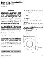
X-axis
l1
l2
= 260 mm
75 mm
D
b3 = 130 mm
W
b1
Tf
l3
Tw l3
b2
175 mm
Z-axis AXIS SYSTEM USED
B = 325 mm
b2
b3 = 130 mm
l2
75 mm L=
100 mm
410 mm
Pedestal Base Plate
A) INPUT DATA a) Staad Input Reactions CASE
Fx (kN)
Fy (kN)
1
Max Fx
2011
L/C
20.213
9.377
Fz (kN) Mz (kNm) -2.188
-7.366
2
Max Fy
2013
20.161
13.382
2.692
-7.321
3
Max Fz
2021
18.587
11.873
3.404
-6.719
4
Max Mz
2010
-20.575
9.777
-2.126
7.547
5
Min Fx
2010
-20.575
9.777
-2.126
7.547
6
Min Fy
2041
3.884
-3.287
0.002
-2.489
7
Min Fz
2016
-18.906
6.883
-2.968
6.893
8
Min Mz
2011
20.213
9.377
-2.188
-7.366
Fx (kN)
Fy (kN)
Fz (kN)
Mz (kNm)
20.21
13.38
3.40
-7.32
Design Loads :
b) Material Concrete Cube Compressive Strength of Concrete, fcu
=
25
N/mm2
Unit weight of Concrete γc Young's Modulus of Concrete Ec
=
25
kN/m3
Yield Strength of Steel fy Unit weight of Steel γst
=
275
N/mm2
=
78.5
kN/m3
2 = 25000.00 N/mm
Steel
Young's Modulus of Steel Es Partial Safety Factor for Material (yielding) γm0
= =
200000 N/mm2 1.15
Document No. :
Rev. :
Project No.
Sheet :
: 1275078 Document Title : Base Plate Design
B
c) Column Details Size
D (mm)
W (mm)
Tf (mm)
Tw (mm)
Tp (mm)
Wp (mm)
UPN160
160
65
10.5
7.5
0
0
(4W + 2D - 2Tw ) = C/S area of column Acol =
565
mm
2407.5
mm2
d) Anchor Bolt Data Grade of Bolt Bolt size to be used, db
=
8.8
=
M20
(As per 24-84-75-9901 Design basis for civil and structure)
20
Bolt dia, Effective Tensile Stress Area At = Effective Shear Stress Area As = Shank area Asb =
168
mm2
(As per ES 30-99-75-3232)
227
mm2
(As per ES 30-99-75-3232)
mm2
=
168 120
N/mm2
Shear stress of anchor bolt, Ps =
(As per ES 30-99-75-3232)
80
N/mm2
(As per ES 30-99-75-3232)
Tensile stress of anchor bolt, Pt Size of bolt hole
=
25
mm
Allowable tension, Ta Allowable shear, Va
=
24
kN
= Total No of bolts, Nb = = No. of bolts on Z axis Nbt
49 4
kN
( Note : Enter tension and shear capacities of bolt if available otherwise leave cells blank )
= Prov. distance from outer face of column flange to anchor bolts C/C distance between bolts (parellel to web) l1 = C/C distance between bolts (parellel to flange) b1 =
50
mm
OK
260
mm
OK
175
mm
OK
=
75
mm
OK
( Table 29 of BS 5950-1 )
Edge distance to Anchor bolts (parellel to flange) b2 =
75
mm
OK
(Min 1.25 x Bolt hole dia)
Edge distance to Anchor bolts (parellel to web) l2
(As per ES 30-99-75-3232)
0 4
e) Base Plate Data l3
=
100
mm
b = Projection of base plate beyond column flange (parellel 3 to flange) Length of base plate L =
130
mm
410
mm
Projection of base plate beyond column flange (parellel to web)
Width of base plate B = Area of base plate A1 =
325 mm 133250 mm2
f) Pedestal Data Length of pedestal L' = Width of pedestal B' = Area of pedestal A2 =
460
mm
375 mm 172500 mm2
g) Permissible Stress Values Max permissible bearing stress of concrete, Fp
= 0.45 x fck x sqrt(A2/A1) =
Ultimate bending stress of steel, σbs
12.81 = fy/γm0 239.14 =
N/mm2 N/mm2
Ultimate shear stress of steel = fy / [sqrt(3) x γm0 ] = 138.07 N/mm2
For Wrench tightening (Min 1.7 x Bolt hole dia) (Min 4 x dia of bolt)
Document No. :
Rev. :
Project No.
Sheet :
: 1275078 Document Title : Base Plate Design
B
Document No. :
Rev. :
Project No.
Sheet :
: 1275078 Document Title : Base Plate Design
B
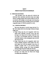
B) CALCULATION OF BEARING LENGTH e = M/P = 547.08 Pmax. =
-13.382 kN (down)
Column UPN160
tp
fp(max) Xc
T=Tb x (Nbt/2) L
P M Eccentricity, e c/s area of bolts in tension, As Modular Ratio, m
= -13.4 = -7.32
kN ---------------
Compression
kN-m
= 547.08
mm = 628.31853 mm2 = 8.000
= ABS (M / P) = (Nbt / 2) x π x db2 / 4 = Es/Ec
Refer Page no. 3.3-10 Eq. 12,13 Section 3.3 Design of Welded structures by Omar Blodgett
Xc3 + K1 Xc2 + K2 Xc + K3 = 0 Where, K1 K2 K3
= 1026.2345 = 3 (e - L/2) = 6 x m x As x [( L/2 - l2 ) + e] / B = 62831.373 = -21048510 = -K2 x [ L/2 + ( L/2 -l2)]
Solving cubic equation for Xc => Xc
= 111
mm
Is ABS(e) = M/P > N/2-Xc/3 Is N/6 < ABS(e) = Vb, O.K. Tb/Ta + Vb/Va =
Combined shear and tension check :
-0.192 + 0.0055 = -0.187
1.000 t1
x
0.41
= 10.40
x
2
2 / t1
250^2
mm
Type II : Ratio of free length to fixed length = f / g =
175 / 250
From Roarks formulae for Stress & strain on Table 26 for Rectangle plate : Three edges fixed & one edge free
= 0.70
b1 =
0.155
b3 =
0.254
a/b b1
0.081 0.173
b3
0.126 0.286
= -MAX(b1, b3) x fp(avg) x g2 / t2
0.50
Max stress, σ where, t = thickness of base plate Ignoring negative sign as tension stresses will be at same face of plate ( i.e. top or bottom for b1 & b3 case) Permissible max stress, σbs = 239.1 N/mm2 250^2
/ t22
Maximum bearing pressure =
0.900
N/mm2
Projection of base plate beyond gusset plate =
113.0
mm
325
mm
Hence,
239.1 =>
=
0.254 t2
x
0.41 = 5.24
x mm
d) Design of Stiffner Plate
Width of base plate = Ultimate bending stress of stiffner plate =
--------- Not Applicable
239.14
N/mm2
0.75
Ultimate shear stress of steel =
N/mm2
Thk.of stiffner Plate =
138.07 12
Permissible Stress in weld =
144.22
N/mm2
mm
d-i) Stiffener Plate Height Due to Bearing Pressure :Assuming maximum pressure is acting uniformly on entire base plate and 2/3 of it is shared by stiffner plate. Bending moment at the face of flange, M' =
2 x 0.9 3
M' =
2
622488.8
4 x M' sbs x t
Height of Plate required ' H1 ' =
325
x
x
113.0
113.0
x
2
N.mm 4 x 622488.75
=
=
239.14 x 12
29
mm
Height of Gusset plate ' H1 ' =
d-ii) Stiffner Plate height Due to Shear :No.of Weld face available
=
2
Size of the Weld
=
6
Shear Force at the face of flange, F' =
2 x 0.9 3
F' = Length of weld required
=
mm 325
x
2
x
11.02 kN 11.02 x 1000
113.0
=
0.7 x 6 x 144.22 x 2
9
mm
Height of Gusset plate ' H2 ' = Therefore , Height of Stiffner Plate Required = Max ( H1 , H2 )
Check for shear stress in stiffners : Maximum shear force in stiffner, F' = 11.02 kN = SF in stiffner / (thickness x height of stiffner) Shear stress in stiffner = N/mm2
d) Design of Gusset Plate
--------- Not Applicable
Maximum bearing pressure =
0.900
N/mm2
Projection of base plate beyond stiffner =
156.5
mm
Width of base plate =
410.0
mm
Ultimate bending stress of gusset plate =
239.14
N/mm2
Ultimate shear stress of steel =
138.07 108
N/mm2
Permissible Stress in weld =
N/mm2
12
Thk.of Gusset Plate =
mm
e-i) Gusset Plate Height Due to Bearing Pressure :Assuming maximum pressure is acting uniformly on entire base plate and 1/2 of it is shared by gusset plates. Bending moment at the face of flange, M' =
0.900 2
M' =
Height of Plate required ' H1 ' =
Height of Gusset plate ' H3 ' =
4 x M' sbs x t
x
410.0 2
1129705.0
=
x
156.5
x
156.5 2
N.mm 4 x 1129705.03 239.14 x 12
=
40
mm
e-ii) Gusset Plate height Due to Shear :No.of Weld face available
=
1
Size of the Weld
=
8
Shear Force at the face of flange, F' =
0.900 2
F' = Length of weld required
=
x
mm 410.0 2
x
14.44 kN 14.44 x 1000 0.7 x 8 x 108 x 1
156.5
=
24
Height of Gusset plate ' H4 ' = Therefore , Height of Gusset Plate Required = Max ( H3 , H4, Stiffner height )
Check for shear stress in gusset : Shear force in gusset, F' = Shear stress in Gusset
14.44
kN
= SF in gusset / (thickness x height of gusset) =
mm
Document No. :
Rev. :
Project No.
Sheet :
: 1275078
A
Document Title : Base Plate Design This sheet is not applicable Design of base plate subjected to partial compression (Axial compression load with moment - Both side bolts are in compression zone)
a) Check for Bearing Pressure For L/6 < ABS(e) = fp(max), O.K.
b) Tension and Shear in Anchor Bolt No. of Bolts in Tension, Maximum Tension,
= 2
No.s
= 6.43
kN
Allowable tension / bolt, Ta = 30.00 Actual tension / bolt, Tb = 3.22 Tension check :
Shear check :
kN
(As per ES 30-99-75-3232)
kN
Ta >= Tb, O.K. Shear along X-axis, Fx = 2.32 Shear along Z-axis, Fz = 0.524
kN
Allowable shear / bolt, Va = 61.25 Actual shear / bolt, Vb = 0.59
kN
kN kN
(As per ES 30-99-75-3232) = SQRT(Fx2 + Fz2 ) / Nb
Va >= Vb, O.K. Tb/Ta + Vb/Va =
Combined shear and tension check :
0.1072 + 0.0097 = 0.1169
1.000 t1
x
-0.09 = Err:502
x
250^2
2 / t1
mm
Type II : Ratio of free length to fixed length = f / g =
175 / 250
From Roarks formulae for Stress & strain on Table 26 for Rectangle plate : Three edges fixed & one edge free = -MAX(b1, b3) x fp(avg) x g2 / t2
= 0.70
b1 =
0.155
a/b
0.50
b3 =
0.254
b1
0.081 0.173
b3
0.126 0.286
Max stress, σ where, t = thickness of base plate Ignoring negative sign as tension stresses will be at same face of plate ( i.e. top or bottom for b1 & b3 case) Permissible max stress, σbs = 239.1 N/mm2 Hence,
239.1 =>
=
0.254 t2
x
-0.09 = Err:502
x mm
250^2
/ t22
0.75
d) Design of Stiffner Plate
--------- Not Applicable
Maximum bearing pressure =
-0.080
N/mm2
Projection of base plate beyond gusset plate =
105.0
mm
325
mm
Width of base plate = Ultimate bending stress of stiffner plate = Ultimate shear stress of steel = Thk.of stiffner Plate = Permissible Stress in weld =
239.14
N/mm2
138.07 20
N/mm2
108
N/mm2
mm
d-i) Stiffener Plate Height Due to Bearing Pressure :Assuming maximum pressure is acting uniformly on entire base plate and 2/3 of it is shared by stiffner plate.
Bending moment at the face of flange, M' =
2 x -0.08 3
M' =
x
2
-47775.0
4 x M' sbs x t
Height of Plate required ' H1 ' =
325
x
105.0
105.0
x
2
N.mm 4 x -47775
=
=
239.14 x 20
Err:502
mm
Height of Gusset plate ' H1 ' =
d-ii) Stiffner Plate height Due to Shear :No.of Weld face available
=
2
Size of the Weld
=
8
Shear Force at the face of flange, F' =
2 x -0.08 3
F' = Length of weld required
mm 325
x
2
x
-0.91 kN -0.91 x 1000
=
105.0
=
0.7 x 8 x 108 x 2
-1
mm
Height of Gusset plate ' H2 ' = Therefore , Height of Gusset Plate Required = Max ( H1 , H2 )
Check for shear stress in stiffners : Maximum shear force in stiffner, F' = -0.91 kN = Shear stress in stiffner SF in stiffner / (thickness x height of stiffner) = N/mm2
e) Design of Gusset Plate
--------- Not Applicable
Maximum bearing pressure =
-0.080
N/mm2
Projection of base plate beyond stiffner =
152.5
mm
Width of base plate = Ultimate bending stress of gusset plate =
410.0
mm
239.14
N/mm2
Ultimate shear stress of steel =
138.07
N/mm2
Permissible Stress in weld =
108
N/mm2
Thk.of Gusset Plate =
20
mm
e-i) Gusset Plate Height Due to Bearing Pressure :Assuming maximum pressure is acting uniformly on entire base plate and 1/2 of it is shared by gusset plates. Bending moment at the face of flange, M' = -0.080 2 M' =
Height of Plate required ' H1 ' =
x
410.0 2
-95350.6
4 x M' sbs x t
x
152.5
4 x -95350.63 239.14 x 20
Height of Gusset plate ' H3 ' =
e-ii) Gusset Plate height Due to Shear :=
1
Size of the Weld
=
8
Shear Force at the face of flange, F' = -0.080 2
x
152.5 2
N.mm
=
No.of Weld face available
x
mm 410.0 2
x
152.5
=
Err:502
mm
F' = Length of weld required
=
-1.25 kN -1.25 x 1000 0.7 x 8 x 108 x 1
=
-2
Height of Gusset plate ' H4 ' = Therefore , Height of Gusset Plate Required = Max ( H1 , H2, Stiffner height )
Check for shear stress in gusset : Shear force in gusset, F' = -1.25 kN = SF in gusset / (thickness x height of gusset) Shear stress in Gusset =
mm
Document No. : Project No. : 1275078 Document Title : Base Plate Design
Rev. : Sheet :
B
Design of base plate subjected to partial compression (Axial compression load with moment - Bolts on one side are in tension)
a) Check for Bearing Pressure For ABS(e) > (L/2 - Xc/3), base plate is in partial copmression and bolts on one side are in tension zone. Hence, bearing length, Xc = 111.19 Maximum bearing pressure : T = -P x (L/2 - Xc/3 - e) / [L/2 - Xc/3 + (N/2 - l2)] = 17.029 fp(max) = 2 x (ABS(P)+T) / (Xc x B) = 1.683 fp(min) = pressure at distance Xc = 0.000 Max permissible bearing stress of concrete, Fp = 12.81 Check :
mm kN N/mm2 N/mm2 N/mm2
Fp >= fp(max), O.K.
b) Tension and Shear in Anchor Bolt Tensile capacity of anchor bolt =
0.8 x Pt x An (Ref Cl.6.3.4.2 of BS5950-1 )
=
Min [(0.8 x120 x 168) / (1000)
=
Min (16.13)
=
16.13
Shear capacity of anchor bolt =
kN
Ps x As (Ref Cl.6.3.2 of BS5950-1 )
=
[80x227]
=
27.24
kN
Allowable tension / bolt, Ta = 24.00 Tb = T/(Nb / 2) = 8.51 Actual tension / bolt,
kN
Tension check :
kN
Ta >= Tb, O.K. Allowable shear / bolt, Va = 49.00 Actual shear / bolt, Vb = 5.12
Shear check :
kN kN
= SORT(Fx2 + Fz2 ) / Nb
Va >= Vb, O.K. Tb/Ta + Vb/Va =
Combined shear and tension check :
0.3548 + 0.1046 = 0.4594
1.000 t1
x
-0.21 = Err:502
x
250^2
2 / t1
mm
Type II : Ratio of free length to fixed length = f / g =
175 / 250
From Roarks formulae for Stress & strain on Table 26 for Rectangle plate : Three edges fixed & one edge free
b1 = b3 =
= 0.70 0.155 0.254
a/b b1
0.50
0.75
0.081
0.173
b3
0.126
0.286
= -MAX(b1, b3) x fp(avg) x g2 / t2 Max stress, σ where, t = thickness of base plate Ignoring negative sign as tension stresses will be at same face of plate ( i.e. top or bottom for b1 & b3 case) Permissible max stress, σbs = 239.1 N/mm2 Hence,
239.1 =>
=
0.254 t2
x
-0.21 = Err:502
x mm
250^2
/ t22
2) For Tension : a
c
a
c
d
Tb3 f/2
Tb2
Tb4 b
f/2
Tb1
Tb3
Type I
Type II
Maximum Tension in Bolt, Tb = Permissible max stress, σbs =
9 239.14
kN N/mm2
Type I : a
=
50
mm
c
=
75
mm
b
=
88
mm
d
=
75
mm
Considering both projections cantilever Let Total load Tb is transferred as Tb1 and Tb2 on the edges as shown thus,
Tb = Tb1 + Tb2 ----------- (Eq. 1)
Let d1 and d2 be the deflections due to Tb1 and Tb2,
Hence,
From Eq. 2 Tb1 x b3/3EI = Tb2 x a3/3EI
From Eq. 1 Tb = Tb1 + Tb2
Tb1 = Tb2 x (a/b)3 Tb1 = (50/87.5)^3 x Tb2 x Tb2 = 0.187
9 Tb2
= =
Tb1
=
Moment at edge 1, M1 = Tb1 x b = Moment at edge 2, M2 = Tb2 x a =
0.187 x Tb2 + Tb2
358789 N-mm 4 x M1 sbs x B1 4 x M2
Thickness of Plate required ' t4 ' =
sbs x B2
7.2
kN
1.3
kN resisting width, B1 = resisting width, B2 =
117156 N-mm
Thickness of Plate required ' t3 ' =
d1 = d2 ----------------- (Eq. 2)
= =
6 x 117156 239.14 x 125 6 x 358789 239.14 x 162.5
125
mm
163
mm
=
mm
=
mm
Type II : a
=
50
f
=
175 mm
mm
c
=
75
mm
Considering both projections cantilever Let Total load Tb is transferred as Tb3 and Tb4 on the edges as shown thus, Let d3 and d4 be the deflections due to 2xTb3 and Tb4, From Eq. 4 Tb4 x a3/3EI = 2Tb3 x f3/48EI Tb3 = 8 x Tb4 x (a/f)3 Tb3 = 0.187 x Tb4
Thickness of Plate required ' t5 ' = Thickness of Plate required ' t6 ' =
d1 = d2 ----------------- (Eq. 4)
From Eq. 3 Tb = 2 x Tb3 + Tb4 9 = 2 x 0.187 x Tb4 + Tb4 Tb4 = 6.2 kN Tb3 = 1.2 kN
= 8 x Tb4 x (50/175)^3
Moment at edge 3, M3 = Tb3 x f/2 = Moment at edge 4, M4 = Tb4 x a =
Tb = 2 x Tb3 + Tb4 -------- (Eq. 3) Hence,
resisting width, B3 = resisting width, B4 =
101399 N-mm 309851 N-mm 4 x M3 sbs x B3 4 x M4 sbs x B4
= =
4 x 101399 239.14 x 125 4 x 309851 239.14 x 175
125
mm
175
mm
=
mm
=
mm
d) Design of Stiffner Plate
--------- Not Applicable
Maximum bearing pressure =
1.680
N/mm2
Projection of base plate beyond gusset plate =
113.0
mm
325
mm
Width of base plate = Ultimate bending stress of stiffner plate = Ultimate shear stress of steel = Thk.of stiffner Plate =
239.14
N/mm2
138.07 12
N/mm2
108
N/mm2
Permissible Stress in weld =
mm
d-i) Stiffener Plate Height Due to moment :Assuming maximum pressure is acting uniformly on entire base plate and 2/3 of it is shared by stiffner plate.
Bending moment at the face of flange due to bearing pressure ,
Mc' =
2 x 1.68
x
3 Mc' =
325 2
1161979.0
x
113.0
Maximum moment on stiffner, M' = MAX (Mc' , Mt') 4 x M' sbs x t
113.0 2
N.mm
Total tension carried stiffner = Tb1 + Tb3 = 1.3 + 1.2 = 2.5 Mt' = 2.49775837879043 x 1000 x 113 Bending moment at the face of flange due to tension in bolt , Mt ' = 282246.7 N.mm
Height of Plate required ' H1 ' =
x
=
kN
1161979.0
4 x 1161979
=
N.mm
=
239.14 x 12
40
Height of Gusset plate ' H1 ' =
d-ii) Stiffner Plate height Due to Shear :No.of Weld face available
=
2
Size of the Weld
=
8
Shear Force at the face of flange due to bearing pressure,
Fc' =
Fc' = Ft' = Shear Force at the face of flange due to tension in bolt,
2 x 1.68 3
b mm
x
20.57
kN
2.5
kN
325 2
Maximum shear in stiffner, F' = MAX (Fc' , Ft') = 20.57 x 1000 Length of weld required = 0.7 x 8 x 108 x 2
x
113.0
20.6 =
kN 17
Height of Gusset plate ' H2 ' = Therefore , Height of Gusset Plate Required = Max ( H1 , H2 )
Check for shear stress in stiffners : Maximum shear force in stiffner, F' = Shear stress in stiffner
20.57 kN = SF in stiffner / (thickness x height of stiffner) = N/mm2
mm
mm
e) Design of Gusset Plate
--------- Not Applicable
Maximum bearing pressure =
1.680
N/mm2
Projection of base plate beyond stiffner =
156.5
mm
Width of base plate = Ultimate bending stress of gusset plate =
410.0
mm
239.14
N/mm2
138.07 108
N/mm2
Ultimate shear stress of steel = Permissible Stress in weld =
N/mm2
12
Thk.of Gusset Plate =
mm
e-i) Gusset Plate Height Due to Bearing Pressure :Assuming maximum pressure is acting uniformly on entire base plate and 1/2 of it is shared by gusset plates. Bending moment at the face of flange, M' =
1.680
x
2 M' =
x
2
2108782.7
4 x M' sbs x t
Height of Plate required ' H1 ' =
410.0
156.5
156.5
x
2
N.mm 4 x 2108782.73
=
239.14 x 12
=
Height of Gusset plate ' H1 ' =
e-ii) Gusset Plate height Due to Shear :No.of Weld face available
=
1
Size of the Weld
=
6
Shear Force at the face of flange, F' =
1.680 2
F' = Length of weld required
=
mm
x
410.0 2
x
26.95 kN 26.95 x 1000 0.7 x 6 x 108 x 1
156.5
=
59
Height of Gusset plate ' H2 ' = Therefore , Height of Gusset Plate Required = Max ( H1 , H2, Stiffener height )
Check for shear stress in gusset : Shear force in gusset, F' = 26.95 kN = SF in gusset / (thickness x height of gusset) Shear stress in Gusset =
mm
54
mm
DESIGN OF BASE PLATE MKD BP1 1 2 A) Input Data: 3 a) Column Data: 4 Select Size of Column : UC203X203X86 5 YES 250 Whether Flange Plates Provided Size of Flange Plate : Width = 6 20 Built Up Column Properties: Thickness = 7 Column Properties: 109.6 209.6 A = cm.^2 A = cm.^2 ={109.6+25x2x2} 8 222.2 262.2 d= mm d= mm ={222.2+20x2} 9 12.7 12.7 10 tw = mm tw = mm 11 209.1 229.6 bf = mm bf = mm ={(209.1+250)/2} X 12 20.50 40.5 tf = mm tf = mm ={20.5+20} 13 14 ED1=60 ED3=400 15 b) Anchor Bolt Data: 6 Total No. of Bolts, Nb = 16 0 Bolts on X-axis = ED2=60 17 be 18 6 = Nbt 19 39 Bolt Diameter, db = mm 20 ED4=480 60 Bolt Edge Dist., ED1 = mm B=600 21 60 Bolt Edge Dist., ED2 = mm 22 400 Bolt Edge Dist., ED3 = mm 23 480 Bolt Edge Dist., ED4 = mm 24 25 26 m=128.9 27 c) Base Plate Data: d=262.2 28 520 Base Plate Length, N = mm 29 600 Base Plate Width, B = mm N=520 30 250 (As per Design Basis) Plate Yield Stress, fy = Mpa 31 Perm. bend. stress, sbs = 187.5 (0.75x Fy) Plan Mpa 32 33 Elasticity of Steel, Es = 2.0E+05 Mpa 34 35 d) Pedestal Data: 36 25 (As per Design Basis) Grade of Conc., fck = Mpa 37 750 Pedestal Length, Np = mm 38 800 Pedestal Width, Bp = mm 39 40 41 Conc. Bearing Area, A1 = 6000.0 cm.^2 ={75x80} 42 Base Plate Area, A2 = 3120.0 cm.^2 ={52x60} 43 0.25*25*Min(2,SQRT(6000/3120)) Permissible Bearing Stress, = 44 Fp 8.67 (Clause 34.4, IS : 456-2000) = Mpa 45 2.5E+04 (Clause 6.2.3.1, IS : 456-2000) Elasticity of conc., Ec = Mpa 46 47 48 49 50
JOB NO.
Aker Kvaerner Powergas PLL CLIENT PROJECT OHCU-HALDIA REFINERY SUBJECT CALCULATIONS FOR BASE PLATE C940001 R3
mm mm
n=185.23
bf=229. Z n=185.23 m=128.9
CALCULATION NUMBER
2090/1473
EQPT NO.
10144-PEIN04-91-6102-XXX
REV
PREPD BY
DATE
CHKD.BY
3 2 1 0
AHT
29/03/2008
VDB
DATE
29/03/2008
REACTOR STRUCTURE FOR 91-R-01, 02 & 03
SH
1
OF
C940001 R3 1 2 3 4 5 6 7 8 9 10 11 12 13 14 15 16 17 18 19 20 21 22 23 24 25 26 27 28 29 30 31 32 33 34 35 36
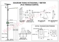
1 2 B) Base Plate Analysis: Y-axis 3 a) Load Data: 4 SR. No. = LC No. 1 = 221 X-axis 5 Pmax. -411.11 kN Node No. 104 = = M 6 Z-axis 7 FX -0.89 kN = (Note :- Forces as per Right 8 hand thumb rule) 9 = 10 FZ -20.43 kN = X-Axis : Across column Web 11 Z-Axis : Along column Web 12 Mx 50.00 kN.m = Y-Axis : Vertical 13 FX :-Force along X-Axis 14 My -0.02 kN.m = FY :-Force along Y-Axis 15 FZ :-Force along Z-Axis 16 17 Mz 0.00 kN.m = MX :-Moment about X-axis 18 MZ :-Moment about Z-axis 19 b) Eccentricity, Bearing Length, and Bearing Pressures: V(total)=SQRT(FX2+FZ2) 20 21 e = M/P = 121.62 22 23 24 Pmax. = -411.1 (down) 25 26 27 28 UC203X203X86 Col. with 250X20 Flange Plates 29 30 31 32 tp 33 34 fp(max) = 35 3.237 Xc=430.06 36 T=Tb*(Nbt/2) 37 N=520 38 39 40 Elevation 41 42 Compression P= M= -411.1 kN 50.00 kN-m 43 121.62 mm Eccentricity, e = =ABS(M/P) 44 8.00 As = (Nbt/2)*pi*db^2/4 = 3583.77 Modular Ratio (MR) = Es/Ec = 45 46 47 Refer Page no. 3.3-10 Eq. 12,13 Section 3.3 Design of Welded structures by Omar Blodgett 48 49 Xc^3 +K1*Xc^2 + K2*Xc + K3 = 0 50 Where,
K1 = 3*(e-N/2)
=
-415.1
K2 = 6*MR*As*((N/2-ED1)+e) / B
= =
-42416560.4
K3 = -K2*(N/2+(N/2-ED1))
92209.9
Xc^3 + 3*(e-N/2) * Xc^2 + 6*MR*As/B*((N/2-ED1)+e) * Xc - 6*MR*As/B*((N/2-ED1)+e)*(N/2+(N/2-ED1)) = 0 Solve cubic equation for Xc
=>
Xc =
JOB NO.
Aker Kvaerner Powergas PLL CLIENT PROJECT OHCU-HALDIA REFINERY SUBJECT CALCULATIONS FOR BASE PLATE C940001 R3
430.06
mm
CALCULATION NUMBER
2090/1473
EQPT NO.
10144-PEIN04-91-6102-XXX
REV
PREPD BY
DATE
CHKD.BY
3 2 1 0
AHT
29/03/2008
VDB
DATE
29/03/2008
REACTOR STRUCTURE FOR 91-R-01, 02 & 03
SH
2
OF
C940001 R3 1 2 3 4 5 6 7 8 9 10 11 12 13 14 15 16 17 18 19 20 21 22 23 24 25 26 27 28 29 30 31 32 33 34 35 36
1 2 3 For case of axial compression load plus moment: 4 116.65 YES then Xc = Is ABS(e) = M/P > N/2-Xc/3 i.e. 121.62 > 430.1 mm 5 NO Is N/6 < ABS(e) YES 1 2 2 N/mm Maximum bearing pressure, fpmax = Bearing pressure at distance g , fp1 = 3 N/mm2 430.1 4 128.9 5 Moment at the face of column = N-mm 6 7 fpmax 6xM 8 Thickness of Base plate, tp = = mm fp sbs * B 1 9 10 11 b) For Tension :12 kN Maximum Tension in Bolt, Tb = 13 be = MIN{ 2(m-ED1) or (m-ED1)+ED4/(2*(nbt-1)) or ED4/(nbt-1) or ED2+(m-ED1) or ED2+ED4/(2*(nbt-1)) } 14 = mm 15 Moment at the face of column N-mm = Tb * (m-ED1) = 16 6xM 17 = = mm Thickness of Base plate, tp sbs * B 18 19 20 21 22 2) Thickness calculation for stiffened Base Plate :23 a) For Compression :24 2 No. of Stiffner Plates perpendicular to Column Flange = 25 300 ### k = 150.0 mm Stiffner distance, f = mm 26 27 20 g = 128.9 mm Stiffner Thickness = mm 28 g 29 30 Type I 31 k 32 33 34 35 Type II 36 f 37 38 39 40 41 42 43 44 g Corresponding Neutral axis depth = 45 g 430.1 46 g f/2 47 k 48 49 f/2 fpmax 50 fp1
Type I Type I :
Type II Maximum bearing pressure, fpmax = Bearing pressure at distance g , fp1 = Average Bearing Pressure = fpavg = Ratio = 128.9/150 = 0.86
3.24 N/mm2 2.27 N/mm2 2.75 N/mm2 (Ratio of min side to max.side )
JOB NO.
Aker Kvaerner Powergas
2090/1473 REV
CLIENT
PLL
CALCULATION NUMBER
3 2
PREPD BY
EQPT NO.
10144-PEIN04-91-6102-XXX DATE
CHKD.BY
DATE
REACTOR STRUCTURE FOR 91-R-01, 02 & 03
PROJECT OHCU-HALDIA REFINERY SUBJECT CALCULATIONS FOR BASE PLATE C940001 R3 1 2 3 4 5 6 7 8 9 10 11 12 13 14 15 16 17 18 19 20 21 22 23 24 25 26 27 28 29 30 31 32 33 34
2 1 0
REACTOR STRUCTURE FOR 91-R-01, 02 & 03 AHT
29/03/2008
VDB
29/03/2008
SH
5
OF
1 2 a/b 0.75 From Roarks formulae for Stress & strain on Table 26 for Rectangle plate : ie 3 b1 1.246 Two adjacent edges fixed, two remaining edges free between 4 b1 = 1.475 5 Max stress, s = - b1 x fpavg x g2 / t2 where, t = thickness of base plate 6 (Ignoring negative sign as tension stresses will be at same face of plate ( ie top or bottom for b1 ) 7 Permissible max stress = sbs = 187.5 N/mm2 8 9 10 Hence, 187.5 = 1.475 x 2.75 x 16615 / t2 11 t = 18.96 mm => 1 12 13 14 Type II : 15 2.33 (Ratio of free length to fixed length ) 16 Ratio = f / g = 17 a/b 2.00 From Roarks formulae for Stress & strain on Table 26 for Rectangle plate : ie 18 b1 1.226 Three edges fixed & one edge free between 19 b = b = b3 1.568 1.514 1.704 1 3 20 21 2 2 where, t = thickness of base plate 22 Max stress, s = - max(b1, b3,) x fpavg x g / t (Ignoring negative sign as tension stresses will be at same face of plate ( ie top or bottom for b1 & b3 case) 23 24 Permissible max stress = sbs = 187.5 N/mm2 25 26 Hence, 187.5 = 1.704 x 2.75 x 16615 / t2 27 t2 = 20.38 mm => 28 29 b) For Tension :30 a c a c p3 31 32 33 d f/2 34 35 p2 p4 36 b f/2 37 38 p3 39 p1 40 Type I Type II 41 Type I : 2 kN Maximum Tension in Bolt, Tb = 42 60 mm a = 68.9 mm c = 43 60 mm b = 90 mm d = 44 45 46 47 48 49 50
1.0 1.769
3.00 2.105 1.982
Considering both projections cantilever Let Total load p is transferred as p1 and p2 on the edges as shown thus, p = p1 + p2 ------- (Eq 3) Let d1 and d2 be the deflections due to p1 and p2 --> d1 = d2 --------------------------------------- (Eq. 4)
From Eq. 4 p1*b3/3EI = p2*a3/3EI p1 = p2*(a/b)3
From Eq. 3 p = p1 + p 2 => 2 = 0.449 x p2 + p2 p2 = 1.5 kN p1 = 0.7 kN
p1 = (68.9/90)^3 x p2
=
0.449 x p2
Moment, M1 = p1*b = Moment, M2 =p2*a =
60026 102420
N-mm N-mm
resisting width, B1 = resisting width, B2 =
JOB NO.
Aker Kvaerner Powergas PLL CLIENT PROJECT OHCU-HALDIA REFINERY SUBJECT CALCULATIONS FOR BASE PLATE C940001 R3
129 150
mm mm
CALCULATION NUMBER
2090/1473
EQPT NO.
10144-PEIN04-91-6102-XXX
REV
PREPD BY
DATE
CHKD.BY
3 2 1 0
AHT
29/03/2008
VDB
DATE
29/03/2008
REACTOR STRUCTURE FOR 91-R-01, 02 & 03
SH
6
OF
C940001 R3 1 2 3 6*M1 6 * 60026 Thickness of Plate required ' t3 ' = = = mm 3.9 4 sbs*B1 187.5 * 128.9 5 6*M2 6 * 102420 Thickness of Plate required ' t4 ' = = = mm 6 4.7 sbs*B2 187.5 * 150 7 8 9 Type II : 10 11 a = 68.9 mm c = 60 mm 12 f = 300 mm 13 Considering both projections cantilever 14 Let Total load p is transferred as p3 and p4 on the edges as shown thus, p = 2 * p3 + p4 ------- (Eq. 5) 15 Let d1 and d2 be the deflections due to (2 * p3) and p4 -> d1 = d2 ---------------------------------------(Eq. 6) 16 From Eq. 5 From Eq. 6 17 3 3 p p4*a /3EI = (2p3)(f) /48EI = 2p3 + p4 18 19 p3 = 8*p4*(a/f)3 = 8 * p4*(68.9/300)^3 2 = 2 x 0.097 x p4 + p4 20 p4 = 1.8 kN p3 = 0.097 x p4 21 p3 = 0.2 kN 22 Moment, M1 =p4*a = 124265 N-mm resisting width, B1 = 300 mm 23 Moment, M2 =p3*f /2= 26242 N-mm resisting width, B2 = 129 mm 24 6*M1 6 * 124265 25 Thickness of Plate required ' t5 ' = = = mm 3.6 sbs*B1 187.5 * 300 26 27 6*M2 6 * 26242 Thickness of Plate required ' t6 ' = = = mm 2.6 28 sbs*B2 187.5 * 128.9 29 30 31 32 Provide BASE PLATE of 21 mm thickness with stiffners 33 34 35 36 37 38 39 40 41 42 43 44 45 46 47 48 49 50
JOB NO.
Aker Kvaerner Powergas
2090/1473 REV
PLL CLIENT PROJECT OHCU-HALDIA REFINERY SUBJECT CALCULATIONS FOR
CALCULATION NUMBER
3 2 1 0
PREPD BY
EQPT NO.
10144-PEIN04-91-6102-XXX DATE
CHKD.BY
DATE
REACTOR STRUCTURE FOR 91-R-01, 02 & 03
BASE PLATE C940001 R3 1 2 3 4 5 6 7 8 9 10 11 12 13 14 15 16 17 18 19 20 21 22 23 24 25 26 27 28 29 30 31 32 33 34 35
0
AHT
29/03/2008
VDB
29/03/2008
SH
7
OF
1 2 D) Design of Gusset & Stiffner Plate :3 4 D.1) Gusset Plate Height Due to Bearing Pressure :5 6 Maximum bearing pressure = 3.240 N/mm2 7 Projection of base plate beyond stiffner = 140.0 mm 8 Width of base plate = 520.0 mm 9 10 Thk.of Gusset Plate = 20 mm 11 Fy for Plate = 250 N/mm2 12 13 Assuming maximum pressure is acting uniformly on entire base plate and 1/2 of it is shared by gusset plates. 14 15 Bending moment at the face of flange (M') = 3.24 x 520 x 140 x 140 16 2 2 2 17 M' = 4127760.0 N.mm 18 19 20 Permissible Stress in Plate = 0.6 Fy = 150 Mpa 21 22 6*M' 6 * 4127760 23 Height of Plate required ' H1 ' = = = 91 mm sbs * t 150 * 20 24 25 Height of Gusset plate ' H1 ' = 100 mm 26 27 28 D.2) Gusset Plate height Due to Shear :29 30 D.2.1) Maximum bearing pressure = 3.240 N/mm2 31 Projection of base plate beyond stiffner = 140.0 mm 32 Width of base plate = 520.0 mm 33 No.of Weld face available = 2 34 35 Size of the Weld = 8.0 mm 36 Permissible Stress in weld = 108.0 N/mm2 37 38 Shear Force at the face of flange (F') = (3.24 / 2) x (520 / 2) x 140 39 F' = 58.97 kN 40 41 Length of weld required = 58.97 x 1000 42 0.7 x 8 x 108 x 2 43 44 45 = 49 mm 46 Height of Gusset plate ' H2 ' = 50 mm 47 48 Therefore , Height of Gusset Plate Required = Max ( H1 , H2 ) 49 Max ( 100, 50 ) = 50 = D.2.2) SF in Gusset Shear stress in Gusset
PLL CLIENT PROJECT OHCU-HALDIA REFINERY SUBJECT CALCULATIONS FOR BASE PLATE C940001 R3
mm
= (fp / 2) x (B / 2) x (Proj.) = 58.97 kN = SF in gusset / (t x d) = 29.484 N/mm2