![Tank Anchor Bolt Design [PDF]](https://pdfs.asia/img/200x200/tank-anchor-bolt-design.jpg)
7 0 52 KB
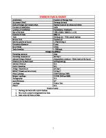
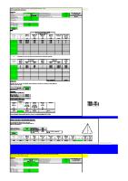
ANCHOR BOLT CALCULATION FOR REMINERALIZER VESSEL A/B WIND LOAD Equipment Details
1.1
L
=
3
m
W H cg
= = =
0 6 3.265
m m m
=
34.7222 m/s
=
0.95
(under Chimneys, Tanks…-Round)
Importance Factor given in Table 6-1 of ACSE 7-05 I
1.4
53010 8 24
Wind Directionality Factor given in Table 6-4 of ASCE 7-05 Kd
1.3
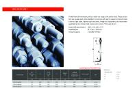
No. of Anchor Bolt (n) = Dia. of Anchor Bolt =
8500
Basic Wind Speed (ASCE 7-05 Sec. 6.5.4) V
1.2
Empty Weight (WE) = Operational Weight (WO) =
=
1.15
(Equipment not Containing Hydrocarbon)
Surface Roughness Category and Exposure Category - Surface roughness D shall apply to this project - Exposure Category D shall apply to this project Based on ASCE 7-05 Table 6-2 Terrain exposure constant shall be as follows: α = 11.50 Zg = 213.42 m
1.5
Wind velocity pressure exposure coefficient for Z < = 4.572 m Kz
=
2.01
(
4.572 Zg
)
=
2.01
(
4.572 213.42
)
=
1.03
2/α
2/α
for 4.572 m < Z < Zg USE THIS FORMULA Kz
=
2.01
(
Z Zg
)
=
2.01
(
6 213.42
)
=
1.08
2/α
2/α
1.08 1.6
Topographic Factor defined in Section 6.5.7 of ASCE 7-05 Kzt
=
1.00
Page 1 of 15
1.7
Gust Effect Factor defined in Section 6.5.8 of ASCE 7-05 G
=
0.90
Page 2 of 15
1.8
Velocity Pressure qz
2 = 0.613 Kz Kzt Kd V I
= 1.9
872.05 N/m²
Net Force Coefficient Cf
=
0.55
1.10 Design Wind Loads F
= (qz * G * Cf) * Af =
7795.83
N
1.11 Wind Moment M = F * cg =
25453.38 25.45
N*m KN*m
SEISMIC LOAD 2.1
2.2
Mapped Acceleration Parameters SS
=
0.188
at short period (0.2 sec)
S1
=
0.067
at 1.0 sec period
Site Class (ASCE 7-05 Table 20.3-1) D
2.3
2.4
=
Site Class
Site Coefficient (ASCE 7-05 Table 11.4-1, Table 11.4-2) Fa
=
1.60
at short period
FV
=
2.40
at 1.0 sec period
Adjusted MCE Spectral Response Acceleration Parameters for short period SMS = Fa * SS =
0.30
for 1.0 sec. period SM1 = FV * S1 = 2.5
0.16
Design Spectral Response Acceleration Parameters for short period 2 SDS = SMS 3 = 0.20 for 1 second period 2 SD1 = SM1 3 Page 3 of 15
=
2.6
Peak Ground Acceleration PGA =
2.7
0.11
0.04
Design Response Spectrum T
=
Ta
x = Ct * h n
where Ct = x =
0.0488 as defined in Table 12.8-2 of ASCE 7-05 0.75 as defined in Table 12.8-2 of ASCE 7-05
Ta
x = Ct * h n = 0.19
TL
=
T0
= =
TS
= =
4.0
0.2
sec (long-period transition period as per API 650)
SD1 SDS
0.11
sec
SD1 SDS 0.53
sec
for Sa, use T0 < = T < Ts Sa 2.8
SDS
=
0.20
Importance Factor I
2.9
=
=
1.25
(Equipment not Containing Hydrocarbon)
Seismic Design Category D
= Category
2.10 Response Modification Factor R
=
3.00
from Table 15.4-2 of ASCE 7-05
2.11 Seismic Response Coefficient CS
SDS = =
R ) I 0.08 (
2.12 Seismic Base Shear V = CS W = 43.45
kN Page 4 of 15
2.13 Redundancy Factor ρ =
1.00
Page 5 of 15
2.14 Effect of Horizontal Seismic Forces E h = ρ QE = 43.45
kN
2.15 Load per bolt due to horizontal seismic force Fh
= Eh / n = 5.43
kN
### #N/A
#N/A
kN
(allowable)
#N/A
kN
(allowable)
2.16 Effect of Vertical Seismic Forces EV = 0.2 SDS * D where D = effect of Dead Load =
20.86
kN
2.17 Load per bolt due to vertical seismic force FV
= EV / n = 2.61
kN
### #N/A
2.18 Gravity Load FG
= WO / n 65.0035 kN
FG > FV , therefore no need to calculate tensile stress 2.19 Seismic Load Effect E = Eh + EV = 64.31
kN
2.20 Seismic Moment M = V * cg =
141.87
kN*m
2.21 Force on each bolt F2 = E / no. of bolts =
Note:
8.04
kN
### #N/A
#N/A
kN
(allowable)
Both wind force & seismic force act in the horizontal direction are not additive. The maximum of the two will be considered for anchor bolt design
Page 6 of 15
DIAMETER OF ANCHOR BOLT Govern moment = M
=
141.87
kN*m
*
6000.00
T
mm
(Assuming the anchor bolts will carry the full moment) 141868288.15 N*mm
=
T
*
6000.00
T
=
23644.71
T
= As * Ft
Ft
= 0.60 * Fy = 0.60 * 345 = 207 Mpa
mm
N
where
Number of anchor bolts assumed to take the total moment= T 23644.71
= As * Ft = ∏ (d²) 4
Diamin = 8.53 Diamin