![Aad03040d Ol [PDF]](https://pdfs.asia/img/200x200/aad03040d-ol.jpg)
12 0 6 MB
Machine Translated by Google
foreword
Thank you very much for purchasing Panasonic products. ·Please read the instruction manual carefully to ensure safe and correct use of this product. · Please keep this instruction manual in a safe place.
About the application of this product • Do not use our company's elevator door controller for purposes other than elevator door control. • Please fully confirm the safety and applicability of the main elevator system before using it. To avoid major accidents, be sure to set up safety measures such as double safety mechanisms and fail-safe. • Do not use this product on loads other than three-phase AC permanent magnet synchronous motors.
i
Machine Translated by Google
Machine Translated by Google
Safety Precautions
Before installation, operation, maintenance and inspection, please be sure to read this manual and its attached documents thoroughly so as to use it correctly. Use it only after you are proficient in the conditions, safety information and precautions of the equipment. This manual is divided into two levels of "Danger" and "Caution" in the safety precautions column.
Incorrect operation can result in a dangerous situation that could result in death or serious injury.
In the event of mishandling, hazardous conditions can occur, situations that may result in moderate or minor injury, and situations where item damage may occur.
In addition, even if
The matters listed in the
lead to serious consequences.
In both cases, what is recorded is important and must be strictly observed.
2
Machine Translated by Google Safety Precautions
1. System Design
Danger •The STOP key is not used for emergency stop, so prepare an emergency stop switch separately. •Please use the door clipping after fully confirming the safety and functional operability in the elevator main system Checkout function. •Be sure to input a safety sensor to the main controller of the elevator body, and perform door jamming detection on the main controller side. The trapping detection function of the elevator door controller will not be activated in the open arrival area and the closed arrival area. Be sure to take double safety measures. •Be sure to input the arrival signal (limit switch, etc.) to the main controller of the elevator body, and perform door arrival detection on the main controller side. Do not use the elevator door controller open/close arrival signal (input signal and relay output signal) alone for door arrival detection.
•Depending on the setting of the forced operation time for abnormal opening operation and the stop selection during opening/closing operation, the door may not stop even if the opening/closing command signal is OFF. Therefore, be sure to fully confirm the safety and functional operability of the elevator main system before using it. •Depending on the start-up method and the settings of the instantaneous stop and restart function, when the operation signal is ON, a sudden start (restart) may occur when the power is turned on or reset after a power failure. Please design the machine to ensure safety even if it is started suddenly. •According to the setting of the start mode function, when the operation signal is ON, after resetting the abnormal trip, perform "reset of abnormal trip", "reset the stop state by the STOP function on the panel" or "reset the door width test" , a sudden restart may occur. Please design the machine to ensure safety even if it is started suddenly.
•After using the retry function, it may automatically start suddenly (restart). Please carry out mechanical design, even if sudden However, the startup also ensures safety. • Input the abnormal output of the elevator door controller in the main controller of the elevator main body, and input the abnormal output of the elevator door controller in the main controller side.
Abnormal detection of the elevator door controller. •In order to ensure safety, even in the event of abnormal stop, abnormal operation, or failure of the elevator door controller, Mechanical and system design is also required.
3
Machine Translated by Google Safety Precautions
Notice •Elevator door controller can easily set the operating speed from low speed to high speed. Therefore, please fully confirm the allowable range of the motor and machinery before setting. •When using it when no signal arrives, please fully confirm the safety and functional operability of the elevator main system before using it. •Door repeat control and door amplitude measurement will automatically change the direction of door movement. Please fully confirm the safety and functional operability before use.
2. Installation
Notice •Please install it on non-flammable objects such as metal. Otherwise, a fire may occur. •Do not place near flammable objects. Otherwise, a fire may occur. •Do not hold the terminal cover when transporting.
Otherwise, it may fall and cause personal injury. •Do not allow foreign objects such as metal pieces to enter. Otherwise, a fire may occur. •According to the instruction manual, the installation site should be able to bear the weight of the equipment. Otherwise, it may fall and cause personal injury. •Do not install or operate the elevator door controller with damage or missing parts. Failure to do so may cause an accident.
4
Machine Translated by Google Safety Precautions
3. Wiring Danger •Be sure to cut off the input power before wiring. Please do wiring work after 5 minutes after the input power is turned OFF. Otherwise, electric shock and fire may result. •Be sure to connect the ground wire. Otherwise, electric shock and fire may result.
•Please entrust an electrical engineer to perform wiring work. Otherwise, electric shock and fire may result. •Be sure to install the main unit before wiring. Otherwise, electric shock may result.
Notice •Please confirm that the rated voltage of the product is consistent with the voltage of the AC power supply. Otherwise, a fire may occur. •Do not connect AC power to the output terminals (U·V·W). Otherwise, a fire may occur.
•Please connect the wiring of motor and encoder correctly. Otherwise, unpredictable movements such as reversal or sudden acceleration may occur. •Please connect the wiring of the control terminal correctly. Otherwise, unpredictable actions may result. •Tighten the terminal screws with the specified tightening torque. Inadequate connections may cause heat, smoke, or unexpected behavior. •To prevent the terminal block from falling off and disconnecting, do not apply stress to the wiring. Inadequate connections may cause heat, smoke, or unexpected behavior.
5
Machine Translated by Google Safety Precautions
4. Operation
Danger
•Before turning on the power, confirm that the terminal block or connector is securely installed. Otherwise, electric shock and fire may result. •Be sure to turn on the power after closing the terminal cover. Also, do not open the terminal cover while the power is on. Otherwise, electric shock and fire may result. •Do not operate the panel with wet hands. Otherwise, electric shock may result. •When the elevator door controller is powered on, do not touch the terminal of the elevator door controller even when it is stopped. son. Otherwise, electric shock may result. •When the data is changed during operation, the motor and motor load may change greatly, or the motor may suddenly change. then start and stop. Please fully confirm the safety before use. •After starting auto-tuning, the elevator door controller will automatically apply high voltage DC to the motor, so please Do not touch. Otherwise, electric shock may result. •After starting auto-tuning, the elevator door controller will automatically drive the motor to run. Please fully confirm the safety before operating.
Notice •The heat sink is in a high temperature state, please do not touch it. Otherwise, burns may occur. •Be sure to adjust and confirm each parameter before operation. Depending on the parameter settings, there may be predictable action.
6
Machine Translated by Google Safety Precautions
5. Maintenance, Inspection and Parts Replacement
Danger •Please do maintenance and inspection after 5 minutes after the input power is turned OFF. Otherwise, electric shock may result. •Non-designated personnel are not allowed to maintain, check and replace parts. Please put metal objects (watches, bracelets, etc.) and use tools with insulation. Otherwise, electric shock may result.
Notice •Please entrust electrical engineering professionals to tighten the terminal screws regularly.
Loose terminal screws may cause heat and cause a fire.
6. Others Danger •Do not use this product on loads other than three-phase AC permanent magnet synchronous motors. •It is forbidden to disassemble or modify this product. Otherwise, electric shock may result.
7. General Notes All the diagrams in this manual are sometimes drawn with the protective cover or shield removed in order to explain the structure of the detailed part. When the product is running, be sure to cover the protective cover or shield according to the requirements of the manual. The manual works.
7
Machine Translated by Google Safety Precautions
8. Warning signs on the elevator door controller body
8
Machine Translated by Google
content content................................................. ...................................................... .........i Safety Precautions............................................... ............................................1 1. The names of the parts and their functions ................................................ ............................... 9 1.1 The names of the parts and their functions ................................................ ................................. 10
2. Installation ................................................................ ...................................................... .. 13 2.1 Safety Precautions ................................................ ................................................14 2.2 Precautions during installation...................................................... ...................................... 15 2.3 Dimensions ..................................................................... ...................................................... .....17
3. Wiring method...................................................... ............................................... 19 3.1 Safety Precautions ................................................ .................................20 3.2 Wiring of the main circuit...................................................... ............................................. twenty one 3.3 Wiring of the control circuit...................................................... ........................................ twenty three
4. Operation panel ................................................ ............................................... 31 4.1 Functions of the operation panel...................................................... .................................32 4.2 Switching the operation mode...................................................... .................................33
5. Control status monitoring ................................................ ................................. 35 5.1 List of control status monitoring items...................................................... .................................36 5.2 Introduction of each monitoring number...................................................... ................................. 37
6. Parameter setting...................................................................... ................................. 43 6.1 Parameter setting (parameter setting mode) ...................................... ................................. 44 6.2 Assignment of parameter numbers (custom setting mode)................................................ .............48 6.3 Parameter setting (custom setting mode)................................................ .................50
ii
Machine Translated by Google
6.4 List of P field parameters...................................................... ............................................... 51 6.5 List of H field parameters...................................................... .................................53 6.6 List of d field parameters...................................................... ...................................... 55
7. Initial setting and test operation of the motor................................................ ................................59 7.1 Safety Precautions ................................................ .................................60 7.2 Setting of motor constants................................................ .................................61 7.3 Setting of encoder constants...................................................................... .................................62 7.4 Trial operation of the motor................................................. .................................63
8. Operation mode and action ................................................ ................................. 67 8.1 Elevator door machine commissioning guide...................................................... ...................................... 68 8.2 Auto-tuning action...................................................................... .................................69 8.3 Synchronous start of positioning action...................................................................... .................................71 8.4 Encoder Mode Gate Amplitude Determination ............................................... .................................74 8.5 Limit switch setting...................................................... ................................................76 8.6 Opening action...................................................... ...................................................... ... 78 8.7 Closing action...................................................... ...................................................... ....82 8.8 On/Off hold action ................................................ ............................................... 86 8.9 Pinch detection action...................................................... ............................................... 90 8.10 Emergency opening action...................................................... ............................................... 94 8.11 Emergency stop action...................................................... ............................................... 95 8.12 Abnormal closing action of terminal input...................................................... .................................96 8.13 Priority order of each action...................................................... .................................98
9. Abnormal situations and countermeasures................................................ ................................. 99
iii
Machine Translated by Google
9.1 Safety Precautions ................................................ ............................................... 100 9.2 Abnormal diagnosis function and reset method...................................................... ......................... 100 9.3 Handling of exceptions...................................................... ................................. 103
10. Maintenance, inspection ................................................ .................................107 10.1 Safety Precautions ................................................ ............................................... 108 10.2 Precautions during inspection................................................................ ................................. 108 10.3 Inspection items...................................................................... ................................................ 108 10.4 About parts replacement...................................................... ............................................... 109 10.5 Maintenance, Checklist ................................................ ............................................... 110
11. Specifications ................................................ ................................................. 113 11.1 Ratings...................................................... ...................................................... .... 114 11.2 Standard Specifications...................................................... ...................................................... 115
Appendix 1 List of P field parameters...................................................... .................................119 Appendix 2 List of H field parameters...................................................... ................................ 155 Appendix 3 d Field Parameters List................................................ .................................179
iv
Machine Translated by Google
1 The names of the parts and their functions
1.1 The names of the parts and their functions ................................................ ................10
9
Machine Translated by Google 1. Name of each part and its function
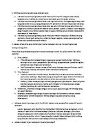
1.1 Name of each part and its function
5
1
4 2
3
6
11
7
10 9
8
10
Machine Translated by Google 1. Name of each part and its function
ÿ Name and function of each part ÿ Warning label ÿ Mounting hole ÿ Heat sink ÿ Operation panel ÿ Rating plate ÿ Power terminal (3P) Power supply to the elevator door controller. ÿ Synchronous motor connection terminal (4P) Connect the synchronous motor. ÿ RS232C port (RJ45) Connect the optional remote operation unit. ÿEncoder input terminal (9-pin D-sub connector) Connect the encoder for position detection. ÿ Control circuit output terminal (7P) is a relay output terminal. The set parameter value is different, the output function is also different. ÿ Control circuit input terminal (10P) It is the terminal for open action command input, close action command input and multi-function input. The multi-function input has different input functions due to different parameter values set.
11
Machine Translated by Google 1. Name of each part and its function
12
Machine Translated by Google
2 Install
2.1 Safety Precautions ................................................ ................................ 14 2.2 Precautions during installation ................................ ...............................................15 2.3 Dimensional Drawings... ...................................................... ................................ 17
13
Machine Translated by Google 2. Installation
2.1 Safety Precautions
•Please install it on non-flammable objects such as metal. Otherwise, a fire may occur. •Do not place near flammable objects. Otherwise, a fire may occur. •Do not hold the terminal cover when transporting.
Otherwise, it may fall and cause personal injury. •Do not allow foreign objects such as metal pieces to enter. Otherwise, a fire may occur. •According to the instruction manual, the installation site should be able to bear the weight of the equipment. Otherwise, it may fall and cause personal injury. •Do not install or operate the elevator door controller with damage or missing parts. Failure to do so may cause an accident.
14
Machine Translated by Google 2. Installation
2.2 Precautions during installation ÿ Do not install in the following places. · Places exposed to direct sunlight. ·A place with high water vapor and humidity. ·A place where oil mist, dust and cotton dust are floating.•Where it will be splashed by wind, rain, water droplets, and oil droplets. · Places with corrosive gas, explosive gas and flammable gas. ·Installed on flammable materials such as wood or near flammable objects. · Places subject to frequent vibrations.
ÿ Do not allow the ambient temperature to exceed the allowable ambient temperature.
The higher the ambient temperature, the shorter the lifespan. Please do not install it near a device that generates a large amount of heat, and fully study the installation location and cooling method. • Allowable ambient temperature: -10ÿ+50ÿ (The measurement point of ambient temperature should be 5cm away from the body)
ÿ Please install vertically or horizontally. When installed horizontally, the cooling effect of the elevator door controller will be reduced. Refer to "11.1 Ratings" (page 104) before use. Use under non-rated values will cause malfunction.
• Vertical installation
• Horizontal installation
× Horizontal installation
15
Machine Translated by Google 2. Installation
ÿ Space required for installation To ensure the ventilation space required for cooling and the space required for wiring, be sure to leave the installation space as shown in the figure below.
ÿ Applicable mounting screws and tightening torques
Applicable mounting screws: Spring screws with M4 flat washers Tightening torque: 1.2N m Elevator door controller installation part thickness: 8mm
16
Machine Translated by Google 2. Installation
2.3 Dimensions 240 230 220
60 2-ÿ5
8
2-5×6.5 (waist hole)
17
Machine Translated by Google
Machine Translated by Google
3 Wiring method
3.1 Safety Precautions ................................................ ................................ 20 3.2 Wiring of the main circuit ................................ ...................................................... 21 3.3 Wiring of the control circuit...................................................... ...................... twenty three
19
Machine Translated by Google 3. Wiring method
3.1 Safety Precautions
•Be sure to cut off the input power before wiring. Please set the input power to OFF (Off) Do wiring work after 5 minutes. Otherwise, electric shock and fire may result. •Be sure to connect the ground wire. Otherwise, electric shock and fire may result.
•Please entrust an electrical engineer to perform wiring work. Otherwise, electric shock and fire may result. •Be sure to install the main unit before wiring. Otherwise, electric shock may result.
•Please confirm that the rated voltage of the product is consistent with the voltage of the AC power supply. Otherwise, a fire may occur. •Do not connect AC power to the output terminals (U·V·W). Otherwise, a fire may occur. •Please connect the wiring of motor and encoder correctly. Otherwise, unpredictable movements such as reversal or sudden acceleration may occur. •Please connect the wiring of the control terminal correctly.
Otherwise, unpredictable actions may result. •Tighten the terminal screws with the specified tightening torque. Inadequate connections may cause heat, smoke, or unexpected behavior. •To prevent the terminal block from falling off and disconnecting, do not apply stress to the wiring. Inadequate connections may cause heat, smoke, or unexpected behavior.
20
Machine Translated by Google 3. Wiring method
3.2 Wiring of the main circuit
3.2.1 Wiring diagram of main circuit
ÿ Main circuit wiring diagram
Main circuit power input Inverter output ÿ Function of main circuit terminals terminal symbol terminal symbol L.N
Terminal name
Terminal function description
The main circuit power input is connected to the power frequency power supply.
Main circuit power input
It is the terminal for grounding. Protective grounding
Earth resistance 100 ÿ or less U, V, W inverter output
Connect the synchronous motor.
Inverter output
It is the terminal for grounding. Protective grounding
Earth resistance 100 ÿ or less
twenty one
Machine Translated by Google 3. Wiring method
3.2.2 Precautions when wiring the main circuit
ÿ Precautions for wiring In order to avoid wrong wiring and operation, please pay attention to the following. (Otherwise it may cause equipment damage) Be sure to connect the power supply to the main circuit power input terminals (L, N), and the motor to the synchronous motor connection output terminals (U, V, W).•The terminals for power supply and motor wiring must be round crimp terminals with sleeves. Please select crimp terminals according to wire size and screw size. • After wiring the main circuit, be sure to confirm the tightness. ·When connecting directly below a large-capacity power transformer (500kVA or more), be sure to install an AC reactor on the input side of the elevator door controller.
• The recommended wire for the main circuit is a 600V type 2 vinyl insulated wire with a continuous maximum allowable temperature of 75°C.•If the overcurrent trip of the circuit breaker for wiring is completely electromagnetic, overheating will occur due to high harmonics, so please select a load factor of 50% or less. • When using an existing motor breaker, remove it.•When inputting, be sure to connect a protective device against overcurrent, short circuit, leakage, etc.•The protective grounding (PE) terminal should be grounded with a grounding resistance of 100ÿ or less.
ÿ Connection device, wire size and tightening torque circuit breaker for wiring Applicable motor output
wire size
(MCCB) Rated current value
0.2kW
5A
0.4kW
10A
Terminal screw size Tightening torque
L, N, U, V, W ground wire 2
2 mm
(AWG14)
(AWG14)
· Screwdriver: Small ÿ screwdriver (blade tip thickness: 0.4mm/blade tip width: 2.5mm)
twenty two
2
2 mm
M2.5
0.4 N m
Machine Translated by Google 3. Wiring method
3.3 Wiring of control circuit 3.3.1 Terminal arrangement diagram and function of each terminal
ÿ Terminal arrangement diagram
Encoder input control circuit output control circuit input
ÿ Function of encoder input terminal (P-IN)
needle arrangement
1
0V terminal
2
A-phase input signal input terminal
3, 4 Not used 5
Related parameters
Terminal function
Needle No.
+24V output terminal
No. -
H006 -
-
(The elevator door controller is supplied to the encoder)
6
Input terminal for B-phase input signal
H006
7
Input terminal for Z-phase input signal
H006
8, 9 Not used
-
Note) Do not use terminals 1 (0V terminal) and 5 (+24V output terminal) for non-encoder power supplies. Also, don't ground. Incorrect connection may result in damage to the elevator door controller.
twenty three
Machine Translated by Google 3. Wiring method
ÿ Functions of control circuit output terminals Terminal No.
Terminal function
Related parameter No.
A1 Relay contact RY1 output terminal (NO: ex-factory)
P033
C1 Relay contact RY1 Output terminal (COM)
P033
A2 Relay contact RY2 output terminal (NO: ex-factory)
P034
C2 Relay contact RY2 Output terminal (COM)
P034
A3 Relay contact RY3 output terminal (NO: ex-factory)
P035
B3 Relay contact RY3 output terminal (NC: ex-factory)
P035
C3 Relay contact RY3 Output terminal (COM)
P035
Note) Common terminals C1, C2, and C3 are independent in the internal circuit. Do not ground this common terminal.
ÿ Functions of control circuit input terminals Terminal No.
Terminal function
Related parameter No.
-
1 Common terminal of input signal (2~9) 2 Input terminal for open command signal 3 Input terminal for closing command
4 Input terminal of multi-function control signal SW1
P026, P027, P038, P039
5 Input terminal of multi-function control signal SW2
P026, P028, P038, P039
6 Input terminal of multi-function control signal SW3
P026, P029, P038, P039
7 Input terminal of multi-function control signal SW4
P026, P030, P038, P039
8 Input terminal of multi-function control signal SW5
P026, P031, P038, P039
9 Input terminal of multi-function control signal SW6
P026, P032, P038, P039
10 Common terminal of input signal (2ÿ9) Note) Common terminals 1 and 10 are connected internally. Do not ground this common terminal.
twenty four
-
Machine Translated by Google 3. Wiring method
3.3.2 Common Precautions for Control Circuits
ÿ Precautions when wiring •For the wiring of the control circuit terminals, please strip the outer sheath of the wire according to the specified size before use.
• Loosen the terminal screws, insert the wires, and tighten with the specified tightening torque. · Twist and twist the stripped wires before wiring to avoid unevenness. Also, do not perform soldering deal with. Bar crimp terminals are recommended. •If the tightening is loose, the wires may fall off, resulting in malfunction. If it is over-tightened, the screws and the unit may be damaged. cause a short circuit and cause a malfunction. ·Use shielded wires for control signal wires, and wire them separately from power wires or strong current circuits. (more than 20cm) ·The wiring length of the control signal line should be less than 30m. · Since the input signal of the control circuit is a small signal, in order to prevent poor contact during contact input, please use the Use the terminal dedicated to the micro signal.
ÿ Wire size and control circuit terminal tightening torque Tightening torque
Terminal symbol
Screw size
Nm
Control output terminal
A1, C1, A2, C2
M2
0.2
wire size
0.25ÿ 0.75mm2 (AWG24ÿAWG18)
A3, B3, C3 Control input terminal
M2
1 to 10
0.2
0.25ÿ 0.75mm2 (AWG24ÿAWG18)
·Screwdriver: small ÿ screwdriver (Blade tip thickness: 0.4mm/Blade tip width: 2.5mm)
25
Machine Translated by Google 3. Wiring method
3.3.3 Precautions related to control input and output circuits
ÿ Control circuit input terminal (terminal No.1 to 10) ·The input circuit is shown in the figure below. Be careful with back current and leakage current.
• Since the internal circuit is powered by the internal power supply +24V, do not supply power from the outside. If a voltage is applied, will cause malfunction. • Connect no-voltage contact signal or open-collector signal to control circuit terminals No. 2 to 9. • Common terminals 1 and 10 are internally connected. Do not ground the common terminal.
ÿ Input Specifications (Terminal No.1 to 10) project
Specification
Open command input × 1 point, Close command input × 1 point Enter the number of points
Multi-function input × 6 points (select and set by parameters) input type
source type
Internal supply voltage
24V DC -10%, +15%
input impedance
About 3.9kÿ
26
Machine Translated by Google 3. Wiring method
ÿ Control circuit output terminals (terminal No.A1, C1, A2, C2, A3 to C3)
ÿ Output Specifications (Terminal No.A1, C1, A2, C2, A3 to C3) project
Specification
output points
Relay 3 points, multi-function output (select and set by parameter)
Contact configuration
1a×2 points, 1c×1 points
Rated control capacity
1 A 230 V AC, 1 A 30 V DC (resistive load)
Contact maximum allowable voltage
250V AC, 30V DC
Mechanical life
More than 10 million times (on-off frequency 180 times/min) More than 100,000 times (1c NC contact is more than 50,000 times, when the rated control capacity is
Electrical life off frequency 20 times/min)
27
Machine Translated by Google 3. Wiring method
3.3.4 Notes on Encoder Input Circuit ÿ Wiring of encoder input terminals (P-IN terminals No.1 to 9) •Set the cable length of the encoder to "1m or less". ·Do not use terminals 1 (+24V output terminals) and 5 (0V terminals) for non-encoder power supplies. Also, do not take land. Incorrect connection may result in damage to the elevator door controller.
ÿ Applicable encoder specifications project
Specification
Incremental, output phase: A phase, B phase, Z phase, appropriate types
Output form: NPN open collector output voltage
24V DC -10%/+15%, 0.1A max
input resistance
About 3.9kÿ
responding speed
Below 20 kHz
Minimum input pulse width
25ÿs
28
Machine Translated by Google 3. Wiring method
ÿ Use the maximum input pulse frequency and minimum input pulse width under the following conditions. Maximum input pulse frequency (1/T): 20kHz or less Phase difference (t1): 12.5ÿs or more, overlap (t2): 12.5ÿs or more
Pulse width (t3): 25ÿs or more
29
Machine Translated by Google 3. Wiring method
30
Machine Translated by Google
4 Operation panel
4.1 Functions of the operation panel...................................................... ................................ 32 4.2 Switching the operation mode ................................ ............................................... 33
31
Machine Translated by Google 4. Operation panel
4.1 Functions of the operation panel
ÿ Name and function of each part each part name
Function overview
In signal display mode, the type of signal on the LED display is displayed. Please refer to parameter number P021.
OA:Open Arrival CA:Close Arrival A:Encoder ÿ Representation when the signal is displayed
A phase signal B:Encoder B phase signal
The display contents of each mode are
ÿ Display part
as follows. ·Output frequency, current, signal, abnormal state and other action status, set frequency, rotation direction, parameter number, value
•Mode switching
MODE key •Reset from parameter setting state and monitoring state to mode display
•Switching between each setting mode and monitoring mode •Determining the setting value (The parameter No. increases and returns to the
SET key mode display.) •Current display switching, signal status display switching •Long press: switch to parameter No. of custom mode .set up
•Change of parameter No., monitor No.
ÿ ÿ(UP)
•Change of set value
keyÿ(DOWN) key
RUN key
•Start of operation •Stop of operation
STOP key
•Reset of abnormal state •Reset after completion of door width measurement, start-up positioning operation, and completion of auto-tuning
32
Machine Translated by Google 4. Operation panel
4.2 Switching of operating modes ÿ Functions of operating modes model
ÿOperation status display mode
ÿFrequency setting mode
Description of the mode
Panel Display Example
Display output frequency and output current. It is also possible to switch to the signal display.
Digital setting of frequency and frequency command can be monitored.
It is possible to set the rotation direction of the panel operation ÿRotation direction and monitor the control status (panel/external input). setting mode
ÿControl status Control status and abnormal content can be monitored. monitoring mode
ÿCustom setting mode
10 frequently used parameters can be registered, and data can be changed and monitored.
ÿParameter Parameters can be monitored and changed. Change in the order setting value of P, H, d. mode
(when P parameter)
ÿ Switching of operating modes ·Press the [MODE] key to switch between various modes in turn. ·Press the [SET] key in each mode to enter the state where data can be monitored or changed. Press the [MODE] key to return to the original screen. When pressing the [SET] key by mistake, you can press the [MODE] key to return.
33
Machine Translated by Google 4. Operation panel
Note 1) The display changes according to the value of parameter "P021: Quick monitor selection". Note 2) In frequency setting mode and rotation direction setting mode, it is displayed only when the value of parameter "P004: Control mode selection" is "0".
34
Machine Translated by Google
5 Control status monitoring
5.1 List of control status monitoring items...................................................... ..........36 5.2 Introduction of each monitoring number ................................................ ................................. 37
35
Machine Translated by Google 5. Control status monitoring
5.1 List of control status monitoring items The following items can be monitored in the control status monitor mode. Monitoring No.
Monitoring items
n001 Output frequency
unit
Display content
Hz is displayed in 0.1Hz units
n002 output current
A is displayed in 0.1A units
n003 Output voltage
VAC is displayed in 1VAC units
n004 Internal DC voltage
VDC is displayed in 1VDC units
n005 set frequency
Hz is displayed in 0.1Hz units
n006 Detection frequency
Hz is displayed in 0.1Hz units
n007 Door position field
- 0 to 9
n008 Door position
- 1ÿ65535
n009 Open arrival position data
- 1ÿ65535
n010 Door opening and closing times
Times 1ÿ65535
n011 Encoder detection status
- F: Forward rotation, r: Reverse rotation
n012 Abnormal display (latest)
- Display the latest abnormal content
n013 Abnormal display (1 time ago)
- Display the content of the abnormality one time ago
n014 Abnormal display (2 times ago)
- Displays the content of the abnormality 2 times before
n015 Abnormal display (3 times ago)
- Displays the content of the abnormality 3 times ago
n016 Input signal status
- Display contact data
n017 Output signal status
- Display contact data
n018 Cumulative start time n019 Cumulative running time n020 Intrusion detection status
n021 Encoder pulse number n022 version information
36
-
pulse - show main version
Machine Translated by Google 5. Control status monitoring
5.2 Introduction of each monitoring number
n001 output frequency Displays the output frequency. "0.0" is displayed during stop.
n002 output current output internal DC voltage voltage display n003
n004
output current, output
voltage, internal DC voltage. The displayed contents are not suitable for precision measurements. Please use only as a reference value. (When precise numerical values are required, please use a separate measuring instrument.)
n005 set frequency display set frequency.
The n006 detected frequency detects the actual motor speed through the encoder signal. The frequency value calculated from the detected motor speed is displayed as the detected frequency.
Encoder pulses per minute [p/min] Encoder Motor speed [r/min]= constant [p/r]
Number of motor poles
×Motor speed [r/min]
Detection frequency [Hz]=
120
Note 1) The number of motor poles (parameter H005) and the encoder constant (parameter H006) must be set.
n007 Door position field shows the action field of the door position. "0": closed hold motion area, "1 to 4": open motion area "5": open hold motion area, "6 to 9": closed motion area
37
Machine Translated by Google 5. Control status monitoring
n008 Door Position Displays the data value of the door position. Data range: 1ÿ 65535 Operation panel display: 00.01ÿ655.3
n009 open arrival position data Displays the door position data when the OPEN arrival signal changes from OFF to ON. Data range: 1ÿ65535 Operation panel display: 00.01ÿ655.3
n010 Door opening and closing times A maximum of 65,535 door openings and closings can be monitored. Data range: 1ÿ65535 Operation panel display: 00.01ÿ655.3 Set the data of parameter P037 (setting data clear) to "4" to clear the data of switching times.
n011 The encoder detection state shows the pulse frequency of the encoder signal. The rotation direction of the motor can also be displayed using the encoder signal. F: Forward rotation (opening action), r: reverse rotation (closing action)
n012 Error display (latest) n013 Error display (1st (2nd time time ago) ago) ErrorError display display n014
(3rd time ago) Displays the
n015
latest, 1st to 3rd previous
error information.
38
Machine Translated by Google 5. Control status monitoring
n016 Input signal status n017 output signal status The status of the input signal and output signal of the control circuit terminal can be monitored by "on/off of each LED segment". state.
n016: Input signal status On: The input terminal and the common terminal are closed Off: The input terminal and the common terminal are in an open state Note) The input signal display lights up when the input terminal is closed, and goes out when the input terminal is open.
It does not turn on when the input signal is ON and turn off when it is OFF.
n017: output signal status On: The relay coil is in the excitation state Off: The relay coil is in a non-excited state
39
Machine Translated by Google 5. Control status monitoring
n018 Cumulative start time Displays when the elevator door controller is powered on. Display unit is 1 hour = "0.001". After "10.00", it is displayed as "0.01" in units of 10 hours; after "100.0", it is displayed as "0.1" in units of 100 hours; after "1000", it is displayed as "1" in units of 1000 hours. Since there are some errors in the displayed content, please use it as a reference value.
1 hour to 9999 hours (in units of 1 hour)
10,000 hours to 99,990 hours (in units of 10 hours)
100,000 hours to 999,900 hours (in units of 100 hours)
1 million hours to 9,999,000 hours (in units of 1,000 hours)
40
Machine Translated by Google 5. Control status monitoring
n019 Cumulative running time
Display the drive motor time on the elevator door controller. Display unit is 1 hour = "0.001". After "10.00", it is displayed as "0.01" in units of 10 hours; after "100.0", it is displayed as "0.1" in units of 100 hours; after "1000", it is displayed as "1" in units of 1000 hours. Since there are some errors in the displayed content, please use it as a reference value.
1 hour to 9999 hours (in units of 1 hour)
10,000 hours to 99,990 hours (in units of 10 hours)
100,000 hours to 999,900 hours (in units of 100 hours)
1 million hours to 9,999,000 hours (in units of 1,000 hours)
41
Machine Translated by Google 5. Control status monitoring
n020 sandwich detection state Displays the trapping detection status during gate control. When there is no clamping, "---" is displayed.
Display switch status Display clip detection type
O open action C
Overload
C close action S Switch state sandwich detection type
torque slip
t E
n021 encoder pulse number Displays the pulse number of the encoder. The display unit is 1 pulse=0.01. When the pulse number of the encoder is 1024 pulses, "10.24" is displayed.
The n022 version information shows the version of the elevator door controller.
42
detection hours safety sensor
Machine Translated by Google
6 parameter setting
6.1 Parameter setting (parameter setting mode) ...................................... ......44 6.2 Assignment of parameter No. (custom setting mode) ......................48 6.3 Parameter Setting (Custom Setting Mode) .................................50 6.4 List of P field parameters...................................................... ................................. 51 6.5 List of H field parameters................................. ............................................... 53 6.6 d Domain Parameters At a Glance ................................................ .................55
43
Machine Translated by Google 6. Parameter setting
6.1 Parameter setting (parameter setting mode) Parameters can be monitored and set in "custom setting mode" and "parameter setting mode". Please change or set each function parameter during stop. Some function parameters can also be changed during operation.
6.1.1 Setting and changing function parameters during stop
ÿSetting example When the maximum output frequency is changed from 50.0Hz to 60.0Hz (the data of parameter P005 is changed from "50.0" to "60.0") 1. Press the key to stop the elevator door controller.
2. Press the key to change to the P field parameter setting mode. (When setting a password,
Password is required. Please refer to parameter P036: Password item)
3. Press
key to change the parameter No. to P005.
4. Press the key to display the data of parameter P005. (display flashes)
5. Press
key to set the data display value to "60".
(display flashes)
6. Press the key to set the data.
7. Press the key to enter the operation ready state. It becomes a normal stop state, and the operation of the elevator door controller can be performed. (action status display mode)
44
Machine Translated by Google 6. Parameter setting
·After setting and changing the data, the setting data is written into the non-volatile memory inside the elevator door controller, and it is retained even in the event of a power failure. ·When changing parameters that cannot be set during operation, if the operation signal is ON, "P.Err" will flash and display, and return to the parameter number display after 2 seconds. Start operation without changing parameters.
45
Machine Translated by Google 6. Parameter setting
6.1.2 Setting and changing function parameters during operation
When data is changed during operation, the motor and motor load may change greatly, or it may start and stop suddenly. Please fully confirm the safety before use.
For the function parameters that can be changed during operation, refer to the list of each parameter.
ÿSetting example When changing the 1st deceleration time from 5.0 seconds to 10.0 seconds (change the data of parameter P002 from "5.0" to "10.0")
Use the current data to control the motor 1. Confirm the operation status. (during 50.0Hz operation)
2. Press the key to change to the P field parameter setting mode. (When setting a password,
Password is required. Please refer to parameter P036: Password item)
3. Press
key to change the parameter No. to P002.
4. Press the key to display the data of parameter P002. (display flashes)
5. Press
flashing)
46
key, the data display value is changed to "10.0". (display section
Machine Translated by Google 6. Parameter setting
Control motors with new data
1. Press the key to set the data.
2. Press the key to enter the action status display mode.
(If the key is not pressed, the display will not be switched)
•When the parameter that cannot be set during operation is displayed during operation, if the operation signal is turned OFF, after the set value flashes, the data can be set.
47
Machine Translated by Google 6. Parameter setting
6.2 Assignment of parameter No. (custom setting mode) In the "custom setting mode", up to 10 functional parameters that need to be changed frequently can be selected arbitrarily, so as to realize the change of data more easily. Custom parameter No. can be assigned from 1 to 10. Also holds during power outages.
ÿSetting example Change the parameter assigned to the custom setting parameter "U001" from "P001" (1st acceleration time) to "P002" (1st deceleration time). 1. Stop state or running state (during 50.0Hz operation)
2. Press the key to change to "custom setting mode".
3. Press the key to confirm the currently assigned function parameter No.. *The function parameter No. in the custom setting mode is displayed with dots after the symbols "P" and "d". (When setting a password, the password must be entered. Please refer to parameter P036: Password) 4. Press and hold the key for 2 seconds to enter the allocation setting state. (digital part flashes)
5. Press
key to change the parameter No. to P.002.
6. Press the key to complete the parameter No. assignment.
48
Machine Translated by Google 6. Parameter setting
The initial settings of custom parameters No.1 to 10 are shown in the table below.
Custom parameter No. Function parameter No.
function name
initial value
U001
P003
Operation command selection
0
U002
P004
Control mode selection
0
U003
P021
When quick monitoring
0
selects the open action
U004
d053
300 When the jamming detection judgment time is closed
U005
d054
300 When the trapping detection judgment time is activated
U006
d044
0 When overload detection judgment time is closed
U007
d049
0 Overload detection judgment time
U008
d057
Startup confirmation time
U009
d028
open to holding torque level
150.0
600
U010
d029
closed to the holding torque level
150.0
To restore the assignment settings of custom parameters No.1 to 10 to the initial state, please set the function parameter The set value of "P037: Setting data clear" is set to "3". (The value of the data does not change.)
•Only the data can be displayed for the function parameters that cannot be changed during operation.
49
Machine Translated by Google 6. Parameter setting
6.3 Parameter setting (custom setting mode) Set, change, and check the function parameter data assigned to the custom setting parameter No. For the function parameters that can be changed during operation, refer to the list of each parameter.
When data is changed during operation, the motor and motor load may change greatly, or it may start and stop suddenly. Please fully confirm the safety before use.
ÿSetting example When the data of "P002" (1st deceleration time) assigned in the custom setting parameter "U001" is changed from "5.0" to "10.0"
1. Stop state or running state (during 50.0Hz operation)
2. Press the key to change to "custom setting mode".
3. Press the key to confirm the currently assigned function parameter No.. *The function parameter No. in the custom setting mode is displayed with dots after the symbols "P" and "d". (When setting a password, the password must be entered. Please refer to parameter P036: Password) 4. Press the key to display the data of parameter P002. (display flashes)
5. Press
key to set the data display value to "10.0".
(display flashes) 6. Press the key to set the data. If the data is changed during operation, it will operate with the new data.
•For function parameters that cannot be changed during operation, only this data can be displayed.
50
Machine Translated by Google 6. Parameter setting
6.4 List of P field parameters No.
running function name
Predetermined area
Synchronize
asynchronous
initial value
initial value
unit
can be changed
P001 1st acceleration time
• 0·0.1ÿ999.9
0.1[sec]
0.5
0.5
P002 1st deceleration time
• 0·0.1ÿ999.9
0.1[sec]
0.5
0.5
0
P003 Operation command selection
0ÿ2
-
0
P004 Control mode selection
0ÿ5
-
0
P005 Maximum output frequency
0.5ÿ250.0
0.1[Hz]
P006 Lower limit frequency
0.5ÿ250.0
0.1[Hz]
P007 Upper limit frequency
0.5ÿ250.0
0.1[Hz] 250.0
P008 Maximum output voltage
• 0 • 1ÿ500
P009 Stop Mode
•0•1 0.5ÿ60.0
P010 Stop frequency P011 Select current thermal function
•0•1•2•3
P012 Set thermal current
• 0.1ÿ100.0
P013 Overcurrent stall prevention function
•0•1
P014 Overvoltage stall prevention function
•0•1
twenty four
0
0 50.0 0.5 250.0
1[V]
100
-
0
0
0.5
0.5
0.1[Hz] -
0
2
2
1.4
3.6
-
1
1
-
1
1
0.0
0.0
0
0.1[A]
P015 Current limit function
0.0 • 0.1ÿ10.0 0.1[sec]
P016 Start mode
0•1•2•3
-
0
P017 Instantaneous stop and restart selection
0•1•2
-
0
0
P018 Standby time
0.1ÿ999.9
0.1
0.1
0
0
P019 Choose to try again
•0•1•2•3
P020 Retry times
• 1ÿ10
P021 Quick monitoring selection
•0•1
P022 Display selection
•0•1
P023 Line speed override
• 0.1ÿ100.0
P024 OCS level
• 1ÿ200
0.1[sec] -
1 time] -
1
1
0
0
0
0
0.1
7.5
7.5
1[%]
140
140
P025 carrier frequency
5ÿ15
1[kHz]
8
10
P026 Input signal logic setting
0ÿ63
-
2
27
P027 SW1 function selection
0ÿ16
-
1
1
P028 SW2 function selection
0ÿ16
-
2
2
P029 SW3 function selection
0ÿ16
-
0
0
P030 SW4 function selection
0ÿ16
-
0
3
P031 SW5 function selection
0ÿ16
-
0
4
P032 SW6 function selection
0ÿ16
-
0
0
51
Machine Translated by Google 6. Parameter setting
No.
running function name
Predetermined area
Synchronize
asynchronous
initial value
initial value
unit
can be changed
P033 RY1 function selection
• 0ÿ17, r0ÿr17
-
r10
r10
P034 RY2 function selection
• 0ÿ17, r0ÿr17
-
r11
r11
P035 RY3 function selection
• 0ÿ17, r0ÿr17
-
4
4
P036 Password
• 0000 • 1ÿ9999
0
0
1
0•1•2•3•4-
P037 Setting data clear P038 Safety Sensor Response Time
• 0 • 1ÿ9999
1[msec]
P039 Input signal response time
• 0 • 1ÿ9999
1[msec]
P040 Overspeed judgment torque
• 0.0ÿ200.0
0.1[%]
0
0
10
10
10
10
150.0
150.0
0•1•2
-
P041 S-shaped acceleration and deceleration function
0
0
P042 V/F Mode
50•60•FF
-
FF
50
P043 V/F curve
0•1
-
0
0
1[%]
15
15
• 0ÿ40
P044 Torque boost P045 base frequency
45.0ÿ250.0
0.1[Hz]
50.0
50.0
P046 DC braking time
0.0ÿ120.0
0.1[sec]
0.5
0.5
P047 DC brake level
0ÿ100
1[%]
0
0
P048 RS232C communication protocol selection*1
0•1•2
-
0
0
192
192
*1
48 •96 •192 •384 [bps]
P049 RS232C communication speed
P050 RS232C stop bit*
*1
1•2 0•1•2
P051 RS232C Parity*1
[bit]
1
1
-
0
0
0.0
0.0
0.0 • 0.1ÿ60.0 0.1[sec]
P052 RS232C timeout detection*1 *1
1ÿ9999
1[msec]
1
1
P054 RS232C TEXT completion judgment time*1
3ÿ200
1[msec]
5
5
P055 Parameter backup and read
0 • rEAd • rEco.
-
0
0
P056 Low voltage prevents heavy hammer from hitting the door
0•1
-
0
0
P057 Low voltage anti-collision door resistance adjustment frequency
0ÿ100
1[msec]
15
15
0.1[Hz]
2.0
2.0
1[%]
10
10
-
1
1
1[sec]
0
0
-
1
1
P053 RS232C message sending waiting time
P058 Low voltage anti-collision door limit frequency float • 0.5ÿ250.0 P059 Torque boost when door is closed
• 0ÿ40
P060 Action selection after encoder error reset
0•1
P061 Door open overtime alarm
0 • 1ÿ60
P062 Emergency door opening deceleration selection
0•1
*1: When the parameters are P048 to P054, the changed parameter values will take effect when the power is turned from OFF to ON.
52
Machine Translated by Google 6. Parameter setting
6.5 List of H field parameters H field parameters are immutable in the overall operation. No.
function name
Predetermined area
Synchronize
asynchronous
initial value
initial value
unit -
2
0
1[V]
50
200
0.0ÿ100.0
0.1[A]
1.4
3.6
0.5ÿ250.0
0.1[Hz]
H001 Motor selection
1•2•3•4
H002 Motor rated voltage
0ÿ250
H003 Motor rated current H004 Motor rated frequency
twenty four
50
2 • 4 • 6 • 8 • 10 • H005 Number of motor poles [pole]
12 •
-
16
6
1024
1024
14 • 16 • 18 • 20
H006 Encoder constant
50ÿ10000
H007 Motor rotation direction setting
0•1
-
1
1
H008 Autotune
0•1•2•3
-
0
0
H009 Encoder offset value
0ÿ359
340
340
H010 Phase-to-phase resistance
0.00ÿ99.99
0.01[ÿ]
11.27
11.27
1[p/r]
1[°]
H011 d-axis inductance
0.0ÿ99.99
0.01[mH]
27.96
27.96
H012 q-axis inductance
0.0ÿ99.99
0.01[mH]
28.23
28.23
H013 D-axis current proportional increase
0ÿ32000
-
71.1
71.1
H014 D-axis current integral increase
0ÿ32000
-
228.9
228.9
H015 q-axis current proportional increase
0ÿ32000
-
72.1
72.1
H016 q-axis current integral increase
0ÿ32000
-
228.9
228.9
H017 ASR proportional
0ÿ100.0
-
increase 1 H018 ASR integral
0ÿ100.0
time 1 H019 ASR proportional increase 0ÿ100.0 when 0Hz is held
0•1
H022 Start action selection 0 1 when power is restored H023
Start positioning operation abnormal judgment
-
0.0ÿ999.9
5.0
5.0
0.5
0.5
5.0
5.0
0.5
0.5
-
1
1
-
1
1
0.1[sec]
0
0
0.01[sec]
0.1[sec]
H020 0Hz hold ASR integral time 0ÿ100.0 H021 Startup finished mode selection
0.1[sec]
time
H024 Encoder error detection time
0.0 • 0.1ÿ2.0
1.0
1.0
H025 Encoder frequency multiplication setting
0•1
-
0
0
H026 ASR Amplification Switch Setting
0•1•2
-
0
0
H027 ASR Scale Increase 2
0ÿ100.0
-
5.0
5.0
H028 ASR integration time 2
0ÿ100.0
0.5
0.5
0.1[sec]
53
Machine Translated by Google 6. Parameter setting
No.
function name
Predetermined area
Synchronize
asynchronous
initial value
initial value
unit -
H029 ASR ratio increase by 3
0ÿ100.0
H030 ASR integration time 3
0ÿ100.0
H031 ASR ratio increase by 4
0ÿ100.0
5.0
5.0
H032 ASR integration time 4
0ÿ100.0
0.1[sec]
0.5
0.5
H033 ASR boost switching frequency 1
0.5ÿ50.0
0.1[Hz]
2.0
2.0
H034 ASR boost switching frequency 2
0.5ÿ50.0
0.1[Hz]
5.0
5.0
H035 Start positioning action voltage
10ÿ60
1[V]
45
45
-
2
2
-
0
0
H036 Reverse rotation when starting positioning and try again 0 1 2
H037 Encoder Z-phase input logic setting 0•1
0.1[sec] -
-
5.0
5.0
0.5
0.5
2
2
H039 Frequency at synchronous start
0.5ÿ250.0
0.1[Hz]
4.0
4.0
H040 Synchronous starting torque
0.0ÿ300.0
0.1[%]
150.0
150.0
0.01[sec]
0.0
0.0
H042 Slip judgment at synchronous start % 0.0ÿ100.0
0.1[%]
70.0
70.0
H043 Slip judgment time at synchronous start 0ÿ9999
1[msec]
200
200
-
0
0
H038 Synchronization/positioning start mode selection 0•1•2
H041
Encoder error detection at synchronous start
0.0 • 0.1ÿ2.0
Time
H044 H parameter password
54
0ÿ9999
Machine Translated by Google 6. Parameter setting
6.6 d field parameter list
No.
running
Synchronize
asynchronous
initial value
initial value
set range unit
function name can be changed
-
655.3
655.3
d001 Door width setting value
• 0ÿ65535
d002 Close arrival position
• 0.00ÿ100.0
0.01[%] 4.00
4.00
d003 Open speed change
• 0.00ÿ100.0
0.01[%] 15.00
15.00
position 1 d004 Open speed
• 0.00ÿ100.0
0.01[%] 40.00
40.00
change position 2 d005 Open
• 0.00ÿ100.0
0.01[%] 68.00
68.00
speed change position 3 d006
• 0.00ÿ100.0
0.01[%] 96.00
96.00
Open reach position d007 Close
• 0.00ÿ100.0
0.01[%] 85.00
85.00
speed position 1 d008 Close speed position 2
• 0.00ÿ100.0
0.01[%] 60.00
60.00
d009 Close speed position 3
• 0.00ÿ100.0
0.01[%] 34.00
d010 Close arrival hold frequency
• 0.0ÿ250.0
0.1[Hz]
1.8
2.0
d011 Open frequency 1 d012
• 0.5ÿ250.0
0.1[Hz]
5.0
2.0
Open frequency 2 d013 Open
• 0.5ÿ250.0
0.1[Hz]
18.0
2.0
frequency 3 d014 Open frequency
• 0.5ÿ250.0
0.1[Hz]
18.0
23.0
4 d015 Open arrival hold frequency
• 0.5ÿ250.0
0.1[Hz]
4.0
3.0
• 0.0ÿ250.0
0.1[Hz]
2.0
3.0
d016 Close frequency 1
• 0.5ÿ250.0
0.1[Hz]
5.0
3.0
d017 Close frequency 2 d018
• 0.5ÿ250.0
0.1[Hz]
15.5
3.0
Close frequency 3 d019 Close
• 0.5ÿ250.0
0.1[Hz]
15.5
19.0
frequency 4 d020 Open
• 0.5ÿ250.0
0.1[Hz]
2.0
2.0
acceleration and deceleration time 1 d021
• 0.0 • 0.1ÿ999.9 0.1[sec]
1.0
0.5
Open acceleration and deceleration time 2
• 0.0 • 0.1ÿ999.9 0.1[sec]
1.0
0.5
d022 Open acceleration and deceleration
• 0.0 • 0.1ÿ999.9 0.1[sec]
0.5
1.2
time 3 d023 Open acceleration and
• 0.0 • 0.1ÿ999.9 0.1[sec]
1.2
1.0
deceleration time 4 d024 Close acceleration
• 0.0 • 0.1ÿ999.9 0.1[sec]
0.7
0.5
and deceleration time 1 d025 Close
• 0.0 • 0.1ÿ999.9 0.1[sec]
1.0
0.5
acceleration and deceleration time 2 d026
• 0.0 • 0.1ÿ999.9 0.1[sec]
0.5
1.0
Close Acceleration and deceleration time 3
• 0.0 • 0.1ÿ999.9 0.1[sec]
1.7
1.0
d027 Close acceleration and deceleration time
• 0.0ÿ300.0
0.1[%]
150.0
150.0
4 d028 Open to reach holding torque level d029
• 0.0ÿ300.0
0.1[%]
100.0
100.0
0.0
0.0
Close to reach holding torque level d030 Open/close holding action stop time • 0.0
• 0.1ÿ999.9 0.1[sec]
34.00
55
Machine Translated by Google 6. Parameter setting
No.
running
Synchronize
asynchronous
initial value
initial value
set range unit
function name can be changed
d031 Hold standby frequency when open
• 0.5ÿ250.0
0.1[Hz]
2.4
0.5
arrives d032 Hold standby frequency when
• 0.5ÿ250.0
0.1[Hz]
2.4
0.5
close arrives d033 Hold standby time when open arrives
• 0.0ÿ10.0
0.1[sec]
0.0
0.0
d034 Hold standby time when closing
• 0.0ÿ10.0
0.1[sec]
0.0
d035 Start the timer
• 0.00ÿ10.00
0.01[sec] 0.00
d036 Close start timer
• 0.00ÿ10.00
0.01[sec] 0.00
d037 Operation frequency when power is ON
• 0.5ÿ250.0
0.1[Hz]
5.0
d038 Door width measurement frequency d039
• 0.5ÿ250.0
0.1[Hz]
5.0
5.0
1.0
0.0
Abnormal detection time when reaching SW d040
0.0 0.30 0.00
0.0 • 0.1ÿ10.0 0.01[sec]
5.0
Overload detection frequency 1 when opening operation
• 0.5ÿ250.0
0.1[Hz]
8.0
10.0
d041 Overload detection frequency 2 during opening
• 0.5ÿ250.0
0.1[Hz]
16.0
50.0
d042 Overload detection current 1 during open action
• 0.1ÿ100.0
0.1[A]
1.4
1.2
d043 Overload detection current 2 during open action
• 0.1ÿ100.0
0.1[A]
1.4
1.2
1[msec]
0
0
• 0.5ÿ250.0 detection frequency 1 during closing action d046 Overload detection frequency 2 during
0.1[Hz]
8.0
10.0
0.5ÿ250.0 closing action d047 Overload detection current 1 during closing•action
0.1[Hz]
16.0
50.0
• 0.1ÿ100.0
0.1[A]
1.4
1.2
• 0.1ÿ100.0
0.1[A]
1.4
1.2
1[msec]
0
0
0.1[%]
50.0
50.0
d044 Overload detection judgment time during open action• 0 1ÿ9999 d045 Overload
d048 Overload detection current 2 during closing action
d049 Judgment time of overload detection during closing action • 0 • 1ÿ9999 d050 Intrusion judgment frequency (low speed)
• 0.0ÿ100.0
d051 Trap judgment frequency (high
• 0.0ÿ100.0
0.1[%]
70.0
70.0
speed) d052 Trap judgment switching
• 0.5ÿ250.0
0.1[Hz]
0.5
5.0
frequency d053 Trap detection judgment time during open operation • 0 ÿ 1ÿ9999
1[msec]
300
100
d054 Intrusion detection judgment time during closing action• 0 ÿ 1ÿ9999
1[msec]
300
100
d055 The level of the maximum moment when the door is clamped
• 0.0ÿ500.0
0.1[%]
250.0
250.0
d056 Standby time after sandwich detection
• 0.0ÿ999.9
0.1[sec]
0.0
0.0
d057 Start confirmation time
• 100ÿ9999
1[msec]
600
200
d058 Overload detection start confirmation
• 100ÿ9999
1[msec]
300
300
time d059 Forced open action judgment time
• 0.0 • 0.1ÿ999.9 0.1[sec]
0.0
0.0
d060 Forced close action judgment time
• 0.0 • 0.1ÿ999.9 0.1[sec]
0.0
0.0
0.0
0.0
d061 Abnormal open/close action forced action time• 0.0 • 0.1ÿ999.9 0.1[sec] d062 Abnormal open/close action open arrival hold time• 0.0ÿ10.0 d063 Prohibited area when sandwich detection is open • 0.00ÿ100.0
56
0.1[sec] 0.01[%] 100.0
0.0
0.0 100.0
Machine Translated by Google 6. Parameter setting
running
No.
function name
asynchronous
initial value
0.01[%]
0.00
0.00
• 0.0ÿ10.0
0.1[sec]
3.0
3.0
• 0.0ÿ10.0
0.1[sec]
3.0
3.0
change d064 Prohibited range during clamping detection and closing action
Synchronize
initial value
set range unit
Can
d067 Stop selection during open/close action
0•1
-
0
0
d068 No signal arrival selection
0•1•2
-
1
1
0ÿ3
-
0
0 0.5
d069
When the terminal is detected / when no signal arrives
Judgment selection d070 Slip arrival judgment frequency
• 0.1ÿ10.0
0.1[Hz]
0.5
d071 Slip arrival judgment time
• 1ÿ9999
1[msec]
200
200
d072 Slip differential switch arrival substitution selection
• 0.0 • 0.1ÿ10.0 0.1[sec]
0.5
0.5
-
1
1
d074 Judgment time of overload detection when open arrives • 0 • 1ÿ9999
1[msec]
0
0
d075 Judgment time of overload detection when closing is reached• 0 • 1ÿ9999
1[msec]
0
0
0.0
0.0
d073 Action selection after terminal detection
d076
When the input terminal is abnormally closed
0•1
• 0.0 • 0.1ÿ999.9 0.1[sec]
Forced open action judgment time
d077 Input terminal abnormal closing action frequency 1 • 0.5ÿ250.0
0.1[Hz]
6.4
6.4
d078 Input terminal abnormal closing action frequency 2 • 0.5ÿ250.0
0.1[Hz]
8.0
8.0
d079 Input terminal abnormal close action frequency 3 • 0.5ÿ250.0 d080
0.1[Hz]
7.2
7.2
Input terminal abnormal close action frequency 4 • 0.5ÿ250.0 Input
0.1[Hz]
5.6
5.6
• 0.0 • 0.1ÿ999.9 0.1[sec]
0.5
0.5
• 0.0 • 0.1ÿ999.9 0.1[sec]
0.5
0.5
• 0.0 • 0.1ÿ999.9 0.1[sec]
0.5
0.5
• 0.0 • 0.1ÿ999.9 0.1[sec]
0.5
0.5
20.0
20.0
0.5
0.5 3.2
d081
terminal abnormal close action Acceleration and deceleration
d082
time 1 Input terminal abnormal closing action
Acceleration and deceleration
d083
time 2 Input terminal abnormal closing action Acceleration and deceleration
d084
time 3 Input terminal abnormal closing action Acceleration and deceleration
time 4 d085 Emergency opening action frequency
• 0.5ÿ250.0
d086 Emergency opening action acceleration and deceleration time
• 0.0 • 0.1ÿ999.9 0.1[sec]
d087 Open low speed action frequency
• 0.5ÿ250.0
0.1[Hz]
3.2
d088 Close low speed action frequency
• 0.5ÿ250.0
0.1[Hz]
3.2
3.2
0.5
0.5
d089 Low-speed action acceleration and deceleration time
0.1[Hz]
• 0.0 • 0.1ÿ999.9 0.1[sec]
d090 Action selection when closing arrival signal is
0•1
abnormal d091 Close arrival signal detection width
0·0.1ÿ10.0
-
0.1[%]
1
1
8.0
8.0
d092 Open deceleration timer
• 0.00ÿ10.00
0.01[sec] 0.00
0.00
d093 Close deceleration timer
• 0.00ÿ10.00
0.01[sec] 0.00
0.00
57
Machine Translated by Google 6. Parameter setting
running
No.
The
d094
asynchronous motor can be changed to reach the holding torque
Synchronize
asynchronous
initial value
initial value
set range unit
function name
0.1ÿ100.0
0.1[A]
0.5
0.5
0.1ÿ100.0
0.1[A]
0.4
0.4
0.1[%]
250.0
250.0
flow
d095
The asynchronous motor is opened to reach the holding torque
flow
d096 Door closing clamping maximum torque level
58
• 0.0ÿ500.0
Machine Translated by Google
7 Initial setting and test operation of the motor 7.1 Safety Precautions ................................................ ................................. 60 7.2 Setting of motor constants ................................ ............................................... 61 7.3 Coding Setting of device constants ...................................................................... .................62 7.4 Trial operation of the motor.................................. ............................................... 63
59
Machine Translated by Google 7. Initial setting and test operation of the motor
7.1 Safety Precautions
•Before turning on the power, confirm that the terminal block or connector is securely installed. Otherwise, electric shock and fire may result. •Be sure to turn on the power after closing the terminal cover. In addition, do not open while power is on terminal cover. Otherwise, electric shock and fire may result. •Do not operate the panel with wet hands. Otherwise, electric shock may result. •When the elevator door controller is powered on, do not touch the terminals of the elevator door controller even in the stopped state. Otherwise, electric shock may result.
•When data is changed during operation, the motor and motor load may change greatly, or it may start and stop suddenly. Please fully confirm the safety before use. After starting auto-tuning, the elevator door controller will automatically apply high voltage DC to the motor electricity, so do not touch. Otherwise, electric shock may result. •When using the auto-tuning function, after pressing the operation key (RUN) on the panel, the elevator door controller automatically drives the motor. Please fully confirm the safety before use.
•The heat sink is in a high temperature state, please do not touch it. Otherwise, burns may occur. •Be sure to adjust and confirm each parameter before operation. Depending on the parameter settings, unexpected actions may occur.
60
Machine Translated by Google 7. Initial setting and test operation of the motor
7.2 Setting of motor constants ÿSetting of motor constants •Set the parameters "H002 to H005" according to the motor used. ·When the setting value of parameter "H001: Motor selection" is "2" "3" "4", the door controller will automatically set Set parameters "H002~H006" and "H010~H016". The set value of "H001: Motor selection" is "1" When the motor is used, please manually set the parameters "H002~H006" and "H010~H012" according to the motor used. Or please use the [H008: Auto tuning] function
ÿSetting of motor rotation direction ·In the initial setting state, when the rotation direction is reversed during operation, please set the parameter "H007: Motor rotation direction" Change the value of "Towards Setting" to "1".
ÿSet the motor constant by auto tuning •Parameters such as phase-to-phase resistance and inductance of each axis necessary for synchronous motor control can be automatically set by executing auto-tuning.
For the steps of auto-tuning, please refer to the item "H008: Auto-tuning".
Types and settings of parameters related to motor constants
function name
Parameter No.
set unit
Predetermined area
0: Asynchronous motor
1: Synchronous motor
H001 Motor selection
-
2: Recommended motor 1 (50W) 3: Recommended motor 2 (50W)
4: Recommended motor 3 (80W)
H002 Motor rated voltage
1[V]
0ÿ250
H003 Motor rated current
0.1[A] 0.0ÿ100.0
H004 Motor rated frequency
0.1[Hz] 0.5ÿ250.0
H005 Number of motor poles [pole]
H007 Motor rotation direction setting
-
-
2 •4 •6 •8 •10 •12• 14 • 16 • 18 • 20 0: Initial setting 1: Reverse setting
H008 Autotune
-
0•1•2•3
H010 Phase-to-phase resistance
0.01[ÿ] 0.00ÿ99.99
H011
0.01[mH] 0.0ÿ99.99
d-axis inductance
61
Machine Translated by Google 7. Initial setting and test operation of the motor
function name
Parameter No.
H012
q-axis inductance
H013
d-axis current proportional increase
H014
d-axis current integral increase
H015 H016
set unit
Predetermined area
0.01[mH] 0.0ÿ99.99
q-axis current proportional increase
q-axis current integral increase
-
0ÿ32000
-
0ÿ32000
-
0ÿ32000
-
0ÿ32000
7.3 Setting of encoder constants ÿEncoder constant setting • Set the resolution and multiplier according to the encoder used.
ÿEncoder constant setting by auto tuning ·If the number of poles is less than 16, please use the motor with 1000ppr or more, and please use the motor with more than 16 poles. Encoders with angular resolutions above 3000ppr. • The parameters of the encoder offset value necessary for synchronous motor control can be automatically set by executing auto-tuning.
For the steps of auto-tuning, please refer to the item "H008: Auto-tuning".
ÿTypes and settings of parameters related to encoder constants ÿ Parameters related to encoder specifications Parameter No.
function name
H006 Encoder constant
set unit
Predetermined area
1[p/r] 50ÿ10000 0: 1 multiplier
H025 Encoder frequency multiplication setting
-
1: Multiplier by 4 (with encoder constant 4 times the resolution detection)
ÿ Parameters set by auto tuning Parameter No.
function name
H009 Encoder offset value
62
set unit 1[°] 0ÿ359
Predetermined area
Machine Translated by Google 7. Initial setting and test operation of the motor
7.4 Trial operation of the motor
7.4.1 Method of commissioning ·Be sure to confirm that the parameter settings of the motor and encoder to be used are correct. ·Before the elevator door controller is programmed into the system, be sure to confirm that the parameters of the motor and the encoder are set correctly, and then confirm that the motor itself can rotate normally in the no-load state. ·In the test run, please switch to the inverter operation mode according to the following procedure.
ÿOperation steps 1. Make sure that the parameter "P004: Control mode selection" is "0". 2. According to the operation method, set "P003: Operation command selection". 3. After pressing the operation command ON or RUN key, the operation starts. 4. After pressing the operation command OFF or STOP key, the operation stops. The factory setting is P004=0 (inverter mode), P003=0 (use the panel to set the running and rotation direction).
7.4.2 Use the operation panel to set the frequency
ÿUse the operation panel to set the frequency 1) Set the parameter "P003: Operation command selection" to "0" or "1". 2) Press the MODE key on the panel to switch to the frequency setting mode (display: Fr). 3) After pressing the SET key, use the UP/DOWN key to display the frequency to be set, and then press the SET key to set.
63
Machine Translated by Google 7. Initial setting and test operation of the motor
7.4.3 Using the operation panel to set forward/reverse rotation
There are 2 ways to set forward/reverse operation using the operation panel. ÿForward/reverse key operation mode (parameter P003: When the operation command is selected as "1") Press the UP (forward) key or DOWN (reverse) key on the panel to select the direction of rotation, then press the RUN key Start running. * It does not operate when only the RUN key is pressed.
Current status display rotation direction display stop O
Forward
F
Forward turning F
reverse
r
reverse r
ÿRotation direction setting mode operation mode (when parameter P003: operation command is selected as "0") Press the MODE key twice in the "action state display mode" to enter the "rotation direction setting mode". key to display the rotation direction data, then use the UP/DOWN key to change the rotation direction, and finally use the SET key to set Certainly. (Forward rotation is set at the factory.) Then, press the RUN key to start the operation.
Operation command display Rotation direction display Operation panel
L
Forward
F
External control input
E
reverse
r
In door control, forward rotation is the opening action, and reverse rotation is the closing action.
64
Machine Translated by Google 7. Initial setting and test operation of the motor
ÿMOP function ·Press the UP key and DOWN key continuously during operation to change the frequency, which is called "MOP function". ·The MOP function can be used only when the parameter "P003: Operation command selection" is set to "0: Rotation direction setting mode".
65
Machine Translated by Google 7. Initial setting and test operation of the motor
66
Machine Translated by Google
8 Operation mode and action
8.1 Elevator door machine commissioning guide...................................................... .................................68 8.2 Auto-tuning action...................................................................... ................................. 69 8.3 Synchronous start of positioning action...................................................................... .................................71
8.4 Encoder Mode Gate Amplitude Determination ............................................... ................74 8.5 Limit switch setting...................................................... ................................. 76 8.6 Opening action...................................................... ................................. 78 8.7 Closing action...................................................... ................................. 82 8.8 On/Off hold action ................................................ ................................. 86 8.9 Pinch detection action...................................................... ................................. 90 8.10 Emergency opening action...................................................... .................................94 8.11 Emergency stop action...................................................... .................................95 8.12 Abnormal closing action of terminal input...................................................... .................96 8.13 Priority order of each action...................................................... ...................... 98
67
Machine Translated by Google 8. Operation mode and action
8.1 Elevator door machine debugging guide
ÿSmooth debugging
Motor type and specification setting Set H001~H006 according to the motor model specification (generally marked on the metal nameplate on the motor casing).
ÿ
ÿÿÿÿÿÿÿÿÿÿÿÿÿÿÿÿÿÿ [when H001 = 0]
[When H001 > 0] When using a synchronous motor
When using an asynchronous motor
VF curve and torque setting
Synchronous motor parameter self-learning
ÿReference chapter
ÿRefer to chapter 8.2 Auto-tuning action
Synchronous motor start mode selection
Asynchronous motor does not need parameter self-learning
ÿRefer to Section 8.3 Synchronous Start Positioning Action
ÿ
ÿ
ÿ Door operator control mode selection
Set parameter P003 (0~1: for panel debugging, 2: for external IO control) Door operator mode selection
Set parameter P004 (1~2: door control encoder mode, 4~5 door control SW mode)
ÿ
ÿÿÿÿÿÿÿÿÿÿÿÿÿÿÿÿÿÿ [When P004=1,2]
[When P004=4,5]
Gate amplitude determination
When using SW limit switch
Limit switch settings
when using encoder mode
ÿRefer to chapter 8.4 Gate width measurement
ÿ
ÿRefer to chapter 8.5 Limit switch setting
ÿ Door opening and closing curve setting
ÿRefer to chapter 8.6 Open Action, 8.7 Close Action, 8.8 Open/Close Hold Action
ÿ Abnormal and emergency action settings ÿRefer to chapter 8.9 Pinch detection action, 8.10 Emergency open action, 8.11 Emergency stop action, 8.12 Terminal input error Normally closed action, 8.13 Priority of actions
68
Machine Translated by Google 8. Operation mode and action
8.2 Auto-tuning action ÿThe purpose of auto-tuning ·Relevant parameters (H010~H016) are required to calculate the vector control when the synchronous motor is driven. ·There will be a deviation between the electrical angle of the motor and the installation angle of the encoder. The deviation value (H009) needs to be obtained to calculate the current electrical angle.
For the same type of motor, H010~H016 parameters are basically fixed. If the parameter values have been known before, or the same motor has been automatically tuned, you can manually enter H010~H012, and H013~H016 will be automatically calculated according to the entered values. The value of H009 will be affected by the installation position of the encoder. So for each motor/encoder, at least one auto-tuning needs to be performed separately.
ÿOutline of Action ·Three kinds of auto-tuning actions are provided according to different usage requirements. Select the type of auto tuning by setting parameter H038.
Parameter No. Function name set value
content
0 Normal state 1
Auto-tune the Z-phase offset value of the encoder (H009). The motor constants (H010, H011, H012) are automatically tuned, and the set values of H013 to H016 are
H008 Autotune 2
automatically changed. At the same time, it also completes the automatic tuning of the Z-phase offset value of the encoder. (H009). After
3
the content of the setting value 2 is completed, the measurement of the door width is carried out.
·After H008 is set, auto-tuning is performed according to the type of operation command (open command/close command). For details, please refer to the description of H008 in the appendix.
69
Machine Translated by Google 8. Operation mode and action
ÿQuick tuning function ·In order to facilitate customers to use the automatic tuning function, this product provides a quick tuning function. By pressing and holding the [ÿ] and [ÿ] buttons for more than 3s at the same time, the auto-tuning equivalent to H008 = 3 starts.
70
Machine Translated by Google 8. Operation mode and action
8.3 Synchronous start of positioning action
ÿOutline of Action ·Three kinds of synchronous start/positioning methods are provided according to different usage requirements.
Parameter No.
function name
set value
content
0 Synchronous start
H038 Synchronization/positioning start mode selection
1 Legacy targeting startup
2 The new version of positioning starts
• Depending on the type of operation command (open command/close command), the synchronous motor performs initial positioning when the power is turned ON. • During the start-up positioning operation, "Sync" is displayed. If there is no abnormality, the panel display changes to "S.End". When an error is detected, "En1", "En2", and "En6" are displayed, and "S.Err" stops the operation.
ÿOperation after start-up positioning operation ·Set in parameter "H021: Start-up completion mode selection". ·When H021=0, stop running. After the operation command is turned OFF or the STOP key is pressed, the start-up positioning operation is completed and the operation status display mode is returned. When H021=1, P004=1, 2, 3, after receiving the running command, the positioning operation at startup is performed according to the command direction. After the positioning operation is completed, it will run in the direction of the running command at the frequency when the power is turned on until the command requirements are met. After meeting the command requirements, it will run according to the normal running frequency. When P004=0, once decelerates to 0Hz, it will act according to the running command until it reaches the set frequency.
ÿAction when power is restored ·Set in parameter "H022: Startup action selection when power is restored". ·When H022=0, use the open/close command of the upper system to start the positioning operation.
71
Machine Translated by Google 8. Operation mode and action
·When H022=1, if the closing arrival signal is ON and the opening command is ON, the 0Hz hold action will be performed. if In other states, start positioning and Z-phase detection.
Precautions for synchronous start action characteristics when H036=0 ·During the synchronous start action, the door opening direction movement is performed according to the set value of the parameter "H040: synchronous start torque"
do. The set value of "H040" is set according to the connected load status. When the load is small, if the set value is too large, It will cause the load current to be too large and the door opening action to make abnormal noise; and when the load is large, if the set value is too small, it cannot be driven.
motor, causing the door not to open properly. The types and settings of related parameters are as follows:
set up Parameter No.
function name
Predetermined area
unit H039 Frequency at synchronous start
H040 Synchronous starting torque
0.1[Hz]
0.5ÿ250.0
0.1[%]
0.0ÿ300.0
H041 Encoder error detection time at synchronous start 0.01[sec] 0.0 • 0.1ÿ2.0 H042 Slip judgment % during synchronous start
0.1[%]
0.0ÿ100.0
H043 Slip judgment time at synchronous start
1[msec]
0ÿ9999
Precautions for the operation characteristics of the old version positioning start when H036=1 •Using the positioning operation of the old version of the positioning start, apply a voltage to the rotation direction according to the operation command to make it Rotate slightly to determine the position of the rotor. ·During the positioning operation, the operation is performed according to the set value of the parameter "H035: Start positioning operation voltage". "H035" The set value of is set according to the connected load status. When the load is small, if the set value is too large, it will become over-power When the load is large, if the set value is too small, the motor cannot be driven. And if the set value is too large, some motors may heat up or cause the rotor magnet to demagnetize, please pay attention. •When positioning is performed by turning ON the OPEN reaching command at the OPEN reach position, or at the CLOSE reach position by turning ON the CLOSE command
When the command is ON for positioning, some equipment may not be able to perform the micro-motion of the rotor, and the positioning operation cannot be performed.
completed normally. In this case, please set the setting value of parameter "H036: Reverse retry when starting positioning operation" is "1" or "2". ·Do not start under stress in the opposite direction of rotation. If a reverse stress is applied, the positive Always complete the positioning action.
The types and settings of related parameters are as follows:
72
Machine Translated by Google 8. Operation mode and action
set up Parameter No.
function name
H021 Startup finished mode selection H022 Start action selection when power is restored H023 Start positioning operation abnormal judgment time
H035 Start positioning action voltage H036 Reverse rotation when starting positioning and try again
Predetermined area
unit -
0•1
-
0•1
0.1 [sec] 0.0ÿ999.9 1 [V] -
10ÿ60
0•1•2
Precautions for the new version of the positioning start action characteristics when H036=2
Apply voltage to the press motor while keeping the motor stationary and According to the feedback data, the position of the rotor is estimated at this time, and the estimated error is within ±8.4%. The types and settings of related parameters are as follows:
set up Parameter No.
function name
H038 Synchronization/positioning start mode selection
unit -
Predetermined area
0•1•2
73
Machine Translated by Google 8. Operation mode and action
8.4 Encoder Mode Gate Amplitude Determination ÿOutline of Action When the door width measurement is performed, the opening and closing actions are automatically performed, and the measurement is performed from the closed arrival position to the open arrival position.
set pulse value.
ÿSetting of in-position signal ·The in-position signal must be set before executing the door width measurement. Parameter No.
d068
Parameter No.
function name
Set value open arrival signal close arrival signal
No signal arrival selection
function name
0
Have
Have
1
none
Have
2
none
none
set value
action
0
Only slip arrival detection
1
Only overload torque (current torque) is detected
When the terminal is detected / no signal arrives
d069
Either slip arrival detection or overload torque detection. Arrival time selection
2 (OR condition) Slip arrival detection and overload torque detection. 3 (AND condition)
ÿOperation steps and actions ÿSet the parameter "P004: Control mode selection" to "3". ÿPress the [MODE] key to switch to the action status display mode. "d.CAL" is displayed on the panel. ÿ When the operation command is ON or the RUN key is pressed, the open action will be performed until the open position is reached. ÿAfter the opening is reached, the closing action is performed until the closing position is reached.
ÿ After the closing is reached, perform the opening action again until the opening reaches the position.
ÿAfter the action is completed, "d.End" will be displayed on the panel, and the parameter "d001: door amplitude setting value" will be saved. Store the measured value.
ÿ After the operation command is turned OFF or the STOP key is pressed, the door width measurement is ended and the operation status display mode is returned.
74
Machine Translated by Google 8. Operation mode and action
ÿNotes on operating characteristics • During door width measurement, it operates at the frequency set in "d038: Door width measurement frequency". • During door width measurement, pinch detection is invalid. ·When no signal arrives, when the terminal of the door is touched, the arrival position is detected by slippage and overload current, and the door width is measured.
ÿTypes and settings of parameters related to door width measurement
set Parameter No.
function name
Predetermined area
unit 0: Inverter mode 1: Door control encoder mode (normal) 2:
P004 Control mode selection
-
Door control encoder mode (repeated) 3: Door control (door width measurement) 4: Door control SW mode (normal) 5: Door control SW mode ( repeat)
d001 Door amplitude measured value
- 0ÿ65535
d038 Gate amplitude measurement frequency 0.1[Hz] 0.5ÿ250
ÿQuick tuning function ·Same as chapter 8.2.
75
Machine Translated by Google 8. Operation mode and action
8.5 Limit switch settings ÿ Outline of Action ·In the door control SW mode, it is necessary to set the limit switch input. ·Set the multi-function input terminals through P027~P032. Control circuit name
Parameter No.
Predetermined area
Input terminal number
P027
SW1 function selection
No.4
0ÿ16
P028
SW2 function selection
No.5
0ÿ16
P029
SW3 function selection
No.6
0ÿ16
P030
SW4 function selection
No.7
0ÿ16
P031
SW5 function selection
No.8
0ÿ16
P032
SW6 function selection
No.9
0ÿ16
SW mode needs to use 4 limit switches for control, the corresponding settings are as follows: set value
name
Features
0
No function
1
Open to the input signal
In door control mode, it operates as an open arrival signal when SW-ON is turned on.
2
close to the input signal
In door control mode, it operates as a closing arrival signal when SW-ON is turned on.
3
open shift input signal
In door control mode, it operates as an open shift signal when SW-ON is turned on.
4
Close the speed change input signal
In door control mode, it operates as a closing speed signal when SW-ON is turned on.
Even if it is SW-ON, no action is performed.
In SW control, at least 4 groups of open arrival signal, closed arrival signal, open speed change signal and closed speed change signal are required.
signal for variable speed control.
ÿ Input logic settings ·The state of contact a and contact b of the input signal is set by P026. · Allocate the input signal logic of SW1 to SW6 to bit0 to bit5 of internal data, the logic of each SW × The sum of the added values is used as the set value, and is entered in decimal. • The initial value is "0", and all inputs are assigned to "a contact input".
76
Machine Translated by Google 8. Operation mode and action
name Terminal No.
bit No. bit value added value
SW6
SW5
SW4
SW3
SW2
SW1
9
8
7
6
5
4
5
4
3
2
1
0
0/1
0/1
0/1
0/1
0/1
0/1
8
4
2
1
32
16
77
Machine Translated by Google 8. Operation mode and action
8.6 Open action ÿ Outline of the encoder mode operation When the open command signal turns ON, the closed hold action is released and the open action is performed.
78
Machine Translated by Google 8. Operation mode and action
ÿ Outline of SW mode operation
After the open command signal turns ON, the closed hold action is released and the open action is performed.
closed hold action
open hold action
open action
open to hold
closed reach hold
current
current
d094
d095 d022 d021 d012
keep moving
d033
d023 d013
frequency
d011
d020
P002
d014 d031
d015
P002 door field
0
1 d002
4
3 d004
d005
5 d006
ON
open command signal
close command signal
2 d003
ON
On arrival signal
ON
open shift signal closed arrival signal
ON ON
Start the timer
Start the deceleration timer
79
Machine Translated by Google 8. Operation mode and action
ÿPrecautions for Action Characteristics During the opening operation, after detecting the jamming, the abnormal closing operation is temporarily performed until the closing is reached, and after reaching, the operation is performed again.
start the action. • When the open inhibit input is turned ON, the open operation cannot be started. In addition, during the opening operation, it stops immediately after the opening prohibition input turns ON. When no signal arrives, the movable range of the door is the same as the measured value of the door width. Therefore, it is necessary to change the opening/closing to The set value (d002, d006) of the reach position and set the reach range width. When there is no reach range, at During normal operation, there are cases where the door position data cannot be converted into the reachable area. In order to ensure that the data can be changed To reach the area, please change the setting of open/close reach position. ·When there is no arrival signal, it will judge the arrival situation at the positions of d002 and d006, and then enter the hold operation. ·D073 can be used to select how to act when there is no arrival signal and the door reaches the end of the door during the hold operation.
ÿTypes and settings of related parameters during open operation ÿ Parameters related to door position
Parameter No.
function name
set unit
Predetermined area
d002 Closed reach position
0.01[%]
0.00ÿ100.0
d003 Open shift position 1
0.01[%]
0.00ÿ100.0
d004 Open shift position 2
0.01[%]
0.00ÿ100.0
d005 Open shift position 3
0.01[%]
0.00ÿ100.0
d006 Open reach position
0.01[%]
0.00ÿ100.0
ÿ Parameters related to speed during door control
Parameter No.
function name
set unit
Predetermined area
0.0ÿ250.0
d010 Closed arrival hold frequency 0.1[Hz] d011 On frequency 1
0.1[Hz]
0.5ÿ250.0
d012 On frequency 2
0.1[Hz]
0.5ÿ250.0
d013 On frequency 3
0.1[Hz]
0.5ÿ250.0
d014 open frequency 4
0.1[Hz]
0.5ÿ250.0
d015 Open to reach hold frequency 0.1[Hz]
80
0.0ÿ250.0
Machine Translated by Google 8. Operation mode and action
ÿ Parameters related to acceleration and deceleration during door control
Parameter No.
function name
set unit
Predetermined area
d020 On acceleration/deceleration time 1
0.1[sec.]
0.0 or 0.1ÿ999.9
d021 On acceleration/deceleration time 2
0.1[sec.]
0.0 or 0.1ÿ999.9
d022 On acceleration/deceleration time 3
0.1[sec.]
0.0 or 0.1ÿ999.9
d023 On acceleration/deceleration time 4
0.1[sec.]
0.0 or 0.1ÿ999.9
ÿ Relevant parameters during SW control
Parameter No.
function name
set unit
d035 Start the timer
0.01[sec] 0.00ÿ10.00
d092 Open deceleration timer
0.01[sec] 0.00ÿ10.00
Predetermined area
81
Machine Translated by Google 8. Operation mode and action
8.7 Closing action ÿ Outline of encoder mode operation
After the close action signal turns ON, the open hold action is released and the close action is performed.
open hold action
closed hold action
closed action
open to holding
Clamping Maximum Moment Level
d096
closed reach hold
torque level
torque level
d028
d029 d026 d025
d017
keep moving
d034
d027 d018
frequency
d024
P002
d019 d016
d032 d010
P002
5
door field
6
8
7 d008
d006 d007
open command signal
closed arrival signal
100%
door position
0%
82
0 d002
ON ON
close command signal
On arrival signal
9 d009
ON
ON
Machine Translated by Google 8. Operation mode and action
ÿ Outline of SW mode operation
After the close action signal turns ON, the open hold action is released and the close action is performed.
open hold action
closed hold action
closed action
open to hold
closed reach hold
Torque current
Torque current
d094
d095 d026 d025
d017
keep moving
d034
d027 d018
frequency
d024
P002
d019 d016
d032 d010
P002 door field
5
6
8
7 d008
d006 d007
open command signal
close shift signal
closed arrival signal
0 d002
ON ON
close command signal
On arrival signal
9 d009
ON
ON ON
close start timer
close deceleration timer
83
Machine Translated by Google 8. Operation mode and action
ÿ Notes on Action Characteristics During the closing operation, after detecting the jamming, the abnormal opening operation is temporarily performed until the opening is reached, and after the arrival, the operation is performed again.
close action. • During the closing operation, it stops immediately after the emergency stop input turns ON. When no signal arrives, the movable range of the door is the same as the measured value of the door width. Therefore, it is necessary to change the opening/closing to The set value (d002, d006) of the reach position and set the reach range width. When there is no reach range, at During normal operation, there are cases where the door position data cannot be converted into the reachable area. In order to ensure that the data can be changed To reach the area, please change the setting of open/close reach position. ·When there is no arrival signal, it will judge the arrival situation at the positions of d002 and d006, and then enter the hold operation. ·D073 can be used to select how to act when there is no arrival signal and the door reaches the end of the door during the hold operation.
ÿ Types and settings of related parameters during closing action ÿ Parameters related to door position
Parameter No.
function name
set unit
Predetermined area
d002 Closed reach position
0.01[%]
0.00ÿ100.0
d007 Close shift position 1
0.01[%]
0.00ÿ100.0
d008 Close shift position 2
0.01[%]
0.00ÿ100.0
d009 Close shift position 3
0.01[%]
0.00ÿ100.0
d006 Open reach position
0.01[%]
0.00ÿ100.0
ÿ Parameters related to speed during door control
Parameter No.
function name
set unit
Predetermined area
0.0ÿ250.0
d010 Closed arrival hold frequency 0.1[Hz] d016 Off frequency 1
0.1[Hz]
0.5ÿ250.0
d017 off frequency 2
0.1[Hz]
0.5ÿ250.0
d018 off frequency 3
0.1[Hz]
0.5ÿ250.0
d019 off frequency 4
0.1[Hz]
0.5ÿ250.0
d015 Open to reach hold frequency 0.1[Hz]
84
0.0ÿ250.0
Machine Translated by Google 8. Operation mode and action
ÿ Parameters related to acceleration and deceleration during door control
Parameter No.
function name
set unit
Predetermined area
d024 Close acceleration/deceleration time 1
0.1[sec.]
0.0 or 0.1ÿ999.9
d025 Close acceleration and deceleration time 2
0.1[sec.]
0.0 or 0.1ÿ999.9
d026 Close acceleration and deceleration time 3
0.1[sec.]
0.0 or 0.1ÿ999.9
d027 Close acceleration/deceleration time 4
0.1[sec.]
0.0 or 0.1ÿ999.9
ÿ Relevant parameters during SW control
Parameter No.
function name
set unit
d036 Close start timer
0.01[sec] 0.00ÿ10.00
d093 Close deceleration timer
0.01[sec] 0.00ÿ10.00
Predetermined area
85
Machine Translated by Google 8. Operation mode and action
8.8 On/Off Hold Action ÿ Outline of operation • During the opening operation and closing operation, when the arrival signal turns ON or moves to the positions of d002 and d006, it enters the hold standby operation. Then, after the hold standby time has elapsed, the hold operation is entered.
•Hold frequency = 0.5Hz or more
•When hold frequency=0Hz
ÿ Precautions for operation characteristics · The holding operation can be canceled by stopping or reverse operation (closed operation when open and held, and open operation when closed and held). By setting the hold frequency to 0Hz, the door can be held at 0Hz after the hold standby action. (After the switch function is activated, the control of returning to the original position is activated.) ·In the process of holding operation at 0Hz, if the parameter "d028: Close to reach the holding torque level", "d029: Open to reach the holding torque level" is set or more than the set value torque, it cannot be maintained.
86
Machine Translated by Google 8. Operation mode and action
ÿ Types and settings of parameters related to the open arrival hold standby action Parameter No.
set unit
function name
Predetermined area
0.5ÿ250.0
d031 On arrival hold standby frequency 0.1[Hz] d033 On arrival hold standby time 0.1[sec.] 0.0ÿ10.0 0.1[sec.]
P002 1st deceleration time
0.0 or 0.1ÿ999.9
ÿ Types and settings of related parameters when the open reaches the hold action
Setting unit setting range
function name
Parameter No.
0.1[Hz]
0.5ÿ250.0
0.1[%]
0.0ÿ300.0
d095 Asynchronous motor open reaches holding torque current 0.1[A]
0.1ÿ100.0
d015 Open arrival hold frequency d028 Open reaches holding torque level
ÿ Types and settings of related parameters when closing, reaching and holding standby action Parameter No.
set unit
function name
d032 Close arrival hold standby frequency 0.1[Hz]
Predetermined area
0.5ÿ250.0
d034 Close arrival hold standby time 0.1[sec.] 0.0ÿ10.0 0.1[sec.]
P002 1st deceleration time
0.0 or 0.1ÿ999.9
ÿ Types and settings of related parameters when closing to hold action Parameter No.
function name
Setting unit setting range 0.1[Hz]
0.5ÿ250.0
0.1[%]
0.0ÿ300.0
d095 Asynchronous motor open reaches holding torque current 0.1[A]
0.1ÿ100.0
d010 Closed arrival hold frequency d029 Close to the holding torque level
87
Machine Translated by Google 8. Operation mode and action
ÿ Action when no signal arrives and action when terminal is detected • The terminal is detected by combining slip and current by the setting of parameter "d069: Terminal detection/no-signal arrival judgment selection".
ÿ Precautions for operating characteristics • When d073 is set to 1, after a terminal (contact terminal) is detected, it is automatically set to hold the door at 0Hz. ·When d068=1 or 2, please set the parameters of d069 and d073.
88
Machine Translated by Google 8. Operation mode and action
ÿ Types and settings of parameters related to the open arrival hold standby action
Parameter No.
function name
d068 No signal arrival selection
d069
When the terminal is detected / no signal arrives
set unit
0•1•2
-
0•1•2•3
-
0•1
choice of time
d073 Action selection after terminal detection
Predetermined area
-
89
Machine Translated by Google 8. Operation mode and action
8.9 Clipping detection action ÿ Types of entrapment detection There are the following four methods for entrapment detection in each operation. ÿ Detected by safety sensor input (close operation only). The method of inputting the safety sensor in the multi-function input terminal. It is assigned to any input by parameter "P027~P032: SW function selection". ÿ Use the overload current detection (detect the current corresponding to the torque). The overload judgment conditions are set by current, frequency, and time, and when the torque (current) becomes larger, it is judged that a trapping occurs. ÿ Use slip detection. Set the ratio of the speed detected by the encoder (detection frequency) to the target speed (set frequency). ÿ Detect by time. When the time from the open arrival position (or the closed arrival position) to the closed arrival position (or the open arrival position) exceeds the set time, it is judged that a pinch has occurred.
ÿ In the initial state of the trapping detection setting, only the slip detection is valid. Please set parameters as required.
ÿ Precautions for operating characteristics • The four types of trapping detection can be set repeatedly. However, when trapping is detected under multiple conditions, if all the causes of trapping detection that are set are not eliminated, abnormal opening and abnormal closing operations will continue, and normal opening and closing operations cannot be restored.
90
Machine Translated by Google 8. Operation mode and action
ÿ Types and settings of parameters related to sandwich detection ÿRelated parameters detected by the safety sensor input function name
Parameter No.
P027
SW1 function selection
P028
SW2 function selection
Setting unit setting range -
0ÿ16
P029ÿP032 SW3ÿSW6 function selection P038 Safety Sensor Response Time
-
Assign to safety sensor
-
Set to "6" when entering.
1[msec]
0 or 1 to 9999
ÿRelevant parameters detected by overload current when opening
closed action
Parameter No.
Parameter No.
Function name setting unit Setting range
d040
d045 Overload detection frequency 1
0.1[Hz] 0.5ÿ250.0
d041
d046 Overload detection frequency 2
0.1[Hz] 0.5ÿ250.0
d042
d047 Overload detection current 1
0.1[A] 0.1ÿ100.0
d043
d048 Overload detection current 2
0.1[A] 0.1ÿ100.0
d044
d049 Overload detection judgment time 1[msec]
0 or 1 to 9999
ÿ Parameters related to slip detection Parameter No.
function name
Setting unit setting range
d050 Intrusion judgment frequency (low speed)
0.1[Hz] 0ÿ100.0
d051 Intrusion judgment frequency (high speed)
0.1[Hz] 0ÿ100.0
d052 Insertion judgment switching frequency
0.1[A] 0.5ÿ250.0
d053 Interruption detection judgment time 1[msec] during opening operation
0 or 1 to 9999
d054 Intrusion detection judgment time 1[msec] during closing action
0 or 1 to 9999
ÿRelevant parameters detected by time Parameter No.
function name
Setting unit setting range
d059 Forced open action judgment time
0.1[sec] 0.0 or 0.1ÿ999.9
d060 Forced closing action judgment time
0.1[sec] 0.0 or 0.1ÿ999.9
91
Machine Translated by Google 8. Operation mode and action
ÿ Outline of operation • After the
jamming is detected during the closing operation, the abnormal opening operation is started.
·When the open arrival signal turns ON after the abnormal opening action, and the closing action signal turns ON, it goes to the normal closing action.•When the pinching detection
is performed during the opening operation, the same operation as shown in the figure below is performed.
•Pinch detection during closing operation
•Pinch detection during opening operation
92
Machine Translated by Google 8. Operation mode and action
ÿ Precautions for action characteristics · If parameter "d062: Abnormal open/close action open/close arrival hold time" is set, the time set in d062 and the abnormal open/ abnormal close action will continue to be held after the arrival signal is detected. . See the action diagram on the previous page. ·If the parameter "d056: Waiting time after trapping detection" is set, the abnormal opening/abnormal closing operation will be performed after waiting for the set time in the state of frequency 0.0Hz and torque holding level 0.0%.
• During the waiting time after trapping detection, trapping detection cannot be performed. · "d059: Forced opening action judgment time", "d060: Forced closing action judgment time", start counting after the standby time.•In the case of emergency open operation and emergency stop, the standby time is skipped, and emergency open operation and emergency stop operation are executed directly. (Emergency opening action and abnormal stop priority) ·It is counted in parallel with the setting of "d061: Abnormal opening/closing action forced action time".•At start-up (start of door action) and when opening/closing action is switched (from opening action to closing action, and from closing action to opening action), acceleration torque is required, and the load (torque) becomes larger at the same time. In this case, set the standby time to prevent misoperation of jamming detection. The waiting time before pinch detection using slip is set in parameter "d057", and the waiting time before pinch detection using current is set in parameter "d058".
93
Machine Translated by Google 8. Operation mode and action
8.10 Emergency opening action ÿ Outline of Action ÿWhen the emergency opening signal turns ON during the opening and closing operations, the current operation is terminated and the emergency operation is performed. start the action. ÿAfter switching to the emergency open action, carry out the open action until the open arrival signal turns ON. ÿ After the emergency open operation signal turns ON during stop, the emergency open operation will also be performed.
ÿ Notes on Action Characteristics The emergency opening action signal is of the hold type. Even if the signal turns OFF in the middle, the emergency opening action will continue until the Until the arrival signal turns ON and reaches the arrival level. • During emergency open operation, ON/OFF of open command and close command signal is invalid. (emergency open action command has priority) ·In emergency open action, according to the parameters "d085: Emergency open action frequency", "d086: Emergency open action increase It will operate according to the content set in "Deceleration time". ·The operation panel displays as follows during emergency open operation.
ÿ Types and settings of relevant parameters during emergency opening
Parameter No.
function name
d085 Emergency opening action frequency
set unit 0.1[Hz]
d086 Acceleration and deceleration time of emergency open action 0.1[sec]
94
Predetermined area
0.5ÿ250.0
0.0 or 0.1ÿ999.9
Machine Translated by Google 8. Operation mode and action
8.11 Emergency stop action ÿ Outline of operation ÿ When the emergency stop input signal turns ON during the opening operation and closing operation, the operation in progress is stopped. ÿ The operation is also stopped during emergency opening and abnormal closing.
ÿ Notes on operating characteristics • The emergency stop signal is valid only during the ON period. When the emergency stop signal changes from ON to OFF, if each signal of opening action, closing action, emergency opening action, and abnormal closing action is ON, it will switch to each action. • During emergency stop, the panel display is as follows.
95
Machine Translated by Google 8. Operation mode and action
8.12 Terminal input abnormal closing action ÿ Outline of Action After the abnormal close action input is turned ON, it will operate according to the parameters "d077~d080: Abnormal close action frequency" and "d081~d084: Acceleration/deceleration
time".
ÿ Precautions for operating characteristics • Even if
there is no closing command signal input, the abnormal closing operation will be performed as long as the abnormal closing command signal is input. • During
the opening operation, even if the abnormal closing command signal is input, the opening operation will be performed and the abnormal closing operation will not be
performed. After the opening operation is completed, the abnormal closing operation is performed. • During the closing operation, after the abnormal closing command signal
turns ON, it switches to the abnormal closing operation. ·During the closing operation, after the abnormal closing command signal turns ON, even if it switches to the OFF
state immediately, the abnormal closing operation will be performed until the closing command signal is turned OFF. • During abnormal closing operation, when an opening
command is input, the opening operation is performed.
96
Machine Translated by Google 8. Operation mode and action
ÿ Types and settings of parameters related to abnormal closing action
set up Parameter No.
function name
Predetermined area
unit d077 Terminal input abnormal closing action frequency 1
0.1[Hz] 0000 or 0.5ÿ250.0
d078 Terminal input abnormal close action frequency 2
0.1[Hz] 0000 or 0.5ÿ250.0
d079 Terminal input abnormal close action frequency 3
0.1[Hz]
d080 Terminal input abnormal close action frequency 4
0.1[Hz] 0000 or 0.5ÿ250.0
0000 or 0.5ÿ250.0
Terminal input abnormal closing action
d081
0.1[sec] 0.0 or 0.1ÿ999.9 Acceleration and deceleration time 1
d082
Terminal input abnormal closing action
0.1[sec] 0.0 or 0.1ÿ999.9 Acceleration and deceleration time 2
Terminal input abnormal closing action
d083
0.1[sec] 0.0 or 0.1ÿ999.9 Acceleration and deceleration time 3
d084
Terminal input abnormal closing action
0.1[sec] 0.0 or 0.1ÿ999.9 Acceleration and deceleration time 4
97
Machine Translated by Google 8. Operation mode and action
8.13 Priority order of actions ÿThe priority order of each action The priority order of each action during door control is as follows. Emergency stop action > Emergency open action > Open action > Abnormal close action based on terminal input > Close action Even if the close command is ON, the open action will be performed after the open command is input.
98
Machine Translated by Google
9 Abnormal situations and countermeasures
9.1 Safety Precautions ................................................ .................................100 9.2 Abnormal diagnosis function and reset method................................. .................................................100 9.3 Handling method in case of abnormality ................................ ................................................103
99
Machine Translated by Google 9. Abnormal situations and countermeasures
9.1 Safety Precautions • Please perform maintenance and inspection after 5 minutes after the input power is set to OFF Operation. Otherwise, electric shock may result. • Non-designated personnel should not maintain, check and replace parts. • Please remove metal objects (watches, bracelets, etc.) Tools for insulation protection. Otherwise, electric shock may result.
9.2 Abnormal diagnosis function and reset method 9.2.1 Individual content and handling of abnormal tripping
The elevator door controller is equipped with a trip memory that stores the content of the abnormality that has occurred. Trip memory can be stored The latest content and the content up to 3 times ago can be checked with monitor modes n012 to n015. which is Even if the power is turned off, the memory contents can be saved.
show
Abnormal content and reason
deal with
Instantaneous excessive current during acceleration or abnormality of the heat sink
SC1 · Check for output short circuit, ground short circuit Overheating/constant speed momentary excessive current or abnormality of heat sink Eliminate excessive sharp changes in load
SC2 overheat
•Momentary excessive current during deceleration or abnormality of the heat sink
Extend the acceleration and deceleration time (parameters P001, P002, d020ÿd027)
SC3 overheat
OC1 Overcurrent during acceleration
Confirm the output phase loss and eliminate the sudden change of the load
Extend the acceleration and deceleration time (parameters P001, P002, OC2 Overcurrent at constant speed d020ÿd027) •Confirm whether to restart during free running OC3 Overcurrent during deceleration •Do not open and close the electromagnetic contactor on the load side
OU1 · The internal DC voltage is too large during acceleration
·Extend the acceleration time (parameters P001, d020ÿd027)
OU2 The internal DC voltage at constant speed is too large
· Eliminate sudden changes in load •Extend the deceleration time. (parameters P002, d020ÿ
OU3 The internal DC voltage during deceleration is too large d027)
100
Machine Translated by Google 9. Abnormal situations and countermeasures
Abnormal content and reason
show
deal with
·Measure the power supply voltage ·Confirm input phase loss
LU · The power supply voltage is less than 70% of the rated value Check the momentary stop restart function The output current reaches the electronic thermal setting for more than 1 minute ·Confirm the electronic thermal setting current (parameter P012) OL
More than 115% of constant current, or elevator door controller base · Lighten the load 140% or more of quasi-current (2.4 A) •Confirm the ambient temperature
OH · Abnormal overheating of heat sink · Lighten the load AU • Send an abnormal stop command.
OP
•Confirm the communication processing sequence
•Turn on the power while the operation signal is ON
·Confirm the startup mode (parameter P016)
•In the case of a timeout detected
•Confirm the communication settings and wiring
•When the remote operation unit falls off during operation
Reduced interference around elevator door controllers •Check the power supply of the encoder
En1 Encoder no pulse ·Confirm the wiring of the encoder Encoder pulse rotation direction and command rotation direction En2
Check the wiring of the encoder (A-phase, B-phase) different
En3 The opening and closing arrival signals are both ON. Confirm the opening and closing arrival signals
En4 No arrival signal in the door position data in the open arrival state Confirm the open arrival signal En5 No arrival signal when the door position data is in the closed arrival state Confirm the closed arrival signal Check the wiring of the encoder (Z-phase) En6 ·Failed to detect the Z-phase signal of the encoder Reduced interference around elevator door controllers Reduce the interference around the encoder and elevator door controller En7 ·The Z-phase signal of the encoder is abnormal
disturb.
·Confirm elevator wiring and faults Confirm that the motor wiring, encoder wiring and motor are S.Err ·Start positioning operation abnormal No fixed ·Confirm the overspeed judgment torque (parameter P040) The detection frequency exceeds (maximum frequency × overspeed judgment rotation
OSP
Check the parameters related to the motor and encoder (H001ÿ moment)
H006) CPU ·When too much interference is applied to the elevator door controller
Reduced interference around elevator door controllers ·Check whether the motor shaft is fixed
tEr1 ·Z-phase offset value tuning failed ·Remove the load and check the motor itself again
101
Machine Translated by Google 9. Abnormal situations and countermeasures
9.2.2 Reset method when abnormal tripping
In the display part of the operation panel, if the abnormality display lights up and stops, please reset it after correcting the abnormality. It can be reset after turning off the power once. power reset (Operates when the power is turned on again)
ÿIf the operation is set locally ((parameter P003 is set to "0" or "1"), press the "STOP key" on the operation panel to reset and start again. ÿThe operation is set to external control input In this case ((parameter P003 stop reset
is set to "2" or "3"), it can be reset after cutting off the "operation command key" of the external control input once. Then it can be restarted.
Panel reset
It can be reset by pressing the "STOP key" on the operator panel and can be started again.
Multi-function terminal reset
function setting switch to "ON" once, and then reset to "OFF". It can then be started again.
The setting data in parameters P027~P032 is set to "5". Turn the
102
Machine Translated by Google 9. Abnormal situations and countermeasures
9.3 Handling of exceptions 9.3.1 Incomplete start positioning action
9.3.2 The motor does not rotate (when the abnormal display lights up)
Please confirm the abnormal content and handle it.
103
Machine Translated by Google 9. Abnormal situations and countermeasures
9.3.3 The motor does not rotate (when the abnormal display does not light up)
104
Machine Translated by Google 9. Abnormal situations and countermeasures
9.3.4 Circuit Breaker Tripped
9.3.5 The motor is abnormally hot
105
Machine Translated by Google 9. Abnormal situations and countermeasures
106
Machine Translated by Google
10 maintenance, inspection
10.1 Safety Precautions ................................................ .................................108 10.2 Precautions for inspection................................. .................................108 10.3 Inspection items ................................ ...................................................... ................................ 108 10.4 About parts replacement ................................ ................................. 109 10.5 Maintenance, Checklist ................................ ...................................................... ......110
107
Machine Translated by Google 10. Maintenance, Inspection
10.1 Safety Precautions
•Please do maintenance and inspection after 5 minutes after the input power is turned OFF.
Industry. Otherwise, electric shock may result.
•Non-designated personnel are not allowed to maintain, check and replace parts. Before working, remove metal objects (watches, bracelets, etc.) and use insulated tools. Otherwise, electric shock may result.
•Please entrust electrical engineering professionals to tighten the terminal screws regularly. Loose terminal screws may cause heat and cause a fire.
10.2 Precautions during inspection •When performing the megohm test between the power cord and the motor cord, disconnect the wiring connected to the elevator door controller and measure with the electric wire. Do not perform megohm testing on control circuits. •Because the elevator door controller is mainly composed of semiconductor components, in order to prevent the influence of the operating environment such as temperature, humidity, dust, and vibration, as well as the failure caused by the aging and life of parts, please carry out daily inspection. The following table shows the standard replacement years under normal operating conditions (annual average ambient temperature is 30°C, load rate is below 80%, and operating rate is below 12 hours per day).
10.3 Inspection items 1. Daily inspection: basically check whether there is any abnormality during operation. During operation, a multimeter is generally used to check the input and output voltage of the elevator door controller. 2. Periodic inspection: Check the places that must be stopped for inspection and the places that need regular inspection.
108
Machine Translated by Google 10. Maintenance, Inspection
10.4 About parts replacement Wear failure (durable years, lifespan)...The durability is greatly affected by the use environment. 1. For example, the life of a relay is determined by the roughness of its contact surfaces. Contact current value and load inductance are the main factors affecting life. 2. Capacitors are mainly used as smoothing filters in elevator door controllers, but because of the chemical reaction inside, the temperature has a great influence on their life. Generally speaking, when the temperature increases by 10ÿ, the life of aluminum electrolytic capacitors will be reduced by half, which also determines the life of the elevator door controller. When the elevator door controller is used at high temperature, even if other parts are still normal, if the aluminum electrolytic capacitor enters the wear-out failure period, in order to prolong the life of the elevator door controller, it must be replaced.
Part Name Standard Replacement Years
Replacement method and others
Replace with new products (determine whether to replace after
smoothing capacitor
5 years investigation)
Relays
ÿ
After investigation, decide whether to replace
• When parts need to be replaced or repaired, please contact our company.
109
Machine Translated by Google 10. Maintenance, Inspection
10.5 Maintenance and inspection list
Note) In the symbols of the inspection cycle items, ÿ represents daily, • represents 1-year cycle, and ÿ represents 2-year cycle.
Inspection Items Inspection Items Inspection Period Inspection Method place
Judgment standard instrument Ambient temperature, humidity thermometer
Check the ambient temperature,
ÿ Refer to the installation precautions -10 to +50°C, humidity hygrometer below
surroundings
90% RH
humidity, dust, etc.
Whether hearing there is any abnormal vibration and sound in the whole device ÿ There should be no abnormal objects according to sight and
Whether the main circuit voltage of the power supply voltage is normalÿ Input voltage measurement
overall
1) Looseness of fastened
•
parts 2) Overheating of parts 3)
••
200V: 170 to 253V AC
multimeter
1) Reinforced tightening 2)
1), 2) should be no exception According to visual inspection
Cleaning 1) Distortion of Connecting
conductors 2) Damage to wire
•
conductors, wires
sheath
•
Does the transformer smell bad? Is
ÿ According to smell
should be normal
• According to visual
should be normal
According to visual
should be normal
there any damage to the main terminal block
circuit smoothing capacitor?
1), 2) According to visual inspection 1), 2) There should be no abnormality
ÿ 1) Whether there is liquid leakage
ÿ 2) Is the safety valve normal?
relay
1) Whether the operation sound is normal
• ••
1) According to
1), 2) should be no exception hearing 2) According to sight
2) The roughness of the contact 1) Whether the insulation is cracked 2) Whether there
•
is a broken wire
•
Resistor
•
1), 2) According to visual inspection 1), 2) There should be no abnormality
1) Measure the voltage between
1) Confirm the balance of the output the output terminals
1) The line-to-line output balance is
voltage of each phase when the
Within 4V Control action electrical
circuit
inspection
·
Rectifier
elevator door controller is running alone 2) Check the protection circuit and
•
type voltmeter 2) Used as elevator door simulate controllernormal 2) Sequence action short protection circuitcircuit of alarm should
display circuit with the sequence
output 1), 2) According to smell, visual protection action test
1) Whether there is peculiar smell and
Protect the overall
•• 1), 2) should be no exception
discoloration 2) Whether there is obvious rust
circuit capacitor for liquid leakage and deformationÿ According to visual inspection
Display whether the indicator light is faulty ÿ According to the visual display of whether the indicated value of the instrument is normal ÿ Confirm the indicated value
should be normal
should be normal The ammeter should be in the specification value, management value voltmeter
110
Machine Translated by Google 10. Maintenance, Inspection
Judgment standard instrument
Inspection Items Inspection Items Inspection Period Inspection Method place 1) Abnormal vibration, abnormal soundÿ motor unit
According to sight, hearing,
soundÿ 2) Is there any smell
1), 2) should be no exception
smell
111
Machine Translated by Google 10. Maintenance, Inspection
112
Machine Translated by Google
11 Specification
11.1 Ratings...................................................... ................................ 114 11.2 Standard Specifications...................................................... ............................... 116
113
Machine Translated by Google 11. Specifications
11.1 Ratings Rated output capacity
Applicable motors
rated
battery capacity
Rated output current
Continuous operation rating 0.2 kW
Approximate weight
Note 1)
maximum output
Note 2)
1.2A
0.5kVA
0.7kVA
2.4A
1.0kVA
1.2kVA
1.0kg Intermittent operation rating
0.4kW
Note 3)
Note 1) The rated output capacity indicates the value when the output voltage is 230 V AC. Note 2) The power supply capacity varies depending on the impedance on the power supply side. Please prepare a power supply with a value greater than that shown in the table above.
Note 3) Please open the operation time (t open) + close the operation time (t close) ÿ 8 seconds, and the duty ratio is below Use the intermittent operation rating within the range.
114
Machine Translated by Google 11. Specifications
For the installation method, refer to "2.2 Precautions during installation" (page 15).
·When installed horizontally
·When installed vertically
115
Machine Translated by Google 11. Specifications
11.2 Standard Specifications
project
Standard applicable motor
Specification
Three-phase AC permanent magnet motor Continuous operation: 0.2 kW
Standard applicable motor output Intermittent operation: 0.4 kW
Rated voltage
Three-phase 200ÿ230V AC (power supply voltage ratio)
Forehead
Certainly
lose out
Overload current 150% of rated output current for 1 minute
Number of phases, voltage, frequency Single-phase 200 to 230 V AC 50/60 Hz
lose
Voltage allowable variation
+10%, -15% of rated input AC voltage
Frequency allowed to vary
±5% of rated input frequency
enter Electricity
source
Continue to operate at 165V AC or more Instantaneous voltage drop withstand capability
Continue to run for 15ms when dropping below 165 V AC
Frequency Range
0.5ÿ250Hz
Frequency display
Digital Display
lose out frequency
Digital setting: Below 100 Hz: 0.1Hz
Rate
Frequency resolution Digital setting: 100 Hz or more: 1 Hz
Sine wave vector control way to control Position sensor (ABZ encoder)
carrier frequency
5 to 15kHz (1kHz unit)
No braking: more than 80%
system
Regenerative braking torque
Action below stop frequency
move
•Braking torque level: 0 to 100 (20 steps can be set) •Braking time: 0.1 to 120 seconds can be set arbitrarily
116
Machine Translated by Google 11. Specifications
project
Specification
•Operation panel switch run, stop •Control terminal input signal (open command signal, close command signal) •Operation panel switch Forward Reverse •Control terminal input signal (open command signal, close command signal) •Frequency of opening and closing operation: up to 4 speeds can be set •Acceleration and deceleration time: each opening and closing operation frequency can be set
Door operation mode setting •Door shift position: Up to 3 positions can be set •Door holding torque: (can be individually set for opening and closing), door holding torque limit setting •Door speed control by encoder method •Door width measurement function transport
door control function •Door trapping detection function
change
•Door hold function stop mode
Deceleration stop, coasting stop (selection switch)
Reset function
Stop signal reset, external reset, panel reset, power reset
Start frequency
0.5ÿ250Hz can be set arbitrarily
stop frequency
0.5ÿ250Hz can be set arbitrarily
Instantaneous stop and restart operation function on/off, and 0Hz restart (selectable switching)
Select to try again: Select the presence/absence of the function, and retry the abnormal content retry function Retry times: 1 to 10 times can be set arbitrarily •Operation panel setting Frequency setting signal •Door operation mode setting Acceleration and deceleration time 0.04 to 999.9 seconds (acceleration and deceleration are individually set)
control
Acceleration and deceleration characteristics
Linear, S-shaped acceleration and deceleration (selection switching)
Upper limit frequency setting
0.5ÿ250Hz can be set arbitrarily
Lower limit frequency setting
0.5ÿ250Hz can be set arbitrarily
Autotune
Automatic tuning of motor constants
system
117
Machine Translated by Google 11. Specifications
project
Specification
•Open command signal, close command signal: 1 point each, 1a contact signal •Multi-function input signal: 6-point, 1a or 1b contact signal (selection switching) Note) It can be assigned to one of the following by parameter setting. Open arrival signal, close arrival signal, external abnormal reset, input signal
safety sensor signal, abnormal close input signal, emergency open action signal, emergency stop signal, open prohibition signal, torque hold prohibition signal, low speed opening and closing action signal, output relay linkage signal, Parameter setting change prohibition output specification: relay output 3 points, 1a contact × 2, 1c contact × 1 (contact capacity 230V AC, 0.3 A resistance load) Note) It can be assigned to one of the following by parameter setting. Operation signal (open command signal, close command signal), overload alarm, abnormal alarm, low voltage alarm, arrival signal (open arrival signal, close arrival signal), sandwich detection signal (abnormal open action, abnormal close action), emergency Open action signal, emergency
control terminal output signal
stop signal, input terminal function linkage signal, start positioning action signal Door position detection signal: two-phase input, AB two-phase input, Z-phase input Power supply: 24 V DC -10%/+15%, 0.1A The following (encoder power supply only: provided by the elevator door controller) Output frequency, output current, output voltage, internal DC voltage, set frequency, detection frequency, door position field, door position, open arrival position data, door open Closing times, encoder detection status, abnormal content (4 times), input signal status, output signal status, cumulative start-up time, cumulative operating time, jamming detection status, encoder pulse count
Encoder input signal
Operation and control status show
abnormal content
A symbol is displayed when the protection function is activated (the abnormal content can be stored 4 times)
current limit
The current limiting function can be set at 1 to 200% of the rated output current Instantaneous overcurrent (SC1-3), overcurrent (OC1-3), overvoltage (OU1-3), undervoltage (LU), overload/electronic thermal relay (OL), external abnormality (AU), abnormal operation (OP), encoder error (En), temperature error (OH), speed error (OSP),
Protect
trip (stop)
CPU error (CPU) Stall prevention function
Overcurrent stall prevention function, overvoltage stall prevention function
Ambient temperature and humidity -10 to +50°C (no freezing), below 90% RH (no condensation)
Storage temperature and humidity -25 to +65°C, below 95% RH
vibration
Below 5.9 m/s2 (0.6G)
elevation
Below 1000m
Use environment
Indoor, there should be no corrosive gas, flammable gas, oil mist, dust
environment
protective structure
cooling method
118
IP20 cabinet installation type, except for the entry holes for main circuit wires and control circuit wires.
self-cooling
Machine Translated by Google
Appendix 1 List of P field parameters
119
Machine Translated by Google Appendix 1 List of P field parameters
P001 1st acceleration time Set the acceleration time from 0.5 Hz to the maximum output frequency.
Data setting range (seconds) 0.04 or 0.1 to 999.9 Setting unit (seconds)
0.1 (0.1ÿ999.9)
initial value
0.5
• 0.04 seconds are displayed as "0000". ·Maximum output frequency can be set by parameter P005.
•If the acceleration time is set too short, an overcurrent may flow depending on the load status. Please be careful when setting.
120
Machine Translated by Google Appendix 1 List of P field parameters
P002 1st deceleration time Set the deceleration time from the maximum output frequency to 0.5 Hz.
Data setting range (seconds) 0.04 or 0.1 to 999.9 Setting unit (seconds)
0.1 (0.1ÿ999.9)
initial value
0.5
• 0.04 seconds are displayed as "0000". ·Maximum output frequency can be set by parameter P005.
•If the deceleration time is set too short, an overcurrent may flow depending on the load status. Please be careful when setting.
121
Machine Translated by Google Appendix 1 List of P field parameters
P003 Operation command selection Choose to use the operation panel or external control input signal to run/stop and forward/reverse.
Setpoint command status
Operation method, control circuit terminal connection diagram
initial value
Run: RUN Stop: STOP 0 panels Forward/Reverse: Set by "rotation direction setting mode" (dr mode)
Forward rotation: ÿ+RUN 1 panel
Reverse rotation: ÿ+RUN Stop: STOP
Terminal No.1:
0
Common terminal Terminal No.2: Open command signal input
2 External control input
terminal Terminal No.3: Close command signal input terminal
Open command signal input: ON: Forward run/OFF: Stop Close command signal input: ON: Reverse run/OFF: Stop
·When the setting value is "2", pressing the STOP key will stop the operation. At this time, the LED display is as follows.
Press the STOP key again to release from the stopped state. In this case, if the operation signal of the control terminal has been input, the operation will be started.
122
Machine Translated by Google Appendix 1 List of P field parameters
ÿPrecautions for operation control through external control input When the setting value of parameter "P003: Operation command selection" is "2", the value of parameter "P004: Control mode selection" is different, and the operation action is also different, as shown below ,caution.
Setting value of parameter "P004: Control mode selection" open
close
command signal
command signal
P004=1
P004=2 or 3 door
door control (normal)
control (repeat) mode door
P004=0 Inverter mode
OFF ON OFF
OFF stop
mode
control (door amplitude measurement) mode
*1)
stop
OFF Open (forward) operation Running (rotation direction is automatic reverse)
ON closed (reverse) operation *4
ON
ON
*2)
Open (forward) operation*3)
*1: Operation when both open/close command signals during door control are OFF •Continue to operate (hold action) in the open hold area and the closed hold area. To stop operation (keep action), please set the parameter "d030: open/close hold action stop time". · Stop the operation in the open action area and the closed action area. To continue running, set parameter "d061: Abnormal open/close action forced action time", parameter "d067: stop selection during open/close action". *2: When both open/close command signals during inverter mode control are ON, the running action operation status will not change. Stop In the middle, when the open command signal and the close command signal are both ON, the operation will not be performed. *3: Regarding the operation when the open/close command signals are both ON during door control, the operation state is open (forward) operation. (Open command Priority) *4: Rotation direction setting during door control (repetition) At start-up: The rotation direction is set by the open command signal and the close command signal, and the start is started. In operation: After the open (close) arrival signal is detected, the automatic Reverse the direction of rotation. ·The holding time at the time of arrival can be set by "parameter d065: Repetition ON Arrival Retention Time, d066: Repetition Close Arrival Retention Time".
123
Machine Translated by Google Appendix 1 List of P field parameters
P004 control mode selection Select the control mode of the elevator door controller.
set value
function name
0 Inverter mode
action
initial value
Select when operating a synchronous motor with inverter control.
1 Door control encoder mode (normal) Select when door control operation is performed using an encoder.
2 Door Control Encoder Mode (Repeat) Select when performing repeated opening and closing demonstrations. 0 3 The gate control (gate width measurement) mode is a mode for measuring the gate width.
4-door control SW mode (normal)
Elevator door control using variable speed, in-position switches.
5 Gate Control SW Mode (Repeat)
Select when performing repeated opening and closing demonstrations.
•When using Gate Control (Normal) mode or Gate Control (Repeat) mode, be sure to Measurement) mode to measure the gate width and then use it. ·In door control (repeat) mode, the setting of H022=1 is invalid.
P005 Maximum output frequency Set the maximum output frequency.
Data setting range (Hz) 0.5ÿ250.0 initial value
24.0 (50.0 for asynchronous motor)
·Do not output frequencies higher than "P007: Upper limit frequency".
124
Machine Translated by Google Appendix 1 List of P field parameters
P006 Lower limit frequency P007 Upper limit frequency Set the upper and lower limits of the output frequency.
Data setting range (Hz) 0.0ÿ250.0 P006: 0.0 (0.5 for asynchronous motor) initial value
P007: 250.0
·If the upper limit frequency is lower than the maximum output frequency, the upper limit frequency will take priority. ·The lower limit frequency setting is higher than the upper limit frequency (reverse setting), the upper limit frequency will take priority.•If the data is changed during operation, it may accelerate or decelerate according to the set value. ·If the 0Hz hold operation is performed in the hold area, please set the lower limit frequency to 0.0Hz.
P008 Maximum output voltage The maximum output voltage can be set.
Data setting range (V) 0 or 1 to 500 initial value
100 (asynchronous motor 0)
*When "0" is set, it becomes the power supply voltage value.
•A voltage higher than the power supply voltage cannot be output. ·If the parameter "H002: Motor rated voltage" is changed, the set value will be changed automatically.
125
Machine Translated by Google Appendix 1 List of P field parameters
P009 Stop Mode When stopping, select deceleration stop or coasting stop.
set value
content
initial value
0 Decelerate to stop According to the stop signal, reduce the frequency according to the deceleration time and then stop
0 1 Free running stop Stop the output of the elevator door controller immediately according to the stop signal
P010 stop frequency When decelerating to stop the elevator door controller, set the frequency to stop the output.
Data setting range (Hz) 0.5ÿ60.0 initial value
0.5
•If data is changed during operation, overcurrent may flow depending on the set value and load status. Notice.
126
Machine Translated by Google Appendix 1 List of P field parameters
P011 select electronic thermal function P012 sets thermal current Detect motor overload, set the action level of the electronic thermal, and stop the output of the elevator door controller. action schedule Displayed as OL to stop free running.
ÿ Parameter P011: select electronic thermal function Whether the set value has a function
Functional content
initial value
140% of the rated current of the elevator door controller, OL trips within 1 minute 0
none
1
With output frequency without derating
2
With output frequency with derating
3
With forced air cooling motor specification
brake
2
*About derating At low speed, the cooling capacity of the motor will be reduced, this function can automatically correct the action level
ÿ Parameter P012: Set thermal current Data setting range (A) 0.1 to 100.0 initial value
1.4 (Asynchronous motor 3.6)
*Please set according to the rated current of the applicable motor. If the parameter "H003: Motor rated current" is changed, The set value will be changed automatically.
ÿ Example of setting current value and thermal action (when parameter P011=1) •Set current value × 100% ÿ No action •Set current value × 125% ÿ Action (OL tripping)
127
Machine Translated by Google Appendix 1 List of P field parameters
P013 Overcurrent Stall Prevention Function Anti-overcurrent stall function: When accelerating or decelerating, relative to the inertia of the load, if the acceleration and deceleration time is set short, the output current exceeds the OCS When the level is high, the acceleration or deceleration time will be extended.
set value
content
initial value
0 Overcurrent stall OFF 1 1 Overcurrent stall ON
•When the load fluctuates rapidly and accelerates and decelerates rapidly, if an excessive current flows instantaneously, a trip may occur. ·The operating level of the overcurrent stall prevention function can be set by “P024: OCS level”. Factory setting 140% of rated current.
P014 Overvoltage Stall Prevention Function During deceleration, relative to the inertia of the load, if the deceleration time is set short, the deceleration can be temporarily delayed to prevent cause an overvoltage trip.
set value
content
initial value
0 No stall prevention function 1 1 with anti-stall function
128
Machine Translated by Google Appendix 1 List of P field parameters
P015 Current limit function In the overload state when the elevator door controller is running, if the output current reaches the overcurrent stall level (OCS level), the frequency will be automatically reduced. When the load returns to normal, it will automatically return to the original frequency and continue to operate. With this parameter, the deceleration time to reduce the frequency is automatically set when the function is ON/OFF and the output current reaches the overcurrent stall level. Use "P024: OCS level" to set the action level (overcurrent stall level).
Data setting range (seconds) 0.0 or 0.1 to 10.0 initial value
0.0
*“0.0” is set as no current limit function.
129
Machine Translated by Google Appendix 1 List of P field parameters
P016 Startup method Use this parameter to set the startup action when the operation signal of the external control operation is input when the power is turned on.
•According to the setting of the startup mode, when the operation signal is ON, after the power is turned on, the There may be a sudden start (restart) when the power failure is restored, please carry out the Mechanical design ensures safety even with sudden activation. •According to the setting of the start mode function, when the operation signal is ON, perform After the reset of abnormal trip, perform "reset of abnormal trip", "STOP through the panel" function release stop state" or "reset of gate amplitude test", there may be sudden case of restart. Please design the machine to ensure safety even if it is started suddenly.
setpoint action
0
Detailed action content
initial value
Immediately after turning on the power, when it reaches the undervoltage level (LU level) or higher
run start up.
1
The OP trips when the undervoltage level (LU level) or higher is reached after the power is turned on.
"OP" stop Turn off the running signal once, reset it and then turn it on again to run.
2
after standby time
run
After the power is turned on, it reaches the insufficient voltage level (LU level) or more, and then
Restart after the standby time. (The standby time is set by parameter P018)
The OP trips when the undervoltage level (LU level) or higher is reached after the power is turned on.
Turn off the running signal once, reset it and then turn it on again to run. 3
"OP" stop
(In this setting, when the power is turned on and the operation signal is ON, the The operation is the same as the data "1". However, during normal startup, it can be used during standby time
start later)
130
0
Machine Translated by Google Appendix 1 List of P field parameters
·The standby time is set by parameter P018.
131
Machine Translated by Google Appendix 1 List of P field parameters
P017 Instantaneous stop and restart selection Select the power failure and instantaneous power failure restart mode according to the load status and the system. Built-in standby timer function.
Depending on the setting of restart after instantaneous stop, when the operation signal is ON, it may suddenly start (restart) when the power is turned on after the power failure is restored. Please design the machine so that safety can be ensured even with sudden start.
Operation during momentary power failure
set value
Minimum 15ms or more (Note 1)
0
more than 15ms minimum
Minimum 100ms or less
(Note 1)
over min. 100ms (Note 2)
(Note 2)
• LU trips and operates according to the setting of the startup mode. ·Display
(initial value)
"LU" and output abnormal alarm signal.
·After the standby time, restart with 0Hz.•Although "LU" is 1
Continuous operation
displayed, the abnormal alarm signal is not output. It operates according to the setting of the startup method.
•After the standby time, restart with the frequency before the momentary 2 power failure.•Although "LU" is displayed, the abnormal alarm signal is not output.
Note 1) The minimum time when operating at the rated output current is shown. (This time is sometimes extended due to different models) Note 2) The minimum time is displayed. (The time may become longer as the rated capacity increases.) Even if the power outage time is relatively long (about 1 minute), it may restart after the power is restored. Therefore, when using elevator door controllers, motors, and load equipment , it should be performed after about 4 minutes (standby time + 2 minutes) after the power is restored.
132
Machine Translated by Google Appendix 1 List of P field parameters
·The standby time is set by parameter P018.
P018 Standby time Set the start method, and the standby time when the restart function and the retry function are stopped instantaneously.
Data setting range (seconds) 0.1 to 999.9 initial value
0.1
133
Machine Translated by Google Appendix 1 List of P field parameters
P019 Retry function P020 Retry times The retry function refers to the function that when the elevator door controller trips abnormally, it automatically resets the abnormality and restarts (runs) after the standby time has elapsed. Use this function when you want to continue running.
After using the retry function, it may automatically start suddenly (restart). Please design the machine to ensure safety even if it is started suddenly.
ÿ Parameter P019: Retry function set value
content
initial value
0 No retry function is set (retry is not performed.)
1
Retry only for abnormal overcurrent and abnormal overheating of heat sink (SC1/SC2/SC3/OC1/ OC2/OC3)
2 Retry only for overvoltage abnormality (OU1/OU2/OU3)
3
Retry only for abnormal overcurrent, abnormal overheating of heat sink (SC1/SC2/SC3/OC1/OC2/ OC3) and abnormal overvoltage (OU1/OU2/OU3)
ÿ Parameter P020: Retry times data setting range (times) 1ÿ10 initial value
134
1
0
Machine Translated by Google Appendix 1 List of P field parameters
·The time interval of retry is set by parameter "P018: Standby time". • During retry, no error alarm is output. If an error still occurs even after retrying within the set number of times, an error alarm will be issued. • If an unselected error occurs during retry, an error alarm will be output, and the number of retries accumulated so far will be cleared.•Once the power is turned off, the number of retries accumulated so far will be cleared. • If no error occurs for more than 5 minutes, the number of retries accumulated so far will be cleared.
135
Machine Translated by Google Appendix 1 List of P field parameters
P021 Quick Monitoring Selection Press the SET key in the action status display mode to select the display content.
0: Current display 1: set value Signal display mode initial value
ÿWhen the setting value is 0ÿ The motor current value is displayed.
ÿWhen the setting value is 1ÿ
136
0
Machine Translated by Google Appendix 1 List of P field parameters
P022 Display selection Select the display content in the action state display mode.
0: Output frequency
Data setting range (%) 1: Line speed
0
initial value
P023 Line speed override Set the magnification relative to the output frequency when the line speed is displayed.
Data setting range
0.1ÿ100.0
initial value
7.5
ÿExample of settingÿ When the line speed is displayed
Linear speed (m/min) = F (Hz) × K (magnification) Example) If you want to display a linear speed of 180 (m/min) at 24 Hz, set the magnification (K) to "7.5".
•If it exceeds "9999", the line speed is displayed as "9.9.9.9.".
137
Machine Translated by Google Appendix 1 List of P field parameters
P024 OCS level Set the OCS level (to prevent overcurrent Quick action level) and the action level of the current limit function.
Data setting range (%) 1 to 200 initial value
140
• The OCS level at the factory is 140% of the rated current. • The OCS level and the current limit level are the same level. ·It has nothing to do with electronic thermal level and overload detection level.
P025 carrier frequency In order to "reduce motor noise" and "avoid mechanical system resonance", the carrier frequency can be changed.
Set value (kHz)
5ÿ15
initial value
8 (asynchronous motor 10)
If the carrier frequency is changed, the setting values of H013~H016 will be changed automatically.
138
Machine Translated by Google Appendix 1 List of P field parameters
P026 Input logic setting Choose to use "a contact input" or "b contact input" for multi-function input SW1~SW6 (control power detection of input terminals No.4 to 9).
ÿ Setting method · Allocate the input signal logic of SW1 to SW6 to bit0 to bit5 of internal data, the logic of each SW × The sum of the added values is used as the set value, and is entered in decimal.
• The initial value is "0", and all inputs are assigned to "a contact input".
ÿ each bit value a contact input = "0": when the input signal is in the open state (terminal level is "L"), the detection is ON. b contact input = "1": the input signal is in the closed state (terminal level is "H") ”), the detection is ON
ÿSetting example When SW1 and SW2 are b-contact input and other signals are a-contact Set value=(0×32)+(0×16)+(0×8)+(0×4)+(1×2)+(1×1)=3
name Terminal No.
bit No. bit value added value
SW6
SW5
SW4
SW3
SW2
SW1
9
8
7
6
5
4
5
4
3
2
1
0
0/1
0/1
0/1
0/1
0/1
0/1
8
4
2
1
32
16
The ON-OFF status of each SW changes according to the input logic setting, so when using each terminal, please fully Use it after confirming the set value. ·Open command input (terminal No.2) and close command input (terminal No.3) are fixed to a contact input.
139
Machine Translated by Google Appendix 1 List of P field parameters
P027 SW1 function selection
P030 SW4 function selection
P028 SW2 function selection
P031 SW5 function selection
P029 SW3 function selection
P032 SW6 function selection
Set the control functions of the multi-function inputs SW1 to SW6 (control circuit input terminals No. 4 to 9).
ÿ Parameter No. Correspondence Table
Control circuit Parameter No.
name
Predetermined area
initial value
Input terminal number
P027
SW1 function selection
No.4
0ÿ16
1 2
P028
SW2 function selection
No.5
0ÿ16
P029
SW3 function selection
No.6
0ÿ16
P030
SW4 function selection
No.7
0ÿ16
3)
P031
SW5 function selection
No.8
0ÿ16
P032
SW6 function selection
No.9
0ÿ16
140
0 0 (asynchronous motor
0 (asynchronous motor
4) 0
Machine Translated by Google Appendix 1 List of P field parameters
ÿ List of parameter setting values set value
name
Features
0 no function
Even if it is SW-ON, no action is performed.
1 open to the input signal
In door control mode, it operates as an open arrival signal when SW-ON is turned on.
2 Close to the input signal
In door control mode, it operates as a closing arrival signal when SW-ON is turned on.
3 open variable speed input signal
In door control mode, it operates as an open shift signal when SW-ON is turned on.
4 Close the variable speed input signal
In door control mode, it operates as a closing speed signal when SW-ON is turned on.
5 External abnormal reset
In case of abnormality, reset under SW-ON.
6 Safety sensor input signal
Execute abnormal open action at SW-ON during closing action.
7 Abnormal close input signal
During door control, it acts as an abnormal close signal under SW-ON. If it becomes SW-ON, it will be displayed in "d085: Emergency opening speed"
8 Emergency open action input signal "E.OP" is displayed, and the opening action is executed.
9 Emergency stop input signal 10 ON Disable input signal
Emergency stop at SW-ON, and stop after displaying "E.StP". When it is SW-ON, the ON command is not accepted.
11 Torque hold inhibit input signal adjusts the open/close reach holding torque to 0% through SW-ON. When SW-ON, in "d087, d088: open/close low-speed operation frequency" 12 Low-speed open/close action input signal action. (Open/close depends on each command)
SW-ON output RY1 is ON, SW-OFF output RY1 is OFF 13 Output RY1 linkage ÿWhen the output RY function 1 is set as the input terminal function linkage
Output RY2 is ON at SW-ON, and output RY2 is OFF at SW-OFF 14 Output RY2 linkage ÿWhen the output RY function 2 is set to the input terminal function linkage
Output RY3 is ON at SW-ON, and output RY3 is OFF at SW-OFF 15 Output RY3 linkage ÿWhen the output RY function 3 is set to the input terminal function linkage
Under SW-ON, the external (panel) change of all parameters of U/P/H/d is prohibited. 16 Parameter setting change prohibition Even.
141
Machine Translated by Google Appendix 1 List of P field parameters
P033 RY1 function selection P034 RY2 function selection P035 RY3 function selection Set the function of the relay output (control circuit terminals A, B, C). ·Excited when ON: The relay is ON when the coil is excited (Signal ON status = Between terminals AC: ON, between BC: OFF) ·Non-excitation when ON: When the coil is in the non-excited state, the relay is ON (Signal ON status = Between terminals AC: OFF, between BC: ON)
ÿ Parameter No. Correspondence Table
name
Parameter No.
Predetermined area
initial value
P033
RY1 function selection
0ÿ17, r0ÿr17
r10
P034
RY2 function selection
0ÿ17, r0ÿr17
r11
P035
RY3 function selection
0ÿ17, r0ÿr17
4
ÿ List of parameter setting values set value when ON
when ON
excitation
De-excited
0
r0 has no function
Conditions for the relay to be ON
Features
no output When the open command (operation signal) is ON, it is ON, and the open command (operation signal) is ON.
1
r1 Open (run) signal
2
r2 close (run) signal
signal) is OFF when OFF When the closing command (operation signal) is ON, it is ON, and the closing command (operation signal) is ON.
signal) is OFF when OFF Output current is 140% of rated current, or becomes electronic thermal
3
r3 Overload alarm
4
r4 Abnormal alarm 1
5
r5 Low voltage alarm 2
ON when sensitive ON when the elevator door controller becomes abnormal trip state
The elevator door controller becomes abnormally low voltage (LU), or stops ON when the middle panel display turns OFF horizontal
6
It is ON when the encoder detection position is in the ON hold area, or ON r6 open arrival signal 1 ON when the arrival signal is ON
7
It is ON when the encoder detection position is in the closed hold area, or is closed.
r7 Close arrival signal 1 ON when the arrival signal is ON
8
It is ON when the encoder detection position is in the ON hold area, or ON r8 open arrival signal 2 ON when the arrival signal is ON and the ON arrival holding torque level is reached
142
Machine Translated by Google Appendix 1 List of P field parameters
It is ON when the encoder detection position is in the closed hold area, or is closed.
9
r9 close arrival signal 2 ON when the reaching signal is ON and reaching the closing holding torque level When the encoder detection position is in the open hold area, it is ON and detected
10
r10 open arrival signal 3 terminal, or ON when the ON arrival signal is ON When the encoder detection position is in the closed hold area, it is ON and detected
11
r11 Close arrival signal 3
12
r12 Open clamp detection signal ON when clamp detection operation occurs, OFF when abnormal open operation is completed
13
r13 Clamping detection signal ON when clamping detection operation occurs, OFF when abnormal closing operation is completed
14
r14 Emergency open action signal ON when emergency open action is ON, ON before emergency open action is completed
15
r15 Emergency stop signal ON when the emergency stop input signal is ON, OFF when it is OFF
16
r16 ON when input terminal function linkage is set to output RY linkage function of SW function
17
r17 Start positioning action signal
terminal, or ON when the closed arrival signal is ON
ON when the start positioning operation starts, and when the start positioning operation is completed
OFF
Input the abnormal output of the elevator door controller into the main controller of the elevator main body, and perform the power on the main controller side.
Abnormal detection of elevator door controller.
· To ensure safety, even in the event of an abnormal stop, abnormal operation, or failure of the elevator door controller
To carry out mechanical and system design.
143
Machine Translated by Google Appendix 1 List of P field parameters
P036 Password After completing the data setting of each parameter, a password can be set to prevent accidental data changes.
Data setting range
0000 or 1ÿ9999
initial value
0
*"0000" is the setting when there is no password.
In the case of setting a password, after pressing MODE SW in the "control state monitoring mode", the password input display changes to "P.PS", after entering the password and pressing SET SW, the "custom setting mode" can be called out. ", "P field parameter setting mode", "H field parameter setting mode", "d field parameter setting mode". When the MODE SW is pressed without entering the password in the password input display "P.PS", it returns to the "operation status display mode".
ÿ Procedure for changing parameter data after setting the password. When the password is set to "7777"
1. Enter the action status display mode
(Press the key during operation to stop.)
2. Set the password input display
Press the key 4 times. (Display flashes after "P.PS" is displayed)
*If the password is not known, it will return to "0000" after pressing the key.
3. Display password press
/ key. (The display part flashes after the password that has been set is displayed)
144
Machine Translated by Google Appendix 1 List of P field parameters
4. Display "Custom Mode" press
key.
(Example: When the last parameter No. was U001)
The subsequent operation steps are the same as the normal data change steps.
Please keep your password safe so that you don't forget it.
P037 Setting data clear According to the setting of H001, the set value can be changed to the data value at the factory.
set value
content
initial value
0 Displays the data value of the normal state
1 Initialize all parameters other than the H field (P field, d field parameters).
2 Change all the data to the factory data.
0
3 Set the function assignment of the custom setting mode to the assignment at the factory.
4 n010: Clear data of door opening and closing times.
·Set the set value to a value other than "0", and press the SET key. After the data is changed, the displayed value automatically changes to "0", and the change is completed.
145
Machine Translated by Google Appendix 1 List of P field parameters
P038 Safety Sensor Input Response Time When assigning the safety sensor input to the multi-function input SW1 to SW6 (terminal No.4 to 9), it is possible to set the filter. Effectively filter the interference of external input signals.
set value
0 or 1 to 9999 (setting unit: 1ms)
initial value
10
·When the setting value is increased, the anti-interference ability becomes stronger, but the response speed of the control input terminal becomes slower. lower After setting the value, the anti-interference ability becomes weaker, but the response speed of the control input terminal becomes faster.
P039 Input signal response time Set the filter constants of the control input terminals (No.2 to 9). Effectively filter the interference of external input signals.
set value
0 or 1 to 9999 (setting unit: 1ms)
initial value
10
·When the setting value is increased, the anti-interference ability becomes stronger, but the response speed of the control input terminal becomes slower. lower After setting the value, the anti-interference ability becomes weaker, but the response speed of the control input terminal becomes faster.
•When the operation is started using the open command signal (terminal No.2) and the close command signal (terminal No.3), even if the The low setting value also has internal processing time, and the response speed is slower than other terminals.
P040 Overspeed judgment torque Set the judgment torque for overspeed trip. The protection is activated when the set speed becomes a few % of the rated frequency of the motor. determination The time is fixed at 100msec. "OSP" will be displayed during overspeed trip, and the operation will stop.
set value
0.0 to 200.0 (setting unit: 0.1%)
initial value
150.0
146
Machine Translated by Google Appendix 1 List of P field parameters
P041 S-shaped acceleration and deceleration mode
Select the acceleration/deceleration mode from linear, S-shaped (2 times, 3 times) acceleration/deceleration.
set value
content
0
Linear acceleration and deceleration (factory data)
1
S-shaped acceleration/deceleration (quadratic curve)
2
S-shaped acceleration/deceleration (cubic curve)
·The acceleration/deceleration time is the same regardless of the setting of the acceleration/deceleration mode (linear/S-curve acceleration/deceleration).
147
Machine Translated by Google Appendix 1 List of P field parameters
P042 V/F Mode When using an asynchronous motor, VF modes of 50Hz, 60Hz and 50~250Hz can be independently set within the maximum output frequency range.
name
set value
50
50Hz mode
60
60Hz mode
content
Fixed VF mode independent of maximum output frequency and base frequency.
FF free mode VF mode set by P005 and P045.
P043 V/F curve set value
name
0
Constant torque mode
1
Square Moment Mode
148
Machine Translated by Google Appendix 1 List of P field parameters
P044 torque boost
set value
0 to 40 (setting unit: 1%)
initial value
15
P045 Base Frequency Only valid when V/F mode is FF mode. Used to set the base frequency of the inverter.
set value
45.0ÿ250.0
initial value
50.0
149
Machine Translated by Google Appendix 1 List of P field parameters
P046 DC braking time P047 DC braking level During stop deceleration or when forward/reverse switch is performed, when the output frequency of the elevator door controller is lower than the stop DC braking can be performed at the frequency.
ÿ P046: DC braking time
set value
0.0 to 120.0 (setting unit: second)
initial value
0.5
When set to 0, there is no braking function.
ÿ P047: DC braking level
set value
0 to 100 (setting unit: 1%)
initial value
0
150
Machine Translated by Google Appendix 1 List of P field parameters
P048 RS232C communication protocol selection
P049 RS232C communication speed P050 RS232C stop bit P051 RS232C Parity Check P052 RS232C timeout detection P053 RS232C message sending waiting time P054 RS232C TEXT Complete the communication protocol selection Set the communication parameters of the RS232C port.
ÿ P048: RS232C communication protocol selection
set value
Functional content
0
MEWTOCOL-COM
1
Modbus (RTU)
initial value
0
2 Optional panel Note) When the setting value is "2: optional panel", the value of parameter "H049~P054" will be automatically set by the system Certainly.
ÿ P049: RS232C communication speed setting
Set value
Functional content
48
initial value
4800bps
96
9600bps
192
19200bps
384
38400bps
192 (19200 bps)
ÿ P050: RS232C stop bit
set value
Functional content
1
1 bit
2
2 bit
initial value
1
ÿ P051: RS232C parity length
set value 0
Functional content
initial value
none
1
odd
2
even number
0
151
Machine Translated by Google Appendix 1 List of P field parameters
ÿ P052: RS232C timeout detection Data setting range (sec) 0.0 or 0.1 to 60.0 initial value
0.0
*“0000” is the setting for no timeout detection.
ÿP053: RS232C message sending waiting time Data setting range (msec) 1ÿ9999 initial value
1
ÿP054: RS232C TEXT completion judgment time Data setting range (msec) 3ÿ200 initial value
5
*Only valid when the protocol is Modbus (RTU)
152
Machine Translated by Google Appendix 1 List of P field parameters
P055 parameter backup and read By modifying this parameter, the backup of the current parameter and the reading of the parameter from the backup area are realized.
set value 0
Functional content
initial value
-
rEAd reads parameters from the backup area.
0
rEco backs up parameters.
P056 Low voltage prevents heavy hammer from hitting the door P057 Low-voltage anti-collision door resistance adjustment frequency P058 Low voltage anti-collision door limit frequency floating
ÿP056: Low voltage prevents heavy hammer from hitting the door
initial value
Contents of set value function
0 The function of preventing heavy hammer from hitting the door under low voltage is invalid.
0 1
The low voltage prevents the heavy hammer from hitting the door effectively.
This function is only valid when P056 is set to 1.
ÿP057: Adjustment frequency of low voltage anti-collision door resistance
Data setting range (msec) 0ÿ100 initial value
15
ÿP058: Low voltage anti-collision door limit frequency floating
Data setting range (msec) 0.5ÿ250.0 initial value
2.0
153
Machine Translated by Google Appendix 1 List of P field parameters
P059 torque boost when door is closed
set value
0 to 40 (setting unit: 1%)
initial value
10
Similar to P044. Set for torque boost during door closing action.
P060 Action selection after encoder error reset By setting this parameter, select whether to restart the synchronization after an encoder error occurs.
set value
Functional content
initial value
0 After an encoder error occurs, normal operation after reset. 1 1 When an encoder error occurs, the operation after reset will start synchronously first.
P061 Door open timeout alarm By setting this parameter, select whether to restart the synchronization after an encoder error occurs.
Set value(s) 0
Functional content
initial value
No timeout alarm. 0
1~60 Set door open overtime alarm time
P062 Emergency door opening deceleration selection
Through the setting of this parameter, select when the door open signal or stop signal is received suddenly during the door closing process. Deceleration time for deceleration.
Set value(s)
Functional content
initial value
0 Decelerate using the deceleration time corresponding to the door position.
1 1
154
Use P002 to set the deceleration time to decelerate.
Machine Translated by Google
Appendix 2 H field parameter list
155
Machine Translated by Google Appendix 2 H field parameter list
H001 Motor selection Select the type of motor to use.
Factory initial Setpoint function name
action value
0
Asynchronous motor Set when the asynchronous motor is driven.
Please set it when using a motor not recommended by our company. Please set the control required
1 Any synchronous motor of each motor parameter (H002ÿH006, H010ÿH016).
Recommended synchronous motor 1
2 (50W)
Recommended synchronous motor 2
3 (50W)
Recommended synchronous motor 3
4 (80W)
Each motor parameter (H002ÿH006, H010ÿH016) is automatically set to recommended Motor 1 50W for use.
Each motor parameter (H002ÿH006, H010ÿH016) is automatically set to recommended For motor 2 50W.
Each motor parameter (H002ÿH006, H010ÿH016) is automatically set to recommended For motor 3 80W.
•For recommended motors, please contact our company.
156
2
Machine Translated by Google Appendix 2 H field parameter list
H002 Motor rated voltage H003 Motor rated current H004 Motor rated frequency H005 Number of motor poles Set the rated frequency, rated current, rated voltage and number of poles of the motor to be used.
Parameter No.
function name
H002 Motor rated voltage H003 Motor rated current
set unit 1[V]
Predetermined area
0ÿ250
initial value 50 (asynchronous motor
200)
0.1[A] 0.0ÿ100.0
1.4 (Asynchronous electrical
machine 3.6)
H004 Motor rated frequency
0.1[Hz] 0.5ÿ250.0
24.0 (asynchronous electrical
machine 50.0)
H005 Number of motor poles
-
2.4.6.8.10.12.14.16 ·18·20
16 (asynchronous motor
6)
·If "H002: Motor rated voltage" is changed, "P008: Maximum output voltage" will be set automatically. (horse up to 2 times the rated voltage) ·If "H003: Motor rated current" is changed, "P012: Thermal current" will be set automatically. ·If "H004: Motor rated frequency" is changed, "P005: Maximum output frequency" will be set automatically. If the number of poles is less than 16, please use the motor with 1000ppr or more, and please use the motor with more than 16 poles. Encoders with angular resolutions above 3000ppr.
157
Machine Translated by Google Appendix 2 H field parameter list
H006 Encoder constant If the encoder is directly installed on the motor shaft, please set the encoder resolution [1 pulse per encoder revolution number (p/r)].
set up Parameter No.
function name
Predetermined area
initial value
unit H006 Encoder constant
1 [p/r] 50ÿ10000
1024
•When the encoder is installed with a reducer, etc., the value obtained by dividing the number of pulses per revolution by the reduction ratio is used as the
set value. Encoder constant (converted value of motor shaft)=[number of pulses per encoder revolution]÷[reduction ratio] If the number of poles is less than 16, please use the motor with 1000ppr or more, and please use the motor with more than 16 poles. Encoders with angular resolutions above 3000ppr.
158
Machine Translated by Google Appendix 2 H field parameter list
H007 Motor rotation direction setting Set the rotation direction of the motor. Please confirm the installation state (direction) of the motor carefully before setting it.
set up Parameter No.
function name
Predetermined area
unit
H007 Motor rotation direction setting
-
0.1
initial value
1
Rotation direction (when the motor rotating shaft is viewed from the front) When the set value is "0" When the set value is "1"
159
Machine Translated by Google Appendix 2 H field parameter list
H008 Autotune Auto-tuning of encoder Z-phase offset value and motor constant is possible.
set up Setting range initial value
function name
Parameter No.
unit -
H008 Autotune
set value 0
0.1.2.3
content
0
initial value
Display data value in normal state
*Set when the auto-tuning mode set with the setting values "1", "2", and "3" is canceled. 1
In the mode of auto-tuning the Z-phase offset value of the encoder (H009), it returns to the operation state display mode, and press RUNSW performs constant measurement.
After setting the data offset in the auto-tuning motor constant (H010, H011, H012) mode, it returns to the
2
In status display mode, press RUNSW to measure constants.
0
After measuring H010, H011, and H012, the set values of H013 to H016 can also be automatically changed.
After setting the data offset in the auto-tuning motor constant (H010, H011, H012) mode, it returns to the
3
In status display mode, press RUNSW to measure constants. After measuring H010, H011, and H012, the set values of H013 to H016 can also be automatically changed. After the motor-related measurement is completed, the door width measurement is performed.
•When starting auto-tuning, the inverter will automatically drive the motor to operate, so do not approach it. otherwise, It can cause electric shock and personal injury.
• Perform auto-tuning with the motor completely stopped. • Perform auto-tuning with no load on the motor shaft. • Auto-tuning may not be performed due to the influence of the power supply environment or the connection of a special motor. this kind of love
If the axis inductance", "H012: q-axis inductance".
160
Machine Translated by Google Appendix 2 H field parameter list
ÿ Operation steps of auto tuning 1. Switch and set to auto tuning mode For Z-phase offset value, set parameter H008 to "1".
When measuring the motor constant + Z-phase offset, set parameter H008 to "2".
For motor constant + Z-phase offset + door width measurement, set parameter H008 to "3".
2. Set to measurement ready state and press
key to enter the action status display mode.
Displayed during motor constant measurement (parameter H008=1)
·Displayed during motor constant measurement (parameter H008=2)
·Displayed during motor constant measurement (parameter H008=2)
3. To start autotuning press
key to start auto tuning.
When Z-phase offset
The elevator door controller automatically drives the motor.
Display during measurement (parameter H008="1") (flashing)
Motor constant + Z-phase offset measurement
The elevator door controller automatically drives the motor.
Display during measurement (parameter H008="2") (flashing)
Motor constant + Z-phase offset + door width measurement
The elevator door controller automatically drives the motor.
Display during measurement (parameter H008="3") (flashing)
161
Machine Translated by Google Appendix 2 H field parameter list
4. Auto-tuning completed When auto-tuning is over, data is automatically written to parameter H009 or H010, H011,
H012, indicating that the measurement is completed.
• The end of Z-phase offset value measurement is displayed.
•When measuring motor constant & Z-phase offset value: parameters H009ÿH012
• The completion of motor constant measurement is displayed.
5. To set the operation ready state (normal stop state), press key to enter the operation ready state. After doing this, normal operations can be performed.
• When it cannot be tuned correctly, it will trip after displaying "tEr1" and "tEr2". Please press STOP SW to set the parameters manually.
162
Machine Translated by Google Appendix 2 H field parameter list
H009 encoder offset value Set the 0 degree of U-phase induced voltage and the offset value of encoder Z-phase input signal.
set up Parameter No.
function name
Predetermined area
initial value
unit H009 Encoder offset value
1[degree] 0ÿ359
340
·Set the setting value of parameter "H008: Auto-tuning" to "1", "2" to perform auto-tuning, this parameter The number is automatically set.
·Set the setting value of parameter "H009: Auto-tuning" to "2" to perform auto-tuning, this parameter will automatically action is set. ·Before driving the motor, please confirm whether the parameter is set correctly. When this parameter is set incorrectly, the motor may reverses or spins rapidly.
163
Machine Translated by Google Appendix 2 H field parameter list
H010 Motor phase-to-phase resistance H011 Motor d-axis inductance H012 Motor q-axis inductance Set the constant for the motor to be used.
Parameter No.
function name
set unit
Predetermined area
initial value
H010 Motor phase-to-phase resistance
0.01[ÿ] 0.0ÿ99.99
11.27
H011 Motor d-axis inductance
0.01[mH] 0.0ÿ99.99
27.96
H012 Motor q-axis inductance
0.01[mH] 0.0ÿ99.99
28.23
Change the setting of parameter "H008: Auto-tuning" to "2", execute auto-tuning, parameter "H010ÿ H012” data will be automatically changed. ·Change parameters "H010ÿH012", parameters "H013: d-axis current proportional increase", "H014: d-axis Current integral increase", "H015: q-axis current proportional increase", "H016: q-axis current integral increase" will is automatically set. ·If this parameter is not set correctly, the torque characteristic of the motor will not be exerted, and the motor may reverse or rotate rapidly. • For each constant, set the average value of 1/2 of the measured values between phases (UV, VW, UW).
164
Machine Translated by Google Appendix 2 H field parameter list
H013 D-axis current proportional increase H014 D-axis current integral increase H015 q-axis current proportional increase H016 q-axis current integral increase Set each control increment for synchronous motor control.
set up Parameter No.
function name
unit
Predetermined area
initial value
H013
d-axis current proportional increase
- 0ÿ32000
71.1
H014
d-axis current integral increase
- 0ÿ32000
228.9
H015
q-axis current proportional increase
- 0ÿ32000
72.1
H016
q-axis current integral increase
- 0ÿ32000
228.9
·After setting parameters "H010: Phase-to-phase resistance", "H011: d-axis inductance", "H012: q-axis inductance", Parameters "H013 to H016" are automatically set.
165
Machine Translated by Google Appendix 2 H field parameter list
H017 ASR ratio increase by 1 H018 ASR integration time 1 H019 ASR proportional increase at 0Hz hold H020 ASR integration time at 0Hz hold Set the speed feedback control increment (normal operation, 0Hz hold).
set up function name
Parameter No.
H017 ASR ratio increase by 1
H018 ASR integration time 1
Predetermined area
unit -
0ÿ100.0
0.1[sec] 0ÿ100.0 -
H019
ASR proportional increase at 0Hz hold
H020
ASR integration time 0.1[sec] at 0Hz hold 0ÿ100.0
0ÿ100.0
initial value
5.0 0.5 5.0 0.5
·Increase the setting value of H017, the tracking of the set speed will be faster, but if the setting is too large, the speed will be unstable. fixed, and the vibration becomes larger.
·Reduce the setting value of H018, the tracking of the set speed will be faster, but if the setting is too small, the speed will be unstable fixed, and the vibration becomes larger.
Be sure to adjust according to the motor and equipment used.
166
Machine Translated by Google Appendix 2 H field parameter list
H021 Start finished mode selection Set the operation mode after the positioning operation at startup is completed.
content
set value
after finishing
initial value
•After the start-up positioning operation is completed, "S.End" is displayed on the display LED, and the
0 stop
Stop running. When returning to normal mode, the operation command is temporarily turned OFF.
·After the start-up positioning operation is completed, when P004=1~3, it will start after receiving the operation command.
1
Execute the initial position detection of the Z phase of the encoder, and continue to start synchronously until the after finishing
1
Up to this point, after reaching it, it will act according to the operation command.
action When P004=0, once decelerates to 0Hz, it will act according to the running command until it reaches 0Hz. until the frequency is set.
·When the parameter "P033~P035: RY function selection" is set to "17" or "r17", the corresponding relay It turns ON when the positioning operation starts and turns OFF when it is completed.
167
Machine Translated by Google Appendix 2 H field parameter list
H022 Start action selection when power is restored ·When a signal arrives, select the action when the power is restored.
•If the door is manually activated during a power failure, the position of the door is different from that at the last power-off, so unexpected operation may occur during startup. Please fully confirm the safety and functional operability before use.
set value
content
initial value
0 Use the open/close command issued by the upper system to perform the positioning operation at startup.
When the power supply is restored, if the closing command from the upper system is ON, the door position after the power supply is restored
1
1
is the closed reaching position, and if the closing command is ON, the 0Hz hold action is performed based on the door position when the power was turned off last time. (When the open command signal is ON, the positioning operation at startup is performed.)
• When the setting value is "1", if the door is manually operated during a power failure, the door will not operate normally because the door position is different from the last time the power was turned off. • When used when no signal arrives, the positioning operation at startup is performed regardless of the parameter setting. ·When H004=2, even if the setting value of H022 is set to "1", the operation with the setting value of "0" will be performed.
168
Machine Translated by Google Appendix 2 H field parameter list
H023 Start positioning operation abnormal judgment time If the positioning operation at startup is not completed within the set time, an error signal can be set. • When it is judged to be abnormal, "En6" is displayed and an abnormal trip occurs.
set up Parameter No.
function name
Predetermined area
initial value
unit When starting the positioning action
H023
0.1[ms]
0.0ÿ999.9
0.0
Abnormal judgment time
• When the initial value is "0.0", abnormality judgment is not performed.
169
Machine Translated by Google Appendix 2 H field parameter list
H024 Encoder abnormality detection time When the pulse signal of the encoder is absent or the rotation direction of the pulse signal is different from the rotation direction of the command, the encoder will be detected.
The encoder is abnormal.
·When abnormality is detected, one of "En1, En2, En7" will be displayed, and abnormal trip will occur.
set up Parameter No.
function name
Predetermined area
initial value
unit
H024 Encoder error detection time
1.0
0.01[sec] 0.0 or 0.1ÿ2.0
• The initial value "0.0" is a setting that does not judge as abnormal. Error detection is not performed.
• The initial value is set to "0.0" at the time of shipment (no error detection function). When using the encoder error detection function, Please set "0.1 to 2.0". • If the encoder error detection time is set too short, "En2" (encoder reverse detection error) may occur. • In the auto-tuning state, the abnormality detection of the encoder cannot be performed when the positioning operation is started.
H025 Encoder frequency multiplier setting • If the encoder multiplier is set to 4, it will be detected at a resolution that is 4 times the encoder resolution.
Parameter No.
function name
set value
content
0
1 octave
1
4 times
0
H025 Encoder frequency multiplication setting
170
initial value
Machine Translated by Google Appendix 2 H field parameter list
H026 ASR Amplification Switch Setting
· It is set in line operation, operation and low speed/high speed boost.
function name
Parameter No.
initial value
Set the standard
0.1.2
H026 ASR Amplification Cut
set value
0
do
do
0
ASR ratio increased by 1/min1
ASR ratio increased by 1/min1
1
ASR ratio increased by 1/min1
ASR ratio increased by 2/min2
Low speed: ASR ratio increased by 1/min1
Low speed: ASR proportional increase 2/min2
High speed: ASR ratio increased by 3/min3
High Speed: ASR ratio increased by 4/min4
2
ÿWhen the setting value is 1ÿ
ÿWhen the setting value is 0ÿ
ASR ratio increase
ASR ratio increase
ASR integration time
ASR integration time
Open action:
Open action:
H017/H018
H017/H018
Close action:
Close action:
H017/H018
H027/H028
[Hz]
[Hz]
[When the setting value is 2]
Open action:
ASR ratio increase
H029/H032
ASR integration time
Close action:
H031/H032
Open action:
H017/H018 Close action:
H027/H028
H033
H034
[Hz]
171
Machine Translated by Google Appendix 2 H field parameter list
·In order to change the performance by the operation and the operation, set "1". ·To change the performance at low speed and high speed within the operating system, set the "2". The cutting rate refers to H033 and H040.
H027 ASR Scale Increase 2 H028 ASR integration time 2 H029 ASR ratio increase by 3 H030 ASR integration time 3 H031 ASR ratio increase by 4 H032 ASR integration time 4 ·H026: The setting of ASR amplification is "1", "2", which can be used to set the speed inversion. controlled increase.
· According to the shape, use the line.
set up Parameter No.
name
H027 ASR Scale Increase 2 H028
ASR points 2
H029 ASR ratio increase by 3 H030
ASR points 3
H031
ASR ratio increased by 4
H032
ASR points 4
172
Predetermined area
unit -
0ÿ100.0
0.1 [sec] 0ÿ100.0 -
0ÿ100.0
0.1 [sec] 0ÿ100.0 -
0ÿ100.0
0.1 [sec] 0ÿ100.0
initial value
5.0 0.5 5.0 0.5 5.0 0.5
Machine Translated by Google Appendix 2 H field parameter list
H033 ASR Amplification Cut Rate 1 H034 ASR Amplification Cut Rate 2
·H026: ASR Amplification cut setting "2"
, Set low speed and high speed cut rate.
set up Parameter No.
name
Predetermined area
initial value
unit H033
ASR Amplification Cut Rate 1
0.1 [Hz] 0.5ÿ50.0
2.0
H034
ASR Amplification Cut Rate 2
0.1 [Hz] 0.5ÿ50.0
5.0
·H033ÿH034 do not build a slope, cut the ASR increase to 1, and cut the increase.
173
Machine Translated by Google Appendix 2 H field parameter list
H035 Start positioning action voltage Set the pull-in voltage for synchronous positioning operation at startup.
set up Parameter No.
name
Predetermined area
initial value
unit H035 Start positioning action voltage
1 [V] 10ÿ60
•Adjust according to the type of door equipment and motor used. ·When the door of the equipment used is heavy, please set it larger; when the door is light, please set it smaller. • If an error (S.Err) occurs during startup, increase the set value. ·Do not start under stress in the opposite direction of rotation. If a reverse stress is applied, the positive Always complete the positioning action.
174
45
Machine Translated by Google Appendix 2 H field parameter list
H036 Reverse when starting positioning and try again Set the retry operation for starting the positioning operation.
set up name
Parameter No.
Predetermined area
initial value
unit H036 Retry selection when starting positioning
-
set value
0.1.2
2
function name
0 do not retry
1
When an error occurs in the start positioning operation in the command direction, the start positioning operation in the opposite direction is performed.
When an error occurs in both directions, it is "S.Err" and trips on error.
2
When the positioning operation cannot be completed according to the close command, the start positioning operation in the opposite direction is performed. Neither did the opposite direction
When the start positioning operation is completed, keep 0.0Hz.
·When operating with the setting of H036=2, be sure to set H021=1 and H022=1. ·When the setting of H036=2 becomes 0.0Hz, the start positioning operation is not completed. pass Turn OFF the run command again, or turn ON the open command, and perform the positioning operation again. If it is completed normally, That is, return to the usual action.
175
Machine Translated by Google Appendix 2 H field parameter list
H037 Encoder Z-phase input logic setting When inputting the Z signal to the Z-phase input section of the encoder, set this parameter to "1".
set up Parameter No.
name
Setting range initial value unit
H037 Retry selection when starting positioning
-
set value
0.1
0
function name
0 Use the Z-phase input terminal as the Z-phase signal input
1 Use the Z-phase input terminal as the Z-phase signal input
H038 Synchronization/positioning start mode selection It is used to set the synchronous start or positioning start mode when the electrical angle is obtained after the first power-on.
Parameter No.
function name
set value
content
initial value
0 Synchronous start H038 Synchronization/positioning start mode selection
1 Legacy targeting startup 2 The new version of positioning starts
176
2
Machine Translated by Google Appendix 2 H field parameter list
H039 Frequency at synchronous start
H040 Synchronous starting torque
H041 Encoder abnormality detection time at synchronous start
H042 Judgment % of slip when starting synchronously
H043 Slip judgment time at synchronous start The parameters H039ÿH043 are valid only when H038 is set to "1" and the door machine is started synchronously.
ÿH039: Frequency at synchronous start-up, the setting
of the running frequency when the synchronous start-up operation is performed.
Data setting range (Hz) 0.5ÿ250.0 initial value
4.0
ÿH040: The setting of the starting torque during
synchronous starting operation.
Data setting range (%) 0.0ÿ300.0 initial value
150.0
ÿH041: Encoder abnormality detection time during synchronous start When synchronous
start-up operation, there is no pulse signal of the encoder or the rotation direction of the pulse signal and the rotation direction of the command are different, the encoder abnormality
is detected.
Data setting range (sec) 0.0ÿ2.0 initial value
0.0
The initial value of 0.0 means no detection.
ÿH042: Judgment % of slip difference at synchronous start When
synchronous start operation, judge the slip difference as a percentage of constant slip.
Data setting range (%) 0.0 to 100.0 initial value
70.0
177
Machine Translated by Google Appendix 2 H field parameter list
ÿH043: Slip judgment time at synchronous start During synchronous start operation, the judgment time setting of slip judgment is satisfied.
Data setting range (msec) 0ÿ9999 200
initial value
H044 H parameter password After finishing the data setting of H parameters, in order to prevent accidental data changes, the H parameter password can be set.
Data setting range
0000 or 1ÿ9999
initial value
0
*"0000" is the setting when there is no password.
178
Machine Translated by Google
Appendix 3 d Field parameter list
179
Machine Translated by Google Appendix 3 d Field Parameters List
d001 door amplitude setting value When the operation in the door control (door width measurement) mode is completed, the measurement results are stored.
Parameter No.
Function name setting unit
d001 Door amplitude measured value
-
Predetermined area
0ÿ65535
·If the set value is changed, the door control may not operate normally. ·When performing door control, be sure to set parameter "P004: Control mode selection" to "3" to execute door control control (gate width measurement).
180
initial value
65535
Machine Translated by Google Appendix 3 d Field Parameters List
d002 Closed reach position
d006 open to reach position
d003 Open shift position 1 d004
d007 close shift position 1
Open shift position 2 d005 Open
d008 close shift position 2
shift position 3 · The closed
d009 Closed shift position 3
reach position and the open reach position are set between "0ÿ100". •Specify the speed change position data during the opening and closing operations.
set up Parameter No.
function name
Predetermined area
initial value
unit 0.01[%]
0.00ÿ100.0
4.00
d003 Open shift position 1
0.01[%]
0.00ÿ100.0
15.00
d004 Open shift position 2
0.01[%]
0.00ÿ100.0
40.00
d005 Open shift position 3
0.01[%]
0.00ÿ100.0
68.00
d006 Open reach position
0.01[%]
0.00ÿ100.0
96.00
d007 Close shift position 1
0.01[%]
0.00ÿ100.0
85.00
d008 Close shift position 2
0.01[%]
0.00ÿ100.0
60.00
d009 Close shift position 3
0.01[%]
0.00ÿ100.0
34.00
d002 Closed reach position
When no signal arrives, the movable range of the door is the same as the measured value of the door width, so it is necessary to change the opening/closing arrival position setting value, and set the reach range width. When there is no reach range, during normal operation, the The current door position data cannot be converted into the arrival area. In order to ensure that the data can be transformed into the reachable field, please update Change the setting of the open/close reach position.
181
Machine Translated by Google Appendix 3 d Field Parameters List
d010 Closed arrival hold frequency
d015 open arrival hold frequency
d011 Open frequency 1 d012 Open
D016 close frequency 1
frequency 2 d013 Open frequency 3
D017 close frequency 2
d014 Open frequency 4 ·d010, d015:
D018 closed frequency 3
Set the holding operation frequency at
D019 close frequency 4
the closed arrival position and the open arrival position. ·d011ÿd014: Designate the running frequency (speed command) of the opening action. ·d016ÿd019: Designate the running frequency (speed command) of the closing action.
set up Parameter No.
function name
Synchronous motor
Asynchronous motor
initial value
initial value
Predetermined area
unit 0.1[Hz]
0.0ÿ250.0
1.8
2.0
d011 On frequency 1
0.1[Hz]
0.5ÿ250.0
5.0
2.0
d012 On frequency 2
0.1[Hz]
0.5ÿ250.0
18.0
2.0
d013 On frequency 3
0.1[Hz]
0.5ÿ250.0
18.0
23.0
d014 open frequency 4
0.1[Hz]
0.5ÿ250.0
4.0
3.0
d015 Open arrival hold frequency
0.1[Hz]
0.0ÿ250.0
2.0
3.0
d016 Close frequency 1
0.1[Hz]
0.5ÿ250.0
5.0
3.0
d017 Close frequency 2
0.1[Hz]
0.5ÿ250.0
15.5
3.0
d018 Close frequency 3
0.1[Hz]
0.5ÿ250.0
15.5
19.0
d019 Close frequency 4
0.1[Hz]
0.5ÿ250.0
2.0
2.0
d010 Closed arrival hold frequency
182
Machine Translated by Google Appendix 3 d Field Parameters List
d020 open acceleration and deceleration time
d024 Close acceleration and deceleration time 1
1 d021 open acceleration and deceleration time
d025 Close acceleration and deceleration time 2
2 d022 open acceleration and deceleration time
d026 Close acceleration and deceleration time 3
3 d023 open acceleration and deceleration time 4
d027 Close acceleration and deceleration time 4
·d020ÿd023: Specify the acceleration/deceleration time of the frequency when switching the open action. ·d024ÿd027: Specify the acceleration/deceleration time of the frequency when switching the closed action.
Parameter No. Function name
set up
Synchronous motor
Asynchronous motor
initial value
initial value
1.0
0.5
Predetermined area
unit
d020 On acceleration/deceleration time 1
0.1[sec.]
0.0 or 0.1ÿ999.9
d021 On acceleration/deceleration time 2
0.1[sec.]
0.0 or 0.1ÿ999.9
1.0
0.5
d022 On acceleration/deceleration time 3
0.1[sec.]
0.0 or 0.1ÿ999.9
0.5
1.2 1.0
d023 On acceleration/deceleration time 4
0.1[sec.]
0.0 or 0.1ÿ999.9
1.2
d024 Close acceleration/deceleration time 1
0.1[sec.]
0.0 or 0.1ÿ999.9
0.7
0.5
d025 Close acceleration and deceleration time 2
0.1[sec.]
0.0 or 0.1ÿ999.9
1.0
0.5
d026 Close acceleration and deceleration time 3
0.1[sec.]
0.0 or 0.1ÿ999.9
0.5
1.0
d027 Close acceleration/deceleration time 4
0.1[sec.]
0.0 or 0.1ÿ999.9
1.7
1.0
*When the setting value is "0.0", it becomes 0.04sec.
183
Machine Translated by Google Appendix 3 d Field Parameters List
d028 closed to reach holding torque level d029 open to the holding torque level Specify the maximum value of the torque limit in the holding operation in proportion to the rated torque.
set up Parameter No.
function name
Predetermined area
initial value
unit d028 Close to the holding torque level
0.1[%] 0.0ÿ300.0
150.0
d029 Open reaches holding torque level
0.1[%] 0.0ÿ300.0
100.0
D030 open/close hold action stop time In the open hold area and the close hold area, after the close command signal and the close command signal are both OFF, the setting continues to open.
Time to hold the action and close the hold action. When the open hold action and close hold action are stopped, this parameter is used to set set time. Set value = "0": Continue running (hold action) (do not stop) Setting value = "0.1~999" (seconds): After the set time, the operation will be stopped (maintaining action).
set up Parameter No.
function name
Predetermined area
initial value
unit d030 Open/close hold action stop time 0.1[sec.] 0.0 or 0.1ÿ999.9
184
0.0
Machine Translated by Google Appendix 3 d Field Parameters List
d031 on arrival hold standby frequency d033 on arrival hold standby time d032 closed arrival hold standby frequency d034 closed arrival hold standby time Specify the operating frequency when the opening action reaches the holding standby action, or the closing action reaches the holding standby action and standby time.
set up function name
Parameter No.
Predetermined area
initial value
unit d031 Open to hold standby frequency
0.1[Hz] 0.5ÿ250.0
2.4 (0.5 for asynchronous motor)
d032 Closed arrival hold standby frequency
0.1[Hz] 0.5ÿ250.0
2.4 (0.5 for asynchronous motor)
d033 On arrival hold standby time
0.1[sec.] 0.0ÿ10.0
0.0
d034 Close arrival hold standby time
0.1[sec.] 0.0ÿ10.0
0.0
d092 start the timer d093 close start timer • In door control SW mode, set the deceleration timer. parameter
No.
function name
set unit
Predetermined area
initial value
d035 Start the timer
0.01[sec.] 0·0.01ÿ10.00
0.3
d036 Close start timer
0.01[sec.] 0·0.01ÿ10.00
0
d037 Operation frequency when power is ON In door control, set the operating frequency after power-on. After the power is turned on, the operation signal turns ON, the operation starts at the operating frequency when the power is turned ON, and the arrival signal is detected.
After the number, return to the normal operation mode.
set up Parameter No.
function name
Predetermined area
initial value
unit d037 Operation frequency when power is ON
0.1[Hz] 0.5ÿ250.0
5.0
185
Machine Translated by Google Appendix 3 d Field Parameters List
D038 gate amplitude measurement frequency Specify the frequency when operating in the gate width measurement mode.
set up Parameter No.
function name
Predetermined area
initial value
unit d038 Gate amplitude measurement frequency
5.0
0.1[Hz] 0.5ÿ250.0
•Be sure to use the gate width measurement frequency at low speed. Please use the factory default value (5.0Hz) Measure the amplitude of the door, and adjust the frequency when the door is not moving and moving slowly.
d039 Arrival SW abnormal detection time When the door position data reaches the holding area, there is no arrival signal, or the open arrival signal and the closed arrival signal are simultaneously When turned ON, specify the time to judge as abnormal.
set up Parameter No.
function name
Predetermined area
initial value
unit 1.0 (asynchronous electrical
d039 Arrival SW abnormal detection time 0.01[sec.] 0.0 or 0.1ÿ10.0 machine 0.0)
·The factory setting value is set to "0" (no arrival SW error detection function). • During auto-tuning and start-up positioning operations, abnormality detection cannot be performed.
186
Machine Translated by Google Appendix 3 d Field Parameters List
d040 Overload detection frequency 1 when open d041 Overload detection frequency 2 when open d042 Overload detection current 1 when open d043 Overload detection current 2 when open d044 Overload detection judgment time when opening action • Set the detection conditions for pinch detection by current during open operation. When current pinch detection is not performed, Set "0" in parameter d044. •As shown in the figure below, the overload level can switch the current detection level according to the output frequency.
set up Parameter No. Function name
d040
Synchronous motor
Asynchronous motor
initial value
initial value
Predetermined area
unit Overload detection during opening
0.1[Hz] 0.5ÿ250.0
8.0
10.0
0.1[Hz] 0.5ÿ250.0
16.0
50.0
0.1[A] 0.1ÿ100.0
1.4
1.2
0.1[A] 0.1ÿ100.0
1.4
1.2
0
0
frequency 1
d041
Overload detection during opening frequency 2
d042
Overload detection during opening
Current 1
d043
Overload detection during opening
Current 2
d044
Overload detection during opening
1[ms]
0 or 1 to 9999
Judgment time
187
Machine Translated by Google Appendix 3 d Field Parameters List
d045 Overload detection frequency 1 during closing action d046 Overload detection frequency 2 during closing action d047 Overload detection current 1 during closing action d048 Overload detection current 2 during closing action d049 Overload detection judgment time during closing action • Specify the detection conditions for pinch detection by current during closing operation. Do not perform pinch detection using current When out, set "0" in parameter d049. •As shown in the figure below, the overload level can switch the current detection level according to the output frequency.
set up Parameter No. Function name
d045
Synchronous motor
Asynchronous motor
initial value
initial value
Predetermined area
unit Overload detection during closing action
0.1[Hz] 0.5ÿ250.0
8.0
10.0
0.1[Hz] 0.5ÿ250.0
16.0
50.0
frequency 1
d046
Overload detection during closing action
frequency 2
d047
Overload detection during closing action
0.1[A]
0.1ÿ100.0
1.4
1.2
0.1[A]
0.1ÿ100.0
1.4
1.2
0
0
Current 1
d048
Overload detection during closing action
Current 2
d049
Overload detection during closing action
1[ms]
0 or 1 to 9999
Judgment time
Note) When d049=0, pinch detection by overcurrent is not performed.
188
Machine Translated by Google Appendix 3 d Field Parameters List
d050 Clipping judgment frequency (low speed) d051 Clipping judgment frequency (high speed) d052 Clipping judgment switching frequency d053 Interception detection judgment time when opening action d054 Intrusion detection judgment time during closing action
• Set the detection conditions for pinch detection using slip during opening or closing. No use slip When a poor pinch is detected, set "0" in parameter d053 or d054. Set the ratio of the target speed (set frequency) to the speed detected by the encoder (detection frequency) The detection level of constant slip.
set up function name
Parameter No.
Predetermined area
initial value
unit Intrusion determination
d050
0.1[%] 0.0ÿ100.0
50.0
0.1[%] 0.0ÿ100.0
70.0
Frequency (low speed)
d051
Entry judgment Frequency (high speed)
d052
0.5 (async
Entry judgment
0.1[Hz] 0.5ÿ250.0 Motor 5.0)
Pinch detection
d053
300 (async
when switching frequency on
1[ms]
0 or 1 to 9999 Motor 100)
Interruption
d054
300 (async
detection during judgment time closing action
1[ms]
0 or 1 to 9999
Judgment time
Motor 100)
·The setting values of parameters d50, d51, and d52 are the same during the opening action and the closing action.
·When d053=0 and d054=0, the pinch detection by slip is not performed.
189
Machine Translated by Google Appendix 3 d Field Parameters List
ÿThe difference between the slip and target speed (set frequency) and the speed detected by the encoder (detection frequency) is called "slip" when expressed as a ratio.
ÿAbout the setting of the trapping judgment frequency (d051, d052) The parameter "d051, d052: trapping judgment frequency" is calculated from the ratio of the detection frequency detected by the encoder to the target speed (set frequency).•When the frequency detected by the encoder is smaller than the set jamming judgment frequency and exceeds the jamming detection judgment time, it is determined that a jamming door has occurred.
Intrusion judgment frequency (%) = detection frequency ÷ set frequency
ÿAbout the setting of the clamping judgment switching frequency (d053) If the parameter "d053: clamping judgment switching frequency" is changed, the frequency lower than the value set in d053 can be set by "parameter d050: clamping judgment frequency (low speed)" )" to switch the set detection level. ·In the initial value, d053=0.5, so the detection level becomes the value set by "parameter d051: Interference judgment frequency (high speed)".
190
Machine Translated by Google Appendix 3 d Field Parameters List
d055 Open the door and clamp into the maximum torque level
·Set the maximum value of torque limit when detecting jamming when opening the door when operating in door control (normal) mode.
set up Parameter No.
function name
Predetermined area
initial value
unit
d055 The level of the maximum moment when the door is clamped
0.1[%] 0.0ÿ500.0
250.0
•In the case of heavy load, such as lowering the set value, the motor may not drive. ·Increase the set value, it will become over-current when it is clamped, and the protection function of the elevator door controller may take effect.
191
Machine Translated by Google Appendix 3 d Field Parameters List
d056 Standby time after clip detection •When the abnormal opening/closing operation is not executed immediately after the jamming detection, set the waiting time until the operation is executed. During the standby time, the set frequency is 0.0Hz, and the torque holding level is 0.0%.
set up Parameter No.
function name
Predetermined area
initial value
unit d056 Standby time after trapping detection 0.1[sec.] 0.0ÿ999.9
•When the set value is "0.0", there is no waiting time, and immediately after the jamming is detected, it switches to the abnormal open operation. or abnormal closing action. • After trapping detection, trapping detection is not performed during the standby time. •When detecting the jamming in units of time, set the parameters "d059: Forced open action judgment time", "d060: Forced closing action judgment time" counts the time from the elapse of the standby time. ·The setting of parameter "d056: Standby time" is invalid during emergency open operation and emergency abnormal stop. (tight Emergency opening action, abnormal stop priority) ·Parameter "d076: Abnormal open/close action forced action judgment time" is a parallel count.
192
0.0
Machine Translated by Google Appendix 3 d Field Parameters List
d057 Start confirmation time • Set the waiting time before pinch detection by slippage. At startup (when door action starts) and when opening/closing action is switched (from opening action to closing action, from closing action to the opening action), the acceleration torque is required, and the load (torque) becomes larger at the same time. In this case, set the time to prevent misoperation of pinch detection.
set up function name
Parameter No.
Predetermined area
initial value
unit 600 (asynchronous electric
1[ms] 100ÿ9999
d057 Start confirmation time
machine 200)
•In the case of heavy load, please set this parameter when a pinch action occurs before the opening/closing action is performed.
d058 Overload detection start confirmation time • Set the waiting time before pinch detection by current. At startup (when door action starts) and when opening/closing action is switched (from opening action to closing action, from closing action to the opening action), the acceleration torque is required, and the load (torque) becomes larger at the same time. In this case, set the time to prevent malfunction of detection by current trapping.
set up function name
Parameter No.
Predetermined area
initial value
unit
Overload detection
d057
1[ms] 100ÿ9999
300
Startup confirmation time
•In the case of heavy load, please set this parameter when a pinch action occurs before the opening/closing action is performed.
193
Machine Translated by Google Appendix 3 d Field Parameters List
d059 Forced open action judgment time d060 Forced closing action judgment time • When performing trap detection by time, specify the time when it is judged to be abnormal. We do not perform insertion of use time When detecting, set "0" in parameter d059 or d060. ·If the time from the closed arrival position to the open arrival position during the opening action is more than the set value of d059, it will be judged It is determined that a trapping has occurred, and a forced transition is made to the abnormal closing operation.
·If the time from the open arrival position to the close arrival position during the closing action is more than the set value of d060, it will be judged It is determined that trapping has occurred, and a forced transition is made to the abnormal opening operation.
set up Parameter No.
function name
Predetermined area
initial value
unit d059 Forced open action judgment time 0.1[sec.] 0 or 1ÿ999.9
0.0
d060 Forced closing action judgment time 0.1[sec.] 0 or 1ÿ999.9
0.0
*When the setting value is "0", the trapping detection is performed without using the time.
194
Machine Translated by Google Appendix 3 d Field Parameters List
d061 Abnormal open/close action forced action time Select the operation when both the open and close command signals are OFF during the abnormal open operation by the trapping detection. *Setting value = "0"
: Stop by the command signal.
*Setting value = "0.1ÿ9999 (seconds)": stop after the set time. *Set value = "500 (seconds)": do not stop (act before reaching the open position)
set up Parameter No.
function name
Predetermined area
initial value
unit Abnormal opening action
d061
0.0
0.1[sec.] 0.0 or 0.1ÿ999.9 Mandatory action time
The stop action of the open/close hold area is set according to the parameter "d030: open/close hold action stop time" And action. ·Stop action during normal open/close action is set according to the setting of parameter "d067: Stop selection during open/close action" Decide to act.
d062 Abnormal open/close action open/close arrival hold time •After the abnormal opening/closing operation caused by the jamming detection is activated, set the opening arrival position/closing arrival position and then switch to the
Switch to the time for normal action.
set up Parameter No.
function name
Predetermined area
initial value
unit abnormal closing action
d062
0.1[sec.] 0.0ÿ10.0
0.0
On Arrival Hold Time
195
Machine Translated by Google Appendix 3 d Field Parameters List
d063 Clipping detection and opening action prohibition area d064 Sandwich detection and closing action prohibition area • Designate the area in which sandwich detection is not to be performed.
·In case of d063, the range from the set value to 100% is the trapping detection prohibited area. ·In case of d064, the range from 0% to the set value is the trapping detection prohibited area.
set up Parameter No.
function name
Predetermined area
initial value
unit d063
sandwich checkout
0.01[%] 0.00ÿ100.0
100.0
0.01[%] 0.00ÿ100.0
0.0
Open action prohibited area
d064
sandwich detection
closed motion prohibited area
• Not applicable to sandwich detection using time.
d065 Repeat open arrival hold time d066 Repeat closing arrival hold time • In door control (repeat) mode, set the hold action time when opening/closing arrives. After the hold time, the direction of rotation is reversed.
set up Parameter No.
function name
Predetermined area
initial value
Unit d065 Repeat open arrival hold time 0.1[sec.] 0.0ÿ10.0
3.0
d066 Repeated closing arrival hold time 0.1[sec.] 0.0ÿ10.0
3.0
·Door control (repeatedly) is set according to parameter "P004: Control mode selection".
196
Machine Translated by Google Appendix 3 d Field Parameters List
d067 Stop selection during open/close action Select the stop action when both the open/close command signals are OFF during the open/close action.
According to the setting of stop selection in open/close action, there will be open/close command signal OFF, the door will not stop. Therefore, be sure to fully confirm the safety and functional operability of the elevator main system before using it.
set value
action
initial value
0 Stop by command signal 0 1 does not stop (acts before reaching the position)
·The stop action of the open/close hold area will operate according to the setting of parameter "d030: Open/close hold action stop time".•The stop action during the abnormal open action caused by the trapping detection is performed according to the setting of the parameter "d061: Abnormal open/close action forced action time"
197
Machine Translated by Google Appendix 3 d Field Parameters List
d068 No signal arrival selection ·Select door control by arrival of signal or arrival of no signal. • Door control without signal arrival determines the open/closed arrival position based on slip.
• Door amplitude measurement control without signal arrival is detected by slip or current.
Abnormal detection of arrival signal
Functional content
set value
initial value En4
Open reach signal Close reach position En3 0
Have
can be detected can be detected can be detected can be detected
1
none
Can be checked out, can be checked out, can be checked out
2
none
No checkout, no checkout, no checkout
En5
1
• When no signal arrives, no open/close arrival signal error (En4, En5) is detected. (En3: all arrival signals are ON, En4: no open arrival signal, En5: no closed arrival signal)
d069 Judgment selection when terminal is detected / when no signal arrives ·When used when no signal arrives (parameter d068=1 or 2) and when the terminal is detected, after the arrival Specify the conditions for terminal checkout.
Parameter No. set value
action
initial value
0 Only slip arrival detection
1 Only overload torque (current torque) is detected d069
Either slip arrival detection or overload torque detection. 2 (OR condition) Slip arrival detection and overload torque detection.
3 (AND condition)
·d073: Be sure to set the setting value of action selection after terminal detection to 1.
198
0
Machine Translated by Google Appendix 3 d Field Parameters List
d070 Slip arrival judgment frequency d071 Slip arrival judgment time •Set the frequency and time for determining the arrival of slip. The detection frequency calculated from the encoder signal, such as From the state where the slip reaches the judgment frequency (set value) or less to the judgment time or more, it is judged that the slip has reached
up.
set up Parameter No.
function name
Predetermined area
initial value
unit d070 Slip arrival judgment frequency d071 Slip arrival judgment time
0.1[Hz] 0.5ÿ10.0 1[ms]
1ÿ9999
0.5 200
When the power is ON, if the slip arrival judgment malfunction occurs during door width measurement, please lower the parameter The set value of "d070". At startup (when door action starts) and when opening/closing action is switched (from opening action to closing action, from closing action When the slip arrival judgment malfunction occurs, please increase the setting of parameter "d071" value.
199
Machine Translated by Google Appendix 3 d Field Parameters List
d072 Slip open arrival substitution selection ·After detecting the arrival of the slip difference of the opening action, the set door position data is rewritten as the parameter "d001: door width setting
value". If it cannot be overwritten, set "0.0".
set up function name
Parameter No.
Predetermined area
initial value
unit d072 Substitution selection for slip on arrival 0.1[sec.] 0.0 or 0.1ÿ10.0
0.5
·When the arrival is detected by the arrival signal, regardless of the setting value of the parameter d072, rewrite the parameter "d001:
Door Amplitude Setting".
d073 Action selection after terminal detection
When no signal arrives, the gate terminal (0%, 100%), set to operate at the hold frequency or set to 0.0Hz after detection.
Parameter No. set value
action
initial value
0 to operate at hold frequency 1
d073 1 operates at 0.0Hz
200
Machine Translated by Google Appendix 3 d Field Parameters List
d074 Open overload detection judgment time when it arrives Overload detection judgment time when d075 is closed • Specify the judgment time for limit stop detection after the overload torque execution is reached. • The judgment torque for overload detection is specified by parameters "d040 to d043, d044 to d047".
set up function name
Parameter No.
Predetermined area
initial value
unit
on arrival d074
1[ms]
0 or 1 to 9999
0
1[ms]
0 or 1 to 9999
0
Overload detection judgment time
closed upon arrival
d075 Overload detection judgment time
*When the initial value is "0", overload detection is not performed.
·When no signal arrives, when the detection is performed by the load torque, the parameter "d069: Terminal detection Specify "1 to 3" in the setting value of "Judgment selection when no signal arrives".
201
Machine Translated by Google Appendix 3 d Field Parameters List
d076 Judgment time of forced open action when input terminal is abnormally closed •When the abnormal closing operation is executed according to the command of the multi-function input SW, the jamming detection is performed using the time. specify this time. •If the time from the start of abnormal closing action to reaching the closing position is more than the set value, it is determined that an occurrence has occurred Clip detection, forced transition to open action.
set up Parameter No.
function name
Predetermined area
initial value
unit
When the input terminal is abnormally closed
d076
0.1[ms] 0.0 or 0.1ÿ999.9 Forced open action judgment time
*When the initial value is "0", the trapping detection at the time of abnormal closing operation is not performed.
·When the abnormal closing action is executed from the multi-function SW, the parameters "P027ÿP032" will correspond to any terminal The parameter setting value of is specified as "7".
202
0.0
Machine Translated by Google Appendix 3 d Field Parameters List
d077 Input terminal abnormal closing action frequency 1 d078 Input terminal abnormal closing action frequency 2 d079 Input terminal abnormal closing action frequency 3 d080 Input terminal abnormal closing action frequency 4 ·According to the command of the multi-function input SW, designate the operation frequency when the abnormal closing action is executed.
set up function name
Parameter No.
Predetermined area
initial value
unit d077
input terminal
0.1[Hz] 0.5ÿ250.0
6.4
0.1[Hz] 0.5ÿ250.0
8.0
0.1[Hz] 0.5ÿ250.0
7.2
0.1[Hz] 0.5ÿ250.0
5.6
Abnormal closing action frequency 1
d078
input terminal Abnormal closing action frequency 2
d079
input terminal Abnormal closing action frequency 3
d080
input terminal Abnormal closing action frequency 4
·When the abnormal closing action is executed from the multi-function SW, the parameters "P027ÿP032" will correspond to any terminal The parameter setting value of is specified as "7".
203
Machine Translated by Google Appendix 3 d Field Parameters List
d081 Input terminal abnormal closing action acceleration and deceleration time 1 d082 Input terminal abnormal closing action acceleration and deceleration time 2 d083 Input terminal abnormal closing action acceleration and deceleration time 3 d084 Input terminal abnormal closing action acceleration and deceleration time 4 ·According to the command of multi-function input SW, designate the switching frequency of operation when abnormal closing action is executed. Acceleration and deceleration time.
set up Parameter No.
function name
Predetermined area
initial value
unit d081
Input terminal abnormal closing action
0.1[sec.] 0.0 or 0.1ÿ999.9
0.5
0.1[sec.] 0.0 or 0.1ÿ999.9
0.5
0.1[sec.] 0.0 or 0.1ÿ999.9
0.5
0.1[sec.] 0.0 or 0.1ÿ999.9
0.5
Acceleration and deceleration time 1
d082
Input terminal abnormal closing action Acceleration and deceleration time 2
d083
Input terminal abnormal closing action Acceleration and deceleration time 3
d084
Input terminal abnormal closing action Acceleration and deceleration time 4
·When the abnormal closing action is executed from the multi-function SW, the parameters "P027ÿP032" will correspond to any terminal The parameter setting value of is specified as "7".
204
Machine Translated by Google Appendix 3 d Field Parameters List
d085 Emergency opening frequency
d086 Acceleration and deceleration time of emergency open action
·According to the command of the multi-function input SW, specify the operation frequency and acceleration/deceleration time when the emergency opening is performed.
Parameter No.
function name
d085 Emergency opening action frequency
set unit
Predetermined area
initial value
20.0
0.1[Hz] 0.5ÿ250.0
d086 Acceleration and deceleration time of emergency open action 0.1[sec.] 0.0 or 0.1ÿ999.9
0.5
·When the emergency open action is executed from the multi-function SW, the parameters "P027~P032" will correspond to any terminal The parameter setting value of is specified as "8".
d087 open low speed action frequency d088 close low speed action frequency d089 Low-speed action acceleration and deceleration time ·According to the command of the multi-function input SW, specify the frequency of switching to the operating frequency when performing low-speed operation.
Acceleration and deceleration time.
Parameter No.
function name
set unit
Predetermined area
initial value
d087 Open low speed action frequency
0.1[Hz] 0.5ÿ250.0
3.2
d088 Close low speed action frequency
0.1[Hz] 0.5ÿ250.0
3.2
d089 Low-speed action acceleration/deceleration time 0.1[sec.] 0.0 or 0.1ÿ999.9
0.5
Note) When d089=0.0, it becomes 0.04 [sec.].
·When the abnormal closing action is executed from the multi-function SW, the parameters "P027ÿP032" will correspond to any terminal The parameter setting value of is specified as "12".
205
Machine Translated by Google Appendix 3 d Field Parameters List
d090 is closed and the action selection when SW is abnormal d039: Arrival signal SW abnormality detection time, abnormality detection has been set and set When d068=1, the action after the arrival signal abnormality is detected can be selected.
Input the abnormal input of the elevator door controller in the main controller of the elevator main body out, the abnormality detection of the elevator door controller is performed on the main controller side.
·Even if the elevator door controller has abnormal stop, abnormal action, or malfunction In order to ensure safety, the design of machinery and systems must also be carried out. · When using this function, please fully confirm the safety and After the function is activated, use it again.
parameter
function name
set unit
Predetermined area
initial value
No. 0.1
d090 Action selection when closing arrival signal is abnormal -
1
action
set value
0 When an error is detected, En5 turns on and stops.
When an abnormality is detected, the operation continues with the action of no arrival signal (d068=2) while blinking En5. En5 can be cleared by turning off the power, but when En5 occurs, the arrival judgment becomes closed. Arrival signal ON or 1
Judgment condition of d069. This condition will be maintained even if the power is turned OFF.
When the closing arrival signal is normally ON, the arrival judgment condition will be cleared and return to the normal ON/OFF of the closing arrival signal.
determination.
• Only the closed arrival signal applies.
·Applicable when d068=1 is set. • During the start-up positioning operation, the arrival signal SW abnormality is not detected during the frequency operation when the power is turned ON.
·When abnormal output is set by RY function selection of P033~P035, while En5 is flashing RY will turn ON.
206
Machine Translated by Google Appendix 3 d Field Parameters List
d091 closed arrival signal detection width
·The abnormal detection width of the closed arrival signal can be set. Above this set value, if the If the number is ON, it is judged as abnormal.
parameter
No.
function name
d091 Closed arrival signal detection width
set unit
%
Predetermined area
0·0.01ÿ10.00
initial value
8.00
• This set value and "d002: Closed reach position" apply to the or condition.
d092 open deceleration timer d093 close deceleration timer • In door control SW mode, set the deceleration timer.
parameter
No.
function name
set unit
Predetermined area
initial value
d092 Open deceleration timer
0.01[sec.] 0·0.01ÿ10.00
0
d093 Close deceleration timer
0.01[sec.] 0·0.01ÿ10.00
0
207
Machine Translated by Google Appendix 3 d Field Parameters List
d094 Asynchronous motor closed to reach holding torque current
d095 Asynchronous motor open to reach holding torque current
• When controlling an asynchronous motor, by setting this parameter, adjust the motor's holding capacity when the open position and the close position are in position. current.
parameter
No.
set unit
function name
Predetermined area
initial value
d094 When the asynchronous motor is closed, the holding torque current is 0.1[A]
0.0ÿ100.0
0.5
d095 Asynchronous motor open reaches holding torque current 0.1[A]
0.0ÿ100.0
0.4
d096 Close the door and clamp into the maximum torque level
The maximum torque value setting is inserted during door closing. Similar to d055.
set up Parameter No.
function name
Predetermined area
initial value
unit d055 The level of the maximum moment when the door is clamped
0.1[%] 0.0ÿ500.0
•In the case of heavy load, such as lowering the set value, the motor may not drive. ·Increase the set value, it will become over-current when it is clamped, and the protection function of the elevator door controller may take effect.
208
250.0