![Aco-8 Instruction 2.26 [PDF]](https://pdfs.asia/img/200x200/aco-8-instruction-226.jpg)
12 0 2 MB
Automated Cleveland Open Cup Flash Point Tester Model aco-8/aco-8 as Instruction Manual Rev.2.26 200221
IMPORTANT: *This Manual contains important technical information as well as safety information. *Read this Manual thoroughly before use, and store in a safe place for future reference.
TANAKA SCIENTIFIC LIMITED FOREWORD Thank you for purchasing the Automated Flash Point Tester Model aco-8 from Tanaka Scientific Limited. This instruction manual provides necessary information for using the aco-8. Read this manual thoroughly before use and ensure that you have understood its contents. This manual employs the following precautionary notation. For your safety, ensure that you understand these precautions and heed them at all times.
! WARNING:・・・・・・・・・・
Warnings indicate a significant risk of death or serious physical injury if the information is ignored. ! CAUTION:・・・・・・・・・・
Cautions indicate a significant risk of physical injury or property damage if the information is ignored.
USES ! Warning: Use the product only to measure flash point and fire point as
prescribed under ISO 2592/IP36 “Determination of flash and fire points - Cleveland open cup method”, ASTM D92 “Standard Test Method for Flash and Fire Points by Cleveland Open Cup Tester”. This instrument has automated test processes corresponding to those prescribed in ISO 2592/IP36 “Determination of flash and fire points - Cleveland open cup method”, ASTM D92 “Standard Test Method for Flash and Fire Points by Cleveland Open Cup Tester” for the purpose of obtaining flash and fire points only. This product is not to be used for any other purpose.
1
ABOUT THIS INSTRUCTION MANUAL
This manual is intended for all operators of the aco-8.
The reader is assumed to have sufficient knowledge of ISO/IP and ASTM procedures and standards as well as knowledge of the correct handling procedures for hazardous materials.
The content this manual is subject to change without notice due to enhancements to the performance and functionality of the instrument.
If this manual is lost or damaged, contact Tanaka Scientific Limited or an authorized distributor for a replacement copy.
The contents of this manual have been thoroughly reviewed. If any pages are missing, out of order, or the manual contains spelling, grammatical or descriptive errors, please contact Tanaka Scientific Limited or an authorized distributor.
BEFORE USE
Before using this instrument, ensure that you have read this manual thoroughly and have understood all of the content. If you have any questions, be sure to contact Tanaka Scientific Limited or an authorized distributor
Keep this manual in a safe, easily accessible place.
This product is to be used for its intended purpose only. Adhere strictly to all procedures given in this manual.
Ensure that you understand and abide by all warnings and cautions given in this manual.
2
WARNINGS AND CAUTIONS FOR SAFE USE Failure to follow all of the warnings and cautions listed below may result in damage to the instrument and/or serious personal injury. Tanaka Scientific Limited will not assume any responsibility for faults or accidents arising from failure to adhere to these instructions.
Installation Environment ! Warning: The instrument must be installed to the place where there is
ventilation. Flammable harmful vapor and toxic gas are generated by a sample heating, an operator will be in danger of harmful gas poisoning if ventilation is insufficient. When testing a sample which may generate toxic gas, give protection by appropriate PPE(Person Protect Equipment). ! Warning: The instrument must be installed on a flat, sturdy surface to
prevent the instrument from falling over. Do not leave combustible material near the instrument. Place fire extinguisher near the instrument to protect fire disaster. Gas Piping ! Caution: The gas pressure supplied to the instrument must be lower
than 9.8kPa. Ensure that each joint of the gas hose is securely fastened to prevent pulling out of hose by high pressure. Electric Connection ! Warning: Observe the following instructions when handling AC power
cord and electric connections: Do not connect or disconnect AC power cord or electric connections when the mains power is ON. Do not handle any cords or electrical connections with wet hands. Be sure to use the plug to remove cord. Never use the cord to pull a plug from an outlet. Do not place heavy items on cord. 3
Do not use force to bend any cord. Ensure that all electric connections (plugs, sockets, connectors, etc.) are free of dust. Keep cord and electrical connections free of water and other liquids. Failure to adhere to the above precautions may result in electric shock, damage to the instrument, cords, and/or fire due to overheating. ! Warning: Ensure that supply voltage meets the specifications of the
product. Do not turn the power on until all electric connections are secured. Incorrect power supply specifications or loose electric connections may damage the instrument and result in electric shock and/or other electrical accidents. ! Warning: Ensure all ground wires are securely grounded.
Loose or disconnected ground wires may result in electric shock. Never connect ground wires to gas pipes, as this may result in fire or an explosion. Ground wires may be connected to one of the following: Ground terminal of a power outlet Copper bar buried 65 cm or more underground
4
Handling Precautions ! Caution: Ensure that an expected flash point is entered prior to every
test run. If an expected flash point is not entered or the value entered is much greater than the actual flash point, the specimen catches a fire at the first application, and then the instrument is destroyed by fire. ! Warning: Never touch the test cup with bare hands after the test end.
The sample cup may still hot and the operator gets burned. Use gloves and hold the test cup handle for operator’s safety. ! Warning: Never discard hot sample to a waste tank. Sample in the
waste tank may blow up. Operational Precautions ! Warning: Never touch around test cup during testing. An operator gets
burned. ! Warning: Never run the tester unattended. The specimen may catch a
fire and blaze up by some sort of cause. It is essential that at least one-trained personnel be present in the test room. ! Warning: If the instrument makes any abnormal noises or exhibits any
abnormal behavior, stop operation immediately, turn the power off at the mains, and contact Tanaka Scientific Limited or an authorized distributor. Consumables, Accessories and Replacement Parts ! Caution: Use only Tanaka Scientific Limited genuine consumables,
parts and accessories or such parts as recommended by Tanaka Scientific Limited.
5
Repairs, Alterations and Maintenance ! Warning: Do not make any modifications or alterations to the instrument
without the approval of Tanaka Scientific Limited. ! Warning: Do not attempt to repair the instrument yourself. In the event
that the instrument exhibits any abnormal behavior whatsoever, contact Tanaka Scientific Limited or an authorized distributor. ! Warning: Only Tanaka Scientific Limited service personnel or
authorized representatives are to repair or maintain the instrument.
6
CONTENTS FOREWORD .................................................................................................................... 1 USES ............................................................................................................................... 1 ABOUT THIS INSTRUCTION MANUAL .......................................................................... 2 BEFORE USE .................................................................................................................. 2 WARNINGS AND CAUTIONS FOR SAFE USE .............................................................. 3 CONTENTS ..................................................................................................................... 7 1. Section Names and Function .................................................................................. 9 2. Installation ............................................................................................................ 12 2.1
Installation Site .......................................................................................................................12
An area subject to rapid changes in ambient temperature ....................................................12
2.2
Install Thermal Insulator .........................................................................................................13
2.3
Gas Piping ..............................................................................................................................13
2.4
Electric Connections ...............................................................................................................14
3. 4.
Daily Check .......................................................................................................... 16 Test Preparation ................................................................................................... 19
4.1
Power ON ...............................................................................................................................19
4.2
Setting of Expected Flash Point .............................................................................................20
4.3
Entry of Sample ID and Operator Name (NEW) ....................................................................21
4.4
Selecting of Test Method ........................................................................................................22
4.5
Entering Sample Information ..................................................................................................26
4.6
Preparation of Test Cup and sample .....................................................................................27
5.
Test Sequence...................................................................................................... 28
5.1
Test Start ................................................................................................................................28
5.2
Test Sequence .......................................................................................................................30
5.3
Flash Detection.......................................................................................................................30
5.4
Fire Point Detection ................................................................................................................34
5.5
Flash Point Detection By manual detection ...........................................................................35
5.6
Test End .................................................................................................................................36
6. 7. 8.
Test Parameter Setting ......................................................................................... 37 Data Storage......................................................................................................... 39 Maintenance ......................................................................................................... 40
8.1 Temperature Correction.............................................................................................................41 8.2 Date and Time Setting .............................................................................................................41 8.3 Barometric Pressure Correction ............................................................................................42 8.4 RS-232C Settings .....................................................................................................................42 8.5 USB Settings ............................................................................................................................47 8.6 Password Settings ...................................................................................................................48 8.7 Calibration Ticket (NEW) .........................................................................................................49 7
9. 10. 11. 12.
User Custom Method ............................................................................................ 50 Equipment Information .......................................................................................... 51 In Case of Abnormal Operation or Trouble ........................................................... 52 Periodic Inspection, Adjustment and After Sales Service ..................................... 54
12.1 Periodic Inspection ................................................................................................................54 12.2 Adjustment ...............................................................................................................................54
13. 14.
After-sales Service................................................................................................ 54 Other Cautions...................................................................................................... 55
14.1 Caution when this instrument is not used for a long time ................................................55 14.2 Precaution in case of Loss of Instruction Manual .............................................................55 14.3 Caution when Transferring This Instrument.......................................................................55 14.4 Caution when Discarding This Instrument .........................................................................55
15. Specification ......................................................................................................... 56 Product Warranty
8
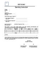
1. Section Names and Function Needle Valve for Test Flame
Arm Lift this arm up when the test cup is set
Adjusts test flame size
Dual Pilot
Heater/Cooler Output Indicator
Lights to ignite test flame when test start
Lights when heater is ON
Thermofuse Detects blaze up of specimen
Display
Fire Containment Lid Reset Knob
Displays test status and result as well as test parameters.
Push this knob to reset the lid to original position
MAIN Switch Used for switching power source to the instrument
Fig. 1 Front-Right View
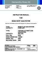
Emergency Switch Activates fire containment lid manually
Arm Handle Handle Hold here when
Fire Containment Lid
Lift/Lower the arm
Activates when tester detects fire
Test Cup Handle Hold here when set/remove the test cup
Flame Size Comparison Bead
Test Flame Nozzle
Adjust test flame size to this bead
Swing over the test
Panel Sheet Switch
USB Port
Operation keys are located
Used for connecting to Keyboard or USB Flash Memory
Fig. 2 Front-Left View 9
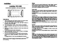
Temperature Sensor Senses specimen temperature
Aco-8as only Skimmer Shaft Skimmer Paddle Removes surface skin Remove this when skimmer is not used
Flash Detector Rings Detects a flash by ionic current
Fig. 3 Around Test Cup
RS-232C Port
Gas Inlet
(25pin)
AC Power Inlet
Fig. 4 Rear View 10
(4) Cleveland Open Cup EXP FP Sample ID
01
Operator
01
Method
ASTM Normal
(1)
OK
23.4 C O O L Gas
A P P L
(5)
oC M E N U
start
reset
2013/12/06(Fri)
Fig. 5 Panel
(2)
(6)
(3)
(1) Color LCD Display: Displays test mode, specimen temperature, flash point (when blinking), expected flash point, trouble message, etc.. (2) START Key: Used when starting test. (3) RESET Key: Used when returning stand-by status. (e.g. stopping a test, stopping a cooling) (4) Left-Right Keys: Used when moving cursor and selecting items. (5) Up-Down Keys: Used when increasing/decreasing numeric figures and selecting items. (6) OK key Used when changed value is settled
11
2. Installation 2.1 Installation Site OVERVOLTAGE CATEGOLY II, POLLUTION DEGREE 2, Altitude up to 2000m
! Warning: The instrument must be installed to the place where there is
ventilation. Flammable harmful vapor and toxic gas are generated by a sample heating, an operator will be in danger of harmful gas poisoning if ventilation is insufficient. When testing a sample which may generate toxic gas, give protection by appropriate PPE(Person Protect Equipment). ! Warning: The instrument must be installed on a flat, sturdy surface to
prevent the instrument from falling over. Do not leave combustible material near the instrument. Place fire extinguisher near the instrument to protect fire disaster. Install the Tester on a draft-free, level and stable table. The Tester needs to be placed at least 20cm away from other objects. Ambient temperature to be 10-30oC and RH to be less than 90% (no condensation) The following locations should be avoided as the installation site: An area exposed to direct the sun An area with poor ventilation An area with dusty air An area higher than 2000m An area subject to rapid changes in ambient temperature
12
2.2 Install Thermal Insulator Install thermal insulator ④ on the brass heating plate ①
so that flame size comparison bead ②
and guide pin ③ passes to 2 small holes (4mmD) of the thermal insulation. There is no front/back side for the thermal insulator.
② ①
④ ③
Fig. 6 Thermal Insulator
2.3 Gas Piping
! Caution:
The gas pressure supplied to the instrument must be lower than 9.8kPa. Ensure that each joint of the gas hose is securely fastened to prevent pulling out of hose by high pressure.
Using the rubber hose supplied for gas, connect the gas source (LP gas or Natural gas) and the gas inlet nipple on the rear panel of the Test Unit. Then fasten both ends with hose bands. See Fig. 4. This tester does not have gas leak sensor. Do not use old/damaged rubber hose which has a risk of gas leak.
13
2.4 Electric Connections
! Warning:
Observe the following instructions when handling AC power cord and electric connections: Do not connect or disconnect AC power cord or electric connections when the mains power is ON. Do not handle any cords or electrical connections with wet hands. Be sure to use the plug to remove cord. Never use the cord to pull a plug from an outlet. Do not place heavy items on cord. Do not use force to bend any cord. Ensure that all electric connections (plugs, sockets, connectors, etc.) are free of dust. Keep cord and electrical connections free of water and other liquids. Failure to adhere to the above precautions may result in electric shock, damage to the instrument, cords, and/or fire due to overheating.
! Warning: Ensure that supply voltage meets the specifications of the
product. Do not turn the power on until all electric connections are secured. Incorrect power supply specifications or loose electric connections may damage the instrument and result in electric shock and/or other electrical accidents. ! Warning: Ensure all ground wires are securely grounded.
Loose or disconnected ground wires may result in electric shock. Never connect ground wires to gas pipes, as this may result in fire or an explosion. Ground wires may be connected to one of the following: Ground terminal of a power outlet Copper bar buried 65 cm or more underground
14
Confirm the voltage of the serial number label located right side of the instrument and your electric source. Plug in the AC power cord to the instrument AC inlet and then other side to an electric outlet(1). Be sure to get grounding to prevent an accident. Note : The power consumption of the aco-8 is 1.0kW . Be careful the total power consumption of the outlet not exceed to the capacity of the outlet
15
3. Daily Check Please check following matters everyday when power ON the instrument Table 1 Checklist Item
Check that…
Appearance
Each part of the instrument is undamaged
Gas Piping
No damage on the gas hose Hose band is securely fastened
Electric Connection
All power cords and cables are free of damage No gap between AC plug and outlet ground wires are securely grounded
Each Function
Stand-by screen displays normally Each key functions correctly Expected Flash Point can be entered correctly Emergency Switch works correctly
! Warning:
If the instrument makes any abnormal noises or exhibits any abnormal behavior, stop operation immediately, turn the power off at the mains, and contact Tanaka Scientific Limited or an authorized distributor.
16
About Fire Containment Lid This unit has a fire containment lid for preventing of expanse of fire when; ① Sample catches a fire, and then thermofuse blows. Error message appears on the display and beeps continuously. Confirm that a fire is extinguished and then push Emergency switch again to alarm clear, push reset to return standby screen. ② Detects fire point Terminate the test, and then flash point and fire point are displayed alternately. ③ Push Emergency Switch The same as ①. Push Emergency switch again to alarm clear, push reset to return standby screen.
T R O U B L E
THERMOFUSE BLOWN 2012/02/27
Fig. 7 Thermofuse
14:58
Fig. 8 Trouble Screen
Fig. 9 Emergency Switch
Fig. 10 Fire Containment Lid
17
Procedure of resetting the fire containment lid is as follows. ① When the fire containment lid activates, display shows error message as shown on left, then buzzer beeps continuously.
T R O U B L
Or display shows flash point and fire point.
THERMOFUSE BLOWN
2012/02/27/
14:58
Fig. 11 Error Message ② Push Emergency switch to clear alarm when display shows “TROUBLE”. Push reset key to return stand-by screen.
②
Fig. 12 Emergency Switch ③ Push the reset knob. Note- Leave test cup on the heating plate.
③
Fig. 13 Reset of Fire Containment Lid 18
4. Test Preparation 4.1 Power ON Turn the MAIN switch ON. Stand-by screen as in Fig. 14 appears on the display.
Cleveland
Open
Cup
Expected Flash Point
EXP FP Sample ID
01
Operator
01
Method
ASTM Normal
Specimen Temperature /Flash Point
Sample ID Test Method
23.4 C O O L
Ignition Source
C
A P P L
Gas
COOL Button
o
M E N U 2013/12/06 (Fri)
Ignition Source Application Button
MENU Button
Fig. 14 Stand-by Screen Expected Flash Point: Enter expected flash point (EXP FP) here before a test start. When MAIN switch is turned ON or reset key is pressed, the display returns to “”. Sample ID: Displays Sample ID. Test Method: Displays Test Method. Specimen Temperature and Flash Point: Displays the temperature measured by Temperature Sensor. Once flash is detected, the flash point blinks/holds this area until reset. Color of the background of the temperature display changes: White : When stand-by Orange : When test is in progress Green : When cooling Ignition Source: Displays “Gas” only. COOL Button: Used when cooling is performed manually. Ignition Source Application Button: Used when ignition source is applied manually. MENU Button: Used when go to MENU screen.
19
4.2 Setting of Expected Flash Point
! Caution:
Ensure that an expected flash point is entered prior to every test run. If an expected flash point is not entered or the value entered is much greater than the actual flash point, the specimen catches a fire at the first application, and then the instrument is destroyed by fire.
The correct expected flash point entering is absolutely imperative. Enter/confirm the expected flash point before each test. The expected flash point (EXP FP) is displayed in three-digit figure in integer. When altering the expected flash point, press the Up-Down key to move the yellow cursor to EXP FP and press OK key. The
numeric figure change from
to 000. After the cursor is moved
to numeric figures of EXP FP, move the digit with Right-Left key and increase/decrease the value with the Up-Down keys. No numeric figures above 400 (760 in oF) can be set. Enter approximate expected flash point even if run a test with SPE method. If expected flash point is unknown, use SPE method and then set higher expected flash point. When selecting SPE method, ignition source application will be done just after start a test. So, a test will be done without worry. The other way, if entered expected flash point is too low, test will be canceled by safety over cut function. (Expected Flash Point+ 30oC(+ 60 oF)).
20
4.3 Entry of Sample ID and Operator Name (NEW) Sample ID can be entered up to 12 letters. The letter which can be entered is following 43 characters in total. Each instrument is initialized to “01” prior to shipping. Table 2 Characters A
B
C
D
E
F
G
H
I
J
K
L
M
N
O
P
Q
R
S
T
U
V
W
X
Y
Z
#
+
-
%
/
0
1
3
4
5
6
7
8
9
(1) Move the yellow cursor to Sample ID / Operator (2) Press OK key, then the yellow cursor moves to entry field of Sample ID/Operator name.
(When Sample ID/Operator Name already registered) (3) Registered Sample ID/Operator name can be selected
Sample
ID
by Up & Down key when Yellow cursor is in large size.
[09]
LUBRICANT Large Cursor
*“01” is registered as default in the list No [01]. (When entering a letter one by one) (4) Press Right-Left Key, then the cursor becomes
Sample
reduced in size (small cursor).
ID
01
+ - [01] nas
Small Cursor
The letter can be changed per single digit. (How to overwrite/register/delete)
Sample
(5) Select the List No of which you want to change the name. Change the letter and press OK to overwrite
ID
TANAKA
Change letters and press OK ↓
Sample
ID
TANAKA
+ - [01] nas
TANAKA
+ - [01] nas
the new name to the List No. (6) Press OK key when the yellow cursor is on plus (+), then the Sample ID/Operator Name is registered to the next List No.
+ - [01] nas
Operator
In this case, “TANAKA”is registered to the List No 02 by pressing OK when the cursor in on “+”.
*Operator can be registered up to 20 names.
List No
*Sample ID can be registered up to 10 names. (7) Press OK key when the yellow cursor is on minus (-), then the registered Sample ID/Operator Name is
Operator
TANAKA
+ - [01] nas
deleted from the list. When optional USB keyboard is installed, sample ID can be entered easily by typing keyboard. For setting of USB port, refer to chapter 8.5 USB Settings.
21
4.4 Selecting of Test Method The aco-8 has more than 10 kinds of test method, Move the cursor with Up-Down key to Test Method and press ok key. After the cursor is moved to the display of the test method, press Up-Down key to select test method. Table 3 Test Method in Celsius Test Method ISO CRM
Contents Used when a sample is CRM. A corrected flash point is rounded to the nearest 0.1 oC. The test proceeds in accordance with ISO 2592 or ASTM
ISO Normal ASTM Normal
D92 until flash point is detected. A corrected flash point is rounded to the nearest 2 oC (ISO) or 1oC (ASTM). Used for measuring the approximate flash point of a
ISO SPE ASTM SPE
sample of unknown expected flash point. Ignition source application is carried out every 2oC from the test start. This is different from the ISO/ASTM Normal method. The test proceeds in accordance with ISO 2592 or ASTM
ISO Fire ASTM Fire
D92 until fire point is detected. A corrected flash point/fire point is rounded to the nearest 2 oC (ISO) or 1oC (ASTM). The test proceeds in accordance with ISO 2592 or ASTM D92 until flash point is detected. The skimmer starts to
ISO Skim* ASTM Skim* *Work on ACO-8as only
work at -30.2oC below EXP.FP, and then work with specified interval to remove surface skin of specimen during a test. A corrected flash point is rounded to the nearest 2 oC (ISO) or 1oC (ASTM). For interval setting, Refer to Chapter 6 Parameter Setting
22
ISO Manual ASTM Manual “For visual detection
The test proceeds in accordance with ISO 2592 or ASTM D92 until flash point is detected by manual detection. A corrected flash point is rounded to the nearest 2 oC (ISO) or 1oC (ASTM).
The test proceeds in accordance with ISO 2592 or ASTM D92 until flash point is detected by manual detection. The ISO Skim+Man* ASTM Skim+Man* *Work on ACO-8as only
skimmer starts to work at -30.2oC below EXP.FP, and then work with specified interval to remove surface skin of specimen during a test. A corrected flash point is rounded to the nearest 2 oC (ISO) or 1oC (ASTM). For interval setting, Refer to Chapter 6 Parameter Setting User can make arbitrary setting for heating rate,
Custom
application interval etc. Refer to chapter 9 User Custom Mode
23
Table 4 Test Method in Fahrenheit Test Method ISO CRM
Contents Used when a sample is CRM. A corrected flash point is rounded to the nearest 2 oF. The test proceeds in accordance with ISO 2592 or ASTM
ISO Normal ASTM Normal
D92 until flash point is detected. A corrected flash point is rounded to the nearest 2 oF (ISO&ASTM). Used for measuring the approximate flash point of a
ISO SPE ASTM SPE
sample of unknown expected flash point. Ignition source application starts at the first (EXP.FP-5x) point after the start. (x=Integer) This is different from the ISO/ASTM Normal method. The test proceeds in accordance with ISO 2592 or ASTM
ISO Fire ASTM Fire
D92 until fire point is detected. A corrected flash point/fire point is rounded to the nearest 2 oF (ISO&ASTM). The test proceeds in accordance with ISO 2592 or ASTM D92 until flash point is detected. The skimmer starts to
ISO Skim* ASTM Skim* *Work on ACO-8as only
work at -30.2oC(-60oF) below EXP.FP, and then work with specified interval to remove surface skin of specimen during a test. A corrected flash point is rounded to the nearest to 2 oF (ISO&ASTM). For interval setting, Refer to Chapter 6 Parameter Setting
ISO Manual ASTM Manual “For visual detection
The test proceeds in accordance with ISO 2592 or ASTM D92 until fire point is detected by manual detection. A corrected flash point/fire point is rounded to the nearest 2 oF (ISO&ASTM).
24
The test proceeds in accordance with ISO 2592 or ASTM D92 until flash point is detected by manual detection. The ISO Skim+Man*
skimmer starts to work at -30.2oC(-60oF) below EXP.FP,
ASTM Skim+Man*
and then work with specified interval to remove surface
*Work on ACO-8as only
skin of specimen during a test. A corrected flash point is rounded to the nearest to 2 oF (ISO&ASTM). For interval setting, Refer to Chapter 6 Parameter Setting User can make arbitrary setting for heating rate,
Custom
application interval etc. Refer to chapter 9 User Custom Mode
In case the temperature at which the first test flame application is made is above the fire point of the specimen, there is a danger: the specimen catches a fire to blaze up. So as to prevent such a danger in advance, for testing a sample of unknown flash point, use the SPE method. Be sure to arrange at least one proper person in your test room, lab, etc., when testing, to cope with possible accidents. ※ Test Sequence of ISO SPE, ASTM SPE in Fahrenheit Entered EXP.FP → 203 oF Start Specimen Temp → 70 oF First Application Temp → 73 oF (Application Interval 5 oF) Over Cut Temp → 263 oF (Entered EXP.FP + 60 oF)
25
4.5 Entering Sample Information Bundle Expected Flash Point, Operator Name and Test Method to Sample No.
MENU
B a c k
S t o r e
(2) Press OK key to display the
I n f o
MENU.
M a i n t e n a n c e U s e r
(3) Move the cursor to Sample Info by
C u s t o m
E q u i p m e n t
Up-Down key.
I n f o
Sample Information Bundle
Up-Down key or Right-Left key at Stand-by screen.
D a t a
S a m p l e
(1) Move the cursor to MENU by
B a c k
(4) Press OK key, the Sample Information will be displayed on
OFF
the screen. (5) Move the cursor to Bundle, and then press OK.
Sample Information Bundle Set Sample No.
B a c k
(6) If you select ON by UP-Down key, the left display will appear and
ON
then you can resister Expected
[01]
Flash Point, Sample ID, Operator
Exp. FP
000
Name and Test Method.
Sample ID
TEST-SAMPLE
Refer to 4.2~4.4 for the entry.
Operator
TANAKA
Method
ASTM Nomal
*Sample No. can be registered up to 20.
26
4.6 Preparation of Test Cup and sample (1)
Wash the test cup with the cleaning solvent to remove any test specimen or traces of gum or residue remaining from a previous test. When the upper side of cup’s flange is covered with carbon deposit, the flash detector cannot operate normally. Also when conductive material adheres to the insulator of electrode ring (outer ring), bad insulation can cause mis-detection of flash. Therefore, keep the parts cleanly.
(2) When testing samples of very viscous materials and containing dissolved or free water, follow Sampling section of ISO 2592/ASTM D92. (3) Fill the test cup with the test specimen to the filling mark inside of the test cup. (4) Push up the arm handle and place the test cup on the center of the heater. (5) Lower the arm gently until stopper is touching the flange of the cup.
Fig. 15 Test Cup Handle Position (Left: Correct, Right: Wrong)
Now you have completed the preparation for the test.
27
5. Test Sequence 5.1 Test Start
! Warning:
Never touch around test cup during testing. An operator gets burned.
! Warning:
Never run the tester unattended. The specimen may catch a fire and blaze up by some sort of cause. It is essential that at least one-trained personnel be present in the test room.
! Warning:
If the instrument makes any abnormal noises or exhibits any abnormal behavior, stop operation immediately, turn the power off at the mains, and contact Tanaka Scientific Limited or an authorized distributor.
Open the main gas cock, and then press the start key to start a test. The background of the temperature display turns orange as the Run condition. See Fig. 16. (If press the start key without entering expected flash point, display shows “INVALID EFP”. Press reset key to return Stand-By Screen) The expected flash point(4) is displayed for 5 seconds on the temperature display. The dual pilot turns on, specimen heating starts(5) .
Cleveland Open Cup EXP FP Sample ID
01
Operator
01
Method
ASTM Normal
23.4 C O O L
A P P L
Gas
oC
M E N U 2013/12/06 (Frin)
Fig. 16 Run Screen
28
Note(4): Expected Flash Point can be changed even during the test. After changing expected flash point in accordance with Section 4.2, re-press the start key. Also in this case, the newly set expected flash point appears in the center of the display for 5 seconds. Note(5) Heater output can be confirmed by Heater Output Indicator. Lighting: 100% full power Extinction: 0% (no heat) Blink: interlevel In most cases, heater output varies and then this indicator blinks. Test flame is ignited by dual pilots automatically. The time until auto ignition will be seconds (continuous run) to minutes (first run)(6). Do not leave the instrument until ignition is confirmed. Adjust the test flame to 4mm in diameter (the flame size comparison bead size) by needle valve. Note(6): The first run after the gas piping (installation or transfer of the instrument), there is full of air in the gas hose. Lift the windscreen and then open the needle valve for test flame fully to get out air from the hose. Be careful that the big flame comes out from the nozzle when ignites. After this, turn the needle valve clockwise to adjust the flame size. Besides, flame grows big slowly because the portion of the gas increases with the same flow rate till air can be removed completely. Please take care valve operation diligently for the first run. The test proceeds automatically hereafter.
29
5.2 Test Sequence After the test starts, the specimen temperature rises at a rate of 14 to 17 oC /min(25 to 30 oF /min). When the temperature reaches 56 oC (100 oF) below the expected flash point, the heating rate is decreased so that the rate of temperature increase during the last 28 oC (50 oF) before the expected flash point is 5 to 6 oC(9 to 11 oF). When the temperature of the test specimen is 28 oC(50 oF) below the expected flash point, the test flame begins to apply. After that, the application operation is repeated at each 2 oC(5 oF). Note: heating rate might be unstable in particular kind of sample like asphalt.
5.3 Flash Detection When a flash is detected, the Flash Point is displayed on the screen as Fig. 17, and then starts blink(7). At the same time buzzer beeps intermittently for 8 seconds. Furthermore, the solenoid valve for gas is closed, the test flame goes out and dual pilot goes off, and the stove section starts cooling. (background of temperature display turns green). When “ASTM Fire” or “ISO Fire” Method is selected, aco-8 suspends a test 1 minute. During this suspend, push start key again to continue fire point test, otherwise aco-8 terminates a test and then starts cooling. Please do not leave the aco-8 until fire point is detected. Fire point test is dangerous. Cleveland Open Cup EXP FP Sample ID
01
Operator
01
Method
ASTM Normal
Corrected Flash Point
224.0 C o
C O O L
A P P L
Gas
M E N U 2013/12/06 (Fri)
Fig. 17 Flashed in Good Condition Note(7): The blinking flash point on the screen is held until reset key or start key is pressed. Once reset key or start key is pressed, temperature display returns to present specimen temperature.
30
The Flash Point (8) blinking on the screen is corrected by barometric pressure and rounded, not observed. The test result is automatically stored in the memory. To view the stored data, refer to chapter 0. Data Storage. Note(7)(8):The calculation of the flash point is done by following procedure. (1) Calculate the corrected flash point, Tc, using the following equation TC = To + 0.025(1013 - P) where To: the observed flash point, in oC P :the barometric pressure (hPa) measured by built-in barometric pressure sensor (2) Round Tc to the nearest 1.0 oC(ASTM) or 2.0 oC (ISO) or 0.1 oC(ISO CRM)
(2.0 oF)
(2.0 oF)
(2.0 oF)
For example, the flash is detected at 222 oC. And then measured barometric pressure is 970hPa, the corrected flash point will be “223.075” by above equation, then to be “223” by rounded to the nearest 1.0 oC(ASTM), then to be “224” by rounded to the nearest 2.0 oC(ISO). When measured barometric pressure is between 974 and 1052hPa, observed flash point and the flash point will be the same value.
31
< When a flash is detected at first application of the ignition source > When a flash is detected at the first ignition source application, the test is terminated. In this case, screen shows “INVALID: flashed on 1st appl” under the flash point display as Fig. 18. Do a test again with fresh sample and lower EXP FP. If flash is not observed, the test is continued as follows. Cleveland Open Cup EXP FP Sample ID
01
Operator
01
Method
ASTM Normal
Corrected Flash Point
194.0 C O O :Lflashed on A 1P stP appl L INVALID Gas
oC
M E N U 2013/12/06 (Fri)
Fig. 18 Flashed on 1st application
32
< When a flash is detected at out of limit > When a flash point is detected at a temperature which is less than 18 oC (32 oF) above the temperature of the first application of the ignition source, INVALID and its detail appear under the flash point. See Fig. 19.
Cleveland Open Cup EXP FP Sample ID
01
Operator
01
Method
ASTM Normal
Corrected Flash Point
210.0 C o
o INVALID C O O: Lflashed @ A< P18 P LC aft 1stM appl E N U
Gas
2013/12/06 (Fri)
Fig. 19 Flash is detected out of limit
33
< If a flash has not been detected when the safety cut temperature is reached > This instrument has a function to prevent overheat called “safety cut temperature”. The safety cut temperature is set at EXP FP+30 oC (+60 oF)or upper limit of the test method. If a flash has not been detected when the safety cut temperature is reached, terminate the test forcibly. (Solenoid valve for gas is closed, the test flame goes out and dual pilot goes off, and the heater
section starts cooling down) The buzzer beeps intermittently for 8 seconds again.
The following screen is an example of the safety cut temperature termination.
T R O U B L E
Flash Point > 252 oC 2012/02/27 14:35
Fig. 20 Safety Overcut Screen
5.4 Fire Point Detection When “ASTM Fire” or “ISO Fire” Method is selected, and then operator push start key again after detectiong flash point, aco-8 continue a test until fire point. ※Please note that there is no automatic transition from the flash point test to the fire point test. Once flash point is detected the buzzer sounds intermittently for 1 min, please push start key again within 1 min to continue a fire point test. When aco-8 detects continuous specimen burning for 5 seconds, test is terminated, fire containment lid activates to extinguish a fire, and then display shows fire point and flash point alternately. In the fire method, aco-8 does not move to cooling cycle automatically for safety reason. Operator has to confirm the fire is extinguished completely, and then reset fire containment lid to the original position, then move the cursor to COOL by Up-Down key or Right-Left key, and then press the OK key to start cooling.
34
5.5 Flash Point Detection By manual detection First of all the flash point detection principle of aco-8 is considered as a flash when there is conduction between two large and small flash detection rings (usually insulated). This means that if there is conduction between the rings other than the flame at the time of flash point, it will be detected. Therefore, If the sample expands excessively due to heating and touches the rings, or if bubble is generated from the sample and touches the rings, false detection may occur. In such cases, please use the following manual detection mode. When “ASTM Manual” or “ISO Manual” or “ASTM Skim+Man” or “ISO Skim+Man” Method is selected, aco-8 ignores the first detection even if detected by foam or sample expansion, and then operator push start key again after ignoring the first detection, aco-8 continue a test until flash point detection.However, even if the initial sample expansion or bubble contact to rings can be detected automatically, there is no way to determine which is the true flash point, so the flash point detection is a visual check by operatiors. Once the first detection by sample expansion or bubble is detected the buzzer sounds intermittently for 1 min, please push start key again within 1 min to continue a test. After that, automatic detection is not possible, so flash point detection is a manual operation by visual check. Do not leave until you see the flash point or test end. After visually checking the flash point please press the START key immediately. Pressing the START key is regarded as a flash point detection and the flash point result is displayed. In these method, aco-8 does not move to cooling cycle automatically for safety reason. Operators move the cursor to COOL by Up-Down key or Right-Left key, and then press the OK key to start cooling.
35
5.6 Test End
! Warning:
Never touch the test cup with bare hands after the test end. The sample cup may still hot and the operator gets burned. Use gloves and hold the test cup handle for operator’s safety.
! Warning: Never discard hot sample to a waste tank. Sample in the
waste tank may blow up. ! Warning:
Never discard hot sample to a waste tank. Sample in the waste tank may blow up.
The cooling stop automatically (the green background on the temperature display turns white) in 10 minutes (9). When further cooling is required, move the cursor to COOL by Up-Down key or RightLeft key, and then press the OK key. Cooling is available for another 10 minutes (9). Cooling cycle can be canceled by pressing the reset key. The temperature display (flash point) is held until the reset key is pressed. Note(9): Cooling time is adjustable. For changing cooling time, refer to chapter 6. Test Parameter Setting. One cycle of a test is completed at this moment and you can start the next test. Press reset key first, and then return to section 4.2 Setting of Expected Flash Point when the next test is available. If not press reset key, and then press start key, display shows INVALID EFP. Turn the MAIN switch of the instrument off and close the main gas cock when today’s work is finished.
36
6. Test Parameter Setting When test parameter needs to be changed from factory setting, please change them by following procedure. (1) To change test parameters, move
MENU
the cursor to MENU (turns yellow) in
B a c k
the stand-by screen by Up-Down
S t o r e
key, and then press the OK key.
D a t a (2)
M a i n t e n a n c e U s e r
cursor to Maintenance by Up-Down
C u s t o m
E q u i p m e n t
After change the screen, move the key, and then press the OK key.
I n f o
Fig. 21 MENU Screen (3) Press OK when the cursor is on
Maintenance
B a c k
calibration.
C a l i b r a t i o n D a t e & T i m e R S - 2 3 2 C U S B
S e t t i n g
s e t t i n g s
s e t t i n g s
P a s s w o r d
s e t t i n g s
(4) Press OK when the cursor is on Test
Calibration
B a c k
T e s t
P a r a m e t e r
T e m p
c o r r e c t i o n
B a r o
c o r r e c t i o n
S a m p l e B a t h P r i n t
Parameter.
0 – S p a n
0 – S p a n C a l
T i c k e t
37
Test Parameter
(5) After the cursor is moved to the
B a c k
numeric figures of each item, move the digit with Right-Left key and increase/decrease the value with the
T e m p
u n i t
o
I n i t 保存データ
h e a t
3デー 0 %
C o o l
t i m e
1 0 m i n
A p p l
t e m p
2 8 oC
D e t
s e n s
S k i m
C
Up-Down keys. (6) Press the OK key to fix the value. (7) Move the cursor to Back, and then press OK to MENU screen, or Press
S t d
reset key to return stand-by screen.
0 2 oC
i n t v l
Fig. 22 Test Parameter Screen Temperature Unit Setting: Select temperature unit oC or oF. Default setting is oC Initial Heat Setting: Too strong an initial heat would cause hunching of temperature rise rate. Too weak an initial heat could not reach the set rate. Please input an even number (every 2%) Standard value of Initial Heat is as follows.
AC Source Standard Value
100V
110V
115V
120V
220V
230V
240V
30
28
26
24
26
24
22
Cooling Time Setting: Cooling time can be change from 00min (No Cooling) to 99min. Test Flame Application Start Temperature Setting: This value means flame application starts from XXoC below EXP.FP. Default value is 28. Detection Sensitivity Setting: If the sensitivity is so high as to detect a flame that could not reach a flash point, select Low. Hight is solely for silicon oil and must not be selected for others. When testing silicone oil, set the flash detecting sensitivity to High and use flash detector ring dedicated for silicone (option). Default setting is “Std”. Skimmer Interval Setting (apply only aco-8as): Select skimmer interval time. Input even number like 2, 4, 6…. Default setting is2 oC(4 oF) .
38
7. Data Storage aco-8 has a data storage function. Up to 200 test data can be memorized. After aco-8 detects a flash point, the data will be stored automatically. The recalling procedure is as follows.
MENU
B a c k
(1) Move the cursor to MENU by UpDown key or Right-Left key.
S t o r e
(2) Press OK key to display the
D a t a
MENU.
M a i n t e n a n c e U s e r
(3) Move the cursor to Store data by
C u s t o m
E q u i p m e n t
Up-Down key.
I n f o
Fig. 23 MENU Screen
Storedata
(4) Press OK key, the stored data will
B a c k
be displayed on the screen as Fig. No
Sample ID:
000 001 002 003 004 005 006 007 008 009
LUBE0287 LUbE0286 FPRM4D FPRM2D FPRM14 LUBE0285 AAAAAAAAAAAA AAAAAAAAAAAA
Date & Time 12/02/27 12/02/27 12/02/27 12/02/27 12/02/27 12/02/27 12/02/20 12/02/20
15:30 14:21 13:27 12:30 11:26 10:48 09:34 09:00
Result 266.0oC 258.0 oC 223.5 oC 163.2 oC 116.1 oC 165.5 oC 166.0 oC TRBL
24 Stored Data Screen. (5) Press Down key to display next 10 data, press UP key to display previous 10 data. (6) Move the cursor to Back, and then press OK to MENU screen, or Press reset key to return stand-by screen.
▽
Fig. 24 Stored Data Screen To re-print certain data, the procedure is as follows. (Software version “8FP20” or later) (1) Connect dedicated printer. (2) Press Right-Left key at Stored Data Screen to turn the cursor yellow in No area. (3) Select the data by pressing Up-Down key. (4) Press OK to start re-print. 39
8. Maintenance Indicated temperature correction, date and time setting, barometric pressure sensor calibration, RS232C settings, USB settings and password setting are done by pressing panel keys. The operation procedure is as follows.
MENU
B a c k
(1) Move the cursor to MENU by UpDown key or Right-Left key.
S t o r e
(2) Press OK key to display the
D a t a
MENU.
M a i n t e n a n c e U s e r
(3) Move the cursor to Maintenance
C u s t o m
E q u i p m e n t
by Up-Down key, then press OK
I n f o
key.
Fig. 25 Menu Screen (4) After change the screen, select
Maintenance
the item by Up-Down key, and
B a c k
then press OK key.
C a l i b r a t i o n D a t e & T i m e S e t t i n g R S - 2 3 2 C U S B
s e t t i n g s
s e t t i n g s
P a s s w o r d
s e t t i n g s Calibration
Fig. 26 Maintenance Screen
B a c k
T e s t
P a r a m e t e r
T e m p
c o r r e c t i o n
B a r o
c o r r e c t i o n
S a m p l e B a t h P r i n t
40
0 – S p a n
0 – S p a n C a l
T i c k e t
8.1 Temperature Correction Displayed temperature can be adjusted by inputting temperature offset values. For the detail and procedure of temperature calibration, refer to aco-8 Maintenance Manual. (1) Move the cursor to temperature
Temp Correction
correction point by Up-Down key
B a c k
or Right-Left key. (2) Press OK key to move the cursor to offset value.
POS
+0.0
0
+0.0
40
+0.0
80 保
+0.0 保
120 保
+0.0 保
160 保
+0.0 保
(3) Change offset value by Up-Down
200
+0.0
240
+0.0
280
+0.0
key, and then press OK key.
320
+0.0
360
+0.0
400
+0.0
(4) After complete the changing, move the cursor to Back by UpDown key, then press OK key to return the Maintenance Screen, or press reset key to return the
Fig. 27 Temperature Correction Screen
Stand-by Screen.
8.2 Date and Time Setting Displayed date and time can be adjusted by following procedure (1) Move the cursor to date and time
Date & Time Setting
B a c k
column by Up-Down key, and then press OK key. (2) After the cursor is moved to numeric figure, move the cursor
2 0 1 2
0 2
2 7
1 5 : 5 3
by Right-Left key and then change the value by Up-Down key. (3) After inputting present date & time, press OK key to set the clock. (4) After complete the setting, move the cursor to Back by Up-Down
Fig. 28 Date and Time Setting Screen
key, then press OK key to return the Maintenance Screen, or press reset key to return the Stand-by Screen
41
8.3 Barometric Pressure Correction Barometric pressure sensor correction, pressure unit changing and valid/invalid of barometric pressure correction can be done by following procedure.
Barometric Pressure
(1) Move the cursor to the item by
B a c k
Up-Down key, and then press OK key.(
P r e s e n t
1 0 0 1
B a r o S e t 保存データ
1保存 0 0 1
B i a s
S e t
U n i t B a r o
(2) After the cursor is moved to the right column, change the value by
- 0 0 1 7 h P a
C o r r
Up-Down key, and then press OK key. (3) After complete the changing,
O N
move the cursor to Back by UpDown key, then press OK key to return the Maintenance Screen,
Fig. 29 Barometric Pressure Setting Screen
or press reset key to return the Stand-by Screen.
8.4 RS-232C Settings When connecting aco-8 to optional printer or PC, data transfer format may be changed. The changing procedure is as follows. Below setting is for connecting optional printer, BS-80TS.
RS-232C Settings
(1) Move the cursor to the item by
B a c k
Up-Down key, and then press OK key. (2) After the cursor is moved to the
F o r m a t
P r i n t e
right column, change the value by
B a u d 保存データ
R a t e
9保存 6 0 0 b p
Up-Down key, and then press
D a t a
B i t s
7 b i t s
OK key.
P a r i t y
O d d
S t o p
B i t s
2 B i t s
move the cursor to Back by Up-
L i n e
F e e d
C R L F
Down key, then press OK key to
(3) After complete the changing,
return the Maintenance Screen, or press reset key to return the
Fig. 30 RS-232C Setting Screen
Stand-by Screen. Format: Select Comm when PC (LIMS) is connected. 42
Comm 1 : Current communication format *P.39 Comm 2 : Additional communication format ( Not transferred when trouble) *P.40
8.4.1 Connection The connection to a computer is through the 25 pin or 9 pin D-Sub type connector located at the back of the control unit. An extreme care should be taken when making pin-to-pin connections, since the tester is a DTE device.
8.4.2 Pin Assignment The pin assignment is as follows: Table 5 Pin Assignment Pin #
Signal
Function
Direction
1
GND (FG)
Frame Ground
2
TXD (SD)
Transmitting Data
Tester Computer
3
RXD (RD)
Receiving Data
Computer Tester
4
RTS (RS)
(Connect w/pin #5)
5
CTS (CS)
(Connect w/pin #4)
6
DSR (DR)
(See note-1)
7
GND (SG)
Signal Ground
20
DTR (ER)
(See note-2)
Computer Tester Tester Computer
Note: When starting data communication, switch this signal line to “0” logic (3V to 12V). This signal line turns to “0” when the tester detects a flash; then turns “1” (-12V) when press RESET key. This signal is provided for user’s convenience.
8.4.3 Signal Voltages Input Voltages “0”: Output Voltages
3V to 12V “1”:
-3V to –12V
“0”:
12V
“1”:
-12V
43
8.4.4 Example for Connection As an example for the connection, connection with IBM/AT compatible is as illustrated below.
Tester(25P)
Computer(25P)
FG
1
1
FG
TXD
2
2
TXD
RXD
3
3
RXD
RTS
4
4
RTS
CTS DSR
5
5
6
6
CTS DSR
SG
7
7
SG
DTR 20
20 DTR
Tester(25P)
Computer(9P)
TXD
2
2
RXD
RXD
3
3
TXD
RTS
4
4
DTR
CTS DSR
5
5
6
6
GND DSR
SG
7
7
RTS
DTR 20
8
CTS
44
8.4.5 Transmitted Data The data consists of ASCII coded 39 characters. It starts with “STX” and ends with “ETX”.
(Comm 1) STX
A
C
O
8
0
2
CR
0
LF
0
Instrument No. (6 ltrs)
1
3
8
.
0
CR
1
4
.
0
0
0
1
CR
LF
Test No. (6 ltrs)
LF
1
Flash Point (5 ltrs)
0
0
4
0
.
0
CR
LF
EXP FP (5 ltrs) CR
LF
ETX
No. of Applications ( 5 ltrs)
Instrument No.:
The first 4 characters represent the model; last 2 the ID number.
Test No.:
A six-digit number that is increased one by one as a test is executed properly.
Flash Point:
The number is a 4-digit number including 1 digit after decimal point. In case of the following situation, this number is replaced by character strings:
Trouble during test. “TRBL_” (4 letters plus 1 space) The flash point is detected during the first application. “UNDER” (5 letters) The actual flash point exceeded the safety cut temperature. “OVER_” (4 letters plus 1 space) No. of applications:
The number of ignition source applications when the flash point is detected. (If the flash point is detected at the 10th application, the value is “010.0”.)
45
(Comm 2) NEW
46
8.5 USB Settings When connecting a key board to aco-8, select a type of keyboard (layout, LED, ten key) by following procedure. (1) Move the cursor to the item by Up-Down key, and then press
USB Settings
B a c k
OK key. (2) After the cursor is moved to the right column, change the value by
Keyboard layout LED on keyboard 保存デー Ten key keypad
United States
Up-Down key, and then press
Without LED 保存デ
OK key.
Without ten key
Store parameters Load parameters
(3) After complete the changing, move the cursor to Back by UpDown key, then press OK key to
Cancel
return the Maintenance Screen,
Store results
or press reset key to return the Stand-by Screen.
Fig. 31 USB Setting Screen Current parameters and test data in aco-8 can be copied to an USB memory with csv format, and aco-8 can load saved parameters from the USB memory. The procedure is as follows.
Store Parameters: Plug in an USB memory Move the cursor to Store parameters Press OK. After store parameters, confirm that the csv file is created in the USB memory by a PC.
Load Parameters: Plug in an USB memory Move the cursor to Load parameters Press OK Select/Confirm file name Press OK.
Store Result: Plug in an USB memory Move the cursor to Store results Press OK.
47
8.6 Password Settings Caution!:
Once password is set, and then forgot the password, the unit cannot recovered. Please record the password to the safe place.
aco-8 has a function to protect parameters by user own password. The procedure for setting a password is as follows.
8.6.1 Setting Password (1) Move the cursor to Password by
Password Settings
B a c k
Up-Down key, and then press OK key. (2) Select “Use” by Up-Down key,
Password
Not use
Old password 保存
************ 保存データ
New Password
************
then press OK key. (3) Move the cursor to New Password by Up-Down key, and then press OK key. After the cursor is moved to the right column, enter password (max. 12 characters) by Up-Down key and Right-Left key, and then press
Fig. 32 Password Setting Screen
(4)
OK key.
“Password has been changed.” appears on the screen. (Use of external key board is easy)
(5) After complete the changing, move the cursor to Back by Up-Down key, then press OK key to return the Maintenance Screen, or press reset key to return the Stand-by Screen.
After setting password, following screen appears when go to Maintenance screen. Enter password by Up-Down key and
Enter Password
Right-Left key, and then press OK key. Maintenance screen appears by
this operation.
Enter password and push OK key.
Fig. 33 Password Entering Screen
48
8.6.2 Changing Password (1) Go to Password Setting Screen. (2) Move the cursor to Old Password by Up-Down key, and then press OK key. (3) After the cursor is moved to the right column, enter old password by Up-Down key and RightLeft key, and then press OK key. “Password matched.” appears on the screen. (4) Move the cursor to New Password by Up-Down key, and then press OK key. (5) After the cursor is moved to the right column, enter new password by Up-Down key and RightLeft key, and then press OK key. “Password has been changed.” appears on the screen. (6) After complete the changing, move the cursor to Back by Up-Down key, then press OK key to return the Maintenance Screen, or press reset key to return the Stand-by Screen.
8.6.3 Clear Password (1) Go to Password Setting Screen. (2) Move the cursor to Password by Up-Down key, and then press OK key. (3) Select “Not use” by Up-Down key, then press OK key. (4) Move the cursor to Old Password by Up-Down key, and then press OK key. (5) After the cursor is moved to the right column, enter old password by Up-Down key and RightLeft key, and then press OK key. “Password matched.” appears on the screen. (6) Move the cursor to Back by Up-Down key, then press OK key to return the Maintenance Screen, or press reset key to return the Stand-by Screen.
8.7 Calibration Ticket (NEW)
Calibration
Calibration Ticket
B a c k
T e s t
P a r a m e t e r
T e m p
c o r r e c t i o n
B a r o
c o r r e c t i o n
S a m p l e B a t h P r i n t
0 – S p a n
0 – S p a n C a l
T i c k e t
(1) Calibration Ticket is printed out by pressing OK when the cursor is on “Print Cal Ticket” For Sample 0-span and Bath 0-Span, please consult with Tanaka Scientific Limited 49
9. User Custom Method The procedure of User Custom method setting is as follows. (1) Move the cursor to Temp Rate by
User Custom
B a c k
Up-Down key, and then press OK key.
T e m p F l a m e
R a t e (2) After change the screen, Move
A p p l i c a t i o n
the cursor to the item by UpDown key, and then press OK
Temp Rate
B a c k
key. (3) After the cursor is moved to the
Temp Rate 1
3 . 0
Temp Rate 2 保存データ
保存3 . 0
Change temp
0 1 0
right column, change the value by Up-Down key, and then press OK key. (4) move the cursor to Back by UpDown key, then press OK key to return the User Custom
Flame Application
Interval 1 Interval 2 保存データ
Screen, or press reset key to
B a c k
return the Stand-by Screen.
10 . 0 保存2 . 0
Start Temp
1 0 0
Change Temp
0 8 0
Fig. 34 User Custom Method setting Screen Temp Rate 1: Apply from test start to EXP FP- Change temp. Select from 3.0, 5.5, 10.0 and 15.5 Temp Rate 2: Apply from EXP FP- Change temp to test end. Select from 3.0, 5.5, 10.0 and 15.5 Change temp: Heating rate switching temperature. Enter XXXoC below EXP FP. Interval 1: Apply from test start to EXP FP- Change temp. Select from 0.5, 1.0, 2.0, 5.0, and 10.0. Interval 2: Apply from EXP FP- Change temp to test end. Select from 0.5, 1.0, 2.0, and 10.0 Start Temp: Test Flame application starting temperature. Enter XXXoC below EXP FP. Change Temp: Test Flame application switching temperature. Enter XXXoC below EXP FP. 50
10. Equipment Information Equipment information can be seen by Equipment Information screen. Only ID Number can be changed by user. If several aco-8 is used, set ID number 01, 02, 03…. so that Lims system can identify the unit. (1) Move the cursor to ID Number by
Equioment Info
Up-Down key, and then press
B a c k
OK key. (2) After the cursor is moved to the
S e r i a l N o : 3 1 0 0 1
right column, change the value by
S o f t w a r e : 8 F P 3 1
Up-Down key, and then press
M a i n
OK key.
I D
P C B : 1 3 – 1 0
N u m b e r
(3) Move the cursor to Back by Up-
0 0
Down key, then press OK key to return the Maintenance Screen, or press reset key to return the Stand-by Screen. Fig. 35 Equipment Information Screen
51
11. In Case of Abnormal Operation or Trouble ! Warning: Do not attempt to repair the instrument yourself. In the event
that the instrument exhibits any abnormal behavior whatsoever, contact Tanaka Scientific Limited or an authorized distributor. ! Warning: Only Tanaka Scientific Limited service personnel or
authorized representatives are to repair or maintain the instrument. Self Diagnose Function When a problem occurs on the Tester, a buzzer will sound and one of the trouble messages in Table 6 will be shown. When one of these events occurs, all outputs will be shut off. For troubleshooting, refer to the Maintenance Manual or consult Tanaka authorized distributor.
52
Table 6 Trouble Messages Trouble Control computer runs way
Temperature sensor for sample is found defective Flash detector is found defective
Message on Display
Buzzer Beeps continuously
None
TROUBLE
Beeps intermittently for eight (8) seconds
SAMPLE TEMP SENSOR TROUBLE
Beeps intermittently for eight (8) seconds
FLASH DETECTOR Electric ignitor is found defective
TROUBLE
Beeps intermittently for eight (8) seconds
FILAMENT BREAK Built-in battery has expired
TROUBLE
Beeps intermittently for eight (8) seconds
REPLACE BATTERY Arm is not set in place
TROUBLE
Beeps intermittently for eight (8) seconds
ARM POSITION Thermofuse is blown
TROUBLE
Beeps big sound continuously
THERMOFUSE BLOWN Application motor is found defective
TROUBLE
Beeps intermittently for eight (8) seconds
APPL MOTOR
Abnormal behavior without trouble message If the instrument exhibits any abnormal behavior without any trouble message, refer to the aco-8 Maintenance Manual or consult Tanaka authorized distributor.
53
12. Periodic Inspection, Adjustment and After Sales Service 12.1 Periodic Inspection In order to maintain accurate performance of the aco-8 and to guarantee safe operation of the instrument, periodic inspections must be performed at regular intervals. For detail, refer to the aco-8 Maintenance Manual. Gas piping inside the instrument is made of Nylon tube; outside, Viton tube. Gas is very dangerous if it leaks. Consult the Tanaka authorized distributor for periodical gas leakage check. THE TESTER IS NOT EQUIPPED WITH A GAS LEAKAGE DETECTOR.
12.2 Adjustment The aco-8 is already adjusted for common users, but further adjustment may be require for accuracy control or customizing some parameters, like creating user custom mode, changing cooling time, connect to a printer or PC. For detail, refer to the aco-8 Maintenance Manual.
13. After-sales Service ! Caution: Use only Tanaka Scientific Limited genuine consumables,
parts and accessories or such parts as recommended by Tanaka Scientific Limited. For ordering consumable items or parts or to request servicing, please contact Tanaka authorized distributor. Please note that spare parts that are necessary to maintain/regain the function of this instrument is kept in inventory for a minimum of 5 years after the delivery of this instrument. The main consumables are listed to Table 7 Main Consumables. Please use the code# and part name with the model name “aco-8” when you place an order.
Code#
Table 7 Main Consumables Part Name
1000949
TEST CUP ASSEMBLY
1000711
THERMOFUSE, Pack of 5, with Insulation Tube.
1001020
IGNITER TOP for aco-8
1001018
TEMPERATURE SENSOR for aco-8
1005152 1000267
HEATER COIL, 100/120V 800W, for 100/120V model HEATER COIL, 220/240V 800W, for 220/240V model
1000960
INNER DETECTOR RING
1000961
OUTER DETECTOR RING
1000964
INSULATING COLLAR for aco-8
1001027
SKIMMER PADDLE (for aco-8as only) 54
14. Other Cautions 14.1 Caution when this instrument is not used for a long time When this instrument is not used for a long time, please pull AC power cord out of an outlet. In addition, please put cover not to be affected by dust and moisture.
14.2 Precaution in case of Loss of Instruction Manual The Instruction Manual is a part of this instrument. In case it is lost, please request a new copy to Tanaka authorized distributor. Also, it is highly recommended that the address and telephone number of Tanaka and/or its authorized distributor be kept separately from this Manual.
14.3 Caution when Transferring This Instrument When this instrument is transferred or sold to a third party, please inform Tanaka or its authorized distributor. Wrong source voltage and/or AC frequency could cause damages or malfunctioning. In case of transferring this instrument, make sure to attach this Instruction Manual.
14.4 Caution when Discarding This Instrument This instrument does not include harmful substance; please discard this instrument according to the local regulations.
55
15. Specification Conforming standard:
ISO 2592, ASTM D92, IP34
Measuring Range:
Ambient to 400 oC(700 oF)
Test Modes:
ISO CRM, ISO Normal, ISO SPE, ISO Flash & Fire, ISO Skim*, ASTM Normal ASTM SPE, ASTM Flash & Fire, ASTM Skim*, and User Custom *:aco-8as only
Display:
5.7 inch (117 x 88mm) color LCD with LED back light
Temperature Sensor:
PT-100 in stainless steel sheath
Flash Detector:
Double Ionization Rings
Heater:
Nichrome Coil heater 800@115V or 800W@230V
Cooling Device:
Forced air cooling by sirocco fan
Ignition Source:
Gas ignition with automatic lighting
Barometric Correction:
By built-in barometric pressure sensor
Safety shutdown:
Automatically shuts off and the problem is reported by buzzer and display in case: (a) EFP+30 oC (+60 oF) or 400 o C(700 oF) is reached, (b) Temperature sensor for sample is found defective (c) Flash detector is found defective (d) Thermofuse is blown (also fire containment lid activates) (e) built-in battery is found drained out (f) arm is not set in place (g)control computer runs away (no display)
Dimensions & Weight:
230W x 470D x 390H(mm), approx.16kg
Operation room temp.:
10 to 35 oC (50-95 oF)
Humidity:
less than 90% (No Condensation)
Altitude:
less than 2000m
Overvoltage Category:
II
Pollution Degree:
2
Utility: Power Supply:
100/120VAC or 220/240VAC, 50/60Hz (set at the factory), 1000W Max.
Gas Supply :
LP gas or natural gas (Max. pressureAC200V) or 3.0m (