![Air Compressor Maintenance Log PDF [PDF]](https://pdfs.asia/img/200x200/air-compressor-maintenance-log-pdf.jpg)
5 0 31 KB
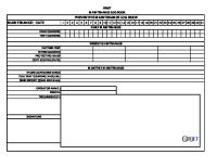
Air Compressor Maintenance Log Make:
Model:
Serial No.:
To use this maintenance log, check and sign in the appropriate boxes as routine maintenance is performed. Record any notes or information that could be used for future reference in the Maintenance Notes box.
Oil Filter Date
Hours
Air Filter
Air/Oil Sep.
Lubricant
Oil Temp. Part No.
Part No.
Part No.
Maintenance Notes
Initials
Part No.
Download and print a new free maintenance log at www.IndustrialAirPower.com [email protected]
toll free 877-422-1717
www.IndustrialAirPower.com
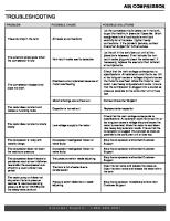
For maximum maintenance bene�t, use the Suggested Maintenance schedule below or consult your operator’s manual to set a regular maintenance schedule.
SYMPTOM
CAUSE • Incompatible oil in compressor.
If you have any questions, please contact us at 877-422-1717 or www.IndustrialAirPower.com.
SUGGESTED MAINTENANCE Every 1,500 - 2,000 hours Every 2,000 hours Up to every 4,000 hours (depending on air quality) Yearly OR when pressure differential reaches 10 psi
SYMPTOM
High discharge temperature
Change air/oil seperator
• Clogged or varnished heat
• Insufficient air circulation at oil cooler.
• Excessive air demand. Decreased discharge pressure
CORRECTION
• Inspect lubricant lines for blocks. • Analyze lubricant. • If varnish is present, �ush with cleaner.
• Restriction of heat exchanger
sticking.
• Ruptured intake air path/�lter.
Change air �lter
• Fill lubricant.
• Faulty thermal by-pass valve.
• Minimum pressure valve
• Review and analyze oil. • Replace with proper lubricant. • Rebuild or replace valve. • Inspect inlet �lter and air path, checking for voids. Replace and repair as needed.
Analyze lubricant
• Sump lubricant low.
air �ow.
Failure to start
• Check plant air demand and inspect plant for air leaks.
• Service valve open.
• Close valve.
• Leaky service line.
• Fix leaks.
• Plugged inlet air �lter.
• Clean or replace �lter.
• Inlet valve partially closed.
• Check inlet valve assembly and rebuild as needed.
• Safety shut-down tripped.
• Re-set compressor safety.
• Disconnected main switch.
• Check switch and verify that power is ON.
• Power failure.
• Check power supply.
• Plugged air/oil separator.
• Change separator element.
• Wrong air pressure setting.
• Adjust setting.
• Obstructed after cooler.
• Clean after cooler.
• Plugged inlet air �lter.
• Inspect and replace as needed.
• Rebuild or replace by-pass valve. • Remove restrictions. • Check location and make sure there is no restriction of cool fresh air.
High power consumption
• Plugged oil �lter element.
• Replace oil �lter element(s).
• Lubricant viscosity issues.
• Test and replace oil as needed.
• Compressor operating too hot.
• See corrections for high discharge temperature.
• Over�lled lubricant sump.
• Drain receiver to proper level.
• Chemically active gases
• Review plant/operations/make-up air. • Analyze oil and correct inlet air source as needed.
• Broken lubricant line.
• Replace lubricant line.
• High compressor discharge
• Inspect and clean coolers. • Inspect temperature control valve.
present.
Premature lubricant breakdown
Change coolant �lter
CAUSE
exchanger/oil cooler.
Frequent separator plug-up / collapse
CORRECTION
• Improper receiver condensate draining.
• Periodically drain receiver condensate. • Inspect auto-drains, drain lines and valves.
Excessive lubricant consumption
temperature.
• Improperly positioned • Mixing incompatible lubricants.
• Drain, replace and analyze oil. • Flush compressor with cleaner.
lubricant return scavenge line.
• Plugged scavenge line.
• Check scavenge line connections. • Make sure that scavenge line is cut at 45° angle, reaches the bottom of the separator and isn’t blocked.