![Alternator Technical Specification - A [PDF]](https://pdfs.asia/img/200x200/alternator-technical-specification-a.jpg)
4 0 119 KB
Status: Approved
Confidential
Document id: DBAE540959 a Page 1 (16)
We reserve all rights in this document and in the information contained therein. Reproduction, use or disclosure to third parties without express authority is strictly forbidden. Ó Copyright 2011 ABB
TECHNICAL SPECIFICATION Project name: Our order reference: Customer’s reference: Customer: Final customer: Application: Type designation:
Chandpur 200 MW 8951HG401…412 WÄRTSILÄ FINLAND OY Diesel/Gas engine AMG 1600SS12 DSE
NOTES
CONTENTS SECTION: 1 PERFORMANCE DATA (Calculated values)
2
2 CONFIGURATION AND SCOPE OF SUPPLY
5
3 ACCESSORIES
9
4 P/Q DIAGRAMS
11
5 NO LOAD AND SHORT-CIRCUIT CURVE
14
6 COMPLEX SYNCHRONIZING COEFFICIENT
15
7 DYNAMIC V-CURVES
16
A
Prep.
Original
Iiro Uotila/PGD400
18.8.2017
IIUO
No. of sh.
18.8.2017 TECHNICAL SPECIFICATION
16
Appr. Resp. dept.
PT Document identification
ABB Oy / Motors and Generators
3AFP 89516401
Lang.
en
Rev. ind.
A
TEMPLATE: TECHNICALSPECIFICATION.DOTX; FILENAME: 8951HG_401_A_TECHSPEC.DOCX; PRINTDATE: 8/18/2017 8:21:00 AM; SAVEDATE: 8/18/2017 8:21:00 AM
Sheet
1
Status: Approved
1
Confidential
Document id: DBAE540959 a Page 2 (16)
PERFORMANCE DATA (Calculated values) TYPE Type designation:
AMG 1600SS12 DSE
RATINGS Output: Duty: Voltage: Current: Power factor: Frequency: Speed: Overspeed:
23019 S1 11000 1208 0,80 50 500 600
kVA
Direction of rotation (Facing drive end): Weight: Inertia: Protection by enclosure: Cooling method: Mounting arrangement:
V A Hz rpm rpm
CCW 58500 12200 IP23 IC0A1 IM7303
kg kgm^2
STANDARDS Applicable standard: Marine classification: Hazardous area classification: Temperature rise stator / rotor: Insulation class:
IEC 60034-1 None None F/F F
ENVIRONMENTAL CONDITIONS (max. values) Ambient temperature min/max: Coolant temperature:
15 / 50
°C °C
Altitude:
1000
masl
ASSUMED DATA Driving equipment: Engine power:
Wärtsilä 18V50SG 18810 KW
GUARANTEED EFFICIENCY in % AT 115 °C Engine power: Efficiency @ power factor Efficiency @ power factor Efficiency @ power factor
0,80 0,90 1,00
110 97,83 98,19 98,51
%
100 97,90 98,23 98,53
%
75 98,02 98,28 98,53
%
50 97,93 98,12 98,32
%
25 97,02 97,14 97,29
%
REACTANCES in % XD (U): XQ (U): X1 (U):
232,7 116,8 20,5
XD’ (S): 39,9 XQ’’ (S): 27,2 XD’’ (S): 23,8 X2 (S): 25,5 (S) = Saturated value, (U) = Unsaturated value
X0 (U): XP (S):
12,6 32,9
TA:
0,171
TIME CONSTANTS (sec.) AT 75 °C TD0’: TD0’’:
5,226 0,04670
TD’: TD’’:
0,986 0,02901
TQ0’’: TQ’’:
0,2085 0,0534
Document identification
ABB Oy / Motors and Generators
3AFP 89516401
Lang.
en
Rev. ind.
A
TEMPLATE: TECHNICALSPECIFICATION.DOTX; FILENAME: 8951HG_401_A_TECHSPEC.DOCX; PRINTDATE: 8/18/2017 8:21:00 AM; SAVEDATE: 8/18/2017 8:21:00 AM
Sheet
2
Status: Approved
Confidential
Document id: DBAE540959 a Page 3 (16)
RESISTANCES AT 20 °C Stator winding: Excitation winding:
0,0224 9,2
W W
Field winding:
0,1851
W
SHORT CIRCUIT Short circuit ratio: Sustained short circuit current:
0,47 1,4 > 3.0 5100 12950
Sudden short circuit current:
p.u. (rated excitation) p.u. (during boosting) A (symmetric RMS) A (peak value)
VOLTAGE VARIATION Maximum allowed amount of starting load: Maximum voltage drop 15 % 15 % 15 % 20 % 20 %
Power factor 0.1 0.4 0.8 0.1 0.4
Voltage drop at sudden increase of rated load: Voltage rise at sudden drop of rated load:
Load 8050 8750 13550 11350 12300 25 33
kVA kVA kVA kVA kVA % %
REACTIVE LOADING Steady state reactive loading at rated excitation: Steady state reactive loading at zero excitation:
19750 6950
KVAR (lagging) KVAR (leading)
TORQUE Rated load torque (Calculated of rated output in kVA):
439600
Nm
The peak values of sudden short circuit air gap torques: 2-phase short circuit: 535 % 3-phase short circuit:
390
%
BEARINGS D-end:
Sleeve, flood lubricated, locating
D-end bearing oil flow: 15,0 D-end oil viscosity: ISO VG 150
liter / min
N.D-end:
Sleeve, flood lubricated, free
N.D-end bearing oil flow: 8,0 N.D-end oil viscosity: ISO VG 150
liter / min
TERMINAL CONNECTIONS (Viewed facing drive end) Direction of main connection: Direction of zero connection:
Right down Left down
EXCITATION No load: Rated load:
Exciter field 3,3 A 10,0 A
38,0 116,7
V V
Document identification
ABB Oy / Motors and Generators
3AFP 89516401
Lang.
en
Rev. ind.
A
TEMPLATE: TECHNICALSPECIFICATION.DOTX; FILENAME: 8951HG_401_A_TECHSPEC.DOCX; PRINTDATE: 8/18/2017 8:21:00 AM; SAVEDATE: 8/18/2017 8:21:00 AM
Sheet
3
Status: Approved
Confidential
Document id: DBAE540959 a Page 4 (16)
OTHER Stored energy constant (rotational energy divided by rated effect): Earth capacitance (1-phase):
0,73 0,24
Document identification
ABB Oy / Motors and Generators
3AFP 89516401
s µF
Lang.
en
Rev. ind.
A
TEMPLATE: TECHNICALSPECIFICATION.DOTX; FILENAME: 8951HG_401_A_TECHSPEC.DOCX; PRINTDATE: 8/18/2017 8:21:00 AM; SAVEDATE: 8/18/2017 8:21:00 AM
Sheet
4
Status: Approved
2
Confidential
Document id: DBAE540959 a Page 5 (16)
CONFIGURATION AND SCOPE OF SUPPLY GENERAL The generator is designed to operate together with a diesel or a gas engine. Compliance with the maximum vibration level of the genset to be verified by the genset manufacturer who is responsible for the full compatibility of all components of the genset according to ISO 85285:2005, §15.10. CONSTRUCTION The stator frame is a rigid welded steel structure construction. The stator core is built of thin electric sheet steel laminations which are insulated on both sides with heat-resistant inorganic resin. The radial cooling ducts in the stator core ensure uniform and effective cooling of the stator. The rotor consists of a shaft, a hub with cylindrical or rim fitted directly on the shaft and poles fixed on the rim. The shaft is machined of steel forging. The poles are manufactured of 2 mm sheet steel and bolted to the hub. The pole laminations are pressed together with steel bars which are welded to the end plates. All windings are completely vacuum pressure impregnated with high quality epoxy resin. The windings are provided with very strong bracing which withstands all expected mechanical and electrical shocks and vibrations as well as chemicals. For more information ask for brochure "MICADUR-Compact Industry Insulation System". The stator frame and pedestals are made of fabricated steel. The stator frame is closed with steel panels that guide the ventilation air and provide the degree of protection required. The pedestals are integrated to stator frame. According to IM7303 the machine has two pedestal bearings. The feet are raised. Conical shaft end. FOUNDATION The machine can be mounted using shimming, machined blocks, chock fast or on grouted sole plates or bed plate. Before using other mountings, contact us. COOLING The machine has two shaft mounted fans inside. The surrounding air is used for cooling. The cooling air is drawn in through air filters (self charging electrostatic panels) and blown out to the surrounding environment. CONTROL SYSTEMS A three phase transformer supplies the excitation power to the field winding of the shaft driven three phase exciter under the control of the digital automatic voltage regulator (AVR) type ABB UNITROL UN1020. A three phase voltage feedback is supplied by the voltage transformer. A current feedback is provided by the current transformer. The transformers are installed in the generator. Thanks to a permanent magnet pole in the exciter no external power source is required for initial excitation at start-up. The permanent magnet pole is already magnetized by the generator manufacturer. Should the re-magnetization of the permanent magnet be necessary, rated values Document identification
ABB Oy / Motors and Generators
3AFP 89516401
Lang.
en
Rev. ind.
A
TEMPLATE: TECHNICALSPECIFICATION.DOTX; FILENAME: 8951HG_401_A_TECHSPEC.DOCX; PRINTDATE: 8/18/2017 8:21:00 AM; SAVEDATE: 8/18/2017 8:21:00 AM
Sheet
5
Status: Approved
Confidential
Document id: DBAE540959 a Page 6 (16)
for re-magnetization given on the main connection diagram of the generator are used. Thanks to Soft Start function it is possible to avoid over shooting at start-up. Excitation power at short circuit is supplied by the CTs through rectifier. At nominal voltage the contactor is shorting the output of CTs (and preventing over excitation from these CTs). At a line short circuit AVR will notice the voltage drop and connect CTs to give full short circuit excitation. ECL-10 current limiter limits sustained short circuit current approx. 250 - 300 % of rated current. The circuit breaker protects the field circuit and the AVR against thermal overload and short circuit. The over voltage relay will trip the circuit breaker in excess of pre-set limit of over voltage and thus interrupt the supply of the excitation power to the AVR. Auxiliary supply can be 9 to 300 Vac (3-phase), 16 to 300 Vac (1-phase) or 18 to 300 Vdc. UNITROL 1020 AVR can be operated using digital and analogue I/O signals, from local panel or with CMT1000 PC software. CMT1000 is a commissioning and maintenance tool running under Microsoft Windows. With CMT1000 the tuning of the AVR can be done easily, also by using preset parameter files. The operation of a synchronous machine can be monitored and controlled by an on-line power chart, four channel oscilloscope and by several measurements and status indications with trending and memory functions. Measured data and parameters can be saved to a file for future use and analysis. UNITROL 1020 single channel AVR plate (dimensions: 334x570mm) includes: - UNITROL UN1020 AVR - Excitation breaker (ac) and MCB for Upwr supply - Over voltage relay (stator over voltage protection) - Boost circuit with ECL-10 current limiter - Standard software functions as per UNITROL UN1020 brochure, including - AVR/FCR/PF/VAR - Limiters - Modbus TCP - Rotating diode monitoring - Voltage matching prior to synchronizing - VDC mode - Synchronization - Event logger - Data logger - Real time clock - PSS (option) - Interface for I/O signals: Inputs - Excitation On/Off - Gen CB status - Setpoint Increase - Setpoint Decrease - PF mode enable - VDC (reactive load sharing by digital RS-485 bus) - PWG status - Remote SP enable (for analogue for PF setpoint) - 4..20 mA analogue input for PF setpoint - Line charging - Secondary Net 1 - Secondary Net 2
Document identification
ABB Oy / Motors and Generators
3AFP 89516401
Lang.
en
Rev. ind.
A
TEMPLATE: TECHNICALSPECIFICATION.DOTX; FILENAME: 8951HG_401_A_TECHSPEC.DOCX; PRINTDATE: 8/18/2017 8:21:00 AM; SAVEDATE: 8/18/2017 8:21:00 AM
Sheet
6
Status: Approved
Confidential
Document id: DBAE540959 a Page 7 (16)
Outputs - Synchronize - FRT output - Diode trip - Close CB command output - Over voltage - Excitation On/Off Status - Free programmable - CMT 1000 Commissioning and maintenance tool - PID setting calculation tool TESTING Testing is according to Wärtsilä Generator testing instruction DBAC850148A, IEC and ABB internal requirements. Test items are listed below. The test may be observed by the customer without extra charges. The test procedures are described in Machine Description Document 8006327, available upon request. Other tests to be agreed separately. ROUTINE TESTS 1. 2. 3. 4. 5. 6. 7. 8. 9.
10. 11. 12.
13.
*
Visual inspection * Air gap measurement and bearing clearance * Insulation resistance measurement * Resistance measurement of windings and elements * Direction of rotation First running: checking of bearings * No-load curve, U1= f(Im), n = nN Short-circuit curve, I1= f(Im), n = nN Tests with voltage regulator - adjusting of basic settings - initial voltage build-up and voltage regulation speed at no-load - setting of under frequency limit and function testing - measuring of sustained short-circuit current - measuring of remanence voltage Overspeed test, t = 2 min, n = 1.2 * nN Vibration measurement at no-load, U1 = U1N, n = nN High voltage test: stator winding rotor winding field winding space heaters Pt-100 (stator) Pt-100 (others) Insulation resistance measurement - polarization index 10/1 min for stator windings Tests to be completed before witness tests (Performing order of the tests may differ from the listed above.)
Document identification
ABB Oy / Motors and Generators
3AFP 89516401
Lang.
en
Rev. ind.
A
TEMPLATE: TECHNICALSPECIFICATION.DOTX; FILENAME: 8951HG_401_A_TECHSPEC.DOCX; PRINTDATE: 8/18/2017 8:21:00 AM; SAVEDATE: 8/18/2017 8:21:00 AM
Sheet
7
Status: Approved
Confidential
Document id: DBAE540959 a Page 8 (16)
SURFACE TREATMENT Colour:
RAL 5019
Grade:
C3, Special color
Surface treatment C3 according to the ISO 12944 standard, for standard industrial environment. DOCUMENTATION User's Manual in electronic format. Documentation language is English.
Document identification
ABB Oy / Motors and Generators
3AFP 89516401
Lang.
en
Rev. ind.
A
TEMPLATE: TECHNICALSPECIFICATION.DOTX; FILENAME: 8951HG_401_A_TECHSPEC.DOCX; PRINTDATE: 8/18/2017 8:21:00 AM; SAVEDATE: 8/18/2017 8:21:00 AM
Sheet
8
Status: Approved
3
Confidential
Document id: DBAE540959 a Page 9 (16)
ACCESSORIES No pc/pcs
Item
6
PT100 for stator winding
2
PT100 for cold cooling air L=50 mm
1
PT100 for warm cooling air L=50 mm
2
PT100 for sleeve bearings (radial bearing surface) Resistance temperature detector for sleeve bearings, insulated, quick connector
1
Varistor
6
Diode ABB Stock code: 3AFP9875575
1
Automatic Voltage Regulator system Unitrol 1020 -Wärtsilä system, Product code 3BHE036163R6106
1
1PT - Voltage transformer for exc.power & actual value meas. 11000/165/110 V, 50Hz Secondary 1: 165 V 3200VA for excitation Secondary 2: 110 V 300VA for actual value measurement
3
3CT - Current transformer for short circuit exc.power 1250/7.5 A, class PX, 50Hz
1
2CT - Current transformer for actual value measurement 1250/1A, 5 VA, CL 0.5, 50 Hz
3
4CT - Current transformer for differential protection KOFA 1250/1/1 A, 50 Hz Core 1: 20VA, 5P10 Core 2: 20VA, 5P10
1
Mounting on common base frame
1
Top mounted direct air cooling unit incl. air filter Standard top mounted direct air cooling unit incl. air filters for WD AMG 1600
20
Inlet Air Filters Pliotron CR, Galvanized Steel, 500*625
3
Anticondensation heater Voltage (3-ph) 380-480 V, total power 3x700-1100 W
1
Auxiliary terminal box B3A Standard auxiliary terminal box for accessories. With Roxtec EzEntry cable transits.
Document identification
ABB Oy / Motors and Generators
3AFP 89516401
Lang.
en
Rev. ind.
A
TEMPLATE: TECHNICALSPECIFICATION.DOTX; FILENAME: 8951HG_401_A_TECHSPEC.DOCX; PRINTDATE: 8/18/2017 8:21:00 AM; SAVEDATE: 8/18/2017 8:21:00 AM
Sheet
9
Status: Approved
Confidential
Document id: DBAE540959 a Page 10 (16)
1
Multidiameter cable entry system for main cables Roxtec cable transit system for phase and neutral side
1
Drive-end sleeve bearing Foot mounted sleeve bearing, flood lubrication, no oil ring. Normal axial clearance 0,45 mm Max. axial force 21 kN. D-end
1
Non-drive-end sleeve bearing Foot mounted sleeve bearing. Flood lubrication, no oil ring. Insulation between bearing shell and housing.
2
Control Valve and Pressure Meter for oil inlet
1
Standard halogen free cables
1
Special test for one machine:Sust SC and excitation values - Determination of reactance Xd and short circuit ratio Kc from no load and short circuit curves / IEC 60034-4. Determination of full load excitation current and voltage indirectly from no load and short circuit curves / IEC 60034-4.
Document identification
ABB Oy / Motors and Generators
3AFP 89516401
Lang.
en
Rev. ind.
A
TEMPLATE: TECHNICALSPECIFICATION.DOTX; FILENAME: 8951HG_401_A_TECHSPEC.DOCX; PRINTDATE: 8/18/2017 8:21:00 AM; SAVEDATE: 8/18/2017 8:21:00 AM
Sheet
10
Status: Approved
4
Confidential
Document id: DBAE540959 a Page 11 (16)
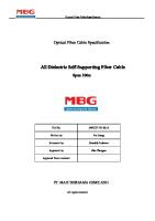
P/Q DIAGRAMS
4.1 P/Q diagram at rated voltage
ABB
Motors and Generators
Type: AMG 1600SS12 DSE Sn: 23019 Un: 11000 f: 50
kVA V Hz
cos: 0.80 n: 500
Tn: 439631 In: 1208,2
rpm
Nm A
P / Q -DIAGRAM 1. Stator current at rated load 2. Nominal working point 3. Active power limit 4. Rated rotor current
5. Minimum excitation limit 6. Stability limit 7. Theoretical stability limit kW 40000
0,8
0,9
0,95
0,95
0,9
0,8
35000 4 1,2
7
30000
6 1,0
25000
1 0,6
0,6
0,75
2
20000
3
0,5
15000 0,4
0,4 0,25
5
10000
0,1
5000
0 -30000
-20000
-10000
0
10000
Document identification
ABB Oy / Motors and Generators
3AFP 89516401
20000
30000
Lang.
en
Rev. ind.
A
TEMPLATE: TECHNICALSPECIFICATION.DOTX; FILENAME: 8951HG_401_A_TECHSPEC.DOCX; PRINTDATE: 8/18/2017 8:21:00 AM; SAVEDATE: 8/18/2017 8:21:00 AM
kVAr
Sheet
11
Status: Approved
Confidential
Document id: DBAE540959 a Page 12 (16)
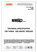
4.2 P/Q diagram at 95% voltage
ABB
Motors and Generators
Type: AMG 1600SS12 DSE Sn: 23019 U: 10450 f: 50
kVA V Hz
cos: 0.80 n: 500
Tn: 439631 In: 1271,8
rpm
Nm A
P / Q -DIAGRAM 1. Stator current at rated load 2. Nominal working point 3. Active power limit 4. Rated rotor current
5. Minimum excitation limit 6. Stability limit 7. Theoretical stability limit kW 40000
0,8
0,9
0,95
0,95
0,9
0,8
35000
4
30000
1,2
7
6 1,0
25000
1 0,6
0,6 0,75
2
20000
3
0,5
15000 0,4
0,4
10000
0,25
5
0,1
5000
0 -30000
-20000
-10000
0
10000
Document identification
ABB Oy / Motors and Generators
3AFP 89516401
20000
30000
Lang.
en
Rev. ind.
A
TEMPLATE: TECHNICALSPECIFICATION.DOTX; FILENAME: 8951HG_401_A_TECHSPEC.DOCX; PRINTDATE: 8/18/2017 8:21:00 AM; SAVEDATE: 8/18/2017 8:21:00 AM
kVAr
Sheet
12
Status: Approved
Confidential
Document id: DBAE540959 a Page 13 (16)
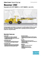
4.3 P/Q diagram at 105% voltage
ABB
Motors and Generators
Type: AMG 1600SS12 DSE Sn: 23019 U: 11550 f: 50
kVA V Hz
cos: 0.80 n: 500
Tn: 439631 In: 1150,7
rpm
Nm A
P / Q -DIAGRAM 1. Stator current at rated load 2. Nominal working point 3. Active power limit 4. Rated rotor current
5. Minimum excitation limit 6. Stability limit 7. Theoretical stability limit kW 45000
0,9
0,95
0,95
0,9
0,8
0,8
40000
35000 4
1,2
7
30000
6 1,0
25000
1 0,75
0,6
0,6
2
20000
3
0,5
15000 0,4
0,4 0,25
10000 0,1
5 5000
0 -30000
-20000
-10000
0
10000
Document identification
ABB Oy / Motors and Generators
3AFP 89516401
20000
30000
Lang.
en
Rev. ind.
A
TEMPLATE: TECHNICALSPECIFICATION.DOTX; FILENAME: 8951HG_401_A_TECHSPEC.DOCX; PRINTDATE: 8/18/2017 8:21:00 AM; SAVEDATE: 8/18/2017 8:21:00 AM
kVAr
Sheet
13
Status: Approved
5
Confidential
Document id: DBAE540959 a Page 14 (16)
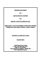
NO LOAD AND SHORT-CIRCUIT CURVE
ABB
Motors and Generators
Type: AMG 1600SS12 DSE Sn: 23019 Un: 11000 f: 50
kVA V Hz
cos: n: Ir (1.0): Ir/Iag (1.0):
0.80 500 199,8 1,100
Tn: In: Ir (1.2): Ir/Iag (1.2):
rpm A
439631 1208,2 270,9 1,243
Nm A A
Excitation current (A) E/Un
I/In
1,4
2,8
1
2
1,2
2,4
3 1
2
0,8
1,6
0,6
1,2
0,4
0,8
1 Air-gap line, Iag 2 No load voltage 3 Short-circuit current
0,2
0,4
0
0 0
200
400
600
800
Document identification
ABB Oy / Motors and Generators
3AFP 89516401
1000
Lang.
en
Rev. ind.
A
TEMPLATE: TECHNICALSPECIFICATION.DOTX; FILENAME: 8951HG_401_A_TECHSPEC.DOCX; PRINTDATE: 8/18/2017 8:21:00 AM; SAVEDATE: 8/18/2017 8:21:00 AM
Ir (A)
Sheet
14
Status: Approved
6
Confidential
Document id: DBAE540959 a Page 15 (16)
COMPLEX SYNCHRONIZING COEFFICIENT
Complex synchronizing coefficient AMG 1600SS12 DSE
k (1/rad) 4.00
1 3.60
3.20 2 2.80
2.40
2.00
1.60 3
4
1.20
00.80
00.40
00.00 0
1
2
3
4
5
6 7 8 9 Oscillation f requency (hz)
10
1 = Sy nch. f actor at rated load 2 = Sy nch. f actor at no load 3 = Damping f actor at rated load 4 = Damping f actor at no load REFERENCE: Dieter Rumpel: Das Drehmomentv erhalten v on Drehstromgeneratoren bei sinusf örmigen Pendelungen, MTZ, 26.Jahrgang Hef t 2 1965 s. 35-42 M/ M=k * d
(9)
k = M / M / d * (cos(e)+j sin(e))
(10)
k = complex sy nchronizing coef f icient, the real part is sy nchronizing (or elastic) f actor, the imaginary part is damping f actor d = the oscillating part of rotor angle in electrial radians d = p * dm, where p = the number of polepairs and dm = the angle in mechanical radian M = the base torque of generator 439630 Nm e = the phase dif f erence angle between the oscillating rotor angle and the corresponding torque
Document identification
ABB Oy / Motors and Generators
3AFP 89516401
Lang.
en
Rev. ind.
A
TEMPLATE: TECHNICALSPECIFICATION.DOTX; FILENAME: 8951HG_401_A_TECHSPEC.DOCX; PRINTDATE: 8/18/2017 8:21:00 AM; SAVEDATE: 8/18/2017 8:21:00 AM
Sheet
15
Status: Approved
7
Confidential
Document id: DBAE540959 a Page 16 (16)
DYNAMIC V-CURVES
Ist-Ir Curves
18.08.2017
AMG 1600SS12 DSE
U = UN
Ist/In 1.50 1
2 3
4 5
6
7 8
9 10
11
1.25
1.00 cap
ind
0.75
0.50
0.25 0.0
0.5
1.0
1.5
2.0
2.5
3.0
3.5
4.0
4.5
5.0
5.5
6.0 Ir/Iri
1: pf 0.50 cap
4: pf 0.90 cap
7: pf 0.95 ind
10: pf 0.70 ind
2: pf 0.70 cap
5: pf 0.95 cap
8: pf 0.90 ind
11: pf 0.50 ind
3: pf 0.80 cap
6: pf 1.00
9: pf 0.80 ind
Document identification
ABB Oy / Motors and Generators
3AFP 89516401
Lang.
en
Rev. ind.
A
TEMPLATE: TECHNICALSPECIFICATION.DOTX; FILENAME: 8951HG_401_A_TECHSPEC.DOCX; PRINTDATE: 8/18/2017 8:21:00 AM; SAVEDATE: 8/18/2017 8:21:00 AM
Sheet
16