![AS-NZS 1163-2016 Cold-Formed Structural Steel Hollow Sections [PDF]](https://pdfs.asia/img/200x200/as-nzs-1163-2016-cold-formed-structural-steel-hollow-sections.jpg)
4 0 2 MB
AS/NZS 1163:2016
AS/NZS 1163:2016
Australian/New Zealand Standard™ Cold-formed structural steel hollow sections
AS/NZS 1163:2016 This Joint Australian/New Zealand Standard was prepared by Joint Technical Committee BD-023, Structural Steel. It was approved on behalf of the Council of Standards Australia on 13 January 2016 and on behalf of the Council of Standards New Zealand on 21 January 2016. This Standard was published on 5 April 2016.
The following are represented on Committee BD-023: Australian Chamber of Commerce and Industry Australian Industry Group Australian Steel Association Australian Steel Institute Austroads Bureau of Steel Manufacturers of Australia Business New Zealand New Zealand Heavy Engineering Research Association Steel Construction New Zealand University of New South Wales University of Sydney
Keeping Standards up-to-date Standards are living documents which reflect progress in science, technology and systems. To maintain their currency, all Standards are periodically reviewed, and new editions are published. Between editions, amendments may be issued. Standards may also be withdrawn. It is important that readers assure themselves they are using a current Standard, which should include any amendments which may have been published since the Standard was purchased. Detailed information about joint Australian/New Zealand Standards can be found by visiting the Standards Web Shop at www.saiglobal.com.au or Standards New Zealand web site at www.standards.co.nz and looking up the relevant Standard in the on-line catalogue. For more frequent listings or notification of revisions, amendments and withdrawals, Standards Australia and Standards New Zealand offer a number of update options. For information about these services, users should contact their respective national Standards organization. We also welcome suggestions for improvement in our Standards, and especially encourage readers to notify us immediately of any apparent inaccuracies or ambiguities. Please address your comments to the Chief Executive of either Standards Australia or Standards New Zealand at the address shown on the back cover.
This Standard was issued in draft form for comment as DR AS/NZS 1163.
AS/NZS 1163:2016
Australian/New Zealand Standard™ Cold-formed structural steel hollow sections
Originated in Australia as AS A177—1969. Previous and first joint edition AS/NZS 1163:2009. Fifth edition 2016.
COPYRIGHT © Standards Australia Limited/Standards New Zealand All rights are reserved. No part of this work may be reproduced or copied in any form or by any means, electronic or mechanical, including photocopying, without the written permission of the publisher, unless otherwise permitted under the Copyright Act 1968 (Australia) or the Copyright Act 1994 (New Zealand). Jointly published by SAI Global Limited under licence from Standards Australia Limited, GPO Box 476, Sydney, NSW 2001 and by Standards New Zealand, PO Box 10729, Wellington 6011.
ISBN 978 1 76035 432 9
AS/NZS 1163:2016
2
PREFACE This Standard was prepared by the Standards Australia/Standards New Zealand Committee BD-023, Structural Steel, to supersede AS/NZS 1163:2009. The objective of this Standard is to specify the requirements for manufacturers and suppliers of longitudinal welded cold-formed structural steel hollow sections for general structural and engineering applications. This edition incorporates the following major changes to the previous edition: (a)
Requirements for type testing and minimum production testing and inspections have been included in the normative Appendix on product conformity.
(b)
Test certificates are required to be available for all products produced to this Standard.
(c)
Alignment of definitions associated with test unit, test product, test sample, test specimen and test piece as noted in ISO 404, AS/NZS 3678, AS/NZS 3679.1 and AS/NZS 3679.2.
(d)
Inclusion of notations and additional definitions in Section 3.
(e)
The inclusion of cold-rolled and annealed coil with hot-rolled coil for steel feed.
(f)
Revision to the chemical composition part of the Standard, which includes a new set of limits for finished product analysis.
(g)
Provisions for suitability for zinc coating have been moved to the Appendix on purchasing guidelines.
(h)
Reformatting of the freedom from defects and testing provisions of the Standard.
(i)
Inclusion of the provision for individual length markings for New Zealand.
(j)
Minor revision to test and inspection certificates.
(k)
A new Appendix on formulae for calculating cross-section properties.
(l)
Definitions, clause numbering and layout across the four steel-product Standards AS/NZS 1163, AS/NZS 3678, AS/NZS 3679.1 and AS/NZS 3679.2 are consistent wherever possible.
A statement expressed in mandatory terms in a note to a table is deemed to be a requirement of this Standard. The terms ‘normative’ and ‘informative’ have been used in this Standard to define the application of the appendix to which they apply. A ‘normative’ appendix is an integral part of a Standard, whereas an ‘informative’ appendix is only for information and guidance.
3
AS/NZS 1163:2016
CONTENTS Page 1
SCOPE ........................................................................................................................ 4
2
NORMATIVE REFERENCES ................................................................................... 4
3
DEFINITIONS AND NOTATIONS ........................................................................... 5
4
DESIGNATION .......................................................................................................... 9
5
MANUFACTURING PROCESS ................................................................................ 9
6
CHEMICAL COMPOSITION .................................................................................. 10
7
MANUFACTURING TOLERANCES ...................................................................... 11
8
FREEDOM FROM DEFECTS .................................................................................. 17
9
TESTING .................................................................................................................. 18
10
MECHANICAL PROPERTIES ................................................................................ 21
11
IDENTIFICATION, TEST AND INSPECTION CERTIFICATES ........................... 22
12
SAMPLING AND TESTING TO DEMONSTRATE PRODUCT CONFORMITY .. 24
13
ROUNDING OF NUMBERS .................................................................................... 24
14
MANIPULATION .................................................................................................... 24
15
SECTION DESIGNATIONS, NOMINAL DIMENSIONS, CROSS-SECTION PROPERTIES AND MASSES .................................................................................. 24
APPENDICES A PURCHASING GUIDELINES .................................................................................. 25 B PRODUCT CONFORMITY ...................................................................................... 27 C MANIPULATION ..................................................................................................... 34 D SECTION DESIGNATIONS, DIMENSIONS AND CROSS-SECTION PROPERTIES ............................................................................................................ 35 E FORMULAE FOR THE CALCULATION OF SECTIONAL PROPERTIES............ 45 BIBLIOGRAPHY ..................................................................................................................... 48
AS/NZS 1163:2016
4
STANDARDS AUSTRALIA/STANDARDS NEW ZEALAND Australian/New Zealand Standard Cold-formed structural steel hollow sections 1 SCOPE This Standard specifies the requirements for the production and supply of cold-formed, electric resistance-welded, steel hollow sections used for structural purposes. It considers three strength grades, with or without impact properties, that are suitable for welding. This Standard applies to structural hollow sections formed cold without subsequent heat treatment. This Standard is intended for general structural and engineering applications. All grades specified in this Standard are suitable for— (a)
welding, in accordance with AS/NZS 1554, Parts 1, 2, 5 and 7; and
(b)
fastening, as specified in AS 3990, AS 4100, AS/NZS 4600, AS 5100.6 and NZS 3404.
The Standard does not cover— (i)
submerged arc-welded;
(ii)
helically welded; or
(iii) U’ed and O’ed steel hollow sections. Requirements for product conformity to this Standard are given in Appendix B. Requirements for cold-bending of galvanized circular hollow sections are given in Appendix C. NOTE: Guidelines to purchasers on requirements that should be specified by the purchaser and those that should or may be agreed on at the time of enquiry and order are given in Appendix A.
2 NORMATIVE REFERENCES The following normative documents are referenced in this Standard: NOTE: Documents referenced for informative purposes are listed in the Bibliography.
AS 1391
Metallic materials—Tensile testing at ambient temperature
1544 1544.2
Methods for impact tests on metals Part 2: Charpy V-notch
1733
Methods for the determination of grain size in metals
2706
Numerical values—Rounding and interpretation of limiting values
3990
Mechanical equipment—Steelwork
4100
Steel structures
5100 5100.6
Bridge design Part 6: Steel and composite construction
AS/NZS 1050 1050.1
Methods for the analysis of iron and steel (series) Part 1: Sampling iron and steel for chemical analysis
COPYRIGHT
5
AS/NZS 1163:2016
AS/NZS 1554 1554.1 1554.2 1554.5 1554.7
Structural steel welding Part 1: Welding of steel structures Part 2: Stud welding (steel studs to steel) Part 5: Welding of steel structures subject to high levels of fatigue loading Part 7: Welding of sheet steel structures
4600
Cold-formed steel structures
ISO 643
Steels—Micrographic determination of the apparent grain size
2566 2566-1
Steel—Conversion of elongation values Part 1: Carbon and low alloy steels
7870 7870-3
Control charts Part 3: Acceptance control charts
10893 10893-2
Non-destructive testing of steel tubes Part 2: Automated eddy current testing of seamless and welded (except submerged arc-welded) steel tubes for the detection of imperfections Part 3: Automated full peripheral flux leakage testing of seamless and welded (except submerged arc-welded) ferromagnetic steel tubes for the detection of longitudinal and/or transverse imperfections Part 11: Automated ultrasonic testing of the weld seam of welded steel tubes for the detection of longitudinal and/or transverse imperfections
10893-3
10893-11 14284 NZS 3404 3404.1
Steel and iron—Sampling and preparation of samples for the determination of chemical composition Steel Structures Standard Part 1: Materials, fabrication and construction
3 DEFINITIONS AND NOTATIONS The notations used in this Standard are listed in Table 1. For the purpose of this Standard, the definitions below apply. 3.1 Analysis 3.1.1 Cast analysis Chemical analysis determined from test samples taken from the ladle, tundish or mould during casting. 3.1.2 Product analysis Chemical analysis determined from a test sample of the finished product. 3.2 Batch Hollow sections of the same size, nominal thickness and grade manufactured from the same heat, tube forming process (tube mill) and rolling (roll set up). 3.3 Can To denote a capability or possibility that is available or that might occur. 3.4 Cold-formed hollow section Hollow section formed and shaped at ambient temperature from a single strip of steel, both edges of which are continuously welded by the contact tip or induction coil electric resistance process. COPYRIGHT
AS/NZS 1163:2016
6
3.5 Cold-rolled and annealed coil Flat product manufactured by cold-rolling and subsequent annealing of hot-rolled coil. Cold-rolled coil is hot-rolled coil that has been subjected to a cold-rolling reduction of more than 15%. The coil shall have a subcritical annealing cycle that recrystallises the structure and forms new ferrite grains. The resulting properties are similar to hot-rolled coil. 3.6 Crack Narrow line of fracture on the surface. 3.7 Defects Surface discontinuities, including cracks, laps and seams, in the base material and out-of-tolerance weld seams. 3.8 Factory production control Operational techniques and all measures necessary to regulate and maintain the conformity of the product to the requirements of the relevant product Standard. 3.9 Fine grained steels Steels which have an austenitic grain size of number 6 or finer when tested in accordance with AS 1733. Generally, steels are considered fine grained without the need for testing when the total aluminium content is greater than 0.020%, or when niobium ≥ 0.01%, titanium ≥ 0.01% or vanadium ≥ 0.02% are deliberately added as carbonitride formers. NOTE: AS 1733 includes various recognized methods for grain size determination, including the McQuaid-Ehn method, and appropriate etching techniques.
3.10 Heat A product of a ladle of steel melted in one vessel and processed under the same conditions. 3.11 Hot-rolled coil Flat product manufactured by hot-rolling semi-finished products. Includes products that have been subjected to a light cold-rolling pass, normally less than 5% reduction, known as a ‘skin pass’. 3.12 Inspection Judgement by competent personnel to determine acceptability against requirements. 3.13 Lap Overlapping material partially connected with the base material. 3.14 Longitudinal direction Direction parallel to the longitudinal weld seam. 3.15 Longitudinal weld seam Continuous weld joining both edges of the single strip of steel used to form a hollow section. 3.16 Manufacturer The business operating either the steel feed (Clause 5.1) or the finished product (Clause 5.2) manufacturing process. 3.17 May Indicates the existence of an option.
COPYRIGHT
7
AS/NZS 1163:2016
3.18 Purchaser Organization or person who is a recipient from a supplier of a steel product manufactured to this Standard. 3.19 Seams (defect) Caused when defects in the semi-finished product are elongated and extended during rolling. 3.20 Shall Indicates that a statement is mandatory. 3.21 Should Indicates a recommendation. 3.22 Structural hollow sections Tube intended to be used for structural purposes. 3.23 Supplier An organization or person that provides a steel products manufactured to this Standard. 3.24 Testing Chemical analysis tests and mechanical tests undertaken by an accredited laboratory as required by this Standard. 3.25 Test piece Piece prepared for testing, made from a test specimen by a mechanical operation. 3.26 Test sample Portion of material or product, or a group of items selected from a test batch or group by a sampling procedure. 3.27 Test specimen Portion or a single item taken from the test sample for the purpose of eventually applying a particular test. 3.28 Transverse direction Direction at right angles to the longitudinal weld seam. 3.29 Type testing Testing performed to prove that the material is capable of conforming to the requirements of this Standard. 3.30 Unit Length of hollow section.
COPYRIGHT
AS/NZS 1163:2016
8
TABLE 1 NOTATION Symbol A A EL A EM
Unit mm
2
2
m /m 2
m /t 2
A cri
mm
A cro
mm 2
Ag
mm
2 2
Description cross-sectional area external surface area per unit length external surface area per unit mass intermediate term for the calculation of internal corner radius properties intermediate term for the calculation of external corner radius properties gross area of the cross-section
Ah
mm
b
mm
nominal side dimension of a square hollow section (SHS) or shorter side of a rectangular hollow section (RHS)
C
mm 3
torsion modulus
c1, c2
mm
length of external corner profile of a square or rectangular hollow section
d
mm
nominal dimension of the longer side of a rectangular hollow section (RHS)
di
mm
inside diameter of a circular hollow section (CHS) (for calculation purposes)
do
mm
nominal outside diameter of a circular hollow section
d omax . , d omin .
mm
maximum and minimum outside external diameter of a circular hollow section, measured in the same plane
e
mm
deviation from straightness
h cri
mm
intermediate term for the calculation of internal corner radius properties
h cro
mm
intermediate term for the calculation of external corner radius properties
I
mm
4 4
I cri
mm
I cro
mm 4
J
mm
4 2
intermediate term for the calculation of J and C
second moment of area intermediate term for the calculation of internal corner radius properties intermediate term for the calculation of external corner radius properties torsion constant (polar moment of inertia for circular hollow sections only)
K
mm
L
mm
length
Lo
mm
gauge length
m
kg/m
mass per unit length
n
—
diagonal axis passing through the opposing corner radii of a square hollow section (SHS)
o
%
out-of-roundness
Rc
mm
average of outer and inner corner radius for calculation purposes
r
mm
radius of gyration
ri
mm
internal corner radius of a square or rectangular hollow section (for calculation purposes)
ro
mm
external corner radius of a square or rectangular hollow section
3
intermediate term for the calculation of J and C
S
mm
plastic section modulus
So
mm 2
original cross-sectional area
t
mm
nominal thickness
v
mm
total twist (continued)
COPYRIGHT
9
AS/NZS 1163:2016
TABLE 1 (continued) Symbol
Unit
v1
mm
twist measured at one end of a section
x
—
major principal axis
x1
mm
concavity of a side of a square or rectangular hollow section
x2
mm
convexity of a side of a square or rectangular hollow section
y
—
minor principal axis 3
Description
Z
mm
elastic section modulus
θ
degrees
angle between adjacent sides of a square or rectangular hollow section
π
3.14159
pi
4 DESIGNATION All grades shall be designated in the format shown in the following: Examples: AS/NZS 1163–C350 AS/NZS 1163–C350L0 where AS/NZS 1163 = number of this Standard C
= cold-formed sections
350
= minimum yield strength in MPa (see Table 7)
L
= guaranteed impact properties of the material (when applicable)
0
= low temperature impact test at 0°C (when applicable)
5 MANUFACTURING PROCESS 5.1 Steel feed The steel shall be made by the basic oxygen process or an electric arc process. Additional refining by vacuum arc remelt, electroslag refining or secondary steelmaking practices such as vacuum degassing or calcium injection, or both, is permitted. The steel shall be fine grained and be made from fully killed, continuously cast steels. The coil shall be hot-rolled coil from a hot strip mill. Further processing of the coil by coldrolling and annealing is permitted. Cold-rolled coil is hot-rolled coil that has been subjected to a cold-rolling reduction of more than 15%. The coil shall have a subcritical annealing cycle that recrystallizes the structure and forms new ferrite grains. The resulting properties are similar to hot-rolled coil. 5.2 Finished product The finished hollow section product shall be manufactured by the cold-forming process and use electric resistance-welding techniques to join the strip edges. The weld seam is to be longitudinal and shall have the external upset removed. There shall be no subsequent overall heat treatment on the finished product.
COPYRIGHT
AS/NZS 1163:2016
10
6 CHEMICAL COMPOSITION 6.1 General The method of sampling for chemical analysis shall be in accordance with AS/NZS 1050.1 or ISO 14284. Chemical composition shall be determined in accordance with AS/NZS 1050 series Standards or other procedures that achieve the same, or better, degree of accuracy. 6.2 Cast analysis A cast analysis of the steel shall be made from each heat to determine the proportions of the specified elements. In cases where it is impracticable to obtain samples from the liquid steel, analysis on test samples taken in accordance with AS/NZS 1050.1 or ISO 14284 may be reported as cast analysis. The cast analysis of the steel shall conform to the limits given in Table 2 for the appropriate grade. 6.3 Product analysis Chemical analysis of the finished product is not a requirement of this Standard. If the steel is subjected to a finished product analysis, the chemical composition shall conform to the limits given in Table 2 with the tolerances given in Table 3. TABLE 2 CHEMICAL COMPOSITION Grades (see Note 1)
Chemical composition (cast or product analysis) (see Note 2) % max. Al (see Note 3)
Ti
Micro-alloying elements
CE (see Note 4)
0.50 0.03 0.03 0.15 0.10
0.10
0.04
0.03 (see Note 5)
0.25
1.60 0.03 0.03 0.30 0.10
0.10
0.04
0.15 (see Note 6)
0.43
0.25 1.70 0.03 0.03 0.30 0.35 (see Note 7)
0.10
0.04
0.15 (see Note 6)
0.43
C
Si
C250, C250L0
0.12
0.05
C350, C350L0
0.20
0.25
C450, C450L0
0.20
Mn
P
S
Cr
Mo
NOTES: 1
The use of sulphide modification manufacturing techniques for these grades is permitted.
2
The following elements may be present to the limits stated: (a)
Copper
0.25%.
(b)
Nickel
0.25%.
3
Limits specified are for soluble or total aluminium.
4
Carbon equivalent (CE) is calculated from the following equation:
CE = C +
Mn Cr + Mo + V Ni + Cu + + 6 5 15
5
Applies to niobium and vanadium only. However, niobium greater than 0.010% is not permitted.
6
Applies to niobium, vanadium and titanium only. However, vanadium greater than 0.10% is not permitted.
7
For circular hollow sections (CHS), the silicon limit shall be 0.45.
COPYRIGHT
11
AS/NZS 1163:2016
TABLE 3 PRODUCT ANALYSIS TOLERANCES FOR GRADES GIVEN IN TABLE 2 Tolerance over maximum limit %
Element Carbon
0.02
Silicon
0.05
Manganese
0.10
Phosphorous
0.005
Sulphur
0.005
Chromium
0.05
Nickel
0.05
Molybdenum
0.03
Copper
0.04 −0.005
Aluminium (total) Micro-alloying elements (niobium and vanadium only) for Grades C250, C250L0 Micro-alloying elements (niobium, vanadium and titanium only) for Grades C350, C350L0, C450, C450L0
0.06 with niobium no greater than 0.020 0.19 with vanadium no greater than 0.12
7 MANUFACTURING TOLERANCES 7.1 General Tolerances and limits on the dimensions and mass of cold-formed hollow sections shall conform with the values given in— (a)
Table 4, for shape and mass;
(b)
Table 5, for external corner profiles; and
(c)
Table 6, for length.
Where relevant, Tables 4, 5 and 6 shall be read in conjunction with Clause 7.2. The internal corners of square and rectangular hollow sections shall be rounded. NOTE: The internal corner profile is not specified.
COPYRIGHT
AS/NZS 1163:2016
12
TABLE 4 TOLERANCES FOR SHAPE AND MASS Characteristic External dimensions (d o , d and b)
Circular hollow sections
Square and rectangular hollow sections
±1%, with a minimum of ±0.5 mm and a maximum of ±10 mm
±1%, with minimum of ±0.5 mm
For d o ≤ 406.4 mm: ±10%
Thickness (t)
±10%
For d o > 406.4 mm: ±10% with a max of ±2 mm ±2% for hollow sections having a diameter to thickness ratio not exceeding 100 (see Note 1)
—
Concavity/convexity (see Note 2)
—
Max. 0.8% or 0.5 mm, whichever is greater
Squareness of sides
—
90°±1°
External corner profile
—
See Table 5
Twist (v)
—
2 mm + 0.5 mm/m length
0.20% of total length
0.15% of total length
Out-of-roundness (o)
Straightness (see Note 3) Mass (m) per unit length
Not less than 0.96 times the specified mass (Note 4) on individual lengths
NOTES: 1
Where the diameter to thickness ratio exceeds 100, the tolerance on out-of-roundness becomes the subject of agreement between the manufacturer and purchaser.
2
The tolerance on convexity and concavity is independent of the tolerance on external dimensions.
3
The straightness tolerance applies to straightness in any one plane.
4
In lieu of any other requirement, the specified mass is considered to be the nominal mass as noted in Clause 15.
TABLE 5 EXTERNAL CORNER PROFILE Perimeter
External corner profile (c 1 , c 2 or r o ) (see Note)
mm
mm
Equivalent to 50 × 50 or less
1.5t to 3.0t
Equivalent to greater than 50 × 50
1.8t to 3.0t
NOTE: The sides need not be tangential to the corner arcs.
COPYRIGHT
13
AS/NZS 1163:2016
TABLE 6 TOLERANCES ON LENGTH (see Note) Range mm
Type of length Random length
Tolerance
4000 to 16 000 with a range of 2000 per order item
Mill (or ‘unspecified’) length
10% of sections supplied may be below the minimum for the ordered range but not less than 75% of the minimum +100 mm –0
All
Precision length
10 000
NOTE: The enquiry and order shall indicate the type of length required and the length or length range, as appropriate. Alternatively, length tolerances shall be specified at the time of order.
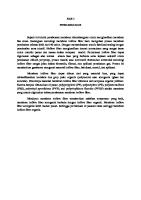
7.2 Measurement of size and shape 7.2.1 General All external dimensions shall be measured at a distance from the end of the hollow section of not less than do for circular sections, b for square sections and d for rectangular sections, with a minimum of 100 mm. 7.2.2 External dimensions For circular hollow sections, the diameter (do) shall be measured. The limiting cross-sectional positions for measuring b and d of square and rectangular hollow sections are shown in Figure 1. NOTE: A caliper gauge, circumference tape or other suitable device may be used at the discretion of the manufacturer.
M e a s u r e m e nt of ` b, d ´ i n h e r e
M e a s u r e m e nt of ` t ´ i n h e r e c1
5
5
c1
t
c2 5
b
b, d
NOTE: The 5 mm dimension is a maximum when measuring b or d, and a minimum when measuring t. DIMENSIONS IN MILLIMETRES
FIGURE 1 LIMITING CROSS-SECTIONAL POSITIONS FOR MEASURING DIMENSIONS b, d AND t FOR SQUARE OR RECTANGULAR HOLLOW SECTIONS COPYRIGHT
AS/NZS 1163:2016
14
7.2.3 Thickness The thickness (t) shall be measured at a position of not less than 2t or 25 mm, whichever is lesser, from the weld seam. The limiting cross-sectional positions for measuring the thickness of square and rectangular hollow sections are shown in Figure 1. NOTE: Thickness is normally measured within a distance of half the outside diameter or half the longer side length from the end of the section.
7.2.4 Out-of-roundness The out-of-roundness (o) of a circular hollow section shall be calculated as a percentage, from the following equation: o=
d omax . − d omin . do
× 100
. . . 7.2.4
7.2.5 Concavity and convexity The concavity (x1) or the convexity (x2) of the sides of a square or rectangular hollow section shall be measured as shown in Figure 2. The percentage concavity or convexity shall be calculated as follows:
x1 × 100% b x2 × 100% b x1 × 100% d x2 × 100% d where b and d are the lengths of the sides containing the concavity (x1) or the convexity (x2).
b, d c 1, c 2 c 1, c 2
x1
x2 A
x2
B
A
B x1
FIGURE 2 MEASUREMENT OF CONCAVITY/CONVEXITY OF SQUARE OR RECTANGULAR HOLLOW SECTIONS
COPYRIGHT
15
AS/NZS 1163:2016
7.2.6 Squareness of sides The deviation from squareness of the sides of a square or rectangular hollow section is defined as the difference between 90° and θ as shown in Figure 3.
θ
D evi ati o n f r o m s q u a r e n e s s = 9 0 ° - θ
FIGURE 3 SQUARENESS OF SIDES OF SQUARE OR RECTANGULAR HOLLOW SECTIONS
7.2.7 External corner profile The external corner profile of a square or rectangular hollow section shall be measured at the discretion of the manufacturer, as follows: (a)
Measure the external corner radius (ro). Use a radius gauge or other suitable device.
(b)
Measure the length of the external corner profile (c1 and c2) (see Figure 4).
ro c2 c1 A
A
NOTE: c1 and c2 can be measured as the distance between the intersection of the flat side and the corner arc and the intersection of the line projections of the flat sides to the corner.
FIGURE 4 EXTERNAL CORNER PROFILE OF SQUARE OR RECTANGULAR HOLLOW SECTIONS
COPYRIGHT
AS/NZS 1163:2016
16
7.2.8 Twist The total twist (v) in a square or rectangular hollow section shall be determined, at the discretion of the manufacturer, as follows: (a)
Place the hollow section on a horizontal surface with one side at one end pressed flat against the surface. At the opposite end of the hollow section, determine the difference of v in the height of the two lower corners from a horizontal surface (see Figure 5).
(b)
Measure v with a spirit level and micrometer (screw) gauge or other suitable device. The reference length of the spirit level shall be the distance between the intersection of the flat sides and the external corner profile (see Figure 6). v is the difference between the values v1 (see Figure 6) measured at each end of the section.
v
FIGURE 5 TOTAL TWIST OF SQUARE OR RECTANGULAR HOLLOW SECTIONS
1
v1
2 3
Le g e n d: 1 S p i r i t l eve l 2 Mi c r o m e te r g a u g e 3 d fo r r e c t a n g u l a r s e c ti o n s , b fo r s q u a r e s e c ti o n s
FIGURE 6 MEASUREMENT OF TWIST
7.2.9 Straightness The deviation from straightness (e) of the total length of a hollow section shall be measured at the point of maximum departure of the section from a straight line connecting its two ends, as shown in Figure 7. The percentage deviation from straightness shall be calculated as follows:
e × 100% L
COPYRIGHT
17
AS/NZS 1163:2016
e L
FIGURE 7 MEASUREMENT OF DEVIATION FROM STRAIGHTNESS
7.2.10 Removal of the external weld seam upset After removal of the external weld upset, the remaining weld seam (excluding the upset beyond the inner surface) and wall thickness in the adjacent area shall not be less than 90% of the nominal wall thickness. 8 FREEDOM FROM DEFECTS 8.1 General The finished product shall be free from defects that are detrimental to the material’s structural integrity. 8.2 Weld seam 8.2.1 Position For rectangular and square hollow sections, the weld seam shall not be placed within a distance of three times the wall thickness from the apex of the corner radius. NOTES: 1 The apex of the corner radius is defined as the intersection point of the lines emanating from two external adjoining faces of the hollow section. 2 Some end-use applications may require the weld seam to be placed close to the corner radius. This should be noted at the time of enquiry or order (see Appendix A) with the finished hollow sections not exhibiting any cracking or brittle behaviour. For the adequate performance of the corner radius and weld seam, such hollow sections are not considered to be in the scope of this Standard.
8.2.2 Non-destructive examination At the manufacturer’s discretion, the weld seam of welded structural hollow sections may be subjected to non-destructive examination (NDE). The NDE may be carried out either on the circular shape prior to final forming or on the hollow sections after final forming. Where NDE is employed, the weld seam shall be tested in accordance with one of the following: (a)
ISO 10893-2 to acceptance Level L4, except that the rotating tube/pancake coil technique shall not be permitted.
(b)
ISO 10893-3 or ISO 10893-11, with the exception that the acceptance level shall be based on, at minimum, the use of N 15 internal/external notches and for the application of ISO 10893-3, a notch of no greater than twice the depth of the reference notch, with a maximum of 1.0 mm, shall apply.
8.3 Removal of surface defects When removal of surface defects by grinding is adopted, the ground area shall be welltransitioned and the remaining wall thickness in the ground areas shall be not less than 90% of the nominal thickness.
COPYRIGHT
AS/NZS 1163:2016
18
8.4 Weld repair of surface defects Welding used in the repair of surface defects shall utilize a low-hydrogen process in accordance with AS/NZS 1554.1. Welds shall be sound, the weld being thoroughly fused without undercutting or overlap. The weld metal shall project at least 1.5 mm above the rolled surface and the projecting metal shall be removed by grinding flush with the rolled surface. 9 TESTING 9.1 Selection of test samples Test samples for the preparation of test pieces for tensile, impact and cold-flattening tests shall be taken in accordance with Clause 9.2. Subject to the requirements of Clause 9.3.4, test pieces shall be in the same condition as the finished product. Test samples shall be representative of the body of the product. 9.2 Position and orientation of test pieces 9.2.1 Tensile test and impact test The test piece shall be cut such that the major axis is in the longitudinal direction and shall be selected from any position along the length of the test specimen such that the requirements of Clause 9.3.2 or 9.3.3 are complied with. 9.2.2 Cold flattening test The test piece shall be cut in the transverse direction and shall be cut from one end of a test specimen that contains a longitudinal weld seam. 9.3 Preparation of test pieces for mechanical testing 9.3.1 General Test specimens may be straightened cold before preparation in accordance with this Standard. A test piece which shows defective machining or develops flaws may be discarded and another test specimen may be submitted. 9.3.2 Tensile test piece 9.3.2.1 Form of test piece The test piece shall be in the form given in either Item (a) or (b) as follows: (a)
A test piece with dimensions conforming to those specified in Table C2 of AS 1391—2007, cut from the test specimen. The cross-section location of the test specimen shall be as specified in Clauses 9.3.2.2 or 9.3.2.3, as appropriate.
(b)
A length of the full section test specimen.
The test piece shall be aged in accordance with Clause 9.3.4. 9.3.2.2 Circular hollow sections (CHS) For a length of circular hollow section, the test specimen shall be taken at approximately 90° from the weld seam [see Figure 8(a)]. The tensile test piece cut from a test specimen shall not be flattened between gauge marks. 9.3.2.3 Rectangular hollow section (RHS) The tensile test piece cut from a test specimen shall be taken from any side midway between and excluding the corners [see Figure 8(b)]. The test piece shall not include a longitudinal weld seam.
COPYRIGHT
19
AS/NZS 1163:2016
9.3.3 Impact test piece Three test pieces shall be prepared from each test specimen and cut parallel to the longitudinal axis of the hollow section, with the axis of the notch perpendicular to the rolled surface of the section (see Figure 8). For circular and rectangular hollow sections, the cross-section location of the test specimen shall be as specified in Figure 8 where, for rectangular hollow sections, it shall also be remote from the weld seam. The test piece shall be prepared in accordance with AS 1544.2 using, where necessary, the largest practicable subsidiary test piece with a width not less than 5 mm. For a standard sized test specimen (i.e. 10 mm × 10 mm), the finally machined test pieces shall be extracted from the mid-thickness of the hollow section wall. The test piece shall be aged in accordance with Clause 9.3.4. 9.3.4 Ageing treatment Prior to tensile or impact testing, the test pieces shall be aged by heating to a temperature between 150°C and 200°C for not less than 15 min. 9.3.5 Cold flattening test The test piece shall be taken in the form of a cross-section from one end of a finished length of a circular hollow section which contains a longitudinal weld seam. The length of the test piece shall be not less than 40 mm. A l te r n ative p o s i ti o n s
We l d
=
N otc h a x i s
=
N otc h axis =
(a) Ci r c ul a r h o ll ow s e c ti o n
=
( b) R e c t a n g ul a r h o ll ow s e c ti o n
(c) N otc h o r i e nt ati o n fo r i m p a c t te s t s p e c i m e n (a p p li e s to CH S a n d R H S)
FIGURE 8 CROSS-SECTION POSITION OF TEST SPECIMEN FOR TENSILE AND IMPACT TESTS COPYRIGHT
AS/NZS 1163:2016
20
9.4 Mechanical testing 9.4.1 Tensile test A tensile test shall be made on each test piece prepared from each test sample specified in Clause 9.1 The tensile test shall be carried out in accordance with AS 1391. The rate of straining when approaching the yield strength shall be within the limits of the conventional straining rate as specified in AS 1391. Elongation results shall be reported on a gauge length Lo equal to 5.65√So, where So is the original cross-sectional area of the test piece before testing. Conversion of results from a non-proportional gauge length shall be in accordance with ISO 2566-1. For test pieces with cross-sectional area greater than 1000 mm 2, the minimum elongation after conversion to the gauge length of 5.65√So, shall be reduced by 2% from that given in Table 8. 9.4.2 Impact test 9.4.2.1 General One test in accordance with AS 1544.2 shall be carried out on each of three test pieces prepared from each test sample specified in Clauses 9.1 and 9.2. Impact test requirements shall comply with Clauses 9.4.2.2 or 9.4.2.3. 9.4.2.2 Hollow sections with nominal thickness of 6 mm or greater Impact tests shall be performed at 0°C in accordance with AS 1544.2. 9.4.2.3 Hollow sections with nominal thickness less than 6 mm Impact tests are not required at 0°C in accordance with AS 1544.2 subject to satisfying one or both of the following requirements: (a)
The finished product using the same steel feed manufacturer, steel grade, steel processing for hollow sections complying with Clause 9.4.2.2.
(b)
The finished product ferrite grain size shall be greater than or equal to 6 as verified by the method specified in either AS 1733 or ISO 643, when the steel feed is aluminium killed. Alternatively, when aluminium is used as the grain-refining element, the grain size requirement shall be deemed to have been fulfilled if the cast analysis shows the aluminium content to be not less than 0.020% total aluminium, or alternatively, 0.015% soluble aluminium. In these cases, verification of the grain size shall not be required. The above two methods of verification are only acceptable when confirmation of compliance with Clause 5 of this Standard is provided by the manufacturer or supplier.
9.4.3 Cold flattening test The test piece shall be flattened at room temperature between two parallel plane surfaces with the weld seam located as follows in relation to the direction of flattening: (a)
For do ≤ 60 mm: 45 degrees.
(b)
For do > 60 mm: 90 degrees.
The test piece shall be flattened until the distance between the surfaces is 0.75 do or less.
COPYRIGHT
21
AS/NZS 1163:2016
10 MECHANICAL PROPERTIES 10.1 Tensile test When tested in accordance with Clause 9.4.1, the yield strength, tensile strength and elongation of the test piece shall conform to the limits given in Table 8 for the appropriate grade. 10.2 Impact test For impact tests, carried out in accordance with Clause 9.4.2, the absorbed energy values shall conform to the limits given in Table 9. 10.3 Cold flattening test When tested in accordance with Clause 9.4.3, a test piece taken from a circular section with a longitudinal weld seam shall show no signs of cracks or flaws. Superficial ruptures arising from surface defects shall not be cause for rejection. TABLE 7 TENSILE TEST REQUIREMENTS
Minimum yield strength
Grade
Minimum elongation as a proportion of the gauge length of 5.65√So (see Note) %
Minimum tensile strength
Circular hollow sections
Rectangular hollow sections
d o /t
b/t, d/t
MPa
MPa
≤15
>15 ≤30
>30
≤15
>15 ≤30
>30
C250, C250L0
250
320
18
20
22
14
16
18
C350, C350L0
350
430
16
18
20
12
14
16
C450, C450L0
450
500
12
14
16
10
12
14
NOTE: These limits apply to the face from which the tensile test is taken. That is, for RHS, the use of b/t or d/t ratio is dependent on which face the test specimen is cut from. For SHS, there is only one ratio (as b = d).
TABLE 8 CHARPY V-NOTCH IMPACT TEST REQUIREMENTS Minimum absorbed energy, J Test temperature Grade
C250L0 C350L0 C450L0
Size of test piece 10 mm × 10 mm
10 mm × 7.5 mm
10 mm × 5 mm
°C
Average of 3 tests
Individual test
Average of 3 tests
Individual test
Average of 3 tests
Individual test
0
27
20
22
16
18
13
COPYRIGHT
AS/NZS 1163:2016
22
11 IDENTIFICATION, TEST AND INSPECTION CERTIFICATES 11.1 Identification 11.1.1 Individual length markings All hollow section lengths supplied to this Standard shall be clearly and legibly identified by suitable and durable methods, such as painting (e.g. ink jet) or stamping with the following: (a)
The manufacturer’s name or mark, or both.
(b)
The manufacturer’s site or mill identification, or both.
(c)
Unique, traceable text identification, which shall be in either one or both of the following forms:
(d)
(i)
The time and date of manufacture of the product.
(ii)
A serialized identification number for quality control/assurance and traceability purposes.
The markings specified in Items (a), (b) and (c) shall be placed a minimum of once on each length of ex-mill tube.
Where identification is by means of die-stamping, low-stress stamps shall be used for impact tested grades. NOTES: 1 Products not marked with the provisions specified in this Clause are non-compliant with this Standard. 2 If the identified portion of the product is subsequently removed, then these identifications are to be transferred to each remaining portion of the product. 3 Manufacturers making a statement of compliance with this Standard on a product, packaging or promotional material related to that product are advised to ensure that such compliance is capable of being verified.
11.1.2 Bundle/pack markings The material shall be marked or tagged for bundles with the following: (a)
The manufacturer’s name or mark, or both.
(b)
Reference to this Standard, i.e. AS/NZS 1163.
(c)
The grade of steel (see Clause 4).
(d)
The product dimensions to be identified with this Standard (see Appendix D for further details).
(e)
A traceable identification number.
11.2 Test and inspection certificates 11.2.1 General A test and inspection certificate shall be available to the purchaser for all products manufactured to this Standard for each batch produced. 11.2.2 Transmission of test and inspection certificates by an intermediary An intermediary shall only pass on either an original or a copy of the inspection documents provided by the manufacturer without any alteration except as noted below. This documentation shall be accompanied by suitable means of identification of the product, in order to ensure the traceability between the product and the documentation.
COPYRIGHT
23
AS/NZS 1163:2016
Copying of the original document is permitted, provided that— (a)
traceability of product is maintained; and
(b)
the original manufacturer’s document is available on request.
When producing copies of the original manufacturer’s document, it is permissible to replace the original delivered quantity with the subsequent partial quantity. NOTE: In the context of this Standard, an intermediary is a supplier and not a manufacturer (see Clauses 3.23 and 3.16 respectively).
11.2.3 Qualifications on test and inspection certificates A test and inspection certificate shall provide the following: (a)
Tests performed by a laboratory accredited by signatories to the International Laboratory Accreditation Corporation (ILAC) through their Mutual Recognition Arrangement (MRA) for the specific tests described in this Standard. The appropriate logo or further details of the ILAC (MRA) signatory shall be noted on the document. NOTE: In Australia, ILAC (MRA) accredited bodies include National Association of Testing Authorities (NATA) and in New Zealand they include International Accreditation New Zealand (IANZ).
(b)
Additional tests as agreed between the purchaser and manufacturer. NOTE: See Appendix A.
11.2.4 Minimum requirements for test and inspection certificates All test and inspection certificates shall be in English alphanumeric characters, issued by the manufacturer, and include the following: (a)
Manufacturer’s name.
(b)
Test certificate number and test number.
(c)
Date of certification.
(d)
Product, testing specification and grade, e.g. AS/NZS 1163-C350L0 (see Clause 4).
(e)
Product dimensions and size, e.g. 200 × 100 × 5.0 RHS. NOTE: See Appendix D.
(f)
Product steelmaking process, e.g. basic oxygen continuously cast, fine-grained, fully killed steels, and the like (see Clause 5.1).
(g)
Length, bundle, pack or unique identifier to which the test certificate applies (see Clause 11.1).
(h)
Heat number (from steel feed casting).
(i)
For each test a laboratory identification providing traceability to the laboratory accreditation of the test type.
(j)
Chemical analysis type, e.g. ladle and cast analysis ‘L’ or product ‘P’ (see Clauses 6.2 and 6.3).
(k)
Chemical composition of carbon (C), silicon (Si), manganese (Mn), phosphorus (P), sulphur (S), chromium (Cr), molybdenum (Mo), aluminium (Al), titanium (Ti), niobium (Nb), vanadium (V), copper (Cu), nickel (Ni), boron (B), carbon equivalent (CE) and any other element intentionally added (see Clauses 6.1, 6.2, 6.3 and 6.4).
(l)
Where relevant, mechanical and other information as noted below: (i)
Tensile tests to Clause 9.4.1 Orientation, i.e. longitudinal ‘L’ (see Clause 9.2.1), treatment, i.e. aged ‘A’ (see Clause 9.3.4) and results, i.e. yield strength in MPa, tensile strength in MPa and % elongation (see Clause 10.1). COPYRIGHT
AS/NZS 1163:2016
(ii)
24
Impact tests to Clause 9.4.2.2 Orientation, i.e. longitudinal ‘L’ (see Clause 9.2.1), treatment, i.e. aged ‘A’ (see Clause 9.3.4) and results (see Clause 10.2).
(iii) Impact test reporting to Clause 9.4.2.3(a) Statement of steel feed manufacturer name, grade/type, mill location, and other sizes with nominal thickness greater than or equal to 6 mm using the same steel feed type for compliance with Clause 9.4.2.2. (iv)
Impact test reporting to Clause 9.4.2.3(b) Statement of compliance with Clauses 5.1 and 9.4.2.3(b) with, where appropriate, further statements of finished product ferrite grain size, use of aluminium killed steel feed and/or aluminium content in total or soluble form.
(m)
The manufacturing facility’s quality management system’s certifier and certification number.
(n)
The body assessing the product conformity to this Standard. For self-assessment this is the manufacturer, the default scheme is this Standard.
(o)
A declaration from the manufacturer that the products supplied comply with the requirements of this Standard (refer to Clause 12) and Items (a) to (n) above. This shall be validated by the manufacturer’s authorized inspection representative, including their name and position. If the document has been validated by the purchaser’s authorized representative or by an inspector designated by a third party, their name and position shall be on the document.
12 SAMPLING AND TESTING TO DEMONSTRATE PRODUCT CONFORMITY The minimum sampling and testing procedures shall conform to Appendix B. Additional testing may be agreed between the manufacturer and the purchaser. 13 ROUNDING OF NUMBERS 13.1 General For the purpose of deciding whether a particular requirement of this Standard is complied with, the determined value, observed or calculated, shall be rounded off in accordance with AS 2706. The number of significant places retained in the rounded-off values shall be the same as that of the specified value in this Standard. 13.2 Tensile properties The determined value of tensile strength shall be rounded off to the nearest 10 MPa and the determined value of yield strength shall be rounded off to the nearest 5 MPa. 14 MANIPULATION Requirements for cold-bending of galvanized circular hollow sections are given in Appendix C. 15 SECTION DESIGNATIONS, PROPERTIES AND MASSES
NOMINAL
DIMENSIONS,
CROSS-SECTION
Appendix D provides data on section designation, nominal section dimensions, crosssections properties and mass.
COPYRIGHT
25
AS/NZS 1163:2016
APPENDIX A
PURCHASING GUIDELINES (Informative) A1 GENERAL Australian/New Zealand Standards are intended to include the technical provisions necessary for the supply of materials referred to in the particular Standard, but do not purport to comprise all the necessary provisions of a contract. The purchaser may specify additional requirements or be given a choice of optional requirements. These are contractual matters to be agreed upon between the purchaser and the manufacturer, or the supplier. This Appendix contains detailed explanations, advice and recommendations on the information to be supplied by the purchaser at the time of enquiry and order. The objective of this Appendix is to avoid misunderstandings and to result in the purchaser receiving satisfactory products and services. A2 INFORMATION TO BE SUPPLIED BY THE PURCHASER The purchaser should consider and supply the following information at the time of order, after making due reference to the explanation, advice and recommendations contained in this Appendix: (a)
Quantity and delivery instructions (dates, schedules, delivery point).
(b)
Dimensions of section, e.g. nominal length of long and short side, nominal outside diameter and nominal thickness (see Appendix D).
(c)
Designation of grade and Standard number (see Clause 4).
(d)
Any limitations in respect of packaging, e.g. number or sections per pack, packaging materials.
(e)
Whether a test certificate or test and/or inspection certificate is required (see Clause 11.2).
(f)
Whether documentation certifying (see Appendix B) is required.
(g)
Whether it is the intention of the purchaser to inspect the steel at the manufacturer’s works (see Paragraph A3).
(h)
Any information concerning processing or end use that the purchaser considers would assist the manufacturer.
(i)
Whether a product analysis is required (see Clause 6.3).
(j)
Particular position of the weld seam (see Clause 8.2.1), if required.
(k)
Special mill finish or coating, e.g. galvanized.
(l)
End finish.
(m)
Whether special tolerances on dimensions are required.
(n)
Length of sections (including length tolerance type, see Table 7).
(o)
Zinc coating requirements. As a guide, recommendations for suitable chemistry of steels are provided in Clause 9.1 of AS/NZS 2312.2:2014.
the
COPYRIGHT
product
conformity
requirements
AS/NZS 1163:2016
26
Further information is available from the Galvanizers Association of Australia (GAA) and Galvanizing Association of New Zealand (GANZ). NOTE: Any special or supplementary requirements of this Standard are to be subject to agreement between the purchaser and the manufacturer or the supplier at the time of enquiry and order, and should be stated on the order.
A3 INSPECTION If it is the purchaser’s intention to undertake any of the following functions at the manufacturer’s works, this should be notified at the time of order, and should be accomplished in a manner which will not interfere with the operation of the works. The functions are as follows: (a)
Inspect the product during manufacture.
(b)
Select and identify the test samples.
(c)
Witness the tests being made.
The manufacturer should provide all reasonable facilities to enable the purchaser to be satisfied that the product complies with this Standard. A4 HEAT TREATMENT The mechanical properties of these grades can be affected by any reheating that may be applied for its end use. If it is intended to reheat these grades above 620°C, the purchaser should discuss the application and the proposed reheating treatment with the manufacturer. NOTE: Welding to AS/NZS 1554 Parts 1, 2, 5 and 7 does not affect the mechanical properties of hollow sections manufactured to this Standard.
COPYRIGHT
27
AS/NZS 1163:2016
APPENDIX B
PRODUCT CONFORMITY (Normative) B1 SCOPE This Appendix sets out the means by which product conformity evaluation shall be demonstrated by the manufacturer or supplier by— (a)
initial type testing; and
(b)
factory production control, including a minimum testing and inspection frequency plan.
Testing and inspection of one or two samples does not provide an acceptable representation of actual variability in a batch of unidentified steel. NOTE: The result of testing and inspecting such a sample could fall within or outside the standard range by chance and does not present a valid picture of the characteristics being evaluated.
The product conformity requirements shall enable conformity assessment to be made by a manufacturer or supplier (first party), a user or purchaser (second party), or an independent body (third party), and shall not be dependent on a quality management systems Standard. NOTE: An example of a quality management system Standard is AS/NZS ISO 9001.
B2 INITIAL TYPE TESTING B2.1 General An initial type testing program shall be carried out in accordance with Paragraph B2.2 under the sole responsibility of the manufacturer of the products before they are first placed onto the market. Such a program shall be carried out in each case for grade designation with the highest strength and impact properties which a manufacturer places on the market. Additional programs are required for sections with lower strengths and higher impact property requirements. Initial type testing shall be performed on first application of this Standard. Tests previously performed in accordance with the provisions of this Standard [same product, same characteristic(s) test method, sampling procedure, system of attestation of conformity, etc.] may be taken into account. In addition, the initial type testing shall be performed at the beginning of a new method of production, and/or using a new facility or equipment. B2.2 Minimum sampling and testing plan The initial type testing and inspection program comprises of routine testing and inspection at a higher frequency to establish the capabilities of the manufacturing process to produce the steel product. Table B1 provides the minimum testing and inspection frequency plan for type testing. The results of all type tests shall conform to the requirements of this Standard.
COPYRIGHT
AS/NZS 1163:2016
28
TABLE B1 MINIMUM SAMPLING AND TESTING FREQUENCY PLAN FOR TYPE TESTS AND INSPECTIONS Characteristic
Clause
Requirement
Test Method
Frequency
Designation
4
Steel grade designation correct
Visual
Once
Manufacturing Process
5
Determine steel feed stock and steel making process
Records inspection, or initial supplier letter of compliance
Each heat
AS/NZS 1050.1 and analysis methods
Each heat, minimum of 5 produced after set-up*
Chemical composition
6
Cast or product analysis and residual elements analysis
External dimensions Thickness CHS out-of-roundness RHS/SHS Concavity/convexity Manufacturing tolerances
7
Gauging equipment
RHS/SHS Squareness of sides RHS/SHS External corner profile
Each heat, minimum of 5 produced after set-up*
RHS/SHS Twist
8.1 Freedom from defects
9 and 10.1
11.1.1
*
Mass per unit length
Weighing equipment
Free from laminations, surface flaws and other detrimental defects
Visual inspection
Weld seam position
Visual and
Weld seam defects
Visual and/or Gauging equipment Visual inspection
Continuous
To Clauses 9 and 10
6 tests for each heat for minimum 5 after set-up*
Visual inspection
Each length, or bundle, minimum of 5 produced after set-up*
Cold flattening (CHS with OD ≤ 168.3 mm only) Individual length markings Bundle pack markings
11.1.2
Each tensile test Each heat, minimum of 5 produced after set-up*
Tensile strength, yield stress and elongation
9 and 10.2 Impact toughness 9 and 10.3
Identification and certification
Straight edge, String line and gauges
8.2.1
8.2.2
Mechanical properties
Straightness
Set-up is achieved after the manufacturing process is stable.
B3 PRODUCTION TESTING AND INSPECTION B3.1 Minimum batch testing and inspection All products shall conform to the minimum frequency requirements of production testing as defined in Table B2.
COPYRIGHT
29
AS/NZS 1163:2016
TABLE B2 MINIMUM SAMPLING AND TESTING FREQUENCY PLAN FOR PRODUCTION TESTS AND INSPECTIONS Characteristic
Clause
Requirement Determine steel feed stock and steel making process
Manufacturing process
5
Chemical composition
6
Test Method
Frequency
Records inspection, or initial supplier letter of compliance or ongoing certification
Each heat
AS/NZS 1050.1 and analysis methods
Each heat
Gauging equipment
Once per hour*
Straightedge, string line or gauges
One test per batch
Weighing equipment
One test per size per day
Free from laminations, surface flaws and other detrimental defects
Visual inspection
Every tensile test
Weld seam position
Visual
Continuous
Gauging equipment
One test per batch
NDE
Visual— continuous
Cast or product analysis and other elements analysis External dimensions Thickness CHS out-of-roundness RHS/SHS Concavity/convexity
Manufacturing tolerances
RHS/SHS Squareness of sides 7
RHS/SHS External corner profile RHS/SHS Twist Straightness Mass per unit length
8.1
Freedom from defects
8.2.1
8.2.2 9 and 10.1 Mechanical properties
Weld seam defects Tensile strength, yield strength and elongation
9 and 10.2 Impact toughness 9 and 10.3 11.1.1
Cold flattening
One test per batch
Individual length markings
11.1.2
*
Each hour* Visual inspection
Identification Test and inspection certificates
Refer Notes To Clauses 9 and 10
Bundle/pack markings Test and inspection certificates
11.2
Each pack Visual and records inspection
Each certificate
Time is operating hours.
NOTES: 1
For batch testing: The test sample frequencies for mechanical property testing shall be one sample for the first 50 tonnes of the batch and one additional test for every additional 50 tonnes or part thereof.
2
For statistical sampling, see Paragraph B3.2.
COPYRIGHT
AS/NZS 1163:2016
30
B3.2 Statistical sampling B3.2.1 General Process verification by statistical sampling or alternate methods can be used to demonstrate product conformity where the conditions required by these provisions are met (see also Note 1). Where it can be demonstrated that the type test (see Note 2) of any group of products (see Note 3) manufactured under the same conditions of steel supplier, steel grade, steel processing and tube processing are distributed normally, then it shall be permissible to adopt statistical sampling to verify process acceptance for each product in accordance with ISO 7870-3. For product conformance to this Standard via statistical sampling, the inputs of process acceptance verification, ongoing testing and statistical sampling must be demonstrated and, where applicable, also maintained. To ensure that the process being assessed is in control (see Note 1), a statistically significant number of samples needs to be obtained within a rationally determined time period that is reflective of typical manufacturing practice. Within a defined group, each type of test sample randomly selected shall not exceed a sampling period of three months. Additionally, any sample or sampling that indicates a predicted proportion of nonconforming product in excess of an amount considered within the demonstrated statistical sampling method, shall cause the sampling for that combination of size, thickness and grade to revert to batch sampling rules until it can be demonstrated that the conditions of statistical sampling are valid for that combination. In the event of actual nonconforming test results, the retest provisions of normal batch testing shall also apply. NOTES: 1 Statistical sampling is a procedure that enables decisions to be made about the quality and conformity of batches of items after inspecting or testing only a portion of those items. This procedure will only be valid if the sampling plan has been determined on a statistical basis and the following are met: (a) The sample is drawn randomly from a population of product of known history that enables verification that the product was made from known materials at essentially the same time by essentially the same processes and under essentially the same system of control. (b) For each different situation, a suitable sampling plan is defined. A sampling plan for one manufacturer of given capability and product throughput may not be relevant to another manufacturer producing the same items. In order for statistical sampling to be meaningful to the customer, the manufacturer or supplier needs to demonstrate how the above conditions have been satisfied. Sampling and the establishment of a sampling plan should be carried out in accordance with recognized Standards (e.g. AS 2490, AS 1199, Parts 0 and 1) and methods. Under this approach, ongoing sampling and testing of product shall be directed primarily at monitoring the process to ensure that product outcomes are acceptable, within characteristic ranges as well as stable and under control (e.g. normally distributed). 2 The type test is the measured parameter such as tensile testing, impact testing, etc. These are long term testing plans based on initial testing undertaken to determine overall conformance and other required controls to be put into place (e.g. same steel supply, same manufacturing process) to ensure ongoing compliance. 3 To reduce sampling frequencies, a group of products can consist of an aggregation of batch data from a range of products if it can be demonstrated to be normally distributed.
COPYRIGHT
31
AS/NZS 1163:2016
B3.2.2 Tensile tests B3.2.2.1 General Testing to AS 1391, as noted in Clause 9.4.1, is only considered within Paragraph B3.2.2 for product conformance assessment to tensile testing requirements. B3.2.2.2 Sampling conditions In conjunction with the provisions of Paragraph B3.2.1, statistical sampling shall only be used for a combination of size, thickness and grade where the statistically predicted proportion of nonconforming product is less than 5% at a confidence level of 95%. Changes in steel supplier, steel grade and significant changes in steel or tube processing (e.g. mill) shall necessitate a re-evaluation of the conditions in this Paragraph (B3.2.2.2). B3.2.3 Impact tests B3.2.3.1 General Testing and assessments to— (a)
Clause 9.4.2.2;
(b)
Clause 9.4.2.3(a); and
(c)
the grain size provisions of Clause 9.4.2.3(b),
are only considered within Paragraph B3.2.3 for product conformance assessment to impact testing requirements. B3.2.3.2 Sampling conditions In conjunction with the provisions of Paragraph B3.2.1, statistical sampling shall only be used for a combination of size, thickness and grade where the statistically predicted proportion of nonconforming product is less than 5% at a confidence level of 95%. Changes in steel supplier or steel grade and significant changes in steel or tube processing shall necessitate a re-evaluation of the conditions in this Paragraph (B3.2.3.2). B4 FACTORY PRODUCTION CONTROL B4.1 General The manufacturer shall establish, document and maintain a factory production control (FPC) system to ensure that the products placed on the market conform to the stated performance characteristics. The FPC system shall consist of procedures, regular inspections and tests and/or assessments and the use of the results to control raw and other incoming material or components, equipment, the production process and the product. A quality management system covering the requirements of this Standard shall be considered to satisfy the requirements of an FPC. NOTE: An example of an appropriate quality management system is AS/NZS ISO 9001.
B4.2 Equipment B4.2.1 Testing All weighing, measuring and testing equipment shall be calibrated and regularly inspected according to documented procedures, frequencies and criteria. B4.2.2 Manufacturing All equipment used in the manufacturing process shall be regularly inspected and maintained to ensure use, wear or failure does not cause inconsistency in the manufacturing process. Inspections and maintenance shall be carried out and recorded in accordance with the manufacturer’s written procedures. COPYRIGHT
AS/NZS 1163:2016
32
B4.3 Raw materials The specification of all incoming raw materials shall be documented, as shall the inspection scheme for ensuring their conformity. All manufacturing process and steel feed shall comply with the requirements of Clause 5.1. B4.4 Product testing and evaluation The manufacturer shall establish procedures to ensure that the stated values of all the characteristics are maintained. The characteristics and the means of control shall be in accordance with the minimum requirements listed in Table B2. B5 NONCONFORMING PRODUCTS B5.1 General The manufacturer shall nonconforming product.
have
written
procedures,
specifying
the
processing
of
B5.2 Retests B5.2.1 Tensile test and cold flattening test If a retest is carried out, one or more of the following procedures shall be adopted: (a)
Make two additional tests on test pieces from test specimens taken from the same test sample at a position as near as practicable to the location of the failed test sample. The unit conforms to this Standard provided both additional test pieces conform to Clauses 9.2, 9.3, 9.4, 10.1 and 10.3.
(b)
Make two test samples at random from the remainder of the batch. If the test pieces from both additional samples conform to Clauses 9.2, 9.3, 9.4, 10.1 and 10.3, the remainder of the batch conforms to this Standard. If one of these test samples fails to conform, the steel of the applicable batch does not conform to this Standard.
(c)
Make test samples from each rolled unit of steel and individually test in accordance with this Standard. If the test piece from the additional sample conforms, to Clauses 9.2, 9.3, 9.4, 10.1 and 10.3, the rolled unit of steel conforms to this Standard.
B5.2.2 Impact tests If a retest is carried out, one or more of the following procedures shall be adopted: (a)
If the average value of the three impact test results is less than the specified minimum average, or if one value is less than the specified individual test value given in Table 9, then test three additional test pieces from the original test sample in accordance with Clauses 9.2, 9.3 and 9.4, and add the results to those previously obtained and calculate a new average. If the average value of the six tests is not less than the specified minimum average, and not more than one result of the six tests is below the minimum specified individual test value given in Table 9, then the unit conforms to this Standard.
(b)
Take two further test samples at random from the remainder of the test batch. If the test pieces from both additional samples conform to Clauses 9.2, 9.3, 9.4 and 10.2, then the remainder of the test batch conforms to this Standard. If one of these additional samples fails to conform, the steel of the applicable batch does not conform to this Standard.
(c)
Take test samples from each rolled unit of steel and individually test in accordance with this Standard. If the test piece from the additional sample conforms to Clauses 9.2, 9.3, 9.4 and 10.2, then the rolled unit of steel conforms to this Standard.
COPYRIGHT
33
AS/NZS 1163:2016
B5.3 Repair All repaired product shall be inspected and meet the requirements of this Standard. B6 DOCUMENTATION The results of all testing programs shall be recorded and such records shall be maintained and be made available for inspection for a period of at least 5 years after the date when that last product to which the test program refers to was delivered. Results for initial type testing shall be maintained for the period of manufacture of the product. Documentation shall include information to be supplied to the purchaser, plus manufacturing process, physical and mechanical properties, inspection and testing, and test procedures.
COPYRIGHT
AS/NZS 1163:2016
34
APPENDIX C
MANIPULATION (Normative) Galvanized circular hollow sections of outside diameter ≤60.3 mm and other shaped hollow sections of equivalent dimensions, shall be capable of withstanding a 90° bend around a grooved mandrel having a root radius of 6 times the outside diameter of the circular hollow sections or the section dimension in the plane of the bend for non-circular hollow sections. On completion of the bending operation, the galvanized coating shall show no signs of cracks or flaws.
COPYRIGHT
35
AS/NZS 1163:2016
APPENDIX D
SECTION DESIGNATIONS, DIMENSIONS AND CROSS-SECTION PROPERTIES (Normative) This Appendix provides lists of common cold-formed structural steel hollow sections (SSHS) available in Australia and New Zealand. The lists provide their section designation, respective nominal dimensions, cross-section properties and mass. NOTE: Although they appear in the following tables, certain sizes may not always be available in all grades. Users are advised to check availability before incorporating hollow sections in major designs.
The formulae for calculating sectional properties of sections manufactured to the dimensional tolerances of this Standard, to be used for the purposes of structural design and also listed in this Appendix, are specified in Appendix E. Figures D1 to D4 are not restrictive nor exhaustive. Other SSHS shapes and sizes with different designations and dimensions may be produced to this Standard. Manufacturers shall provide the designation, nominal dimensions, cross-sectional properties and mass for SSHS produced that are not listed in Figures D1 to D4. Where CHS, RHS and SHS are not listed in this Appendix, Appendix E shall be used to evaluate cross-sectional properties and mass.
COPYRIGHT
AS/NZS 1163:2016
do
t
1
2
Designation Outside diameter
Thickness
4
5
6
Ratio
Gross area of cross-section
External surface area
7
8
9
10
11
12
Torsion constant
Torsion modulus
r
J
C
mm
10 mm
About any axis
Per unit Per unit length mass
do t
Second moment Elastic section Plastic section of area modulus modulus
Radius of gyration
36
COPYRIGHT
Mass per unit length
3
do
×
t
m
A EL
mm
×
mm
kg/m
m /m
m /t
610.0 610.0 610.0
× × ×
12.7 CHS 9.5 CHS 6.4 CHS
187 141 95.3
1.92 1.92 1.92
10.2 13.6 20.1
48.0 64.2 95.3
23800 17900 12100
1060 808 553
3490 2650 1810
4530 3430 2330
211 212 213
2130 1620 1110
6970 5300 3620
508.0 508.0 508.0
× × ×
12.7 CHS 9.5 CHS 6.4 CHS
155 117 79.2
1.60 1.60 1.60
10.3 13.7 20.2
40.0 53.5 79.4
19800 14900 10100
606 462 317
2390 1820 1250
3120 2360 1610
175 176 177
1210 925 634
4770 3640 2500
165.1 165.1
× ×
5.4 CHS 5.0 CHS
21.3 19.7
0.519 0.519
24.4 26.3
30.6 33.0
2710 2510
8.65 8.07
105 97.7
138 128
56.5 56.6
17.3 16.1
209 195
2
A EM 2
l
Ag mm
2
6
10 mm
Z 4
3
10 mm
S 3
3
10 mm
3
FIGURE D1 (in part) CIRCULAR HOLLOW SECTIONS (see also Figure D2 for other CHS listings)
6
4
3
10 mm
3
1
2
Designation Mass per unit length
Outside diameter
Thickness
3
4
5
6
Ratio
Gross area of cross-section
External surface area
7
8
9
10
11
12
Torsion constant
Torsion modulus
r
J
C
mm
10 mm
About any axis
Per unit Per unit length mass
do t
Second moment Elastic section Plastic section of area modulus modulus
Radius of gyration
×
t
m
A EL
mm
×
mm
kg/m
m /m
m /t
139.7 139.7
× ×
5.4 CHS 5.0 CHS
17.9 16.6
0.439 0.439
24.5 26.4
25.9 27.9
2280 2120
5.14 4.81
73.7 68.8
97.4 90.8
47.5 47.7
10.3 9.61
114.3 114.3
× ×
5.4 CHS 4.5 CHS
14.5 12.2
0.359 0.359
24.8 29.5
21.2 25.4
1850 1550
2.75 2.34
48.0 41.0
64.1 54.3
38.5 38.9
5.49 4.69
96.1 82.0
101.6 101.6
× ×
5.0 CHS 4.0 CHS
11.9 9.63
0.319 0.319
26.8 33.2
20.3 25.4
1520 1230
1.77 1.46
34.9 28.8
46.7 38.1
34.2 34.5
3.55 2.93
69.9 57.6
88.9 88.9 88.9
× × ×
5.9 CHS 5.0 CHS 4.0 CHS
12.1 10.3 8.38
0.279 0.279 0.279
23.1 27.0 33.3
15.1 17.8 22.2
1540 1320 1070
1.33 1.16 0.963
30.0 26.2 21.7
40.7 35.2 28.9
29.4 29.7 30.0
2.66 2.33 1.93
59.9 52.4 43.3
76.1 76.1 76.1
× × ×
5.9 CHS 4.5 CHS 3.6 CHS
10.2 7.95 6.44
0.239 0.239 0.239
23.4 30.1 37.1
12.9 16.9 21.1
1300 1010 820
0.807 0.651 0.540
21.2 17.1 14.21
29.1 23.1 8.9
24.9 25.4 25.7
1.61 1.30 1.08
42.4 34.2 28.4
60.3 60.3 60.3
× × ×
5.4 CHS 4.5 CHS 3.6 CHS
7.31 6.19 5.03
0.189 0.189 0.189
25.9 30.6 37.6
11.2 13.4 16.8
931 789 641
0.354 0.309 0.259
11.8 10.2 8.58
16.3 14.0 11.6
19.5 19.8 20.1
0.709 0.618 0.517
23.5 20.5 17.2
48.3 48.3 48.3
× × ×
5.4 CHS 4.0 CHS 3.2 CHS
5.71 4.37 3.56
0.152 0.152 0.152
26.6 34.7 42.6
8.9 12.1 15.1
728 557 453
0.170 0.138 0.116
7.04 5.70 4.80
9.99 7.87 6.52
15.3 15.7 16.0
0.340 0.275 0.232
14.1 11.4 9.59
42.4 42.4 42.4
× × ×
4.9 CHS 4.0 CHS 3.2 CHS
4.53 3.79 3.09
0.133 0.133 0.133
29.4 35.2 43.1
8.7 10.6 13.3
577 483 394
0.103 0.0899 0.0762
4.87 4.24 3.59
6.93 5.92 4.93
13.4 13.6 13.9
0.206 0.180 0.152
9.74 8.48 7.19
2
A EM 2
Ag mm
l 2
6
10 mm
Z 4
3
10 mm
S 3
3
10 mm
3
6
4
3
10 mm
3
147 138
37
COPYRIGHT
do
FIGURE D1 (in part) CIRCULAR HOLLOW SECTIONS (see also Figure D2 for other CHS listings) AS/NZS 1163:2016
AS/NZS 1163:2016
do
t
1
2
Designation Mass per unit length
Outside diameter
Thickness
3
4
5
6
7
8
External surface area
9
10
12
Torsion constant
Torsion modulus
r
J
C
mm
10 mm
About any axis Ratio
Per unit Per unit length mass
Gross area of cross-section
do t
Second moment Elastic section Plastic section of area modulus modulus
Radius of gyration
do
×
t
m
A EL
mm
×
mm
kg/m
m /m
m /t
457.0 457.0 457.0
× × ×
12.7 CHS 9.5 CHS 6.4 CHS
139 105 71.1
1.44 1.44 1.44
10.3 13.7 20.2
36.0 48.1 71.4
17700 13400 9060
438 334 230
1920 1460 1010
2510 1900 1300
157 158 159
876 669 460
3830 2930 2010
406.4 406.4 406.4
× × ×
12.7 CHS 9.5 CHS 6.4 CHS
123 93.0 63.1
1.28 1.28 1.28
10.4 13.7 20.2
32.0 42.8 63.5
15700 11800 8040
305 233 161
1500 1150 792
1970 1500 1020
139 140 141
609 467 322
3000 2300 1580
355.6 355.6 355.6
× × ×
12.7 CHS 9.5 CHS 6.4 CHS
107 81.1 55.1
1.12 1.12 1.12
10.4 13.8 20.3
28.0 37.4 55.6
13700 10300 7020
201 155 107
1130 871 602
1490 1140 781
121 122 123
403 310 214
2260 1740 1200
323.9 323.9 323.9
× × ×
2.7 CHS 9.5 CHS 6.4 CHS
97.5 73.7 50.1
1.02 1.02 1.02
10.4 13.8 20.3
25.5 34.1 50.6
12400 9380 6380
151 116 80.5
930 717 497
1230 939 645
110 111 112
301 232 161
1860 1430 994
2
A EM 2
l
Ag
Z
S
38
COPYRIGHT
11
mm
2
6
10 mm
4
3
10 mm
3
3
10 mm
3
FIGURE D2 (in part) CIRCULAR HOLLOW SECTIONS (see also Figure D1 for other CHS listings)
6
4
3
10 mm
3
1
2
4
5
6
7
8
External surface area
Designation Mass per unit length
Outside diameter
3
Thickness
do
×
mm
×
mm
273.1 273.1 273.1
× × ×
219.1 219.1 219.1
t
Per unit Per unit length mass
10
11
12
Torsion constant
Torsion modulus
C
About any axis Gross area of cross-section Ratio
do t
Second moment of area
Elastic section modulus
Plastic section modulus
Radius of gyration
l
Z
S
r
J
mm
10 mm
kg/m
m /m
m /t
9.3 CHS 6.4 CHS 4.8 CHS
60.5 42.1 31.8
0.858 0.858 0.858
14.2 20.4 27.0
29.4 42.7 56.9
7710 5360 4050
67.1 47.7 36.4
492 349 267
647 455 346
93.3 94.3 94.9
134 95.4 72.8
983 699 533
× × ×
8.2 CHS 6.4 CHS 4.8 CHS
42.6 33.6 25.4
0.688 0.688 0.688
16.1 20.5 27.1
26.7 34.2 45.6
5430 4280 3230
30.3 24.2 18.6
276 221 169
365 290 220
74.6 75.2 75.8
60.5 48.4 37.1
552 442 339
168.3 168.3 168.3
× × ×
7.1 CHS 6.4 CHS 4.8 CHS
28.2 25.6 19.4
0.529 0.529 0.529
18.7 20.7 27.3
23.7 26.3 35.1
3600 3260 2470
11.7 10.7 8.25
139 127 98.0
185 168 128
57.0 57.3 57.8
23.4 21.4 16.5
278 254 196
165.1 165.1
× ×
3.5 CHS 3.0 CHS
13.9 12.0
0.519 0.519
37.2 43.2
47.2 55.0
1780 1530
5.80 5.02
70.3 60.8
91.4 78.8
57.1 57.3
11.6 10.0
141 122
139.7 139.7
× ×
3.5 CHS 3.0 CHS
11.8 10.1
0.439 0.439
37.3 43.4
39.9 46.6
1500 1290
3.47 3.01
49.7 43.1
64.9 56.1
48.2 48.3
6.95 6.02
99.5 86.2
114.3 114.3 114.3 114.3
× × × ×
6.0 4.8 3.6 3.2
CHS CHS CHS CHS
16.0 13.0 9.83 8.77
0.359 0.359 0.359 0.359
22.4 27.7 36.5 41.0
19.1 23.8 31.8 35.7
2040 1650 1250 1120
3.00 2.48 1.92 1.72
52.5 43.4 33.6 30.2
70.4 57.6 44.1 39.5
38.3 38.8 39.2 39.3
6.00 4.96 3.84 3.45
105 86.8 67.2 60.4
101.6 101.6
× ×
3.2 CHS 2.6 CHS
7.77 6.35
0.319 0.319
41.1 50.3
31.8 39.1
989 809
1.20 0.991
23.6 19.5
31.0 25.5
34.8 35.0
2.40 1.98
47.2 39.0
88.9 88.9 88.9 88.9
× × × ×
5.5 4.8 3.2 2.6
CHS CHS CHS CHS
11.3 9.96 6.76 5.53
0.279 0.279 0.279 0.279
24.7 28.1 41.3 50.5
16.2 18.5 27.8 34.2
1440 1270 862 705
1.26 1.12 0.792 0.657
28.3 25.3 17.8 14.8
38.3 34.0 23.5 19.4
29.6 29.8 30.3 30.5
2.52 2.25 1.58 1.31
56.6 50.6 35.6 29.6
76.1 76.1
× ×
3.2 CHS 2.3 CHS
5.75 4.19
0.239 0.239
41.6 57.1
23.8 33.1
733 533
0.488 0.363
12.8 9.55
17.0 12.5
25.8 26.1
0.976 0.727
25.6 19.1
2
Ag mm
2
6
10 mm
4
3
10 mm
3
3
10 mm
3
FIGURE D2 (in part) CIRCULAR HOLLOW SECTIONS (see also Figure D1 for other CHS listings)
6
4
3
10 mm
3
AS/NZS 1163:2016
A EL
39
COPYRIGHT
m
2
A EM
9
AS/NZS 1163:2016
b
y
d
t
x
x
y 1
2
Designation
d
×
b
×
t
m
4
External surface area Per unit length
Per unit mass
A EL
A EM
2
5
6
7
8
9
2
2
6
4
3
kg/m
m /m
m /t
250 × 150 × 250 × 150 × 250 × 150 ×
9.0 RHS 6.0 RHS 5.0 RHS
51.8 35.6 29.9
0.761 0.774 0.779
14.7 21.8 26.0
14.7 23.0 28.0
25.8 39.7 48.0
6600 4530 3810
53.7 38.4 32.7
430 307 262
200 200 200 200
9.0 6.0 5.0 4.0
RHS RHS RHS RHS
37.7 26.2 22.1 17.9
0.561 0.574 0.579 0.583
14.9 22.0 26.2 32.5
9.11 14.7 18.0 23.0
20.2 31.3 38.0 48.0
4800 3330 2810 2280
22.8 16.7 14.4 11.9
150 × 100 × 150 × 100 × 150 × 100 ×
6.0 RHS 5.0 RHS 4.0 RHS
21.4 18.2 14.8
0.474 0.479 0.483
22.1 26.3 32.7
14.7 18.0 23.0
23.0 28.0 35.5
2730 2310 1880
150 × 150 × 150 ×
50 50 50
× × ×
5.0 RHS 4.0 RHS 3.0 RHS
14.2 11.6 8.96
0.379 0.383 0.390
26.6 32.9 43.5
8.00 10.5 14.7
28.0 35.5 48.0
125 × 125 × 125 ×
75 75 75
× × ×
5.0 RHS 4.0 RHS 3.0 RHS
14.2 11.6 8.96
0.379 0.383 0.390
26.6 32.9 43.5
13.0 16.8 23.0
23.0 29.3 39.7
× × × ×
12
13
14
15
16
17
About x- axis About y- axis Gross Torsion area of Torsion modulu Second Elastic Plastic Radius Second Elastic Plastic Radius crossconstant s moment section section of moment section section of b − 2t d − 2t section of area modulus modulus gyration of area modulus modulus gyration t t Ag lx Zx Sx rx ly Zy Sy ry J C
mm
100 100 100 100
11
Ratio
mm × mm ×
× × × ×
10
mm
10 mm
10 mm
3
3
10 mm
3
6
4
3
mm
10 mm
533 374 317
90.2 92.0 92.6
24.3 17.5 15.0
324 233 199
228 167 144 119
293 210 179 147
68.9 70.8 71.5 72.1
7.64 5.69 4.92 4.07
8.17 7.07 5.87
109 94.3 78.2
134 115 94.6
54.7 55.3 55.9
1810 1480 1140
4.44 3.74 2.99
59.2 49.8 39.8
78.9 65.4 51.4
1810 1480 1140
3.64 3.05 2.43
58.3 48.9 38.9
72.7 60.3 47.3
4
3
10 mm
3
6
4
3
mm
10 mm
375 264 224
60.7 62.2 62.6
56.0 39.0 33.0
554 395 337
153 114 98.3 81.5
180 130 111 91.0
39.9 41.3 41.8 42.3
19.9 14.2 12.1 9.89
272 200 172 142
4.36 3.79 3.15
87.3 75.7 63.0
102 87.3 71.8
40.0 40.4 40.9
9.51 8.12 6.64
147 127 105
49.5 50.2 51.2
0.765 0.653 0.526
30.6 26.1 21.1
35.7 29.8 23.5
20.5 21.0 21.5
2.30 1.93 1.50
56.8 48.2 38.3
44.8 45.4 46.1
1.65 1.39 1.11
43.9 37.0 29.5
51.1 42.4 33.3
30.1 30.6 31.1
3.83 3.16 2.43
75.3 63.0 49.5
FIGURE D3 (in part) RECTANGULAR HOLLOW SECTIONS
10 mm
10 mm
3
40
COPYRIGHT
Depth
Mass per unit Width Thickness length
3
1
2
Designation Mass Depth Width Thickness per unit length d × b t m × mm × mm × mm kg/m
3 4 External surface area Per Per unit unit length mass A EL A EM 2 2 m /t m /m
5
6
7
8
9
10
11
12
13
14
15
16
17
About x - axis About y - axis Gross area of Torsion Torsion Radius Plastic Elastic Radius Second Plastic Elastic Second crossconstant modulus of section moment section of section d − 2t section moment section of area modulus modulus gyration of area modulus modulus gyration t Ag lx Zx Sx rx ly Zy Sy ry J C 2 6 4 3 3 3 3 6 4 3 4 3 3 3 3 6 4 mm 10 mm 10 mm 10 mm 10 mm 10 mm 10 mm 10 mm 10 mm mm mm
Ratio
b − 2t t
× × × × × × ×
50 50 50 50 50 50 50
× × × × × × ×
6.0 5.0 4.0 3.5 3.0 2.5 2.0
RHS RHS RHS RHS RHS RHS RHS
12.0 10.3 8.49 7.53 6.60 5.56 4.50
0.274 0.279 0.283 0.285 0.290 0.291 0.293
22.8 27.0 33.3 37.9 43.9 52.4 65.1
6.33 8.00 10.5 12.3 14.7 18.0 23.0
14.7 18.0 23.0 26.6 31.3 38.0 48.0
1530 1310 1080 959 841 709 574
1.71 1.53 1.31 1.18 1.06 0.912 0.750
34.2 30.6 26.1 23.6 21.3 18.2 15.0
45.3 39.8 33.4 29.9 26.7 22.7 18.5
33.4 34.1 34.8 35.1 35.6 35.9 36.2
0.567 0.511 0.441 0.400 0.361 0.311 0.257
22.7 20.4 17.6 16.0 14.4 12.4 10.3
27.7 24.4 20.6 18.5 16.4 14.0 11.5
19.2 19.7 20.2 20.4 20.7 20.9 21.2
1.53 1.35 1.13 1.01 0.886 0.754 0.616
40.9 36.5 31.2 28.2 25.0 21.5 17.7
75 75 75 75
× × × ×
50 50 50 50
× × × ×
4.0 3.0 2.5 2.0
RHS RHS RHS RHS
6.92 5.42 4.58 3.72
0.233 0.240 0.241 0.243
33.7 44.2 52.7 65.4
10.5 14.7 18.0 23.0
16.8 23.0 28.0 35.5
881 691 584 474
0.630 0.522 0.450 0.372
16.8 13.9 12.0 9.91
21.1 17.1 14.6 12.0
26.7 27.5 27.7 28.0
0.335 0.278 0.240 0.199
13.4 11.1 9.60 7.96
16.0 12.9 11.0 9.06
19.5 20.0 20.3 20.5
0.754 0.593 0.505 0.414
22.7 18.4 15.9 13.1
75 × 75 × 75 ×
25 25 25
× × ×
2.5 RHS 2.0 RHS 1.6 RHS
3.60 2.93 2.38
0.191 0.193 0.195
53.1 65.8 81.7
8.00 10.5 13.6
28.0 35.5 44.9
459 374 303
0.285 0.238 0.197
7.60 6.36 5.26
10.1 8.31 6.81
24.9 25.3 25.5
0.0487 0.0414 0.0347
3.89 3.31 2.78
4.53 3.77 3.11
10.3 10.5 10.7
0.144 0.120 0.0993
7.14 6.04 5.05
65 × 65 × 65 ×
35 35 35
× × ×
3.0 RHS 2.5 RHS 2.0 RHS
4.25 3.60 2.93
0.190 0.191 0.193
44.7 53.1 65.8
9.67 12.0 15.5
19.7 24.0 30.5
541 459 374
0.281 0.244 0.204
8.65 7.52 6.28
11.0 9.45 7.80
22.8 23.1 23.4
0.106 0.0926 0.0778
6.04 5.29 4.44
7.11 6.13 5.07
14.0 14.2 14.4
0.259 0.223 0.184
10.4 9.10 7.62
50 50 50 50
× × × ×
25 25 25 25
× × × ×
3.0 2.5 2.0 1.6
RHS RHS RHS RHS
3.07 2.62 2.15 1.75
0.140 0.141 0.143 0.145
45.5 54.0 66.6 82.5
6.33 8.00 10.5 13.6
14.7 18.0 23.0 29.3
391 334 274 223
0.112 0.0989 0.0838 0.0702
4.47 3.95 3.35 2.81
5.86 5.11 4.26 3.53
16.9 17.2 17.5 17.7
0.0367 0.0328 0.0281 0.0237
2.93 2.62 2.25 1.90
3.56 3.12 2.62 2.17
9.69 9.91 10.1 10.3
0.0964 0.0843 0.0706 0.0585
5.18 4.60 3.92 3.29
50 50 50 50
× × × ×
20 20 20 20
× ×
3.0 2.5 2.0 1.6
RHS RHS RHS RHS
2.83 2.42 1.99 1.63
0.130 0.131 0.133 0.135
45.8 54.2 66.8 82.7
4.67 6.00 8.00 10.5
14.7 18.0 23.0 29.3
361 309 254 207
0.0951 0.0848 0.0723 0.0608
3.81 3.39 2.89 2.43
5.16 4.51 3.78 3.14
16.2 16.6 16.9 17.1
0.0212 0.0192 0.0167 0.0142
2.12 1.92 1.67 1.42
2.63 2.32 1.96 1.63
7.67 7.89 8.11 8.29
0.0620 0.0550 0.0466 0.0389
3.88 3.49 3.00 2.55
× ×
41
COPYRIGHT
100 100 100 100 100 100 100
NOTE: The calculation of sectional properties is based on the following corner geometry: Outside corner radius mm
Thickness 3.0 mm and less
1.0t
2.0t
Thickness greater than 3.0 mm
1.5t
2.5t
FIGURE D3 (in part) RECTANGULAR HOLLOW SECTIONS
AS/NZS 1163:2016
Inside corner radius mm
Size range
y
d
t
2
Designation
x
×
×
4
5
6
y
7
8
External surface area
9
Per unit length
Per unit mass
Ratio
A EL
A EM
2
2
mm
mm
kg/m
m /m
m /t
250 × 250 × 250 × 250 ×
9.0 SHS 6.0 SHS
65.9 45.0
0.961 0.974
14.6 21.7
25.8 39.7
8400 5730
79.8 56.2
639 450
477 330
200 × 200 × 200 × 200 × 200 × 200 ×
9.0 SHS 6.0 SHS 5.0 SHS
51.8 35.6 29.9
0.761 0.774 0.779
14.7 21.8 26.0
20.2 31.3 38.0
6600 4530 3810
39.2 28.0 23.9
392 280 239
150 × 150 × 150 × 150 × 150 × 150 ×
9.0 SHS 6.0 SHS 5.0 SHS
37.7 26.2 22.1
0.561 0.574 0.579
14.9 22.0 26.2
14.7 23.0 28.0
4800 3330 2810
15.4 11.3 9.70
125 125 125 125
9.0 6.0 5.0 4.0
30.6 21.4 18.2 14.8
0.461 0.474 0.479 0.483
15.1 22.1 26.3 32.7
11.9 18.8 23.0 29.3
3900 2730 2310 1880
8.38 6.29 5.44 4.52
× × × ×
125 125 125 125
× × × ×
t
SHS SHS SHS SHS
m
12
13
About x, y and n- axes
mm × mm ×
b
11
Gross area of Torsion Torsion cross-section Second moment Elastic section Elastic section Plastic section Radius of constant modulus of area modulus modulus modulus gyration
b − 2t t
b
10
Ag
lx, ly 2
6
10 mm
Zx, Zy 4
3
10 mm
Zn 3
3
10 mm
Sx, Sy 3
3
J 6
C 4
3
mm
10 mm
750 521
97.5 99.0
129 88.7
972 681
297 207 175
465 327 277
77.1 78.6 79.1
64.5 44.8 37.8
599 425 362
205 150 129
159 113 96.1
248 178 151
56.6 58.2 58.7
26.1 18.4 15.6
316 229 197
134 101 87.1 72.3
106 76.5 65.4 53.6
165 120 103 84.5
46.4 48.0 48.5 49.0
14.5 10.4 8.87 7.25
208 154 133 110
FIGURE D4 (in part) SQUARE HOLLOW SECTIONS
10 mm
rx, ry 3
10 mm
3
42
COPYRIGHT
Mass per unit length Depth Width Thickness
3
n
x
n
1
AS/NZS 1163:2016
b
1
2
b
×
b
mm × mm × × × × × ×
Per Thicknes Mass per unit s unit length length
×
4
5
6
7
8
External surface area
Designation
Depth Width
3
t mm
m
Per unit mass
A EL
A EM
2
2
9
10
11
12
13
About x, y and n- axes
Ratio
kg/m
m /m
m /t
b − 2t t
Torsion Torsion Gross area of Second moment Elastic section Elastic section Plastic section Radius of constant modulus cross-section of area modulus modulus modulus gyration Ag mm
lx, ly 2
6
10 mm
Zx, Zy 4
3
10 mm
Zn 3
3
10 mm
Sx, Sy 3
3
10 mm
rx, ry 3
J 6
mm
10 mm
C 4
3
10 mm
× × × × ×
9.0 6.0 5.0 4.0 3.0
SHS SHS SHS SHS SHS
23.5 16.7 14.2 11.6 8.96
0.361 0.374 0.379 0.383 0.390
15.4 22.4 26.6 32.9 43.5
9.11 14.7 18.0 23.0 31.3
3000 2130 1810 1480 1140
3.91 3.04 2.66 2.23 1.77
78.1 60.7 53.1 44.6 35.4
63.6 47.1 40.5 33.5 26.0
98.6 73.5 63.5 52.6 41.2
36.1 37.7 38.3 38.8 39.4
7.00 5.15 4.42 3.63 2.79
123 93.6 81.4 68.0 53.2
89 × 89 × 89 ×
89 89 89
× × ×
6.0 SHS 5.0 SHS 3.5 SHS
14.6 12.5 9.06
0.330 0.334 0.341
22.5 26.7 37.6
12.8 15.8 23.4
1870 1590 1150
2.06 1.81 1.37
46.2 40.7 30.9
36.3 31.4 23.2
56.6 49.1 36.5
33.2 33.7 34.5
3.54 3.05 2.24
71.6 62.7 47.1
× × × × × ×
75 75 75 75 75 75
× × × × × ×
6.0 5.0 4.0 3.5 3.0 2.5
SHS SHS SHS SHS SHS SHS
12.0 10.3 8.49 7.53 6.60 5.56
0.274 0.279 0.283 0.285 0.290 0.291
22.8 27.0 33.3 37.9 43.9 52.4
10.5 13.0 16.8 19.4 23.0 28.0
1530 1310 1080 959 841 709
1.16 1.03 0.882 0.797 0.716 0.614
30.9 27.5 23.5 21.3 19.1 16.4
24.7 21.6 18.0 16.1 14.2 12.0
38.4 33.6 28.2 25.3 22.5 19.1
27.5 28.0 28.6 28.8 29.2 29.4
2.04 1.77 1.48 1.32 1.15 0.971
48.2 42.6 36.1 32.5 28.7 24.6
65 × 65 × 65 ×
65 65 65
× × ×
3.0 SHS 2.5 SHS 2.0 SHS
5.66 4.78 3.88
0.250 0.251 0.253
44.1 52.6 65.3
19.7 24.0 30.5
721 609 494
0.454 0.391 0.323
14.0 12.0 9.94
10.4 8.91 7.29
16.6 14.1 11.6
25.1 25.3 25.6
0.733 0.624 0.509
21.0 18.1 14.9
50 50 50 50 50
× × × × ×
50 50 50 50 50
× × × × ×
4.0 3.0 2.5 2.0 1.6
SHS SHS SHS SHS SHS
5.35 4.25 3.60 2.93 2.38
0.183 0.190 0.191 0.193 0.195
34.2 44.7 53.1 65.8 81.7
10.5 14.7 18.0 23.0 29.3
681 541 459 374 303
0.229 0.195 0.169 0.141 0.117
9.15 7.79 6.78 5.66 4.68
7.33 5.92 5.09 4.20 3.44
11.4 9.39 8.07 6.66 5.46
18.3 19.0 19.2 19.5 19.6
0.403 0.321 0.275 0.226 0.185
14.3 11.8 10.2 8.51 7.03
40 40 40 40
× × × ×
40 40 40 40
× × × ×
4.0 2.5 2.0 1.6
SHS SHS SHS SHS
4.09 2.82 2.31 1.88
0.143 0.151 0.153 0.155
34.9 53.7 66.4 82.3
8.00 14.0 18.0 23.0
521 359 294 239
0.105 0.0822 0.0694 0.0579
5.26 4.11 3.47 2.90
4.36 3.13 2.61 2.15
6.74 4.97 4.13 3.41
14.2 15.1 15.4 15.6
0.192 0.136 0.113 0.0927
8.33 6.21 5.23 4.36
COPYRIGHT
75 75 75 75 75 75
AS/NZS 1163:2016
FIGURE D4 (in part) SQUARE HOLLOW SECTIONS
43
100 100 100 100 100
100 100 100 100 100
3
2
Mass per unit length Depth Width Thickness ×
b
×
mm × mm ×
4
5
6
7
8
External surface area
Designation
b
3
t mm
10
11
12
13
About x, y and n- axes Torsion Torsion Gross area of cross-section Second moment Elastic section Elastic section Plastic section Radius of constant modulus of area modulus modulus modulus gyration
Per unit length
Per unit mass
Ratio
A EL
A EM
2
2
mm
kg/m
m /m
m /t
b − 2t t
m
9
Ag
lx, ly 2
Zx, Zy
6
10 mm
4
3
10 mm
Zn 3
3
10 mm
Sx, Sy 3
3
10 mm
rx, ry 3
J 6
mm
10 mm
C 4
3
10 mm
35 35 35 35
× × × ×
3.0 2.5 2.0 1.6
SHS SHS SHS SHS
2.83 2.42 1.99 1.63
0.130 0.131 0.133 0.135
45.8 54.2 66.8 82.7
9.67 12.0 15.5 19.9
361 309 254 207
0.0595 0.0529 0.0451 0.0379
3.40 3.02 2.58 2.16
2.67 2.33 1.95 1.62
4.23 3.69 3.09 2.57
12.8 13.1 13.3 13.5
0.102 0.0889 0.0741 0.0611
5.18 4.58 3.89 3.26
30 × 30 ×
30 30
× ×
2.0 SHS 1.6 SHS
1.68 1.38
0.113 0.115
67.4 83.3
13.0 16.8
214 175
0.0272 0.0231
1.81 1.54
1.39 1.16
2.21 1.84
11.3 11.5
0.0454 0.0377
2.75 2.32
× × × ×
25 25 25 25
× × × ×
3.0 2.5 2.0 1.6
SHS SHS SHS SHS
1.89 1.64 1.36 1.12
0.0897 0.0914 0.0931 0.0945
47.4 55.7 68.3 84.1
6.33 8.00 10.5 13.6
241 209 174 143
0.0184 0.0169 0.0148 0.0128
1.47 1.35 1.19 1.02
1.21 1.08 0.926 0.780
1.91 1.71 1.47 1.24
8.74 8.99 9.24 9.44
0.0333 0.0297 0.0253 0.0212
2.27 2.07 1.80 1.54
20 ×
20
×
1.6 SHS
0.873
0.0745
85.4
10.5
111
0.00608
0.608
0.474
0.751
7.39
0.0103
0.924
COPYRIGHT
25 25 25 25
NOTE: The calculation of sectional properties is based on the following corner geometry. Inside corner radius mm
Outside corner radius mm
Thickness 3.0 mm and less
1.0t
2.0t
Thickness greater than 3.0 mm
1.5t
2.5t
Size range
FIGURE D4 (in part) SQUARE HOLLOW SECTION
3
44
× × × ×
35 35 35 35
AS/NZS 1163:2016
1
45
AS/NZS 1163:2016
APPENDIX E
FORMULAE FOR THE CALCULATION OF SECTIONAL PROPERTIES (Normative) E1 GENERAL The Tables in Figures D1, D2, D3 and D4 of this Standard give nominal sectional properties for a limited range of sizes of cold-formed structural steel hollow sections. The nominal sectional properties of hollow sections supplied to the requirements of this Standard shall be calculated using the formulae given below. NOTE: The designation of the section’s major axis (x) and its minor axis (y) align with the axis designation used for structural design in AS 4100, AS 5100.6 and NZS 3404.
E2 CIRCULAR HOLLOW SECTIONS The sectional properties for circular hollow sections (CHS) in Figures D1 and D2 are calculated using the formulae given below. Nominal outside diameter
do
(mm)
Nominal thickness
t
(mm)
di = (do − 2t)
(mm)
Inside diameter
These parameters, which characterize the shape of CHS, may vary within the tolerances allowed by this Standard and the nominal sectional properties still remain valid. Ag =
Gross area of the cross-section
(
π d o2 − d i2
AEL =
External surface area per unit length
4
)
πd o
(mm2) (m2/m)
103
External surface area per unit mass
AEM =
AEL × 109 7850 Ag
(m2/t)
Mass per unit length
m = 0.00785Ag
(kg/m)
Second moment of area
I=
(
π d o4 − d i4
(mm4)
(mm)
2I do
(mm3)
d o3 − d i3 6
(mm3)
r=
Elastic section modulus
Z=
S=
)
I A
Radius of gyration
Plastic section modulus
64
Torsion constant (polar moment of inertia)
J = 2I
(mm4)
Torsion modulus
C = 2Z
(mm3)
COPYRIGHT
AS/NZS 1163:2016
46
E3 RECTANGULAR OR SQUARE HOLLOW SECTIONS The sectional properties for rectangular hollow sections (RHS) in Figure D3 and for square hollow sections (SHS) in Figure D4 are calculated using the formulae given below. Nominal dimension of the longer side of a RHS
d
(mm)
Nominal side dimension of a SHS or shorter side of a RHS
b
(mm)
Nominal thickness
t
(mm)
External corner radius for calculations
ro
(mm)
Internal corner radius for calculations
ri (=ro − t)
(mm)
Unless subject to agreement between the finished product manufacturer, supplier and purchaser, ro shall be taken as noted in Figure D3 for RHS and Figure D4 for SHS. Gross area of the cross-section External surface area per unit length
(
Ag = 2t (d + b − 2t ) − (4 − π ) ro2 − ri2 AEL =
)
(mm2)
2 (d + b − 4ro + πro ) 103
(m2/m)
External surface area per unit mass
AEM =
AEL × 109 7850 Ag
(m2/t)
Mass per unit length
m = 0.00785Ag
(kg/m)
Second moment of area Major axis
⎡ bd 3 (b − 2t )(d − 2t )3 ⎤ 2 2 − − 4 I cro + Acro hcro + 4 I cri + Acri hcri Ix = ⎢ ⎥ 12 ⎣⎢ 12 ⎦⎥
)
(mm4)
Minor axis
⎡ db 3 (d − 2t )(b − 2t )3 2 2 Iy = ⎢ − − 4 I cro + Acro hcro + 4 I cri + Acri hcri 12 ⎢⎣ 12
)⎤⎥
(mm4)
(
) (
(
) (
⎥⎦
Radius of gyration Major axis
rx =
Minor axis
ry =
Ix A
Iy A
(mm)
(mm)
Elastic section modulus Major axis
Zx =
Minor axis
Zy =
Diagonal axis (n) for SHS only
Zn =
COPYRIGHT
2I x d
2I y b
2I x yn
(mm3) (mm3) (mm3)
47
AS/NZS 1163:2016
Plastic section modulus Major axis
⎡ bd 2 (b − 2t )(d − 2t )2 ⎤ − − 4( Acro hcro ) + 4( Acri hcri )⎥ Sx = ⎢ 4 ⎣⎢ 4 ⎦⎥
(mm3)
Minor axis
⎡ db 2 (d − 2t )(b − 2t )2 ⎤ − − 4( Acro hcro ) + 4( Acri hcri )⎥ Sy = ⎢ 4 ⎣⎢ 4 ⎦⎥
(mm3)
Torsion constant
⎛ h ⎞ J = ⎜ t 3 + 2 KAh ⎟ 3 ⎝ ⎠
⎛ J C = ⎜⎜ ⎝t + K
Torsion modulus
where
Major axis
(mm4)
⎞ ⎟ t ⎟⎠
(mm3)
⎛ π⎞ Acro = ⎜1 − ⎟ ro2 4⎠ ⎝
(mm2)
⎛ π⎞ Acri = ⎜1 − ⎟ ri2 4⎠ ⎝
(mm2)
d ⎛ 10 − 3π ⎞ −⎜ ⎟ ro 2 ⎝ 12 − 3π ⎠
(mm)
d − 2t ⎛ 10 − 3π ⎞ −⎜ ⎟ ri 2 ⎝ 12 − 3π ⎠
(mm)
hcro =
(For minor axis substitute b for d) Major axis
hcri =
(For minor axis substitute b for d)
⎛1 π ⎞ 4 1 ⎟⎟ ro I cro = ⎜⎜ − − ⎝ 3 16 3 (12 − 3π ) ⎠
(mm4)
⎛1 π ⎞ 4 1 ⎟⎟ ri I cri = ⎜⎜ − − ( ) 3 16 3 12 − 3 π ⎝ ⎠
(mm4)
h = 2[(b − t ) + (d − t )] − 2Rc (4 − π )
(mm)
Ah = [(b − t )(d − t )] − Rc2 (4 − π )
(mm2)
K=
2 Ah t h
(mm2)
Rc =
ro + ri 2
(mm)
2 2 ⎡⎛ d ⎞ ⎛b ⎞ ⎤ yn = ⎢⎜ − ro ⎟ + ⎜ − ro ⎟ ⎥ ⎠ ⎝2 ⎠ ⎥⎦ ⎢⎣⎝ 2
COPYRIGHT
0.5
+ ro
(mm)
AS/NZS 1163:2016
48
BIBLIOGRAPHY AS 1199 1199.0 1199.1 2490
Sampling procedures for inspection by attributes Part 0: Introduction to the ISO 2869 attribute sampling system Part 1: Sampling schemes indexed by acceptance quality limit (AQL) for lotby-lot inspection Sampling procedures and charts for inspection by variables for percent nonconforming
AS/NZS 2312 Guide to the protection of structural steel against atmospheric corrosion by the use of protective coatings 2312.2 Part 2: Hot dip galvanizing AS/NZS ISO 9001 Quality management systems—Requirements
COPYRIGHT
Standards Australia Standards Australia is an independent company, limited by guarantee, which prepares and publishes most of the voluntary technical and commercial standards used in Australia. These standards are developed through an open process of consultation and consensus, in which all interested parties are invited to participate. Through a Memorandum of Understanding with the Commonwealth government, Standards Australia is recognized as Australia’s peak national standards body.
Standards New Zealand The first national Standards organization was created in New Zealand in 1932. The New Zealand Standards Executive is established under the Standards and Accreditation Act 2015 and is the national body responsible for the production of Standards.
Australian/New Zealand Standards Under a Memorandum of Understanding between Standards Australia and Standards New Zealand, Australian/New Zealand Standards are prepared by committees of experts from industry, governments, consumers and other sectors. The requirements or recommendations contained in published Standards are a consensus of the views of representative interests and also take account of comments received from other sources. They reflect the latest scientific and industry experience. Australian/New Zealand Standards are kept under continuous review after publication and are updated regularly to take account of changing technology.
International Involvement Standards Australia and Standards New Zealand are responsible for ensuring that the Australian and New Zealand viewpoints are considered in the formulation of international Standards and that the latest international experience is incorporated in national and Joint Standards. This role is vital in assisting local industry to compete in international markets. Both organizations are the national members of ISO (the International Organization for Standardization) and IEC (the International Electrotechnical Commission).
Visit our web sites
www.standards.org.au
www.standards.govt.nz
GPO Box 476 Sydney NSW 2001
15 Stout Street Wellington 6011
Phone (02) 9237 6000
(PO Box 10729 Wellington 6011)
Fax (02) 9237 6010
Freephone 0800 782 632
Email [email protected]
Phone (04) 498 5990
Internet www.standards.org.au
Fax (04) 498 5994
SAI Global Customer Service
Email [email protected]
Phone 13 12 42
Website www.standards.govt.nz
Fax 1300 65 49 49 Email [email protected]
ISBN 978 1 76035 432 9
Printed in Australia
This page has been left intentionally blank.