![ASME B31.3 Calculation [PDF]](https://pdfs.asia/img/200x200/asme-b313-calculation.jpg)
5 0 63 KB
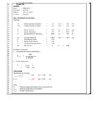
ASME B31.3 Minimum Allowable Wall Thickness Calculation (Design Conditions) Plant ID Plant Equipment Number: 1234 Equipment Name: Name Name Equipment Type: Pipe Date: 10th August 2014 Piping Classification Piping Spec & Grade: D1, SA-106 grade B Pipe Schedule: Sch 120 Nominal Thickness: 0.562 in Design Conditions: 1480 psig, -20⁰ to 100⁰ F Design Code: ASME B.31.3 P&ID Dwg: 5-007.032.PI.10-0012 Pressure design thickness (t) Reference: ASME B31.3, 304.1.2 (a)
t=
PD 2(SEW + PY)
where t = pressure design wall thickness, inches P = internal design gage pressure, psig D = outside diameter of pipe, inches S = stress value for material from Table A-1, ASME B.31.3 E = quality factor from table A-1A or A-1B, ASME B.31.3 W = weld joint strength reduction factor Y = coefficient from Table 304.1.1, valid for t < D/6, ASME B.31.3 P= D= S= E= W= Y=
1480 psi 6.625 in 20000 psi 1 1 in 0.4
t=
0.238 in
Minimum allowable wall thickness (tm)
tm = t + c where tm = pressure design wall thickness + ca, inches c = corrosion allowance t= ca =
0.238 in
tm =
0.288 in
0.05 in
ckness Calculation (Design Conditions)
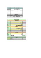
ASME B31.3 Minimum Allowable Wall Thickness Calculation (Operating Conditions) Plant ID Plant Equipment Number: 1234 Equipment Name: Name Name Equipment Type: Pipe Date: 10th August 2014 Piping Classification Piping Spec & Grade: D1, SA-106 grade B Pipe Schedule: Sch 120 Nominal Thickness: 0.562 in Operating Conditions:1480 psig, -20⁰ to 100⁰ F Design Code: ASME B.31.3 P&ID Dwg: 5-007.032.PI.10-0012 Pressure design thickness (t) for MAOP Reference: ASME B31.3, 304.1.2 (a)
t=
PoD 2(SEW + PY)
where t = pressure design wall thickness, inches Po = maximum allowable operating pressure (MAOP), psig D = outside diameter of pipe, inches S = stress value for material from Table A-1, ASME B.31.3 E = quality factor from table A-1A or A-1B, ASME B.31.3 W = weld joint strength reduction factor Y = coefficient from Table 304.1.1, valid for t < D/6, ASME B.31.3 P= D= S= E= W= Y=
300 psi 6.625 in 20000 psi 1 1 in 0.4
t=
0.049 in
Minimum allowable wall thickness ™ for MAOP
Composite Clock Spring Requirment
tm = t + c
Min 20% of nominal wall thickness remaining
where tm = pressure design wall thickness + ca, inches
At least 0.12 inches wall thickness remaining Remaining wall thickness above tn for MAOP
c = corrosion allowance t= ca =
0.049 in
tm =
0.099 in
0.05 in
Percentage wall thickness re T-nominal T-actual: % T-Remaining:
ckness Calculation (Operating Conditions)
Composite Clock Spring Requirments: Min 20% of nominal wall thickness remaining At least 0.12 inches wall thickness remaining Remaining wall thickness above tn for MAOP
Percentage wall thickness remaining 0.562 in in 0%
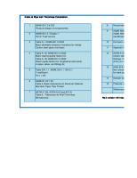
ASME B31.3-2010, Table A-1A Basic Casting Quality Factors, E c These quality factors are determined in accordance with para. 302.3.3(b). See also para. 302.3.3(c) and Table 302.3.3C for increased quality factors applicable in special cases. Specifications are ASTM. Spec. No.
Description
Ec [Note (2)]
Notes
Iron A 47 A 48 A 126 A 197 A 278 A 395 A 571
Malleable iron castings Gray iron castings Gray iron castings Cupola malleable iron castings Gray iron castings Ductile and ferritic ductile iron castings Austenitic ductile iron castings
1.00 1.00 1.00 1.00 1.00 0.80 0.80
(9) (9) (9) (9) (9) (9), (40) (9), (40)
Carbon Steel A 216 A 352
Carbon steel castings Ferritic steel castings
0.80 0.80
(9), (40) (9), (40)
Low and Intermediate Alloy Steel A217 Martensitic stainless and alloy castings A 352 Ferritic steel castings A 426 Centrifugally cast pipe
0.80 0.80 1.00
(9), (40) (9), (40) (10)
Stainless Steel A 351 A 451 A 487
0.80 0.90 0.80
(9), (40) (10), (40) (9), (40)
Copper and Copper Alloy B 61 Steam bronze castings B 62 Composition bronze castings B 148 Al–bronze and Si–Al–bronze castings B 584 Copper alloy castings
0.80 0.80 0.80 0.80
(9), (9), (9), (9),
Nickel and Nickel Alloy A 494 Nickel and nickel alloy castings
0.80
(9), (40)
Aluminum Alloy B 26, Temper F Aluminum alloy castings B 26, Temper T6, T71 Aluminum alloy castings
1.00 0.80
(9), (10) (9), (40)
Austenitic steel castings Centrifugally cast pipe Steel castings
(40) (40) (40) (40)
Table 304.1.1 Values of Coefficient Y for t < D/6 Temperature, °C (°F)
Materials Ferritic steels Austenitic steels Other ductile metals Cast iron
≤ 482 (900 & lower) 510 (950) 538 (1000) 566 (1050) 593 (1100) 0.4 0.4 0.4 0…
0.5 0.4 0.4
0.7 0.4 0.4 …
0.7 0.4 0.4 …
0.7 0.5 0.4 …
≥ 621 (1150 & Up) 0.7 0.7 0.4 …