![BW 120-4 English Service Training [PDF]](https://pdfs.asia/img/200x200/bw-120-4-english-service-training.jpg)
13 0 5 MB
Service Training
BW 100 AD/AC Series 4 BW 120 AD/AC Series 4 P/N 008 099 86
STATUS: 03/2004
Service Training Table of contents Foreword List of additional documentation General Maintenance
A1 A2 A3 A4
List of components
B1
Kubota diesel engine View of engine Pump installation on diesel engine View of diesel engine, flywheel side Tests and adjustments Adjusting the valve clearance Trouble Shooting
C1 C2 C3 C4 C5 C6 C8
Travel system Travel pump Travel pump control Charge pressure relief valve High pressure relief valves Drum drive motor Wheel drive motors on AC-machines Trouble shooting travel system Insufficient travel power The machine moves with the travel lever in “Neutral”
D1 D3 D7 D9 D 10 D 12 D 16 D 17 D 28 D 30
Vibration Vibration pump Vibration control valve Vibration motor Trouble shooting vibration
E1 E3 E4 E5 E6
Steering Steering valve Trouble shooting steering
F1 F3 F5
Electric circuit diagrams Table of contents Function groups Reference lines, frames Potential cross references Relay cross references List of components Electric system
G1 G1 G2 G3 G4 G5 G5 G6
________________________________________________________________________________________ BW 100/120 AD-3 1 BW 100/120 AC-3
Service Training Foreword In 2004 the tandem vibratory rollers of product range BW 100 AD/AC4 and BW 120 AD/AC4 were launched in the market for the first time. They are a further development of the old BW 100/120AD/AC of generation 3, which already were a great sales success. The contents of this training shall enable the service engineer to perform adjustments and trouble shooting as well as all necessary repair work in a professional manner. The owner of the machine should recognize that the service engineer is fully familiar with the machine. He should realize that the service engineer applies the correct measures to detect a possible fault on a machine and that all repair measures are performed with skill and knowledge. Persons participating on this training course should be confident when having to work on this machine.
Documentation For the BOMAG machines described in this training manual the following documentation is additionally available: Attention! The currently valid part numbers for the documents can be taken from the Doclist or the Customer Service page in the BOMAG Intranet or Extranet (BOMAG Secured Area) in accordance with the serial number of the machine. 1. 2. 3. 4. 5. 6.
Operating and maintenance instructions Spare parts catalogue Wiring diagram* Hydraulic diagram* Repair instructions Service Information
* The document versions valid at the date of printing are part of this training manual.
________________________________________________________________________________________ BW 100/120 AD-4 A1 BW 100/120 AC-4
Service Training General Machines of product range BW 100/120 AD/AC-4 are tandem vibratory rollers or combination rollers for compaction work in road construction. They are most suitable for the compaction of bituminous materials as well as light compaction tasks in earthwork. Compaction is achieved by the vibration of both drums or the vibration of the drum and the static load of the rubber tires. The power output from the water cooled Kubota diesel engine is transferred to drums or wheels (travel and vibration systems) and to the steering via the hydrostatic drive systems of the machine. This type of power transmission ensures lowest possible efficiency losses. Both drums of the BW 100/120 AD-4 are fitted with both travel motors as well as vibration motors. The motors for the respective drive systems are always arranged on one side of the machine. Since it is beneficial for many applications (e.g. when laying asphalt layers) to work with one vibrating and one static drum, the machine is equipped with a vibration shut-off valve for the rear drum. On machines of type BW 100/120 AC-4 the wheel set is driven by two travel motors. This roller combines the high compaction power of a vibration drum with the excellent surface sealing effect of rubber tires in one machine. This machine obviously achieves considerable savings in costs when compared with a pure vibratory or pneumatic tired roller. The standard equipment of the machine includes a gravity sprinkler system. A pressure sprinkler system is optionally available on request. In connection with the scrapers the water sprinkler system avoids picking up of material by the drums. On the AC-machines a pressure sprinkler system prevents sticking of dirt and bitumen to the rubber tires. For this purpose the tires are sprayed with emulsion. Front and rear frames of the machine are joined by an oscillating articulated joint. The amply dimensioned oscillation angle makes sure that the drums always have ground contact over the entire width. Both travel motors are fitted with integrated brakes working as parking brakes. Depending on the position of the brake solenoid valve these brakes are released by charge pressure when starting the engine and applied when shutting the engine down.
________________________________________________________________________________________ BW 100/120 AD-4 A2 BW 100/120 AC-4
Service Training Maintenance The tandem/combination rollers of series BW 100/120 AD/AC-4 are high performance machines for the extremely difficult use in asphalt compaction and earth work. To be able to meet these demands the machine must always be ready to be loaded up to its limits. Apart from that, all safety installations must always be fully functional when working under the partly very dangerous conditions on a construction site. Thorough maintenance of the machine is therefore mandatory. This not only guarantees a remarkably higher functional safety, but also prolongs the lifetime of the machine and of important components. The time required for thorough maintenance is only minor when being compared with the malfunctions and faults that may occur if these instructions are not observed. The maintenance intervals are given in operating hours. It is quite obvious that with each maintenance interval all the work for shorter preceding intervals must also be performed. During the 2000 hour interval you must also perform the maintenance work for the 500 and 1000 hour intervals. It should also be clear, that with the 2500 hours interval only the work for the 10 and 500 hour intervals must be performed. For maintenance work you must only use the fuels and lubricants mentioned in the table of fuels and lubricants (oils, fuels, grease etc.).
________________________________________________________________________________________ BW 100/120 AD-4 A3 BW 100/120 AC-4
Service Training List of components BW 100/120 AD/AC-4 Engine Manufacturer
Kubota
Type
D 1703 MDI
Cooling
Water
Working cycles
4
Number of cylinders
3
Power DIN 6271 IFN/SAE at 2700 rpm
kW
25,2
Fixed engine speed Stage 1
rpm
2250
Fixed engine speed Stage 2
rpm
2700
Valve clearance I/E
mm
0,20/0,20
Travel pump Manufacturer
Hydromatik
Type
A10 VG 28
System
Axial piston
Displacement
cm³/rev.
28
High pressure limitation
bar
380
Charge pressure
bar
24
Speed
rpm
2700
Max. flow capacity
l/min
73
________________________________________________________________________________________ BW 100/120 AD Series 4 B1 BW 100/120 AC Series 4
Service Training BW 100/120 AD/AC-4 Travel motor (drums) Manufacturer
Poclain
Type
MK 04
Number
2
System
Radial piston motor
Displacement
cm³/rev.
Brake
408 yes BW 100/120 AC-4
Travel motor (wheels) Manufacturer
Poclain
Type
MSE 02
Number
2
System
Radial piston motor
Displacement
cm³/rev.
Brake
255 yes BW 100/120 AD/AC-4
Vibration pump Manufacturer
Bosch
Type
HYZ 11
System
Gear
Displacement
cm³/rev.
11
Starting pressure
bar
210
Operating pressure
bar
100 +/-60 bar (soil dependent)
________________________________________________________________________________________ BW 100/120 AD Series 4 B2 BW 100/120 AC Series 4
Service Training Vibration motor Manufacturer
Bosch
Type
HYZ 8
System
Gear
Displacement
cm³/rev.
8
Frequency stage 1
Hz
55
Frequency stage 2
Hz
70
Amplitude
mm
0.5
Steering pump Manufacturer
Bosch
Type
HYZ 8
System
Gear
Displacement
cm³/rev.
8
max. steering pressure
bar
140 +/-30 bar
Steering valve Manufacturer
Danfoss
Type
OSPC 80 ON
System
Rotary valve
________________________________________________________________________________________ BW 100/120 AD Series 4 B3 BW 100/120 AC Series 4
Service Training Kubota diesel engine 1703 MDI The tandem vibratory rollers of series BW 100/120 AD/AC-4 are powered by a water cooled 3-cylinder Kubota diesel engine type 1703 MDI. The engine is an upright water-cooled four-stroke diesel engine.
Cross-section of diesel engine
________________________________________________________________________________________ BW 100/120 AD Series 4 C1 BW 100/120 AC Series 4
Service Training View of engine:
4
3
2
1
Pos. 1 Pos. 2 Pos. 3 Pos. 4
Engine temperature switch Connection glow plug Oil dipstick Injection nozzles
________________________________________________________________________________________ BW 100/120 AD Series 4 C2 BW 100/120 AC Series 4
Service Training Pump installation on diesel engine
3
1
2
Pos. 1 Pos. 2 Pos. 3
Charge pump Vibration pump Oil pressure switch
0.6 bar
________________________________________________________________________________________ BW 100/120 AD Series 4 C3 BW 100/120 AC Series 4
Service Training View of diesel engine, flywheel side
3
1
2
4
Pos. 1 Pos. 2 Pos. 3 Pos. 4
Travel pump Pressure test port A high pressure forward Pressure test port B high pressure reverse High pressure relief valves
380 bar
________________________________________________________________________________________ BW 100/120 AD Series 4 C4 BW 100/120 AC Series 4
Service Training Tests and adjustments Measuring the compression
Fig. 5: Compression pressure: 1. Run the engine warm and shut it down. Disassemble the nozzle holders. 2. Install the diesel engine compression tester to the nozzle holder opening. 3. Make sure that the throttle lever is in top position (no injection) and start the engine with the starter motor. 4. Read the max. pressure. Repeat the measurement at least two times. 5. If the measurement is below the permissible limit value check cylinder, piston, valve and cylinder head.
Adjustment values: Compression pressure
Factory settings 29.4 -32.4 bar Permissible limit value min. 23.5 bar
________________________________________________________________________________________ BW 100/120 AD Series 4 C5 BW 100/120 AC Series 4
Service Training Checking the valve clearance
IMPORTANT: The valve clearance must only be checked and adjusted when the engine is cold. The cylinders are counted from the flywheel end, i.e. cylinder 1 is on the flywheel side. 1. Remove the cylinder head cover. 2. Align the mark „1TC“ on the flywheel and the notched part (1) on the plate so that piston no. 1 is in compression stroke or overlaps top dead centre (TDC). 3. Measure the valve clearance marked "1" with a feeler gauge. 4. Correct the clearance by the setscrew if it is not within the limits of the specified factory data. Valve clearance (cold)
Factory settings
0,20 mm
(The values apply for intake and exhaust valves) ________________________________________________________________________________________ BW 100/120 AD Series 4 C6 BW 100/120 AC Series 4
Service Training Please note that the TC-mark is only valid for cylinder 1. There is no mark for the other cylinder. Cylinder 1 is in compression stroke when the TC-mark is visible in the window (2) Now turn the flywheel further, until the other valves overlap top dead centre and adjust the valve clearance accordingly. Note: • The "TC"-mark on the flywheel applies only for cylinder no. 1. The other cylinder has no "TC"-mark. • When the „TC“-mark is aligned with the punched mark on the rear disc, piston no. 1 is in top dead centre position. Now turn the flywheel bz 15° clockwise or anticlockwise to check whether the pistons are in TDC-position (compression position). (The piston is in TDC when intake and exhaust valves do not move. When both valves are moving, the piston is in overlapping position.) • Finally turn the flywheel by 360 ° to ensure that „TC“-mark and punched mark match exactly. All valve clearances must be set to the nominal value. • Turn the flywheel two to three times in anti-clockwise direction to check the valve clearance. • After adjusting the valve clearance retighten the locking nut of the setscrew.
________________________________________________________________________________________ BW 100/120 AD Series 4 C7 BW 100/120 AC Series 4
Service Training Troble Shooting Fault
Possible cause
Remedy
Engine does not start
• No fuel • Air in the fuel system • Water in the fuel system
Fill in fuel Bleed Replace fuel and clean or replace the fuel system
• Fuel line clogged • Fuel filter clogged • Too high viscosity of fuel or engine oil at low temperatures • Fuel with low Ceten-number
Clean Replace Use specified fuel
• Fuel loss caused by loose locking but on injection line • Incorrect adjustment of injection • Fuel camshaft worn • Injection nozzle clogged • Malfunction of fuel lift pump • Crankshaft, camshaft, piston or bearings seized • Loss of compression on a cylinder
Tighten nuts
• Incorrect valve seat alignment, valve spring broken, valve seized • Insufficient valve control • Piston rings worn • Excessive valve clearance • Battery discharged Starter does not work
• Malfunction of starter • Malfunction of ignition switch • Wiring has come loose
Use specified fuel
Adjust Replace Clean Repair or replace Repair or replace Replace cylinder head gasket, tighten cylinder head screws, glow plug and nozzle holder Repair or replace Adjust Replace Adjust Charge Repair or replace Repair or replace Connect
________________________________________________________________________________________ BW 100/120 AD Series 4 C8 BW 100/120 AC Series 4
Service Training Fault
Possible cause
Remedy
Engine does not turn regularly
• Fuel filter clogged or soiled • Air filter clogged • Fuel loss caused by loose locking but on injection line • Faulty function of injection pump • Incorrect injection valve opening pressure • Injection nozzle sticking or clogged • Fuel overflow line clogged • Malfunction of regulator • Too high engine oil level • Piston ring worn or sticking • Incorrect injection setting • Insufficient compression • Cylinder head gasket defective • Overload • Poor fuel quality • Fuel filter clogged • Air filter clogged • Incorrect injection setting • Moving engine parts possibly seized • Uneven fuel injection
Replace Clean or replace Tighten nuts
White or blue exhaust gas
Black or dark grey exhaust fumes
Insufficient power
• • • •
Repair or replace Adjust Repair or replace Clean Repair Correct the oil level Replace Adjust Check compression pressure Repair Reduce the load Use specified fuel Replace Clean or replace Adjust Repair or replace Repair or replace the injection pump Repair or replace the nozzle Replace cylinder head gasket, tighten cylinder head screws, glow plug and nozzle holder Replace Replace piston Replace Replace
• Cylinder head gasket defective • Cracks in crankcase or cylinder head
Replace pump elements or pump Replace Replace
• Insufficient nozzle injection • Loss of compression
Excessive lubrication oil consumption
Fuel mixed with lubrication oil Water mixed with lubrication oil
Oil scraper ring worn or sticking Piston ring groove worn Valve stem and guide worn Crankshaft bearing and crank journal bearing worn • Injection pump plunger worn
Lubrication oil in coolant • Cylinder head gasket defective
Replace
________________________________________________________________________________________ BW 100/120 AD Series 4 C9 BW 100/120 AC Series 4
Service Training Fault
Possible cause
Remedy
Too low oil pressure
• • • • •
Top up Clean Replace Clean Replace
Excessive oil pressure Engine overheating
Rapid discharging of battery
• • • • • • • • • • • • • • • • • • •
Engine oil level too low Oil strainer clogged Oil filter cartridge clogged Pressure relief valve clogged with dust Pressure relief valve spring fatigued or broken Excessive clearance of crankshaft bearing Excessive clearance of Rocker arm shaft Oil passage clogged Different type of oil Oil pump defective Different type of oil Pressure relief valve defective Engine oil level too low Fan drive belt broken or not correctly tightened Coolant level too low Radiator and cooling fins clogged by dust Radiator internally corroded Coolant line corroded Radiator cap defective Water pipe damaged Thermostat defective Water pump defective Overload Battery fluid level too low
• Fan drive belt slipping • • • •
Wiring has come loose Regulator defective Generator defective Battery defective
Replace Replace Clean Use specified oil quality Repair or replace Use specified oil quality Replace Top up Replace or adjust Top up Clean Clean or replace Clean or replace Replace Replace Replace Replace Reduce the load Top up distilled water and recharge Adjust the tension or replace the belt Connect Replace Replace Replace
________________________________________________________________________________________ BW 100/120 AD Series 4 C 10 BW 100/120 AC Series 4
Service Training Engine solenoid: The machine is equipped with a solenoid which works according to the principle „ENERGIZED TO RUN“. This solenoid has the benefit that the engine will be immediately shut down in case of a fault in the electric system. A disadvantage is the quite costly design of the solenoid with two coils. Nominal currents of windings: Pickup winding (PW)
51 A
Holding winding (HW)
0.7 A
Solenoid
Fig. 14: Function of the engine solenoid: The pickup winding (PW) is directly triggered via potential 30. Once the engine has started and oil pressure is available the voltage to the pickup winding is interrupted and voltage is only applied to the holding winding.
________________________________________________________________________________________ BW 100/120 AD Series 4 C 11 BW 100/120 AC Series 4
Service Training Travel system: On the machines described in this training manual the travel system consists of a closed hydraulic circuit. It mainly consists of the travel pump with the integrated safety elements, two travel motors, the hydraulic oil filter and the hydraulic oil cooler.
Charge pressure from brake valve
Charge pressure from brake valve
High pressure test ports MA and MB
Charge pressure after hydraulic filter
Leak oil port to tank
The installation of a hydraulic pump with variable displacement into a closed hydraulic circuit is a perfect solution for a hydrostatic travel system, because with this design the travel direction can be reversed without any problems. The travel pump is flanged to the flywheel side of the diesel engine. It is directly driven by the engine with constant speed. The tandem gear pump driven by the auxiliary output of the diesel engine consists of a steering/charge pump and a vibration pump. The return flow from the steering valve is fed through the charge oil port into the travel pump. ________________________________________________________________________________________ BW 100/120 AD Series 4 D1 BW 100/120 AC Series 4
Service Training Besides its function of supplying the closed circuit with cool and filtered oil as replacement for leakage and flushing losses, the oil from the charge circuit is also used to release the travel motor integrated brakes: All safety and control elements needed for the operation in a closed hydraulic circuit are integrated in the travel pump. These are: High pressure relief valves (380 bar) with integrated boost check valves Charge pressure relief valve (24 bar) Servo control The travel motors (on AD-machines) are hydraulically connected parallel to each other. On AC-machines all three motors are arranged parallel to each other.
________________________________________________________________________________________ BW 100/120 AD Series 4 D2 BW 100/120 AC Series 4
Service Training Travel pump The travel pump is a swash plate operated axial piston pump with variable displacement from Bosch Rexroth-Hydromatik, type A 10 VG 28.
3
5
2
380 bar
4
1
5
380 bar
Leak oil to tank
To the travel motors
24 bar
Charge pressure
Hydraulic diagram for travel pump 1
Pump drive
2
Control piston
3
4/3-way servo valve
4
Charge pressure relief valve
5
High pressure relief valves
The pump is fitted with all control and safety elements needed for operation in a closed hydraulic circuit. These are:
________________________________________________________________________________________ BW 100/120 AD Series 4 D3 BW 100/120 AC Series 4
Service Training Servo control High pressure relief valves with integrated boost check valves Charge pressure relief valve
The travel pump unit is directly driven by the flywheel side of the engine via an elastic coupling. The pump speed is therefore identical with the engine speed.
6
7
8 5
4
2
1 3
Travel pump, cross-section 1
Drive shaft
2
Swashing cradle with swashing lever
3
Cylinder block
4
Working pistons
5
Control piston
6
Control unit with feedback lever
7
Slipper pad
8
Valve plate
________________________________________________________________________________________ BW 100/120 AD Series 4 D4 BW 100/120 AC Series 4
Service Training Pilot pressure is used to operate the pump out of neutral position to the desired pumping direction (direction of oil flow). A manually operated 4/3-way valve directs the pilot oil flow (from the charge circuit) to the corresponding control piston side in the servo control. The 4/3-way valve is controlled by the travel lever and the travel cable. In neutral position both control chambers are loaded with case pressure. When opening the 4/3-way valve pilot oil (from the charge circuit) is directed to one of the control piston sides and moves the control piston to the corresponding direction. The swashing lever between the control piston and the swash plate transfers the control piston movement to the swash plate. The needle bearing mounted swash plate swivels to the chosen direction. This causes the axial movement of the pistons inside the cylinder block. The axial movement draws oil into the pump and presses it to the travel motors. All working pistons are drilled through their entire length. Pressure fluid flows through these bores into the areas between the slipper pads and the surface of the swash plate. This forms a hydraulically balanced field, on which the slipper pads can slide without any metal to metal contact between swash plate and slipper pads. The feedback lever on the control piston detects when the swash plate has reached a position that corresponds with the displacement of the travel lever. This feedback lever controls a pilot oil portioning valve which interrupts the pilot oil flow to the control chambers when the swashing angle corresponds with the position of the travel lever. Swashing angle and displacement of the working pistons (oil flow rate) remain constant, until a new control command requires a different swashing angle. When changing the swashing angle through the neutral position to the opposite side, the flow direction of the oil and the sense of rotation of the travel motors will change. The spherical valve plate centres cylinder block, which is mounted on the splines of the drive shaft. This avoids the appearance of undesired transverse forces. The complete drive consisting of valve plate cylinder block with working pistons and swash plate is held together and preloaded by Belleville springs. This immediately eliminates any appearing wear, increases the efficiency of the pump and prolongs the lifetime considerably. When controlling the travel pump pressure will build up in the line between pump outlet and motor inlet. This pressure depends on the load acting on the travel motors. This pressure keeps the boost check valve inside the high pressure relief valve for this particular side of the closed hydraulic circuit closed. Cool and filtered oil can now only enter into the closed circuit on the opposite side (low pressure side). The high pressure relief valve limits possibly occurring extreme pressure peaks to the adjusted value. If one of these valves responds, hydraulic oil will flow out of the high pressure side and enter the low pressure side through the corresponding boost check valve.
________________________________________________________________________________________ BW 100/120 AD Series 4 D5 BW 100/120 AC Series 4
Service Training Control The servo control of the pump is an integral part of the pump housing and consists mainly of: the manually controlled 4/3-way valve (1) the control piston (2) the feedback lever (3) the swashing lever with the swashing cradle (see Fig. 3).
________________________________________________________________________________________ BW 100/120 AD Series 4 D6 BW 100/120 AC Series 4
Service Training Travel pump control When actuating the travel lever the 4/3-way valve moves out of neutral position to the desired direction and guides the pilot oil flow through the pilot oil portioning valve to the corresponding control piston side. The control piston moves to the corresponding direction and operates the swash plate via the swashing lever accordingly. The feedback lever, which is mounted with its ball head in the pump control shaft, follows the control piston and interrupts the pilot oil flow when the control piston has reached a position corresponding with the displacement of the travel lever. The pump can now deliver oil to the travel motors. The oil from the opposite control chamber flows through the 4/3-way valve as leak oil into the pump housing. The supply bores to both control chamber sides are fitted with nozzles (swashing time nozzles). These nozzles restrict the pilot oil flow and enable a very sensitive control of the pump.
Control in neutral position
________________________________________________________________________________________ BW 100/120 AD Series 4 D7 BW 100/120 AC Series 4
Service Training The feedback lever controls the pilot oil portioning valve so that the swashing angle remains unchanged, until the introduction of a new control command.
Control actuated When the 4/3-way valve is in neutral position, the pressure values in both control chambers are identical (case pressure = max. 3 bar).
________________________________________________________________________________________ BW 100/120 AD Series 4 D8 BW 100/120 AC Series 4
Service Training Charge pressure relief valve The charge pressure relief valve belongs to the group of safety elements in a closed hydraulic circuit. This valve limits the pressure in the charge circuit to the adjusted value.
Charge pressure relief valve The charge circuit is needed for the compensation of leak oil and flushing quantities in the closed hydraulic circuit. Charge oil is also required to control the pumps and to release the parking brake. Since feeding of cool and filtered oil is only possible on the low pressure side of the closed circuit, the pressure in the low pressure side is identical with charge pressure. If the travel pump is in neutral position, both boost check valves can open and let in oil from the charge circuit. In this case the pressure in both sides of the closed circuit is identical with charge pressure.
________________________________________________________________________________________ BW 100/120 AD Series 4 D9 BW 100/120 AC Series 4
Service Training High pressure relief valves High pressure relief valves are safety elements, which are needed in every hydraulic circuit. These valves limit the pressure in the hydraulic circuit to the value determined by the adjustment spring.
Hydraulic diagram 1
Travel pump
2
Control piston (actuated)
3
4/3-way valve (actuated)
4
High pressure relief valves, fixed adjustment (380 bar)
________________________________________________________________________________________ BW 100/120 AD Series 4 D 10 BW 100/120 AC Series 4
Service Training High pressure relief valves 1
2
1
1
High pressure relief valves
2
Charge pressure relief valve
The high pressure relief valves in both sides of the hydraulic circuit protect the hydraulic system, the diesel engine and all other machine components against overloads. The boost check valves are integrated in the high pressure relief valves. These valves open to the low pressure side and let cool and filtered oil flow from the charge oil circuit into the closed hydraulic circuit, in order to compensate leaks and flushing quantities. High pressure relief valve 380 bar
________________________________________________________________________________________ BW 100/120 AD Series 4 D 11 BW 100/120 AC Series 4
Service Training Drum drive motor: Poclain travel motor type MK04 Both drums are driven by Poclain travel motors type MK04. These are radial piston motors. These drive motors consist of the outer housing, the flat distributor, the cylinder block with the working pistons, the output shaft and the brake. The brake is designed as a Hirthtoothing. The housing consists of Ø Ø Ø Ø
bearing section (bearings for output shaft) torque module (cam race) oil distributor and Hirth brake
The function of the radial piston motor is described hereunder. The piston positions mentioned in the description are shown in the corresponding illustration.
The movement of a piston along the cam race must be examined during various phases of the rotation.
________________________________________________________________________________________ BW 100/120 AD Series 4 D 12 BW 100/120 AC Series 4
Service Training Piston position 1: Ø
The oil enters into the oil distributor under pressure, flows through the distributor and presses against the piston. This is the start of a rotation. Due to the pressure on the back of the piston the roller will move along the cam, thereby causing a rotary movement of the cylinder block.
Piston position 2:
Ø
At this point the oil flow to the piston has reached its largest cross section. The piston continues its travel along the cam race towards the valley between two cams. The opening cross section decreases with continuing rotary movement.
Piston position 3: Ø
Once the piston has reached the deepest point the oil flow to the piston is cut off. The piston is no longer driven. It has reached its dead centre. Another piston must now be driven to move the previous piston out of dead centre position.
Piston position 4: Ø
By driving other pistons the previous piston is moved out of dead centre position. The oil behind the piston is connected with the low pressure side and the retracting piston presses it back to the pump.
Piston position 5: Ø
The oil supply back to the pump comes close to an end, the connecting bore between cylinder and low pressure side closes slowly. The piston will now reach its second dead centre position. This point is the start of a new working cycle.
Reversing the oil flow reverses also the rotation of the motor.
________________________________________________________________________________________ BW 100/120 AD Series 4 D 13 BW 100/120 AC Series 4
Service Training Brake actuation MK04 motor (drum drive motor) The travel system is equipped with a Hirth-type brake in the travel motors. This brake serves as parking brake to park the machine. (to secure the machine when the engine is running or to park the machine with the engine shut down) and as emergency brake. The brake control is accomplished via a 3/2 way valve which is located at the front in the engine compartment. If the solenoid valve is supplied with electric current when the engine is started, the valve will switch over and guide charge pressure into the brake housings. This releases the brakes. If the solenoid valve is de-energized while the engine is running (e.g. when actuating the emergency stop switch), the oil pressure in the brake housings is relieved to the tank and the brakes will close.
Hirth gearing
________________________________________________________________________________________ BW 100/120 AD Series 4 D 14 BW 100/120 AC Series 4
Service Training During travel operation the machine is braked by the closed hydraulic circuit. When moving the travel lever to neutral position the supply from the pump is interrupted. The machine will stop. However, both travel motors are additionally fitted with brakes. These brakes work only as parking brakes. The brakes are automatically relieved by the charge pressure building up when starting the engine. Should the charge pressure drop considerably (failure or shutdown of the engine, damage in the hydraulic system), the brakes close automatically. When shifting the travel lever to neutral position the brake closes after a short while. The brake closes also when the seat contact switch is open. The brakes can be relieved mechanically with screws. The mechanical releasing of the brakes works as follows:
-
Unscrew the 2 plugs (191) Press the screws (192) against the springs (193) Tighten both screws (192) alternately and in steps until they bottom (approx. 2 revolutions) (max. 35 Nm)
To close the brake, proceed in reverse order.
________________________________________________________________________________________ BW 100/120 AD Series 4 D 15 BW 100/120 AC Series 4
Service Training Wheel drive motors on AC-machines The rubber tires of the BW 100/120 AC-4 are driven by two radial piston motors Poclain MSE 02 which are joined parallel to each other and also parallel to the drum drive motor. The function of the motor is identical with the previously described Poclain motor MK04. However, the main difference is the design of the integrated brake. The MSE02 is fitted with a multi-disc brake. This consists of inner and outer discs which run permanently in an oil bath. Since the brake is normally only applied in events of emergency, it is almost wear free. If needed, the brakes can be released with the help of a brake releasing device. For this purpose a ball valve is installed in the engine compartment. By operating this valve oil can be directly guided to the motors (drum as well as wheel drive motors). For this purpose the steering wheel must be slowly turned for approx. two turns in clockwise direction. In this case the steering wheel or Orbitrol has the effect of a pump and delivers oil to the brakes (to the drum as well as the wheel drive motors). The brakes are thereby is released.
________________________________________________________________________________________ BW 100/120 AD Series 4 D 16 BW 100/120 AC Series 4
Service Training Trouble shooting travel system Machine does not drive Checking the function of the brake valve > Switch the ignition on > Release the parking brake by shifting the travel lever out of neutral position > Measure the voltage supply on the solenoid valve Nominal value: 12 V If the voltage supply is not correct perform trouble shooting in the electric system. If the voltage supply is correct the current consumption of the brake valve must be checked next: > For this purpose the meter must be connected in line with the solenoid of the brake valve > Switch the ignition on Nominal value: max. 2.7 A If no current consumption can be detected, change the solenoid coil
Brake valve
Fig. 1
________________________________________________________________________________________ BW 100/120 AD Series 4 D 17 BW 100/120 AC Series 4
Service Training If the solenoid coil is o.k., check the solenoid valve. > Connect a 60 bar pressure gauge to the pressure test port > Start the engine and move the travel lever out of neutral. > Read the pressure gauges. Nominal value: approx. charge pressure 24 bar
Pressure test port M3
Fig. 2
________________________________________________________________________________________ BW 100/120 AD Series 4 D 18 BW 100/120 AC Series 4
Service Training If the charge pressure value is not reached check the brakes in the motors. > Connect a 600 bar pressure gauge to pressure test port (M1). > Close the brake (travel lever in neutral) > Start the engine > Turn the steering against an end stop and read the pressure gauge Nominal value approx.: 170 bar
Test port M1
Fig 3: If the steering pressure value is not reached replace the steering/charge pump.
________________________________________________________________________________________ BW 100/120 AD Series 4 D 19 BW 100/120 AC Series 4
Service Training If the steering pressure is correct check the charge pressure relief valve of the travel pump. > Unscrew the plug. > Take the valve insert out. > Check the valve visually. Replace the valve immediately if damaged.
Charge pressure relief valve
Fig 4:
________________________________________________________________________________________ BW 100/120 AD Series 4 D 20 BW 100/120 AC Series 4
Service Training If the valve is o.k., check the brakes. > Disconnect the brake hoses from front and rear travel motor, one after the other, and close them with plugs. > Perform a pressure test on the pressure test port (near hydraulic oil filter M 3) after each disconnection of a brake hose If the charge pressure value is not reached replace the corresponding motor.
Disconnect the brake line and close it with a plug (line in the back)
Fig 5:
________________________________________________________________________________________ BW 100/120 AD Series 4 D 21 BW 100/120 AC Series 4
Service Training If the charge pressure is correct check the high pressure of the travel pump. Attention! The following test must not exceed 5 seconds ! > Close high pressure ports A and B. > Connect 600 bar pressure gauges to the high pressure test ports > Run the engine in idle speed and actuate the travel pump quickly to both directions. > Read the pressure gauges. Nominal value: approx. 400 bar
Close the ports
Install 600 bar pressure gauges
Fig 6:
________________________________________________________________________________________ BW 100/120 AD Series 4 D 22 BW 100/120 AC Series 4
Service Training If the high pressure value is not reached replace the high pressure relief valves. If the problem still exists after replacing the high pressure relief valves, replace or repair the travel pump.
High pressure relief valves
Fig 7:
________________________________________________________________________________________ BW 100/120 AD Series 4 D 23 BW 100/120 AC Series 4
Service Training If the high pressure value is reached, the travel motors must be checked individually. > Reconnect the high pressure hoses from the front travel motor to the travel pump. > Repeat the pressure test If the high pressure value is not reached replace the front travel motor. If the high pressure value is reached replace the rear travel motor.
Connect hoses from front travel motor or close ports to rear travel motor
Connect 600 bar pressure gauges
Fig 8:
________________________________________________________________________________________ BW 100/120 AD Series 4 D 24 BW 100/120 AC Series 4
Service Training If the charge pressure is reached in the test described under Fig. 2, charge pressure must be checked together with high pressure. > Connect 600 bar pressure gauges to the pressure test ports MA and MB. (Travel pump) > Run the engine with max. speed > Block the drum or disconnect the cable from the brake valve. > Actuate the travel lever for a moment and read the pressure gauge Nominal value:
charge pressure approx. 22 to 24 bar high pressure approx. 380 bar
Connect 600 bar pressure gauges
Charge pressure test port M3
Fig 9: ________________________________________________________________________________________ BW 100/120 AD Series 4 D 25 BW 100/120 AC Series 4
Service Training If the charge pressure is reached check the control chamber pressure. > Connect pressure test ports to the control chambers (X1 and X2). > Connect a 60 bar pressure gauge to the pressure test ports > Block the drum or disconnect the cable from the brake valve. > Actuate the travel pump to full displacement and read the pressure gauge. Nominal value:
approx. 24 bar
If the control chamber pressure value is not reached replace or repair the travel pump.
Control chamber pressure test port
Fig 10:
________________________________________________________________________________________ BW 100/120 AD Series 4 D 26 BW 100/120 AC Series 4
Service Training If the control chamber pressure is reached and the high pressure value is correct, release the brakes in both travel motors mechanically > Check whether the machine is able to drive If the machine drives replace or repair the travel motor with the defective brake. Mechanical releasing of brake (AD-machines only) is accomplished as follows: - Unscrew the 2 plugs (191) - Press the screws (192) against the springs (193) - Tighten both screws (192) alternately and in steps until they bottom (approx. 2 revolutions) (max. 35 Nm)
Fig 11:
________________________________________________________________________________________ BW 100/120 AD Series 4 D 27 BW 100/120 AC Series 4
Service Training Insufficient travel power With this fault the engine speed must be checked first. Nominal value:
Stage 1 = 2250 rpm Stage 2 = 2700 rpm
If the nominal speeds are not reached perform trouble shooting on the engine.
If the speed values are correct check the travel control. > Detach the control cable > Shift the pump control lever forward and reverse and check whether the pump swashes to maximum displacement. > Check whether the travel cable is worn.
Detach the control cable
Fig 12:
________________________________________________________________________________________ BW 100/120 AD Series 4 D 28 BW 100/120 AC Series 4
Service Training If the end stops are not reached adjust the end stops. Adjust the end stops for the speed on the setscrews > Check the travel cable for wear.
End stop for travel speed in reverse
End stop for travel speed in forward
Fig 13:
________________________________________________________________________________________ BW 100/120 AD Series 4 D 29 BW 100/120 AC Series 4
Service Training The machine moves with the travel lever in “Neutral” With this fault the neutral position of the pump must be checked first. > Shift the travel lever to ”Neutral” position > Disconnect the travel cable from the pump Check, whether bores in ball socket and pump control lever are in line.
Detach the control cable
Fig 14:
________________________________________________________________________________________ BW 100/120 AD Series 4 D 30 BW 100/120 AC Series 4
Service Training If the bores are not in line adjust the travel cable. > Slacken the counter nut on the back stop. > Adjust the nuts until the travel cable corresponds with the neutral setting of the pump. > Tighten the counter nut again
Fig 15:
________________________________________________________________________________________ BW 100/120 AD Series 4 D 31 BW 100/120 AC Series 4
Service Training If the bores are in line check the mechanical neutral position. > Join both control chambers of the travel pump (X1 and X2) Note: The resulting condition of equilibrium must bring the machine to standstill. If the neutral position is reached by this measure replace or repair the servo control on the machine.
Connect ports X1 and X2 with a hose
Fig 16:
________________________________________________________________________________________ BW 100/120 AD Series 4 D 32 BW 100/120 AC Series 4
Service Training If the neutral position is not reached it is necessary to adjust the mechanical neutral position. > Connect 600 bar pressure gauges to MA and MB. > Block the drum or disconnect the cable from the brake valve. > Run the engine with max. speed. > Read the pressure gauges. > Adjust the mechanical 0-position until the pressure readings are identical on both sides If the neutral position is not reached, replace or repair the travel pump.
Setscrew underneath the servo control
Fig 17:
________________________________________________________________________________________ BW 100/120 AD Series 4 D 33 BW 100/120 AC Series 4
Service Training Vibration The vibration drive is an open hydraulic circuit and consists mainly of the vibration pump, the control valve and the vibration motors. Circuit diagram AD-machine
8 cm³
8 cm³
110+10 bar
210+10 bar
11 cm³
Fig. 20:
________________________________________________________________________________________ BW 100/120 AD Series 4 E1 BW 100/120 AC Series 4
Service Training The vibration pump is directly driven by the timing gear side of the diesel engine. Vibration pump and steering/charge pump are joined together to a tandem pump unit. The gear pump delivers the hydraulic oil out of the hydraulic oil tank to the vibration control valve. If the vibration is switched off the hydraulic oil flows directly back to the tank. When the vibration is switched on, the control valve directs the oil flow to the in line connected vibration motors (BW 100/120 AD-4), or to the vibration motor on the drum (BW 100/120 AC-4). The vibration motors (gear motors) drive the vibrator shafts in the drums with constant speed via Bowex couplings. The rotation of the exciter shafts with the attached eccentric masses generates the vibration of the drums, which are suspended in rubber elements. From the second vibration motor the oil flows back through the control valve block to the tank (open circuit). The standard equipment of the AD-machine includes a shut-off valve for the rear drum vibration. When operating a ball valve the oil flow is directly returned to the tank after the first motor (front drum) via the control valve block
________________________________________________________________________________________ BW 100/120 AD Series 4 E2 BW 100/120 AC Series 4
Service Training Vibration pump The vibration pump is a directly driven gear pump.
Fig 21: The drive gear is connected with the auxiliary drive of the diesel engine via a pinion. Drive gear and driven gear are positioned by a bearing plate in such a way, that the gears mesh with minimum clearance when rotating. The displacement chambers are created between the tooth flanks, the inside wall of the housing and the faces of the bearing plates. During operation of the pump the hydraulic oil is transported in these chambers from the suction side to the pressure side. This causes a vacuum in the suction line by which the hydraulic oil is drawn out of the tank. These tooth chambers convey the fluid to the pump outlet from where it is pressed to the consumer. To ensure a safe function of the pump the tooth chambers must be so tightly sealed that the hydraulic fluid can be transported from the suction side to the pressure side without any losses. Outer gear pumps are fitted with gap seals. In dependence on the operating pressure there will be losses from the pressure side to the suction side. An axial pressure field presses the bearing plate on the cover side against the front face of the gears, making sure that only a very little quantity of oil will leak from the pressure side to the suction side when the pressure increases. The pressure field is always under the actual system pressure. The vibration pump delivers the hydraulic oil from the tank to the vibration motors and from there back to the tank.
________________________________________________________________________________________ BW 100/120 AD Series 4 E3 BW 100/120 AC Series 4
Service Training Vibration control valve With the vibration control valve the vibration is electrically switched on and off. The valve consists of the solenoid operated valve piston, the pressure relief valve for the vibration circuit and the brake valve to brake the exciter shafts when switching the vibration off. When switching the vibration on the direct return flow to the hydraulic oil tank is interrupted and the hydraulic oil is guided to the vibration motors. The high pressure (starting pressure) in the vibration circuit generated by the resistance of the resting exciter shafts is limited to 210 bar by a pressure relief valve inside the control valve block. When operating the control valve the valve spool opens also a direct connection between the outlet of the second vibration motor and the oil tank. When switching the vibration off this direct connection is interrupted. The hydraulic oil, which is now displaced to the control valve by the still rotating vibration motors is applied to 110 bar pressure relief valve (brake valve). This valve brakes the rotation of the exciter shafts within the shortest possible time.
________________________________________________________________________________________ BW 100/120 AD Series 4 E4 BW 100/120 AC Series 4
Service Training Vibration motor On the machines of series BW 100/120 AD-4 and BW 100/120 AC-4 the exciter shafts inside the drums are directly driven by vibration motors. These vibration motors are gear motors which are directly connected with the exciter shafts via Bowex couplings. The design of these vibration motors is almost identical with the design of the vibration pump. A more detailed description of the design is therefore not required. On the BW 100/120 AD-4 the vibration motors are connected in series. The standard equipment of the machine includes a shut-off valve for the rear drum vibration. When operating a ball valve the oil flow is directly returned via the control valve block to the tank after the first motor.
________________________________________________________________________________________ BW 100/120 AD Series 4 E5 BW 100/120 AC Series 4
Service Training Trouble shooting vibration Vibration frequency too low If the specified exciter shaft speed is not reached, the engine speed must be checked first. Check the engine speed with a vibration reed frequency meter.
Nominal value:
2700 rpm (with throttle control in stage II)
If the nominal speed is not reached perform trouble shooting on the engine. Various instruments or methods may be used to check the engine speed. (e.g. vibration reed frequency meter, optical speedometer etc.)
________________________________________________________________________________________ BW 100/120 AD Series 4 E6 BW 100/120 AC Series 4
Service Training If the engine speed is correct, check the pressures in the vibration circuit. > Stand both drums on an elastic base (rubber tires). > Connect a 600 bar pressure gauge to vibration pressure test port. > Run the engine with full speed and switch the vibration on. Nominal value :
Starting pressure approx. 210 bar (for approx. 3 - 6 seconds) Operating pressure (one vibrating drum): approx. 60 bar Operating pressure (two vibrating drums): approx.: 100 bar
Test port
Fig 22:
________________________________________________________________________________________ BW 100/120 AD Series 4 E7 BW 100/120 AC Series 4
Service Training If the starting pressure is not reached check the control valve block. > Disconnect the high pressure hoses from the valve block (A and B). > Close ports A and B on the valve block. > Switch the vibration on. Nominal value :
approx. 210 bar
________________________________________________________________________________________ BW 100/120 AD Series 4 E8 BW 100/120 AC Series 4
Service Training If the pressure value is not reached subject the vibration pump to a high pressure check. > Install a 200 bar pressure relief valve with a 600 bar pressure gauge between vibration pump and vibration valve. > Start the engine and switch on the vibration Nominal value :
approx. 200 bar
If the pressure is reached replace the vibration valve block. If the pressure value is not reached replace the vibration pump.
________________________________________________________________________________________ BW 100/120 AD Series 4 E9 BW 100/120 AC Series 4
Service Training If the pressure is reached during the pressure test described in Fig. 5, check the leak oil rate of the vibration motors. For this purpose stand the machine on rubber tires. > Disconnect the leak oil line and hold it into a measuring vessel. > Switch the vibration on. Nominal value: max. 1.0 l/min Replace the motor with too high leak oil rate.
Fig 23: If the starting pressure is reached, but the operating pressure is too low, you must also check the leak oil rate of the vibration motors.
________________________________________________________________________________________ BW 100/120 AD Series 4 E 10 BW 100/120 AC Series 4
Service Training If the operating pressure is too high, the bearings for both vibrator shafts must be checked. > Check end float and moveability of the exciter shafts (front and rear). Nominal values:
min 0.5 mm max. 2.00 mm
Fig 24:
________________________________________________________________________________________ BW 100/120 AD Series 4 E 11 BW 100/120 AC Series 4
Service Training No vibration If the vibration does not work at all you should first check the voltage supply for the vibration control valve. > Switch the vibration on and check whether voltage is applied to the plug. Nominal value:
12 Volt
If no voltage is applied, perform trouble shooting in the electric system.
Vibration solenoid valve
Fig 25: If voltage is applied check the magnetic coil of the control valve. > Measure the current consumption with a meter. (For this purpose the meter must be connected in line with the magnet) Nominal value :
approx. 3.5 A
If the current consumption is not correct replace the magnetic coil. If the current consumption is correct continue trouble shooting with Fig. 22.
________________________________________________________________________________________ BW 100/120 AD Series 4 E 12 BW 100/120 AC Series 4
Service Training Steering The steering system is an open hydraulic circuit and consists mainly of the steering/charge pump, the steering valve, the steering cylinder and the connecting pressure resistant hoses.
________________________________________________________________________________________ BW 100/120 AD Series 4 F1 BW 100/120 AC Series 4
Service Training The steering pump delivers the hydraulic oil from the tank to the steering valve and the connected steering cylinder. When the steering is not operated the complete oil flow is guided through the fine filter to the charge ports on the travel pump and further via the cooler to the tank. When turning the steering wheel the distributor valve guides the oil flow to the piston or piston rod side of the steering cylinder. A measuring pump in the steering unit measures the exact oil quantity corresponding to the turning angle of the steering wheel and delivers this oil to the steering cylinder. The steering cylinder extends or retracts and articulates the machine. The steering unit is fitted with an integrated pressure relief valve. This valve limits the steering pressure to 140 bar. Since the hydraulic oil flowing out of the steering system is used as charge oil for the closed travel circuit, the charge pressure value must be added. When testing the pressure a value of 160 bar would therefore be measured.
________________________________________________________________________________________ BW 100/120 AD Series 4 F2 BW 100/120 AC Series 4
Service Training Steering valve The steering valve block consists mainly of distributor valve, measuring pump, steering pressure relief valve and the shock valves. When turning the steering wheel the oil flow from the pump is directed through the distributor valve to the measuring pump. The measuring pump, in turn, directs the oil flow through the distributor valve to the corresponding side of the steering cylinder. The machine is fitted with a so-called “Open Centre” steering valve, i.e. in neutral position of the valve the incoming oil flows through the tank return bore directly to the charge ports for the closed travel circuit. 1 2 9
3
4
5
8
6
7
. Fig. 3: 1 3 5 7 9
Neutral setting springs Inner spool Universal shaft Gear Pressure relief valve
2 4 6 8
Housing Outer spool Gear ring Check valve
________________________________________________________________________________________ BW 100/120 AD Series 4 F3 BW 100/120 AC Series 4
Service Training The rating pump determines the exact oil quantity in dependence on the turning angle of the steering wheel. The oil quantity directed to the steering cylinder articulates and steers the machine. The high pressure relief valve in the steering unit limits the pressure in the steering system to 140 bar. Since the oil leaving the steering system is used to charge the closed travel circuit, this charge pressure value must obviously be added when checking the steering pressure. The steering unit is fitted with so-called shock valves in each pressure side to the steering cylinder. These valves are adjusted to an opening pressure of 200 bar. The valves compensate extreme pressure peaks which may occur, e.g. when driving over obstructions, and protect the system against overloads. Each of these shock valves has its additional anti-cavitation valve. This anti-cavitation valves prevent the appearance of cavitation, which may be caused by the response of the shock valves. A check valve near the inlet port of the steering unit makes sure that no hydraulic oil will flow back to the steering pump if the machine is articulated by sudden external forces. In such a case the steering cylinders would act as pumps and press the oil back to the pump.
________________________________________________________________________________________ BW 100/120 AD Series 4 F4 BW 100/120 AC Series 4
Service Training Trouble shooting steering Steering function faulty Note: The steering pump works also as charge pump. In case of a fault in the steering system the steering/charge pump must be checked first. > Connect a 600 bar pressure gauge to steering pressure test port (M1). > Turn the steering against an end stop. > Read the pressure gauge. Nominal value:
approx. 170 bar
If the steering pressure is reached check the moveability of articulated joint and steering cylinder.
Pressure test port M1
Fig. 26:
________________________________________________________________________________________ BW 100/120 AD Series 4 F5 BW 100/120 AC Series 4
Service Training If the nominal value is not reached check the steering cylinder. ¾
Disconnect the hydraulic hoses from ports L and R on the steering orbitrol and close the orbitol with plugs. Due to the installation position the test is conducted on the orbitrol valve and not directly on the steering cylinder.
> Run the engine and turn the steering wheel. Nominal value:
approx. 160 to 190 bar
If the nominal value is reached replace the steering cylinder.
If the nominal value is not reached check the steering/charge pump. > Close the pump outlet with a 200 bar pressure relief valve. > Repeat the pressure test. Nominal value:
approx. 200 bar
If the nominal value is not reached replace the steering/charge pump. If the nominal value is reached replace the steering valve (Orbitrol).
Pressure test port Fig. 6: ________________________________________________________________________________________ BW 100/120 AD Series 4 F6 BW 100/120 AC Series 4
Service Training Electric circuit diagrams Electric circuit diagrams are graphic presentations of control logical conditions in the electric system. They do not contain any information on the type of wiring, their purpose is solely the clarification of control logics. Circuit diagrams are of help when performing trouble shooting and enable the fault free connection during modifications or changes to the electric equipment of the machine.
Structure: 1. Table of contents 2. Function groups 3. List of components
1.
Table of contents
The table of contents lists all function groups and component lists of the machine. The arrangement of all sheets in a sequence results in the total wiring diagram.
Example: Function group ”brake”, drawing number 880,100 51 is found on sheet 4 Components list on sheet 101
________________________________________________________________________________________ BW 100/120 AD Series 4 G1 BW 100/120 AC Series 4
Service Training 2.
Function groups
Electric circuits with a function oriented interrelationship are combined on individual sheets (sheet-no.: 1, 2, ...) in function groups (brake, warning systems ...) and subdivided into 20 current paths (along the bottom end of the page). This allows easy tracking of functional interrelationships of the electric circuits. Arrangement of current paths The individual current paths must be read as follows: > from top (plus potential) to bottom (minus potential) > from left to right (current path 1 to 20, along the bottom of the page, Fig.1)
Fig.: 1: > from function group (sheet-no.) to function group (sheet-no.) > via cross references for potentials and relays
________________________________________________________________________________________ BW 100/120 AD Series 4 G2 BW 100/120 AC Series 4
Service Training Reference lines, frames Components and connections that apply only for special versions of machines (accessories, retrofit kits or optional designs, Fig. 3) are drawn with thin dash – dot – line and specially marked with bilingual text.
Fig. 3:
________________________________________________________________________________________ BW 100/120 AD Series 4 G3 BW 100/120 AC Series 4
Service Training Potential cross references Example potential 15: 5:1 ---------> direction arrow (cross reference to sheet 5 current path 1) Potentials stretching over a longer distance in the circuit diagram may be interrupted for the reason of clarity. In this case only the beginning and end of the potential is shown. The interrelationship of these cut-off points is represented by cross-references. Potential crossreferences therefore enable tracking of signals transferred from one function group (sheetno.) to another function group (sheet-no).
Example 1 (Fig. 4): Potential ”15" on sheet no. 6 continues to the left on sheet-no. 4 in current path ”10" and to the right on sheet-no 8 in current path ”1". To the right it ends at the nodal point (without arrow) on sheet-no. 8 in current path ”3".
Fig. 4:
________________________________________________________________________________________ BW 100/120 AD Series 4 G4 BW 100/120 AC Series 4
Service Training Relay cross reference in developed presentation Switching symbols of parts of electric components (relays, switches ...) are drawn separately and arranged in such a way, that every current path can be easily tracked. The spatial relationship of individual contacts is of no importance. A straight and clear presentation without any crossing of the individual current paths is of highest importance. Relay cross references can therefore be used to trace signals which have to be followed on components with dependent contacts. Apart from this there is a contact plan under each relay coil providing information about the contact types of a relay and where these appear in the wiring diagram. Example 2 (Fig. 4): On sheet no. 8 the coil of relay (K99) is located in current path ”6". The contact sketch under the relay informs that a throw-over contact with the contact types 30, 87 and 87a is triggered. On sheet no. 8 this double-throw contact is located in current path ”3".
3.
List of components
This list contains all components used in alphabetical order, related to their component abbreviation (A01, A02....).
Fig. 5: Component cross references Example (Fig.5): in current path 3.
In the circuit diagram the warning horn ”B 11" is located on sheet no. 8
________________________________________________________________________________________ BW 100/120 AD Series 4 G5 BW 100/120 AC Series 4
Service Training Electric system Table of potentials
Potentials 30 31 M15
Meaning Battery positive Vehicle ground battery negative control elements Battery minus is supplied when ignition is ON
Explanations to the electric circuit diagram: Start the engine: To start the diesel engine the following conditions must be fulfilled: - Emergency stop switch not operated - Travel lever in neutral position (switch B08) B08 triggers relay K05 - Voltage on ignition switch output 50a Driving the machine: - The machine can only be driven when the seat contact switch (S06) is closed and K22 has switched. (OPTION !!!) Attention! Standard on machines with CE conformity ! Switching the vibration on (standard version) Push button S13 switches ground potential to the module A03 Pin 13. A03 then switches the solenoid valve Y71 accordingly. When moving the travel lever fully to forward or reverse vibration is switched off in dependence on the position of angle sensor B 39 when a speed of 6 km/h is exceeded. If the speed is fallen short of (< 6 km/h) the vibration switches on again. Switching the pressure sprinkler system on: Interval switch A01 switches + potential to module A03 on PIN 1. The module switched relay K79 (terminal 86) via Pin 4. This requires that the travel lever is moved out of 0-position. The module now switches relay K79 in dependence on the set interval. The contact of relay K79 then activates the water pump. To check the water sprinkler system without deflecting the travel lever is possible when the interval switch is to the highest stage.
________________________________________________________________________________________ BW 100/120 AD Series 4 G6 BW 100/120 AC Series 4
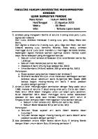
Service Training Description of the modules The machine is equipped with two control/monitoring modules. These modules are fitted with control lamps on the inputs/outputs, which are used to monitor the applied signals. Module travel lever monitoring (part number 880 255 02)
LED 2 LED 3
LED 1
a bc
The following applies when measuring the signal level: PIN digit. inputs (HIGH-active) digit. input (LOW-active) digit. output Analogue input (PIN 8) Analogue input (PIN 7)
Potential with LED on Potential with LED off Operating voltage +12V Voltage < 1V Ground Input open/no ground Operating voltage (UB - 0,7V) < 1V Current on PIN 8 = 3,5mA to 20,5mA (depending on angle sensor) Voltage on PIN 7 against ground = 0,6V to 7,65V (depending on interval switch)
________________________________________________________________________________________ BW 100/120 AD Series 4 G7 BW 100/120 AC Series 4
Service Training Description of hardware: The inputs are designed in such a way, that the following table is valid: Input
Performance Remark
Input PIN12
HIGH-active
LED lights when applying positive voltage!
Input PIN13
LOW-active
LED lights when applying ground potential!
Input PIN14
HIGH-active
LED lights when applying positive voltage!
Input PIN15
HIGH-active
LED lights when applying positive voltage!
Input PIN16
HIGH-active
LED lights when applying positive voltage!
Pin assignment digital inputs Signal Name Initiator for brake
Module Pin 12
Button vibration on
13
Switch position vibration auto / manual Start signal
14
Bridge option America
16
15
Description Active-HIGH = Travel lever in braking position LED on LOW =Travel lever not in brake position LED off Active-LOW = Momentary contact function LED on HIGH = Normal status LED off Active-HIGH = autom. vibr. nominal on, LED on LOW = manual vibr. nominal on LED off Active-HIGH = Vibration may not switch on LED on LOW = Vibration may switch on LED off Active-HIGH = Vibration shut down at >6km/h LED on LOW = No vibration shut down at >6km/h LED off
Pin assignment analog inputs Signal Name 8,5 Volt Voltage output
Module Pin 9
Analog input 1
8
Analog input 2
7
Description Output 8,5 V for voltage supply of angle sensor. Function o.k. à LED on Input for signal 4-20mA Connection for travel lever angle sensor Input for signal 0-8,5V 12-stage switch (stage 1 = off)
Pin assignment outputs Signal Name Brake
Module Pin 3
Water sprinkling system
4
Vibration
5
Backup alarm
6
Description HIGH = Brake valve picked up LED on LOW = Brake valve not picked up LED off HIGH = Sprinkling on LED on LOW = Sprinkling off LED off HIGH = Vibration on, LED on LOW = Vibration off LED off HIGH = Buzzer on, LED on LOW = Vibration off LED off
________________________________________________________________________________________ BW 100/120 AD Series 4 G8 BW 100/120 AC Series 4
5
Vibration ein 5) Vibration ON 6) Backup alarmRückfahrwarnsummer 7)IntervalIntervallschalter switch SprinklerBerieselung system
15) Startsignal Brücke Option Amerika 16) Bridge Option America
13) Button Vibration Taster Vibration 14) Switch Vibtation Auto/Manual Schalter Vibration Auto / Manuell
10)Ground potential Masseanschluß 11)Ground potential Masseanschluß 12) Proximity switch Brake Initiator Bremse
Winkelsensor Fahrhebel 8) Angle Sensor Travel lever 9) Output 8,5 Volt Ausgang 8,5 Volt
4
4) Output Sprinkler system Ausgang Berieselung
16
14
13
12
11
10
9
8
7
6
2 3
1
Versorgungsspannung (+U B) 1)Power Supply (+UB) 2)Power Supply (+UB) Versorgungsspannung (+UB ) 3)Brake Bremse
LED 2 LED 3
LED 1
Service Training
Signal level:
a bc
________________________________________________________________________________________ BW 100/120 AD Series 4 G9 BW 100/120 AC Series 4
Service Training Description of function Switching off If operating voltage is applied to the module (PIN1/2 UB, PIN10/11 ground), LED1 will light as a control light. LED 2 flashes as Stay-Alive-Indicator („Live Sign of Module“), but with a flashing frequency which depends on the current on input PIN 8 (analogue input 1).
Angle sensor: The machine is equipped with an angle sensor under the driver’s seat, mounted to the switch guide plate of the travel lever. The angle sensor reports the travel lever position back to the module. The sensor works with an output current of 4-20 mA.
Angle sensor
When replacing the sensor, a zero adjustment will be automatically performed as followed.
________________________________________________________________________________________ BW 100/120 AD Series 4 G 10 BW 100/120 AC Series 4
Service Training Neutral position of angle sensor The zero point of the angle sensor is automatically adjusted via the module. Once the travel lever is in neutral position the brake initiator (on the travel lever) (Pin 12) is actuated. The zero position is thereby recognized. Should the brake initiator be defective or a cable is broken the last value is set as default for the zero point. If LED2 (on the module) flashes in intervals of one second and LED3 lights permanently, the zero point is reached.
In it iator fo r Brake
LED lights with trav el lev er in zero posit ion
________________________________________________________________________________________ BW 100/120 AD Series 4 G 11 BW 100/120 AC Series 4
Service Training Defect on angle sensor The current of the functional angle sensor is in the range from 4mA to 20mA. A current flow of 22mA on Pin 8 of the module indicates a sensor fault (sensor defective, short circuit, or sensor not connected, etc.). LED2 and LED3 are then used as indicators. LED2 flashes fast (with 80 Hz), LED3 shows permanent light. Constant voltage monitoring The flashing frequency of LED 2 indicates whether the output voltage of 8.5 V on Pin 9 is outside the permissible tolerance. If this voltage is not high enough, the angle sensor will not work correctly and the output signal of the sensor is undefined. For this reason the flashing frequency of LED2 is set to 80 Hz, if the voltage is too low. This always takes place in case of a low voltage level on Pin 9. This may be caused by a too low supply voltage for the module (with UB < 9,5V the voltage of 8,5V can no longer be maintained on PIN 9) or by a defect of the module. The complete module works from a minimum voltage of UB = 6,5V. However, the analogue inputs only work from a supply voltage of 9,5 Volt, since the sensor supply voltage of 8,5V can only be generated if this input voltage is available.
The following functions are influenced by the angle sensor: -
Automatic vibration ON/OFF Sprinkler system water off after 30 sec. If travel lever is in 0-position Backup protection Checking of neutral position
________________________________________________________________________________________ BW 100/120 AD Series 4 G 12 BW 100/120 AC Series 4
Service Training Vibration control Manual vibration If no voltage is applied to PIN 14 (manual vibration on), vibration can be switched on via button input (vibration on) on PIN 13. Vibration is always switched on or off when a clear ground potential is detected on Pin 13. If vibration is switched on, the LED on Pin 5 lights up. If the vibration button is actuated again, vibration is switched off. In case of a bridge (Active-HIGH-Signal) on PIN 16 vibration switched off at a speed higher than 6 km/h and on again at a speed below 6 km/h. Without a bridge on PIN 16 the vibration is not switched off above 6 km/h.
Auto Vibration ON
Manuell Vibration
Travel lever
Push button Vibration
Vibration
Fig. 1: Manual vibration control with HIGH-Signal on PIN 16
________________________________________________________________________________________ BW 100/120 AD Series 4 G 13 BW 100/120 AC Series 4
Service Training Automatic vibration control (optional) If a positive voltage is applied to PIN 14 (automatic vibration on) the LED on PIN 14 lights up and the vibration (PIN 5) is switched on and off in dependence on the travel lever position. With a bridge (Active-HIGH-Signal) on PIN 16 the vibration (output, PIN 5) is switched off with the travel lever in a position 6 km/h. Without the bridge (LOW-Signal) on PIN 16 the vibration (output, PIN 5) is only switched off at a speed < 1 km/h.
Auto Vibration ON
Travel lever
Push button Vibration
Fig.: Automatic vibration control with Active-HIGH-Signal on PIN 16 (Active High means + 12 V)
________________________________________________________________________________________ BW 100/120 AD Series 4 G 14 BW 100/120 AC Series 4
Service Training Water sprinkling control The sprinkler intervals are controlled by connection of a 12-stage switch to PIN 7. This switch switches resistors in 500 Ω-steps from 500 Ω to 6 kΩ. Sprinkling stages for pressurized sprinkler system
Stufe 12 Stufe 11 Stufe 9
Stufe 10
Stufe 12 Stufe 11 Stufe 10
Stufe 8
12-Step switch
Stufe 7 Stufe 6 Stufe 5 Stufe 4 Stufe 2
Stufe 3
Stufe 1
Travel lever
Sprinkler system
The total cycle (time for activation and deactivation phase) takes 15 seconds. The sprinkling intervals are set according to the following table: Stage Activation time Deactivation time 1 0,0 s 15,0 s 2 1,0 s 14,0 s 3 2,0 s 13,0 s 4 3,0 s 12,0 s 5 4,0 s 11,0 s 6 5,0 s 10,0 s 7 6,0 s 9,0 s 8 7,0 s 8,0 s 9 8,0 s 7,0 s 10 10,0 s 5,0 s 11 12,5 s 2,5 s 12 15,0 s 0,0 s
Cycle time 15s 15s 15s 15s 15s 15s 15s 15s 15s 15s 15s 15s
________________________________________________________________________________________ BW 100/120 AD Series 4 G 15 BW 100/120 AC Series 4
Service Training After stopping the machine (travel lever in neutral, evaluation of analogue signal on PIN 8) sprinkling continues with the set interval for another 30 seconds (pressure sprinkling). After this time sprinkling will only be resumed after moving the travel lever out of neutral. If the switch is in stage 12 (permanent sprinkling), sprinkling will continue after the 30 seconds, without any temporal limitation! Should be used for inspection with the machine stopped to check nozzles, pump etc. Gravity feed sprinkler system If no 12-stage switch is connected, but the gravity sprinkler switch (S05 on output PIN 4) instead, the output will permanently switch a High signal. The sprinkling system is triggered via this switch. With the machine stopped (travel lever in neutral position, evaluation of analogue signal on PIN 8) the HIGH-signal will still be emitted at PIN4 for another 30 seconds, after this it will be set to LOW-signal, until the travel lever is moved out of neutral again.
12-Step switch
12 step switch not connected
Travel lever
30 seconds
Output sprinkler system
Fig. 2: Gravity feed sprinkler system With both sprinkling systems the sprinkling cycle time is independent from the displacement of the travel lever, i.e. from the travel speed of the machine. Only the neutral position is of significance for the automatic shut down of the sprinkling system after 30 seconds.
________________________________________________________________________________________ BW 100/120 AD Series 4 G 16 BW 100/120 AC Series 4
Service Training Description of the seat contact module (part-no.: 88003042)
+
-
OUT
4 3
LED 1
LED 3
LED 4
LED 5
LED 2
RS 232
2
1
30
Pin assignment:
PIN 1 2 3
Signal IN (Active LOW) IN (Active LOW) IN (Active HIGH)
4 BTS OUT OUT + 30 87 87a 15/54
IN (Active HIGH) OUT (BTS) PWM PWM + Relay – Contact Relay – Contact Relay – Contact Supply voltage Ground
Description Seat contact switch Seat contact switch Travel lever sensor 0-position Oil pressure Engine solenoid pickup winding Not used Not used Ground Engine solenoid holding winding Normally closed 10-39 V
-
________________________________________________________________________________________ BW 100/120 AD Series 4 G 17 BW 100/120 AC Series 4
Service Training Description of hardware The inputs are designed in such a way, that the following table is valid: Input
Performance Remark
Input PIN1
LOW-active
LED lights when applying ground potential!
Input PIN2
LOW-active
LED lights when applying ground potential!
Input PIN3
HIGH-active
LED lights when applying positive voltage!
Input PIN4
HIGH-active
LED lights when applying positive voltage!
Pin assignment digital inputs Signal Name Module Pin Seat contact switch 1 Seat contact switch (is presently not evaluated) Sensor Travel lever neutral position Engine – oil pressure
Active-LOW = Driver seated HIGH = Driver standing Active-LOW = Driver standing HIGH = Driver seated
LED on LED off LED on LED off
3
Active-HIGH = Brake released LOW = Brake applied
LED on LED off
4
Active-HIGH = Oil pressure present LOW = Oil pressure not present
LED on LED off
2
Pin assignment outputs Signal Name Module Pin Relay contact 15 + 87 30 + 87 (normally open) BTS
Description
BTS
Description HIGH = Holding winding of engine solenoid is switched on LED on LOW = Holding winding of engine solenoid is not switched on LED off HIGH = Holding winding of engine solenoid is switched on LED on LOW = Holding winding of engine solenoid is not switched on LED off
________________________________________________________________________________________ BW 100/120 AD Series 4 G 18 BW 100/120 AC Series 4
Service Training Description of function
Travel lever in brake lock and driver standing
Travel lever is actuated
Engine emmidiately OFF
Driver seated
Travel lever is actuated
Druíver gets up during travel
Engine shuts OFF after 2 seconds
Driver sits down within 2 seconds and oil pressure is present
Engine starts again by centrifugal movement
________________________________________________________________________________________ BW 100/120 AD Series 4 G 19 BW 100/120 AC Series 4
Service Training Description of function Switch ignition on and start the engine • Stay-Alive-(Live Signs) LED flashes in one second intervals. • Engine running Shut down the engine immediately • If the driver seat is not occupied (PIN 2 has HIGH–Signal) and the travel lever is actuated (PIN 3 has Active–HIGH–Signal), the module will simulate a oil pressure fault. Relay (PIN 30 + 87) switches immediately for half a second and LED6 lights for half a second. • The holding winding of the engine solenoid is not energized for half a second and the engine is shut down. Engine shut down with time delay • The driver's seat is occupied (PIN 2 has Active–LOW–Signal) and the travel lever is in neutral position (PIN 3 has LOW–Signal). • When leaving the driver’s seat (PIN 2 has LOW–Signal) after shifting the travel lever out of neutral (PIN 3 has Active–HIGH–Signal), the warning buzzer is activated. • After 2 seconds the relay (PIN 30 + 87) is switched on for half a second and LED6 lights for half a second. • The holding winding of the engine solenoid is not energized for half a second and the engine is shut down. Restarting the engine • If the engine has shut down as described in point 3.4 it can be restarted within 2 seconds after occupying the driver’s seat. This is only possible if the engine is still rotating and oil pressure (PIN 4 has Active–HIGH–Signal) is present. • This is accomplished by switching on the BTS-output (PIN BTS) for 1 second. LED5 lights for 1 second. • The pickup winding of the engine solenoid is energized for half a second and the engine is restarted.
________________________________________________________________________________________ BW 100/120 AD Series 4 G 20 BW 100/120 AC Series 4
Inhaltsverzeichnis: table of contents: Blatt Nr.: sheet no.:
BW 100 AD/AC−4, BW 120 AD/AC−4 BW 100 AD/AC−4, BW 120 AD/AC−4
Zeichnungsnummer drawing − no.
Funktionsgruppe
function unit
Stromlaufplan Versorgung, Motor, Starten, Not−Aus Vibration, Berieselung
001 002 003 004 005 006 007
880 100 51 880 100 51 880 100 51 880 100 51 880 100 51 880 100 51 880 100 51
Sitzkontakt
Circuit Diagram supply, engine, starting unit, emergancy shut off vibration, sprinkler system brake, flow divider, rotary beacon, edge cutter switch seat contact
Bremse, Mengenteiler, Rundumkennleuchte, Kantenschneidg. Arbeitsbeleuchtung, Blinkbegrenzung, Arbeitsbeleuchtung
working head lights, flash and position illum., working head lights
Wetterschutzkabine
cabin, weather protection
009 101
880 100 51 880 100 51
Zentralelektrik Bauteilliste
cross − bonding − box component listing
4.2.2004 Kneip 4.2.2004 Nallin
Stromlaufplan circuit diagram
001
001
880 100 51 001
2 S00
30 3:1
30
2 C
4
X6:14 2
H08
H49
2:16
V43
H09
2
H52
X6:16
D+ P00
X6:6
G02 B
2 − Generator generator
F00
F141
2:18
G01 7:2 +
2:4
X1:3 B53
3
_t
Batterie − battery
X1:4 B06
− H(−)
H(−)
4
X11:3
G
X6:2
1
Glühüberwachung indicator light, glowing
X1:5
2:12
2
2:9
Betriebsstundenzähler engine hour meter X25:C
30
87a
2:19 A15 Überwachungsmodul monitoring module
87 K96 2:13
UPM4 5:2
option Sitzkontakt seatswitch
3X8A
87 Glühkerze Header plug X1:6
X10:2
2:3
X10:1 AW Y13
R03 option M−
30
F139 4:9
K05 3:12
X6:1
X11:2
1 2
87a
2:15 K05
(A4) V44
2:16
X2:4
4:3
X6:10
P −
K37
P01
3:2
B BOX A F139 2
K22 5:19
+
V45 (A5)
H(−) 2:6 B
1 V45 2:11
X11:5
X6:17
X11:4
X12:1 L
X11:6
X12:2 IG
level gauge
X1:1
Kraftstoffanzeige
30 BOX A X1:2
2:19
1
K05 2:18
R02
2:8 X6:20
H
X2:3
2:11
UPM15 3:1
87
R02
R21 1
V43
87a
BOX A F48
B
HW M01 −
M−
M− 4:3
Hubmagnet Motor shut off solenoid engine
31 3:1
31
Hauptsicherung fuse, main
Temperaturgeber Kuehlmittel temperature switch, collant
Geber Kraftstofftank sender, level gauge
Starter starter
2:16
Druckschalter Motoröl pressure switch, engine oil
Sicherung Generator fuse, generator
4.02.2004 Kneip 4.02.2004 Nallin
Versorgung, Motor, Starten, Not−Aus supply, engine, starting unit, emergancy shut off
1
1
880 100 51 002
X2:1
2:7 V45 V43 (A3) 2 1
12
8 Not−Aus−Schalter emergancy shut off V45 5:12
R02
R09
22
K05 3:2
S01
Meldeleuchte Motoröldruck indicator light, engine oil pressure
2
11
R02
K32 7:2
21
ST(50)
86 K96 85
30
B(30)
Meldeleuchte Motorüberhitzung indicator light, engine overheating
1
50a
X2:2
F119
4:2
2:9
Meldeleuchte Ladekontrolle indicator light, charge control
V41 (A1)
2
3
S01
1
19 17
BOX A F119
S01
F119 2:11
58 2 15 6:1
15 BOX A 3:1
D
Box A F04
G01
15 54
X25:A
X25:B
Zündstartschalter ignition switch
R02
2
P0123 P01
30
2:9
30 6:1 2
30 BOX A
2:14
2:19 15 BOX A
15 BOX A 4:1
2:17 UPM15 X3:3
UPM15 5:1
BOX A F03
E
K05
2:20
BR/BN
Aufnehmer Fahrhebel transducer travel lever
Intervallschalter interval switch Druckberieselung press. water sprink sys.
Initiator Bremse proximity switch, brake B08
BOX A F68
V48 (A8) F45 4:12
5 X14:1
A
2 K05 5:1
1
1
Vibrationsschalter man./autom. switch, vibration, man./autom.
3 B39 2
BL/BU
X22:1
13
X13:3 S08
0−11
X18:3
X18:2
X14:2
X13:1
A01
3 X3:1
X3:6
S164
14
X3:2
B08
X14:3
X18:1
SW/BK
1 X13:2
X3:4
1 8
11 (GND)
1 (15/54)
14
16 15
A03 Modul Vibration modile vibration
12
X22:2 S164 4:13
A03 4:1 3
13 A03:12
6
5:2
S05
X7:1
A15 X6:9
X7:1 85
4
10 (GND)
5
X3:5
X20:1
13
K78
14
3:16 87
86
X7:1
K117
4 +
4 X20:2
X7:2
X5:4 2:20 2:19
H14 X8:2
−
1
X1:9 86 K79
85
85
option Kantenschneidgerät egde cutter
X8:1
5:6
Druckberieselung press. water sprink sys.
2
X19:3
S13
S12
V42
3
3
Schwerkraftberieselung sprinkling, gravitation
V42 (A2) option
30
1
86
+
85
−
X19:6 X15:1 +
Y06 1
M02 V02
2
−
X16:2 X19:8
X15:2
X19:8
31 Taster Vibration switch vibration
Warnsummer warning buzzer
31 4:1 Überwachungsmodul monitoring module Berieselungsschalter switch sprinkler system
3:20
4:17
3:17 Magnetventil Vibration solenoid valve, vibration
Emulsionspumpe emulsion pump Fußschalter switch, foot
2.04.2004 Kneip 2.04.2004 Nallin
87a
X16:1
M03
2
30
X19:5
K78
Y71
K79 3:11 87
87a
AC−Typen AC−typen
86 K05
B08
3:2
Schwerkraftberieselung sprinkling, gravitation
9 (8,5V)
7
Druckberieselung press. water sprink sys.
3:2
Vibration, Berieselung vibration, sprinkler system
Berieselungspumpe sprinkler pump
Berieselungsventil solenoid valve sprinkler
1
1
880 100 51 003
3:17 15 BOX A 3:15 A03
G BOX A F23
option
F
BOX A F45
option
7
6
Schalter Rundumkennleuchte switch, rotary beacon
option
11 S01
2:14
3:17 F45
F139
2:16 12
3:16
S164
30 K117
UMP3 5:2
3:13 87
87a
X5:3 Taster Signalhorn switch warning horn
Schalter Kantenschneidgerät switch, edge cutter
S03
13
S38
13
14
14
86 K11
85
23
0
14
X6:11
13
102 S34
24
30 X24:A
K11 4:9 87
X24:B V09
V08 87a 1
2
2
1
1 Y48
X19:2
X1:8 2:10 H(−)
2
X4:1
H01 H(−)
X1:7
X1:10
+
5:5
1
1 Y21
Y20
E32 +
Meldeleuchte Bremse indicator light brake
1
2
2
−
B11 X4:2
−
Y90
Y04
1
X19:8 X24:C 2
2 2:20
3:20
X5:4
M−
31
31 5:1
Bremsventil solenoid valve, brake
Signalhorn warning horn
4:10 Mengenteiler flow divider Rundumkennleuchte rotary beacon
4.02.2004 Kneip 4.02.2004 Nallin
Bremse, Mengenteiler, Signalhorn, Rundumkennleuchte, Kantenschneidgerät brake, flow divider, rotary beacon, edge cutter
Magnetventil Hydr.−umsch. solenoid valve, hydr. switch over Kantenschneidgerät ab edge cutter, down
1
Kantenschneidgerät auf edge cutter, up
1
880 100 51 004
3:17 K05
UPM15
3:8
2:16 UPM4 3:3
A03:12 UMP3
4:5
86 K137
4
3
15/54
85
2 1
15/54 K137
30 A68 Modul Sitzkontakt modul seat contact
5:3 X5:1
X5:2
X23:2
X23:3
2
87
3:8
V42
87
X21:1 + −
H20
Sitzkontaktschalter switch, seat contact
30
BTS
X19:4
X6:12
3
S06
87a
1
86
H82
X21:2 X19:8
X23:1 X5:4
4:20
4:5
H(−)
H(−)
K22 Warnsummer warning buzzer
85 2:15 V45
6:2
31
31 6:1 5:10
2:14
Meleleuchte Sitzkontakt indicator light,drivers seat contact
option
4.02.2004 Kneip 4.02.2004 Nallin
Sitzkontakt switch seat contact
1
1
880 100 51 005
2:19 15 3:20
ZA/option StVZO Beleuchtung 2
30 BOX B F07
F
C
6
3
A
BOX B F08
B
BOX B F11
BOX B F12 2
1
Schalter Blinker switch indicator 13
23
14
24
L0R S37
Beleuchtungsschalter STVZO switch, lighting STVZO S15
Blinkgeber flasher
11
23
49L
Überwachungsmodul monitoring module L
D
14
24
24
5
X6:8 X9:2
X6:18 X9:3 V13
X9:4
X19:1
X1:11
V12
24 X27:1
X6:7 H06
X27:2
ZA/option Arbeitsbeleuchtung
X27:4
X27:3
1 X28:1
H06 2 H(−)
24
BOX B F10 4
X6:19
X9:1
S14
5:8
H(−) 6:8
X28:2
1
H05
1
E08
X28:4 1 E12
1
2
E09
X28:3
6:3 H(−)
E10 1
2
Meldeleuchte Warnblinker indicator light, hazard light
1
E11 2
X32:1 X33:1 1 E27 E28 1
E14 2
1
2
E13 2
X31:1 X30:1 1 E23 E25 1
1
E15 2
2 X30:2
2 X31:2
2
2
2 X32:2
X27:5
5:19 31 Schalter Warnblinker switch, hazard light
23
E
BOX B F09
R A15
14
S53
A02
82
01
23
01 12
23
13 01
49R
31
13
S53
012 012
30
Schalter Arbeitsbel. hinten switch, working head lights rear
Schalter Arbeitsbeleuchtung switch, working light
L0R
Meldeleuchte Blinker indicator light, indicators
X28:5
X9:5
X33:2
X19:7
X9:6 31
Blinkleuchte VL indicator front, LH
Blinkleuchte VR indicator front, RH
Blinkleuchte HL indicator rear, LH
Parkleuchte links parking light, LH
Blinkleuchte HR indicator rear, RH Schlußleuchte links tail light, LH
4.02.2004 Kneip 4.02.2004 Nallin
Scheinwerfer vorne links working head light front, LH
Parkleuchte rechts Scheinwerfer vorne rechts parking light, RH working head light front, RH Schlußleuchte rechts tail light, RH
Arbeitsbeleuchtung, Blinkbegrenzung, Arbeitsbeleuchtung StVZO working head lights, flash and position illumination,working head lights StVZO
7:1
Scheinwerfer hinten links working head light rear, LH Scheinwerfer hinten rechts working head light rear, RH
1
1
880 100 51 006
2:11
K32
2:3
G01
F39
1 Sicherung fuse 2
30
K32 7:14 87
87a
6 012
6 012
S20
S21 2
3
2
3 K32
86
+ M04
85 M − + M06
+ M07
M
M
−
− + M05 M −
6:20
31
31 Scheibenwischer vorn Scheibenwischer hinten windsceen wiper motor, front windscreen wiper motor, rear Scheibenwascher vorn windscreen washer motor, front Scheibenwascher hinten windscreen washer motor, rear
7:9
option
4.02.2004 Kneip 4.02.2004 Nallin
Wetterschutzkabine cabin, weather protection
1
1
880 100 51 007
X6:1−20 9 8 7 6
3 6
X11:2−6
5 4 3 2 1
K37
2 5 4
201918 1716151413 121110 V41
057 664 03
A03
A15
1 2 3 4 5 6 7 8 9 10 11 12 13 14 15 16
Zentralstecker Sammelanzeige (Ansicht von hinten) mainplug monitoring module (view from backside)
option Rundumkennleuchte rotary beacon
K22 30
1
1
1
2
2
2
AC typen
K11
86
K79
K78 30 87
30 87
V42
V43
V44 V45
1 3
1
1 4
V46
5 2
2
2
R09
1
2
R21
1
V48 1
1
1 6
2
V47
7 2
8 2
2
30 87
87a 87 85
A02
30 85
49R 31 82
86
87a 87 L R 30 49L
K05
85 87a 86 85 87a 86 85 87a 86 30 30 30 87 87 87 85 87a 86 85 87a 86 85 87a 86
K96
option Stvzo Beleuchtung
option Kantenschneidgerät edge cutter
option Sitzkontakt seatswitch
A68
X10:1−2 1
K117
K137 option Sitzkontakt seatswitch
Box A
Box B F11
F68
F12
F139
F08
F04
F09
F119
F10
F03
F07
F45
Y13
F23
2
F48 option Hubmanget Motor shut off solenoid, engine
4.02.2004 Kneip 4.02.2004 Nallin
BTS 4 3 30 87 87a 15/54
2
1
Zentralelektrik cross − bonding − box
Stvzo Beleuchtung StVZO lights Arbeitsscheinwerfer working lights
1
1
880 100 51 009
Name
4. 2. 4 Kneip
Bauteilliste component listing 1 3 101
880 100 51
Bl. 003 006 003 002 003 006 009 008 008 005
Pf. 6 6 10 17 7 11 4 9 15 13
Benennung
A01 A02 A03 A15 A15 A15 A15 A66 A67 A68
Intervallschalter Blinkrelais Modul Vibration Platine Ueberwachungsmodul Platine Ueberwachungsmodul Platine Ueberwachungsmodul Platine Ueberwachungsmodul Elektronik Steuereinheit Eingabeeinheit Modul Sitzkontakt
interval switch indicator relay modul, vibration Printed circuit board, monitoring module Printed circuit board, monitoring module Printed circuit board, monitoring module Printed circuit board, monitoring module Electronic control unit Keyboard Modul seat contact
B06 B08 B11 B39 B53
002 003 004 003 002
6 2 7 10 5
Druckschalter Motoroel Naeherungsinitiator Fahrhebel ’0’−Stell. Signalhorn Aufnehmer Fahrhebel Temperaturgeber Kuehlmittel
Pressure switch, engine oil Proximity switch, travel lever ’0’ pos. Warning horn Transducer, travel lever Temperature switch, collant
E08 E09 E10 E11 E12 E13 E14 E15 E23 E25 E27 E28 E32
006 006 006 006 006 006 006 006 006 006 006 006 004
5 6 7 8 11 10 12 13 14 15 17 18 10
Blinkleuchte vorne links Blinkleuchte hinten links Blinkleuchte vorne rechts Blinkleuchte hinten rechts Parkleuchte links Schlussleuchte links Parkleuchte rechts Schlussleuchte rechts Arbeitsscheinwerfer vorne links Arbeitsscheinwerfer vorne rechts Arbeitsscheinwerfer hinten links Arbeitsscheinwerfer hinten rechts Kennleuchte
Indicator, front, lh. Indicator, rear, lh. Indicator, front, rh. Indicator, rear, rh. Parking light, lh. Tail light, lh. Parking light, rh. Tail light, rh. Working head light, front, lh. Working head light, front, rh. Working head light, rear, lh. Working head light, rear, rh. Warning light
21W 21W 21W 21W 10W 10W 10W 10W 55W 55W 55W 55W 5,5A
F00 F03 F04 F07 F08 F09 F10 F11 F12 F23 F39 F45 F48 F68 F119 F139 F141
002 003 002 006 006 006 006 006 006 004 007 004 002 003 002 002 002
1 11 10 3 6 11 13 14 17 7 9 17 19 17 16 14 2
Hauptsicherung Batterie Sicherung Vibration Sicherung Instrumente Sicherung Warnblinker Sicherung Blinker u. Arbeitsscheinw. Sicherung Park− u. Schlussl. links Sicherung Park− u. Schlussl. rechts Sicherung Scheinwerfer links Sicherung Scheinwerfer rechts Sicherung Signalhorn Hauptsicherung Kabine Sicherung Kantenschneidgeraet Sicherung Gluehanlage Sicherung Potential 30 Sicherung Motor Sicherung Hubmagnet Motor Sicherung Hydraulikölkühler
Fuse, main, battery Fuse, vibration Fuse, gauges Fuse, hazard light Fuse, indicators a. work. head light Fuse, parking and tail light, lh. Fuse, parking and tail light, rh. Fuse, head light, lh. Fuse, head light, rh. Fuse, warning horn Main fuse, cab Fuse, edgecutter Fuse, glow plug system Fuse, potential 30 Fuse, motor Fuse, shut off solenoid, engine Fuse , cooling air blower
80A 10A 10A 15A 15A 15A 15A 15A 15A 10A 15A 10A 10A 20A 10A 30A 50A
G01 G02
002 1 002 2
Batterie Generator
Battery Generator
88 AH 50A
H01 H05 H06 H06 H08 H09 H14 H15 H20 H23 H49 H52 H70 H82
004 006 006 006 002 002 003 002 005 002 002 002 002 005
4 9 3 4 4 6 7 7 7 8 5 12 9 10
Meldeleuchte Bremse Meldeleuchte Blinker Meldeleuchte Warnblinker Meldeleuchte Warnblinker Meldeleuchte Ladekontrolle Meldeleuchte Oeldruck Motor Warnsummer Rueckwaertsfahrt Meldeleuchte Motorluftfilter Meldeleuchte Sitzkontaktschalter Meldeleuchte Hydraulikoelfilter Meldeleuchte Motorueberhitzung Anzeige Gluehueberwachung Anzeige Wasser im Diesel Warnsummer Sitzkontakt
Indicator light, brake Indicator light, indicators Indicator light, hazard light Indicator light, hazard light Indicator light, charge control Indicator light, engine oil pressure Back−up alarm buzzer Indicator light, engine air filter Indicator light, drivers seat contact Indicator light, hydr.oil filter Indicator light, engine overheating Glow plug indicator Indicator water in fuel Warning buzzer, seat contact
K05 K11 K22 K32 K37 K37 K78 K79 K96 K117 K137
003 004 005 007 002 009 003 003 002 003 005
2 9 19 14 12 18 16 11 13 13 3
Relais Startstrom Relais Klemme 30 auf 15 Relais Hubmagnet Motor Relais Kabine Zeitrelais Zeitrelais Relais Emulsionsberieselung Relais Berieselungspumpe Relais Motoroeldruck Relais Kantenschneidgeraet Relais Sitzkontaktschalter
Relay, starting current Relay, terminal 30 to 15 Relay, shut off solenoid, engine Relay, cabin Timing relay Timing relay Relay, emulsion sprinkler sys. Relay, sprinkler pump Relay, engine oil Relay, edge cutter Relay, switch, drivers seat
BOSCHW BOSCHW BOSCHW BOSCHW 5 SEC.
M01 M02 M03 M04 M05 M06 M07
002 003 003 007 007 007 007
19 19 17 9 11 10 12
Starter Berieselungspumpe Emulsionsberieselungspumpe Scheibenwischermotor vorne Scheibenwischermotor hinten Scheibenwaschermotor vorne Scheibenwaschermotor hinten
Starter Sprinkler pump Emulsion sprinkler pump Windscreen wiper motor, front Windscreen wiper motor, rear Windscreen washer motor, front Windscreen washer motor, rear
1,4KW 6,4A 6,4A 7,5A 2,5A 2,5A 7,5A
P00 P01
002 4 002 10
Betriebsstundenzaehler Tankanzeige
Operating hour meter Level gauge
R02 R02 R02 R03 R09 R20 R21 R21 R22
002 002 002 002 002 002 002 002 002
Gluehkerze Gluehkerze Gluehkerze Geber Tankanzeige Vorwiderstand Widerstand Widerstand Widerstand Widerstand
Glow plug Glow plug Glow plug Sender, level gauge Dropping resistor Resistor Resistor Resistor Resistor
18 18 19 10 3 9 3 8 8
title
TYP 4X21WATT MAX1,5A MAX1,5A
MAX 300MA 4−20 mA
BOSCHW BOSCHW BOSCHW BOSCHW BOSCHW
8A 8A 8A 82 OHM 82 OHM
4. 2. 4 Kneip
Bauteilliste component listing 2 3 102
880 100 51
Name
Bl.
Pf. Benennung
title
S00 S01 S01 S03 S05 S06 S08 S12 S13 S14 S15 S20 S21 S34 S37 S38 S53 S53 S164
002 002 002 004 003 005 003 003 003 006 006 007 007 004 006 004 006 006 003
18 16 16 7 10 3 12 4 5 3 13 9 11 17 6 9 17 19 16
Startschalter Schalter NOT AUS Schalter NOT AUS Taster Signalhorn Berieselungsschalter Sitzkontaktschalter links Vibrationsschalter man./autom. Vibrationsschalter Fahrhebel links Vibrationsschalter Fahrhebel rechts Warnblinkschalter Beleuchtungsschalter StVZO Schalter Scheibenwischer vorne Schalter Scheibenwischer hinten Schalter Kantenschneidgeraet Schalter Blinker Schalter Kennleuchte Schalter Arbeitsbeleuchtung Schalter Arbeitsbeleuchtung Fusschalter
Starter switch Switch, emergency off Switch, emergency off Push button, warning horn Switch, sprinkler system Switch, seat contact, lh. Switch, vibration, man./autom. Switch, vibration, travel lever, lh. Switch, vibration, travel lever, rh. Switch, hazard light Switch, lighting StVZO Switch, windscreen wiper, front Switch, windscreen wiper, rear Switch, edge cutter Switch, indicator Switch, warning light Switch, working lights Switch, working lights Switch, foot
V02 V08 V09 V12 V13 V41 V42 V43 V44 V45 V48
003 004 004 006 006 002 003 002 002 002 003
18 17 19 9 8 3 8 4 16 6 16
Diode Diode Diode Diode Diode Diode (A1) Diode (A2) Diode (A3) Diode (A4) Diode (A5) Diode (A8)
Diode Diode Diode Diode Diode Diode (A1) Diode (A2) Diode (A3) Diode (A4) Diode (A5) Diode (A8)
X1:1 X1:2 X1:3 X1:4 X1:5 X1:6 X1:7 X1:8 X1:9 X1:10 X1:11 X2:1 X2:2 X2:3 X2:4 X3:1 X3:2 X3:3 X3:4 X3:5 X3:6 X4:1 X4:2 X5:1 X5:2 X5:3 X5:4 X5:4 X5:4 X6:1 X6:1−20 X6:2 X6:3 X6:4 X6:6 X6:7 X6:8 X6:9 X6:10 X6:11 X6:12 X6:13 X6:14 X6:15 X6:16 X6:17 X6:18 X6:19 X6:20 X7:1 X7:1 X7:1 X7:2 X8:1 X8:2 X9:1 X9:2 X9:3 X9:4 X9:5 X9:6 X10:1 X10:1−2 X10:2 X11:2 X11:2−6
002 002 002 002 002 002 004 004 003 004 006 002 002 002 002 003 003 003 003 003 003 004 004 005 005 004 003 004 005 002 009 002 002 002 002 006 006 003 002 004 005 002 002 002 002 002 006 006 002 003 003 003 003 003 003 006 006 006 006 006 006 002 009 002 002 009
3 2 5 6 10 16 7 2 14 13 14 20 20 19 15 9 10 2 2 5 10 10 10 3 3 17 5 17 3 17 6 10 8 8 12 3 11 7 9 4 7 8 3 7 6 5 8 6 10 5 5 5 5 7 7 5 7 11 13 5 6 16 2 15 13 18
FAHRERSTAND FAHRERSTAND FAHRERSTAND FAHRERSTAND FAHRERSTAND FAHRERSTAND FAHRERSTAND FAHRERSTAND FAHRERSTAND FAHRERSTAND FAHRERSTAND FAHRERSTAND FAHRERSTAND FAHRERSTAND FAHRERSTAND FAHRERSTAND FAHRERSTAND FAHRERSTAND FAHRERSTAND FAHRERSTAND FAHRERSTAND RUNDUMKENNLEUCHTE RUNDUMKENNLEUCHTE FAHRERSTAND FAHRERSTAND FAHRERSTAND FAHRERSTAND FAHRERSTAND FAHRERSTAND ARMATURENPULT
Operators platform Operators platform Operators platform Operators platform Operators platform Operators platform Operators platform Operators platform Operators platform Operators platform Operators platform Operators platform Operators platform Operators platform Operators platform Operators platform Operators platform Operators platform Operators platform Operators platform Operators platform Rotary beacon Rotary beacon Operators platform Operators platform Operators platform Operators platform Operators platform Operators platform Instrument board
ARMATURENPULT ARMATURENPULT ARMATURENPULT ARMATURENPULT ARMATURENPULT ARMATURENPULT ARMATURENPULT ARMATURENPULT ARMATURENPULT ARMATURENPULT ARMATURENPULT ARMATURENPULT ARMATURENPULT ARMATURENPULT ARMATURENPULT ARMATURENPULT ARMATURENPULT ARMATURENPULT FAHRHEBEL FAHRHEBEL FAHRHEBEL FAHRHEBEL FAHRERSTAND FAHRERSTAND FAHRERSTAND FAHRERSTAND FAHRERSTAND FAHRERSTAND E1/E2 Blende vorn E1/E2 Blende hinten HUBMAGNET
Instrument board Instrument board Instrument board Instrument board Instrument board Instrument board Instrument board Instrument board Instrument board Instrument board Instrument board Instrument board Instrument board Instrument board Instrument board Instrument board Instrument board Instrument board Travel lever Travel lever Travel lever Travel lever Operators platform Operators platform Operators platform Operators platform Operators platform Operators platform E1/E2 srceen front E1/E2 srceen rear Shut off solenoid
HUBMAGNET FAHRERSTAND FAHRERSTAND
Shut off solenoid Operators platform Operators platform
TYP
MAX 2A STECKER FE5B FE5B
MR756 MR756 MR756 MR756 MR756 MR756
Name
4. 2. 4 Kneip
Bauteilliste component listing 3
Bl. 002 002 002 002 002 002 003 003 003 003 003 003 003 003 003 003 003 003 003 006 004 003 005 003 003 006 003 003 004 005 003 003 005 005 003 003 005 005 005 004 004 004 002 002 002 006 006 006 006 006 006 006 006 006 006 006 006 006 006 006 006 006 006 008 008 008 008 008 008 008 008 008 008 008
Pf. 12 13 13 12 3 2 10 9 10 2 2 2 19 18 17 17 5 5 6 17 10 7 10 17 19 17 7 17 10 10 4 4 10 10 16 16 3 3 3 17 19 17 1 1 1 5 7 11 12 5 6 8 10 13 6 14 14 15 15 17 17 18 18 5 5 5 5 5 5 12 5 5 5 5
Benennung
X11:3 X11:4 X11:5 X11:6 X12:1 X12:2 X13:1 X13:2 X13:3 X14:1 X14:2 X14:3 X15:1 X15:2 X16:1 X16:2 X18:1 X18:2 X18:3 X19:1 X19:2 X19:3 X19:4 X19:5 X19:6 X19:7 X19:8 X19:8 X19:8 X19:8 X20:1 X20:2 X21:1 X21:2 X22:1 X22:2 X23:1 X23:2 X23:3 X24:A X24:B X24:C X25:A X25:B X25:C X27:1 X27:2 X27:3 X27:4 X27:5 X28:1 X28:2 X28:3 X28:4 X28:5 X30:1 X30:2 X31:1 X31:2 X32:1 X32:2 X33:2 X33:1 X35:1 X35:2 X35:3 X35:4 X35:5 X35:7 X35:8 X35:9 X35:10 X35:11 X35:12
FAHRERSTAND FAHRERSTAND FAHRERSTAND FAHRERSTAND GENERATOR GENERATOR SITZKONSOLE SITZKONSOLE SITZKONSOLE SITZKONSOLE SITZKONSOLE SITZKONSOLE BERIESELUNGSPUMPE BERIESELUNGSPUMPE EMULSIONSPUMPE EMULSIONSPUMPE ARMATURENPULT ARMATURENPULT ARMATURENPULT FAHRERSTAND FAHRERSTAND FAHRERSTAND FAHRERSTAND FAHRERSTAND FAHRERSTAND FAHRERSTAND FAHRERSTAND FAHRERSTAND FAHRERSTAND FAHRERSTAND FAHRHEBEL FAHRHEBEL FAHRERSTAND FAHRERSTAND FUßSCHALTER FUßSCHALTER Fahrersitz Fahrersitz Fahrersitz FAHRERSTAND FAHRERSTAND FAHRERSTAND FAHRERSTAND FAHRERSTAND FAHRERSTAND FAHRERSTAND FAHRERSTAND FAHRERSTAND FAHRERSTAND FAHRERSTAND FAHRERSTAND FAHRERSTAND FAHRERSTAND FAHRERSTAND FAHRERSTAND E1/E2 Blende vorn E1/E2 Blende vorn E1/E2 Blende vorn E1/E2 Blende vorn E1/E2 Blende vorn E1/E2 Blende vorn E1/E2 Blende hinten E1/E2 Blende hinten KEYBOARD KEYBOARD KEYBOARD KEYBOARD KEYBOARD KEYBOARD KEYBOARD KEYBOARD KEYBOARD KEYBOARD KEYBOARD
Operators platform Operators platform Operators platform Operators platform Generator Generator Seating unit Seating unit Seating unit Seating unit Seating unit Seating unit Sprinkler pump Sprinkler pump Emulsion sprinkler pump Emulsion sprinkler pump Instrument board Instrument board Instrument board Operators platform Operators platform Operators platform Operators platform Operators platform Operators platform Operators platform Operators platform Operators platform Operators platform Operators platform Travel lever Travel lever Operators platform Operators platform Foot−switch Foot−switch Driver‘s seat Driver‘s seat Driver‘s seat Operators platform Operators platform Operators platform Operators platform Operators platform Operators platform Operators platform Operators platform Operators platform Operators platform Operators platform Operators platform Operators platform Operators platform Operators platform Operators platform E1/E2 srceen front E1/E2 srceen front E1/E2 srceen front E1/E2 srceen front E1/E2 srceen front E1/E2 srceen front E1/E2 srceen rear E1/E2 srceen rear Keyboard Keyboard Keyboard Keyboard Keyboard Keyboard Keyboard Keyboard Keyboard Keyboard Keyboard
title
Y04 Y06 Y13 Y13 Y20 Y21 Y48 Y71 Y90
004 003 002 009 004 004 004 003 004
2 18 16 3 17 19 18 14 13
Magnetventil Bremse Magnetventil Berieselung Hubmagnet Motor Hubmagnet Motor Magnetventil Kantenschneidgeraet Magnetventil Kantenschneidgeraet Magnetventil Hydr.Umschaltung Magnetventil Vibration Magnetventil Mengenteiler
Solenoid valve, brake Solenoid valve, sprinkler system Shut off solenoid, engine Shut off solenoid, engine Solenoid valve, edge cutter Solenoid valve, edge cutter Solenoid valve, hydr. switch over Solenoid valve, vibration Solenoid valve, flow divider
TYP
2,7A 1,15A 51/0,7A 2,5AMP 2,5AMP 3,5AMP 3,5A 2,7A
3 103
880 100 51
Anzeige- und Bedienelemente
S15
S38
S53
S14
S08
A15 / X6 H08
H15
H09 H49
H23 H73 H52 H70 H06 H05
H20
S01
H01
P00 P01
S03
S05
S37
A01 X18
BOX A BOX B X11
S00
S13
S164
M02 X15
X1, X2, X3, X5, X9, X19, X22, X25 H14 X8
H82 X21
S06 X23
B39 / X13
B08
X7 X14
S34
E28 / X33 E11 X4, X28
E27 / X32 E09 Bild 6
24
BOMAG
BW 100/120 AD/AC-4
F00
F141
G01
B06
G02
R02
B53
Y13
M01
B06
Y71
B53
Y20 Y21 Y48
Y90
X23
X7 X14
B39 X13