![Cementing Handbook-George Suman [PDF]](https://pdfs.asia/img/200x200/cementing-handbook-george-suman.jpg)
10 0 19 MB
WorldOil's Cementing oil and gas wells . . . including
casing handling procedures
BY GEORGE o. SUMAN, JR. .AND RICHARD C. ELLIS
Acknowledgment This handbook is the result of a comprehensive study of cementing oil and gas wells including casing handling procedures. The authors' basic work was sponsored by AMF Tubescope, Inc.; Bakerline, a division of Baker International Corp.; Dowell Schlumberger; Oil Tool Division, PENGO Industries, Inc.; Lynes, Inc.; Texas Iron Works, Inc., and Varco International, Inc. The authors wish to express their appreciation to these companies for their sponsorship and for the complete freedom allowed in preparation of all material. Thanks are also due the sponsors and many other manufacturers for providing information and illustrations, and to those in industry who reviewed the manuscript and contributed many helpful suggestions.
All
WOl'ld Oil
P.O. Box 2608
Copyright@ 1977 rights reserved
Houston, Texas 77001
Tableof Contents
CementingOil and Gas Wells Handbook Part 1-Basic functions of cement are given, with concepts to consider in mud, pipe and hole preparation to prevent job failure . . . . . . . . . . . . . . . . . . . . . . . . . . . .. 5 Part 2-Casing inspection and pipe handling methods, including thread make-up control, hydrostatic testing, landing practices . . . . . . . . . . . . . . . . . . . . . . .14 Part 3-How basic cements and additives can be tailored to give desired properties for completion and remedial operations. . . .22 Part 4-Practical interpretation of rheology, annular displacing forces. How to avoid bypassing mud during primary cementing .32 Part 5-Guidelines for downhole equipment use, stage cementing methods, new concepts for cementing large diameter casing . . . . . . . . . . . . . . . . . . .41 Part 6-Liner applications and equipment used for installation. Common problems to avoid while pumping, displacing cement 50 Part 7-A review of cement plug placement, tubingless completion techniques and the art and science of cement squeezing Part 8-Methods for evaluating primary cementing effectiveness plus a wrapup of several new tools to improve completion operations
57
66
About the authors GEORGEO. SUMAN, JR., attended the California Institute of Technology and the University of California (Berkeley), graduating with a B.SM.E. in 1952. He spent two years with Aramco in Saudi Arabia and 18 years with Shell Oil Co. working primarily with drilling, completion and stimulation design and application. In 1978 he formed Completion Technology Co. which is actively working with a number of client companies in improving well reliability and profitability. Mr. Suman has authored many technical papers on well completion and drilling techniques and he holds numerous patents and applications in these specialties. He is a member of API and SPE and a registered professional engineer in Louisiana and Texas. RICHARDC. ELLIS graduated from the Wisconsin Institute of Technology in 1962 with a B.S.M.E. and from the University of Wisconsin in 1968 with the M.S. in mining engineering. He spent nine years with Shell Oil Co. working on design and application of artificial lift, sand control and well completions for primary, waterflood and thermal recovery operations, both onshore and offshore. His latest assignment with Shell was production engineering section leader for the Western U.S. and Alaska. Mr. Ellis joined the staff of Completion Technology Co. in 1976. He is a member of SPE and a registered professional engineer in Texas.
Cementing oil and gas wells ... includingcasinghandlingprocedures Part 1-Basic functions of cement are given, with concepts to consider in mud, pipe and hole preparation to prevent job failure George o. Suman, Jr., President and Richard C. Ellis, Project Engineer, CompletionTechnologyCo., Houston 10-second summary Opening article discusses basic cement properties in relation to ability to support casing loads and prevent damage or joint loss. Mud selection, and procedures to prevent differential pipe sticking during cementing are given, and examples of casing defects found in new pipe are shown to encourage careful pre-job pipe handling.
About the series Field engineers and others who handle casing and cementing for present-day wells are responsible for one of the most critical phases of well completion. It has never been so important from the standpoint of safety, environmental protection and economics to insist that the best-available technology be applied. Unfortunately, much important research and technical development has not been interpreted and applied directly to the operational phase in a straightforward and concise manner. It is the objective of the authors of this exclusive new series to fill that large gap between research and field operations. The following subjects will be covered in the eight articles: 1. Functions of cement, precautions to take during drilling, common causes of casing and connection failures 2. Casing handling, recommendations for inspection, make-up and testing 3. Cement slurry chemistry and use of additives 4. Displacement mechanics and rheology considerations, need for pipe movement and centralization
FROM THE COMPLETIONSPECIALIST'Sviewpoint, proper primary cementing should be the operator's main concern. Poor displacement efficiency which leaves a substantial volume of mud at the cement-formation interface can lead to just about every completion and production problem in the book-oil and gas can be lost from the pay zone, stimulation fluids and enhanced recovery chemicals can bypass the formation, extraneous fluids may be produced and the borehole may not be properly supported. It is important to plan for the primary cement job long before casing is run into the hole, to avoid common problems such as improperly conditioned mud and stuck pipe. And the casing string itself should be carefully inspected and handled to avoid damage that can cause failure in otherwise properly designed strings. This article introduces critical concepts to consider in preparing for the primary cement job, including discussions of: ~ The function of the cement sheath in supporting the formation and protecting the casing from various WORLD OIL
1977
5. Primary cementing, proper use of downhole and surface equipment 6. Liner cementing, techniques, problems, evaluate results 7. Special cementing, recent innovations, squeezes, plug-backs, tubingless completions
how to remedial
8. Job evaluation methods, logging, how to locate tops and define bond effectiveness, tests for zonal separation. A format similar to WORLDOIL'S Sand Control Series (November 1974-June 1975) will be followed in these presentations, including sequential development and discussion of concepts and application, with frequent reference to preceding material. The authors make liberal use of published literature with grateful acknowledgment of the original investigators. An extensive reference list is included, and to get maximum benefit from this series, readers are encouraged to pursue the original works where important concepts cannot be adequately discussed due to space limitations. -Editor
5
FORCE
CEMENT SLURRY
U
~}--
;':' ::: f;~i;
A
'"
'_..
n.....
SHEAR BOND PRESSURE
B
::,:';: PRESSURE
>':;~: ':':\~ .
;\..=~. "~',::j:
.'
HYDRAULIC
BOND
'.'.. ".' .';. ,.:..: .-" 0-'
0
.. .... ,.. . . .. '\': '.',.
.;
:";
"
;i~
m ".. ':j
I
.
.
." ~~'; .
~:.
.
'.
I
CEMENT
/
1f7 ~U'..
.
'C
SAWED-OFF HERE FOR BOND TEST
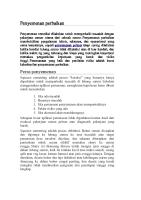
Fig. 1-Lab tests to measure casing/cement bonding characteristics. Test A3 measures axial loading strength. Test B3, C' and D' measure hydraulic bond. In test C, after cementing under controlled pressure, the casing is sawed off 10 check bonding. Test D, is a direct measure of cement/pipe adhesion strength in samples formed in a 7-inch mold.
kinds of damage such as fault shear, perforating tion, and joint loss while drilling ~ Drilling fluid selection and conditioning cement displacement efficiency and prevent pipe sticking during cementing, and
to improye differential
Discussions are illustrated by schematic drawings, curves, tabular data and photographs. An extensive reference list appears at the end of the article. Cement used in primary cementing is normally designed:
1. To support the axial load of the casing string and strings to be run later 2. To seal intended production or injection intervals from overlying or underlying permeable sections (zone isolation) 3. To protect the casing from damage or failure, and the productive
AXIAL LOAD SUPPORT High axial loads may be imposed on the casing string and/or surrounding cement by landing and suspension methods and later operations. And the cement strength 6
Based on these worst-case results, Bearden and Lane2 provided a relationship for determining support capability of a cement sheath, conservatively utilizing results for mud-wetted and non-displaced co ndi tions. ModHying their relationship to utilize compressive strength (assumed to be 10 times tensile strength), gives the formula: F=O.969
ScdH,
Where: F Sc d H
deforma-
~ Common causes of casing failure that can adversely affect the cement job as well as future operations, including mill defects appearing in new pipe.
4. To support the borehole through interval.
required to support such axial casing loads has been determined through shear bond testS.1,2.3 The axial load which breaks the cement bond has been measured with the test apparatus shown in Fig. 1(A) . In this test where the surface in question is the outer periphery of the inside pipe, the ability of cement to support axial casing loads was found to be proportional to the area of contact between cement and the casing. Therefore, support coefficient,2 shear bond3 or sliding resistance,4 as it is described by various investigators, is the load required to break the bond, divided by the surface area between cement and pipe. Shear bond strength increases with cement tensile or compressive strength as shown in Fig. 2.2 A fairly narrow range of shear bond at a given tensile strength resulted for various cement compostions tested. And a significant reduction in shear bond was caused by mud wetting of the pipe. Poorest results were obtained when the pipe was mud-wetted and no attempt was made to remove the mud film.
= = = =
force or load to break cement bond, pounds compressive strength, psi outside diameter of casing, inches height of cement column, feet.
For example: using
For one bonded
500 psi compressive
500 X 7 X 1 =
strength
foot of 7-inch casing, cement: F 0.969 X
=
3,390 pounds.
Required strength. The load to break the cement bond during hanging and drilling-out operations normally would not exceed weight of the casing string (such as surface pipe) plus miscellaneous loads (such as weight on bit when drilling out the shoe joint). Therefore, the load capacity noted above, 3,390 pounds per foot of cement column, provided by the relatively low compressive strength of 500 psi, should be more than adequate to handle anticipated axial loads. Thus, as this example indicates, the equation permits calculation of approximate load capacity for various pipe sizes and cement compressive strengths. Cement compositions normally can be formulated to rapidly develop adequate strength for casing landing loads. This allows drilling operations to proceed with little or no waiting-on-cement (WOC) time. Also, low strength "filler" cements, which are relatively inexpensive and of low density-and less likely to induce lost circulation when high cement columns are requiredmay have adequate compressive strength to meet axial load support requirements. In addition to water-based mud wetting of the pipewhich is allowed for in the above equation-other factors WORLD OIL
1977
that affect cement shear bond performance to axial load are:
with respect 350
. Casing collars, which increase the ability of the cement to support axial loads
'. Low water-to-cement ratios which increase slurry density and improve shear bond because of increased compressive strength, Fig. 3.4 . Radial loads imposed on cement and casing by the formation, which should increase shear bond due to the increased friction between pipe and cement
300\
~ 250,
ci
on the exterior
of the casing which
ffi
50
o o 50 100 150 200 250 300 CEMENTTENSILESTRENGTH,PSI
mud is not removed
such as increase coating because
. Raw cement characteristics, such as fineness of grind, may also affect shear bond strength . Cement contamination by mud which lowers shear bond appreciably, see Fig. 3. . Displacement mechanics and efficiency which affect thickness and continuity of the cement sheath around the casing, and . Pressure/temperature effects which can contract the casing diameter after the cement hardens. This factor will be discussed in a later article.
ZONE ISOLATION Although cement with a low compressive strength may be adequate to handle axial and rotational casing loads, high ultimate strength may be required for zone isolation and to support the borehole. Therefore, cement compositions should be selected which quickly provide adequate compressive strength for continued drilling operations but which also provide adequate strength, ultimately, for production operations. A comprehensive study of factors governing zone isolation under downhole conditions would be very complex. Zone isolation depends, in part, on load interactions between formation, cement and casing, some of which are not well understood. Further difficulty arises in determining type and magnitude of loads imposed by fluid injection pressures and temperatures, and production pressure drawdown and depletion. For these reasons, only qualitative judgements have been attempted in studies to date and these usually relate to the "hydraulic bond" which indicates adhesion between casing and cement, or between cement and formation. The actual relationship between hydraulic bond measured in the lab, and downhole zone isolation has not been reported, if such a determination has been made. Bonding test. Various investigators3,5,6 have measured hydraulic bond. Test arrangements are shown in Fig. 1(B) .3,6 and Fig. 1(C) 5 Pressure is applied to the exterior surface of the casing causing the casing to become 1977
Fig. 2-Effect of cement tensile strength and mud wetting on shear bond. Most cements fall in narrow range except
where
. Roughness of the exterior casing surface, rust or special resin-sand coatings, which can shear bond substantially6 (Normally such special would not be required for axial load support minimum shear bond strength is adequate)
WORLD OIL
:
is 200 , m a: 150
IU oJ W >
Fig. 46-Effect of fluid yield strength on velocity required to initiate flow in narrow side of eccentric annulus, for Bingham Plastic fluid with turbulent flow through annulus, see Fig. 40 (after McLean et al).'6
3.0,
MUD PLAST. VISC. = 10 10 YIELD PT. = 9.5 DENSITY, PPG = 5.5 DIA. HOLE, IN. = STANDOFF = 80%, 1 In.
2.8' 2.6
CEMENT 30 50 13.8
DISPLACEMENT RATE, RHEOLOGY DESIGN Generally, high displacement rates improve displacement efficiency if cement can be in turbulent flow up the annulus. Conditions that may prevent such flow include: Limited displacement rate capability (pumping equipment), a pressure window that limits displacement pressure and improper flow (rheological) properties of mud and/or slurry. Providing extra pumping equipment is basically an economic decision, if wellbore conditions can tolerate higher displacement pressures. Formation conditions that determine the pressure window are fixed, and attempts to exceed those pressure limits may create serious problems.
2.4' a: 0 lt) « u.. w ::E ::> ....J 0 > Ia]
2.2 2.0 1.8 1.6
::E
w t)
TOP ON NARROW SIDE I 3 10
I 5
I 10 -20
I 15 PUMP RATE. BPM 30
40
FRICTION PRESSURE LOSS FOR MUD, PSI/1,OOOFT.
Fig. 47- Type of curve that can be designed for individual conditions to determine additional cement, to assure coverage of the narrow side of eccentric annulus. Multiply volume factor times volume of annulus from shoe to desired cement column height. Example: At 5 bpm: To get cement to 1,000 feet above the shoe on the narrow side, requires 1.6 times the 1,OOO-foot annulus volume. Final cement top on wide side will be 2,200 feet above shoe. Note how volume factor decreases with higher pump rates (after Graham)."
mud contact in the annulus. Two bottom plugs may be required-one ahead, and one behind the spacer fluid-to prevent mud-cement contamination if: Contamination would create serious problems, and the spacer fluid does not by itself strip the mud film from the casing bore. A single bottom plug, ahead of the cement, will remove the film and accumulate mud ahead of the plug and behind the spacer fluid (see Fig. 7, Part 1). This accumulated mud then can contaminate the cement. A variety of spacer or preflush fluids are available, including water, brine, solutions of acid phosphates, die'Seloil (weighted or unweighted), oil base fluids and emulsions (oil in water, water in oil). Compatibility of both spacer and mud, and spacer and cement should be veriWORLD OIL
1977
Use of dispersants. The value of properly conditioned mud has been discussed. Fluid properties of the cement slurry can also be altered, i.e. dispersants can be added to lower gel strength to attain turbulent flow at lower displacement rates. This can be desirable where high pump rates would otherwise be required. By adding dispersant and lowering pump rate, an increase in effective contact time can be realized, along with the desired velocity profile. However, if turbulence can be achieved at reasonable pump rates without dispersants, the resulting displacement should be better, i.e. turbulent flow is better than laminar flow, but additional turbulence may not be "better yet." After turbulent flow is established, displacement efficiency increases with increased slurry flow resistance, as displacing drag forces increase with increasing contact pressure at the cement-mud interface. Thus, thinning the slurry to get "more" turbulence is not recommended. The buoyancy effect of higher density cement slurry on lower density mud is a controversy in the literature...,,,,,t28 Such effects should provide a positive displacing force on bypassed mud as long as there is vertical continuity of the mud column to the top of the rising cement-mud interface. Contact pressure at the base of the bypassed mudcement interface increases with increasing height of cement. This should increase both displacing pressure and erosional effects due to increased contact pressure near the bottom of the bypassed mud column. However, if the cement bypasses a portion of mud and then ree'Stablishes complete displacement of the movable mud in the annulus above the bypassed mud, displacing drag forces may be the only effective force working to remove the mud. With these conditions, it is likely that a large portion of the bypassed mud will not be removed unless turbulent cement flow is maintained. Sufficient contact time should be provided to allow the cement-mud 39
How to improve mud displacement primary cementing
drag forces to erode away any bypassed mud; a minimum of 10 minutes is recommended.97 How to utilize plug flow. When wellbore conditions are such that turbulence cannot be achieved, displacing with cement in a plug flow regime can maintain a flatter velocity profile in the annulus.127 While drag forces are not as effective as with turbulence, they can be maximized by increasing cement gel strength as high as possible, particularly in the lead part of the slurry. Also, cement density can improve plug flow displacement when it is maintained at least two pounds per gallon heavier than the mud.127 Centralized pipe and rotational movement may improve displacement efficiency. But reciprocal movement should be avoided, as intermittently increasing cement velocity could bypass mud. Pumping rates should produce annular rising velocity not greater than 90 feet per minute. Under some conditions this cannot be accomplished by controlling pump rate, i.e. with U-tube effect of higher density cement, and/or presence of lost circulation. How to improve laminar flow displacement. Wellbore and/or surface conditions that prohibit turbulent flow may al'So prohibit plug flow. When these not-uncommon circumstances exist, an alternative is to alter cement rheological properties to increase apparent slurry viscosity. Displacement, even in laminar flow can be effective if the slurry is thicker (has higher yield 'Strength and plastic viscosity) than the mud, and if sufficient volumes are used to obtain desired cement height on the narrow side of an eccentric annulus. 96,98 One guide for cement rheological design i'S to have cement yield strength exceed mud yield strength by a factor equal to maximum annulus clearance divided by minimum annulus clearance. Even though turbulence will not be achieved, the highest practical pump rate is recommended, as the difference between mud and cement velocities on the wide side vs. the narrow side is reduced as rate increases, Fig. 46. The cement volume used under these displacement conditions should be such that the final height of cement on the narrow side i'S above any zones to be protected. This volume can be determined from design curves based on specific mud and cement properties and casing-wellbore configurations (eccentricity), Fig. 47. This data should be derived from well site measurement'S of mud and cement slurry rheological properties and calipered hole size information. The detailed design curve determination is available in the literature.98 Coming next month: Primary cementing techniques, proper use of downhole and surface equipment.
LITERATURE CITED ... McLean, R. H., Manry, C. W. and Whitake~ W. K., Mechanics in Primary Cementing," JPT Vol. 1~, February 07Clark, C. R. and Carter, L. G., "Mud Displacement Slurries," JPT, Julr. 1973. .. Graham, H. L., 'Rheology-Balanced Cementing Improves cess," O&GJ, December 18, 1972.
40
"Displacement 1'967. with Cement Primary
Suc-
I.
Center
during
pipe in the borehole
2. Move casing during mud conditioning and cementing . Rotation is best for removing mud channels from narrow side of non-centered casing . Reciprocation aids in achieving turbulence. Do not use when displacing in plug flow . Combined rotation-reciprocation is most effective when displacing with turbulent flow 3. Know formation pressure limits in the wellbore . Lower limit is that required to maintain positive formation control . Upper limit is a function of the formation's strength, its resistance to hydraulic fracturing 4. Condition mud prior to cementing 5. Avoid adverse mud-cement reactions . Use proper spacer fluids or flushes and wiper plugs 6. Control displacement rates and slurry rheology . Use high rates where turb~lence can be maintained in the widest annular area, across interest zones . With turbulent flow, provide adequate contact time for mud removal . When turbulence cannot be developed and maintained, consider lower rates to achieve plug flow in narrowest annular areas, across interest zones . If neither condition can be attained, adjust cement properties to achieve high yield strength and plastic viscosity, displace at the highest practical rate and use sufficient volume to get desired height on narrow side of eccentric annulus 00Brown, R. W., et al, "Cement Rheology-A Tool for Better Completions," 1963. Petroleum Engineer Februa .00Howard, G. c. and Clark, 'J . B. "Factors to be Considered in Obtai'!inJ! Proper Cementing of Casing," API Drilling and Production Practice, 1948, I'p. 257-272. ... Dodge, D. W. and Metzner, A. B., "Turbulent Flow of Non-Newtonian Systems," AIChE Journal, Vol. 5, No.2, June 1959. ,., Robertson, R. E. and Stiffs, H. S., Jr. "An Imeroved Mathematical Model for Relating Shear Stress to Shear Rate in Drdling Fluids and Cement Slurries," SPEJ, February 1.976. '.3 "Standard Procedure for Testing Drilling Fluids," API RPI3B, Sixth Edition, April 1976. JOt"TestinJ! Oil Well Cements and Cement Additives," API RPI0B, Nineteenth Edition January 1-974. '00 Ror;ers, W. F., Composition and Properties of Oil Well Drilling Fluids, Third Edition 1963 Gulf Publishing Co., Houston. .06Ormsby, G. S., "Calculation and Control of Mud Pressures in Drilling and Completion Operations," API Drilling and Production Prac4ices, 1954, pp. 44-55. 107Brice, J. W., Jr., and Holmes, B. C., "Engineered Casi!,B. Cementing Programs Using Turbulent Flow ,Techniques," JPT, May 1964. ... Teplitz A. J. and Hassebrook, W. E., "An InvesJIgation of Oil-Well Cementing," API Drillinc_ and Production Practice, '\94ti, pp. 76-103. .00Burkhardt, J. A., "WeIlbore Pressure Surges Produced by Pipe Movement," JPT June 1961. 11.Holt "] , J. A., "Field Proven Techniques Improve Cementing Success," Worl 0./, August 1.976. m Barkis, B., "Primary Cementing, The Critical Period," B&W, Inc., Technical Literature. no Clarki E. H., Jr., "A Graphic View of Pressure Surges and Lost Circulation,' API Drilling and Production Practice 1956, pp. 424-438. m MacPherson, L. A. and Berry, L. N. "Prediction of Fracture Gradients from Log Derived Elastic Moduli," The Log Analyst, September 1972, pp. 12-19. u'Matthews, W. R. and Kelly J., "How to Predict Formation Pressure and Fracture Gradient from Eiectnc and Sonic Logs," Oil and Gas Journal, February 20, 1967 pp. 92-106. us EatonA B. A., "Fracture Gradient Prediction and Its Application in OilPT, October 11969pp. 1,353-1,360. field uperations," U6Taylor, D. B. an Smith, T. K., "improved Fracture Gradient Estimates in Offshore Drilling Operations," API Drilling and Production Practice 1970 pp. 41-50. m C~well, W. T., Jr., "Pressure Changes in Drilling Wells Caused by Pipe Movement," API Drilling and Production Praclices~ 1953, pp. 97:1112. U8Schuh F. J., "Computer Makes Surge Pressure Calculations Useful," O&G ] , August 3, 1964. .1>Bazer D. A. and Owen, H. B., Jr.!.. "Field Application and Results of Pipe ripping Nomographs," Paper SP~ 2656, 1969. ". Fontinot, J. E. and Clark R. K., "An Improved Method for Calculating Pressures in a Drilling Weh," Paper SPE 4521', presented at Fall Meeting, Las Vegas, Nev., September 3D-October 3, 1973. m Carney, L. L., "Cement Spacier Fluid," Paper SPE 4784, presented at Formauon Damage Symposium, New Orleans, La., February 7, 8, 1'974. I22Morris, E. F. and Modey, H. R., "Oil Base Spacer System for Use in Cementing Wells ContaimnJ! Oil Base Drilling Muds," Paper SPE 4610, presented at Fall Meeting, Las VeBas, Ne!'J September 30-0ctober 3, 1973. .23Beirute, R. M., "All Purpose Cement-Mud Spacer," Paper SPE 5691, presented at Formation Damage Control Symposium, Houston, January 29-30, 1976. ... "The Effects of Drilling-Mud Additives on Oil-Well Cements," API Bulletin D-4, Corrected Edition March 1963. .23Anderson, F. M., "Effect of Mud-Treating Chemicals on Oil-Well Cements, "O&GJ September 29, 1952. '28,Tschirley, N. k., "Cementing in Oil Muds," Petroleum Engineer, May 1975. Parker, P. N., eI al, "An Evaluation of a Primary Cementing ,Technique Using Low Displacement Rates," Paper SPE 1'234, presented at Fall Meeting, Denver, Colo., October 3-6, 1965. I28Garvin, T. and Slagle, K. A., "Scale Model Displacement Studies to Predict Flow Behavior DurinJlt Cementing," IPT, September 1911'. .
j
t
WORLD
Oil
1977
Cementing oil and gas.wells for downhole
Part 5-Guidelines
equipment use, stage cementing methods, new concepts for cementing large diameter casing George o. Suman, Jr., President,and Richard Ellis, Project Houston
Engineer,
Completion
Technology
C. Co.,
1 O-second summary Concepts and applications of cementing equipment used on casing strings during primary cementing are explained along with a discussion of stage cementing, mixing and density measuring devices, and how to cement large diameter casing by the stab-in method.
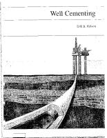
PREVIOUS ARTICLES in this series have presented the basic principles of hole preparation, casing handling, cement slurry chemistry and additive selection-and how mud is displaced by the cement slurry. This article will discuss downhole and surface equipment used in conventional primary cementing, with emphasis on the common problem of lost circulation. Special considerations for each of the casing strings-conductor, surface, intermediate and production-are reviewed and new ideas are presented for cementing large diameter casmg. Realizing that this subject covers a broad range of commercially available products and that design features of the equipment mentioned may vary widely among manufacturers, it is the intent of the authors to stress basic concepts and applications, and general precautions. Equipment used in conventional primary cementing normally includes a casing guide shoe, float collar, bottom and top wiper plugs, cementing head, centralizers, mixing equipment and pumps, Fig. 48.129,130,131Rotating or reciprocating type scratchers, multiple staging equipment, external
casing
packers,
metal
petal
baskets
and
/ or
other
specialized cementing equipment are frequently required. And, resin-sand coated casing, external casing seal rings and devices for increasing the annular velocity and/or swirling cement are sometimes applied.
TYPES OF SHOES, COLLARS In most cases, except in certain shallow wells, a roundnosed shoe is run on the bottom joint to guide the casing WORLD OIL
1977
past borehole irregularities encountered while running the string. Three types of shoes are commonly used: Guide shoes (without valves of any kind), float shoes and differential or automatic fill-up types, Fig. 49. Collars have basically the same features as shoes. They are commonly known as baffle collars (without valves), float collars, and differential or automatic fill-up collars, Fig. 49. Located one or more joints above the shoe, the collar, in addition to float and fill-up functions, acts as a seat for pump-down wiper plugs. It thus indicates when cement placement is complete, and controls the amount of cement left in the casing. Since cement immediately below the wiper plug may be contaminated, the collar should be positioned to minimize the amount of contaminated cement pumped out around the shoe. The guide shoe or baffle collar has an open bore somewhat smaller than pipe inside diameter. The float type contains a check valve which prevents backflow of cement into the casing after the cement job has been completed. This feature also prevents flow into the bottom of the casing during running. When float equipment is used, the casing rides or floats down to the desired depth because it is partially empty and somewhat buoyant. When using float shoes or collars, bouyancy is controlled by the amount of fluid placed inside the casing from a surface fill-up line. The casing is normally filled at regular intervals (say every five to 20 joints). Partial filling is also required to prevent collapse of large diameter casing. Differential/automatic fill-up shoes and collars provide partial fill-up of the casing during running, using either differential pressure, Fig. 49, or-for the automatic type-a predetermined-size orifice. Most single, differential fill-up units (shoe or collar) keep the casing about 90% full, unless the well's fluid level is low due to lost circulation. An additional differential fill-up unit results in about
81
%
fill-up.
Of
course,
neither
type
of "auto-
matic" fill-up equipment should be run in combination with float equipment. Pumping fluid through some types of "automatic" fill-up units converts them to conventional float valves. In other types, a ball is pumped through the tool for conversion, Fig. 50. This type preserves the "automatic" fill-up feature if attempts are made to break circulation during running. Differential fill-up equipment is frequently used on long 41
strings to: Reduce surge pressures by permitting part of the displaced mud to enter the casing, rather than all being forced up the annulus; to provide continuous
partial fill, thereby reducing running time, and to avoid the hazard of casing collapse. Some reasons for selecting float equipment without fill-up features are: · The casing can be filled with well-conditioned mud, and entry of extraneous materials from the borehole is avoided, i.e. shale cavings, cuttings and LCM.
. This equipment .is somewhat simpler in operation and, possibly, more reliable. · It gives more positive indications of wellbore fluid gains or losses; and it offers positive downhole casing shut-off if the well tries to kick.
PLUG CONTAINER
. There is a more or less continuous and progressive "breaking" of gelled mud in the borehole. Pressure surges causing formation fracturing and lost circulation can be prevented by limiting casing running speed. Running casing at speeds which provide annular flow rates acceptable during drilling is normally safe (see Fig. 43, Part 4). Surge pressure should be calculated to determine safe running speed where clearance between hole and casing is small (Part 4). Other considerations in establishing running speed include: Presence of bridges or key seats or doglegs; proximity of the shoe to total depth, and, occasionally, the number of scratchers and centralizers. If there is lost circulation material in the mud system, "automatic" fill-up equipment should not be used. And if use of lost circulation material in the slurry is planned, bottom wiper plugs and float equipment-perhaps with the exception of flapper valve types with straight-through openings-may have to be avoided. As an extra precaution to supplement visual tool inspection, fluid can be pumped through float and fill-up equipment after make-up to verify operation before running to bottom. Following cement placement-and after bumping the top plug-the pressure normally is released. This release should be rapid, to activate the check valve. If backflow is observed, pressure must be maintained until the cement sets up. However, excessive internal pressure expands the casing and it can contract and form a micro-annulus when the pressure is released-after the cement sets (see Part 1). Float, baffle and fill-up collars are normally made with equal or greater burst and collapse strength than the casing on which they are run. For shoes, however, these design criteria are not generally considered critical, as high burst and collapse strength is not required at this location in the string after drill-out.
FLOAT COLLAR
CENTRAUZER
GUIDE SHOE
PUMPING CEMENT
Fig. 48-Main equipment components of a typical primary cement job in a moderate depth well where additional accessories such as scratchers, stage collars, etc. are not required.
42
WIPER PLUGS, CEMENTING HEADS Wiper plugs are used to separate the cement from preceding or following fluids, Fig. 51. The bottom plug also removes mud from the wall of the casing, and prevents this mud from accummulating beneath the top plug and being deposited around the lower casing joints (Part 1) . After reaching bottom, the diaphragm in the bottom plug ruptures and cement is displaced out the bottom of the pipe and around the casing. The top plug seats on WORLD OIL
1977
the bottom plug or float collar, after being displaced bottom, and shuts off flow.
to
Cementing heads are available which hold one or more plugs. When the two-plug system is used, the operator should verify that the bottom plug is, in fact, placed in the bottom position in the cementing head. A mechanical device should be used to give visual proof when the top plug leaves the head. The cementing manifold should be connected so that the plug can be pumped out of the cementing head with the displacing fluid. If the cementing head is located far out of reach, delays may be encountered in releasing the top plug and pumping may be interrupted for a period of time to the detriment of the operation. Pup joints may have to be used to keep the cementing head within reach so that such delays can be minimized. At this time the cement is usually falling down the casing on a vacuum. And displacing fluid can be siphoned into the casing below the top plug (before it is released) if the valve to the supply source is not kept closed. Since the fluid can be siphoned through the cementing pump, the valve should not be opened until the top plug has been released. Another precaution taken by some service companies is to pump a small volume of cement on top of the top plug before switching to displacing fluid. A bottom plug is not recommended with large amounts of lost circulation material in the slurry or with badly rusted or scaled casing, as such material may collect on the ruptured diaphragm. Displacement of the top plug should be carefully monitored. The volume of fluid behind the plug should be determined from calibrations on the cementing unit tanks or by measuring out of a mud storage tank. Another method is to count pump strokes and convert to volume by applying a known pump efficiency. If available, a flowmeter can be used to verify volumes pumped. Pumps should be slowed as the pre-calculated displacement volume is reached, to avoid sudden bumping of the top plug and excessive pressure. A mud line pop-off valve is a desirable safety precaution. If the top plug does not bump at the calculated volume (allowing for displacement fluid compressibility), displacement should be stopped. Accurate volume measurements can be important III trouble-shooting a problem cement job, as well as in keeping track of the location of the top plug. CENTRALIZERS Casing centralizers are used to: Improve displacement efficiency (Part 4) ; to prevent differential pressure sticking (Part 1), and to keep casing out of key seats. Two general types of centralizers are spring-bow and rigid. The spring-bow type has greater ability to provide stand-off where the borehole is enlarged. The rigid type provides more positive stand-off where borehole is togauge. Special close-tolerance centralizers may be used on liners. Important design considerations are: Positioning, method of installation and spacing. Centralizers should be positioned on casing: Through intervals requiring effective cementing; on casing adjacent to (and sometimes passing through) intervals where differential sticking is a hazard, and occasionally WORLD OIL
1977
GUIDE SHOE OR BAFFLE COLLAR FLOAT SHOE (COLLAR)
DIFFERENTIAL FILL-UP. CIRCULATING TYPE
FLAPPER TYPE FLOAT
AUTOMATIC FILL-UP NON-CIRCULATING
INSERT FLOAT
Fig. 49-Examples of commonly used shoes and collars. Two fill-up devices are shown, the differential shoe or collar allows circulation while running pipe. With orifice type automatic fill-up device, high circulation rate shears the orifice retainer, converting tool to flapper type float. Insert float fits in casing collar recess between joints. (Courtesy Bakerline and Dowell)
on casmg passmg through dog-legs where key seats may exist. Effective cementing is important through production intervals and around the lower six joints of surface and intermediate casing strings-to minimize likelihood of joint loss. Particularly susceptible to differential pressure sticking are permeable zones where pressure is depleted and/or high mud overbalance pressure exists. Small clearance between casing and borehole, high deviation of the borehole and poor quality mud all increase differential sticking hazard (Part 1); proper centralization reduces the harmful effects of these conditions. Although centralizers may appear to be unnecessary obstructions on the pipe, they are effective and should be used where applicable. Correct positioning requires a caliper log of the wellbore so that locations correspond with to-gauge sections of the borehole. Installation method depends on type, i.e. solid body, split body or hinged. The hinged type is most commonly installed. Centralizers are held in their relative casing either by the casing collars or collars, Fig. 52. The restraining device collar) should always be located within type centralizer so the centralizer will pushed-into the hole. Therefore, the centralizer should not be allowed to casing joint. API has established
specifications
position on the mechanical stop (collar or stop the bow-spring be pulled-not bow-spring type ride free on a
for casing central43
FLAPPER VALVE SHEAR SLEEVE
SHEAR SCREW SHEARED
SHEAR SCREW VALVE SLEEVE FLAPPER VALVE RUNNING IN, VALVE OPEN (FILLING)
KIRKSITE BALL
~
BACK-PRESSURE VALVE RELEASED FOR CEMENTING
CIRCULATING
Fig. 50-Principle of differential fill-up operation. Pressure area differential on valve sleeve favoring the inside makes it engage lower flapper when casing is 90% full. Circulation has no effect on tool, center, until dropped ball shears the second sleeve, permanently releasing the upper flapper, right. DIAPHRAGM
Restoring force is the force exerted by a centralizer against the borehole to keep the pipe away from the wall. Centralizer restoring force capacity is determined through API test procedures and can be presented as a loaddeflection curve, Fig. 52.133 The minimum API restoring force must equal 2 (w) sin 30 degrees-where (w) equals weight of 40 feet of medium 'Weight casing and 30 degrees represents an average hole angle-at a casing to borehole stand-off 0.67 times average casing to borehole clearance. The factor (2) compensates for doglegs and is not applied for casing sizes from 10%-20-inch. Centralizer spacing. Load-deflection curves may be used for determining spacing required to achieve desired stand-off. And it should be noted that stand-off required to prevent differential pressure sticking will normally be less than that to properly centralize casing for good displacement efficiency. The lateral load imposed on a casing centralizer is the combined effect of centralizer spacing, casing weight, hole angle, weight of casing below the centralizer and dogleg (even though minor). The equation is: Lateral
component
CAST ALUMINUM INSERT
BOTTOM PLUG
51-Top
= Steel
angle,
degrees
When a dogleg exists between centralizers, expressed in degrees per 100 feet, then
1'h
8=
1'14
'h 400
Dogleg (degrees/IOO ft.) x Spacing (ft.) 200
T = ~ m' W . L. cos e for casing sections below the centralizer (the weight of the casing in mud is a close approximation for hole angles below the centralizer of 25 degrees or less)
HOLE SIZE, 9'12" 800 1,200 1,600 2pOO2~00
RESTORING FORCE, LBS.
. -- -
Fig.52-Example of spring-bow centralizer contained by stop collar so that device is pulled into hole. Load-deflection curve for a centralizer gives lateral force on casing at various deflections. For the example curve shown''', it takes over 1,700 pounds to move the casing V4 inch off center. izers, covering specific hole sizes and casing sizes and weight.132 Starting force, permanent set and restoring force are defined and specified for individual sets of conditions. Starting force is the force required to start the centralizer into previously run casing, as determined by API test. The maximum starting force permitted is less than the weight of 40 feet of medium weight casing on which the centralizer is run. Permanent set is the constant bow height of the bowsprings after each bow-spring has been flattened 12 times. Maximum starting force is determined before permanent set-restoring force after.
44
tension
=
o c z o o
Fig. 82-Example
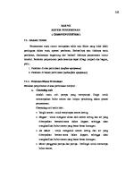
of a cement bond log display of a section of well-bonded casing shows typical data included on field log. Amplitude-time display (right) indicates weak pipe amplitude signal (grey tone left half) and strong formation signal (black line right half) comparable to signal B in Fig. 81 (courtesy Welex).
WORLD OIL
1977
Acoustical cement bond logging in use since 1960, provides an evaluation of the cement column behind casing. The cement bond log (CBL) combined with an acoustic signature log (MSG, VDL, XV, etc.) is a log in which both time of arrival and amplitude of vibrations are used to evaluate bonding conditions. Sonic signals are transmitted to a receiver that is acoustically isolated within a combination tool. In traversing through casing, signal amplitude is attem.\ated to a varying degree depending on material outside the casing. Attenuation effect will be greater if that material is solid and bonded to the casing. Signal amplitude is converted to electronic signals and varies inversely with degree of attenuation. Thus a high amplitude casing signal is indicative of no bond between cement and casing, Fig. 81 (A). When cement is firmly bonded to casing and formation, there is a low casing signal and the signal received is characteristic of formation behind pipe, Fig. 81 (B). When cement is bonded to pipe bu t not formation, both casing and formation signals have low amplitude, Fig. 81 (C). When casing is resting against the borehole, channeling commonly occurs, preventing cement from surrounding the casing. Thus casing is free on part of its circumference and formation-cement-casing coupling exists around the balance. Then both casing and formation signal are present as shown in Fig. 81 (D). It is important to receive more than just the casing signal. Acoustic signals travel through fluid in the wellbore, casing, cement and/or annular fluids and formation. The casing and formation signals are of primary interest. Additional details of CBL techniques, technology and procedures are available in the literature.184-196 eBL presentations.
Acoustic signals in a cased borehole consist of all arrivals along any coupled path between transmitter and receiver. The time and amplitude of the combined signal from the various paths are such that all information cannot be presented adequately by a normal logging curve. Thus a CBL usually includes an amplitude curve that measures a specific time segment of the acoustic signal and one or more of the following: . Transit time of the first acoustic signal that exceeds a predetermined amplitude 69
. Amplitude of the formation signal, and . A variable intensity recording where dark and light streaks represent positive and negative half cycles of the acoustic signal, or . An acoustic scope picture-XY presentation.
include a gamma ray curve and a casing collar log, Fig. 82. Though not directly related to acoustic properties measured by CBL, this information has proven helpful in CBL interpretation.
Additional measurements frequently included on CBLs
Interpretation. Validity of CBL interpretation is a controversial issue. There are no industry standards for tools or procedures. Inadequate information on CBL headings, miscalibration of tools, lack of effective tool centering in the casing and/or poor running procedures have resulted in misleading interpretations. Interpretation of a specific CBL depends on how and what portion of the acoustic signal is measured and recorded. Factors that significantly affect tool response include: Acoustic frequency of tool; electronic control that determines the acoustic signal segment measured (Gating systems and bias settings); spacing between transmitter and receiver; tool calibration; centralization, and logging speed. Here are other factors that can introduce errors in
1.5
en I-I o > ui c ::) I::::;
Q. ::E