![Conveyor Design Draft [PDF]](https://pdfs.asia/img/200x200/conveyor-design-draft.jpg)
15 0 165 KB
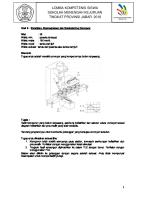
The values are not linked with anywhere…..
2 4 R= 40 m 3 7 6
5 10 m
CONVEYOR PROFILE
500 m
1
20 m
8
9
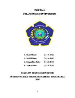
CONVEYOR DESIGN by IS - 11592 : 2000 Material
:
Coal Ash Bottom
Lump Type Lump Size Type
Uniform Size
Flowability / Material Characteristic
Average Flowing
Maximum Lump Size Capacity Bulk Density of Material
Sized, in permissible Range
:
300 mm 960 TPH 0.800 t/m3
C ρ
: :
: :
1200 mm
Lump Size Factor
B KL
Air Bone Factor
KAB
:
0
Abrasiveness Factor
KAS
:
2
Speed Factor Where, KV = ( KL + KAB + KAS )
KV
:
6
Belt Speed Angle of Inclination Angle of Surcharge
V δ ψ
: : :
Input Data & Calculation: Width of Belt
:
Angle of Repose Slope Factor Maximum Capacity of a Belt (for ρ=1.0 t/m3, V=1.0 m/s, K=1.00) Corresponding Values: Maximum Belt Capacity Trough Angle Belt Width Cross Sectional Area
K C
: :
C λ B A
: : : :
Selected Belt Width Actual Belt Speeds Belt Type
B V
: : :
As per IS 11592, Table 3
4
Over 35 and up to 40
3 m/s 14 ° 25 ° °
0.91 439.56 t/h
464 20 1200 0.129
As per IS 11592, Table 6 As per IS 8730, Table 3 As per IS 8730, Table1
t/h ° mm m2
1.2 meter 2.84 m/s Fabric Carcass Belt
As per IS 11592, Table 9
As per IS 11592, Table 10 As per IS 11592, Table 7
CONVEYOR DESIGN by IS - 11592 : 2000 TE
:
17822 N
R
:
2717 N
f L mc
: :
0.02 100 m
:
15 kg/m
Mass of revolving idler parts along the return side of the conveyor per meter
mr
:
15 kg/m
Mass of belt per meter Mass of handled material on conveyor per meter mG = 1000.ρ.Q / V
mB mG
: :
7.7285 kg/m 93.912 kg/m
δ
:
14 °
RS
:
2164 N
Ra
:
757.21 N
Volumetric Capacity Q= A.V.K
Q
:
0.3333 m3/s
Handled material conveying speed component in the direction of belt motion
V0
:
Rska
:
258.38 N
Interskirt Plate Width
b1
:
0.8 m
Acceleration length in loading area
la
:
0.7648 m
μ1
:
0.6
μ2
:
0.5
Rw
:
610.47 N
Peripheral Force on the Drive Pulley TE = (R + RS + RSP1 + RSP2 + RSL) Main Resistance R = f . L . g. [ mc + mr + (2 mB + mG). Cosδ] Artificial friction coefficient Conveyor length (distance between centers) Mass of revolving idler parts along the carrying side of the conveyor per meter
Slope angle of conveyor from horizontal line in the moving direction
Secondary Resistance RS = Ra + Rska + Rw + Rb Inertial and frictional resistance at the loading point and in the acceleration area between the Handled material and the belt Ra = Q . 1000 . ρ . ( V - V0 )
Frictional resistance between handled material and the skirt plates in the acceleration area Rska =
0 m/s
μ2.Q2.1000ρ.g.la (V+V0) 2 .b12 2
V -V 2
la =
2 0
2.g.μ1
Coefficient of friction between material and belt Coefficient of friction between material and skirt plate Wrap Resistance between belt and pulley
Rw = 9B 140+0.01.
Rw = 12B 200+0.01.
Tav
t
B
D
Tav
t
B
D
Average Belt Tension in the Pulley Belt thickness
not to be calculated for drive pulley
for fabric carcass belt
for steel cord belt
Tav t
: :
17115 N 0.1 m
3E-005
Pulley Bearing Resistance
Rb
:
d Rb=0.005 Rv D d : Shaft diameter inside diameter D : Pulley diameter R : Vectorial sum of the two belt tensions v acting on the pulley and of the forces due to the mass of the revolving parts of the pulley Rsp Special Resitance : Rsp = (Rsp1+Rsp2) = (Ri + Rsk + Rbc + Rp ) Resistance due to idler tilting Ri = g.Ci.μ0.Li (mB+mG) cos δ. sin i
Ri
:
537.53 N
not to be calculated for driving pulley
0.15 m 0.5 m 35835 N
1E-010
1886 N 1.5099 N
In case of carrying idlers equipped with three equ
A constant
Ci
:
0.5
coefficient of friction between carrying idlers and belts Angle of tilt of the idler axis with respect to a plane perpendicular to the longitudinal axis of the belt
μ0
:
0.35
i
:
2°
Length of installation equipped with tilted idler
Li
:
0.5 m
Resistance due to friction between Handled material and skirt plates
Rsk
:
84.491 N
lsk
:
1m
Rbc
:
0.048 N
Area of contact between belt and belt cleaner
Al
:
0.1 m2
Coefficient of friction between belt and belt cleaner
μ3
:
0.6
Rp
:
1800 N
Ka RSL
: :
H
:
Rsk =
μ2.Q2.1000ρ.g.lsk V2 b 1 2
Length of installation equipped with skirt plates excluding Frictional resistance due to belt cleaners Rbc = Al . ρ . μ3
Resistance due to friction at the discharge plough
Rp = B . K a Scraping factor Slope Resistance RSL = mG.H.g Lift of conveyor between loading end and dicharge end
: : : : : : : : : : : : : : :
1500 N/m 11055 N 12 m
: :
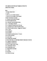
CONVEYOR DESIGN by IS - 11592 : 2000 Φ T1
T2
30⁰ TE
TE
:
17822 N
T2min
:
8204.12 N
TE max
:
21386.38 N
ξ μ Φ
: : :
Minimum Tensile force to limit the Belt Sag(Carrying Side) Pc (mB+mG) g Tmin≥ 8S
Tmin
:
5191.077 N
Pitch of carrier idler or idler spacing on carrying side of the conveyor Minimum Tensile force to limit the Belt Sag(Return Side) P .m .g Tmin≥ r B 8S
Pc
:
1m
Tmin
:
592.0756 N
Peripheral Force on the Drive Pulley Minimum Slack Side Tensile T2 min≥ TE max
1 eμΦ - 1
Maximum Peripheral Force TE max= ξ . TE Drive Coefficient Coefficient of friction between drive pulley and belt Angle of Wrap
1.2 0.35 3.67 radian
Pr Pitch of return idler or idler spacing on return : 1.5 side of conveyor Maximum Allowable Belt Sag S : 0.024 h S= a adm Minimum Force required in slack side T2 : 8204.12 Tension of Tight Side T1 : 26026.11 Average Belt Tension at the pulley Tavg : 17115.11 Vectorial sum of the two belt tensions acting on the Rv : 35835 pulley and of the force due to the mass of the revolving parts of the pulley ={ (T1 * cos(δ) + T2 * Cos (Ѳ) )2 +(T1 * sin(δ) + T2 * sin (Ѳ) + W p )2 }1/2
Weight of Pulley
Maximum Operating Belt Tension Tmax = T1 = TE
ξ -1 eμΦ - 1
m
N N N N
δ Ѳ Wp
: : :
14 ⁰ 30 ⁰ 5000 N
Tmax
:
-9617.87 N
See IS-11592, Table 15 See IS-11592, Table 16 210 °
:
Table 3: Maximum Lumps Sizes in relation to Belt Width
Belt Width 300 400 450 500 600 650 750 800 900 1000 1050 1200 1350 1400 1500 1600 1800 2000
Maximum Lump Size Uniform Size 75 75 75 100 125 125 180 180 200 260 280 360 380 380 410 410 460 500
Unsized 100 100 125 150 200 230 300 330 380 430 460 530 660 680 750 800 900 1020
Table 4: Lump Size Factor 6 4 Material Fine Grain to dust Granular Sized and Unsized
1 2 3 4 5 6 7 8 9 10 11 12 13 14 15 16 17 18
0
Lump Size
Lump Size Factor
Air Bone Factor