![Counterfort Abutment [PDF]](https://pdfs.asia/img/200x200/counterfort-abutment.jpg)
13 0 145 KB
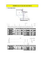
SALIENT FEATURES OF THE BRIDGE : Span c/c of brg. c/L of brg. c/L of exp. J Exp. Gap Overall span skew Depth of super-structure Wearing Coat thickness Depth of Bearing + Pedestal (minimum)
= = = = = = = =
Overall carriageway width Clear carriageway width Cross Camber Lenth of Abutment MATERIAL USED & THERE PROPERTIES : CONCRETE Grade of Concrete Mean value of concrete compressive strength Design Concrete compressive strength
fck fcm fcd
Secant Modulus of Elasticity Mean axial tensile strength
Ecm fctm
33.44 0.780 100.000 34.9 0 2.425 53 350
= = = =
m m mm m deg m mm mm
25 m 24 m 2.50% 30 m
= = = = = =
M 35 45 0.447 15.63 32308.25 3.46
Mpa Mpa *fck MPa MPa Mpa
= = = =
Fe 500 0.870 434.8 200000
Mpa *fyk Mpa Mpa
REINFORCING STEEL Grade of Reinforcement Design yield strength of reinforcement
fyk fyd
Modulus of Elasticity
Es
RCC Density
3 2.5 t/m
=
ANALYSES ASSUMPTION Enviromental parameters Relative humidity Exposure condition Modulus of Elasticity for Concrete For short Term loading For long Term loading f = Creep coefficent Creep coefficent for Foundation
Ecm Ecm'
= =
60 % Moderate
= =
32308.25 Mpa Ecm/ (1+f)
f
=
1 ( As ho = ¥ , For foundations)
Ecm'
=
16154.125 Mpa
Ac
= = = = = = @ =
0.00 0.00 #DIV/0! 90 25550 1.45 1.59 12463.4
Creep for abutment shaft Cross-sectional Area Perimeter in contact with atmosphere u Notational size ho Age of concrete at the time of loading to t¥ considered
2Ac/u
f (¥,90) Ecm'
m2 m mm days days (Refer Appendix B) *(Increased by 10% on the conservative side) 2 N/mm
SERVICEABILITY LIMIT STATE : Max permissible Stress in Concrete Rare Combination Quasi permanent Combination
= =
0.48*fck 0.36*fck
= =
16.8 Mpa 12.6 Mpa
Max permissible Stress in Steel
=
0.8*fyk
=
400 Mpa
Permissible crack width
wk,max
=
0.3 mm
Backfill Soil Parameter f d dsubmerged=
= =
i gdry
30 20.00 10.00
o
Angle of internal friction, Angle of friction between soil and concrete 1/2 d dry
= = =
= =
Surcharge angle Dry density of earth
= =
gsat
=
Saturated density of earth
=
0o 3 2.2 t/m 3 2.2 t/m
gwater
=
water density
=
3 1 t/m
o o
gsub
= =
m
Submerged density of earth coeff. Of friction b/w footing base & earth
Live Load Surcharge : Equivelent to Live Load surcharge intensity q
1.2
m Earth Fill =
SEISMIC PARAMETER Seismic Zone Type of soil Zone factor Importance factor Response Reduction Factor, Rlong.
3
1 t/m 0.8
= =
2 2.64 t/m
= = = = =
Z I
II rocky #N/A 1.2 2.5
Response Reduction Factor, Rtrans.
=
1
Response Reduction Factor, Rvert.
=
2.5
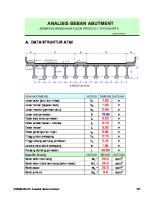
LEVEL DETAILS : Formation level Ground Level Bearing capacity
= = =
HFL level MSL
= = =
213.435 m 202.083 m 2 35.00 t/m 2 43.75 t/m 204.000 202.083 m
*/( Working State, Non-Seismic case) */( Working State, Seismic Case)
25.0 0.50
0
24.000
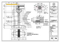
0.50 0.053 thick WC FRL : 213.435 2.5%
2.425
0.350 2.3
Cap Top :
3.4 c/c of girder Nos. of Girder C/c of Girder Top Flange Width
= = =
7 3.4 1
Nos. m m
Sign Convention : T MTT MLL
L
Y Showing +ve Force & Moment Direction Transverse Section of Structure 0.3 0.83
FRL :
213.435
Cap Top :
210.2945
HFL :
204.000
LWL :
202.083
GL
202.083
FDN:
197.083
0.57
1.7 0.5
16.352
1.43
0.27 0.6 11.7
5 Heel
Toe 5.0
1
A1/A2 210.2945
6
3 30
2.5
2.5
2.5
2.5
3
0.6
6
0.9 No. of CounterfortsEarth side Internal = External =
10.0 2.0
Nos. Nos.
0.9