![DIN 9830 - Burr Heights On Stamped Parts [PDF]](https://pdfs.asia/img/200x200/din-9830-burr-heights-on-stamped-parts.jpg)
5 0 753 KB
October 2011
D
DIN 9830 ICS 77.140.50
Supersedes DIN 9830:2010-01
Burr heights on stamped parts, English translation of DIN 9830:2011-10 Schnittgrathöhen an Stanzteilen, Englische Übersetzung von DIN 9830:2011-10
Normen-Download-Beuth-Steel Image Inc-KdNr.7923080-LfNr.7872778001-2017-02-28 08:43
Hauteurs de la bavure des pièces découpées, Traduction anglaise de DIN 9830:2011-10
Document comprises 6 pages
Translation by DIN-Sprachendienst. In case of doubt, the German-language original shall be considered authoritative.
©
No part of this translation may be reproduced without prior permission of DIN Deutsches Institut für Normung e. V., Berlin. Beuth Verlag GmbH, 10772 Berlin, Germany, has the exclusive right of sale for German Standards (DIN-Normen).
English price group 5 www.din.de www.beuth.de
!%(f[" 09.13
2056756
DIN 9830:2011-10
A comma is used as the decimal marker.
Contents Page
Normen-Download-Beuth-Steel Image Inc-KdNr.7923080-LfNr.7872778001-2017-02-28 08:43
Foreword ......................................................................................................................................................... 3 1
Scope ................................................................................................................................................. 4
2
Normative references ....................................................................................................................... 4
3
Terms and definitions ...................................................................................................................... 4
4
Formation of burrs ............................................................................................................................ 4
5
Burr heights....................................................................................................................................... 6
2
DIN 9830:2011-10
Foreword This standard has been prepared by Working Committee NA 026-00-03 AA Stanzteile of the Normenausschuss Federn, Stanzteile und Blechformteile (NAFS) (Springs, Stamped Parts and Moulded Parts Standards Committee). For more information on NAFS, visit our website at www.nafs.din.de. Attention is drawn to the possibility that some of the elements of this document may be the subject of patent rights. DIN shall not be held responsible for identifying any or all such patent rights. Amendments This standard differs from DIN 9830:2010-01 as follows: a)
Clause “Normative references” has been included;
b)
Clause “Terms and definitions” has been included;
c)
Figure 1 “Representation of the cut edge” has been included;
d)
Table 1 has been provided with a note;
e)
the standard has been editorially revised.
Previous editions
Normen-Download-Beuth-Steel Image Inc-KdNr.7923080-LfNr.7872778001-2017-02-28 08:43
DIN 9830: 1975-08, 1988-01, 2010-01
3
DIN 9830:2011-10
1
Scope
This standard is intended to provide manufacturers and users of stampings with an idea of the burr heights likely to be obtained. However, the values given in Table 1 are not permissible burr heights in the sense of tolerances for stampings, nor are they intended as a criterion for classification of cutting tools into quality classes. The data in Table 1 cannot therefore be regarded as substantial information for delivery conditions of cutting tools.
2
Normative references
The following referenced documents are indispensable for the application of this document. For dated references, only the edition cited applies. For undated references, the latest edition of the referenced document (including any amendments) applies. DIN 2192, Flat form springs — Quality requirements
3
Terms and definitions
For the purposes of this document, the following terms and definitions apply. 3.1 burr sharp-edged, usually thin, projection of material, forming during cutting, which can be loosely or firmly attached to a cut edge NOTE
This standard is concerned only with burrs forming due to shearing.
3.2 burr height maximum height of a burr on a cut part, where the flat surface of the workpiece in the immediate proximity of the burr serves as the reference surface
Normen-Download-Beuth-Steel Image Inc-KdNr.7923080-LfNr.7872778001-2017-02-28 08:43
4
Formation of burrs
Shearing is generally associated with the formation of a burr. The manufacturing of burr-free stampings generally requires the additional removal of the burr, e.g. by barrelling. Burr formation is mainly dependent on:
the thickness of the workpiece;
the tensile strength of the material being cut;
the clearance between punch and die;
the condition of the tool.
Burr formation increases with:
increasing thickness;
decreasing tensile strength;
increasing clearance between punch and die;
increasing tool wear.
4
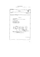
DIN 9830:2011-10
Figure 1 — Representation of the cut edge (notation)
Normen-Download-Beuth-Steel Image Inc-KdNr.7923080-LfNr.7872778001-2017-02-28 08:43
Key 1 2
Actual size: length or diameter Height of cut surface
3 4
Drawn-in band Cut band
5 6
Break band Burr height h
7
Thickness of workpiece s
5
DIN 9830:2011-10
Table 1 — Burr heights Tensile- Manufacturing strength precisiona of material MPa Up to
Workpiece thickness s mm
0.40
Over
0,40
Over
0,63
Over
up to
0,63
up to
1,00
up to
1,00
Over
1,60
Over
2,50
Over
4,00
Over
6,30
1,60
up to
2,50
up to
4,00
up to
6,30
up to
10,00
Up to
From
Up to
Burr height h µm From
over up to
100 250
250 400
400 630
630
–
Up to
From
Up to
From
Up to
From
Up to
From
Up to
From
Up to
From
f
20
50
30
80
30
120
40
170
50
250
70
360
100
600
140
950
m
30
70
40
110
40
170
50
250
70
370
100
540
150
900
210
1420
g
40
100
50
150
60
230
70
340
100
500
140
720
200
1200
250
1900
f
20
40
20
50
30
90
30
120
50
180
60
250
80
360
110
500
m
20
50
30
70
40
130
40
180
70
260
90
370
120
540
170
750
g
30
70
40
100
50
170
60
240
90
350
120
500
170
730
230
1000
f
20
30
20
40
30
50
30
70
40
110
50
200
70
220
90
320
m
20
40
30
50
40
70
40
110
60
160
70
300
100
330
130
480
g
30
50
40
70
50
100
60
150
80
220
100
400
140
450
180
650
f
10
20
10
20
20
30
30
40
40
60
50
90
60
130
70
170
m
10
20
20
30
30
40
40
60
50
90
70
130
80
190
100
260
g
20
30
30
40
40
50
60
80
70
120
90
180
110
260
130
350
For flat form springs, quality requirements as in DIN 2192 are to be taken into account. a
f fine, m medium, g coarse
Normen-Download-Beuth-Steel Image Inc-KdNr.7923080-LfNr.7872778001-2017-02-28 08:43
5
Burr heights
The burr heights given in Table 1 are empirical values. They are given as a function of workpiece thickness, tensile strength of the material being sheared and manufacturing precision. The latter is influenced by such factors as the clearance between punch and die, the precision of the machine tool and the tool, technological features, etc. Wear of the tool is taken into account by the fact that for each case (thickness of workpiece, tensile strength of the material being sheared and required manufacturing precision) a range is given for burr height. The higher values are to be expected with increasing tool wear. In cases where further requirements are specified for burr heights, e.g. for cut electrical metal sheets, these are to be agreed separately.
6