![DL24P Schematic Diagram [PDF]](https://pdfs.asia/img/200x200/dl24p-schematic-diagram.jpg)
10 0 1 MB
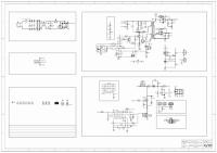
DL24P Load Tester Buffer Output to addition Power MOSFET current sources
Power Supply 8-12 vdc 12V
8-12 vdc
STPS41H100CG D1 A2
C7
Current Control 0v to 2.161v
PB1 PWM
R4
R5
10k
10k
R3 3.3k
C2
0.1uF
1
5
+
Vcc
-
Vee
U1
4
LM321
C3
3
0.1uF
Comps for PWM digital line not pulling to ground
0.1uF
R10
68k R12 3.3k
2
R13 150k
Current Control 0v to 0.100v
1 R6
0.1uF
100
uC DAC has only 6 bits so instead uses PWM timer for higher resolution control.
Integrator
C4
PWM filter 0v to 2.161v
R11 C5
0.1uF
100
HOT
100V 2x 20amps
3.3V
3
5
+
Vcc
-
Vee
Q1
1k
+ -
230 nC
C1
2.3 mA drive for 100 usec switch
0.1uF
3.3v Reg.
J5 1 2
V-
FAN
R1a 0.010
ME6203A-3.3V 3.3V U3 Vout 3 Vin C10 C11
V+
Fan+
2
Current Regulator Feedback 12V
R9
Q2
IRFP260 Q1 HOT
R2
4
R8 68k
R7 10k
(reverse protection) K
U2
LM321
A+
12V
A1
T NTC1 10k @ 25degC
R1b 0.010
2
Gnd 1
15uF
Out Monitor
A-
15uF
Current Shunt 0.005 ohms
A+ load MOSFET source
Current Sensing
Current Sensing
Current Sensing
0.1uF
3.3V
3.3V
4800 baud PD0 UART_Rx UART_Tx PD1 R25 1k
VC28 0.1uF
R26 1k
C24
C25
2.2uF
0.1uF
C31 0.1uF
R31 10k
TxD D2
V+
1 2 3 4 n.c. 5 6 7 8
R32 10k RxD D3
UART LED
U5
Gnd TxD RxD V3 UD+ UDXI XO
R27 150k
VBus +5v C32
16
Vcc R232_En 15 14 RTS_b 13 DTR_b 12 DCD_b RI_b 11 DSR_b 10 CTS_b 9
n.c. n.c. n.c. n.c. n.c. n.c. n.c.
0.1uF
3.3V
X2
C29 0.1uF
C33
PB1 PWM
SWD Programming/Debug DVcc Gnd SWDIO SWCLK RESET_b
1 2 3 4 5
C34
12.00 MHz
20pF
20pF
USB Micro Jack
U6 3.3V C43
C42
R41 10k
2.2uF
4.7uF
Reset_b C41 0.1uF
R42 10k
C44 0.1uF
test
1 2 3 4 5 6 7 8 9 10 11 12 13 14
VBus +5v DD+ n.c. ID GND
HC32F030E8PA (64K FLASH, 8K SRAM)
TSSOP28 package Boot0 VCAP1 PC14/32K_In SWCLK/PA14 PC15/32K_Out SWDIO/PA13 PA12 PD0 Tx (uses software ‘bit bang’ UART) 4800 baud PA11 PD1 Rx NRST USART1_RX/PA10 VDDA USART1_TX/PA9 PA8 PA0/ADC_IN0 DVcc PA1 ARM Cortex M0+ DVss PA2 Microcontroller PA3 PB2 PA4/SPI0_CS TIM6/PB1 PA5/SPI0_SCK PB0 PA6/SPI0_MISO SPI0_MOSI/PA7
28 27 26 25 24 23 22 21 20 19 18 17 16 15
R44 R45
120 120
- button
3.3V
3.3V
Setup button
Serial port / DFU programming DVcc Gnd RxD TxD Boot_b
R43 22k* Setup button SW1 - button SW2
U7
3.3V
JDY-23
n.c. 3 n.c. n.c. 4 Out1
R54
PA9/U1Tx PA10/U1Rx
Int5
Int4
t2 EIn
10
11
12
13
14
15
16
n.c.
n.c.
n.c.
n.c.
Int3 18 n.c. AL ED R52
9
n.c.
BT Status LED
R53 120
TxD 19
n.c.
D5
RxD 20
120
n.c. 7 Int7 t3 Ou n.c. 8
EInt1 21 n.c.
cc2541
6 Stat
R51 47
PwrC 22 n.c.
BlueTooth Module
n.c. 5 Out2
n.c.
120
D4
‘S4’ SD102AWS
Reset 23 n.c.
n.c.
Buzzer
R50
LCD
Start button SW4
Gnd 24
1 Vcc
n.c. 2 n.c.
Out6
Spkr1
PA06, SPI0_MISO 3.3v 3.3V 3.3v n.c. PA07, SPI0_MOSI PA04, SPI0_CS PB00, GPIO PA05, SPI0_SCK PC15 GPIO Gnd
1 2 3 4 5
Start button + button
Out7
R24 35k*
1 Osc_O Osc_I 16 n.c. 2 PF DVdd 15 14 3 n.c. DGnd QF 4 AVdd Rx/Rst_N 13 5 Ain2_P Tx 12 6 Ain2_N Ref_V 11 7 Ain2_P Ain3_N 10 8 Ain2_N Ain3_P 9 C23
UART to USB CH340G
VBus +5v
Int6
R23 42k*
20pF
t4 Out5
Ext Temp Thermistor 1 2 Gnd
NTC2 10k @ 25degC
15uF
0.1uF
C27
Ou
C21
C22
3.5798 MHz
20pF
Load Voltage Remote Sensing
J5
R21 100
C26
R22 10
0.1uF
Load Voltage Remote Sensing
X1
3.3V
C20
Fan Control
PC14
(Utility Smart Meter chip)
R20 100
Ext Temp Sensor
MOSFET Temp Sensor
PA00/ADC_IN1
RENERGY RN8209C Three input Sigma Delta ADC
17
47
D6 BT Active
+ button SW3
1 2 3 4 5