![Schematic Diagram (Rice Cooker) [PDF]](https://pdfs.asia/img/200x200/schematic-diagram-rice-cooker.jpg)
5 0 768 KB
SCHEMATIC DIAGRAM
WIRING DIAGRAM
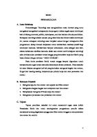
FUNCTION OF CENTER THERMOSTAT AND THERMALFUSE A. Center Thermostat The center thermostat senses when the bottom of the rice cooker pan reach 134°C ± 6°C. And it’s action turns off the cooking cycle, and starts the warming cycle.
Refer to these figures showing the center thermostat construction and cooking position. As the metal is heated, its ability to be attracted by the magnet decreases. Finally, the inner spring pressure becomes stronger than the magnetic pull and the metal and magnet will pop apart. The rod activates the switch lever which causes the auxiliary lever to press the micro-switch button into the warming cycle. B. Switch-On Preventive System
This is design to prevent the rice cooker from being turned on without the pan placed into position. 1) Normally when the pan is inserted properly into the rice cooker, the pan will depress the center thermostat. The center thermostat outer spring will be compressed. In this case when the switch button is depressed, the following will happen:
a. The auxiliary lever will release the micro-switch button. This puts the micro-switch in the cook position. b. The switch lever will push the rod which will allow the magnet to meet with the metal. c. When the rice is cooked and the proper temperature has been reached 134°C ± 6°C, the metal and magnet will pop apart as described in the center thermostat operation above. d. The rod will push the switch lever and cause the auxiliary lever to depress the microswitch button. This puts the micro-switch in the warming position. 2) When the pan is not in place within the rice cooker, the center thermostat is not depressed. a. In this condition, the outer spring is not compressed within the center thermostat preventing the metal from reaching its normal operating position. b. When the switch button is depressed, the switch lever and auxiliary lever work as above but the magnet cannot come in contact with the metal to hold the switch lever in the cook position. This happens because the switch lever hits the thermostat case and cannot push the rod, with the magnet attached, all they way up to meet with the metal. c. When the pressure is taken off the switch button, the switch lever releases immediately to the open or warm positions.
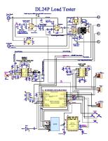
FUNCTION OF CENTER THERMOSTAT AND THERMALFUSE C. Thermal Fuse The thermal fuse is used to open the circuit to the cooking heater when the temperature has gone unusually high. This happens in cases such as incomplete contact between the heater and pan or if the switch buttons is forced to stay on keeping the heater energized abnormally. This fuse is not a resetting device and must be replaced after opening. Whenever replacing the fuse make sure the protective cover is placed over all exposed wiring. Cause of Fusion [A] Improper contract between heater and pan
[B] Forced application of current
TROUBLESHOOTING GUIDE When receiving the cooker to be repaired, be sure to always take charge
of
not
only
the
cooker body but also the pan and the lid, and ask for details as to the symptom
of
the
trouble.
Furthermore, when making troubleshooting of each part, be sure to remove the the socket.
power
plug
from
Disassemble and test a steamer: 1. Unplug the cooker from the electrical receptacle. If the appliance has a plug-in cord, remove it. 2. Remove the cover and the pan. 3. Turn the steamer over and remove the fasteners holding the base. 4. As needed, test the heating element, resistor, and service switch contacts (see below). Test a steamer heating element: 1. Disconnect the heating wire from one terminal. 2. Set the multimeter at RX1 (resistance times 1) scale to measure resistance. 3. Touch the tester probes to the two terminals. The heating element is okay if the meter reads near zero ohms. Test a steamer resistor: 1. Remove the lead to the heating element. 2. Set the multimeter at RX1 (resistance times 1) scale to measure resistance. 3. Touch the tester probes to the two terminals. The resistor is okay if the meter reads approximately 20 ohms. Test and service a steamer switch contact: 1. Press down on the lever arm to verify that the switch contacts make full contact. 2. If the switch does not make full contact, use a small file to file the contacts. 3. As needed, spray the contacts with electrical contact cleaner.