![14 Avanza / Xenia: Power Source Power Window [PDF]](https://pdfs.asia/img/200x200/14-avanza-xenia-power-source-power-window.jpg)
5 0 31 KB
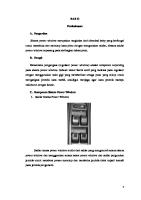
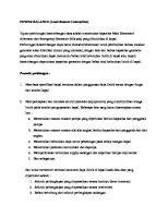
P o w e r S o u rc e
∗ 1 : From Aug. 2006 Production ∗ 2 : Before Aug. 2006 Production Indonesia M/T ∗ 3 : Before Aug. 2006 Production Except Indonesia M/T
P o w e r W in d o w
1
4
3
2 L–Y
P3 Power Window Regulator Master SW
1 ACC 1 AM1
IG1 2
3 IG1
IG
B–Y L–Y
2
Window Lock SW Up
I5 Ignition SW
Down
1
Power Window Control SW Front RH
Down
Power Window Control SW Rear RH
Up
2 ID2
L–Y
LG–B
1 ID2
Down
2
Power Window Control SW Rear LH
Up
Down
B–R
R
2
Up
Power Window Control SW Front LH
7. 5A IG1/BACK
R
PU
PD
RLU
RLD
RRU
RRD
11
7
12
5
4
2
3 V
B–Y
L–O
LG
R–Y
G–Y
L–R
P
1 IF1
3 IE1 3
8 IE1
2 IG1
5 IG1
1 IG1
4 IG1
L–Y L–O
L–Y
B–Y
V
BR
B
W–B
1
2
LG
L–Y
L–Y
L–Y
2
R–Y
2
G–Y
2
1
DD
8 W–B
40A AM1
40A IG1
1
DU
6
4
1
2
E
L–Y
2
5
IG Relay
1
1
2
L–Y
– 62 –
2
L–Y
B–R
R
2
7 BA1
3 BA1
8 BA1
7 BB1
3 BB1
8 BB1
2 5 IB1
2 IB1
1 IB1
2
Down
U 4
D 1 L–W
1
2
M
IC
M
M
Right Kick Panel
P4
P6
P7
Power Window Regulator Motor Front LH
Power Window Regulator Motor Rear LH
Power Window Regulator Motor Rear RH
P10 Power Window Regulator SW Rear RH
2 SD
L
L–W
2
V
1
5 3 B SU Up
Down
D
P9 Power Window Regulator SW Rear LH
1
B–Y
L–Y
V
Left Kick Panel
2
U 4 L
L–R
IA
W–B
EC
1
2 SD
W–B
J4 Junction Connector
BR
Left Fender Apron
D
P
BR(∗1, ∗3)
BR (∗2)
A
1
B–Y
U
5 3 B SU Up
Down
13 IE1 4
Battery
L–Y
2 SD
P8 Power Window Regulator SW Front LH
FL MAIN 2. 0L
5 3 B SU Up
2 B
R–Y
B
P5 Power Window Regulator Motor Front RH
G–Y
W–B
1
L–Y
30A (POWER)
1 1B
M
OVERALL ELECTRICAL WIRING DIAGRAM
14 AVANZA / XENIA