![AccurioPress C6100 C6085 Troubleshooting Guide Ver1.2 PDF [PDF]](https://pdfs.asia/img/200x200/accuriopress-c6100-c6085-troubleshooting-guide-ver12-pdf.jpg)
5 0 8 MB
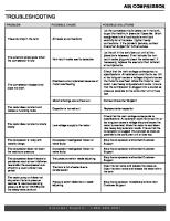
TROUBLESHOOTING GUIDE
2017.6 Ver.1.2
PP Support div.
KONICA MINOLTA Confidential
Table of contents 1. Image Quality 1.1 Spot 1.1.1 Cyclic white spot/black spot --------------------------------------------------------------------------- 4 1.1.2 White or color spots (fish eye) ------------------------------------------------------------------------ 5 1.1.3 Many white spots ----------------------------------------------------------------------------------------- 9 1.2 Line/band to feed direction (FD) 1.2.1 FD line due to photoconductor drum --------------------------------------------------------------- 10 1.2.2 Paper edge mark on fusing belt --------------------------------------------------------------------- 13 1.2.3 FD lines due to fusing separation claw ------------------------------------------------------------ 14 1.2.4 FD line due to intermediate transfer belt claw (Separation jam) -----------------------------16 1.2.5 FD gloss line due to the paper feed belt ----------------------------------------------------------- 18 1.2.6 Soilage at the edge after feeding smaller size --------------------------------------------------- 20 1.3 Line/band to cross direction (CD) 1.3.1 Line like ripple on image ------------------------------------------------------------------------------- 21 1.3.2 Lighter density band (drum humidity memory) /Darker Density band (NOx, Corona products, memory) --------------------------------------23 1.3.3 Thick paper trailing edge image abnormality ----------------------------------------------------- 26 1.3.4 CD line due to fusing belt ----------------------------------------------------------------------------- 28 1.3.5 Lines or banding on thick paper (shock noise) ---------------------------------------------------- 29 1.3.6 CD gloss line due to width of blank space -------------------------------------------------------- 33 1.3.7 Banding in developing roller cycle (44mm, uneven density) ----------------------------------35 1.4 Soilage 1.4.1 Toner contamination (spilling)/Toner scattering inside machine -----------------------------37 1.4.2 Background while printing high coverage --------------------------------------------------------- 40 1.4.3 Intermediate transfer belt cleaning failure --------------------------------------------------------- 41 1.5 Others 1.5.1 Rough image on thin coated paper ----------------------------------------------------------------- 43 1.5.2 Poor fusing (Toner peeling off) occurs at specific paper type --------------------------------44 1.5.3 Darker image at trailing edge/lighter at leading edge ------------------------------------------ 46 1.5.4 Uneven density at halftone/uneven gloss on thick paper ------------------------------------52 1.5.5 Fine line blurs at the leading edge ------------------------------------------------------------------ 55 1.5.6 Aslant banding (density difference) ----------------------------------------------------------------- 56 1.5.7 Wax attachment/Paper dust attachment ----------------------------------------------------------- 58 1.5.8 Highlight gradation changes daily ------------------------------------------------------------------- 61 1.5.9 Color change at continuous print -------------------------------------------------------------------- 62 1.5.10 Gloss memory ------------------------------------------------------------------------------------------ 63 1.5.11 Image density is lighter on uncoated paper ----------------------------------------------------- 65 1.5.12 Thin line is fainted ------------------------------------------------------------------------------------- 73 1.5.13 Image off centered in Cross Direction (main scan direction) --------------------------------76 1.5.14 Uneven gloss on thick paper ------------------------------------------------------------------------ 77 1.5.15 Photoconductor memory ----------------------------------------------------------------------------- 78 1.5.16 Uneven desnity like earthwormgloss ------------------------------------------------------------- 80 1.5.17 Wavy uneven density at the edge ---------------------------------------------------------------- 82 1.5.18 Emboss paper (textured paper) -------------------------------------------------------------------- 83 1.6 Troubleshooting by using CSRA 1.6.1 Darker/Lighter image density and background (CSRA approach) --------------------------85
-1-
KONICA MINOLTA Confidential
2. Paper Conveyance failure 2.1 Paper Conveyance 2.1.1 Paper wave / Paper curl ------------------------------------------------------------------------------- 89 2.1.2 Fusing wrapping jam ----------------------------------------------------------------------------------- 91 2.1.3 Vertical Conveyance jam (J-1619) and corner folded (dog ear) -------------------------------93 2.1.4 Light hitting mark at edge of thick paper ----------------------------------------------------------- 94 2.1.5 120 x 235 mm size envelope corner folding (dog ear) at the machine rear side ----------96 2.1.6 Image lacking for the max print size ----------------------------------------------------------------- 98 2.1.7 Paper wrinkle on the 2nd side ------------------------------------------------------------------------ 100 2.1.8 Separation failure at the 2nd transfer belt (J-3102/ Fusing wrinkle/corner folding at lead edge) ------------------------------------------------------ 102
2.2 Paper Pickup 2.2.1 Corner folding (dog ear) of small size paper ---------------------------------------------------- 104 2.2.2 Wrinkle at the trailing edge -------------------------------------------------------------------------- 105 2.2.3 Pickup jam clearance workflow -------------------------------------------------------------------- 106 2.2.4 Thick paper jam due to multi-feed ----------------------------------------------------------------- 126 2.2.5 J-1618/1620/1622 (PFU No feed jam as paper does not reach to PFU exit sensor) -- 127
2.3 Paper ejection 2.3.1 Paper stick with each other due to static electricity ------------------------------------------- 128 2.3.2 Static Sticking in Options ---------------------------------------------------------------------------- 132 2.4 Troubleshooting by using CSRA 2.4.1 J-16xx (CSRA approach) ----------------------------------------------------------------------------- 135
3. Machine Trouble 3.1 Control 3.1.1 Long waiting time for mixed media ---------------------------------------------------------------- 139 3.1.2 Dehumidifying indication and unable to start print -------------------------------------------- 141 3.2 Error Code 3.2.1 C-3xxx(Fusing related error) ------------------------------------------------------------------------ 142 3.2.2 C-2235/4641/4642/4643 (Density on front side lighter than back side) ------------------ 147 3.2.3 C-2211/2212/2213/2214 (Drum motor error) --------------------------------------------------- 149 3.3 Others 3.3.1 Fusing unit frame breaks ---------------------------------------------------------------------------- 150 3.3.2 Unable to pull out the process mount ------------------------------------------------------------ 153
4. Option Trouble 4.1 SD-513 4.1.1 Clamp door open/close issue ---------------------------------------------------------------------- 154 4.1.2 Entrance conveyance section JAM (wavy curl paper) --------------------------------------- 155 4.1.3 Booklet edge soilage (machine front side) ------------------------------------------------------ 156 4.1.4 4-stitch booklet fold line at trail edge ------------------------------------------------------------- 157 4.1.5 How to calculate Fore-edge trimming adjustment value ------------------------------------- 158 4.1.6 Fore-edge trimming section (corner) paper torn-up/cutting shortage --------------------- 160 4.2 FD-504 4.2.1 Slitter JAM/SC caused by inputting wrong Custom size ------------------------------------- 161 4.2.2 How to clear slitter scrap JAM --------------------------------------------------------------------- 163 4.3 TU-503 4.3.1 Booklet side soilage at clamping ------------------------------------------------------------------ 165 4.4 IQ-501
-2-
KONICA MINOLTA Confidential 4.4.1 IQ-501 Spot was detected.. message remains ------------------------------------------------ 166
-3-
KONICA MINOLTA Confidential
1.1.1. Cyclic white spot/black spot (1) Symptom White spot/black spot repeatedly occurs at a certain cycle. (2) Cause (a) Drum unit Approx. 251mm cycle in a single color (b) Developing unit Approx. 43.5mm cycle in a single color (c) Intermediate transfer belt Approx. 1066mm cycle. On A3 (420mm) simplex printing, the symptom occurs approx. every 3 sheets. (d) 2nd transfer belt Approx. 195mm cycle (e) 1st transfer roller Approx. 70mm cycle (f) 2nd transfer roller/Up Approx. 120mm cycle (g) 2nd transfer roller/Lw Approx. 120mm cycle (h) Intermediate transfer drive roller Approx. 120mm cycle (i) Fusing upper belt Approx. 377mm cycle. The symptom occurs on 1st side at simplex printing. (i) Heating Roller Approx. 182mm cycle. The symptom occurs on 1st side at simplex printing. (j) Fusing lower roller Approx. 220mm cycle. The symptom occurs on 1st side at duplex printing. (3) Solution 1. Print test patter No. 43. Specify what color has the problem. Access Service mode, press [Test Mode]→[Test Pattern Output Mode] Enter the following value [Test Pattern]: 43 [Gradation-Y]: 0 [Gradation-M]: 0 [Gradation-C]: 0 [Gradation-K]: 0 Press [Print Mode] then print on A3. 2. After specifying the problem parts, replace the subject parts. Table of contents
-4-
KONICA MINOLTA Confidential
1.1.2. White or color spots (fish eye) (1) Symptom •White spots At solid part, white spots with unsharpness outline appear. Especially, it is noticeable on the multi-color with high contrast like Y100% and K100%. •Color spots At solid part, the darker spots with unsharpness outline appear. (Color spots with a core forming line) A kind of color spots like following photo on right side appears. There is a core forming line in color spot. Due to that, the darker spots appear. (Note) For both color spots and white spots, usually the core spot is seen at the center.
White spots
Color spots
Color spots with a core forming line
(2) Cause •While pulling out/pushing back the process mount or ADU mount, the developer or toner clump falls down on the image creation process path and paper feed path •White spots Around the developer attaching to the image creation process path, the DU and intermediate transfer belt cannot contact well and toner is not transferred. •Color spots The toner transferred on the intermediate transfer belt slightly returns to the next color drum but the toner around the developer does not return.
White spots
Color spots Next color
-5-
KONICA MINOLTA Confidential (Color spots with a core forming line) When shaking a toner bottle in wrong way, the toner sometimes entered to the accordion part of toner bottle head. The toner in the accordion part is compressed when inserting the toner bottle to the machine. Then, the toner clump is made. When printing halftone image or others, the clump may appear as the spots with core forming line. (Close condition of toner bottle vent)
(Open condition of toner bottle vent)
(Cross-section diagram/Close)
(Cross-section diagram/Open)
The toner in accordion part is compressed
-6-
KONICA MINOLTA Confidential (3) Solution 1. Check and clean the soilage on the developing unit (especially the top cover of the developing unit and adjacent process mount), DU (especially top cover) and paper path. *Clean the following parts with every 350,000 interval (Replaced timing of drum unit) as service manual. A top cover of developer unit
Adjacent process mount
Drum stay (top cover)
2. To prevent the color spots with a core forming line, explain the customer (Operator) the correct procedure indicated in the product package. *As shown in the procedure on toner bottle package .
-7-
KONICA MINOLTA Confidential 3. If the improvement up to step 2 is not enough, change Front & Back Density setting (1st Transfer Y/M/C/K). [Utility/Counter]→[Administrator Setting]→[System Setting]→[Expert Adjustment]→[Process Adjustment]→[Front & Back Density] White spots: Change setting by every +5 and see the result. Color spots: Change setting by every -5 and see the result.
Table of contents
-8-
KONICA MINOLTA Confidential
1.1.3. Many white spots (1) Symptom Many white spots in φ 0.1mm to 1mm size appear on any color. The symptom tends to occur under following environment. •Side2 of duplex print •Low humidity •More occurrence on recycled and high quality paper than coated paper. (2) Cause When toner is transferred from intermediate transfer belt to the paper while the resistance on the paper is not even, abnormal discharge occurs at the nipping part of 2nd transfer. The toner at the abnormal discharged part is not transferred to the paper and white spots occur. (3) Solution 1. Change the 2nd Transfer Output Adj. setting to + value. depending on the problem occurring side.
Enter the value by 10 increments
• [Paper Setting]→[Change Set]→[Expert Adj.]→[2nd Transfer Output Adj. (Front)] • [Paper Setting]→[Change Set]→[Expert Adj.]→[2nd Transfer Output Adj. (Back)] Note: When the Expert Adj. is not indicated, change the DIPSW1-0 (To show Expert Adjustment in the Paper Setting) from “0” to “1” (Show).
2. When the paper is exposed to the low humid ambient air or left in the PFU, the occurrence tends to increase. In that case, use the paper just unpacked from the package. Table of contents
-9-
KONICA MINOLTA Confidential
1.2.1. FD line due to photoconductor drum (1) Symptom White line may occur due to cleaning failure of the drum unit The occurrence increases under high coverage, low humidity environment.
Feed direction
搬送方向
(2) Cause The lubricant material is not applied evenly on the drum unit. (3) Solution 1. Print image sample (test pattern No.43) and check on what color does symptom occur. Access [Service Mode], press [Test Mode]→[Test Pattern Output Mode]. Enter the following value [Test pattern]: 43 [Gradation-Y]: 0 [Gradation-M]: 0 [Gradation-C]: 0 [Gradation-K]: 0 Press [Print Mode] and print on A3. 2. Conduct charging corona unit cleaning mode. Select the target color from the following then press [Start] button to start adjustment. Service mode→[Process Adjustment]→[Drum Peculiarity Adj]→[Charging Cleaning]
Select the subject color and press Start button.
Note: Do not conduct the Charging Cleaning more than 4 times continuously. 3. After the end of the cleaning, print the image and check whether the symptom has been improved. Press [Print Mode] then print image on the A3 paper.
- 10 -
KONICA MINOLTA Confidential
After confirming the cleaning completes, press [Print Mode] button.
Note: At the print mode of Charge cleaning, YMCK mixed sample is printed. The test pattern No.53 can be also used to check the effect. (In case of Bk) Access Service Mode, press [Test Mode]→[Test Pattern Output Mode] [Test Pattern]: 53 [Gradation-Y]: 0 [Gradation-M]:0 [Gradation-C]:0 [Gradation-K]:120 Press [Print Mode] then print on A3. Note Enter the gradation for the subject color. 4. If the line does not disappear, conduct the Drum Refresh mode. After pressing both buttons one by one then returning to the normal screen, adjustment is conducted. [Adjustment]→[Execute Adjust Operation]→[Drum Refresh Mode] * Note: • Do not perform refresh mode for the brand new drum. Otherwise, the cleaning blade or the photoconductor drum may get damage because the lubricant on the drum may not be enough.
- 11 -
KONICA MINOLTA Confidential 5. For subject color, print test pattern No. 53 again and check if the symptom is improved. Enter the following value (In case of Bk) Press [Service Mode]→[Test Mode]→[Test Pattern Output Mode] [Test Pattern]: 53 [Gradation-Y]: 0 [Gradation-M]: 0 [Gradation-C]: 0 [Gradation-K]: 120 Press [Print Mode] then print on A3. * Note: Enter gradation for the subject color. 6. If still the line remains, replace the subject color drum unit. Table of contents
- 12 -
KONICA MINOLTA Confidential
1.2.2. Paper edge mark on fusing belt (1) Symptom When the current paper size is wider in main scan direction (CD) than previous job, the line in feed direction (FD) occurs at the location corresponding to the previous paper edge. The symptom also occurs for the EF-104 (a fusing unit for the envelope) (2) Cause The fusing belt surface gets rough. The roughened part appears as the difference of gloss and looks like line in FD. It tends to occur after printing on paper contains much paper dusts or thick paper which gives big stress to the fusing belt. (3) Solution 1. Conduct fusing refresh mode. When the following button is pressed then returned to the normal screen, the adjustment is executed automatically. [Adjustment]→[Execute Adjust Operation]→[Fusing Refresh Mode]
2. After conducting fusing refresh mode, print test pattern No.53 and check if the symptom is improved. Press [Service Mode]→[Test Mode]→[Test Pattern Output Mode] [Test Pattern]: 53 [Gradation-Y]: 0 [Gradation-M]: 0 [Gradation-C]: 0 [Gradation-K]: 255 Press [Print Mode] and print on A3. 3. If the improvement is not enough, conduct fusing refresh mode. [Adjustment]→[Execute Adjust Operation]→[Fusing Refresh Mode] Note When Fusing refresh mode is repeated too much, fine gloss lines may occur. is the twice.
So, the maximum
4. When the improvement up to step 3 is not enough, print the larger width paper than the width between the paper edge marks. After printing 50 sheets for duplex by using normal paper (rough surface paper is more effective than coated paper), check image quality and confirm the improvement. If improvement is not enough, print out again with same settings. Note When the thick paper or the envelope of the same size is fed continuously, try to conduct the fusing refresh mode in the certain interval. It will help to minimize the damage on the belt. In case of the 350g/m2 or heavier paper, 5kp interval to conduct fusing refresh mode is recommended. For the use of envelope, 30kp interval is recommended.
Table of contents
- 13 -
KONICA MINOLTA Confidential
1.2.3. FD lines due to fusing separation claw (1) Symptom When printing on thin paper with duplex setting, separation claw mark (lien in FD) may occurs on Side 1.
Feed direction
Approx. 35mm interval
(2) Cause When printing on thin paper (soft paper), the separation air let the paper be pressed by the separation claw, causing the scratching line on the Side1. (3) Solution 1. To reduce the temperature of the lower roller at the timing coated paper starts to enter the fusing unit, change the [Prior Paper Type] from "Others" to "Plain". [User Setting]→[Common Setting]→[Prior Paper Type] 2. Select [Weak] for [Fusing Air Separation Air level setting] to reduce air level. [Paper Setting]→[Change Set]→[Expert Adj.]→[Fusing Air Separation Air Level Setting]
Note ・When the Expert Adj. is not indicated, change the DIPSW1-0 (To show Expert adjustment in the Paper Setting) from ”0” to “1” (Show). ・The side effect of changing air level is as follows: ・Fusing separation failure as air level is decreased (When much toner is attached to the leading edge of the paper)
- 14 -
KONICA MINOLTA Confidential 3. Decrease the fusing temperature by 5 ºC step and check effect (Maximum -10 ºC) [Paper Setting]→[Change Set]→[Expert Adj.] ・[Fus. T-Belt Center Temp (Print)] ・[Fus. T-Belt Edge Temp (Print)] ・[L-Fus. PressRoller Center(Print)] Note: • When the temperature is reduced too much, "fusing under offset" (Toner is peeled off because fusing temperature is not enough) may occur. Print test pattern No. 53(1 sheet) in order to check if "fusing under offset" symptom occurs. Press [Service Mode]→[Test Mode]→[Test Pattern Output Mode] Enter the following value [Test Pattern]: 53 [Gradation-Y]: 0 [Gradation-M]: 255 [Gradation-C]: 0 [Gradation-K]: 255 Press [Print Mode] then print on customer's paper. Table of contents
- 15 -
KONICA MINOLTA Confidential
1.2.4. FD line due to intermediate transfer belt claw (Separation jam) (1) Symptom White line in feed direction (FD) occurs at halftone.
Feed direction
Approx. 85mm interval
(2) Cause When the leading edge passes the 2nd transfer unit, three claws of the intermediate transfer belt contact with the intermediate transfer belt. At that time, if too much stress is given, the intermediate transfer belt surface gets scratched or filming due to toner occurs. (3) Solution 1. On [Int. Transfer Separation], change the setting from “Auto” (Default) to “OFF”. [Paper Setting]→[Change Set]→[Expert Adj.]→[Int. Transfer Separation]
- 16 -
KONICA MINOLTA Confidential Note • When the Expert Adj. is not indicated, change the DIPSW1-0 (To show Expert adjustment in the Paper Setting) from “0” to “1” (Show). • When the intermediate transfer separation claw is always released, wrapping jam of thin paper may occur. If the operator does not aware the jam paper and recover the jam, the paper may enter to the intermediate transfer cleaning unit. • Even if the paper weight is 62gsm or over when the stiffness is low or very curled paper is used, separation failure may occur. In that case, set [Int. Transfer Separation] to ON and register the setting to the paper profile. [Paper Setting]→[Change Set]→[Process Adj.]→[Int. Transfer Separation] • The default setting of [Int. Transfer Separation] is “Auto”. The separation claw press/release status by the paper weight is as follows. Intermediate transfer separation claw pressed/released ON
Paper weight (gsm) 52-61 62-74 75-80 81-91 92-105 106-135 136-176 177-216 217-256 257-300 301-350 351-400
OFF
Table of contents
- 17 -
KONICA MINOLTA Confidential
1.2.5. FD gloss line due to the paper feed belt (1) Symptom The gloss lines in FD direction appears at the ± 61mm from the center of the coated paper. It tends to occur when the heavy coated paper is used. The gloss line is made by the friction between the surface of the paper and the edge of the paper feed belt at outside.
Center of paper
Distance between lines: 122mm (±61mm from paper center)
Does not occur at leading edge of paper
Feed Direction
(2) Cause When the PF-707m/711 feed belt suctions paper, the friction is generated between the belt and paper and friction mark is left on the paper. Left side view
Paper
Gap height: 5mm
- 18 -
KONICA MINOLTA Confidential (3) Solution 1. In the Expert Adjustment, change the suction air level of the paper suction fan. [Paper Setting]→[Change Set]→[ Expert Adj.]→[PFU Suction Level Setting] • [Weak]: Weaken the suction power of the paper suction fan. • [Auto]: Return to the default suction power. • [Strong]: Strengthen the suction power of the paper suction fan. Change the setting value to [Weak] direction by every – 3 step until the symptom is improved.
Note: ・When the Expert Adj. is not indicated, change the DIPSW1-0 (To show Expert adjustment in the Paper Setting) from ”0” to “1” (Show). ・When the PFU Suction Air level is set too weak, the paper is not suctioned enough and pick-up jam may occur. ・ When the jam occurs after changing the setting to [Weak], move the upper sensor position adjustment lever to upward to fix the air outlet position.
Table of contents
- 19 -
KONICA MINOLTA Confidential
1.2.6. Soilage at the edge after feeding smaller size (1) Symptom When the paper size of the current job is larger in the cross direction (main scan direction) than previous job, the soilage appears at the non-image area of the previous job. (2) Cause During large volume printing of small size paper, slight amount of the toner and paper dust attaches to the surface of the fusing belt then accumulates. It attaches to the large size paper and appears as the soilage.
At non-image area of the fusing belt surface, the toner and paper dust attaches. Photo shows the case after feeding 500k of the same size continuously.
(3) Solution Print the single color solid on the large size by 5 sheets and check if the symptom improves. not, repeat the print. Note: When the 2 or more color solid is printed repeatedly, the fusing separation problem may occur. Also the blank sheet has less cleaning effect. So, single color solid is recommended. Table of contents
- 20 -
If
KONICA MINOLTA Confidential
1.3.1. Line like ripple on image (1) Symptom Unevenness in the main scan direction (CD) in upstream color occurs on solid image of secondary color (or more).
Feed Direction
(2) Cause •When toner charge is increased under the low humidity environment, the leak occurs at the 1st transfer section. •When the density is high at the solid secondary color section, the leak occurs at the 1st transfer section (3) Solution 1. Perform the gamma automatic adjustment [Service]→[Process Adjustment]→[Drum Adjustment]
Peculiarity
Adjustment]→[Gamma
Automatic
2. Change the Neutralizing Output (Dis-Elec. Output) setting from [Standard] to [Condition 1]. and check the image. (Check the image with symptom) [Utility/Counter]→[Administrator Setting]→[System Setting]→[Expert Adjustment]→[Process Adjustment]→[1st Trans. Dis-Elec. Output]
3. If the symptom is not improved by performing the step 2, set the [1st Trans. Dis-Elec. Output] back to [Standard].
- 21 -
KONICA MINOLTA Confidential 4. On [Front & Back Setting], change the 1st transfer current setting by 5 steps increments for the subject color then check the image. [Utility/Counter]→[Administrator Setting]→[System Setting]→[Expert Adjustment]→[Process Adjustment]→[Front & Back Setting]
Note • When this method failed to improve the symptom, try adjusting by decreasing it. • As changing the 1st transfer current, photo conductor memory may occur (image remains at 251mm interval). If this symptom is confirmed, change the [Dis-elec. Pole Output] to [Condition 2]. [Utility/Counter]→[Administrator Setting]→[System Setting]→[Expert Setting]→[Process Adjustment]→[1st Trans. Dis-Elec. Output] 5. After performing the above steps 1 to 4, and still the symptom is not improved, reset the [Front & Back Setting] to 0 which was changed at step 4. Based on the color produced, and decrease the maximum density of single color by -2 steps and check if the symptom is improved [Utility/Counter]→[Administrator Setting]→[System Setting]→[Expert Adjustment]→[Process Adjustment]→[Maximum Density Adjustment]
Table of contents
- 22 -
KONICA MINOLTA Confidential
1.3.2 Lighter density band (drum humidity memory)/Darker Density band (NOx, Corona products, memory) (1) Symptom 1) Drum humidity memory In main scan direction (CD), approx. 37mm width lighter density band appears at approx. 251mm interval. The width of the band corresponds with the distance between blades. Approx. 37mm Approx. 251mm
Paper feed direction
2) NOx (Corona products) memory In main scan direction (CD), darker density band appears at approx. 251mm interval. The density change point is clear at leading edge side and it gradually disappears at the trailing edge side. Once the symptom occurs, it continues 2 to 3 days. Approx. 251mm
Paper feed direction
(2) Cause 1) Drum humidity memory Transfer ability (developing ability) deteriorates in the cycle of drum rotation if there is a humidity difference on the drum surface between the transfer belt side and the write unit side. It tends to occur on first copies after machine is switched ON in the morning. 2) NOx (Corona products) memory When the corona products, NOx, stays long period around the drum unit, the NOx enters to the photoconductor layer of the drum and changes the drum potential. Consequently, it causes darker density band in drum cycle. The symptom tends to occur if the power switch of the machine is turned OFF just after printing and kept turn OFF for several days (more than 4 days). The effect remains until the NOx in the photoconductor layer disappears.
- 23 -
KONICA MINOLTA Confidential (3) Solution 1) Drum humidity memory 1. From the service mode or Utility menu, perform the automatic gamma adjustment then check whether the symptom is improved. (Repeat several times and check the result) [Service]→[Process Adjustment]→[Drum Peculiarity Adj.]→[Gamma Automatic Adjustment] [Utility/Counter]→[Administrator Setting]→[System Setting]→[Expert Adjustment]→ [Execute Adjust Operation]→[Gamma Automatic Adj.] 2. To prevent future occurrence, change photoconductor drum small rotation interval shorter. Change the setting from 3 minutes (Default) to 1 minute. If the effect is not enough, select much shorter setting (30 sec to 10 sec) [Service]→[Process Adjustment]→[Interval/Quantity Adj.]→[Drum Small Rotation Interval] * Note:
Photoconductor life gets shorter.
2) NOx (Corona products) memory 1. It is difficult to let the NOx go out from the photoconductor layer. Therefore, it is difficult to take action once the symptom occurs. Therefore, remove NOx from drum before turning OFF the power switch of the machine. [Solution 1] Request customer to turn OFF the power switch after 1hour from the last print. (The longer, the more effective.) Auto shut off function may be helpful: Set auto shut off to 1hour or longer. [Utility/Counter]→[User Setting]→[System Setting]→[Power Save Setting]→[Power Save Function Setting]→[Auto Shut Off]
- 24 -
KONICA MINOLTA Confidential
[Solution 2] To shorten the time, pull out the process mount and remove the intermediate transfer unit and ventilate the DU neutralization corona to remove NOx products. Note: Minimize the light exposure of the DU. Take action quickly. Table of contents
- 25 -
KONICA MINOLTA Confidential
1.3.3. Thick paper trailing edge image abnormality (1) Symptom Image abnormality occurs around 6 mm from the trailing edge of thick paper.
Paper feeding direction
(2) Cause When the trailing edge of paper pushes up the intermediate transfer belt, the 2nd transfer roller /Lw's winding section of the intermediate transfer belt changes. This creates the small gap between paper and belt then abnormal discharge occurs there. Consequently, abnormal image appears at the trailing edge. (a) Occurrence condition ・Paper is very stiff ・Printing Bk halftone under low humidity
2nd transfer roller/Up
Paper
2nd transfer roller/Lw
(3) Solution 1. Increase the setting by 10 steps for 2nd transfer output Adjustment. •[Paper Setting]→[Change Set]→[Expert Adj.]→[2nd Transfer Output Adj. (Front)] •[Paper Setting]→[Change Set]→[Expert Adj.]→[2nd Transfer Output Adj. (Back)] Note: •When the Expert Adj. is not indicated, change the DIPSW1-0 (To show expert adjustment in the Paper Setting) from "0" to "1" (Show). •When the setting is increased too much, poor transfer may occur on the secondary or more color.
- 26 -
KONICA MINOLTA Confidential 2. When step 1 is not enough and toner repelling occurs at the trailing edge in black halftone, change Thick paper Bk mode to [ON]. [Paper Setting]→[Change Set]→[Expert Adj.]→[Thick Bk Mode] Even if printing single black color, YMC 1st transfer rollers are in pressed state and intermediate transfer belt tension is kept high to prevent the belt gets loosen when the thick paper enters to the nipping part of the 2nd transfer unit. Note • When the Expert Adj. is not indicated, change the DIPSW1-0 (To show expert adjustment in the Paper Setting) from "0" to "1" (Show). • When performing this setting, even the image is single black, yellow, magenta and cyan related parts (charging corona, drum unit, developing unit and 1st transfer roller) is consumed. Therefore, be sure to turn OFF [Thick Paper BK Mode] when it is not necessary or register the setting to the paper profile for the specific paper so that it works only for the specified case.
3. When step 2 is not enough, or not applicable, change the paper setting direction. Toner repelling at the trailing edge may change depending on how the paper curls. Up convex curl is favorable.
Up convex curl: favorable
Down convex curl: not favorable
4. When step 3 is not enough, change the paper grain direction. when the paper grain runs vertical to the feed direction.
Symptom may be improved
5. When step 4 is not enough, increase the trailing edge margin. [Paper Setting]→[Change Set]→[Both Sides Adj.]→[Image Shift] Note When enough edge margin is not available for Image Shift, ask your users to use 1 size larger paper to increase margin. 6. When step 5 is not enough, adjust the [Rear Edge Erase Quantity] to be 0 to 20mm. [Paper Setting]→[Change Set]→[Expert Adj.]→[Rear Edge Erase Quantity] Note ・Do not use the paper stored in the low humidity environment. ・Moisture content of paper is a factor which affects the toner repelling at the trailing edge. moisture content is low, the toner repelling at the trailing edge tends to go worse. Table of contents
- 27 -
If the
KONICA MINOLTA Confidential
1.3.4. CD line due to fusing belt (1) Symptom Many fine gloss lines in CD direction appears.
Feed direction
(2) Cause While printing high coverage image continuously, the wax component in the toner attaches to the fusing belt. When the paper edge scrapes off the attached wax, the gloss level becomes different and causing lines in CD. • This occurs only at the continuous print of high coverage. • It occurs on the normal paper but not on coated paper. (3) Solution 1. Conduct fusing refresh mode. When the following button is pressed then returning to the normal screen, the adjustment is executed automatically. [Adjustment]→[Execute Adjust Operation]→[Fusing Refresh Mode]
2. After conducting fusing refresh mode, print test pattern No.53 and check if the symptom is improved. (For Bk) [Service Mode]→[Test Mode]→[Test Pattern Output Mode] [Test Pattern]: 53 [Gradation-Y]: 0 [Gradation-M]: 0 [Gradation-C]: 0 [Gradation-K]: 255 Press [Print Mode] then print on A3. 3. It the improvement is not enough, conduct fusing refresh mode again. [Adjustment]→[Execute Adjust Operation]→[Fusing Refresh Mode] Note When Fusing refresh mode is repeated too much, fine gloss lines may occur. So, the maximum is the twice. 4. If the improvement up to step 3 is not enough, print on the paper larger in width than the CD lines occurring paper. Table of contents
- 28 -
KONICA MINOLTA Confidential
1.3.5. Lines or banding on thick paper (shock noise) (1) Symptom On the thick or the hard paper, white or color lines to CD (main scan direction) occurs
A Feed direction B
C
Area
Distance of leading edge (mm) 20
A 36.7 135.7 B
150 167.2
C
266.2
Symptom When the paper enters to the 2nd transfer unit, the 2nd transfer unit shifts. When the leading edge of the previous sheet exit from the 2nd transfer, the 1st transfer shifts. When the leading edge of the paper enters to the 2nd transfer, the 1st transfer shifts. When the leading edge enters to the fusing unit, the 2nd transfer shifts. When the trailing edge of the 2nd transfer passes the writing position moves. When the leading edge of the paper enters to the 2nd transfer, the exposure becomes unstable.
(2) Cause • Shock is given to the 2nd transfer because of paper behavior. When the paper enters to the fusing unit or exit the registration guide plate, the force relation changes at the 2nd transfer. This may cause shifting at the 2nd transfer. Or if it is conveyed to the intermediate transfer belt, shifting occurs at the 1st transfer or writing position on the drum. • The speed difference of parts between fusing unit and the 2nd transfer. Depending on the paper hardness, the paper is pulled, pushed or goes back between the 2nd transfer and fusing unit. Consequently, the 2nd transfer shifts occurs. Or if it is conveyed to the intermediate transfer belt, shifting occurs at the 1st transfer unit or writing position on the drum. • Paper behavior between registration unit and the 2nd transfer unit Depending on the paper position between registration and the 2nd transfer unit, the paper which is just before the 2nd transfer nipping is pulled or pushed or goes back between registration unit.. It is conveyed to the transfer belt and shifting occurs at the 1st transfer and writing position on the drum.
- 29 -
KONICA MINOLTA Confidential (Reference) (a) Mechanism of shifting at 2nd transfer • Fusing roller speed < Registration roller speed (2nd transfer roller speed) 2nd transfer roller Vt
Goes back
Registration roller Vr Fusing roller Vf
Depending on the hardness of the paper, the loop between the 2nd transfer and fusing unit is released and shifting occurs on the 2nd transfer.
The loop is formed between the 2nd transfer and fusing unit
• Fusing roller speed > Registration roller speed (2nd transfer roller speed) 2nd transfer roller Vt
Fusing roller Vf
Pulled
Registration roller Vr
The paper is pulled by 2nd transfer and fusing
The fusing pulls paper and shifting occurs on the 2nd transfer
(b) Mechanism of the 1st transfer shifting
Intermediate transfer belt
Vb
Vd
Drum
1st transfer position
At the 1st transfer position, the shifting occurs due to the speed difference between the intermediate transfer belt and photoconductor drum. Belt speed > Drum speed : Transferred as white line Belt speed < Drum speed : Transferred as black line The width of lines depends on the frequency and appears as sharp line or wide band. (c) Mechanism of shifting at writing position Vd
Drum Vd± Δ Vd
PH
Writing position
At the writing position, photoconductor drum rotation speed changes and shifting occurs.
- 30 -
KONICA MINOLTA Confidential Drum speed > 0 : Transferred as white line Drum speed < 0 : Transferred as black line The noise width changes according to the frequency but relatively, sharp line appears. (3) Solution 1. Change screen and check whether the symptom is improved. Using actual customer image, try Dot130, Dot150 or Dot175 and see the effect. [Utility/Counter]→[Administrator Setting]→[System Setting]→[Expert Adjustment]→[Quality Adjustment]→[Custom Screen]
Note Please get approval from the customer to change screen. go to the next step.
If customer does not accept to change,
2. Set [Thick BK Mode] setting from "OFF" (Default) to "ON". [Paper Setting]→[Change Set]→[Expert Adj.]→[Thick BK Mode] Even if printing single black color, YMC 1st transfer rollers are in pressed state and intermediate transfer belt tension is kept high to prevent the belt gets loosen when the thick paper enters to the nipping part of the 2nd transfer unit.
Note • When the Expert Adj. is not indicated, change the DIPSW1-0 (To show expert adjustment in the Paper Setting) from "0" to "1" (Show). • When performing this setting, even the image is single black, yellow, magenta and cyan related parts (charging corona, drum unit, developing unit and 1st transfer roller) is consumed. Therefore, be sure to turn OFF [Thick Paper BK Mode] when it is not necessary or register the setting to the paper profile for the specific paper so that it works only for the specified case.
- 31 -
KONICA MINOLTA Confidential
3. If step 2 does not improve enough, adjust the belt line speed. [Service]→[Machine Adjustment]→[Printer Adjustment]→[Belt Line Speed Adj.] Note • When the belt line speed is not adjusted properly, the speed difference among fusing, intermediate transfer, 2nd transfer and registration units. This causes line. 4. If the step 3 does not improve, check whether the fusing loop actuator on the fusing front guide part moves smoothly. If it does not, replace it.
p/n : A1RF7503 + A1RF7504 Note ON/OFF of the actuator controls fusing motor speed. It controls the loop amount between 2nd transfer and fusing unit. Therefore, if the actuator does not move smoothly, loop control fails and the speed difference among fusing, intermediate transfer 2nd transfer and registration occurs and line appears. Table of contents
- 32 -
KONICA MINOLTA Confidential
1.3.6. CD gloss line due to width of blank space (1) Symptom The gloss line in cross direction occurs due to width of blank space. Same as width Paper Blank space at 1st page Blank space at 2nd page of blank space
Same as width of blank space
377mm
377mm
(2) Cause 377mm Due to the effect of the wax component which was transferred to the fusing upper belt, the difference of the gloss corresponding to the image appears at fusing upper belt cycle (approx. 377mm). (This is one kind of "1.5.10 Gloss memory") (3) Solution 1. Change fusing temperature. For the coated paper, decrease the temperature by every 5ºC (Maximum: -10 ºC) and check the effect. For the uncoated paper, increase temperature by every 5ºC and check the effect. [Paper Setting]→[Change Set]→[Expert Adj.] • [Fus. T-Belt Center Temp (Print)] • [Fus. T-Belt Edge Temp (Print)] Note • When the Expert Adj. is not indicated, change the DIPSW1-0 (To show expert adjustment in the Paper Setting) from "0" to "1" (Show). 2. If the step 1 does not improve enough, change the temperature by 5 ºC within the range from -10 ºC to +20 ºC to seek the temperature symptom is the least visible. Note • When the temperature is reduced too much, "fusing under offset" (Toner is peeled off because fusing temperature is not enough) may occur. Print test pattern No. 53(1 sheet) in order to check if "fusing under offset" symptom occurs. Press [Service Mode]→[Test Mode]→[Test Pattern Output Mode] Enter the following value [Test Pattern]: 53 [Gradation-Y]: 0 [Gradation-M]: 255 [Gradation-C]: 0 [Gradation-K]: 255 Press [Print Mode] then print on customer's paper. • When the temperature is increased too much, large paper curl may occur depending on the paper type and ambient environment. In this case, increase temperature of [L-Fus. PressRoller Center(Print)] or use the curl correction of RU. [Paper Setting]→[Change Set]→[Expert Adj.]→[L-Fus. PressRoller Center(Print)] [Paper Setting]→[Change Set]→[Curl Adjustment]
- 33 -
KONICA MINOLTA Confidential
Tips • Low temperature Regardless of the previous image, the gloss level is entirely low and the difference is not easily see. • High temperature The wax amount difference at gloss history is big but entire gloss level is high and the gloss memory is not easily seen. • Middle temperature Depending on the wax amount difference on the belt, the gloss memory is easily find. Table of contents
- 34 -
KONICA MINOLTA Confidential
1.3.7. Banding in developing roller cycle (44mm, uneven density) (1) Symptom Banding (density difference) appears to the cross direction in 44mm cycle.
Feed Direction Approx. 44mm
(2) Cause • Due to the developing roller’s rotation fluctuation Ds (Distance between developing roller and surface of the drum) and Db (amount of developer conveyance on the developing roller) changes cyclically. This affects to the developing ability and resulting in the banding on the image. • When the developing ability is low (Ds is wide and the conveyance amount is small, the developing electric filed is weak) also aggravates the symptom. (3) Solution 1 Enhance developing ability 1) While checking the halftone image, change the adjustment value of the [Develop AC Bias Fine Adj.] to larger. Service Mode→[Process Adjustment] → [Process Fine Adjustment] → [Develop AC Bias Fine Adj.] 2) After finishing the adjustment, perform Gamma Automatic Adjustment Service Mode →[Process Adjustment]→[Drum Peculiarity Adj]→ [Gamma Automatic Adjustment] If the improvement is not enough, go to 2. 2 Correction by the image processing 1) Change the DIPSW 67-1 to 1 as the adjustment function is disabled. (The button is grayed out as the default.) Service mode→[System Setting]→[Software DIPSW Setting] 2) Access to the [Deve. Unit Cyclic Adjustment] and press [Start]. Service Mode→[Process Adjustment]→[Drum Peculiarity Adjustment]→ [Deve. Unit Cyclic Adjustment]
Fig .1 Deve. Unit Cyclic Adjustment Screen
- 35 -
KONICA MINOLTA Confidential
3) After the adjustment completes, go to the Print Mode and print the test pattern. (YMCK halftone chart) and check each sheet. (4 sheets) *1 4) If the correction is too much or not enough, back to the Deve. Unit Cyclic Adjustment Screen and change the setting from manual adjustment. Print the charts again and check the image *1. Press [Manual Adj.], change the setting of the respective color then press [Return] →[Print Mode] Adjustment range (Correction weaker)-5 to +5 (Correction stronger) Note: For the color correction is not needed, change [Correction OFF].
Fig.2 Manual Adj. correction fine adjustment screen Table of contents
- 36 -
KONICA MINOLTA Confidential
1.4.1. Toner contamination(spilling)/Toner scattering inside machine (1) Symptom • When the low coverage image is printed continuously (5%, over 10,000 pages), toner inside the developing unit deteriorates and background/Toner scattering may occur. • When high coverage image is printed continuously (rough indication: 25% or higher, 25,000 pages), the toner scatters inside the machine and it may soil the image. When the previous job image is low coverage, (rough indication: 5% or less), toner scattering gets worse and image soilage is more likely to occur. Toner contamination (spilling)
Toner scattering inside machine
- 37 -
KONICA MINOLTA Confidential (2) Cause • While printing high coverage image, much amount of toner is supplied to the developing unit. As the result, the toner which stays in the developing unit short time increases. As the result, it is agitated only for short period and not charged much. This increase the amount of toner to be scattered. Especially, the toner deteriorated by the low coverage print does not mix with the supplied toner. Therefore, the low charged toner increases more and the scattering amount increases. • Scattered toner accumulates on the cover of developing unit [1] and the edges of developing sleeve roller [2]. The vibration or air flow drop it on the image area. [2]
[1]
(3) Solution To prevent the image soilage by the spilled toner, clean the following position at service visit. *Be sure to clean the following parts with every 350,000 interval as mentioned in the service manual. ・ Clean inside the process unit at [1],[2] and upper cover of the developing unit [1] with the vacuum cleaner or with the Hydro wipe and drum cleaner.
・
Clean the drum potential sensor stays/Y/M/C/K [1] and [2] with a blower brush.
- 38 -
KONICA MINOLTA Confidential
Note ・ Be sure to use such as vacuum are used, the damaged by the
the blower brush. If the others cleaner and hydro wipe drum potential sensor may get static electricity.
Reference: The state of developing upper cover after 350,000 prints.
Table of contents
- 39 -
KONICA MINOLTA Confidential
1.4.2. Background while printing high coverage (1) Symptom When the machine is not operated for several hours (overnight) then high coverage job is continuously printed (e.g.: 25% and over and 2,000 pages) after continuous print of low coverage job (e.g.: 5% and 1,000 pages), the toner scatters inside the machine and image background may occur. (2) Cause During high coverage print, the toner supply amount to the developing unit increases. Then low charged toner which is agitated only for short period increases inside the developing unit and the scattering toner increases. Especially, when the developer deteriorates by the low coverage print, it does not mix with the supplied toner. This additionally increase low charged toner and resulting in more toner to scatter. Toner charge decreases when the developer is not agitated for several hours. Therefore, the above condition increase the scattered toner very much and this may cause image background. (3) Solution To reduce background, set the [Process Fine Adjustment] to +5 (recommended) and conduct the Automatic Gamma Adjustment. [Service]→[Process Adjustment]→[Process Fine Adjustment]→[Background Margin Fine Adj.] [Service]→[Process Adjustment]→[Drum Peculiarity Adjustment]→[Gamma Automatic Adjustment] Note Setting change may cause carrier attachment or void. Check the image while changing the setting. When the +5 setting is kept, carrier attachment may occur. At next service visit, return the value to 0 then conduct the Gamma Automatic Adjustment.
Table of contents
- 40 -
KONICA MINOLTA Confidential
1.4.3. Intermediate transfer belt cleaning failure (1) Symptom Cleaning failure occurs on intermediate transfer belt cleaning. (2) Possible cause 1. Auxiliary cleaner is assembled in the wrong way Occurrence location: Not specified. Occurrence condition: Screw is fixed in wrong order at installation of auxiliary cleaner. 2. Cleaning blade and intermediate transfer belt are not pressed with each other well. Occurrence location: Not specified. Whole area to shaft direction. Occurrence condition: 2 blade releasing screws are not removed at the replacement. 3. Clumps are stuck between the blade and the intermediate transfer belt Lubricant piles up at the edge of cleaning blade, and form clumps with paper dust. Cleaning failure occurs when the clumps go into between the cleaning blade and the transfer belt. Occurrence location: Not specified. Occurrence condition: Printing uncoated paper which has paper dust with low coverage. 4. Attachment of the additive When the additive attaches on the belt, cleaning failure may occur.
(3) Solution 1.
Replace auxiliary cleaner Assy At auxiliary cleaner assy [3] installation, be sure to install the screw [1] after you install the screw [2] When you install the screw [1] first, the auxiliary cleaner assy [3] may get distorted and does not operate normally.
Auxiliary cleaner assy [3]
screw [2]
screw [1]
2.
Be sure to remove 2 blade release screws [1].
screw [1]
screw [1]
- 41 -
KONICA MINOLTA Confidential
3.
Change the DIPSW setting for frequency of reverse rotation to clean clumps. Execute reverse rotation every 250 prints. The higher the frequency of the reverse rotation, the less the occurrence of cleaning failure. Note Changing the frequency of reverse rotation affect the productivity. DIPSW 103-0 103-1 0 0 1
0
0
1
1
1
Execute interval 2000 pages (A4) (600m) 1000 pages (A4) (270m) 500 pages (A4) (135m) 250 pages (A4) (67.5m)
PPH (Pages Per Hour) Default Decreasing about 1.5% against default Decreasing about 4% against default Decreasing about 8% against default. (Recommended)
Table of contents
- 42 -
KONICA MINOLTA Confidential
1.5.1. Rough image on thin coated paper (1) Symptom Many air bubbles appear on the toner image and, as a result, the surface becomes rough and the gloss lowers. (a) Occurrence conditions •Thin and coated paper •Large amount of toner attachment •High fusing temperature (2) Cause ・As the environmental factors such as temperature and humidity changes, the optimum condition for fusing gets changed and the toner attachment volume on the secondary color paper becomes more than what is expected. In that case, it is necessary to re-adjust the 1st transfer condition by ATVC (Automatic Transfer Voltage Control). ・Since air permeability of coated paper (for printing use) is low, if the moisture within toner and paper is heated and evaporated, it is easily stocked in the toner layer. As the fusing temperature is higher and paper attaching toner amount is larger, more moisture evaporated and image worsens its roughness. (3) Solution 1. Conduct Gamma Automatic Adjustment [Service]→[Process Adjustment]→[Drum Peculiarity Adj]→[Gamma Automatic Adjustment] 2. When the step 1 does not improve enough, decrease the fusing temperature by 5 ºC step (Maximum -10 degrees Celsius) and check effect. [Paper Setting]→[Change Set]→[Expert Adj.] ・[Fus. T-Belt Center Temp (Print)] ・[Fus. T-Belt Edge Temp (Print)] ・[L-Fus. PressRoller Center (Print)] Note ・When the Expert Adj. is not indicated, change the DIPSW1-0 (To show expert adjustment in the Paper Setting) from “0” to “1” (Show). • When the temperature is reduced too much, "fusing under offset" (Toner is peeled off because fusing temperature is not enough) may occur. Print test pattern No. 53(1 sheet) in order to check if "fusing under offset" symptom occurs. Press [Service Mode]→[Test Mode]→[Test Pattern Output Mode] Enter the following value [Test Pattern]: 53 [Gradation-Y]: 0 [Gradation-M]: 255 [Gradation-C]: 0 [Gradation-K]: 255 Press [Print Mode] then print on customer's paper. 3. When step 2 does not improve, change the [L-Fus. PressRoller Center(Print)] setting from “-10” to “-20”. [Paper Setting]→[Change Set]→[Expert Adj.]→[L-Fus. PressRoller Center(Print)] Table of contents
- 43 -
KONICA MINOLTA Confidential
1.5.2. Poor fusing(Toner peeling off) occurs at specific paper type (1) Symptom Depends on the paper property, fusing ability is not enough for the specific matt coated paper, thick paper, concavity and convexity paper. .
(2) Cause •Coating layer of coated paper contains too much specific inorganic substance. •When the paper surface is rough (At the concavity and convexity paper, the heat is not applied well to the concave part)
(3) Solution 1. Check if the symptom is improved by increasing fusing temperature by 10°C. If it is not improved, gradually, increase the temperature up to 20°C. [Paper Setting]→[Change Set]→[Expert Adj.] ・[Fus. T-Belt Center Temp (Print)] ・[Fus. T-Belt Edge Temp (Print)] Note When the Expert Adj. is not indicated, change the DIPSW1-0 (To show expert adjustment in the Paper Setting) from “0” to "1" (Show). Depending on paper or environment, if the fusing temperature is increased, paper curl may get larger. In this case, increase [L-Fus. PressRoller Center(Print)] or use de-curler of RU. [Paper Setting]→[Change Set]→[Expert Adj.]→[L-fus. PressRoller Center(Print)] 2. When the paper surface is very rough with many convex and concave, toner on convex part melts too much and that may soil the paper. In that case, do not change the fusing upper belt temperature but change [L-Fus. PressRoller Center(Print)] to “+10”. If the symptom is not improved, increase the temperature gradually by 20°C in the maximum. [Paper Setting]→[Change Set]→[Expert Adj.] ・[L-Fus. PressRoller Center(Print)] Note • Register the settings to the paper profile so that it works only for the specific paper. • The preset setting function may be helpful to increase fusing temperature. 1. Select the higher glossiness / fusing setting in preset data [Paper Setting]→[Preset] Select [Higher] in glossiness / fusing setting, and press [OK]. The fusing temperature increase by 10°C from default with [Higher] in glossiness / fusing setting. 2. Check the effect. If there is improvement, register the settings to the paper profile so that it works only for the specific paper. • In case that this adjustment steps are frequently required by a customer, instruct the customer how to use preset function.
- 44 -
KONICA MINOLTA Confidential
Table of contents
- 45 -
KONICA MINOLTA Confidential
1.5.3. Darker image at trailing edge/lighter at leading edge (1) Symptom The density of the image at the trailing edge of a patch gets darker. edge of a patch gets lighter.
Also, the density at the leading
Example: Halftone image
Feed Direction
On the actual sample, the darker image at the trailing edge is more noticeable.
(2) Cause Toner image on drum are swept to the trailing edge by magnetic brush of developer because developing sleeve roller rotation direction and drum rotation direction is opposite. It is difficult to repair the toner image under the normal developing bias setting. Darker trailing edge Width of developing Latent image
DU Contact width
Fainted leading edge Toner movement
Developing roller
- 46 -
KONICA MINOLTA Confidential (3) Solution 1. Conduct the edge density adjustment by DIPSW and setting screen. 1. To show the [Edge Density Adjustment], change DIPSW91-4 from "0" to "1". Service mode→[System Setting]→[Software DIPSW] DIPSW91-4 Details 0 Hide the Edge Density Adjustment (Default) 1 Show the Edge Density Adjustment button (Recommended). Note: Setting DIPSW is not enough to enable the function. Refer to below for details. Edge Density Adjustment: Front End Edge: ON or OFF (OFF is the default) Rear End Edge: ON or OFF (OFF is the default) After setting ON, Adjustment range: Leading edge (Front End Edge) +1 to +9 (Default +5) Trailing edge (Rear End Edge) -1 to -9 (Default -5) Target Object : Text/Graphics or Text/Graphics/Image Fig. 1: Edge Density Adjustment in service mode
2. Set ON for the Edge Density Adjustment from Service mode or Administrator Setting. Press Edge Density Adjustment then change Front End Edge and Rear End Edge to "ON". ・CE adjustment [Service]-[Process Adjustment]-[Process Fine Adjustment]-[Edge Density Adjustment] ・User/Administrator [Administrator Setting]-[System Setting]-[Expert Adjustment]-[Process Adjustment] -[Edge Density Adjustment]
- 47 -
KONICA MINOLTA Confidential
Fig. 3. Edge Density Adjustment screen (After pressing ON)
3. If the improvement is not enough, change the correction value for all colors. When the leading edge is lighter, adjust to the + direction (Default is +5). When the trailing edge is darker, set the – direction. (Default is -5). Adjustment is available for each color independently.
2. Change granularity setting to +1 or +2. (Recommendation: +2). The granularity level and darker edge improvement level is selectable by the combination of the
- 48 -
KONICA MINOLTA Confidential DipSW or button in the user screen. Administrator setting: [Utility/Counter]→[Administrator Setting]→[System Setting]→[Expert Adjustment]→[Process Adjustment]→[Granularity Setting]
Granularity Setting +3 (Normal) +1 +2
Status Initial setting Darker edge reduction Darker edge reduction + Granularity
Darker edge issue 2
Granularity issue 5
4
1
3
4
* Good 5 1 Poor Note •When the granularity setting is changed to +1, granularity may get worse. Check the effect on the image which the symptom occurs and the side-effect on the chart which the gradation can be checked. In case that this granularity setting is effective depending on image by a customer, instruct the customer how to use this function. •If the granularity setting is set to +1/+2, the function of develop AC bias frequency fine adjustment is disabled.
When the customer is not satisfied with the above improvement, go to next step.
- 49 -
KONICA MINOLTA Confidential 3. Change developing AC bias to +5. When adjustment value is increased, the symptom is improved. •For CE [Service]→[Process Adjustment]→[Process Fine Adjustment]→[Develop AC Bias Fine Adj.] •For user/administrator [Utility/Counter]→[Administrator Setting]→[System Setting]→[Expert Adjustment]→[Process Adjustment]→ [Develop AC Bias Fine Adj. Note •When the setting is increased, white spot might occur. If it occurs, decrease setting value 1step and check the effect. •When the setting is increased, image density may get darker. •After changing setting value, conduct gamma automatic adjustment. •For CE [Service]→[Process Adjustment]→[Drum Peculiarity Adj.]→[Gamma Automatic Adjustment] •For user/administrator [Utility/Counter]→[Administrator Setting]→[System Setting]→[Expert Adjustment]→[Execute Adjust Operation]→ [Gamma Automatic Adj.] When the customer is not satisfied with the above improvement, go to next step. When the customer does not accept deterioration of granularity with the above setting, set granularity priority setting to “ON” and go to next step. 4. Change screen and check whether the symptom is improved. Print customer image by Dot130, Dot150 and Dot175 screens and check the effect. [Utility/Counter]→[Administrator Setting]→[System Setting]→[Expert Adjustment]→[Quality Adjustment]→[Custom Screen] Note Before changing the screen, ask the customer if they agree for the change. not accept.
A customer may
When the customer does not accept the screen change, go to step 5.
5. Change toner density. Decrease the setting. [Service]→[Process Adjustment]→[Process Fine Adjustment]→[Toner Density Fine Adj.] Note After changing the toner density fine adjustment setting, it takes approx. 100 pages to print until toner density actually decreases on the prints. (50 sheets for duplex, Settings: A4, No.55 test
- 50 -
KONICA MINOLTA Confidential pattern and Coverage 30%)
During printing, the background will be improved gradually.
Press [Service Mode]→[Test Mode]→[Test Pattern Output Mode]. [Test Pattern]: 55 [Gradation-Y]: 255 [Gradation -M]: 255 [Gradation -C]: 255 [Gradation -K]: 255 [Coverage-Y]: 30 [Coverage -M]: 30 [Coverage -C]: 30 [Coverage -K]: 30 Press [Print Mode] then print on A4. After finishing the above test print, perform Gamma Automatic Adjustment. [Service]→[Process Adjustment]→[Drum Peculiarity Adj]→[Gamma Automatic Adjustment] [Utility/Counter]→[Administrator Setting]→[System Setting]→[Expert Adjustment]→ [Execute Adjust Operation]→[Gamma Automatic Adj.] Table of contents
- 51 -
KONICA MINOLTA Confidential
1.5.4. Uneven density at halftone on thick paper (1) Symptom When printing black halftone on thick paper, different density part (uneven transfer) appears at the leading edge of the paper with up-side down triangle shape.
Feed Direction
Feed direction
(2) Cause When the leading edge of paper enters to the nip part of the 2nd transfer, the intermediate transfer belt speed decreases for a moment. Meanwhile intermediate transfer drive roller continues to feed intermediate transfer belt. This creates looseness of the belt. Consequently, the tiny gap is created between paper and the belt then the discharge occurs. As the paper is conveyed, the looseness of the intermediate transfer belt is solved. Therefore, the symptom does not occur at the trailing edge. (a) Occurrence conditions ・Thick paper (thickness is high, stiffness independent) ・Black halftone ・Thick paper left in low humid environment (high resistance condition)
[1]
[1] 2nd transfer roller/Up [2] Drive roller [3] 2nd Transfer roller/Lw [4] Belt [5] Paper
[2]
[3]
[4] [5]
- 52 -
KONICA MINOLTA Confidential (3) Solution 1. Change setting of [Thick Bk Mode] from “OFF”(Default) to “ON”. [Paper Setting]→[Change Set]→[Expert Adj.]→[Thick Bk Mode] The YMC 1st transfer roller is pressed state for the Bk printing to keep the tension of intermediate transfer belt. It improves looseness of the intermediate transfer belt when the thick paper enters to the 2nd transfer nip. Note: •When the Expert Adj. is not indicated, change the DIPSW1-0 (To show expert adjustment in the Paper Setting) from "0" to "1" (Show). •When the setting is changed to ON, even the image color is black, the yellow, magenta, and cyan color parts (charging corona, drum unit, developing unit, developer and 1st transfer roller) consumes. Therefore, turn ON [Thick Bk Mode] only when needed or resister it to the paper profile so that it works only for the specific paper.
2. If the step 1 is not enough, conduct [2nd Transfer Output Adjustment] and enter the plus value by 10 increments. ・[Paper Setting]→[Change Set]→[Expert Adj.]→[2nd Transfer Output Adj. (Front)] ・[Paper Setting]→[Change Set]→[Expert Adj.]→[2nd Transfer Output Adj. (Back)]]
- 53 -
KONICA MINOLTA Confidential
3. Adjust the speed for the transfer from the [Transfer Torque Adjustment]. [Adjustment]→[Machine Adjustment]→[Printer Adjustment]→[Transfer Torque Adjustment] Increase by every +1 step and check the image. (Maximum adjustment range: +4) ・To show the Transfer Torque Adjustment button, change the DIPSW73-5 (Transfer Torque Adjustment) from “0”(default) to “1”. [Service mode]→[System Setting]→[Software DIPSW Setting] DIPSW73-5 Details 0 Hide the Transfer Torque Adjustment button (Default) 1 Show the Transfer Torque Adjustment button (recommended)
Table of contents
- 54 -
KONICA MINOLTA Confidential
1.5.5. Fine line blurs at the leading edge (1) Symptom At the leading edge of paper, the fine line in CD (main scan direction) gets blurred to trail direction. FD
Feed Direction
(2) Cause Toner charge amount decreases and the toner binding effect to the paper decreases. Consequently, when the paper enters the fusing nip, the fine line at the leading edge of paper gets blurred. (a) Occurrence conditions •The first in the morning under high temperature and high humidity environment. •Coated paper
Blur occurring location
(3) Solution 1. At [Toner Density Fine Adjustment], decrease toner density of the blurred color. [Service]→[Process Adjustment]→[Process Fine Adjustment]→[Toner Density Fine Adjustment] Note After changing the toner density fine adjustment setting, it takes approx. 100 pages to print until toner density actually decreases on the prints. (50 sheets for duplex, Settings: A4, SGU55 and Coverage 30%) During printing, the background will be improved gradually. Press [Service Mode]→[Test Mode]→[Test Pattern Output Mode]. [Test Pattern]: 55 [Gradation-Y]: 255 [Gradation -M]: 255 [Gradation -C]: 255 [Gradation -K]: 255 [Coverage-Y]: 30 [Coverage -M]: 30 [Coverage -C]: 30 [Coverage -K]: 30 Press [Print Mode] then print on A4. After finishing the above test print, perform Gamma Automatic Adjustment. [Service]→[Process Adjustment]→[Drum Peculiarity Adj]→[Gamma Automatic Adjustment] [Utility/Counter]→[Administrator Setting]→[System Setting]→[Expert Adjustment]→ [Execute Adjust Operation]→[Gamma Automatic Adj.] Table of contents
- 55 -
KONICA MINOLTA Confidential
1.5.6. Aslant banding (density difference) (1) Symptom ・Transfer caused banding On the entirely solid image, aslant banding occurs as shown in the figure below. It tends to occur when printing the solid black on coated paper after leaving machine under high temperature and high humidity environment for long time.
・Developing caused banding On the entire halftone image, aslant banding occurs as shown in the figure below. Much finer line than the above occurs. The angle of aslant is not constant and many banding appears. It tends to occur when all the following conditions are satisfied; developer life is near end, high temperature and high humidity environment, after leaving machine untouched for long time.
(2) Cause ・Transfer caused banding When the transfer ability is poor due to the low charged toner, slight waving of the 2nd transfer belt causes abnormal discharge at the 2nd transfer nipping part. Due to the discharge, the toner is not transferred at the responding part, causing banding. Specifically, the Bk toner transfer ability is different from other color in HH environment. It easily gets affected by the waving and soilage of the belt and aslant banding appears. ・Developing caused banding When the toner is low charged and fluidity of developer is decreased, the amount of developer conveyed to the developing roller is not stable. Consequently, banding occurs.
- 56 -
KONICA MINOLTA Confidential (3) Solution 1. Change the setting for the 2nd transfer output every 10 steps and check the image to see the effect. The change to + direction is effective. [Paper Setting]→[Change Set]→[Expert Adj.] • 2nd Transfer Output Adj. (Front) • 2nd Transfer Output Adj. (Back) Note: • When the value is changed drastically to + direction, density decrease occurs due to insufficient transfer. If adjusting using solid Bk, before completes adjustment, check the image also in secondary color and adjust as needed. 2. Measure toner charge using toner Charge Quantity Detection. [Service]→[Process Adjustment]→[Sensor Output Confirm]→[Toner Charge Quantity Detect] 3. When the toner Charge indication is 250 or less, change the respective toner density to -3, [Service]→[Process Adjustment]→[Process Fine Adjustment.]→[Toner Density Fine Adj.] Note • After replacing to new developer, return the toner density fine adjustment setting to "0". • After changing the toner density fine adjustment setting, it takes approx. 100 pages to print until toner density actually decreases on the prints. (50 sheets for duplex, Settings: A4, Test Pattern No. 55 and Coverage 30%) During printing, the background will be improved gradually. Press [Service Mode]→[Test Mode]→[Test Pattern Output Mode]. [Test Pattern]: 55 [Gradation-Y]: 255 [Gradation-M]: 255 [Gradation-C]: 255 [Gradation-K]: 255 [Coverage-Y]: 30 [Coverage-M]: 30 [Coverage-C]: 30 [Coverage-K]: 30 Press [Print Mode] then print on A4. After finishing the above test print, perform Gamma Automatic Adjustment. [Service]→[Process Adjustment]→[Drum Peculiarity Adj]→[Gamma Automatic Adjustment] [Utility/Counter]→[Administrator Setting]→[System Setting]→[Expert Adjustment]→ [Execute Adjust Operation]→[Gamma Automatic Adj.] Table of contents
- 57 -
KONICA MINOLTA Confidential
1.5.7. Wax attachment/Paper dust attachment (1) Symptom After printing high coverage continuously then leaving machine unused for hours, when the machine is used again, foreign material may be attached to the 1st print as the accumulated wax may falling on the image. Occurred at the area equivalent to 1 turn of fusing exit roller (approx. 50mm)
・・・・・・・・・・・・ ・・・・・・・・・・・・ ・・・・・・・・・・
Whitish foreign material => (wax)
· When the customer uses the paper containing much paper dust, the dust piled at the registration section or fusing exit roller is ejected together with the paper.
Paper dust
(2) Cause While continuous printing of high coverage image, wax may accumulate on fusing paper exit roller. (3) Solution 1. Request the customer to print 1 sheet under following setting for cleaning. Desirable paper: Paper weight 120 to 150gsm, coated paper (ex. POD gloss coat 128gsm) Paper feed mode: Duplex, 1 sheet (type of print image is not specified) 2. When the step 1 is not accepted, clean the fusing exit roller after printing high coverage. Note: Cleaning without solution is effective additionally, use of drum cleaner (isopropyl alcohol) makes the cleaning easy.
- 58 -
KONICA MINOLTA Confidential 3. When the symptom does not improve by step 1 or 2, paper dust is the most probable cause. Clean the following positions. ・Registration cleaning sheet assy.
Remove 4 screws and the cover.
Cleaning position Remove registration cleaning sheet assy. and clean the area.
・Cleaning sheet assy.
Cleaning position After removing 2 screws, remove the cleaning sheet assy. Clean the area.
- 59 -
KONICA MINOLTA Confidential ・PFU vertical conveyance section
Cleaning position Surface of the guide
・
PFU horizontal conveyance section
Cleaning position Surface of the guide
4. To clean the wax attached to the paper exit roller, use the paper exit roller cleaning mode.
When the specific conditions are satisfied, a blank sheet is fed before starting a job to clean the wax attached to the paper exit roller. DIPSW 66-4 Paper exit roller cleaning ON/OFF: 0: Do not conduct cleaning 1: Conduct cleaning DIPSW 66-5 Paper exit roller cleaning threshold (time): 0: Over 20 min.
1: Over 60 min. DIPSW 66-6 Paper exit roller cleaning threshold (interval count):
0: Over 1,500 counts 1: Over 50,000 counts 5.
If the symptom is not improved, replace both of following parts to countermeasure applied type. It is available as after parts for individual countermeasure. Parts name Fusing paper exit roller/Up
Countermeasure type A5AWP002
Normal Type
Remark
A5AW7602
A5AWP002 life: 550kp A5AW7602 life: 2,100kp
Drive ball bearing /6r A4EU2520 A00J2112 Notes: ・For the fusing paper exit roller/Up, the parts life is shorter for the countermeasure type. ・It can be also used for C1100/C1085 series. Table of contents
- 60 -
KONICA MINOLTA Confidential
1.5.8. Highlight gradation changes daily (1) Symptom Gradation at highlight changes daily.
(Changes after conducting gamma automatic adjustment)
Gradation at highlight for each color changes
(2) Cause The foreign material attaching to the intermediate drive roller adds noise to the output of IDC sensor detection then gamma correction accuracy lowered. (3) Solution 1. Clean the intermediate transfer drive roller (A5AW5005). (Refer to service manual for how to clean)
2. Conduct Gamma automatic adjustment [Service]→[Process Adjustment]→[Drum Peculiarity Adj.]→[Gamma Automatic Adj.] 3. Conduct printer gamma offset adjustment ・ [Service]→[Machine Adjustment]→[Quality Adjustment]→[Printer Gamma Adjustment]→[Printer Gamma Offset Adj.] ・ [Service]→[Machine Adjustment]→[Quality Adjustment]→[Printer Gamma Adjustment]→[Printer Gamma Offset Auto] ・ [Service]→[Machine Adjustment]→[Quality Adjustment]→[01 Printer Gamma Adjustment]]→[05 Printer Gamma Offset Auto (RU)] 4. If the improvement is not enough until step.3, replace the intermediate transfer drive roller (A5AW5005) and the intermediate transfer belt (A1RF5060) Table of contents
- 61 -
KONICA MINOLTA Confidential
1.5.9. Color change at continuous print (1) Symptom During continuous printing, color changes. (2) Solution At [Stabilization Adj. Setting], increase the correction frequency to perform correction frequently. Setting can be changed according to the pages per job. [Utility/Counter]→[Administrator Setting]→[System Setting]→[Expert Adjustment]→[Quality Adjustment]→[Stabilization Adj. Setting] Correction Interval of Middle Image Stabilization Control Control Contents None -2 -1 0 +1 +2 Dot Diameter 100 prints 50 prints 30 prints 20 prints 10 prints Correction Checking Interval of 300 prints 150 prints 90 prints 60 prints 30 prints Dmax Correction(*1) *1 Check if Dmax correction is needed. If needed, Dmax correction is performed automatically.
Note • When the correction interval during a job is increased (does not stop job), the frequency of the middle correction which stops the job also increases (30 to 40 seconds/time). Therefore, depending on the environment and conditions, the productivity may be decreased. Table of contents
- 62 -
KONICA MINOLTA Confidential
1.5.10. Gloss memory (1) Symptom The gloss is partly different. It corresponds with the image pattern. toner was at the previous cycle).
(Gloss is higher where the
(2) Cause Due to the effect of the wax component which was transferred to the fusing upper belt, the difference of the gloss corresponding to the image appears at fusing upper belt cycle (approx. 377mm). (Gloss memory)
Wax component attaches to the fusing upper belt.
ABCDEFGHIJKL ABCDEFGHIJKL
KL KL
ABCDEFGHIJKL ABCDEFGHIJKL ABCDEFGHIJKL ABCDEFGHIJKL
377mm cycle Repeated gloss mark (text/image)
ABCDEFGHIJ ABCDEFGHIJ
Gloss mark: Corresponds to the solid history of the belt.
Non gloss mark: Corresponds to the white area
(3) Solution 1. Change fusing temperature. For the coated paper, decrease the temperature by every 5ºC (Maximum -10 ºC) and check the effect. For the uncoated paper, increase temperature by every 5ºC and check the effect. [Paper Setting]→[Change Set]→[Expert Adj.] • [Fus. T-Belt Center Temp (Print)] • [Fus. T-Belt Edge Temp (Print)] Note • When the Expert Adj. is not indicated, change the DIPSW1-0 (To show expert adjustment in the Paper Setting) from "0" to "1" (Show). 2. If the step 1 does not improve enough, change the temperature by 5 ºC within the range from -10 ºC to +20 ºC to seek the temperature symptom is the least visible. Note • When the temperature is reduced too much, "fusing under offset" (Toner is peeled off because fusing temperature is not enough) may occur. Print test pattern No. 53 (1 sheet) in order to check if "fusing under offset" symptom occurs. Press [Service Mode]→[Test Mode]→[Test Pattern Output Mode] Enter the following value [Test Pattern]: 53 [Gradation-Y]: 0 [Gradation-M]: 255
- 63 -
KONICA MINOLTA Confidential [Gradation-C]: 0 [Gradation-K]: 255 Press [Print Mode] then print on customer's paper. • When the temperature is increased too much, large paper curl may occur depending on the paper type and ambient environment. In this case, increase temperature of [L-Fus. PressRoller Center(Print)] or use the curl correction of RU. [Paper Setting]→[Change Set]→[Expert Adj.]→[L-Fus. PressRoller Center(Print)] [Paper Setting]→[Change Set]→[Curl Adjustment] Tips • Low temperature Regardless of the previous image, the gloss level is entirely low and the difference is not easily see. • High temperature The wax amount difference at gloss history is big but entire gloss level is high and the gloss memory is not easily seen. • Middle temperature Depending on the wax amount difference on the belt, the gloss memory is easily find. 3. If the step 2 does not improve, change the speed to low and check the effect. [Paper Setting]→[Change Set]→[Weigh] ・Speed Setting [High]→[Low] Note • Before starting the step3, return the temperature changed at steps 1 and 2 to original. • Since the lower speed is selected, the productivity decreases. • If the symptom does not improve, take the steps 1 then 2.
Table of contents
- 64 -
KONICA MINOLTA Confidential
1.5.11 Image density is lighter on uncoated paper (1) Symptom Image density gets lighter on uncoated paper. surface is rough.
Symptom tends to occur especially when the paper
Fig. Example of lighter density
(2) Cause 1. Melting difference of high gloss toner Toner on the coated paper melts uniformly. On the other hand, toner on uncoated paper tends to melt unevenly because the heat amount is different between toner on the concave position and convex position. The toner on the convex position melts more and is easily absorbed into the paper. This causes the fibers of the paper gets exposed and light scatters. Because of the angular variation of the scattering light, image looks lighter or spotty. C1100 uses high gloss toner and the symptom more likely to occur. After melting
Before melting Coated paper High gloss toner (C1100) Coated
Melting toner is not absorbed to paper's fiber and white background does not remain. Light makes regular reflection on toner's surface and changes its angle on paper's rough surface, which appears as unevenness.
Uncoated paper High gloss toner (C1100)
Uncoated Melting toner is absorbed to paper's fiber and white background remains. This is a small scattering reflection and appears even as a whole.
Uncoated paper Low gloss toner (C6501) Uncoated Non-melting toner is not absorbed to paper's fiber and some are crushed leaving its shape.
2. Transfer ability is poor The transfer ability of paper is not even in a page due to the roughness of the paper surface and difference of the resistance. Moreover the transfer ability get worse when the toner is deteriorated, so it is susceptible to roughness of paper surface.
- 65 -
KONICA MINOLTA Confidential (3) Solution For CE 1. Conduct toner refresh mode and check the effect. [Adjustment]→[Execute Adjust Operation]→[Toner Refresh Mode] Press OK then exit adjustment. After the screen message changes from "Now Adjusting" to ”Ready to Print”, print image and check the effect.
Transfer ability
2. Change 2nd transfer output setting every 10 steps and check the effect. [Paper Setting]→[Change Set]→[Expert Adj.] • 2nd Transfer Output Adj. (Front) • 2nd Transfer Output Adj. (Back) Note • The transfer ability changes according to the transfer current output (parabola shape. chart below). Therefore, please check both + side and /- side. • Register the settings to the paper profile so that it works only for the specific paper.
Optimum Range
Transfer output Fig. Relation between transfer ability and transfer output
- 66 -
See the
KONICA MINOLTA Confidential 3. Conduct each paper type color adjustment on the paper which this symptom occurs. 3-1. Preparation 1) Measurement instrument (i1iSisXL, i1-Pro/i1-Pro2, or FD-5BT) 2) ProfileMaker Measure Tool: for i1iSisXL or i1-Pro/i1-Pro2, Measure Tool Color Care measure: for FD-5BT 3) USB memory Create following folder in advance. ¥C6100¥ADJUST_DATA 3-2. Adjustment chart printing 1) Select each paper type color adjustment. [Adjustment]→[Quality Adjustment]→[Color Density Control]→[Each Paper Type Color Adj.] 2) Select any row from each paper type color adjustment list. 3) Press the [Print Mode], and enter a name for the each paper type color adjustment. 4) Select the screen type [Quality Adj.]→[Screen Pattern] 5) After selecting the tray to output the charts, press [Start] key of operation panel. -– Chart will be printed out -*When setting the paper exit tray, specify from [Output Setting]. Paper size
FD Length (mm)
A3
420
A4
210
A4S
297
B4
364
B5
182
B5S
257
SRA3
450
SRA4
225
SRA4S
320
13x19
483
12x18
457
11x17
432
8.5x14
216
8.5x11
216
8.5x11S
279
8.5x14S
356
8K
390
16K
270
Small (176-209.9mm)
Type of chart Middle (210.0-270.9mm)
Large (271.0mm-)
✓ ✓ ✓ ✓ ✓ ✓ ✓ ✓ ✓ ✓ ✓ ✓ ✓ ✓ ✓ ✓ ✓ ✓
3-3. Measure chart(s) and register colorimetric data 3-3-1. via USB Flash Drive 1) Read charts by using spectrophotometer and then create colorimetric data. 2) Save the colorimetric data in the path [¥C1100¥ADJUST_DATA] of USB flash drive. 3) Connect the USB flash drive, in which the colorimetric measurement data is stored, to the USB port of the machine. 4) Register the colorimetric data. [Adjustment]→[Color Density Control]→[Each Paper Type Color Adj.] 5) Select the register name which the chart was printed from the Each Paper Type Color Sensor Adjustment List. 6) Press the [USB Memory] on the each paper type color sensor adjustment screen 7) Select one file. 8) Press [OK] on the [Color Data File Select] screen
3-3-2. via Web
- 67 -
KONICA MINOLTA Confidential 1) 2)
Read charts by using spectrophotometer and then create colorimetric data. Access to Web Utilities from the computer connected to the machine via the network. For IC-604: http: //a.b.c.d: 30091/ For IC-313 : http: //a.b.c.d (Enter the IP address of the machine into a.b.c.d) 3) Click [Machine Manager Setting], and enter the administrator ID and password. 4) Click on [Color Measuring data Input]. 5) Enter the file name for colorimetric data into [File Name], and select the colorimetric data saved in the PC. 6) Click [Upload]. 7) Register the colorimetric data. [Adjustment]→[Color Density Control]→[Each Paper Type Color Adj.] 8) Select the register name which the chart was printed from the Each Paper Type Color Sensor Adjustment List. 9) Press the [Engine Archived Data] on the each paper type color sensor adjustment screen 10) Select one file. 11) Press [OK] on the [Color Data File Select] screen 3-4. Recall the registered data. [Paper Setting]→[Change Set]→[Color Density] Select [Registered Adj. Data] from [Each Paper Type Color Adj. Data], and select the registered colorimetric data. Note • Register the settings to the paper profile so that it works only for the specific paper. 4. With the process adjustment, increase toner attachment amount of both YMC and K by every 1 step, and check the effect. [Paper Setting]→[Change Set]→[Expert Adj.] • [Dens. Adj. Per Tray (YMC)] • [Dens. Adj. Per Tray (K)] Note • Side effect of toner attachment amount increase 1) Characters become oversaturated. White characters edge becomes unclear. 2) Color balance gets unbalanced, becoming entirely darkish. 3) Toner consumption increases. • When the Expert Adj. is not indicated, change the DIPSW1-0 (To show expert adjustment in the Paper Setting) from "0" to "1" (Show). • Register the settings to the paper profile so that it works only for the specific paper.
- 68 -
KONICA MINOLTA Confidential 5. Decrease the temperature by every 5ºC (Maximum -10 ºC) and check the effect. [Paper Setting]→[Change Set]→[Expert Adj.] • [Fus. T-Belt Center Temp (Print)] • [Fus. T-Belt Edge Temp (Print)] Note • When the Expert Adj. is not indicated, change the DIPSW1-0 (To show expert adjustment in the Paper Setting) from "0" to "1" (Show). • When the temperature is reduced too much, "fusing under offset" (Toner is peeled off because fusing temperature is not enough) may occur. Print test pattern No. 53 (10 sheets) in order to check if "fusing under offset" symptom occurs. Press [Service Mode]→[Test Mode]→[Test Pattern Output Mode] Enter the following value [Test Pattern]: 53 [Gradation-Y]: 0 [Gradation-M]: 255 [Gradation-C]: 0 [Gradation-K]: 255 Press [Print Mode] then print on customer's paper. • Default fusing temperature is different according to the paper type selected by the paper setting. The temperature for the plain paper is higher than that for fine/color specific. Therefore, when changing the fusing temperature, mind the paper type selected. • Register the settings to the paper profile so that it works only for the specific paper. 6. Decrease the line speed then decrease the fusing temperature further down Change the [Shorten Tray Change Time (Mixed Weight Job)] from [standard] to [shorter] [Paper Setting]→[Change Set]→[Weight]. At the speed setting, select [Low]. Decrease the temperature by every 5 degrees Celsius (Maximum -20 ºC) and check the effect. • [Fus. T-Belt Center Temp (Print)] • [Fus. T-Belt Edge Temp (Print)] Note • When the temperature is reduced too much, "fusing under offset" (Toner is peeled off because fusing temperature is not enough) may occur. Please check if “fusing under offset” symptom occurs as mentioned in (3) Solution 5. • Productivity is lowered by decreasing the line speed • If the symptom is not improved by decreasing fusing temperature and speed setting, return the both settings to the default. • Register the settings to the paper profile so that it works only for the specific paper.
- 69 -
KONICA MINOLTA Confidential For user / administrator Use the preset setting function for unsmooth paper density setting and check the effect. [Paper Setting]→[Preset] Select [Evenness+1] in [Unsmooth Paper Density Setting] and press [OK]. Check effect. If the effect is enough, register the settings to the paper profile. If the effect is not enough, increase the evenness level every 1step and check the effect. Note • When the Expert Adj. is not indicated, change the DIPSW1-0 (To show process adjustment in the Paper Setting) from "0" to "1" (Show). • Correspondences of preset settings and expert adjustment settings are below. Evenness+1: Fusing temperature -7ºC Evenness+2: Dens. Adj. Per Tray (YMC) +1 Dens. Adj. Per Tray (K) +1 Evenness+3: Dens. Adj. Per Tray (YMC) +2 Dens. Adj. Per Tray (K) +2 Evenness+4: Dens. Adj. Per Tray (YMC) +3 Dens. Adj. Per Tray (K) +3 • When [Evenness+1] is selected, "fusing under offset" (Toner is peeled off because fusing temperature is not enough) might occur. Please check if “fusing under offset” symptom occurs with printing 10 sheets of samples, before starting job. • When [Evenness+2~+4] is selected, the side effect by increased toner attachment amount might occur. 1) Characters become oversaturated. White characters edge becomes unclear. 2) Color balance gets unbalanced, becoming entirely darkish. 3) Toner consumption increases. • Register the settings to the paper profile so that it works only for the specific paper. • In case that this preset setting can be changed by a customer, train the procedure to use preset setting function to an operator.
- 70 -
KONICA MINOLTA Confidential
- 71 -
KONICA MINOLTA Confidential (4) Procedure For CE Start
Conduct toner refresh mode
Improved
Check Effect
More improvement needed Change 2nd Transfer Output
Improved
Check effect
More improvement needed Conduct each paper type color adjustment
Improved
Check effect
More improvement needed Change toner attachment amount
Check effect
Improved
More improvement needed Change of fusing temperature
Check effect
Improved
More improvement needed Change of process speed and fusing temperature
End Table of contents
- 72 -
KONICA MINOLTA Confidential
1.5.12. Thin line is fainted (1) Symptom Thin line is fainted. 0.5pt (8-pixel line)
The thin line reproduction is poor.
0.25pt (4-pixel line) 0.1pt (2-pixel line)
0.01pt (1-pixel line)
0.1pt 0.25pt (2-pixel (4-pixel line) line)
0.5pt (8-pixel line)
Thin line (e.g. 0.1pt or less) gets fainted or reproduction is poor.
(2) Cause • RIP type is set as CPSI. • The dark edge and the lead edge fainting performance are decreased. (3) Solution 1. Change RIP type ・JobCentro Open a dialogue of Print Setting after selecting an objective job from Hold Job List of JobCentro. Then, select "APPE" on Imaging tab. (Refer to Fig.2) [Job edit]→[Imaging]→[PDF RIP] Note Only PDF format is supported.
Fig.1 JobCentro Print Setting
- 73 -
KONICA MINOLTA Confidential 2. Apply Thin line enhancement processing • Printing from printer driver Open printer property from the print dialogue of each application, check "1 dot line emphasis" (Refer to Fig.3) [Imaging]→[1 Dot Line Emphasis] • JobCentro Open a dialogue of Print Setting after selecting an objective job from Hold Job List of JobCentro. Then, select "1 Dot Line Emphasis" on Imaging tab. (Refer to Fig.5) [Job edit]→[Imaging]→[1 Dot Line Emphasis]
Fig.2 Printer Driver
Fig.3 JobCentro Note: The processing is not applied to the text and the bitmap files. 3. Change Develop AC Bias Fine adjustment setting. Decrease the value to improve the symptom. [Service mode]→[Process Adjustment]→[Process Fine Adjustment]→[Develop AC Bias Fine Adj]. Note • When setting value is decreased, the background or image roughness may get worsen. • After changing the adjustment value, conduct gamma automatic adjustment. [Service mode]→[Process Adjustment]→[Drum Peculiarity Adj]→[Gamma Automatic Adjustment]
- 74 -
KONICA MINOLTA Confidential 4. Change Speed setting from [High] to [Middle] [Paper Setting]→[Change Set]→[Weight], then at speed setting, select →[Middle] The effect is larger when the [Low] is selected. Note • When the Process Adj. is not indicated, change the DIPSW1-0 (To show process adjustment in the Paper Setting) from "0" to "1" (Show). • By this setting, the productivity decreases when the set tray is used. Line speed Accurio Press C6100 Accurio Press C6085
Standard 460mm/s 400mm/s
[Speed Setting] Setting Short 400mm/s -
Table of contents
- 75 -
Shorter 230mm/s 230mm/s
KONICA MINOLTA Confidential
1.5.13. Image off centered in Cross Direction (main scan direction) (1) Symptom ・Image off centering in CD (main scan direction) occurs. ・The value of automatic centering adjustment turns abnormal. between +/-200)
Off-centered image
(Normal value is in the range
Abnormal value for the automatic centering adjustment
(2) Cause ・ Failed to level the main body and the PFU. ・ Failed connection between the off-centering sensor (deflection sensor) and the PFU drive board. ・ Failed off-centering sensor. (PFU side/ADU side) ・ Failed PFU drive board (3) Solution 1. Check whether the main body height and PFU height is levelled properly. (For how to level the main body and PFU, refer to the Service Manual.) 2. Check the connection between off-centering sensor (deflection sensor) to PFU drive board.
3. Replace off-centering sensor (deflection sensor). PFU: Deflection Sensor Assy: A5AWR735** ADU: ADU Deflection Sensor Assy: A5AWR736** 4. Replace PFU drive board. PFU drive board: A55CH01015 Table of contents
- 76 -
KONICA MINOLTA Confidential
1.5.14. Uneven gloss on thick paper (1) Symptom In a page, high gloss area and low gloss area is mixed and it looks as the uneven gloss. (Higher gloss part mostly appears at the image edges (machine front to rear direction). It sometimes occurs like stream from the center to entire page.
(2) Cause There is the temperature range where the gloss level largely changes when the temperature changes a little. If it applies to the control temperature for the print, a slight temperature difference generates a mixed image of high gloss area and low gloss area. (3) Solution 1.
Change the fusing temperature. For the coated paper, decrease every 5°C and see the result. (Max is -10°C). For the non-coated paper increase every 5°C and see the result. [Paper Setting]→[Change Set]→[Expert Adj.]→ • [Fus. T-Belt Center Temp (Print)] • [Fus. T-Belt Edge Temp (Print)]
Note: When the Expert Adj. is not indicated, change the DIPSW1-0 (To show expert adjustment in the Paper Setting) from "0" to "1" (Show). 2.
If step1 does not improve the symptom, change the temperature by every 5°C up to +/- 20 °C and select the least visible temperature setting.
Note • When the temperature is decreased too much, fusing under offset (toner detaching due to insufficient fusing) may occur. Print test pattern No. 53 and check the image to confirm that fusing under offset does not occur. Press [Service Mode]→[Test Mode]→[Test Pattern Output Mode]. [Test Pattern]: 53 [Gradation-Y]: 0 [Gradation-M]: 255 [Gradation-C]: 0 [Gradation-K]: 255 Press [Print Mode] to print. • Too high temperature may cause larger paper curl depending on the paper type and environment. Increase [L-Fus. PressRoller Center(Print)] or use curl adjustment. [Paper Setting]→[Change Set]→[Expert Adj.]→ [L-Fus. PressRoller Center(Print)] [Paper Setting]→[Curl Adjustment] Table of contents
- 77 -
KONICA MINOLTA Confidential
1.5.15. Photoconductor memory
A
通紙方向 Feed Direction
A
B
B
C
C
(4) Symptom The image pattern reappears as remaining image (density difference) after approx. 251mm (about one cycle of DU rotation).
188mm 251 mm
(5) Cause ・ Too much 1st transfer output When the toner charge amount decreases mainly in high humidity environment, the transfer output becomes too much. Consequently, the image remains on the drum as the latent image. ・ Decrease of drum potential When the toner charge amount decreases in mainly high humidity environment, the developing ability increases. This determines the lower value for the drum potential. In this situation, the drum gets the influence easily from the latent image of the one cycle before.
(6) Solution 1. Increase the output for the neutralizing pole of the 1st transfer [Utility/Counter]→[Administrator Setting]→[System Adjustment]→[1st Trans. Dis-Elec. Output]
Setting]→[Expert
Adjustment]→[Process
Change the target color setting: "Condition 1" to "Standard" Or "Standard" to "Condition2". After returning to the usual operation screen, the Gamma Automatic Adjustment is automatically started. Note: Line like ripple may occur under the low humidity. 2. Reduce the 1st transfer output ([Front & Back Density]) [Administrator Setting]→[System Setting]→[Expert Adjustment]→[Process Adjustment]→[Front & Back Density] Reduce the 1st transfer output for the subject color by every 5% and check the image. After returning to the usual operation screen, the Gamma Automatic Adjustment is automatically started. Note: When the value is reduced too much, many white spots may appear. In that case, change the 1st transfer output by every 1% and check the image every time you change the setting.
- 78 -
KONICA MINOLTA Confidential
3. Reduce the developing ability [Utility/Counter]→[Administrator Setting]→[System Adjustment]→ [Develop AC Bias Fine Adj.]
Setting]→[Expert
Adjustment]→[Process
Decrease the target color AC developing bias by every 1 step (Max minus 5). After returning to the usual operation screen, the Gamma Automatic Adjustment is automatically started. Note When the developing AC bias setting is set to minus value, the uneven density (in developing cycle may occur.
Table of contents
- 79 -
KONICA MINOLTA Confidential
1.5.16. Uneven density like earthworm (1) Symptom On the halftone image, uneven density in irregular curve appears in the sub-scan direction (FD)
To副走査方向にミミズが這いずったよう the sub-scan (FD) direction, there are uneven density in the irregular curving lines like earthworm creeping
To the sub-scan (FD) direction, there 副走査方向にミミズが這いずったよう are uneven density in the irregular な濃度ムラが複数本発生する。 curving lines like earthworm creeping
(2) Cause ・The lubricant is not applied to the drum surface evenly. This causes the drum potential decrease. Then uneven line in earthworm shape occurs. ・Occurrence conditions and frequency 1. Low humidity and Low temperature environment 2. At the first job in the morning or just after the drum refresh for the first time after machine is not operated for hours. When the above conditions are satisfied, symptom occasionally occurs. Occurrence frequency however is low.
- 80 -
KONICA MINOLTA Confidential
・ Occurrence mechanism 1. Under the low humidity and low temperature environment, the edge of the lubricant bar gets hardened and fractures. 2. The lubricant application brush rotates together (reverse rotation) at the drum refresh. 3. Then the edge of the lubricant bar is damaged and the broken particle attaches on the photoconductor drum. 4. Even after passing the smoothing blade, the broken particle is not evenly applied. During the drum refresh, the drive for the brush is not powered. However, the brush rotates together with the drum which is in reverse direction.
Drum
Drum Smoothing blade
Lubricant application brush
Lubricant bar
Smoothing blade does not evenly smooth the broken lubricant.
The edge of the lubricant bar gets thinner at the downstream side when the DU count advances. The thin part gets fractured easily.
Smoothing blade
Lubricant application brush
Lubricant bar
The brush which gets hardened in LL environment rotates in reverse, damages the edge of the lubricant bar then applies the broken particle of the lubricant to the DU.
(3) Solution 1. Conduct Gamma Automatic Adjustment. ・For user [Adjustment] →[Execute Adjust Operation]→[Gamma Automatic Adj.] → [OK] → [Exit [Adjustment]] After returning to the normal screen, the Gamma Automatic Adj. is executed automatically. ・For CE [Service] →[Process Adjustment] →[Drum Peculiarity Adj] →[Automatic Adjustment] Note Symptom will mostly disappear after driving drum several times. required.
So, replacement of DU is not
2. Print halftone image in each CMYK to confirm the symptom is improved. When the symptom is not improved, conduct Gamma Automatic Adjustment again. Note Since the symptom possibly occurs in other color, check halftone image for each CMYK.
Table of contents
- 81 -
KONICA MINOLTA Confidential
1.5.17. Wavy uneven density at the edge (1) Symptom Uneven density in wavy shape occurs on the image. It tends to occur at the last half or edge of large size.
It more often occurs on 2-sided print.
Feed direction
(2) Cause Due to the paper curl amount and the stiffness, the posture of the paper is not kept optimum before fusing. Consequently, the image before fusing is rubbed causing wavy uneven density and gloss difference. (3) Solution 1. Change the curl adjustment (main body Decurler setting) to [+1] (Weaker) in administrator mode or user mode. (Default value is [+2]) ・[Utility/Counter]→[Administrator Setting]→[Common Setting]→[Curl Adjustment]. ・[Utility/Counter]→[User Setting]→[Common Setting]→[Curl Adjustment]. Note: When the other type of paper is used for next job, return the setting to the original value before next job starts. Otherwise, the corner folding, paper skew or wrinkle which is caused by the curl may occur. 2. Decrease the fusing upper belt temperature by every 5ºC. [Paper Setting]→[Change Set]→[Expert Adj.] ・[Fus.T-Belt Center Temp.(Print)] ・[Fus.T-Belt Edge Temp. (Print)]] Note: ・When the Expert Adj. is not indicated, change the DIPSW1-0 (To show Expert Adjustment in the Paper Setting) from “0” to “1” (Show). ・When the temperature of the fusing belt decreases, the gloss level becomes lower. ・When the temperature of the fusing belt decreases too much and imperfect fusing offset (toner repels as the fusing temperature is low) may occur. 3. Increase fusing lower roller temperature by every 10ºC and check the effect. (Max 20ºC increase)) [Paper Setting]→[Change Set]→[Expert Adj.] ・[L-Fus. PressRoller Center(Idle)] 4. Change the Lower Fusing Roller Cooling Fan Air level to weak or OFF [Paper Setting]→[Change Set]→[Expert Adj.]→[Fusing Roller Cooling Fan Air level] Note ・ When the above 3 and 4 are conducted, the gloss on the 1st page of duplex job may become too high. 5. Change the paper set direction in the tray. 6.
If the step 1 through 5 are not effective, ask customer to user different type of the paper so that paper grain runs parallel to the paper conveyance direction.
Table of contents
- 82 -
KONICA MINOLTA Confidential
1.5.18. Emboss paper (textured paper) (1) Symptom Though emboss unit is used, image density is lighter on the emboss paper (textured paper). (2) Cause The emboss unit setting may not be optimum. (3) Solution Print image for each “ON(LOW)” and "ON (High) setting. Set the paper weight and confirm print each of ON (Low) and ON (High) of the Unevenness setting. If the improvement is not enough, go to following.
1. Fusing ability: Toner is not fused well at the concave of the emboss paper and toner detaches from the concave then paper gets soiled by unfused toner. Check item: 1. Check that the speed is set to low [Paper Setting]→[Change Setting]→[Weight]→Speed Setting List of speed AccurioPress C6100 AccurioPress C6085
High 460mm/s 400mm/s
[Speed Setting] Setting Middle 400mm/s -
Low 230mm/s 230mm/s
2. Increase the fusing temperature and check the effect [Fus.T-Belt Center Temp (Print)] and [Fusing T-Belt Edge Temp. (Print)] When the unevenness setting is set to ON, max adjustment range becomes +40 degrees. So Try every 10 degrees increase and confirm the print. . (When the unevenness setting is set to ON, the fusing temperature is increased by +20 degrees automatically.) Note: When the fusing temperature is increased, the gloss becomes higher. 2. Transfer ability is poor: Color is different at the concave part of the emboss paper. Check item: 1. Conduct toner refresh mode and check the result.
After conducting the toner refresh mode, print with both ON (Low) and ON (High) for the Unevenness setting again. - 83 -
KONICA MINOLTA Confidential 2. Change the 2nd transfer output and check the result. (1) Set the unevenness setting ON (Low) then change the 2nd Transfer Output Adj. (Front)
to "0". If the problem does not occur, register the setting to the paper profile. (2) When the improvement is not enough, prints with other 2 settings mentioned in the table and compare the result among three. Combination of the setting to compare Unevenness Setting
2nd Transfer Adj. (Front)
ON (Low) ON (Low) ON (High)
Output 0 +15 +30
Select the best one including the one taken at previous step. From the best one, change the setting in the range +/- 10 and search the optimum setting for the 2nd Transfer Output Adj. (Front).
Transfer ability
Note: Regarding the 2nd transfer, the relation between 2nd transfer and transfer output changes drawing the curve having the peak. It is necessary to search the peak. When the optimum setting is found, register the value to the paper profile.
Optimum Range
Transfer output Fig. Image of the relation between transfer ability and transfer output
• When performing duplex print on emboss paper, enter the same value to the 2nd Transfer Output Adj. (Back) as the 2nd Transfer (Front) and check the image. • Depending on the storage condition of the paper, the moisture content of the paper may changes which changes the resistance on the paper surface. This may shift the optimum 2nd transfer output. So, KMI strongly recommends to store paper in the damp-proof paper wrapped state. If print result changes even applying the paper profile, re-adjust the 2nd Transfer output. • Other notes
When the emboss setting is turned ON, do not use Preset button. Though the preset mode is selectable, if the Preset button is used to change the setting, fusing temperature becomes lower than emboss mode setting. So, poor fusing may occur which may soil the paper path in the worst. When the emboss setting is turned ON, do not use Preset button. Table of contents
- 84 -
KONICA MINOLTA Confidential
1.6.1. Darker/Lighter approach)
image
density and
background
(CSRA
(1) Symptom Image density is entirely darker /lighter or background occurs. (2) Cause There are plural probable causes.
List up the probable causes using the CSRA.
(3) Solution The CSRA determines the entire state of a machine from the acquired data then displays a list of the probable causes with the solution in the order of higher probability on the PC or mobile screen. Try the solution from the top of the list. When the he symptom is not solved, go to the next item. 1. Press the Administrator Call. *[Setup menu] -> [Administrator settings] -> [System linkage] -> [Administrator Call]
2. Access to the following URL of CSRA (CS Remote Analysis) after 5 minutes. (It takes max. 5 minutes for CSRA system to register data.) https://csra.konicaminolta.jp Note *To login the CSRA, you need to enter your User ID and Password. For more information, please refer to TNBT1600039 *.
- 85 -
KONICA MINOLTA Confidential
PC View
Mobile View
3. Select [Troubleshooting] button.
PC View
Mobile View
4. Select [Sales Office], [Model], [S/No] and [Period] in search items.
PC View
And press [Apply].
Mobile View
- 86 -
KONICA MINOLTA Confidential
5. After checking the date time of the search results, select the trouble that applies from the dropdown list of [Symptom] for troubleshoot and press [Apply].
PC View
Mobile View
6. Perform the procedure in the displayed order. (Cause, problem location and solution are displayed in the order of a higher probability.)
PC View
Mobile View
- 87 -
KONICA MINOLTA Confidential
7. Record the result of the tried solution. ・Select the result from the drop-down list of [Interaction Item] below. ・Describe the detail of the solution you applied in the [Description] area. ・After entering, press [Register].
PC View
Mobile View
Table of contents
- 88 -
KONICA MINOLTA Confidential
2.1.1. Paper wave / Paper curl (1) Symptom Printed material has terrible wave and curl. (2) Cause •When paper with high rate of moisture absorption is used, the amount of evaporated moisture differs at the center and edge of paper, which causes paper wave. •When paper with high rate of moisture is used, the amount of evaporated moisture differs at the front and back of paper, which causes paper wave. (3) Solution •Wave 1. Reduce the fusing temperature by 10°C and check the result. gradually decrease by 20°C in maximum.
If the improvement is not enough,
[Paper Setting]→[Change Set]→[Expert Adj.]→[Fus. T-Belt Edge Temp (Print)] Note •When the Process Adj. is not indicated, change the DIPSW1-0 (To show process adjustment in the Paper Setting) from”0” to “1” (Show). •Since the optimal value differs from paper to paper, it is useful to register the individual setting to the paper catalogue. • When the temperature is reduced too much, "fusing under offset" (Toner is peeled off because fusing temperature is not enough) may occur. Print test pattern No. 53(1 sheet) in order to check if "fusing under offset" symptom occurs. Press [Service Mode]→[Test Mode]→[Test Pattern Output Mode] Enter the following value [Test Pattern]: 53 [Gradation-Y]: 0 [Gradation-M]: 255 [Gradation-C]: 0 [Gradation-K]: 255 Press [Print Mode] then print on customer's paper. 2. When the step 1 does not improve enough, suggest your customer to change paper whose grain goes the same direction with feeding direction. •Curl 1. Change the De-curl adjustment setting for RU and see if the symptom is improved. [Paper Setting]→[Change Set]→[Curl Adjustment] 2. Decrease the fusing temperature by 5 ºC step (Maximum -10 ºC) and check the effect. [Paper Setting]→[Change Set]→[Expert Adj.] ・[Fus.T-Belt Center Temp. (Idle))] ・[Fus. T-Belt Center Temp (Print)] ・[Fus. T-Belt Edge Temp (Idle)] ・[Fus. T-Belt Edge Temp (Print)] ・[L-Fus. PressRoller Center(Idle)] ・[L-Fus. PressRoller Center(Print)] Note •When the Expert Adj. is not indicated, change the DIPSW1-0 (To show expert adjustment in the Paper Setting) from "0" to "1" (Show). •Since the optimal value differs from paper to paper, it is useful to register the individual setting to the paper catalogue. • When the temperature is reduced too much, "fusing under offset" (Toner is peeled off because fusing temperature is not enough) may occur. Print test pattern No. 53(1 sheet) in order to check if "fusing under offset" symptom occurs. Press [Service Mode]→[Test Mode]→[Test Pattern Output Mode]
- 89 -
KONICA MINOLTA Confidential Enter the following value [Test Pattern]: 53 [Gradation-Y]: 0 [Gradation-M]: 255 [Gradation-C]: 0 [Gradation-K]: 255 Press [Print Mode] then print on customer's paper. 3. When the step 2 does not improve enough, suggest the customer to change paper whose grain goes the same direction with feeding direction. Table of contents
- 90 -
KONICA MINOLTA Confidential
2.1.2. Fusing wrapping jam (1) Symptom When the image with a little margin at leading edge is printed on thin paper (specifically coated paper) and the image density is dark, the fusing wrapping jam may occur. (2) Cause When the paper is very soft and toner attachment on paper is high, the paper cannot be separated from the fusing belt. (3) Solution 1. Adjust the lead edge erase amount to create the blank area at the leading edge. [Paper Setting]→[Change Set]→[Expert Adj.]→[Lead Edge Erase Quantity] Note •When the Expert Adj. is not indicated, change the DIPSW1-0 (To show expert adjustment in the Paper Setting) from ”0” to “1” (Show). •Since image data is deleted for the lead edge, check the print data of customer’s job and show it to the customer to get understanding on the image erase amount. When the lead edge erase amount setting is not accepted by the customer, go to next step. 2. Change the total amount save setting from “OFF (default)” to “ON” and check whether the symptom is improved. [Paper Setting]→[Change Set]→[Expert Adj.]→[Toner Amount Save] Note When the Toner Amount Save is set to “ON”, reproduction of shadow and dark saturated color may become poorer. When this solution is not acceptable for customer, go to next step. 3. Reset the total amount save setting from OFF to ON (default), decrease the fusing temperature by 5 ºC step (Maximum -10 ºC) and check effect. [Paper Setting]→[Change Set]→[Expert Adj.] ・[Fus.T-Belt Center Temp. (Idle)] ・[Fus. T-Belt Center Temp (Print)] ・[Fus. T-Belt Edge Temp (Idle)] ・[Fus. T-Belt Edge Temp (Print)] Note • When the temperature is reduced too much, "fusing under offset" (Toner is peeled off because fusing temperature is not enough) may occur. Print test pattern No. 53(1 sheet) in order to check if "fusing under offset" symptom occurs. Press [Service Mode]→[Test Mode]→[Test Pattern Output Mode] Enter the following value [Test Pattern]: 53 [Gradation-Y]: 0 [Gradation-M]: 255 [Gradation-C]: 0 [Gradation-K]: 255 Press [Print Mode] then print on customer's paper.
- 91 -
KONICA MINOLTA Confidential 4. If the step 3 does not solve the symptom, change the air level of fusing separation air. Set “Strong” for the Fusing Air Separation Air Level. [Paper Setting]→[Change Set]→[Expert Adj.]→[Fusing Air Separation Air Level Setting] Note ・When the air level is too strong, the air blows the paper to the downward strongly. At that time, the image on the down-side of sheet has image (the side not fused such as Side 1 of duplex), it is scratched by the fusing separation and the scratch mark is visible. ・When the steps 4 and 5 are both applied, if the air blow level is too high, the temperature of fusing belt upper gets lowered at continuous printing and fusing under offset may occur. Table of contents
- 92 -
KONICA MINOLTA Confidential
2.1.3. Vertical Conveyance jam (J-1619) and corner folded (dog ear) (1) Symptom At the joint of PFU vertical conveyance and horizontal conveyance, J-1619 or paper corner folding occurs. (2) Cause When ∩ curled thin paper is fed and goes through the vertical conveyance paper path and reaching to the horizontal conveyance path, it fails to enter the horizontal conveyance paper path and buckling jam occurs at joint part. • Jam occurrence position
Vertical conveyance paper path
Horizontal conveyance paper path
Joint part • Paper curl state which causes the jam (View grabbing the short edge of paper,)
Feed direction 50mm
•
When the lead edge of the paper curls 10mm or more, jam may occur.
•
When the paper is set in opposite curled state, paper corner may be folded
10mm (3) Solution 1. Press the paper by hand to correct the curl before setting them to the tray. 2. If not improved by step 1, ask customer to use the paper fresh from unpacking. 3. If not improved by step 2, ask customer to try another lot of paper or different type of paper. Table of contents
- 93 -
KONICA MINOLTA Confidential
2.1.4. Light hitting mark at edge of thick paper (1) Symptom When the thick paper is fed, the leading edge of the paper slightly gets damaged. Part of leading edge is slightly bent to downward. The bent direction for the 1-soded print is the leading edge of the blank side. (At 2-sided print, trailing edge of the side2.) ・ The symptom tends to occur when the paper is more than 200gsm and also apply to one or more of the following; ・The stiffness is high to the thickness direction ・Friction against the rubber is high ・Paper edge is rough after cutting. ・ It tends to occur when the paper is set to the upper or middle tray of the PFU directly connected to the main body and
Feed Direction (simplex)
Feed Direction (Duplex)
Photo of the symptom (paper edge) Occurs at the leading edge of paper (Position: randomly in the range +/-118.5mm from the center in front to rear direction) (2) Cause (a) The paper is bent when it stops at the rubber PFU registration roller (rubber). (b) The paper is bent when the registration roller starts reverse rotation at the 1st page printing. (During feed correction at the registration.) (c) The paper is bent when it stops at the main body registration roller at the 1st page printing.
(3) Solution 1. Turn OFF the Feed Correction. [Paper Setting]→[Change Set]→[Expert Adjustment]→[Feed Correction] Note ・ When the Expert Adj. is not indicated, change the DIPSW1-0 (To show expert adjustment in the Paper Setting) from ”0” to “1” (Show). ・ Applicable when the weight is less than 351 gsm. ・ When the weight is 351 gsm to 400 gsm, the feed correction is automatically set to OFF. So, go to step 2. 2. Change the pre-registration loop amount of the PFU Reduce the setting value of the PFU pre-registration loop till the symptom is improved. [Paper Setting]→[Change Setting]→[Expert Adjustment] →[Pre-regist. Loop Adj.(Front)] 3. Change the registration loop amount front of the main body Reduce the setting value of the Registration Loop (Front) till the symptom is improved. [Paper Setting]→[Change Set]→[Expert Adj.]→[Registration Loop (Front)] 4. Change paper set direction If possible, change paper set direction.
Turn the paper upside down (It is effective when the
- 94 -
KONICA MINOLTA Confidential bur generated during the paper cut is in downward.) 5. Change paper tray If possible, use the bottom tray of the PFU directly connected to the main body.
Table of contents
- 95 -
KONICA MINOLTA Confidential
2.1.5. 120 x 235 mm size envelope corner folding (dog ear) at the machine rear side (1) Symptom Corner folding (dog ear) occurs at the leading edge of the machine rear side on the envelope of the 120mm x 235mm size (three-fold of the A4 size) (2) Cause
The lead-rear corner of the 120mm x 235mm size envelope is caught by the drawing for the roller at the paper exit guide upper that causes the corner folding. Since the roller position is asymmetric to the center and corner folding occurs only at the machine rear. Paper exit unit front perspective view
Corner folding occurrence position Enlarged view of the drawing part
Cross section of the Drawing part
Corner of the envelope is caught by the drawing part Bottom view of the drawing part
front Envelope position When the symptom occurs Feed Direction
The envelope is caught by the drawing part
Envelope position after taking countermeasure
The envelope path shifts to the machine rear and is not affected by the drawing part.
When the 120 x 235 mm size envelope is fed passing the center of the paper path, the corner folding does not occur. When, however, the paper passes 3.2mm front from the center, it is caught and corner folding occurs. The tolerance for the paper feed position is 4.0mm in the maximum so, the above mentioned problem may possibly occurs.
- 96 -
KONICA MINOLTA Confidential (3) Solution 1. When the corner fold of the envelope occurs, check the scale of the side guide in the PFU tray.
2. Adjust the position of the side guides top. They should be shifted to machine rear by 3mm. Release the lock of the side guides at machine front and rear then lock it again after moving the top of the guide to machine rear side by 3 mm.
Machine front side
Machine rear side
Example: When the symptom occurs and if the scale indicates Front; 164 and rear; 164, Adjust to indicate front; 170 and rear; 158.
Table of contents
- 97 -
KONICA MINOLTA Confidential
2.1.6. Image lacking for the max print size (1) Symptom Image at the one side lacks when printing the max print size or around (not printed at the edge of the paper ) (2) Cause Paper position is slightly off-centered and unable to print he maximum size. (3) Solution Steps 1. Disable the centering adjustment for Trays 1 to 3. ・[Service]→[Machine Adjustment]→[Printer Adjustment]→[Centering Adjustment] →[Centering Sensor Gap Adj.]: Enter [0] ・[Service] →[Machine Adjustment]→[Printer Adjustment]→[Centering Adjustment] →[Centering Adjustment]: Enter 0 for Trays 1 to 3. ・[Service]→[System Setting]→[Software DIPSW Setting]: Change [26-4] to [1]. ・[Both Sides] adjustment → Perform [Reset (Front/Back)] for Trays 1 to 3. 2. Print from trays 1 through 3 and check the image off-center level without any correction. 3. Turn OFF the sub-switch (SW2) and main switch (SW1) and unplug the power cable from the socket. 4. Disconnect the PF from the main body (Refer to the installation manual) 5. Remove the installation screw [2] for the PF positioning bracket/Fr Up and loosen the installation screws [3] (2 pcs). 6. Remove the installation screw [2] for the PF positioning bracket/Fr Lw [1] and loosen the installation screw [3 (2 pcs). Note ・ PF installation position is adjustable by the installation positions of the PF positioning brackets/ Fr Up[1] and Fr LW [1] ・ When the installation screw [2] is fixed: PF positioning brackets /Fr Up [1] and Fr Lw[1] comes to the standard position.
7. Referring to the off-centered amount checked at the step 2, move the PF positioning bracket/Fr and Lw to front or rear to adjust the center position. Note ・ When off-centered to machine front direction: Move PF positioning brackets/Fr Up [1] and the Fr LW to machine front or rear direction. ・ When off-centered to machine rear direction: Move the PF positioning brackets/Fr Up and the Fr UP to machine rear direction. 8. Tighten the installation screws [3] (4 pcs) and [2] (2 pcs). 9. Connect the PF with the main body. 10.Plug the power supply cable of the main body to the wall socket then turn ON the main SW (SW1) and sub SW (SW2). 11. Prints from Trays 1 to 3 and confirm no image lacking occurs. 12. If the symptom still occurs, repeat steps 3 through 10. 13. On DIPSW, turn ON the printer off-center correction for the (PF) to ON. [Service]→[System Setting]→[Software DIPSW Setting]: Change [26-4] to [0].
- 98 -
KONICA MINOLTA Confidential
[3]
[2]
[1]
[3]
[2]
[1] Table of contents
- 99 -
KONICA MINOLTA Confidential
2.1.7 Paper wrinkle on the 2nd side (1) Symptom Paper wrinkle occurs at the trailing edge of the OK top coat 128gsm, Machine rear
Paper Feed direction
2nd side
Paper wrinkle
Machine front Paper wrinkle may also occurs at front side.
(2) Cause During feeding the 2nd side, the main body registration loop shape turns unstable at the main body registration section causing the paper wrinkle to occur. Rear loop shape : Less loop
Paper Paper feed direction Loop roller
Registration roller Paper Front side loop form; Normal
Paper As shown in the above, the loop form is different at machine front and rear. With the state, the wrinkle occurs at the less loop formed part. (3) Solution 1. When the wrinkle as shown in the top of the page occurs on the 2nd side of the OK top coat, 128gsm, apply the following paper profile. (2nd side loop amount is optimized for the OK top coat) ・"OK top coat 128gsm, Short grain" ・"OK top coat128gsm, Long grain" * Select the Short grain or Long grain matching to the paper being used. 2. Change the curl adjustment (main body Decurler setting) to [+1] (Weaker) in administrator mode or user mode.
- 100 -
KONICA MINOLTA Confidential ・[Utility/Counter]→[Administrator Setting]→[Common Setting]→[Curl Adjustment]. ・[Utility/Counter]→[User Setting]→[Common Setting]→[Curl Adjustment]. Note: When the other type of paper is used for the next job, return the setting to the original value. Otherwise, the corner folding, paper skew or wrinkle which is caused by the curl may occur. Table of contents
- 101 -
KONICA MINOLTA Confidential
2.1.8 Separation failure at the 2nd transfer belt (J-3102/Fusing wrinkle/corner folding at lead edge) (1) Symptom While printing on the thin paper, if the stiffness of the paper is weak and/or the paper is curling, following symptom may occur. ・J-3102 The paper is caught by the guide between transfer and fusing plate and does not reach to the fusing unit. Causing the jam to occur. ・Fusing wrinkle The paper is caught by the guide between transfer and fusing. It reaches to the fusing unit but wrinkle occurs during fusing. Wrinkle at fusing
・Corner folding The leading edge of the paper is caught by the guide between transfer and fusing causing corner folding to occur. (2) Cause When the stiffness is low or the paper is curling, the paper separated from the 2nd transfer belt is caught by the guides and jam/wrinkle at fusing/corner folding to occur. Guide between transfer and fusing unit 2nd transfer belt
Fusing unit
(3) Solution 1. When the paper loaded has been exposed to low humidity ambient air or kept on the PFU for a while, paper may get curled as it gets dried. Try just unpacked paper. 2.
Change the paper set direction.
3.
If the symptom occurs at the Side2, try the change of the curl adjustment (main body Decurler
- 102 -
KONICA MINOLTA Confidential setting) to [+1] (Weaker) in administrator mode or user mode.(Default setting is +2) [Utility]→[User Setting]→[Common Setting]→[Curl Adjustment] [Utility]→[Administrator Setting]→[Common Setting]→[Curl Adjustment] 4.
Depending on the problem occurring page side (Side 1 or 2), increase the 2nd Transfer output by every +10 and check if the symptom is improved. If not, change to miby every -10. Occurring at Side1 (Front) ・[Paper Setting]→[Change Set]→[Expert Adj.]→[2nd Transfer Output Adj. (Front)] Occurring at Side2 (Back) ・[Paper Setting]→[Change Set]→[Expert Adj.]→[2nd Transfer Output Adj.(Back)]
Note ・When the Expert Adj. is not indicated, change the DIPSW1-0 (To show Expert Adjustment in the Paper Setting) from “0” to “1” (Show). ・When the setting is changed to much to + side, poor transfer may occur. ・When the setting is changed to much to – side, white spots may occur. Table of contents
- 103 -
KONICA MINOLTA Confidential
2.2.1. Corner folding(dog ear) of small size paper (1) Symptom On small size paper (Width of B6S, 5.5x8.5S and around), the corner folding occurs.
Corner folding position
Feed Direction
(2) Cause When the leading edge of the paper is not sucked by the belt, the edge of the paper gets bent downward by the lead edge separation air. When the paper feed starts with this status, the edge of the paper hits the tray and corner folding occurs. •Symptom occurs when the edge of the paper is too short to be sucked. (B5S, 5.5×8.5S e tc) (See the red line in figure below) •When the edge is pushed up by the floating 2nd sheet or later, the symptom does not occu r. (See the blue in figure below) Suction belt unit
2nd or later sheets push up the edge of the 1st sheet (OK case)
1st sheet (OK case) 1st sheet (NG case)
(a) Occurrence conditions ・High humid environment (The 2nd sheet ascent is delayed by moisture in the paper) ・Paper weight is 91gsm or less. (When the paper is too soft, the edge tends to bow easily) (3) Solution 1. Select manual and reduce setting value from that of auto setting for [Lead Edge Air Level Setting]. [Paper Setting]→[Change Setting]→[Air Assist]→[Lead Edge Air Level Setting]
Table of contents
- 104 -
KONICA MINOLTA Confidential
2.2.2. Wrinkle at the trailing edge (1) Symptom
When the thin paper (up to 91g/m2) is fed from PF-707m/711, the wrinkle appears at the trailing edge of the paper. The symptom occurs more often when the Tray 3, 6 and 9 (bottom tray) is used and at the 1st page of a job. (Less occurrence from Tray 1 and 2, 4 and 5, 7 and 8 (top and middle trays))
Paper feed direction
Occur at the trailing edge of the paper. (Random position in the CD)
(2) Cause During the registration in the PFU, the paper lead edge posture become unstable. When the condition is kept till the paper enters to the rollers, wrinkle occurs. For the trays 3, 6 and 9 (bottom trays), due to the difference of the paper path, the symptom occurs more often and worse than trays 2, 4, 5, 7 and 8 (Upper and middle trays)
(3) Solution 1. Change the tray When the symptom occurs on the trays 3, 6 and 9 (lower), or 2, 5 and 8 (middle tray)
use trays 1, 4 and 7 (Upper trays)
2. Change of the PFU pre-registration loop amount Decrease PFU pre-registration loop amount till the wrinkle disappears. [Paper Setting]→[Change Set]→[Expert Adj.] →[Pre-regist. Loop Adj. (Front)] Table of contents
- 105 -
KONICA MINOLTA Confidential
2.2.3. Pickup jam clearance workflow Introduction Paper status in the tray largely affects paper feed ability such as JAM and skew. From the experience, incorrect paper setting in the tray is one of the major factors causing JAM. Please thoroughly instruct user to set the paper in the tray with the correct procedure. This will reduce jam occurrence.
1. How to set paper correctly to the tray 1.1 How to set paper (basic procedure) i) Set a few sheets of paper to the tray and adjust the side guides with both hands. Note: Adjusting in one-handed, only one side guide moves and another side do not move well. may result in off-center in the tray.
When moving side guide, use the both hands as shown in the photo.
ii)
Slide the knob at the side of the tray then close the tray.
Sliding the knob (see photo left) at the side of the tray can make adjustment without downing the lift up plate. (After sliding the knob, it is necessary to open and close the tray). This enables to make more precise adjustment of the gap between paper and side guides. After adjustment, return the knob to the original position.
iii) Open the tray after the lift up plate reaches to the topmost position.
- 106 -
This
KONICA MINOLTA Confidential iv) Adjust the gaps between the paper and the side guides referring to the following steps 1 through 4. Note: • Especially, to keep slight gap mentioned in 2 is important. Otherwise, JAM (non suction, multi-feed, buckling) occurs. Manual adjustments of side guides 1. Side guide scale: Set the side guides so that the front and rear indicates the same value. * Read the value at the edge of the steel plate. 2. Gap between papers and guides: Keep 0.1 to 0.2mm at each side 3. Fix side guide: Rotate the knob to fix. 4. Check the paper can move smoothly: Slide the paper by hand and confirm that it moves smoothly. * If it is caught, JAM may occur (see the figure in below) Reference 3. Rotate the knob to fix.
Front
Rear
1. Set the side guides. Be sure that the steel plate indicates the same at front and rear scales
- 107 -
KONICA MINOLTA Confidential
Note: Example of NG state If the gap is not enough, paper is caught by side guides 2 Gap between paper guides: 0.1 to 0.2mm.
and
4 Slide the paper to arrowed direction and confirm smooth movement.
v)
After step iv), return the knob to the original position then set a pile of paper.
Do not touch the side guides since they were already adjusted.
Only move the trail edge guide to load paper.
- 108 -
KONICA MINOLTA Confidential 2.
Matrix to decide jam clearance When a jam occurs, take actions in order of following steps. i) Check the jam code ii) Check the paper status in the tray and whether the paper is set properly referring to “1. How to set paper correctly to the tray”. If the paper is not set correctly, set paper correctly and instruct user how to set. iii) Take corrective actions according to jam code and paper status.
J16-01 J16-02 J16-13 J18-01 J18-02 J18-03 J20-01 J20-02 J20-03 J16-18 J16-20 J16-22 J18-08 J18-10 J18-12 J20-08 J20-10 J20-12 J16-31 J16-32 J16-33 J18-21 J18-22 J18-23 J20-21 J20-22 J20-23 J16-10 J18-49 J20-49
Step 1
Step 2
Step 3
Cheek JAM code
Check paper status
Take corrective action
JAM code Upper tray Middle tray Lower tray 2nd PFU-Upper tray 2nd PFU-Middle tray 2nd PFU-Lower tray 3rdPFU-Upper tray 3rd PFU-Middle tray 3rd PFU-Lower tray Upper tray Middle tray Lower tray 2nd PFU-Upper tray 2nd PFU-Middle tray 2nd PFU-Lower tray 3rdPFU-Upper tray 3rd PFU-Middle tray 3rd PFU-Lower tray Upper tray Middle tray Lower tray 2nd PFU-Upper tray 2nd PFU-Middle tray 2nd PFU-Lower tray 3rdPFU-Upper tray 3rd PFU-Middle tray 3rd PFU-Lower tray Multi-feed detection sensor 2nd PFU Multi-feed detection sensor 3rd PFU Multi-feed detection sensor
Remark
Description A. Not suctioned
Go to 3.2,a)
B. Chain feed
Go to 3.2,b)
C. Buckling
Go to 3.2,c)
Not reaching to suction PS
Not reaching to exit PS
D .Multi feed
Go to 3.2,d)
E. Conveyance failure
Go to 3.2,e)
C. Buckling
Go to 3.2,c)
F. No feed
Go to 3.2,f)
D. Multi-feed
Go to 3.2,d)
Not reaching to feed PS
Multi-feed detection
- 109 -
Before taking the individual corrective action, make sure that the paper is set properly in the tray.
KONICA MINOLTA Confidential Supplement:
Details for paper status (Step 2) B. Chain feed E. Conveyance failure F. No feed D. Multi-feed
A. Not suctioned
When the tray is pulled out, all the paper stays bottom of the tray.
When the tray is pulled out, the leading edge of the paper stops at around exit roller.
C. Buckling
D. Multi-feed
The paper stops at horizontal conveyance section with the paper overlapped state
Paper is folded at near leading edge.
- 110 -
KONICA MINOLTA Confidential 3. Actions to solve jam 3.1 Before starting adjustment 1. How to change air blow condition setting ・Adjust the air level from paper setting Press [Paper Setting]→[Tray*]→[Change Set]→[Air Assist] to access air level setting screen 2.
How to check paper status Check through the small window which is standard equipment and at the top left of the PFU tray. Check window
Window for lighting
PF-707m/711
3.
Paper lead edge normal state ・ Following shows the normal floating state according to the air-level setting for the paper weight. a) 80g/m2
b) 300g/m2 Floating paper
Floating paper
Floating sheets are separated one by one
Floating sheets are separated one by one
3.2 Corrective action according to conditions a) Not suctioned a)-1 Humidity is high
・ Turn on heater (Installation of HT-506 is necessary.) * Especially for coated paper and smooth plain paper * Especially for the 257g/m2 and heavier paper, the symptom is more likely to occur.
i) [Utility]-[User Setting]-[System Setting]-[Paper Tray Setting] - [Dehumidify Fan Heater] ii) [Fan Heater Control (Tray**)] = [Auto] (For coated paper) [Compulsory ON] (For Plain paper, Fine paper)
- 111 -
KONICA MINOLTA Confidential a)-2 Insufficient floating Example of insufficient floating
The sheet slightly delayed to float
• Check the paper floating conditions
• Set [Side Air Level Setting] stronger. • For paperweight 176g/m2 or lighter paper
1. Check the air level ・Press [Paper Setting]→[Tray*]→[Air Assist] to access air level setting screen. ・When the [Side Air Level Setting]=9, go to the countermeasure 2 (lock the side-guide) 2. Change the air assist setting for the tray to [Manual] 3. Set [Side Air Level Setting] stronger by every 1 step.
・ Lock the side guide * For the 177g/m2 or heavier paper
・ Lock the side guide. ・ Lock both front and rear guides.
- 112 -
KONICA MINOLTA Confidential
* When the guide is locked, the duct opening is narrowed → Separate air speed increase and paper separation performance is enhanced [Before locking side guide]
[After locking side guide]
・ Remove the flap of the side guide * For 177g/m2 or heavier paper
1 .Lock the side guide. 2. Remove the flap from front then rear.
Before removing front flap
After removing the flap
Flap
* With stronger air and the wider space to separate sheets the more sheets can be separated at a time.
- 113 -
KONICA MINOLTA Confidential 3. Move the upper limit detection position upward
Lever at upper position Air hit the lead edge Lever at normal position * When the lever is set at upper position, sheets of paper before separation ascends. → The lead edge air separate the sheets more effectively. b) Chain-feed b)-1 Humidity is high
• Turn ON heater (Installation of HT-506 is necessary) * Especially for coated paper and smooth plain paper * Especially, the symptom tends to occur when the paper weight is 257g/m2 or heavier.
i) [Utility] →[User Setting] →[System Setting] →[Paper Tray Setting] →[Dehumidify Fan Heater] ii) [Fan Heater Control (Tray**)]=[Auto] (Coated paper) [Compulsively ON] (Plain paper and Fine paper)
- 114 -
KONICA MINOLTA Confidential b)-2 Too many sheets are floating
• Sheets of paper are floating without separation. • When the belt starts to feed, the next sheet enters to the paper path without being separated. When the paper is curling, change the
paper set direction as shown in the figure. • Set [Side Air Level Setting]: weaker When the set direction cannot be changed, correct the curl before setting
the paper. 1. Change the air assist setting for the tray to [Manual] Feed direction 2. Set [Side air level] weaker by every 1 step.
(Machine Front view) • Move the upper limitation detection position upward. • Set the [Lead Edge Air Level Setting] weaker. * For the size which needs auxiliary guide (140mm or less width)
1. Push up the upper limit detection position change lever
Upper position Lead edge air hits the sheets Normal position * When the lever is set at upper position, sheets of paper before separation ascends. → The lead edge air separate the sheets more effectively. 2. 3.
Change the air assist setting for the tray to [Manual] Set [Lead Edge Air Setting] weaker by1 level
- 115 -
KONICA MINOLTA Confidential
• Lock the side guide • Set [Side Air Level Setting] weaker * For the size not using the auxiliary guide (140mm and more width) paper
1. Lock the side guide * Lock both front and rear guides.
* When the guide is locked, the duct opening is narrowed → Separate air speed increase and paper separation performance is enhanced [Before locking side guide]
[After locking side guide]
2. Change the air assist setting for the tray to [Manual] 3. Set [Lead Edge Air] weaker by1 step
・Lock only the side guide at front ・Set the Lead Edge air/Side Edge Air weaker *Applicable to the size like B5S, A5S (182mm or less width) and 257gsm or heavier paper.
When the paper is curling, change the paper set direction as shown in the figure below. When set direction cannot be changed, correct the curl before setting the paper. (Ideal status is the paper is flat). Paper feed direction Machine front view b)-3 Symptom occurs on the specific type of paper
• Change PFU paper float timing to Delay [Paper Setting]→[Change Set]→[Expert Adj.]→[PFU Paper Float Timing]→[Delay]
- 116 -
KONICA MINOLTA Confidential c) Buckling c)-1 Lead edge gets ∩-shape curl during floating Floating condition when the lead edge∩ shape curl
Floating sheets are declining; Leading edge of the floating sheets is lower than others.
Check the paper curl direction in the tray
• Set the paper upside down
• Set [Lead Edge Air Setting] weaker c)-2 Thin paper lead edge buckling
When the 1st sheet is conveyed, the leading edge of the next sheet is largely curls downward.
• Set [Lead Edge Air Setting] Weaker
1. Change the air assist setting for the tray to [Manual] 2. Change [Lead Edge Air Level Setting] by every 1 step.
- 117 -
KONICA MINOLTA Confidential d) Multi-feed
JAM sheets (at horizontal conveyance section) are overlapping and the leading edge of the 1st sheet is at the downstream against that of the 2nd sheet. Fig. Multi-feed JAM paper at horizontal conveyance (1st sheet advance further than 2nd sheet)
1st sheet
2nd sheet * 1st sheet advances further than 2nd sheet.
JAM sheets (at horizontal conveyance) overlaps completely and the leading edge position does not change between 1st sheet and the 2nd sheet. Figure.Multi-feed (no difference in lead edge) position
1st sheet
2nd sheet * Multi-feed.
Overlapping completely without shifting leading edge.
JAM sheet (at horizontal conveyance section) overlaps and the leading edge of the 1st sheet is at upstream against that of the 2nd sheet. Fig. Multi-feed (1st sheet is at downstream), JAM at horizontal conveyance paper
1st sheet
2nd sheet *The leading edge of the 1st sheet is at the upstream of the 2nd sheet
- 118 -
KONICA MINOLTA Confidential
More than 2 sheets of the papers stop at the feed roller section Fig. Multi-feed (2 sheets or more) feed section JAM paper state
d)-1 Humidity is high
Turn ON heater (Installation of HT-506 is necessary) * Especially for coated paper and smooth surface plain paper d)-2 In case of the Symptom 1 and Symptom 4. →Take the action explained for the b) Chain feed of the same cause.
• Sheets of paper are floating without separation. ・Next sheet is not separated when the belt starts to feed and enters to the feed path.
• Set the [Side Air Level Setting] weaker
1. Change the air assist setting for the tray to [Manual] 2. Set [Side Air Level Setting] weaker by every 1 level.
When the paper is curling, change the paper set direction as shown in the figure. When the set direction cannot be changed, correct the curl before setting the paper.
(Machine Front view) ・Move the upper limitation position upward. ・Set [Lead Edge Air Level Setting] weaker * Applicable to the size which needs auxiliary guide (140mm or less width)
- 119 -
KONICA MINOLTA Confidential
1. Move the upper limitation position upward.
Lever at upper position Lead edge air hits the sheets Lever at normal position * When the lever is set at upper position, sheets of paper before separation ascends. →The lead edge air separate the sheets more effectively 2. Change the air assist setting for the tray to [Manual] 3. Set [Lead Edge Air Level Setting] weaker by every 1 step
・Lock the side guide ・Set the [Lead Edge Air Level Setting] to weaker * For the size which does not need auxiliary guide (140mm or more width)
1. Lock the side guide * Lock both side guides at front and rear.
- 120 -
KONICA MINOLTA Confidential
* When the guide is locked, the duct opening is narrowed → Separate air speed increase and paper separation performance is enhanced [Before locking side guide]
[After locking side guide]
2. Change the air assist setting for the tray to [Manual] 3. Set [Lead Edge Air Level Setting] weaker by every 1 step
・Lock a side guide at machine front. ・Set both of Lead Edge Air Level/Side Air Level weaker. * For the size like B5S, A5S (182mm or less width) and 257gsm or heavier paper.
1. Lock the side guide * Lock a side guide at front only. When both sides are locked, thick paper feed failure may occur due to the friction of the paper.
*By locking, the duct opening is narrowed →Separate air speed increase and paper separation performance is enhanced * By locking only front side, minimize the increase of friction [Before locking side guide] [After locking side guide] 2. Change the air assist setting for the tray to [Manual]. 3. Set both of the [Lead Edge Air Level Setting]/[Side Air Level Setting] weaker by every 1step.
- 121 -
KONICA MINOLTA Confidential
When the paper is curling, change the paper set direction as shown in the figure below. When set direction cannot be changed, correct the curl before setting the paper. (Ideal status is the paper is flat). Paper feed direction Machine front view
d)-3 For Symptom 2 Insufficient separation
Floating sheets are not separated
Floating sheets are partly not separated
• Check the paper floating conditions
• Side air level: Set stronger. *Applicable for the 176g/m2 or less paper
1. Check the air level. ・ Press [Paper Setting]→[Tray*]→[Air Assist] to access air level setting screen ・ When [Side Air Level Setting] is set to 9, go to countermeasure 2 (lock the side guide) 2. Change the air assist setting for the tray to [Manual] 3. Set the [Side air level Setting] stronger by every 1 step.
- 122 -
KONICA MINOLTA Confidential
・ Lock the side guide. * Applicable to the paper with the 177g/m2 ore heavier
・ Lock the side guides ・ Lock both guides at front and rear.
d)-4 Symptom 3 case Sheets floating state at symptom 3
1st sheet is send back to the upstream and sticking
・Set the lead edge air level weaker.
i) Change the air assist setting for the tray to [Manual] ii) Set [Lead Edge Air Setting] weaker by every 1 step.
When the paper is curling, change the paper set direction as shown in the figure. When the set direction cannot be changed, correct the curl before setting the paper. Paper feed direction (Machine front view)
- 123 -
KONICA MINOLTA Confidential
When the paper is curling, change the paper set direction as shown in the figure below. When set direction cannot be changed, correct the curl before setting the paper. (Ideal status is the paper is flat). Paper feed direction Machine front view e) Conveyance failure e)-1 Leading edge gets ∩-shape curl Leading edge gets ∩-shape curl
Floating sheets are declining:
Leading edge of the floating sheets is lower than others
• Check the paper curl direction in the tray
• Set the paper upside down
• Lead edge air level: Set weaker
i) Change the air assist setting for the tray to [Manual] ii) Set the [Lead Edge Separation] by every 1 step. f) No feed f)-1 When humidity is high
• Turn ON heater (Installation of HT-506 is necessary) * Especially for coated paper and smooth surface plain paper
1. [Utility]-[User Setting]-[System Setting]-[Paper Tray Setting] -[Dehumidify Fan Heater] 2. [Fan Heater Control (Tray**)]=[Auto] (Coated paper) [Compulsively ON] (Plain, Fine paper) f)-2 Leading edge gets ∩-shape curl Leading edge gets ∩-shape curl
- 124 -
KONICA MINOLTA Confidential
Floating sheets are declining; Leading edge of the floating sheets is lower than others.
• Check the paper curl direction in the tray
• Set the paper upside down
• Lead edge air level: Set weaker
1. Change the air assist setting for the tray to [Manual] 2. Set the [Lead Edge Air Level Setting] weaker by 1 step.
Table of contents
- 125 -
KONICA MINOLTA Confidential
2.2.4 Thick paper jam due to multi-feed (1) Symptom ・Multi-feed jam may occur on thick paper (257gsm or heavier) . JAM code: J-1610/1849/2049 J-1646/1647/1648/1846/1847/1848/2046/2047/2048 * When the paper inside the tray forms convex toward the bottom of the tray, curl tends to occur. (2) Cause ・The lead air lifts up the 2nd and later sheets causing multi-feed.
Feed direction
Lead air (3) Solution ・ Fit the attachment for the thick paper.
Thick paper attachment 1st sheet
2nd sheet
Note: When the thick paper attachment is fitted, following jam may occur. JAM code: J-1618/1620/1622/1808/1810/1812/2008/2010/2012. In that case, remove the thick paper attachment then take the countermeasure mentioned in the ”Pickup jam clearance workflow”
Table of contents
- 126 -
KONICA MINOLTA Confidential
2.2.5 J-1618/1620/1622 (PFU No feed jam as paper does not reach to PFU exit sensor) (1) Symptom No feed jam occurs as the paper does not reach to the PFU exit sensor. Subject JAM code 1st PFU : J-1618/1620/1622 2nd PFU : J-1808/1810/1812 3rd PFU : J-2008/2010/2012 (2) Cause When the paper restarts after temporary stops, the paper feed belt (CL) assist the feed for the specific duration. Occasionally, the set time is not enough to drive the CL then failed to convey the paper to the exit roller then the next exit sensor does not detect the paper, resulting in JAM.
Exit sensor
NF Sensor Exit roller
(3) Solution 1. Update the main body firmware to the following or later version. I-ROM: G00-11 C-ROM:G00-11 After updating the firmware, the new control is applied as default. DIPSW184-2 =0: New control (Default) =1: Conventional control Details of the new control:
• For the 180.0mm or longer paper Feed CL is kept ON till the leading edge of the paper reaches to the following exit sensor. (Sensor name is different by the position of the tray) • Upper tray = Upper exit sensor • Middle tray = Middle exit sensor • Lower tray = Horizontal conveyance sensor/1
• For the 179.9mm or shorter paper, feed clutch is kept ON for 24msec (the same as conventional control) 2. For the 179.9mm or less paper, (not specific for paper weight),if the symptom occurs, Extend the feed time by the following DIPSW. Find the optimum setting. Note: • It is effective when the DIPSW184-2 is set to 0 • Before extending the feed time, check that the side guide is not set too tight. DIPSW184-0 DIPSW184-1
Normal (Default) Extend by +20ms Extend by +30ms Extend by +50ms
0 1 0 1
Table of contents
- 127 -
0 0 1 1
KONICA MINOLTA Confidential
2.3.1. Paper stick with each other due to static electricity (1) Symptom When the printed paper stacked on the output tray, the paper gets static electricity and following symptom occurs. The symptom tends to occur when a high coverage job is printed in duplex on the coated paper (surface smooth paper) or uncoated paper. More occurrence is seen on coated paper. ・ ・ ・ ・ ・ ・
Output paper is not aligned Output paper stick to the exit tray Staple position shifts. No feed jam or double feed jam occurs on off-line finisher Center folding is not performed correctly Paper curls on the exit tray
(2) Cause While stacking the paper on the tray, paper stick or repel and move due to the static electricity on the paper. (3) Solution Set the [Output Paper Separation Setting] for each paper type. [Paper Setting]→[Change Set]→[Expert Adjustment]→[Output Paper Separation Setting] ON(Coated) : Apply current at duplex print when Coated paper is specified. ON(Uncoated) : Apply current at duplex print when Uncoated paper is specified. Manual : The manually adjusted current is applied. OFF : No current application
Note • When the Expert Adj. is not indicated, change the DIPSW1-0 (To show expert adjustment in the Paper Setting) from "0" to "1" (Show). 3. When the symptom is not improved after setting the optimum for the [Output Paper Separation Setting] per paper type, select [Manual] and set [Offset Value].
Test the several offset values mentioned in below steps to find the best result. 1. Access Test Pattern Output mode of service mode and enter following value. [Service Mode]→[Test Mode]→[Test Pattern Output Mode] [Test Pattern]: 53 [Gradation-Y]: 0 [Gradation-M]: 255 [Gradation-C]: 255 [Gradation-K]: 0
- 128 -
KONICA MINOLTA Confidential Press [Print Mode]
2. 3.
Load the large size such as A3 and 11x17 to the tray. In [Print Mode], select [1→2] and [Full Color].
- 129 -
KONICA MINOLTA Confidential
4.
From [Paper Setting], select the tray and access to the [Output Paper Separation Setting] in the Expert Adjustment [Paper Setting]→[Tray]→[Change Set]→[Expert. Adjustment]→ [Output Paper Separation Setting]
5.
Change [Offset Value] to the following and print 20 sheets on large size such as A3 or 11x17. The offset value : -30/-20/-10/+10/+20/+30
6.
Select [OFF] for the [Output Paper Separation Setting] and print 20 sheets on large size such as A3 (11x17) (Reference) When the coverage is high on Side1 and low on Side2, the better result is expected when the + (positive) value is set. When the coverage is low on Side1 and high on Side2, the better result is expected Note: Before printing, check that the ON(Coated) and ON(Uncoated) is selected correctly. ON(Coated) : Apply current at duplex print of Coated paper. ON(Uncoated) : Apply current at duplex print of Uncoated paper The offset value mentioned in step 5 is for the initial check. After confirming the paper sticking condition, conduct fine tuning. Leave the printed samples on the desk for around 30 to 60 minutes. Do not mix up sets of different setting. Pull the top sheet on the set and check the sticking level. Select the least sticking setting to register a paper profile. Instruct the customer to use the profile.
7. 8.
Note • Do not try the extreme value such as -50 to +50 for the [Offset Value] from the beginning, When the value is changed by the large steps, the setting will be far from the optimum, causing the strong paper sticking. 3. When the symptom still remains after step2 and the HM-102 is installed, enable humidifier for the print.
Weight: 136gsm and over Type: Color paper and coated paper
- 130 -
KONICA MINOLTA Confidential [Paper Setting]→[Change Setting]→[RU Curl Adjustment]→[Humidifier Set.]
To use humidifer for other paper type and weight, change the DIPSW38-4 from "0" to "1"(ON) to release the prohibition. [Service mode]→[System Setting]→[Software DIPSW Setting] DIPSW49-4 Contents 0 Prohibited (Default) 1 Release prohibition Note • When the humidifier is set to ON for the 135 g/m2 or less color paper and coated paper, conveyance roller wrapping jam may occur due to the remained moisture on the surface of paper. Therefore, be sure to check whether the change of DIPSW is effective. 5. When the tested paper has been exposed in the high temperature and high humidity environment, check if the symptom changes when the paper just unpacked is used. 6. When the problem remains at the use of off-line finisher even conducting step 5, request customer to manually separate or use the jogger just before setting the paper to the offline finisher.
Table of contents
- 131 -
KONICA MINOLTA Confidential
2.3.2. Static Sticking in Options (1) Symptom When you use the function of Options, you have encountered Mis-align output/Misalign folding/Mis-alignment as bellow. (a) Mis-align output
(b) Misalign folding Misalign folding position Correct folding position Stapling position
- 132 -
KONICA MINOLTA Confidential (c) Folding error with Misalignment Correct folding position Stapling position
(2) Cause (a) The Anti-Static Performance is reduced by modification brush. - The current machine correspond to the problem that paper edge become dirty. By the side-effect of this correspondence, Anti-Static performance has reduced. (b) Characteristic problem of each machine mechanism - By the difference of toner, Characteristic problem of each machine mechanism become prominent. (3) Solution Exchange to the previous model of Anti-Static Brush - About detail of exchanging procedure, please refer to TABT1600243*. Caution 1. If you refer to this procedure, please confirm the "Occurrence location" and "conveyance route". And please exchange the Anti-Static brush for conveyance route. 2. If you will installation for Color machine, the paper edge might become dirty as side-effect. Because the previous Anti Static Brush is hard material, the surface of printed toner is shaved by brush. 3. Please confirm the Anti-Static Brush type as bellow before exchanging. Brush type The detail of brush Necessity of exchanging
- 133 -
KONICA MINOLTA Confidential Thunder-ron Brush
Need to exchange
SUS Brush
Need not to exchange
3. Correspondence for each options -The Target model are as bellow. 1. SD-510 : Refer to TABT1502274* -About the detail of procedure, please refer to TABT1600243*.
Table of contents
- 134 -
KONICA MINOLTA Confidential
2.4.1. J-16xx (CSRA approach) (1) Symptom J-16xx occurs. (2) Cause There are plural probable causes.
List up the probable causes using the CSRA.
(3) Solution The CSRA determines the entire state of a machine from the acquired data then displays a list of the probable causes with the solution in the order of higher probability on the PC or mobile screen. Try the solution from the top of the list. When the he symptom is not solved, go to the next item 1. Press the Administrator Call. *[Setup menu] -> [Administrator settings] -> [System linkage] -> [Administrator Call] Note When J-16xx has occurred, please press the [Administrator Call] button within the same day. Otherwise, the JAM information is not sent to CSRA system because JAM information is cleared from the machine after sending the daily report.
2. Access to the following URL of CSRA(CS Remote Analysis) after 5 minutes. (It takes max. 5 minutes for CSRA system to register data.) https://csra.konicaminolta.jp Note * To login the CSRA, you need to enter your User ID and Password. For more information, please refer to TNBT1600039 *
- 135 -
KONICA MINOLTA Confidential
PC View
Mobile View
3. Select [Troubleshooting] button.
PC View
Mobile View
4. Select [Sales Office], [Model], [S/No] and [Period] in search items.
PC View
And press [Apply].
Mobile View
- 136 -
KONICA MINOLTA Confidential
5. After checking the date time of the search results, select the trouble that applies from the dropdown list of [Symptom] for troubleshoot and press [Apply].
PC View
Mobile View
6. Check the machine status from top priority items indicated by an arrow and select the applicable state from the drop-down list at the right side. (Cause and solution are displayed in the order of a higher probability.)
PC View
Mobile View
7. Being selected, the next item is displayed. Select the check items in order, check the cause and the countermeasure for the item displayed at the very end and conduct the measure.
- 137 -
KONICA MINOLTA Confidential
PC View
Mobile View
8. Record the result of the tried solution ・Select the result from the drop-down list of [Interaction Item] below. ・Describe the detail of the measure you applied in the [Description] area. ・After entering, press [Register].
PC View
Mobile View
Table of contents
- 138 -
KONICA MINOLTA Confidential
3.1.1. Long waiting time for mixed media (1) Symptom Print job of mixed media has a long waiting time when changing media. (2) Cause Fusing target temperature depends on paper type/weight. The wait time to achieve target temperature for another media also changes according to the setting. (3) Solution 1. Change the setting of [Fusing Stability (Mixed Media)] from Quality ([Best Quality] or [Better Quality]) to [Speed]. If the productivity of [Speed] mode is not in the satisfactory level, change the setting to [Highest Speed]. When changing the setting of [Fusing Stability (Mixed Media)], it is possible to change the range of fusing temperature for the "Ready" condition. Although the waiting time is shorter when changing the setting of [Fusing Stability (Mixed Media)] from Quality ([Best Quality] or [Better Quality]) to Speed([Speed] or [Highest speed]), the image quality which is related to fusing temperature may be fluctuated. Especially, it has high possibility that the image quality on the 1st page is fluctuated. 2. In case of C6100, change the setting for [Speed Setting] from [High/Middle] to [Low]. In case of C1085, change the setting for [Speed Setting] from [High] to [Low]. [Paper Setting]→[Change Set]→[Weight]→[Speed Setting] When the mixed mode including 2 different range of the control table is used, when the speed is reduced for the high temperature control applied paper type (mainly thick paper), the difference between low temperature and high temperature is reduced. By reducing the switch timing, warm-up time is reduced. As temperature difference is small, the image quality inconsistency is not much. Note • When the Process Adj. is not indicated, change the DIPSW1-0 (To show process adjustment in the Paper Setting) from "0" to "1" (Show).
- 139 -
KONICA MINOLTA Confidential The recommended setting for this solution is as shown in the below table.
Thin paper 55 to 61 62 to 74 75 to 80 81 to 91 92 to 105
106 to 135
136 to 176
Thick paper
55 to 61 62 to 74 75 to 80 81 to 91 92 to 105 106 to 135 136 to 176 177 to 216 217 to 256 257 to 300 301 to 350
Area: [High/Middle] is recommended for [Speed] Area: [Low] is recommended for [Speed] Note ・Depending on the paper type, wait time is not shortened. Table of contents
- 140 -
177 to 216
217 to 256
257 to 300
301 to 350
KONICA MINOLTA Confidential
3.1.2. Dehumidifying indication and unable to start print (1) Symptom When the dehumidifier heater is installed, the machine indicates dehumidifying on operation panel and does not start printing for a while. Dehumidifier: HT-506 (PF-707m/PF-711) (2) Cause Under high humid environment (humidity 56% or more), to stably feed coated paper from PFU, the printing does not start until the sensor in the tray detects the specific temperature range. Even the temperature reaches to the target once, if the tray is pulled out at the moment, dehumidifying is indicated again. (3) Solution Change the DIPSW 18-4 (Whether to print during dehumidifying heater temperature control is on going) from 0 (restrict) to 1 (allow) By this setting, even the tray temperature is not ready, printing is started. Note • Since the dehumidifying operation is not completed, no feed jam which tends to occur on coated paper under high humidity may increase. • For other than coated paper, no feed jam under high humidity rarely occurs and dehumidifying is not conducted.
Table of contents
- 141 -
KONICA MINOLTA Confidential
3.2.1. C-3xxx(Fusing related error code) (1) Symptom C-3XXX (fusing related error codes) occurs Subject error code ・ Main body: Fusing unit set error C-3106 ・ Main body: Fusing unit operation error C-3101, 3102, 3104, 3105, 3106, 3108, 3109, 3110 ・ Main body: Fusing unit high temperature error C-3501, 3502, 3503, 3504, 3505, 3801, 3802 C-3901, 3902, 3903, 3904, 3905, 3906, 3907, 3908, 3909, 3910 C-3911, 3914, 3915, 3916, 3917, 3919 (2) Cause 2-1. The connection of the fusing drawer connector (at machine rear) is not firm enough, C-3XXX possibly occur)Before confirming each sensor, please check following ・ Screw at fusing drawer connector (at rear) gets loosened ・ The steel plate of the drawer connector (at front) gets malformed. 2-2. Pressing arm scale plate may interfere with the scale plate and the operation failure or wearing occurred.
- 142 -
KONICA MINOLTA Confidential (3) Solution Step 1: Check whether the installation screw for the fusing drawer (at rear) gets malformed.
- 143 -
KONICA MINOLTA Confidential Step 2: Check whether the connection of the fusing drawer connector (at machine front) becomes insufficient due to malformed steel plate. How to check: While the fusing unit is in the machine, measure the steel plate for the drawer at ADU mount side and fusing uni side. Confirm if the diffence is within the pper limit, (Upper/Lower should be 20.5+/- 0.5mm)
Fusing drawer(Front)
ADU mount side
Spec : 20.5±0.5mm
Fusing unit side Status the fusing unit is set
Measure at the bottom 20.5±0.5mm
Measure at the top 20.5±0.5mm
- 144 -
KONICA MINOLTA Confidential Step3. Check the life count of the fusing bearing/Lw, the heat insulating sleeve/Lw and the lower pressure roller. Please replace parts if they exceed 1,050,000 counts.(Refer to the Service manual) When you replace parts, apply the grease without fail. Type of grease: 00GR0026## Fluotribo MH (Multemp Grease FF-RM) Grease application position: Refer to service manual [Grease application procedure] 1. When you install the heat insulating sleeve/Lw, apply the Fluotribo MH to the shaft of the lower pressure roller. 2. When you install the fusing bearing/Lw,, be sure to apply the Fluotribo MH on the outside the heat insulating sleeve/Lw. (Lower photograph) When you install the fusing gear/1, Apply the Fluotribo MH to the shaft of the lower pressure roller.
The state after applying the Fluotribo MH on the outside the heat insulating sleeve/Lw. Apply the circumference uniformly.
- 145 -
KONICA MINOLTA Confidential Step4.Apply grease at the contact point between the pressing arm scale plate. Type of grease : 00GR0026## Fluotribo MH (Multemp Grease FF-RM) Grease application position : At the top of the pressing arm (as shown in below photo)
After applying the grease, move the pressing arm by hand to spread the grease.
(4) Replacement parts setting Following parts has been set as spare parts.
Please purchase it as needed.
p/n・A5AW7405: Adjusting plate
Table of contents
- 146 -
KONICA MINOLTA Confidential
3.2.2. C-2235/4641/4642/4643 (Density on front side lighter than back side) (1) Symptom C-2235/4641/4642/4643 (Intermediate transfer steering edge sensor abnormality) occurs continuously and Y/M/C density on front side is lighter than back side. (2) Cause When mounting Intermediate Transfer Unit on Process Unit, a plastic ring (56AA4049) on 1st Transfer Pressure Cam may be dropped down. Due to that, 1st transfer pressure mechanism may not be set to correct position.
Plastic Ring (56AA4049) Fig.1 Intermediate Tran. Unit
(3) Solution 1. Apply the intermediate transfer unit in accordance with the following procedure. ・Set the intermediate transfer unit with guiding the holding shafts of it by the guide parts on Process Unit( Fig.2: Direction of red arrow) ・When setting the intermediate transfer unit with falling the Unit down to direction of blue arrow, the plastic ring may come off from the unit. Direction to avoid
Direction to avoid
Good direction Good direction Guide Part/Rear_Upper
Guide Part/Rear_Lower
Fig.2 Process Unit
- 147 -
KONICA MINOLTA Confidential 2. Make sure not to come the plastic ring off after setting the Intermediate Transfer Unit. ・After setting Intermediate Transfer Unit on Process Unit, pull the stand plate(Fig.3) from unit. check whether there is a plastic ring such as Fig.4.
Plastic Ring
Stand plate
Fig.4 Equipped condition of Plastic Ring
Fig.3 Position of Stand plate Table of contents
- 148 -
Then,
KONICA MINOLTA Confidential
3.2.3. C-2211/2212/2213/2214 (Drum motor error) (1) Symptom While the drum rotates at paper feed and so on, C-2211/2212/2213/2214 occurs. C-2211 (Yellow) C-2212 (Magenta) C-2213 (Cyan) C-2214 (Black) (2) Cause ・ The friction between the drum and the cleaning blade increased. When following 3 conditions are satisfied, the friction tends to increase and the load applied to the drum motor torque increases. When it exceeds certain level, the machine automatically stops. Conditions: High temperature and high humidity, DU life count is small, Low coverage
(3) Solution 1. When the drum motor error occurs, turn OFF then ON the power switch. The friction load between the drum and the cleaning blade often reduces by the power OFF and recovers to normal after turning ON. 2. When the drum motor error recurs soon after recovery, replace the subject color DU and change the following DIPSW [Service]→[System Setting]→[Software DIPSW Setting] DIPSW 108-7 0 1
Setting Priority to reduce friction1 Priority to reduce friction 2
Contents Create toner patch at the ends of the drum referring to the DU count, coverage and ambient environment (Default) Create toner patch at the ends of the drum referring to the DU count and coverage. (recommended)
Change DIPSW108-7 to 1. It increases frequency to create toner patch at the ends of the drum to reduce friction against the cleaning blade. Side effect: Toner consumption slightly increases (Max around 1.5%) 3. When the steps 1 and 2 does not improve, change the setting for the Background Margin Fine Adj. [Service]→[Process Adjustment]→[Process Fine Adjustment]→[Background Margin Fine Adj.] Change the setting value to -5 (recommended) Side effect: Background may appear to the white part. Note: The background may possibly appears at the white part. So, check the image after adjusting the value. If reset the value to 0, conduct Gamma Automatic Adjustment. [Service]→[Process Adjustment]→[Drum Peculiarity Adj.]→[Gamma Automatic Adjustment] Table of contents
- 149 -
KONICA MINOLTA Confidential
3.3.1. Fusing unit frame breaks (1) Symptom The thrust force at the shaft holder of the upper pressure roller increases and the fusing frame breaks.
Damaged fusing frame
Enlarged photo
(2) Cause The grease applied to the circumference of the upper pressure roller heat insulating sleeve is exhausted. When the grease is exhausted, the thrust force increases at the shaft bearing. The pressure given to the frame also increases and the frame gets damaged. In the worst case, the bearing comes off and the damage gets enlarged.
(3) Solution Check the upper pressure roller, fusing bearing/2, and the Heat Insulating Sleeve/Lw count. If the counts exceeds, 1,050,000 counts, replace them. (Refer to the service manual) Be sure to apply the grease at the replacement. Maintenance cycle Unit class: Fusing unit Subject parts: A5AW7201 Upper Pressure Roller A5AW7452 Fusing Bearing/2 A5AW7217 Heat Insulating Sleeve/Lw Maintenance cycle: 1,050,000 Grease to apply: 00GR0026## Fluotribo MH (Multemp Grease FF-RM)
- 150 -
KONICA MINOLTA Confidential
Lubrication cycle: 1,050,000 Lubrication location (See the Service Manual) 1. When installing the heat insulating sleeve/2 [1], apply the Multemp Grease FF-RM to the shaft of the upper pressure roller [2]. 2. When installing the shaft bearing/2, apply the Multemp Grease FF-RM to the outside of the Heat insulating sleeve/2 [1].
* To bring attention of the CE, the warning sheet is enclosed in the Heat insulating Sleeve/2 (p/n A5AW7217 ) to prevent the damage.
- 151 -
KONICA MINOLTA Confidential
(4) Replacement parts setting Following parts has been set as spare parts. A5AWR744 Fusing Main Body/Upper Assy
Please purchase it as needed.
Table of contents
- 152 -
KONICA MINOLTA Confidential
3.3.2. Unable to pull out the process mount (1) Symptom Though pulling the lever on the process mount, it cannot be pulled out.
Front view (2) Probable causes 1. Main body levelling is insufficient. 2. The fixing screw for the intermediate transfer unit was fixed in at wrong step. (3) Solution 1. The inclement of the machine front-rear/right-left should be 1/100 or less. (Refer to the Installation manual.) 3. Fix the intermediate transfer unit fixing screw in the following order. 3-1. While the process unit is pulled out, set the fixing material and fix by the screw. 3-2. Push in the process unit to the main body to return to the original position.. 3-3. Fix A arrowed and B arrowed fixing screws. Fix them after returning the process unit to the original position. If they are fixed while the process unit is pulled out, the intermediate transfer unit position is decided before the process unit position is decided. This may cause the difference of the phase between the intermediate transfer unit and the drive shaft. Consequently,
Table of contents
- 153 -
KONICA MINOLTA Confidential
4.1.1. Clamp door open/close issue (1) Symptom The clamp door does not close perfectly or does not open. (2) Cause If the clamp door is slammed or repeatedly closed without holding the handle, the locking position is dislocated. (3) Solution Correct the attaching position of the locking section so that “A” size can come to the standard range. - A size adjustment standard: 5±0.5mm
(4) (a) (b) (c)
Procedures Remove the screw cap and the four screws to remove the upper outer cover. Remove the cover. (M4 screw x4, M3 screw x2) Loosen the five screws with red paint and shift the lock section left and right to adjust the position based on the guide line. -A size can make larger if moving the lock material’s attaching position to the right. (a) Upper outer cover
Guide line
(b) Cover
Table of contents
- 154 -
KONICA MINOLTA Confidential
4.1.2. Entrance conveyance section JAM (wavy curl paper) (1) Symptom Jam at the entrance conveyance section. Damage to paper at the trail edge in the feed direction. (2) Cause Jam occurs when curled or waved paper is caught at the notch at the jam release door of the entrance conveyance section, or the paper trail edge (lead edge when entering the reversal section) is damaged on exiting.
A
Wavy curl paper
Where hooked
Detail drawing viewing from A
(3) Solution Set the paper so that the curling direction goes inward (Concave at the SD-513 entrance: edge coming the opposite side of the jam release door).
Concave curl
Table of contents
- 155 -
Paper
KONICA MINOLTA Confidential
4.1.3. Booklet edge soilage (machine front side) (1) Symptom Booklet edge is soiled. (machine front side)
(2) Cause When stacking the sheets of paper, toner on the preceding paper’s outer fold line is scratched by the lead edge of the next paper and that soils the finished booklet at the machine front side. This only occurs when image is on the outside of the fold line.
(3) Solution (a) Using “Center Erase” to avoid image from being printed at the fold line. ・[COPY] → [Application] → [FrameCenterErase] → [Center Erase] → Input 1 to 2 mm.
Center Erase 0mm
Center Erase 1mm
Center Erase 2mm
・In case of the printer driver, use the “Center blank area” function. Note: There is a blank area on the folding section on center page and on the cover. (b) Having prepared original data with imposition, release the “booklet” setting and do saddlestitching.
Table of contents
- 156 -
KONICA MINOLTA Confidential
4.1.4. 4-stitch booklet fold line break at trail edge (1) Symptom When creating 4-stitch thin booklet or using thin papers, the fold line breaks at the trail edge.
(2) Cause When the booklet holding presses a booklet while paper is still on the conveyance guide/Lw or the lift-up block, the booklet trail edge is touched and rubbed against the slant surface, and the fold line breaks.
Booklet holding The lift-up block The lift-up block Conveyance guide/Lw
This tends to be occur when the distance between the staple position and the booklet trail edge is: “A: 97 to 100mm” and “B: 19 to 23mm”
Booklet edge
B A (3) Solution Conduct the staple center adjustment and the staple pitch adjustment. ・With A3 paper, adjust the staple pitch adjustment value to the plus side. ・With 11x17 paper, adjust the staple pitch adjustment value to the minus side. Table of contents
- 157 -
KONICA MINOLTA Confidential
4.1.5. How to calculate Fore-edge trimming adjustment value (1) Symptom In small-lot trimming mode, the booklet’s finishing size fails to become what is expected. (2) Cause Small-lot trimming adjustment value being input is not appropriate. (3) Solution Input a correct Fore-edge trimming adjustment value calculated with the following formula. Get a target value by making fine adjustments confirming actual feeding test results. (a) When getting Fore-edge trimming adjustment values from the booklet finished size. 1. Trimming amount = (Cover FD length /2) -5) – Booklet finished size Cover FD length: When it isn't cover insert mode, the most outside paper is "cover" [ - 5 ]: When the trim amount is 5mm or less, the operation error possibly occurs. Therefore, standard setting is [Trimming value + 5mm]. 2. Adjustment value = Trimming amount x 10 [ x 10 ]: Convert the trimming amount into operation panel input value. (Trimming amount 1 mm = 10 steps) 3. Fore-edge trimming adjustment value to subject machines = Adjustment value + Default adjustment value Default adjustment value: Input value at machine installation (value on the label at the bottom of the front console) →This value corrects machine variance. (“0” for design value)
-5
Small-lot trimming adjustment value
Front cover FD length Booklet finished size
Trimming position Calculation sample Trimming SRA3 paper (FD length 450mm) into the 210mm booklet. (Default adjustment value is [30].) Trimming adjustment value = 30+ ((((450/2) -5) -210) x10) = 130 →Input [+130] as trimming adjustment value. (b) When getting fore-edge trimming adjustment value from the cover edge trimming amount. 1. Trimming amount = Cover edge trimming amount -5 Cover edge trimming amount: When it isn't cover insert mode, the most outside paper is "cover" [ - 5 ]: When the trim amount is 5mm or less, the operation error possibly occurs. Therefore, standard setting is [Trimming value + 5mm]. 2. Adjustment value = Trimming amount x 10 [ x 10 ]: Convert the trimming amount into operation panel input value. (Trimming amount 1 mm = 10 steps) 3. Fore-edge trimming adjustment value to subject machines = Adjustment value + Default adjustment value Default adjustment value: Input value at machine installation (value on the label at the bottom of the front console)
- 158 -
KONICA MINOLTA Confidential →This value corrects machine variance. (“0” for design value)
Calculation sample Trimming the cover edge by 7mm. (Default adjustment value is [30].) Trimming adjustment value = 30+ ((7-5) x 10) =50 →Input [+50] as the trimming adjustment value. Caution There are differences between calculations and finished products depending on what paper types are used and how many booklets are produced. Make sure checking the finished product using an actually printed sample, and make a fine-tuning if necessary. Table of contents
- 159 -
KONICA MINOLTA Confidential
4.1.6. Fore-edge trimming section (corner) paper torn-up / cutting shortage (1) Symptom Booklet’s Fore-edge trimming section (corners) is torn off, or leaves cutting shortage of paper.
(2) Cause
When a booklet is pressed as being twisted due to curls, the booklet does not pile up aligned. If trimmed in this state, papers are bent and escape, leaving scraps of paper. The more distortion amount goes in the plus direction, the more likely to cause torn-off or scraps.
Trim cutter
Trimming position Trimmer receiver Torsion amount (plus direction) (3) Solution Correct the twisting of booklets with the following measures. (a) Change the paper set direction (b) Curl Adjustments (c) Fold Skew Adjustment
Table of contents
- 160 -
KONICA MINOLTA Confidential
4.2.1 Slitter JAM/SC caused by inputting wrong Custom size (1) Symptom When using Custom size paper on the system including TU-503, if wrong sizes are input to the tray, jam (J7571/J7563 etc.) occurs at the slitter section and can possibly end up with SC(C1276/C1277 etc.).
Fig1 Slit cutter Assy (2) Problem cases Slit mode
・ Wrong finished size ・ The actual paper size larger than the input value, the outside of the slit cutter Assy and paper may interfere with each other and cause JAM (J7571 etc.). ・ If the paper size is small, it hangs down inside the guide section and causes JAM (J7571/J7563 etc.). ・ At initializing after jam, if jammed papers disturb the slit cutter Assy from moving to the home position, C1276 (Rare Assy) or C1277 (Front Assy) may occur. ・ If the slit width is thin (less than 8mm), the slit scraps are clogged inside the Assy filling in the guide section and cause J7571. If clogged scraps are not completely removed, frequent J7571 is the result. In this case TU-503 needs to be detached from SD-513 to remove slit scraps. Non-slit mode
・ Paper is slitten and exited. ・ The difference between the actual paper width and input size causes problems described in above cases. (3) Cause Papers pass through the slitter section as the edges gripped and conveyed by the guide section of the slit cutter Assy (Fig1) in both slit mode (Fig2) and non-slit mode (Fig3). The slit cutter Assy makes the positioning according to the main body’s paper size setting. The standard sizes are automatically set, but since custom sizes are manually set, if wrong value is input, the slit cutter Assy also makes wrong positioning and cause problems. (Custom size paper can be fed even though an input size is different from an actual size.)
Fig2 Slit mode
- 161 -
KONICA MINOLTA Confidential
Fig3 Non-slit mode
(4) Solution 1. Be careful not to input wrong size for custom paper. Do not mixed up the width from the length when inputting custom size. 2. Centering detection function of main body The centering detection and the centering detection JAM being valid, the machine can hold its operation by causing jams before paper reaching the slitter. However, since the centering detection can possibly make error detection depending on what colors are used on image, discuss with customers before making if normally work. (There is also a possibility that JAM occurs frequently)
Table of contents
- 162 -
KONICA MINOLTA Confidential
4.2.2. How to clear slitter scrap JAM (1) Symptom Slitter-related jams repeatedly occur after jams* where scraps of paper remain at the slitter section. * J7571/J7570/J7566/J7563/J7573 (2) Cause -With scrap conveyance failure, scraps of paper remain at the dust guide plate. -Jammed papers are not completely removed and remain inside the slitter unit. (3) Solution How to remove remaining scraps of paper. 1. Unload the slitter unit. 2. Make sure that no scraps remained at the slitter unit upstream.
3.
Make sure that no scraps remained at the slitter unit downstream. If scraps are getting inside the slitter, remove them using tweezers, watch out for the slit cutter.
・ ・
The rotary cutter section: Detach the rotary cutter Assy and remove scraps. (Refer to manual.) The slitter section: Detach the guide plate and remove scraps.
- 163 -
KONICA MINOLTA Confidential
How to remove remaining scraps of paper. The back side guide board Note 1 The screws of the blue circle is removed and the green parts are removed. *Do not remove the red-painted screws.
The front side guide board
2 The screws of the blue circle is removed and the green parts are removed. *Do not remove the red-painted screws. 3 Remove scraps, watch out for the slit cutter. *Do not remove the red-painted screws.
Caution • Do not remove the red-painted screws. • If scraps are getting inside the slitter, remove them using tweezers, watch out for the slit cutter.
Table of contents
- 164 -
KONICA MINOLTA Confidential
4.3.1. Booklet side soilage at clamping (1) Symptom The booklet’s side part is soiled with toner when clamping on the TU-504. (2) Cause When clamping, image toner on clamped part is transferred to the clamp press surface and soiled the clamp part of the next booklet. This is likely to occur with high coverage image or poor fusing paper.
(3) Solution (a) Improve the fusing ability. (b) Clean the clamp surface using either of the following methods. -Feed more than two copies of the five sheets of white cover with wider paper than the previous job. -Clean the clamp surface with alcohol etc.
Table of contents
- 165 -
KONICA MINOLTA Confidential
4.4.1. IQ-501 Spot was detected.. message remains (1) Symptom Though performing the cleaning with the cleaning tool, the dust detection message does not disappear. (For the cleaning with the cleaning tool, see the service manual) (2) Cause The dust attaches inside the scanner glass and the cleaning is not effective.
Dust inside the glass
Scanner glass
Scanner glass (3) Solution
1. Check the scanner dust detection message. ・Spot was detected by inline scanner1: The dust on the Scanner unit/1 glass was detected ・Spot was detected by inline scanner2: The dust on the Scanner unit/2 glass was detected. ・Spot was detected by inline scanner1/2: The dust on the Scanner unit/1 and 2 were detected. 2. Remove the rear cover
・Remove the 10 pcs of the screw [1] and the rear cover[2].
- 166 -
KONICA MINOLTA Confidential 3. Pull out the conveyance mount straightly to front Photo: Rear view with the conveyance mount pulled out state Scanner unit/1
Scanner unit/2
4. Remove the glass holding material for the respective scanner to clean. Photo : Rear view of the Scanner unit/2 • Remove 2 pcs of screw [3] and glass hold material [4]. Note Remove the glass hold material at rear only. [4] Glass hold material
[3] Screw
- 167 -
KONICA MINOLTA Confidential 5. From the opening of the unit, clean inside the glass by the optics blower. ・From the opening, [5], clean with the optics blower (a few times)
[5] Opening
Notes: ・ When using the blower brush, remove the brush part from the blower. Otherwise, the hair of the brush may enters inside and causes problem. ・ Use clean blower. Do not use the toner or other dusty blower.
Note ・ Conduct the work only when the "Spot was detected" is not cleared after cleaning with the tool. Otherwise, another dust may enter the scanner. It may be difficult to remove. (KMI cannot guarantee the scanner unit quality) ・ If the message cannot be cleared after cleaning with optics blower, replace the subject scanner unit.
Table of contents
- 168 -