![Basic Warp Knitting Principle [PDF]](https://pdfs.asia/img/200x200/basic-warp-knitting-principle.jpg)
14 0 264 KB
Basic warp knitting principle Warp knitting: In a warp knitted structure, each loop in the horizontal direction is made from a different thread and the number of threads used to produce such a fabric is at least equal to the number of loops in a horizontal row. In warp knitting, the thread runs thoroughly in a vertical direction
Weft knitting: In a weft knitted structure, a horizontal row of loops can be made by using one thread and thread runs in horizontal direction.
Guide: Warp guides are thin metal plates drilled with a hollow in their lower end through which a warp end may be threaded if required, they are held together at their upper end in a metal lead and are spaced in it to the came gauge as the m/c The leads in turn are attached to a guide bar so that the guides hang down from it with each one occupying a position at least midway between two adjacent needles in this position. The warp thread can not be received by the needles and it will merely produce a straight vertical float. The needles only receive the warp thread in their hooks if the guide bar overlaps across their hook or across the side remote from their hooks when the guide bar underlaps. Guide bar: A bar running the full width of the m/s and equipped with guides through which threads are passed so that the lateral motions, imparted to the guide bars by the pattern control device, are transmitted to the threads. The individual guides are usually cast in 1 units- which in turn are fitted on the guide bars. The guides swing between and around the needles in order to wrap the yarn around them to form a new loop. They also shog side ways to connect the wales into a fabric. The minimum no of guide bars and warp sheets for commercially acceptable structures is usually two. Pattern mechanism: The shogging movement is initiated by varying the radius of the continuously turning pattern shaft either in the form of different heights of pattern links which poses over a pattern drum attached to the shaft or in the form of carefully shaped solid metal circular cams, termed pattern wheels, attached to it. An increase in height one link to the next produces a thrust against the end of the guide by
shogging it positively into the m/c a decrease will produce a negative shog towards the pattern shaft as the result of the action of a return spring. A constant height will produce no shog if the guide bar will continued to swing through the same needle space. The periphery of the pattern wheel or chain track is scanned by a roller which is link by a flexible jointed push-rod to the end of the guide bar. The under side of the rod near the roller is supported on the side with moves freely or a metal surface as shogging occurs. Lapping mechanism of the guide bar: The guides of a guide bar are required to execute a compound lapping movement composed of two separately derived motions. A swing motion and a shogging motion act at right angles to each other in order for their threads to form overlap and underlap paths which are joined together around their needles.
Lapping movement of the guide bar: When needle bar observed in plain view from above, it can be see that the guides of a guide bar are required to execute a compound lapping movement composed of two separately derived motionsI) A sewing motion II) A shogging motion They act at right angles to each other in order for their threads to form overlap and underlap paths which are joined together around the needles. The movement of guide towards front side from backside of the m/c and from back towards the front side. I) Swinging motion: The swing motion is an arc from the front of the m/c to the hook side and a later return swing. It occurs between adjacent needles and is a fixed, collective and automatic action for all the guide bars as they are pivoted on a common rocker shaft. It is derived in a similar manner to the II)Shogging movements:
The sideways shogging movements which occurs parallel to the underlaps and overlaps. The occurrence, timing, direction and extent of each shog is separately controlled for each guide bet by each guide bar by its pattern chain links or pattern wheel. Attached to a horizontal pattern shaft driven from the main cam shaft but set at right angles to it at one end of the m/c. Two types of shogging motionPositive shogging: Here pattern wheel pushes the guide bar away from pattern mechanism. So underlap is produced. Negative shogging: Pattern wheel pulls the guide bar towards the pattern mechanism so overlap is produced. Chain link: The identity Y-shaped chain links are similar in appearance to a turning fork with the fork and leading. The tail of the preceding links fits into the fork of the succeeding link. The links are held together by pins that are pushed through holes in the sides of the fork and tail. The pins pass through all the tracks and chains, and the ends fit into grooves in the serrated flanges of the pattern drum so that as the drum turns, the chain links are advanced in unison in correct timing relationship.
The link is slightly arched to fit the surface of the pattern drum, the forkside is the leading part of the link when connecting a chain. Links are made to fit certain m/c gauge. To eliminate any confusion, the gauge is stamped onto the links together with the height of the link are ground to produce a slope. The angle and length of the ground edge must be very accurately set so that the shogging movement is correctly timed. A grinding gauge is usually supplied by the m/c manufacturing and the links must only be ground according to it. Pattern links are also available with preground edge to fit different chain arrangements. These links are designed by letters indicating the ground edge‘a’- is an underground link ‘b’- is a link on which the fork is ground ‘c’- indicate a ground tail ‘d’- means that both fork and tail are ground Chain notation: A chain notation is a list in correct sequence of chain link numbers spaced in to knitting cycles for each guide bar necessary to produce a particular structure. Lapping diagram: Lapping diagram are drawn around horizontal rows of points that represent needles in plain view, usually assuming the pattern mechanism to be on the right. As the guides position themselves in the spaces between the needles the positions between vertical columns of points can be given chain link numbers commencing with the ‘O’ position which is to the right of the right hand column of points.
Provided the direction and extent of the overlaps are correctly indicated in the lapping diagram and chain notation, the under laps will always be corrected position as each extends from the end of one overlap to the start of the next. Lapping diagram:
Here, 0…3 → Chain link ‘-’ → Overlap ‘/’ → Under lap Basic rules for lapping diagram: When plotting a lapping diagram, a few basic rules must be observed: a. When the fabric is composed of more than one guide bar, the lapping movement of each bar must be represented separately by one thread b. The lapping diagram of al bars, knitting the fabric must be plotted from the same course, so that the relative lateral position of all is kept. c. The numbers allocated for the spaces between the needle must always correspond to the position of the pattern mechanism d. When mounting a chain on the pattern drum, special care must be taken to ensure the position of the chain corresponds to the movement of the knitting elements Basic overlap/under lap variations: All guide bar lapping movements are composed of one or more of the following lapping variationI) An overlap followed by an underlap in the opposite direction(closed lap) II) An over lap followed by an underlap in the same direction(open lap) III) Only overlaps and no underlaps(open laps) IV) Only underlaps and no overlaps(Laying-in) V) Neither overlaps nor underlaps (Miss-lapping)
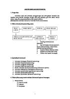
(1-0/1-2//) Fig: Close lap
(0-1/2-1//) Fig: Open lap
01/1-2// Fig: Open laps
0-0/2-2/1-1/3-3// Fig: Misslapping Fig: laying-in Basic lapping movements: I) Pillar/Chain stitch II) Tricot stitch or 1 and 1 lapping movement III) Cord stitch or 2 and 1 lapping movement IV) Longer reciprocating lapping movement V) Atlas stitch or lapping movements VI) Two needle overlap I) Pillar stitch: In the pillar or chain stitch, the same guide always overlaps the same needle.
1-0/0-1 1-0/1-0 Fig: Open lap pillar closed lap pillar stitches stitches This lapping movement will produce chains of loops in unconnected wales, which must be together by the underlaps of a second guide bar. Pillar stitches are made by front guide bars, either to produce vertical stripe effects or to hold the inlays of the guide bars into the structures. Open-lap pillar stitches → Commonly used in warp knitting Closed-lap pillar stitches → Employed on crochet m/c II) Tricot stitch: 1x1 is the simplest of these movements, producing overlaps in alternate wales at alternate course with only one thread crossing between adjacent wales.
Closed open 1-2/1-0// 2-1/0-1// The links in tricot are seen in the back side of fabric One needle space underlap end one needle overlap Called single bar fabric III) Cord stitch: 2x1 is cord lap. Two threads will cross between wales.
Open cord 3-2/0-1//
Closed cord 2-3/1-0//
IV) Longer reciprocating lapping movements: a. Satin stitch or lap: three threads will cross between wales with a 3x1 This satin is produced by increasing under shogging movement in one needle space The length of link is more than cord
Chain notation- 4-3/0-1// 3-4/1-/// Open lap close lap This loops are formed in adjacent courses and in each 3 wales b. Velvet lap:
5-4/0-1// 4-5/1-0// Four threads will cross between wales with a 4x1 This loops are produced between each 4 wales The link length is much more than satin, cord stitches V) Atlas stitch: The structure is formed by the combination of open and close laps. This guide bar laps progressively in the same direction for a minimum of two consecutive courses, normally followed by an identical lapping movement in the opposite direction. a. Tricot atlas: I) Two course tricot atlas II) Three course tricot atlas
Two course
3-4/3-2/2-1/1-0/1-2/2-3// Three course Tricot atlas b. Cord type atlas: This type atlas is form on the basis of cord stitch
4-5/3-2/1-0/2-3// 5 wales and 4 course in repeat
c. Satin type atlas: On the basis of satin stitch principle 7 wales and 4 course in each repeat d. Velvet type atlas: On the basis of velvet stitch principle In each repeat at least 9 wales and 4 course
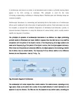
0-7/4-3/1-0/3-4// Satin type atlas VI) Two needle overlaps: In chain stitch, 2 needle space
8-9/5-4/1-0/4-5// velvet type atlas
0-0/2-2/0-0/2-2//