![Engine Control System - 2003 Micra K12 [PDF]](https://pdfs.asia/img/200x200/engine-control-system-2003-micra-k12.jpg)
22 0 7 MB
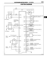
ENGINE CONTROL SYSTEM
B ENGINE A
SECTION
ENGINE CONTROL SYSTEM
EC
C
D
CR (WITH EURO-OBD) INDEX FOR DTC .......................................................11 Alphabetical Index ...................................................11 DTC No. Index ....................................................... 13 PRECAUTIONS ........................................................ 16 Precautions for Supplemental Restraint System (SRS) “AIR BAG” and “SEAT BELT PRE-TENSIONER” ................................................................ 16 Maintenance Information ........................................ 16 On Board Diagnostic (OBD) System of Engine and A/T .......................................................................... 16 Precaution .............................................................. 17 Wiring Diagrams and Trouble Diagnosis ................ 19 PREPARATION ......................................................... 20 Special Service Tools ............................................. 20 Commercial Service Tools ...................................... 20 ENGINE CONTROL SYSTEM .................................. 22 System Diagram ..................................................... 22 Vacuum Hose Drawing ........................................... 23 System Chart ......................................................... 24 Multiport Fuel Injection (MFI) System .................... 24 Electronic Ignition (EI) System ............................... 26 Air Conditioning Cut Control ................................... 27 Fuel Cut Control (at No Load and High Engine Speed) .................................................................... 28 CAN Communication .............................................. 29 BASIC SERVICE PROCEDURE .............................. 41 Idle Speed and Ignition Timing Check .................... 41 Accelerator Pedal Released Position Learning ...... 42 Throttle Valve Closed Position Learning ................ 42 Idle Air Volume Learning ........................................ 42 Fuel Pressure Check .............................................. 44 ON BOARD DIAGNOSTIC (OBD) SYSTEM ............ 47 Introduction ............................................................ 47 Two Trip Detection Logic ........................................ 47 Emission-related Diagnostic Information ................ 48 NATS (Nissan Anti-theft System) ........................... 60 Malfunction Indicator (MI) ....................................... 60 OBD System Operation Chart ................................ 63
TROUBLE DIAGNOSIS ............................................ 69 Trouble Diagnosis Introduction ............................... 69 DTC Inspection Priority Chart ................................. 73 Fail-safe Chart ........................................................ 75 Basic Inspection ..................................................... 77 Symptom Matrix Chart ............................................ 82 Engine Control Component Parts Location ............ 87 Circuit Diagram ....................................................... 92 ECM Harness Connector Terminal Layout ............. 94 ECM Terminals and Reference Value ..................... 94 CONSULT-II Function (ENGINE) .......................... 101 Generic Scan Tool (GST) Function ....................... 112 CONSULT-IIReferenceValueinDataMonitorMode . 113 Major Sensor Reference Graph in Data Monitor Mode ..................................................................... 116 TROUBLE DIAGNOSIS - SPECIFICATION VALUE. 119 Description ............................................................ 119 Testing Condition .................................................. 119 Inspection Procedure ............................................ 119 Diagnostic Procedure ........................................... 120 TROUBLE DIAGNOSIS FOR INTERMITTENT INCIDENT ....................................................................... 124 Description ............................................................ 124 Diagnostic Procedure ........................................... 124 POWER SUPPLY CIRCUIT FOR ECM ................... 125 Wiring Diagram ..................................................... 125 Diagnostic Procedure ........................................... 126 DTC U1000, U1001 CAN COMMUNICATION LINE. 130 Description ............................................................ 130 On Board Diagnosis Logic .................................... 130 DTC Confirmation Procedure ............................... 130 Wiring Diagram ..................................................... 131 Diagnostic Procedure ........................................... 132 DTC P0011 IVT CONTROL ..................................... 133 Description ............................................................ 133 CONSULT-IIReferenceValueinDataMonitorMode . 133 On Board Diagnosis Logic .................................... 134
EC-1
E
F
cardiagn.com
CONTENTS
G
H
I
J
K
L
M
CONSULT-IIReferenceValueinDataMonitorMode .169 On Board Diagnosis Logic .................................... 169 DTC Confirmation Procedure ................................ 170 Wiring Diagram ..................................................... 171 Diagnostic Procedure ............................................ 172 Component Inspection ..........................................173 Removal and Installation ....................................... 174 DTC P0133 HO2S1 ................................................. 175 Component Description ........................................ 175 CONSULT-IIReferenceValueinDataMonitorMode .175 On Board Diagnosis Logic .................................... 175 DTC Confirmation Procedure ................................ 176 Overall Function Check ......................................... 177 Wiring Diagram ..................................................... 178 Diagnostic Procedure ............................................ 179 Component Inspection ..........................................182 Removal and Installation ....................................... 184 DTC P0134 HO2S1 ................................................. 185 Component Description ........................................ 185 CONSULT-IIReferenceValueinDataMonitorMode .185 On Board Diagnosis Logic .................................... 185 DTC Confirmation Procedure ................................ 186 Overall Function Check ......................................... 186 Wiring Diagram ..................................................... 188 Diagnostic Procedure ............................................ 189 Component Inspection ..........................................190 Removal and Installation ....................................... 191 DTC P0138 HO2S2 ................................................. 192 Component Description ........................................ 192 CONSULT-IIReferenceValueinDataMonitorMode .192 On Board Diagnosis Logic .................................... 192 DTC Confirmation Procedure ................................ 192 Wiring Diagram ..................................................... 194 Diagnostic Procedure ............................................ 195 Component Inspection ..........................................196 Removal and Installation ....................................... 198 DTC P0139 HO2S2 ................................................. 199 Component Description ........................................ 199 CONSULT-IIReferenceValueinDataMonitorMode .199 On Board Diagnosis Logic .................................... 199 DTC Confirmation Procedure ................................ 200 Overall Function Check ......................................... 201 Wiring Diagram ..................................................... 202 Diagnostic Procedure ............................................ 203 Component Inspection ..........................................205 Removal and Installation ....................................... 207 DTCP0171FUELINJECTIONSYSTEMFUNCTION.208 On Board Diagnosis Logic .................................... 208 DTC Confirmation Procedure ................................ 208 Wiring Diagram ..................................................... 210 Diagnostic Procedure ............................................ 211 DTCP0172FUELINJECTIONSYSTEMFUNCTION.215 On Board Diagnosis Logic .................................... 215 DTC Confirmation Procedure ................................ 215
EC-2
cardiagn.com
DTC Confirmation Procedure ............................... 134 Diagnostic Procedure ........................................... 135 DTC P0031, P0032 HO2S1 HEATER ..................... 136 Description ............................................................ 136 CONSULT-IIReferenceValueinDataMonitorMode . 136 On Board Diagnosis Logic .................................... 136 DTC Confirmation Procedure ............................... 136 Wiring Diagram ..................................................... 138 Diagnostic Procedure ........................................... 139 Component Inspection .......................................... 141 Removal and Installation ...................................... 141 DTC P0037, P0038 HO2S2 HEATER ..................... 142 Description ............................................................ 142 CONSULT-IIReferenceValueinDataMonitorMode . 142 On Board Diagnosis Logic .................................... 142 DTC Confirmation Procedure ............................... 142 Wiring Diagram ..................................................... 144 Diagnostic Procedure ........................................... 145 Component Inspection .......................................... 147 Removal and Installation ...................................... 147 DTC P0107, P0108 MANIFOLD ABSOLUTE PRESSURE SENSOR ....................................................... 148 Component Description ........................................ 148 On Board Diagnosis Logic .................................... 148 DTC Confirmation Procedure ............................... 148 Wiring Diagram ..................................................... 149 Diagnostic Procedure ........................................... 150 Component Inspection .......................................... 151 Removal and Installation ...................................... 152 DTC P0112, P0113 IAT SENSOR ........................... 153 Component Description ........................................ 153 On Board Diagnosis Logic .................................... 153 DTC Confirmation Procedure ............................... 153 Wiring Diagram ..................................................... 155 Diagnostic Procedure ........................................... 156 Component Inspection .......................................... 157 Removal and Installation ...................................... 157 DTC P0117, P0118 ECT SENSOR .......................... 158 Component Description ........................................ 158 On Board Diagnosis Logic .................................... 158 DTC Confirmation Procedure ............................... 159 Wiring Diagram ..................................................... 160 Diagnostic Procedure ........................................... 161 Component Inspection .......................................... 162 Removal and Installation ...................................... 162 DTC P0122, P0123 TP SENSOR ............................ 163 Component Description ........................................ 163 CONSULT-IIReferenceValueinDataMonitorMode . 163 On Board Diagnosis Logic .................................... 163 DTC Confirmation Procedure ............................... 163 Wiring Diagram ..................................................... 165 Diagnostic Procedure ........................................... 166 Component Inspection .......................................... 168 Remove and Installation ....................................... 168 DTC P0132 HO2S1 ................................................. 169 Component Description ........................................ 169
On Board Diagnosis Logic .................................... 261 DTC Confirmation Procedure ............................... 261 Wiring Diagram ..................................................... 262 Diagnostic Procedure ........................................... 263 Component Inspection .......................................... 265 Removal and Installation ...................................... 266 DTC P0340 CMP SENSOR (PHASE) ..................... 267 Component Description ........................................ 267 On Board Diagnosis Logic .................................... 267 DTC Confirmation Procedure ............................... 267 Wiring Diagram ..................................................... 268 Diagnostic Procedure ........................................... 269 Component Inspection .......................................... 271 Removal and Installation ...................................... 272 DTC P0420 THREE WAY CATALYST FUNCTION. 273 On Board Diagnosis Logic .................................... 273 DTC Confirmation Procedure ............................... 273 Overall Function Check ........................................ 274 Diagnostic Procedure ........................................... 275 DTC P0444 EVAP CANISTER PURGE VOLUME CONTROL SOLENOID VALVE ............................... 278 Description ............................................................ 278 CONSULT-IIReferenceValueinDataMonitorMode . 278 On Board Diagnosis Logic .................................... 278 DTC Confirmation Procedure ............................... 279 Wiring Diagram ..................................................... 280 Diagnostic Procedure ........................................... 281 Component Inspection .......................................... 283 Removal and Installation ...................................... 283 DTC P0500 VSS ...................................................... 284 Description ............................................................ 284 On Board Diagnosis Logic .................................... 284 DTC Confirmation Procedure ............................... 284 Overall Function Check ........................................ 284 Diagnostic Procedure ........................................... 285 DTC P0605 ECM ..................................................... 286 Component Description ........................................ 286 On Board Diagnosis Logic .................................... 286 DTC Confirmation Procedure ............................... 286 Diagnostic Procedure ........................................... 287 DTC P1065 ECM POWER SUPPLY ....................... 289 Component Description ........................................ 289 On Board Diagnosis Logic .................................... 289 DTC Confirmation Procedure ............................... 289 Wiring Diagram ..................................................... 290 Diagnostic Procedure ........................................... 291 DTC P1111 IVT CONTROL SOLENOID VALVE ..... 293 Component Description ........................................ 293 CONSULT-IIReferenceValueinDataMonitorMode . 293 On Board Diagnosis Logic .................................... 293 DTC Confirmation Procedure ............................... 293 Wiring Diagram ..................................................... 294 Diagnostic Procedure ........................................... 295 Component Inspection .......................................... 296 Removal and Installation ...................................... 296 DTC P1121 ELECTRIC THROTTLE CONTROL
EC-3
A
EC
C
D
E
F
cardiagn.com
Wiring Diagram .................................................... 217 Diagnostic Procedure ........................................... 218 DTC P0221 TP SENSOR ........................................ 221 Component Description ........................................ 221 CONSULT-IIReferenceValueinDataMonitorMode . 221 On Board Diagnosis Logic ................................... 221 DTC Confirmation Procedure ............................... 221 Wiring Diagram .................................................... 223 Diagnostic Procedure ........................................... 224 Component Inspection ......................................... 226 Remove and Installation ....................................... 226 DTC P0222, P0223 TP SENSOR ........................... 227 Component Description ........................................ 227 CONSULT-IIReferenceValueinDataMonitorMode . 227 On Board Diagnosis Logic ................................... 227 DTC Confirmation Procedure ............................... 227 Wiring Diagram .................................................... 229 Diagnostic Procedure ........................................... 230 Component Inspection ......................................... 232 Remove and Installation ....................................... 232 DTC P0226 APP SENSOR ..................................... 233 Component Description ........................................ 233 CONSULT-IIReferenceValueinDataMonitorMode . 233 On Board Diagnosis Logic ................................... 233 DTC Confirmation Procedure ............................... 233 Wiring Diagram .................................................... 235 Diagnostic Procedure ........................................... 238 Component Inspection ......................................... 241 Remove and Installation ....................................... 241 DTC P0227, P0228 APP SENSOR ........................ 242 Component Description ........................................ 242 CONSULT-IIReferenceValueinDataMonitorMode . 242 On Board Diagnosis Logic ................................... 242 DTC Confirmation Procedure ............................... 242 Wiring Diagram .................................................... 244 Diagnostic Procedure ........................................... 247 Component Inspection ......................................... 249 Remove and Installation ....................................... 250 DTC P0300 - P0304 MULTIPLE CYLINDER MISFIRE, NO. 1 - 4 CYLINDER MISFIRE ..................... 251 On Board Diagnosis Logic ................................... 251 DTC Confirmation Procedure ............................... 251 Diagnostic Procedure ........................................... 252 DTC P0327, P0328 KS ........................................... 257 Component Description ........................................ 257 On Board Diagnosis Logic ................................... 257 DTC Confirmation Procedure ............................... 257 Wiring Diagram .................................................... 258 Diagnostic Procedure ........................................... 259 Component Inspection ......................................... 260 Removal and Installation ...................................... 260 DTC P0335 CKP SENSOR (POS) .......................... 261 Component Description ........................................ 261 CONSULT-IIReferenceValueinDataMonitorMode . 261
G
H
I
J
K
L
M
Diagnostic Procedure ............................................ 332 Component Inspection ..........................................334 Removal and Installation ....................................... 336 DTC P1147 HO2S2 .................................................. 337 Component Description ........................................ 337 CONSULT-IIReferenceValueinDataMonitorMode .337 On Board Diagnosis Logic .................................... 337 DTC Confirmation Procedure ................................ 338 Overall Function Check ......................................... 339 Wiring Diagram ..................................................... 340 Diagnostic Procedure ............................................ 341 Component Inspection ..........................................343 Removal and Installation ....................................... 345 DTC P1171 INTAKE ERROR .................................. 346 On Board Diagnosis Logic .................................... 346 DTC Confirmation Procedure ................................ 346 Wiring Diagram ..................................................... 347 Diagnostic Procedure ............................................ 348 DTC P1211 TCS CONTROL UNIT .......................... 350 Description ............................................................ 350 On Board Diagnosis Logic .................................... 350 DTC Confirmation Procedure ................................ 350 Diagnostic Procedure ............................................ 350 DTC P1212 TCS COMMUNICATION LINE ............. 351 Description ............................................................ 351 On Board Diagnosis Logic .................................... 351 DTC Confirmation Procedure ................................ 351 Diagnostic Procedure ............................................ 351 DTC P1217 ENGINE OVER TEMPERATURE ........ 352 System Description ............................................... 352 CONSULT-IIReferenceValueinDataMonitorMode .353 On Board Diagnosis Logic .................................... 353 Overall Function Check ......................................... 354 Wiring Diagram ..................................................... 356 Diagnostic Procedure ............................................ 358 Main 12 Causes of Overheating ........................... 365 Component Inspection ..........................................365 DTC P1223, P1224 TP SENSOR ............................ 366 Component Description ........................................ 366 CONSULT-IIReferenceValueinDataMonitorMode .366 On Board Diagnosis Logic .................................... 366 DTC Confirmation Procedure ................................ 366 Wiring Diagram ..................................................... 368 Diagnostic Procedure ............................................ 369 Component Inspection ..........................................371 Remove and Installation ....................................... 371 DTC P1225 TP SENSOR ........................................ 372 Component Description ........................................ 372 On Board Diagnosis Logic .................................... 372 DTC Confirmation Procedure ................................ 372 Diagnostic Procedure ............................................ 373 Remove and Installation ....................................... 373 DTC P1226 TP SENSOR ........................................ 374 Component Description ........................................ 374 On Board Diagnosis Logic .................................... 374 DTC Confirmation Procedure ................................ 374
EC-4
cardiagn.com
ACTUATOR ............................................................. 297 Component Description ........................................ 297 On Board Diagnosis Logic .................................... 297 DTC Confirmation Procedure ............................... 297 Diagnostic Procedure ........................................... 298 DTC P1122 ELECTRIC THROTTLE CONTROL FUNCTION .............................................................. 299 Description ............................................................ 299 On Board Diagnosis Logic .................................... 299 DTC Confirmation Procedure ............................... 299 Wiring Diagram ..................................................... 300 Diagnostic Procedure ........................................... 301 Component Inspection .......................................... 304 Remove and Installation ....................................... 304 DTC P1124, P1126 THROTTLE CONTROL MOTOR RELAY ..................................................................... 305 Component Description ........................................ 305 CONSULT-IIReferenceValueinDataMonitorMode . 305 On Board Diagnosis Logic .................................... 305 DTC Confirmation Procedure ............................... 305 Wiring Diagram ..................................................... 307 Diagnostic Procedure ........................................... 308 DTC P1128 THROTTLE CONTROL MOTOR ......... 310 Component Description ........................................ 310 On Board Diagnosis Logic .................................... 310 DTC Confirmation Procedure ............................... 310 Wiring Diagram ..................................................... 311 Diagnostic Procedure ........................................... 312 Component Inspection .......................................... 313 Remove and Installation ....................................... 314 DTC P1143 HO2S1 ................................................. 315 Component Description ........................................ 315 CONSULT-IIReferenceValueinDataMonitorMode . 315 On Board Diagnosis Logic .................................... 315 DTC Confirmation Procedure ............................... 316 Overall Function Check ........................................ 316 Diagnostic Procedure ........................................... 317 Component Inspection .......................................... 319 Removal and Installation ...................................... 320 DTC P1144 HO2S1 ................................................. 321 Component Description ........................................ 321 CONSULT-IIReferenceValueinDataMonitorMode . 321 On Board Diagnosis Logic .................................... 321 DTC Confirmation Procedure ............................... 322 Overall Function Check ........................................ 322 Diagnostic Procedure ........................................... 323 Component Inspection .......................................... 325 Removal and Installation ...................................... 326 DTC P1146 HO2S2 ................................................. 327 Component Description ........................................ 327 CONSULT-IIReferenceValueinDataMonitorMode . 327 On Board Diagnosis Logic .................................... 327 DTC Confirmation Procedure ............................... 329 Overall Function Check ........................................ 330 Wiring Diagram ..................................................... 331
. 420 On Board Diagnosis Logic .................................... 420 DTC Confirmation Procedure ............................... 420 Wiring Diagram ..................................................... 422 Diagnostic Procedure ........................................... 423 Component Inspection .......................................... 425 Remove and Installation ....................................... 425 DTC P2138 APP SENSOR ..................................... 426 Component Description ........................................ 426 CONSULT-IIReferenceValueinDataMonitorMode . 426 On Board Diagnosis Logic .................................... 426 DTC Confirmation Procedure ............................... 426 Wiring Diagram ..................................................... 428 Diagnostic Procedure ........................................... 431 Component Inspection .......................................... 434 Remove and Installation ....................................... 434 IGNITION SIGNAL .................................................. 435 Component Description ........................................ 435 Wiring Diagram ..................................................... 436 Diagnostic Procedure ........................................... 439 Component Inspection .......................................... 442 Removal and Installation ...................................... 443 INJECTOR CIRCUIT ............................................... 444 Component Description ........................................ 444 CONSULT-IIReferenceValueinDataMonitorMode . 444 Wiring Diagram ..................................................... 445 Diagnostic Procedure ........................................... 446 Component Inspection .......................................... 449 Removal and Installation ...................................... 449 FUEL PUMP CIRCUIT ............................................ 450 Description ............................................................ 450 CONSULT-IIReferenceValueinDataMonitorMode . 450 Wiring Diagram ..................................................... 451 Diagnostic Procedure ........................................... 452 Component Inspection .......................................... 454 Removal and Installation ...................................... 454 REFRIGERANT PRESSURE SENSOR .................. 455 Component Description ........................................ 455 Wiring Diagram ..................................................... 456 Diagnostic Procedure ........................................... 457 Removal and Installation ...................................... 459 ELECTRICAL LOAD SIGNAL ................................ 460 Description ............................................................ 460 CONSULT-IIReferenceValueinDataMonitorMode . 460 Diagnostic Procedure ........................................... 460 MI & DATA LINK CONNECTORS ........................... 462 Wiring Diagram (LHD Models) .............................. 462 Wiring Diagram (RHD Models) ............................. 463 EVAPORATIVE EMISSION SYSTEM ..................... 464 Description ............................................................ 464 Component Inspection .......................................... 467 POSITIVE CRANKCASE VENTILATION ............... 468 Description ............................................................ 468 Component Inspection .......................................... 468
EC-5
A
EC
C
D
E
F
cardiagn.com
Diagnostic Procedure ........................................... 375 Remove and Installation ....................................... 375 DTC P1227, P1228 APP SENSOR ........................ 376 Component Description ........................................ 376 CONSULT-IIReferenceValueinDataMonitorMode . 376 On Board Diagnosis Logic ................................... 376 DTC Confirmation Procedure ............................... 376 Wiring Diagram .................................................... 378 Diagnostic Procedure ........................................... 381 Component Inspection ......................................... 383 Remove and Installation ....................................... 384 DTC P1229 SENSOR POWER SUPPLY ................ 385 On Board Diagnosis Logic ................................... 385 DTC Confirmation Procedure ............................... 385 Wiring Diagram .................................................... 386 Diagnostic Procedure ........................................... 387 DTC P1706 PNP SWITCH ...................................... 389 Component Description ........................................ 389 CONSULT-IIReferenceValueinDataMonitorMode . 389 On Board Diagnosis Logic ................................... 389 DTC Confirmation Procedure ............................... 389 Overall Function Check ........................................ 390 Wiring Diagram .................................................... 391 Diagnostic Procedure ........................................... 392 DTC P1805 BRAKE SWITCH ................................ 395 Description ........................................................... 395 CONSULT-IIReferenceValueinDataMonitorMode . 395 On Board Diagnosis Logic ................................... 395 FAIL-SAFE MODE ............................................... 395 DTC Confirmation Procedure ............................... 395 Wiring Diagram .................................................... 397 Diagnostic Procedure ........................................... 398 Component Inspection ......................................... 401 DTC P2122, P2123 APP SENSOR ........................ 402 Component Description ........................................ 402 CONSULT-IIReferenceValueinDataMonitorMode . 402 On Board Diagnosis Logic ................................... 402 DTC Confirmation Procedure ............................... 402 Wiring Diagram .................................................... 404 Diagnostic Procedure ........................................... 407 Component Inspection ......................................... 409 Remove and Installation ....................................... 410 DTC P2127, P2128 APP SENSOR .........................411 Component Description .........................................411 CONSULT-IIReferenceValueinDataMonitorMode ..411 On Board Diagnosis Logic ....................................411 DTC Confirmation Procedure ................................411 Wiring Diagram .................................................... 413 Diagnostic Procedure ........................................... 416 Component Inspection ......................................... 418 Remove and Installation ....................................... 419 DTC P2135 TP SENSOR ........................................ 420 Component Description ........................................ 420 CONSULT-IIReferenceValueinDataMonitorMode
G
H
I
J
K
L
M
CR (WITHOUT EURO-OBD) INDEX FOR DTC ..................................................... 472 Alphabetical Index ................................................ 472 DTC No. Index ...................................................... 474 PRECAUTIONS ....................................................... 476 Precautions for Supplemental Restraint System (SRS) “AIR BAG” and “SEAT BELT PRE-TENSIONER” ............................................................... 476 Maintenance Information ...................................... 476 On Board Diagnostic (OBD) System of Engine and A/T ........................................................................ 476 Precaution ............................................................ 477 Wiring Diagrams and Trouble Diagnosis .............. 479 PREPARATION ....................................................... 480 Special Service Tools ........................................... 480 Commercial Service Tools .................................... 480 ENGINE CONTROL SYSTEM ................................ 482 System Diagram ................................................... 482 Vacuum Hose Drawing ......................................... 483 System Chart ........................................................ 484 Multiport Fuel Injection (MFI) System ................... 484 Electronic Ignition (EI) System ............................. 486 Air Conditioning Cut Control ................................. 487 Fuel Cut Control (at No Load and High Engine Speed) .................................................................. 488 CAN Communication ............................................ 489 BASIC SERVICE PROCEDURE ............................. 502 Idle Speed and Ignition Timing Check .................. 502 Accelerator Pedal Released Position Learning .... 503 Throttle Valve Closed Position Learning ............... 503 Idle Air Volume Learning ...................................... 503 Fuel Pressure Check ............................................ 505 ON BOARD DIAGNOSTIC (OBD) SYSTEM .......... 508 Introduction ........................................................... 508 Two Trip Detection Logic ...................................... 508 Emission-related Diagnostic Information .............. 508 NATS (Nissan Anti-theft System) .......................... 511 Malfunction Indicator (MI) ..................................... 511 TROUBLE DIAGNOSIS .......................................... 515 Trouble Diagnosis Introduction ............................. 515 DTC Inspection Priority Chart ............................... 519 Fail-safe Chart ...................................................... 520 Basic Inspection ................................................... 522
Symptom Matrix Chart .......................................... 527 Engine Control Component Parts Location ........... 532 Circuit Diagram ..................................................... 537 ECM Harness Connector Terminal Layout ............ 539 ECM Terminals and Reference Value ................... 539 CONSULT-II Function (ENGINE) .......................... 546 CONSULT-IIReferenceValueinDataMonitorMode .555 Major Sensor Reference Graph in Data Monitor Mode ..................................................................... 558 TROUBLE DIAGNOSIS - SPECIFICATION VALUE.561 Description ............................................................ 561 Testing Condition .................................................. 561 Inspection Procedure ............................................ 561 Diagnostic Procedure ............................................ 562 TROUBLE DIAGNOSIS FOR INTERMITTENT INCIDENT ....................................................................... 566 Description ............................................................ 566 Diagnostic Procedure ............................................ 566 POWER SUPPLY CIRCUIT FOR ECM ................... 567 Wiring Diagram ..................................................... 567 Diagnostic Procedure ............................................ 568 DTC U1000, U1001 CAN COMMUNICATION LINE.572 Description ............................................................ 572 On Board Diagnosis Logic .................................... 572 DTC Confirmation Procedure ................................ 572 Wiring Diagram ..................................................... 573 Diagnostic Procedure ............................................ 574 DTC P0107, P0108 MANIFOLD ABSOLUTE PRESSURE SENSOR ....................................................... 575 Component Description ........................................ 575 On Board Diagnosis Logic .................................... 575 DTC Confirmation Procedure ................................ 575 Wiring Diagram ..................................................... 576 Diagnostic Procedure ............................................ 577 Component Inspection ..........................................578 Removal and Installation ....................................... 579 DTC P0117, P0118 ECT SENSOR .......................... 580 Component Description ........................................ 580 On Board Diagnosis Logic .................................... 580 DTC Confirmation Procedure ................................ 581 Wiring Diagram ..................................................... 582 Diagnostic Procedure ............................................ 583 Component Inspection ..........................................584 Removal and Installation ....................................... 584 DTC P0122, P0123 TP SENSOR ............................ 585 Component Description ........................................ 585 CONSULT-IIReferenceValueinDataMonitorMode .585 On Board Diagnosis Logic .................................... 585 DTC Confirmation Procedure ................................ 585 Wiring Diagram ..................................................... 587 Diagnostic Procedure ............................................ 588 Component Inspection ..........................................590 Remove and Installation ....................................... 590 DTC P0132 HO2S1 ................................................. 591 Component Description ........................................ 591 CONSULT-IIReferenceValueinDataMonitorMode .591
EC-6
cardiagn.com
SERVICE DATA AND SPECIFICATIONS (SDS) .... 470 Fuel Pressure ....................................................... 470 Idle Speed and Ignition Timing ............................. 470 Calculated Load Value .......................................... 470 Manifold absolute pressure sensor ....................... 470 Intake Air Temperature Sensor ............................. 470 Engine Coolant Temperature Sensor ................... 470 Heated Oxygen Sensor 1 Heater ......................... 470 Heated Oxygen sensor 2 Heater .......................... 470 Crankshaft Position Sensor (POS) ....................... 470 Camshaft Position Sensor (PHASE) .................... 470 Throttle Control Motor ........................................... 470 Injector .................................................................. 471 Fuel Pump ............................................................ 471
. 630 On Board Diagnosis Logic .................................... 630 DTC Confirmation Procedure ............................... 630 Wiring Diagram ..................................................... 632 Diagnostic Procedure ........................................... 635 Component Inspection .......................................... 637 Remove and Installation ....................................... 638 DTC P0327, P0328 KS ........................................... 639 Component Description ........................................ 639 On Board Diagnosis Logic .................................... 639 DTC Confirmation Procedure ............................... 639 Wiring Diagram ..................................................... 640 Diagnostic Procedure ........................................... 641 Component Inspection .......................................... 642 Removal and Installation ...................................... 642 DTC P0335 CKP SENSOR (POS) .......................... 643 Component Description ........................................ 643 CONSULT-IIReferenceValueinDataMonitorMode . 643 On Board Diagnosis Logic .................................... 643 DTC Confirmation Procedure ............................... 643 Wiring Diagram ..................................................... 645 Diagnostic Procedure ........................................... 646 Component Inspection .......................................... 648 Removal and Installation ...................................... 649 DTC P0340 CMP SENSOR (PHASE) ..................... 650 Component Description ........................................ 650 On Board Diagnosis Logic .................................... 650 DTC Confirmation Procedure ............................... 650 Wiring Diagram ..................................................... 652 Diagnostic Procedure ........................................... 653 Component Inspection .......................................... 655 Removal and Installation ...................................... 656 DTC P0605 ECM ..................................................... 657 Component Description ........................................ 657 On Board Diagnosis Logic .................................... 657 DTC Confirmation Procedure ............................... 657 Diagnostic Procedure ........................................... 659 DTC P1065 ECM POWER SUPPLY ....................... 660 Component Description ........................................ 660 On Board Diagnosis Logic .................................... 660 DTC Confirmation Procedure ............................... 660 Wiring Diagram ..................................................... 661 Diagnostic Procedure ........................................... 662 DTC P1121 ELECTRIC THROTTLE CONTROL ACTUATOR ............................................................. 664 Component Description ........................................ 664 On Board Diagnosis Logic .................................... 664 DTC Confirmation Procedure ............................... 664 Diagnostic Procedure ........................................... 665 DTC P1122 ELECTRIC THROTTLE CONTROL FUNCTION .............................................................. 667 Description ............................................................ 667 On Board Diagnosis Logic .................................... 667 DTC Confirmation Procedure ............................... 667 Wiring Diagram ..................................................... 668 Diagnostic Procedure ........................................... 669 Component Inspection .......................................... 672 Remove and Installation ....................................... 672
EC-7
A
EC
C
D
E
F
cardiagn.com
On Board Diagnosis Logic ................................... 591 DTC Confirmation Procedure ............................... 592 Wiring Diagram .................................................... 593 Diagnostic Procedure ........................................... 594 Component Inspection ......................................... 595 Removal and Installation ...................................... 596 DTC P0134 HO2S1 ................................................. 597 Component Description ........................................ 597 CONSULT-IIReferenceValueinDataMonitorMode . 597 On Board Diagnosis Logic ................................... 597 Overall Function Check ........................................ 598 Wiring Diagram .................................................... 599 Diagnostic Procedure ........................................... 600 Component Inspection ......................................... 601 Removal and Installation ...................................... 602 DTC P0138 HO2S2 ................................................. 603 Component Description ........................................ 603 CONSULT-IIReferenceValueinDataMonitorMode . 603 On Board Diagnosis Logic ................................... 603 DTC Confirmation Procedure ............................... 603 Wiring Diagram .................................................... 605 Diagnostic Procedure ........................................... 606 Component Inspection ......................................... 607 Removal and Installation ...................................... 608 DTC P0221 TP SENSOR ........................................ 609 Component Description ........................................ 609 CONSULT-IIReferenceValueinDataMonitorMode . 609 On Board Diagnosis Logic ................................... 609 DTC Confirmation Procedure ............................... 609 Wiring Diagram .....................................................611 Diagnostic Procedure ........................................... 612 Component Inspection ......................................... 614 Remove and Installation ....................................... 614 DTC P0222, P0223 TP SENSOR ........................... 615 Component Description ........................................ 615 CONSULT-IIReferenceValueinDataMonitorMode . 615 On Board Diagnosis Logic ................................... 615 DTC Confirmation Procedure ............................... 615 Wiring Diagram .................................................... 617 Diagnostic Procedure ........................................... 618 Component Inspection ......................................... 620 Remove and Installation ....................................... 620 DTC P0226 APP SENSOR ..................................... 621 Component Description ........................................ 621 CONSULT-IIReferenceValueinDataMonitorMode . 621 On Board Diagnosis Logic ................................... 621 DTC Confirmation Procedure ............................... 621 Wiring Diagram .................................................... 623 Diagnostic Procedure ........................................... 626 Component Inspection ......................................... 629 Remove and Installation ....................................... 629 DTC P0227, P0228 APP SENSOR ........................ 630 Component Description ........................................ 630 CONSULT-IIReferenceValueinDataMonitorMode
G
H
I
J
K
L
M
DTC P1226 TP SENSOR ........................................ 711 Component Description ........................................ 711 On Board Diagnosis Logic .................................... 711 DTC Confirmation Procedure ................................ 711 Diagnostic Procedure ............................................ 712 Remove and Installation ....................................... 712 DTC P1227, P1228 APP SENSOR ......................... 713 Component Description ........................................ 713 CONSULT-IIReferenceValueinDataMonitorMode .713 On Board Diagnosis Logic .................................... 713 DTC Confirmation Procedure ................................ 713 Wiring Diagram ..................................................... 715 Diagnostic Procedure ............................................ 718 Component Inspection ..........................................720 Remove and Installation ....................................... 721 DTC P1229 SENSOR POWER SUPPLY ................ 722 On Board Diagnosis Logic .................................... 722 DTC Confirmation Procedure ................................ 722 Wiring Diagram ..................................................... 723 Diagnostic Procedure ............................................ 724 DTC P1805 BRAKE SWITCH ................................. 726 Description ............................................................ 726 CONSULT-IIReferenceValueinDataMonitorMode .726 On Board Diagnosis Logic .................................... 726 FAIL-SAFE MODE ................................................ 726 DTC Confirmation Procedure ................................ 726 Wiring Diagram ..................................................... 728 Diagnostic Procedure ............................................ 729 Component Inspection ..........................................732 DTC P2122, P2123 APP SENSOR ......................... 733 Component Description ........................................ 733 CONSULT-IIReferenceValueinDataMonitorMode .733 On Board Diagnosis Logic .................................... 733 DTC Confirmation Procedure ................................ 733 Wiring Diagram ..................................................... 735 Diagnostic Procedure ............................................ 738 Component Inspection ..........................................740 Remove and Installation ....................................... 741 DTC P2127, P2128 APP SENSOR ......................... 742 Component Description ........................................ 742 CONSULT-IIReferenceValueinDataMonitorMode .742 On Board Diagnosis Logic .................................... 742 DTC Confirmation Procedure ................................ 742 Wiring Diagram ..................................................... 744 Diagnostic Procedure ............................................ 747 Component Inspection ..........................................749 Remove and Installation ....................................... 750 DTC P2135 TP SENSOR ........................................ 751 Component Description ........................................ 751 CONSULT-IIReferenceValueinDataMonitorMode .751 On Board Diagnosis Logic .................................... 751 DTC Confirmation Procedure ................................ 751 Wiring Diagram ..................................................... 753 Diagnostic Procedure ...........................................
EC-8
cardiagn.com
DTC P1124, P1126 THROTTLE CONTROL MOTOR RELAY ..................................................................... 673 Component Description ........................................ 673 CONSULT-IIReferenceValueinDataMonitorMode . 673 On Board Diagnosis Logic .................................... 673 DTC Confirmation Procedure ............................... 673 Wiring Diagram ..................................................... 675 Diagnostic Procedure ........................................... 676 DTC P1128 THROTTLE CONTROL MOTOR ......... 678 Component Description ........................................ 678 On Board Diagnosis Logic .................................... 678 DTC Confirmation Procedure ............................... 678 Wiring Diagram ..................................................... 679 Diagnostic Procedure ........................................... 680 Component Inspection .......................................... 681 Remove and Installation ....................................... 682 DTC P1171 INTAKE ERROR .................................. 683 On Board Diagnosis Logic .................................... 683 DTC Confirmation Procedure ............................... 683 Wiring Diagram ..................................................... 684 Diagnostic Procedure ........................................... 685 DTC P1211 TCS CONTROL UNIT .......................... 687 Description ............................................................ 687 On Board Diagnosis Logic .................................... 687 DTC Confirmation Procedure ............................... 687 Diagnostic Procedure ........................................... 687 DTC P1212 TCS COMMUNICATION LINE ............ 688 Description ............................................................ 688 On Board Diagnosis Logic .................................... 688 DTC Confirmation Procedure ............................... 688 Diagnostic Procedure ........................................... 688 DTC P1217 ENGINE OVER TEMPERATURE ........ 689 System Description ............................................... 689 CONSULT-IIReferenceValueinDataMonitorMode . 690 On Board Diagnosis Logic .................................... 690 Overall Function Check ........................................ 691 Wiring Diagram ..................................................... 693 Diagnostic Procedure ........................................... 695 Main 12 Causes of Overheating ........................... 702 Component Inspection .......................................... 702 DTC P1223, P1224 TP SENSOR ............................ 703 Component Description ........................................ 703 CONSULT-IIReferenceValueinDataMonitorMode . 703 On Board Diagnosis Logic .................................... 703 DTC Confirmation Procedure ............................... 703 Wiring Diagram ..................................................... 705 Diagnostic Procedure ........................................... 706 Component Inspection .......................................... 708 Remove and Installation ....................................... 708 DTC P1225 TP SENSOR ........................................ 709 Component Description ........................................ 709 On Board Diagnosis Logic .................................... 709 DTC Confirmation Procedure ............................... 709 Diagnostic Procedure ........................................... 710 Remove and Installation ....................................... 710
CONSULT-IIReferenceValueinDataMonitorMode . 801 Wiring Diagram ..................................................... 802 Diagnostic Procedure ........................................... 804 Component Inspection .......................................... 806 Removal and Installation ...................................... 807 VSS ......................................................................... 808 Description ............................................................ 808 Diagnostic Procedure ........................................... 808 IVT CONTROL SOLENOID VALVE ........................ 809 Description ............................................................ 809 CONSULT-IIReferenceValueinDataMonitorMode . 810 Wiring Diagram ..................................................... 811 Diagnostic Procedure ........................................... 812 Component Inspection .......................................... 814 Removal and Installation ...................................... 814 PNP SWITCH .......................................................... 815 Component Description ........................................ 815 CONSULT-IIReferenceValueinDataMonitorMode . 815 Wiring Diagram ..................................................... 816 Diagnostic Procedure ........................................... 817 INJECTOR CIRCUIT ............................................... 820 Component Description ........................................ 820 CONSULT-IIReferenceValueinDataMonitorMode . 820 Wiring Diagram ..................................................... 821 Diagnostic Procedure ........................................... 822 Component Inspection .......................................... 825 Removal and Installation ...................................... 825 FUEL PUMP CIRCUIT ............................................ 826 Description ............................................................ 826 CONSULT-IIReferenceValueinDataMonitorMode . 826 Wiring Diagram ..................................................... 827 Diagnostic Procedure ........................................... 828 Component Inspection .......................................... 830 Removal and Installation ...................................... 830 REFRIGERANT PRESSURE SENSOR .................. 831 Component Description ........................................ 831 Wiring Diagram ..................................................... 832 Diagnostic Procedure ........................................... 833 Removal and Installation ...................................... 835 ELECTRICAL LOAD SIGNAL ................................ 836 Description ............................................................ 836 CONSULT-IIReferenceValueinDataMonitorMode . 836 Diagnostic Procedure ........................................... 836 MI & DATA LINK CONNECTORS ........................... 838 Wiring Diagram (LHD Models) .............................. 838 Wiring Diagram (RHD Models) ............................. 839 EVAPORATIVE EMISSION SYSTEM ..................... 840 Description ............................................................ 840 Component Inspection .......................................... 843 POSITIVE CRANKCASE VENTILATION ............... 844 Description ............................................................ 844 Component Inspection .......................................... 844
EC-9
A
EC
C
D
E
F
cardiagn.com
Component Inspection ......................................... 756 Remove and Installation ....................................... 756 DTC P2138 APP SENSOR ..................................... 757 Component Description ........................................ 757 CONSULT-IIReferenceValueinDataMonitorMode . 757 On Board Diagnosis Logic ................................... 757 DTC Confirmation Procedure ............................... 757 Wiring Diagram .................................................... 759 Diagnostic Procedure ........................................... 762 Component Inspection ......................................... 765 Remove and Installation ....................................... 765 HO2S1 HEATER ..................................................... 766 Description ........................................................... 766 CONSULT-IIReferenceValueinDataMonitorMode . 766 Wiring Diagram .................................................... 767 Diagnostic Procedure ........................................... 768 Component Inspection ......................................... 770 Removal and Installation ...................................... 770 HO2S2 HEATER ..................................................... 771 Description ........................................................... 771 CONSULT-IIReferenceValueinDataMonitorMode . 771 Wiring Diagram .................................................... 772 Diagnostic Procedure ........................................... 773 Component Inspection ......................................... 775 Removal and Installation ...................................... 775 IAT SENSOR ........................................................... 776 Component Description ........................................ 776 Wiring Diagram .................................................... 777 Diagnostic Procedure ........................................... 778 Component Inspection ......................................... 779 Removal and Installation ...................................... 779 HO2S1 .................................................................... 780 Component Description ........................................ 780 CONSULT-IIReferenceValueinDataMonitorMode . 780 Wiring Diagram .................................................... 781 Diagnostic Procedure ........................................... 782 Component Inspection ......................................... 784 Removal and Installation ...................................... 785 HO2S2 .................................................................... 786 Component Description ........................................ 786 CONSULT-IIReferenceValueinDataMonitorMode . 786 Wiring Diagram .................................................... 787 Diagnostic Procedure ........................................... 788 Component Inspection ......................................... 790 Removal and Installation ...................................... 791 IGNITION SIGNAL .................................................. 792 Component Description ........................................ 792 Wiring Diagram .................................................... 793 Diagnostic Procedure ........................................... 796 Component Inspection ......................................... 799 Removal and Installation ...................................... 800 EVAP CANISTER PURGE VOLUME CONTROL SOLENOID VALVE ................................................. 801 Description ........................................................... 801
G
H
I
J
K
L
M
Heated Oxygen Sensor 1 Heater .......................... 846 Heated Oxygen sensor 2 Heater .......................... 846 Crankshaft Position Sensor (POS) ....................... 846 Camshaft Position Sensor (PHASE) ..................... 846 Throttle Control Motor ........................................... 846 Injector .................................................................. 847 Fuel Pump ............................................................. 847
cardiagn.com
SERVICE DATA AND SPECIFICATIONS (SDS) .... 846 Fuel Pressure ....................................................... 846 Idle Speed and Ignition Timing ............................. 846 Calculated Load Value .......................................... 846 Manifold absolute pressure sensor ....................... 846 Intake Air Temperature Sensor ............................. 846 Engine Coolant Temperature Sensor ................... 846
EC-10
INDEX FOR DTC [CR (WITH EURO-OBD)]
INDEX FOR DTC Alphabetical Index [CR (WITH EURO-OBD)]
PFP:00024
A EBS00O2P
Check if the vehicle is a model with Euro-OBD (E-OBD) system or not by the “Type approval number” on the identification plate. Refer to GI-44, "IDENTIFICATION INFORMATION" . EC NOTE: If DTC U1000 or U1001 is displayed with other DTC, first perform the trouble diagnosis for DTC U1000, U1001. Refer to EC-130, "DTC U1000, U1001 CAN COMMUNICATION LINE" . C Items (CONSULT-II screen terms)
DTC*1 CONSULT-II
MI lighting up
Reference page
D
ABSL PRES SEN/CIRC
P0107
0107
2
×
EC-148
ABSL PRES SEN/CIRC
P0108
0108
2
×
EC-148
APP SEN 1/CIRC
P0227
0227
1
×
EC-242
APP SEN 1/CIRC
P0228
0228
1
×
EC-242
APP SEN 1/CIRC
P2122
2122
1
×
EC-402
APP SEN 1/CIRC
P2123
2123
1
×
EC-402
APP SEN 2/CIRC
P1227
1227
1
×
EC-376
APP SEN 2/CIRC
P1228
1228
1
×
EC-376
APP SEN 2/CIRC
P2127
2127
1
×
EC-411
APP SEN 2/CIRC
P2128
2128
1
×
EC-411
APP SENSOR
P0226
0226
1
×
EC-233
APP SENSOR
P2138
2138
1
×
EC-426
ATF TEMP SEN/CIRC
P0710
0710
2
×
AT-120
A/T 1ST GR FNCTN
P0731
0731
2
×
AT-135
A/T 2ND GR FNCTN
P0732
0732
2
×
AT-141
A/T 3RD GR FNCTN
P0733
0733
2
×
AT-147
A/T 4TH GR FNCTN
P0734
0734
2
×
AT-153
BRAKE SW/CIRCUIT
P1805
1805
2
—
EC-395
CAN COMM CIRCUIT
U1000
1000*5
1
×
EC-130
cardiagn.com
GST*2
Trip ECM*3
CAN COMM CIRCUIT
U1001
1001*5
2
—
EC-130
L
CKP SEN/CIRCUIT
P0335
0335
2
×
EC-261
CMP SEN/CIRC-B1
P0340
0340
2
×
EC-267
CTP LEARNING
P1225
1225
2
—
EC-372
CTP LEARNING
P1226
1226
2
—
EC-374
CYL 1 MISFIRE
P0301
0301
2
×
EC-251
CYL 2 MISFIRE
P0302
0302
2
×
EC-251
CYL 3 MISFIRE
P0303
0303
2
×
EC-251
CYL 4 MISFIRE
P0304
0304
2
×
EC-251
ECM
P0605
0605
1 or 2
× or —
EC-286
ECM BACK UP/CIRC
P1065
1065
2
×
EC-289
ECT SEN/CIRCUIT
P0117
0117
1
×
EC-158
ECT SEN/CIRCUIT
P0118
0118
1
×
EC-158
ENGINE SPEED SIG
P0725
0725
2
×
AT-131
ENG OVER TEMP
P1217
1217
1
×
EC-352
ETC ACTR
P1121
1121
1
×
EC-297
EC-11
E
F
G
H
I
J
K
M
INDEX FOR DTC [CR (WITH EURO-OBD)] CONSULT-II
Trip
MI lighting up
Reference page
3
GST*2
ECM*
ETC FUNCTION/CIRC
P1122
1122
1
×
EC-299
ETC MOT
P1128
1128
1
×
EC-310
ETC MOT PWR
P1124
1124
1
×
EC-305
ETC MOT PWR
P1126
1126
1
×
EC-305
FUEL SYS-LEAN-B1
P0171
0171
2
×
EC-208
FUEL SYS-RICH-B1
P0172
0172
2
×
EC-215
HO2S1 (B1)
P0132
0132
2
×
EC-169
HO2S1 (B1)
P0133
0133
2
×
EC-175
HO2S1 (B1)
P0134
0134
2
×
EC-185
HO2S1 (B1)
P1143
1143
2
×
EC-315
HO2S1 (B1)
P1144
1144
2
×
EC-321
HO2S1 HTR (B1)
P0031
0031
2
×
EC-136
HO2S1 HTR (B1)
P0032
0032
2
×
EC-136
HO2S2 (B1)
P0138
0138
2
×
EC-192
HO2S2 (B1)
P0139
0139
2
×
EC-199
HO2S2 (B1)
P1146
1146
2
×
EC-327
HO2S2 (B1)
P1147
1147
2
×
EC-337
HO2S2 HTR (B1)
P0037
0037
2
×
EC-142
HO2S2 HTR (B1)
P0038
0038
2
×
EC-142
IAT SEN/CIRCUIT
P0112
0112
2
×
EC-153
IAT SEN/CIRCUIT
P0113
0113
2
×
EC-153
INTAKE ERROR
P1171
1171
1
×
EC-346
INT/V TIM CONT-B1
P0011
0011
2
—
EC-133
INT/V TIM V/CIR-B1
P1111
1111
2
×
EC-293
KNOCK SEN/CIRC-B1
P0327
0327
2
—
EC-257
KNOCK SEN/CIRC-B1
P0328
0328
2
—
EC-257
L/PRESS SOL/CIRC
P0745
0745
2
×
AT-166
MULTI CYL MISFIRE
P0300
0300
2
×
EC-251
NATS MALFUNCTION
P1610 - P1615
1610 - 1615
2
—
EC-60
NO DTC IS DETECTED. FURTHER TESTING MAY BE REQUIRED.
No DTC
Flashing*4
—
Flashing*4
EC-61
NO DTC IS DETECTED. FURTHER TESTING MAY BE REQUIRED.
P0000
0000
—
—
—
O/R CLTCH SOL/CIRC
P1760
1760
2
×
AT-188
PNP SW/CIRC
P0705
0705
2
×
AT-114
P-N POS SW/CIRCUIT
P1706
1706
2
×
EC-389
PURG VOLUME CONT/V
P0444
0444
2
×
EC-278
SFT SOL A/CIRC
P0750
0750
1
×
AT-173
SFT SOL B/CIRC
P0755
0755
1
×
AT-178
SENSOR POWER/CIRC
P1229
1229
1
×
EC-385
TCC SOLENOID/CIRC
P0740
0740
2
×
AT-161
TCS C/U FUNCTN
P1211
1211
2
—
EC-350
EC-12
cardiagn.com
DTC*1 Items (CONSULT-II screen terms)
INDEX FOR DTC [CR (WITH EURO-OBD)] CONSULT-II
Trip
MI lighting up
Reference page
3
GST*2
ECM*
TCS/CIRC
P1212
1212
2
—
EC-351
TP SEN/CIRC A/T
P1705
1705
1
×
AT-183
TP SEN 1/CIRC
P0222
0222
1
×
EC-227
TP SEN 1/CIRC
P0223
0223
1
×
EC-227
TP SEN 2/CIRC
P0122
0122
1
×
EC-163
TP SEN 2/CIRC
P0123
0123
1
×
EC-163
TP SEN 2/CIRC
P1223
1223
1
×
EC-366
TP SEN 2/CIRC
P1224
1224
1
×
EC-366
TP SENSOR
P0221
0221
1
×
EC-221
TP SENSOR
P2135
2135
1
×
EC-420
TW CATALYST SYS-B1
P0420
0420
2
×
EC-273
VEH SPD SEN/CIRC
P0720
0720
2
×
AT-126
VEH SPEED SEN/CIRC
P0500
0500
2
×
EC-284
*1: 1st trip DTC No. is the same as DTC No. *2: This number is prescribed by ISO 15031-5. *3: In Diagnostic Test Mode II (Self-diagnostic results), this number is controlled by NISSAN. *4: When engine is running. *5: The troubleshooting for this DTC needs CONSULT-II.
C
D
E
F
H
EBS00O2Q
NOTE: If DTC U1000 or U1001 is displayed with other DTC, first perform the trouble diagnosis for DTC U1000, U1001. Refer to EC-130, "DTC U1000, U1001 CAN COMMUNICATION LINE" .
I
J
DTC*1 GST*2
EC
G
DTC No. Index
CONSULT-II
A
cardiagn.com
DTC*1 Items (CONSULT-II screen terms)
ECM*3
Items (CONSULT-II screen terms)
Trip
MI lighting up
Reference page
K
NO DTC IS DETECTED. FURTHER TESTING MAY BE REQUIRED.
—
Flashing*4
EC-61
No DTC
Flashing*4
U1000
1000*5
CAN COMM CIRCUIT
1
×
EC-130
U1001
1001*5
CAN COMM CIRCUIT
2
—
EC-130
P0000
0000
NO DTC IS DETECTED. FURTHER TESTING MAY BE REQUIRED.
—
—
—
P0011
0011
INT/V TIM CONT-B1
2
—
EC-133
P0031
0031
HO2S1 HTR (B1)
2
×
EC-136
P0032
0032
HO2S1 HTR (B1)
2
×
EC-136
P0037
0037
HO2S2 HTR (B1)
2
×
EC-142
P0038
0038
HO2S2 HTR (B1)
2
×
EC-142
P0107
0107
ABSL PRES SEN/CIRC
2
×
EC-148
P0108
0108
ABSL PRES SEN/CIRC
2
×
EC-148
P0112
0112
IAT SEN/CIRCUIT
2
×
EC-153
P0113
0113
IAT SEN/CIRCUIT
2
×
EC-153
P0117
0117
ECT SEN/CIRCUIT
1
×
EC-158
P0118
0118
ECT SEN/CIRCUIT
1
×
EC-158
P0122
0122
TP SEN 2/CIRC
1
×
EC-163
EC-13
L
M
INDEX FOR DTC [CR (WITH EURO-OBD)] CONSULT-II
Items (CONSULT-II screen terms)
3
Trip
MI lighting up
Reference page
GST*2
ECM*
P0123
0123
TP SEN 2/CIRC
1
×
EC-163
P0132
0132
HO2S1 (B1)
2
×
EC-169
P0133
0133
HO2S1 (B1)
2
×
EC-175
P0134
0134
HO2S1 (B1)
2
×
EC-185
P0138
0138
HO2S2 (B1)
2
×
EC-192
P0139
0139
HO2S2 (B1)
2
×
EC-199
P0171
0171
FUEL SYS-LEAN-B1
2
×
EC-208
P0172
0172
FUEL SYS-RICH-B1
2
×
EC-215
P0221
0221
TP SENSOR
1
×
EC-221
P0222
0222
TP SEN 1/CIRC
1
×
EC-227
P0223
0223
TP SEN 1/CIRC
1
×
EC-227
P0226
0226
6
APP SENSOR*
1
×
EC-233
P0227
0227
APP SEN 1/CIRC*6
1
×
EC-242
P0228
0228
APP SEN 1/CIRC*6
1
×
EC-242
P0300
0300
MULTI CYL MISFIRE
2
×
EC-251
P0301
0301
CYL 1 MISFIRE
2
×
EC-251
P0302
0302
CYL 2 MISFIRE
2
×
EC-251
P0303
0303
CYL 3 MISFIRE
2
×
EC-251
P0304
0304
CYL 4 MISFIRE
2
×
EC-251
P0327
0327
KNOCK SEN/CIRC-B1
2
—
EC-257
P0328
0328
KNOCK SEN/CIRC-B1
2
—
EC-257
P0335
0335
CKP SEN/CIRCUIT
2
×
EC-261
P0340
0340
CMP SEN/CIRC-B1
2
×
EC-267
P0420
0420
TW CATALYST SYS-B1
2
×
EC-273
P0444
0444
PURG VOLUME CONT/V
2
×
EC-278
P0500
0500
VEH SPEED SEN/CIRC
2
×
EC-284
P0605
0605
ECM
1 or 2
× or —
EC-286
P0705
0705
PNP SW/CIRC
2
×
AT-114
P0710
0710
ATF TEMP SEN/CIRC
2
×
AT-120
P0720
0720
VEH SPD SEN/CIRC
2
×
AT-126
P0725
0725
ENGINE SPEED SIG
2
×
AT-131
P0731
0731
A/T 1ST GR FNCTN
2
×
AT-135
P0732
0732
A/T 2ND GR FNCTN
2
×
AT-141
P0733
0733
A/T 3RD GR FNCTN
2
×
AT-147
P0734
0734
A/T 4TH GR FNCTN
2
×
AT-153
P0740
0740
TCC SOLENOID/CIRC
2
×
AT-161
P0745
0745
L/PRESS SOL/CIRC
2
×
AT-166
P0750
0750
SFT SOL A/CIRC
1
×
AT-173
P0755
0755
SFT SOL B/CIRC
1
×
AT-178
P1065
1065
ECM BACK UP/CIRC
2
×
EC-289
P1111
1111
INT/V TIM V/CIR-B1
2
×
EC-293
P1121
1121
ETC ACTR
1
×
EC-297
EC-14
cardiagn.com
DTC*1
INDEX FOR DTC [CR (WITH EURO-OBD)] CONSULT-II
3
Items (CONSULT-II screen terms)
Trip
MI lighting up
Reference page
GST*2
ECM*
P1122
1122
ETC FUNCTION/CIRC
1
×
EC-299
P1124
1124
ETC MOT PWR
1
×
EC-305
P1126
1126
ETC MOT PWR
1
×
EC-305
P1128
1128
ETC MOT
1
×
EC-310
P1143
1143
HO2S1 (B1)
2
×
EC-315
P1144
1144
HO2S1 (B1)
2
×
EC-321
P1146
1146
HO2S2 (B1)
2
×
EC-327
P1147
1147
HO2S2 (B1)
2
×
EC-337
P1171
1171
INTAKE ERROR
1
×
EC-346
P1211
1211
TCS C/U FUNCTN
2
—
EC-350
P1212
1212
TCS/CIRC
2
—
EC-351
P1217
1217
ENG OVER TEMP
1
×
EC-352
P1223
1223
TP SEN 2/CIRC*6
1
×
EC-366
P1224
1224
6
TP SEN 2/CIRC*
1
×
EC-366
P1225
1225
CTP LEARNING
2
—
EC-372
P1226
1226
CTP LEARNING
2
—
EC-374
P1227
1227
APP SEN 2/CIRC*6
1
×
EC-376
P1228
1228
APP SEN 2/CIRC*6
1
×
EC-376
P1229
1229
SENSOR POWER/CIRC
1
×
EC-385
P1610 - P1615
1610 - 1615
NATS MALFUNCTION
2
—
EC-60
P1705
1705
TP SEN/CIRC A/T
1
×
AT-183
P1706
1706
P-N POS SW/CIRCUIT
2
×
EC-389
P1760
1760
O/R CLTCH SOL/CIRC
2
×
AT-188
P1805
1805
BRAKE SW/CIRCUIT
2
—
EC-395
P2122
2122
APP SEN 1/CIRC
1
×
EC-402
P2123
2123
APP SEN 1/CIRC
1
×
EC-402
P2127
2127
APP SEN 2/CIRC
1
×
EC-411
P2128
2128
APP SEN 2/CIRC
1
×
EC-411
P2135
2135
TP SENSOR
1
×
EC-420
P2138
2138
APP SENSOR
1
×
EC-426
*1: 1st trip DTC No. is the same as DTC No. *2: This number is prescribed by ISO 15031-5. *3: In Diagnostic Test Mode II (Self-diagnostic results), this number is controlled by NISSAN. *4: When engine is running. *5: The troubleshooting for this DTC needs CONSULT-II.
EC-15
A
EC
C
D
E
F
cardiagn.com
DTC*1
G
H
I
J
K
L
M
PRECAUTIONS [CR (WITH EURO-OBD)]
PRECAUTIONS PFP:00001 Precautions for Supplemental Restraint System (SRS) “AIR BAG” and “SEAT BELT PRE-TENSIONER”
EBS00OS5
The Supplemental Restraint System such as “AIR BAG” and “SEAT BELT PRE-TENSIONER”, used along with a front seat belt, helps to reduce the risk or severity of injury to the driver and front passenger for certain types of collision. Information necessary to service the system safely is included in the SRS and SB section of this Service Manual. WARNING: ● To avoid rendering the SRS inoperative, which could increase the risk of personal injury or death in the event of a collision which would result in air bag inflation, all maintenance must be performed by an authorized NISSAN/INFINITI dealer. ● Improper maintenance, including incorrect removal and installation of the SRS, can lead to personal injury caused by unintentional activation of the system. For removal of Spiral Cable and Air Bag Module, see the SRS section. ● Do not use electrical test equipment on any circuit related to the SRS unless instructed to in this Service Manual. SRS wiring harnesses can be identified by yellow and/or orange harnesses or harness connectors.
Maintenance Information
cardiagn.com
EBS011US
If any of following part is replaced, always replace with new* one. If it's not (or fail to do so), the electrical system may not be operated properly. *: New one means a virgin control unit that has never been energized on-board.
RHD MODELS ● ● ● ● ● ●
BCM (Models without Intelligent Key system) Intelligent Key unit (Models with Intelligent Key system) ECM IPDM E/R Combination meter EPS control unit
LHD MODELS ● ● ●
BCM (Models without Intelligent Key system) Intelligent Key unit (Models with Intelligent Key system) ECM
On Board Diagnostic (OBD) System of Engine and A/T
EBS00O2S
The ECM has an on board diagnostic system. It will light up the malfunction indicator (MI) to warn the driver of a malfunction causing emission deterioration. CAUTION: ● Be sure to turn the ignition switch OFF and disconnect the battery ground cable before any repair or inspection work. The open/short circuit of related switches, sensors, solenoid valves, etc. will cause the MI to light up. ● Be sure to connect and lock the connectors securely after work. A loose (unlocked) connector will cause the MI to light up due to the open circuit. (Be sure the connector is free from water, grease, dirt, bent terminals, etc.) ● Certain systems and components, especially those related to OBD, may use a new style slidelocking type harness connector. For description and how to disconnect, refer to PG-99, "HARNESS CONNECTOR" . ● Be sure to route and secure the harnesses properly after work. The interference of the harness with a bracket, etc. may cause the MI to light up due to the short circuit. ● Be sure to connect rubber tubes properly after work. A misconnected or disconnected rubber tube may cause the MI to light up due to the malfunction of the fuel injection system, etc. ● Be sure to erase the unnecessary malfunction information (repairs completed) from the ECM and TCM (Transmission control module) before returning the vehicle to the customer.
EC-16
PRECAUTIONS [CR (WITH EURO-OBD)]
Precaution ● ●
●
●
EBS00O2T
A
Always use a 12 volt battery as power source. Do not attempt to disconnect battery cables while engine is running. Before connecting or disconnecting the ECM harness connector, turn ignition switch OFF and disconnect battery ground cable. Failure to do so may damage the ECM because battery voltage is applied to ECM even if ignition switch is turned off. Before removing parts, turn ignition switch OFF and then disconnect battery ground cable.
EC
C
D SEF289H
●
Do not disassemble ECM. If battery cable is disconnected, the memory will return to the initial ECM values. The ECM will now start to self-control at its initial values. Engine operation can vary slightly when the cable is disconnected. However, this is not an indication of a malfunction. Do not replace parts because of a slight variation.
E
F
cardiagn.com
●
G
SEF707Y
●
When connecting ECM harness connector, fasten it securely with levers as far as they will go as shown in the figure.
H
I
J
K
MBIB0145E
L ●
●
●
●
When connecting or disconnecting pin connectors into or from ECM, take care not to damage pin terminals (bend or break). Make sure that there are not any bends or breaks on ECM pin terminal, when connecting pin connectors. Securely connect ECM harness connectors. A poor connection can cause an extremely high (surge) voltage to develop in coil and condenser, thus resulting in damage to ICs. Keep engine control system harness at least 10 cm (4 in) away from adjacent harness, to prevent engine control system malfunctions due to receiving external noise, degraded operation of ICs, etc. Keep engine control system parts and harness dry.
EC-17
M
PBIB0090E
PRECAUTIONS [CR (WITH EURO-OBD)]
●
● ● ●
●
●
Before replacing ECM, perform ECM Terminals and Reference Value inspection and make sure ECM functions properly. Refer to EC-94, "ECM Terminals and Reference Value" . Handle manifold absolute pressure sensor carefully to avoid damage. Do not clean air clear element with any type of detergent. Do not disassemble electric throttle control actuator. Even a slight leak in the air intake system can cause serious incidents. Do not shock or jar the camshaft position sensor (PHASE), crankshaft position sensor (POS). After performing each TROUBLE DIAGNOSIS, perform DTC Confirmation Procedure or Overall Function Check. The DTC should not be displayed in the DTC Confirmation Procedure if the repair is completed. The Overall Function Check should be a good result if the repair is completed.
MEF040D
SAT652J
●
●
●
When measuring ECM signals with a circuit tester, connect a break-out box (SST) and Y-cable adapter (SST) between the ECM and ECM harness connector. When measuring ECM signals with a circuit tester, never allow the two tester probes to contact. Accidental contact of probes will cause a short circuit and damage the ECM power transistor. Do not use ECM ground terminals when measuring input/ output voltage. Doing so may result in damage to the ECM's transistor. Use a ground other than ECM terminals, such as the ground.
SEF348N
● ●
Do not operate fuel pump when there is no fuel in lines. Tighten fuel hose clamps to the specified torque.
MBIB0291E
EC-18
cardiagn.com
●
PRECAUTIONS [CR (WITH EURO-OBD)] ● ●
●
Do not depress accelerator pedal when starting. Immediately after starting, do not rev up engine unnecessarily. Do not rev up engine just prior to shutdown.
A
EC
C
SEF709Y
–
–
–
–
When installing C.B. ham radio or a mobile phone, be sure to observe the following as it may adversely affect electronic control systems depending on installation location. Keep the antenna as far as possible from the electronic control units. Keep the antenna feeder line more than 20 cm (8 in) away from the harness of electronic controls. Do not let them run parallel for a long distance. Adjust the antenna and feeder line so that the standingwave radio can be kept smaller. Be sure to ground the radio to vehicle body.
Wiring Diagrams and Trouble Diagnosis When you read wiring diagrams, refer to the following: ● GI-14, "How to Read Wiring Diagrams" ● PG-4, "POWER SUPPLY ROUTING" for power distribution circuit When you perform trouble diagnosis, refer to the following: ● GI-11, "HOW TO FOLLOW TEST GROUPS IN TROUBLE DIAGNOSES" ● GI-24, "How to Perform Efficient Diagnosis for an Electrical Incident"
E
F
cardiagn.com
●
D
G
SEF708Y
H
EBS00O2U
I
J
K
L
M
EC-19
PREPARATION [CR (WITH EURO-OBD)]
PREPARATION Special Service Tools Tool number Tool name
PFP:00002 EBS00O2V
Description
KV10117100 Heated oxygen sensor wrench
Loosening or tightening heated oxygen sensors with 22 mm (0.87 in) hexagon nut
S-NT379
Loosening or tightening heated oxygen sensors a: 22 mm (0.87 in)
KV10114400 Heated oxygen sensor wrench
KV109E0010 Break-out box
Measuring ECM signals with a circuit tester
NT825
KV109E0080 Y-cable adapter
Measuring ECM signals with a circuit tester
NT826
Commercial Service Tools Tool name
EBS00O2W
Description
Quick connector release
Removing fuel tube quick connectors in engine room (Available in SEC. 164 of PARTS CATALOG: Part No. 16441 6N210)
PBIC0198E
Fuel filler cap adapter
Checking fuel tank vacuum relief valve opening pressure
S-NT653
EC-20
cardiagn.com
S-NT636
PREPARATION [CR (WITH EURO-OBD)] Tool name
Description
A
Socket wrench
Removing and installing engine coolant temperature sensor
EC
C
S-NT705
Oxygen sensor thread cleaner ie: (J-43897-18) (J-43897-12)
Reconditioning the exhaust system threads before installing a new oxygen sensor. Use with anti-seize lubricant shown below. a: 18 mm diameter with pitch 1.5 mm for Zirconia Oxygen Sensor b: 12 mm diameter with pitch 1.25 mm for Titania Oxygen Sensor
D
E
AEM488
i.e.: (PermatexTM 133AR or equivalent meeting MIL specification MIL-A907)
F
cardiagn.com
Lubricating oxygen sensor thread cleaning tool when reconditioning exhaust system threads.
Anti-seize lubricant
G
S-NT779
H
I
J
K
L
M
EC-21
ENGINE CONTROL SYSTEM [CR (WITH EURO-OBD)]
ENGINE CONTROL SYSTEM System Diagram
PFP:23710
cardiagn.com
EBS00O2X
MBIB0266E
EC-22
ENGINE CONTROL SYSTEM [CR (WITH EURO-OBD)]
Vacuum Hose Drawing
EBS00O2Y
A
EC
C
D
E
cardiagn.com
F
G
H
I
J
K
L
M
MBIB0265E
Refer to EC-22, "System Diagram" for Vacuum Control System.
EC-23
ENGINE CONTROL SYSTEM [CR (WITH EURO-OBD)]
System Chart
EBS00O2Z
ECM Function
Output (Actuator)
●
Camshaft position sensor (PHASE)
Fuel injection & mixture ratio control
Fuel injectors
●
Crankshaft position sensor (POS)
Electronic ignition system
Power transistor
●
Manifold absolute pressure sensor
Fuel pump control
Fuel pump relay
●
Engine coolant temperature sensor
Idle speed control
Electric throttle control actuator
●
Heated oxygen sensor 1
On board diagnostic system
MI (On the instrument panel)
●
Throttle position sensor
●
Accelerator pedal position sensor
Heated oxygen sensor 1 heater control
Heated oxygen sensor 1 heater
●
Park/neutral position (PNP) switch
Heated oxygen sensor 2 heater control
Heated oxygen sensor 2 heater
●
Intake air temperature sensor
EVAP canister purge flow control
●
Ignition switch
EVAP canister purge volume control solenoid valve
●
Battery voltage
Air conditioning cut control
Air conditioner relay*3
●
Knock sensor
●
Refrigerant pressure sensor
●
Stop lamp switch
●
Heated oxygen sensor 2*1
●
TCM (Transmission control module)
Cooling fan control
Cooling fan relays*3
●
ABS actuator and electric unit (control
●
Air conditioner switch*2
●
Vehicle speed signal*2
●
Electrical load signal*2
unit)*2
*1: This sensor is not used to control the engine system under normal conditions. *2: This input signal is sent to the ECM through CAN communication line. *3: This output signal is sent from the ECM through CAN communication line.
Multiport Fuel Injection (MFI) System
EBS00O30
INPUT/OUTPUT SIGNAL CHART Sensor
Input Signal to ECM
Crankshaft position sensor (POS) Camshaft position sensor (PHASE)
Engine speed*3 and piston position
Manifold absolute pressure sensor
Amount of intake air
Engine coolant temperature sensor
Engine coolant temperature
Heated oxygen sensor 1
Density of oxygen in exhaust gas
Throttle position sensor
Throttle position
Accelerator pedal position sensor
Accelerator pedal position
Park/neutral position (PNP) switch
Gear position
Knock sensor
Engine knocking condition
Battery
Battery voltage*3
Heated oxygen sensor 2*1
Density of oxygen in exhaust gas
Vehicle speed signal*2
Vehicle speed
Air conditioner switch*2
Air conditioner operation
ECM Function
Fuel injection & mixture ratio control
Actuator
Fuel injectors
*1: This sensor is not used to control the engine system under normal conditions. *2: This signal is sent to the ECM through CAN communication line. *3: ECM determines the start signal status by the signals of engine speed and battery voltage.
SYSTEM DESCRIPTION The amount of fuel injected from the fuel injector is determined by the ECM. The ECM controls the length of time the valve remains open (injection pulse duration). The amount of fuel injected is a program value in the ECM memory. The program value is preset by engine operating conditions. These conditions are determined
EC-24
cardiagn.com
Input (Sensor)
ENGINE CONTROL SYSTEM [CR (WITH EURO-OBD)] by input signals (for engine speed and intake air volume) from the crankshaft position sensor, the manifold absolute pressure sensor and intake air temperature sensor.
A
VARIOUS FUEL INJECTION INCREASE/DECREASE COMPENSATION In addition, the amount of fuel injected is compensated to improve engine performance under various operatEC ing conditions as listed below.
● During warm-up C ● When starting the engine ● During acceleration ● Hot-engine operation D ● When selector lever is changed from N to D (A/T models) ● High-load, high-speed operation E
● During deceleration ● During high engine speed operation F
cardiagn.com
MIXTURE RATIO FEEDBACK CONTROL (CLOSED LOOP CONTROL)
G
H
I
PBIB0121E
The mixture ratio feedback system provides the best air-fuel mixture ratio for driveability and emission control. The three way catalyst (manifold) can then better reduce CO, HC and NOx emissions. This system uses heated oxygen sensor 1 in the exhaust manifold to monitor whether the engine operation is rich or lean. The ECM adjusts the injection pulse width according to the sensor voltage signal. For more information about heated oxygen sensor 1, refer to EC-169 . This maintains the mixture ratio within the range of stoichiometric (ideal air-fuel mixture). This stage is referred to as the closed loop control condition. Heated oxygen sensor 2 is located downstream of the three way catalyst (manifold). Even if the switching characteristics of heated oxygen sensor 1 shift, the air-fuel ratio is controlled to stoichiometric by the signal from heated oxygen sensor 2.
Open Loop Control The open loop system condition refers to when the ECM detects any of the following conditions. Feedback control stops in order to maintain stabilized fuel combustion. ● Deceleration and acceleration ● High-load, high-speed operation ● Malfunction of heated oxygen sensor 1 or its circuit ● Insufficient activation of heated oxygen sensor 1 at low engine coolant temperature ● High engine coolant temperature ● During warm-up ● After shifting from N to D (A/T models) ● When starting the engine
MIXTURE RATIO SELF-LEARNING CONTROL The mixture ratio feedback control system monitors the mixture ratio signal transmitted from heated oxygen sensor 1. This feedback signal is then sent to the ECM. The ECM controls the basic mixture ratio as close to the theoretical mixture ratio as possible. However, the basic mixture ratio is not necessarily controlled as orig-
EC-25
J
K
L
M
ENGINE CONTROL SYSTEM [CR (WITH EURO-OBD)] inally designed. Both manufacturing differences (i.e., manifold absolute pressure sensor silicon diaphragm) and characteristic changes during operation (i.e., injector clogging) directly affect mixture ratio. Accordingly, the difference between the basic and theoretical mixture ratios is monitored in this system. This is then computed in terms of “injection pulse duration” to automatically compensate for the difference between the two ratios. “Fuel trim” refers to the feedback compensation value compared against the basic injection duration. Fuel trim includes short term fuel trim and long term fuel trim. “Short term fuel trim” is the short-term fuel compensation used to maintain the mixture ratio at its theoretical value. The signal from heated oxygen sensor 1 indicates whether the mixture ratio is RICH or LEAN compared to the theoretical value. The signal then triggers a reduction in fuel volume if the mixture ratio is rich, and an increase in fuel volume if it is lean. “Long term fuel trim” is overall fuel compensation carried out long-term to compensate for continual deviation of the short term fuel trim from the central value. Such deviation will occur due to individual engine differences, wear over time and changes in the usage environment.
SEF337W
Two types of systems are used.
Sequential Multiport Fuel Injection System Fuel is injected into each cylinder during each engine cycle according to the firing order. This system is used when the engine is running.
Simultaneous Multiport Fuel Injection System Fuel is injected simultaneously into all four cylinders twice each engine cycle. In other words, pulse signals of the same width are simultaneously transmitted from the ECM. The four injectors will then receive the signals two times for each engine cycle. This system is used when the engine is being started and/or if the fail-safe system (CPU) is operating.
FUEL SHUT-OFF Fuel to each cylinder is cut off during deceleration or operation of the engine at excessively high speeds.
Electronic Ignition (EI) System
EBS00O31
INPUT/OUTPUT SIGNAL CHART Sensor
Input Signal to ECM
Crankshaft position sensor (POS) Camshaft position sensor (PHASE)
Engine speed*2 and piston position
manifold absolute pressure sensor
Amount of intake air
Engine coolant temperature sensor
Engine coolant temperature
Throttle position sensor
Throttle position
Accelerator pedal position sensor
Accelerator pedal position
Knock sensor
Engine knocking
Park/neutral position (PNP) switch
Gear position
Battery
Battery voltage*2
Vehicle speed signal*1
Vehicle speed
ECM Function
Ignition timing control
*1: This signal is sent to the ECM through CAN communication line. *2: ECM determines the start signal status by the signals of engine speed and battery voltage.
EC-26
Actuator
Power transistor
cardiagn.com
FUEL INJECTION TIMING
ENGINE CONTROL SYSTEM [CR (WITH EURO-OBD)] SYSTEM DESCRIPTION
Air Conditioning Cut Control
EBS00O32
INPUT/OUTPUT SIGNAL CHART Sensor Air conditioner
switch*1
Input Signal to ECM
ECM Function
Actuator
Air conditioner ON signal
Throttle position sensor
Throttle valve opening angle
Crankshaft position sensor (POS) Camshaft position sensor (PHASE)
Engine speed*2
Engine coolant temperature sensor
Engine coolant temperature
Refrigerant pressure sensor
Refrigerant pressure
Vehicle speed signal*1
Vehicle speed
Battery
Battery voltage*2
cardiagn.com
A The ignition timing is controlled by the ECM to maintain the best airfuel ratio for every running condition of the engine. The ignition timing data is stored in the ECM. This data forms the map shown. The ECM receives information such as the injection pulse width and EC camshaft position sensor signal. Computing this information, ignition signals are transmitted to the power transistor. e.g., N: 1,800 rpm, Tp: 1.50 msec C A °BTDC During the following conditions, the ignition timing is revised by the ECM according to the other data stored in the ECM. D ● At starting SEF742M ● During warm-up ● At idle E ● At low battery voltage ● During acceleration The knock sensor retard system is designed only for emergencies. The basic ignition timing is programmed F within the anti-knocking zone, if recommended fuel is used under dry conditions. The retard system does not operate under normal driving conditions. If engine knocking occurs, the knock sensor monitors the condition. The signal is transmitted to the ECM. The ECM retards the ignition timing to eliminate the knocking condition. G
H
I
Air conditioner cut control
*1: This signal is sent to the ECM through CAN communication line. *2: ECM determines the start signal status by the signals of engine speed and battery voltage.
Air conditioner relay
J
K
L
SYSTEM DESCRIPTION This system improves engine operation when the air conditioner is used. Under the following conditions, the air conditioner is turned off. ● When the accelerator pedal is fully depressed. ● When cranking the engine. ● At high engine speeds. ● When the engine coolant temperature becomes excessively high. ● When engine speed is excessively low. ● When refrigerant pressure is excessively low or high.
EC-27
M
ENGINE CONTROL SYSTEM [CR (WITH EURO-OBD)]
Fuel Cut Control (at No Load and High Engine Speed)
EBS00O33
INPUT/OUTPUT SIGNAL CHART Sensor
Input Signal to ECM
Park/neutral position (PNP) switch
Neutral position
Accelerator pedal position sensor
Accelerator pedal position
Engine coolant temperature sensor
Engine coolant temperature
Crankshaft position sensor (POS) Camshaft position sensor (PHASE)
Engine speed
Vehicle speed signal*1
Vehicle speed
ECM Function
Fuel cut control
Actuator
Fuel injectors
*1: This signal is sent to the ECM through CAN communication line.
SYSTEM DESCRIPTION
cardiagn.com
If the engine speed is above 2,500 rpm with no load (for example, the shift position is neutral and engine speed is over 2,500 rpm) fuel will be cut off after some time. The exact time when the fuel is cut off varies based on engine speed. Fuel cut will operate until the engine speed reaches 2,000 rpm, then fuel cut is cancelled. NOTE: This function is different from deceleration control listed under EC-24, "Multiport Fuel Injection (MFI) System" .
EC-28
ENGINE CONTROL SYSTEM [CR (WITH EURO-OBD)]
CAN Communication
EBS00O34
A
SYSTEM DESCRIPTION
CAN (Controller Area Network) is a serial communication line for real time application. It is an on-vehicle multiplex communication line with high data communication speed and excellent error detection ability. Many electronic control units are equipped onto a vehicle, and each control unit shares information and links with other EC control units during operation (not independent). In CAN communication, control units are connected with 2 communication lines (CAN H line, CAN L line) allowing a high rate of information transmission with less wiring. Each control unit transmits/receives data but selectively reads required data only. C
CAN COMMUNICATION UNIT Body type
3door/5door
Axle CR10DE/CR12DE/CR14DE
Handle
CR12DE/CR14DE LHD/RHD
Brake control
E
ABS system
Transmission
ESP system
A/T Applicable
M/T Not applicable
Applicable
A/T
Not applicable
Applicable
M/T Not applicable
Applicable
Not applicable
CAN communication unit
G
ECM
×
×
×
×
×
×
×
×
×
×
×
×
×
×
×
×
Data link connector
×
×
×
×
×
×
×
×
×
×
×
×
×
×
×
×
Combination meter
×
×
×
×
×
×
×
×
×
×
×
×
×
×
×
×
Intelligent Key unit
×
×
×
×
×
×
×
×
Drive computer
×
EPS control unit
×
×
×
×
×
×
×
×
×
×
×
×
×
×
×
×
BCM
×
×
×
×
×
×
×
×
×
×
×
×
×
×
×
×
ABS actuator and electric unit (control unit)
×
×
×
×
×
×
×
×
×
×
×
×
×
×
×
×
TCM
×
×
×
×
×
×
×
×
IPDM E/R
×
×
×
×
×
×
×
×
×
×
×
×
×
×
×
×
CAN communication type
×
×
EC-30, "TYPE 1/ TYPE 2"
×
×
EC-33, "TYPE 3/ TYPE 4"
×: Applicable
F
cardiagn.com
Engine
Intelligent Key system
D
2WD
×
×
EC-35, "TYPE 5/ TYPE 6"
×
H
I
EC-38, "TYPE 7/ TYPE 8"
J
K
L
M
EC-29
ENGINE CONTROL SYSTEM [CR (WITH EURO-OBD)] TYPE 1/TYPE 2 System diagram Type 1
MKIB0273E
●
Type 2
MKIB0274E
Input/output signal chart T: Transmit R: Receive
ECM
Combination meter.
Engine speed signal
T
R
Engine coolant temperature signal
T
R
A/T self-diagnosis signal
R
T
Output shaft revolution signal
R
T
Accelerator pedal position signal
T
R
Closed throttle position signal
T
R
Wide open throttle position signal
T
R
Signals
Intelligent Key unit
Drive computer
EPS control unit
R
R
ABS actuator and electric unit (control unit)
EC-30
BCM
TCM
IPDM E/ R
cardiagn.com
●
ENGINE CONTROL SYSTEM [CR (WITH EURO-OBD)]
ECM
Intelligent Key unit
Drive computer
EPS control unit
BCM
A TCM
EC
A/T shift position signal
R
T
Stop lamp switch signal
T
R
O/D OFF indicator lamp signal
R
T
Engine and A/T integrated control signal
T
R
R
T
Fuel consumption monitor signal
T
Oil pressure switch signal T
Heater fan switch signal
R
Cooling fan speed request signal
T
Cooling fan speed status signal
R
Position lights request signal Position light status signal
R
High beam status signal
T
T R
T
R
R
T T
R
R
T R
T
R
R
T T
R
R
R
T
R
Sleep/wake up signal
R
R
Door switch signal
R
R
Turn indicator signal
R
T
R
T
Buzzer output signal MI signal
F R
Day time light request signal Vehicle speed signal
R T
R R
R
R
R T
T
R
T
R
T
R
R
T
Rear window defogger switch signal
T
R
R
T
Drive computer signal
T
R
EPS warning lamp signal
R
R
ABS warning lamp signal
R
R
Brake warning lamp signal
I
K
R
Front wiper stop position signal
ABS operation signal
H
L
T
R
G
J
R
Front wiper request signal
Rear window defogger control signal
E
R
R
High beam request signal
D
T
Low beam request signal Low beam status signal
C
R R
A/C compressor request signal
IPDM E/ R
cardiagn.com
Signals
Combination meter.
ABS actuator and electric unit (control unit)
T T
R
T R
R
Fuel low warning signal
T
R
Battery charge malfunction signal
T
R
Buck-up lamp signal
T R
EC-31
T
M
ENGINE CONTROL SYSTEM [CR (WITH EURO-OBD)]
Signals
ECM
Combination meter.
Intelligent Key unit
Drive computer
EPS control unit
BCM
Air bag system warning signal
T
R
Brake fluid level warning signal
T
R
Engine coolant temperature warning signal
T
R
Front fog lamp request signal
R
T
Rear fog lamp status signal
R
T
Headlamp washer request signal
T
Door lock/unlock request signal
R
T
Door lock/unlock status signal
R
T
R
T
LOCK indicator signal
R
T
TCM
IPDM E/ R
R
R
cardiagn.com
KEY indicator signal
ABS actuator and electric unit (control unit)
EC-32
ENGINE CONTROL SYSTEM [CR (WITH EURO-OBD)] TYPE 3/TYPE 4 System diagram ●
A
Type 3 EC
C
D
E
MKIB0275E
●
Type 4
cardiagn.com
F
G
H
I
J
K
L MKIB0276E
Input/output signal chart T: Transmit R: Receive
ECM
Combination meter.
Engine speed signal
T
R
Engine coolant temperature signal
T
R
Fuel consumption monitor signal
T
R
Signals
Oil pressure switch signal
Intelligent Key unit
R
Drive computer
EPS control unit
R
R
BCM
R
ABS actuator and electric unit (control unit)
IPDM E/ R
T
A/C compressor request signal
T
Heater fan switch signal
R
Cooling fan speed request signal
T
R
Cooling fan speed status signal
R
T
Position lights request signal
R T
R
R
EC-33
T
R
M
ENGINE CONTROL SYSTEM [CR (WITH EURO-OBD)]
Position light status signal
ECM
Combination meter.
Intelligent Key unit
Drive computer
EPS control unit
R T
High beam status signal
T R
T
T T
R
R
R
T
R
Sleep/wake up signal
R
R
Door switch signal
R
R
Turn indicator signal
R
T
R
T
Buzzer output signal MI signal
R
R
Day time light request signal Vehicle speed signal
R
R
High beam request signal
R T
IPDM E/ R
T
Low beam request signal Low beam status signal
BCM
R R
R
R
R T
R T
R
T
R
T
R
R
Front wiper request signal
T
R
Front wiper stop position signal
R
T
Rear window defogger switch signal
T
R
Rear window defogger control signal
R
T
Drive computer signal
T
R
EPS warning indicator signal
R
R
ABS warning lamp signal
R
R
T
R
T
ABS operation signal Brake warning lamp signal
R
T
R
T
Buck-up lamp signal
R
T
Fuel low warning signal
T
R
Battery charge malfunction signal
T
R
Air bag system warning signal
T
R
Brake fluid level warning signal
T
R
Engine coolant temperature warning signal
T
R
Front fog lamp request signal
R
T
Rear fog lamp status signal
R
T
Headlamp washer request signal
T
Door lock/unlock request signal
R
T
Door lock/unlock status signal
R
T
KEY indicator signal
R
T
LOCK indicator signal
R
T
EC-34
R
R
cardiagn.com
Signals
ABS actuator and electric unit (control unit)
ENGINE CONTROL SYSTEM [CR (WITH EURO-OBD)] TYPE 5/TYPE 6 System diagram ●
A
Type 5 EC
C
D
E
MKIB0273E
●
Type 6
cardiagn.com
F
G
H
I
J
K
L MKIB0274E
Input/output signal chart T: Transmit R: Receive
ECM
Combination meter.
Engine speed signal
T
R
Engine coolant temperature signal
T
R
A/T self-diagnosis signal
R
T
Output shaft revolution signal
R
T
Accelerator pedal position signal
T
Closed throttle position signal
T
Wide open throttle position signal
T
Signals
Intelligent Key unit
Drive computer
EPS control unit
R
R
ABS actuator and electric unit (control unit)
BCM
TCM
R
R
R R
R
EC-35
R
IPDM E/ R
M
ENGINE CONTROL SYSTEM [CR (WITH EURO-OBD)]
ECM
A/T shift position signal
Combination meter.
Intelligent Key unit
Drive computer
EPS control unit
BCM
R
TCM
T
A/T shift schedule change demand signal
T
R
Stop lamp switch signal
T
R
O/D OFF indicator lamp signal
R
T
Engine and A/T integrated control signal
T
R
R
T
Fuel consumption monitor signal
T
Oil pressure switch signal
IPDM E/ R
R R
R
T
A/C compressor request signal
T
R
A/C switch signal
R
T
Heater fan switch signal
R
Cooling fan speed request signal
T
R
Cooling fan speed status signal
R
T
Position lights request signal Position light status signal
T
R
R
T
R
T
Low beam request signal Low beam status signal
T
T R
T
T T
R
R
R
T
R
Sleep/wake up signal
R
R
Door switch signal
R
R
Turn indicator signal
R
T
R
T
Buzzer output signal
R MI signal
R
R
Day time light request signal Vehicle speed signal
R
R
High beam request signal High beam status signal
R
T
R R
R
R
R T
R T
R
T
R
T
R
R
Front wiper request signal
T
R
Front wiper stop position signal
R
T
Rear window defogger switch signal
T
R
Rear window defogger control signal
R
T
Drive computer signal
T
R
EPS warning lamp signal
R
R
ABS warning lamp signal
R
R
T
ESP warning lamp signal
R
R
T
ESP OFF indicator signal
R
T
SLIP indicator lamp signal
R
T
EC-36
T
cardiagn.com
Signals
ABS actuator and electric unit (control unit)
ENGINE CONTROL SYSTEM [CR (WITH EURO-OBD)]
ECM
Intelligent Key unit
Drive computer
EPS control unit
BCM
ESP operation signal
R
T
TCS operation signal
R
T
ABS operation signal
R
T
Steering angle signal Brake warning lamp signal
T
A TCM
IPDM E/ R
EC
C
R
R
D
T
Buck-up lamp signal
R
T
E
Fuel low warning signal
T
R
Battery charge malfunction signal
T
R
Air bag system warning signal
T
R
Brake fluid level warning signal
T
R
Engine coolant temperature warning signal
T
R
Front fog lamp request signal
R
T
Rear fog lamp status signal
R
T
Headlamp washer request signal
F
G
T
Door lock/unlock request signal
R
T
Door lock/unlock status signal
R
T
KEY indicator signal
R
T
LOCK indicator signal
R
T
cardiagn.com
Signals
Combination meter.
ABS actuator and electric unit (control unit)
R
H
R
I
J
K
L
M
EC-37
ENGINE CONTROL SYSTEM [CR (WITH EURO-OBD)] TYPE 7/TYPE 8 System diagram Type 7
MKIB0275E
●
Type 8
MKIB0276E
Input/output signal chart T: Transmit R: Receive
ECM
Combination meter.
Engine speed signal
T
R
Engine coolant temperature signal
T
R
Fuel consumption monitor signal
T
R
Accelerator pedal position signal
T
Signals
Oil pressure switch signal
Intelligent Key unit
Drive computer
EPS control unit
R
R
BCM
ABS actuator and electric unit (control unit)
IPDM E/ R
R
R R
R
T
A/C compressor request signal
T
R
A/C switch signal
R
T
Heater fan switch signal
R
Cooling fan speed request signal
T
T R
EC-38
cardiagn.com
●
ENGINE CONTROL SYSTEM [CR (WITH EURO-OBD)]
Cooling fan speed status signal
ECM
Drive computer
EPS control unit
R
R
T
High beam status signal
T
T R
T
R
T
R
R
T
R
R
R
T
R
Sleep/wake up signal
R
R
Door switch signal
R
R
Turn indicator signal
R
R R
R
R
R T
R R
T
R
G
T
H
R
Front wiper request signal
T
R
Front wiper stop position signal
R
T
Rear window defogger switch signal
T
R
Rear window defogger control signal
R
T
Drive computer signal
T
R
EPS warning indicator signal
R
R
ABS warning lamp signal
R
R
T
ESP warning lamp signal
R
R
T
ESP OFF indicator signal
R
T
SLIP indicator lamp signal
R
T
T
R
T
TCS operation signal
R
T
ABS operation signal
R
T
Steering angle signal
T
M
T R
Fuel low warning signal
T
R
Battery charge malfunction signal
T
R
Air bag system warning signal
T
R
Brake fluid level warning signal
T
R
Engine coolant temperature warning signal
T
R
Front fog lamp request signal
R
Rear fog lamp status signal
R
T
T
R
T
Headlamp washer request signal
T
EC-39
J
L
R
R
Buck-up lamp signal
I
K
ESP operation signal
Brake warning lamp signal
E
F
T
T
R
D
T
T
R
MI signal
R
R
Buzzer output signal
C
T
Day time light request signal Vehicle speed signal
EC
R
R
High beam request signal
A IPDM E/ R
T
Low beam request signal Low beam status signal
BCM
R
Position lights request signal Position light status signal
Intelligent Key unit
cardiagn.com
Signals
Combination meter.
ABS actuator and electric unit (control unit)
R
ENGINE CONTROL SYSTEM [CR (WITH EURO-OBD)]
Signals
ECM
Combination meter.
Intelligent Key unit
Drive computer
EPS control unit
BCM
Door lock/unlock request signal
R
T
Door lock/unlock status signal
R
T
R
T
LOCK indicator signal
R
T
IPDM E/ R
cardiagn.com
KEY indicator signal
ABS actuator and electric unit (control unit)
EC-40
BASIC SERVICE PROCEDURE [CR (WITH EURO-OBD)]
BASIC SERVICE PROCEDURE Idle Speed and Ignition Timing Check
PFP:00018
A EBS00O35
IDLE SPEED With CONSULT-II
EC
Check idle speed in “DATA MONITOR” mode with CONSULT-II. C
D
E SEF058Y
With GST IGNITION TIMING 1. 2.
Slide the harness protector of ignition coil No.1 to clear the wires. Attach timing light to the wires as shown in the figure.
cardiagn.com
F
Check idle speed in “MODE 1" with GST.
G
H
I
MBIB0287E
3.
Check ignition timing.
J
K
L
M MBIB0313E
MBIB0314E
EC-41
BASIC SERVICE PROCEDURE [CR (WITH EURO-OBD)]
Accelerator Pedal Released Position Learning
EBS00O36
DESCRIPTION Accelerator Pedal Released Position Learning is an operation to learn the fully released position of the accelerator pedal by monitoring the accelerator pedal position sensor output signal. It must be performed each time harness connector of accelerator pedal position sensor or ECM is disconnected.
OPERATION PROCEDURE 1. 2. 3. 4. 5.
Make sure that accelerator pedal is fully released. Turn ignition switch ON and wait at least 2 seconds. Turn ignition switch OFF wait at least 10 seconds. Turn ignition switch ON and wait at least 2 seconds. Turn ignition switch OFF wait at least 10 seconds.
Throttle Valve Closed Position Learning
EBS00O37
DESCRIPTION Throttle Valve Closed Position Learning is an operation to learn the fully closed position of the throttle valve by monitoring the throttle position sensor output signal. It must be performed each time harness connector of electric throttle control actuator or ECM is disconnected. 1. 2. 3.
Make sure that accelerator pedal is fully released. Turn ignition switch ON. Turn ignition switch OFF and wait at least 10 seconds. Make sure that throttle valve moves during above 10 seconds by confirming the operating sound.
Idle Air Volume Learning
EBS00O38
DESCRIPTION Idle Air Volume Learning is an operation to learn the idle air volume that keeps each engine within the specific range. It must be performed under any of the following conditions: ● Each time electric throttle control actuator or ECM is replaced. ● Idle speed or ignition timing is out of specification.
PREPARATION Before performing Idle Air Volume Learning, make sure that all of the following conditions are satisfied. Learning will be cancelled if any of the following conditions are missed for even a moment. ● Battery voltage: More than 12.9V (At idle) ● Engine coolant temperature: 70 - 95°C (158 - 203°F) ● PNP switch: ON ● Electric load switch: OFF (Air conditioner, headlamp, rear window defogger) On vehicles equipped with daytime light systems, set lighting switch to the 1st position to light only small lamps. ● Steering wheel: Neutral (Straight-ahead position) ● Vehicle speed: Stopped ● Transmission: Warmed-up For A/T models with CONSULT-II, drive vehicle until “FLUID TEMP SE” in “DATA MONITOR” mode of “A/ T” system indicates less than 0.9V. For A/T models without CONSULT-II and M/T models, drive vehicle for 10 minutes.
OPERATION PROCEDURE With CONSULT-II 1. 2. 3. 4.
Perform EC-42, "Accelerator Pedal Released Position Learning" . Perform EC-42, "Throttle Valve Closed Position Learning" . Start engine and warm it up to normal operating temperature. Check that all items listed under the topic PREPARATION (previously mentioned) are in good order.
EC-42
cardiagn.com
OPERATION PROCEDURE
BASIC SERVICE PROCEDURE [CR (WITH EURO-OBD)] 5.
Select “IDLE AIR VOL LEARN” in “WORK SUPPORT” mode. A
EC
C SEF217Z
D
6.
Touch “START” and wait 20 seconds. E
cardiagn.com
F
G
SEF454Y
7.
8.
H
Make sure that “CMPLT” is displayed on CONSULT-II screen. If “CMPLT” is not displayed, Idle Air Volume Learning will not be carried out successfully. In this case, find the cause of the incident by referring to the Diagnostic Procedure below. Rev up the engine two or three times and make sure that idle speed and ignition timing are within the specifications.
I
J
ITEM
SPECIFICATION
Idle speed
M/T: 650±50 rpm A/T: 700±50 rpm (in P or N position)
Ignition timing
M/T: 5±2° BTDC A/T: 5±2° BTDC (in P or N position)
K
MBIB0238E
L
Without CONSULT-II NOTE: ● It is better to count the time accurately with a clock. ● It is impossible to switch the diagnostic mode when an accelerator pedal position sensor circuit has a malfunction. 1. Perform EC-42, "Accelerator Pedal Released Position Learning" . 2. Perform EC-42, "Throttle Valve Closed Position Learning" . 3. Start engine and warm it up to normal operating temperature. 4. Check that all items listed under the topic PREPARATION (previously mentioned) are in good order. 5. Turn ignition switch OFF and wait at least 10 seconds. 6. Confirm that accelerator pedal is fully released, turn ignition switch ON and wait 3 seconds. 7. Repeat the following procedure quickly five times within 5 seconds. a. Fully depress the accelerator pedal. b. Fully release the accelerator pedal. 8. Wait 7 seconds, fully depress the accelerator pedal and keep it for approx. 20 seconds until the MI stops blinking and turned ON. 9. Fully release the accelerator pedal within 3 seconds after the MI turned ON. 10. Start engine and let it idle.
EC-43
M
BASIC SERVICE PROCEDURE [CR (WITH EURO-OBD)] 11. Wait 20 seconds.
PBIB0665E
ITEM
SPECIFICATION
Idle speed
M/T: 650±50 rpm A/T: 700±50 rpm (in P or N position)
Ignition timing
M/T: 5±2° BTDC A/T: 5±2° BTDC (in P or N position)
13. If idle speed and ignition timing are not within the specification, Idle Air Volume Learning will not be carried out successfully. In this case, find the cause of the incident by referring to the Diagnostic Procedure below.
DIAGNOSTIC PROCEDURE If idle air volume learning cannot be performed successfully, proceed as follows: 1. Check that throttle valve is fully closed. 2. Check PCV valve operation. 3. Check that downstream of throttle valve is free from air leakage. 4. When the above three items check out OK, engine component parts and their installation condition are questionable. Check and eliminate the cause of the incident. It is useful to perform EC-119, "TROUBLE DIAGNOSIS - SPECIFICATION VALUE" . 5. If any of the following conditions occur after the engine has started, eliminate the cause of the incident and perform Idle air volume learning all over again: ● Engine stalls. ● Erroneous idle.
Fuel Pressure Check
EBS00O39
FUEL PRESSURE RELEASE With CONSULT-II 1. 2. 3. 4. 5.
Turn ignition switch ON. Perform “FUEL PRESSURE RELEASE” in “WORK SUPPORT” mode with CONSULT-II. Start engine. After engine stalls, crank it 2 or 3 times to release all fuel pressure. Turn ignition switch OFF.
SEF214Y
EC-44
cardiagn.com
12. Rev up the engine two or three times and make sure that idle speed and ignition timing are within the specifications.
BASIC SERVICE PROCEDURE [CR (WITH EURO-OBD)] Without CONSULT-II 1. 2. 3. 4. 5.
A
Remove fuel pump fuse located in IPDM E/R. Start engine. After engine stalls, crank it 2 or 3 times to release all fuel pressure. Turn ignition switch OFF. Reinstall fuel pump fuse after servicing fuel system.
EC
C
MBIB0277E
D
FUEL PRESSURE CHECK
EC-45
E
F
cardiagn.com
Before disconnecting fuel line, release fuel pressure from fuel line to eliminate danger. NOTE: Prepare pans or saucers under the disconnected fuel line because the fuel may spill out. The fuel pressure cannot be completely released because CR engine models do not have fuel return system. CAUTION: ● The fuel hose connection method used when taking fuel pressure check must not be used for other purposes. ● Be careful not to scratch or put debris around connection area when servicing, so that the quick connector maintains sealability with O-rings inside. ● When installing fuel hose quick connector, refer to EM-16, "AIR CLEANER AND AIR DUCT" . 1. Release fuel pressure to zero. Refer to EC-44, "FUEL PRESSURE RELEASE" . 2. Prepare fuel hose and fuel hose clamp for fuel pressure check, and connect fuel pressure gauge. ● Use suitable fuel hose for fuel pressure check (genuine NISSAN fuel hose without quick connector). ● To avoid unnecessary force or tension to hose, use moderately long fuel hose for fuel pressure check. ● Do not use the fuel hose for checking fuel pressure with damage or cracks on it. ● Use Pressure Gauge to check fuel pressure. 3. Remove fuel hose. Refer to EM-16, "AIR CLEANER AND AIR DUCT" . ● Do not twist or kink fuel hose because it is plastic hose. ● Do not remove fuel hose from quick connector. ● Keep the original fuel hose to be free from intrusion of dust or foreign substances with a suitable cover. 4. Install the fuel pressure gauge as shown in the figure. ● Wipe off oil or dirt from hose insertion part using cloth moistened with gasoline. ● Apply proper amount of gasoline between top of the fuel tube and No.1 spool. ● Insert fuel hose for fuel pressure check until it touches the No.1 spool on fuel tube. ● Use NISSAN genuine hose clamp (part number: 16439 N4710 or 16439 40U00). ● When reconnecting fuel line, always use new clamps. PBIB0669E ● When reconnecting fuel hose, check the original fuel hose for damage and abnormality. ● Use a torque driver to tighten clamps.
G
H
I
J
K
L
M
BASIC SERVICE PROCEDURE [CR (WITH EURO-OBD)] ●
Install hose clamp to the position within 1 - 2 mm (0.04 - 0.08 in). Tightening torque: 1 - 1.5 N·m (0.1 - 0.15 kg-m, 9 - 13 in-lb)
5.
6. 7. 8.
● Make sure that clamp screw does not contact adjacent parts. After connecting fuel hose for fuel pressure check, pull the hose with a force of approximately 98 N (10 kg, 22 lb) to confirm fuel tube does not come off. Turn ignition switch ON, and check for fuel leakage. MBIB0315E Start engine and check for fuel leakage. Read the indication of fuel pressure gauge. ● Do not perform fuel pressure check with system operating. Fuel pressure gauge may indicate false readings. ● During fuel pressure check, confirm for fuel leakage from fuel connection every 3 minutes.
At idling:
Approximately 350 kPa (3.5 bar, 3.57 kg/cm2 , 51 psi)
cardiagn.com
9. If result is unsatisfactory, go to next step. 10. Check the following. ● Fuel hoses and fuel tubes for clogging ● Fuel filter for clogging ● Fuel pump ● Fuel pressure regulator for clogging If OK, replace fuel pressure regulator. If NG, repair or replace.
EC-46
ON BOARD DIAGNOSTIC (OBD) SYSTEM [CR (WITH EURO-OBD)]
ON BOARD DIAGNOSTIC (OBD) SYSTEM Introduction
PFP:00028
A EBS00O3A
The ECM has an on board diagnostic system, which detects malfunctions related to engine sensors or actuators. The ECM also records various emission-related diagnostic information including: EC Emission-related diagnostic information
ISO Standard
Diagnostic Trouble Code (DTC)
Mode 3 of ISO 15031-5
Freeze Frame data
Mode 2 of ISO 15031-5
System Readiness Test (SRT) code
Mode 1 of ISO 15031-5
1st Trip Diagnostic Trouble Code (1st Trip DTC)
Mode 7 of ISO 15031-5
C
D
1st Trip Freeze Frame data Mode 6 of ISO 15031-5
Calibration ID
Mode 9 of ISO 15031-5
The above information can be checked using procedures listed in the table below.
E
×: Applicable
—: Not applicable
DTC
1st trip DTC
Freeze Frame data
1st trip Freeze Frame data
SRT code
Test value
CONSULT-II
×
×
×
×
×
—
GST
×
×*
1
×
—
×
×
ECM
×
×*2
—
—
—
—
G
H
*1: 1st trip DTCs for self-diagnoses concerning SRT items cannot be shown on the GST display. *2: When DTC and 1st trip DTC simultaneously appear on the display, they cannot be clearly distinguished from each other.
The malfunction indicator (MI) on the instrument panel lights up when the same malfunction is detected in two consecutive trips (Two trip detection logic), or when the ECM enters fail-safe mode. (Refer to EC-75 .)
Two Trip Detection Logic
EBS00O3B
When a malfunction is detected for the first time, 1st trip DTC and 1st trip Freeze Frame data are stored in the ECM memory. The MI will not light up at this stage. If the same malfunction is detected again during the next drive, the DTC and Freeze Frame data are stored in the ECM memory, and the MI lights up. The MI lights up at the same time when the DTC is stored. The “trip” in the “Two Trip Detection Logic” means a driving mode in which self-diagnosis is performed during vehicle operation. Specific on board diagnostic items will cause the ECM to light up or blink the MI, and store DTC and Freeze Frame data, even in the 1st trip, as shown below. ×: Applicable
MI
DTC
1st trip
Items
—: Not applicable
1st trip displaying
2nd trip displaying
1st trip displaying
2nd trip displaying
—
—
—
×
—
×
—
—
×
—
—
×
—
—
×
—
—
—
—
—
×
—
×
×
—
Blinking
Blinking
Lighting up
Misfire (Possible three way catalyst damage) — DTC: P0300 - P0304 is being detected
×
—
—
Misfire (Possible three way catalyst damage) — DTC: P0300 - P0304 is being detected
—
—
One trip detection diagnoses (Refer to EC-11 )
—
Except above
—
When there is an open circuit on MI circuit, the ECM can not warn the driver by lighting MI up when there is a malfunction on engine control system. Therefore, when electrical controlled throttle and part of ECM related diagnoses are continuously detected as NG for 5 trips, ECM warns the driver that engine control system has malfunction and MI circuit is open by means of operating fail-safe function.
EC-47
I
J
K
L
1st trip DTC
2nd trip
Lighting up
F
cardiagn.com
Test values and Test limits
M
ON BOARD DIAGNOSTIC (OBD) SYSTEM [CR (WITH EURO-OBD)] The fail-safe function also operate when above diagnoses except MI circuit are detected, and demands the driver to repair the malfunction. Engine operating condition in fail-safe mode
Engine speed will not rise more than 2,500 rpm due to the fuel cut
Emission-related Diagnostic Information
EBS00O3C
DTC*1 Items (CONSULT-II screen terms)
CONSULT-II GST*2
SRT code
Test Valve/ Test Limit (GST only)
1st trip DTC
Reference page
ECM*3
CAN COMM CIRCUIT
U1000
1000*5
—
—
—
EC-130
CAN COMM CIRCUIT
U1001
1001*5
—
—
×
EC-130
NO DTC IS DETECTED. FURTHER TESTING MAY BE REQUIRED.
P0000
0000
—
—
—
—
INT/V TIM CONT-B1
P0011
0011
—
—
×
EC-133
HO2S1 HTR (B1)
P0031
0031
×
×
×*4
EC-136
4
HO2S1 HTR (B1)
P0032
0032
×
×
×*
EC-136
HO2S2 HTR (B1)
P0037
0037
×
×
×*4
EC-142
HO2S2 HTR (B1)
P0038
0038
×
×
×*4
EC-142
ABSL PRES SEN/CIRC
P0107
0107
—
—
×
EC-148
ABSL PRES SEN/CIRC
P0108
0108
—
—
×
EC-148
IAT SEN/CIRCUIT
P0112
0112
—
—
×
EC-153
IAT SEN/CIRCUIT
P0113
0113
—
—
×
EC-153
ECT SEN/CIRCUIT
P0117
0117
—
—
—
EC-158
ECT SEN/CIRCUIT
P0118
0118
—
—
—
EC-158
TP SEN 2/CIRC
P0122
0122
—
—
—
EC-163
TP SEN 2/CIRC
P0123
0123
—
—
—
EC-163
HO2S1 (B1)
P0132
0132
×
×
×*4
EC-169
HO2S1 (B1)
P0133
0133
×
×
×*4
EC-175
HO2S1 (B1)
P0134
0134
×
×
×*4
EC-185
HO2S2 (B1)
P0138
0138
×
×
×*4
EC-192
HO2S2 (B1)
P0139
0139
×
×
×*
EC-199
FUEL SYS-LEAN-B1
P0171
0171
—
—
×
EC-208
FUEL SYS-RICH-B1
P0172
0172
—
—
×
EC-215
TP SENSOR*6
P0221
0221
—
—
—
EC-221
TP SEN 1/CIRC
P0222
0222
—
—
—
EC-227
TP SEN 1/CIRC
P0223
0223
—
—
—
EC-227
APP SENSOR*6
P0226
0226
—
—
—
EC-233
APP SEN 1/CIRC *6
P0227
0227
—
—
—
EC-242
APP SEN 1/CIRC *6
P0228
0228
—
—
—
EC-242
MULTI CYL MISFIRE
P0300
0300
—
—
×
EC-251
CYL 1 MISFIRE
P0301
0301
—
—
×
EC-251
CYL 2 MISFIRE
P0302
0302
—
—
×
EC-251
CYL 3 MISFIRE
P0303
0303
—
—
×
EC-251
CYL 4 MISFIRE
P0304
0304
—
—
×
EC-251
EC-48
4
cardiagn.com
EMISSION-RELATED DIAGNOSTIC INFORMATION ITEMS
ON BOARD DIAGNOSTIC (OBD) SYSTEM [CR (WITH EURO-OBD)] CONSULT-II
SRT code
Test Valve/ Test Limit (GST only)
1st trip DTC
Reference page
3
GST*2
ECM*
KNOCK SEN/CIRC-B1
P0327
0327
—
—
×
EC-257
KNOCK SEN/CIRC-B1
P0328
0328
—
—
×
EC-257
CKP SEN/CIRCUIT
P0335
0335
—
—
×
EC-261
CMP SEN/CIRC-B1
P0340
0340
—
—
×
EC-267
TW CATALYST SYS-B1
P0420
0420
×
×
×*4
EC-273
PURG VOLUME CONT/V
P0444
0444
—
—
×
EC-278
VEH SPEED SEN/CIRC
P0500
0500
—
—
×
EC-284
ECM
P0605
0605
—
—
—
EC-286
PNP SW/CIRC
P0705
0705
—
—
×
AT-114
ATF TEMP SEN/SIRC
P0710
0710
—
—
×
AT-120
VEH SPD SEN/CIRC
P0720
0720
—
—
×
AT-126
ENGINE SPEED SIG
P0725
0725
—
—
×
AT-131
A/T 1ST GR FNCTN
P0731
0731
—
—
×
AT-135
A/T 2ND GR FNCTN
P0732
0732
—
—
×
AT-141
A/T 3RD GR FNCTN
P0733
0733
—
—
×
AT-147
A/T 4TH GR FNCTN
P0734
0734
—
—
×
AT-153
TCC SOLENOID/CIRC
P0740
0740
—
—
×
AT-161
L/PRESS SOL/CIRC
P0745
0745
—
—
×
AT-166
SFT SOL A/CIRC
P0750
0750
—
—
—
AT-173
SFT SOL B/CIRC
P0755
0755
—
—
—
AT-178
ECM BACK UP/CIRC
P1065
1065
—
—
×
EC-289
INT/V TIM V/CIR-B1
P1111
1111
—
—
×
EC-293
ETC ACTR
P1121
1121
—
—
—
EC-297
ETC FUNCTION/CIRC
P1122
1122
—
—
—
EC-299
ETC MOT PWR
P1124
1124
—
—
—
EC-305
ETC MOT PWR
P1126
1126
—
—
—
EC-305
ETC MOT
P1128
1128
—
—
—
EC-310
HO2S1 (B1)
P1143
1143
×
×
×*4
EC-315
HO2S1 (B1)
P1144
1144
×
×
×*4
EC-321
4
HO2S2 (B1)
P1146
1146
×
×
×*
EC-327
HO2S2 (B1)
P1147
1147
×
×
×*4
EC-337
INTAKE ERROR
P1171
1171
—
—
—
EC-346
TCS C/U FUNCTN
P1211
1211
—
—
×
EC-350
TCS/CIRC
P1212
1212
—
—
×
EC-351
ENG OVER TEMP
P1217
1217
—
—
—
EC-352
TP SEN 2/CIRC
P1223
1223
—
—
—
EC-366
TP SEN 2/CIRC
P1224
1224
—
—
—
EC-366
CTP LEARNING
P1225
1225
—
—
×
EC-372
CTP LEARNING
P1226
1226
—
—
×
EC-374
APP SEN 2/CIRC
P1227
1227
—
—
—
EC-376
APP SEN 2/CIRC
P1228
1228
—
—
—
EC-376
SENSOR POWER/CIRC
P1229
1229
—
—
—
EC-385
EC-49
A
EC
C
D
E
F
cardiagn.com
DTC*1 Items (CONSULT-II screen terms)
G
H
I
J
K
L
M
ON BOARD DIAGNOSTIC (OBD) SYSTEM DTC*1 Items (CONSULT-II screen terms)
CONSULT-II GST*2
SRT code
Test Valve/ Test Limit (GST only)
1st trip DTC
Reference page
ECM*3
NATS MALFUNCTION
P1610 P1615
1610 - 1615
—
—
×
EC-60
TP SEN/CIRC A/T
P1705
1705
—
—
—
AT-183
P-N POS SW/CIRCUIT
P1706
1706
—
—
×
EC-389
O/R CLTCH SOL/CIRC
P1760
1760
—
—
×
AT-188
BRAKE SW/CIRCUIT
P1805
1805
—
—
×
EC-395
APP SEN 1/CIRC
P2122
2122
—
—
—
EC-402
APP SEN 1/CIRC
P2123
2123
—
—
—
EC-402
APP SEN 2/CIRC
P2127
2127
—
—
—
EC-411
APP SEN 2/CIRC
P2128
2128
—
—
—
EC-411
TP SENSOR
P2135
2135
—
—
—
EC-420
APP SENSOR
P2138
2138
—
—
—
EC-426
*1: 1st trip DTC No. is the same as DTC No. *2: This number is prescribed by ISO 15031-5. *3: In Diagnostic Test Mode II (Self-diagnostic results), this number is controlled by NISSAN. *4: This is not displayed with GST. *5: The troubleshooting for this DTC needs CONSULT-II.
DTC AND 1ST TRIP DTC The 1st trip DTC (whose number is the same as the DTC number) is displayed for the latest self-diagnostic result obtained. If the ECM memory was cleared previously, and the 1st trip DTC did not reoccur, the 1st trip DTC will not be displayed. If a malfunction is detected during the 1st trip, the 1st trip DTC is stored in the ECM memory. The MI will not light up (two trip detection logic). If the same malfunction is not detected in the 2nd trip (meeting the required driving pattern), the 1st trip DTC is cleared from the ECM memory. If the same malfunction is detected in the 2nd trip, both the 1st trip DTC and DTC are stored in the ECM memory and the MI lights up. In other words, the DTC is stored in the ECM memory and the MI lights up when the same malfunction occurs in two consecutive trips. If a 1st trip DTC is stored and a non-diagnostic operation is performed between the 1st and 2nd trips, only the 1st trip DTC will continue to be stored. For malfunctions that blink or light up the MI during the 1st trip, the DTC and 1st trip DTC are stored in the ECM memory. Procedures for clearing the DTC and the 1st trip DTC from the ECM memory are described in EC-59, "HOW TO ERASE EMISSION-RELATED DIAGNOSTIC INFORMATION" . For malfunctions in which 1st trip DTCs are displayed, refer to EC-48, "EMISSION-RELATED DIAGNOSTIC INFORMATION ITEMS" . These items are required by legal regulations to continuously monitor the system/ component. In addition, the items monitored non-continuously are also displayed on CONSULT-II. 1st trip DTC is specified in Mode 7 of ISO 15031-5. 1st trip DTC detection occurs without lighting up the MI and therefore does not warn the driver of a malfunction. However, 1st trip DTC detection will not prevent the vehicle from being tested, for example during Inspection/Maintenance (I/M) tests. When a 1st trip DTC is detected, check, print out or write down and erase (1st trip) DTC and Freeze Frame data as specified in Work Flow procedure Step II, refer to EC-70, "WORK FLOW" . Then perform DTC Confirmation Procedure or Overall Function Check to try to duplicate the malfunction. If the malfunction is duplicated, the item requires repair.
How to Read DTC and 1st Trip DTC DTC and 1st trip DTC can be read by the following methods. With CONSULT-II With GST CONSULT-II or GST (Generic Scan Tool) Examples: P0340, P0740, P0745, etc. These DTCs are prescribed by ISO 15031-5. (CONSULT-II also displays the malfunctioning component or system.) No Tools The number of blinks of the MI in the Diagnostic Test Mode II (Self-Diagnostic Results) indicates the DTC. Example: 0102, 0340 etc.
EC-50
cardiagn.com
[CR (WITH EURO-OBD)]
ON BOARD DIAGNOSTIC (OBD) SYSTEM [CR (WITH EURO-OBD)] These DTCs are controlled by NISSAN. A ● 1st trip DTC No. is the same as DTC No. ● Output of a DTC indicates a malfunction. However, GST or the Diagnostic Test Mode II do not indicate whether the malfunction is still occurring or has occurred in the past and has returned to normal. CONSULT-II can identify malfunction status as shown below. Therefore, using CONSULT-II (if EC available) is recommended. A sample of CONSULT-II display for DTC and 1st trip DTC is shown below. DTC or 1st trip DTC of a malfunction is displayed in SELF-DIAGNOSTIC RESULTS mode of CONSULT-II. Time data indicates how many times C the vehicle was driven after the last detection of a DTC. If the DTC is being detected currently, the time data will be [0]. If a 1st trip DTC is stored in the ECM, the time data will be [1t]. D
E
cardiagn.com
F
G
PBIB0911E
FREEZE FRAME DATA AND 1ST TRIP FREEZE FRAME DATA The ECM records the driving conditions such as fuel system status, calculated load value, engine coolant temperature, short term fuel trim, long term fuel trim, engine speed, vehicle speed, base fuel schedule and intake air temperature at the moment a malfunction is detected. Data which are stored in the ECM memory, along with the 1st trip DTC, are called 1st trip freeze frame data. The data, stored together with the DTC data, are called freeze frame data and displayed on CONSULT-II or GST. The 1st trip freeze frame data can only be displayed on the CONSULT-II screen, not on the GST. For details, see EC-105, "Freeze Frame Data and 1st Trip Freeze Frame Data" . Only one set of freeze frame data (either 1st trip freeze frame data or freeze frame data) can be stored in the ECM. 1st trip freeze frame data is stored in the ECM memory along with the 1st trip DTC. There is no priority for 1st trip freeze frame data and it is updated each time a different 1st trip DTC is detected. However, once freeze frame data (2nd trip detection/MI on) is stored in the ECM memory, 1st trip freeze frame data is no longer stored. Remember, only one set of freeze frame data can be stored in the ECM. The ECM has the following priorities to update the data. Priority 1 2 3
Items Freeze frame data
H
I
J
K
L
Misfire — DTC: P0300 - P0304 Fuel Injection System Function — DTC: P0171, P0172 Except the above items (Includes A/T related items)
1st trip freeze frame data
For example, the EGR malfunction (Priority: 2) was detected and the freeze frame data was stored in the 2nd trip. After that when the misfire (Priority: 1) is detected in another trip, the freeze frame data will be updated from the EGR malfunction to the misfire. The 1st trip freeze frame data is updated each time a different malfunction is detected. There is no priority for 1st trip freeze frame data. However, once freeze frame data is stored in the ECM memory, 1st trip freeze data is no longer stored (because only one freeze frame data or 1st trip freeze frame data can be stored in the ECM). If freeze frame data is stored in the ECM memory and freeze frame data with the same priority occurs later, the first (original) freeze frame data remains unchanged in the ECM memory. Both 1st trip freeze frame data and freeze frame data (along with the DTCs) are cleared when the ECM memory is erased. Procedures for clearing the ECM memory are described in EC-59, "HOW TO ERASE EMISSION-RELATED DIAGNOSTIC INFORMATION" .
SYSTEM READINESS TEST (SRT) CODE System Readiness Test (SRT) code is specified in Mode 1 of ISO 15031-5.
EC-51
M
ON BOARD DIAGNOSTIC (OBD) SYSTEM [CR (WITH EURO-OBD)]
cardiagn.com
As part of an enhanced emissions test for Inspection & Maintenance (I/M), certain states require the status of SRT be used to indicate whether the ECM has completed self-diagnosis of major emission systems and components. Completion must be verified in order for the emissions inspection to proceed. If a vehicle is rejected for a State emissions inspection due to one or more SRT items indicating “INCMP”, use the information in this Service Manual to set the SRT to “CMPLT”. In most cases the ECM will automatically complete its self-diagnosis cycle during normal usage, and the SRT status will indicate “CMPLT” for each application system. Once set as “CMPLT”, the SRT status remains “CMPLT” until the self-diagnosis memory is erased. Occasionally, certain portions of the self-diagnostic test may not be completed as a result of the customer's normal driving pattern; the SRT will indicate “INCMP” for these items. NOTE: The SRT will also indicate “INCMP” if the self-diagnosis memory is erased for any reason or if the ECM memory power supply is interrupted for several hours. If, during the state emissions inspection, the SRT indicates “CMPLT” for all test items, the inspector will continue with the emissions test. However, if the SRT indicates “INCMP” for one or more of the SRT items the vehicle is returned to the customer untested. NOTE: If MI is ON during the state emissions inspection, the vehicle is also returned to the customer untested even though the SRT indicates “CMPLT” for all test items. Therefore, it is important to check SRT (“CMPLT”) and DTC (No DTCs) before the inspection.
EC-52
ON BOARD DIAGNOSTIC (OBD) SYSTEM [CR (WITH EURO-OBD)] SRT Item A
The table below shows required self-diagnostic items to set the SRT to “CMPLT”. Performance Priority*
Required self-diagnostic items to set the SRT to “CMPLT”
Corresponding DTC No.
EC
CATALYST
2
Three way catalyst function
P0420
HO2S
1
Heated oxygen sensor 1
P0132
Heated oxygen sensor 1
P0133
Heated oxygen sensor 1
P0134
Heated oxygen sensor 1
P1143
Heated oxygen sensor 1
P1144
Heated oxygen sensor 2
P0138
Heated oxygen sensor 2
P0139
Heated oxygen sensor 2
P1146
Heated oxygen sensor 2
P1147
Heated oxygen sensor 1 heater
P0031, P0032
Heated oxygen sensor 2 heater
P0037, P0038
HO2S HTR
1
C
D
E
F
*: If completion of several SRTs is required, perform driving patterns (DTC confirmation procedure), one by one based on the priority for models with CONSULT-II.
SRT Set Timing SRT is set as “CMPLT” after self-diagnosis has been performed one or more times. Completion of SRT is done regardless of whether the result is OK or NG. The set timing is different between OK and NG results and is shown in the table below. Example Self-diagnosis result All OK
Case 1
Case 2
NG exists
Case 3
Ignition cycle ← ON → OFF ← ON →
Diagnosis
← ON →
P0400
OK (1)
— (1)
OK (2)
— (2)
P0402
OK (1)
— (1)
— (1)
OK (2)
P1402
OK (1)
OK (2)
— (2)
— (2)
SRT of EGR
“CMPLT”
“CMPLT”
“CMPLT”
“CMPLT”
P0400
OK (1)
— (1)
— (1)
— (1)
P0402
— (0)
— (0)
OK (1)
— (1)
OFF
OFF
← ON →
P1402
OK (1)
OK (2)
— (2)
— (2)
SRT of EGR
“INCMP”
“INCMP”
“CMPLT”
“CMPLT”
P0400
OK
OK
—
—
P0402
—
—
—
—
P1402
NG
—
NG
NG (Consecutive NG)
(1st trip) DTC
1st trip DTC
—
1st trip DTC
DTC (= MI “ON”)
SRT of EGR
“INCMP”
“INCMP”
“INCMP”
“CMPLT”
OK: Self-diagnosis is carried out and the result is OK. NG: Self-diagnosis is carried out and the result is NG. —: Self-diagnosis is not carried out.
When all SRT related self-diagnoses showed OK results in a single cycle (Ignition OFF-ON-OFF), the SRT will indicate “CMPLT”. → Case 1 above When all SRT related self-diagnoses showed OK results through several different cycles, the SRT will indicate “CMPLT” at the time the respective self-diagnoses have at least one OK result. → Case 2 above
EC-53
cardiagn.com
SRT item (CONSULT-II indication)
G
H
I
J
K
L
M
ON BOARD DIAGNOSTIC (OBD) SYSTEM [CR (WITH EURO-OBD)] If one or more SRT related self-diagnoses showed NG results in 2 consecutive cycles, the SRT will also indicate “CMPLT”. → Case 3 above The table above shows that the minimum number of cycles for setting SRT as “INCMP” is one (1) for each self-diagnosis (Case 1 & 2) or two (2) for one of self-diagnoses (Case 3). However, in preparation for the state emissions inspection, it is unnecessary for each self-diagnosis to be executed twice (Case 3) for the following reasons: ● The SRT will indicate “CMPLT” at the time the respective self-diagnoses have one (1) OK result. ● The emissions inspection requires “CMPLT” of the SRT only with OK self-diagnosis results. ● When, during SRT driving pattern, 1st trip DTC (NG) is detected prior to “CMPLT” of SRT, the self-diagnosis memory must be erased from ECM after repair. ● If the 1st trip DTC is erased, all the SRT will indicate “INCMP”. NOTE: SRT can be set as “CMPLT” together with the DTC (s). Therefore, DTC check must always be carried out prior to the state emission inspection even though the SRT indicates “CMPLT”.
SRT Service Procedure
cardiagn.com
If a vehicle has failed the state emissions inspection due to one or more SRT items indicating “INCMP”, review the flowchart diagnostic sequence on the next page.
EC-54
ON BOARD DIAGNOSTIC (OBD) SYSTEM [CR (WITH EURO-OBD)] A
EC
C
D
E
cardiagn.com
F
G
H
I
J
K
L
M SEF573XB
*1
EC-50
*2
EC-55
*3
EC-56
How to Display SRT Code WITH CONSULT-II Selecting “SRT STATUS” in “DTC CONFIRMATION” mode with CONSULT-II. For items whose SRT codes are set, a “CMPLT” is displayed on the CONSULT-II screen; for items whose SRT codes are not set, “INCMP” is displayed. A sample of CONSULT-II display for SRT code is shown at right. “INCMP” means the self-diagnosis is incomplete and SRT is not set. “CMPLT” means the self-diagnosis is complete and SRT is set. WITH GST Selecting Mode 1 with GST (Generic Scan Tool)
EC-55
PBIB0666E
ON BOARD DIAGNOSTIC (OBD) SYSTEM [CR (WITH EURO-OBD)] How to Set SRT Code
cardiagn.com
To set all SRT codes, self-diagnosis for the items indicated above must be performed one or more times. Each diagnosis may require a long period of actual driving under various conditions. WITH CONSULT-II Perform corresponding DTC Confirmation Procedure one by one based on Performance Priority in the table on EC-53 . WITHOUT CONSULT-II The most efficient driving pattern in which SRT codes can be properly set is explained on the next page. The driving pattern should be performed one or more times to set all SRT codes.
EC-56
ON BOARD DIAGNOSTIC (OBD) SYSTEM [CR (WITH EURO-OBD)] Driving Pattern A
EC
C
D
E
cardiagn.com
F
G
H
I
J
K
L
M
MBIB0241E
EC-57
ON BOARD DIAGNOSTIC (OBD) SYSTEM [CR (WITH EURO-OBD)] The time required for each diagnosis varies with road surface conditions, weather, altitude, individual driving habits, etc. Zone A refers to the range where the time, required for the diagnosis under normal conditions*, is the shortest. Zone B refers to the range where the diagnosis can still be performed if the diagnosis is not completed within zone A. *: Normal conditions refer to the following: ● Sea level ● Flat road ● Ambient air temperature: 20 - 30°C (68 - 86°F) ● Diagnosis is performed as quickly as possible under normal conditions. Under different conditions [For example: ambient air temperature other than 20 - 30°C (68 - 86°F)], diagnosis may also be performed. Pattern 1: ● The engine is started at the engine coolant temperature of −10 to 35°C (14 to 95°F) (where the voltage between the ECM terminal 72 and ground is 3.0 - 4.3V). ● The engine must be operated at idle speed until the engine coolant temperature is greater than 70°C (158°F) (where the voltage between the ECM terminal 72 and ground is lower than 1.4V). Pattern 2: ● When steady-state driving is performed again even after it is interrupted, each diagnosis can be conducted. In this case, the time required for diagnosis may be extended. *1: Depress the accelerator pedal until vehicle speed is 90 km/h (56 MPH), then release the accelerator pedal and keep it released for more than 10 seconds. Depress the accelerator pedal until vehicle speed is 90 km/h (56 MPH) again. *2: Checking the vehicle speed with GST is advised.
TEST VALUE AND TEST LIMIT (GST ONLY — NOT APPLICABLE TO CONSULT-II) The following is the information specified in Mode 6 of ISO 15031-5. The test value is a parameter used to determine whether a system/circuit diagnostic test is OK or NG while being monitored by the ECM during self-diagnosis. The test limit is a reference value which is specified as the maximum or minimum value and is compared with the test value being monitored. Items for which these data (test value and test limit) are displayed are the same as SRT code items. These data (test value and test limit) are specified by Test ID (TID) and Component ID (CID) and can be displayed on the GST screen. ×: Applicable
SRT item CATALYST
Test value (GST display)
Self-diagnostic test item Three way catalyst function
Heated oxygen sensor 1
HO2S
Heated oxygen sensor 2
Heated oxygen sensor 1 heater HO2S HTR Heated oxygen sensor 2 heater
EC-58
—: Not applicable
Test limit
Application
01H
Max.
×
09H
04H
Max.
×
0AH
84H
Min.
×
TID
CID
01H
0BH
04H
Max.
×
0CH
04H
Max.
×
0DH
04H
Max.
×
19H
86H
Min.
×
1AH
86H
Min.
×
1BH
06H
Max.
×
1CH
06H
Max.
×
29H
08H
Max.
×
2AH
88H
Min.
×
2DH
0AH
Max.
×
2EH
8AH
Min.
×
cardiagn.com
●
ON BOARD DIAGNOSTIC (OBD) SYSTEM [CR (WITH EURO-OBD)] HOW TO ERASE EMISSION-RELATED DIAGNOSTIC INFORMATION How to Erase DTC
A
cardiagn.com
With CONSULT-II The emission related diagnostic information in the ECM can be erased by selecting “ERASE” in the “SELFEC DIAG RESULTS” mode with CONSULT-II. If DTCs are displayed for both ECM and TCM (Transmission control module), they need to be erased individually from the ECM and TCM (Transmission control module). NOTE: C If the DTC is not for A/T related items (see EC-11 ), skip steps 2 through 4. 1. If the ignition switch stays ON after repair work, be sure to turn ignition switch OFF once. Wait at least 10 seconds and then turn it ON (engine stopped) again. D 2. Turn CONSULT-II ON and touch “A/T”. 3. Touch “SELF-DIAG RESULTS”. E 4. Touch “ERASE”. [The DTC in the TCM (Transmission control module) will be erased.] Then touch “BACK” twice. 5. Touch “ENGINE”. F 6. Touch “SELF-DIAG RESULTS”. 7. Touch “ERASE”. (The DTC in the ECM will be erased.) G
H
I
J
K
L
M
SEF966X
With GST The emission related diagnostic information in the ECM can be erased by selecting Mode 4 with GST. NOTE: If the DTC is not for A/T related items (see EC-11 ), skip step 2. 1. If the ignition switch stays ON after repair work, be sure to turn ignition switch OFF once. Wait at least 10 seconds and then turn it ON (engine stopped) again.
EC-59
ON BOARD DIAGNOSTIC (OBD) SYSTEM [CR (WITH EURO-OBD)]
3.
Perform SELF-DIAGNOSTIC PROCEDURE (Without CONSULT-II) in A/T section titled TROUBLE DIAGNOSIS, Self-diagnosis. (The engine warm-up step can be skipped when performing the diagnosis only to erase the DTC.) Select Mode 4 with GST (Generic Scan Tool).
No Tools 1. If the ignition switch stays ON after repair work, be sure to turn ignition switch OFF once. 2. Wait at least 10 seconds and then turn it ON (engine stopped) again. 3. Change the diagnostic test mode from Mode II to Mode I by depressing the accelerator pedal. Refer to EC-62, "HOW TO SWITCH DIAGNOSTIC TEST MODE" . ● If the battery is disconnected, the emission-related diagnostic information will be lost within 24 hours. ● The following data are cleared when the ECM memory is erased. – Diagnostic trouble codes – 1st trip diagnostic trouble codes – Freeze frame data – 1st trip freeze frame data – System readiness test (SRT) codes – Test values – Others Actual work procedures are explained using a DTC as an example. Be careful so that not only the DTC, but all of the data listed above, are cleared from the ECM memory during work procedures.
NATS (Nissan Anti-theft System) ●
●
●
EBS00O3D
If the security indicator lights up with the ignition switch in the ON position or “NATS MALFUNCTION” is displayed on “SELF-DIAG RESULTS” screen, perform self-diagnostic results mode with CONSULT-II using NATS program card. Refer to BL-223, "NATS(Nissan Anti-Theft System)" . Confirm no self-diagnostic results of NATS is displayed before touching “ERASE” in “SELF-DIAG RESULTS” mode with CONSULT-II. When replacing ECM, initialization of NATS system and registration of all NATS ignition key IDs must be carried out SEF515Y with CONSULT-II using NATS program card. Therefore, be sure to receive all keys from vehicle owner. Regarding the procedures of NATS initialization and NATS ignition key ID registration, refer to CONSULT-II operation manual, NATS.
Malfunction Indicator (MI)
EBS00O3E
DESCRIPTION The MI is located on the instrument panel. 1. The MI will light up when the ignition switch is turned ON without the engine running. This is a bulb check. ● If the MI does not light up, refer to DI-65, "WARNING LAMPS" or see EC-462 . 2. When the engine is started, the MI should go off. If the MI remains on, the on board diagnostic system has detected an engine system malfunction. SAT652J
ON BOARD DIAGNOSTIC SYSTEM FUNCTION The on board diagnostic system has the following four functions.
EC-60
cardiagn.com
2.
ON BOARD DIAGNOSTIC (OBD) SYSTEM [CR (WITH EURO-OBD)] Diagnostic Test Mode
KEY and ENG. Status
Function
Explanation of Function
Mode I
Ignition switch in ON position
BULB CHECK
This function checks the MI bulb for damage (blown, open circuit, etc.). If the MI does not come on, check MI circuit.
Engine stopped
Mode II
Ignition switch in ON position
EC
C
MALFUNCTION WARNING
This is a usual driving condition. When a malfunction is detected twice in two consecutive driving cycles (two trip detection logic), the MI will light up to inform the driver that a malfunction has been detected. The following malfunctions will light up or blink the MI in the 1st trip.
SELF-DIAGNOSTIC RESULTS
●
Misfire (Possible three way catalyst damage)
●
One trip detection diagnoses
This function allows DTCs and 1st trip DTCs to be read.
D
E
F
cardiagn.com
Engine running
A
G
H
Engine stopped
I
Engine running
HEATED OXYGEN SENSOR 1 MONITOR
This function allows the fuel mixture condition (lean or rich), monitored by heated oxygen sensor 1, to be read.
J
When there is an open circuit on MI circuit, the ECM can not warn the driver by lighting MI up when there is malfunction on engine control system. Therefore, when electrical controlled throttle and part of ECM related diagnoses are continuously detected as NG for 5 trips, ECM warns the driver that engine control system has a malfunction and MI circuit is open by means of operating fail-safe function. The fail-safe function also operate when above diagnoses except MI circuit are detected, and demands the driver to repair the a malfunction. Engine operating condition in fail-safe mode
Engine speed will not rise more than 2,500 rpm due to the fuel cut
MI Flashing without DTC If the ECM is in Diagnostic Test Mode II, MI may flash when engine is running. In this case, check ECM diagnostic test mode. EC-62, "HOW TO SWITCH DIAGNOSTIC TEST MODE" . How to switch the diagnostic test (function) modes, and details of the above functions are described later, EC62, "HOW TO SWITCH DIAGNOSTIC TEST MODE" . The following emission-related diagnostic information is cleared when the ECM memory is erased. ● Diagnostic trouble codes ● 1st trip diagnostic trouble codes ● Freeze frame data ● 1st trip freeze frame data ● System readiness test (SRT) codes ● Test values ● Others
EC-61
K
L
M
ON BOARD DIAGNOSTIC (OBD) SYSTEM [CR (WITH EURO-OBD)] HOW TO SWITCH DIAGNOSTIC TEST MODE NOTE: ● It is better to count the time accurately with a clock. ● It is impossible to switch the diagnostic mode when an accelerator pedal position sensor circuit has a malfunction. ● Always ECM returns to Diagnostic Test Mode I after ignition switch is turned OFF.
How to Set Diagnostic Test Mode II (Self-diagnostic Results)
4.
Confirm that accelerator pedal is fully released, turn ignition switch ON and wait 3 seconds. Repeat the following procedure quickly five times within 5 seconds. Fully depress the accelerator pedal. Fully release the accelerator pedal. Wait 7 seconds, fully depress the accelerator pedal and keep it for approx. 10 seconds until the MI starts blinking. Fully release the accelerator pedal. ECM has entered to Diagnostic Test Mode II (Self-diagnostic results).
PBIB0092E
How to Set Diagnostic Test Mode II (Heated Oxygen Sensor 1 Monitor) 1. 2.
Set the ECM in Diagnostic Test Mode II (Self-diagnostic results). Refer to EC-62, "How to Set Diagnostic Test Mode II (Self-diagnostic Results)" . Start Engine. ECM has entered to Diagnostic Test Mode II (Heated oxygen sensor 1 monitor).
How to Erase Diagnostic Test Mode II (Self-diagnostic Results) 1. 2. 3.
Set ECM in Diagnostic Test Mode II (Self-diagnostic results). Refer to EC-62, "How to Erase Diagnostic Test Mode II (Self-diagnostic Results)" . Fully depress the accelerator pedal and keep it for more than 10 seconds. The emission-related diagnostic information has been erased from the backup memory in the ECM. Fully release the accelerator pedal, and confirm the DTC 0000 is displayed.
DIAGNOSTIC TEST MODE I — BULB CHECK In this mode, the MI on the instrument panel should stay ON. If it remains OFF, check the bulb. Refer to DI-65, "WARNING LAMPS" or see EC-462 .
DIAGNOSTIC TEST MODE I — MALFUNCTION WARNING MI
●
Condition
ON
When the malfunction is detected.
OFF
No malfunction.
These DTC numbers are clarified in Diagnostic Test Mode II (SELF-DIAGNOSTIC RESULTS)
DIAGNOSTIC TEST MODE II — SELF-DIAGNOSTIC RESULTS In this mode, the DTC and 1st trip DTC are indicated by the number of blinks of the MI as shown below. The DTC and 1st trip DTC are displayed at the same time. If the MI does not illuminate in diagnostic test mode I (Malfunction warning), all displayed items are 1st trip DTCs. If only one code is displayed when the MI illuminates in diagnostic test mode II (SELF-DIAGNOSTIC RESULTS), it is a DTC; if two or more codes are displayed, they may be either DTCs or 1st trip DTCs. DTC No. is same as that of 1st trip DTC. These unidentified
EC-62
cardiagn.com
1. 2. a. b. 3.
ON BOARD DIAGNOSTIC (OBD) SYSTEM [CR (WITH EURO-OBD)] codes can be identified by using the CONSULT-II or GST. A DTC will be used as an example for how to read a code.
A
EC
C
D
E
The DTC can be erased from the back up memory in the ECM by depressing accelerator pedal. Refer to EC62, "HOW TO SWITCH DIAGNOSTIC TEST MODE" . ● If the battery is disconnected, the DTC will be lost from the backup memory within 24 hours. ● Be careful not to erase the stored memory before starting trouble diagnoses.
cardiagn.com
F
DIAGNOSTIC TEST MODE II — HEATED OXYGEN SENSOR 1 MONITOR
L
SEF952W
A particular trouble code can be identified by the number of four-digit numeral flashes. The “zero” is indicated by the number of ten flashes. The length of time the 1,000th-digit numeral flashes on and off is 1.2 seconds consisting of an ON (0.6-second) - OFF (0.6-second) cycle. The 100th-digit numeral and lower digit numerals consist of a 0.3-second ON and 0.3-second OFF cycle. A change from one digit numeral to another occurs at an interval of 1.0-second OFF. In other words, the later numeral appears on the display 1.3 seconds after the former numeral has disappeared. A change from one trouble code to another occurs at an interval of 1.8-second OFF. In this way, all the detected malfunctions are classified by their DTC numbers. The DTC 0000 refers to no malfunction. (See EC-11, "INDEX FOR DTC" )
G
H
I
J
How to Erase Diagnostic Test Mode II (Self-diagnostic Results)
K
In this mode, the MI displays the condition of the fuel mixture (lean or rich) which is monitored by the heated oxygen sensor 1. MI
Fuel mixture condition in the exhaust gas
ON
Lean
OFF
Rich
*Remains ON or OFF
Any condition
Air-fuel ratio feedback control condition Closed loop system Open loop system
*: Maintains conditions just before switching to open loop.
To check the heated oxygen sensor 1 function, start engine in the Diagnostic Test Mode II and warm it up until engine coolant temperature indicator points to the middle of the gauge. Next run engine at about 2,000 rpm for about 2 minutes under no load conditions. Then make sure that the MI comes ON more than 5 times within 10 seconds with engine running at 2,000 rpm under no load.
OBD System Operation Chart
EBS00O3F
RELATIONSHIP BETWEEN MI, 1ST TRIP DTC, DTC, AND DETECTABLE ITEMS ●
●
When a malfunction is detected for the first time, the 1st trip DTC and the 1st trip freeze frame data are stored in the ECM memory. When the same malfunction is detected in two consecutive trips, the DTC and the freeze frame data are stored in the ECM memory, and the MI will come on. For details, refer to EC-47, "Two Trip Detection Logic" .
EC-63
M
ON BOARD DIAGNOSTIC (OBD) SYSTEM [CR (WITH EURO-OBD)] ●
●
●
The MI will go off after the vehicle is driven 3 times with no malfunction. The drive is counted only when the recorded driving pattern is met (as stored in the ECM). If another malfunction occurs while counting, the counter will reset. The DTC and the freeze frame data will be stored until the vehicle is driven 40 times (driving pattern A) without the same malfunction recurring (except for Misfire and Fuel Injection System). For Misfire and Fuel Injection System, the DTC and freeze frame data will be stored until the vehicle is driven 80 times (driving pattern C) without the same malfunction recurring. The “TIME” in “SELF-DIAGNOSTIC RESULTS” mode of CONSULT-II will count the number of times the vehicle is driven. The 1st trip DTC is not displayed when the self-diagnosis results in OK for the 2nd trip.
Items
Fuel Injection System
Misfire
Other
MI (goes off)
3 (pattern B)
3 (pattern B)
3 (pattern B)
DTC, Freeze Frame Data (no display)
80 (pattern C)
80 (pattern C)
40 (pattern A)
1 (pattern C), *1
1 (pattern C), *1
1 (pattern B)
*1 , *2
*1 , *2
1 (pattern B)
1st Trip DTC (clear) 1st Trip Freeze Frame Data (clear)
For details about patterns “B” and “C” under “Fuel Injection System” and “Misfire”, see EC-66 . For details about patterns “A” and “B” under “Other”, see EC-68 . *1: Clear timing is at the moment OK is detected. *2: Clear timing is when the same malfunction is detected in the 2nd trip.
EC-64
cardiagn.com
SUMMARY CHART
ON BOARD DIAGNOSTIC (OBD) SYSTEM [CR (WITH EURO-OBD)] RELATIONSHIP BETWEEN MI, DTC, 1ST TRIP DTC AND DRIVING PATTERNS FOR “MISFIRE” , “FUEL INJECTION SYSTEM”
A
EC
C
D
E
cardiagn.com
F
G
H
I
J
K
L
M
SEF392SA
*1: When the same malfunction is detected in two consecutive trips, MI will light up.
*2: MI will go off after vehicle is driven 3 times (pattern B) without any malfunctions.
*3: When the same malfunction is detected in two consecutive trips, the DTC and the freeze frame data will be stored in ECM.
*4: The DTC and the freeze frame data will not be displayed any longer after vehicle is driven 80 times (pattern C) without the same malfunction. (The DTC and the freeze frame data still remain in ECM.)
*5: When a malfunction is detected for the first time, the 1st trip DTC and the 1st trip freeze frame data will be stored in ECM.
*6: The 1st trip DTC and the 1st trip freeze frame data will be cleared at the moment OK is detected.
*7: When the same malfunction is detected in the 2nd trip, the 1st trip freeze frame data will be cleared.
*8: 1st trip DTC will be cleared when vehicle is driven once (pattern C) without the same malfunction after DTC is stored in ECM.
EC-65
ON BOARD DIAGNOSTIC (OBD) SYSTEM [CR (WITH EURO-OBD)] EXPLANATION FOR DRIVING PATTERNS FOR “MISFIRE ”, “FUEL INJECTION SYSTEM”
Driving pattern B means the vehicle operation as follows: All components and systems should be monitored at least once by the OBD system. ● The B counter will be cleared when the malfunction is detected once regardless of the driving pattern. ● The B counter will be counted up when driving pattern B is satisfied without any malfunction. ● The MI will go off when the B counter reaches 3. (*2 in OBD SYSTEM OPERATION CHART) Driving pattern C means the vehicle operation as follows: 1. The following conditions should be satisfied at the same time: Engine speed: (Engine speed in the freeze frame data) ±375 rpm Calculated load value: (Calculated load value in the freeze frame data) x (1±0.1) [%] Engine coolant temperature (T) condition: ● When the freeze frame data shows lower than 70°C (158°F), T should be lower than 70°C (158°F). ● When the freeze frame data shows higher than or equal to 70°C (158°F), T should be higher than or equal to 70°C (158°F). Example: If the stored freeze frame data is as follows: Engine speed: 850 rpm, Calculated load value: 30%, Engine coolant temperature: 80°C (176°F) To be satisfied with driving pattern C, the vehicle should run under the following conditions: Engine speed: 475 - 1,225 rpm, Calculated load value: 27 - 33%, Engine coolant temperature: more than 70°C (158°F) ● The C counter will be cleared when the malfunction is detected regardless of vehicle conditions above. ● The C counter will be counted up when vehicle conditions above is satisfied without the same malfunction. ● The DTC will not be displayed after C counter reaches 80. ● The 1st trip DTC will be cleared when C counter is counted once without the same malfunction after DTC is stored in ECM.
EC-66
cardiagn.com
ON BOARD DIAGNOSTIC (OBD) SYSTEM [CR (WITH EURO-OBD)] RELATIONSHIP BETWEEN MI, DTC, 1ST TRIP DTC AND DRIVING PATTERNS EXCEPT FOR “MISFIRE ”, “FUEL INJECTION SYSTEM”
A
EC
C
D
E
cardiagn.com
F
G
H
I
J
K
L
M
SEF393SA
*1: When the same malfunction is detected in two consecutive trips, MI will light up.
*2: MI will go off after vehicle is driven 3 times (pattern B) without any malfunctions.
*3: When the same malfunction is detected in two consecutive trips, the DTC and the freeze frame data will be stored in ECM.
*4: The DTC and the freeze frame data will not be displayed any longer after vehicle is driven 40 times (pattern A) without the same malfunction. (The DTC and the freeze frame data still remain in ECM.)
*5: When a malfunction is detected for the first time, the 1st trip DTC and the 1st trip freeze frame data will be stored in ECM.
*6: 1st trip DTC will be cleared after vehicle is driven once (pattern B) without the same malfunction.
*7: When the same malfunction is detected in the 2nd trip, the 1st trip freeze frame data will be cleared.
EC-67
ON BOARD DIAGNOSTIC (OBD) SYSTEM [CR (WITH EURO-OBD)]
AEC574
● ● ●
The A counter will be cleared when the malfunction is detected regardless of (1) - (4). The A counter will be counted up when (1) - (4) are satisfied without the same malfunction. The DTC will not be displayed after the A counter reaches 40.
Driving pattern B means the vehicle operation as follows: All components and systems should be monitored at least once by the OBD system. ● The B counter will be cleared when the malfunction is detected once regardless of the driving pattern. ● The B counter will be counted up when driving pattern B is satisfied without any malfunctions. ● The MI will go off when the B counter reaches 3 (*2 in OBD SYSTEM OPERATION CHART).
EC-68
cardiagn.com
EXPLANATION FOR DRIVING PATTERNS EXCEPT FOR “MISFIRE ”, “FUEL INJECTION SYSTEM”
TROUBLE DIAGNOSIS [CR (WITH EURO-OBD)]
TROUBLE DIAGNOSIS Trouble Diagnosis Introduction
PFP:00004
A EBS00O3G
INTRODUCTION EC
C
D
MEF036D
E
F
cardiagn.com
The engine has an ECM to control major systems such as fuel control, ignition control, idle air control system, etc. The ECM accepts input signals from sensors and instantly drives actuators. It is essential that both input and output signals are proper and stable. At the same time, it is important that there are no malfunctions such as vacuum leaks, fouled spark plugs, or other malfunctions with the engine. It is much more difficult to diagnose an incident that occurs intermittently rather than continuously. Most intermittent incidents are caused by poor electric connections or improper wiring. In this case, careful checking of suspected circuits may help prevent the replacement of good parts. A visual check only may not find the cause of the incidents. A road test with CONSULT-II (or GST) or a circuit tester connected should be performed. Follow the Work Flow on EC-70 . Before undertaking actual checks, take a few minutes to talk with a customer who approaches with a driveability complaint. The customer can supply good information about such incidents, especially intermittent ones. Find out what symptoms are present and under what conditions they occur. A Diagnostic Worksheet like the example on EC-73 should be used. Start your diagnosis by looking for conventional malfunctions first. This will help troubleshoot driveability malfunctions on an electronically controlled engine vehicle.
G
H
SEF233G
I
J
K
SEF234G
L
M
EC-69
TROUBLE DIAGNOSIS [CR (WITH EURO-OBD)]
cardiagn.com
WORK FLOW Flow Chart
MBIB0159E
*1
If time data of “SELF-DIAG RESULTS” is other than [0] or [1t], perform EC-124, "TROUBLE DIAGNOSIS FOR INTERMITTENT INCIDENT" .
*2
If the incident cannot be verified, per- *3 form EC-124, "TROUBLE DIAGNOSIS FOR INTERMITTENT INCIDENT" .
If the on board diagnostic system cannot be performed, check main power supply and ground circuit. Refer to EC-125, "POWER SUPPLY CIRCUIT FOR ECM" .
*4
If malfunctioning part cannot be detected, perform EC-124, "TROUBLE DIAGNOSIS FOR INTERMITTENT INCIDENT" .
*5
EC-57
EC-119
*6
EC-70
TROUBLE DIAGNOSIS [CR (WITH EURO-OBD)] Description for Work Flow DESCRIPTION
STEP I
Get detailed information about the conditions and the environment when the incident/symptom occurred using the DIAGNOSTIC WORK SHEET, EC-72 .
STEP II
Before confirming the concern, check and write down (print out using CONSULT-II or GST) the (1st trip) DTC and the (1st trip) freeze frame data, then erase the DTC and the data. (Refer to EC-59 .) The (1st trip) DTC and the (1st trip) freeze frame data can be used when duplicating the incident at STEP III & IV. If the incident cannot be verified, perform EC-124, "TROUBLE DIAGNOSIS FOR INTERMITTENT INCIDENT" . Study the relationship between the cause, specified by (1st trip) DTC, and the symptom described by the customer. (The Symptom Matrix Chart will be useful. See EC-82 .) Also check related service bulletins for information.
STEP III
Try to confirm the symptom and under what conditions the incident occurs. The DIAGNOSTIC WORK SHEET and the freeze frame data are useful to verify the incident. Connect CONSULT-II to the vehicle in DATA MONITOR (AUTO TRIG) mode and check real time diagnosis results. If the incident cannot be verified, perform EC-124, "TROUBLE DIAGNOSIS FOR INTERMITTENT INCIDENT" . If the malfunction code is detected, skip STEP IV and perform STEP V.
STEP IV
STEP V
STEP VI
STEP VII
Try to detect the (1st trip) DTC by driving in (or performing) the DTC Confirmation Procedure. Check and read the (1st trip) DTC and (1st trip) freeze frame data by using CONSULT-II or GST. During the (1st trip) DTC verification, be sure to connect CONSULT-II to the vehicle in “DATA MONITOR (AUTO TRIG)” mode and check real time diagnosis results. If the incident cannot be verified, perform EC-124, "TROUBLE DIAGNOSIS FOR INTERMITTENT INCIDENT" . In case the DTC Confirmation Procedure is not available, perform the Overall Function Check instead. The (1st trip) DTC cannot be displayed by this check, however, this simplified check is an effective alternative. The NG result of the Overall Function Check is the same as the (1st trip) DTC detection. Take the appropriate action based on the results of STEP I through IV. If the malfunction code is indicated, proceed to TROUBLE DIAGNOSIS FOR DTC PXXXX. If the normal code is indicated, proceed to the BASIC INSPECTION. (Refer to EC-77 .) If COSULT-II is available, perform “DATA MONITOR (SPEC)” mode with CONSULT-II and proceed to the TOROUBLE DIAGNOSIS – SPECIFICATION VALUE. (Refer to EC-119 .) (If malfunction is detected, proceed to PERAIR/REPLACE.) Then perform inspections according to the Symptom Matrix Chart. (Refer to EC-82 .) Identify where to begin diagnosis based on the relationship study between symptom and possible causes. Inspect the system for mechanical binding, loose connectors or wiring damage using (tracing) Harness Layouts. Gently shake the related connectors, components or wiring harness with CONSULT-II set in “DATA MONITOR (AUTO TRIG)” mode. Check the voltage of the related ECM terminals or monitor the output data from the related sensors with CONSULT-II. Refer to EC-94 , EC-113 . The Diagnostic Procedure in EC section contains a description based on open circuit inspection. A short circuit inspection is also required for the circuit check in the Diagnostic Procedure. For details, refer to Circuit Inspection in GI-24, "How to Perform Efficient Diagnosis for an Electrical Incident" . Repair or replace the malfunction parts. If malfunctioning part cannot be detected, perform EC-124, "TROUBLE DIAGNOSIS FOR INTERMITTENT INCIDENT" . Once you have repaired the circuit or replaced a component, you need to run the engine in the same conditions and circumstances which resulted in the customer's initial complaint. Perform the DTC Confirmation Procedure and confirm the normal code [DTC No. P0000] is detected. If the incident is still detected in the final check, perform STEP VI by using a method different from the previous one. Before returning the vehicle to the customer, be sure to erase the unnecessary (already fixed) (1st trip) DTC in ECM and TCM (Transmission control module). (Refer to EC-59, "HOW TO ERASE EMISSION-RELATED DIAGNOSTIC INFORMATION" and AT-37, "HOW TO ERASE DTC" .)
EC-71
A
EC
C
D
E
F
cardiagn.com
STEP
G
H
I
J
K
L
M
TROUBLE DIAGNOSIS [CR (WITH EURO-OBD)] DIAGNOSTIC WORKSHEET Description
SEF907L
cardiagn.com
There are many operating conditions that lead to the malfunction of engine components. A good grasp of such conditions can make troubleshooting faster and more accurate. In general, each customer feels differently about a incident. It is important to fully understand the symptoms or conditions for a customer complaint. Utilize a diagnostic worksheet like the one on the next page in order to organize all the information for troubleshooting. Some conditions may cause the MI to come on steady or blink and DTC to be detected. Examples: ● Vehicle ran out of fuel, which caused the engine to misfire. ● Fuel filler cap was left off or incorrectly screwed on, allowing fuel to evaporate into the atmosphere.
EC-72
TROUBLE DIAGNOSIS [CR (WITH EURO-OBD)] Worksheet Sample A
EC
C
D
E
cardiagn.com
F
G
H
I
J
K
L
M
MTBL0017
DTC Inspection Priority Chart
EBS00O3H
If some DTCs are displayed at the same time, perform inspections one by one based on the following priority chart. NOTE: If DTC U1000 and/or U1001 is displayed with other DTC, first perform the trouble diagnosis for DTC U1000 and U1001. Refer to EC-130, "DTC U1000, U1001 CAN COMMUNICATION LINE" .
EC-73
TROUBLE DIAGNOSIS [CR (WITH EURO-OBD)] 1
2
3
Detected items (DTC) ●
U1000 U1001 CAN communication line
●
P0107 P0108 Manifold absolute pressure sensor
●
P0112 P0113 Intake air temperature sensor
●
P0117 P0118 Engine coolant temperature sensor
●
P0122 P0123 P0222 P0223 P1225 P1226 P2135 Throttle position sensor
●
P0221 P0222 P0223 P1223 P1224 P1225 P1226 Throttle position sensor
●
P0226 P0227 P0228 P1227 P1228 Accelerator pedal position sensor
●
P0327 P0328 Knock sensor
●
P0335 Crankshaft position sensor (POS)
●
P0340 Camshaft position sensor (PHASE)
●
P0500 Vehicle speed sensor
●
P0605 ECM
●
P0705 Park/Neutral position (PNP) switch
●
P1171 Intake error
●
P1229 Sensor power supply
●
P1610-P1615 NATS
●
P1706 Park/Neutral position (PNP) switch
●
P2122 P2123 P2127 P2128 P2138 Accelerator pedal position sensor
●
P0031 P0032 Heated oxygen sensor 1 heater
●
P0037 P0038 Heated oxygen sensor 2 heater
●
P0132 P0133 P0134 P1143 P1144 Heated oxygen sensor 1
●
P0138 P0139 P1146 P1147 Heated oxygen sensor 2
●
P0444 EVAP canister purge volume control solenoid valve
●
P0710 P0720 P0725 P0731 P0732 P0733 P0734 P0740 P0745 P0750 P0755 P1705 P1760 A/T related sensors, solenoid valves and switches
●
P1065 ECM power supply
●
P1111 Intake valve timing control solenoid valve
●
P1122 Electric throttle control function
●
P1124 P1126 Throttle control motor relay
●
P1128 Throttle control mother
●
P1805 Brake switch
●
P0011 Intake valve timing control
●
P0171 P0172 Fuel injection system function
●
P0300 - P0304 Misfire
●
P0420 Three way catalyst function
●
P1121 Electric throttle control actuator
●
P1211 ESP control unit
●
P1212 ESP communication line
●
P1217 Engine over temperature (OVERHEAT)
EC-74
cardiagn.com
Priority
TROUBLE DIAGNOSIS [CR (WITH EURO-OBD)]
Fail-safe Chart When the DTC listed bellow is detected, the ECM enters fail-safe mode and the MI lights up. DTC No.
Detected items
Engine operating condition in fail-safe mode
P0107 P0108
Manifold absolute pressure sensor circuit
Engine speed will not rise more than 2,500 rpm due to the fuel cut.
P0112 P0113
Intake air temperature sensor circuit
P0117 P0118
Engine coolant temperature sensor circuit
Intake air temperature is deter mined as 30° (86°F).
40°C (104°F)
More than approx. 4 minutes after ignition ON or Start
80°C (176°F)
Throttle position sensor
P0221 P0222 P0223 P1223 P1224
Throttle position sensor
P0226 P0227 P0228 P1227 P1228
Accelerator pedal position sensor
P1121
Electric throttle control actuator
E
F 40 - 80°C (104 - 176°F) (Depends on the time)
When the fail-safe system for engine coolant temperature sensor is activated, the cooling fan operates while engine is running. P0122 P0123 P0222 P0223 P2135
D
Engine coolant temperature decided (CONSULT-II display)
Just as ignition switch is turned ON or Start
Except as shown above
EC
C
Engine coolant temperature will be determined by ECM based on the time after turning ignition switch ON or START. CONSULT-II displays the engine coolant temperature decided by ECM. Condition
A
The ECM controls the electric throttle control actuator in regulating the throttle opening in order for the idle position to be within +10 degrees. The ECM regulates the opening speed of the throttle valve to be slower than the normal condition. So, the acceleration will be poor. The ECM controls the electric throttle control actuator in regulating the throttle opening in order for the idle position to be within +10 degrees. The ECM regulates the opening speed of the throttle valve to be slower than the normal condition. So, the acceleration will be poor. The ECM controls the electric throttle control actuator in regulating the throttle opening in order for the idle position to be within +10 degrees. The ECM regulates the opening speed of the throttle valve to be slower than the normal condition. So, the acceleration will be poor.
cardiagn.com
●
EBS00O3I
G
H
I
J
K
(When electric throttle control actuator does not function properly due to the return spring malfunction:) ECM controls the electric throttle control actuator by regulating the throttle opening around the idle position. The engine speed will not rise more than 2,000 rpm.
L
(When throttle valve opening angle in fail-safe mode is not in specified range:) ECM controls the electric throttle control actuator by regulating the throttle opening to 20 degrees or less.
M
(When ECM detects the throttle valve is stuck open:) While the vehicle is driving, it slows down gradually by fuel cut. After the vehicle stops, the engine stalls. The engine can restart in N or P position, and engine speed will not exceed 1,000 rpm or more. P1122
Electric throttle control function
ECM stops the electric throttle control actuator control, throttle valve is maintained at a fixed opening (approx. 5 degrees) by the return spring.
P1124 P1126
Throttle control motor relay
ECM stops the electric throttle control actuator control, throttle valve is maintained at a fixed opening (approx. 5 degrees) by the return spring.
P1128
Throttle control motor
ECM stops the electric throttle control actuator control, throttle valve is maintained at a fixed opening (approx. 5 degrees) by the return spring.
P1171
Intake air
When accelerator pedal is depressed, engine speed will not rise more than 2,500 rpm due to fuel cut.
EC-75
TROUBLE DIAGNOSIS [CR (WITH EURO-OBD)] DTC No.
Engine operating condition in fail-safe mode
P1229
Sensor power supply
ECM stops the electric throttle control actuator control, throttle valve is maintained at a fixed opening (approx. 5 degrees) by the return spring.
P2122 P2123 P2127 P2128 P2138
Accelerator pedal position sensor
The ECM controls the electric throttle control actuator in regulating the throttle opening in order for the idle position to be within +10 degrees. The ECM regulates the opening speed of the throttle valve to be slower than the normal condition. So, the acceleration will be poor.
When there is an open circuit on MI circuit, the ECM can not warn the driver by lighting MI up when there is a malfunction on engine control system. Therefore, when electrical controlled throttle and part of ECM related diagnoses is continuously detected as NG for 5 trips, ECM warns the driver that engine control system has a malfunction and MI circuit is open by means of operating fail-safe function. The fail-safe function also operate when above diagnoses except MI circuit are detected, and demands the driver to repair the malfunction. Engine operating condition in fail-safe mode
Engine speed will not rise more than 2,500 rpm due to the fuel cut
cardiagn.com
●
Detected items
EC-76
TROUBLE DIAGNOSIS [CR (WITH EURO-OBD)]
Basic Inspection
EBS00O3J
1. INSPECTION START 2. – – – – – –
3. – – – –
4.
Check service records for any recent repairs that may indicate a related malfunction, or a current need for scheduled maintenance. EC Open engine hood and check the following: Harness connectors for improper connections C Wiring harness for improper connections, pinches and cut Vacuum hoses for splits, kinks and improper connections Hoses and ducts for leaks D Air cleaner clogging Gasket Confirm that electrical or mechanical loads are not applied. E Headlamp switch is OFF. SEF983U Air conditioner switch is OFF. Rear window defogger switch is OFF. F Steering wheel is in the straight-ahead position, etc. Start engine and warm it up until engine coolant temperature G indicator points the middle of gauge. Ensure engine stays below 1,000 rpm.
cardiagn.com
1.
A
H
I
SEF976U
J
5.
Run engine at about 2,000 rpm for about 2 minutes under no load. 6. Make sure that no DTC is displayed with CONSULT-II or GST. OK or NG OK >> GO TO 3. NG >> GO TO 2.
K
L
M SEF977U
2. REPAIR OR REPLACE Repair or replace components as necessary according to corresponding Diagnostic Procedure. >> GO TO 3
EC-77
TROUBLE DIAGNOSIS [CR (WITH EURO-OBD)]
3. CHECK TARGET IDLE SPEED 1. 2.
With CONSULT-II Run engine at about 2,000 rpm for about 2 minutes under no load. Rev engine (2,000 to 3,000 rpm) two or three times under no load, then run engine at idle speed for about 1 minute.
SEF978U
3.
Read idle speed in “DATA MONITOR” mode with CONSULT-II.
SEF058Y
Without CONSULT-II Run engine at about 2,000 rpm for about 2 minutes under no load. Rev engine (2,000 to 3,000 rpm) two or three times under no load, then run engine at idle speed for about 1 minute. 3. Check idle speed. 1. 2.
M/T: 650 ± 50 rpm A/T: 700 ± 50 rpm (in P or N position) OK or NG OK >> GO TO 10. NG >> GO TO 4.
4. PERFORM ACCELERATOR PEDAL RELEASED POSITION LEARNING 1. 2.
Stop engine. Perform EC-42, "Accelerator Pedal Released Position Learning" . >> GO TO 5.
5. PERFORM THROTTLE VALVE CLOSED POSITION LEARNING Perform EC-42, "Throttle Valve Closed Position Learning" . >> GO TO 6.
EC-78
cardiagn.com
M/T: 650 ± 50 rpm A/T: 700 ± 50 rpm (in P or N position)
TROUBLE DIAGNOSIS [CR (WITH EURO-OBD)]
6. PERFORM IDLE AIR VOLUME LEARNING
A
Refer to EC-42, "Idle Air Volume Learning" . Is Idle Air Volume Learning carried out successfully? Yes or No Yes >> GO TO 7. No >> 1. Follow the instruction of Idle Air Volume Learning. 2. GO TO 4.
EC
C
7. CHECK TARGET IDLE SPEED AGAIN With CONSULT-II 1. Start engine and warm it up to normal operating temperature. 2. Read idle speed in “DATA MONITOR” mode with CONSULT-II.
D
E
M/T: 650 ± 50 rpm A/T: 700 ± 50 rpm (in P or N position)
M/T: 650 ± 50 rpm A/T: 700 ± 50 rpm (in P or N position)
F
cardiagn.com
Without CONSULT-II 1. Start engine and warm it up to normal operating temperature. 2. Check idle speed.
G
H
OK or NG OK >> GO TO 10. NG >> GO TO 8.
I
8. DETECT MALFUNCTIONING PART Check the following. ● Check camshaft position sensor (PHASE) and circuit. Refer to EC-267 . ● Check crankshaft position sensor (POS) and circuit. Refer to EC-261 . OK or NG OK >> GO TO 9. NG >> 1. Repair or replace. 2. GO TO 4.
J
K
L
9. CHECK ECM FUNCTION 1. 2.
Substitute another known-good ECM to check ECM function. (ECM may be the cause of an incident, but this is a rare case.) Perform initialization of NATS system and registration of NATS ignition key IDs. Refer to EC-60 . >> GO TO 4.
EC-79
M
TROUBLE DIAGNOSIS [CR (WITH EURO-OBD)]
10. CHECK IGNITION TIMING 1. 2.
Run engine at idle. Check ignition timing with a timing light.
MBIB0314E
M/T: 5 ± 2° BTDC A/T: 5 ± 2° BTDC (in P or N position) OK or NG OK >> INSPECTION END NG >> GO TO 11.
11. PERFORM ACCELERATOR PEDAL RELEASED POSITION LEARNING 1. 2.
Stop engine. Perform EC-42, "Accelerator Pedal Released Position Learning" . >> GO TO 12.
12. PERFORM THROTTLE VALVE CLOSED POSITION LEARNING Perform EC-42, "Throttle Valve Closed Position Learning" . >> GO TO 13.
13. PERFORM IDLE AIR VOLUME LEARNING Refer to EC-42, "Idle Air Volume Learning" . Is Idle Air Volume Learning carried out successfully? Yes or No Yes >> GO TO 14. No >> 1. Follow the instruction of Idle Air Volume Learning. 2. GO TO 4.
EC-80
cardiagn.com
MBIB0313E
TROUBLE DIAGNOSIS [CR (WITH EURO-OBD)]
14. CHECK TARGET IDLE SPEED AGAIN With CONSULT-II Start engine and warm it up to normal operating temperature. Read idle speed in “DATA MONITOR” mode with CONSULT-II.
EC
M/T: 650 ± 50 rpm A/T: 700 ± 50 rpm (in P or N position) 1. 2.
C
Without CONSULT-II Start engine and warm it up to normal operating temperature. Check idle speed.
D
M/T: 650 ± 50 rpm A/T: 700 ± 50 rpm (in P or N position)
E
OK or NG OK >> GO TO 15. NG >> GO TO 17.
F
15. CHECK IGNITION TIMING AGAIN 1. 2.
cardiagn.com
1. 2.
A
G
Run engine at idle. Check ignition timing with a timing light.
H
I
J
MBIB0313E
K
L
M
MBIB0314E
M/T: 5 ± 2° BTDC A/T: 5 ± 2° BTDC (in P or N position) OK or NG OK >> INSPECTION END NG >> GO TO 16.
EC-81
TROUBLE DIAGNOSIS [CR (WITH EURO-OBD)]
16. CHECK TIMING CHAIN INSTALLATION Check timing chain installation. Refer to EM-48, "TIMING CHAIN" . OK or NG OK >> GO TO 17. NG >> 1. Repair the timing chain installation. 2. GO TO 4.
17. DETECT MALFUNCTIONING PART
18. CHECK ECM FUNCTION 1. 2.
Substitute another known-good ECM to check ECM function. (ECM may be the cause of an incident, but this is a rare case.) Perform initialization of NATS system and registration of NATS ignition key IDs. Refer to EC-60 . >> GO TO 4.
Symptom Matrix Chart
EBS00O3K
SYSTEM — BASIC ENGINE CONTROL SYSTEM
1
1
2
3
2
Fuel pressure regulator system
3
3
4
4
4
Injector circuit
1
1
2
3
2
Evaporative emission system
3
3
4
4
4
EC-82
BATTERY DEAD (UNDER CHARGE)
Fuel pump circuit
EXCESSIVE OIL CONSUMPTION
Fuel
EXCESSIVE FUEL CONSUMPTION
AE
OVERHEATS/WATER TEMPERATURE HIGH
LACK OF POWER/POOR ACCELERATION
AD
SLOW/NO RETURN TO IDLE
SPARK KNOCK/DETONATION
AC
IDLING VIBRATION
HESITATION/SURGING/FLAT SPOT
AB
ROUGH IDLE/HUNTING
ENGINE STALL
AA
Warranty symptom code
HIGH IDLE/LOW IDLE
HARD/NO START/RESTART (EXCP. HA)
SYMPTOM
AF
AG
AH
AJ
AK
AL
AM
HA
2
2
4
4
2
2
4
4
4
4
3 4
4
2
Reference page
EC-450
4
EC-45
2
EC-444
4
EC-464
cardiagn.com
Check the following. ● Check camshaft position sensor (PHASE) and circuit. Refer to EC-267 . ● Check crankshaft position sensor (POS) and circuit. Refer to EC-261 . OK or NG OK >> GO TO 18. NG >> 1. Repair or replace. 2. GO TO 4.
TROUBLE DIAGNOSIS [CR (WITH EURO-OBD)] SYMPTOM OVERHEATS/WATER TEMPERATURE HIGH
EXCESSIVE FUEL CONSUMPTION
EXCESSIVE OIL CONSUMPTION
BATTERY DEAD (UNDER CHARGE)
2
EC-297, EC-299 , EC-305 , EC-310
SLOW/NO RETURN TO IDLE
EC-77
IDLING VIBRATION
1
ROUGH IDLE/HUNTING
1
HIGH IDLE/LOW IDLE
1
LACK OF POWER/POOR ACCELERATION
4
SPARK KNOCK/DETONATION
4
HESITATION/SURGING/FLAT SPOT
HA
ENGINE STALL
AM
AB
AC
AD
AE
AF
AG
AH
AJ
Positive crankcase ventilation system
3
3
4
4
4
4
4
4
Incorrect idle speed adjustment
3
3
1
1
1
Incorrect ignition timing adjustment Ignition circuit
EC
Reference page
C
D
E
F
1
3
1
3
2
1
3
1
3
2
1
2
1
2
1
1
1
2
2
2
2
2
Main power supply and ground circuit
2
2
3
3
3
3
3
Manifold absolute pressure sensor circuit
1
1
2
2
2
2
2
Engine coolant temperature sensor circuit
1
1
2
2
2
2
2
Throttle position sensor circuit
1
Accelerator pedal position sensor circuit
2
3
Heated oxygen sensor 1 circuit
1
Knock sensor circuit
2
2
2
3
2
2
1
3
2
2
2
2
2
2
1
2
3
1
2
2
EC-77
2
EC-435
3
EC-125
2
EC-148
2
EC-158
2
EC-163, EC-221 , EC-227 , EC-366 , EC-372 , EC-374 , EC-385 , EC-420 EC-233, EC-242 , EC-376 , EC-402 , EC-411 , EC-426
2
2
EC-468
2
2
EC-169, EC-175 , EC-185 , EC-315 , EC-321
3
EC-257
Crankshaft position sensor (POS) circuit
2
2
EC-261
Camshaft position sensor (PHASE) circuit
2
2
EC-267
Vehicle speed signal circuit
2
3
ECM
2
2
3
Intake valve timing control solenoid valve circuit
3
3
2
3 3
EC-83
3
3
3
3
3
1
3
2
2
3
3
3
EC-284
3
EC-286, EC-289
3
EC-293
cardiagn.com
Electric throttle control actuator
Ignition
AL
HARD/NO START/RESTART (EXCP. HA) Air
AK
AA
Warranty symptom code
A
G
H
I
J
K
L
M
TROUBLE DIAGNOSIS [CR (WITH EURO-OBD)]
HESITATION/SURGING/FLAT SPOT
SPARK KNOCK/DETONATION
LACK OF POWER/POOR ACCELERATION
HIGH IDLE/LOW IDLE
ROUGH IDLE/HUNTING
IDLING VIBRATION
SLOW/NO RETURN TO IDLE
OVERHEATS/WATER TEMPERATURE HIGH
EXCESSIVE FUEL CONSUMPTION
EXCESSIVE OIL CONSUMPTION
BATTERY DEAD (UNDER CHARGE)
AA
AB
AC
AD
AE
AF
AG
AH
AJ
AK
AL
AM
HA
PNP switch circuit
3
Refrigerant pressure sensor circuit
3
2
Electrical load signal circuit Air conditioner circuit
2
2
ABS actuator and electric unit (control unit)
3
3
3
Reference page
3
3
3
3
3
EC-389
3
3
3
3
4
EC-455
3
3
3
3
3
3
3
3
EC-460 3
2
ATC-17, MTC-17 BRC-8 or BRC-61
4
1 - 6: The numbers refer to the order of inspection. (continued on next page)
SYSTEM — ENGINE MECHANICAL & OTHER
Fuel
ENGINE STALL
HESITATION/SURGING/FLAT SPOT
SPARK KNOCK/DETONATION
LACK OF POWER/POOR ACCELERATION
HIGH IDLE/LOW IDLE
ROUGH IDLE/HUNTING
IDLING VIBRATION
SLOW/NO RETURN TO IDLE
OVERHEATS/WATER TEMPERATURE HIGH
EXCESSIVE FUEL CONSUMPTION
EXCESSIVE OIL CONSUMPTION
BATTERY DEAD (UNDER CHARGE)
Warranty symptom code
HARD/NO START/RESTART (EXCP. HA)
SYMPTOM
AA
AB
AC
AD
AE
AF
AG
AH
AJ
AK
AL
AM
HA
Fuel tank
FL-8 5
Fuel piping
5
Vapor lock
5
5
5
5
5
FL-3, EM30 —
5
Valve deposit Poor fuel (Heavy weight gasoline, Low octane)
Reference page
— 5
5
5
5
5
5
5 —
EC-84
cardiagn.com
ENGINE STALL
Warranty symptom code
HARD/NO START/RESTART (EXCP. HA)
SYMPTOM
TROUBLE DIAGNOSIS [CR (WITH EURO-OBD)] SYMPTOM
Air
HARD/NO START/RESTART (EXCP. HA)
ENGINE STALL
HESITATION/SURGING/FLAT SPOT
SPARK KNOCK/DETONATION
LACK OF POWER/POOR ACCELERATION
HIGH IDLE/LOW IDLE
ROUGH IDLE/HUNTING
IDLING VIBRATION
SLOW/NO RETURN TO IDLE
OVERHEATS/WATER TEMPERATURE HIGH
EXCESSIVE FUEL CONSUMPTION
EXCESSIVE OIL CONSUMPTION
BATTERY DEAD (UNDER CHARGE)
Warranty symptom code
A
AA
AB
AC
AD
AE
AF
AG
AH
AJ
AK
AL
AM
HA
EC
Reference page
C
D
E
F
Air duct
Air leakage from air duct (Manifold absolute pressure sensor —electric throttle control actuator)
EM-16 5
5
5
5 5
5
5
5
5 5
Air leakage from intake manifold/ Collector/Gasket Battery Alternator circuit
Engine
EM-20 SC-5 1
1
1
1
1
1
1
1
SC-15
Starter circuit
3
SC-39
Signal plate/Flywheel/Drive plate
6
EM-73
PNP switch
4
AT-114
I
J
K
Cylinder head Cylinder head gasket
G
H
Electric throttle control actuator
Cranking
cardiagn.com
Air cleaner
5
5
5
5
5
5
5
4
5
3
EM-59
Cylinder block
L
Piston
4
Piston ring Connecting rod
6
6
6
6
6
6
6
6
EM-73
Bearing Crankshaft Valve mechanism
Timing chain
EM-48
Camshaft Intake valve timing control
EM-36 5
5
5
5
5
5
5
EM-48
5
Intake valve 3
Exhaust valve Exhaust
Exhaust manifold/Tube/Muffler/ Gasket
5
5
5
5
5
5
5
EM-59
EM-22, EX3
5
Three way catalyst Lubrication
Oil pan/Oil strainer/Oil pump/Oil filter/Oil gallery
5
5
5
5
Oil level (Low)/Filthy oil
5
5
5
5
2
EM-24, LU6 , LU-7 , LU-3 LU-4
EC-85
M
TROUBLE DIAGNOSIS [CR (WITH EURO-OBD)]
HESITATION/SURGING/FLAT SPOT
SPARK KNOCK/DETONATION
LACK OF POWER/POOR ACCELERATION
HIGH IDLE/LOW IDLE
ROUGH IDLE/HUNTING
IDLING VIBRATION
SLOW/NO RETURN TO IDLE
OVERHEATS/WATER TEMPERATURE HIGH
EXCESSIVE FUEL CONSUMPTION
EXCESSIVE OIL CONSUMPTION
BATTERY DEAD (UNDER CHARGE)
AA
AB
AC
AD
AE
AF
AG
AH
AJ
AK
AL
AM
HA
Radiator/Hose/Radiator filler cap
CO-11
Thermostat
5
CO-23
Water pump Water gallery
CO-21 5
5
5
5
Cooling fan
5
5
5
2 5
Coolant level (low)/Contaminated coolant NATS (Nissan Anti-theft System)
Reference page
5
CO-7 CO-11 CO-8
1
EC-60 or BL-223
1
1 - 6: The numbers refer to the order of inspection.
EC-86
cardiagn.com
Cooling
ENGINE STALL
Warranty symptom code
HARD/NO START/RESTART (EXCP. HA)
SYMPTOM
TROUBLE DIAGNOSIS [CR (WITH EURO-OBD)]
Engine Control Component Parts Location
EBS00O3L
A
EC
C
D
E
cardiagn.com
F
G
H
I
J
K
L
M
MBIB1069E
EC-87
TROUBLE DIAGNOSIS
cardiagn.com
[CR (WITH EURO-OBD)]
MBIB1070E
EC-88
TROUBLE DIAGNOSIS [CR (WITH EURO-OBD)] A
EC
C
D
E
cardiagn.com
F
G
H
I
J
K
L
M
MBIB1071E
EC-89
TROUBLE DIAGNOSIS
cardiagn.com
[CR (WITH EURO-OBD)]
MBIB0318E
EC-90
TROUBLE DIAGNOSIS [CR (WITH EURO-OBD)] A
EC
C
D
E
F
cardiagn.com
MBIB0320E
G
H
I
MBIB1072E
J
K
L
M MBIB0282E
EC-91
TROUBLE DIAGNOSIS [CR (WITH EURO-OBD)]
Circuit Diagram
cardiagn.com
EBS00O3M
MBWA0569E
EC-92
TROUBLE DIAGNOSIS [CR (WITH EURO-OBD)] A
EC
C
D
E
cardiagn.com
F
G
H
I
J
K
L
M
MBWA0266E
EC-93
TROUBLE DIAGNOSIS [CR (WITH EURO-OBD)]
ECM Harness Connector Terminal Layout
EBS00O3N
MBIB0045E
ECM Terminals and Reference Value
EBS00O3O
PREPARATION ECM is located left hand side of the engine room. Remove ECM harness protector.
MBIB0274E
3. 4.
When disconnecting ECM harness connector, loosen it with levers as far as they will go as shown at right. Connect a break-out box (SST) and Y-cable adapter (SST) between the ECM and ECM harness connector. ● Use extreme care not to touch 2 pins at one time. ● Data is for comparison and may not be exact.
MBIB0145E
ECM INSPECTION TABLE Specification data are reference values and are measured between each terminal and ground. Pulse signal is measured by CONSULT-II. CAUTION: Do not use ECM ground terminals when measuring input/output voltage. Doing so may result in damage to the ECM's transistor. Use a ground other than ECM terminals, such as the ground. TERMINAL NO. 1
WIRE COLOR B
ITEM
ECM ground
CONDITION [Engine is running] ●
Idle speed
EC-94
DATA (DC Voltage)
Engine ground
cardiagn.com
1. 2.
TROUBLE DIAGNOSIS [CR (WITH EURO-OBD)] TERMINAL NO.
WIRE COLOR
ITEM
CONDITION
DATA (DC Voltage)
A
[Engine is running]
2
GY
●
Engine speed is below 3,600 rpm (A/T models), 3,800 rpm (M/T models) after the following conditions are met.
–
Engine: After warming up
–
Keeping the engine speed between 3,500 and 4,000 rpm for 1 minute and at idle for 1 minute under no load.
Heated oxygen sensor 2 heater
EC 0 - 1.0V
C
D
[Ignition switch ON] Engine stopped
[Engine is running] ●
3
LG
Throttle control motor relay power supply
BATTERY VOLTAGE (11 - 14V)
E
Engine speed is above 3,600 rpm (A/T models), 3,800 rpm (M/T models)
[Ignition switch ON]
BATTERY VOLTAGE (11 - 14V)
F
0 - 14V
cardiagn.com
●
[Ignition switch ON] 4
L
Throttle control motor (Close)
●
Engine stopped
●
Shift lever position: D (A/T models)
●
Shift lever position: 1st (M/T models)
●
Accelerator pedal: Released
G
H
PBIB0534E
I
0 - 14V [Ignition switch ON] 5
P
Throttle control motor (Open)
●
Engine stopped
●
Shift lever position: D (A/T models)
●
Shift lever position: 1st (M/T models)
●
Accelerator pedal: Fully depressed
J
PBIB0533E
[Engine is running] ●
Warm-up condition
●
Idle speed
Approximately 3.0V
L
NOTE: The pulse cycle changes depending on rpm at idle. 13
Y
Crankshaft position sensor (POS)
M PBIB0527E
Approximately 3.0V
[Engine is running] ●
Engine speed is 2,000 rpm
PBIB0528E
EC-95
K
TROUBLE DIAGNOSIS [CR (WITH EURO-OBD)] TERMINAL NO.
WIRE COLOR
ITEM
CONDITION
[Engine is running] ●
Warm-up condition
●
Idle speed
DATA (DC Voltage)
1.0 - 4.0V
NOTE: The pulse cycle changes depending on rpm at idle. 14
R
PBIB0525E
Camshaft position sensor (PHASE)
1.0 - 4.0V
[Engine is running] ●
Engine speed is 2,000 rpm.
15
W
Knock sensor
[Engine is running] ●
Idle speed
cardiagn.com
PBIB0526E
Approximately 2.5V
[Engine is running]
16
LG
●
Warm-up condition
●
Engine speed is below 3,600 rpm (A/T models), 3,800 rpm (M/T models) after the following conditions are met.
Heated oxygen sensor 2 ●
0 - Approximately 1.0V
Keeping the engine speed between 3,500 and 4,000 rpm for 1 minute and at idle for 1 minute under no load. BATTERY VOLTAGE (11 - 14V)
[Engine is running] ●
19
LG
Idle speed
EVAP canister purge volume control solenoid valve
PBIB0050E
Approximately 10V [Engine is running] ●
Engine speed is about 2,000 rpm (More than 100 seconds after starting engine)
PBIB0520E
EC-96
TROUBLE DIAGNOSIS [CR (WITH EURO-OBD)] TERMINAL NO.
WIRE COLOR
ITEM
CONDITION
DATA (DC Voltage)
A
BATTERY VOLTAGE [Engine is running]
22 23 41 42
OR L R GY
●
Warm-up condition
●
Idle speed
EC
(11 - 14V)
C
NOTE: The pulse cycle changes depending on rpm at idle.
Injector No. 3 Injector No. 1 Injector No. 4 Injector No. 2
PBIB0529E
D
BATTERY VOLTAGE (11 - 14V)
E [Engine is running] Warm-up condition
●
Engine speed is 2,000 rpm
F PBIB0530E
G
Approximately 7.0V [Engine is running] 24
Y
Heated oxygen sensor 1 heater
●
Warm-up condition
●
Engine speed is below 3,600 rpm.
cardiagn.com
●
H
I
PBIB0519E
[Engine is running] ●
29
30
34
B
B
OR
Engine speed is above 3,600 rpm.
BATTERY VOLTAGE (11 - 14V)
[Engine is running]
Sensor ground (Camshaft position sensor)
●
Warm-up condition
●
Idle speed
Sensor ground (Crankshaft position sensor)
●
Warm-up condition
●
Idle speed
Intake air temperature sensor
[Engine is running]
Heated oxygen sensor 1
●
Warm-up condition
●
Engine speed is 2,000 rpm.
Approximately 0V
K
[Engine is running] Approximately 0V
L Approximately 0 - 4.8V Output voltage varies with intake air temperature.
[Engine is running] 35
45
BR
0 - Approximately 1.0V (Periodically change)
L
Sensor power supply
[Ignition switch ON]
Approximately 5V
46
W
Sensor power supply (Refrigerant pressure sensor)
[Ignition switch ON]
Approximately 5V
47
L
Sensor power supply (Throttle position sensor)
[Ignition switch ON]
Approximately 5V
EC-97
J
M
TROUBLE DIAGNOSIS [CR (WITH EURO-OBD)] TERMINAL NO.
WIRE COLOR
ITEM
CONDITION
DATA (DC Voltage)
[Ignition switch ON]
49
Y
Throttle position sensor 1
●
Engine stopped
●
Shift lever position: D (A/T models)
●
Shift lever position: 1st (M/T models)
●
Accelerator pedal: Fully released
More than 0.36V
[Ignition switch ON] ●
Engine stopped
●
Shift lever position: D (A/T models)
●
Shift lever position: 1st (M/T models)
●
Accelerator pedal: Fully depressed
Less than 4.75V
[Engine is running]
W
Manifold absolute pressure sensor
Warm-up condition
●
Idle speed
Approximately 1.5V
[Engine is running] ●
Warm-up condition
●
Engine speed is 2,000 rpm.
Approximately 1.2V
cardiagn.com
51
●
[Engine is running] 54
56
57
—
B
Y
Sensor ground (Knock sensor)
●
Warm-up condition
●
Idle speed
[Engine is running]
Sensor ground (Manifold absolute pressure sensor)
●
Warm-up condition
●
Idle speed
Sensor ground (Refrigerant pressure sensor)
●
Warm-up condition
●
Idle speed
Y PU G BR
Approximately 0V
[Engine is running]
[Engine is running]
60 61 79 80
Approximately 0V
●
Warm-up condition
●
Idle speed
Approximately 0V
0 - 0.1V
NOTE: The pulse cycle changes depending on rpm at idle.
Ignition signal No. 3 Ignition signal No. 1 Ignition signal No. 4 Ignition signal No. 2
PBIB0521E
0 - 0.2V [Engine is running] ●
Warm-up condition
●
Engine speed is 2,000 rpm.
PBIB0522E
EC-98
TROUBLE DIAGNOSIS [CR (WITH EURO-OBD)] TERMINAL NO.
WIRE COLOR
ITEM
CONDITION [Engine is running] ●
Warm-up condition
●
Idle speed
DATA (DC Voltage)
BATTERY VOLTAGE
A
EC
(11 - 14V) Approximately 4V - BATTERY
LG
Intake valve timing control solenoid valve
C
VOLTAGE (11 - 14V) [Engine is running] ●
Warm-up condition
●
When revving engine up to 2,000 rpm quickly
D
PBIB1790E
66
B
Sensor ground (Throttle position sensor)
[Engine is running] ●
Warm-up condition
●
Idle speed
Approximately 0V
[Ignition switch ON]
68
R
Throttle position sensor 2
●
Engine stopped
●
Shift lever position: D (A/T models)
●
Shift lever position: 1st (M/T models)
●
Accelerator pedal: Fully released
H
[Ignition switch ON] ●
Engine stopped
●
Shift lever position: D (A/T models)
●
Shift lever position: 1st (M/T models)
●
Accelerator pedal: Fully depressed
BR
Refrigerant pressure sensor
●
Warm-up condition
●
Both A/C switch and blower switch are ON
More than 0.36V
P
Engine coolant temperature sensor
[Engine is running]
73
B
Sensor ground (Engine coolant temperature sensor)
●
Warm-up condition
●
Idle speed
Sensor ground (Heated oxygen sensor)
●
1.0 - 4.0V
K
Warm-up condition
●
Idle speed
Approximately 0 - 4.8V Output voltage varies with engine coolant temperature.
B
Approximately 0V
Approximately 0V
[Engine is running] 82
B
Sensor ground (APP sensor 1)
●
Warm-up condition
●
Idle speed
Approximately 0V
[Engine is running] 83
85
B
LG
Sensor ground (APP sensor 2)
DATA link connector
L
[Engine is running]
[Engine is running] 74
I
J
(Compressor operates.) 72
F
G
Less than 4.75V
[Engine is running] 69
E
cardiagn.com
62
●
Warm-up condition
●
Idle speed
[Ignition switch ON] ●
CONSULT-II or GST is disconnected.
Approximately 0V
BATTERY VOLTAGE (11 - 14V)
86
W
CAN communication line
[Ignition switch ON]
1.0 - 2.5V
90
OR
Sensor power supply (APP sensor 1)
[Ignition switch ON]
Approximately 5V
EC-99
M
TROUBLE DIAGNOSIS [CR (WITH EURO-OBD)] TERMINAL NO. 91
WIRE COLOR BR
ITEM Sensor power supply (APP sensor 2)
CONDITION
[Ignition switch ON]
DATA (DC Voltage)
Approximately 5V
[Ignition switch ON]
92
94
GY
R
Throttle position sensor signal output (A/T models)
CAN communication line
●
Engine stopped
●
Shift lever position is D (A/T models)
●
Accelerator pedal: Fully released
Approximately 0.5V
[Ignition switch ON] ●
Engine stopped
●
Shift lever position: D (A/T models)
●
Accelerator pedal: Fully depressed
[Ignition switch ON]
Approximately 4.2V
2.5 - 4.0V
[Ignition switch ON]
GY
Accelerator pedal position sensor 2
Engine stopped
●
Accelerator pedal: Fully released
[Ignition switch ON] ●
Engine stopped
●
Accelerator pedal: Fully depressed
[Ignition switch ON] ●
101
W
Stop lamp switch
0.3 - 0.6V
Brake pedal: Fully released
[Ignition switch ON] ●
Brake pedal: Depressed
cardiagn.com
98
●
1.95 - 2.4V
Approximately 0V BATTERY VOLTAGE (11 - 14V)
[Ignition switch ON] ●
102
GY
PNP switch
Gear position: P or N (A/T models), Neutral (M/T models)
[Ignition switch ON] ●
Except the above gear position
[Engine is running]
103
L/OR
●
Warm-up condition
●
Idle speed
Approximately 0V
BATTERY VOLTAGE (11 - 14V) 10 - 11V
NOTE: The pulse cycle changes depending on rpm at idle.
Tachometer signal output (A/T models)
MBIB0053E
10 - 11V
[Engine is running] ●
Engine speed is 2,000 rpm
MBIB0054E
104
G
Throttle control motor relay
[Ignition switch OFF]
BATTERY VOLTAGE (11 - 14V)
[Ignition switch ON]
0 - 1.0V
EC-100
TROUBLE DIAGNOSIS [CR (WITH EURO-OBD)] TERMINAL NO.
WIRE COLOR
ITEM
CONDITION
A
DATA (DC Voltage)
[Ignition switch ON]
109
W
PU
Accelerator pedal position sensor 1
Engine stopped
●
Accelerator pedal: Fully released
●
Engine stopped
●
Accelerator pedal: Fully depressed
3.9 - 4.7V
C
[Ignition switch OFF]
0V
[Ignition switch ON]
BATTERY VOLTAGE (11 - 14V)
Ignition switch
●
P
EC
[Ignition switch ON]
[Engine is running] [Ignition switch OFF] 111
0.6 - 0.9V
ECM relay (Self shut-off)
E
For a few seconds after turning ignition switch OFF
0 - 1.0V
F
[Ignition switch OFF] ●
D
More than a few seconds passed after turning ignition switch OFF
BATTERY VOLTAGE (11 - 14V)
cardiagn.com
106
●
G
[Ignition switch ON] ●
113
R
Fuel pump relay
For 1 second after turning ignition switch ON
0 - 1.0V
[Engine is running]
H
[Ignition switch ON] ●
More than 1 second after turning ignition switch ON
[Engine is running]
BATTERY VOLTAGE (11 - 14V)
I
115 116
B B
ECM ground
119 120
G G
Power supply for ECM
[Ignition switch ON]
BATTERY VOLTAGE (11 - 14V)
121
BR
Power supply for ECM (Back-up)
[Ignition switch OFF]
BATTERY VOLTAGE (11 - 14V)
●
Engine ground
Idle speed
J
K
: Average voltage for pulse signal (Actual pulse signal can be confirmed by oscilloscope.)
CONSULT-II Function (ENGINE)
EBS00O3P
FUNCTION Diagnostic test mode
Function
Work support
This mode enables a technician to adjust some devices faster and more accurately by following the indications on the CONSULT-II unit.
Self-diagnostic results
Self-diagnostic results such as 1st trip DTC, DTCs and 1st trip freeze frame data or freeze frame data can be read and erased quickly.*
Data monitor
Input/Output data in the ECM can be read.
Data monitor (SPEC)
Input/Output of the specification for Basic fuel schedule, A/F feedback control value and the other data monitor items can be read.
CAN diagnostic support monitor
The results of transmit/receive diagnosis of CAN communication can be read.
Active test
Diagnostic Test Mode in which CONSULT-II drives some actuators apart from the ECMs and also shifts some parameters in a specified range.
Function test
This mode is used to inform customers when their vehicle condition requires periodic maintenance.
DTC & SRT confirmation
The status of system monitoring tests and the self-diagnosis status/result can be confirmed.
ECM part number
ECM part number can be read.
*: The following emission-related diagnostic information is cleared when the ECM memory is erased. ●
L
Diagnostic trouble codes
EC-101
M
TROUBLE DIAGNOSIS [CR (WITH EURO-OBD)] ●
1st trip diagnostic trouble codes
●
Freeze frame data
●
1st trip freeze frame data
●
System readiness test (SRT) codes
●
Test values
●
Others
ENGINE CONTROL COMPONENT PARTS/CONTROL SYSTEMS APPLICATION DIAGNOSTIC TEST MODE
INPUT
WORK SUPPORT
DATA MONITOR
×
×
×
×
×
×
×
×
DTC & SRT CONFIRMATION ACTIVE TEST
SRT STATUS
DTC WORK SUPPORT
DTC*1
FREEZE FRAME DATA*2
Crankshaft position sensor (POS)
×
×
Camshaft position sensor (PHASE)
×
Manifold absolute pressure sensor
×
Engine coolant temperature sensor
×
Heated oxygen sensor 1
×
×
×
×
×
Heated oxygen sensor 2
×
×
×
×
×
Vehicle speed signal
×
×
×
Accelerator pedal position sensor
×
×
×
Throttle position sensor
×
×
×
Intake air temperature sensor
×
×
×
Knock sensor
×
Refrigerant pressure sensor
×
×
Closed throttle position switch (accelerator pedal position sensor signal)
×
×
Air conditioner switch
×
×
×
×
×
Park/neutral position (PNP) switch
×
×
×
Stop lamp switch
×
×
×
Battery voltage
×
×
Electrical load signal
×
×
Injectors
×
×
× ×
Power transistor (Ignition timing)
OUTPUT
ENGINE CONTROL COMPONENT PARTS
ENGINE CONTROL COMPONENT PARTS
Item
DATA MONITOR (SPEC)
Throttle control motor relay
×
Throttle control motor
×
EVAP canister purge volume control solenoid valve
×
Air conditioner relay
× ×
×
×
×
×
×
×
×
×
Cooling fan relay
×
×
×
×
Heated oxygen sensor 1 heater
×
×
×
×
Heated oxygen sensor 2 heater
×
×
×
×
Intake valve timing control solenoid valve
×
×
×
×
×
Fuel pump relay
×
× ×
×
Calculated load value X: Applicable
EC-102
×
cardiagn.com
SELF-DIAGNOSTIC RESULTS
TROUBLE DIAGNOSIS [CR (WITH EURO-OBD)] *1: This item includes 1st trip DTCs. *2: This mode includes 1st trip freeze frame data or freeze frame data. The items appear on CONSULT-II screen in freeze frame data mode only if a 1st trip DTC or DTC is detected. For details, refer to EC-51 .
A
EC
C
D
E
cardiagn.com
F
G
H
I
J
K
L
M
EC-103
TROUBLE DIAGNOSIS [CR (WITH EURO-OBD)] INSPECTION PROCEDURE CAUTION: If CONSULT-II is used with no connection to CONSULT-II CONVERTER, malfunctions might be detected in self-diagnosis depending on control unit which carry out CAN communication. 1. Turn ignition switch OFF. 2. Connect “CONSULT-II” and “CONSULT-II CONVERTER” to data link connector, which is located under drivers side dash panel. 3. Turn ignition switch ON.
MBIB0275E
Touch “START(NISSAN BASED VHCL)”.
BCIA0029E
5.
Touch “ENGINE”. If “ENGINE” is not indicated, go to GI-36, "CONSULT-II Data Link Connector (DLC) Circuit" .
BCIA0030E
6.
Perform each diagnostic test mode according to each service procedure. For further information, see the CONSULT-II Operation Manual.
BCIA0031E
EC-104
cardiagn.com
4.
TROUBLE DIAGNOSIS [CR (WITH EURO-OBD)] WORK SUPPORT MODE Work Item
A
WORK ITEM
CONDITION
USAGE
FUEL PRESSURE RELEASE
●
FUEL PUMP WILL STOP BY TOUCHING “START” DURING IDLING. CRANK A FEW TIMES AFTER ENGINE STALLS.
When releasing fuel pressure from fuel line
IDLE AIR VOL LEARN
●
THE IDLE AIR VOLUME THAT KEEPS THE ENGINE WITHIN THE SPECIFIED RANGE IS MEMORIZED IN ECM.
When learning the idle air volume
SELF-LEARNING CONT
●
THE COEFFICIENT OF SELF-LEARNING CONTROL MIXTURE RATIO RETURNS TO THE ORIGINAL COEFFICIENT.
When clearing the coefficient of self-learning control value
D
IDLE CONDITION
When adjusting target ignition timing
E
TARGET IGN TIM ADJ*
●
TARGET IDLE RPM ADJ*
●
IDLE CONDITION
EC
C
When setting target idle speed
*: This function is not necessary in the usual service procedure.
Regarding items of DTC and 1st trip DTC, refer to EC-11, "INDEX FOR DTC" .
Freeze Frame Data and 1st Trip Freeze Frame Data Freeze frame data item* DIAG TROUBLE CODE [PXXXX]
Description ●
The engine control component part/control system has a trouble code, it is displayed as “PXXXX”. (Refer to EC-11, "INDEX FOR DTC" .)
●
Fuel injection system status at the moment a malfunction is detected is displayed.
●
One mode in the following is displayed. Mode2: Open loop due to detected system malfunction Mode3: Open loop due to driving conditions (power enrichment, deceleration enleanment) Mode4: Closed loop - using oxygen sensor(s) as feedback for fuel control Mode5: Open loop - has not yet satisfied condition to go to closed loop
FUEL SYS-B1
CAL/LD VALUE [%]
●
The calculated load value at the moment a malfunction is detected is displayed.
COOLANT TEMP [°C] or [°F]
●
The engine coolant temperature at the moment a malfunction is detected is displayed.
●
“Long-term fuel trim” at the moment a malfunction is detected is displayed.
●
The long-term fuel trim indicates much more gradual feedback compensation to the base fuel schedule than short-term fuel trim.
●
“Short-term fuel trim” at the moment a malfunction is detected is displayed.
S-FUEL TRM-B1 [%]
●
The short-term fuel trim indicates dynamic or instantaneous feedback compensation to the base fuel schedule.
ENGINE SPEED [rpm]
●
The engine speed at the moment a malfunction is detected is displayed.
VEHICL SPEED [km/h] or [mph]
●
The vehicle speed at the moment a malfunction is detected is displayed.
B/FUEL SCHDL [msec]
●
The base fuel schedule at the moment a malfunction is detected is displayed.
INT/A TEMP SE [°C] or [°F]
●
The intake air temperature at the moment a malfunction is detected is displayed.
L-FUEL TRM-B1 [%]
*: The items are the same as those of 1st trip freeze frame data.
EC-105
cardiagn.com
F
SELF-DIAG RESULTS MODE Self Diagnostic Item
G
H
I
J
K
L
M
TROUBLE DIAGNOSIS [CR (WITH EURO-OBD)] DATA MONITOR MODE Monitored Item ECM INPUT SIGNALS
MAIN SIGNALS
Description
●
ENG SPEED [rpm]
×
×
COOLAN TEMP/S [°C] or [°F]
×
×
HO2S1 (B1) [V]
×
×
HO2S2 (B1) [V]
×
HO2S1 MNTR (B1) [RICH/LEAN]
×
●
The engine coolant temperature (determined by the signal voltage of the engine coolant temperature sensor) is displayed.
●
The signal voltage of the heated oxygen sensor 1 is displayed.
●
The signal voltage of the heated oxygen sensor 2 is displayed.
●
Display of heated oxygen sensor 1 signal during air-fuel ratio feedback control: RICH ... means the mixture became “rich”, and control is being affected toward a leaner mixture. LEAN ... means the mixture became “lean”, and control is being affected toward a rich mixture.
×
●
HO2S2 MNTR (B1) [RICH/LEAN]
×
A/F ALPHA-B1 [%]
Indicates the engine speed computed from the signals of the crankshaft position sensor (POS) and camshaft position sensor (PHASE).
×
●
Display of heated oxygen sensor 2 signal: RICH ... means the amount of oxygen after three way catalyst is relatively small. LEAN ... means the amount of oxygen after three way catalyst is relatively large. The mean value of the air-fuel ratio feedback correction factor per cycle is indicated.
VHCL SPEED SE [km/h] or [mph]
×
×
●
The vehicle speed computed from the vehicle speed signal is displayed.
BATTERY VOLT [V]
×
×
●
The power supply voltage of ECM is displayed.
●
“Base fuel schedule” indicates the fuel injection pulse width programmed into ECM, prior to any learned on board correction.
×
●
The accelerator pedal position sensor signal voltage is displayed.
×
●
The throttle position sensor signal voltage is displayed.
●
The intake air temperature (determined by the signal voltage of the intake air temperature sensor) is indicated.
●
The signal voltage of the manifold absolute pressure sensor is displayed.
B/FUEL SCHDL [msec]
×
ACCEL SEN 1 [V]
×
ACCEL SEN 2 [V]
×
THRTL SEN 1 [V]
×
THRTL SEN 2 [V]
×
INT/A TEMP SE [°C] or [°F]
×
TURBO BST SEN [V]
×
×
EC-106
Remarks
●
Accuracy becomes poor if engine speed drops below the idle rpm.
●
If the signal is interrupted while the engine is running, an abnormal value may be indicated.
●
When the engine coolant temperature sensor is open or short-circuited, ECM enters fail-safe mode. The engine coolant temperature determined by the ECM is displayed.
●
After turning ON the ignition switch, “RICH” is displayed until air-fuel mixture ratio feedback control begins.
●
When the air-fuel ratio feedback is clamped, the value just before the clamping is displayed continuously.
●
When the engine is stopped, a certain value is indicated.
●
When the engine is stopped, a certain value is indicated.
●
This data also includes the data for the air-fuel ratio learning control.
cardiagn.com
Monitored item [Unit]
×: Applicable
TROUBLE DIAGNOSIS [CR (WITH EURO-OBD)] MAIN SIGNALS
START SIGNAL [ON/OFF]
×
×
CLSD THL POS [ON/OFF]
×
×
AIR COND SIG [ON/ OFF]
×
×
P/N POSI SW [ON/OFF]
×
×
Monitored item [Unit]
Description
●
Indicates start signal status [ON/OFF] computed by the ECM according to the signals of engine speed and battery voltage.
●
Indicates idle position [ON/OFF] computed by the ECM according to the accelerator pedal position sensor signal.
●
Indicates [ON/OFF] condition of the air conditioner switch as determined by the air conditioner signal.
●
Indicates [ON/OFF] condition from the park/ neutral position (PNP) switch signal.
●
PW/ST SIGNAL [ON/OFF]
×
×
●
LOAD SIGNAL [ON/ OFF]
×
×
●
Indicates [ON/OFF] condition from ignition switch.
HEATER FAN SW [ON/OFF]
×
●
Indicates [ON/OFF] condition from the heater fan switch signal.
BRAKE SW [ON/OFF]
×
●
Indicates [ON/OFF] condition from the stop lamp switch signal.
●
IGN TIMING [BTDC]
×
EC
C
D
E
F
G
H
I
J
●
When the engine is stopped, a certain computed value is indicated.
●
“Calculated load value” indicates the value of the current airflow divided by peak airflow.
L
●
Indicates the mass air flow computed by ECM according to the signal voltage of manifold absolute pressure sensor.
M
●
Indicates the EVAP canister purge volume control solenoid valve control value computed by the ECM according to the input signals.
●
The opening becomes larger as the value increases.
●
Indicates [°CA] of intake camshaft advanced angle.
●
The control value of the intake valve timing control solenoid valve (determined by ECM according to the input signals) is indicated.
●
The advance angle becomes larger as the value increases.
INT/V SOL (B1) [%]
EC-107
●
When the engine is stopped, a certain value is indicated.
K
Indicates the ignition timing computed by ECM according to the input signals.
PURG VOL C/V [%]
INT/V TIM (B1) [°CA]
Indicates the actual fuel injection pulse width compensated by ECM according to the input signals.
A
●
CAL/LD VALUE [%]
MASS AIRFLOW [g·m/s]
After starting the engine, [OFF] is displayed regardless of the starter signal.
Indicates [ON/OFF] condition from the electrical load signal. ON ... Rear window defogger switch is ON and/or lighting switch is in 2nd position. OFF ... Both rear window defogger switch and lighting switch are OFF.
×
×
●
[ON/OFF] condition of the power steering oil pressure switch as determined by the power steering oil pressure signal is indicated.
IGNITION SW [ON/OFF]
INJ PULSE-B1 [msec]
Remarks
cardiagn.com
ECM INPUT SIGNALS
TROUBLE DIAGNOSIS [CR (WITH EURO-OBD)] MAIN SIGNALS
AIR COND RLY [ON/ OFF]
×
FUEL PUMP RLY [ON/OFF]
×
THRTL RELAY [ON/ OFF]
×
COOLING FAN [HI/LOW/OFF]
Description
●
The air conditioner relay control condition (determined by ECM according to the input signals) is indicated.
●
Indicates the fuel pump relay control condition determined by ECM according to the input signals.
●
Indicates the throttle control motor relay control condition determined by the ECM according to the input signals.
●
Indicates the condition of the cooling fan (determined by ECM according to the input signals). HI ... High speed operation LOW ... Low speed operation OFF ... Stop
●
Indicates [ON/OFF] condition of heated oxygen sensor 1 heater determined by ECM according to the input signals.
●
Indicates [ON/OFF] condition of heated oxygen sensor 2 heater determined by ECM according to the input signals.
●
Display the condition of idle air volume learning YET ... Idle air volume learning has not been performed yet. CMPLT ... Idle air volume learning has already been performed successfully.
●
Distance traveled while MI is activated.
●
Indicates the heated oxygen sensor 1 heater control valve computed by the ECM according to the input signals.
●
The signal voltage from the refrigerant pressure sensor is displayed.
×
HO2S1 HTR (B1) [ON/OFF] HO2S2 HTR (B1) [ON/OFF]
IDL A/V LEARN [YET/CMPLT]
TRVL AFTER MIL [km] or [mile] O2 SEN HTR DTY [%] AC PRESS SEN [V]
×
Remarks
cardiagn.com
Monitored item [Unit]
ECM INPUT SIGNALS
Voltage [V] Frequency [msec], [Hz] or [%] DUTY-HI DUTY-LOW
●
Voltage, frequency, duty cycle or pulse width measured by the probe.
PLS WIDTH-HI
●
Only “#” is displayed if item is unable to be measured.
●
Figures with “#”s are temporary ones. They are the same figures as an actual piece of data which was just previously measured.
PLS WIDTH-LOW NOTE: ● Any monitored item that does not match the vehicle being diagnosed is deleted from the display automatically.
EC-108
TROUBLE DIAGNOSIS [CR (WITH EURO-OBD)] DATA MONITOR (SPEC) MODE Monitored Item ECM input signals
Main signals
Description
EC ●
Indicates the engine speed computed from the signal of the crankshaft position sensor (POS).
●
“Base fuel schedule” indicates the fuel injection pulse width programmed into ECM, prior to any learned on board correction.
×
ENG SPEED [rpm]
B/FUEL SCHDL [msec]
●
×
A/F ALPHA-B1 [%]
Remarks
The mean value of the air-fuel ratio feedback correction factor per cycle is indicated.
C ●
When engine is running specification range is indicated.
●
When engine is running specification range is indicated.
●
This data also includes the data for the air-fuel ratio learning control.
NOTE: ● Any monitored item that does not match the vehicle being diagnosed is deleted from the display automatically.
ACTIVE TEST MODE Test Item TEST ITEM ●
●
IGNITION TIMING
POWER BALANCE
COOLING FAN*
FUEL PUMP RELAY
Change the amount of fuel injection using CONSULT-II. Engine: Return to the original trouble condition
●
Timing light: Set
●
Retard the ignition timing using CONSULT-II.
●
Engine: After warming up, idle the engine.
●
A/C switch: OFF
●
Shift lever: N
●
Cut off each injector signal one at a time using CONSULT-II.
●
●
ENG COOLANT TEMP
Engine: Return to the original trouble condition
●
●
1
E
F
G
CONDITION
FUEL INJECTION
D
cardiagn.com
Monitored item [Unit]
A
JUDGEMENT If trouble symptom disappears, see CHECK ITEM.
Engine: Return to the original trouble condition
●
Change the engine coolant temperature using CONSULT-II.
●
Ignition switch: ON (Engine stopped)
●
Turn the fuel pump relay ON and OFF using CONSULT-II and listen to operating sound.
●
Harness and connectors
●
Fuel injectors
●
Heated oxygen sensor 1
H
I
If trouble symptom disappears, see CHECK ITEM.
●
Cooling fan moves and stops.
If trouble symptom disappears, see CHECK ITEM.
Fuel pump relay makes the operating sound.
EC-109
Perform Idle Air Volume Learning.
J
●
Harness and connectors
●
Compression
●
Fuel injectors
●
Power transistor
●
Spark plugs
●
Ignition coils
●
Harness and connectors
●
Cooling fan relay
●
Cooling fan motor
●
Harness and connectors
●
Engine coolant temperature sensor
●
Fuel injectors
●
Harness and connectors
●
Fuel pump relay
Engine runs rough or dies.
Ignition switch: ON Turn the cooling fan ON and OFF with CONSULT-II.
CHECK ITEM (REMEDY)
K
L
M
TROUBLE DIAGNOSIS [CR (WITH EURO-OBD)] TEST ITEM
PURG VOL CONT/V
CONDITION ●
Engine: After warming up, run engine at 1,500 rpm.
●
Change the EVAP canister purge volume control solenoid valve opening percent using CONSULT-II.
●
V/T ASSIGN ANGLE
JUDGEMENT
●
Engine: Return to the original trouble condition Change intake valve timing using CONSULT-II.
CHECK ITEM (REMEDY)
Engine speed changes according to the opening percent.
If trouble symptom disappears, see CHECK ITEM.
●
Harness and connectors
●
Solenoid valve
●
Harness and connectors
●
Intake valve timing control solenoid valve
*1:Leaving cooling fan OFF with CONSULT-II while engine is running may cause the engine to overheat.
DTC & SRT CONFIRMATION MODE SRT STATUS Mode For details, refer to EC-51, "SYSTEM READINESS TEST (SRT) CODE" .
SRT Work Support Mode DTC Work Support Mode Test mode
HO2S1
Test item
Condition
HO2S1 (B1) P0133
EC-175
HO2S1 (B1) P0134
EC-185
HO2S1 (B1) P1143
Refer to corresponding trouble diagnosis for DTC.
HO2S1 (B1) P1144 HO2S2 (B1) P0139 H02S2
Reference page
EC-315 EC-321 EC-199
HO2S2 (B1) P1146
EC-327
HO2S2 (B1) P1147
EC-337
REAL TIME DIAGNOSIS IN DATA MONITOR MODE (RECORDING VEHICLE DATA) Description CONSULT-II has two kinds of triggers and they can be selected by touching “SETTING” in “DATA MONITOR” mode. 1. “AUTO TRIG” (Automatic trigger): ● The malfunction will be identified on the CONSULT-II screen in real time. In other words, DTC/1st trip DTC and malfunction item will be displayed if the malfunction is detected by ECM. At the moment a malfunction is detected by ECM, “MONITOR” in “DATA MONITOR” screen is changed to “Recording Data ... xx%” as shown in the figure, and the data after the malfunction detection is recorded. Then when the percentage reached 100%, “REAL-TIME DIAG” screen is displayed. If “STOP” is touched on the screen during “Recording Data ... xx%”, “REAL-TIME DIAG” screen is also displayed. MBIB0295E The recording time after the malfunction detection and the
EC-110
cardiagn.com
This mode enables a technician to drive a vehicle to set the SRT while monitoring the SRT status.
TROUBLE DIAGNOSIS [CR (WITH EURO-OBD)]
2.
recording speed can be changed by “TRIGGER POINT” and “Recording Speed”. Refer to CONSULT-II OPERATION MANUAL. “MANU TRIG” (Manual trigger): ● DTC/1st trip DTC and malfunction item will not be displayed automatically on CONSULT-II screen even though a malfunction is detected by ECM. DATA MONITOR can be performed continuously even though a malfunction is detected.
A
EC
C SEF707X
D
1.
2.
“AUTO TRIG” ● While trying to detect the DTC/1st trip DTC by performing the DTC Confirmation Procedure, be sure to select to “DATA MONITOR (AUTO TRIG)” mode. You can confirm the malfunction at the moment it is detected. ● While narrowing down the possible causes, CONSULT-II should be set in “DATA MONITOR (AUTO TRIG)” mode, especially in case the incident is intermittent. When you are inspecting the circuit by gently shaking (or twisting) the suspicious connectors, components and harness in the DTC Confirmation Procedure, the moment a malfunction is found the DTC/1st trip DTC will be displayed. (Refer to Incident Simulation Tests in GI-24, "How to Perform Efficient Diagnosis for an Electrical Incident" .) “MANU TRIG” ● If the malfunction is displayed as soon as “DATA MONITOR” is selected, reset CONSULT-II to “MANU TRIG”. By selecting “MANU TRIG” you can monitor and store the data. The data can be utilized for further diagnosis, such as a comparison with the value for the normal operating condition.
E
F
cardiagn.com
Operation
G
H
I
J
K
L
M
PBIB0197E
EC-111
TROUBLE DIAGNOSIS [CR (WITH EURO-OBD)]
Generic Scan Tool (GST) Function
EBS00O3Q
DESCRIPTION Generic Scan Tool (OBDII scan tool) complying with ISO 15031 has 8 different functions explained below. ISO9141 is used as the protocol. The name GST or Generic Scan Tool is used in this service manual.
SEF139P
FUNCTION Function
MODE 1
READINESS TESTS
This mode gains access to current emission-related data values, including analog inputs and outputs, digital inputs and outputs, and system status information.
MODE 2
(FREEZE DATA)
This mode gains access to emission-related data value which were stored by ECM during the freeze frame. For details, refer to EC-51, "FREEZE FRAME DATA AND 1ST TRIP FREEZE FRAME DATA" .
MODE 3
DTCs
This mode gains access to emission-related power train trouble codes which were stored by ECM. This mode can clear all emission-related diagnostic information. This includes:
MODE 4
CLEAR DIAG INFO
●
Clear number of diagnostic trouble codes (MODE 1)
●
Clear diagnostic trouble codes (MODE 3)
●
Clear trouble code for freeze frame data (MODE 1)
●
Clear freeze frame data (MODE 2)
●
Reset status of system monitoring test (MODE 1)
●
Clear on board monitoring test results (MODE 6 and 7)
MODE 6
(ON BOARD TESTS)
This mode accesses the results of on board diagnostic monitoring tests of specific components/systems that are not continuously monitored.
MODE 7
(ON BOARD TESTS)
This mode enables the off board test drive to obtain test results for emission-related powertrain components/systems that are continuously monitored during normal driving conditions.
MODE 8 MODE 9
— (CALIBRATION ID)
This mode is not applicable on this vehicle. This mode enables the off-board test device to request specific vehicle information such as Vehicle Identification Number (VIN) and Calibration IDs.
INSPECTION PROCEDURE 1. 2. 3.
Turn ignition switch OFF. Connect GST to data link connector, which is located under drivers side dash panel near the fuse box cover. Turn ignition switch ON.
MBIB0275E
EC-112
cardiagn.com
Diagnostic test mode
TROUBLE DIAGNOSIS [CR (WITH EURO-OBD)] 4.
Enter the program according to instruction on the screen or in the operation manual. (*: Regarding GST screens in this section, sample screens are shown.)
A
EC
C SEF398S
D
5.
Perform each diagnostic mode according to each service procedure. For further information, see the GST Operation Manual of the tool maker.
E
cardiagn.com
F
G
SEF416S
CONSULT-II Reference Value in Data Monitor Mode
EBS00O3R
Remarks: ● Specification data are reference values. ● Specification data are output/input values which are detected or supplied by the ECM at the connector. * Specification data may not be directly related to their components signals/values/operations. i.e. Adjust ignition timing with a timing light before monitoring IGN TIMING, because the monitor may show the specification data in spite of the ignition timing not being adjusted to the specification data. This IGN TIMING monitors the data calculated by the ECM according to the signals input from the camshaft position sensor and other ignition timing related sensors. MONITOR ITEM CONDITION SPECIFICATION ENG SPEED
●
Tachometer: Connect
●
Run engine and compare CONSULT-II value with the tachometer indication.
●
Engine: After warming up
Idle
2.5 - 3.5 msec
●
Shift lever: N (A/T models) Neutral (M/T models)
2,000 rpm
2.5 - 3.5 msec
B/FUEL SCHDL ●
Air conditioner switch: OFF
●
No load
A/F ALPHA-B1
●
Engine: After warming up
COOLAN TEMP/S
●
Engine: After warming up
HO2S1 (B1)
●
Engine: After warming up
●
Engine: After warming up
●
Keeping the engine speed between 3,500 and 4,000 rpm for 1 minute and at idle for 1 minute under no load.
HO2S2 (B1)
HO2S1 MNTR (B1)
●
Engine: After warming up
Almost the same speed as the tachometer indication.
H
I
J
K
L
M Maintaining engine speed at 2,000 rpm
54% - 155% More than 70°C (158°F)
Maintaining engine speed at 2,000 rpm
0 - 0.3V ←→ Approx. 0.6 - 1.0V
Revving engine from idle to 3,000 rpm quickly.
0 - 0.3V ←→ Approx. 0.6 - 1.0V
Maintaining engine speed at 2,000 rpm
LEAN ←→ RICH Changes more than 5 times during 10 seconds.
EC-113
TROUBLE DIAGNOSIS [CR (WITH EURO-OBD)] CONDITION ●
Engine: After warming up
●
Keeping the engine speed between 3,500 and 4,000 rpm for 1 minute and at idle for 1 minute under no load.
HO2S2 MNTR (B1)
VEH SPEED SE BATTERY VOLT ACCEL SEN1
ACCEL SEN2*1
TURBO BST SEN
START SIGNAL CLSD THL POS
AIR COND SIG
P/N POSI SW
PW/ST SIGNAL
LOAD SIGNAL
IGNITION SW HEATER FAN SW
BRAKE SW
LEAN ←→ RICH
●
Turn drive wheels and compare CONSULT-II value with the speedometer indication.
Almost the same speed as the speedometer indication.
●
Ignition switch: ON (Engine stopped)
11 - 14V
●
Ignition switch: ON (Engine stopped)
Accelerator pedal: Fully released
0.6 - 0.9V
Accelerator pedal: Fully depressed
4.0 - 4.8V
Ignition switch: ON (Engine stopped)
Accelerator pedal: Fully released
0.6 - 0.9V
Accelerator pedal: Fully depressed
3.9 - 4.8V
●
●
Ignition switch: ON (Engine stopped)
Accelerator pedal: Fully released
More than 0.36V
●
Shift lever: D (A/T models) 1st (M/T models)
Accelerator pedal: Fully depressed
Less than 4.75V
●
Engine: After warming up
At idle
Approximately 1.5V
●
Air conditioner switch: OFF
●
Shift lever: N (A/T models) Neutral (M/T models)
At 2,500 rpm
Approximately 1.2V
THRTL SEN1 THRTL SEN2*1
Revving engine from idle to 3,000 rpm quickly.
SPECIFICATION
●
No load
●
Ignition switch: ON → START → ON
●
●
●
●
●
● ●
●
Ignition switch: ON (Engine stopped) Engine: After warming up, idle the engine
Ignition switch: ON
Engine: After warming up, idle the engine
Ignition switch: ON
Accelerator pedal: Fully released
ON
Accelerator pedal: Slightly depressed
OFF
Air conditioner switch: OFF
OFF
Air conditioner switch: ON (Compressor operates.)
ON
Shift lever: P or N (A/T models) Neutral (M/T models)
ON
Shift lever: Except above
OFF
Steering wheel is in neutral position. (Forward direction)
OFF
Steering wheel is turned.
ON
Rear window defogger switch is ON and/or lighting switch is in 2nd.
ON
Rear window defogger switch is OFF and lighting switch is OFF.
OFF
Ignition switch: ON → OFF → ON Engine: After warming up, idle the engine Ignition switch: ON
OFF → ON → OFF
ON → OFF → ON Heater fan is operating.
ON
Heater fan is not operating
OFF
Brake pedal: Fully released
OFF
Brake pedal: Slightly depressed
ON
EC-114
cardiagn.com
MONITOR ITEM
TROUBLE DIAGNOSIS [CR (WITH EURO-OBD)] CONDITION ●
Engine: After warming up
Idle
2.0 - 3.0 msec
●
Shift lever: N (A/T models) Neutral (M/T models)
2,000 rpm
1.9 - 2.9 msec
INJ PULSE-B1 ●
Air conditioner switch: OFF
●
No load
●
Engine: After warming up
Idle
0° - 10° BTDC
●
Shift lever: N (A/T models) Neutral (M/T models)
2,000 rpm
25° - 45° BTDC
IGN TIMING ●
Air conditioner switch: OFF
●
No load
●
Engine: After warming up
Idle
10% - 35%
●
Shift lever: N (A/T models) Neutral (M/T models)
2,500 rpm
10% - 35%
●
Air conditioner switch: OFF
●
No load
●
Engine: After warming up
Idle
1.0 - 4.0 g·m/s
●
Shift lever: N (A/T models) Neutral (M/T models)
2,500 rpm
4.0 - 10.0 g·m/s
CAL/LD VALUE
MASS AIRFLOW ●
Air conditioner switch: OFF
●
No load
●
Engine: After warming up
Idle
0%
●
Shift lever: N (A/T models) Neutral (M/T models)
2,000 rpm
20 - 30%
PURG VOL C/V ●
Air conditioner switch: OFF
●
No load
●
Engine: After warming up
Idle
−5° - 5°CA
●
Shift lever: N (A/T models) Neutral (M/T models)
When revving up to 2,000 rpm quickly
Approx. 0° - 20°CA
INT/V TIM (B1) ●
Air conditioner switch: OFF
●
No load
●
Engine: After warming up
Idle
0% - 2%
●
Shift lever: N (A/T models) Neutral (M/T models)
When revving up to 2,000 rpm quickly
Approx. 0% - 50%
●
Air conditioner switch: OFF
●
No load Engine: After warming up, idle the engine
Air conditioner switch: OFF
OFF
●
Air conditioner switch: ON (Compressor operates)
ON
INT/V SOL (B1)
AIR COND RLY
FUEL PUMP RLY
THRTL RELAY
SPECIFICATION
●
For 1 second after turning ignition switch ON
●
Engine running or cranking
●
Except above conditions
OFF
●
Ignition switch: ON
ON
EC-115
ON
A
EC
C
D
E
F
cardiagn.com
MONITOR ITEM
G
H
I
J
K
L
M
TROUBLE DIAGNOSIS [CR (WITH EURO-OBD)] CONDITION
●
Engine: After warming up, idle the engine
●
Air conditioner switch: OFF
COOLING FAN
HO2S1 HTR (B1)
HO2S2 HTR (B1)
TRVL AFTER MIL
AC PRESS SEN
Engine coolant temperature is 94°C (201°F) or less
OFF
Engine coolant temperature is between 95°C (203°F) and 104°C (210°F)
LOW*2
Engine coolant temperature is 105°C (212°F) or more
HIGH*2
●
Engine: After warming up
●
Engine speed: Below 3,600 rpm
●
Engine speed: Above 3,600 rpm
●
Engine speed is below 3,800 rpm (M/T models), 3,600 rpm (A/T models) after the following conditions are met.
–
Engine: After warming up
–
Keeping the engine speed between 3,500 and 4,000 rpm for 1 minute and at idle for 1 minute under no load.
●
Engine speed: Above 3,800 rpm (M/T models), 3,600 rpm (A/T models)
●
Ignition switch: ON
●
Engine coolant temperature when engine started: More than 80°C (176°F)
O2SEN HTR DTY
SPECIFICATION
ON OFF
ON
Vehicle has traveled after MI has turned ON.
●
Engine speed: below 3,600 rpm
●
Ignition switch: ON (Engine stopped)
●
Engine: Idle
●
Air conditioner switch: OFF
OFF 0 - 65,535 km (0 - 40,723 mile) Approx. 50% Approx. 0V 1.0 - 4.0V
*1 : Accelerator pedal position sensor 2 signal and throttle position sensor 2 signal are converted by ECM internally. Thus, they differ from ECM terminals voltage signal. *2: Models without air conditioner, cooling fan operates only ON and OFF operation, but CONSULT-II display will change OFF, LOW and HI depends on engine coolant temperature.
Major Sensor Reference Graph in Data Monitor Mode
EBS00O3S
The following are the major sensor reference graphs in “DATA MONITOR” mode.
CLSD THL POS, ACCEL SEN 1, THRTL SEN 1 Below is the data for “CLSD THL POS”, “ACCEL SEN 1” and “THRTL SEN 1” when depressing the accelerator pedal with the ignition switch ON and with selector lever in D position (A/T models) or with shift lever in 1st position (M/T models). The signal of “ACCEL SEN 1” and “THRTL SEN 1” should rise gradually without any intermittent drop or rise after “CLSD THL POS” is changed from “ON” to “OFF”.
PBIB0198E
ENG SPEED, THRTL SEN 1, HO2S2 (B1), HO2S1 (B1), INJ PULSE-B1 Below is the data for “ENG SPEED”, “THRTL SEN 1”, “HO2S2 (B1)”, “HO2S1 (B1)” and “INJ PULSE-B1” when revving engine quickly up to 4,800 rpm under no load after warming up engine sufficiently.
EC-116
cardiagn.com
MONITOR ITEM
TROUBLE DIAGNOSIS [CR (WITH EURO-OBD)] Each value is for reference, the exact value may vary. A
EC
C
MBIB0545E
D
E
cardiagn.com
F
G
H
I
J
K
L
M
EC-117
TROUBLE DIAGNOSIS
cardiagn.com
[CR (WITH EURO-OBD)]
PBIB0668E
EC-118
TROUBLE DIAGNOSIS - SPECIFICATION VALUE [CR (WITH EURO-OBD)]
TROUBLE DIAGNOSIS - SPECIFICATION VALUE Description
PFP:00031
A EBS00O3T
The specification (SP) value indicates the tolerance of the value that is displayed in “DATA MONITOR (SPEC)” mode of CONSULT-II during normal operation of the Engine Control System. When the value in “DATA MONI- EC TOR (SPEC)” mode is within the SP value, the Engine Control System is confirmed OK. When the value in “DATA MONITOR (SPEC)” mode is NOT within the SP value, the Engine Control System may have one or more malfunctions. The SP value is used to detect malfunctions that may affect the Engine Control System, but will not light the C MI. The SP value will be displayed for the following three items: ● B/FUEL SCHDL (The fuel injection pulse width programmed into ECM prior to any learned on board cor- D rection) ● A/F ALPHA-B1 (The mean value of air-fuel ratio feedback correction factor per cycle) E
Testing Condition
Vehicle driven distance: More than 5,000 km (3,017 miles)
●
Barometric pressure: 98.3 - 104.3 kPa (0.983 - 1.043 bar, 1.003 - 1.064 kg/cm2 , 14.25 - 15.12 psi) Atmospheric temperature: 20 - 30°C (68 - 86°F) Engine coolant temperature: 75 - 95°C (167 - 203°F)
●
Transmission: Warmed-up*1
● ●
F
G
Electrical load: Not applied*2 ● Engine speed: Idle *1: For A/T models, after the engine is warmed up to normal operating temperature, drive vehicle until “FLUID TEMP SE” (A/T fluid temperature sensor signal) indicates more than 60°C (140°F). For M/T models, after the engine is warmed up to normal operating temperature, drive vehicle for 5 minutes. *2: Rear window defogger switch, air conditioner switch, lighting switch are “OFF”. Steering wheel is straight ahead. ●
Inspection Procedure
EBS00O3V
NOTE: Perform “DATA MONITOR (SPEC)” mode in maximum scale display. 1. Perform EC-77, "Basic Inspection" . 2. Confirm that the testing conditions indicated above are met. 3. Select “B/FUEL SCHDL” and “A/F ALPHA-B1” in “DATA MONITOR (SPEC)” mode with CONSULT-II. 4. Make sure that monitor items are within the SP value. 5. If NG, go to EC-120, "Diagnostic Procedure" .
H
I
J
K
L
M
SEF601Z
EC-119
cardiagn.com
●
EBS00O3U
TROUBLE DIAGNOSIS - SPECIFICATION VALUE [CR (WITH EURO-OBD)]
Diagnostic Procedure
EBS00O3W
cardiagn.com
CHECK A/F ALPHA–B1
SEF613ZD
EC-120
TROUBLE DIAGNOSIS - SPECIFICATION VALUE [CR (WITH EURO-OBD)] A
EC
C
D
E
cardiagn.com
F
G
H
I
J
K
L
M
SEF768Z
EC-121
TROUBLE DIAGNOSIS - SPECIFICATION VALUE [CR (WITH EURO-OBD)]
cardiagn.com
CHECK B/FUEL SCHDL
PBIA1516E
EC-122
TROUBLE DIAGNOSIS - SPECIFICATION VALUE [CR (WITH EURO-OBD)] A
EC
C
D
E
cardiagn.com
F
G
H
I
J
K
L
M
MBIB0658E
EC-123
TROUBLE DIAGNOSIS FOR INTERMITTENT INCIDENT [CR (WITH EURO-OBD)]
TROUBLE DIAGNOSIS FOR INTERMITTENT INCIDENT Description
PFP:00006 EBS00O3X
Intermittent incidents (I/I) may occur. In many cases, the malfunction resolves itself (the part or circuit function returns to normal without intervention). It is important to realize that the symptoms described in the customer's complaint often do not recur on (1st trip) DTC visits. Realize also that the most frequent cause of I/I occurrences is poor electrical connections. Because of this, the conditions under which the incident occurred may not be clear. Therefore, circuit checks made as part of the standard diagnostic procedure may not indicate the specific malfunctioning area. Common I/I Report Situations STEP in Work Flow
Situation
II
The CONSULT-II is used. The SELF-DIAG RESULTS screen shows time data other than “0” or “[1t]”.
III
The symptom described by the customer does not recur.
IV
(1st trip) DTC does not appear during the DTC Confirmation Procedure.
VI
The Diagnostic Procedure for PXXXX does not indicate the malfunctioning area.
Diagnostic Procedure
EBS00O3Y
Erase (1st trip) DTCs. Refer to EC-59, "HOW TO ERASE EMISSION-RELATED DIAGNOSTIC INFORMATION" . >> GO TO 2.
2. CHECK GROUND TERMINALS Check ground terminals for corroding or loose connection. Refer to GI-24, "How to Perform Efficient Diagnosis for an Electrical Incident" , “Incident Simulation Tests”, “Ground Inspection”. OK or NG OK >> GO TO 3. NG >> Repair or replace.
3. SEARCH FOR ELECTRICAL INCIDENT Perform GI-24, "How to Perform Efficient Diagnosis for an Electrical Incident" , “Incident Simulation Tests”. OK or NG OK >> INSPECTION END NG >> Repair or replace.
EC-124
cardiagn.com
1. INSPECTION START
POWER SUPPLY CIRCUIT FOR ECM [CR (WITH EURO-OBD)]
POWER SUPPLY CIRCUIT FOR ECM Wiring Diagram
PFP:24110
A EBS00O3Z
EC
C
D
E
cardiagn.com
F
G
H
I
J
K
L
M
MBWA0570E
EC-125
POWER SUPPLY CIRCUIT FOR ECM [CR (WITH EURO-OBD)] Specification data are reference values and are measured between each terminal and ground. CAUTION: Do not use ECM ground terminals when measuring input/output voltage. Doing so may result in damage to the ECM's transistor. Use a ground other than ECM terminals, such as the ground.
1 115 116 109
WIRE COLOR B B B PU
ITEM
ECM ground
CONDITION
[Engine is running] ●
Ignition switch
Idle speed
0V
[Ignition switch ON]
BATTERY VOLTAGE (11 - 14V)
●
P
ECM relay (Self shut-off)
G G
Power supply for ECM
For a few seconds after turning ignition switch OFF
[Ignition switch OFF] ●
119 120
Engine ground
[Ignition switch OFF]
[Engine is running] [Ignition switch OFF] 111
DATA (DC Voltage)
More than a few seconds passed after turning ignition switch OFF
[Ignition switch ON]
Diagnostic Procedure
0 - 1.0V
BATTERY VOLTAGE (11 - 14V) BATTERY VOLTAGE (11 - 14V) EBS00O40
1. INSPECTION START Start engine. Is engine running? Yes or No Yes >> GO TO 8. No >> GO TO 2.
2. CHECK ECM POWER SUPPLY CIRCUIT-I 1. 2.
Turn ignition switch OFF and then ON. Check voltage between ECM terminal 109 and ground with CONSULT-II or tester. Voltage: Battery voltage
OK or NG OK >> GO TO 4. NG >> GO TO 3.
MBIB0015E
EC-126
cardiagn.com
TERMINAL NO.
POWER SUPPLY CIRCUIT FOR ECM [CR (WITH EURO-OBD)]
3. DETECT MALFUNCTIONING PART
A
Check the following. ● Harness connectors M1, E101 ● Fuse block (J/B) connector M16 ● Joint connector-4 ● 10A fuse ● Harness for open or short between ECM and fuse
EC
C
>> Repair harness or connectors.
D
4. CHECK ECM GROUND CIRCUIT FOR OPEN AND SHORT-I 1. 2. 3.
E
Turn ignition switch OFF. Disconnect ECM harness connector. Check harness continuity between ECM terminals 1, 115, 116 and engine ground. Refer to Wiring Diagram.
F
cardiagn.com
Continuity should exist. 4. Also check harness for short to power. OK or NG OK >> GO TO 6. NG >> GO TO 5.
G
H
5. DETECT MALFUNCTIONING PART
I
Check the following. ● Harness connectors F1, E50 ● Harness for open or short between ECM and engine ground
J
>> Repair open circuit or short to power in harness or connectors.
K
6. CHECK ECM POWER SUPPLY CIRCUIT-II 1. 2. 3.
Reconnect ECM harness connector. Turn ignition switch ON. Check voltage between IPDE E/R harness connector E14 terminal 33 and ground with CONSULT-II or tester.
L
M
Voltage: Battery voltage OK or NG OK >> Go to EC-435, "IGNITION SIGNAL" . NG >> GO TO 7.
MBIB0601E
EC-127
POWER SUPPLY CIRCUIT FOR ECM [CR (WITH EURO-OBD)]
7. CHECK ECM POWER SUPPLY CIRCUIT-III 1. 2.
Turn ignition switch ON and then OFF. Check voltage between ECM terminals 119, 120 and ground with CONSULT-II or tester. Voltage:
After turning ignition switch OFF, battery voltage will exist for a few seconds, then drop approximately 0V.
OK or NG OK >> GO TO 13. NG (Battery voltage does not exist.)>>GO TO 8. NG (Battery voltage exists for more than a few seconds.)>>GO TO 13.
MBIB0016E
1. 2.
Turn ignition switch OFF. Check voltage between ECM terminal 111 and ground with CONSULT-II or tester. Voltage: Battery voltage
OK or NG OK >> GO TO 11. NG >> GO TO 9.
PBIB1191E
9. CHECK ECM POWER SUPPLY CIRCUIT-V 1. 2. 3.
Disconnect ECM harness connector. Disconnect IPDM E/R harness connector. Check harness continuity between ECM terminal 111 and IPDM E/R terminal 29. Refer to Wiring Diagram. Continuity should exist.
4. Also check harness for short to ground and short to power. OK or NG OK >> GO TO 10. NG >> Repair open circuit or short to ground or short to power in harness or connectors.
10. CHECK 20A FUSE 1. Disconnect 20A fuse from IPDM E/R. 2. Check 20A fuse. OK or NG OK >> GO TO 13. NG >> Replace 20A fuse.
EC-128
cardiagn.com
8. CHECK ECM POWER SUPPLY CIRCUIT-IV
POWER SUPPLY CIRCUIT FOR ECM [CR (WITH EURO-OBD)]
11. CHECK ECM POWER SUPPLY CIRCUIT-VI Disconnect ECM harness connector. Disconnect IPDM E/R harness connector. Check harness continuity between ECM terminals 119, 120 and IPDM E/R terminal 32. Refer to Wiring Diagram. Continuity should exist.
EC
C
4. Also check harness for short to ground and short to power. OK or NG OK >> GO TO 12. NG >> Repair open circuit or short to ground or short to power in harness or connectors.
12. CHECK ECM GROUND CIRCUIT FOR OPEN AND SHORT-II 1. 2. 3.
A
Turn ignition switch OFF. Disconnect ECM harness connector. Check harness continuity between ECM terminals 1, 115, 116 and engine ground. Refer to Wiring Diagram. Continuity should exist.
D
E
F
cardiagn.com
1. 2. 3.
G
4. Also check harness for short to power. OK or NG OK >> GO TO 13. NG >> Repair open circuit or short to power in harness or connectors.
13. CHECK INTERMITTENT INCIDENT
H
I
Refer to EC-124, "TROUBLE DIAGNOSIS FOR INTERMITTENT INCIDENT" . OK or NG OK >> Replace IPDM E/R. NG >> Repair open circuit or short to power in harness or connectors.
J
K
L
M
EC-129
DTC U1000, U1001 CAN COMMUNICATION LINE [CR (WITH EURO-OBD)]
DTC U1000, U1001 CAN COMMUNICATION LINE Description
PFP:23710 EBS00O42
CAN (Controller Area Network) is a serial communication line for real time application. It is an on-vehicle multiplex communication line with high data communication speed and excellent error detection ability. Many electronic control units are equipped onto a vehicle, and each control unit shares information and links with other control units during operation (not independent). In CAN communication, control units are connected with 2 communication lines (CAN H line, CAN L line) allowing a high rate of information transmission with less wiring. Each control unit transmits/receives data but selectively reads required data only.
On Board Diagnosis Logic DTC No.
EBS00O43
Trouble diagnosis name
U1000*1
DTC detecting condition ●
1000*1 CAN communication line U1001*2 1001*2
●
ECM cannot communicate to other control units.
Possible cause ●
ECM cannot communicate for more than the specified time.
Harness or connectors (CAN communication line is open or shorted.)
DTC Confirmation Procedure 1. 2. 3.
EBS00O44
Turn ignition switch ON and wait at least 3 seconds. Select “DATA MONITOR” mode with CONSULT-II. If 1st trip DTC or DTC is detected, go to EC-132, "Diagnostic Procedure" .
EC-130
cardiagn.com
*1:This self-diagnosis has the one trip detection logic. *2:The MI will not light up for this self-diagnosis.
DTC U1000, U1001 CAN COMMUNICATION LINE [CR (WITH EURO-OBD)]
Wiring Diagram
EBS00O45
A
EC
C
D
E
cardiagn.com
F
G
H
I
J
K
L
M
MBWA0268E
EC-131
DTC U1000, U1001 CAN COMMUNICATION LINE [CR (WITH EURO-OBD)]
Diagnostic Procedure
EBS00O46
cardiagn.com
Go to LAN-4, "Precautions When Using CONSULT-II" .
EC-132
DTC P0011 IVT CONTROL [CR (WITH EURO-OBD)]
DTC P0011 IVT CONTROL Description
PFP:23796
A EBS00O47
SYSTEM DESCRIPTION Sensor Crankshaft position sensor (POS)
Input Signal to ECM
ECM Function
Actuator
EC
Engine speed
Camshaft position sensor (PHASE) Engine coolant temperature sensor
Engine coolant temperature
Vehicle speed signal*
Vehicle speed
Intake valve timing control
Intake valve timing control solenoid valve
*: This signal is sent to the ECM through CAN communication line.
C
D
E
cardiagn.com
F
G
H
I
PBIB0540E
This mechanism hydraulically controls cam phases continuously with the fixed operating angle of the intake valve. The ECM receives signals such as crankshaft position, camshaft position, engine speed, and engine coolant temperature. Then, the ECM sends ON/OFF pulse duty signals to the intake valve timing control solenoid valve depending on driving status. This makes it possible to control the shut/open timing of the intake valve to increase engine torque in low/mid speed range and output in high-speed range.
J
K
L
CONSULT-II Reference Value in Data Monitor Mode
EBS00O48
Specification data are reference values. MONITOR ITEM
CONDITION ●
Engine: After warming up
●
Shift lever: N (A/T), Neutral (M/T)
●
Air conditioner switch: OFF
●
No load
●
Engine: After warming up
●
Shift lever: N (A/T), Neutral (M/T)
●
Air conditioner switch: OFF
●
No load
INT/V TIM (B1)
INT/V SOL (B1)
SPECIFICATION
Idle
−5° - 5°CA
When revving up to 2,000 rpm quickly
Approx. 0° - 20°CA
Idle
0% - 2%
When revving up to 2,000 rpm quickly
Approx. 0% - 50%
EC-133
M
DTC P0011 IVT CONTROL [CR (WITH EURO-OBD)]
On Board Diagnosis Logic
EBS00O49
The MI will not light up for this self-diagnosis. DTC No.
P0011 0011
Trouble diagnosis name
Intake valve timing control performance
Detecting condition
There is a gap between angle of target and phase-control angle degree.
Possible cause ●
Crankshaft position sensor (POS)
●
Camshaft position sensor (PHASE)
●
Accumulation of debris to the signal pickup portion of the camshaft
FAIL-SAFE MODE ECM enters fail-safe mode when the malfunction is detected. Detected items
Engine operating condition in fail-safe mode The signal is not energized to the solenoid valve and the valve control does not function
DTC Confirmation Procedure
EBS00O4A
CAUTION: Always drive at a safe speed. NOTE: ● If DTC P0011 is displayed with DTC P1111, first perform trouble diagnosis for DTC P1111. See EC293 . ● If DTC Confirmation Procedure has been previously conducted, always turn ignition switch OFF and wait at least 10 seconds before conducting the next test. TESTING CONDITION: Before performing the following procedure, confirm that battery voltage is between 10V and 16V at idle.
WITH CONSULT-II 1. 2. 3.
Turn ignition switch ON. Select “DATA MONITOR” mode with CONSULT-II. Maintain the following conditions for at least 20 consecutive seconds.
ENG SPEED
1,700 - 3,175 rpm (A constant rotation is maintained.)
COOLANT TEMPS
70 - 105°C (148 - 221°F)
Selector lever
1st or 2nd position
Driving location uphill
Driving vehicle uphill (Increased engine load will help maintain the driving conditions required for this test.) SEF174Y
4.
If 1st trip DTC is detected, go to EC-135, "Diagnostic Procedure" .
WITH GST Follow the procedure “WITH CONSULT-II” above.
EC-134
cardiagn.com
Intake valve timing control
DTC P0011 IVT CONTROL [CR (WITH EURO-OBD)]
Diagnostic Procedure
EBS00O4B
1. CHECK CRANKSHAFT POSITION SENSOR (POS)
A
Refer to EC-265, "Component Inspection" . OK or NG OK >> GO TO 2. NG >> Replace crankshaft position sensor (POS).
EC
C
2. CHECK CAMSHAFT POSITION SENSOR (PHASE) Refer to EC-271, "Component Inspection" . OK or NG OK >> GO TO 3. NG >> Replace camshaft position sensor (PHASE).
D
E
3. CHECK CAMSHAFT (INTAKE) Check the following. ● Accumulation of debris to the signal plate of camshaft rear end ● Chipping signal plate of camshaft rear end OK or NG OK >> GO TO 4. NG >> Remove debris and clean the signal plate of camshaft rear end or replace camshaft.
G
H
PBIB0565E
4. CHECK INTERMITTENT INCIDENT Refer to EC-124, "TROUBLE DIAGNOSIS FOR INTERMITTENT INCIDENT" . For wiring diagram refer to CKP sensor (POS) EC-262 and CMP sensor (PHASE) EC-268 .
cardiagn.com
F
I
J
K
>> INSPECTION END
L
M
EC-135
DTC P0031, P0032 HO2S1 HEATER [CR (WITH EURO-OBD)]
DTC P0031, P0032 HO2S1 HEATER Description
PFP:22690 EBS00O4C
SYSTEM DESCRIPTION Sensor
Input Signal to ECM
Camshaft position sensor (PHASE) Crankshaft position sensor (POS)
Engine speed
Engine coolant temperature sensor
Engine coolant temperature
ECM Function
Actuator
Heated oxygen sensor 1 heater control
Heated oxygen sensor 1 heater
The ECM performs ON/OFF duty control of the heated oxygen sensor 1 heater corresponding to the engine speed and engine coolant temperature. The duty percent varies with engine coolant temperature when engine is started.
OPERATION rpm
Heated oxygen sensor 1 heater
Above 3,600
OFF
Below 3,600 after warming up
ON
CONSULT-II Reference Value in Data Monitor Mode
EBS00O4D
Specification data are reference values. MONITOR ITEM
HO2S1 HTR (B1)
CONDITION ●
Engine: After warming up
●
Engine speed: Below 3,600 rpm
●
Engine speed: Above 3,600 rpm
SPECIFICATION ON OFF
On Board Diagnosis Logic DTC No.
P0031 0031
P0032 0032
Trouble diagnosis name
Heated oxygen sensor 1 heater control circuit low
Heated oxygen sensor 1 heater control circuit high
EBS00O4E
DTC detecting condition The current amperage in the heated oxygen sensor 1 heater circuit is out of the normal range. (An excessively low voltage signal is sent to ECM through the heated oxygen sensor 1 heater.) The current amperage in the heated oxygen sensor 1 heater circuit is out of the normal range. (An excessively high voltage signal is sent to ECM through the heated oxygen sensor 1 heater.)
DTC Confirmation Procedure
Possible cause ●
Harness or connectors (The heated oxygen sensor 1 heater circuit is open or shorted.)
●
Heater oxygen sensor 1 heater
●
Harness or connectors (The heated oxygen sensor 1 heater circuit is shorted.)
●
Heater oxygen sensor 1 heater
EBS00O4F
NOTE: If DTC Confirmation Procedure has been previously conducted, always turn ignition switch OFF and wait at least 10 seconds before conducting the next test. TESTING CONDITION: Before performing the following procedure, confirm that battery voltage is between 10.5V and 16V at idle.
WITH CONSULT-II 1. 2.
Start engine and warm it up to normal operating temperature. Turn ignition switch OFF and wait at least 10 seconds.
EC-136
cardiagn.com
Engine speed
DTC P0031, P0032 HO2S1 HEATER [CR (WITH EURO-OBD)] 3. 4. 5.
Turn ignition switch ON and select “DATA MONITOR” mode with CONSULT-II. Start engine and run it for at least 6 seconds at idle speed. If 1st trip DTC is detected, go to EC-139, "Diagnostic Procedure" .
A
EC
C SEF058Y
D
1. 2. 3. 4. 5. 6. 7. ●
Start engine and warm it up to normal operating temperature. Turn ignition switch OFF and wait at least 10 seconds. Start engine and run it for at least 6 seconds at idle speed. Turn ignition switch OFF and wait at least 10 seconds. Start engine and run it for at least 6 seconds at idle speed. Select “MODE 3” with GST. If DTC is detected, go to EC-139, "Diagnostic Procedure" . When using GST, DTC Confirmation Procedure should be performed twice as much as when using CONSULT-II because GST cannot display MODE 7 (1st trip DTC) concerning this diagnosis. Therefore, using CONSULT-II is recommended.
E
F
cardiagn.com
WITH GST
G
H
I
J
K
L
M
EC-137
DTC P0031, P0032 HO2S1 HEATER [CR (WITH EURO-OBD)]
Wiring Diagram
cardiagn.com
EBS00O4G
MBWA0269E
EC-138
DTC P0031, P0032 HO2S1 HEATER [CR (WITH EURO-OBD)] Specification data are reference values and are measured between each terminal and ground. Pulse signal is measured by CONSULT-II. A CAUTION: Do not use ECM ground terminals when measuring input/output voltage. Doing so may result in damage to the ECM's transistor. Use a ground other than ECM terminals, such as the ground. EC TERMINAL NO.
WIRE COLOR
ITEM
CONDITION
DATA (DC Voltage)
C Approximately 7.0V [Engine is running]
24
Y
Heated oxygen sensor 1 heater
●
Warm-up condition.
●
Engine speed is below 3,600 rpm.
D
E PBIB0519E
[Engine is running] ●
Engine speed is above 3,600 rpm.
BATTERY VOLTAGE (11 - 14V)
F
Diagnostic Procedure
EBS00O4H
1. CHECK HO2S1 POWER SUPPLY CIRCUIT 1. 2. 3.
Turn ignition switch OFF. Disconnect heated oxygen sensor 1 harness connector. Turn ignition switch ON.
cardiagn.com
: Average voltage for pulse signal (Actual pulse signal can be confirmed by oscilloscope.)
G
H
I
J
K
MBIB1073E
4.
L
Check voltage between HO2S1 terminal 4 and ground with CONSULT-II or tester. Voltage: Battery voltage
M
OK or NG OK >> GO TO 3. NG >> GO TO 2.
PBIB0541E
EC-139
DTC P0031, P0032 HO2S1 HEATER [CR (WITH EURO-OBD)]
2. DETECT MALFUNCTIONING PART Check the following. ● Harness connectors E50, F1 ● IPDM E/R connector E13 ● 10A fuse ● Harness for open or short between heated oxygen sensor 1 and fuse >> Repair harness or connectors.
3. CHECK HO2S1 OUTPUT SIGNAL CIRCUIT FOR OPEN AND SHORT 1. 2. 3.
Turn ignition switch OFF. Disconnect ECM harness connector. Check harness continuity between ECM terminal 24 and HO2S1 terminal 1. Refer to Wiring Diagram.
4. Also check harness for short to ground and short to power. OK or NG OK >> GO TO 4. NG >> Repair open circuit or short to ground or short to power in harness or connectors.
4. CHECK HEATED OXYGEN SENSOR 1 HEATER Refer to EC-141, "Component Inspection" . OK or NG OK >> GO TO 5. NG >> Replace malfunctioning heated oxygen sensor 1.
5. CHECK INTERMITTENT INCIDENT Refer to EC-124, "TROUBLE DIAGNOSIS FOR INTERMITTENT INCIDENT" . >> INSPECTION END
EC-140
cardiagn.com
Continuity should exist.
DTC P0031, P0032 HO2S1 HEATER [CR (WITH EURO-OBD)]
Component Inspection
EBS00O4I
A
HEATED OXYGEN SENSOR 1 HEATER 1.
Check resistance between HO2S1 terminals as follows. Terminal No.
Resistance
1 and 4
3.3 - 4.0 Ω at 25°C (77°F)
2 and 1, 3, 4
∞Ω (Continuity should not exist)
3 and 1, 2, 4
EC
C
2. If NG, replace heated oxygen sensor 1. CAUTION: ● Discard any heated oxygen sensor which has been dropped from a height of more than 0.5 m (19.7 in) onto a hard surface such as a concrete floor; use a new one. ● Before installing new oxygen sensor, clean exhaust system threads using Oxygen Sensor Thread Cleaner tool J-4389718 or J-43897-12 and approved anti-seize lubricant.
D
E
cardiagn.com
F
G
PBIB0542E
Removal and Installation
EBS00O4J
HEATED OXYGEN SENSOR 1 Refer to EM-22, "EXHAUST MANIFOLD AND THREE WAY CATALYST" .
H
I
J
K
L
M
EC-141
DTC P0037, P0038 HO2S2 HEATER [CR (WITH EURO-OBD)]
DTC P0037, P0038 HO2S2 HEATER Description
PFP:226A0 EBS00O4K
SYSTEM DESCRIPTION Sensor
Input Signal to ECM
Camshaft position sensor (PHASE)
ECM Function
Actuator
Engine speed
Crankshaft position sensor (POS) Engine coolant temperature sensor
Engine coolant temperature
Manifold absolute pressure (MAP) sensor
Amount of intake air
Heated oxygen sensor 2 heater control
Heated oxygen sensor 2 heater
OPERATION Engine speed rpm
Heated oxygen sensor 2 heater
Above 3,600 (A/T models), 3,800 (M/T models)
OFF
Below 3,600 rpm (A/T models), 3,800 rpm (M/T models) after the following conditions are met. ●
Engine: After warming up
●
Keeping the engine speed between 3,500 and 4,000 rpm for 1 minute and at idle for 1 minute under no load
CONSULT-II Reference Value in Data Monitor Mode
EBS00O4L
Specification data are reference values. MONITOR ITEM
HO2S2 HTR (B1)
CONDITION
SPECIFICATION
●
Engine speed is Below 3,600 rpm (A/T models) 3,800 rpm (M/T models) after the following conditions are met.
–
Engine: After warming up
–
Keeping the engine speed at between 3,500 to 4,000 rpm for 1 minute and at idle for 1 minute under no load
●
Engine speed: Above 3,600 rpm (A/T models), 3,800 rpm (M/T models)
ON
OFF
On Board Diagnosis Logic DTC No. P0037 0037
P0038 0038
EBS00O4M
Trouble diagnosis name
DTC detecting condition The current amperage in the heated oxygen sensor 2 heater circuit is out of the normal range. (An excessively low voltage signal is sent to ECM through the heated oxygen sensor 2 heater.)
●
Heated oxygen sensor 2 heater control circuit low
Harness or connectors (The heated oxygen sensor 2 heater circuit is open or shorted.)
●
Heater oxygen sensor 2 heater
The current amperage in the heated oxygen sensor 2 heater circuit is out of the normal range. (An excessively high voltage signal is sent to ECM through the heated oxygen sensor 2 heater.)
●
Harness or connectors (The heated oxygen sensor 2 heater circuit is shorted.)
●
Heater oxygen sensor 2 heater
Heated oxygen sensor 2 heater control circuit high
DTC Confirmation Procedure
Possible cause
EBS00O4N
NOTE: If DTC Confirmation Procedure has been previously conducted, always turn ignition switch OFF and wait at least 10 seconds before conducting the next test. TESTING CONDITION: Before performing the following procedure, confirm that battery voltage is between 10.5V and 16V at idle.
EC-142
cardiagn.com
ON
DTC P0037, P0038 HO2S2 HEATER [CR (WITH EURO-OBD)] WITH CONSULT-II 1. 2. 3. 4. 5. 6.
Turn ignition switch ON and select “DATA MONITOR” mode with CONSULT-II. Start engine and warm it up to the normal operating temperature. Turn ignition switch OFF and wait at least 10 seconds. Start engine and keep the engine speed between 3,500 and 4,000 rpm for at least 1 minute under no load. Let engine idle for 1 minute. If 1st trip DTC is detected, go to EC-145, "Diagnostic Procedure" .
A
EC
C
SEF058Y
D
WITH GST
●
Start engine and warm it up the normal operating temperature. Turn ignition switch OFF and wait at least 10 seconds. Start engine and keep the engine speed between 3,500 and 4,000 rpm for at least 1 minute under no load. Let engine idle for 1 minute. Turn ignition switch OFF and wait at least 10 seconds. Start engine and keep the engine speed between 3,500 and 4,000 rpm for at least 1 minute under no load. Let engine idle for 1 minute. Select “MODE 3” with GST. If DTC is detected, go to EC-145, "Diagnostic Procedure" . When using GST, DTC Confirmation Procedure should be performed twice as much as when using CONSULT-II because GST cannot display MODE 7 (1st trip DTC) concerning this diagnosis. Therefore, using CONSULT-II is recommended.
E
F
cardiagn.com
1. 2. 3. 4. 5. 6. 7. 8. 9.
G
H
I
J
K
L
M
EC-143
DTC P0037, P0038 HO2S2 HEATER [CR (WITH EURO-OBD)]
Wiring Diagram
cardiagn.com
EBS00O4O
MBWA0270E
EC-144
DTC P0037, P0038 HO2S2 HEATER [CR (WITH EURO-OBD)] Specification data are reference values and are measured between each terminal and ground. CAUTION: Do not use ECM ground terminals when measuring input/output voltage. Doing so may result in damage to the ECM's transistor. Use a ground other than ECM terminals, such as the ground. TERMINAL NO.
EC
WIRE COLOR
ITEM
CONDITION
DATA (DC Voltage)
[Engine is running]
2
GY
A
●
Engine speed is below 3,600 rpm (A/T models), 3,800 rpm (M/T models) after the following conditions are met.
–
Engine: After warming up
–
Keeping the engine speed between 3,500 and 4,000 rpm for 1 minute and at idle for 1 minute under no load.
Heated oxygen sensor 2 heater
C
D
0 - 1.0V
E
[Ignition switch “ON”] Engine stopped
[Engine is running] ●
F
BATTERY VOLTAGE (11 - 14V)
Engine speed is above 3,600 rpm (A/T models), 3,800 rpm (M/T models).
Diagnostic Procedure
G
EBS00O4P
1. CHECK HO2S2 POWER SUPPLY CIRCUIT 1. 2. 3.
cardiagn.com
●
H
Turn ignition switch OFF. Disconnect heated oxygen sensor 2 harness connector. Turn ignition switch ON.
I
J
K
MBIB0282E
L
4.
Check voltage between HO2S2 terminal 4 and ground with CONSULT-II or tester. M
Voltage: Battery voltage OK or NG OK >> GO TO 3. NG >> GO TO 2.
PBIB0541E
EC-145
DTC P0037, P0038 HO2S2 HEATER [CR (WITH EURO-OBD)]
2. DETECT MALFUNCTIONING PART Check the following. ● Harness connectors E50, F1 ● IPDM E/R connector E13 ● 10A fuse ● Harness for open or short between heated oxygen sensor 2 and fuse >> Repair harness or connectors.
3. CHECK HO2S2 OUTPUT SIGNAL CIRCUIT FOR OPEN AND SHORT 1. 2. 3.
Turn ignition switch OFF. Disconnect ECM harness connector. Check harness continuity between ECM terminal 2 and HO2S2 terminal 1. Refer to Wiring Diagram.
4. Also check harness for short to ground and short to power. OK or NG OK >> GO TO 4. NG >> Repair open circuit or short to ground or short to power in harness or connectors.
4. CHECK HEATED OXYGEN SENSOR 2 HEATER Refer to EC-147, "Component Inspection" . OK or NG OK >> GO TO 5. NG >> Replace malfunctioning heated oxygen sensor 2.
5. CHECK INTERMITTENT INCIDENT Refer to EC-124, "TROUBLE DIAGNOSIS FOR INTERMITTENT INCIDENT" . >> INSPECTION END
EC-146
cardiagn.com
Continuity should exist.
DTC P0037, P0038 HO2S2 HEATER [CR (WITH EURO-OBD)]
Component Inspection
EBS00O4Q
A
HEATED OXYGEN SENSOR 2 HEATER 1.
Check resistance between HO2S2 terminals as follows. Terminal No.
Resistance
1 and 4
3.3 - 4.0 Ω at 25°C (77°F)
2 and 1, 3, 4
∞Ω (Continuity should not exist)
3 and 1, 2, 4
EC
C
2. If NG, replace heated oxygen sensor 2. CAUTION: ● Discard any heated oxygen sensor which has been dropped from a height of more than 0.5 m (19.7 in) onto a hard surface such as a concrete floor; use a new one. ● Before installing new oxygen sensor, clean exhaust system threads using Oxygen Sensor Thread Cleaner tool J-4389718 or J-43897-12 and approved anti-seize lubricant.
D
E
cardiagn.com
F
G
PBIB0542E
Removal and Installation
EBS00O4R
HEATED OXYGEN SENSOR 2
H
I
Refer to EX-3, "EXHAUST SYSTEM" .
J
K
L
M
EC-147
DTC P0107, P0108 MANIFOLD ABSOLUTE PRESSURE SENSOR [CR (WITH EURO-OBD)]
DTC P0107, P0108 MANIFOLD ABSOLUTE PRESSURE SENSOR Component Description
PFP:22365 EBS00OE1
The manifold absolute pressure (MAP) sensor is placed intake manifold corrector. It detects intake manifold pressure and sends the voltage signal to the ECM, ECM uses the signal to compute intake air volume value. The sensor uses a silicon diaphragm which is sensitive to the change in pressure. As the pressure increase, the voltage rises.
MBIB0278E
On Board Diagnosis Logic P0107 0107
P0108 0108
Trouble diagnosis name Manifold absolute pressure sensor circuit low input
Manifold absolute pressure sensor circuit high input
DTC detecting condition
Possible cause ●
Harness or connectors (The sensor circuit is open or shorted.)
●
Manifold absolute pressure sensor
●
Harness or connectors (The sensor circuit is open or shorted)
●
Manifold absolute pressure sensor
●
Intake air leaks
An excessively low voltage from the sensor is sent to ECM.
An excessively high voltage from the sensor is sent to ECM.
FAIL-SAFE MODE When the malfunction is detected, the ECM enters fail-safe mode and MI lights up. Detected items Manifold absolute pressure sensor circuit
Engine operating condition in fail-safe mode Engine speed will not rise more than 2,500 rpm due to the fuel cut.
DTC Confirmation Procedure
EBS00OE3
NOTE: If DTC Confirmation Procedure has been previously conducted, always turn ignition switch OFF and wait at least 10 seconds before conducting the next test.
WITH CONSULT-II 1. 2. 3. 4.
Turn ignition switch ON. Select “DATA MONITOR” mode with CONSULT-II. Wait at least 5 seconds. If the 1st trip DTC is detected, go to EC-150, "Diagnostic Procedure" .
SEF058Y
WITH GST Follow the procedure “WITH CONSULT-II” above.
EC-148
cardiagn.com
DTC No.
EBS00OE2
DTC P0107, P0108 MANIFOLD ABSOLUTE PRESSURE SENSOR [CR (WITH EURO-OBD)]
Wiring Diagram
EBS00OE4
A
EC
C
D
E
cardiagn.com
F
G
H
I
J
K
L
M
MBWA0304E
EC-149
DTC P0107, P0108 MANIFOLD ABSOLUTE PRESSURE SENSOR [CR (WITH EURO-OBD)] Specification data are reference values and are measured between each terminal and ground. CAUTION: Do not use ECM ground terminals when measuring input/output voltage. Doing so may result in damage to the ECM's transistor. Use a ground other than ECM terminals, such as the ground. TERMINAL NO.
WIRE COLOR
ITEM
CONDITION
DATA (DC Voltage)
[Engine is running]
51
W
Manifold absolute pressure sensor
●
Warm-up condition
●
Idle speed
Approximately 1.5V
[Engine is running] ●
Warm-up condition
●
Engine speed is 2,000 rpm.
Approximately 1.2V
Diagnostic Procedure
EBS00OE5
1. 2. 3.
Turn ignition switch OFF. Disconnect manifold absolute pressure sensor harness connector. Turn ignition switch ON.
MBIB0276E
4.
Check voltage between MAP sensor terminal 2 and ground. Voltage: Approximately 5V
OK or NG OK >> GO TO 2. NG >> Repair harness or connectors.
MBIB0602E
2. CHECK MAP SENSOR GROUND CIRCUIT FOR OPEN AND SHORT 1. 2. 3.
Turn ignition switch OFF. Disconnect ECM harness connector. Check harness continuity between MAP sensor terminal 4 and ECM terminal 56 Refer to Wiring Diagram. Continuity should exist.
4. Also check harness for short to ground and short to power. OK or NG OK >> GO TO 3. NG >> Repair open circuit or short to ground or short to power in harness or connectors.
EC-150
cardiagn.com
1. CHECK MAP SENSOR POWER SUPPLY CIRCUIT
DTC P0107, P0108 MANIFOLD ABSOLUTE PRESSURE SENSOR [CR (WITH EURO-OBD)]
3. CHECK MAP SENSOR INPUT SIGNAL CIRCUIT FOR OPEN AND SHORT 1.
A
Check harness continuity between MAP sensor terminal 1 and ECM terminal 51. Refer to Wiring Diagram EC
Continuity should exist. 2. Also check harness for short to ground and short to power. OK or NG OK >> GO TO 4. NG >> Repair open circuit or short to ground or short to power in harness or connectors.
C
4. CHECK MAP SENSOR
D
Refer to EC-151, "Component Inspection" . OK or NG OK >> GO TO 5. NG >> Replace manifold absolute pressure sensor.
E
Refer to EC-124, "TROUBLE DIAGNOSIS FOR INTERMITTENT INCIDENT" .
G
>> INSPECTION END
Component Inspection
EBS00OE6
MANIFOLD ABSOLUTE PRESSURE SENSOR 1. 2. 3. 4.
5.
6.
Reconnect all harness connectors disconnected. Start engine and warm it up to normal operating temperature. Turn ignition switch OFF, wait at least 5 seconds and then turn ON. Check voltage between ECM terminal 51 (manifold absolute pressure sensor signal) and ground. NOTE: ● To avoid the affection of intake manifold vacuum, check the voltage 1 or more minutes past after engine is stopped. ● Because the sensor is absolute pressure sensor, output value may differ depends on atmospheric pressure and altitude. Measure the atmospheric pressure. NOTE: As atmospheric pressure describe on synoptic chart is value at sea level, please compensate the actual pressure with the following chart. Altitude
Compensated pressure
0m
0hPa
200m
-24hPa
400m
-47hPa
600m
-70hPa
800m
-92hPa
1,000m
-114hPa
1,500m
-168hPa
2,000m
-218hPa
Check the manifold absolute pressure sensor value corresponds to the atmospheric pressure.
EC-151
cardiagn.com
F
5. CHECK INTERMITTENT INCIDENT
H
I
J
K
L
SEF006P
M
DTC P0107, P0108 MANIFOLD ABSOLUTE PRESSURE SENSOR [CR (WITH EURO-OBD)] Voltage
800hPa
3.2 - 3.6v
850hPa
3.4 - 3.8v
900hPa
3.7 - 4.1v
960hPa
3.9 - 4.3v
1,000hPa
4.1 - 4.5v
1,050hPa
4.3 - 4.7v
Start engine and let it idle. Check the voltage between ECM terminal 51 and ground at idling and confirm the voltage difference between engine is stopped and at idling is within following chart. Intake manifold vacuum
MBIB0655E
Voltage difference
-40kPa (-300mmHg)
1.6 - 2.0v
-53.3kPa (-400mmHg)
2.2 - 2.6v
-66.7kPa (-500mm)
2.8 - 3.2v
-80kPa (-600mmHg)
3.4 - 3.8v SEF487R
Removal and Installation
EBS00OE7
MANIFOLD ABSOLUTE PRESSURE SENSOR Refer to EM-16, "AIR CLEANER AND AIR DUCT" .
EC-152
cardiagn.com
7. 8.
Atmospheric pressure
DTC P0112, P0113 IAT SENSOR [CR (WITH EURO-OBD)]
DTC P0112, P0113 IAT SENSOR Component Description
PFP:22630
A EBS00O50
The intake air temperature sensor is built into manifold absolute pressure sensor. The sensor detects intake air temperature and transmits a signal to the ECM. The temperature sensing unit uses a thermistor which is sensitive to the change in temperature. Electrical resistance of the thermistor decreases in response to the temperature rise.
EC
C
D MBIB0276E
E
Voltage*
V
Resistance
F
kΩ
−10 (14)
4.43
25 (77)
3.32
1.9 - 2.1
80 (176)
1.23
0.31 - 0.37
7.9 - 9.3
G
*: These data are reference values and are measured between ECM terminal 34 (Intake air temperature sensor) and ground.
H
SEF012P CAUTION: Do not use ECM ground terminals when measuring input/output voltage. Doing so may result in damage to the ECM's transistor. Use a ground other than ECM terminals, such as the ground.
On Board Diagnosis Logic DTC No.
Trouble diagnosis name
cardiagn.com
Intake air temperature °C (°F)
EBS00O51
DTC detecting condition
Possible cause
P0112 0112
Intake air temperature sensor circuit low input
An excessively low voltage from the sensor is sent to ECM.
●
Harness or connectors (The sensor circuit is open or shorted.)
P0113 0113
Intake air temperature sensor circuit high input
An excessively high voltage from the sensor is sent to ECM.
●
Intake air temperature sensor
I
J
K
L
FAIL-SAFE MODE When the malfunction is detected, the ECM enters fail-safe mode and MI lights up. Detected items Intake air temperature sensor circuit
M
Engine operating condition in fail-safe mode Intake air temperature is determined as 30°C (86°F).
DTC Confirmation Procedure
EBS00O52
NOTE: If DTC Confirmation Procedure has been previously conducted, always turn ignition switch OFF and wait at least 10 seconds before conducting the next test.
WITH CONSULT-II 1.
Turn ignition switch ON.
EC-153
DTC P0112, P0113 IAT SENSOR [CR (WITH EURO-OBD)] 2. 3. 4.
Select “DATA MONITOR” mode with CONSULT-II. Wait at least 5 seconds. If 1st trip DTC is detected, go to EC-156, "Diagnostic Procedure" .
SEF058Y
WITH GST
cardiagn.com
Follow the procedure “With CONSULT-II” above.
EC-154
DTC P0112, P0113 IAT SENSOR [CR (WITH EURO-OBD)]
Wiring Diagram
EBS00O53
A
EC
C
D
E
cardiagn.com
F
G
H
I
J
K
L
M
MBWA0462E
EC-155
DTC P0112, P0113 IAT SENSOR [CR (WITH EURO-OBD)]
Diagnostic Procedure
EBS00O54
1. CHECK INTAKE AIR TEMPERATURE SENSOR POWER SUPPLY CIRCUIT 1. 2. 3.
Turn ignition switch OFF. Disconnect manifold absolute pressure sensor (intake air temperature sensor is built-into) harness connector. Turn ignition switch ON.
MBIB0276E
4.
Check voltage between MAP sensor terminal 3 and ground.
OK or NG OK >> GO TO 2. NG >> Repair harness or connectors.
MBIB0300E
2. CHECK INTAKE AIR TEMPERATURE SENSOR GROUND CIRCUIT FOR OPEN AND SHORT 1. 2. 3.
Turn ignition switch OFF. Disconnect ECM harness connector. Check harness continuity between MAP sensor terminal 4 and ECM terminal 56. Refer to Wiring Diagram. Continuity should exist.
4. Also check harness for short to ground and short to power. OK or NG OK >> GO TO 3. NG >> Repair open circuit or short to ground or short to power in harness or connectors.
3. CHECK INTAKE AIR TEMPERATURE SENSOR Refer to EC-157, "Component Inspection" . OK or NG OK >> GO TO 4. NG >> Replace manifold absolute pressure sensor (with intake air temperature sensor).
4. CHECK INTERMITTENT INCIDENT Refer to EC-124, "TROUBLE DIAGNOSIS FOR INTERMITTENT INCIDENT" . >> INSPECTION END
EC-156
cardiagn.com
Voltage: Approximately 5V
DTC P0112, P0113 IAT SENSOR [CR (WITH EURO-OBD)]
Component Inspection
EBS00O55
A
INTAKE AIR TEMPERATURE SENSOR 1.
2.
Check resistance between manifold absolute pressure sensor terminals 3 and 4 under the following conditions. Intake air temperature °C (°F)
Resistance kΩ
25 (77)
1.9 - 2.1
EC
If NG, replace manifold absolute pressure sensor (with intake air temperature sensor).
C
D MBIB0276E
E
cardiagn.com
F
G
SEF012P
Removal and Installation
EBS00O56
MANIFOLD ABSOLUTE PRESSURE SENSOR Refer to EM-16, "AIR CLEANER AND AIR DUCT" .
H
I
J
K
L
M
EC-157
DTC P0117, P0118 ECT SENSOR [CR (WITH EURO-OBD)]
DTC P0117, P0118 ECT SENSOR Component Description
PFP:22630 EBS00O57
The engine coolant temperature sensor is used to detect the engine coolant temperature. The sensor modifies a voltage signal from the ECM. The modified signal returns to the ECM as the engine coolant temperature input. The sensor uses a thermistor which is sensitive to the change in temperature. The electrical resistance of the thermistor decreases as temperature increases.
SEF594K
−10 (14)
Voltage*
V
Resistance
4.4
kΩ
7.0 - 11.4
20 (68)
3.5
2.1 - 2.9
50 (122)
2.2
0.68 - 1.00
90 (194)
0.9
0.236 - 0.260
*: These data are reference values and are measured between ECM terminal 72 (Engine coolant temperature sensor) and ground.
SEF012P
CAUTION: Do not use ECM ground terminals when measuring input/output voltage. Doing so may result in damage to the ECM's transistor. Use a ground other than ECM terminals, such as the ground.
On Board Diagnosis Logic
EBS00O58
These self-diagnoses have the one trip detection logic. DTC No.
Trouble Diagnosis Name
DTC Detecting Condition
Possible Cause
P0117 0117
Engine coolant temperature sensor circuit low input
An excessively low voltage from the sensor is sent to ECM.
●
Harness or connectors (The sensor circuit is open or shorted.)
P0118 0118
Engine coolant temperature sensor circuit high input
An excessively high voltage from the sensor is sent to ECM.
●
Engine coolant temperature sensor
FAIL-SAFE MODE When this malfunction is detected, the ECM enters fail-safe mode and the MI lights up. Detected items
Engine operating condition in fail-safe mode Engine coolant temperature will be determined by ECM based on the time after turning ignition switch ON or “START”. CONSULT-II displays the engine coolant temperature decided by ECM. Engine coolant temperature decided (CONSULT-II display)
Condition Engine coolant temperature sensor circuit
Just as ignition switch is turned ON or Start
40°C (104°F)
More than approx. 4 minutes after ignition ON or Start
80°C (176°F) 40 - 80°C (104 - 176°F) (Depends on the time)
Except as shown above
When the fail-safe system for engine coolant temperature sensor is activated, the cooling fan operates while engine is running.
EC-158
cardiagn.com
Engine coolant temperature °C (°F)
DTC P0117, P0118 ECT SENSOR [CR (WITH EURO-OBD)]
DTC Confirmation Procedure
EBS00O59
NOTE: If DTC Confirmation Procedure has been previously conducted, always turn ignition switch OFF and wait at least 10 seconds before conducting the next test.
EC
WITH CONSULT-II 1. 2. 3. 4.
A
Turn ignition switch ON. Select “DATA MONITOR” mode with CONSULT-II. Wait at least 5 seconds. If DTC is detected, go to EC-161, "Diagnostic Procedure" .
C
D
E
SEF058Y
F
WITH GST
cardiagn.com
Follow the procedure “WITH CONSULT-II” above.
G
H
I
J
K
L
M
EC-159
DTC P0117, P0118 ECT SENSOR [CR (WITH EURO-OBD)]
Wiring Diagram
cardiagn.com
EBS00O5A
MBWA0271E
EC-160
DTC P0117, P0118 ECT SENSOR [CR (WITH EURO-OBD)]
Diagnostic Procedure
EBS00O5B
1. CHECK ECT SENSOR POWER SUPPLY CIRCUIT 1. 2. 3.
A
Turn ignition switch OFF. Disconnect engine coolant temperature (ECT) sensor harness connector. Turn ignition switch ON.
EC
C
D
MBIB0279E
Check voltage between ECT sensor terminal 1 and ground with CONSULT-II or tester.
F
Voltage: Approximately 5V OK or NG OK >> GO TO 2. NG >> Repair open circuit or short to ground or short to power in harness or connectors.
G
H
PBIB0080E
2. CHECK ECT SENSOR GROUND CIRCUIT FOR OPEN AND SHORT 1. 2. 3. 4.
Turn ignition switch OFF. Disconnect ECM harness connector. Disconnect TCM harness connector. Check harness continuity between ECT sensor terminal 2 and ECM terminal 73, TCM terminal 42. Refer to Wiring Diagram. Continuity should exist.
5. Also check harness for short to ground and short to power. OK or NG OK >> GO TO 4. NG >> GO TO 3.
3. DETECT MALFUNCTIONING PART Check the following. ● Harness connectors E50, F1 ● Harness for open or short between engine coolant temperature sensor and ECM ● Harness for open or short between engine coolant temperature sensor and TCM >> Repair open circuit or short to ground or short to power in harness or connectors.
EC-161
cardiagn.com
4.
E
I
J
K
L
M
DTC P0117, P0118 ECT SENSOR [CR (WITH EURO-OBD)]
4. CHECK ENGINE COOLANT TEMPERATURE SENSOR Refer to EC-162, "Component Inspection" . OK or NG OK >> GO TO 5. NG >> Replace engine coolant temperature sensor.
5. CHECK INTERMITTENT INCIDENT Refer to EC-124, "TROUBLE DIAGNOSIS FOR INTERMITTENT INCIDENT" . >> INSPECTION END
Component Inspection
EBS00O5C
ENGINE COOLANT TEMPERATURE SENSOR Check resistance between engine coolant temperature sensor terminals 1 and 2 as shown in the figure.
PBIB2005E
Engine coolant temperature °C (°F)
Voltage*
V
Resistance
kΩ
20 (68)
3.5
2.1 - 2.9
50 (122)
2.2
0.68 - 1.00
90 (194)
0.9
0.236 - 0.260
*: These data are reference values and are measured between ECM terminal 72 (Engine coolant temperature sensor) and ground.
2.
If NG, replace engine coolant temperature sensor.
Removal and Installation
SEF012P
EBS00O5D
ENGINE COOLANT TEMPERATURE SENSOR Refer to CO-23, "THERMOSTAT" .
EC-162
cardiagn.com
1.
DTC P0122, P0123 TP SENSOR [CR (WITH EURO-OBD)]
DTC P0122, P0123 TP SENSOR Component Description
PFP:16119
A EBS010BT
Electric throttle control actuator consists of throttle control motor, throttle position sensor, etc. The throttle position sensor responds to the throttle valve movement. The throttle position sensor has the two sensors. These sensors are a kind of potentiometers which transform the throttle valve position into output voltage, and emit the voltage signal to the ECM. In addition, these sensors detect the opening and closing speed of the throttle valve and feed the voltage signals to the ECM. The ECM judges the current opening angle of the throttle valve from these signals and the ECM controls the throttle control motor to make the throttle valve opening angle properly in response to driving condition.
EC
C
D PBIB0145E
E
CONSULT-II Reference Value in Data Monitor Mode
EBS010BU
Specification data are reference values.
THRTL SEN1 THRTL SEN2*
CONDITION
F
SPECIFICATION
●
Ignition switch: ON (Engine stopped)
Accelerator pedal: Fully released
●
Shift lever: D (A/T models) 1st (M/T models)
Accelerator pedal: Fully depressed
More than 0.36V
G
Less than 4.75V
H
*: Throttle position sensor 2 signal is converted by ECM internally. Thus, it differs from ECM terminal voltage signal.
On Board Diagnosis Logic
EBS010BV
I
These self-diagnoses have the one trip detection logic. DTC No.
cardiagn.com
MONITOR ITEM
Trouble diagnosis name
DTC detecting condition
P0122 0122
Throttle position sensor 2 circuit low input
An excessively low voltage from the TP sensor 2 is sent to ECM.
P0123 0123
Throttle position sensor 2 circuit high input
An excessively high voltage from the TP sensor 2 is sent to ECM.
Possible cause ●
Harness or connectors (The TP sensor 2 circuit is open or shorted.)
●
Electric throttle control actuator (TP sensor 2)
J
K
FAIL-SAFE MODE
L
When the malfunction is detected, the ECM enters fail-safe mode and the MI lights up. Engine operation condition in fail-safe mode The ECM controls the electric throttle control actuator in regulating the throttle opening in order for the idle position to be within +10 degrees. The ECM regulates the opening speed of the throttle valve to be slower than the normal condition. So, the acceleration will be poor.
DTC Confirmation Procedure
EBS010BW
NOTE: If DTC Confirmation Procedure has been previously conducted, always turn ignition switch OFF and wait at least 10 seconds before conducting the next test. TESTING CONDITION: Before performing the following procedure, confirm that battery voltage is more than 10V at idle.
EC-163
M
DTC P0122, P0123 TP SENSOR [CR (WITH EURO-OBD)] WITH CONSULT-II 1. 2. 3. 4.
Turn ignition switch ON. Select “DATA MONITOR” mode with CONSULT-II. Start engine and let it idle for 1 second. If DTC is detected, go to EC-166, "Diagnostic Procedure" .
SEF058Y
WITH GST
cardiagn.com
Follow the procedure “WITH CONSULT-II” above.
EC-164
DTC P0122, P0123 TP SENSOR [CR (WITH EURO-OBD)]
Wiring Diagram
EBS010BX
A
EC
C
D
E
cardiagn.com
F
G
H
I
J
K
L
M
MBWA0291E
EC-165
DTC P0122, P0123 TP SENSOR [CR (WITH EURO-OBD)] Specification data are reference values and are measured between each terminal and ground. CAUTION: Do not use ECM ground terminals when measuring input/output voltage. Doing so may result in damage to the ECM's transistor. Use a ground other than ECM terminals, such as the ground. TERMINAL NO. 47
WIRE COLOR L
ITEM Sensor power supply (Throttle position sensor)
CONDITION [Ignition switch ON]
DATA (DC Voltage) Approximately 5V
[Ignition switch ON]
Y
Throttle position sensor 1
Engine stopped
●
Shift lever position: D (A/T models)
●
Shift lever position: 1st (M/T models)
●
Accelerator pedal: Fully released
More than 0.36V
[Ignition switch ON] ●
Engine stopped
●
Shift lever position: D (A/T models)
●
Shift lever position: 1st (M/T models)
●
Accelerator pedal: Fully depressed
Less than 4.75V
cardiagn.com
49
●
[Engine is running] 66
B
Sensor ground (Throttle position sensor)
●
Warm-up condition
●
Idle speed
Approximately 0V
[Ignition switch ON]
68
R
Throttle position sensor 2
●
Engine stopped
●
Shift lever position: D (A/T models)
●
Shift lever position: 1st (M/T models)
●
Accelerator pedal: Fully released
Less than 4.75V
[Ignition switch ON] ●
Engine stopped
●
Shift lever position: D (A/T models)
●
Shift lever position: 1st (M/T models)
●
Accelerator pedal: Fully depressed
Diagnostic Procedure
More than 0.36V
EBS010BY
1. RETIGHTEN GROUND SCREWS 1. 2.
Turn ignition switch OFF. Loosen and retighten body ground screws. >> GO TO 2.
MBIB0290E
EC-166
DTC P0122, P0123 TP SENSOR [CR (WITH EURO-OBD)]
2. CHECK THROTTLE POSITION SENSOR 2 POWER SUPPLY CIRCUIT 1. 2.
A
Disconnect electric throttle control actuator harness connector. Turn ignition switch ON. EC
C
D MBIB0308E
3.
Check voltage between electric throttle control actuator terminal 1 and ground with CONSULT-II or tester.
E
Voltage: Approximately 5V
G
PBIB0082E
3. CHECK THROTTLE POSITION SENSOR 2 GROUND CIRCUIT FOR OPEN AND SHORT 1. 2. 3.
cardiagn.com
F
OK or NG OK >> GO TO 3. NG >> Repair open circuit or short to ground or short to power in harness or connectors.
Turn ignition switch OFF. Disconnect ECM harness connector. Check harness continuity between ECM terminal 66 and electric throttle control actuator terminal 5. Refer to Wiring Diagram. Continuity should exist.
4. Also check harness for short to ground and short to power. OK or NG OK >> GO TO 4. NG >> Repair open circuit or short to ground or short to power in harness or connectors.
H
I
J
K
L
4. CHECK THROTTLE POSITION SENSOR 2 INPUT SIGNAL CIRCUIT FOR OPEN AND SHORT 1.
Check harness continuity between ECM terminal 68 and electric throttle control actuator terminal 2. Refer to Wiring Diagram. Continuity should exist.
2. Also check harness for short to ground and short to power. OK or NG OK >> GO TO 5. NG >> Repair open circuit or short to ground or short to power in harness or connectors.
5. CHECK THROTTLE POSITION SENSOR Refer to EC-168, "Component Inspection" . OK or NG OK >> GO TO 7. NG >> GO TO 6.
EC-167
M
DTC P0122, P0123 TP SENSOR [CR (WITH EURO-OBD)]
6. REPLACE ELECTRIC THROTTLE CONTROL ACTUATOR 1. 2. 3.
Replace the electric throttle control actuator. Perform EC-42, "Throttle Valve Closed Position Learning" . Perform EC-42, "Idle Air Volume Learning" . >> INSPECTION END
7. CHECK INTERMITTENT INCIDENT Refer to EC-124, "TROUBLE DIAGNOSIS FOR INTERMITTENT INCIDENT" . >> INSPECTION END
Component Inspection
EBS010BZ
1. 2. 3. 4. 5.
Reconnect all harness connectors disconnected. Perform EC-42, "Throttle Valve Closed Position Learning" . Turn ignition switch ON. Set selector lever to D position (A/T models) or 1st position (M/T models). Check voltage between ECM terminals 49 (TP sensor 1 signal), 68 (TP sensor 2 signal) and engine ground under the following conditions. Terminal
Accelerator pedal
Voltage
49 (Throttle position sensor 1)
Fully released
More than 0.36V
Fully depressed
Less than 4.75V
Fully released
Less than 4.75V
Fully depressed
More than 0.36V
68 (Throttle position sensor 2)
6. 7. 8.
If NG, replace electric throttle control actuator and go to the next step. Perform EC-42, "Throttle Valve Closed Position Learning" . Perform EC-42, "Idle Air Volume Learning" .
Remove and Installation
MBIB0022E
EBS010C0
ELECTRIC THROTTLE CONTROL ACTUATOR Refer to EM-16, "AIR CLEANER AND AIR DUCT" .
EC-168
cardiagn.com
THROTTLE POSITION SENSOR
DTC P0132 HO2S1 [CR (WITH EURO-OBD)]
DTC P0132 HO2S1 Component Description
PFP:22690
A EBS00O5E
The heated oxygen sensor 1 is placed into the exhaust manifold. It detects the amount of oxygen in the exhaust gas compared to the outside air. The heated oxygen sensor 1 has a closed-end tube made of ceramic zirconia. The zirconia generates voltage from approximately 1V in richer conditions to 0V in leaner conditions. The heated oxygen sensor 1 signal is sent to the ECM. The ECM adjusts the injection pulse duration to achieve the ideal air-fuel ratio. The ideal air-fuel ratio occurs near the radical change from 1V to 0V.
EC
C
D SEF463R
E
cardiagn.com
F
G
H
SEF288D
CONSULT-II Reference Value in Data Monitor Mode
EBS00O5F
Specification data are reference values. MONITOR ITEM
CONDITION
SPECIFICATION
J
HO2S1 (B1)
●
Engine: After warming up
Maintaining engine speed at 2,000 rpm
0 - 0.3V ←→ Approx. 0.6 - 1.0V
HO2S1 MNTR (B1)
●
Engine: After warming up
Maintaining engine speed at 2,000 rpm
LEAN ←→ RICH Changes more than 5 times during 10 seconds.
On Board Diagnosis Logic
I
K
EBS00O5G
L
To judge the malfunction, the diagnosis checks that the heated oxygen sensor 1 output is not inordinately high.
M
SEF301UA
DTC No. P0132 0132
Trouble diagnosis name Heated oxygen sensor 1 circuit high voltage
DTC detecting condition
Possible cause ●
Harness or connectors (The sensor circuit is open or shorted.)
●
Heated oxygen sensor 1
An excessively high voltage from the sensor is sent to ECM.
EC-169
DTC P0132 HO2S1 [CR (WITH EURO-OBD)]
DTC Confirmation Procedure
EBS00O5H
NOTE: If DTC Confirmation Procedure has been previously conducted, always turn ignition switch OFF and wait at least 10 seconds before conducting the next test.
WITH CONSULT-II Start engine and warm it up to normal operating temperature. Turn ignition switch OFF and wait at least 10 seconds. Turn ignition switch ON. Select “DATA MONITOR” mode with CONSULT-II. Restart engine and let it idle for 2 minutes. If 1st trip DTC is detected, go to EC-172, "Diagnostic Procedure" .
SEF174Y
WITH GST 1. 2. 3. 4. 5. 6. 7. ●
Start engine and warm it up to normal operating temperature. Turn ignition switch OFF and wait at least 10 seconds. Restart engine and let it idle for 2 minutes. Turn ignition switch OFF and wait at least 10 seconds. Restart engine and let it idle for 2 minutes. Select “MODE 3” with GST. If DTC is detected, go to EC-172, "Diagnostic Procedure" . When using GST, DTC Confirmation Procedure should be performed twice as much as when using CONSULT-II because GST cannot display MODE 7 (1st trip DTC) concerning this diagnosis. Therefore, using CONSULT-II is recommended.
EC-170
cardiagn.com
1. 2. 3. 4. 5. 6.
DTC P0132 HO2S1 [CR (WITH EURO-OBD)]
Wiring Diagram
EBS00O5I
A
EC
C
D
E
cardiagn.com
F
G
H
I
J
K
L
M
MBWA0272E
EC-171
DTC P0132 HO2S1 [CR (WITH EURO-OBD)] Specification data are reference values and are measured between each terminal and ground. CAUTION: Do not use ECM ground terminals when measuring input/output voltage. Doing so may result in damage to the ECM's transistor. Use a ground other than ECM terminals, such as the ground. TERMINAL NO.
WIRE COLOR
ITEM
CONDITION
DATA (DC Voltage)
[Engine is running] 35
BR
Heated oxygen sensor 1
●
Warm-up condition
●
Engine speed is 2,000 rpm.
0 - Approximately 1.0V (Periodically change)
[Engine is running] 74
B
Sensor ground (Heated oxygen sensor)
●
Warm-up condition
●
Idle speed
Diagnostic Procedure
Approximately 0V
EBS00O5J
1. 2.
Turn ignition switch OFF. Loosen and retighten heated oxygen sensor 1. Tightening torque: 40 - 60 N·m (4.1 - 6.2 kg-m, 30 - 44 ft-lb) >> GO TO 2.
MBIB1077E
2. CHECK HO2S1 GROUND CIRCUIT FOR OPEN AND SHORT 1. 2. 3.
Disconnect heated oxygen sensor 1 harness connector. Disconnect ECM harness connector. Check harness continuity between ECM terminal 74 and HO2S1 terminal 3. Refer to Wiring Diagram. Continuity should exist.
4. Also check harness for short to ground and short to power. OK or NG OK >> GO TO 3. NG >> Repair open circuit or short to ground or short to power in harness or connectors.
EC-172
MBIB1073E
cardiagn.com
1. RETIGHTEN HEATED OXYGEN SENSOR 1
DTC P0132 HO2S1 [CR (WITH EURO-OBD)]
3. CHECK HO2S1 INPUT SIGNAL CIRCUIT FOR OPEN AND SHORT 1. 2.
A
Disconnect ECM harness connector. Check harness continuity between ECM terminal 35 and HO2S1 terminal 2. Refer to Wiring Diagram.
EC
Continuity should exist. 3.
Check harness continuity between ECM terminal 35 or HO2S1 terminal 2 and ground. Refer to Wiring Diagram.
C
Continuity should not exist. D
4. Also check harness for short to power. OK or NG OK >> GO TO 4. NG >> Repair open circuit or short to ground or short to power in harness or connectors.
E
4. CHECK HO2S1 CONNECTOR FOR WATER
F
Turn ignition switch OFF. Disconnect heated oxygen sensor 1 harness connector Check connectors for water
cardiagn.com
1. 2. 3.
G
Water should not exist. OK or NG OK >> GO TO 5. NG >> Repair or replace harness or connectors.
H
I
5. CHECK HEATED OXYGEN SENSOR 1 Refer to EC-173, "Component Inspection" . OK or NG OK >> GO TO 6. NG >> Replace malfunctioning heated oxygen sensor 1.
J
K
6. CHECK INTERMITTENT INCIDENT Refer to EC-124, "TROUBLE DIAGNOSIS FOR INTERMITTENT INCIDENT" .
L
>> INSPECTION END
Component Inspection
EBS00O5K
HEATED OXYGEN SENSOR 1 With CONSULT-II 1. 2. 3. 4. 5.
Start engine and warm it up to normal operating temperature. Select “MANU TRIG” and adjust “TRIGGER POINT” to 100% in “DATA MONITOR” mode with CONSULTII. Select “HO2S1 (B1)” and “HO2S1 MNTR (B1)”. Hold engine speed at 2,000 rpm under no load during the following steps. Touch “RECORD” on CONSULT-II screen.
MBIB0301E
EC-173
M
DTC P0132 HO2S1 [CR (WITH EURO-OBD)] 6.
Check the following. ● “HO2S1 MNTR (B1)” in “DATA MONITOR” mode changes from “RICH” to “LEAN” to “RICH” more than 5 times in 10 seconds. 5 times (cycles) are counted as shown at right. ● “HO2S1 (B1)” voltage goes above 0.6V at least once. ● “HO2S1 (B1)” voltage goes below 0.3V at least once. ● “HO2S1 (B1)” voltage never exceeds 1.0V.
SEF648Y
CAUTION: Discard any heated oxygen sensor which has been dropped from a height of more than 0.5 m (19.7 in) onto a hard surface such as a concrete floor; use a new one. ● Before installing new oxygen sensor, clean exhaust system threads using Oxygen Sensor Thread Cleaner tool J-43897-18 or J-43897-12 and approved anti-seize lubricant. ●
Without CONSULT-II 1. 2. 3.
Start engine and warm it up to normal operating temperature. Set voltmeter probes between ECM terminal 35 (HO2S1 signal) and engine ground. Check the following with engine speed held at 2,000 rpm constant under no load. ● The voltage fluctuates between 0 to 0.3V and 0.6 to 1.0V more than 5 times within 10 seconds. ● The maximum voltage is over 0.6V at least one time. ● The minimum voltage is below 0.3V at least one time. ● The voltage never exceeds 1.0V. 1 time: 0 - 0.3V → 0.6 - 1.0V → 0 - 0.3V 2 times: 0 - 0.3V → 0.6 - 1.0V → 0 - 0.3V → 0.6 - 1.0V → 0 0.3V MBIB0018E CAUTION: ● Discard any heated oxygen sensor which has been dropped from a height of more than 0.5 m (19.7 in) onto a hard surface such as a concrete floor; use a new one. ● Before installing new oxygen sensor, clean exhaust system threads using Oxygen Sensor Thread Cleaner tool J-43897-18 or J-43897-12 and approved anti-seize lubricant.
Removal and Installation
EBS00O5L
HEATED OXYGEN SENSOR 1 Refer to EM-22, "EXHAUST MANIFOLD AND THREE WAY CATALYST" .
EC-174
cardiagn.com
SEF217YA
DTC P0133 HO2S1 [CR (WITH EURO-OBD)]
DTC P0133 HO2S1 Component Description
PFP:22690
A EBS00O5M
The heated oxygen sensor 1 is placed into the exhaust manifold. It detects the amount of oxygen in the exhaust gas compared to the outside air. The heated oxygen sensor 1 has a closed-end tube made of ceramic zirconia. The zirconia generates voltage from approximately 1V in richer conditions to 0V in leaner conditions. The heated oxygen sensor 1 signal is sent to the ECM. The ECM adjusts the injection pulse duration to achieve the ideal air-fuel ratio. The ideal air-fuel ratio occurs near the radical change from 1V to 0V.
EC
C
D SEF463R
E
cardiagn.com
F
G
H
SEF288D
CONSULT-II Reference Value in Data Monitor Mode
EBS00O5N
Specification data are reference values. MONITOR ITEM
CONDITION
SPECIFICATION
J
HO2S1 (B1)
●
Engine: After warming up
Maintaining engine speed at 2,000 rpm
0 - 0.3V ←→ Approx. 0.6 - 1.0V
HO2S1 MNTR (B1)
●
Engine: After warming up
Maintaining engine speed at 2,000 rpm
LEAN ←→ RICH Changes more than 5 times during 10 seconds.
On Board Diagnosis Logic
I
K
EBS00O5O
L
To judge the malfunction of heated oxygen sensor 1, this diagnosis measures response time of heated oxygen sensor 1 signal. The time is compensated by engine operating (speed and load), fuel feedback control constant, and heated oxygen sensor 1 temperature index. Judgment is based on whether the compensated time (heated oxygen sensor 1 cycling time index) is inordinately long or not.
M
SEF010V
EC-175
DTC P0133 HO2S1 [CR (WITH EURO-OBD)]
P0133 0133
Trouble diagnosis name
Heated oxygen sensor 1 circuit slow response
DTC detecting condition
The response of the voltage signal from the sensor takes more than the specified time.
DTC Confirmation Procedure
Possible cause ●
Harness or connectors (The sensor circuit is open or shorted.)
●
Heated oxygen sensor 1
●
Heated oxygen sensor 1 heater
●
Fuel pressure
●
Injectors
●
Intake air leaks
●
Exhaust gas leaks
●
Manifold absolute pressure sensor EBS00O5P
CAUTION: Always drive vehicle at a safe speed. NOTE: If DTC Confirmation Procedure has been previously conducted, always turn ignition switch OFF and wait at least 10 seconds before conducting the next test. TESTING CONDITION: ● Always perform at a temperature above −10°C (14°F). ● Before performing the following procedure, confirm that battery voltage is more than 11V at idle.
WITH CONSULT-II 1. 2. 3. 4. 5.
Start engine and warm it up to normal operating temperature. Stop engine and wait at least 10 seconds. Turn ignition switch ON and select “HO2S1 (B1) P0133” of “HO2S1” in “DTC WORK SUPPORT” mode with CONSULT-II. Touch “START”. Start engine and let it idle for at least 3 minutes. NOTE: Never raise engine speed above 3,600 rpm after this step. If the engine speed limit is exceeded, return to step 5.
SEF338Z
6.
When the following conditions are met, “TESTING” will be displayed on the CONSULT-II screen. Maintain the conditions continuously until “TESTING” changes to “COMPLETED”. (It will take approximately 40 to 60 seconds.)
ENG SPEED
2,750 - 4,350 rpm (M/T models with CR 10 engine) 2,450 - 3,950 rpm (M/T models with CR 12 engine) 2,550 - 4,100 rpm (M/T models with CR 14 engine) 2,100 - 3,300 rpm (A/T models with CR 12 engine) 2,100 - 3,400 rpm (A/T models with CR 14 engine)
Vehicle speed
More than 80 km/h (50 MPH)
B/FUEL SCHDL
3.3 - 6.5 msec
Selector lever
Suitable position
SEF339Z
If “TESTING” is not displayed after 5 minutes, retry from step 2.
EC-176
cardiagn.com
DTC No.
DTC P0133 HO2S1 [CR (WITH EURO-OBD)] 7.
Make sure that “OK” is displayed after touching “SELF-DIAG RESULTS”. If “NG” is displayed, refer to EC-179, "Diagnostic Procedure" .
A
EC
C SEF658Y
D
Overall Function Check
EBS00O5Q
Use this procedure to check the overall function of the heated oxygen sensor 1 circuit. During this check, a DTC might not be confirmed.
E
WITH GST
●
Start engine and warm it up to normal operating temperature. Set voltmeter probes between ECM terminal 35 (HO2S1 signal) and engine ground. Check the following with engine speed held at 2,000 rpm constant under no load. The voltage fluctuates between 0 to 0.3V and 0.6 to 1.0V more than 5 times within 10 seconds. 1 time: 2 times:
4.
F
cardiagn.com
1. 2. 3.
G
0 - 0.3V → 0.6 - 1.0V → 0 - 0.3V 0 - 0.3V → 0.6 - 1.0V → 0 - 0.3V → 0.6 - 1.0V → 0 - 0.3V
H
I
If NG, go to EC-179, "Diagnostic Procedure" . MBIB0018E
J
K
L
M
EC-177
DTC P0133 HO2S1 [CR (WITH EURO-OBD)]
Wiring Diagram
cardiagn.com
EBS00O5R
MBWA0272E
EC-178
DTC P0133 HO2S1 [CR (WITH EURO-OBD)] Specification data are reference values and are measured between each terminal and ground. CAUTION: Do not use ECM ground terminals when measuring input/output voltage. Doing so may result in damage to the ECM's transistor. Use a ground other than ECM terminals, such as the ground. TERMINAL NO.
EC
WIRE COLOR
ITEM
CONDITION
DATA (DC Voltage)
[Engine is running] 35
BR
Heated oxygen sensor 1
●
Warm-up condition
●
Engine speed is 2,000 rpm.
C
0 - Approximately 1.0V (Periodically change)
D
[Engine is running] 74
B
A
Sensor ground (Heated oxygen sensor)
●
Warm-up condition
●
Idle speed
Approximately 0V
E
Diagnostic Procedure
EBS00O5S
1. RETIGHTEN GROUND SCREWS F
Turn ignition switch OFF. Loosen and retighten body ground screws.
cardiagn.com
1. 2.
G
>> GO TO 2.
H
I
MBIB0290E
J
2. RETIGHTEN HEATED OXYGEN SENSOR 1 Loosen and retighten heated oxygen sensor 1.
K
Tightening torque: 40 - 60 N·m (4.1 - 6.2 kg-m, 30 - 44 ft-lb) >> GO TO 3.
L
M MBIB1077E
EC-179
DTC P0133 HO2S1 [CR (WITH EURO-OBD)]
3. CHECK FOR EXHAUST GAS LEAK 1. 2.
Start engine and run it at idle. Listen for an exhaust gas leak before three way catalyst (Manifold).
MBIB0649E
4. CHECK FOR INTAKE AIR LEAK Listen for an intake air leak after the manifold absolute pressure sensor. OK or NG OK >> GO TO 5. NG >> Repair or replace.
EC-180
cardiagn.com
OK or NG OK >> GO TO 4. NG >> Repair or replace.
DTC P0133 HO2S1 [CR (WITH EURO-OBD)]
5. CLEAR THE SELF-LEARNING DATA 1. 2. 3. 4.
A
With CONSULT-II Start engine and warm it up to normal operating temperature. Select “SELF-LEARNING CONT” in “WORK SUPPORT” mode with CONSULT-II. Clear the self-learning control coefficient by touching “CLEAR”. Run engine for at least 10 minutes at idle speed. Is the 1st trip DTC P0171 or P0172 detected? Is it difficult to start engine?
EC
C
D
E SEF215Z
F
cardiagn.com
Without CONSULT-II 1. Start engine and warm it up to normal operating temperature. 2. Turn ignition switch OFF. 3. Disconnect manifold absolute pressure sensor harness connector, and restart and run engine for at least 5 seconds at idle speed. 4. Stop engine and reconnect manifold absolute pressure sensor harness connector. 5. Make sure that DTC P0107 is displayed. 6. Erase the DTC memory. Refer to EC-59, "HOW TO ERASE EMISSION-RELATED DIAGNOSTIC INFORMATION" . 7. Make sure that DTC P0000 is displayed. 8. Run engine for at least 10 minutes at idle speed. Is the 1st trip DTC P0171 or P0172 detected? Is it difficult to start engine? Yes or No Yes >> Perform trouble diagnosis for DTC P0171 or DTC P0172 (Refer to EC-208 or EC-215 ). No >> GO TO 6.
G
H
I
J
MBIB0276E
K
L
6. CHECK HO2S1 GROUND CIRCUIT FOR OPEN AND SHORT 1. 2. 3. 4.
Turn ignition switch OFF. Disconnect heated oxygen sensor 1 harness connector. Disconnect ECM harness connector. Check harness continuity between ECM terminal 74 and HO2S1 terminal 3. Refer to Wiring Diagram.
M
Continuity should exist. 5. Also check harness for short to ground and short to power. OK or NG OK >> GO TO 7. NG >> Repair open circuit or short to ground or short to power in harness or connectors.
EC-181
MBIB1073E
DTC P0133 HO2S1 [CR (WITH EURO-OBD)]
7. CHECK HO2S1 INPUT SIGNAL CIRCUIT FOR OPEN AND SHORT 1.
Check harness continuity between ECM terminal 35 and HO2S1 terminal 2. Refer to Wiring Diagram. Continuity should exist.
2.
Check harness continuity between ECM terminal 35 or HO2S1 terminal 2 and ground. Refer to Wiring Diagram. Continuity should not exist.
3. Also check harness for short to power. OK or NG OK >> GO TO 8. NG >> Repair open circuit or short to ground or short to power in harness or connectors.
8. CHECK HEATED OXYGEN SENSOR 1 HEATER
cardiagn.com
Refer to EC-141, "Component Inspection" . OK or NG OK >> GO TO 9. NG >> Replace malfunctioning heated oxygen sensor 1.
9. CHECK MANIFOLD ABSOLUTE PRESSURE SENSOR Refer to EC-151, "Component Inspection" . OK or NG OK >> GO TO 10. NG >> Replace manifold absolute pressure sensor.
10. CHECK PCV VALVE Refer to EC-468, "Component Inspection" . OK or NG OK >> GO TO 11. NG >> Replace PCV valve.
11. CHECK HEATED OXYGEN SENSOR 1 Refer to EC-182, "Component Inspection" . OK or NG OK >> GO TO 12. NG >> Replace heated oxygen sensor 1.
12. CHECK INTERMITTENT INCIDENT Refer to EC-124, "TROUBLE DIAGNOSIS FOR INTERMITTENT INCIDENT" . >> INSPECTION END
Component Inspection
EBS00O5T
HEATED OXYGEN SENSOR 1 With CONSULT-II 1. 2.
Start engine and warm it up to normal operating temperature. Select “MANU TRIG” and adjust “TRIGGER POINT” to 100% in “DATA MONITOR” mode with CONSULTII.
EC-182
DTC P0133 HO2S1 [CR (WITH EURO-OBD)] 3. 4. 5.
Select “HO2S1 (B1)” and “HO2S1 MNTR (B1)”. Hold engine speed at 2,000 rpm under no load during the following steps. Touch “RECORD” on CONSULT-II screen.
A
EC
C SEF646Y
D
Check the following. ● “HO2S1 MNTR (B1)” in “DATA MONITOR” mode changes from “RICH” to “LEAN” to “RICH” more than 5 times in 10 seconds. 5 times (cycles) are counted as shown at right. ● “HO2S1 (B1)” voltage goes above 0.6V at least once. ● “HO2S1 (B1)” voltage goes below 0.3V at least once. ● “HO2S1 (B1)” voltage never exceeds 1.0V.
E
F
cardiagn.com
6.
G
SEF217YA
H
I
J
SEF648Y
CAUTION: ● Discard any heated oxygen sensor which has been dropped from a height of more than 0.5 m (19.7 in) onto a hard surface such as a concrete floor; use a new one. ● Before installing new oxygen sensor, clean exhaust system threads using Oxygen Sensor Thread Cleaner tool J-43897-18 or J-43897-12 and approved anti-seize lubricant.
K
L
M
EC-183
DTC P0133 HO2S1 [CR (WITH EURO-OBD)] Without CONSULT-II Start engine and warm it up to normal operating temperature. Set voltmeter probes between ECM terminal 35 (HO2S1 signal) and engine ground. Check the following with engine speed held at 2,000 rpm constant under no load. ● The voltage fluctuates between 0 to 0.3V and 0.6 to 1.0V more than 5 times within 10 seconds. ● The maximum voltage is over 0.6V at least one time. ● The minimum voltage is below 0.3V at least one time. ● The voltage never exceeds 1.0V. 1 time: 0 - 0.3V → 0.6 - 1.0V → 0 - 0.3V 2 times: 0 - 0.3V → 0.6 - 1.0V → 0 - 0.3V → 0.6 - 1.0V → 0 0.3V MBIB0018E CAUTION: ● Discard any heated oxygen sensor which has been dropped from a height of more than 0.5 m (19.7 in) onto a hard surface such as a concrete floor; use a new one. ● Before installing new oxygen sensor, clean exhaust system threads using Oxygen Sensor Thread Cleaner tool J-43897-18 or J-43897-12 and approved anti-seize lubricant.
Removal and Installation
EBS00O5U
HEATED OXYGEN SENSOR 1 Refer to EM-22, "EXHAUST MANIFOLD AND THREE WAY CATALYST" .
EC-184
cardiagn.com
1. 2. 3.
DTC P0134 HO2S1 [CR (WITH EURO-OBD)]
DTC P0134 HO2S1 Component Description
PFP:22690
A EBS00O5V
The heated oxygen sensor 1 is placed into the exhaust manifold. It detects the amount of oxygen in the exhaust gas compared to the outside air. The heated oxygen sensor 1 has a closed-end tube made of ceramic zirconia. The zirconia generates voltage from approximately 1V in richer conditions to 0V in leaner conditions. The heated oxygen sensor 1 signal is sent to the ECM. The ECM adjusts the injection pulse duration to achieve the ideal air-fuel ratio. The ideal air-fuel ratio occurs near the radical change from 1V to 0V.
EC
C
D SEF463R
E
cardiagn.com
F
G
H
SEF288D
CONSULT-II Reference Value in Data Monitor Mode
EBS00O5W
Specification data are reference values. MONITOR ITEM
CONDITION
SPECIFICATION
J
HO2S1 (B1)
●
Engine: After warming up
Maintaining engine speed at 2,000 rpm
0 - 0.3V ←→ Approx. 0.6 - 1.0V
HO2S1 MNTR (B1)
●
Engine: After warming up
Maintaining engine speed at 2,000 rpm
LEAN ←→ RICH Changes more than 5 times during 10 seconds.
On Board Diagnosis Logic
L
M
SEF237U
P0134 0134
Trouble diagnosis name Heated oxygen sensor 1 circuit no activity detected
K
EBS00O5X
Under the condition in which the heated oxygen sensor 1 signal is not input, the ECM circuits will read a continuous approximately 0.3V. Therefore, for this diagnosis, the time that output voltage is within 200 to 400 mV range is monitored, and the diagnosis checks that this time is not inordinately long.
DTC No.
I
DTC detecting condition
Possible cause ●
Harness or connectors (The sensor circuit is open or shorted.)
●
Heated oxygen sensor 1
The voltage from the sensor is constantly approx. 0.3V.
EC-185
DTC P0134 HO2S1 [CR (WITH EURO-OBD)]
DTC Confirmation Procedure
EBS00O5Y
CAUTION: Always drive vehicle at a safe speed. NOTE: If DTC Confirmation Procedure has been previously conducted, always turn ignition switch OFF and wait at least 10 seconds before conducting the next test. TESTING CONDITION: Before performing the following procedure, confirm that battery voltage is more than 11V at idle.
WITH CONSULT-II Start engine and warm it up to normal operating temperature. Select “HO2S1 (B1) P0134” of “HO2S1” in “DTC WORK SUPPORT” mode with CONSULT-II. Touch “START”. Let it idle for at least 3 minutes. NOTE: Never raise engine speed above 3,600 rpm after this step. If the engine speed limit is exceeded, return to step 4.
PBIB0544E
5.
When the following conditions are met, “TESTING” will be displayed on the CONSULT-II screen. Maintain the conditions continuously until “TESTING” changes to “COMPLETED”. (It will take approximately 10 to 60 seconds.)
ENG SPEED
2,400 - 4,700 rpm (M/T models with CR10 engine) 2,150 - 4,250 rpm (M/T models with CR12 engine) 2,200 - 4,400 rpm (M/T models with CR14 engine) 1,650 - 3,650 rpm (A/T models)
Vehicle speed
More than 64 km/h (40 MPH)
B/FUEL SCHDL
2.9 - 7.2 msec
Selector lever
Suitable position
6.
PBIB0545E
If “TESTING” is not displayed after 5 minutes, retry from step 2. Make sure that “OK” is displayed after touching “SELF-DIAG RESULTS”. If “NG” is displayed, refer to EC-189, "Diagnostic Procedure" .
SEC750C
Overall Function Check
EBS00O5Z
Use this procedure to check the overall function of the heated oxygen sensor 1 circuit. During this check, a DTC might not be confirmed.
EC-186
cardiagn.com
1. 2. 3. 4.
DTC P0134 HO2S1 [CR (WITH EURO-OBD)] WITH GST
●
4.
A
Start engine and warm it up to normal operating temperature. Set voltmeter probes between ECM terminal 35 (HO2S1 signal) and engine ground. Check the following with engine speed held at 2,000 rpm constant under no load. The voltage does not remain in the range of 0.2 to 0.4V. If NG, go to EC-189, "Diagnostic Procedure" .
EC
C
D
MBIB0018E
E
F
cardiagn.com
1. 2. 3.
G
H
I
J
K
L
M
EC-187
DTC P0134 HO2S1 [CR (WITH EURO-OBD)]
Wiring Diagram
cardiagn.com
EBS00O60
MBWA0272E
EC-188
DTC P0134 HO2S1 [CR (WITH EURO-OBD)] Specification data are reference values and are measured between each terminal and ground. CAUTION: Do not use ECM ground terminals when measuring input/output voltage. Doing so may result in damage to the ECM's transistor. Use a ground other than ECM terminals, such as the ground. TERMINAL NO.
EC
WIRE COLOR
ITEM
CONDITION
DATA (DC Voltage)
[Engine is running] 35
BR
Heated oxygen sensor 1
●
Warm-up condition
●
Engine speed is 2,000 rpm.
C
0 - Approximately 1.0V (Periodically change)
D
[Engine is running] 74
B
A
Sensor ground (Heated oxygen sensor)
●
Warm-up condition
●
Idle speed
Approximately 0V
E
Diagnostic Procedure
EBS00O61
1. INSPECTION START F
Turn ignition switch OFF. Loosen and retighten body ground screws.
cardiagn.com
1. 2.
G
>> GO TO 2.
H
I
MBIB0290E
J
2. CHECK HO2S1 GROUND CIRCUIT FOR OPEN AND SHORT 1. 2. 3.
Disconnect heated oxygen sensor 1 harness connector. Disconnect ECM harness connector. Check harness continuity between ECM terminal 74 and HO2S1 terminal 3. Refer to Wiring Diagram.
K
L
Continuity should exist. 4. Also check harness for short to ground and short to power. OK or NG OK >> GO TO 3. NG >> Repair open circuit or short to ground or short to power in harness or connectors.
EC-189
M MBIB1073E
DTC P0134 HO2S1 [CR (WITH EURO-OBD)]
3. CHECK HO2S1 INPUT SIGNAL CIRCUIT FOR OPEN AND SHORT 1.
Check harness continuity between ECM terminal 35 and HO2S1 terminal 2. Refer to Wiring Diagram. Continuity should exist.
2.
Check harness continuity between ECM terminal 35 or HO2S1 terminal 2 and ground. Refer to Wiring Diagram. Continuity should not exist.
3. Also check harness for short to power. OK or NG OK >> GO TO 4. NG >> Repair open circuit or short to ground or short to power in harness or connectors.
Refer to EC-190, "Component Inspection" . OK or NG OK >> GO TO 5. NG >> Replace heated oxygen sensor 1.
5. CHECK INTERMITTENT INCIDENT Refer to EC-124, "TROUBLE DIAGNOSIS FOR INTERMITTENT INCIDENT" . >> INSPECTION END
Component Inspection
EBS00O62
HEATED OXYGEN SENSOR 1 With CONSULT-II 1. 2. 3. 4. 5.
Start engine and warm it up to normal operating temperature. Select “MANU TRIG” and adjust “TRIGGER POINT” to 100% in “DATA MONITOR” mode with CONSULTII. Select “HO2S1 (B1)” and “HO2S1 MNTR (B1)”. Hold engine speed at 2,000 rpm under no load during the following steps. Touch “RECORD” on CONSULT-II screen.
MBIB0301E
6.
Check the following. ● “HO2S1 MNTR (B1)” in “DATA MONITOR” mode changes from “RICH” to “LEAN” to “RICH” more than 5 times in 10 seconds. 5 times (cycles) are counted as shown at right. ● “HO2S1 (B1)” voltage goes above 0.6V at least once. ● “HO2S1 (B1)” voltage goes below 0.3V at least once. ● “HO2S1 (B1)” voltage never exceeds 1.0V. SEF217YA
EC-190
cardiagn.com
4. CHECK HEATED OXYGEN SENSOR 1
DTC P0134 HO2S1 [CR (WITH EURO-OBD)] A
EC
C SEF648Y
CAUTION: ● Discard any heated oxygen sensor which has been dropped from a height of more than 0.5 m (19.7 in) onto a hard surface such as a concrete floor; use a new one. ● Before installing new oxygen sensor, clean exhaust system threads using Oxygen Sensor Thread Cleaner tool J-43897-18 or J-43897-12 and approved anti-seize lubricant.
E
F
Start engine and warm it up to normal operating temperature. Set voltmeter probes between ECM terminal 35 (HO2S1 signal) and engine ground. Check the following with engine speed held at 2,000 rpm constant under no load. ● The voltage fluctuates between 0 to 0.3V and 0.6 to 1.0V more than 5 times within 10 seconds. ● The maximum voltage is over 0.6V at least one time. ● The minimum voltage is below 0.3V at least one time. ● The voltage never exceeds 1.0V. 1 time: 0 - 0.3V → 0.6 - 1.0V → 0 - 0.3V 2 times: 0 - 0.3V → 0.6 - 1.0V → 0 - 0.3V → 0.6 - 1.0V → 0 0.3V MBIB0018E CAUTION: ● Discard any heated oxygen sensor which has been dropped from a height of more than 0.5 m (19.7 in) onto a hard surface such as a concrete floor; use a new one. ● Before installing new oxygen sensor, clean exhaust system threads using Oxygen Sensor Thread Cleaner tool J-43897-18 or J-43897-12 and approved anti-seize lubricant.
cardiagn.com
Without CONSULT-II 1. 2. 3.
D
Removal and Installation
L
EBS00O63
G
H
I
J
K
HEATED OXYGEN SENSOR 1 Refer to EM-22, "EXHAUST MANIFOLD AND THREE WAY CATALYST" . M
EC-191
DTC P0138 HO2S2 [CR (WITH EURO-OBD)]
DTC P0138 HO2S2 Component Description
PFP:226A0 EBS00O64
The heated oxygen sensor 2, after three way catalyst (manifold), monitors the oxygen level in the exhaust gas. Even if switching characteristics of the heated oxygen sensor 1 are shifted, the air-fuel ratio is controlled to stoichiometric, by the signal from the heated oxygen sensor 2. This sensor is made of ceramic zirconia. The zirconia generates voltage from approximately 1V in richer conditions to 0V in leaner conditions. Under normal conditions the heated oxygen sensor 2 is not used for engine control operation. SEF327R
CONSULT-II Reference Value in Data Monitor Mode
EBS00O65
Specification data are reference values.
HO2S2 MNTR (B1)
CONDITION
SPECIFICATION 0 - 0.3V ←→ Approx. 0.6 - 1.0V
●
Engine: After warming up
●
Keeping the engine speed between 3,500 and 4,000 rpm for 1 minute and at idle for 1 minute under no load.
Revving engine from idle to 3,000 rpm quickly.
LEAN ←→ RICH
On Board Diagnosis Logic
EBS00O66
The heated oxygen sensor 2 has a much longer switching time between rich and lean than the heated oxygen sensor 1. The oxygen storage capacity before the three way catalyst (manifold) causes the longer switching time. To judge the malfunctions of heated oxygen sensor 2, ECM monitors whether the voltage is unusually high during the various driving condition such as fuel-cut.
SEF305UA
DTC No. P0138 0138
Trouble diagnosis name Heated oxygen sensor 2 circuit high voltage
DTC detecting condition
Possible cause ●
Harness or connectors (The sensor circuit is open or shorted.)
●
Heated oxygen sensor 2
An excessively high voltage from the sensor is sent to ECM.
DTC Confirmation Procedure
EBS00O67
CAUTION: Always drive vehicle at a safe speed. NOTE: If DTC Confirmation Procedure has been previously conducted, always turn ignition switch OFF and wait at least 10 seconds before conducting the next test.
EC-192
cardiagn.com
MONITOR ITEM HO2S2 (B1)
DTC P0138 HO2S2 [CR (WITH EURO-OBD)] WITH CONSULT-II 1. 2. 3. 4. 5. 6.
Turn ignition switch ON and select “DATA MONITOR” mode with CONSULT-II. Start engine and warm it up to the normal operating temperature. Turn ignition switch OFF and wait at least 10 seconds. Start engine and keep the engine speed between 3,500 and 4,000 rpm for at least 1 minute under no load. Let engine idle for 2 minutes. If 1st trip DTC is detected, go to EC-195, "Diagnostic Procedure" .
A
EC
C
SEF189Y
D
WITH GST
●
Start engine and warm it up to the normal operating temperature. Turn ignition switch OFF and wait at least 10 seconds. Start engine and keep the engine speed between 3,500 and 4,000 rpm for at least 1 minute under no load. Let engine idle for 2 minutes. Turn ignition switch OFF and wait at least 10 seconds. Start engine and keep the engine speed between 3,500 and 4,000 rpm for at least 1 minute under no load. Let engine idle for 2 minutes. Select “MODE 3” with GST. If NG, go to EC-195, "Diagnostic Procedure" . When using GST, DTC Confirmation Procedure should be performed twice as much as when using CONSULT-II because GST cannot display MODE 7 (1st trip DTC) concerning this diagnosis. Therefore, using CONSULT-II is recommended.
E
F
cardiagn.com
1. 2. 3. 4. 5. 6. 7. 8. 9.
G
H
I
J
K
L
M
EC-193
DTC P0138 HO2S2 [CR (WITH EURO-OBD)]
Wiring Diagram
cardiagn.com
EBS00O69
MBWA0273E
EC-194
DTC P0138 HO2S2 [CR (WITH EURO-OBD)] Specification data are reference values and are measured between each terminal and ground. CAUTION: Do not use ECM ground terminals when measuring input/output voltage. Doing so may result in damage to the ECM's transistor. Use a ground other than ECM terminals, such as the ground. TERMINAL NO.
EC
WIRE COLOR
ITEM
CONDITION
DATA (DC Voltage)
[Engine is running]
16
LG
A
●
Warm-up condition
●
Revving engine from idle to 3,000 rpm quickly after the following conditions are met.
Heated oxygen sensor 2 ●
C
0 - Approximately 1.0V
D
Keeping the engine speed between 3,500 and 4,000 rpm for 1 minute and at idle for 1 minute under no load.
E
[Engine is running] B
Sensor ground (Heated oxygen sensor)
●
Warm-up condition
●
Idle speed
Diagnostic Procedure
Approximately 0V
F EBS00O6A
1. RETIGHTEN GROUND SCREWS 1. 2.
cardiagn.com
74
G
Turn ignition switch OFF. Loosen and retighten body ground screws.
H
>> GO TO 2.
I
J
MBIB0290E
2. CHECK HO2S2 GROUND CIRCUIT FOR OPEN AND SHORT 1. 2. 3. 4.
Turn ignition switch OFF. Disconnect heated oxygen sensor 2 harness connector. Disconnect ECM harness connector. Check harness continuity between ECM terminal 74 and HO2S2 terminal 3. Refer to Wiring Diagram.
L
M
Continuity should exist. 5. Also check harness for short to ground and short to power. OK or NG OK >> GO TO 3. NG >> Repair open circuit or short to ground or short to power in harness or connectors.
EC-195
K
MBIB0282E
DTC P0138 HO2S2 [CR (WITH EURO-OBD)]
3. CHECK HO2S2 INPUT SIGNAL CIRCUIT FOR OPEN AND SHORT 1.
Check harness continuity between ECM terminal 16 and HO2S2 terminal 2. Refer to Wiring Diagram. Continuity should exist.
2.
Check harness continuity between ECM terminal 16 or HO2S2 terminal 2 and ground. Refer to Wiring Diagram. Continuity should not exist.
3. Also check harness for short to power. OK or NG OK >> GO TO 4. NG >> Repair open circuit or short to ground or short to power in harness or connectors.
Refer to EC-196, "Component Inspection" . OK or NG OK >> GO TO 5. NG >> Replace heated oxygen sensor 2.
5. CHECK INTERMITTENT INCIDENT Refer to EC-124, "TROUBLE DIAGNOSIS FOR INTERMITTENT INCIDENT" . >> INSPECTION END
Component Inspection
EBS00O6B
HEATED OXYGEN SENSOR 2 With CONSULT-II 1. 2. 3. 4. 5.
Turn ignition switch ON and select ″DATA MONITOR″ mode with CONSULT-II. Start engine and warm it up to the normal operating temperature. Turn ignition switch OFF and wait at least 10 seconds. Start engine and keep the engine speed between 3,500 and 4,000 rpm for at least 1 minute under no load. Let engine idle for 1 minute. SEF174Y
6.
Select “FUEL INJECTION” in “ACTIVE TEST” mode, and select “HO2S2(B1)” as the monitor item with CONSULT-II.
SEF662Y
7.
Check “HO2S2 (B1)” at idle speed when adjusting “FUEL INJECTION” to ±25%.
EC-196
cardiagn.com
4. CHECK HEATED OXYGEN SENSOR 2
DTC P0138 HO2S2 [CR (WITH EURO-OBD)] [CR10 engine models] A
EC
C
MBIB1081E
D
“HO2S2 (B1)” should be above 0.63V at least once when the “FUEL INJECTION” is +25%. “HO2S2 (B1)” should be below 0.55V at least once when the “FUEL INJECTION” is −25%. E
[A/T models with CR14 engine without ESP]
cardiagn.com
F
G
H
PBIB0817E
“HO2S2 (B1)” should be above 0.63V at least once when the “FUEL INJECTION” is +25%. “HO2S2 (B1)” should be below 0.50V at least once when the “FUEL INJECTION” is −25%.
I
J
[Except above models]
K
L
M MBIB1067E
“HO2S2 (B1)” should be above 0.63V at least once when the “FUEL INJECTION” is +25%. “HO2S2 (B1)” should be below 0.52V at least once when the “FUEL INJECTION” is −25%. CAUTION: ● Discard any heated oxygen sensor which has been dropped from a height of more than 0.5 m (19.7 in) onto a hard surface such as a concrete floor; use a new one. ● Before installing new oxygen sensor, clean exhaust system threads using Oxygen Sensor Thread Cleaner tool J-43897-18 or J-43897-12 and approved anti-seize lubricant.
Without CONSULT-II 1. 2. 3. 4. 5.
Start engine and warm it up to the normal operating temperature. Turn ignition switch OFF and wait at least 10 seconds. Start engine and keep the engine speed between 3,500 and 4,000 rpm for at least 1 minute under no load. Let engine idle for 1 minute. Set voltmeter probes between ECM terminal 16 (HO2S2 signal) and engine ground.
EC-197
DTC P0138 HO2S2 [CR (WITH EURO-OBD)] Check the voltage when revving up to 4,000 rpm under no load at least 10 times. (Depress and release accelerator pedal as soon as possible.) The voltage should be above 0.63V at least once during this procedure. If the voltage is above 0.63V at step 6, step 7 is not necessary. 7. Keep vehicle idling for 10 minutes, then check voltage. Or check the voltage when coasting from 80 km/h (50 MPH) in D position (A/T), 3rd gear position (M/T). The voltage should be below 0.55V (CR10 engine models), MBIB0020E 0.50V (A/T models with CR14 engine without ESP), 0.52V (Other models) at least once during this procedure. 8. If NG, replace heated oxygen sensor 2. CAUTION: ● Discard any heated oxygen sensor which has been dropped from a height of more than 0.5 m (19.7 in) onto a hard surface such as a concrete floor; use a new one. ● Before installing new oxygen sensor, clean exhaust system threads using Oxygen Sensor Thread Cleaner tool J-43897-18 or J-43897-12 and approved anti-seize lubricant.
Removal and Installation
EBS00O6C
HEATED OXYGEN SENSOR 2 Refer to EX-3, "EXHAUST SYSTEM" .
EC-198
cardiagn.com
6.
DTC P0139 HO2S2 [CR (WITH EURO-OBD)]
DTC P0139 HO2S2 Component Description
PFP:226A0
A EBS00O6D
The heated oxygen sensor 2, after three way catalyst (manifold), monitors the oxygen level in the exhaust gas. Even if switching characteristics of the heated oxygen sensor 1 are shifted, the air-fuel ratio is controlled to stoichiometric, by the signal from the heated oxygen sensor 2. This sensor is made of ceramic zirconia. The zirconia generates voltage from approximately 1V in richer conditions to 0V in leaner conditions. Under normal conditions the heated oxygen sensor 2 is not used for engine control operation.
EC
C
D SEF327R
E
CONSULT-II Reference Value in Data Monitor Mode
EBS00O6E
Specification data are reference values.
HO2S2 MNTR (B1)
CONDITION
F
SPECIFICATION 0 - 0.3V ←→ Approx. 0.6 - 1.0V
●
Engine: After warming up
●
Keeping the engine speed between 3,500 and 4,000 rpm for 1 minute and at idle for 1 minute under no load.
Revving engine from idle to 3,000 rpm quickly.
G
LEAN ←→ RICH
On Board Diagnosis Logic
cardiagn.com
MONITOR ITEM HO2S2 (B1)
EBS00O6F
The heated oxygen sensor 2 has a much longer switching time between rich and lean than the heated oxygen sensor 1. The oxygen storage capacity before the three way catalyst (manifold) causes the longer switching time. To judge the malfunctions of heated oxygen sensor 2, ECM monitors whether the switching response of the sensor's voltage is faster than specified during the various driving condition such as fuel-cut.
H
I
J
K
SEF302U
L DTC No.
P0139 0139
Trouble diagnosis name
Heated oxygen sensor 2 circuit slow response
DTC detecting condition
It takes more time for the sensor to respond between rich and lean than the specified time.
EC-199
Possible cause ●
Harness or connectors (The sensor circuit is open or shorted.)
●
Heated oxygen sensor 2
●
Fuel pressure
●
Injectors
●
Intake air leaks
M
DTC P0139 HO2S2 [CR (WITH EURO-OBD)]
DTC Confirmation Procedure
EBS00O6G
CAUTION: Always drive vehicle at a safe speed. NOTE: ● “COMPLETED” will appear on CONSULT-II screen when all tests “COND1”, “COND2” and “COND3” are completed. ● If DTC Confirmation Procedure has been previously conducted, always turn ignition switch OFF and wait at least 10 seconds before conducting the next test. TESTING CONDITION: Never stop engine during this procedure. If the engine is stopped, retry this procedure from step 2 in Procedure for COND1.
For the best results, perform “DTC WORK SUPPORT” at a temperature of 0 to 30°(32 to 86°F). 1. Start engine and warm it up to normal operating temperature. 2. Turn ignition switch OFF and wait at least 10 seconds. 3. Start engine and keep the engine speed between 3,500 and 4,000 rpm for at least 1 minute under no load. 4. Let engine idle 1 minute. 5. Select “HO2S2 (B1) P0139” of “HO2S2” in “DTC WORK SUPPORT” mode with CONSULT-II. 6. Touch “START”. 7. Start engine and let it idle for at least 30 seconds. 8. Rev engine up to 2,000 rpm 2 or 3 times quickly under no load. If “COMPLETED” appears on CONSULT-II screen, go to step 2 in “Procedure for COND3”. If “COMPLETED” does not appear on CONSULT-II screen, go to the following step. 9. When the following conditions are met, “TESTING” will be displayed at “COND1” on the CONSULT-II screen. Maintain the conditions continuously until “TESTING” changes to “COMPLETED”. (It will take approximately 60 seconds.) ENG SPEED
More than 1,000 rpm
B/FUEL SCHDL
More than 1.0 msec
COOLANT TEMP/S
70 - 105 °C (158 - 221°F)
Selector level
Suitable position
PBIB0552E
NOTE: If “TESTING” is not displayed after 5 minutes, retry from step 2 in Procedure for COND1. ● If “COMPLETED” already appears at “COND2” on CONSULT-II screen before Procedure for COND2 is conducted, it is unnecessary to conduct step 1 in Procedure for COND2. ●
EC-200
cardiagn.com
WITH CONSULT-II Procedure for COND1
DTC P0139 HO2S2 [CR (WITH EURO-OBD)] Procedure for COND2 A
1.
While driving, release accelerator pedal completely from the above condition [step 9] until “INCOMPLETE” at “COND2” on CONSULT-II screen has turned to “COMPLETED”. (It will take approximately 4 seconds.) NOTE: If “COMPLETED” already appears at “COND3” on CONSULT-II screen before Procedure for COND3 is conducted, it is unnecessary to conduct step 1 in Procedure for COND3.
EC
C
PBIB0553E
D
Procedure for COND3
2.
a. b. c. d.
Stop vehicle and let it idle until “INCOMPLETE” of “COND3” on CONSULT-II screen has turned to “COMPLETED”. (It will take a maximum of approximately 6 minutes.) Make sure that “OK” is displayed after touching “SELF-DIAG RESULTS”. If “NG” is displayed, refer to EC-203, "Diagnostic Procedure" . If “CAN NOT BE DIAGNOSED” is displayed, perform the following. Turn ignition switch OFF and leave the vehicle in a cool place (soak the vehicle). Turn ignition switch ON and select “COOLANTEMP/S” in “DATA MONITOR” mode with CONSULT-II. Start engine and warm it up while monitoring “COOLANTEMP/S” indication on CONSULT-II. When “COOLANTEMP/S” indication reaches to 70°(158°F), go to procedure for COND1 step 3.
Overall Function Check
E
F
G
SEF668Y
EBS00O6H
WITH GST
7.
8.
Start engine and warm it up to the normal operating temperature. Turn ignition switch OFF and wait at least 10 seconds. Start engine and keep the engine between 3,500 and 4,000 rpm for at least 1 minute under no load. Let engine idle for 1 minute. Set voltmeter probes between ECM terminal 16 (HO2S2 signal) and engine ground. Check the voltage when revving up to 4,000 rpm under no load at least 10 times. (Depress and release accelerator pedal as soon as possible.) A change of voltage should be more than 0.06V for 1 second during this procedure. If the voltage can be confirmed in step 6, step 7 is not necessary. Keep vehicle at idling for 10 minutes, then check the voltage. Or check the voltage when coasting from 80 km/h (50 MPH) in D position (A/T), 3rd gear position (M/T). A change of voltage should be more than 0.06V for 1 secMBIB0020E ond during this procedure. If NG, go to EC-203, "Diagnostic Procedure" .
EC-201
H
I
Use this procedure to check the overall function of the heated oxygen sensor 2 circuit. During this check, a DTC might not be confirmed. 1. 2. 3. 4. 5. 6.
cardiagn.com
1.
J
K
L
M
DTC P0139 HO2S2 [CR (WITH EURO-OBD)]
Wiring Diagram
cardiagn.com
EBS00O6I
MBWA0273E
EC-202
DTC P0139 HO2S2 [CR (WITH EURO-OBD)] Specification data are reference values and are measured between each terminal and ground. CAUTION: Do not use ECM ground terminals when measuring input/output voltage. Doing so may result in damage to the ECM's transistor. Use a ground other than ECM terminals, such as the ground. TERMINAL NO.
EC
WIRE COLOR
ITEM
CONDITION
DATA (DC Voltage)
[Engine is running]
16
LG
A
●
Warm-up condition
●
Revving engine from idle to 3,000 rpm quickly after the following conditions are met.
Heated oxygen sensor 2 ●
C
0 - Approximately 1.0V
D
Keeping the engine speed at between 3,500 to 4,000 rpm for 1 minute and at idle for 1 minute under no load.
E
[Engine is running] B
Sensor ground (Heated oxygen sensor)
●
Warm-up condition
●
Idle speed
Diagnostic Procedure
Approximately 0V
F EBS00O6J
1. RETIGHTEN GROUND SCREWS 1. 2.
cardiagn.com
74
G
Turn ignition switch OFF. Loosen and retighten body ground screws.
H
>> GO TO 2.
I
J
MBIB0290E
K
L
M
EC-203
DTC P0139 HO2S2 [CR (WITH EURO-OBD)]
2. CLEAR THE SELF-LEARNING DATA With CONSULT-II Start engine and warm it up to normal operating temperature. Select “SELF-LEARNING CONT” in “WORK SUPPORT” mode with CONSULT-II. 3. Clear the self-learning control coefficient by touching “CLEAR”. 4. Run engine for at least 10 minutes at idle speed. Is the 1st trip DTC P0171 or P0172 detected? Is it difficult to start engine? 1. 2.
Without CONSULT-II 1. Start engine and warm it up to normal operating temperature. 2. Turn ignition switch OFF. 3. Disconnect manifold absolute pressure sensor harness connector, and restart and run engine for at least 5 seconds at idle speed. 4. Stop engine and reconnect manifold absolute pressure sensor harness connector. 5. Make sure that DTC P0107 is displayed. 6. Erase the DTC memory. Refer to EC-59, "HOW TO ERASE EMISSION-RELATED DIAGNOSTIC INFORMATION" . 7. Make sure that DTC P0000 is displayed. 8. Run engine for at least 10 minutes at idle speed. Is the 1st trip DTC P0171 or P0172 detected? Is it difficult to start engine? Yes or No Yes >> Perform trouble diagnosis for DTC P0171 or P0172. Refer to EC-208 or EC-215 . No >> GO TO 3.
MBIB0276E
3. CHECK HO2S2 GROUND CIRCUIT FOR OPEN AND SHORT 1. 2. 3. 4.
Turn ignition switch OFF. Disconnect heated oxygen sensor 2 harness connector. Disconnect ECM harness connector. Check harness continuity between ECM terminal 74 and HO2S2 terminal 3. Refer to Wiring Diagram. Continuity should exist.
5. Also check harness for short to ground and short to power. OK or NG OK >> GO TO 4. NG >> Repair open circuit or short to ground or short to power in harness or connectors.
EC-204
MBIB0282E
cardiagn.com
SEF215Z
DTC P0139 HO2S2 [CR (WITH EURO-OBD)]
4. CHECK HO2S2 INPUT SIGNAL CIRCUIT FOR OPEN AND SHORT 1.
A
Check harness continuity between ECM terminal 16 and HO2S2 terminal 2. Refer to Wiring Diagram. EC
Continuity should exist. 2.
Check harness continuity between ECM terminal 16 or HO2S2 terminal 2 and ground. Refer to Wiring Diagram.
C
Continuity should not exist. 3. Also check harness for short to power. OK or NG OK >> GO TO 5. NG >> Repair open circuit or short to ground or short to power in harness or connectors.
D
E
5. CHECK HEATED OXYGEN SENSOR 2 Refer to EC-205, "Component Inspection" . OK or NG OK >> GO TO 6. NG >> Replace heated oxygen sensor 2.
G
6. CHECK INTERMITTENT INCIDENT
H
Refer to EC-124, "TROUBLE DIAGNOSIS FOR INTERMITTENT INCIDENT" . >> INSPECTION END
I
Component Inspection
EBS00O6K
HEATED OXYGEN SENSOR 2 With CONSULT-II 1. 2. 3. 4. 5.
cardiagn.com
F
J
Turn ignition switch ON and select “DATA MONITOR” mode with CONSULT-II. Start engine and warm it up to the normal operating temperature. Turn ignition switch OFF and wait at least 10 seconds. Start engine and keep the engine speed between 3,500 and 4,000 rpm for at least 1 minute under no load. Let engine idle for 1 minute.
K
L
M SEF174Y
6.
Select “FUEL INJECTION” in “ACTIVE TEST” mode, and select “HO2S2 (B1)” as the monitor item with CONSULT-II.
SEF662Y
7.
Check “HO2S2 (B1)” at idle speed when adjusting “FUEL INJECTION” to ±25%.
EC-205
DTC P0139 HO2S2 [CR (WITH EURO-OBD)] [CR10 engine models]
MBIB1081E
“HO2S2 (B1)” should be above 0.63V at least once when the “FUEL INJECTION” is +25%. “HO2S2 (B1)” should be below 0.55V at least once when the “FUEL INJECTION” is −25%.
PBIB0817E
“HO2S2 (B1)” should be above 0.63V at least once when the “FUEL INJECTION” is +25%. “HO2S2 (B1)” should be below 0.50V at least once when the “FUEL INJECTION” is −25%. [Except above models]
MBIB1067E
“HO2S2 (B1)” should be above 0.63V at least once when the “FUEL INJECTION” is +25%. “HO2S2 (B1)” should be below 0.52V at least once when the “FUEL INJECTION” is −25%. CAUTION: ● Discard any heated oxygen sensor which has been dropped from a height of more than 0.5 m (19.7 in) onto a hard surface such as a concrete floor; use a new one. ● Before installing new oxygen sensor, clean exhaust system threads using Oxygen Sensor Thread Cleaner tool J-43897-18 or J-43897-12 and approved anti-seize lubricant.
Without CONSULT-II 1. 2. 3. 4. 5.
Start engine and warm it up to the normal operating temperature. Turn ignition switch OFF and wait at least 10 seconds. Start engine and keep the engine speed between 3,500 and 4,000 rpm for at least 1 minute under no load. Let engine idle for 1 minute. Set voltmeter probes between ECM terminal 16 (HO2S2 signal) and engine ground.
EC-206
cardiagn.com
[A/T models with CR14 engine without ESP]
DTC P0139 HO2S2 [CR (WITH EURO-OBD)] Check the voltage when revving up to 4,000 rpm under no load at least 10 times. A (Depress and release accelerator pedal as soon as possible.) The voltage should be above 0.63V at least once during this procedure. EC If the voltage is above 0.63V at step 6, step 7 is not necessary. 7. Keep vehicle idling for 10 minutes, then check voltage. Or check C the voltage when coasting from 80 km/h (50 MPH) in D position (A/T), 3rd gear position (M/T). The voltage should be below 0.55V (CR10 engine models), MBIB0020E 0.50V (A/T models with CR14 engine without ESP), 0.52V D (Other models) at least once during this procedure. 8. If NG, replace heated oxygen sensor 2. CAUTION: E ● Discard any heated oxygen sensor which has been dropped from a height of more than 0.5 m (19.7 in) onto a hard surface such as a concrete floor; use a new one. ● Before installing new oxygen sensor, clean exhaust system threads using Oxygen Sensor Thread F Cleaner tool J-43897-18 or J-43897-12 and approved anti-seize lubricant.
Removal and Installation
EBS00O6L
HEATED OXYGEN SENSOR 2
cardiagn.com
6.
G
Refer to EX-3, "EXHAUST SYSTEM" .
H
I
J
K
L
M
EC-207
DTC P0171 FUEL INJECTION SYSTEM FUNCTION [CR (WITH EURO-OBD)]
DTC P0171 FUEL INJECTION SYSTEM FUNCTION On Board Diagnosis Logic
PFP:16600 EBS00O6M
With the Air/Fuel Mixture Ratio Self-Learning Control, the actual mixture ratio can be brought closely to the theoretical mixture ratio based on the mixture ratio feedback signal from the heated oxygen sensor 1. The ECM calculates the necessary compensation to correct the offset between the actual and the theoretical ratios. In case the amount of the compensation value is extremely large (The actual mixture ratio is too lean.), the ECM judges the condition as the fuel injection system malfunction and lights up the MI (2 trip detection logic).
Heated oxygen sensors 1
DTC No.
Input Signal to ECM Density of oxygen in exhaust gas (Mixture ratio feedback signal)
Trouble diagnosis name
Fuel injection system too lean
Actuator
Fuel injection control
Fuel injectors
DTC detecting condition
●
P0171 0171
ECM function
●
Possible cause ●
Intake air leaks
●
Heated oxygen sensor 1
Fuel injection system does not operate properly.
●
Injectors
The amount of mixture ratio compensation is too large. (The mixture ratio is too lean.)
●
Exhaust gas leaks
●
Incorrect fuel pressure
●
Lack of fuel
●
Manifold absolute pressure sensor
●
Incorrect PCV hose connection
DTC Confirmation Procedure
EBS00O6N
NOTE: If DTC Confirmation Procedure has been previously conducted, always turn ignition switch OFF and wait at least 10 seconds before conducting the next test.
WITH CONSULT-II 1. 2. 3. 4. 5. 6.
7. 8.
Start engine and warm it up to normal operating temperature. Turn ignition switch OFF and wait at least 10 seconds. Turn ignition switch ON and select “SELF-LEARNING CONT” in “WORK SUPPORT” mode with CONSULT-II. Clear the self-learning control coefficient by touching “CLEAR”. Select “DATA MONITOR” mode with CONSULT-II. Start engine again and let it idle for at least 10 minutes. The 1st trip DTC P0171 should be detected at this stage, if a malfunction exists. If so, go to EC-211, "Diagnostic Procedure" . If it is difficult to start engine at step 6, the fuel injection system has a malfunction, too. Crank engine while depressing accelerator pedal. If engine starts, go to EC-211, "Diagnostic Procedure" . If engine does not start, check exhaust and intake air leak visually. SEF215Z
EC-208
cardiagn.com
Sensor
DTC P0171 FUEL INJECTION SYSTEM FUNCTION [CR (WITH EURO-OBD)] WITH GST A Start engine and warm it up to normal operating temperature. Turn ignition switch OFF and wait at least 10 seconds. Disconnect manifold absolute pressure sensor harness connecEC tor. Then restart and run engine for at least 5 seconds at idle speed. 4. Stop engine and reconnect manifold absolute pressure sensor harness connector. C 5. Select “MODE 3” with GST. Make sure DTC P0107 is detected. 6. Select “MODE 4” with GST and erase the DTC P0107. D 7. Start engine again and let it idle for at least 10 minutes. 8. Select “MODE 7” with GST. The 1st trip DTC P0171 should be detected at this stage, if a malfunction exists. If so, go to ECMBIB0276E E 211, "Diagnostic Procedure" . 9. If it is difficult to start engine at step 7, the fuel injection system has a malfunction. 10. Crank engine while depressing accelerator pedal. If engine starts, go to EC-211, "Diagnostic Procedure" . F If engine does not start, check exhaust and intake air leak visually.
cardiagn.com
1. 2. 3.
G
H
I
J
K
L
M
EC-209
DTC P0171 FUEL INJECTION SYSTEM FUNCTION [CR (WITH EURO-OBD)]
Wiring Diagram
cardiagn.com
EBS00O6O
MBWA0274E
EC-210
DTC P0171 FUEL INJECTION SYSTEM FUNCTION [CR (WITH EURO-OBD)]
Diagnostic Procedure
EBS00O6P
1. CHECK EXHAUST GAS LEAK 1. 2.
A
Start engine and run it at idle. Listen for an exhaust gas leak before three way catalyst (manifold).
EC
C
D
E MBIB0649E
OK or NG OK >> GO TO 2. NG >> Repair or replace.
cardiagn.com
F
2. CHECK FOR INTAKE AIR LEAK AND PCV HOSE
G
1. Listen for an intake air leak after the manifold absolute pressure sensor. 2. Check PCV hose connection. OK or NG OK >> GO TO 3. NG >> Repair or replace.
H
I
3. CHECK HEATED OXYGEN SENSOR 1 CIRCUIT FOR OPEN AND SHORT 1. 2. 3. 4.
J
Turn ignition switch OFF. Disconnect heated oxygen sensor 1 (HO2S1) harness connector. Disconnect ECM harness connector. Check harness continuity between ECM terminal 35 and HO2S1 terminal 2. Refer to Wiring Diagram.
K
L
Continuity should exist. 5.
Check harness continuity between ECM terminal 35 or HO2S1 terminal 2 and ground. Refer to Wiring Diagram. Continuity should not exist.
6. Also check harness for short to power. OK or NG OK >> GO TO 4. NG >> Repair open circuit or short to ground or short to power in harness or connectors.
EC-211
M MBIB0280E
DTC P0171 FUEL INJECTION SYSTEM FUNCTION [CR (WITH EURO-OBD)]
4. CHECK FUEL PRESSURE 1. 2.
Release fuel pressure to zero. Refer to EC-44, "FUEL PRESSURE RELEASE" . Install fuel pressure gauge and check fuel pressure. Refer to EC-45, "FUEL PRESSURE CHECK" . At idling: Approximately 350 kPa (3.5 bar, 3.57 kg/cm2 , 51 psi)
OK or NG OK >> GO TO 5. NG >> Follow the construction of “FUEL PRESSURE CHECK” (EC-44 ).
5. CHECK MANIFOLD ABSOLUTE PRESSUR SENSOR With CONSULT-II 1. Install all removed parts. 2. Check manifold absolute pressure sensor signal with CONSULT-II.
1. 2.
at idling at 2,500 rpm
With GST Install all removed parts. Check manifold absolute pressure sensor signal in MODE 1 with GST. Approximately 1.5V: Approximately 1.2V:
at idling at 2,500 rpm
OK or NG OK >> GO TO 6. NG >> Check connectors for rusted terminals or loose connections in the manifold absolute pressure sensor circuit or engine grounds. Refer to EC-148, "DTC P0107, P0108 MANIFOLD ABSOLUTE PRESSURE SENSOR" .
EC-212
cardiagn.com
Approximately 1.5V: Approximately 1.2V:
DTC P0171 FUEL INJECTION SYSTEM FUNCTION [CR (WITH EURO-OBD)]
6. CHECK FUNCTION OF INJECTORS
A
With CONSULT-II Start engine. Perform “POWER BALANCE” in “ACTIVE TEST” mode with CONSULT-II. 3. Make sure that each circuit produces a momentary engine speed drop. 1. 2.
EC
C
D
E MBIB0302E
Without CONSULT-II 1. Start engine. 2. Listen to each injector operating sound.
cardiagn.com
F
G
Clicking noise should be heard.
H
I
PBIB1986E
J
OK or NG OK >> GO TO 7. NG >> Perform trouble diagnosis for “INJECTORS”, EC-444, "INJECTOR CIRCUIT" .
K
7. CHECK INJECTOR 1. 2. 3.
4. 5. 6.
L
Confirm that the engine is cooled down and there are no fire hazards near the vehicle. Turn ignition switch OFF. Remove injector gallery assembly. Refer to EM-30, "FUEL INJECTOR AND FUEL TUBE" . Keep fuel hose and all injectors connected to injector gallery. The injector harness connectors should remain connected. Disconnect all ignition coil harness connectors. Prepare pans or saucers under each injector. Crank engine for about 3 seconds. Make sure that fuel sprays out from injectors.
M
Fuel should be sprayed evenly for each injector. OK or NG OK >> GO TO 8. NG >> Replace injectors from which fuel does not spray out. Always replace O-ring with new ones.
PBIB1726E
EC-213
DTC P0171 FUEL INJECTION SYSTEM FUNCTION [CR (WITH EURO-OBD)]
8. CHECK INTERMITTENT INCIDENT Refer to EC-124, "TROUBLE DIAGNOSIS FOR INTERMITTENT INCIDENT" .
cardiagn.com
>> INSPECTION END
EC-214
DTC P0172 FUEL INJECTION SYSTEM FUNCTION [CR (WITH EURO-OBD)]
DTC P0172 FUEL INJECTION SYSTEM FUNCTION On Board Diagnosis Logic
PFP:16600
A EBS00O6Q
With the Air/Fuel Mixture Ratio Self-Learning Control, the actual mixture ratio can be brought closely to the theoretical mixture ratio based on the mixture ratio feedback signal from the heated oxygen sensors 1. The EC ECM calculates the necessary compensation to correct the offset between the actual and the theoretical ratios. In case the amount of the compensation value is extremely large (The actual mixture ratio is too rich.), the C ECM judges the condition as the fuel injection system malfunction and lights up the MI (2 trip detection logic).
Heated oxygen sensors 1
DTC No.
P0172 0172
Input Signal to ECM Density of oxygen in exhaust gas (Mixture ratio feedback signal)
Trouble diagnosis name
Fuel injection system too rich
ECM function
Actuator
Fuel injection control
DTC detecting condition ●
Fuel injection system does not operate properly.
●
The amount of mixture ratio compensation is too large. (The mixture ratio is too rich.)
D
Fuel injectors
Possible cause
E
●
Heated oxygen sensor 1
●
Injectors
●
Exhaust gas leaks
●
Incorrect fuel pressure
●
Manifold absolute pressure sensor
F
G
DTC Confirmation Procedure
EBS00O6R
NOTE: If DTC Confirmation Procedure has been previously conducted, always turn ignition switch OFF and wait at least 10 seconds before conducting the next test.
WITH CONSULT-II 1. 2. 3. 4. 5. 6.
7. 8.
cardiagn.com
Sensor
Start engine and warm it up to normal operating temperature. Turn ignition switch OFF and wait at least 10 seconds. Turn ignition switch ON and select “SELF-LEARNING CONT” in “WORK SUPPORT” mode with CONSULT-II. Clear the self-learning control coefficient by touching “CLEAR”. Select “DATA MONITOR” mode with CONSULT-II. Start engine again and let it idle for at least 10 minutes. The 1st trip DTC P0172 should be detected at this stage, if a malfunction exists. If so, go to EC-218, "Diagnostic Procedure" . If it is difficult to start engine at step 6, the fuel injection system has a malfunction, too. Crank engine while depressing accelerator pedal. If engine starts, go to EC-218, "Diagnostic Procedure" . If engine does not start, remove ignition plugs and check for fouling, etc. SEF215Z
EC-215
H
I
J
K
L
M
DTC P0172 FUEL INJECTION SYSTEM FUNCTION [CR (WITH EURO-OBD)] WITH GST Start engine and warm it up to normal operating temperature. Turn ignition switch OFF and wait at least 10 seconds. Disconnect manifold absolute pressure sensor harness connector. Then restart and run engine for at least 5 seconds at idle speed. 4. Stop engine and reconnect manifold absolute pressure sensor harness connector. 5. Select “MODE 3” with GST. Make sure DTC P0107 is detected. 6. Select “MODE 4” with GST and erase the DTC P0107. 7. Start engine again and let it idle for at least 10 minutes. 8. Select “MODE 7” with GST. The 1st trip DTC P0172 should be detected at this stage, if a malfunction exists. If so, go to ECMBIB0276E 218, "Diagnostic Procedure" . 9. If it is difficult to start engine at step 7, the fuel injection system has a malfunction. 10. Crank engine while depressing accelerator pedal. If engine starts, go to EC-218, "Diagnostic Procedure" . If engine does not start, remove ignition plugs and check for fouling, etc.
cardiagn.com
1. 2. 3.
EC-216
DTC P0172 FUEL INJECTION SYSTEM FUNCTION [CR (WITH EURO-OBD)]
Wiring Diagram
EBS00O6S
A
EC
C
D
E
cardiagn.com
F
G
H
I
J
K
L
M
MBWA0274E
EC-217
DTC P0172 FUEL INJECTION SYSTEM FUNCTION [CR (WITH EURO-OBD)]
Diagnostic Procedure
EBS00O6T
1. CHECK EXHAUST GAS LEAK 1. 2.
Start engine and run it at idle. Listen for an exhaust gas leak before three way catalyst (manifold).
MBIB0649E
cardiagn.com
OK or NG OK >> GO TO 2. NG >> Repair or replace.
2. CHECK FOR INTAKE AIR LEAK Listen for an intake air leak after the manifold absolute pressure sensor. OK or NG OK >> GO TO 3. NG >> Repair or replace.
3. CHECK HEATED OXYGEN SENSOR 1 CIRCUIT FOR OPEN AND SHORT 1. 2. 3. 4.
Turn ignition switch OFF. Disconnect heated oxygen sensor 1 (HO2S1) harness connector. Disconnect ECM harness connector. Check harness continuity between ECM terminal 35 and HO2S1 terminal 2. Refer to Wiring Diagram. Continuity should exist.
5.
Check harness continuity between ECM terminal 35 or HO2S1 terminal 2 and ground. Refer to Wiring Diagram.
MBIB0280E
Continuity should not exist. 6. Also check harness for short to power. OK or NG OK >> GO TO 4. NG >> Repair open circuit or short to ground or short to power in harness or connectors.
4. CHECK FUEL PRESSURE 1. 2.
Release fuel pressure to zero. Refer to EC-44, "FUEL PRESSURE RELEASE" . Install fuel pressure gauge and check fuel pressure. Refer to EC-45, "FUEL PRESSURE CHECK" . At idling: 350 kPa (3.5 bar, 3.57 kg/cm2, 51 psi)
OK or NG OK >> GO TO 5. NG >> Follow the construction of “FUEL PRESSURE CHECK”.
EC-218
DTC P0172 FUEL INJECTION SYSTEM FUNCTION [CR (WITH EURO-OBD)]
5. CHECK MANIFOLD ABSOLUTE PRESSUR SENSOR With CONSULT-II Install all removed parts. Check manifold absolute pressure sensor signal with CONSULT-II. Approximately 1.5V: Approximately 1.2V: 1. 2.
EC
at idling at 2,500 rpm
C
With GST Install all removed parts. Check manifold absolute pressure sensor signal in MODE 1 with GST. Approximately 1.5V: Approximately 1.2V:
D
at idling at 2,500 rpm
E
OK or NG OK >> GO TO 6. NG >> Check connectors for rusted terminals or loose connections in the manifold absolute pressure sensor circuit or engine grounds. Refer to EC-148, "DTC P0107, P0108 MANIFOLD ABSOLUTE PRESSURE SENSOR" .
6. CHECK FUNCTION OF INJECTORS With CONSULT-II Start engine. Perform “POWER BALANCE” in “ACTIVE TEST” mode with CONSULT-II. 3. Make sure that each circuit produces a momentary engine speed drop.
F
cardiagn.com
1. 2.
A
G
H
1. 2.
I
J
K
MBIB0302E
L
Without CONSULT-II 1. Start engine. 2. Listen to each injector operating sound.
M
Clicking noise should be heard.
PBIB1986E
OK or NG OK >> GO TO 7. NG >> Perform trouble diagnosis for INJECTORS, refer to EC-444, "INJECTOR CIRCUIT" .
EC-219
DTC P0172 FUEL INJECTION SYSTEM FUNCTION [CR (WITH EURO-OBD)]
7. CHECK INJECTOR Remove injector assembly. Refer to EM-30, "FUEL INJECTOR AND FUEL TUBE" . Keep fuel hose and all injectors connected to injector gallery. 2. Confirm that the engine is cooled down and there are no fire hazards near the vehicle. 3. Disconnect injector harness connectors. 4. Disconnect all ignition coil harness connectors. 5. Prepare pans or saucers under each injectors. 6. Crank engine for about 3 seconds. Make sure fuel does not drip from injector. OK or NG OK (Does not drip.)>>GO TO 8. NG (Drips.)>>Replace the injectors from which fuel is dripping. Always replace O-ring with new one. 1.
8. CHECK INTERMITTENT INCIDENT Refer to EC-124, "TROUBLE DIAGNOSIS FOR INTERMITTENT INCIDENT" .
cardiagn.com
>> INSPECTION END
EC-220
DTC P0221 TP SENSOR [CR (WITH EURO-OBD)]
DTC P0221 TP SENSOR Component Description
PFP:16119
A EBS00O6U
Electric throttle control actuator consists of throttle control motor, throttle position sensor, etc. The throttle position sensor responds to the throttle valve movement. The throttle position sensor has the two sensors. These sensors are a kind of potentiometers which transform the throttle valve position into output voltage, and emit the voltage signal to the ECM. In addition, these sensors detect the opening and closing speed of the throttle valve and feed the voltage signals to the ECM. The ECM judges the current opening angle of the throttle valve from these signals and the ECM controls the throttle control motor to make the throttle valve opening angle properly in response to driving condition.
EC
C
D PBIB0145E
E
CONSULT-II Reference Value in Data Monitor Mode
EBS00O6V
Specification data are reference values.
THRTL SEN1 THRTL SEN2*
CONDITION
F
SPECIFICATION
●
Ignition switch: ON (Engine stopped)
Accelerator pedal: Fully released
●
Shift lever: D (A/T models) 1st (M/T models)
Accelerator pedal: Fully depressed
More than 0.36V
G
Less than 4.75V
H
*: Throttle position sensor 2 signal is converted by ECM internally. Thus, it differs from ECM terminal voltage signal.
On Board Diagnosis Logic
EBS00O6W
I
This self-diagnosis has the one trip detection logic. DTC No.
P0221 0221
Trouble diagnosis name Throttle position sensor circuit range/performance problem
cardiagn.com
MONITOR ITEM
DTC detecting condition Rationally incorrect voltage is sent to ECM compared with the signals from TP sensor 1 and TP sensor 2.
Possible cause ●
Harness or connector (The TP sensor 1 and 2 circuit is open or shorted.)
●
Electric throttle control actuator (TP sensor 1 and 2)
J
K
FAIL-SAFE MODE
L
When the malfunction is detected, the ECM enters fail-safe mode and the MI lights up. Engine operation condition in fail-safe mode The ECM controls the electric throttle control actuator in regulating the throttle opening in order for the idle position to be within +10 degrees. The ECM regulates the opening speed of the throttle valve to be slower than the normal condition. So, the acceleration will be poor.
DTC Confirmation Procedure
EBS00O6X
NOTE: If DTC Confirmation Procedure has been previously conducted, always turn ignition switch OFF and wait at least 10 seconds before conducting the next test. TESTING CONDITION: Before performing the following procedure, confirm that battery voltage is more than 10V at idle.
EC-221
M
DTC P0221 TP SENSOR [CR (WITH EURO-OBD)] WITH CONSULT-II 1. 2. 3. 4.
Turn ignition switch ON. Select “DATA MONITOR” mode with CONSULT-II. Start engine and let it idle for 1 second. If DTC is detected, go to EC-224, "Diagnostic Procedure" .
SEF058Y
WITH GST
cardiagn.com
Follow the procedure “WITH CONSULT-II” above.
EC-222
DTC P0221 TP SENSOR [CR (WITH EURO-OBD)]
Wiring Diagram
EBS00O6Y
A
EC
C
D
E
cardiagn.com
F
G
H
I
J
K
L
M
MBWA0275E
EC-223
DTC P0221 TP SENSOR [CR (WITH EURO-OBD)] Specification data are reference values and are measured between each terminal and ground. CAUTION: Do not use ECM ground terminals when measuring input/output voltage. Doing so may result in damage to the ECM's transistor. Use a ground other than ECM terminals, such as the ground. TERMINAL NO. 47
WIRE COLOR L
ITEM Sensor power supply (Throttle position sensor)
CONDITION [Ignition switch ON]
DATA (DC Voltage) Approximately 5V
[Ignition switch ON]
Y
Throttle position sensor 1
Engine stopped
●
Shift lever position: D (A/T models)
●
Shift lever position: 1st (M/T models)
●
Accelerator pedal: Fully released
More than 0.36V
[Ignition switch ON] ●
Engine stopped
●
Shift lever position: D (A/T models)
●
Shift lever position: 1st (M/T models)
●
Accelerator pedal: Fully depressed
Less than 4.75V
cardiagn.com
49
●
[Engine is running] 66
B
Sensor ground (Throttle position sensor)
●
Warm-up condition
●
Idle speed
Approximately 0V
[Ignition switch ON]
68
R
Throttle position sensor 2
●
Engine stopped
●
Shift lever position: D (A/T models)
●
Shift lever position: 1st (M/T models)
●
Accelerator pedal: Fully released
Less than 4.75V
[Ignition switch ON] ●
Engine stopped
●
Shift lever position: D (A/T models)
●
Shift lever position: 1st (M/T models)
●
Accelerator pedal: Fully depressed
Diagnostic Procedure
More than 0.36V
EBS00O6Z
1. RETIGHTEN GROUND SCREWS 1. 2.
Turn ignition switch OFF. Loosen and retighten body ground screws. >> GO TO 2.
MBIB0290E
EC-224
DTC P0221 TP SENSOR [CR (WITH EURO-OBD)]
2. CHECK THROTTLE POSITION SENSOR POWER SUPPLY CIRCUIT 1. 2.
A
Disconnect electric throttle control actuator harness connector. Turn ignition switch ON. EC
C
D MBIB0308E
3.
Check voltage between electric throttle control actuator terminal 1 and ground with CONSULT-II or tester.
E
Voltage: Approximately 5V
G
PBIB0082E
3. CHECK THROTTLE POSITION SENSOR GROUND CIRCUIT FOR OPEN AND SHORT 1. 2. 3.
cardiagn.com
F
OK or NG OK >> GO TO 4. NG >> Repair open circuit or short to ground or short to power in harness or connectors.
Turn ignition switch OFF. Disconnect ECM harness connector. Check harness continuity between ECM terminal 66 and electric throttle control actuator terminal 5. Refer to Wiring Diagram. Continuity should exist.
4. Also check harness for short to ground and short to power. OK or NG OK >> GO TO 4. NG >> Repair open circuit or short to ground or short to power in harness or connectors.
H
I
J
K
L
4. CHECK THROTTLE POSITION SENSOR INPUT SIGNAL CIRCUIT FOR OPEN AND SHORT 1.
Check harness continuity between ECM terminal 49 and electric throttle control actuator terminal 4, ECM terminal 68 and electric throttle control actuator terminal 2. Refer to Wiring Diagram. Continuity should exist.
2. Also check harness for short to ground and short to power. OK or NG OK >> GO TO 5. NG >> Repair open circuit or short to ground or short to power in harness or connectors.
5. CHECK THROTTLE POSITION SENSOR Refer to EC-226, "Component Inspection" . OK or NG OK >> GO TO 7. NG >> GO TO 6.
EC-225
M
DTC P0221 TP SENSOR [CR (WITH EURO-OBD)]
6. REPLACE ELECTRIC THROTTLE CONTROL ACTUATOR 1. 2. 3.
Replace the electric throttle control actuator. Perform EC-42, "Throttle Valve Closed Position Learning" . Perform EC-42, "Idle Air Volume Learning" . >> INSPECTION END
7. CHECK INTERMITTENT INCIDENT Refer to EC-124, "TROUBLE DIAGNOSIS FOR INTERMITTENT INCIDENT" . >> INSPECTION END
Component Inspection
EBS00O70
1. 2. 3. 4. 5.
Reconnect all harness connectors disconnected. Perform EC-42, "Throttle Valve Closed Position Learning" . Turn ignition switch ON. Set selector lever to D position (A/T models) or 1st position (M/T models). Check voltage between ECM terminals 49 (TP sensor 1 signal), 68 (TP sensor 2 signal) and engine ground under the following conditions. Terminal
Accelerator pedal
Voltage
49 (Throttle position sensor 1)
Fully released
More than 0.36V
Fully depressed
Less than 4.75V
Fully released
Less than 4.75V
Fully depressed
More than 0.36V
68 (Throttle position sensor 2)
6. 7. 8.
If NG, replace electric throttle control actuator and go to the next step. Perform EC-42, "Throttle Valve Closed Position Learning" . Perform EC-42, "Idle Air Volume Learning" .
Remove and Installation
MBIB0022E
EBS00O71
ELECTRIC THROTTLE CONTROL ACTUATOR Refer to EM-16, "AIR CLEANER AND AIR DUCT" .
EC-226
cardiagn.com
THROTTLE POSITION SENSOR
DTC P0222, P0223 TP SENSOR [CR (WITH EURO-OBD)]
DTC P0222, P0223 TP SENSOR Component Description
PFP:16119
A EBS00O72
Electric throttle control actuator consists of throttle control motor, throttle position sensor, etc. The throttle position sensor responds to the throttle valve movement. The throttle position sensor has the two sensors. These sensors are a kind of potentiometers which transform the throttle valve position into output voltage, and emit the voltage signal to the ECM. In addition, these sensors detect the opening and closing speed of the throttle valve and feed the voltage signals to the ECM. The ECM judges the current opening angle of the throttle valve from these signals and the ECM controls the throttle control motor to make the throttle valve opening angle properly in response to driving condition.
EC
C
D PBIB0145E
E
CONSULT-II Reference Value in Data Monitor Mode
EBS00O73
Specification data are reference values.
THRTL SEN1 THRTL SEN2*
CONDITION
F
SPECIFICATION
●
Ignition switch: ON (Engine stopped)
Accelerator pedal: Fully released
●
Shift lever: D (A/T models) 1st (M/T models)
Accelerator pedal: Fully depressed
More than 0.36V
G
Less than 4.75V
H
*: Throttle position sensor 2 signal is converted by ECM internally. Thus, it differs from ECM terminal voltage signal.
On Board Diagnosis Logic
EBS00O74
I
These self-diagnoses have the one trip detection logic. DTC No.
cardiagn.com
MONITOR ITEM
Trouble diagnosis name
DTC detecting condition
P0222 0222
Throttle position sensor 1 circuit low input
An excessively low voltage from the TP sensor 1 is sent to ECM.
P0223 0223
Throttle position sensor 1 circuit high input
An excessively high voltage from the TP sensor 1 is sent to ECM.
Possible cause ●
Harness or connectors (The TP sensor 1 circuit is open or shorted.)
●
Electric throttle control actuator (TP sensor 1)
J
K
FAIL-SAFE MODE
L
When the malfunction is detected, the ECM enters fail-safe mode and the MI lights up. Engine operation condition in fail-safe mode The ECM controls the electric throttle control actuator in regulating the throttle opening in order for the idle position to be within +10 degrees. The ECM regulates the opening speed of the throttle valve to be slower than the normal condition. So, the acceleration will be poor.
DTC Confirmation Procedure
EBS00O75
NOTE: If DTC Confirmation Procedure has been previously conducted, always turn ignition switch OFF and wait at least 10 seconds before conducting the next test. TESTING CONDITION: Before performing the following procedure, confirm that battery voltage is more than 10V at idle.
EC-227
M
DTC P0222, P0223 TP SENSOR [CR (WITH EURO-OBD)] WITH CONSULT-II 1. 2. 3. 4.
Turn ignition switch ON. Select “DATA MONITOR” mode with CONSULT-II. Start engine and let it idle for 1 second. If DTC is detected, go to EC-230, "Diagnostic Procedure" .
SEF058Y
WITH GST
cardiagn.com
Follow the procedure “WITH CONSULT-II” above.
EC-228
DTC P0222, P0223 TP SENSOR [CR (WITH EURO-OBD)]
Wiring Diagram
EBS00O76
A
EC
C
D
E
cardiagn.com
F
G
H
I
J
K
L
M
MBWA0276E
EC-229
DTC P0222, P0223 TP SENSOR [CR (WITH EURO-OBD)] Specification data are reference values and are measured between each terminal and ground. CAUTION: Do not use ECM ground terminals when measuring input/output voltage. Doing so may result in damage to the ECM's transistor. Use a ground other than ECM terminals, such as the ground. TERMINAL NO. 47
WIRE COLOR L
ITEM Sensor power supply (Throttle position sensor)
CONDITION
[Ignition switch ON]
DATA (DC Voltage)
Approximately 5V
[Ignition switch ON]
49
Y
●
Engine stopped
●
Shift lever position: D (A/T models)
●
Shift lever position: 1st (M/T models)
●
Accelerator pedal: Fully released
Throttle position sensor 1
More than 0.36V
[Ignition switch ON] Engine stopped
●
Shift lever position: D (A/T models)
●
Shift lever position: 1st (M/T models)
●
Accelerator pedal: Fully depressed
Less than 4.75V
cardiagn.com
●
[Engine is running] 66
B
Sensor ground (Throttle position sensor)
●
Warm-up condition
●
Idle speed
Approximately 0V
[Ignition switch ON]
68
R
Throttle position sensor 2
●
Engine stopped
●
Shift lever position: D (A/T models)
●
Shift lever position: 1st (M/T models)
●
Accelerator pedal: Fully released
Less than 4.75V
[Ignition switch ON] ●
Engine stopped
●
Shift lever position: D (A/T models)
●
Shift lever position: 1st (M/T models)
●
Accelerator pedal: Fully depressed
Diagnostic Procedure
More than 0.36V
EBS00O77
1. RETIGHTEN GROUND SCREWS 1. 2.
Turn ignition switch OFF. Loosen and retighten body ground screws. >> GO TO 2.
MBIB0290E
EC-230
DTC P0222, P0223 TP SENSOR [CR (WITH EURO-OBD)]
2. CHECK THROTTLE POSITION SENSOR 1 POWER SUPPLY CIRCUIT 1. 2.
A
Disconnect electric throttle control actuator harness connector. Turn ignition switch ON. EC
C
D MBIB0308E
3.
Check voltage between electric throttle control actuator terminal 1 and ground with CONSULT-II or tester.
E
Voltage: Approximately 5V
G
PBIB0082E
3. CHECK THROTTLE POSITION SENSOR 1 GROUND CIRCUIT FOR OPEN AND SHORT 1. 2. 3.
cardiagn.com
F
OK or NG OK >> GO TO 3. NG >> Repair open circuit or short to ground or short to power in harness or connectors.
Turn ignition switch OFF. Disconnect ECM harness connector. Check harness continuity between ECM terminal 66 and electric throttle control actuator terminal 5. Refer to Wiring Diagram. Continuity should exist.
4. Also check harness for short to ground and short to power. OK or NG OK >> GO TO 4. NG >> Repair open circuit or short to ground or short to power in harness or connectors.
H
I
J
K
L
4. CHECK THROTTLE POSITION SENSOR 1 INPUT SIGNAL CIRCUIT FOR OPEN AND SHORT 1.
Check harness continuity between ECM terminal 49 and electric throttle control actuator terminal 4. Refer to Wiring Diagram. Continuity should exist.
2. Also check harness for short to ground and short to power. OK or NG OK >> GO TO 5. NG >> Repair open circuit or short to ground or short to power in harness or connectors.
5. CHECK THROTTLE POSITION SENSOR Refer to EC-232, "Component Inspection" . OK or NG OK >> GO TO 7. NG >> GO TO 6.
EC-231
M
DTC P0222, P0223 TP SENSOR [CR (WITH EURO-OBD)]
6. REPLACE ELECTRIC THROTTLE CONTROL ACTUATOR 1. 2. 3.
Replace the electric throttle control actuator. Perform EC-42, "Throttle Valve Closed Position Learning" . Perform EC-42, "Idle Air Volume Learning" . >> INSPECTION END
7. CHECK INTERMITTENT INCIDENT Refer to EC-124, "TROUBLE DIAGNOSIS FOR INTERMITTENT INCIDENT" . >> INSPECTION END
Component Inspection
EBS00O78
1. 2. 3. 4. 5.
Reconnect all harness connectors disconnected. Perform EC-42, "Throttle Valve Closed Position Learning" . Turn ignition switch ON. Set selector lever to D position (A/T models) or 1st position (M/T models). Check voltage between ECM terminals 49 (TP sensor 1 signal), 68 (TP sensor 2 signal) and engine ground under the following conditions. Terminal
Accelerator pedal
Voltage
49 (Throttle position sensor 1)
Fully released
More than 0.36V
Fully depressed
Less than 4.75V
Fully released
Less than 4.75V
Fully depressed
More than 0.36V
68 (Throttle position sensor 2)
6. 7. 8.
If NG, replace electric throttle control actuator and go to the next step. Perform EC-42, "Throttle Valve Closed Position Learning" . Perform EC-42, "Idle Air Volume Learning" .
Remove and Installation
MBIB0022E
EBS00O79
ELECTRIC THROTTLE CONTROL ACTUATOR Refer to EM-16, "AIR CLEANER AND AIR DUCT" .
EC-232
cardiagn.com
THROTTLE POSITION SENSOR
DTC P0226 APP SENSOR [CR (WITH EURO-OBD)]
DTC P0226 APP SENSOR Component Description
PFP:18002
A EBS00O7A
The accelerator pedal position sensor is installed on the upper end of the accelerator pedal assembly. The sensor detects the acceleraEC tor position and sends a signal to the ECM. Accelerator pedal position sensor has two sensors. These sensors are a kind of potentiometers which transform the accelerator pedal C position into output voltage, and emit the voltage signal to the ECM. In addition, these sensors detect the opening and closing speed of the accelerator pedal and feed the voltage signals to the ECM. The ECM judges the current opening angle of the accelerator pedal from D these signals and controls the throttle control motor based on these signals. PBIB1741E Idle position of the accelerator pedal is determined by the ECM E receiving the signal from the accelerator pedal position sensor. The ECM uses this signal for the engine operation such as fuel cut.
CONSULT-II Reference Value in Data Monitor Mode
EBS00O7B
F
MONITOR ITEM ACCEL SEN1
ACCEL SEN2*
CLSD THL POS
CONDITION ●
●
●
SPECIFICATION
Ignition switch: ON (Engine stopped)
Accelerator pedal: Fully released
0.6 - 0.9V
Accelerator pedal: Fully depressed
4.0 - 4.8V
Ignition switch: ON (Engine stopped)
Accelerator pedal: Fully released
0.6 - 0.9V
Accelerator pedal: Fully depressed
3.9 - 4.8V
Ignition switch: ON (Engine stopped)
Accelerator pedal: Fully released
ON
Accelerator pedal: Slightly depressed
OFF
G
H
I
*: Accelerator pedal position sensor 2 signal is converted by ECM internally. Thus, it differs from ECM terminal voltage.
On Board Diagnosis Logic
EBS00O7C
This self-diagnosis has the one trip detection logic. DTC No.
P0226 0226
Trouble diagnosis name
DTC detecting condition
Accelerator pedal position sensor circuit range/performance problem
Rationally incorrect voltage is sent to ECM compared with the signals from APP sensor 1 and APP sensor 2.
cardiagn.com
Specification data are reference values.
Possible cause
J
K
●
Harness or connector (The APP sensor 1 and 2 circuit is open or shorted.)
●
Accelerator pedal position sensor 1 and 2
L
M
FAIL-SAFE MODE When the malfunction is detected, the ECM enters fail-safe mode and the MI lights up. Engine operating condition in fail-safe mode The ECM controls the electric throttle control actuator in regulating the throttle opening in order for the idle position to be within +10 degrees. The ECM regulates the opening speed of the throttle valve to be slower than the normal condition. So, the acceleration will be poor.
DTC Confirmation Procedure
EBS00O7D
NOTE: If DTC Confirmation Procedure has been previously conducted, always turn ignition switch OFF and wait at least 10 seconds before conducting the next test. TESTING CONDITION: Before performing the following procedure, confirm that battery voltage is more than 10V at idle.
EC-233
DTC P0226 APP SENSOR [CR (WITH EURO-OBD)] WITH CONSULT-II 1. 2. 3. 4.
Turn ignition switch ON. Select “DATA MONITOR” mode with CONSULT-II. Start engine and let it idle for 1 second. If DTC is detected, go to EC-238, "Diagnostic Procedure" .
SEF058Y
WITH GST
cardiagn.com
Follow the procedure “WITH CONSULT-II” above.
EC-234
DTC P0226 APP SENSOR [CR (WITH EURO-OBD)]
Wiring Diagram
EBS00O7E
A
LHD MODELS
EC
C
D
E
cardiagn.com
F
G
H
I
J
K
L
M
MBWA0277E
EC-235
DTC P0226 APP SENSOR [CR (WITH EURO-OBD)] Specification data are reference values and are measured between each terminal and ground. CAUTION: Do not use ECM ground terminals when measuring input/output voltage. Doing so may result in damage to the ECM's transistor. Use a ground other than ECM terminals, such as the ground. TERMINAL NO.
WIRE COLOR
ITEM
CONDITION
DATA (DC Voltage)
[Engine is running] 82
B
Sensor ground (APP sensor 1)
●
Warm-up condition
●
Idle speed
Approximately 0V
[Ignition switch ON] 83
B
Sensor ground (APP sensor 2)
●
Warm-up condition
●
Idle speed
Approximately 0V
90
OR
Sensor power supply (APP sensor 1)
[Ignition switch ON]
Approximately 5V
91
BR
Sensor power supply (APP sensor 2)
[Ignition switch ON]
Approximately 5V
98
GY
Accelerator pedal position sensor 2
Engine stopped
●
Accelerator pedal: Fully released
0.3 - 0.6V
[Ignition switch ON] ●
Engine stopped
●
Accelerator pedal: Fully depressed
1.95 - 2.4V
[Ignition switch ON]
106
W
Accelerator pedal position sensor 1
●
Engine stopped
●
Accelerator pedal: Fully released
0.6 - 0.9V
[Ignition switch ON] ●
Engine stopped
●
Accelerator pedal: Fully depressed
EC-236
3.9 - 4.7V
cardiagn.com
[Ignition switch ON] ●
DTC P0226 APP SENSOR [CR (WITH EURO-OBD)] RHD MODELS A
EC
C
D
E
cardiagn.com
F
G
H
I
J
K
L
M
MBWA0278E
EC-237
DTC P0226 APP SENSOR [CR (WITH EURO-OBD)] Specification data are reference values and are measured between each terminal and ground. CAUTION: Do not use ECM ground terminals when measuring input/output voltage. Doing so may result in damage to the ECM's transistor. Use a ground other than ECM terminals, such as the ground. TERMINAL NO.
WIRE COLOR
ITEM
CONDITION
DATA (DC Voltage)
[Engine is running] 82
B
Sensor ground (APP sensor 1)
●
Warm-up condition
●
Idle speed
Approximately 0V
[Ignition switch ON] 83
B
Sensor ground (APP sensor 2)
●
Warm-up condition
●
Idle speed
Approximately 0V
90
OR
Sensor power supply (APP sensor 1)
[Ignition switch ON]
Approximately 5V
91
BR
Sensor power supply (APP sensor 2)
[Ignition switch ON]
Approximately 5V
98
GY
Accelerator pedal position sensor 2
Engine stopped
●
Accelerator pedal: Fully released
0.3 - 0.6V
[Ignition switch ON] ●
Engine stopped
●
Accelerator pedal: Fully depressed
1.95 - 2.4V
[Ignition switch ON]
106
W
Accelerator pedal position sensor 1
●
Engine stopped
●
Accelerator pedal: Fully released
0.6 - 0.9V
[Ignition switch ON] ●
Engine stopped
●
Accelerator pedal: Fully depressed
Diagnostic Procedure
3.9 - 4.7V
EBS00O7F
1. RETIGHTEN GROUND SCREWS 1. 2.
Turn ignition switch OFF. Loosen and retighten body ground screws. >> GO TO 2.
MBIB0290E
EC-238
cardiagn.com
[Ignition switch ON] ●
DTC P0226 APP SENSOR [CR (WITH EURO-OBD)]
2. CHECK APP SENSOR POWER SUPPLY CIRCUIT 1. 2.
A
Disconnect accelerator pedal position (APP) sensor harness connector. Turn ignition switch ON.
EC
C
D MBIB0285E
3.
Check voltage between APP sensor terminals 4, 5 and ground with CONSULT-II or tester.
E
Voltage: Approximately 5V
G
MBIB0303E
3. DETECT MALFUNCTIONING PART Check the following. ● Harness connectors M1, E101 (RHD models) ● Harness connectors M71, M201 (RHD models) ● Harness for open or short between ECM and accelerator pedal position sensor >> Repair open circuit or short to ground or short to power in harness or connectors.
4. CHECK APP SENSOR GROUND CIRCUIT FOR OPEN AND SHORT 1. 2. 3.
cardiagn.com
F
OK or NG OK >> GO TO 4. NG >> GO TO 3.
Turn ignition switch OFF. Disconnect ECM harness connector. Check harness continuity between ECM terminal 82 and APP sensor terminal 2, ECM terminal 83 and APP sensor terminal 1. Refer to Wiring Diagram. Continuity should exist.
4. Also check harness for short to ground and short to power. OK or NG OK >> GO TO 6. NG >> GO TO 5.
5. DETECT MALFUNCTIONING PART Check the following. ● Harness connectors M1, E101 (RHD models) ● Harness connectors M71, M201 (RHD models) ● Harness for open or short between ECM and accelerator pedal position sensor >> Repair open circuit or short to ground or short to power in harness or connectors.
EC-239
H
I
J
K
L
M
DTC P0226 APP SENSOR [CR (WITH EURO-OBD)]
6. CHECK APP SENSOR INPUT SIGNAL CIRCUIT FOR OPEN AND SHORT 1.
Check harness continuity between ECM terminal 106 and APP sensor terminal 3, ECM terminal 98 and APP sensor terminal 6. Refer to Wiring Diagram. Continuity should exist.
2. Also check harness for short to ground and short to power. OK or NG OK >> GO TO 8. NG >> GO TO 7.
7. DETECT MALFUNCTIONING PART Check the following. Harness connectors M1, E101 (RHD models) ● Harness connectors M71, M201 (RHD models) ● Harness for open or short between ECM and accelerator pedal position sensor >> Repair open circuit or short to ground or short to power in harness or connectors.
8. CHECK APP SENSOR Refer to EC-241, "Component Inspection" . OK or NG OK >> GO TO 10. NG >> GO TO 9.
9. REPLACE APP SENSOR 1. 2. 3. 4.
Replace the accelerator pedal position sensor. Perform EC-42, "Accelerator Pedal Released Position Learning" . Perform EC-42, "Throttle Valve Closed Position Learning" . Perform EC-42, "Idle Air Volume Learning" . >> INSPECTION END
10. CHECK INTERMITTENT INCIDENT Refer to EC-124, "TROUBLE DIAGNOSIS FOR INTERMITTENT INCIDENT" . >> INSPECTION END
EC-240
cardiagn.com
●
DTC P0226 APP SENSOR [CR (WITH EURO-OBD)]
Component Inspection
EBS00O7G
A
ACCELERATOR PEDAL POSITION SENSOR Reconnect all harness connectors disconnected. Turn ignition switch ON. Check voltage between ECM terminals 106 (APP sensor 1 signal), 98 (APP sensor 2 signal) and engine ground under the following conditions. Terminal
Accelerator pedal
Voltage
106 (Accelerator pedal position sensor 1)
Fully released
0.6 - 0.9V
Fully depressed
3.9 - 4.7V
Fully released
0.3 - 0.6V
Fully depressed
1.95 - 2.4V
98 (Accelerator pedal position sensor 2)
4. 5. 6. 7.
EC
C
D
E MBIB0023E
If NG, replace accelerator pedal assembly and go to the next step. Perform EC-42, "Accelerator Pedal Released Position Learning" . Perform EC-42, "Throttle Valve Closed Position Learning" . Perform EC-42, "Idle Air Volume Learning" .
Remove and Installation
F
G
EBS00O7H
ACCELERATOR PEDAL Refer to ACC-2, "ACCELERATOR CONTROL SYSTEM" .
cardiagn.com
1. 2. 3.
H
I
J
K
L
M
EC-241
DTC P0227, P0228 APP SENSOR [CR (WITH EURO-OBD)]
DTC P0227, P0228 APP SENSOR Component Description
PFP:18002 EBS00O7I
The accelerator pedal position sensor is installed on the upper end of the accelerator pedal assembly. The sensor detects the accelerator position and sends a signal to the ECM. Accelerator pedal position sensor has two sensors. These sensors are a kind of potentiometers which transform the accelerator pedal position into output voltage, and emit the voltage signal to the ECM. In addition, these sensors detect the opening and closing speed of the accelerator pedal and feed the voltage signals to the ECM. The ECM judges the current opening angle of the accelerator pedal from these signals and controls the throttle control motor based on these signals. PBIB1741E Idle position of the accelerator pedal is determined by the ECM receiving the signal from the accelerator pedal position sensor. The ECM uses this signal for the engine operation such as fuel cut.
CONSULT-II Reference Value in Data Monitor Mode
EBS00O7J
MONITOR ITEM ACCEL SEN1
ACCEL SEN2*
CLSD THL POS
CONDITION ●
●
●
SPECIFICATION
Ignition switch: ON (Engine stopped)
Accelerator pedal: Fully released
0.6 - 0.9V
Accelerator pedal: Fully depressed
4.0 - 4.8V
Ignition switch: ON (Engine stopped)
Accelerator pedal: Fully released
0.6 - 0.9V
Accelerator pedal: Fully depressed
3.9 - 4.8V
Ignition switch: ON (Engine stopped)
Accelerator pedal: Fully released
ON
Accelerator pedal: Slightly depressed
OFF
*: Accelerator pedal position sensor 2 signal is converted by ECM internally. Thus, it differs from ECM terminal voltage.
On Board Diagnosis Logic
EBS00O7K
These self-diagnoses have the one trip detection logic. DTC No.
Trouble diagnosis name
DTC detecting condition
P0227 0227
Accelerator pedal position sensor 1 circuit low input
An excessively low voltage from the APP sensor 1 is sent to ECM.
P0228 0228
Accelerator pedal position sensor 1 circuit high input
An excessively high voltage from the APP sensor 1 is sent to ECM.
Possible cause ●
Harness or connectors (The APP sensor 1 circuit is open or shorted.)
●
Accelerator pedal position sensor (Accelerator pedal position sensor 1)
FAIL-SAFE MODE When the malfunction is detected, the ECM enters fail-safe mode and the MI lights up. Engine operating condition in fail-safe mode The ECM controls the electric throttle control actuator in regulating the throttle opening in order for the idle position to be within +10 degrees. The ECM regulates the opening speed of the throttle valve to be slower than the normal condition. So, the acceleration will be poor.
DTC Confirmation Procedure
EBS00O7L
NOTE: If DTC Confirmation Procedure has been previously conducted, always turn ignition switch OFF and wait at least 10 seconds before conducting the next test. TESTING CONDITION: Before performing the following procedure, confirm that battery voltage is more than 10V at idle.
EC-242
cardiagn.com
Specification data are reference values.
DTC P0227, P0228 APP SENSOR [CR (WITH EURO-OBD)] WITH CONSULT-II 1. 2. 3. 4.
A
Turn ignition switch ON. Select “DATA MONITOR” mode with CONSULT-II. Start engine and let it idle for 1 second. If DTC is detected, go to EC-247, "Diagnostic Procedure" .
EC
C
D SEF058Y
WITH GST
E
Follow the procedure “WITH CONSULT-II” above.
cardiagn.com
F
G
H
I
J
K
L
M
EC-243
DTC P0227, P0228 APP SENSOR [CR (WITH EURO-OBD)]
Wiring Diagram
EBS00O7M
cardiagn.com
LHD MODELS
MBWA0279E
EC-244
DTC P0227, P0228 APP SENSOR [CR (WITH EURO-OBD)] Specification data are reference values and are measured between each terminal and ground. CAUTION: Do not use ECM ground terminals when measuring input/output voltage. Doing so may result in damage to the ECM's transistor. Use a ground other than ECM terminals, such as the ground. TERMINAL NO.
WIRE COLOR
EC ITEM
CONDITION
DATA (DC Voltage)
[Engine is running] 82
B
Sensor ground (APP sensor 1)
●
Warm-up condition
●
Idle speed
C Approximately 0V
D
[Ignition switch ON] B
Sensor ground (APP sensor 2)
●
Warm-up condition
●
Idle speed
Approximately 0V
E
90
OR
Sensor power supply (APP sensor 1)
[Ignition switch ON]
Approximately 5V
91
BR
Sensor power supply (APP sensor 2)
[Ignition switch ON]
Approximately 5V
F
0.3 - 0.6V
cardiagn.com
83
A
[Ignition switch ON]
98
GY
Accelerator pedal position sensor 2
●
Engine stopped
●
Accelerator pedal: Fully released
G
[Ignition switch ON] ●
Engine stopped
●
Accelerator pedal: Fully depressed
1.95 - 2.4V
[Ignition switch ON]
106
W
Accelerator pedal position sensor 1
●
Engine stopped
●
Accelerator pedal: Fully released
0.6 - 0.9V
[Ignition switch ON] ●
Engine stopped
●
Accelerator pedal: Fully depressed
3.9 - 4.7V
H
I
J
K
L
M
EC-245
DTC P0227, P0228 APP SENSOR [CR (WITH EURO-OBD)]
cardiagn.com
RHD MODELS
MBWA0280E
EC-246
DTC P0227, P0228 APP SENSOR [CR (WITH EURO-OBD)] Specification data are reference values and are measured between each terminal and ground. CAUTION: Do not use ECM ground terminals when measuring input/output voltage. Doing so may result in damage to the ECM's transistor. Use a ground other than ECM terminals, such as the ground. TERMINAL NO.
EC
WIRE COLOR
ITEM
CONDITION
DATA (DC Voltage)
[Engine is running] 82
B
Sensor ground (APP sensor 1)
●
Warm-up condition
●
Idle speed
C Approximately 0V
D
[Ignition switch ON] B
Sensor ground (APP sensor 2)
●
Warm-up condition
●
Idle speed
Approximately 0V
E
90
OR
Sensor power supply (APP sensor 1)
[Ignition switch ON]
Approximately 5V
91
BR
Sensor power supply (APP sensor 2)
[Ignition switch ON]
Approximately 5V
F
0.3 - 0.6V
cardiagn.com
83
A
[Ignition switch ON]
98
GY
Accelerator pedal position sensor 2
●
Engine stopped
●
Accelerator pedal: Fully released
G
[Ignition switch ON] ●
Engine stopped
●
Accelerator pedal: Fully depressed
1.95 - 2.4V
H
[Ignition switch ON]
106
W
Accelerator pedal position sensor 1
●
Engine stopped
●
Accelerator pedal: Fully released
0.6 - 0.9V
I
[Ignition switch ON] ●
Engine stopped
●
Accelerator pedal: Fully depressed
Diagnostic Procedure
J
3.9 - 4.7V
EBS00O7N
1. RETIGHTEN GROUND SCREWS 1. 2.
Turn ignition switch OFF. Loosen and retighten body ground screws.
K
L
>> GO TO 2.
M
MBIB0290E
EC-247
DTC P0227, P0228 APP SENSOR [CR (WITH EURO-OBD)]
2. CHECK APP SENSOR 1 POWER SUPPLY CIRCUIT 1. 2.
Disconnect accelerator pedal position (APP) sensor harness connector. Turn ignition switch ON.
MBIB0285E
3.
Check voltage between APP sensor terminal 4 and ground with CONSULT-II or tester.
OK or NG OK >> GO TO 4. NG >> GO TO 3.
MBIB0304E
3. DETECT MALFUNCTIONING PART Check the following. ● Harness connectors M1, E101 (RHD models) ● Harness connectors M71, M201 (RHD models) ● Harness for open or short between ECM and accelerator pedal position sensor >> Repair open circuit or short to ground or short to power in harness or connectors.
4. CHECK APP SENSOR 1 GROUND CIRCUIT FOR OPEN AND SHORT 1. 2. 3.
Turn ignition switch OFF. Disconnect ECM harness connector. Check harness continuity between ECM terminal 82 and APP sensor terminal 2. Refer to Wiring Diagram. Continuity should exist.
4. Also check harness for short to ground and short to power. OK or NG OK >> GO TO 6. NG >> GO TO 5.
5. DETECT MALFUNCTIONING PART Check the following. Harness connectors M1, E101 (RHD models) ● Harness connectors M71, M201 (RHD models) ● Harness for open or short between ECM and accelerator pedal position sensor ●
>> Repair open circuit or short to ground or short to power in harness or connectors.
EC-248
cardiagn.com
Voltage: Approximately 5V
DTC P0227, P0228 APP SENSOR [CR (WITH EURO-OBD)]
6. CHECK APP SENSOR 1 INPUT SIGNAL CIRCUIT FOR OPEN AND SHORT 1.
A
Check harness continuity between ECM terminal 106 and APP sensor terminal 3. Refer to Wiring Diagram. EC
Continuity should exist. 2. Also check harness for short to ground and short to power. OK or NG OK >> GO TO 8. NG >> GO TO 7.
C
7. DETECT MALFUNCTIONING PART
D
Check the following. ● Harness connectors M1, E101 (RHD models) ● Harness connectors M71, M201 (RHD models) ● Harness for open or short between ECM and accelerator pedal position sensor
E
F
cardiagn.com
>> Repair open circuit or short to ground or short to power in harness or connectors.
8. CHECK APP SENSOR
G
Refer to EC-249, "Component Inspection" . OK or NG OK >> GO TO 10. NG >> GO TO 9.
H
I
9. REPLACE APP SENSOR 1. 2. 3. 4.
Replace the accelerator pedal position sensor. Perform EC-42, "Accelerator Pedal Released Position Learning" . Perform EC-42, "Throttle Valve Closed Position Learning" . Perform EC-42, "Idle Air Volume Learning" .
J
K
>> INSPECTION END
L
10. CHECK INTERMITTENT INCIDENT Refer to EC-124, "TROUBLE DIAGNOSIS FOR INTERMITTENT INCIDENT" .
M
>> INSPECTION END
Component Inspection
EBS00O7O
ACCELERATOR PEDAL POSITION SENSOR 1. 2.
Reconnect all harness connectors disconnected. Turn ignition switch ON.
EC-249
DTC P0227, P0228 APP SENSOR [CR (WITH EURO-OBD)] 3.
Check voltage between ECM terminals 106 (APP sensor 1 signal), 98 (APP sensor 2 signal) and engine ground under the following conditions. Terminal
Accelerator pedal
Voltage
106 (Accelerator pedal position sensor 1)
Fully released
0.6 - 0.9V
Fully depressed
3.9 - 4.7V
Fully released
0.3 - 0.6V
Fully depressed
1.95 - 2.4V
98 (Accelerator pedal position sensor 2)
4. 5. 6. 7.
MBIB0023E
If NG, replace accelerator pedal assembly and go to the next step. Perform EC-42, "Accelerator Pedal Released Position Learning" . Perform EC-42, "Throttle Valve Closed Position Learning" . Perform EC-42, "Idle Air Volume Learning" .
Remove and Installation
EBS00O7P
Refer to ACC-2, "ACCELERATOR CONTROL SYSTEM" .
EC-250
cardiagn.com
ACCELERATOR PEDAL
DTC P0300 - P0304 MULTIPLE CYLINDER MISFIRE, NO. 1 - 4 CYLINDER MISFIRE [CR (WITH EURO-OBD)]
DTC P0300 - P0304 MULTIPLE CYLINDER MISFIRE, NO. 1 - 4 CYLINDER MISPFP:00000 FIRE On Board Diagnosis Logic
A
EBS00O7Q
When a misfire occurs, engine speed will fluctuate. If the engine speed fluctuates enough to cause the crank- EC shaft position (CKP) sensor (POS) signal to vary, ECM can determine that a misfire is occurring. Crankshaft position sensor (POS)
Input Signal to ECM Engine speed
ECM Function
C
On board diagnosis of misfire
The misfire detection logic consists of the following two conditions. 1. One Trip Detection Logic (Three Way Catalyst Damage) On the first trip that a misfire condition occurs that can damage the three way catalyst (TWC) due to overheating, the MI will blink. When a misfire condition occurs, the ECM monitors the CKP sensor (POS) signal every 200 engine revolutions for a change. When the misfire condition decreases to a level that will not damage the TWC, the MI will turn off. If another misfire condition occurs that can damage the TWC on a second trip, the MI will blink. When the misfire condition decreases to a level that will not damage the TWC, the MI will remain on. If another misfire condition occurs that can damage the TWC, the MI will begin to blink again. 2. Two Trip Detection Logic (Exhaust quality deterioration) For misfire conditions that will not damage the TWC (but will affect vehicle emissions), the MI will only light when the misfire is detected on a second trip. During this condition, the ECM monitors the CKP sensor signal every 1,000 engine revolutions. A misfire malfunction can be detected on any one cylinder or on multiple cylinders. DTC No.
Trouble diagnosis name
DTC detecting condition
P0300 0300
Multiple cylinder misfire detected
Multiple cylinder misfire.
P0301 0301
No.1 cylinder misfire detected
No. 1 cylinder misfires.
P0302 0302
No. 2 cylinder misfire detected
No. 2 cylinder misfires.
P0303 0303
No. 3 cylinder misfire detected
P0304 0304
No. 4 cylinder misfire detected
No. 3 cylinder misfires.
No. 4 cylinder misfires.
DTC Confirmation Procedure
Possible cause ●
Improper spark plug
●
Insufficient compression
●
Incorrect fuel pressure
●
The injector circuit is open or shorted
●
Fuel injectors
●
Intake air leak
●
The ignition signal circuit is open or shorted
●
Lack of fuel
●
Drive plate or flywheel
●
Heated oxygen sensor 1
●
Incorrect PCV hose connection
E
F
G
H
I
J
K
L
EBS00O7R
CAUTION: Always drive vehicle in safe manner according to traffic conditions and obey all traffic laws when driving. NOTE: If DTC Confirmation Procedure has been previously conducted, always turn ignition switch OFF and wait at least 10 seconds before conducting the next test.
EC-251
D
cardiagn.com
Sensor
M
DTC P0300 - P0304 MULTIPLE CYLINDER MISFIRE, NO. 1 - 4 CYLINDER MISFIRE [CR (WITH EURO-OBD)] WITH CONSULT-II 1. 2. 3. 4. 5.
Turn ignition switch ON, and select “DATA MONITOR” mode with CONSULT-II. Start engine and warm it up to normal operating temperature. Turn ignition switch OFF and wait at least 10 seconds. Restart engine and let it idle for about 15 minutes. If 1st trip DTC is detected, go to EC-252, "Diagnostic Procedure" . NOTE: If 1st trip DTC is not detected during above procedure, performing the following procedure is advised. 1. Turn ignition switch OFF and wait at least 10 seconds. 2. Start engine and drive the vehicle under the similar conditions to (1st trip) Freeze Frame Data for a certain time. Refer to table below. Hold the accelerator pedal as steady as possible.
PBIB0164E
Engine speed
Engine speed in the freeze frame data ± 400 rpm
Vehicle speed
Vehicle speed in the freeze frame data ± 10 km/h (5 MPH)
Engine coolant temperature (T) condition
cardiagn.com
Similar conditions to (1st trip) Freeze Frame Data means the vehicle operation that the following conditions should be satisfied at the same time:
When the freeze frame data shows lower than 70°C (158°F), T should be lower than 70°C (158°F). When the freeze frame data shows higher than or equal to 70°C (158°F), T should be higher than or equal to 70°C (158°F).
The time to drive varies according to the engine speed in the freeze frame data. Refer to the following table. Engine speed
Time
Around 1,000 rpm
Approximately 10 minutes
Around 2,000 rpm
Approximately 5 minutes
More than 3,000 rpm
Approximately 3.5 minutes
WITH GST Follow the procedure “WITH CONSULT-II” above.
Diagnostic Procedure
EBS00O7S
1. CHECK FOR INTAKE AIR LEAK AND PCV HOSE 1. Start engine and run it at idle speed. 2. Listen for the sound of the intake air leak. 3. Check PCV hose connection. OK or NG OK >> GO TO 2. NG >> Repair or replace.
2. CHECK FOR EXHAUST SYSTEM CLOGGING Stop engine and visually check exhaust tube, three way catalyst and muffler for dents. OK or NG OK >> GO TO 3. NG >> Repair or replace.
EC-252
DTC P0300 - P0304 MULTIPLE CYLINDER MISFIRE, NO. 1 - 4 CYLINDER MISFIRE [CR (WITH EURO-OBD)]
3. PERFORM POWER BALANCE TEST 1. 2.
A
With CONSULT-II Perform “POWER BALANCE” in “ACTIVE TEST” mode. Is there any cylinder which does not produce a momentary engine speed drop?
EC
C
D
MBIB0302E
Without CONSULT-II When disconnecting each injector harness connector one at a time, is there any cylinder which does not produce a momentary engine speed drop?
E
cardiagn.com
F
G
H
MBIB0305E
I
Yes or No Yes >> GO TO 4. No >> GO TO 7.
J
4. CHECK INJECTOR
K
Does each injector make an operating sound at idle? Yes or No Yes >> GO TO 5. No >> Check injector(s) and circuit(s). Refer to EC-444, "INJECTOR CIRCUIT" .
L
M
PBIB1986E
EC-253
DTC P0300 - P0304 MULTIPLE CYLINDER MISFIRE, NO. 1 - 4 CYLINDER MISFIRE [CR (WITH EURO-OBD)]
5. CHECK IGNITION SPARK 1. Disconnect ignition coil assembly from rocker cover. 2. Connect a known-good spark plug to the ignition coil assembly. 3. Disconnect all injector harness connectors. 4. Place end of spark plug against a suitable ground and crank engine. 5. Check for spark. OK or NG OK >> GO TO 6. NG >> Check ignition coil, power transistor and their circuits. Refer to EC-435, "IGNITION SIGNAL" .
SEF575Q
Remove the spark plugs and check for fouling, etc. OK or NG OK >> GO TO 7. NG >> Repair or replace spark plug(s) with standard type one(s). For spark plug type, refer to MA-28, "Changing Spark Plugs" .
SEF156I
7. CHECK COMPRESSION PRESSURE Check compression pressure. Refer to EM-59, "COMPRESSION PRESSURE INSPECTION" . [kPa (bar, kg/cm2 , psi)/350rpm] Engine type
CR10DE
CR12DE, CR14DE
Standard
1,432 (14.32, 14.6, 208)
1,383 (13.83, 14.1, 201)
minimum
1,236 (12.36, 12.6, 179)
1,187 (11.87, 12.1, 172)
98 (0.98, 1.0, 14)
98 (0.98, 1.0, 14)
Difference limit among cylinders
OK or NG OK >> GO TO 8. NG >> Check pistons, piston rings, valves, valve seats and cylinder head gaskets.
8. CHECK FUEL PRESSURE 1. 2. 3.
Install all removed parts. Release fuel pressure to zero. Refer to EC-44, "FUEL PRESSURE RELEASE" . Install fuel pressure gauge and check fuel pressure. Refer to EC-45, "FUEL PRESSURE CHECK" . At idle: Approx. 350 kPa (3.5 bar, 3.57 kg/cm2 , 51 psi)
OK or NG OK >> GO TO 9. NG >> Follow the construction of FUEL PRESSURE CHECK.
EC-254
cardiagn.com
6. CHECK SPARK PLUGS
DTC P0300 - P0304 MULTIPLE CYLINDER MISFIRE, NO. 1 - 4 CYLINDER MISFIRE [CR (WITH EURO-OBD)]
9. CHECK IGNITION TIMING
A
Check the following items. Refer to EC-77, "Basic Inspection" . Items
Specifications
Target idle speed
Ignition timing
A/T
700 ± 50 rpm (in P or N position)
M/T
650 ± 50 rpm
A/T
5 ± 2° BTDC (in P or N position)
M/T
5 ± 2° BTDC
OK or NG OK >> GO TO 10. NG >> Follow the Basic Inspection.
EC
C
D
E
Refer to EC-173, "Component Inspection" . OK or NG OK >> GO TO 11. NG >> Replace heated oxygen sensor 1.
F
11. CHECK MANIFOLD ABSOLUTE PRESSUR SENSOR With CONSULT-II Check manifold absolute pressure sensor signal in “DATA MONITOR” mode with CONSULT-II. Approximately 1.5V: Approximately 1.2V:
at idling at 2,500 rpm
G
H
I
With GST Check manifold absolute pressure sensor signal in MODE 1 with GST. Approximately 1.5V: Approximately 1.2V:
cardiagn.com
10. CHECK HEATED OXYGEN SENSOR 1
J
at idling at 2,500 rpm
OK or NG OK >> GO TO 12. NG >> Check connectors for rusted terminals or loose connections in the manifold absolute pressure sensor circuit or engine grounds. Refer to EC-148, "DTC P0107, P0108 MANIFOLD ABSOLUTE PRESSURE SENSOR" .
K
L
12. CHECK SYMPTOM MATRIX CHART M
Check items on the rough idle symptom in EC-82, "Symptom Matrix Chart" . OK or NG OK >> GO TO 13. NG >> Repair or replace.
13. ERASE THE 1ST TRIP DTC Some tests may cause a 1st trip DTC to be set. Erase the 1st trip DTC from the ECM memory after performing the tests. Refer to EC-59, "HOW TO ERASE EMISSION-RELATED DIAGNOSTIC INFORMATION" . >> GO TO 14.
EC-255
DTC P0300 - P0304 MULTIPLE CYLINDER MISFIRE, NO. 1 - 4 CYLINDER MISFIRE [CR (WITH EURO-OBD)]
14. CHECK INTERMITTENT INCIDENT Refer to EC-124, "TROUBLE DIAGNOSIS FOR INTERMITTENT INCIDENT" .
cardiagn.com
>> INSPECTION END
EC-256
DTC P0327, P0328 KS [CR (WITH EURO-OBD)]
DTC P0327, P0328 KS Component Description
PFP:22060
A EBS00O7T
The knock sensor is attached to the cylinder block. It senses engine knocking using a piezoelectric element. A knocking vibration from the cylinder block is sensed as vibrational pressure. This pressure is converted into a voltage signal and sent to the ECM.
EC
C
D MBIB0306E
E
On Board Diagnosis Logic
EBS00O7U
The MI will not light up for these self-diagnoses. Trouble Diagnosis Name
DTC Detected Condition
F
Possible Cause
Knock sensor circuit low input
An excessively low voltage from the sensor is sent to ECM.
●
Harness or connectors (The sensor circuit is open or shorted.)
P0328 0328
Knock sensor circuit high input
An excessively high voltage from the sensor is sent to ECM.
●
Knock sensor
DTC Confirmation Procedure
EBS00O7V
NOTE: If DTC Confirmation Procedure has been previously conducted, always turn ignition switch OFF and wait at least 10 seconds before conducting the next test. TESTING CONDITION: Before performing the following procedure, confirm that battery voltage is more than 10V at idle.
WITH CONSULT-II 1. 2. 3.
cardiagn.com
DTC No. P0327 0327
G
H
I
J
Turn ignition switch ON and select “DATA MONITOR” mode with CONSULT-II. Start engine and run it for at least 5 seconds at idle speed. If 1st trip DTC is detected, go to EC-259, "Diagnostic Procedure" .
K
L
M SEF058Y
WITH GST Follow the procedure “WITH CONSULT-II” above.
EC-257
DTC P0327, P0328 KS [CR (WITH EURO-OBD)]
Wiring Diagram
cardiagn.com
EBS00O7W
MBWA1173E
EC-258
DTC P0327, P0328 KS [CR (WITH EURO-OBD)] Specification data are reference values and are measured between each terminal and ground. CAUTION: Do not use ECM ground terminals when measuring input/output voltage. Doing so may result in damage to the ECM's transistor. Use a ground other than ECM terminals, such as the ground. TERMINAL NO. 15
WIRE COLOR W
A
EC ITEM
Knock sensor
CONDITION [Engine is running] ●
Idle speed
DATA (DC Voltage)
C
Approximately 2.5V
[Engine is running] 54
—
Sensor ground (Knock sensor)
●
Warm-up condition
●
Idle speed
D
Approximately 0V
Diagnostic Procedure
EBS00O7X
1. CHECK KNOCK SENSOR INPUT SIGNAL CIRCUIT-I Turn ignition switch OFF. Disconnect ECM harness connector. Check resistance between ECM terminal 15 and engine ground. Refer to Wiring Diagram. NOTE: It is necessary to use an ohmmeter which can measure more than 10 MΩ.
F
cardiagn.com
1. 2. 3.
G
Resistance: Approximately 530 - 590kΩ [at 20°C (68°F)]
H
4. Also check harness for short to ground and short to power. OK or NG OK >> GO TO 4. NG >> GO TO 2.
I
2. CHECK KNOCK SENSOR INPUT SIGNAL CIRCUIT-II 1. 2.
J
Disconnect knock sensor harness connector. Check harness continuity between ECM terminal 15 and knock sensor terminal 1. Refer to Wiring Diagram.
K
Continuity should exist. 3. Also check harness for short to ground and short to power. OK or NG OK >> GO TO 3. NG >> Repair open circuit or short to ground or short to power in harness or connectors.
3. CHECK KNOCK SENSOR Refer to EC-260, "Component Inspection" . OK or NG OK >> GO TO 5. NG >> Replace knock sensor.
EC-259
E
L
M MBIB0306E
DTC P0327, P0328 KS [CR (WITH EURO-OBD)]
4. CHECK KNOCK SENSOR SHIELD CIRCUIT FOR OPEN AND SHORT 1.
Check harness continuity between ECM terminal 54 and engine ground. Continuity should exist
2. Also check harness for short to power. OK or NG OK >> GO TO 5. NG >> Repair open circuit or short to power in harness or connectors.
5. CHECK INTERMITTENT INCIDENT Refer to EC-124, "TROUBLE DIAGNOSIS FOR INTERMITTENT INCIDENT" . >> INSPECTION END
Component Inspection
EBS00O7Y
Check resistance between knock sensor terminal 1 and ground. NOTE: It is necessary to use an ohmmeter which can measure more than 10 MΩ. Resistance: Approximately 530 - 590kΩ [at 20°C (68°F)] CAUTION: Do not use any knock sensors that have been dropped or physically damaged. Use only new ones. SEF227W
Removal and Installation
EBS00O7Z
KNOCK SENSOR Refer to EM-73, "CYLINDER BLOCK" .
EC-260
cardiagn.com
KNOCK SENSOR
DTC P0335 CKP SENSOR (POS) [CR (WITH EURO-OBD)]
DTC P0335 CKP SENSOR (POS) Component Description
PFP:23731
A EBS00O80
The crankshaft position sensor (POS) is located on the cylinder block rear housing facing the gear teeth (cogs) of the signal plate at the end of the crankshaft. It detects the fluctuation of the engine revolution. The sensor consists of a permanent magnet and Hall IC. When the engine is running, the high and low parts of the teeth cause the gap with the sensor to change. The changing gap causes the magnetic field near the sensor to change. Due to the changing magnetic field, the voltage from the sensor changes. The ECM receives the voltage signal and detects the fluctuation of the engine revolution.
EC
C
D PBIB0562E
E
CONSULT-II Reference Value in Data Monitor Mode
EBS00O81
F
Specification data are reference values.
ENG SPEED
CONDITION ●
Tachometer: Connect
●
Run engine and compare CONSULT-II value with the tachometer indication.
SPECIFICATION Almost the same speed as the tachometer indication.
On Board Diagnosis Logic DTC No.
Trouble diagnosis name
DTC detecting condition ●
P0335 0335
Crankshaft position sensor (POS) circuit
EBS00O82
●
●
The crankshaft position sensor (POS) signal is not detected by the ECM during the first few seconds of engine cranking. The proper pulse signal from the crankshaft position sensor (POS) is not sent to ECM while the engine is running. The crankshaft position sensor (POS) signal is not in the normal pattern during engine running.
DTC Confirmation Procedure
Possible cause
●
Harness or connectors (The sensor circuit is open or shorted.)
●
Crankshaft position sensor (POS)
3.
●
Signal plate
K
EBS00O83
Turn ignition switch ON and select “DATA MONITOR” mode with CONSULT-II. Crank engine for at least 2 seconds and run it for at least 5 seconds at idle speed. If 1st trip DTC is detected, go to EC-263, "Diagnostic Procedure" .
SEF058Y
WITH GST Follow the procedure “WITH CONSULT-II” above.
EC-261
H
J
WITH CONSULT-II
2.
G
I
NOTE: If DTC Confirmation Procedure has been previously conducted, always turn ignition switch OFF and wait at least 10 seconds before conducting the next test. TESTING CONDITION: Before performing the following procedure, confirm that battery voltage is more than 10.5V with ignition switch ON. 1.
cardiagn.com
MONITOR ITEM
L
M
DTC P0335 CKP SENSOR (POS) [CR (WITH EURO-OBD)]
Wiring Diagram
cardiagn.com
EBS00O84
MBWA0282E
EC-262
DTC P0335 CKP SENSOR (POS) [CR (WITH EURO-OBD)] Specification data are reference values and are measured between each terminal and ground. Pulse signal is measured by CONSULT-II. A CAUTION: Do not use ECM ground terminals when measuring input/output voltage. Doing so may result in damage to the ECM's transistor. Use a ground other than ECM terminals, such as the ground. EC TERMINAL NO.
WIRE COLOR
ITEM
CONDITION
DATA (DC Voltage)
C [Engine is running] ●
Warm-up condition
●
Idle speed
Approximately 3.0V
D
NOTE: The pulse cycle changes depending on rpm at idle. 13
Y
E PBIB0527E
Crankshaft position sensor (POS)
Approximately 3.0V
[Engine is running] ●
Engine speed is 2,000 rpm
G
PBIB0528E
30
B
Sensor ground (Crankshaft position sensor)
H
[Engine is running] ●
Warm-up condition
●
Idle speed
Approximately 0V
I
: Average voltage for pulse signal (Actual pulse signal can be confirmed by oscilloscope.)
Diagnostic Procedure
EBS00O85
1. RETIGHTEN GROUND SCREWS 1. 2.
cardiagn.com
F
Turn ignition switch OFF. Loosen and retighten body ground screws.
J
K
>> GO TO 2.
L
M
MBIB0290E
EC-263
DTC P0335 CKP SENSOR (POS) [CR (WITH EURO-OBD)]
2. CHECK CRANKSHAFT POSITION (CKP) SENSOR (POS) POWER SUPPLY CIRCUIT 1. 2.
Disconnect crankshaft position (CKP) sensor (POS) harness connector. Turn ignition switch ON.
MBIB1078E
3.
Check voltage between CKP sensor (POS) terminal 3 and ground with CONSULT-II or tester.
4. Also check harness for short to ground and short to power. OK or NG OK >> GO TO 4. NG >> GO TO 3. SEF479Y
3. DETECT MALFUNCTIONING PART Check the following. ● Harness connectors F1, E50 ● Harness for open or short between crankshaft position sensor (POS) and ECM ● Harness for open or short between crankshaft position sensor (POS) and IPDM E/R >> Repair open circuit or short to ground or short to power in harness or connectors.
4. CHECK CKP SENSOR (POS) GROUND CIRCUIT FOR OPEN AND SHORT 1. 2. 3.
Turn ignition switch OFF. Disconnect ECM harness connector. Check harness continuity between ECM terminal 30 and CKP sensor (POS) terminal 1. Refer to Wiring Diagram. Continuity should exist.
4. Also check harness for short to ground and short to power. OK or NG OK >> GO TO 5. NG >> Repair open circuit or short to ground or short to power in harness or connectors.
EC-264
cardiagn.com
Voltage: Battery voltage
DTC P0335 CKP SENSOR (POS) [CR (WITH EURO-OBD)]
5. CHECK CKP SENSOR (POS) INPUT SIGNAL CIRCUIT FOR OPEN AND SHORT 1.
A
Check harness continuity between ECM terminal 13 and CKP sensor (POS) terminal 2. Refer to Wiring Diagram. EC
Continuity should exist. 2. Also check harness for short to ground and short to power. OK or NG OK >> GO TO 6. NG >> Repair open circuit or short to ground or short to power in harness or connectors.
C
6. CHECK CRANKSHAFT POSITION SENSOR (POS)
D
Refer to EC-265, "Component Inspection" . OK or NG OK >> GO TO 7. NG >> Replace crankshaft position sensor (POS).
E
Visually check for chipping signal plate gear tooth. OK or NG OK >> GO TO 8. NG >> Replace the signal plate.
G
H
8. CHECK INTERMITTENT INCIDENT Refer to EC-124, "TROUBLE DIAGNOSIS FOR INTERMITTENT INCIDENT" .
I
>> INSPECTION END
J
Component Inspection
EBS00O86
CRANKSHAFT POSITION SENSOR (POS) 1. 2. 3. 4.
cardiagn.com
F
7. CHECK GEAR TOOTH
Loosen the fixing bolt of the sensor. Disconnect crankshaft position sensor (POS) harness connector. Remove the sensor. Visually check the sensor for chipping.
K
L
M
PBIB0563E
EC-265
DTC P0335 CKP SENSOR (POS) [CR (WITH EURO-OBD)] 5.
Check resistance as shown in the figure. Terminal No. (Polarity)
Resistance Ω [at 25°C (77°F)]
3 (+) - 1 (-) 3 (+) - 2 (-)
Except 0 or ∞
2 (+) - 1 (-)
6.
If NG, replace crankshaft position sensor (POS).
MBIB0024E
Removal and Installation
EBS00O87
CRANKSHAFT POSITION SENSOR (POS)
cardiagn.com
Refer to EM-73, "CYLINDER BLOCK" .
EC-266
DTC P0340 CMP SENSOR (PHASE) [CR (WITH EURO-OBD)]
DTC P0340 CMP SENSOR (PHASE) Component Description
PFP:23731
A EBS00O88
The camshaft position sensor (PHASE) senses the retraction of intake valve camshaft to identify a particular cylinder. The camshaft position sensor (PHASE) senses the piston position. When the crankshaft position sensor (POS) system becomes inoperative, the camshaft position sensor (PHASE) provides various controls of engine parts instead, utilizing timing of cylinder identification signals. The sensor consists of a permanent magnet and Hall IC. When engine is running, the high and low parts of the teeth cause the gap with the sensor to change. The changing gap causes the magnetic field near the sensor to change. Due to the changing magnetic field, the voltage from the sensor changes.
EC
C
D PBIB0562E
E
On Board Diagnosis Logic Trouble diagnosis name
DTC detecting condition ●
P0340 0340
Camshaft position sensor (PHASE) circuit
The cylinder No. signal is not sent to ECM for the first few seconds during engine cranking.
F
Possible cause ●
Harness or connectors (The sensor circuit is open or shorted.)
●
Camshaft position sensor (PHASE)
●
The cylinder No. signal is not set to ECM during engine running.
●
Camshaft (Intake)
●
Starter motor (Refer to SC-39 .)
●
The cylinder No. signal is not in the normal pattern during engine running.
●
Starting system circuit (Refer to SC-39 .)
●
Dead (Weak) battery
H
EBS00O8A
NOTE: If DTC Confirmation Procedure has been previously conducted, always turn ignition switch OFF and wait at least 10 seconds before conducting the next test. TESTING CONDITION: Before performing the following procedure, confirm that battery voltage is more than 10.5V with ignition switch ON.
WITH CONSULT-II
4.
5. 6.
G
I
DTC Confirmation Procedure
1. 2. 3.
cardiagn.com
DTC No.
EBS00O89
Turn ignition switch ON. Select “DATA MONITOR” mode with CONSULT-II. Crank engine for at least 2 seconds and run it for at least 5 seconds at idle speed. If 1st trip DTC is detected, go to EC-269, "Diagnostic Procedure" . If 1st trip DTC is not detected, go to next step. Maintain engine speed at more than 800 rpm for at least 5 seconds. If 1st trip DTC is detected, go to EC-269, "Diagnostic Procedure" .
WITH GST Follow the procedure “WITH CONSULT-II” above.
EC-267
J
K
L
M
SEF058Y
DTC P0340 CMP SENSOR (PHASE) [CR (WITH EURO-OBD)]
Wiring Diagram
cardiagn.com
EBS00O8B
MBWA0283E
EC-268
DTC P0340 CMP SENSOR (PHASE) [CR (WITH EURO-OBD)] Specification data are reference values and are measured between each terminal and ground. Pulse signal is measured by CONSULT-II. A CAUTION: Do not use ECM ground terminals when measuring input/output voltage. Doing so may result in damage to the ECM's transistor. Use a ground other than ECM terminals, such as the ground. EC TERMINAL NO.
WIRE COLOR
ITEM
CONDITION
DATA (DC Voltage)
C [Engine is running] ●
Warm-up condition
●
Idle speed
1.0 - 4.0V
D
NOTE: The pulse cycle changes depending on rpm at idle. 14
R
E PBIB0525E
Camshaft position sensor (PHASE)
1.0 - 4.0V
[Engine is running] ●
Engine speed is 2,000 rpm.
G
PBIB0526E
29
B
Sensor ground (Camshaft position sensor)
H
[Engine is running] ●
Warm-up condition
●
Idle speed
cardiagn.com
F
Approximately 0V
I
: Average voltage for pulse signal (Actual pulse signal can be confirmed by oscilloscope.)
Diagnostic Procedure
EBS00O8C
1. CHECK STARTING SYSTEM Turn ignition switch to START position.
J
K
Does the engine turn over? Does the starter motor operate? Yes or No Yes >> GO TO 2. No >> Check starting system. (Refer to SC-39, "STARTING SYSTEM" .)
L
2. RETIGHTEN GROUND SCREWS
M
1. 2.
Turn ignition switch OFF. Loosen and retighten body ground screws. >> GO TO 3.
MBIB0290E
EC-269
DTC P0340 CMP SENSOR (PHASE) [CR (WITH EURO-OBD)]
3. CHECK CAMSHAFT POSITION (CMP) SENSOR (PHASE) POWER SUPPLY CIRCUIT 1. 2.
Disconnect camshaft position (CMP) sensor (PHASE) harness connector. Turn ignition switch ON.
MBIB0279E
3.
Check voltage between CMP sensor (PHASE) terminal 3 and ground with CONSULT-II or tester.
4. Also check harness for short to ground and short to power. OK or NG OK >> GO TO 5. NG >> GO TO 4. SEF479Y
4. DETECT MALFUNCTIONING PART Check the following. ● Harness connectors F1, E50 ● Harness for open or short between camshaft position sensor (PHASE) and ECM ● Harness for open or short between camshaft position sensor (PHASE) and IPDM E/R >> Repair open circuit or short to ground or short to power in harness or connectors.
5. CHECK CMP SENSOR (PHASE) GROUND CIRCUIT FOR OPEN AND SHORT 1. 2. 3.
Turn ignition switch OFF. Disconnect ECM harness connector. Check harness continuity between ECM terminal 29 and CMP sensor (PHASE) terminal 1. Refer to Wiring Diagram. Continuity should exist.
4. Also check harness for short to ground and short to power. OK or NG OK >> GO TO 6. NG >> Repair open circuit or short to ground or short to power in harness or connectors.
EC-270
cardiagn.com
Voltage: Battery voltage
DTC P0340 CMP SENSOR (PHASE) [CR (WITH EURO-OBD)]
6. CHECK CMP SENSOR (PHASE) INPUT SIGNAL CIRCUIT FOR OPEN AND SHORT 1.
A
Check harness continuity between ECM terminal 14 and CMP sensor (PHASE) terminal 2. Refer to Wiring Diagram. EC
Continuity should exist. 2. Also check harness for short to ground or short to power. OK or NG OK >> GO TO 7. NG >> Repair open circuit or short to ground or short to power in harness or connectors.
C
7. CHECK CAMSHAFT POSITION SENSOR (PHASE)
D
Refer to EC-271, "Component Inspection" . OK or NG OK >> GO TO 8. NG >> Replace camshaft position sensor (PHASE).
E
Check the following. ● Accumulation of debris to the signal plate of camshaft rear end ● Chipping signal plate of camshaft rear end OK or NG OK >> GO TO 9. NG >> Remove debris and clean the signal plate of camshaft rear end or replace camshaft.
cardiagn.com
F
8. CHECK CAMSHAFT (INTAKE)
G
H
I
PBIB0565E
9. CHECK INTERMITTENT INCIDENT Refer to EC-124, "TROUBLE DIAGNOSIS FOR INTERMITTENT INCIDENT" .
J
K
>> INSPECTION END
L
Component Inspection
EBS00O8D
CAMSHAFT POSITION SENSOR (PHASE) 1. 2. 3. 4.
Loosen the fixing bolt of the sensor. Disconnect camshaft position sensor (PHASE) harness connector. Remove the sensor. Visually check the sensor for chipping.
M
PBIB0563E
EC-271
DTC P0340 CMP SENSOR (PHASE) [CR (WITH EURO-OBD)] 5.
Check resistance as shown in the figure. Terminal No. (Polarity)
Resistance Ω [at 25°C (77°F)]
3 (+) - 1 (-) 3 (+) - 2 (-)
Except 0 or ∞
2 (+) - 1 (-)
MBIB0024E
Removal and Installation
EBS00O8E
CAMSHAFT POSITION SENSOR (PHASE)
cardiagn.com
Refer to EM-36, "CAMSHAFT" .
EC-272
DTC P0420 THREE WAY CATALYST FUNCTION [CR (WITH EURO-OBD)]
DTC P0420 THREE WAY CATALYST FUNCTION On Board Diagnosis Logic
PFP:20905
A EBS00O8F
The ECM monitors the switching frequency ratio of heated oxygen sensors 1 and 2. A three way catalyst (Manifold) with high oxygen storage capacity will indicate a low switching frequency of heated oxygen sensor 2. As oxygen storage capacity decreases, the heated oxygen sensor 2 switching frequency will increase. When the frequency ratio of heated oxygen sensors 1 and 2 approaches a specified limit value, the three way catalyst (Manifold) malfunction is diagnosed.
EC
C
D SEF484YF
E
P0420 0420
Trouble diagnosis name
Catalyst system efficiency below threshold
DTC detecting condition
●
Three way catalyst (Manifold) does not operate properly.
●
Three way catalyst (Manifold) does not have enough oxygen storage capacity.
DTC Confirmation Procedure
Possible cause ●
Three way catalyst (Manifold)
●
Exhaust tube
●
Intake air leaks
●
Fuel injectors
●
Fuel injector leaks
●
Spark plug
●
Improper ignition timing
F
cardiagn.com
DTC No.
G
H
EBS00O8G
NOTE: If DTC Confirmation Procedure has been previously conducted, always turn ignition switch OFF and wait at least 10 seconds before conducting the next test.
I
J
WITH CONSULT-II TESTING CONDITION: ● Open engine hood before conducting the following procedure. ● Do not hold engine speed for more than the specified minutes below. 1. Start engine and warm it up to the normal operating temperature. 2. Turn ignition switch OFF and wait at least 10 seconds. 3. Start engine and keep the engine speed between 3,500 and 4,000 rpm for at least 1 minute under no load. 4. Let engine idle for 1 minute. 5. Select “DTC & SRT CONFIRMATION” then “SRT WORK SUPPORT” mode with CONSULT-II. 6. Rev engine up to 2,000 to 3,000 rpm and hold it for 3 consecutive minutes then release the accelerator pedal completely. If “INCMP” of “CATALYST” changed to “COMPLT”, go to step 10 7. Wait 5 seconds at idle.
PBIB0566E
EC-273
K
L
M
DTC P0420 THREE WAY CATALYST FUNCTION [CR (WITH EURO-OBD)] 8.
Rev engine up to 2,000 to 3,000 rpm and maintain it until “INCMP” of “CATALYST” changes to “CMPLT” (It will take approximately 5 minutes). If not “CMPLT”, stop engine and cool it down to less than 70°C (158 °F) and then retest from step 1.
a. b. c. d.
Turn ignition switch OFF and leave the vehicle in a cool place (soak the vehicle) Turn ignition switch ON and select “COOLAN TEMP/S” in “DATA MONITOR” mode with CONSULT-II. Start engine and warm it up while monitoring “COOLAN TEMP/ S” indication on CONSULT-II. When “COOLANTEMP/S” indication reaches to 70°(158°F), go to step 3. SEF013Y
9. Select “SELF-DIAG RESULTS” mode with CONSULT-II. 10. Confirm that the 1st trip DTC is not detected. If the 1st trip DTC is detected, go to EC-275, "Diagnostic Procedure" .
SEF535Z
Overall Function Check
EBS00O8H
Use this procedure to check the overall function of the three way catalyst (Manifold). During this check, a 1st trip DTC might not be confirmed.
WITH GST 1. 2. 3. 4. 5. 6.
7.
Start engine and warm it up to the normal operating temperature. Turn ignition switch OFF and wait at least 10 seconds. Start engine and keep the engine speed between 3,500 and 4,00 rpm for at least 1 minute under no load. Let engine idle for 1 minute. Open engine hood. Set voltmeters probes between ECM terminal 35 (HO2S1 signal) and engine ground, and ECM terminal 16 (HO2S2 signal) and engine ground. Keep engine speed at 2,000 rpm constant under no load.
MBIB0018E
EC-274
cardiagn.com
PBIB0567E
DTC P0420 THREE WAY CATALYST FUNCTION [CR (WITH EURO-OBD)] 8.
Make sure that the voltage switching frequency (high & low) between ECM terminal 16 and engine ground is very less than that of ECM terminal 35 and engine ground. Switching frequency ratio = A/B A: Heated oxygen sensor 2 voltage switching frequency B: Heated oxygen sensor 1 voltage switching frequency This ratio should be less than 0.75. If the ratio is greater than above, it means three way catalyst (manifold) does not operate properly. Go to EC-275, "Diagnostic Procedure" . NOTE: If the voltage at terminal 35 does not switch periodically more than 5 times within 10 seconds at step 8, perform trouble diagnosis for DTC P0133 first. (See EC-179 .)
Diagnostic Procedure
A
EC
C MBIB0124E
D EBS00O8I
1. CHECK EXHAUST SYSTEM
E
Visually check exhaust tubes and muffler for dent. OK or NG OK >> GO TO 2. NG >> Repair or replace.
G
2. CHECK EXHAUST GAS LEAK 1. 2.
cardiagn.com
F
Start engine and run it at idle. Listen for an exhaust gas leak before the three way catalyst (Manifold).
H
I
J
K
MBIB0649E
OK or NG OK >> GO TO 3. NG >> Repair or replace.
L
3. CHECK INTAKE AIR LEAK
M
Listen for an intake air leak after the manifold absolute pressure sensor. OK or NG OK >> GO TO 4. NG >> Repair or replace.
4. CHECK IGNITION TIMING Check the following items. Refer to EC-77, "Basic Inspection" . Items Ignition timing
Target idle speed
Specifications A/T
5° ± 2° BTDC (in P or N position)
M/T
5° ± 2° BTDC
A/T
700 ± 50 rpm (in P or N position)
M/T
650 ± 50 rpm
EC-275
DTC P0420 THREE WAY CATALYST FUNCTION [CR (WITH EURO-OBD)] OK or NG OK >> GO TO 5. NG >> Follow the EC-77, "Basic Inspection" .
5. CHECK INJECTORS 1. 2. 3.
Stop engine and then turn ignition switch ON. Refer to Wiring Diagram for Injectors, EC-445 . Check voltage between ECM terminals 22, 23, 41, 42 and ground with CONSULT-II or tester. Battery voltage should exist.
OK or NG OK >> GO TO 6. NG >> Perform EC-446, "Diagnostic Procedure" .
MBIB0030E
cardiagn.com
6. CHECK IGNITION SPARK 1. Turn ignition switch OFF. 2. Disconnect ignition coil assembly from rocker cover. 3. Connect a known-good spark plug to the ignition coil assembly. 4. Disconnect all injector harness connectors. 5. Place end of spark plug against a suitable ground and crank engine. 6. Check for spark. OK or NG OK >> GO TO 7. NG >> Check ignition coil with power transistor and their circuit. Refer to EC-435, "IGNITION SIGNAL" .
SEF575Q
7. CHECK INJECTOR 1. 2.
Turn ignition switch OFF. Remove injector assembly. Refer to EM-30, "FUEL INJECTOR AND FUEL TUBE" . Keep fuel hose and all injectors connected to injector gallery. 3. Reconnect all injector harness connectors. 4. Disconnect all ignition coil harness connectors. 5. Turn ignition switch ON. Make sure fuel does not drip from injector. OK or NG OK (Does not drip.)>>GO TO 8. NG (Drips.)>>Replace the injector(s) from which fuel is dripping.
EC-276
DTC P0420 THREE WAY CATALYST FUNCTION [CR (WITH EURO-OBD)]
8. CHECK INTERMITTENT INCIDENT
A
Refer to EC-124, "TROUBLE DIAGNOSIS FOR INTERMITTENT INCIDENT" . Trouble is fixed.>>INSPECTION END Trouble is not fixed.>>Replace three way catalyst (Manifold).
EC
C
D
E
cardiagn.com
F
G
H
I
J
K
L
M
EC-277
DTC P0444 EVAP CANISTER PURGE VOLUME CONTROL SOLENOID VALVE [CR (WITH EURO-OBD)]
DTC P0444 EVAP CANISTER PURGE VOLUME CONTROL SOLENOID VALVE PFP:14920
Description
EBS00O8J
SYSTEM DESCRIPTION Sensor
Input Signal to ECM
Actuator
Engine speed*1
Manifold absolute pressure sensor
Amount of intake air
Engine coolant temperature sensor
Engine coolant temperature
Battery
Battery voltage*1
Throttle position sensor
Throttle position
Accelerator pedal position sensor
Accelerator pedal position
Heated oxygen sensor 1
Density of oxygen in exhaust gas (Mixture ratio feedback signal)
Vehicle speed signal*2
Vehicle speed
EVAP canister purge flow control
EVAP canister purge volume control solenoid valve
*1: ECM determines the start signal status by the signals of engine speed and battery voltage. *2: This signal is sent to the ECM through CAN communication line.
This system controls flow rate of fuel vapor from the EVAP canister. The opening of the vapor by-pass passage in the EVAP canister purge volume control solenoid valve changes to control the flow rate. The EVAP canister purge volume control solenoid valve repeats ON/OFF operation according to the signal sent from the ECM. The opening of the valve varies for optimum engine control. The optimum value stored in the ECM is determined by considering various engine conditions. When the engine is operating, the flow rate of fuel vapor from the EVAP canister is regulated as the air flow changes.
COMPONENT DESCRIPTION The EVAP canister purge volume control solenoid valve uses a ON/ OFF duty to control the flow rate of fuel vapor from the EVAP canister. The EVAP canister purge volume control solenoid valve is moved by ON/OFF pulses from the ECM. The longer the ON pulse, the greater the amount of fuel vapor that will flow through the valve.
SEF337U
CONSULT-II Reference Value in Data Monitor Mode
EBS00O8K
Specification data are reference values. MONITOR ITEM
CONDITION ●
Engine: After warming up
●
Shift lever: N (A/T), Neutral (M/T)
●
Air conditioner switch: OFF
●
No load
PURG VOL C/V
SPECIFICATION
Idle
0%
2,000 rpm
20 - 30%
On Board Diagnosis Logic DTC No.
P0444 0444
Trouble diagnosis name EVAP canister purge volume control solenoid valve circuit open
EBS00O8L
DTC detecting condition
Possible cause ●
Harness or connectors (The solenoid valve circuit is open or shorted.)
●
EVAP canister purge volume control solenoid valve
An excessively low voltage signal is sent to ECM through the valve
EC-278
cardiagn.com
Crankshaft position sensor (POS) Camshaft position sensor (PHASE)
ECM Function
DTC P0444 EVAP CANISTER PURGE VOLUME CONTROL SOLENOID VALVE [CR (WITH EURO-OBD)]
DTC Confirmation Procedure
EBS00O8M
A NOTE: If DTC Confirmation Procedure has been previously conducted, always turn ignition switch OFF and wait at least 10 seconds before conducting the next test. EC TESTING CONDITION: Before performing the following procedure, confirm battery voltage is more than 11V at idle.
WITH CONSULT-II 1. 2. 3. 4.
C
Turn ignition switch ON. Select “DATA MONITOR” mode with CONSULT-II. Start engine and let it idle for at least 13 seconds. If 1st trip DTC is detected, go to EC-281, "Diagnostic Procedure" .
D
E
SEF058Y
WITH GST Follow the procedure “WITH CONSULT-II” above.
cardiagn.com
F
G
H
I
J
K
L
M
EC-279
DTC P0444 EVAP CANISTER PURGE VOLUME CONTROL SOLENOID VALVE [CR (WITH EURO-OBD)]
Wiring Diagram
cardiagn.com
EBS00O8N
MBWA0572E
EC-280
DTC P0444 EVAP CANISTER PURGE VOLUME CONTROL SOLENOID VALVE [CR (WITH EURO-OBD)] Specification data are reference values and are measured between each terminal and ground. Pulse signal is measured by CONSULT-II. A CAUTION: Do not use ECM ground terminals when measuring input/output voltage. Doing so may result in damage to the ECM's transistor. Use a ground other than ECM terminals, such as the ground. EC TERMINAL NO.
WIRE COLOR
ITEM
CONDITION
DATA (DC Voltage)
C BATTERY VOLTAGE (11 - 14V)
D [Engine is running] ●
Idle speed
E LG
EVAP canister purge volume control solenoid valve
PBIB0050E
F
Approximately 10V [Engine is running] ●
G
Engine speed is about 2,000 rpm (More than 100 seconds after starting engine)
PBIB0520E
: Average voltage for pulse signal (Actual pulse signal can be confirmed by oscilloscope.)
Diagnostic Procedure
EBS00O8O
1. CHECK EVAP CANISTER PURGE VOLUME CONTROL SOLENOID VALVE POWER SUPPLY CIRCUIT 1. 2. 3.
cardiagn.com
19
H
I
J
Turn ignition switch OFF. Disconnect EVAP canister purge volume control solenoid valve harness connector. Turn ignition switch ON.
K
L
M MBIB1076E
4.
Check voltage between EVAP canister purge volume control solenoid valve terminal 1 and ground with CONSULT-II or tester. Voltage: Battery voltage
OK or NG OK >> GO TO 3. NG >> GO TO 2.
PBIB0148E
EC-281
DTC P0444 EVAP CANISTER PURGE VOLUME CONTROL SOLENOID VALVE [CR (WITH EURO-OBD)]
2. DETECT MALFUNCTIONING PART Check the following. ● Harness connectors E50, F1 ● IPDM E/R harness connector E14 ● Harness for open or short between EVAP canister purge volume control solenoid valve and E/R ● Harness for open or short between EVAP canister purge volume control solenoid valve and ECM >> Repair harness or connectors.
3. CHECK EVAP CANISTER PURGE VOLUME CONTROL SOLENOID VALVE OUTPUT SIGNAL CIRCUIT FOR OPEN AND SHORT 1. 2. 3.
Turn ignition switch OFF. Disconnect ECM harness connector. Check harness continuity between ECM terminal 19 and EVAP canister purge volume control solenoid valve terminal 2. Refer to Wiring Diagram.
cardiagn.com
Continuity should exist. 4. Also check harness for short to ground and short to power. OK or NG OK (With CONSULT-II)>>GO TO 4. OK (Without CONSULT-II)>>GO TO 5. NG >> Repair open circuit or short to ground and short to power in harness or connectors.
4. CHECK EVAP CANISTER PURGE VOLUME CONTROL SOLENOID VALVE OPERATION With CONSULT-II 1. Reconnect all harness connectors disconnected. 2. Start engine. 3. Perform “PURG VOL CONT/V” in “ACTIVE TEST” mode with CONSULT-II. Check that engine speed varies according to the valve opening. OK or NG OK >> GO TO 6. NG >> GO TO 5.
PBIB0569E
5. CHECK EVAP CANISTER PURGE VOLUME CONTROL SOLENOID VALVE Refer to EC-283, "Component Inspection" . OK or NG OK >> GO TO 6. NG >> Replace EVAP canister purge volume control solenoid valve.
6. CHECK INTERMITTENT INCIDENT Refer to EC-124, "TROUBLE DIAGNOSIS FOR INTERMITTENT INCIDENT" . >> INSPECTION END
EC-282
DTC P0444 EVAP CANISTER PURGE VOLUME CONTROL SOLENOID VALVE [CR (WITH EURO-OBD)]
Component Inspection
EBS00O8P
A
EVAP CANISTER PURGE VOLUME CONTROL SOLENOID VALVE With CONSULT-II Check air passage continuity of EVAP canister purge volume control solenoid valve under the following conditions. Condition (PURG VOL CONT/V value)
EC
Air passage continuity between A and B
100%
Yes
0%
No
C
D
PBIB0149E
Without CONSULT-II Check air passage continuity of EVAP canister purge volume control solenoid valve under the following conditions.
12V direct current supply between terminals 1 and 2
Yes
No supply
No
F
cardiagn.com
Condition
Air passage continuity between A and B
E
G
H
PBIB0150E
Removal and Installation
EBS00O8Q
EVAP CANISTER PURGE VOLUME CONTROL SOLENOID VALVE Refer to EM-16, "AIR CLEANER AND AIR DUCT" .
I
J
K
L
M
EC-283
DTC P0500 VSS [CR (WITH EURO-OBD)]
DTC P0500 VSS Description
PFP:32702 EBS00O8R
NOTE: If DTC P0500 is displayed with DTC U1000 or U1001, first perform the trouble diagnosis for DTC U1000, U1001. Refer to EC-130, "DTC U1000, U1001 CAN COMMUNICATION LINE" . The vehicle speed signal is sent to the combination meter from the “ABS actuator and electric unit (control unit)” through CAN communication line. The combination meter then sends a signal to the ECM through CAN communication line.
On Board Diagnosis Logic
P0500 0500
Trouble diagnosis name
Vehicle speed sensor
DTC detecting condition
The almost 0 km/h (0 MPH) signal from vehicle speed sensor is sent to ECM even when vehicle is being driven.
DTC Confirmation Procedure
Possible cause ●
Harness or connectors (The CAN communication line is open or shorted.)
●
ABS control unit
●
ABS actuator and electric unit (control unit)
●
Wheel sensor
●
Combination meter EBS00O8T
CAUTION: Always drive vehicle at a safe speed. NOTE: If DTC Confirmation Procedure has been previously conducted, always turn ignition switch OFF and wait at least 10 seconds before conducting the next test. TESTING CONDITION: Steps 1 and 2 may be conducted with the drive wheels lifted in the shop or by driving the vehicle. If a road test is expected to be easier, it is unnecessary to lift the vehicle.
WITH CONSULT-II 1. 2.
3. 4. 5.
Start engine. Read “VHCL SPEED SE” in “DATA MONITOR” mode with CONSULT-II. The vehicle speed on CONSULTII should exceed 10 km/h (6 MPH) when rotating wheels with suitable gear position. If NG, go to EC-285, "Diagnostic Procedure" . If OK, go to following step. Select “DATA MONITOR” mode with CONSULT-II. Warm engine up to normal operating temperature. Maintain the following conditions for at least 60 consecutive seconds.
ENG SPEED
More than 1,900 rpm (A/T models) More than 2,300 rpm (M/T models)
COOLAN TEMP/S
More than 70°C (158°F)
B/FUEL SCHDL
4.5 - 31.8 msec
Selector lever
Suitable position
PW/ST SIGNAL
OFF
6.
If 1st trip DTC is detected, go to EC-285, "Diagnostic Procedure" .
Overall Function Check
SEF196Y
EBS00O8U
Use this procedure to check the overall function of the vehicle speed signal circuit. During this check, a 1st trip DTC might not be confirmed.
EC-284
cardiagn.com
DTC No.
EBS00O8S
DTC P0500 VSS [CR (WITH EURO-OBD)] WITH GST 1. 2. 3.
4.
A Lift up drive wheels. Start engine. Read vehicle speed signal in “MODE 1” with GST. The vehicle speed signal on GST should be able to exceed 10 km/h (6 MPH) when rotating wheels with EC suitable gear position. If NG, go to EC-285, "Diagnostic Procedure" . C
Diagnostic Procedure
EBS00O8V
1. CHECK DTC Refer to BRC-8, "TROUBLE DIAGNOSIS" (models with ESP). OK or NG OK >> GO TO 2. NG >> Repair or replace.
(models without ESP) or BRC-61, "TROUBLE DIAGNOSIS"
D
E
2. CHECK COMBINATION METER
F
cardiagn.com
Check combination meter function. Refer to DI-5, "COMBINATION METERS" .
G
>> INSPECTION END
H
I
J
K
L
M
EC-285
DTC P0605 ECM [CR (WITH EURO-OBD)]
DTC P0605 ECM Component Description
PFP:23710 EBS00O8W
The ECM consists of a microcomputer and connectors for signal input and output and for power supply. The ECM controls the engine.
PBIB1164E
On Board Diagnosis Logic
EBS00O8X
This self-diagnosis has one or two trip detection logic.
P0605 0605
Trouble diagnosis name
Engine control module
DTC detecting condition A)
ECM calculation function is malfunctioning.
B)
ECM EEP-ROM system is malfunctioning.
C)
ECM self shut-off function is malfunctioning.
Possible cause
●
ECM
FAIL-SAFE MODE ECM enters fail-safe mode when malfunction A is detected. Detected items Malfunction A
Engine operation condition in fail-safe mode ECM stops the electric throttle control actuator control, throttle valve is maintained at a fixed opening (approx. 5 degrees) by the return spring.
DTC Confirmation Procedure
EBS00O8Y
Perform PROCEDURE FOR MALFUNCTION A first. If the DTC cannot be confirmed, perform PROCEDURE FOR MALFUNCTION B. If there is no malfunction on PROCEDURE FOR MALFUNCTION B, perform PROCEDURE FOR MALFUNCTION C. NOTE: If DTC Confirmation Procedure has been previously conducted, always turn ignition switch OFF and wait at least 10 seconds before conducting the next test.
PROCEDURE FOR MALFUNCTION A With CONSULT-II 1. 2. 3.
Turn ignition switch ON. Select “DATA MONITOR” mode with CONSULT-II. If DTC is detected, go to EC-287, "Diagnostic Procedure" .
SEF058Y
With GST Follow the procedure “With CONSULT-II” above.
EC-286
cardiagn.com
DTC No.
DTC P0605 ECM [CR (WITH EURO-OBD)] PROCEDURE FOR MALFUNCTION B With CONSULT-II 1. 2. 3. 4.
A
Turn ignition switch ON and wait at least 1 second. Select “DATA MONITOR” mode with CONSULT-II. Turn ignition switch OFF, wait at least 10 seconds, and then turn ON. If 1st trip DTC is detected, go to EC-287, "Diagnostic Procedure" .
EC
C
D
SEF058Y
E
With GST PROCEDURE FOR MALFUNCTION C With CONSULT-II
F
1. 2. 3.
cardiagn.com
Follow the procedure “With CONSULT-II” above.
4. 5.
Turn ignition switch ON and wait at least 1 second. Select “DATA MONITOR” mode with CONSULT-II. Turn ignition switch OFF, wait at least 10 seconds, and then turn ON. Repeat step 3 for 32 times. If 1st trip DTC is detected, go to EC-287, "Diagnostic Procedure" .
G
H
I
J
SEF058Y
With GST Follow the procedure “With CONSULT-II” above.
K
Diagnostic Procedure
EBS00O8Z
1. INSPECTION START
L
With CONSULT-II Turn ignition switch ON. Select “SELF DIAG RESULTS” mode with CONSULT-II. Touch “ERASE”. Perform DTC Confirmation Procedure. See EC-286 . 5. Is the 1st trip DTC P0605 displayed again?
1. 2. 3. 4.
With GST 1. Turn ignition switch ON. 2. Select MODE 4 with GST. 3. Touch “ERASE”. 4. Perform DTC Confirmation Procedure. See EC-286 . 5. Is the 1st trip DTC P0605 displayed again? Yes or No Yes >> GO TO 2. No >> INSPECTION END
EC-287
M
DTC P0605 ECM [CR (WITH EURO-OBD)]
2. REPLACE ECM
3. 4. 5.
Replace ECM. Perform initialization of NATS system and registration of all NATS ignition key IDs. Refer to EC-60, "NATS (Nissan Anti-theft System)" . Perform EC-42, "Accelerator Pedal Released Position Learning" . Perform EC-42, "Throttle Valve Closed Position Learning" . Perform EC-42, "Idle Air Volume Learning" . >> INSPECTION END
cardiagn.com
1. 2.
EC-288
DTC P1065 ECM POWER SUPPLY [CR (WITH EURO-OBD)]
DTC P1065 ECM POWER SUPPLY Component Description
PFP:23710
A EBS00O90
Battery voltage is supplied to the ECM even when the ignition switch is turned OFF for the ECM memory function of the DTC memory, the air-fuel ratio feedback compensation value memory, the idle air volume learning value memory, etc.
EC
C
D PBIB1164E
E
On Board Diagnosis Logic
P1065 1065
Trouble diagnosis name
ECM power supply circuit
DTC detecting condition
Possible cause ●
Harness or connectors [ECM power supply (back-up) circuit is open or shorted.]
●
ECM
ECM back-up RAM system does not function properly.
DTC Confirmation Procedure
G
EBS00O92
NOTE: If DTC Confirmation Procedure has been previously conducted, always turn ignition switch OFF and wait at least 10 seconds before conducting the next test.
5. 6.
H
I
WITH CONSULT-II 1. 2. 3. 4.
F
cardiagn.com
DTC No.
EBS00O91
Turn ignition switch ON and wait at least 1 second. Select “DATA MONITOR” mode with CONSULT-II. Start engine and let it idle for 1 second. Turn ignition switch OFF, wait at least 10 seconds, and then turn ON. Repeat steps 3 and 4 for 4 times. If 1st trip DTC is detected, go to EC-291, "Diagnostic Procedure" .
J
K
L
SEF058Y
M
WITH GST Follow the procedure “WITH CONSULT-II” above.
EC-289
DTC P1065 ECM POWER SUPPLY [CR (WITH EURO-OBD)]
Wiring Diagram
cardiagn.com
EBS00O93
MBWA0285E
EC-290
DTC P1065 ECM POWER SUPPLY [CR (WITH EURO-OBD)] Specification data are reference values and are measured between each terminal and ground. CAUTION: Do not use ECM ground terminals when measuring input/output voltage. Doing so may result in damage to the ECM's transistor. Use a ground other than ECM terminals, such as the ground. TERMINAL NO. 121
EC
WIRE COLOR BR
A
ITEM Power supply for ECM (Buck-up)
CONDITION
[Ignition switch OFF]
Diagnostic Procedure
DATA (DC Voltage) BATTERY VOLTAGE (11 - 14V)
C EBS00O94
1. CHECK ECM POWER SUPPLY
D
1. 2. 3.
E
Turn ignition switch OFF. Disconnect ECM harness connector. Check voltage between ECM terminal 121 and ground with CONSULT-II or tester.
OK or NG OK >> GO TO 3. NG >> GO TO 2.
cardiagn.com
F
Voltage: Battery voltage
G
H
MBIB0026E
2. DETECT MALFUNCTIONING PART
I
Check the following. ● 20A fuse ● IPDM E/R harness connector E14 ● Harness for open or short between ECM and IPDM E/R
J
K
>> Repair or replace harness or connectors.
3. CHECK INTERMITTENT INCIDENT
L
Refer to EC-124, "TROUBLE DIAGNOSIS FOR INTERMITTENT INCIDENT" . OK or NG OK >> GO TO 4. NG >> Repair or replace harness or connectors.
M
EC-291
DTC P1065 ECM POWER SUPPLY [CR (WITH EURO-OBD)]
4. PERFORM DTC CONFIRMATION PROCEDURE With CONSULT-II Turn ignition switch ON. Select “SELF DIAG RESULTS” mode with CONSULT-II. Touch “ERASE”. Perform DTC Confirmation Procedure. See EC-289 . 5. Is the 1st trip DTC P1065 displayed again?
1. 2. 3. 4.
With GST Turn ignition switch ON. Select MODE 4 with GST. Touch “ERASE”. Perform DTC Confirmation Procedure. See EC-289 . 5. Is the 1st trip DTC P1065 displayed again? Yes or No Yes >> GO TO 5. No >> INSPECTION END
5. REPLACE ECM 1. 2. 3. 4. 5.
Replace ECM. Perform initialization of NATS system and registration of all NATS ignition key IDs. Refer to EC-60, "NATS (Nissan Anti-theft System)" . Perform EC-42, "Accelerator Pedal Released Position Learning" . Perform EC-42, "Throttle Valve Closed Position Learning" . Perform EC-42, "Idle Air Volume Learning" . >> INSPECTION END
EC-292
cardiagn.com
1. 2. 3. 4.
DTC P1111 IVT CONTROL SOLENOID VALVE [CR (WITH EURO-OBD)]
DTC P1111 IVT CONTROL SOLENOID VALVE Component Description
PFP:23796
A EBS00O95
Intake valve timing control solenoid valve is activated by ON/OFF pulse duty (ratio) signals from the ECM. The intake valve timing control solenoid valve changes the oil amount and direction of flow through intake valve timing control unit or stops oil flow. The longer pulse width advances valve angle. The shorter pulse width retards valve angle. When ON and OFF pulse widths become equal, the solenoid valve stops oil pressure flow to fix the intake valve angle at the control position.
EC
C
D PBIB1842E
E
CONSULT-II Reference Value in Data Monitor Mode
EBS00O96
Specification data are reference values. CONDITION ●
Engine: After warming up
●
Shift lever: N (A/T), Neutral (M/T)
●
Air conditioner switch: OFF
●
No load
INT/V SOL (B1)
0% - 2%
When revving engine up to 2,000 rpm quickly
Approx. 0% - 50%
On Board Diagnosis Logic DTC No. P1111 1111
Trouble diagnosis name Intake valve timing control solenoid valve circuit
F
SPECIFICATION
Idle
G
EBS00O97
DTC detecting condition
Possible cause ●
Harness or connectors (Intake valve timing control solenoid valve circuit is open or shorted.)
●
Intake valve timing control solenoid valve
An improper voltage is sent to the ECM through intake valve timing control solenoid valve.
DTC Confirmation Procedure
EBS00O98
NOTE: If DTC Confirmation Procedure has been previously conducted, always turn ignition switch OFF and wait at least 10 seconds before conducting the next test.
WITH CONSULT-II 1. 2. 3. 4.
EC-293
I
J
K
M
SEF058Y
Following the procedure “WITH CONSULT-II” above.
H
L
Turn ignition switch ON. Select “DATA MONITOR” mode with CONSULT-II. Start engine and let it idle for 5 seconds. If 1st trip DTC is detected, go to EC-295, "Diagnostic Procedure" .
WITH GST
cardiagn.com
MONITOR ITEM
DTC P1111 IVT CONTROL SOLENOID VALVE [CR (WITH EURO-OBD)]
Wiring Diagram
cardiagn.com
EBS00O99
MBWA0303E
EC-294
DTC P1111 IVT CONTROL SOLENOID VALVE [CR (WITH EURO-OBD)] Specification data are reference values and are measured between each terminal and ground. CAUTION: Do not use ECM ground terminals when measuring input/output voltage. Doing so may result in damage to the ECM's transistor. Use a ground other than ECM terminals, such as the ground. TERMINAL NO.
EC
WIRE COLOR
ITEM
CONDITION
DATA (DC Voltage)
[Engine is running] ●
Warm-up condition
●
Idle speed
C
BATTERY VOLTAGE (11 - 14V) Approximately 4V - BATTERY
62
LG
A
Intake valve timing control solenoid valve
D
VOLTAGE (11 - 14V) [Engine is running] ●
Warm-up condition
●
When revving engine up to 2,000 rpm quickly
E
F : Average voltage for pulse signal (Actual pulse signal can be confirmed by oscilloscope.)
Diagnostic Procedure
G
EBS00O9A
1. CHECK INTAKE VALVE TIMING CONTROL SOLENOID VALVE POWER SUPPLY CIRCUIT 1. 2. 3.
cardiagn.com
PBIB1790E
H
Turn ignition switch OFF. Disconnect intake valve timing control solenoid valve harness connector. Turn ignition switch ON.
I
J
K
MBIB0284E
L
4.
Check voltage between intake valve timing control solenoid valve terminal 1 and ground with CONSULT-II or tester. M
Voltage: Battery voltage OK or NG OK >> GO TO 3. NG >> GO TO 2.
PBIB0285E
EC-295
DTC P1111 IVT CONTROL SOLENOID VALVE [CR (WITH EURO-OBD)]
2. DETECT MALFUNCTION PART Check the following. ● Harness connectors E50, F1 ● IPDM E/R harness connector E14 ● Harness for open or short between intake valve timing control solenoid valve and IPDM E/R >> Repair or replace harness or connectors.
3. CHECK INTAKE VALVE TIMING CONTROL SOLENOID VALVE OUTPUT SIGNAL CIRCUIT FOR OPEN AND SHORT 1. 2. 3.
Turn ignition switch OFF. Disconnect ECM harness connector. Check harness continuity between ECM terminal 62 and intake valve timing control solenoid valve terminal 2. Refer to Wiring Diagram. Continuity should exist.
cardiagn.com
4. Also check harness for short to ground and short to power. OK or NG OK >> GO TO 4. NG >> Repair open circuit or short to ground or short to power in harness or connectors.
4. CHECK INTAKE VALVE TIMING CONTROL SOLENOID VALVE Refer to EC-296, "Component Inspection" . OK or NG OK >> GO TO 5. NG >> Replace intake valve timing control solenoid valve.
5. CHECK INTERMITTENT INCIDENT Refer to EC-124, "TROUBLE DIAGNOSIS FOR INTERMITTENT INCIDENT" . >> INSPECTION END
Component Inspection
EBS00O9B
INTAKE VALVE TIMING CONTROL SOLENOID VALVE 1. 2.
Disconnect intake valve timing control solenoid valve harness connector. Check resistance between intake valve timing control solenoid valve terminals 1 and 2 under the following conditions. Terminals
Resistance
1 and 2
Approximately 7.2Ω at 20°C (68°F)
1 or 2 and ground
∞Ω (Continuity should not exist)
MBIB0027E
Removal and Installation
EBS00O9C
INTAKE VALVE TIMING CONTROL SOLENOID VALVE Refer to EM-33, "ROCKER COVER" .
EC-296
DTC P1121 ELECTRIC THROTTLE CONTROL ACTUATOR [CR (WITH EURO-OBD)]
DTC P1121 ELECTRIC THROTTLE CONTROL ACTUATOR Component Description
PFP:16119
A EBS00O9D
Electric throttle control actuator consists of throttle control motor, throttle position sensor, etc. The throttle control motor is operated by the ECM and it opens and closes the throttle valve. EC The throttle position sensor detects the throttle valve position, and the opening and closing speed of the throttle valve and feeds the voltage signals to the ECM. The ECM judges the current opening angle of the throttle valve from these signals and the ECM controls the throttle control motor to make the throttle valve opening C angle properly in response to driving condition.
On Board Diagnosis Logic
EBS00O9E
D
This self-diagnosis has the one trip detection logic.
P1121 1121
Trouble diagnosis name
Electric throttle control actuator
DTC detecting condition A)
Electric throttle control actuator does not function properly due to the return spring malfunction.
B)
Throttle valve opening angle in fail-safe mode is not in specified range.
C)
ECM detect the throttle valve is stuck open.
Possible cause
E ●
Electric throttle control actuator
F
FAIL-SAFE MODE
G
When the malfunction is detected, the ECM enters fail-safe mode and the MIL lights up. Detected items
Engine operating condition in fail-safe mode
Malfunction A
The ECM controls the electric throttle actuator by regulating the throttle opening around the idle position. The engine speed will not rise more than 2,000 rpm.
Malfunction B
ECM controls the electric throttle control actuator by regulating the throttle opening to 20 degrees or less.
Malfunction C
While the vehicle is driving, it slows down gradually by fuel cut. After the vehicle stops, the engine stalls. The engine can restart in N or P position, and engine speed will not exceed 1,000 rpm or more.
DTC Confirmation Procedure
EBS00O9F
NOTE: ● Perform PROCEDURE FOR MALFUNCTION A AND B first. If the DTC cannot be confirmed, perform PROCEDURE FOR MALFUNCTION C. ● If DTC Confirmation Procedure has been previously conducted, always turn ignition switch OFF and wait at least 10 seconds before conducting the next test.
1. 2. 3.
EC-297
H
I
J
K
L
PROCEDURE FOR MALFUNCTION A AND B With CONSULT-II Turn ignition witch ON and wait at least 1 second. Select “DATA MONITOR” mode with CONSULT-II. Shift selector lever to D position (A/T), 1st position (M/T) and wait at least 2 seconds. 4. Shift selector lever to P position (A/T), Neutral position (M/T). 5. Turn ignition switch OFF and wait at least 10 seconds. 6. Turn ignition switch ON and wait at least 1 second. 7. Shift selector lever to D position (A/T), 1st position (M/T) and wait at least 2 seconds. 8. Shift selector lever to P position (A/T), Neutral position (M/T). 9. Turn ignition switch OFF, wait at least 10 seconds and then turn ON. 10. If 1st trip DTC is detected, go to EC-298, "Diagnostic Procedure" .
cardiagn.com
DTC No.
M
SEF058Y
DTC P1121 ELECTRIC THROTTLE CONTROL ACTUATOR [CR (WITH EURO-OBD)] With GST Follow the procedure “With CONSULT-II” above.
PROCEDURE FOR MALFUNCTION C With CONSULT-II 1. 2. 3. 4. 5. 6.
Turn ignition switch ON and wait at least 1 second. Select “DATA MONITOR” mode with CONSULT-II. Shift selector lever to D position (A/T), 1st position (M/T) and wait at least 2 seconds. Shift selector lever to N or P position (A/T) or Neutral position (M/T). Start engine and let it idle for 3 seconds. If DTC is detected, go to EC-298, "Diagnostic Procedure" .
SEF058Y
With GST
Diagnostic Procedure
EBS00O9G
1. CHECK ELECTRIC THROTTLE CONTROL ACTUATOR VISUALLY 1. 2.
Remove the intake air duct. Check if a foreign matter is caught between the throttle valve and the housing. OK or NG OK >> GO TO 2. NG >> Remove the foreign matter and clean the electric throttle control actuator inside.
MBIB0307E
2. REPLACE ELECTRIC THROTTLE CONTROL ACTUATOR 1. 2. 3.
Replace the electric throttle control actuator. Perform EC-42, "Throttle Valve Closed Position Learning" . Perform EC-42, "Idle Air Volume Learning" . >> INSPECTION END
EC-298
cardiagn.com
Follow the procedure “With CONSULT-II” above.
DTC P1122 ELECTRIC THROTTLE CONTROL FUNCTION [CR (WITH EURO-OBD)]
DTC P1122 ELECTRIC THROTTLE CONTROL FUNCTION Description
PFP:16119
A EBS00O9I
NOTE: If DTC P1122 is displayed with DTC P1121 or 1126, first perform the trouble diagnosis for DTC P1121 or EC P1126. Refer to EC-297 or EC-305 . Electric throttle control actuator consists of throttle control motor, throttle position sensor, etc. The throttle control motor is operated by the ECM and it opens and closes the throttle valve. The current opening angle of the throttle valve is detected by the throttle position sensor and it provides feed- C back to the ECM to control the throttle control motor to make the throttle valve opening angle properly in response to driving condition. D
On Board Diagnosis Logic
EBS00O9J
This self-diagnosis has the one trip detection logic. Trouble diagnosis name
P1122 1122
Electric throttle control performance problem
DTC detecting condition
E
Possible cause ●
Electric throttle control function does not operate properly. ●
Harness or connectors (Throttle control motor circuit is open or shorted.)
F
Electric throttle control actuator
G
FAIL-SAFE MODE When the malfunction is detected, the ECM enters fail-safe mode and the MI lights up. Engine operating condition in fail-safe mode
H
ECM stops the electric throttle control actuator control, throttle valve is maintained at a fixed opening (approx. 5 degrees) by the return spring.
DTC Confirmation Procedure
EBS00O9K
NOTE: If DTC Confirmation Procedure has been previously conducted, always turn ignition switch OFF and wait at least 10 seconds before conducting the next test. TESTING CONDITION: Before performing the following procedure, confirm that battery voltage is more than 11V when engine is running.
WITH CONSULT-II 1. 2. 3. 4.
cardiagn.com
DTC No.
Turn ignition switch ON and wait at least 2 seconds. Select “DATA MONITOR” mode with CONSULT-II. Start engine and let it idle for 5 seconds. If DTC is detected, go to EC-301, "Diagnostic Procedure" .
Follow the procedure “WITH CONSULT-II” above.
EC-299
J
K
L
M
SEF058Y
WITH GST
I
DTC P1122 ELECTRIC THROTTLE CONTROL FUNCTION [CR (WITH EURO-OBD)]
Wiring Diagram
cardiagn.com
EBS00O9L
MBWA0286E
EC-300
DTC P1122 ELECTRIC THROTTLE CONTROL FUNCTION [CR (WITH EURO-OBD)] Specification data are reference values and are measured between each terminal and ground. Pulse signal is measured by CONSULT-II. A CAUTION: Do not use ECM ground terminals when measuring input/output voltage. Doing so may result in damage to the ECM's transistor. Use a ground other than ECM terminals, such as the ground. EC TERMINAL NO. 3
WIRE COLOR
ITEM
CONDITION
DATA (DC Voltage)
C LG
Throttle control motor relay power supply
[Ignition switch ON]
BATTERY VOLTAGE (11 - 14V) 0 - 14V
D
[Ignition switch ON] 4
L
Throttle control motor (Close)
●
Engine stopped
●
Shift lever position: D (A/T models)
●
Shift lever position: 1st (M/T models)
●
Accelerator pedal: Released
E
PBIB0534E
F
5
P
Throttle control motor (Open)
●
Engine stopped
●
Shift lever position: D (A/T models)
●
Shift lever position: 1st (M/T models)
●
Accelerator pedal: Fully depressed
G
H
PBIB0533E
104
G
Throttle control motor relay
[Ignition switch OFF]
BATTERY VOLTAGE (11 - 14V)
[Ignition switch ON]
0 - 1.0V
I
: Average voltage for pulse signal (Actual pulse signal can be confirmed by oscilloscope.)
Diagnostic Procedure
J
EBS00O9M
1. RETIGHTEN GROUND SCREWS 1. 2.
cardiagn.com
0 - 14V [Ignition switch ON]
K
Turn ignition switch OFF. Loosen and retighten body ground screws.
L
>> GO TO 2. M
MBIB0290E
EC-301
DTC P1122 ELECTRIC THROTTLE CONTROL FUNCTION [CR (WITH EURO-OBD)]
2. CHECK THROTTLE CONTROL MOTOR RELAY SIGNAL CIRCUIT-I Check voltage between ECM terminal 3 and ground under the following conditions with CONSULT-II or tester. Ignition switch
Voltage
OFF
Approximately 0V
ON
Battery voltage (11 - 14V)
OK or NG OK >> GO TO 10. NG >> GO TO 3.
MBIB0028E
3. CHECK THROTTLE CONTROL MOTOR RELAY INPUT SIGNAL CIRCUIT-II Turn ignition switch OFF. Disconnect ECM harness connector. Disconnect IPDM E/R harness connector E14. Check harness continuity between ECM terminal 3 and IPDM E/R terminal 28. Refer to Wiring Diagram.
cardiagn.com
1. 2. 3. 4.
Continuity should exist. 5. Also check harness for short to ground and short to power. OK or NG OK >> GO TO 5. NG >> GO TO 4.
4. DETECT MALFUNCTIONING PART Check the following. Harness connectors E50, F1 ● IPDM E/R harness connector E14 ● Harness for open or short between ECM and IPDM E/R ●
>> Repair open circuit or short to ground or short to power in harness or connectors.
5. CHECK THROTTLE CONTROL MOTOR RELAY POWER SUPPLY CIRCUIT-I 1. 2. 3.
Reconnect all harness connectors disconnected. Turn ignition switch OFF. Check voltage between ECM terminal 104 and ground with CONSULT-II or tester. Voltage: Battery voltage
OK or NG OK >> GO TO 9. NG >> GO TO 6.
PBIB1171E
EC-302
DTC P1122 ELECTRIC THROTTLE CONTROL FUNCTION [CR (WITH EURO-OBD)]
6. CHECK THROTTLE CONTROL MOTOR RELAY POWER SUPPLY CIRCUIT-II
A
Disconnect ECM harness connector. Disconnect IPDM E/R harness connector E17. Check continuity between ECM terminal 104 and IPDM E/R terminal 70. Refer to Wiring Diagram.
EC
Continuity should exist.
C
4. Also check harness for short to ground and short to power. OK or NG OK >> GO TO 8. NG >> GO TO 7.
D
7. DETECT MALFUNCTIONING PART
E
Check the following. ● IPDM E/R harness connector E17 ● Harness for open or short between ECM and IPDM E/R
F
>> Repair open circuit or short to ground or short to power in harness or connectors.
cardiagn.com
1. 2. 3.
G
8. CHECK FUSE
H
1. Disconnect 20A fuse. 2. Check 20A fuse for blown. OK or NG OK >> GO TO 9. NG >> Replace 20A fuse.
I
9. CHECK INTERMITTENT INCIDENT
J
Refer to EC-124, "TROUBLE DIAGNOSIS FOR INTERMITTENT INCIDENT" . OK or NG OK >> Replace IPDM E/R. Refer to PG-18, "IPDM E/R (INTELLIGENT POWER DISTRIBUTION MODULE ENGINE ROOM)" . NG >> Repair or replace harness or connectors.
K
L
10. CHECK THROTTLE CONTROL MOTOR OUTPUT SIGNAL CIRCUIT FOR OPEN OR SHORT 1. 2. 3. 4.
Turn ignition switch OFF. Disconnect electric throttle control actuator harness connector. Disconnect ECM harness connector. Check harness continuity between the following terminals. Refer to Wiring Diagram. Electric throttle control actuator terminal 3
6
ECM terminal
M
Continuity
5
Should not exist
4
Should exist
5
Should exist
4
Should not exist
5. Also check harness for short to ground and short to power. OK or NG OK >> GO TO 11. NG >> Repair or replace.
EC-303
MBIB0308E
DTC P1122 ELECTRIC THROTTLE CONTROL FUNCTION [CR (WITH EURO-OBD)]
11. CHECK ELECTRIC THROTTLE CONTROL ACTUATOR VISUALLY 1. 2.
Remove the intake air duct. Check if foreign matter is caught between the throttle valve and the housing. OK or NG OK >> GO TO 12. NG >> Remove the foreign matter and clean the electric throttle control actuator inside.
MBIB0307E
12. CHECK THROTTLE CONTROL MOTOR
cardiagn.com
Refer to EC-304, "Component Inspection" . OK or NG OK >> GO TO 13. NG >> GO TO 14.
13. CHECK INTERMITTENT INCIDENT Refer to EC-124, "TROUBLE DIAGNOSIS FOR INTERMITTENT INCIDENT" . OK or NG OK >> GO TO 14. NG >> Repair or replace harness or connectors.
14. REPLACE ELECTRIC THROTTLE CONTROL ACTUATOR 1. 2. 3.
Replace the electric throttle control actuator. Perform EC-42, "Throttle Valve Closed Position Learning" . Perform EC-42, "Idle Air Volume Learning" . >> INSPECTION END
Component Inspection
EBS00O9N
THROTTLE CONTROL MOTOR 1. 2.
Disconnect electric throttle control actuator harness connector. Check resistance between terminals 3 and 6. Resistance: Approximately 1 - 15 Ω [at 25 °C (77°F)]
3. 4. 5.
If NG, replace electric throttle control actuator and go to next step. Perform EC-42, "Throttle Valve Closed Position Learning" . Perform EC-42, "Idle Air Volume Learning" .
PBIB0095E
Remove and Installation
EBS00O9O
ELECTRIC THROTTLE CONTROL ACTUATOR Refer to EM-16, "AIR CLEANER AND AIR DUCT" .
EC-304
DTC P1124, P1126 THROTTLE CONTROL MOTOR RELAY [CR (WITH EURO-OBD)]
DTC P1124, P1126 THROTTLE CONTROL MOTOR RELAY Component Description
PFP:16119
A EBS00O9P
Power supply for the Throttle control motor is provided to the ECM via throttle control motor relay. The throttle control motor relay is ON/OFF controlled by the ECM. When the ignition switch is turned ON, the ECM sends EC an ON signal to throttle control motor relay and battery voltage is provided to the ECM. When the ignition switch is turned OFF, the ECM sends an OFF signal to throttle control motor relay and battery voltage is not provided to the ECM. C
CONSULT-II Reference Value in Data Monitor Mode
EBS00O9Q
Specification data are reference values. MONITOR ITEM THRTL RELAY
CONDITION ●
D
SPECIFICATION
Ignition switch: ON
ON
On Board Diagnosis Logic
EBS00O9R
E
These self-diagnoses have the one trip detection logic.
P1124 1124
P1126 1126
Trouble diagnosis name Throttle control motor relay circuit short
Throttle control motor relay circuit open
DTC detecting condition
F
Possible cause ●
Harness or connectors (Throttle control motor relay circuit is shorted.)
●
Throttle control motor relay
●
Harness or connectors (Throttle control motor relay circuit is open.)
●
Throttle control motor relay
ECM detects the throttle control motor relay is stuck ON.
ECM detects a voltage of power source for throttle control motor is excessively low.
G
H
FAIL-SAFE MODE
I
When the malfunction is detected, the ECM enters fail-safe mode and the MI lights up. Engine operating condition in fail-safe mode ECM stops the electric throttle control actuator control, throttle valve is maintained at a fixed opening (approx. 5 degrees) by the return spring.
DTC Confirmation Procedure
EBS00O9S
NOTE: If DTC Confirmation Procedure has been previously conducted, always turn ignition switch OFF and wait at least 10 seconds before conducting the next test.
PROCEDURE FOR DTC P1124 TESTING CONDITION: Before performing the following procedure, confirm that battery voltage is more than 8V. Turn ignition switch ON and wait at least 1 second. Select “DATA MONITOR” mode with CONSULT-II. If DTC is detected, go to EC-308, "Diagnostic Procedure" .
SEF058Y
With GST Follow the procedure “With CONSULT-II” above.
EC-305
J
K
L
M
With CONSULT-II 1. 2. 3.
cardiagn.com
DTC No.
DTC P1124, P1126 THROTTLE CONTROL MOTOR RELAY [CR (WITH EURO-OBD)] PROCEDURE FOR DTC P1126 With CONSULT-II 1. 2. 3. 4.
Turn ignition switch ON and wait at least 2 seconds. Select “DATA MONITOR” mode with CONSULT-II. Start engine and let it idle for 5 seconds. If DTC is detected, go to EC-308, "Diagnostic Procedure" .
SEF058Y
With GST
cardiagn.com
Follow the procedure “With CONSULT-II” above.
EC-306
DTC P1124, P1126 THROTTLE CONTROL MOTOR RELAY [CR (WITH EURO-OBD)]
Wiring Diagram
EBS00O9T
A
EC
C
D
E
cardiagn.com
F
G
H
I
J
K
L
M
MBWA0287E
EC-307
DTC P1124, P1126 THROTTLE CONTROL MOTOR RELAY [CR (WITH EURO-OBD)] Specification data are reference values and are measured between each terminal and ground. CAUTION: Do not use ECM ground terminals when measuring input/output voltage. Doing so may result in damage to the ECM's transistor. Use a ground other than ECM terminals, such as the ground. TERMINAL NO.
WIRE COLOR
ITEM
3
LG
Throttle control motor relay power supply
104
G
Throttle control motor relay
CONDITION
DATA (DC Voltage)
[Ignition switch ON]
BATTERY VOLTAGE (11 - 14V)
[Ignition switch OFF]
BATTERY VOLTAGE (11 - 14V)
[Ignition switch ON]
0 - 1.0V
Diagnostic Procedure
EBS00O9U
1. CHECK THROTTLE CONTROL MOTOR RELAY POWER SUPPLY CIRCUIT-I Turn ignition switch OFF. Check voltage between ECM terminal 104 and ground with CONSULT-II or tester. Voltage: Battery voltage. OK or NG OK >> GO TO 4. NG >> GO TO 2.
PBIB1171E
2. CHECK THROTTLE CONTROL MOTOR RELAY INPUT SIGNAL CIRCUIT-II 1. 2. 3.
Disconnect ECM harness connector. Disconnect IPDM E/R harness connector E17. Check continuity between ECM terminal 104 and IPDM E/R terminal 70. Continuity should exist.
4. Also check harness for short to ground and short to power. OK or NG OK >> GO TO 4. NG >> GO TO 3.
3. DETECT MALFUNCTIONING PART Check the following. ● IPDM E/R harness connector E17 ● Harness for open or shot between ECM and IPDM E/R >> Repair open circuit of short to ground or short to power in harness or connectors.
4. CHECK FUSE 1. Disconnect 20A fuse. 2. Check 20A fuse for blown. OK or NG OK >> GO TO 8. NG >> Replace 20A fuse.
EC-308
cardiagn.com
1. 2.
DTC P1124, P1126 THROTTLE CONTROL MOTOR RELAY [CR (WITH EURO-OBD)]
5. CHECK THROTTLE CONTROL MOTOR RELAY SIGNAL CIRCUIT-I
A
Reconnect all disconnected connectors. Check voltage between ECM terminal 3 and ground under the following conditions with CONSULT-II or tester. Ignition switch
Voltage
OFF
Approximately 0V
ON
Battery voltage (11 - 14V)
OK or NG OK >> GO TO 8. NG >> GO TO 6.
EC
C
D MBIB0028E
6. CHECK THROTTLE CONTROL MOTOR RELAY INPUT SIGNAL CIRCUIT-II 1. 2. 3. 4.
Turn ignition switch OFF. Disconnect ECM harness connector. Disconnect IPDM E/R harness connector E14. Check continuity between ECM terminal 3 and IPDM E/R terminal 28. Refer to Wiring Diagram. Continuity should exist.
5. Also check harness for short to ground and short to power. OK or NG OK >> GO TO 8. NG >> GO TO 7.
7. DETECT MALFUNCTIONING PART
E
F
cardiagn.com
1. 2.
G
H
I
J
Check the following. ● Harness connectors E50, F1 ● IPDM E/R harness connector E14 ● Harness for open or short between ECM and IPDM E/R >> Repair open circuit or short to ground or short to power in harness or connectors.
K
L
8. CHECK INTERMITTENT INCIDENT M
Refer to EC-124, "TROUBLE DIAGNOSIS FOR INTERMITTENT INCIDENT" . OK or NG OK >> Replace IPDM E/R. Refer to PG-18, "IPDM E/R (INTELLIGENT POWER DISTRIBUTION MODULE ENGINE ROOM)" . NG >> Repair or replace harness or connectors.
EC-309
DTC P1128 THROTTLE CONTROL MOTOR [CR (WITH EURO-OBD)]
DTC P1128 THROTTLE CONTROL MOTOR Component Description
PFP:16119 EBS00O9W
The throttle control motor is operated by the ECM and it opens and closes the throttle valve. The current opening angle of the throttle valve is detected by the throttle position sensor and it provides feedback to the ECM to control the throttle control motor to make the throttle valve opening angle properly in response to driving condition.
On Board Diagnosis Logic
EBS00O9X
This self-diagnosis has the one trip detection logic. DTC No. P1128 1128
Trouble diagnosis name Throttle control motor circuit short
DTC detecting condition ECM detects short in both circuits between ECM and throttle control motor.
Possible cause ●
Harness or connectors (Throttle control motor circuit is shorted.)
●
Electric throttle control actuator (Throttle control motor)
FAIL-SAFE MODE Engine operating condition in fail-safe mode ECM stops the electric throttle control actuator control, throttle valve is maintained at a fixed opening (approx. 5 degrees) by the return spring.
DTC Confirmation Procedure
EBS00O9Y
NOTE: If DTC Confirmation Procedure has been previously conducted, always turn ignition switch OFF and wait at least 10 seconds before conducting the next test.
WITH CONSULT-II 1. 2. 3. 4.
Turn ignition switch ON and wait at least 2 seconds. Select “DATA MONITOR” mode with CONSULT-II. Start engine and let it idle for 5 seconds. If DTC is detected, go to EC-312, "Diagnostic Procedure" .
SEF058Y
WITH GST Follow the procedure “WITH CONSULT-II” above.
EC-310
cardiagn.com
When the malfunction is detected, the ECM enters fail-safe mode and the MI lights up.
DTC P1128 THROTTLE CONTROL MOTOR [CR (WITH EURO-OBD)]
Wiring Diagram
EBS00O9Z
A
EC
C
D
E
cardiagn.com
F
G
H
I
J
K
L
M
MBWA0288E
EC-311
DTC P1128 THROTTLE CONTROL MOTOR [CR (WITH EURO-OBD)] Specification data are reference values and are measured between each terminal and ground. Pulse signal is measured by CONSULT-II. CAUTION: Do not use ECM ground terminals when measuring input/output voltage. Doing so may result in damage to the ECM's transistor. Use a ground other than ECM terminals, such as the ground. TERMINAL NO.
WIRE COLOR
ITEM
CONDITION
DATA (DC Voltage)
0 - 14V [Ignition switch ON] 4
L
Throttle control motor (Close)
●
Engine stopped
●
Shift lever position: D (A/T models)
●
Shift lever position: 1st (M/T models)
●
Accelerator pedal: Released PBIB0534E
0 - 14V
5
P
Throttle control motor (Open)
●
Engine stopped
●
Shift lever position: D (A/T models)
●
Shift lever position: 1st (M/T models)
●
Accelerator pedal: Fully depressed PBIB0533E
: Average voltage for pulse signal (Actual pulse signal can be confirmed by oscilloscope.)
Diagnostic Procedure
EBS00OA0
1. RETIGHTEN GROUND SCREWS 1. 2.
Turn ignition switch OFF. Loosen and retighten body ground screws. >> GO TO 2.
MBIB0290E
EC-312
cardiagn.com
[Ignition switch ON]
DTC P1128 THROTTLE CONTROL MOTOR [CR (WITH EURO-OBD)]
2. CHECK THROTTLE CONTROL MOTOR OUTPUT SIGNAL CIRCUIT FOR OPEN OR SHORT 1. 2. 3. 4.
A
Turn ignition switch OFF. Disconnect electric throttle control actuator harness connector. Disconnect ECM harness connector. Check harness continuity between the following terminals. Refer to Wiring Diagram.
EC
C Electric throttle control actuator terminal
ECM terminal
3
6
Continuity
4
Should exist
5
Should not exist
4
Should not exist
5
Should exist
D MBIB0308E
E
5. Also check harness for short to ground and short to power. OK or NG OK >> GO TO 3. NG >> Repair or replace.
cardiagn.com
F
3. CHECK THROTTLE CONTROL MOTOR
G
Refer to EC-313, "Component Inspection" . OK or NG OK >> GO TO 4. NG >> GO TO 5.
H
I
4. CHECK INTERMITTENT INCIDENT Refer to EC-124, "TROUBLE DIAGNOSIS FOR INTERMITTENT INCIDENT" . OK or NG OK >> GO TO 5. NG >> Repair or replace harness or connectors.
J
K
5. REPLACE ELECTRIC THROTTLE CONTROL ACTUATOR 1. 2. 3.
Replace the electric throttle control actuator. Perform EC-42, "Throttle Valve Closed Position Learning" . Perform EC-42, "Idle Air Volume Learning" .
L
M
>> INSPECTION END
Component Inspection
EBS00OA1
THROTTLE CONTROL MOTOR 1. 2.
Disconnect electric throttle control actuator harness connector. Check resistance between terminals 3 and 6. Resistance: Approximately 1 - 15 Ω [at 25 °C (77°F)]
3. 4. 5.
If NG, replace electric throttle control actuator and go to next step. Perform EC-42, "Throttle Valve Closed Position Learning" . Perform EC-42, "Idle Air Volume Learning" .
PBIB0095E
EC-313
DTC P1128 THROTTLE CONTROL MOTOR [CR (WITH EURO-OBD)]
Remove and Installation
EBS00OA2
ELECTRIC THROTTLE CONTROL ACTUATOR
cardiagn.com
Refer to EM-16, "AIR CLEANER AND AIR DUCT" .
EC-314
DTC P1143 HO2S1 [CR (WITH EURO-OBD)]
DTC P1143 HO2S1 Component Description
PFP:22690
A EBS00OA3
The heated oxygen sensor 1 is placed into the exhaust manifold. It detects the amount of oxygen in the exhaust gas compared to the outside air. The heated oxygen sensor 1 has a closed-end tube made of ceramic zirconia. The zirconia generates voltage from approximately 1V in richer conditions to 0V in leaner conditions. The heated oxygen sensor 1 signal is sent to the ECM. The ECM adjusts the injection pulse duration to achieve the ideal air-fuel ratio. The ideal air-fuel ratio occurs near the radical change from 1V to 0V.
EC
C
D SEF463R
E
cardiagn.com
F
G
H
SEF288D
CONSULT-II Reference Value in Data Monitor Mode
EBS00OA4
Specification data are reference values. MONITOR ITEM
CONDITION
SPECIFICATION
HO2S1 (B1)
●
Engine: After warming up
Maintaining engine speed at 2,000 rpm
HO2S1 MNTR (B1)
●
Engine: After warming up
Maintaining engine speed at 2,000 rpm
J
0 - 0.3V ←→ Approx. 0.6 - 1.0V LEAN ←→ RICH Changes more than 5 times during 10 seconds.
On Board Diagnosis Logic
EBS00OA5
To judge the malfunction, the output from the heated oxygen sensor 1 is monitored to determine whether the “rich” output is sufficiently high and whether the “lean” output is sufficiently low. When both the outputs are shifting to the lean side, the malfunction will be detected.
P1143 1143
Trouble diagnosis name
Heated oxygen sensor 1 lean shift monitoring
DTC detecting condition
The maximum and minimum voltage from the sensor are not reached to the specified voltages.
EC-315
K
L
M
SEF300U
DTC No.
I
Possible cause ●
Heated oxygen sensor 1
●
Heated oxygen sensor 1 heater
●
Fuel pressure
●
Injectors
●
Intake air leaks
DTC P1143 HO2S1 [CR (WITH EURO-OBD)]
DTC Confirmation Procedure
EBS00OA6
CAUTION: Always drive vehicle at a safe speed. NOTE: If DTC Confirmation Procedure has been previously conducted, always turn ignition switch OFF and wait at least 10 seconds before conducting the next test. TESTING CONDITION: ● Always perform at a temperature above −10°C (14°F). ● Before performing following procedure, confirm that battery voltage is more than 11V at idle. 1. 2. 3. 4. 5.
Start engine and warm it up to normal operating temperature. Stop engine and wait at least 10 seconds. Turn ignition switch ON and select “HO2S1 (B1) P1143” of “HO2S1” in “DTC WORK SUPPORT” mode with CONSULT-II. Touch “START”. Start engine and let it idle for at least 3 minutes. NOTE: Never raise engine speed above 3,600 rpm after this step. If the engine speed limit is exceeded, return to step 5.
PBIB0546E
6.
When the following conditions are met, “TESTING” will be displayed on the CONSULT-II screen. Maintain the conditions continuously until “TESTING” changes to “COMPLETED”. (It will take approximately 50 seconds or more.)
ENG SPEED
1,700 - 3,700 rpm (M/T models with CR10 engine) 1,500 - 3,350 rpm (M/T models with CR12 engine) 1,600 - 3,450 rpm (M/T models with CR14 engine) 1,300 - 2,850 rpm (A/T models)
Vehicle speed
50 - 100 km/h (31 - 62 MPH)
B/FUEL SCHDL
1.8 - 5.1 msec (M/T models) 2.4 - 6.1 msec (A/T models)
Selector lever
Suitable position
7.
PBIB0547E
If “TESTING” is not displayed after 5 minutes, retry from step 2. Make sure that “OK” is displayed after touching “SELF-DIAG RESULTS”. If “NG” is displayed, refer to EC-317, "Diagnostic Procedure" .
SEC769C
Overall Function Check
EBS00OA7
Use this procedure to check the overall function of the heated oxygen sensor 1 circuit. During this check, a DTC might not be confirmed.
EC-316
cardiagn.com
WITH CONSULT-II
DTC P1143 HO2S1 [CR (WITH EURO-OBD)] WITH GST 1. 2. 3. ● ●
4.
A
Start engine and warm it up to normal operating temperature. Set voltmeter probes between ECM terminal 35 (HO2S1 signal) and engine ground. Check one of the following with engine speed held at 2,000 rpm constant under no load. The maximum voltage is over 0.6V at least one time. The minimum voltage is over 0.1V at least one time. If NG, go to EC-317, "Diagnostic Procedure" .
EC
C
D
MBIB0018E
Diagnostic Procedure
E
EBS00OA8
1. RETIGHTEN GROUND SCREWS F
Turn ignition switch OFF. Loosen and retighten body ground screws.
cardiagn.com
1. 2.
G
>> GO TO 2.
H
I
MBIB0290E
J
2. RETIGHTEN HEATED OXYGEN SENSOR 1 Loosen and retighten heated oxygen sensor 1.
K
Tightening torque: 40 - 60 N·m (4.1 - 6.2 kg-m, 30 - 44 ft-lb) >> GO TO 3.
L
M
MBIB1077E
EC-317
DTC P1143 HO2S1 [CR (WITH EURO-OBD)]
3. CLEAR THE SELF-LEARNING DATA 1. 2. 3. 4.
With CONSULT-II Start engine and warm it up to normal operating temperature. Select “SELF-LEARNING CONT” in “WORK SUPPORT” mode with CONSULT-II. Clear the self-learning control coefficient by touching “CLEAR”. Run engine for at least 10 minutes at idle speed. Is the 1st trip DTC P0171 detected? Is it difficult to start engine?
Without CONSULT-II Start engine and warm it up to normal operating temperature. Turn ignition switch OFF. Disconnect manifold absolute pressure sensor harness connector, and restart and run engine for at least 5 seconds at idle speed. 4. Stop engine and reconnect manifold absolute pressure sensor harness connector. 5. Make sure that DTC P0107 is displayed. 6. Erase the DTC memory. Refer to EC-59, "HOW TO ERASE EMISSION-RELATED DIAGNOSTIC INFORMATION" . 7. Make sure that DTC P0000 is displayed. 8. Run engine for at least 10 minutes at idle speed. Is the 1st trip DTC P0171 detected? Is it difficult to start engine? Yes or No Yes >> Perform trouble diagnosis for DTC P0171. Refer to EC-208 . No >> GO TO 4. 1. 2. 3.
4. CHECK HEATED OXYGEN SENSOR 1 HEATER Refer to EC-141, "Component Inspection" . OK or NG OK >> GO TO 5. NG >> Replace heated oxygen sensor 1.
5. CHECK HEATED OXYGEN SENSOR 1 Refer to EC-319, "Component Inspection" . OK or NG OK >> GO TO 6. NG >> Replace heated oxygen sensor 1.
6. CHECK INTERMITTENT INCIDENT Refer to EC-124, "TROUBLE DIAGNOSIS FOR INTERMITTENT INCIDENT" . For circuit, refer to EC-171, "Wiring Diagram" . >> INSPECTION END
EC-318
MBIB0276E
cardiagn.com
SEF215Z
DTC P1143 HO2S1 [CR (WITH EURO-OBD)]
Component Inspection
EBS00OA9
A
HEATED OXYGEN SENSOR 1 With CONSULT-II 1. 2. 3. 4. 5.
Start engine and warm it up to normal operating temperature. Select “MANU TRIG” and adjust “TRIGGER POINT” to 100% in “DATA MONITOR” mode with CONSULT- EC II. Select “HO2S1 (B1)” and “HO2S1 MNTR (B1)”. C Hold engine speed at 2,000 rpm under no load during the following steps. Touch “RECORD” on CONSULT-II screen. D
E
MBIB0301E
Check the following. ● “HO2S1 MNTR (B1)” in “DATA MONITOR” mode changes from “RICH” to “LEAN” to “RICH” more than 5 times in 10 seconds. 5 times (cycles) are counted as shown in the figure. ● “HO2S1 (B1)” voltage goes above 0.6V at least once. ● “HO2S1 (B1)” voltage goes below 0.3V at least once. ● “HO2S1 (B1)” voltage never exceeds 1.0V.
cardiagn.com
F
6.
G
H
I
SEF217YA
J
K
L
SEF648Y
CAUTION: ● Discard any heated oxygen sensor which has been dropped from a height of more than 0.5 m (19.7 in) onto a hard surface such as a concrete floor; use a new one. ● Before installing new oxygen sensor, clean exhaust system threads using Oxygen Sensor Thread Cleaner tool J-43897-18 or J-43897-12 and approved anti-seize lubricant.
EC-319
M
DTC P1143 HO2S1 [CR (WITH EURO-OBD)] Without CONSULT-II Start engine and warm it up to normal operating temperature. Set voltmeter probes between ECM terminal 35 (HO2S1 signal) and engine ground. Check the following with engine speed held at 2,000 rpm constant under no load. ● The voltage fluctuates between 0 to 0.3V and 0.6 to 1.0V more than 5 times within 10 seconds. ● The maximum voltage is over 0.6V at least one time. ● The minimum voltage is below 0.3V at least one time. ● The voltage never exceeds 1.0V. 1 time: 0 - 0.3V → 0.6 - 1.0V → 0 - 0.3V 2 times: 0 - 0.3V → 0.6 - 1.0V → 0 - 0.3V → 0.6 - 1.0V → 0 0.3V MBIB0018E CAUTION: ● Discard any heated oxygen sensor which has been dropped from a height of more than 0.5 m (19.7 in) onto a hard surface such as a concrete floor; use a new one. ● Before installing new oxygen sensor, clean exhaust system threads using Oxygen Sensor Thread Cleaner tool J-43897-18 or J-43897-12 and approved anti-seize lubricant.
Removal and Installation
EBS00OAA
HEATED OXYGEN SENSOR 1 Refer to EM-22, "EXHAUST MANIFOLD AND THREE WAY CATALYST" .
EC-320
cardiagn.com
1. 2. 3.
DTC P1144 HO2S1 [CR (WITH EURO-OBD)]
DTC P1144 HO2S1 Component Description
PFP:22690
A EBS00OAB
The heated oxygen sensor 1 is placed into the exhaust manifold. It detects the amount of oxygen in the exhaust gas compared to the outside air. The heated oxygen sensor 1 has a closed-end tube made of ceramic zirconia. The zirconia generates voltage from approximately 1V in richer conditions to 0V in leaner conditions. The heated oxygen sensor 1 signal is sent to the ECM. The ECM adjusts the injection pulse duration to achieve the ideal air-fuel ratio. The ideal air-fuel ratio occurs near the radical change from 1V to 0V.
EC
C
D SEF463R
E
cardiagn.com
F
G
H
SEF288D
CONSULT-II Reference Value in Data Monitor Mode
EBS00OAC
Specification data are reference values. MONITOR ITEM
CONDITION
SPECIFICATION
HO2S1 (B1)
●
Engine: After warming up
Maintaining engine speed at 2,000 rpm
HO2S1 MNTR (B1)
●
Engine: After warming up
Maintaining engine speed at 2,000 rpm
J
0 - 0.3V ←→ Approx. 0.6 - 1.0V LEAN ←→ RICH Changes more than 5 times during 10 seconds.
On Board Diagnosis Logic
EBS00OAD
To judge the malfunction, the output from the heated oxygen sensor 1 is monitored to determine whether the “rich” output is sufficiently high and whether the “lean” output is sufficiently low. When both the outputs are shifting to the rich side, the malfunction will be detected.
P1144 1144
Trouble diagnosis name
Heated oxygen sensor 1 rich shift monitoring
DTC detecting condition
The maximum and minimum voltages from the sensor are beyond the specified voltages.
EC-321
K
L
M
SEF299U
DTC No.
I
Possible cause ●
Heated oxygen sensor 1
●
Heated oxygen sensor 1 heater
●
Fuel pressure
●
Injectors
DTC P1144 HO2S1 [CR (WITH EURO-OBD)]
DTC Confirmation Procedure
EBS00OAE
CAUTION: Always drive vehicle at a safe speed. NOTE: If DTC Confirmation Procedure has been previously conducted, always turn ignition switch OFF and wait at least 10 seconds before conducting the next test. TESTING CONDITION: ● Always perform at a temperature above −10°C (14°F). ● Before performing the following procedure, confirm that battery voltage is more than 11V at idle. 1. 2. 3. 4. 5.
Start engine and warm it up to normal operating temperature. Stop engine and wait at least 5 seconds. Turn ignition switch ON and select “HO2S1 (B1) P1144” of “HO2S1” in “DTC WORK SUPPORT” mode with CONSULT-II. Touch “START”. Start engine and let it idle for at least 3 minutes. NOTE: Never raise engine speed above 3,600 rpm after this step. If the engine speed limit is exceeded, return to step 5.
PBIB0548E
6.
When the following conditions are met, “TESTING” will be displayed on the CONSULT-II screen. Maintain the conditions continuously until “TESTING” changes to “COMPLETED”. (It will take approximately 50 seconds or more.)
ENG SPEED
1,700 - 3,700 rpm (M/T models with CR10 engine) 1,500 - 3,350 rpm (M/T models with CR12 engine) 1,600 - 3,450 rpm (M/T models with CR14 engine) 1,300 - 2,850 rpm (A/T models)
Vehicle speed
50 - 100 km/h (31 - 62 MPH)
B/FUEL SCHDL
1.8 - 5.1 msec (M/T models) 2.4 - 6.1 msec (A/T models)
Selector lever
Suitable position
7.
PBIB0549E
If “TESTING” is not displayed after 5 minutes, retry from step 2. Make sure that “OK” is displayed after touching “SELF-DIAG RESULTS”. If “NG” is displayed, refer to EC-323, "Diagnostic Procedure" .
SEC772C
Overall Function Check
EBS00OAF
Use this procedure to check the overall function of the heated oxygen sensor 1 circuit. During this check, a DTC might not be confirmed.
EC-322
cardiagn.com
WITH CONSULT-II
DTC P1144 HO2S1 [CR (WITH EURO-OBD)] WITH GST 1. 2. 3. ● ●
4.
A
Start engine and warm it up to normal operating temperature. Set voltmeter probes between ECM terminal 35 (HO2S1 signal) and engine ground. Check one of the following with engine speed held at 2,000 rpm constant under no load. The maximum voltage is below 0.8V at least one time. The minimum voltage is below 0.35V at least one time. If NG, go to EC-323, "Diagnostic Procedure" .
EC
C
D
MBIB0018E
Diagnostic Procedure
E
EBS00OAG
1. RETIGHTEN GROUND SCREWS F
Turn ignition switch OFF. Loosen and retighten body ground screws.
cardiagn.com
1. 2.
G
>> GO TO 2.
H
I
MBIB0290E
J
2. RETIGHTEN HEATED OXYGEN SENSOR 1 Loosen and retighten heated oxygen sensor 1.
K
Tightening torque: 40 - 60 N·m (4.1 - 6.2 kg-m, 30 - 44 ft-lb) >> GO TO 3.
L
M
MBIB1077E
EC-323
DTC P1144 HO2S1 [CR (WITH EURO-OBD)]
3. CLEAR THE SELF-LEARNING DATA 1. 2. 3. 4.
With CONSULT-II Start engine and warm it up to normal operating temperature. Select “SELF-LEARNING CONT” in “WORK SUPPORT” mode with CONSULT-II. Clear the self-learning control coefficient by touching “CLEAR”. Run engine for at least 10 minutes at idle speed. Is the 1st trip DTC P0172 detected? Is it difficult to start engine?
Without CONSULT-II Start engine and warm it up to normal operating temperature. Turn ignition switch OFF. Disconnect manifold absolute pressure sensor harness connector, and restart and run engine for at least 5 seconds at idle speed. 4. Stop engine and reconnect manifold absolute pressure sensor harness connector. 5. Make sure that DTC P0107 is displayed. 6. Erase the DTC memory. Refer to EC-59, "HOW TO ERASE EMISSION-RELATED DIAGNOSTIC INFORMATION" . 7. Make sure that DTC P0000 is displayed. 8. Run engine for at least 10 minutes at idle speed. Is the 1st trip DTC P0172 detected? Is it difficult to start engine? Yes or No Yes >> Perform trouble diagnosis for DTC P0172. Refer to EC-215 . No >> GO TO 4. 1. 2. 3.
MBIB0276E
4. CHECK HO2S1 CONNECTOR FOR WATER 1. 2. 3.
Turn ignition switch OFF. Disconnect heated oxygen sensor 1 harness connector. Check connectors for water. Water should not exist.
OK or NG OK >> GO TO 5. NG >> Repair or replace harness or connectors.
MBIB0280E
EC-324
cardiagn.com
SEF215Z
DTC P1144 HO2S1 [CR (WITH EURO-OBD)]
5. CHECK HEATED OXYGEN SENSOR 1 HEATER
A
Refer to EC-141, "Component Inspection" . OK or NG OK >> GO TO 6. NG >> Replace heated oxygen sensor 1.
EC
6. CHECK HEATED OXYGEN SENSOR 1
C
Refer to EC-325, "Component Inspection" . OK or NG OK >> GO TO 7. NG >> Replace heated oxygen sensor 1.
D
7. CHECK INTERMITTENT INCIDENT
E
Refer to EC-124, "TROUBLE DIAGNOSIS FOR INTERMITTENT INCIDENT" . For circuit, refer to EC-171, "Wiring Diagram" . >> INSPECTION END
Component Inspection
EBS00OAH
HEATED OXYGEN SENSOR 1 With CONSULT-II 1. 2. 3. 4. 5.
Start engine and warm it up to normal operating temperature. Select “MANU TRIG” and adjust “TRIGGER POINT” to 100% in “DATA MONITOR” mode with CONSULTII. Select “HO2S1 (B1)” and “HO2S1 MNTR (B1)”. Hold engine speed at 2,000 rpm under no load during the following steps. Touch “RECORD” on CONSULT-II screen.
cardiagn.com
F
G
H
I
J
K
L MBIB0301E
6.
Check the following. ● “HO2S1 MNTR (B1)” in “DATA MONITOR” mode changes from “RICH” to “LEAN” to “RICH” more than 5 times in 10 seconds. 5 times (cycles) are counted as shown in the figure. ● “HO2S1 (B1)” voltage goes above 0.6V at least once. ● “HO2S1 (B1)” voltage goes below 0.3V at least once. ● “HO2S1 (B1)” voltage never exceeds 1.0V.
M
SEF217YA
EC-325
DTC P1144 HO2S1 [CR (WITH EURO-OBD)]
SEF648Y
CAUTION: ● Discard any heated oxygen sensor which has been dropped from a height of more than 0.5 m (19.7 in) onto a hard surface such as a concrete floor; use a new one. ● Before installing new oxygen sensor, clean exhaust system threads using Oxygen Sensor Thread Cleaner tool J-43897-18 or J-43897-12 and approved anti-seize lubricant. Start engine and warm it up to normal operating temperature. Set voltmeter probes between ECM terminal 35 (HO2S1 signal) and engine ground. Check the following with engine speed held at 2,000 rpm constant under no load. ● The voltage fluctuates between 0 to 0.3V and 0.6 to 1.0V more than 5 times within 10 seconds. ● The maximum voltage is over 0.6V at least one time. ● The minimum voltage is below 0.3V at least one time. ● The voltage never exceeds 1.0V. 1 time: 0 - 0.3V → 0.6 - 1.0V → 0 - 0.3V 2 times: 0 - 0.3V → 0.6 - 1.0V → 0 - 0.3V → 0.6 - 1.0V → 0 0.3V MBIB0018E CAUTION: ● Discard any heated oxygen sensor which has been dropped from a height of more than 0.5 m (19.7 in) onto a hard surface such as a concrete floor; use a new one. ● Before installing new oxygen sensor, clean exhaust system threads using Oxygen Sensor Thread Cleaner tool J-43897-18 or J-43897-12 and approved anti-seize lubricant.
Removal and Installation
EBS00OAI
HEATED OXYGEN SENSOR 1 Refer to EM-22, "EXHAUST MANIFOLD AND THREE WAY CATALYST" .
EC-326
cardiagn.com
Without CONSULT-II 1. 2. 3.
DTC P1146 HO2S2 [CR (WITH EURO-OBD)]
DTC P1146 HO2S2 Component Description
PFP:226A0
A EBS00OAJ
The heated oxygen sensor 2, after three way catalyst (manifold), monitors the oxygen level in the exhaust gas on each bank. Even if switching characteristics of the heated oxygen sensor 1 are shifted, the air-fuel ratio is controlled to stoichiometric, by the signal from the heated oxygen sensor 2. This sensor is made of ceramic zirconia. The zirconia generates voltage from approximately 1V in richer conditions to 0V in leaner conditions. Under normal conditions the heated oxygen sensor 2 is not used for engine control operation.
EC
C
D SEF327R
E
CONSULT-II Reference Value in Data Monitor Mode
EBS00OAK
Specification data are reference values.
HO2S2 MNTR (B1)
CONDITION ●
Engine: After warming up
●
Keeping the engine speed between 3,500 and 4,000 rpm for 1 minute and at idle for 1 minute under no load.
F
SPECIFICATION 0 - 0.3V ←→ Approx. 0.6 - 1.0V
Revving engine from idle to 3,000 rpm quickly.
On Board Diagnosis Logic
cardiagn.com
MONITOR ITEM HO2S2 (B1)
G
LEAN ←→ RICH
EBS00OAL
The heated oxygen sensor 2 has a much longer switching time between rich and lean than the heated oxygen sensor 1. The oxygen storage capacity of the three way catalyst (manifold) causes the longer switching time. To judge the malfunctions of heated oxygen sensor 2, ECM monitors whether the minimum voltage of sensor is sufficiently low during the various driving condition such as fuel-cut. CR10 engine models
H
I
J
K
L MBIB1080E
M
A/T models with CR14 engine without ESP
PBIB0554E
EC-327
DTC P1146 HO2S2 [CR (WITH EURO-OBD)] Except above models
PBIB1201E
P1146 1146
Trouble diagnosis name
Heated oxygen sensor 2 minimum voltage monitoring
DTC detecting condition
The minimum voltage from the sensor is not reached to the specified voltage.
Possible cause ●
Harness or connectors (The sensor circuit is open or shorted.)
●
Heated oxygen sensor 2
●
Fuel pressure
●
Injectors
cardiagn.com
DTC No.
EC-328
DTC P1146 HO2S2 [CR (WITH EURO-OBD)]
DTC Confirmation Procedure
EBS00OAM
A CAUTION: Always drive vehicle at a safe speed. NOTE: ● “COMPLETED” will appear on CONSULT-II screen when all tests “COND1”, “COND2” and EC “COND3” are completed. ● If DTC confirmation Procedure has been previously conducted, always turn ignition switch OFF and wait C at least 10 seconds before conducting the next test. TESTING CONDITION: Never stop engine during this procedure. If the engine is stopped, retry procedure from step 2 in ProD cedure for COND1.
For the Best results, perform “DTC WORK SUPPORT” at a temperature of 0 to 30°C(32 to 86°F). 1. Start engine and warm it up to normal operating temperature. 2. Turn ignition switch OFF and wait at least 10 seconds. 3. Start engine and keep the engine speed between 3,500 and 4,000 rpm for at least 1 minute under no load. 4. Let engine idle 1 minute. 5. Select “HO2S2 (B1) P1146” of “HO2S2” in “DTC WORK SUPPORT” mode with CONSULT-II. 6. Touch “START”. 7. Start engine and let it idle for at least 30 seconds. 8. Rev engine up to 2,000 rpm 2 or 3 times quickly under no load. If “COMPLETED” appears on CONSULT-II screen, go to step 2 in Procedure for COND3”. If “COMPLETED” does not appear on CONSULT-II screen, go to the following step. 9. When the following conditions are met, “TESTING” will be displayed at “COND1” on the CONSULT-II screen. Maintain the conditions continuously until “TESTING” changes to “COMPLETED”. (It will take approximately 60 seconds.) ENG SPEED
More than 1.0 msec
COOLANT TEMP/S
70 - 105°C
Selector lever
Suitable position
F
G
H
I
J
More than 1,500 rpm
B/FUEL SCHDL
E
cardiagn.com
WITH CONSULT-II Procedure for COND1
K
L
M
PBIB0555E
NOTE: ● If “TESTING” is not displayed after 5 minutes, retry from step 2 in Procedure for COND1. ● If “COMPLETED” already appears at “COND2” on CONSULT-II screen before Procedure for COND2 is conducted, it is unnecessary to conduct step 1 in Procedure for COND2.
EC-329
DTC P1146 HO2S2 [CR (WITH EURO-OBD)] Procedure for COND2 1.
While driving, release accelerator pedal completed from the above condition [step 9] until “INCOMPLETE” at “COND2” on CONSULT-II screen has turned to “COMPLETED” (It will take approximately 4 seconds.) NOTE: If “COMPLETE” already appears at “COND3” on CONSULTII screen before Procedure for COND3 is conducted, it is unnecessary to conduct step 1 in Procedure for COND3.
PBIB0556E
1.
2.
a. b. c. d.
Stop vehicle and let it idle until “INCOMPLETE” of “COND3” on CONSULT-II screen has turned to “COMPLETED”. (It will take a maximum of approximately 6 minutes.) Make sure that “OK” is displayed after touching “SELF-DIAG RESULTS”. If “NG” is displayed, refer to EC-332, "Diagnostic Procedure" . If “CAN NOT BE DIAGNOSED” is displayed, performed the following. Turn ignition switch OFF and leave the vehicle in a cool place (soak the vehicle). Turn ignition switch ON and select “COOLANTEMP/S” in “DATA MONITOR” mode with CONSULT-II. Start engine and warm it up while monitoring “COOLANTEMP/S” indication on CONSULT-II. When “COOLANTEMP/S” indication reaches to 70°C(158°F), go to procedure for COND1 step 3.
Overall Function Check
SEC775C
EBS00OAN
Use this procedure to check the overall function of the heated oxygen sensor 2 circuit. During this check, a DTC might not be confirmed.
WITH GST 1. 2. 3. 4. 5. 6.
7.
8.
Start engine and warm it up to the operating temperature. Turn ignition switch OFF and wait at least 10 seconds. Start engine and keep the engine speed between 3,500 and 4,000 rpm for at least 1 minute under no load. Let engine idle for 1 minute. Set voltmeter probes between ECM terminal 16 (HO2S2 signal) and engine ground. Check the voltage when revving up to 4,000 rpm under no load at least 10 times. (Depress and release accelerator pedal as soon as possible.) The voltage should be below 0.52V at least once during this procedure. If the voltage can be confirmed in step 6, step 7 is not necessary. Keep vehicle at idling for 10 minutes, then check the voltage. Or check the voltage when coasting from 80 km/h (50 MPH) in D position (A/T), 3rd gear position (M/T). The voltage should be below 0.52V at least once during this MBIB0020E procedure. If NG, go to EC-332, "Diagnostic Procedure" .
EC-330
cardiagn.com
Procedure for COND3
DTC P1146 HO2S2 [CR (WITH EURO-OBD)]
Wiring Diagram
EBS00OAO
A
EC
C
D
E
cardiagn.com
F
G
H
I
J
K
L
M
MBWA0273E
EC-331
DTC P1146 HO2S2 [CR (WITH EURO-OBD)] Specification data are reference values and are measured between each terminal and ground. CAUTION: Do not use ECM ground terminals when measuring input/output voltage. Doing so may result in damage to the ECM's transistor. Use a ground other than ECM terminals, such as the ground. TERMINAL NO.
WIRE COLOR
ITEM
CONDITION
DATA (DC Voltage)
[Engine is running]
16
LG
Heated oxygen sensor 2
●
Revving engine from idle to 3,000 rpm quickly after the following conditions are met.
–
Engine: After warming up
–
Keeping the engine speed between 3,500 and 4,000 rpm for 1 minute and at idle for 1 minute under no load.
0 - Approximately 1.0V
[Engine is running] B
Sensor ground (Heated oxygen sensor)
●
Warm-up condition
●
Idle speed
Diagnostic Procedure
Approximately 0V
EBS00OAP
1. RETIGHTEN GROUND SCREWS 1. 2.
Turn ignition switch OFF. Loosen and retighten body ground screws. >> GO TO 2.
MBIB0290E
EC-332
cardiagn.com
74
DTC P1146 HO2S2 [CR (WITH EURO-OBD)]
2. CLEAR THE SELF-LEARNING DATA
A
With CONSULT-II Start engine and warm it up to normal operating temperature. Select “SELF-LEARNING CONT” in “WORK SUPPORT” mode with CONSULT-II. 3. Clear the self-learning control coefficient by touching “CLEAR”. 4. Run engine for at least 10 minutes at idle speed. Is the 1st trip DTC P0172 detected? Is it difficult to start engine? 1. 2.
EC
C
D
E SEF215Z
F
cardiagn.com
Without CONSULT-II 1. Start engine and warm it up to normal operating temperature. 2. Turn ignition switch OFF. 3. Disconnect manifold absolute pressure sensor harness connector, and restart and run engine for at least 5 seconds at idle speed. 4. Stop engine and reconnect manifold absolute pressure sensor harness connector. 5. Make sure that DTC P0107 is displayed. 6. Erase the DTC memory. Refer to EC-59, "HOW TO ERASE EMISSION-RELATED DIAGNOSTIC INFORMATION" . 7. Make sure that DTC P0000 is displayed. 8. Run engine for at least 10 minutes at idle speed. Is the 1st trip DTC P0172 detected? Is it difficult to start engine? Yes or No Yes >> Perform trouble diagnosis for DTC P0172. Refer to EC-215 . No >> GO TO 3.
G
H
I
MBIB0276E
J
K
3. CHECK HO2S2 GROUND CIRCUIT FOR OPEN AND SHORT
L
1. 2. 3. 4.
M
Turn ignition switch OFF. Disconnect heated oxygen sensor 2 harness connector. Disconnect ECM harness connector. Check harness continuity between ECM terminal 74 and HO2S2 terminal 3. Refer to Wiring Diagram. Continuity should exist.
5. Also check harness for short to ground and short to power. OK or NG OK >> GO TO 4. NG >> Repair open circuit or short to ground or short to power in harness or connectors.
EC-333
MBIB0282E
DTC P1146 HO2S2 [CR (WITH EURO-OBD)]
4. CHECK HO2S2 INPUT SIGNAL CIRCUIT FOR OPEN AND SHORT 1.
Check harness continuity between ECM terminal 16 and HO2S2 terminal 2. Refer to Wiring Diagram. Continuity should exist.
2.
Check harness continuity between ECM terminal 16 or HO2S2 terminal 2 and ground. Refer to Wiring Diagram. Continuity should not exist.
3. Also check harness for short to power. OK or NG OK >> GO TO 5. NG >> Repair open circuit or short to ground or short to power in harness or connectors.
Refer to EC-334, "Component Inspection" . OK or NG OK >> GO TO 6. NG >> Replace heated oxygen sensor 2.
6. CHECK INTERMITTENT INCIDENT Refer to EC-124, "TROUBLE DIAGNOSIS FOR INTERMITTENT INCIDENT" . >> INSPECTION END
Component Inspection
EBS00OAQ
HEATED OXYGEN SENSOR 2 With CONSULT-II 1. 2. 3. 4. 5.
Turn ignition switch ON and select “DATA MONITOR” mode with CONSULT-II. Start engine and warm it up to the normal operating temperature. Turn ignition switch OFF and wait at least 10 seconds. Start engine and keep the engine speed between 3,500 and 4,000 rpm for at least 1 minute under no load. Let engine idle for 1 minute. SEF174Y
6.
Select “FUEL INJECTION” in “ACTIVE TEST” mode, and select “HO2S2 (B1)” as the monitor item with CONSULT-II.
SEF662Y
7.
Check “HO2S2 (B1)” at idle speed when adjusting “FUEL INJECTION” to ±25%.
EC-334
cardiagn.com
5. CHECK HEATED OXYGEN SENSOR 2
DTC P1146 HO2S2 [CR (WITH EURO-OBD)] [CR10 engine models] A
EC
C
MBIB1081E
D
“HO2S2 (B1)” should be above 0.63V at least once when the “FUEL INJECTION” is +25%. “HO2S2 (B1)” should be below 0.55V at least once when the “FUEL INJECTION” is −25%. E
[A/T models with CR14 engine without ESP]
cardiagn.com
F
G
H
PBIB0817E
“HO2S2 (B1)” should be above 0.63V at least once when the “FUEL INJECTION” is +25%. “HO2S2 (B1)” should be below 0.50V at least once when the “FUEL INJECTION” is −25%.
I
J
[Except above models]
K
L
M MBIB1067E
“HO2S2 (B1)” should be above 0.63V at least once when the “FUEL INJECTION” is +25%. “HO2S2 (B1)” should be below 0.52V at least once when the “FUEL INJECTION” is −25%. CAUTION: ● Discard any heated oxygen sensor which has been dropped from a height of more than 0.5 m (19.7 in) onto a hard surface such as a concrete floor; use a new one. ● Before installing new oxygen sensor, clean exhaust system threads using Oxygen Sensor Thread Cleaner tool J-43897-18 or J-43897-12 and approved anti-seize lubricant.
Without CONSULT-II 1. 2. 3. 4. 5.
Start engine and warm it up to the normal operating temperature. Turn ignition switch OFF and wait at least 10 seconds. Start engine and keep the engine speed between 3,500 and 4,000 rpm for at least 1 minute under no load. Let engine idle for 1 minute. Set voltmeter probes between ECM terminal 16 (HO2S2 signal) and engine ground.
EC-335
DTC P1146 HO2S2 [CR (WITH EURO-OBD)] Check the voltage when revving up to 4,000 rpm under no load at least 10 times. (Depress and release accelerator pedal as soon as possible.) The voltage should be above 0.63V at least once during this procedure. If the voltage is above 0.63V at step 6, step 7 is not necessary. 7. Keep vehicle at idling for 10 minutes, then check voltage. Or check the voltage when coasting from 80 km/h (50 MPH) in D position (A/T), 3rd gear position (M/T). The voltage should be below 0.55V (CR10 engine models), MBIB0020E 0.50V (A/T models with CR14 engine without ESP), 0.52V (Other models) at least once during this procedure. 8. If NG, replace heated oxygen sensor 2. CAUTION: ● Discard any heated oxygen sensor which has been dropped from a height of more than 0.5 m (19.7 in) onto a hard surface such as a concrete floor; use a new one. ● Before installing new oxygen sensor, clean exhaust system threads using Oxygen Sensor Thread Cleaner tool J-43897-18 or J-43897-12 and approved anti-seize lubricant.
Removal and Installation
EBS00OAR
HEATED OXYGEN SENSOR 2 Refer to EX-3, "EXHAUST SYSTEM" .
EC-336
cardiagn.com
6.
DTC P1147 HO2S2 [CR (WITH EURO-OBD)]
DTC P1147 HO2S2 Component Description
PFP:226A0
A EBS00OAS
The heated oxygen sensor 2, after three way catalyst (manifold), monitors the oxygen level in the exhaust gas on each bank. Even if switching characteristics of the heated oxygen sensor 1 are shifted, the air-fuel ratio is controlled to stoichiometric, by the signal from the heated oxygen sensor 2. This sensor is made of ceramic zirconia. The zirconia generates voltage from approximately 1V in richer conditions to 0V in leaner conditions. Under normal conditions the heated oxygen sensor 2 is not used for engine control operation.
EC
C
D SEF327R
E
CONSULT-II Reference Value in Data Monitor Mode
EBS00OAT
Specification data are reference values.
HO2S2 MNTR (B1)
CONDITION
F
SPECIFICATION 0 - 0.3V ←→ Approx. 0.6 - 1.0V
●
Engine: After warming up
●
Keeping the engine speed between 3,500 and 4,000 rpm for 1 minute and at idle for 1 minute under no load.
Revving engine from idle to 3,000 rpm quickly.
G
LEAN ←→ RICH
On Board Diagnosis Logic
cardiagn.com
MONITOR ITEM HO2S2 (B1)
EBS00OAU
The heated oxygen sensor 2 has a much longer switching time between rich and lean than the heated oxygen sensor 1. The oxygen storage capacity of the three way catalyst (manifold) causes the longer switching time. To judge the malfunctions of heated oxygen sensor 2, ECM monitors whether the maximum voltage of the sensor is sufficiently high during the various driving condition such as fuelcut.
H
I
J
K
PBIB0820E
L DTC No.
P1147 1147
Trouble diagnosis name
Heated oxygen sensor 2 maximum voltage monitoring
DTC detecting condition
The maximum voltage from the sensor is not reached to the specified voltage.
EC-337
Possible cause ●
Harness or connectors (The sensor circuit open or shorted.)
●
Heated oxygen sensor 2
●
Fuel pressure
●
Injectors
●
Intake air leaks
M
DTC P1147 HO2S2 [CR (WITH EURO-OBD)]
DTC Confirmation Procedure
EBS00OAV
CAUTION: Always drive vehicle at a safe speed. NOTE: ● “COMPLETED” will appear on CONSULT-II screen when all tests “COND1”, “COND2” and “COND3” are completed. ● If DTC confirmation Procedure has been previously conducted, always turn ignition switch OFF and wait at least 10 seconds before conducting the next test. TESTING CONDITION: Never stop engine during this procedure. If the engine is stopped, retry procedure from step 2 in Procedure for COND1.
For the best results, perform “DTC WORK SUPPORT” at a temperature of 0 to 30°C(32 to 86°F). 1. Start engine and warm it up to normal operating temperature. 2. Turn ignition switch OFF and wait at least 10 seconds. 3. Start engine and keep the engine speed between 3,500 and 4,000 rpm for at least 1 minute under no load. 4. Let engine idle 1 minute. 5. Select “HO2S2 (B1) P1147” of “HO2S2” in “DTC WORK SUPPORT” mode with CONSULT-II. 6. Touch “START”. 7. Start engine and let it idle for at least 30 seconds. 8. Rev engine up to 2,000 rpm 2 or 3 times quickly under no load. If “COMPLETED” appears on CONSULT-II screen, go to step 2 in Procedure for COND3. If “COMPLETED” does not appear on CONSULT-II screen, go to the following step. 9. When the following conditions are met, “TESTING” will be displayed at “COND1” on the CONSULT-II screen. Maintain the conditions continuously until “TESTING” changes to “COMPLETED”. (It will take approximately 60 seconds.) ENG SPEED
More than 1,500 rpm
B/FUEL SCHDL
More than 1.0 msec
COOLANT TEMP/S
70 - 105°C
Selector lever
Suitable position
PBIB0557E
NOTE: ● If “TESTING” is not displayed after 5 minutes, retry from step 2 in Procedure for COND1. ● If “COMPLETED” already appears at “COND2” on CONSULT-II screen before Procedure for COND2 is conducted, it is unnecessary to conduct step 1 in Procedure for COND2.
EC-338
cardiagn.com
WITH CONSULT-II Procedure for COND1
DTC P1147 HO2S2 [CR (WITH EURO-OBD)] Procedure for COND2 1.
A
While driving, release accelerator pedal completed from the above condition [step 9] until “INCOMPLETE” at “COND2” on CONSULT-II screen has turned to “COMPLETED” (It will take approximately 4 seconds.) NOTE: If “COMPLETE” already appears at “COND3” on CONSULTII screen before Procedure for COND3 is conducted, it is unnecessary to conduct step 1 in Procedure for COND3.
EC
C
PBIB0558E
D
Procedure for COND3
2.
a. b. c. d.
Stop vehicle and let it idle until “INCOMPLETE” of “COND3” on CONSULT-II screen has turned to “COMPLETED”. (It will take a maximum of approximately 6 minutes.) Make sure that “OK” is displayed after touching “SELF-DIAG RESULTS”. If “NG” is displayed, refer to EC-341, "Diagnostic Procedure" . If “CAN NOT BE DIAGNOSED” is displayed, perform the following. Turn ignition switch OFF and leave the vehicle in a cool place (soak the vehicle). Turn ignition switch ON and select “COOLAN TEMP/S” in “DATA MONITOR” mode with CONSULT-II. Start engine and warm it up while monitoring “COOLAN TEMP/S” indication on CONSULT-II. When “COOLANTEMP/S” indication reaches to 70°C(158°F), go to procedure for COND1 step 3.
Overall Function Check
E
F
G
SEC778C
EBS00OAW
WITH GST
7.
8.
Start engine and warm it up to the normal operating temperature. Turn ignition switch OFF and wait at least 10 seconds. Start engine and keep the engine speed between 3,500 and 4,000 rpm for at least 1 minute under no load. Let engine idle for 1 minute. Set voltmeter probes between ECM terminal 16 (HO2S2 signal) and engine ground. Check the voltage when revving up to 4,000 rpm under no load at least 10 times. (Depress and release accelerator pedal as soon as possible.) The voltage should be above 0.63V at least once during this procedure. If the voltage can be confirmed in step 6, step 7 is not necessary. Keep vehicle idling for 10 minutes, then check the voltage. Or check the voltage when coasting from 80 km/h (50 MPH) in D position (A/T), 3rd gear position (M/T). The voltage should be above 0.63V at least once during this MBIB0020E procedure. If NG, go to EC-341, "Diagnostic Procedure" .
EC-339
H
I
Use this procedure to check the overall function of the heated oxygen sensor 2 circuit. During this check, a DTC might not be confirmed. 1. 2. 3. 4. 5. 6.
cardiagn.com
1.
J
K
L
M
DTC P1147 HO2S2 [CR (WITH EURO-OBD)]
Wiring Diagram
cardiagn.com
EBS00OAX
MBWA0273E
EC-340
DTC P1147 HO2S2 [CR (WITH EURO-OBD)] Specification data are reference values and are measured between each terminal and ground. CAUTION: Do not use ECM ground terminals when measuring input/output voltage. Doing so may result in damage to the ECM's transistor. Use a ground other than ECM terminals, such as the ground. TERMINAL NO.
EC
WIRE COLOR
ITEM
CONDITION
DATA (DC Voltage)
[Engine is running]
16
LG
A
Heated oxygen sensor 2
●
Revving engine from idle to 3,000 rpm quickly after the following conditions are met.
–
Engine: After warming up
–
Keeping the engine speed between 3,500 and 4,000 rpm for 1 minute and at idle for 1 minute under no load.
C
0 - Approximately 1.0V
D
E
[Engine is running] B
Sensor ground (Heated oxygen sensor)
●
Warm-up condition
●
Idle speed
Diagnostic Procedure
Approximately 0V
F EBS00OAY
1. RETIGHTEN GROUND SCREWS 1. 2.
cardiagn.com
74
G
Turn ignition switch OFF. Loosen and retighten body ground screws.
H
>> GO TO 2.
I
J
MBIB0290E
K
L
M
EC-341
DTC P1147 HO2S2 [CR (WITH EURO-OBD)]
2. CLEAR THE SELF-LEARNING DATA With CONSULT-II Start engine and warm it up to normal operating temperature. Select “SELF-LEARNING CONT” in “WORK SUPPORT” mode with CONSULT-II. 3. Clear the self-learning control coefficient by touching “CLEAR”. 4. Run engine for at least 10 minutes at idle speed. Is the 1st trip DTC P0171 detected? Is it difficult to start engine? 1. 2.
Without CONSULT-II 1. Start engine and warm it up to normal operating temperature. 2. Turn ignition switch OFF. 3. Disconnect manifold absolute pressure sensor harness connector, and restart and run engine for at least 5 seconds at idle speed. 4. Stop engine and reconnect manifold absolute pressure sensor harness connector. 5. Make sure that DTC P0107 is displayed. 6. Erase the DTC memory. Refer to EC-59, "HOW TO ERASE EMISSION-RELATED DIAGNOSTIC INFORMATION" . 7. Make sure that DTC P0000 is displayed. 8. Run engine for at least 10 minutes at idle speed. Is the 1st trip DTC P0171 detected? Is it difficult to start engine? Yes or No Yes >> Perform trouble diagnosis for DTC P0171. Refer to EC-208 . No >> GO TO 3.
MBIB0276E
3. CHECK HO2S2 GROUND CIRCUIT FOR OPEN AND SHORT 1. 2. 3. 4.
Turn ignition switch OFF. Disconnect heated oxygen sensor 2 harness connector. Disconnect ECM harness connector. Check harness continuity between ECM terminal 74 and HO2S2 terminal 3. Refer to Wiring Diagram. Continuity should exist.
5. Also check harness for short to ground and short to power. OK or NG OK >> GO TO 4. NG >> Repair open circuit or short to ground or short to power in harness or connectors.
EC-342
MBIB0282E
cardiagn.com
SEF215Z
DTC P1147 HO2S2 [CR (WITH EURO-OBD)]
4. CHECK HO2S2 INPUT SIGNAL CIRCUIT FOR OPEN AND SHORT 1.
A
Check harness continuity between ECM terminal 16 and HO2S2 terminal 2. Refer to Wiring Diagram. EC
Continuity should exist. 2.
Check harness continuity between ECM terminal 16 or HO2S2 terminal 2 and ground. Refer to Wiring Diagram.
C
Continuity should not exist. 3. Also check harness for short to power. OK or NG OK >> GO TO 5. NG >> Repair open circuit or short to ground or short to power in harness or connectors.
D
E
5. CHECK HEATED OXYGEN SENSOR 2 Refer to EC-343, "Component Inspection" . OK or NG OK >> GO TO 6. NG >> Replace heated oxygen sensor 2.
G
6. CHECK INTERMITTENT INCIDENT
H
Refer to EC-124, "TROUBLE DIAGNOSIS FOR INTERMITTENT INCIDENT" . >> INSPECTION END
I
Component Inspection
EBS00OAZ
HEATED OXYGEN SENSOR 2 With CONSULT-II 1. 2. 3. 4. 5.
cardiagn.com
F
J
Turn ignition switch ON and select “DATA MONITOR” mode with CONSULT-II. Start engine and warm it up to the normal operating temperature. Turn ignition switch OFF and wait at least 10 seconds. Start engine and keep the engine speed between 3,500 and 4,000 rpm for at least 1 minute under no load. Let engine idle for 1 minute.
K
L
M SEF174Y
6.
Select “FUEL INJECTION” in “ACTIVE TEST” mode, and select “HO2S2 (B1)” as the monitor item with CONSULT-II.
SEF662Y
7.
Check “HO2S2 (B1)” at idle speed when adjusting “FUEL INJECTION” to ±25%.
EC-343
DTC P1147 HO2S2 [CR (WITH EURO-OBD)] [CR10 engine models]
MBIB1081E
“HO2S2 (B1)” should be above 0.63V at least once when the “FUEL INJECTION” is +25%. “HO2S2 (B1)” should be below 0.55V at least once when the “FUEL INJECTION” is −25%.
PBIB0817E
“HO2S2 (B1)” should be above 0.63V at least once when the “FUEL INJECTION” is +25%. “HO2S2 (B1)” should be below 0.50V at least once when the “FUEL INJECTION” is −25%. [Except above models]
MBIB1067E
“HO2S2 (B1)” should be above 0.63V at least once when the “FUEL INJECTION” is +25%. “HO2S2 (B1)” should be below 0.52V at least once when the “FUEL INJECTION” is −25%. CAUTION: ● Discard any heated oxygen sensor which has been dropped from a height of more than 0.5 m (19.7 in) onto a hard surface such as a concrete floor; use a new one. ● Before installing new oxygen sensor, clean exhaust system threads using Oxygen Sensor Thread Cleaner tool J-43897-18 or J-43897-12 and approved anti-seize lubricant.
Without CONSULT-II 1. 2. 3. 4. 5.
Start engine and warm it up to the normal operating temperature. Turn ignition switch OFF and wait at least 10 seconds. Start engine and keep the engine speed between 3,500 and 4,000 rpm for at least 1 minute under no load. Let engine idle for 1 minute. Set voltmeter probes between ECM terminal 16 (HO2S2 signal) and engine ground.
EC-344
cardiagn.com
[A/T models with CR14 engine without ESP]
DTC P1147 HO2S2 [CR (WITH EURO-OBD)] Check the voltage when revving up to 4,000 rpm under no load at least 10 times. A (Depress and release accelerator pedal as soon as possible.) The voltage should be above 0.63V at least once during this procedure. EC If the voltage is above 0.63V at step 6, step 7 is not necessary. 7. Keep vehicle idling for 10 minutes, then check voltage. Or check C the voltage when coasting from 80 km/h (50 MPH) in D position (A/T), 3rd gear position (M/T). The voltage should be below 0.55V (CR10 engine models), MBIB0020E 0.50V (A/T models with CR14 engine without ESP), 0.52V D (Other models) at least once during this procedure. 8. If NG, replace heated oxygen sensor 2. CAUTION: E ● Discard any heated oxygen sensor which has been dropped from a height of more than 0.5 m (19.7 in) onto a hard surface such as a concrete floor; use a new one. ● Before installing new oxygen sensor, clean exhaust system threads using Oxygen Sensor Thread F Cleaner tool J-43897-18 or J-43897-12 and approved anti-seize lubricant.
Removal and Installation
EBS00OB0
HEATED OXYGEN SENSOR 2
cardiagn.com
6.
G
Refer to EX-3, "EXHAUST SYSTEM" .
H
I
J
K
L
M
EC-345
DTC P1171 INTAKE ERROR [CR (WITH EURO-OBD)]
DTC P1171 INTAKE ERROR On Board Diagnosis Logic
PFP:22365 EBS00OSO
NOTE: If DTC 1171 is displayed with DTC P0108, first perform the trouble diagnosis for DTC P0108. Refer to EC-148, "DTC P0107, P0108 MANIFOLD ABSOLUTE PRESSURE SENSOR" ECM computes two intake air volume values. 1: Computed from manifold absolute pressure signal and intake air temperature signal. 2: Computed from engine revolution signal and throttle position signal. In normal condition, value 1 is used for engine control. If intake air leak occurred between throttle valve and intake air port, manifold absolute pressure sensor signal might increase, and then ECM increases amount of fuel injected. In this case, ECM uses value 2 for engine control instead of value1. ECM monitors the difference between value 1 and value 2. If the difference is extremely large, ECM judges intake air leak occurs and light up the MI This diagnosis has one trip detection logic.
P1171 1171
Trouble diagnosis name
Intake error
DTC detecting condition
An excessively high voltage from manifold absolute pressure sensor is sent to ECM.
Possible cause ●
Harness or connectors (The manifold absolute pressure sensor circuit is open or shorted.)
●
Manifold absolute pressure
●
Intake air leaks
●
Vacuum hoses
FAIL-SAFE MODE When the malfunction is detected, the ECM enters fail-safe mode and MI lights up. Detected items Intake air system problem
Engine operating condition in fail-safe mode When accelerator pedal is depressed, engine speed will not rise more than 2,500 rpm due to fuel cut.
DTC Confirmation Procedure
EBS00OSP
NOTE: If DTC Confirmation Procedure has been previously conducted, always turn ignition switch OFF and wait at least 10 seconds before conducting the next test.
WITH CONSULT-II 1. 2. 3. 4.
Turn ignition switch ON. Select “DATA MONITOR” mode with CONSULT-II. Start engine and wait at least 5 seconds. If DTC is detected, go to EC-348, "Diagnostic Procedure" .
SEF174Y
WITH GST Follow the procedure “WITH CONSULT-II” above.
EC-346
cardiagn.com
DTC No.
DTC P1171 INTAKE ERROR [CR (WITH EURO-OBD)]
Wiring Diagram
EBS00OSQ
A
EC
C
D
E
cardiagn.com
F
G
H
I
J
K
L
M
MBWA0304E
EC-347
DTC P1171 INTAKE ERROR [CR (WITH EURO-OBD)] Specification data are reference values and are measured between each terminal and ground. CAUTION: Do not use ECM ground terminals when measuring input/output voltage. Doing so may result in damage to the ECM's transistor. Use a ground other than ECM terminals, such as the ground. TERMINAL NO.
WIRE COLOR
ITEM
CONDITION
DATA (DC Voltage)
[Engine is running]
51
W
Manifold absolute pressure sensor
●
Warm-up condition
●
Idle speed
Approximately 1.5V
[Engine is running] ●
Warm-up condition
●
Engine speed is 2,000 rpm.
Diagnostic Procedure
Approximately 1.2V
EBS00OSR
Listen for an intake air leak after the air cleaner element. OK or NG OK >> GO TO 2. NG >> Repair or replace.
2. CHECK VACUUM HOSE Check intake manifold vacuum hoses for clogging or disconnection. Refer to EC-23, "Vacuum Hose Drawing" . OK or NG OK >> GO TO 3. NG >> Repair or replace.
1.
3. CHECK MAP SENSOR POWER SUPPLY CIRCUIT 1. 2. 3.
Turn ignition switch OFF. Disconnect manifold absolute pressure sensor harness connector. Turn ignition switch ON.
MBIB0276E
4.
Check voltage between manifold absolute pressure sensor terminal 2 and ground. Voltage: Approximately 5V
OK or NG OK >> GO TO 4. NG >> Repair harness or connectors.
MBIB0602E
EC-348
cardiagn.com
1. CHECK INTAKE AIR LEAK
DTC P1171 INTAKE ERROR [CR (WITH EURO-OBD)]
4. CHECK MAP SENSOR GROUND CIRCUIT FOR OPEN AND SHORT 1. 2.
Turn ignition switch OFF. Check harness continuity between manifold absolute pressure sensor terminal 4 and ECM terminal 56. Refer to Wiring Diagram.
A
EC
Continuity should exist. 3. Also check harness for short to ground and short to power. OK or NG OK >> GO TO 5. NG >> Repair open circuit or short to ground or short to power in harness or connectors.
C
D
5. CHECK MAP SENSOR INPUT SIGNAL CIRCUIT FOR OPEN AND SHORT 1.
Check harness continuity between manifold absolute pressure sensor terminal 1 and ECM terminal 51.
E
Continuity should exist.
6. CHECK MAP SENSOR
F
cardiagn.com
2. Also check harness for short to ground and short to power. OK or NG OK >> GO TO 6. NG >> Repair open circuit or short to ground or short to power in harness or connectors.
G
H
Refer to EC-151, "Component Inspection" . OK or NG OK >> GO TO 7. NG >> Repair or replace sensor.
I
7. CHECK INTERMITTENT INCIDENT
J
Refer to EC-124, "TROUBLE DIAGNOSIS FOR INTERMITTENT INCIDENT" .
K
>> INSPECTION END
L
M
EC-349
DTC P1211 TCS CONTROL UNIT [CR (WITH EURO-OBD)]
DTC P1211 TCS CONTROL UNIT Description
PFP:47850 EBS010C1
The malfunction information related to TCS is transferred through the CAN communication line from “ABS actuator and electric unit (control unit)” to ECM. Be sure to erase the malfunction information such as DTC not only for “ABS actuator and electric unit (control unit)” but also for ECM after TCS related repair.
On Board Diagnosis Logic
EBS010C2
Freeze frame data is not stored in the ECM for this self-diagnosis. The MI will not light up for this self-diagnosis.
P1211 1211
Trouble diagnosis name TCS control unit
DTC detecting condition
Possible cause ●
ABS actuator and electric unit (control unit)
●
TCS related parts
ECM receives a malfunction information from “ABS actuator and electric unit (control unit)”.
DTC Confirmation Procedure
EBS010C3
TESTING CONDITION: Before performing the following procedure, confirm that battery voltage is more than 10.5V at idle.
WITH CONSULT-II 1. 2. 3. 4.
Turn ignition switch ON. Select “DATA MONITOR” mode with CONSULT-II. Start engine and let it idle for at least 60 seconds. If 1st trip DTC is detected, go to EC-350, "Diagnostic Procedure" .
SEF058Y
WITH GST Follow the procedure “WITH CONSULT-II” above.
Diagnostic Procedure
EBS010C4
Go to BRC-8, "TROUBLE DIAGNOSIS" (models without ESP) or BRC-61, "TROUBLE DIAGNOSIS" (models with ESP).
EC-350
cardiagn.com
DTC No.
DTC P1212 TCS COMMUNICATION LINE [CR (WITH EURO-OBD)]
DTC P1212 TCS COMMUNICATION LINE Description
PFP:47850
A EBS010C5
NOTE: If DTC P1212 is displayed with DTC U1000 or U1001, first perform the trouble diagnosis for DTC U1000, EC U1001. Refer to EC-130, "DTC U1000, U1001 CAN COMMUNICATION LINE" . This CAN communication line is used to control the smooth engine operation during the TCS operation. Pulse signals are exchanged between ECM and “ABS actuator and electric unit (control unit)”. Be sure to erase the malfunction information such as DTC not only for “ABS actuator and electric unit C (control unit)” but also for ECM after TCS related repair.
On Board Diagnosis Logic
EBS010C6
D
The MI will not light up for this self-diagnosis. Freeze frame data is not stored in the ECM for this self-diagnosis. Trouble diagnosis name
DTC detecting condition ●
P1212 1212
TCS communication line
ECM can not receive the information from “ABS actuator and electric unit (control unit)” continuously.
E
Possible cause Harness or connectors (The CAN communication line is open or shorted.)
●
ABS actuator and electric unit (control unit).
●
Dead (Weak) battery
G
DTC Confirmation Procedure
EBS010C7
TESTING CONDITION: Before performing the following procedure, confirm that battery voltage is more than 10.5V at idle.
WITH CONSULT-II 1. 2. 3. 4.
F
cardiagn.com
DTC No.
Turn ignition switch ON. Select “DATA MONITOR” mode with CONSULT-II. Start engine and let it idle for at least 10 seconds. If a 1st trip DTC is detected, go to EC-351, "Diagnostic Procedure" .
H
I
J
K
L SEF058Y
WITH GST M
Follow the procedure “WITH CONSULT-II” above.
Diagnostic Procedure
EBS010C8
1. CHECK “ABS ACTUATTOR AND ELECTRIC UNIT (CONTROL UNIT)” FUNCTION Refer to BRC-8, "TROUBLE DIAGNOSIS" (models with ESP).
(models without ESP) or BRC-61, "TROUBLE DIAGNOSIS"
>> INSPECTION END
EC-351
DTC P1217 ENGINE OVER TEMPERATURE [CR (WITH EURO-OBD)]
DTC P1217 ENGINE OVER TEMPERATURE System Description
PFP:00000 EBS00OB1
NOTE: If DTC P1217 is displayed with DTC U1000, U1001, first perform the trouble diagnosis for DTC U1000, U1001. Refer to EC-130, "DTC U1000, U1001 CAN COMMUNICATION LINE" .
COOLING FAN CONTROL Input Signal to ECM
Crankshaft position sensor (POS) Camshaft position sensor (PHASE)
Engine speed*1
Battery
Battery voltage*1
Vehicle speed signal
Vehicle speed*2
Engine coolant temperature sensor
Engine coolant temperature
Air conditioner switch*3
Air conditioner ON signal*2
Refrigerant pressure sensor*3
Refrigerant pressure
ECM Function
Cooling fan control
Actuator
IPDM E/R (Cooling fan relay)
*1: ECM determines the start signal status by the signals of engine speed and battery voltage. *2: This signal is sent to ECM through CAN communication line. *3: Models with air conditioner.
The ECM controls the cooling fan corresponding to the vehicle speed, engine coolant temperature, refrigerant pressure, and air conditioner ON signal. The control system has 3-step control [HIGH/LOW/OFF] (models with A/C) or 2 step control [ON/OFF] (models without A/C). The ECM controls cooling fan relays through CAN communication line.
OPERATION (Models with A/C)
MBIB0650E
EC-352
cardiagn.com
Sensor
DTC P1217 ENGINE OVER TEMPERATURE [CR (WITH EURO-OBD)] (Models without A/C) A
EC
C
MBIB0656E
CONSULT-II Reference Value in Data Monitor Mode
EBS00OB2
Specification data are reference values.
E CONDITION
●
Engine: After warming up, idle the engine
(Models with A/C) COOLING FAN
●
Engine: After warming up, idle the engine
●
Air conditioner switch: OFF
SPECIFICATION
Air conditioner switch: OFF
OFF
Air conditioner switch: ON (Compressor operates.)
ON
Engine coolant temperature is 94°C (201°F) or less
OFF
Engine coolant temperature is between 95°C (203°F) and 104°C (210°F)
LOW*
Engine coolant temperature is 105°C (212°F) or more
HI*
F
G
H
*:Models without air conditioner, cooling fan operates only ON and OFF operation, but CONSULT-II display will change OFF, LOW and HI depends on engine coolant temperature.
On Board Diagnosis Logic
EBS00OB3
If the cooling fan or another component in the cooling system malfunctions, engine coolant temperature will rise. When the engine coolant temperature reaches an abnormally high temperature condition, a malfunction is indicated. This self-diagnosis has the one trip detection logic. DTC No.
P1217 1217
Trouble diagnosis name
Engine over temperature (Overheat)
DTC detecting condition
Possible cause
I
J
K
●
Harness or connectors (The cooling fan circuit is open or shorted.)
L
M
●
Cooling fan does not operate properly (Overheat).
●
Cooling fan
●
Cooling fan system does not operate properly (Overheat).
●
Radiator hose
●
Radiator
●
Engine coolant was not added to the system using the proper filling method.
●
Radiator cap
●
Engine coolant is not within the specified range.
●
Water pump
●
Thermostat
For more information, refer to EC-365, "Main 12 Causes of Overheating" .
CAUTION: When a malfunction is indicated, be sure to replace the coolant. Refer to CO-8, "Changing Engine coolant" . Also, replace the engine oil. Refer to LU-5, "Changing Engine Oil" . 1. Fill radiator with coolant up to specified level with a filling speed of 2 liters per minute. Be sure to use coolant with the proper mixture ratio. Refer to MA-20, "Engine Coolant Mixture Ratio" . 2. After refilling coolant, run engine to ensure that no water-flow noise is emitted.
EC-353
cardiagn.com
MONITOR ITEM AIR COND SIG
D
DTC P1217 ENGINE OVER TEMPERATURE [CR (WITH EURO-OBD)]
Overall Function Check
EBS00OB4
Use this procedure to check the overall function of the cooling fan. During this check, a DTC might not be confirmed. WARNING: Never remove the radiator cap when the engine is hot. Serious burns could be caused by high pressure fluid escaping from the radiator. Wrap a thick cloth around cap. Carefully remove the cap by turning it a quarter turn to allow built-up pressure to escape. Then turn the cap all the way off.
WITH CONSULT-II
2.
3.
Check the coolant level in the reservoir tank and radiator. Allow engine to cool before checking coolant level. If the coolant level in the reservoir tank and/or radiator is below the proper range, skip the following steps and go to EC-358, "Diagnostic Procedure" . Confirm whether customer filled the coolant or not. If customer filled the coolant, skip the following steps and go to EC-358, "Diagnostic Procedure" . Turn ignition switch ON. SEF621W
4. 5.
Perform “COOLING FAN” in “ACTIVE TEST” mode with CONSULT-II. If the results are NG, go to EC-358, "Diagnostic Procedure" .
SEF784Z
WITH GST (Models with air conditioner) 1.
2.
3. 4. 5. 6. 7.
Check the coolant level in the reservoir tank and radiator. Allow engine to cool before checking coolant level. If the coolant level in the reservoir tank and/or radiator is below the proper range, skip the following steps and go to EC-358, "Diagnostic Procedure" . Confirm whether customer filled the coolant or not. If customer filled the coolant, skip the following steps and go to EC-358, "Diagnostic Procedure" . Start engine. Be careful not to overheat engine. Set temperature control lever to full cold position. Turn air conditioner switch ON. Turn blower fan switch ON. Run engine at idle for a few minutes with air conditioner operating. Be careful not to overheat engine.
EC-354
SEF621W
cardiagn.com
1.
DTC P1217 ENGINE OVER TEMPERATURE [CR (WITH EURO-OBD)] 8.
Make sure that cooling fans operates at low speed. If NG, go to EC-358, "Diagnostic Procedure" . If OK, go to the following step. 9. Turn ignition switch OFF. 10. Turn air conditioner switch and blower fan switch OFF. 11. Disconnect engine coolant temperature sensor harness connector. 12. Connect 150Ω resistor to engine coolant temperature sensor harness connector.
A
EC
C MBIB0651E
D
13. Restart engine and make sure that cooling fan operates at higher speed than low speed. Be careful not to overheat engine. 14. If NG, go to EC-358, "Diagnostic Procedure" .
E
cardiagn.com
F
G
SEF023R
(Models without air conditioner) 1.
2.
3. 4. 5. 6.
Check the coolant level in the reservoir tank and radiator. Allow engine to cool before checking coolant level. If the coolant level in the reservoir tank and/or radiator is below the proper range, skip the following steps and go to EC-358, "Diagnostic Procedure" . Confirm whether customer filled the coolant or not. If customer filled the coolant, skip the following steps and go to EC-358, "Diagnostic Procedure" . Disconnect engine coolant temperature sensor harness connector. Connect 150Ω resistor to engine coolant temperature sensor harness connector. Start engine and make that cooling fan operates. Be careful not to overheat engine. If NG, go to EC-358, "Diagnostic Procedure" .
H
I
J
K
SEF621W
L
M
SEF023R
EC-355
DTC P1217 ENGINE OVER TEMPERATURE [CR (WITH EURO-OBD)]
Wiring Diagram
EBS00OB5
cardiagn.com
WITH AIR CONDITIONER
MBWA1174E
EC-356
DTC P1217 ENGINE OVER TEMPERATURE [CR (WITH EURO-OBD)] WITHOUT AIR CONDITIONER A
EC
C
D
E
cardiagn.com
F
G
H
I
J
K
L
M
MBWA0290E
EC-357
DTC P1217 ENGINE OVER TEMPERATURE [CR (WITH EURO-OBD)]
Diagnostic Procedure
EBS00OB6
PROCEDURE FOR MODELS WITH AIR CONDITIONER
1. INSPECTION START Do you have CONSULT-II? Yes or No Yes >> GO TO 2. No >> GO TO 4.
2. CHECK COOLING FAN LOW SPEED OPERATION With CONSULT-II Turn ignition switch ON. Perform “COOLING FAN” in “ACTIVE TEST” mode with CONSULT-II and touch “LOW” on the CONSULT-II screen. 3. Make sure that cooling fan operates at low speed. OK or NG OK >> GO TO 3. NG >> Check cooling fan low speed control circuit. (Go to EC363, "PROCEDURE A" .)
SEF784Z
3. CHECK COOLING FAN HIGH SPEED OPERATION With CONSULT-II 1. Touch “HIGH” on the CONSULT-II screen. 2. Make sure that cooling fan operates at higher speed than low speed. OK or NG OK >> GO TO 6. NG >> Check cooling fan high speed control circuit. (Go to EC363, "PROCEDURE A" .)
SEF785Z
EC-358
cardiagn.com
1. 2.
DTC P1217 ENGINE OVER TEMPERATURE [CR (WITH EURO-OBD)]
4. CHECK COOLING FAN LOW SPEED OPERATION
A
Without CONSULT-II 1. Start engine and let it idle. 2. Turn air conditioner switch ON. 3. Turn blower fan switch ON. 4. Make sure that cooling fan operates at low speed. OK or NG OK >> GO TO 5. NG >> Check cooling fan low speed control circuit. (Go to EC363, "PROCEDURE A" .)
EC
C
D
E
MBIB0651E
F
cardiagn.com
5. CHECK COOLING FAN HIGH SPEED OPERATION G
Without CONSULT-II 1. Turn ignition switch OFF. 2. Turn air conditioner switch and blower fan switch OFF. 3. Disconnect engine coolant temperature sensor harness connector. 4. Connect 150Ω resistor to engine coolant temperature sensor harness connector. 5. Restart engine and make sure that cooling fan operates at higher speed than low speed. OK or NG OK >> GO TO 6. NG >> Check cooling fan high speed control circuit. (Go to EC363, "PROCEDURE A" .)
H
I
J
K
SEF023R
L
6. CHECK COOLING SYSTEM FOR LEAK Apply pressure to the cooling system with a tester, and check if the pressure drops.
M
Testing pressure: 157 kPa (1.57 bar, 1.6 kg/cm2 , 23psi) CAUTION: Higher than the specified pressure may cause radiator damage. Pressure should not drop. OK or NG OK >> GO TO 8. NG >> GO TO 7.
SLC754A
EC-359
DTC P1217 ENGINE OVER TEMPERATURE [CR (WITH EURO-OBD)]
7. DETECT MALFUNCTIONING PART Check the following for leak. ● Hose ● Radiator ● Water pump (Refer to CO-21, "WATER PUMP" .) >> Repair or replace.
8. CHECK RADIATOR CAP Apply pressure to cap with a tester and check radiator cap relief pressure. Radiator cap relief pressure: OK or NG OK >> GO TO 9. NG >> Replace radiator cap. SLC755A
9. CHECK THERMOSTAT 1. 2. 3.
Remove thermostat. Check valve seating condition at normal room temperatures. It should seat tightly. Check valve opening temperature and valve lift. Valve opening temperature: 80.5 - 83.5 °C (177 - 182 °F) Valve lift: More than 8 mm/95 °C (0.31 in/203 °F)
4.
Check if valve is closed at 5°C (9°F) below valve opening temperature. For details, refer to CO-23, "THERMOSTAT" . OK or NG OK >> GO TO 10. NG >> Replace thermostat.
10. CHECK ENGINE COOLANT TEMPERATURE SENSOR Refer to EC-162, "Component Inspection" . OK or NG OK >> GO TO 11. NG >> Replace engine coolant temperature sensor.
11. CHECK MAIN 12 CAUSES If the cause cannot be isolated, go to EC-365, "Main 12 Causes of Overheating" . >> INSPECTION END
EC-360
SLC343
cardiagn.com
59 - 98 kPa (0.59 - 0.98 bar, 0.6 - 1.0 kg/cm2 , 9 - 14 psi)
DTC P1217 ENGINE OVER TEMPERATURE [CR (WITH EURO-OBD)] PROCEDURE FOR MODELS WITHOUT AIR CONDITIONER A
1. INSPECTION START Do you have CONSULT-II? Yes or No Yes >> GO TO 2. No >> GO TO 3.
EC
C
2. CHECK COOLING FAN OPERATION With CONSULT-II 1. Turn ignition switch ON. 2. Perform “COOLING FAN” in “ACTIVE TEST” mode with CONSULT-II and touch “ON” on the CONSULT-II screen. 3. Make sure that cooling fan operates. OK or NG OK >> GO TO4. NG >> Check cooling fan low speed control circuit. (Go to EC363, "PROCEDURE A" .)
D
E
cardiagn.com
F
G
SEF784Z
H
3. CHECK COOLING FAN OPERATION Without CONSULT-II 1. Turn ignition switch OFF. 2. Disconnect engine coolant temperature sensor harness connector. 3. Connect 150Ω resistor to engine coolant temperature sensor harness connector. 4. Restart engine and make sure that cooling fan operates. OK or NG OK >> GO TO 4. NG >> Check cooling fan high speed control circuit-1. (Go to EC-363, "PROCEDURE A" .)
I
J
K
L
M SEF023R
EC-361
DTC P1217 ENGINE OVER TEMPERATURE [CR (WITH EURO-OBD)]
4. CHECK COOLING SYSTEM FOR LEAK Apply pressure to the cooling system with a tester, and check if the pressure drops. Testing pressure: 157 kPa (1.57 bar, 1.6 kg/cm2 , 23psi) CAUTION: Higher than the specified pressure may cause radiator damage. Pressure should not drop. OK or NG OK >> GO TO 6. NG >> GO TO 5.
SLC754A
5. DETECT MALFUNCTIONING PART
cardiagn.com
Check the following for leak. Hose ● Radiator ● Water pump (Refer to CO-21, "WATER PUMP" .) ●
>> Repair or replace.
6. CHECK RADIATOR CAP Apply pressure to cap with a tester and check radiator cap relief pressure. Radiator cap relief pressure: 59 - 98 kPa (0.59 - 0.98 bar, 0.6 - 1.0 kg/cm2 , 9 - 14 psi) OK or NG OK >> GO TO 7. NG >> Replace radiator cap. SLC755A
7. CHECK THERMOSTAT 1. 2. 3.
Remove thermostat. Check valve seating condition at normal room temperatures. It should seat tightly. Check valve opening temperature and valve lift. Valve opening temperature: 80.5 - 83.5 °C (177 - 182 °F) Valve lift: More than 8 mm/95 °C (0.31 in/203 °F)
4.
Check if valve is closed at 5°C (9°F) below valve opening temperature. For details, refer to CO-23, "THERMOSTAT" . OK or NG OK >> GO TO 8. NG >> Replace thermostat.
EC-362
SLC343
DTC P1217 ENGINE OVER TEMPERATURE [CR (WITH EURO-OBD)]
8. CHECK ENGINE COOLANT TEMPERATURE SENSOR
A
Refer to EC-162, "Component Inspection" . OK or NG OK >> GO TO 9. NG >> Replace engine coolant temperature sensor.
EC
9. CHECK MAIN 12 CAUSES
C
If the cause cannot be isolated, go to EC-365, "Main 12 Causes of Overheating" . D
>> INSPECTION END
PROCEDURE A E
1. 2. 3.
F
Turn ignition switch OFF. Disconnect IPDM E/R harness connector E12. Check voltage between IPDM E/R terminal 14 and ground with CONSULT-II or tester.
cardiagn.com
1. CHECK POWER SUPPLY CIRCUIT
G
Voltage: Battery voltage OK or NG OK >> GO TO 3. NG >> GO TO 2.
H
I
MBIB1068E
2. DETECT MALFUNCTIONING PART
J
Check the following. ● 40A fusible links ● Harness for open or short between IPDM E/R and battery
K
L
>> Repair open circuit or short to ground or short to power in harness or connectors.
3. CHECK COOLING FAN MOTORS CIRCUIT 1. 2.
M
Disconnect cooling fan motor harness connector. Check harness continuity between cooling fan motor terminal 1 and IPDM E/R terminal 12 (with A/C) or 10 (without A/C), cooling fan motor terminal 2 and ground. Refer to wiring diagram. Continuity should exist.
3. 4.
Also check harness for short to ground and short to power. For models with air conditioner, check harness continuity between IPDM E/R terminal 10 and cooling fan motor terminal 1. Refer to wiring diagram. Continuity should exist.
5. Also check harness for short to ground and short to power. OK or NG OK >> GO TO 5. NG >> GO TO 4.
EC-363
MBIB1074E
DTC P1217 ENGINE OVER TEMPERATURE [CR (WITH EURO-OBD)]
4. DETECT MALFUNCTIONING PART Check the following. ● Harness for open or short between cooling fan motor and IPDM E/R ● Harness for open or short between cooling fan motor and ground ● Harness for open or short between resistor and IPDM E/R (models with A/C) ● Harness for open or short between resistor and cooling fan motor (models with A/C) ● Resistor E5 (models with A/C) >> Repair open circuit or short to ground or short to power in harness or connectors.
5. CHECK COOLING FAN MOTORS
6. CHECK INTERMITTENT INCIDENT Perform EC-124, "TROUBLE DIAGNOSIS FOR INTERMITTENT INCIDENT" . OK or NG OK >> Replace IPDM E/R. Refer to PG-18, "IPDM E/R (INTELLIGENT POWER DISTRIBUTION MODULE ENGINE ROOM)" . NG >> Repair or replace harness or connector.
EC-364
cardiagn.com
Refer to EC-365, "Component Inspection" . OK or NG OK >> GO TO 6. NG >> Replace cooling fan motors.
DTC P1217 ENGINE OVER TEMPERATURE [CR (WITH EURO-OBD)]
Main 12 Causes of Overheating
EBS00OB7
A Step
OFF
1
Inspection item
Equipment
Blocked radiator
●
Blocked condenser
●
Blocked radiator grille
●
Blocked bumper
2
●
Coolant mixture
●
Coolant tester
50 - 50% coolant mixture
See MA-20, "Engine Coolant Mixture Ratio" .
3
●
Coolant level
●
Visual
Coolant up to MAX level in reservoir tank and radiator filler neck
See CO-8, "LEVEL CHECK" .
59 - 98 kPa (0.59 - 0.98 bar, 0.6 - 1.0
See CO-15, "Checking Radiator Cap" .
4
●
Radiator cap
No blocking
Reference page
●
●
Visual
Standard
—
EC
●
Pressure tester
D
kg/cm2 , 9 - 14 psi) (Limit) ON*2
5
●
Coolant leaks
●
Visual
No leaks
See CO-8, "LEAK CHECK" .
ON*2
6
●
Thermostat
●
Touch the upper and lower radiator hoses
Both hoses should be hot
See CO-23, "THERMOSTAT" , and CO-11, "RADIATOR" .
ON*1
7
●
Cooling fan
●
CONSULT-II
Operating
See trouble diagnosis for DTC P1217 (EC-358 ).
OFF
8
●
Combustion gas leak
●
Color checker chemical tester 4 Gas analyzer
Negative
—
ON*3
9
●
Coolant temperature gauge
●
Visual
Gauge less than 3/4 when driving
—
●
Coolant overflow to reservoir tank
●
Visual
No overflow during driving and idling
See CO-8, "Changing Engine coolant" .
●
Coolant return from reservoir tank to radiator
●
Visual
Should be initial level in reservoir tank
See CO-8, "LEVEL CHECK" .
OFF
11
●
Cylinder head
●
Straight gauge feeler gauge
0.1 mm (0.004 in) Maximum distortion (warping)
See EM-59, "CYLINDER HEAD" .
Visual
No scuffing on cylinder walls or piston
See EM-73, "CYLINDER BLOCK" .
Cylinder block and pistons
●
M EBS00OB8
Disconnect cooling fan motor harness connectors. Supply cooling fan motor terminals with battery voltage and check operation. Terminals
Cooling fan motor
(+)
(-)
1
2
MBIB0607E
EC-365
K
L
COOLING FAN MOTOR 1. 2.
I
J
*1: Turn the ignition switch ON. *2: Engine running at 3,000 rpm for 10 minutes. *3: Drive at 90 km/h (55 MPH) for 30 minutes and then let idle for 10 minutes. *4: After 60 minutes of cool down time. For more information, refer to CO-5, "OVERHEATING CAUSE ANALYSIS" .
Component Inspection
G
H
10
●
E
F
OFF*4
12
C
cardiagn.com
Engine
DTC P1223, P1224 TP SENSOR [CR (WITH EURO-OBD)]
DTC P1223, P1224 TP SENSOR Component Description
PFP:16119 EBS00OB9
Electric throttle control actuator consists of throttle control motor, throttle position sensor, etc. The throttle position sensor responds to the throttle valve movement. The throttle position sensor has the two sensors. These sensors are a kind of potentiometers which transform the throttle valve position into output voltage, and emit the voltage signal to the ECM. In addition, these sensors detect the opening and closing speed of the throttle valve and feed the voltage signals to the ECM. The ECM judges the current opening angle of the throttle valve from these signals and the ECM controls the throttle control motor to make the throttle valve opening angle properly in response to driving condition.
PBIB0145E
CONSULT-II Reference Value in Data Monitor Mode
EBS00OBA
Specification data are reference values.
THRTL SEN1 THRTL SEN2*
CONDITION
SPECIFICATION
●
Ignition switch: ON (Engine stopped)
Accelerator pedal: Fully released
More than 0.36V
●
Shift lever: D (A/T model) 1st (M/T model)
Accelerator pedal: Fully depressed
Less than 4.75V
*: Throttle position sensor 2 signal is converted by ECM internally. Thus, it differs from ECM terminal voltage signal.
On Board Diagnosis Logic
EBS00OBB
These self-diagnoses have the one trip detection logic. DTC No.
Trouble diagnosis name
DTC detecting condition
P1223 1223
Throttle position sensor 2 circuit low input
An excessively low voltage from the TP sensor 2 is sent to ECM.
P1224 1224
Throttle position sensor 2 circuit high input
An excessively high voltage from the TP sensor 2 is sent to ECM.
Possible cause ●
Harness or connectors (The TP sensor 2 circuit is open or shorted.)
●
Electric throttle control actuator (TP sensor 2)
FAIL-SAFE MODE When the malfunction is detected, the ECM enters fail-safe mode and the MI lights up. Engine operation condition in fail-safe mode The ECM controls the electric throttle control actuator in regulating the throttle opening in order for the idle position to be within +10 degrees. The ECM regulates the opening speed of the throttle valve to be slower than the normal condition. So, the acceleration will be poor.
DTC Confirmation Procedure
EBS00OBC
NOTE: If DTC Confirmation Procedure has been previously conducted, always turn ignition switch OFF and wait at least 10 seconds before conducting the next test. TESTING CONDITION: Before performing the following procedure, confirm that battery voltage is more than 10V at idle.
EC-366
cardiagn.com
MONITOR ITEM
DTC P1223, P1224 TP SENSOR [CR (WITH EURO-OBD)] WITH CONSULT-II 1. 2. 3. 4.
A
Turn ignition switch ON. Select “DATA MONITOR” mode with CONSULT-II. Start engine and let it idle for 1 second. If DTC is detected, go to EC-369, "Diagnostic Procedure" .
EC
C
D SEF058Y
WITH GST
E
Follow the procedure “WITH CONSULT-II” above.
cardiagn.com
F
G
H
I
J
K
L
M
EC-367
DTC P1223, P1224 TP SENSOR [CR (WITH EURO-OBD)]
Wiring Diagram
cardiagn.com
EBS00OBD
MBWA0291E
EC-368
DTC P1223, P1224 TP SENSOR [CR (WITH EURO-OBD)] Specification data are reference values and are measured between each terminal and ground. CAUTION: Do not use ECM ground terminals when measuring input/output voltage. Doing so may result in damage to the ECM's transistor. Use a ground other than ECM terminals, such as the ground. TERMINAL NO. 47
WIRE COLOR L
ITEM Sensor power supply (Throttle position sensor)
CONDITION [Ignition switch ON]
A
EC
DATA (DC Voltage) Approximately 5V
C
[Ignition switch ON]
Y
Throttle position sensor 1
Engine stopped
●
Shift lever position: D (A/T models)
●
Shift lever position: 1st (M/T models)
●
Accelerator pedal: Fully released
D
More than 0.36V
E
[Ignition switch ON] ●
Engine stopped
●
Shift lever position: D (A/T models)
●
Shift lever position: 1st (M/T models)
●
Accelerator pedal: Fully depressed
Less than 4.75V
F
cardiagn.com
49
●
[Engine is running] 66
B
Sensor ground (Throttle position sensor)
●
Warm-up condition
●
Idle speed
G
Approximately 0V
H
[Ignition switch ON]
68
R
Throttle position sensor 2
●
Engine stopped
●
Shift lever position: D (A/T models)
●
Shift lever position: 1st (M/T models)
●
Accelerator pedal: Fully released
Less than 4.75V
I
[Ignition switch ON] ●
Engine stopped
●
Shift lever position: D (A/T models)
●
Shift lever position: 1st (M/T models)
●
Accelerator pedal: Fully depressed
Diagnostic Procedure
J
More than 0.36V
K
EBS00OBE
1. RETIGHTEN GROUND SCREWS 1. 2.
L
Turn ignition switch OFF. Loosen and retighten body ground screws.
M
>> GO TO 2.
MBIB0290E
EC-369
DTC P1223, P1224 TP SENSOR [CR (WITH EURO-OBD)]
2. CHECK THROTTLE POSITION SENSOR 2 POWER SUPPLY CIRCUIT 1. 2.
Disconnect electric throttle control actuator harness connector. Turn ignition switch ON.
MBIB0308E
3.
Check voltage between electric throttle control actuator terminal 1 and ground with CONSULT-II or tester.
OK or NG OK >> GO TO 3. NG >> Repair open circuit or short to ground or short to power in harness or connectors.
PBIB0082E
3. CHECK THROTTLE POSITION SENSOR 2 GROUND CIRCUIT FOR OPEN AND SHORT 1. 2. 3.
Turn ignition switch OFF. Disconnect ECM harness connector. Check harness continuity between ECM terminal 66 and electric throttle control actuator terminal 5. Refer to Wiring Diagram. Continuity should exist.
4. Also check harness for short to ground and short to power. OK or NG OK >> GO TO 4. NG >> Repair open circuit or short to ground or short to power in harness or connectors.
4. CHECK THROTTLE POSITION SENSOR 2 INPUT SIGNAL CIRCUIT FOR OPEN AND SHORT 1.
Check harness continuity between ECM terminal 68 and electric throttle control actuator terminal 2. Refer to Wiring Diagram. Continuity should exist.
2. Also check harness for short to ground and short to power. OK or NG OK >> GO TO 5. NG >> Repair open circuit or short to ground or short to power in harness or connectors.
5. CHECK THROTTLE POSITION SENSOR Refer to EC-371, "Component Inspection" . OK or NG OK >> GO TO 7. NG >> GO TO 6.
EC-370
cardiagn.com
Voltage: Approximately 5V
DTC P1223, P1224 TP SENSOR [CR (WITH EURO-OBD)]
6. REPLACE ELECTRIC THROTTLE CONTROL ACTUATOR 1. 2. 3.
A
Replace the electric throttle control actuator. Perform EC-42, "Throttle Valve Closed Position Learning" . Perform EC-42, "Idle Air Volume Learning" .
EC
>> INSPECTION END
C
7. CHECK INTERMITTENT INCIDENT Refer to EC-124, "TROUBLE DIAGNOSIS FOR INTERMITTENT INCIDENT" .
D
>> INSPECTION END E
Component Inspection
EBS00OBF
THROTTLE POSITION SENSOR Reconnect all harness connectors disconnected. Perform EC-42, "Throttle Valve Closed Position Learning" . Turn ignition switch ON. Set selector lever to D position (A/T models) or 1st position (M/T models). Check voltage between ECM terminals 49 (TP sensor 1 signal), 68 (TP sensor 2 signal) and engine ground under the following conditions. Terminal
Accelerator pedal
Voltage
49 (Throttle position sensor 1)
Fully released
More than 0.36V
Fully depressed
Less than 4.75V
Fully released
Less than 4.75V
Fully depressed
More than 0.36V
68 (Throttle position sensor 2)
6. 7. 8.
If NG, replace electric throttle control actuator and go to the next step. Perform EC-42, "Throttle Valve Closed Position Learning" . Perform EC-42, "Idle Air Volume Learning" .
Remove and Installation
F
G
H
I
J
MBIB0022E
K
EBS00OBG
ELECTRIC THROTTLE CONTROL ACTUATOR
cardiagn.com
1. 2. 3. 4. 5.
L
Refer to EM-16, "AIR CLEANER AND AIR DUCT" . M
EC-371
DTC P1225 TP SENSOR [CR (WITH EURO-OBD)]
DTC P1225 TP SENSOR Component Description
PFP:16119 EBS00OBH
Electric throttle control actuator consists of throttle control motor, throttle position sensor, etc. The throttle position sensor responds to the throttle valve movement. The throttle position sensor has the two sensors. These sensors are a kind of potentiometers which transform the throttle valve position into output voltage, and emit the voltage signal to the ECM. In addition, these sensors detect the opening and closing speed of the throttle valve and feed the voltage signals to the ECM. The ECM judges the current opening angle of the throttle valve from these signals and the ECM controls the throttle control motor to make the throttle valve opening angle properly in response to driving condition.
PBIB0145E
On Board Diagnosis Logic
EBS00OBI
The MI will not light up for this self-diagnosis. Trouble diagnosis name
DTC detecting condition
P1225 1225
Closed throttle position learning performance problem
Closed throttle position learning value is excessively low.
DTC Confirmation Procedure
Possible cause ●
Electric throttle control actuator (TP sensor 1 and 2) EBS00OBJ
NOTE: If DTC Confirmation Procedure has been previously conducted, always turn ignition switch OFF and wait at least 10 seconds before conducting the next test. TESTING CONDITION: Before performing the following procedure, confirm that battery voltage is more than 10V at idle.
WITH CONSULT-II 1. 2. 3. 4. 5.
Turn ignition switch ON. Select “DATA MONITOR” mode with CONSULT-II. Turn ignition switch OFF, wait at least 10 seconds. Turn ignition switch ON. If 1st trip DTC is detected, go to EC-373, "Diagnostic Procedure" .
SEF058Y
WITH GST Follow the procedure “With CONSULT-II” above.
EC-372
cardiagn.com
DTC No.
DTC P1225 TP SENSOR [CR (WITH EURO-OBD)]
Diagnostic Procedure
EBS00OBK
1. CHECK ELECTRIC THROTTLE CONTROL ACTUATOR VISUALLY
A
1. 2. 3.
Turn ignition switch OFF. Remove the intake air duct. Check if foreign matter is caught between the throttle valve and the housing. OK or NG OK >> GO TO 2. NG >> Remove the foreign matter and clean the electric throttle control actuator inside.
EC
C
D
E MBIB0307E
2. REPLACE ELECTRIC THROTTLE CONTROL ACTUATOR Replace the electric throttle control actuator. Perform EC-42, "Throttle Valve Closed Position Learning" . Perform EC-42, "Idle Air Volume Learning" .
cardiagn.com
1. 2. 3.
F
G
H
>> INSPECTION END
Remove and Installation
EBS00OBL
ELECTRIC THROTTLE CONTROL ACTUATOR Refer to EM-16, "AIR CLEANER AND AIR DUCT" .
I
J
K
L
M
EC-373
DTC P1226 TP SENSOR [CR (WITH EURO-OBD)]
DTC P1226 TP SENSOR Component Description
PFP:16119 EBS00OBM
Electric throttle control actuator consists of throttle control motor, throttle position sensor, etc. The throttle position sensor responds to the throttle valve movement. The throttle position sensor has the two sensors. These sensors are a kind of potentiometers which transform the throttle valve position into output voltage, and emit the voltage signal to the ECM. In addition, these sensors detect the opening and closing speed of the throttle valve and feed the voltage signals to the ECM. The ECM judges the current opening angle of the throttle valve from these signals and the ECM controls the throttle control motor to make the throttle valve opening angle properly in response to driving condition.
PBIB0145E
On Board Diagnosis Logic
EBS00OBN
The MI will not light up for this self-diagnosis. Trouble diagnosis name
DTC detecting condition
P1226 1226
Closed throttle position learning performance problem
Closed throttle position learning is not performed successfully, repeatedly.
DTC Confirmation Procedure
Possible cause ●
Electric throttle control actuator (TP sensor 1 and 2) EBS00OBO
NOTE: If DTC Confirmation Procedure has been previously conducted, always turn ignition switch OFF and wait at least 10 seconds before conducting the next test. TESTING CONDITION: Before performing the following procedure, confirm that battery voltage is more than 10V at idle.
WITH CONSULT-II 1. 2. 3. 4. 5. 6.
Turn ignition switch ON. Select “DATA MONITOR” mode with CONSULT-II. Turn ignition switch OFF, wait at least 10 seconds. Turn ignition switch ON. Repeat steps 3 and 4 for 32 times. If 1st trip DTC is detected, go to EC-375, "Diagnostic Procedure" .
SEF058Y
WITH GST Follow the procedure “With CONSULT-II” above.
EC-374
cardiagn.com
DTC No.
DTC P1226 TP SENSOR [CR (WITH EURO-OBD)]
Diagnostic Procedure
EBS00OBP
1. CHECK ELECTRIC THROTTLE CONTROL ACTUATOR VISUALLY
A
1. 2. 3.
Turn ignition switch OFF. Remove the intake air duct. Check if foreign matter is caught between the throttle valve and the housing. OK or NG OK >> GO TO 2. NG >> Remove the foreign matter and clean the electric throttle control actuator inside.
EC
C
D
E MBIB0307E
2. REPLACE ELECTRIC THROTTLE CONTROL ACTUATOR Replace the electric throttle control actuator. Perform EC-42, "Throttle Valve Closed Position Learning" . Perform EC-42, "Idle Air Volume Learning" .
cardiagn.com
1. 2. 3.
F
G
H
>> INSPECTION END
Remove and Installation
EBS00OBQ
ELECTRIC THROTTLE CONTROL ACTUATOR Refer to EM-16, "AIR CLEANER AND AIR DUCT" .
I
J
K
L
M
EC-375
DTC P1227, P1228 APP SENSOR [CR (WITH EURO-OBD)]
DTC P1227, P1228 APP SENSOR Component Description
PFP:18002 EBS00OBR
The accelerator pedal position sensor is installed on the upper end of the accelerator pedal assembly. The sensor detects the accelerator position and sends a signal to the ECM. Accelerator pedal position sensor has two sensors. These sensors are a kind of potentiometers which transform the accelerator pedal position into output voltage, and emit the voltage signal to the ECM. In addition, these sensors detect the opening and closing speed of the accelerator pedal and feed the voltage signals to the ECM. The ECM judges the current opening angle of the accelerator pedal from these signals and controls the throttle control motor based on these signals. PBIB1741E Idle position of the accelerator pedal is determined by the ECM receiving the signal from the accelerator pedal position sensor. The ECM uses this signal for the engine operation such as fuel cut.
CONSULT-II Reference Value in Data Monitor Mode
EBS00OBS
MONITOR ITEM ACCEL SEN1
ACCEL SEN2*
CLSD THL POS
CONDITION ●
●
●
SPECIFICATION
Ignition switch: ON (Engine stopped)
Accelerator pedal: Fully released
0.6 - 0.9V
Accelerator pedal: Fully depressed
4.0 - 4.8V
Ignition switch: ON (Engine stopped)
Accelerator pedal: Fully released
0.6 - 0.9V
Accelerator pedal: Fully depressed
3.9 - 4.8V
Ignition switch: ON (Engine stopped)
Accelerator pedal: Fully released
ON
Accelerator pedal: Slightly depressed
OFF
*: Accelerator pedal position sensor 2 signal is converted by ECM internally. Thus, it differ from ECM terminal voltage signal.
On Board Diagnosis Logic
EBS00OBT
These self-diagnoses have the one trip detection logic. DTC No.
Trouble diagnosis name
DTC detecting condition
P1227 1227
Accelerator pedal position sensor 2 circuit low input
An excessively low voltage from the APP sensor 2 is sent to ECM.
P1228 1228
Accelerator pedal position sensor 2 circuit high input
An excessively high voltage from the APP sensor 2 is sent to ECM.
Possible cause ●
Harness or connectors (The APP sensor 2 circuit is open or shorted.)
●
Accelerator pedal position sensor (Accelerator pedal position sensor 2)
FAIL-SAFE MODE When the malfunction is detected, the ECM enters fail-safe mode and the MI lights up. Engine operating condition in fail-safe mode The ECM controls the electric throttle control actuator in regulating the throttle opening in order for the idle position to be within +10 degrees. The ECM regulates the opening speed of throttle valve to be slower than the normal condition. So, the acceleration will be poor.
DTC Confirmation Procedure
EBS00OBU
NOTE: If DTC Confirmation Procedure has been previously conducted, always turn ignition switch OFF and wait at least 10 seconds before conducting the next test. TESTING CONDITION: Before performing the following procedure, confirm that battery voltage is more than 10V at idle.
EC-376
cardiagn.com
Specification data are reference values.
DTC P1227, P1228 APP SENSOR [CR (WITH EURO-OBD)] WITH CONSULT-II 1. 2. 3. 4.
A
Turn ignition switch ON. Select “DATA MONITOR” mode with CONSULT-II. Start engine and let it idle for 1 second. If DTC is detected, go to EC-381, "Diagnostic Procedure" .
EC
C
D SEF058Y
WITH GST
E
Follow the procedure “WITH CONSULT-II” above.
cardiagn.com
F
G
H
I
J
K
L
M
EC-377
DTC P1227, P1228 APP SENSOR [CR (WITH EURO-OBD)]
Wiring Diagram
EBS00OBV
cardiagn.com
LHD MODELS
MBWA0292E
EC-378
DTC P1227, P1228 APP SENSOR [CR (WITH EURO-OBD)] Specification data are reference values and are measured between each terminal and ground. CAUTION: Do not use ECM ground terminals when measuring input/output voltage. Doing so may result in damage to the ECM's transistor. Use a ground other than ECM terminals, such as the ground. TERMINAL NO.
WIRE COLOR
EC ITEM
CONDITION
DATA (DC Voltage)
[Engine is running] 82
B
Sensor ground (APP sensor 1)
●
Warm-up condition
●
Idle speed
C Approximately 0V
D
[Ignition switch ON] B
Sensor ground (APP sensor 2)
●
Warm-up condition
●
Idle speed
Approximately 0V
E
90
OR
Sensor power supply (APP sensor 1)
[Ignition switch ON]
Approximately 5V
91
BR
Sensor power supply (APP sensor 2)
[Ignition switch ON]
Approximately 5V
F
0.3 - 0.6V
cardiagn.com
83
A
[Ignition switch ON]
98
GY
Accelerator pedal position sensor 2
●
Engine stopped
●
Accelerator pedal: Fully released
G
[Ignition switch ON] ●
Engine stopped
●
Accelerator pedal: Fully depressed
1.95 - 2.4V
[Ignition switch ON]
106
W
Accelerator pedal position sensor 1
●
Engine stopped
●
Accelerator pedal: Fully released
0.6 - 0.9V
[Ignition switch ON] ●
Engine stopped
●
Accelerator pedal: Fully depressed
3.9 - 4.7V
H
I
J
K
L
M
EC-379
DTC P1227, P1228 APP SENSOR [CR (WITH EURO-OBD)]
cardiagn.com
RHD MODELS
MBWA0293E
EC-380
DTC P1227, P1228 APP SENSOR [CR (WITH EURO-OBD)] Specification data are reference values and are measured between each terminal and ground. CAUTION: Do not use ECM ground terminals when measuring input/output voltage. Doing so may result in damage to the ECM's transistor. Use a ground other than ECM terminals, such as the ground. TERMINAL NO.
EC
WIRE COLOR
ITEM
CONDITION
DATA (DC Voltage)
[Engine is running] 82
B
Sensor ground (APP sensor 1)
●
Warm-up condition
●
Idle speed
C Approximately 0V
D
[Ignition switch ON] B
Sensor ground (APP sensor 2)
●
Warm-up condition
●
Idle speed
Approximately 0V
E
90
OR
Sensor power supply (APP sensor 1)
[Ignition switch ON]
Approximately 5V
91
BR
Sensor power supply (APP sensor 2)
[Ignition switch ON]
Approximately 5V
F
0.3 - 0.6V
cardiagn.com
83
A
[Ignition switch ON]
98
GY
Accelerator pedal position sensor 2
●
Engine stopped
●
Accelerator pedal: Fully released
G
[Ignition switch ON] ●
Engine stopped
●
Accelerator pedal: Fully depressed
1.95 - 2.4V
H
[Ignition switch ON]
106
W
Accelerator pedal position sensor 1
●
Engine stopped
●
Accelerator pedal: Fully released
0.6 - 0.9V
I
[Ignition switch ON] ●
Engine stopped
●
Accelerator pedal: Fully depressed
Diagnostic Procedure
J
3.9 - 4.7V
EBS00OBW
1. RETIGHTEN GROUND SCREWS 1. 2.
Turn ignition switch OFF. Loosen and retighten body ground screws.
K
L
>> GO TO 2.
M
MBIB0290E
EC-381
DTC P1227, P1228 APP SENSOR [CR (WITH EURO-OBD)]
2. CHECK APP SENSOR 2 POWER SUPPLY CIRCUIT 1. 2.
Disconnect accelerator pedal position (APP) sensor harness connector. Turn ignition switch ON.
MBIB0285E
3.
Check voltage between APP sensor terminal 5 and ground with CONSULT-II or tester.
OK or NG OK >> GO TO 4. NG >> GO TO 3.
MBIB0309E
3. DETECT MALFUNCTIONING PART Check the following. ● Harness connectors M71, M201 (RHD models) ● Harness connectors M1, E101 (RHD models) ● Harness for open or short between ECM and accelerator pedal position sensor >> Repair open circuit or short to ground or short to power in harness or connectors.
4. CHECK APP SENSOR 2 GROUND CIRCUIT FOR OPEN AND SHORT 1. 2. 3.
Turn ignition switch OFF. Disconnect ECM harness connector. Check harness continuity between ECM terminal 83 and APP sensor terminal 1. Refer to Wiring Diagram. Continuity should exist.
4. Also check harness for short to ground and short to power. OK or NG OK >> GO TO 6. NG >> GO TO 5.
5. DETECT MALFUNCTIONING PART Check the following. Harness connectors M71, M201 (RHD models) ● Harness connectors M1, E101 (RHD models) ● Harness for open or short between ECM and accelerator pedal position sensor ●
>> Repair open circuit or short to ground or short to power in harness or connectors.
EC-382
cardiagn.com
Voltage: Approximately 5V
DTC P1227, P1228 APP SENSOR [CR (WITH EURO-OBD)]
6. CHECK APP SENSOR 2 INPUT SIGNAL CIRCUIT FOR OPEN AND SHORT 1.
A
Check harness continuity between ECM terminal 98 and APP sensor terminal 6. Refer to Wiring Diagram. EC
Continuity should exist. 2. Also check harness for short to ground and short to power. OK or NG OK >> GO TO 8. NG >> GO TO 7.
C
7. DETECT MALFUNCTIONING PART
D
Check the following. ● Harness connectors M71, M201 (RHD models) ● Harness connectors M1, E101 (RHD models) ● Harness for open or short between ECM and accelerator pedal position sensor
E
F
cardiagn.com
>> Repair open circuit or short to ground or short to power in harness or connectors.
8. CHECK APP SENSOR
G
Refer to EC-383, "Component Inspection" . OK or NG OK >> GO TO 10. NG >> GO TO 9.
H
I
9. REPLACE APP SENSOR 1. 2. 3. 4.
Replace the accelerator pedal position sensor. Perform EC-42, "Accelerator Pedal Released Position Learning" . Perform EC-42, "Throttle Valve Closed Position Learning" . Perform EC-42, "Idle Air Volume Learning" .
J
K
>> INSPECTION END
L
10. CHECK INTERMITTENT INCIDENT Refer to EC-124, "TROUBLE DIAGNOSIS FOR INTERMITTENT INCIDENT" .
M
>> INSPECTION END
Component Inspection
EBS00OBX
ACCELERATOR PEDAL POSITION SENSOR 1. 2.
Reconnect all harness connectors disconnected. Turn ignition switch ON.
EC-383
DTC P1227, P1228 APP SENSOR [CR (WITH EURO-OBD)] 3.
Check voltage between ECM terminals 106 (APP sensor 1 signal), 98 (APP sensor 2 signal) and engine ground under the following conditions. Terminal
Accelerator pedal
Voltage
106 (Accelerator pedal position sensor 1)
Fully released
0.6 - 0.9V
Fully depressed
3.9 - 4.7V
Fully released
0.3 - 0.6V
Fully depressed
1.95 - 2.4V
98 (Accelerator pedal position sensor 2)
4. 5. 6. 7.
MBIB0023E
If NG, replace accelerator pedal assembly and go to the next step. Perform EC-42, "Accelerator Pedal Released Position Learning" . Perform EC-42, "Throttle Valve Closed Position Learning" . Perform EC-42, "Idle Air Volume Learning" .
Remove and Installation
EBS00OBY
Refer to ACC-2, "ACCELERATOR CONTROL SYSTEM" .
EC-384
cardiagn.com
ACCELERATOR PEDAL
DTC P1229 SENSOR POWER SUPPLY [CR (WITH EURO-OBD)]
DTC P1229 SENSOR POWER SUPPLY On Board Diagnosis Logic
PFP:16119
A EBS00OBZ
This self-diagnosis has the one trip detection logic. DTC No.
P1229 1229
Trouble diagnosis name
Sensor power supply circuit short
DTC detecting condition
ECM detects a voltage of power source for sensor is excessively low or high.
EC
Possible cause ●
Harness or connectors (The TP sensor 1 and 2 circuit is shorted.)
●
Electric throttle control actuator (TP sensor 1 and 2)
●
ECM pin terminal
C
D
FAIL-SAFE MODE When the malfunction is detected, the ECM enters fail-safe mode and the MI lights up.
E
Engine operation condition in fail-safe mode ECM stops the electric throttle control actuator control, throttle valve is maintained at a fixed opening (approx. 5 degrees) by the return spring.
DTC Confirmation Procedure
WITH CONSULT-II Turn ignition switch ON. Select “DATA MONITOR” mode with CONSULT-II. Start engine and let it idle for 1 second. If DTC is detected, go to EC-387, "Diagnostic Procedure" .
cardiagn.com
EBS00OC0
NOTE: If DTC Confirmation Procedure has been previously conducted, always turn ignition switch OFF and wait at least 10 seconds before conducting the next test. TESTING CONDITION: Before performing the following procedure, confirm that battery voltage is more than 10V at idle. 1. 2. 3. 4.
F
G
H
I
J
K
L SEF058Y
WITH GST M
Follow the procedure “WITH CONSULT-II” above.
EC-385
DTC P1229 SENSOR POWER SUPPLY [CR (WITH EURO-OBD)]
Wiring Diagram
cardiagn.com
EBS00OC1
MBWA0463E
EC-386
DTC P1229 SENSOR POWER SUPPLY [CR (WITH EURO-OBD)] Specification data are reference values and are measured between each terminal and ground. CAUTION: Do not use ECM ground terminals when measuring input/output voltage. Doing so may result in damage to the ECM's transistor. Use a ground other than ECM terminals, such as the ground. TERMINAL NO. 47
EC
WIRE COLOR L
A
ITEM Sensor power supply (Throttle position sensor)
CONDITION
[Ignition switch ON]
Diagnostic Procedure
DATA (DC Voltage)
C
Approximately 5V
EBS00OC2
1. RETIGHTEN GROUND SCREWS
D
1. 2.
E
Turn ignition switch OFF. Loosen and retighten body ground screws. >> GO TO 2.
cardiagn.com
F
G
MBIB0290E
2. CHECK THROTTLE POSITION SENSOR POWER SUPPLY CIRCUIT 1. 2.
H
I
Disconnect electric throttle control actuator harness connector. Turn ignition switch ON.
J
K
L MBIB0308E
3.
Check voltage between electric throttle control actuator terminal 1 and ground with CONSULT-II or tester.
M
Voltage: Approximately 5V OK or NG OK >> GO TO 4. NG >> GO TO 3.
PBIB0082E
EC-387
DTC P1229 SENSOR POWER SUPPLY [CR (WITH EURO-OBD)]
3. CHECK SENSOR POWER SUPPLY CIRCUITS FOR SHORT Check the following. ● Harness for short to power and short to ground between ECM terminal 47 and electric throttle control actuator terminal 1. ● ECM pin terminal. OK or NG OK >> GO TO 4. NG >> Repair short to ground or short to power in harness or connectors.
4. CHECK THROTTLE POSITION SENSOR Refer to EC-232, "Component Inspection" . OK or NG OK >> GO TO 6. NG >> GO TO 5.
1. 2. 3.
Replace electric throttle control actuator. Perform EC-42, "Throttle Valve Closed Position Learning" . Perform EC-42, "Idle Air Volume Learning" . >> INSPECTION END
6. CHECK INTERMITTENT INCIDENT Refer to EC-124, "TROUBLE DIAGNOSIS FOR INTERMITTENT INCIDENT" . >> INSPECTION END
EC-388
cardiagn.com
5. REPLACE ELECTRIC THROTTLE CONTROL ACTUATOR
DTC P1706 PNP SWITCH [CR (WITH EURO-OBD)]
DTC P1706 PNP SWITCH Component Description
PFP:32006
A EBS00OC3
When the shift lever position is P or N (A/T models), Neutral (M/T models), park/neutral position (PNP) switch is ON. EC ECM detects the position because the continuity of the line (the ON signal) exists.
CONSULT-II Reference Value in Data Monitor Mode
EBS00OC4
C
Specification data are reference values. MONITOR ITEM
●
Ignition switch: ON
SPECIFICATION
Shift lever: P or N (A/T models), Neutral (M/T models)
ON
Shift lever: Except above
OFF
D
E
On Board Diagnosis Logic DTC No. P1706 1706
EBS00OC5
Trouble diagnosis name
DTC detecting condition
Park/neutral position switch
The signal of the park/neutral position (PNP) switch is not changed in the process of engine starting and driving.
DTC Confirmation Procedure
Possible cause ●
Harness or connectors [The park/neutral position (PNP) switch circuit is open or shorted.]
●
Park/neutral position (PNP) switch
G
EBS00OC6
CAUTION: Always drive vehicle at a safe speed. NOTE: If DTC Confirmation Procedure has been previously conducted, always turn ignition switch OFF and wait at least 10 seconds before conducting the next test.
WITH CONSULT-II 1. 2.
ON
Except the above position
OFF
3. 4. 5.
If NG, go to EC-392, "Diagnostic Procedure" . If OK, go to following step. Select “DATA MONITOR” mode with CONSULT-II. Start engine and warm it up to normal operating temperature. Maintain the following conditions for at least 60 consecutive seconds.
ENG SPEED
1,700 - 4,700 rpm (M/T models with CR10 engine) 1,500 - 4,200 rpm (M/T models with CR12 engine) 1,600 - 4,400 rpm (M/T models with CR14 engine) 1,250 - 3,600 rpm (A/T models)
COOLAN TEMP/S
More than 70°C (158°F)
B/FUEL SCHDL
1.8 - 6.2 msec (M/T models) 2.3 - 7.5 msec (A/T models)
VHCL SPEED SE
More than 46 km/h (29 MPH)
Selector lever
Suitable position
6.
L
M SEF212Y
SEF213Y
If 1st trip DTC is detected, go to EC-392, "Diagnostic Procedure" .
EC-389
I
K
Known-good signal
N and P position (A/T) Neutral position (M/T)
H
J
Turn ignition switch ON. Select “P/N POSI SW” in “DATA MONITOR” mode with CONSULT-II. Then check the “P/N POSI SW” signal under the following conditions. Position (Selector lever)
F
cardiagn.com
P/N POSI SW
CONDITION
DTC P1706 PNP SWITCH [CR (WITH EURO-OBD)]
Overall Function Check
EBS00OC7
Use this procedure to check the overall function of the park/neutral position (PNP) switch circuit. During this check, a 1st trip DTC might not be confirmed.
WITH GST Turn ignition switch ON. Check voltage between ECM terminal 102 (PNP switch signal) and body ground under the following conditions. Condition (Gear position) N and P position (A/T) Neutral position (M/T) Except the above position
3.
Voltage V (Known-good data) Approx. 0 BATTERY VOLTAGE (11 - 14V)
If NG, go to EC-392, "Diagnostic Procedure" . MBIB0029E
cardiagn.com
1. 2.
EC-390
DTC P1706 PNP SWITCH [CR (WITH EURO-OBD)]
Wiring Diagram
EBS00OC8
A
EC
C
D
E
cardiagn.com
F
G
H
I
J
K
L
M
MBWA0294E
EC-391
DTC P1706 PNP SWITCH [CR (WITH EURO-OBD)] Specification data are reference values and are measured between each terminal and ground. CAUTION: Do not use ECM ground terminals when measuring input/output voltage. Doing so may result in damage to the ECM's transistor. Use a ground other than ECM terminals, such as the ground. TERMINAL NO.
WIRE COLOR
ITEM
CONDITION
DATA (DC Voltage)
[Ignition switch ON] ●
102
GY
PNP switch
Shift lever position: P or N (A/T models), Neutral (M/T models).
[Ignition switch ON] ●
Except the above gear position
Diagnostic Procedure
Approximately 0V
BATTERY VOLTAGE (11 - 14V) EBS00OC9
1. CHECK PNP SWITCH CIRCUIT Turn ignition switch ON. Check voltage between IPDM E/R terminal 31 and ground under following condition. Shift lever position
Voltage
P or N (A/T models) Neutral (M/T models)
Battery voltage (11- 14V)
Except above position
Approximately 0V
OK or NG OK >> GO TO 7. NG >> GO TO 2.
MBIB0652E
EC-392
cardiagn.com
1. 2.
DTC P1706 PNP SWITCH [CR (WITH EURO-OBD)]
2. CHECK PNP SWITCH POWER SUPPLY CIRCUIT 1. 2. 3. 4.
A
Turn ignition switch OFF. Disconnect PNP switch harness connector. Turn ignition switch ON. Check voltage between PNP switch terminal 1 (A/T models), 2 (M/T models) and ground with CONSULT-II or tester.
EC
C
D
E MBIB0653E
cardiagn.com
F
G
H
I
MBIB0654E
Voltage: Battery voltage
J
OK or NG OK >> GO TO 4. NG >> GO TO 3.
K
3. DETECT MALFUNCTIONING PARTS Check the following. ● 10A fuse ● Harness connectors E50, F1 ● IPDM E/R connector E14 ● Harness for short or open between PNP switch and fuse >> Repair or replace harness or connectors.
4. CHECK HARNESS CONTINUTY BETWEEN PNP SWITCH AND IPDM E/R 1. 2. 3.
Turn ignition switch OFF. Disconnect IPDM E/R harness connector E14. Check harness continuity between IPDM E/R terminal 31 and PNP switch terminal 2 (A/T models), 3 (M/T models). Continuity should exist.
OK or NG OK >> GO TO 6. NG >> GO TO 5.
EC-393
L
M
DTC P1706 PNP SWITCH [CR (WITH EURO-OBD)]
5. DETECT MALFUNCTIONING PARTS Check the following. ● Harness connectors E50, F1 ● Harness for short or open between PNP switch and IPDM E/R >> Repair open circuit or short to ground or short to power in harness or connectors.
6. CHECK PNP SWITCH Refer to AT-119, "Component Inspection" (A/T models). OK or NG OK >> GO TO 8. NG >> Replace PNP switch.
1. 2. 3. 4.
Turn ignition switch OFF. Disconnect IPDM E/R harness connector E17 Disconnect ECM harness connector. Check harness continuity between ECM terminal 102 and IPDM E/R terminal 64. Continuity should exist.
5. Also check harness for short to ground and short to power. OK or NG OK >> GO OT 8. NG >> Repair open circuit or short to ground or short to power in harness or connectors.
8. CHECK INTERMITTENT INCIDENT Refer to EC-124, "TROUBLE DIAGNOSIS FOR INTERMITTENT INCIDENT" . >> INSPECTION END
EC-394
cardiagn.com
7. CHECK PNP SWITCH INPUT SIGNAL CIRCUIT FOR OPEN AND SHORT
DTC P1805 BRAKE SWITCH [CR (WITH EURO-OBD)]
DTC P1805 BRAKE SWITCH Description
PFP:25320
A EBS00OCA
Brake switch signal is applied to the ECM through the stop lamp switch when the brake pedal is depressed. This signal is used mainly to decrease the engine speed when the vehicle is driving.
EC
C
D MBIB0286E
E
CONSULT-II Reference Value in Data Monitor Mode
EBS00OCB
Specification data are reference values.
BRAKE SW
CONDITION ●
Ignition switch: ON
F
SPECIFICATION
Brake pedal: Fully released
OFF
Brake pedal: Slightly depressed
ON
On Board Diagnosis Logic
G
EBS00OCC
The MI will not light up for this self-diagnosis. DTC No.
Trouble diagnosis name
P1805 1805
Brake switch
H
DTC detecting condition A brake switch signal is not sent to ECM for an extremely long time while the vehicle is driving.
Possible cause ●
Harness or connectors (Stop lamp switch circuit is open or shorted.)
●
Stop lamp switch
FAIL-SAFE MODE
EBS00OCD
When the malfunction is detected, the ECM enters fail-safe mode. Engine operation condition in fail-fail safe mode ECM controls the electric throttle control actuator by regulating the throttle opening to a small range.Therefore,acceleration will be poor. Vehicle condition
Driving condition
When engine is idling
I
J
K
L
Normal
When accelerating
Poor acceleration
DTC Confirmation Procedure
EBS00OCE
WITH CONSULT-II 1. 2. 3. 4. 5.
cardiagn.com
MONITOR ITEM
Turn ignition switch ON. Fully depress the brake pedal for at least 5 seconds. Erase the DTC with CONSULT-II. Select “DATA MONITOR” mode with CONSULT-II. If 1st trip DTC is detected, go to EC-398, "Diagnostic Procedure" .
SEF058Y
EC-395
M
DTC P1805 BRAKE SWITCH [CR (WITH EURO-OBD)] WITH GST
cardiagn.com
Follow the procedure “WITH CONSULT-II” above.
EC-396
DTC P1805 BRAKE SWITCH [CR (WITH EURO-OBD)]
Wiring Diagram
EBS00OCF
A
EC
C
D
E
cardiagn.com
F
G
H
I
J
K
L
M
MBWA0574E
EC-397
DTC P1805 BRAKE SWITCH [CR (WITH EURO-OBD)] Specification data are reference values and are measured between each terminal and ground. CAUTION: Do not use ECM ground terminals when measuring input/output voltage. Doing so may result in damage to the ECM's transistor. Use a ground other than ECM terminals, such as the ground. TERMINAL NO.
WIRE COLOR
ITEM
CONDITION [Engine is running] ●
101
W
Stop lamp switch
Brake pedal: Fully released
[Engine is running] ●
Brake pedal: Depressed
Diagnostic Procedure
DATA (DC Voltage)
Approximately 0V BATTERY VOLTAGE (11 - 14V) EBS00OCG
1. CHECK STOP LAMP SWITCH CIRCUIT Turn ignition switch OFF. Check the stop lamp when depressing and releasing the brake pedal. Brake pedal
Stop lamp
Fully released
Not illuminated
Depressed
Illuminated
OK or NG OK >> GO TO 4. NG >> GO TO 2.
EC-398
cardiagn.com
1. 2.
DTC P1805 BRAKE SWITCH [CR (WITH EURO-OBD)]
2. CHECK STOP LAMP SWITCH POWER SUPPLY CIRCUIT 1.
A
Disconnect stop lamp switch harness connector. EC
C
D MBIB0286E
2.
Check voltage between stop lamp switch terminal 1 and ground with CONSULT-II or tester.
E
cardiagn.com
F
G
PBIB0117E
H
I
J
K
PBIB1184E
L
Voltage: Battery voltage OK or NG OK >> GO TO 4. NG >> GO TO 3.
M
3. DETECT MALFUNCTIONING PART Check the following. ● 10A fuse ● Fuse block (J/B) connector M16 ● Harness connectors M1, E101 (LHD models) ● Harness connectors M71, M201 (RHD models) ● Harness for open and short between stop lamp switch and fuse >> Repair open circuit or short to ground or short to power in harness or connectors.
EC-399
DTC P1805 BRAKE SWITCH [CR (WITH EURO-OBD)]
4. CHECK STOP LAMP SWITCH INPUT SIGNAL CIRCUIT FOR OPEN AND SHORT 1. 2. 3.
Turn ignition switch OFF. Disconnect ECM harness connector. Check harness continuity between ECM terminal 101 and stop lamp switch terminal 2. Refer to Wiring Diagram. Continuity should exist.
4. Also check harness for short to ground and short to power. OK or NG OK >> GO TO 6. NG >> GO TO 5.
Check the following. ● Harness connectors M71, M201 (RHD models) ● Harness connectors M1, E101 (RHD models) ● Joint connector-3 (RHD models) ● Harness for open or short between ECM and stop lamp switch >> Repair open circuit or short to ground or short to power in harness or connectors.
6. CHECK STOP LAMP SWITCH Refer to EC-401, "Component Inspection" . OK or NG OK >> GO TO 7. NG >> Replace stop lamp switch.
7. CHECK INTERMITTENT INCIDENT Refer to EC-124, "TROUBLE DIAGNOSIS FOR INTERMITTENT INCIDENT" . >> INSPECTION END
EC-400
cardiagn.com
5. DETECT MALFUNCTIONING PART
DTC P1805 BRAKE SWITCH [CR (WITH EURO-OBD)]
Component Inspection
EBS00OCH
A
STOP LAMP SWITCH 1.
Disconnect stop lamp switch harness connector. EC
C
D MBIB0286E
2.
Check continuity between stop lamp switch terminals 1 and 2 under the following conditions.
E
cardiagn.com
F
G
MBIB0604E
H
I
J
K
MBIB0605E
L Conditions Brake pedal fully released Brake pedal depressed
Continuity Should not exist. Should exist.
If NG, adjust brake pedal installation, refer to BR-6, "BRAKE PEDAL" , and perform step 2 again.
EC-401
M
DTC P2122, P2123 APP SENSOR [CR (WITH EURO-OBD)]
DTC P2122, P2123 APP SENSOR Component Description
PFP:18002 EBS010C9
The accelerator pedal position sensor is installed on the upper end of the accelerator pedal assembly. The sensor detects the accelerator position and sends a signal to the ECM. Accelerator pedal position sensor has two sensors. These sensors are a kind of potentiometers which transform the accelerator pedal position into output voltage, and emit the voltage signal to the ECM. In addition, these sensors detect the opening and closing speed of the accelerator pedal and feed the voltage signals to the ECM. The ECM judges the current opening angle of the accelerator pedal from these signals and controls the throttle control motor based on these signals. PBIB1741E Idle position of the accelerator pedal is determined by the ECM receiving the signal from the accelerator pedal position sensor. The ECM uses this signal for the engine operation such as fuel cut.
CONSULT-II Reference Value in Data Monitor Mode
EBS010CA
MONITOR ITEM ACCEL SEN1
ACCEL SEN2*
CLSD THL POS
CONDITION ●
●
●
SPECIFICATION
Ignition switch: ON (Engine stopped)
Accelerator pedal: Fully released
0.6 - 0.9V
Accelerator pedal: Fully depressed
4.0 - 4.8V
Ignition switch: ON (Engine stopped)
Accelerator pedal: Fully released
0.6 - 0.9V
Accelerator pedal: Fully depressed
3.9 - 4.8V
Ignition switch: ON (Engine stopped)
Accelerator pedal: Fully released
ON
Accelerator pedal: Slightly depressed
OFF
*: Accelerator pedal position sensor 2 signal is converted by ECM internally. Thus, it differs from ECM terminal voltage.
On Board Diagnosis Logic
EBS010CB
These self-diagnoses have the one trip detection logic. DTC No.
Trouble diagnosis name
DTC detecting condition
P2122 2122
Accelerator pedal position sensor 1 circuit low input
An excessively low voltage from the APP sensor 1 is sent to ECM.
P2123 2123
Accelerator pedal position sensor 1 circuit high input
An excessively high voltage from the APP sensor 1 is sent to ECM.
Possible cause ●
Harness or connectors (The APP sensor 1 circuit is open or shorted.)
●
Accelerator pedal position sensor (Accelerator pedal position sensor 1)
FAIL-SAFE MODE When the malfunction is detected, the ECM enters fail-safe mode and the MI lights up. Engine operating condition in fail-safe mode The ECM controls the electric throttle control actuator in regulating the throttle opening in order for the idle position to be within +10 degrees. The ECM regulates the opening speed of the throttle valve to be slower than the normal condition. So, the acceleration will be poor.
DTC Confirmation Procedure
EBS010CC
NOTE: If DTC Confirmation Procedure has been previously conducted, always turn ignition switch OFF and wait at least 10 seconds before conducting the next test. TESTING CONDITION: Before performing the following procedure, confirm that battery voltage is more than 10V at idle.
EC-402
cardiagn.com
Specification data are reference values.
DTC P2122, P2123 APP SENSOR [CR (WITH EURO-OBD)] WITH CONSULT-II 1. 2. 3. 4.
A
Turn ignition switch ON. Select “DATA MONITOR” mode with CONSULT-II. Start engine and let it idle for 1 second. If DTC is detected, go to EC-407, "Diagnostic Procedure" .
EC
C
D SEF058Y
WITH GST
E
Follow the procedure “WITH CONSULT-II” above.
cardiagn.com
F
G
H
I
J
K
L
M
EC-403
DTC P2122, P2123 APP SENSOR [CR (WITH EURO-OBD)]
Wiring Diagram
EBS010CD
cardiagn.com
LHD MODELS
MBWA0279E
EC-404
DTC P2122, P2123 APP SENSOR [CR (WITH EURO-OBD)] Specification data are reference values and are measured between each terminal and ground. CAUTION: Do not use ECM ground terminals when measuring input/output voltage. Doing so may result in damage to the ECM's transistor. Use a ground other than ECM terminals, such as the ground. TERMINAL NO.
WIRE COLOR
EC ITEM
CONDITION
DATA (DC Voltage)
[Engine is running] 82
B
Sensor ground (APP sensor 1)
●
Warm-up condition
●
Idle speed
C Approximately 0V
D
[Ignition switch ON] B
Sensor ground (APP sensor 2)
●
Warm-up condition
●
Idle speed
Approximately 0V
E
90
OR
Sensor power supply (APP sensor 1)
[Ignition switch ON]
Approximately 5V
91
BR
Sensor power supply (APP sensor 2)
[Ignition switch ON]
Approximately 5V
F
0.3 - 0.6V
cardiagn.com
83
A
[Ignition switch ON]
98
GY
Accelerator pedal position sensor 2
●
Engine stopped
●
Accelerator pedal: Fully released
G
[Ignition switch ON] ●
Engine stopped
●
Accelerator pedal: Fully depressed
1.95 - 2.4V
[Ignition switch ON]
106
W
Accelerator pedal position sensor 1
●
Engine stopped
●
Accelerator pedal: Fully released
0.6 - 0.9V
[Ignition switch ON] ●
Engine stopped
●
Accelerator pedal: Fully depressed
3.9 - 4.7V
H
I
J
K
L
M
EC-405
DTC P2122, P2123 APP SENSOR [CR (WITH EURO-OBD)]
cardiagn.com
RHD MODELS
MBWA0280E
EC-406
DTC P2122, P2123 APP SENSOR [CR (WITH EURO-OBD)] Specification data are reference values and are measured between each terminal and ground. CAUTION: Do not use ECM ground terminals when measuring input/output voltage. Doing so may result in damage to the ECM's transistor. Use a ground other than ECM terminals, such as the ground. TERMINAL NO.
EC
WIRE COLOR
ITEM
CONDITION
DATA (DC Voltage)
[Engine is running] 82
B
Sensor ground (APP sensor 1)
●
Warm-up condition
●
Idle speed
C Approximately 0V
D
[Ignition switch ON] B
Sensor ground (APP sensor 2)
●
Warm-up condition
●
Idle speed
Approximately 0V
E
90
OR
Sensor power supply (APP sensor 1)
[Ignition switch ON]
Approximately 5V
91
BR
Sensor power supply (APP sensor 2)
[Ignition switch ON]
Approximately 5V
F
0.3 - 0.6V
cardiagn.com
83
A
[Ignition switch ON]
98
GY
Accelerator pedal position sensor 2
●
Engine stopped
●
Accelerator pedal: Fully released
G
[Ignition switch ON] ●
Engine stopped
●
Accelerator pedal: Fully depressed
1.95 - 2.4V
H
[Ignition switch ON]
106
W
Accelerator pedal position sensor 1
●
Engine stopped
●
Accelerator pedal: Fully released
0.6 - 0.9V
I
[Ignition switch ON] ●
Engine stopped
●
Accelerator pedal: Fully depressed
Diagnostic Procedure
J
3.9 - 4.7V
EBS010CE
1. RETIGHTEN GROUND SCREWS 1. 2.
Turn ignition switch OFF. Loosen and retighten body ground screws.
K
L
>> GO TO 2.
M
MBIB0290E
EC-407
DTC P2122, P2123 APP SENSOR [CR (WITH EURO-OBD)]
2. CHECK APP SENSOR 1 POWER SUPPLY CIRCUIT 1. 2.
Disconnect accelerator pedal position (APP) sensor harness connector. Turn ignition switch ON.
MBIB0285E
3.
Check voltage between APP sensor terminal 4 and ground with CONSULT-II or tester.
OK or NG OK >> GO TO 4. NG >> GO TO 3.
MBIB0304E
3. DETECT MALFUNCTIONING PART Check the following. ● Harness connectors M1, E101 (RHD models) ● Harness connectors M71, M201 (RHD models) ● Harness for open or short between ECM and accelerator pedal position sensor >> Repair open circuit or short to ground or short to power in harness or connectors.
4. CHECK APP SENSOR 1 GROUND CIRCUIT FOR OPEN AND SHORT 1. 2. 3.
Turn ignition switch OFF. Disconnect ECM harness connector. Check harness continuity between ECM terminal 82 and APP sensor terminal 2. Refer to Wiring Diagram. Continuity should exist.
4. Also check harness for short to ground and short to power. OK or NG OK >> GO TO 6. NG >> GO TO 5.
5. DETECT MALFUNCTIONING PART Check the following. Harness connectors M1, E101 (RHD models) ● Harness connectors M71, M201 (RHD models) ● Harness for open or short between ECM and accelerator pedal position sensor ●
>> Repair open circuit or short to ground or short to power in harness or connectors.
EC-408
cardiagn.com
Voltage: Approximately 5V
DTC P2122, P2123 APP SENSOR [CR (WITH EURO-OBD)]
6. CHECK APP SENSOR 1 INPUT SIGNAL CIRCUIT FOR OPEN AND SHORT 1.
A
Check harness continuity between ECM terminal 106 and APP sensor terminal 3. Refer to Wiring Diagram. EC
Continuity should exist. 2. Also check harness for short to ground and short to power. OK or NG OK >> GO TO 8. NG >> GO TO 7.
C
7. DETECT MALFUNCTIONING PART
D
Check the following. ● Harness connectors M1, E101 (RHD models) ● Harness connectors M71, M201 (RHD models) ● Harness for open or short between ECM and accelerator pedal position sensor
E
F
cardiagn.com
>> Repair open circuit or short to ground or short to power in harness or connectors.
8. CHECK APP SENSOR
G
Refer to EC-409, "Component Inspection" . OK or NG OK >> GO TO 10. NG >> GO TO 9.
H
I
9. REPLACE APP SENSOR 1. 2. 3. 4.
Replace the accelerator pedal position sensor. Perform EC-42, "Accelerator Pedal Released Position Learning" . Perform EC-42, "Throttle Valve Closed Position Learning" . Perform EC-42, "Idle Air Volume Learning" .
J
K
>> INSPECTION END
L
10. CHECK INTERMITTENT INCIDENT Refer to EC-124, "TROUBLE DIAGNOSIS FOR INTERMITTENT INCIDENT" .
M
>> INSPECTION END
Component Inspection
EBS010CF
ACCELERATOR PEDAL POSITION SENSOR 1. 2.
Reconnect all harness connectors disconnected. Turn ignition switch ON.
EC-409
DTC P2122, P2123 APP SENSOR [CR (WITH EURO-OBD)] 3.
Check voltage between ECM terminals 106 (APP sensor 1 signal), 98 (APP sensor 2 signal) and engine ground under the following conditions. Terminal
Accelerator pedal
Voltage
106 (Accelerator pedal position sensor 1)
Fully released
0.6 - 0.9V
Fully depressed
3.9 - 4.7V
Fully released
0.3 - 0.6V
Fully depressed
1.95 - 2.4V
98 (Accelerator pedal position sensor 2)
4. 5. 6. 7.
MBIB0023E
If NG, replace accelerator pedal assembly and go to the next step. Perform EC-42, "Accelerator Pedal Released Position Learning" . Perform EC-42, "Throttle Valve Closed Position Learning" . Perform EC-42, "Idle Air Volume Learning" .
Remove and Installation
EBS010CG
Refer to ACC-2, "ACCELERATOR CONTROL SYSTEM" .
EC-410
cardiagn.com
ACCELERATOR PEDAL
DTC P2127, P2128 APP SENSOR [CR (WITH EURO-OBD)]
DTC P2127, P2128 APP SENSOR Component Description
PFP:18002
A EBS010CH
The accelerator pedal position sensor is installed on the upper end of the accelerator pedal assembly. The sensor detects the acceleraEC tor position and sends a signal to the ECM. Accelerator pedal position sensor has two sensors. These sensors are a kind of potentiometers which transform the accelerator pedal C position into output voltage, and emit the voltage signal to the ECM. In addition, these sensors detect the opening and closing speed of the accelerator pedal and feed the voltage signals to the ECM. The ECM judges the current opening angle of the accelerator pedal from D these signals and controls the throttle control motor based on these signals. PBIB1741E Idle position of the accelerator pedal is determined by the ECM E receiving the signal from the accelerator pedal position sensor. The ECM uses this signal for the engine operation such as fuel cut.
CONSULT-II Reference Value in Data Monitor Mode
EBS010CI
F
MONITOR ITEM ACCEL SEN1
ACCEL SEN2*
CLSD THL POS
CONDITION ●
●
●
SPECIFICATION
Ignition switch: ON (Engine stopped)
Accelerator pedal: Fully released
0.6 - 0.9V
Accelerator pedal: Fully depressed
4.0 - 4.8V
Ignition switch: ON (Engine stopped)
Accelerator pedal: Fully released
0.6 - 0.9V
Accelerator pedal: Fully depressed
3.9 - 4.8V
Ignition switch: ON (Engine stopped)
Accelerator pedal: Fully released
ON
Accelerator pedal: Slightly depressed
OFF
G
H
I
*: Accelerator pedal position sensor 2 signal is converted by ECM internally. Thus, it differ from ECM terminal voltage signal.
On Board Diagnosis Logic
EBS010CJ
These self-diagnoses have the one trip detection logic. DTC No.
Trouble diagnosis name
DTC detecting condition
P2127 2127
Accelerator pedal position sensor 2 circuit low input
An excessively low voltage from the APP sensor 2 is sent to ECM.
P2128 2128
Accelerator pedal position sensor 2 circuit high input
An excessively high voltage from the APP sensor 2 is sent to ECM.
cardiagn.com
Specification data are reference values.
Possible cause
J
K
●
Harness or connectors (The APP sensor 2 circuit is open or shorted.)
●
Accelerator pedal position sensor (Accelerator pedal position sensor 2)
L
M
FAIL-SAFE MODE When the malfunction is detected, the ECM enters fail-safe mode and the MI lights up. Engine operating condition in fail-safe mode The ECM controls the electric throttle control actuator in regulating the throttle opening in order for the idle position to be within +10 degrees. The ECM regulates the opening speed of throttle valve to be slower than the normal condition. So, the acceleration will be poor.
DTC Confirmation Procedure
EBS010CK
NOTE: If DTC Confirmation Procedure has been previously conducted, always turn ignition switch OFF and wait at least 10 seconds before conducting the next test. TESTING CONDITION: Before performing the following procedure, confirm that battery voltage is more than 10V at idle.
EC-411
DTC P2127, P2128 APP SENSOR [CR (WITH EURO-OBD)] WITH CONSULT-II 1. 2. 3. 4.
Turn ignition switch ON. Select “DATA MONITOR” mode with CONSULT-II. Start engine and let it idle for 1 second. If DTC is detected, go to EC-416, "Diagnostic Procedure" .
SEF058Y
WITH GST
cardiagn.com
Follow the procedure “WITH CONSULT-II” above.
EC-412
DTC P2127, P2128 APP SENSOR [CR (WITH EURO-OBD)]
Wiring Diagram
EBS010CL
A
LHD MODELS
EC
C
D
E
cardiagn.com
F
G
H
I
J
K
L
M
MBWA0292E
EC-413
DTC P2127, P2128 APP SENSOR [CR (WITH EURO-OBD)] Specification data are reference values and are measured between each terminal and ground. CAUTION: Do not use ECM ground terminals when measuring input/output voltage. Doing so may result in damage to the ECM's transistor. Use a ground other than ECM terminals, such as the ground. TERMINAL NO.
WIRE COLOR
ITEM
CONDITION
DATA (DC Voltage)
[Engine is running] 82
B
Sensor ground (APP sensor 1)
●
Warm-up condition
●
Idle speed
Approximately 0V
[Ignition switch ON] 83
B
Sensor ground (APP sensor 2)
●
Warm-up condition
●
Idle speed
Approximately 0V
90
OR
Sensor power supply (APP sensor 1)
[Ignition switch ON]
Approximately 5V
91
BR
Sensor power supply (APP sensor 2)
[Ignition switch ON]
Approximately 5V
98
GY
Accelerator pedal position sensor 2
Engine stopped
●
Accelerator pedal: Fully released
0.3 - 0.6V
[Ignition switch ON] ●
Engine stopped
●
Accelerator pedal: Fully depressed
1.95 - 2.4V
[Ignition switch ON]
106
W
Accelerator pedal position sensor 1
●
Engine stopped
●
Accelerator pedal: Fully released
0.6 - 0.9V
[Ignition switch ON] ●
Engine stopped
●
Accelerator pedal: Fully depressed
EC-414
3.9 - 4.7V
cardiagn.com
[Ignition switch ON] ●
DTC P2127, P2128 APP SENSOR [CR (WITH EURO-OBD)] RHD MODELS A
EC
C
D
E
cardiagn.com
F
G
H
I
J
K
L
M
MBWA0293E
EC-415
DTC P2127, P2128 APP SENSOR [CR (WITH EURO-OBD)] Specification data are reference values and are measured between each terminal and ground. CAUTION: Do not use ECM ground terminals when measuring input/output voltage. Doing so may result in damage to the ECM's transistor. Use a ground other than ECM terminals, such as the ground. TERMINAL NO.
WIRE COLOR
ITEM
CONDITION
DATA (DC Voltage)
[Engine is running] 82
B
Sensor ground (APP sensor 1)
●
Warm-up condition
●
Idle speed
Approximately 0V
[Ignition switch ON] 83
B
Sensor ground (APP sensor 2)
●
Warm-up condition
●
Idle speed
Approximately 0V
90
OR
Sensor power supply (APP sensor 1)
[Ignition switch ON]
Approximately 5V
91
BR
Sensor power supply (APP sensor 2)
[Ignition switch ON]
Approximately 5V
98
GY
Accelerator pedal position sensor 2
Engine stopped
●
Accelerator pedal: Fully released
0.3 - 0.6V
[Ignition switch ON] ●
Engine stopped
●
Accelerator pedal: Fully depressed
1.95 - 2.4V
[Ignition switch ON]
106
W
Accelerator pedal position sensor 1
●
Engine stopped
●
Accelerator pedal: Fully released
0.6 - 0.9V
[Ignition switch ON] ●
Engine stopped
●
Accelerator pedal: Fully depressed
Diagnostic Procedure
3.9 - 4.7V
EBS010CM
1. RETIGHTEN GROUND SCREWS 1. 2.
Turn ignition switch OFF. Loosen and retighten body ground screws. >> GO TO 2.
MBIB0290E
EC-416
cardiagn.com
[Ignition switch ON] ●
DTC P2127, P2128 APP SENSOR [CR (WITH EURO-OBD)]
2. CHECK APP SENSOR 2 POWER SUPPLY CIRCUIT 1. 2.
A
Disconnect accelerator pedal position (APP) sensor harness connector. Turn ignition switch ON.
EC
C
D MBIB0285E
3.
Check voltage between APP sensor terminal 5 and ground with CONSULT-II or tester.
E
Voltage: Approximately 5V
G
MBIB0309E
3. DETECT MALFUNCTIONING PART Check the following. ● Harness connectors M71, M201 (RHD models) ● Harness connectors M1, E101 (RHD models) ● Harness for open or short between ECM and accelerator pedal position sensor >> Repair open circuit or short to ground or short to power in harness or connectors.
4. CHECK APP SENSOR 2 GROUND CIRCUIT FOR OPEN AND SHORT 1. 2. 3.
cardiagn.com
F
OK or NG OK >> GO TO 4. NG >> GO TO 3.
Turn ignition switch OFF. Disconnect ECM harness connector. Check harness continuity between ECM terminal 83 and APP sensor terminal 1. Refer to Wiring Diagram. Continuity should exist.
4. Also check harness for short to ground and short to power. OK or NG OK >> GO TO 6. NG >> GO TO 5.
5. DETECT MALFUNCTIONING PART Check the following. ● Harness connectors M71, M201 (RHD models) ● Harness connectors M1, E101 (RHD models) ● Harness for open or short between ECM and accelerator pedal position sensor >> Repair open circuit or short to ground or short to power in harness or connectors.
EC-417
H
I
J
K
L
M
DTC P2127, P2128 APP SENSOR [CR (WITH EURO-OBD)]
6. CHECK APP SENSOR 2 INPUT SIGNAL CIRCUIT FOR OPEN AND SHORT 1.
Check harness continuity between ECM terminal 98 and APP sensor terminal 6. Refer to Wiring Diagram. Continuity should exist.
2. Also check harness for short to ground and short to power. OK or NG OK >> GO TO 8. NG >> GO TO 7.
7. DETECT MALFUNCTIONING PART Check the following. Harness connectors M71, M201 (RHD models) ● Harness connectors M1, E101 (RHD models) ● Harness for open or short between ECM and accelerator pedal position sensor ●
cardiagn.com
>> Repair open circuit or short to ground or short to power in harness or connectors.
8. CHECK APP SENSOR Refer to EC-418, "Component Inspection" . OK or NG OK >> GO TO 10. NG >> GO TO 9.
9. REPLACE APP SENSOR 1. 2. 3. 4.
Replace the accelerator pedal position sensor. Perform EC-42, "Accelerator Pedal Released Position Learning" . Perform EC-42, "Throttle Valve Closed Position Learning" . Perform EC-42, "Idle Air Volume Learning" . >> INSPECTION END
10. CHECK INTERMITTENT INCIDENT Refer to EC-124, "TROUBLE DIAGNOSIS FOR INTERMITTENT INCIDENT" . >> INSPECTION END
Component Inspection
EBS010CN
ACCELERATOR PEDAL POSITION SENSOR 1. 2.
Reconnect all harness connectors disconnected. Turn ignition switch ON.
EC-418
DTC P2127, P2128 APP SENSOR [CR (WITH EURO-OBD)] Check voltage between ECM terminals 106 (APP sensor 1 signal), 98 (APP sensor 2 signal) and engine ground under the following conditions. Terminal
Accelerator pedal
Voltage
106 (Accelerator pedal position sensor 1)
Fully released
0.6 - 0.9V
Fully depressed
3.9 - 4.7V
Fully released
0.3 - 0.6V
Fully depressed
1.95 - 2.4V
98 (Accelerator pedal position sensor 2)
4. 5. 6. 7.
A
EC
C MBIB0023E
D
If NG, replace accelerator pedal assembly and go to the next step. Perform EC-42, "Accelerator Pedal Released Position Learning" . Perform EC-42, "Throttle Valve Closed Position Learning" . Perform EC-42, "Idle Air Volume Learning" .
Remove and Installation
E
EBS010CO
ACCELERATOR PEDAL Refer to ACC-2, "ACCELERATOR CONTROL SYSTEM" .
F
cardiagn.com
3.
G
H
I
J
K
L
M
EC-419
DTC P2135 TP SENSOR [CR (WITH EURO-OBD)]
DTC P2135 TP SENSOR Component Description
PFP:16119 EBS010CP
Electric throttle control actuator consists of throttle control motor, throttle position sensor, etc. The throttle position sensor responds to the throttle valve movement. The throttle position sensor has the two sensors. These sensors are a kind of potentiometers which transform the throttle valve position into output voltage, and emit the voltage signal to the ECM. In addition, these sensors detect the opening and closing speed of the throttle valve and feed the voltage signals to the ECM. The ECM judges the current opening angle of the throttle valve from these signals and the ECM controls the throttle control motor to make the throttle valve opening angle properly in response to driving condition.
PBIB0145E
CONSULT-II Reference Value in Data Monitor Mode
EBS010CQ
Specification data are reference values.
THRTL SEN1 THRTL SEN2*
CONDITION
SPECIFICATION
●
Ignition switch: ON (Engine stopped)
Accelerator pedal: Fully released
More than 0.36V
●
Shift lever: D (A/T model) 1st (M/T model)
Accelerator pedal: Fully depressed
Less than 4.75V
*: Throttle position sensor 2 signal is converted by ECM internally. Thus, it differs from ECM terminal voltage signal.
On Board Diagnosis Logic
EBS010CR
This self-diagnosis has the one trip detection logic. DTC No.
P2135 2135
Trouble diagnosis name Throttle position sensor circuit range/performance problem
DTC detecting condition Rationally incorrect voltage is sent to ECM compared with the signals from TP sensor 1 and TP sensor 2.
Possible cause ●
Harness or connector (The TP sensor 1 and 2 circuit is open or shorted.)
●
Electric throttle control actuator (TP sensor 1 and 2)
FAIL-SAFE MODE When the malfunction is detected, the ECM enters fail-safe mode and the MI lights up. Engine operation condition in fail-safe mode The ECM controls the electric throttle control actuator in regulating the throttle opening in order for the idle position to be within +10 degrees. The ECM regulates the opening speed of the throttle valve to be slower than the normal condition. So, the acceleration will be poor.
DTC Confirmation Procedure
EBS010CS
NOTE: If DTC Confirmation Procedure has been previously conducted, always turn ignition switch OFF and wait at least 10 seconds before conducting the next test. TESTING CONDITION: Before performing the following procedure, confirm that battery voltage is more than 10V at idle.
EC-420
cardiagn.com
MONITOR ITEM
DTC P2135 TP SENSOR [CR (WITH EURO-OBD)] WITH CONSULT-II 1. 2. 3. 4.
A
Turn ignition switch ON. Select “DATA MONITOR” mode with CONSULT-II. Start engine and let it idle for 1 second. If DTC is detected, go to EC-423, "Diagnostic Procedure" .
EC
C
D SEF058Y
WITH GST
E
Follow the procedure “WITH CONSULT-II” above.
cardiagn.com
F
G
H
I
J
K
L
M
EC-421
DTC P2135 TP SENSOR [CR (WITH EURO-OBD)]
Wiring Diagram
cardiagn.com
EBS010CT
MBWA0275E
EC-422
DTC P2135 TP SENSOR [CR (WITH EURO-OBD)] Specification data are reference values and are measured between each terminal and ground. CAUTION: Do not use ECM ground terminals when measuring input/output voltage. Doing so may result in damage to the ECM's transistor. Use a ground other than ECM terminals, such as the ground. TERMINAL NO. 47
WIRE COLOR L
ITEM Sensor power supply (Throttle position sensor)
CONDITION [Ignition switch ON]
A
EC
DATA (DC Voltage) Approximately 5V
C
[Ignition switch ON]
Y
Throttle position sensor 1
Engine stopped
●
Shift lever position: D (A/T models)
●
Shift lever position: 1st (M/T models)
●
Accelerator pedal: Fully released
D
More than 0.36V
E
[Ignition switch ON] ●
Engine stopped
●
Shift lever position: D (A/T models)
●
Shift lever position: 1st (M/T models)
●
Accelerator pedal: Fully depressed
Less than 4.75V
F
cardiagn.com
49
●
[Engine is running] 66
B
Sensor ground (Throttle position sensor)
●
Warm-up condition
●
Idle speed
G
Approximately 0V
H
[Ignition switch ON]
68
R
Throttle position sensor 2
●
Engine stopped
●
Shift lever position: D (A/T models)
●
Shift lever position: 1st (M/T models)
●
Accelerator pedal: Fully released
Less than 4.75V
I
[Ignition switch ON] ●
Engine stopped
●
Shift lever position: D (A/T models)
●
Shift lever position: 1st (M/T models)
●
Accelerator pedal: Fully depressed
Diagnostic Procedure
J
More than 0.36V
K
EBS010CU
1. RETIGHTEN GROUND SCREWS 1. 2.
L
Turn ignition switch OFF. Loosen and retighten body ground screws.
M
>> GO TO 2.
MBIB0290E
EC-423
DTC P2135 TP SENSOR [CR (WITH EURO-OBD)]
2. CHECK THROTTLE POSITION SENSOR POWER SUPPLY CIRCUIT 1. 2.
Disconnect electric throttle control actuator harness connector. Turn ignition switch ON.
MBIB0308E
3.
Check voltage between electric throttle control actuator terminal 1 and ground with CONSULT-II or tester.
OK or NG OK >> GO TO 4. NG >> Repair open circuit or short to ground or short to power in harness or connectors.
PBIB0082E
3. CHECK THROTTLE POSITION SENSOR GROUND CIRCUIT FOR OPEN AND SHORT 1. 2. 3.
Turn ignition switch OFF. Disconnect ECM harness connector. Check harness continuity between ECM terminal 66 and electric throttle control actuator terminal 5. Refer to Wiring Diagram. Continuity should exist.
4. Also check harness for short to ground and short to power. OK or NG OK >> GO TO 4. NG >> Repair open circuit or short to ground or short to power in harness or connectors.
4. CHECK THROTTLE POSITION SENSOR INPUT SIGNAL CIRCUIT FOR OPEN AND SHORT 1.
Check harness continuity between ECM terminal 49 and electric throttle control actuator terminal 4, ECM terminal 68 and electric throttle control actuator terminal 2. Refer to Wiring Diagram. Continuity should exist.
2. Also check harness for short to ground and short to power. OK or NG OK >> GO TO 5. NG >> Repair open circuit or short to ground or short to power in harness or connectors.
5. CHECK THROTTLE POSITION SENSOR Refer to EC-425, "Component Inspection" . OK or NG OK >> GO TO 7. NG >> GO TO 6.
EC-424
cardiagn.com
Voltage: Approximately 5V
DTC P2135 TP SENSOR [CR (WITH EURO-OBD)]
6. REPLACE ELECTRIC THROTTLE CONTROL ACTUATOR 1. 2. 3.
A
Replace the electric throttle control actuator. Perform EC-42, "Throttle Valve Closed Position Learning" . Perform EC-42, "Idle Air Volume Learning" .
EC
>> INSPECTION END
C
7. CHECK INTERMITTENT INCIDENT Refer to EC-124, "TROUBLE DIAGNOSIS FOR INTERMITTENT INCIDENT" .
D
>> INSPECTION END E
Component Inspection
EBS010CV
THROTTLE POSITION SENSOR Reconnect all harness connectors disconnected. Perform EC-42, "Throttle Valve Closed Position Learning" . Turn ignition switch ON. Set selector lever to D position (A/T models) or 1st position (M/T models). Check voltage between ECM terminals 49 (TP sensor 1 signal), 68 (TP sensor 2 signal) and engine ground under the following conditions. Terminal
Accelerator pedal
Voltage
49 (Throttle position sensor 1)
Fully released
More than 0.36V
Fully depressed
Less than 4.75V
Fully released
Less than 4.75V
Fully depressed
More than 0.36V
68 (Throttle position sensor 2)
6. 7. 8.
If NG, replace electric throttle control actuator and go to the next step. Perform EC-42, "Throttle Valve Closed Position Learning" . Perform EC-42, "Idle Air Volume Learning" .
Remove and Installation
F
G
H
I
J
MBIB0022E
K
EBS010CW
ELECTRIC THROTTLE CONTROL ACTUATOR
cardiagn.com
1. 2. 3. 4. 5.
L
Refer to EM-16, "AIR CLEANER AND AIR DUCT" . M
EC-425
DTC P2138 APP SENSOR [CR (WITH EURO-OBD)]
DTC P2138 APP SENSOR Component Description
PFP:18002 EBS010CX
The accelerator pedal position sensor is installed on the upper end of the accelerator pedal assembly. The sensor detects the accelerator position and sends a signal to the ECM. Accelerator pedal position sensor has two sensors. These sensors are a kind of potentiometers which transform the accelerator pedal position into output voltage, and emit the voltage signal to the ECM. In addition, these sensors detect the opening and closing speed of the accelerator pedal and feed the voltage signals to the ECM. The ECM judges the current opening angle of the accelerator pedal from these signals and controls the throttle control motor based on these signals. PBIB1741E Idle position of the accelerator pedal is determined by the ECM receiving the signal from the accelerator pedal position sensor. The ECM uses this signal for the engine operation such as fuel cut.
CONSULT-II Reference Value in Data Monitor Mode
EBS010CY
MONITOR ITEM ACCEL SEN1
ACCEL SEN2*
CLSD THL POS
CONDITION ●
●
●
SPECIFICATION
Ignition switch: ON (Engine stopped)
Accelerator pedal: Fully released
0.6 - 0.9V
Accelerator pedal: Fully depressed
4.0 - 4.8V
Ignition switch: ON (Engine stopped)
Accelerator pedal: Fully released
0.6 - 0.9V
Accelerator pedal: Fully depressed
3.9 - 4.8V
Ignition switch: ON (Engine stopped)
Accelerator pedal: Fully released
ON
Accelerator pedal: Slightly depressed
OFF
*: Accelerator pedal position sensor 2 signal is converted by ECM internally. Thus, it differs from ECM terminal voltage.
On Board Diagnosis Logic
EBS010CZ
This self-diagnosis has the one trip detection logic. DTC No.
P2138 2138
Trouble diagnosis name
DTC detecting condition
Accelerator pedal position sensor circuit range/performance problem
Rationally incorrect voltage is sent to ECM compared with the signals from APP sensor 1 and APP sensor 2.
Possible cause ●
Harness or connector (The APP sensor 1 and 2 circuit is open or shorted.)
●
Accelerator pedal position sensor 1 and 2
FAIL-SAFE MODE When the malfunction is detected, the ECM enters fail-safe mode and the MI lights up. Engine operating condition in fail-safe mode The ECM controls the electric throttle control actuator in regulating the throttle opening in order for the idle position to be within +10 degrees. The ECM regulates the opening speed of the throttle valve to be slower than the normal condition. So, the acceleration will be poor.
DTC Confirmation Procedure
EBS010D0
NOTE: If DTC Confirmation Procedure has been previously conducted, always turn ignition switch OFF and wait at least 10 seconds before conducting the next test. TESTING CONDITION: Before performing the following procedure, confirm that battery voltage is more than 10V at idle.
EC-426
cardiagn.com
Specification data are reference values.
DTC P2138 APP SENSOR [CR (WITH EURO-OBD)] WITH CONSULT-II 1. 2. 3. 4.
A
Turn ignition switch ON. Select “DATA MONITOR” mode with CONSULT-II. Start engine and let it idle for 1 second. If DTC is detected, go to EC-431, "Diagnostic Procedure" .
EC
C
D SEF058Y
WITH GST
E
Follow the procedure “WITH CONSULT-II” above.
cardiagn.com
F
G
H
I
J
K
L
M
EC-427
DTC P2138 APP SENSOR [CR (WITH EURO-OBD)]
Wiring Diagram
EBS010D1
cardiagn.com
LHD MODELS
MBWA0277E
EC-428
DTC P2138 APP SENSOR [CR (WITH EURO-OBD)] Specification data are reference values and are measured between each terminal and ground. CAUTION: Do not use ECM ground terminals when measuring input/output voltage. Doing so may result in damage to the ECM's transistor. Use a ground other than ECM terminals, such as the ground. TERMINAL NO.
WIRE COLOR
ITEM
CONDITION
82
B
●
Warm-up condition
●
Idle speed
EC
DATA (DC Voltage)
C
[Engine is running] Sensor ground (APP sensor 1)
A
Approximately 0V
D
[Ignition switch ON] B
Sensor ground (APP sensor 2)
●
Warm-up condition
●
Idle speed
Approximately 0V
E
90
OR
Sensor power supply (APP sensor 1)
[Ignition switch ON]
Approximately 5V
91
BR
Sensor power supply (APP sensor 2)
[Ignition switch ON]
Approximately 5V
[Ignition switch ON]
98
GY
Accelerator pedal position sensor 2
●
Engine stopped
●
Accelerator pedal: Fully released
0.3 - 0.6V
[Ignition switch ON] ●
Engine stopped
●
Accelerator pedal: Fully depressed
1.95 - 2.4V
[Ignition switch ON]
106
W
Accelerator pedal position sensor 1
●
Engine stopped
●
Accelerator pedal: Fully released
0.6 - 0.9V
[Ignition switch ON] ●
Engine stopped
●
Accelerator pedal: Fully depressed
F
cardiagn.com
83
G
H
I
J
3.9 - 4.7V
K
L
M
EC-429
DTC P2138 APP SENSOR [CR (WITH EURO-OBD)]
cardiagn.com
RHD MODELS
MBWA0278E
EC-430
DTC P2138 APP SENSOR [CR (WITH EURO-OBD)] Specification data are reference values and are measured between each terminal and ground. CAUTION: Do not use ECM ground terminals when measuring input/output voltage. Doing so may result in damage to the ECM's transistor. Use a ground other than ECM terminals, such as the ground. TERMINAL NO.
EC
WIRE COLOR
ITEM
CONDITION
DATA (DC Voltage)
[Engine is running] 82
B
Sensor ground (APP sensor 1)
●
Warm-up condition
●
Idle speed
C Approximately 0V
D
[Ignition switch ON] B
Sensor ground (APP sensor 2)
●
Warm-up condition
●
Idle speed
Approximately 0V
E
90
OR
Sensor power supply (APP sensor 1)
[Ignition switch ON]
Approximately 5V
91
BR
Sensor power supply (APP sensor 2)
[Ignition switch ON]
Approximately 5V
F
0.3 - 0.6V
cardiagn.com
83
A
[Ignition switch ON]
98
GY
Accelerator pedal position sensor 2
●
Engine stopped
●
Accelerator pedal: Fully released
G
[Ignition switch ON] ●
Engine stopped
●
Accelerator pedal: Fully depressed
1.95 - 2.4V
H
[Ignition switch ON]
106
W
Accelerator pedal position sensor 1
●
Engine stopped
●
Accelerator pedal: Fully released
0.6 - 0.9V
I
[Ignition switch ON] ●
Engine stopped
●
Accelerator pedal: Fully depressed
Diagnostic Procedure
J
3.9 - 4.7V
EBS010D2
1. RETIGHTEN GROUND SCREWS 1. 2.
Turn ignition switch OFF. Loosen and retighten body ground screws.
K
L
>> GO TO 2.
M
MBIB0290E
EC-431
DTC P2138 APP SENSOR [CR (WITH EURO-OBD)]
2. CHECK APP SENSOR POWER SUPPLY CIRCUIT 1. 2.
Disconnect accelerator pedal position (APP) sensor harness connector. Turn ignition switch ON.
MBIB0285E
3.
Check voltage between APP sensor terminals 4, 5 and ground with CONSULT-II or tester.
OK or NG OK >> GO TO 4. NG >> GO TO 3.
MBIB0303E
3. DETECT MALFUNCTIONING PART Check the following. ● Harness connectors M1, E101 (RHD models) ● Harness connectors M71, M201 (RHD models) ● Harness for open or short between ECM and accelerator pedal position sensor >> Repair open circuit or short to ground or short to power in harness or connectors.
4. CHECK APP SENSOR GROUND CIRCUIT FOR OPEN AND SHORT 1. 2. 3.
Turn ignition switch OFF. Disconnect ECM harness connector. Check harness continuity between ECM terminal 82 and APP sensor terminal 2, ECM terminal 83 and APP sensor terminal 1. Refer to Wiring Diagram. Continuity should exist.
4. Also check harness for short to ground and short to power. OK or NG OK >> GO TO 6. NG >> GO TO 5.
5. DETECT MALFUNCTIONING PART Check the following. Harness connectors M1, E101 (RHD models) ● Harness connectors M71, M201 (RHD models) ● Harness for open or short between ECM and accelerator pedal position sensor ●
>> Repair open circuit or short to ground or short to power in harness or connectors.
EC-432
cardiagn.com
Voltage: Approximately 5V
DTC P2138 APP SENSOR [CR (WITH EURO-OBD)]
6. CHECK APP SENSOR INPUT SIGNAL CIRCUIT FOR OPEN AND SHORT 1.
A Check harness continuity between ECM terminal 106 and APP sensor terminal 3, ECM terminal 98 and APP sensor terminal 6. Refer to Wiring Diagram. EC
Continuity should exist. 2. Also check harness for short to ground and short to power. OK or NG OK >> GO TO 8. NG >> GO TO 7.
C
D
7. DETECT MALFUNCTIONING PART
>> Repair open circuit or short to ground or short to power in harness or connectors.
8. CHECK APP SENSOR Refer to EC-434, "Component Inspection" . OK or NG OK >> GO TO 10. NG >> GO TO 9.
F
G
H
I
9. REPLACE APP SENSOR 1. 2. 3. 4.
E
cardiagn.com
Check the following. ● Harness connectors M1, E101 (RHD models) ● Harness connectors M71, M201 (RHD models) ● Harness for open or short between ECM and accelerator pedal position sensor
Replace the accelerator pedal position sensor. Perform EC-42, "Accelerator Pedal Released Position Learning" . Perform EC-42, "Throttle Valve Closed Position Learning" . Perform EC-42, "Idle Air Volume Learning" . >> INSPECTION END
J
K
L
10. CHECK INTERMITTENT INCIDENT Refer to EC-124, "TROUBLE DIAGNOSIS FOR INTERMITTENT INCIDENT" . >> INSPECTION END
EC-433
M
DTC P2138 APP SENSOR [CR (WITH EURO-OBD)]
Component Inspection
EBS010D3
ACCELERATOR PEDAL POSITION SENSOR Reconnect all harness connectors disconnected. Turn ignition switch ON. Check voltage between ECM terminals 106 (APP sensor 1 signal), 98 (APP sensor 2 signal) and engine ground under the following conditions. Terminal
Accelerator pedal
Voltage
106 (Accelerator pedal position sensor 1)
Fully released
0.6 - 0.9V
Fully depressed
3.9 - 4.7V
Fully released
0.3 - 0.6V
Fully depressed
1.95 - 2.4V
98 (Accelerator pedal position sensor 2)
4. 5. 6. 7.
MBIB0023E
If NG, replace accelerator pedal assembly and go to the next step. Perform EC-42, "Accelerator Pedal Released Position Learning" . Perform EC-42, "Throttle Valve Closed Position Learning" . Perform EC-42, "Idle Air Volume Learning" .
Remove and Installation
EBS010D4
ACCELERATOR PEDAL Refer to ACC-2, "ACCELERATOR CONTROL SYSTEM" .
EC-434
cardiagn.com
1. 2. 3.
IGNITION SIGNAL [CR (WITH EURO-OBD)]
IGNITION SIGNAL Component Description
PFP:22448
A EBS00OCI
IGNITION COIL & POWER TRANSISTOR The ignition signal from the ECM is sent to and amplified by the power transistor. The power transistor turns on and off the ignition coil primary circuit. This on-off operation induces the proper high voltage in the coil secondary circuit.
EC
C
D
MBIB0272E
E
cardiagn.com
F
G
H
I
J
K
L
M
EC-435
IGNITION SIGNAL [CR (WITH EURO-OBD)]
Wiring Diagram
cardiagn.com
EBS00OCJ
MBWA0296E
EC-436
IGNITION SIGNAL [CR (WITH EURO-OBD)] Specification data are reference values and are measured between each terminal and ground. CAUTION: Do not use ECM ground terminals when measuring input/output voltage. Doing so may result in damage to the ECM's transistor. Use a ground other than ECM terminals, such as the ground. TERMINAL NO.
WIRE COLOR
EC ITEM
CONDITION [Engine is running] [Ignition switch OFF] ●
P
ECM relay (Self shut-off)
[Ignition switch OFF] ●
119 120
G
Power supply for ECM
For a few seconds after turning ignition switch OFF
More than a few seconds passed after turning ignition switch OFF
[Ignition switch ON]
DATA (DC Voltage)
C 0 - 1.0V
D BATTERY VOLTAGE (11 - 14V)
E BATTERY VOLTAGE (11 - 14V)
F
cardiagn.com
111
A
G
H
I
J
K
L
M
EC-437
IGNITION SIGNAL
cardiagn.com
[CR (WITH EURO-OBD)]
MBWA0297E
EC-438
IGNITION SIGNAL [CR (WITH EURO-OBD)] Specification data are reference values and are measured between each terminal and ground. Pulse signal is measured by CONSULT-II. A CAUTION: Do not use ECM ground terminals when measuring input/output voltage. Doing so may result in damage to the ECM's transistor. Use a ground other than ECM terminals, such as the ground. EC TERMINAL NO.
WIRE COLOR
ITEM
CONDITION
C [Engine is running]
60 61 79 80
DATA (DC Voltage)
Y PU G BR
●
Warm-up condition
●
Idle speed
0 - 0.1V
D
NOTE: The pulse cycle changes depending on rpm at idle.
Ignition signal No. 3 Ignition signal No. 1 Ignition signal No. 4 Ignition signal No. 2
E PBIB0521E
0 - 0.2V
F ●
Warm-up condition
●
Engine speed is 2,000 rpm.
cardiagn.com
[Engine is running]
G
PBIB0522E
H
: Average voltage for pulse signal (Actual pulse signal can be confirmed by oscilloscope.)
Diagnostic Procedure
EBS00OCK
I
1. CHECK ENGINE START Turn ignition switch OFF, and restart engine. Is engine running? Yes or No Yes (With CONSULT-II)>>GO TO 2. Yes (Without CONSULT-II)>>GO TO 3. No >> GO TO 4.
J
K
2. CHECK OVERALL FUNCTION
L
With CONSULT-II Perform “POWER BALANCE” in “ACTIVE TEST” mode with CONSULT-II. Make sure that each circuit produces a momentary engine speed drop. OK or NG OK >> INSPECTION END NG >> GO TO 9. 1. 2.
M
MBIB0302E
EC-439
IGNITION SIGNAL [CR (WITH EURO-OBD)]
3. CHECK OVERALL FUNCTION Without CONSULT-II Let engine idle. Read the voltage signal between ECM terminals 60, 61, 79, 80 and ground with an oscilloscope. 3. Verify that the oscilloscope screen shows the signal wave as shown in the figure. NOTE: The pulse cycle changes depending on rpm at idle. 1. 2.
MBIB0033E
4. CHECK IGNITION COIL POWER SUPPLY CIRCUIT-I 1. 2.
Turn ignition switch OFF, wait at least 10 seconds and then turn ON. Check voltage between ECM terminals 119, 120 and ground with CONSULT-II or tester. Voltage: Battery voltage
OK or NG OK >> GO TO 5. NG >> Go to EC-125, "POWER SUPPLY CIRCUIT FOR ECM" .
MBIB0034E
5. CHECK IGNITION COIL POWER SUPPLY CIRCUIT-II 1. 2. 3. 4.
Turn ignition switch OFF. Disconnect condenser harness connector. Turn ignition switch ON. Check voltage between condenser terminal 1 and ground with CONSULT-II or tester. Voltage: Battery voltage
OK or NG OK >> GO TO 7. NG >> GO TO 6.
PBIB0624E
EC-440
cardiagn.com
PBIB0521E
OK or NG OK >> INSPECTION END NG >> GO TO 9.
IGNITION SIGNAL [CR (WITH EURO-OBD)]
6. DETECT MALFUNCTION PART
A
Check the following. ● IPDM E/R harness connector E14 ● Harness connectors E50, F1 ● Harness for open or short between IPDM E/R and condenser
EC
C
>> Repair or replace
7. CHECK CONDENSER GROUND CIRCUIT FOR OPEN AND SHORT 1. 2.
D
Turn ignition switch OFF. Check harness continuity between condenser terminal 2 and ground. Refer to Wiring diagram.
E
Continuity should exist. 3. Also check harness for short to power. OK or NG OK >> GO TO 8. NG >> Repair open circuit or short to power in harness or connector.
cardiagn.com
F
G
8. CHECK CONDENSER
H
Refer to EC-442, "Component Inspection" . OK or NG OK >> GO TO 9. NG >> Replace condenser.
I
9. CHECK IGNITION COIL POWER SUPPLY CIRCUIT-V 1. 2. 3. 4.
J
Turn ignition switch OFF. Reconnect all harness connectors disconnected. Disconnect ignition coil harness connector. Turn ignition switch ON.
K
L
M
MBIB0272E
5.
Check voltage between ignition coil terminal 1 and ground with CONSULT-II or tester. Voltage: Battery voltage
OK or NG OK >> GO TO 11. NG >> GO TO 10.
SEF107S
EC-441
IGNITION SIGNAL [CR (WITH EURO-OBD)]
10. DETECT MALFUNCTIONING PART Check harness for open or short between ignition coil and IPDM E/R. >> Repair or replace harness or connectors.
11. CHECK IGNITION COIL GROUND CIRCUIT FOR OPEN AND SHORT 1. 2.
Turn ignition switch OFF. Check harness continuity between ignition coil terminal 2 and engine ground. Refer to Wiring Diagram. Continuity should exist.
3. Also check harness for short to power. OK or NG OK >> GO TO 12. NG >> Repair open circuit or short to power in harness or connectors.
1. 2.
cardiagn.com
12. CHECK IGNITION COIL OUTPUT SIGNAL CIRCUIT FOR OPEN AND SHORT Disconnect ECM harness connector. Check harness continuity between ECM terminals 60, 61, 79, 80 and ignition coil terminal 3. Refer to Wiring Diagram. Continuity should exist. 3. Also check harness for short to ground and short to power. OK or NG OK >> GO TO 13. NG >> Repair open circuit or short to ground or short to power in harness or connectors.
13. CHECK IGNITION COIL WITH POWER TRANSISTOR Refer to EC-442, "Component Inspection" . OK or NG OK >> GO TO 14. NG >> Replace ignition coil with power transistor.
14. CHECK INTERMITTENT INCIDENT Refer to EC-124, "TROUBLE DIAGNOSIS FOR INTERMITTENT INCIDENT" . >> INSPECTION END
Component Inspection
EBS00OCL
CONDENSER 1. 2.
Turn ignition switch OFF. Disconnect condenser harness connector.
EC-442
IGNITION SIGNAL [CR (WITH EURO-OBD)] 3.
Check resistance between condenser terminals 1 and 2. A
Resistance: Above 1 MΩ at 25°C (77°F)
EC
C MBIB0031E
D
IGNITION COIL WITH POWER TRANSISTOR 1. 2. 3.
Turn ignition switch OFF. Disconnect ignition coil harness connector. Check resistance between ignition coil terminals as follows. Terminal No.
Resistance Ω [at 25°C (77°F)]
2 and 3
Except 0 or ∞
E
F
1 and 3
Except 0
cardiagn.com
1 and 2
G
H
MBIB0032E
Removal and Installation
EBS00OCM
IGNITION COIL WITH POWER TRANSISTOR Refer to EM-27, "IGNITION COIL" .
I
J
K
L
M
EC-443
INJECTOR CIRCUIT [CR (WITH EURO-OBD)]
INJECTOR CIRCUIT Component Description
PFP:16600 EBS00OCN
The fuel injector is a small, precise solenoid valve. When the ECM supplies a ground to the injector circuit, the coil in the injector is energized. The energized coil pulls the needle valve back and allows fuel to flow through the injector into the intake manifold. The amount of fuel injected depends upon the injection pulse duration. Pulse duration is the length of time the injector remains open. The ECM controls the injection pulse duration based on engine fuel needs.
SEF375Z
CONSULT-II Reference Value in Data Monitor Mode
EBS00OCO
Specification data are reference values. CONDITION ●
Engine: After warming up
●
Shift lever: N (A/T), Neutral (M/T)
●
Air conditioner switch: OFF
●
No load
●
Engine: After warming up
●
Shift lever: N (A/T), Neutral (M/T)
●
Air conditioner switch: OFF
●
No load
B/FUEL SCHDL
INJ PULSE-B1
SPECIFICATION
Idle
2.5 - 3.5 msec
2,000 rpm
2.5 - 3.5 msec
Idle
2.0 - 3.0 msec
2,000 rpm
1.9 - 2.9 msec
EC-444
cardiagn.com
MONITOR ITEM
INJECTOR CIRCUIT [CR (WITH EURO-OBD)]
Wiring Diagram
EBS00OCP
A
EC
C
D
E
cardiagn.com
F
G
H
I
J
K
L
M
MBWA0298E
EC-445
INJECTOR CIRCUIT [CR (WITH EURO-OBD)] Specification data are reference values and are measured between each terminal and ground. Pulse signal is measured by CONSULT-II. CAUTION: Do not use ECM ground terminals when measuring input/output voltage. Doing so may result in damage to the ECM's transistor. Use a ground other than ECM terminals, such as the ground. TERMINAL NO.
WIRE COLOR
ITEM
CONDITION
DATA (DC Voltage) BATTERY VOLTAGE
[Engine is running]
OR L R GY
Warm-up condition
●
Idle speed NOTE: The pulse cycle changes depending on rpm at idle.
Injector No. 3 Injector No. 1 Injector No. 4 Injector No. 2
PBIB0529E
BATTERY VOLTAGE (11 - 14V) [Engine is running] ●
Warm-up condition
●
Engine speed is 2,000 rpm
PBIB0530E
: Average voltage for pulse signal (Actual pulse signal can be confirmed by oscilloscope.)
Diagnostic Procedure
EBS00OCQ
1. INSPECTION START Turn ignition switch to START. Is any cylinder ignited? Yes or No Yes >> GO TO 2. No >> GO TO 3.
EC-446
cardiagn.com
22 23 41 42
●
(11 - 14V)
INJECTOR CIRCUIT [CR (WITH EURO-OBD)]
2. CHECK OVERALL FUNCTION
A
With CONSULT-II Start engine. Perform “POWER BALANCE” in “ACTIVE TEST” mode with CONSULT-II. 3. Make sure that each circuit produces a momentary engine speed drop. 1. 2.
EC
C
D
E MBIB0302E
Without CONSULT-II 1. Start engine. 2. Listen to each injector operating sound. Clicking noise should be heard.
cardiagn.com
F
G
H
I
PBIB1986E
J
OK or NG OK >> INSPECTION END NG >> GO TO 3.
K
L
M
EC-447
INJECTOR CIRCUIT [CR (WITH EURO-OBD)]
3. CHECK INJECTOR POWER SUPPLY CIRCUIT 1. 2. 3.
Turn ignition switch OFF. Disconnect injector harness connector. Turn ignition switch ON.
MBIB0271E
4.
Check voltage between injector terminal 1 and ground with CONSULT-II or tester.
OK or NG OK >> GO TO 5. NG >> GO TO 4.
PBIB0582E
4. DETECT MALFUNCTIONING PART Check the following. Harness connectors F1, E50 ● IPDM E/R connector E13 ● 10A fuse ● Harness for open or short between injector and fuse ●
>> Repair harness or connectors.
5. CHECK INJECTOR OUTPUT SIGNAL CIRCUIT FOR OPEN AND SHORT 1. 2. 3.
Turn ignition switch OFF. Disconnect ECM harness connector. Check harness continuity between injector terminal 2 and ECM terminals 22, 23, 41, 42. Refer to Wiring Diagram. Continuity should exist.
4. Also check harness for short to ground and short to power. OK or NG OK >> GO TO 6. NG >> Repair open circuit or short to ground or short to power in harness or connectors.
6. CHECK INJECTOR Refer to EC-449, "Component Inspection" . OK or NG OK >> GO TO 7. NG >> Replace injector.
EC-448
cardiagn.com
Voltage: Battery voltage
INJECTOR CIRCUIT [CR (WITH EURO-OBD)]
7. CHECK INTERMITTENT INCIDENT
A
Refer to EC-124, "TROUBLE DIAGNOSIS FOR INTERMITTENT INCIDENT" . EC
>> INSPECTION END
Component Inspection
EBS00OCR
INJECTOR 1. 2.
C
Disconnect injector harness connector. Check resistance between terminals as shown in the figure. Resistance: 12.1 - 12.9Ω [at 20°C (68°F)]
D
E
PBIB1727E
Removal and Installation
EBS00OCS
INJECTOR Refer to EM-30, "FUEL INJECTOR AND FUEL TUBE" .
cardiagn.com
F
G
H
I
J
K
L
M
EC-449
FUEL PUMP CIRCUIT [CR (WITH EURO-OBD)]
FUEL PUMP CIRCUIT Description
PFP:17042 EBS00OCT
SYSTEM DESCRIPTION Sensor
Input Signal to ECM
Crankshaft position sensor (POS) Camshaft position sensor (PHASE)
Engine speed*
Battery
Battery voltage*
ECM Function
Actuator
Fuel pump control
Fuel pump relay
*: ECM determines the start signal status by the signals of engine speed and battery voltage.
The ECM activates the fuel pump for several seconds after the ignition switch is turned on to improve engine startability. If the ECM receives a engine speed signal from the crankshaft position sensor (POS) and camshaft position sensor (PHASE), it knows that the engine is rotating, and causes the pump to operate. If the engine speed signal is not received when the ignition switch is ON, the engine stalls. The ECM stops pump operation and prevents battery discharging, thereby improving safety. The ECM does not directly drive the fuel pump. It controls the ON/OFF fuel pump relay, which in turn controls the fuel pump. Condition
Fuel pump operation
Ignition switch is turned to ON.
Operates for 1 second. Operates.
When engine is stopped
Stops in 1.5 seconds.
Except as shown above
Stops.
COMPONENT DESCRIPTION A turbine type design fuel pump is used in the fuel tank.
MBIB0291E
CONSULT-II Reference Value in Data Monitor Mode
EBS00OCU
Specification data are reference values. MONITOR ITEM
FUEL PUMP RLY
CONDITION ●
For 1 second after turning ignition switch ON
●
Engine running or cranking
●
Except above conditions
SPECIFICATION ON OFF
EC-450
cardiagn.com
Engine running and cranking
FUEL PUMP CIRCUIT [CR (WITH EURO-OBD)] SMA for VIN >SJN**AK12U1309269
EBS00OCV
A
EC
C
D
E
F
cardiagn.com
Wiring Diagram
G
H
I
J
K
L
M
MBWA0575E
EC-451
FUEL PUMP CIRCUIT [CR (WITH EURO-OBD)] Specification data are reference values and are measured between each terminal and ground. CAUTION: Do not use ECM ground terminals when measuring input/output voltage. Doing so may result in damage to the ECM's transistor. Use a ground other than ECM terminals, such as the ground. TERMINAL NO.
WIRE COLOR
ITEM
CONDITION
DATA (DC Voltage)
[Ignition switch ON] ●
113
R
Fuel pump relay
For 1 second after turning ignition switch ON
0 - 1.0V
[Engine is running] [Ignition switch ON] ●
More than 1 second after turning ignition switch ON
Diagnostic Procedure
BATTERY VOLTAGE (11 - 14V)
SMA for VIN >SJN**AK12U1309269
1. CHECK OVERALL FUNCTION
EBS00OCW
Turn ignition switch ON. Pinch fuel feed hose with two fingers. Fuel pressure pulsation should be felt on the fuel hose for 1 second after ignition switch is turned ON. OK or NG OK >> INSPECTION END NG >> GO TO 2.
MBIB0310E
2. CHECK FUEL PUMP RELAY POWER SUPPLY CIRCUIT 1. 2. 3. 4.
Turn ignition switch OFF. Disconnect ECM harness connector. Turn ignition switch ON. Check voltage between ECM terminals 113 and ground with CONSULT-II or tester. Voltage: Battery voltage
OK or NG OK >> GO TO 5. NG >> GO TO 3.
PBIB1187E
EC-452
cardiagn.com
1. 2.
FUEL PUMP CIRCUIT [CR (WITH EURO-OBD)]
3. CHECK FUEL PUMP POWER SUPPLY CIRCUIT-I 1. 2. 3. 4.
A
Turn ignition switch OFF. Disconnect IPDM E/R harness connector E17. Turn ignition switch ON. Check voltage between IPDM E/R terminal 69 and ground with CONSULT-II or tester.
EC
C
Voltage: Battery voltage OK or NG OK >> GO TO 4. NG >> GO TO 9.
D
E MBIB0312E
4. DETECT MALFUNCTIONING PART
F
cardiagn.com
Check the following. ● IPDM E/R connector E17 ● Harness for open or short between IPDM E/R and ECM
G
H
>> Repair harness or connectors.
5. CHECK FUEL PUMP POWER SUPPLY AND GROUND CIRCUIT FOR OPEN AND SHORT 1. 2. 3.
I
Turn ignition switch OFF. Disconnect “fuel level sensor unit and fuel pump” harness connector. Check harness continuity between PDM E/R connector E13 terminal 20 and “fuel level sensor unit and fuel pump” terminal 1, “fuel level sensor unit and fuel pump” terminal 3 and body ground. Refer to Wiring Diagram.
J
K
Continuity should exist.
L
4. Also check harness for short to ground and short to power. OK or NG OK >> GO TO 7. NG >> GO TO 6.
6. DETECT MALFUNCTIONING PART Check the following. ● Harness connectors B59, E112 (Models with ESP) ● Harness connectors M1, E101 (Models without ESP) ● Harness connectors B1, M10 (Models without ESP) ● Harness for open or short between “fuel level sensor unit and fuel pump” and IPDM E/R ● Harness for open or short between “fuel level sensor unit and fuel pump” and body ground >> Repair open circuit or short to ground or short to power in harness or connectors.
EC-453
MBIB0288E
M
FUEL PUMP CIRCUIT [CR (WITH EURO-OBD)]
7. CHECK FUEL PUMP RELAY OUTPUT SIGNAL CIRCUIT FOR OPEN AND SHORT 1. 2.
Disconnect ECM harness connector. Check harness continuity between ECM terminal 113 and IPDM E/R connector E1 terminal 69. Refer to Wiring Diagram. Continuity should exist.
3. Also check harness for short to ground and short to power. OK or NG OK >> GO TO 8. NG >> Repair open or short between ECM and IPDM E/R.
8. CHECK FUEL PUMP
9. CHECK INTERMITTENT INCIDENT Refer to EC-124, "TROUBLE DIAGNOSIS FOR INTERMITTENT INCIDENT" . OK or NG OK >> Replace IPDM E/R NG >> Repair or replace harness or connector >> INSPECTION END
Component Inspection
EBS00OCX
FUEL PUMP 1. 2.
Disconnect “fuel level sensor unit and fuel pump” harness connector. Check resistance between “fuel level sensor unit and fuel pump” terminals 1 and 3. Resistance: Approximately 1.0Ω [at 25°C (77°F)]
MBIB0311E
Removal and Installation
EBS00OCY
FUEL PUMP Refer to FL-4, "FUEL LEVEL SENSOR UNIT, FUEL FILTER AND FUEL PUMP ASSEMBLY" .
EC-454
cardiagn.com
Refer to EC-454, "Component Inspection" . OK or NG OK >> GO TO 9. NG >> Replace fuel pump.
REFRIGERANT PRESSURE SENSOR [CR (WITH EURO-OBD)]
REFRIGERANT PRESSURE SENSOR Component Description
PFP:92136
A EBS00OCZ
The refrigerant pressure sensor is installed at the liquid tank of the air conditioner system. The sensor uses an electrostatic volume pressure transducer to convert refrigerant pressure to voltage. The voltage signal is sent to ECM, and ECM controls cooling fan system.
EC
C
D MBIB1075E
E
cardiagn.com
F
G
H
SEF099X
I
J
K
L
M
EC-455
REFRIGERANT PRESSURE SENSOR [CR (WITH EURO-OBD)]
Wiring Diagram
cardiagn.com
EBS00OD0
MBWA0300E
EC-456
REFRIGERANT PRESSURE SENSOR [CR (WITH EURO-OBD)] Specification data are reference values and are measured between each terminal and ground. CAUTION: Do not use ECM ground terminals when measuring input/output voltage. Doing so may result in damage to the ECM's transistor. Use a ground other than ECM terminals, such as the ground. TERMINAL NO.
A
EC
WIRE COLOR
ITEM
CONDITION
46
W
Sensor power supply (Refrigerant pressure sensor)
[Ignition switch ON]
57
Y
Sensor ground (Refrigerant pressure sensor)
●
Warm-up condition
●
Idle speed
DATA (DC Voltage)
Approximately 5V
C
Approximately 0V
D
[Engine is running]
[Engine is running] ●
69
BR
Refrigerant pressure sensor ●
Warm-up condition Both A/C switch and blower switch are ON.
E 1.0 - 4.0V
(Compressor operates.)
F
Diagnostic Procedure
1. CHECK REFRIGERANT PRESSURE SENSOR OVERALL FUNCTION 1. 2. 3.
cardiagn.com
EBS00OD1
G
Start engine and warm it up to normal operating temperature. Turn A/C switch and blower switch ON. Check voltage between ECM terminal 69 and ground with CONSULT-II or tester.
H
Voltage: 1.0 - 4.0V
I
OK or NG OK >> INSPECTION END NG >> GO TO 2.
J
MBIB0035E
K
L
M
EC-457
REFRIGERANT PRESSURE SENSOR [CR (WITH EURO-OBD)]
2. CHECK REFRIGERANT PRESSURE SENSOR POWER SUPPLY CIRCUIT 1. 2. 3. 4.
Turn A/C switch and blower switch OFF. Stop engine. Disconnect refrigerant pressure sensor harness connector. Turn ignition switch ON.
MBIB1075E
Check voltage between refrigerant pressure sensor terminal 3 and ground with CONSULT-II or tester. Voltage: Approximately 5V
OK or NG OK >> GO TO 4. NG >> GO TO 3.
SEF479Y
3. DETECT MALFUNCTIONING PART Check the following. Harness connectors E50, F1 ● Harness for open or short between ECM and refrigerant pressure sensor ●
>> Repair harness or connectors.
4. CHECK REFRIGERANT PRESSURE SENSOR GROUND CIRCUIT FOR OPEN AND SHORT 1. 2. 3.
Turn ignition switch OFF. Disconnect ECM harness connector. Check harness continuity between ECM terminal 57 and refrigerant pressure sensor terminal 1. Refer to Wiring Diagram. Continuity should exist.
4. Also check harness for short to ground and short to power. OK or NG OK >> GO TO 6. NG >> GO TO 5.
5. DETECT MALFUNCTIONING PART Check the following. Harness connectors E50, F1 ● Harness for open or short between ECM and refrigerant pressure sensor ●
>> Repair open circuit or short to ground or short to power in harness or connectors.
EC-458
cardiagn.com
5.
REFRIGERANT PRESSURE SENSOR [CR (WITH EURO-OBD)]
6. CHECK REFRIGERANT PRESSURE SENSOR INPUT SIGNAL CIRCUIT FOR OPEN AND SHORT 1.
A
Check harness continuity between ECM terminal 69 and refrigerant pressure sensor terminal 2. Refer to Wiring Diagram. EC
Continuity should exist. 2. Also check harness for short to ground and short to power. OK or NG OK >> GO TO 8. NG >> GO TO 7.
C
7. DETECT MALFUNCTIONING PART
D
Check the following. ● Harness connectors E50, F1 ● Harness for open or short between ECM and refrigerant pressure sensor
E
8. CHECK INTERMITTENT INCIDENT
cardiagn.com
F
>> Repair open circuit or short to ground or short to power in harness or connectors.
G
Refer to EC-124, "TROUBLE DIAGNOSIS FOR INTERMITTENT INCIDENT" . OK or NG OK >> Replace refrigerant pressure sensor. NG >> Repair or replace.
Removal and Installation
H
EBS00OD2
REFRIGERANT PRESSURE SENSOR Refer to ATC-84, "REFRIGERANT LINES" (Automatic air conditioner models) or MTC-61, "REFRIGERANT LINES" (Manual air conditioner models).
I
J
K
L
M
EC-459
ELECTRICAL LOAD SIGNAL [CR (WITH EURO-OBD)]
ELECTRICAL LOAD SIGNAL Description
PFP:25350 EBS00OD3
The electrical load signal (Headlamp switch signal, rear window defogger switch signal, etc.) is transferred through the CAN communication line from IPDM E/R to ECM.
CONSULT-II Reference Value in Data Monitor Mode
EBS00OD4
Specification data are reference values. MONITOR ITEM
LOAD SIGNAL
CONDITION
●
Ignition switch: ON
SPECIFICATION
Rear window defogger switch is ON and/or lighting switch is 2nd.
ON
Rear window defogger switch is OFF and lighting switch is OFF.
OFF
Diagnostic Procedure
EBS00OD5
1. INSECTION START
cardiagn.com
Do you have CONSULT-II? Yes or No Yes >> GO TO 2. No >> GO TO 6.
2. CHECK LOAD SIGNAL CIRCUIT OVERALL FUNCTION-I 1. 2. 3.
Turn ignition switch ON. Connect CONSULT-II and select “DATA MONITOR” mode. Select “LOAD SIGNAL” and check indication under the following conditions. Condition
Indication
Rear window defogger switch ON
ON
Rear window defogger switch OFF
OFF
OK or NG OK >> GO TO 3. NG >> GO TO 4. PBIB0103E
3. CHECK LOAD SIGNAL CIRCUIT OVERALL FUNCTION-II Check “LOAD SIGNAL” indication under the following conditions. Condition
Indication
Lighting switch ON at 2nd position
ON
Lighting switch OFF
OFF
OK or NG OK >> INSPECTION END NG >> GO TO 5. PBIB0103E
4. CHECK REAR WINDOW DEFOGGER SYSTEM Refer to GW-14, "REAR WINDOW DEFOGGER" . >> INSPECTION END
EC-460
ELECTRICAL LOAD SIGNAL [CR (WITH EURO-OBD)]
5. CHECK HEADLAMP SYSTEM
A
Refer to LT-6, "HEADLAMP -CONVENTIONAL TYPE-" or LT-42, "HEADLAMP - DAYTIME LIGHT SYSTEM ". EC
>> INSPECTION END
6. CHECK REAR WINDOW DEFOGGER SYSTEM
C
Refer to GW-14, "REAR WINDOW DEFOGGER" . OK or NG OK >> GO TO 7. NG >> Repair or replace
D
7. CHECK HEADLAMP SYSTEM
E
Refer to LT-6, "HEADLAMP -CONVENTIONAL TYPE-" or LT-42, "HEADLAMP - DAYTIME LIGHT SYSTEM ".
cardiagn.com
>> INSPECTION END
F
G
H
I
J
K
L
M
EC-461
MI & DATA LINK CONNECTORS [CR (WITH EURO-OBD)]
MI & DATA LINK CONNECTORS Wiring Diagram (LHD Models)
PFP:24814
cardiagn.com
EBS00OD6
MBWA0576E
EC-462
MI & DATA LINK CONNECTORS [CR (WITH EURO-OBD)]
Wiring Diagram (RHD Models)
EBS00OD7
A
EC
C
D
E
cardiagn.com
F
G
H
I
J
K
L
M
MBWA0577E
EC-463
EVAPORATIVE EMISSION SYSTEM [CR (WITH EURO-OBD)]
EVAPORATIVE EMISSION SYSTEM Description
PFP:14950 EBS00OD8
PBIB0491E
The evaporative emission system is used to reduce hydrocarbons emitted into the atmosphere from the fuel system. This reduction of hydrocarbons is accomplished by activated charcoals in the EVAP canister. The fuel vapor in the sealed fuel tank is led into the EVAP canister which contains activated carbon and the vapor is stored there when the engine is not operating or when refueling to the fuel tank. The vapor in the EVAP canister is purged by the air through the purge line to the intake manifold when the engine is operating. EVAP canister purge volume control solenoid valve is controlled by ECM. When the engine operates, the flow rate of vapor controlled by EVAP canister purge volume control solenoid valve is proportionally regulated as the air flow increases. EVAP canister purge volume control solenoid valve also shuts off the vapor purge line during decelerating and idling.
EC-464
cardiagn.com
SYSTEM DESCRIPTION
EVAPORATIVE EMISSION SYSTEM [CR (WITH EURO-OBD)] EVAPORATIVE EMISSION LINE DRAWING A
EC
C
D
E
cardiagn.com
F
G
H
I
J
K
L
M
MBIB0544E
EC-465
EVAPORATIVE EMISSION SYSTEM
cardiagn.com
[CR (WITH EURO-OBD)]
MBIB0541E
EC-466
EVAPORATIVE EMISSION SYSTEM [CR (WITH EURO-OBD)]
Component Inspection
EBS00OD9
A
EVAP CANISTER Check EVAP canister as follows: 1. Block port B . Orally blow air through port A . Check that air flows freely through port C . 2. Block port A . Orally blow air through port B . Check that air flows freely through port C .
EC
C
D PBIB0663E
FUEL CHECK VALVE
2. 3.
E
Blow air through connector on fuel tank side. A considerable resistance should be felt and a portion of air flow should be directed toward the EVAP canister side. Blow air through connector on EVAP canister side. Air flow should be smoothly directed toward fuel tank side. If fuel check valve is suspected of not properly functioning in steps 1 and 2 above, replace it.
F
cardiagn.com
1.
G
H
SEF552Y
FUEL TANK VACUUM RELIEF VALVE (BUILT INTO FUEL FILLER CAP) 1.
I
Wipe clean valve housing.
J
K
SEF989X
2.
Check valve opening pressure and vacuum. Pressure: Vacuum:
3.
L
M
15.3 - 20.0 kPa (0.153 - 0.200 bar, 0.156 - 0.204 kg/cm2 , 2.22 - 2.90 psi) −6.0 to −3.4 kPa (−0.060 to −0.034 bar, −0.061 to −0.035 kg/cm2 , −0.87 to −0.49 psi)
If out of specification, replace fuel filler cap as an assembly.
SEF943S
EVAP CANISTER PURGE VOLUME CONTROL SOLENOID VALVE Refer to EC-283, "Component Inspection" .
EC-467
POSITIVE CRANKCASE VENTILATION [CR (WITH EURO-OBD)]
POSITIVE CRANKCASE VENTILATION Description
PFP:11810 EBS00ODA
PBIB0492E
This system returns blow-by gas to the intake manifold. The positive crankcase ventilation (PCV) valve is provided to conduct crankcase blow-by gas to the intake manifold. During partial throttle operation of the engine, the intake manifold sucks the blow-by gas through the PCV valve. Normally, the capacity of the valve is sufficient to handle any blow-by and a small amount of ventilating air. The ventilating air is then drawn from the air inlet tubes into the crankcase. In this process the air passes through the hose connecting air inlet tubes to rocker cover. Under full-throttle condition, the manifold vacuum is insufficient to draw the blow-by flow through the valve. The flow goes through the hose connection in the reverse direction. On vehicles with an excessively high blow-by, the valve does not meet the requirement. This is because some of the flow will go through the hose connection to the air inlet tubes under all conditions.
PBIB1588E
Component Inspection
EBS00ODB
PCV (POSITIVE CRANKCASE VENTILATION) VALVE With engine running at idle, remove PCV valve from rocker cover. A properly working valve makes a hissing noise as air passes through it. A strong vacuum should be felt immediately when a finger is placed over valve inlet.
PBIB1589E
EC-468
cardiagn.com
SYSTEM DESCRIPTION
POSITIVE CRANKCASE VENTILATION [CR (WITH EURO-OBD)] PCV VALVE VENTILATION HOSE A
Check hoses and hose connections for leaks. Disconnect all hoses and clean with compressed air. If any hose cannot be freed of obstructions, replace.
EC
C
S-ET277
D
E
F
cardiagn.com
1. 2.
G
H
I
J
K
L
M
EC-469
SERVICE DATA AND SPECIFICATIONS (SDS) [CR (WITH EURO-OBD)]
SERVICE DATA AND SPECIFICATIONS (SDS) Fuel Pressure
PFP:00030 EBS00ODC
Approximately 350 kPa (3.5bar, 3.57kg/cm2 , 51psi)
Fuel pressure at idle
Idle Speed and Ignition Timing
EBS00ODD
Target idle speed
No load*1 (in P or N position)
Ignition timing
In P or N position
M/T: 650±50 rpm A/T: 700±50 rpm 5°±2° BTDC
*1: Under the following conditions: ●
Air conditioner switch: OFF
●
Electric load: OFF (Lights, heater fan & rear window defogger)
●
Steering wheel: Kept in straight-ahead position
Calculated Load Value
EBS00ODE
Calculated load value% (Using CONSULT-II or GST)
At idle
10 - 35
At 2,500 rpm
10 - 35
Manifold absolute pressure sensor
EBS00ODF
Supply voltage
Approximately 5.0V
Output voltage at idle
1.4 - 1.5 V*
*: Engine is warmed up to normal operating temperature and running under no-load.
Intake Air Temperature Sensor
EBS00ODG
Temperature °C (°F)
Resistance kΩ
25 (77)
1.9 - 2.1
80 (176)
0.31 - 0.37
Engine Coolant Temperature Sensor Temperature °C (°F)
EBS00ODH
Resistance kΩ
20 (68)
2.1 - 2.9
50 (122)
0.68 - 1.00
90 (194)
0.236 - 0.260
Heated Oxygen Sensor 1 Heater
EBS00ODI
Resistance [at 25°C (77°F)]
3.3 - 4.0Ω
Heated Oxygen sensor 2 Heater
EBS00ODJ
Resistance [at 25°C (77°F)]
3.3 - 4.0Ω
Crankshaft Position Sensor (POS)
EBS00ODK
Refer to EC-265, "Component Inspection" .
Camshaft Position Sensor (PHASE)
EBS00ODL
Refer to EC-271, "Component Inspection" .
Throttle Control Motor
EBS00ODM
Resistance [at 25°C (77°F)]
Approximately 1 - 15Ω
EC-470
cardiagn.com
Condition
SERVICE DATA AND SPECIFICATIONS (SDS) [CR (WITH EURO-OBD)]
Injector
EBS00ODN
A Resistance [at 20°C (68°F)]
12.1 - 12.9Ω
Fuel Pump
EBS00ODO
EC Resistance [at 25°C (77°F)]
Approximately 1.0Ω
C
D
E
cardiagn.com
F
G
H
I
J
K
L
M
EC-471
INDEX FOR DTC [CR (WITHOUT EURO-OBD)]
INDEX FOR DTC Alphabetical Index [CR (WITHOUT EURO-OBD)]
PFP:00024 EBS00OJR
DTC*1
Trip
MI lighting up
Reference page
0107
2
×
EC-575
P0108
0108
2
×
EC-575
APP SEN 1/CIRC
P0227
0227
1
×
EC-630
APP SEN 1/CIRC
P0228
0228
1
×
EC-630
APP SEN 1/CIRC
P2122
2122
1
×
EC-733
APP SEN 1/CIRC
P2123
2123
1
×
EC-733
APP SEN 2/CIRC
P1227
1227
1
×
EC-713
APP SEN 2/CIRC
P1228
1228
1
×
EC-713
APP SEN 2/CIRC
P2127
2127
1
×
EC-742
APP SEN 2/CIRC
P2128
2128
1
×
EC-742
APP SENSOR
P0226
0226
1
×
EC-621
APP SENSOR
P2138
2138
1
×
EC-757
BRAKE SW/CIRCUIT
P1805
1805
Items (CONSULT-II screen terms)
CONSULT-II*2
ECM*3
ABSL PRES SEN/CIRC
P0107
ABSL PRES SEN/CIRC
1
×
EC-726
5
2
—
EC-572
CAN COMM CIRCUIT
U1000
1000*
CAN COMM CIRCUIT
U1001
1001*5
2
—
EC-572
CKP SEN/CIRCUIT
P0335
0335
2
×
EC-643
CMP SEN/CIRC-B1
P0340
0340
2
×
EC-650
CTP LEARNING
P1225
1225
2
—
EC-709
CTP LEARNING
P1226
1226
2
—
EC-711
ECM
P0605
0605
1 or 2
× or —
EC-657
ECM BACK UP/CIRC
P1065
1065
2
×
EC-660
ECT SEN/CIRCUIT
P0117
0117
2
×
EC-580
ECT SEN/CIRCUIT
P0118
0118
2
×
EC-580
ENG OVER TEMP
P1217
1217
1
×
EC-689
ETC ACTR
P1121
1121
1
×
EC-664
ETC FUNCTION/CIRC
P1122
1122
1
×
EC-667
ETC MOT
P1128
1128
1
×
EC-678
ETC MOT PWR
P1124
1124
1
×
EC-673
ETC MOT PWR
P1126
1126
1
×
EC-673
HO2S1 (B1)
P0132
0132
2
×
EC-591
HO2S1 (B1)
P0134
0134
2
×
EC-597
HO2S2 (B1)
P0138
0138
2
×
EC-603
INTAKE ERROR
P1171
1171
1
×
EC-683
KNOCK SEN/CIRC-B1
P0327
0327
2
—
EC-639
KNOCK SEN/CIRC-B1
P0328
0328
2
—
EC-639
NATS MALFUNCTION
P1610 - P1615
1610 - 1615
2
—
EC-511
EC-472
cardiagn.com
Check if the vehicle is a model with Euro-OBD (E-OBD) system or not by the “Type approval number” on the identification plate. Refer to GI-44, "IDENTIFICATION INFORMATION" . NOTE: If DTC U1000 or U1001 is displayed with other DTC, first perform the trouble diagnosis for DTC U1000, U1001. Refer to EC-572, "DTC U1000, U1001 CAN COMMUNICATION LINE" .
INDEX FOR DTC [CR (WITHOUT EURO-OBD)] DTC*1 Trip
MI lighting up
Reference page
A
Flashing*4
—
Flashing*4
EC-512
EC
P0000
0000
—
—
—
SENSOR POWER/CIRC
P1229
1229
1
×
EC-722
TCS C/U FUNCTN
P1211
1211
2
—
EC-687
TCS/CIRC
P1212
1212
2
—
EC-688
TP SEN 1/CIRC
P0222
0222
1
×
EC-615
TP SEN 1/CIRC
P0223
0223
1
×
EC-615
TP SEN 2/CIRC
P0122
0122
1
×
EC-585
TP SEN 2/CIRC
P0123
0123
1
×
EC-585
TP SEN 2/CIRC
P1223
1223
1
×
EC-703
TP SEN 2/CIRC
P1224
1224
1
×
EC-703
TP SENSOR
P0221
0221
1
×
EC-609
TP SENSOR
P2135
2135
1
×
EC-751
CONSULT-II*2
ECM*3
NO DTC IS DETECTED. FURTHER TESTING MAY BE REQUIRED.
No DTC
NO DTC IS DETECTED. FURTHER TESTING MAY BE REQUIRED.
*1: 1st trip DTC No. is the same as DTC No. *2: This number is prescribed by ISO 15031-5. *3: In Diagnostic Test Mode II (Self-diagnostic results), this number is controlled by NISSAN. *4: When engine is running. *5: The troubleshooting for this DTC needs CONSULT-II.
C
D
E
F
cardiagn.com
Items (CONSULT-II screen terms)
G
H
I
J
K
L
M
EC-473
INDEX FOR DTC [CR (WITHOUT EURO-OBD)]
DTC No. Index
EBS00OJS
DTC*1 2
Items (CONSULT-II screen terms)
Trip
MI lighting up
Reference page
NO DTC IS DETECTED. FURTHER TESTING MAY BE REQUIRED.
—
Flashing*4
EC-512
3
CONSULT-II*
ECM*
No DTC
Flashing*4
U1000
1000*5
CAN COMM CIRCUIT
2
—
EC-572
U1001
5
1001*
CAN COMM CIRCUIT
2
—
EC-572
P0000
0000
NO DTC IS DETECTED. FURTHER TESTING MAY BE REQUIRED.
—
—
—
P0107
0107
ABSL PRES SEN/CIRC
2
×
EC-575
P0108
0108
ABSL PRES SEN/CIRC
2
×
EC-575
P0117
0117
ECT SEN/CIRCUIT
2
×
EC-580
P0118
0118
ECT SEN/CIRCUIT
2
×
EC-580
P0122
0122
TP SEN 2/CIRC
1
×
EC-585
P0123
0123
TP SEN 2/CIRC
1
×
EC-585
P0132
0132
HO2S1 (B1)
2
×
EC-591
P0134
0134
HO2S1 (B1)
2
×
EC-597
P0138
0138
HO2S2 (B1)
2
×
EC-603
P0221
0221
TP SENSOR
1
×
EC-609
P0222
0222
TP SEN 1/CIRC
1
×
EC-615
P0223
0223
TP SEN 1/CIRC
1
×
EC-615
P0226
0226
APP SENSOR
1
×
EC-621
P0227
0227
APP SEN 1/CIRC
1
×
EC-630
P0228
0228
APP SEN 1/CIRC
1
×
EC-630
P0327
0327
KNOCK SEN/CIRC-B1
2
—
EC-639
P0328
0328
KNOCK SEN/CIRC-B1
2
—
EC-639
P0335
0335
CKP SEN/CIRCUIT
2
×
EC-643
P0340
0340
CMP SEN/CIRC-B1
2
×
EC-650
P0605
0605
ECM
1 or 2
× or —
EC-657
P1065
1065
ECM BACK UP/CIRC
2
×
EC-660
P1121
1121
ETC ACTR
1
×
EC-664
P1122
1122
ETC FUNCTION/CIRC
1
×
EC-667
P1124
1124
ETC MOT PWR
1
×
EC-673
P1126
1126
ETC MOT PWR
1
×
EC-673
P1128
1128
ETC MOT
1
×
EC-678
P1171
1171
INTAKE ERROR
1
×
EC-683
P1211
1211
TCS C/U FUNCTN
2
—
EC-687
P1212
1212
TCS/CIRC
2
—
EC-688
P1217
1217
ENG OVER TEMP
1
×
EC-689
P1223
1223
TP SEN 2/CIRC
1
×
EC-703
P1224
1224
TP SEN 2/CIRC
1
×
EC-703
EC-474
cardiagn.com
NOTE: If DTC U1000 or U1001 is displayed with other DTC, first perform the trouble diagnosis for DTC U1000, U1001. Refer to EC-572, "DTC U1000, U1001 CAN COMMUNICATION LINE" .
INDEX FOR DTC [CR (WITHOUT EURO-OBD)] Trip
MI lighting up
Reference page
CTP LEARNING
2
—
EC-709
1226
CTP LEARNING
2
—
EC-711
P1227
1227
APP SEN 2/CIRC
1
×
EC-713
P1228
1228
APP SEN 2/CIRC
1
×
EC-713
P1229
1229
SENSOR POWER/CIRC
1
×
EC-722
P1610 - P1615
1610 - 1615
NATS MALFUNCTION
2
—
EC-511
P1805
1805
BRAKE SW/CIRCUIT
1
×
EC-726
P2122
2122
APP SEN 1/CIRC
1
×
EC-733
P2123
2123
APP SEN 1/CIRC
1
×
EC-733
P2127
2127
APP SEN 2/CIRC
1
×
EC-742
P2128
2128
APP SEN 2/CIRC
1
×
EC-742
P2135
2135
TP SENSOR
1
×
EC-751
P2138
2138
APP SENSOR
1
×
EC-757
CONSULT-II*2
ECM*3
P1225
1225
P1226
Items (CONSULT-II screen terms)
*1: 1st trip DTC No. is the same as DTC No. *2: This number is prescribed by ISO 15031-5. *3: In Diagnostic Test Mode II (Self-diagnostic results), this number is controlled by NISSAN. *4: When engine is running. *5: The troubleshooting for this DTC needs CONSULT-II.
A
EC
C
D
E
F
cardiagn.com
DTC*1
G
H
I
J
K
L
M
EC-475
PRECAUTIONS [CR (WITHOUT EURO-OBD)]
PRECAUTIONS PFP:00001 Precautions for Supplemental Restraint System (SRS) “AIR BAG” and “SEAT BELT PRE-TENSIONER”
EBS00OS4
The Supplemental Restraint System such as “AIR BAG” and “SEAT BELT PRE-TENSIONER”, used along with a front seat belt, helps to reduce the risk or severity of injury to the driver and front passenger for certain types of collision. Information necessary to service the system safely is included in the SRS and SB section of this Service Manual. WARNING: ● To avoid rendering the SRS inoperative, which could increase the risk of personal injury or death in the event of a collision which would result in air bag inflation, all maintenance must be performed by an authorized NISSAN/INFINITI dealer. ● Improper maintenance, including incorrect removal and installation of the SRS, can lead to personal injury caused by unintentional activation of the system. For removal of Spiral Cable and Air Bag Module, see the SRS section. ● Do not use electrical test equipment on any circuit related to the SRS unless instructed to in this Service Manual. SRS wiring harnesses can be identified by yellow and/or orange harnesses or harness connectors.
Maintenance Information
cardiagn.com
EBS011UT
If any of following part is replaced, always replace with new* one. If it's not (or fail to do so), the electrical system may not be operated properly. *: New one means a virgin control unit that has never been energized on-board.
RHD MODELS ● ● ● ● ● ●
BCM (Models without Intelligent Key system) Intelligent Key unit (Models with Intelligent Key system) ECM IPDM E/R Combination meter EPS control unit
LHD MODELS ● ● ●
BCM (Models without Intelligent Key system) Intelligent Key unit (Models with Intelligent Key system) ECM
On Board Diagnostic (OBD) System of Engine and A/T
EBS00OJU
The ECM has an on board diagnostic system. It will light up the malfunction indicator (MI) to warn the driver of a malfunction causing emission deterioration. CAUTION: ● Be sure to turn the ignition switch OFF and disconnect the battery ground cable before any repair or inspection work. The open/short circuit of related switches, sensors, solenoid valves, etc. will cause the MI to light up. ● Be sure to connect and lock the connectors securely after work. A loose (unlocked) connector will cause the MI to light up due to the open circuit. (Be sure the connector is free from water, grease, dirt, bent terminals, etc.) ● Certain systems and components, especially those related to OBD, may use a new style slidelocking type harness connector. For description and how to disconnect, refer to PG-99, "HARNESS CONNECTOR" . ● Be sure to route and secure the harnesses properly after work. The interference of the harness with a bracket, etc. may cause the MI to light up due to the short circuit. ● Be sure to connect rubber tubes properly after work. A misconnected or disconnected rubber tube may cause the MI to light up due to the malfunction of the fuel injection system, etc. ● Be sure to erase the unnecessary malfunction information (repairs completed) from the ECM.
EC-476
PRECAUTIONS [CR (WITHOUT EURO-OBD)]
Precaution ● ●
●
●
EBS00OJV
A
Always use a 12 volt battery as power source. Do not attempt to disconnect battery cables while engine is running. Before connecting or disconnecting the ECM harness connector, turn ignition switch OFF and disconnect battery ground cable. Failure to do so may damage the ECM because battery voltage is applied to ECM even if ignition switch is turned off. Before removing parts, turn ignition switch OFF and then disconnect battery ground cable.
EC
C
D SEF289H
●
Do not disassemble ECM. If battery cable is disconnected, the memory will return to the initial ECM values. The ECM will now start to self-control at its initial values. Engine operation can vary slightly when the cable is disconnected. However, this is not an indication of a malfunction. Do not replace parts because of a slight variation.
E
F
cardiagn.com
●
G
SEF707Y
●
When connecting ECM harness connector, fasten it securely with levers as far as they will go as shown in the figure.
H
I
J
K
MBIB0145E
L ●
●
●
●
When connecting or disconnecting pin connectors into or from ECM, take care not to damage pin terminals (bend or break). Make sure that there are not any bends or breaks on ECM pin terminal, when connecting pin connectors. Securely connect ECM harness connectors. A poor connection can cause an extremely high (surge) voltage to develop in coil and condenser, thus resulting in damage to ICs. Keep engine control system harness at least 10 cm (4 in) away from adjacent harness, to prevent engine control system malfunctions due to receiving external noise, degraded operation of ICs, etc. Keep engine control system parts and harness dry.
EC-477
M
PBIB0090E
PRECAUTIONS [CR (WITHOUT EURO-OBD)]
●
● ● ●
●
●
Before replacing ECM, perform ECM Terminals and Reference Value inspection and make sure ECM functions properly. Refer to EC-539, "ECM Terminals and Reference Value" . Handle manifold absolute pressure sensor carefully to avoid damage. Do not clean air clear element with any type of detergent. Do not disassemble electric throttle control actuator. Even a slight leak in the air intake system can cause serious incidents. Do not shock or jar the camshaft position sensor (PHASE), crankshaft position sensor (POS). After performing each TROUBLE DIAGNOSIS, perform DTC Confirmation Procedure or Overall Function Check. The DTC should not be displayed in the DTC Confirmation Procedure if the repair is completed. The Overall Function Check should be a good result if the repair is completed.
MEF040D
SAT652J
●
●
●
When measuring ECM signals with a circuit tester, connect a break-out box (SST) and Y-cable adapter (SST) between the ECM and ECM harness connector. When measuring ECM signals with a circuit tester, never allow the two tester probes to contact. Accidental contact of probes will cause a short circuit and damage the ECM power transistor. Do not use ECM ground terminals when measuring input/ output voltage. Doing so may result in damage to the ECM's transistor. Use a ground other than ECM terminals, such as the ground.
SEF348N
EC-478
cardiagn.com
●
PRECAUTIONS [CR (WITHOUT EURO-OBD)] ● ●
Do not operate fuel pump when there is no fuel in lines. Tighten fuel hose clamps to the specified torque.
A
EC
C MBIB0291E
D ● ●
●
Do not depress accelerator pedal when starting. Immediately after starting, do not rev up engine unnecessarily. Do not rev up engine just prior to shutdown.
E
cardiagn.com
F
G
SEF709Y
●
–
–
–
–
When installing C.B. ham radio or a mobile phone, be sure to observe the following as it may adversely affect electronic control systems depending on installation location. Keep the antenna as far as possible from the electronic control units. Keep the antenna feeder line more than 20 cm (8 in) away from the harness of electronic controls. Do not let them run parallel for a long distance. Adjust the antenna and feeder line so that the standingwave radio can be kept smaller. Be sure to ground the radio to vehicle body.
Wiring Diagrams and Trouble Diagnosis When you read wiring diagrams, refer to the following: ● GI-14, "How to Read Wiring Diagrams" ● PG-4, "POWER SUPPLY ROUTING" for power distribution circuit When you perform trouble diagnosis, refer to the following: ● GI-11, "HOW TO FOLLOW TEST GROUPS IN TROUBLE DIAGNOSES" ● GI-24, "How to Perform Efficient Diagnosis for an Electrical Incident"
EC-479
H
I
J
K
SEF708Y
EBS00OJW
L
M
PREPARATION [CR (WITHOUT EURO-OBD)]
PREPARATION Special Service Tools Tool number Tool name
PFP:00002 EBS00OJX
Description
KV10117100 Heated oxygen sensor wrench
Loosening or tightening heated oxygen sensors with 22 mm (0.87 in) hexagon nut
S-NT379
Loosening or tightening heated oxygen sensors a: 22 mm (0.87 in)
KV10114400 Heated oxygen sensor wrench
KV109E0010 Break-out box
Measuring ECM signals with a circuit tester
NT825
KV109E0080 Y-cable adapter
Measuring ECM signals with a circuit tester
NT826
Commercial Service Tools Tool name
EBS00OJY
Description
Quick connector release
Removing fuel tube quick connectors in engine room (Available in SEC. 164 of PARTS CATALOG: Part No. 16441 6N210)
PBIC0198E
Fuel filler cap adapter
Checking fuel tank vacuum relief valve opening pressure
S-NT653
EC-480
cardiagn.com
S-NT636
PREPARATION [CR (WITHOUT EURO-OBD)] Tool name
Description
A
Socket wrench
Removing and installing engine coolant temperature sensor
EC
C
S-NT705
Oxygen sensor thread cleaner ie: (J-43897-18) (J-43897-12)
Reconditioning the exhaust system threads before installing a new oxygen sensor. Use with anti-seize lubricant shown below. a: 18 mm diameter with pitch 1.5 mm for Zirconia Oxygen Sensor b: 12 mm diameter with pitch 1.25 mm for Titania Oxygen Sensor
D
E
AEM488
i.e.: (PermatexTM 133AR or equivalent meeting MIL specification MIL-A907)
F
cardiagn.com
Lubricating oxygen sensor thread cleaning tool when reconditioning exhaust system threads.
Anti-seize lubricant
G
S-NT779
H
I
J
K
L
M
EC-481
ENGINE CONTROL SYSTEM [CR (WITHOUT EURO-OBD)]
ENGINE CONTROL SYSTEM System Diagram
PFP:23710
cardiagn.com
EBS00OJZ
MBIB0266E
EC-482
ENGINE CONTROL SYSTEM [CR (WITHOUT EURO-OBD)]
Vacuum Hose Drawing
EBS00OK0
A
EC
C
D
E
cardiagn.com
F
G
H
I
J
K
L
M
MBIB0265E
Refer to EC-482, "System Diagram" for Vacuum Control System.
EC-483
ENGINE CONTROL SYSTEM [CR (WITHOUT EURO-OBD)]
System Chart
EBS00OK1
ECM Function
Output (Actuator)
●
Camshaft position sensor (PHASE)
Fuel injection & mixture ratio control
Fuel injectors
●
Crankshaft position sensor (POS)
Electronic ignition system
Power transistor
●
Manifold absolute pressure sensor
Fuel pump control
Fuel pump relay
●
Engine coolant temperature sensor
Idle speed control
Electric throttle control actuator
●
Heated oxygen sensor 1
On board diagnostic system
MI (On the instrument panel)
●
Throttle position sensor
●
Accelerator pedal position sensor
Heated oxygen sensor 1 heater control
Heated oxygen sensor 1 heater
●
Park/neutral position (PNP) switch
Heated oxygen sensor 2 heater control
Heated oxygen sensor 2 heater
●
Intake air temperature sensor
EVAP canister purge flow control
●
Ignition switch
EVAP canister purge volume control solenoid valve
●
Battery voltage
Air conditioning cut control
Air conditioner relay*3
●
Knock sensor
●
Refrigerant pressure sensor
●
Stop lamp switch
●
Heated oxygen sensor 2*1
●
TCM (Transmission control module)
Cooling fan control
Cooling fan relays*3
●
ABS actuator and electric unit (control
●
Air conditioner switch*2
●
Vehicle speed signal*2
●
Electrical load signal*2
unit)*2
*1: This sensor is not used to control the engine system under normal conditions. *2: This input signal is sent to the ECM through CAN communication line. *3: This output signal is sent from the ECM through CAN communication line.
Multiport Fuel Injection (MFI) System
EBS00OK2
INPUT/OUTPUT SIGNAL CHART Sensor
Input Signal to ECM
Crankshaft position sensor (POS) Camshaft position sensor (PHASE)
Engine speed*3 and piston position
Manifold absolute pressure sensor
Amount of intake air
Engine coolant temperature sensor
Engine coolant temperature
Heated oxygen sensor 1
Density of oxygen in exhaust gas
Throttle position sensor
Throttle position
Accelerator pedal position sensor
Accelerator pedal position
Park/neutral position (PNP) switch
Gear position
Knock sensor
Engine knocking condition
Battery
Battery voltage*3
Heated oxygen sensor 2*1
Density of oxygen in exhaust gas
Vehicle speed signal*2
Vehicle speed
Air conditioner switch*2
Air conditioner operation
ECM Function
Fuel injection & mixture ratio control
Actuator
Fuel injectors
*1: This sensor is not used to control the engine system under normal conditions. *2: This signal is sent to the ECM through CAN communication line. *3: ECM determines the start signal status by the signals of engine speed and battery voltage.
SYSTEM DESCRIPTION The amount of fuel injected from the fuel injector is determined by the ECM. The ECM controls the length of time the valve remains open (injection pulse duration). The amount of fuel injected is a program value in the ECM memory. The program value is preset by engine operating conditions. These conditions are determined
EC-484
cardiagn.com
Input (Sensor)
ENGINE CONTROL SYSTEM [CR (WITHOUT EURO-OBD)] by input signals (for engine speed and intake air volume) from the crankshaft position sensor, the manifold absolute pressure sensor and intake air temperature sensor.
A
VARIOUS FUEL INJECTION INCREASE/DECREASE COMPENSATION In addition, the amount of fuel injected is compensated to improve engine performance under various operatEC ing conditions as listed below.
● During warm-up C ● When starting the engine ● During acceleration ● Hot-engine operation D ● When selector lever is changed from N to D (A/T models) ● High-load, high-speed operation E
● During deceleration ● During high engine speed operation F
cardiagn.com
MIXTURE RATIO FEEDBACK CONTROL (CLOSED LOOP CONTROL)
G
H
I
PBIB0121E
The mixture ratio feedback system provides the best air-fuel mixture ratio for driveability and emission control. The three way catalyst (manifold) can then better reduce CO, HC and NOx emissions. This system uses heated oxygen sensor 1 in the exhaust manifold to monitor whether the engine operation is rich or lean. The ECM adjusts the injection pulse width according to the sensor voltage signal. For more information about heated oxygen sensor 1, refer to EC-591 . This maintains the mixture ratio within the range of stoichiometric (ideal air-fuel mixture). This stage is referred to as the closed loop control condition. Heated oxygen sensor 2 is located downstream of the three way catalyst (manifold). Even if the switching characteristics of heated oxygen sensor 1 shift, the air-fuel ratio is controlled to stoichiometric by the signal from heated oxygen sensor 2.
Open Loop Control The open loop system condition refers to when the ECM detects any of the following conditions. Feedback control stops in order to maintain stabilized fuel combustion. ● Deceleration and acceleration ● High-load, high-speed operation ● Malfunction of heated oxygen sensor 1 or its circuit ● Insufficient activation of heated oxygen sensor 1 at low engine coolant temperature ● High engine coolant temperature ● During warm-up ● After shifting from N to D (A/T models) ● When starting the engine
MIXTURE RATIO SELF-LEARNING CONTROL The mixture ratio feedback control system monitors the mixture ratio signal transmitted from heated oxygen sensor 1. This feedback signal is then sent to the ECM. The ECM controls the basic mixture ratio as close to the theoretical mixture ratio as possible. However, the basic mixture ratio is not necessarily controlled as orig-
EC-485
J
K
L
M
ENGINE CONTROL SYSTEM [CR (WITHOUT EURO-OBD)] inally designed. Both manufacturing differences (i.e., manifold absolute pressure sensor silicon diaphragm) and characteristic changes during operation (i.e., injector clogging) directly affect mixture ratio. Accordingly, the difference between the basic and theoretical mixture ratios is monitored in this system. This is then computed in terms of “injection pulse duration” to automatically compensate for the difference between the two ratios. “Fuel trim” refers to the feedback compensation value compared against the basic injection duration. Fuel trim includes short term fuel trim and long term fuel trim. “Short term fuel trim” is the short-term fuel compensation used to maintain the mixture ratio at its theoretical value. The signal from heated oxygen sensor 1 indicates whether the mixture ratio is RICH or LEAN compared to the theoretical value. The signal then triggers a reduction in fuel volume if the mixture ratio is rich, and an increase in fuel volume if it is lean. “Long term fuel trim” is overall fuel compensation carried out long-term to compensate for continual deviation of the short term fuel trim from the central value. Such deviation will occur due to individual engine differences, wear over time and changes in the usage environment.
SEF337W
Two types of systems are used.
Sequential Multiport Fuel Injection System Fuel is injected into each cylinder during each engine cycle according to the firing order. This system is used when the engine is running.
Simultaneous Multiport Fuel Injection System Fuel is injected simultaneously into all four cylinders twice each engine cycle. In other words, pulse signals of the same width are simultaneously transmitted from the ECM. The four injectors will then receive the signals two times for each engine cycle. This system is used when the engine is being started and/or if the fail-safe system (CPU) is operating.
FUEL SHUT-OFF Fuel to each cylinder is cut off during deceleration or operation of the engine at excessively high speeds.
Electronic Ignition (EI) System
EBS00OK3
INPUT/OUTPUT SIGNAL CHART Sensor
Input Signal to ECM
Crankshaft position sensor (POS) Camshaft position sensor (PHASE)
Engine speed*2 and piston position
manifold absolute pressure sensor
Amount of intake air
Engine coolant temperature sensor
Engine coolant temperature
Throttle position sensor
Throttle position
Accelerator pedal position sensor
Accelerator pedal position
Knock sensor
Engine knocking
Park/neutral position (PNP) switch
Gear position
Battery
Battery voltage*2
Vehicle speed signal*1
Vehicle speed
ECM Function
Ignition timing control
*1: This signal is sent to the ECM through CAN communication line. *2: ECM determines the start signal status by the signals of engine speed and battery voltage.
EC-486
Actuator
Power transistor
cardiagn.com
FUEL INJECTION TIMING
ENGINE CONTROL SYSTEM [CR (WITHOUT EURO-OBD)] SYSTEM DESCRIPTION
Air Conditioning Cut Control
EBS00OK4
INPUT/OUTPUT SIGNAL CHART Sensor Air conditioner
switch*1
Input Signal to ECM
ECM Function
Actuator
Air conditioner ON signal
Throttle position sensor
Throttle valve opening angle
Crankshaft position sensor (POS) Camshaft position sensor (PHASE)
Engine speed*2
Engine coolant temperature sensor
Engine coolant temperature
Refrigerant pressure sensor
Refrigerant pressure
Vehicle speed signal*1
Vehicle speed
Battery
Battery voltage*2
cardiagn.com
A The ignition timing is controlled by the ECM to maintain the best airfuel ratio for every running condition of the engine. The ignition timing data is stored in the ECM. This data forms the map shown. The ECM receives information such as the injection pulse width and EC camshaft position sensor signal. Computing this information, ignition signals are transmitted to the power transistor. e.g., N: 1,800 rpm, Tp: 1.50 msec C A °BTDC During the following conditions, the ignition timing is revised by the ECM according to the other data stored in the ECM. D ● At starting SEF742M ● During warm-up ● At idle E ● At low battery voltage ● During acceleration The knock sensor retard system is designed only for emergencies. The basic ignition timing is programmed F within the anti-knocking zone, if recommended fuel is used under dry conditions. The retard system does not operate under normal driving conditions. If engine knocking occurs, the knock sensor monitors the condition. The signal is transmitted to the ECM. The ECM retards the ignition timing to eliminate the knocking condition. G
H
I
Air conditioner cut control
*1: This signal is sent to the ECM through CAN communication line. *2: ECM determines the start signal status by the signals of engine speed and battery voltage.
Air conditioner relay
J
K
L
SYSTEM DESCRIPTION This system improves engine operation when the air conditioner is used. Under the following conditions, the air conditioner is turned off. ● When the accelerator pedal is fully depressed. ● When cranking the engine. ● At high engine speeds. ● When the engine coolant temperature becomes excessively high. ● When engine speed is excessively low. ● When refrigerant pressure is excessively low or high.
EC-487
M
ENGINE CONTROL SYSTEM [CR (WITHOUT EURO-OBD)]
Fuel Cut Control (at No Load and High Engine Speed)
EBS00OK5
INPUT/OUTPUT SIGNAL CHART Sensor
Input Signal to ECM
Park/neutral position (PNP) switch
Neutral position
Accelerator pedal position sensor
Accelerator pedal position
Engine coolant temperature sensor
Engine coolant temperature
Crankshaft position sensor (POS) Camshaft position sensor (PHASE)
Engine speed
Vehicle speed signal*1
Vehicle speed
ECM Function
Fuel cut control
Actuator
Fuel injectors
*1: This signal is sent to the ECM through CAN communication line.
If the engine speed is above 2,500 rpm with no load (for example, the shift position is neutral and engine speed is over 2,500 rpm) fuel will be cut off after some time. The exact time when the fuel is cut off varies based on engine speed. Fuel cut will operate until the engine speed reaches 2,000 rpm, then fuel cut is cancelled. NOTE: This function is different from deceleration control listed under EC-484, "Multiport Fuel Injection (MFI) System" .
EC-488
cardiagn.com
SYSTEM DESCRIPTION
ENGINE CONTROL SYSTEM [CR (WITHOUT EURO-OBD)]
CAN Communication
EBS01CDB
A
SYSTEM DESCRIPTION
CAN (Controller Area Network) is a serial communication line for real time application. It is an on-vehicle multiplex communication line with high data communication speed and excellent error detection ability. Many electronic control units are equipped onto a vehicle, and each control unit shares information and links with other EC control units during operation (not independent). In CAN communication, control units are connected with 2 communication lines (CAN H line, CAN L line) allowing a high rate of information transmission with less wiring. Each control unit transmits/receives data but selectively reads required data only. C
CAN COMMUNICATION UNIT Body type
3door/5door
Axle CR10DE/CR12DE/CR14DE
Handle
CR12DE/CR14DE LHD/RHD
Brake control
E
ABS system
Transmission
ESP system
A/T Applicable
M/T Not applicable
Applicable
A/T
Not applicable
Applicable
M/T Not applicable
Applicable
Not applicable
CAN communication unit
G
ECM
×
×
×
×
×
×
×
×
×
×
×
×
×
×
×
×
Data link connector
×
×
×
×
×
×
×
×
×
×
×
×
×
×
×
×
Combination meter
×
×
×
×
×
×
×
×
×
×
×
×
×
×
×
×
Intelligent Key unit
×
×
×
×
×
×
×
×
Drive computer
×
EPS control unit
×
×
×
×
×
×
×
×
×
×
×
×
×
×
×
×
BCM
×
×
×
×
×
×
×
×
×
×
×
×
×
×
×
×
ABS actuator and electric unit (control unit)
×
×
×
×
×
×
×
×
×
×
×
×
×
×
×
×
TCM
×
×
×
×
×
×
×
×
IPDM E/R
×
×
×
×
×
×
×
×
×
×
×
×
×
×
×
×
CAN communication type
EC-490, "TYPE 1/ TYPE 2"
×
×
×
×
EC-494, "TYPE 3/ TYPE 4"
×: Applicable
F
cardiagn.com
Engine
Intelligent Key system
D
2WD
×
×
EC-496, "TYPE 5/ TYPE 6"
×
H
I
EC-499, "TYPE 7/ TYPE 8"
J
K
L
M
EC-489
ENGINE CONTROL SYSTEM [CR (WITHOUT EURO-OBD)] TYPE 1/TYPE 2 System diagram Type 1
MKIB0273E
●
Type 2
MKIB0274E
Input/output signal chart T: Transmit R: Receive
ECM
Combination meter.
Engine speed signal
T
R
Engine coolant temperature signal
T
R
A/T self-diagnosis signal
R
T
Output shaft revolution signal
R
T
Accelerator pedal position signal
T
R
Closed throttle position signal
T
R
Wide open throttle position signal
T
R
Signals
Intelligent Key unit
Drive computer
EPS control unit
R
R
ABS actuator and electric unit (control unit)
EC-490
BCM
TCM
IPDM E/ R
cardiagn.com
●
ENGINE CONTROL SYSTEM [CR (WITHOUT EURO-OBD)]
ECM
Intelligent Key unit
Drive computer
EPS control unit
BCM
A TCM
EC
A/T shift position signal
R
T
Stop lamp switch signal
T
R
O/D OFF indicator lamp signal
R
T
Engine and A/T integrated control signal
T
R
R
T
Fuel consumption monitor signal
T
Oil pressure switch signal T
Heater fan switch signal
R
Cooling fan speed request signal
T
Cooling fan speed status signal
R
Position lights request signal Position light status signal
R
High beam status signal
T
T R
T
R
R
T T
R
R
T R
T
R
R
T T
R
R
R
T
R
Sleep/wake up signal
R
R
Door switch signal
R
R
Turn indicator signal
R
T
R
T
Buzzer output signal MI signal
F R
Day time light request signal Vehicle speed signal
R T
R
R R
R
R
R T
T
R
T
R
I
K
R T
R
R
T
Rear window defogger switch signal
T
R
R
T
Drive computer signal
T
R
EPS warning lamp signal
R
R
ABS warning lamp signal
R
R
Brake warning lamp signal
H
L
T
Front wiper stop position signal
ABS operation signal
G
J
R
Front wiper request signal
Rear window defogger control signal
E
R
R
High beam request signal
D
T
Low beam request signal Low beam status signal
C
R R
A/C compressor request signal
IPDM E/ R
cardiagn.com
Signals
Combination meter.
ABS actuator and electric unit (control unit)
T T
R
T R
R
Fuel low warning signal
T
R
Battery charge malfunction signal
T
R
Buck-up lamp signal
T R
EC-491
T
M
ENGINE CONTROL SYSTEM [CR (WITHOUT EURO-OBD)]
ECM
Combination meter.
Intelligent Key unit
Drive computer
EPS control unit
BCM
TCM
A/T shift position signal
R
T
Stop lamp switch signal
T
R
O/D OFF indicator lamp signal
R
T
Engine and A/T integrated control signal
T
R
R
T
Fuel consumption monitor signal
T
Oil pressure switch signal T
Heater fan switch signal
R
Cooling fan speed request signal
T
Cooling fan speed status signal
R
Position lights request signal Position light status signal
R R
A/C compressor request signal
R
T R T R T
R
R
T
T T
T R
T
T T
R
R
R
T
R
Sleep/wake up signal
R
R
Door switch signal
R
R
Turn indicator signal
R
T
R
T
Buzzer output signal MI signal
R
R
Day time light request signal Vehicle speed signal
R
R
High beam request signal High beam status signal
R
R
Low beam request signal Low beam status signal
R T
IPDM E/ R
R
R R
R
R
R T
R T
R
T
R
T R
Front wiper request signal
T
R
Front wiper stop position signal
R
T
Rear window defogger switch signal
T
R
Rear window defogger control signal
R
T
Drive computer signal
T
R
EPS warning lamp signal
R
R
ABS warning lamp signal
R
R
ABS operation signal Brake warning lamp signal
T T
R
T R
R
Fuel low warning signal
T
R
Battery charge malfunction signal
T
R
Buck-up lamp signal
T R
EC-492
T
cardiagn.com
Signals
ABS actuator and electric unit (control unit)
ENGINE CONTROL SYSTEM [CR (WITHOUT EURO-OBD)]
Signals
ECM
Combination meter.
Intelligent Key unit
Drive computer
EPS control unit
BCM
Air bag system warning signal
T
R
Brake fluid level warning signal
T
R
Engine coolant temperature warning signal
T
R
Front fog lamp request signal
R
T
Rear fog lamp status signal
R
T
Headlamp washer request signal Door lock/unlock request signal
R
T
Door lock/unlock status signal
R
T
T
LOCK indicator signal
R
T
TCM
IPDM E/ R
EC
R
R
D
E
F
cardiagn.com
R
A
C
T
KEY indicator signal
ABS actuator and electric unit (control unit)
G
H
I
J
K
L
M
EC-493
ENGINE CONTROL SYSTEM [CR (WITHOUT EURO-OBD)] TYPE 3/TYPE 4 System diagram Type 3
MKIB0275E
●
Type 4
MKIB0276E
Input/output signal chart T: Transmit R: Receive
ECM
Combination meter.
Engine speed signal
T
R
Engine coolant temperature signal
T
R
Fuel consumption monitor signal
T
R
Signals
Oil pressure switch signal
Intelligent Key unit
R
Drive computer
EPS control unit
R
R
BCM
R
ABS actuator and electric unit (control unit)
IPDM E/ R
T
A/C compressor request signal
T
Heater fan switch signal
R
Cooling fan speed request signal
T
R
Cooling fan speed status signal
R
T
Position lights request signal
R T
R
R
EC-494
T
R
cardiagn.com
●
ENGINE CONTROL SYSTEM [CR (WITHOUT EURO-OBD)]
Position light status signal
ECM
Intelligent Key unit
Drive computer
EPS control unit
R T
High beam status signal
R
T
T T
R
R
R
T
R
Sleep/wake up signal
R
R
Door switch signal
R
R
Turn indicator signal
R
T
R
T
MI signal
R
R
Buzzer output signal
R T
R R
R
R
T
E
R T
R
T
R
R T
R
Front wiper stop position signal
R
T
Rear window defogger switch signal
T
R T
T
R
EPS warning indicator signal
R
R
ABS warning lamp signal
R
R
T
R
T
Brake warning lamp signal
H
I
R
Drive computer signal
ABS operation signal
F
G
T
R
D
R
Front wiper request signal
Rear window defogger control signal
C
T
Day time light request signal Vehicle speed signal
R
R
High beam request signal
EC T
Low beam request signal Low beam status signal
BCM
A IPDM E/ R
cardiagn.com
Signals
Combination meter.
ABS actuator and electric unit (control unit)
R
J
T
R
K
T
Buck-up lamp signal
R
Fuel low warning signal
T
R
Battery charge malfunction signal
T
R
T
L
Air bag system warning signal
T
R
Brake fluid level warning signal
T
R
Engine coolant temperature warning signal
T
R
Front fog lamp request signal
R
T
Rear fog lamp status signal
R
T
Headlamp washer request signal
M
T
Door lock/unlock request signal
R
T
Door lock/unlock status signal
R
T
KEY indicator signal
R
T
LOCK indicator signal
R
T
EC-495
R
R
ENGINE CONTROL SYSTEM [CR (WITHOUT EURO-OBD)] TYPE 5/TYPE 6 System diagram Type 5
MKIB0273E
●
Type 6
MKIB0274E
Input/output signal chart T: Transmit R: Receive
ECM
Combination meter.
Engine speed signal
T
R
Engine coolant temperature signal
T
R
A/T self-diagnosis signal
R
T
Output shaft revolution signal
R
T
Accelerator pedal position signal
T
Closed throttle position signal
T
Wide open throttle position signal
T
Signals
Intelligent Key unit
Drive computer
EPS control unit
R
R
ABS actuator and electric unit (control unit)
BCM
TCM
R
R
R R
R
EC-496
R
IPDM E/ R
cardiagn.com
●
ENGINE CONTROL SYSTEM [CR (WITHOUT EURO-OBD)]
Signals
ECM
A/T shift position signal
Combination meter.
Intelligent Key unit
Drive computer
EPS control unit
BCM
ABS actuator and electric unit (control unit)
R
A TCM
IPDM E/ R
EC T
C
A/T shift schedule change demand signal
T
R
Stop lamp switch signal
T
R
O/D OFF indicator lamp signal
R
T
Engine and A/T integrated control signal
T
R
R
T
Fuel consumption monitor signal
T
Oil pressure switch signal
D
E
R R
R
T
T
R
A/C switch signal
R
T
Heater fan switch signal
R
Cooling fan speed request signal
T
R
Cooling fan speed status signal
R
T
Position lights request signal Position light status signal
R
R
T
R
L
T T
T R
T
R
R
T T
R
R
R
T
R
R
R
Door switch signal
R
R
Turn indicator signal
R
T
R
T
Sleep/wake up signal
Buzzer output signal
R MI signal
R
R
Day time light request signal Vehicle speed signal
R
R
High beam request signal High beam status signal
G
T
Low beam request signal Low beam status signal
T
T
R
T
R
R R
R
R
R T
H
I
J
K
R
M
T R
Front wiper request signal
T
R
Front wiper stop position signal
R
T
Rear window defogger switch signal
T
R
Rear window defogger control signal
F
cardiagn.com
A/C compressor request signal
R
T
Drive computer signal
T
R
EPS warning lamp signal
R
R
ABS warning lamp signal
R
R
T
ESP warning lamp signal
R
R
T
ESP OFF indicator signal
R
T
SLIP indicator lamp signal
R
T
EC-497
T
ENGINE CONTROL SYSTEM [CR (WITHOUT EURO-OBD)]
ECM
Combination meter.
Intelligent Key unit
Drive computer
EPS control unit
BCM
ESP operation signal
R
T
TCS operation signal
R
T
ABS operation signal
R
T
Steering angle signal Brake warning lamp signal
T
TCM
IPDM E/ R
R
R
T
Buck-up lamp signal
R
Fuel low warning signal
T
R
Battery charge malfunction signal
T
R
Air bag system warning signal
T
R
Brake fluid level warning signal
T
R
Engine coolant temperature warning signal
T
R
Front fog lamp request signal
R
Rear fog lamp status signal
R
T
T
R
T
Headlamp washer request signal
T
Door lock/unlock request signal
R
T
Door lock/unlock status signal
R
T
KEY indicator signal
R
T
LOCK indicator signal
R
T
EC-498
R
cardiagn.com
Signals
ABS actuator and electric unit (control unit)
ENGINE CONTROL SYSTEM [CR (WITHOUT EURO-OBD)] TYPE 7/TYPE 8 System diagram ●
A
Type 7 EC
C
D
E
MKIB0275E
●
Type 8
cardiagn.com
F
G
H
I
J
K
L MKIB0276E
Input/output signal chart T: Transmit R: Receive
ECM
Combination meter.
Engine speed signal
T
R
Engine coolant temperature signal
T
R
Fuel consumption monitor signal
T
R
Accelerator pedal position signal
T
Signals
Oil pressure switch signal
Intelligent Key unit
Drive computer
EPS control unit
R
R
BCM
ABS actuator and electric unit (control unit)
IPDM E/ R
R
R R
R
T
A/C compressor request signal
T
R
A/C switch signal
R
T
Heater fan switch signal
R
Cooling fan speed request signal
T
T R
EC-499
M
ENGINE CONTROL SYSTEM [CR (WITHOUT EURO-OBD)]
Cooling fan speed status signal
ECM
Intelligent Key unit
Drive computer
EPS control unit
R
R
T
High beam status signal
T T
T R
T
R
T
R
R
T
R
R
R
T
R
Sleep/wake up signal
R
R
Door switch signal
R
R
Turn indicator signal
R
R R
R
R
R T
T R T
R
T
R
T
R Buzzer output signal MI signal
R
R
Day time light request signal Vehicle speed signal
R
R
High beam request signal
IPDM E/ R
T
Low beam request signal Low beam status signal
BCM
R
Position lights request signal Position light status signal
Combination meter.
T T
R
R
Front wiper request signal
T
R
Front wiper stop position signal
R
T
Rear window defogger switch signal
T
R
Rear window defogger control signal
R
T
Drive computer signal
T
R
EPS warning indicator signal
R
R
ABS warning lamp signal
R
R
T
ESP warning lamp signal
R
R
T
ESP OFF indicator signal
R
T
SLIP indicator lamp signal
R
T
T
ESP operation signal
R
T
TCS operation signal
R
T
ABS operation signal
R
T
Steering angle signal Brake warning lamp signal
T
R
R
T
Buck-up lamp signal
R
T
Fuel low warning signal
T
R
Battery charge malfunction signal
T
R
Air bag system warning signal
T
R
Brake fluid level warning signal
T
R
Engine coolant temperature warning signal
T
R
Front fog lamp request signal
R
T
Rear fog lamp status signal
R
T
Headlamp washer request signal
T
EC-500
R
R
cardiagn.com
Signals
ABS actuator and electric unit (control unit)
ENGINE CONTROL SYSTEM [CR (WITHOUT EURO-OBD)]
Signals
ECM
Combination meter.
Intelligent Key unit
Drive computer
EPS control unit
BCM
Door lock/unlock request signal
R
T
Door lock/unlock status signal
R
T
KEY indicator signal
R
T
LOCK indicator signal
R
T
ABS actuator and electric unit (control unit)
A IPDM E/ R
EC
C
D
E
cardiagn.com
F
G
H
I
J
K
L
M
EC-501
BASIC SERVICE PROCEDURE [CR (WITHOUT EURO-OBD)]
BASIC SERVICE PROCEDURE Idle Speed and Ignition Timing Check
PFP:00018 EBS00OK7
IDLE SPEED With CONSULT-II Check idle speed in “DATA MONITOR” mode with CONSULT-II.
SEF058Y
IGNITION TIMING 1. 2.
Slide the harness protector of ignition coil No.1 to clear the wires. Attach timing light to the wires as shown in the figure.
MBIB0287E
3.
Check ignition timing.
MBIB0313E
EC-502
cardiagn.com
Without CONSULT-II Check idle speed by installing the pulse type tachometer clamp on the loop wire or on suitable high-tension wire which installed between No. 1 ignition coil and No. 1 spark plug. NOTE: For the method of installing the tachometer, refer to EC-502, "IGNITION TIMING" .
BASIC SERVICE PROCEDURE [CR (WITHOUT EURO-OBD)] A
EC
C MBIB0314E
D
Accelerator Pedal Released Position Learning
EBS00OK8
DESCRIPTION E
OPERATION PROCEDURE
F
1. 2. 3. 4. 5.
Make sure that accelerator pedal is fully released. Turn ignition switch ON and wait at least 2 seconds. Turn ignition switch OFF wait at least 10 seconds. Turn ignition switch ON and wait at least 2 seconds. Turn ignition switch OFF wait at least 10 seconds.
Throttle Valve Closed Position Learning
G
H
EBS00OK9
DESCRIPTION Throttle Valve Closed Position Learning is an operation to learn the fully closed position of the throttle valve by monitoring the throttle position sensor output signal. It must be performed each time harness connector of electric throttle control actuator or ECM is disconnected.
I
J
OPERATION PROCEDURE 1. 2. 3.
cardiagn.com
Accelerator Pedal Released Position Learning is an operation to learn the fully released position of the accelerator pedal by monitoring the accelerator pedal position sensor output signal. It must be performed each time harness connector of accelerator pedal position sensor or ECM is disconnected.
Make sure that accelerator pedal is fully released. Turn ignition switch ON. Turn ignition switch OFF and wait at least 10 seconds. Make sure that throttle valve moves during above 10 seconds by confirming the operating sound.
Idle Air Volume Learning
K
EBS00OKA
DESCRIPTION Idle Air Volume Learning is an operation to learn the idle air volume that keeps each engine within the specific range. It must be performed under any of the following conditions: ● Each time electric throttle control actuator or ECM is replaced. ● Idle speed or ignition timing is out of specification.
PREPARATION Before performing Idle Air Volume Learning, make sure that all of the following conditions are satisfied. Learning will be cancelled if any of the following conditions are missed for even a moment. ● Battery voltage: More than 12.9V (At idle) ● Engine coolant temperature: 70 - 95°C (158 - 203°F) ● PNP switch: ON ● Electric load switch: OFF (Air conditioner, headlamp, rear window defogger) On vehicles equipped with daytime light systems, set lighting switch to the 1st position to light only small lamps. ● Steering wheel: Neutral (Straight-ahead position) ● Vehicle speed: Stopped ● Transmission: Warmed-up
EC-503
L
M
BASIC SERVICE PROCEDURE [CR (WITHOUT EURO-OBD)] For A/T models with CONSULT-II, drive vehicle until “FLUID TEMP SE” in “DATA MONITOR” mode of “A/ T” system indicates less than 0.9V. For A/T models without CONSULT-II and M/T models, drive vehicle for 10 minutes.
OPERATION PROCEDURE With CONSULT-II Perform EC-503, "Accelerator Pedal Released Position Learning" . Perform EC-503, "Throttle Valve Closed Position Learning" . Start engine and warm it up to normal operating temperature. Check that all items listed under the topic PREPARATION (previously mentioned) are in good order. Select “IDLE AIR VOL LEARN” in “WORK SUPPORT” mode.
SEF217Z
6.
Touch “START” and wait 20 seconds.
SEF454Y
7.
8.
Make sure that “CMPLT” is displayed on CONSULT-II screen. If “CMPLT” is not displayed, Idle Air Volume Learning will not be carried out successfully. In this case, find the cause of the incident by referring to the Diagnostic Procedure below. Rev up the engine two or three times and make sure that idle speed and ignition timing are within the specifications.
ITEM
SPECIFICATION
Idle speed
M/T: 650±50 rpm A/T: 700±50 rpm (in P or N position)
Ignition timing
M/T: 5±2° BTDC A/T: 5±2° BTDC (in P or N position)
MBIB0238E
Without CONSULT-II NOTE: ● It is better to count the time accurately with a clock. ● It is impossible to switch the diagnostic mode when an accelerator pedal position sensor circuit has a malfunction. 1. Perform EC-503, "Accelerator Pedal Released Position Learning" . 2. Perform EC-503, "Throttle Valve Closed Position Learning" . 3. Start engine and warm it up to normal operating temperature. 4. Check that all items listed under the topic PREPARATION (previously mentioned) are in good order.
EC-504
cardiagn.com
1. 2. 3. 4. 5.
BASIC SERVICE PROCEDURE [CR (WITHOUT EURO-OBD)] 5. 6. 7. a. b. 8.
Turn ignition switch OFF and wait at least 10 seconds. A Confirm that accelerator pedal is fully released, turn ignition switch ON and wait 3 seconds. Repeat the following procedure quickly five times within 5 seconds. Fully depress the accelerator pedal. EC Fully release the accelerator pedal. Wait 7 seconds, fully depress the accelerator pedal and keep it for approx. 20 seconds until the MI stops blinking and turned ON. C 9. Fully release the accelerator pedal within 3 seconds after the MI turned ON. 10. Start engine and let it idle. 11. Wait 20 seconds. D
E
cardiagn.com
F
G
PBIB0665E
12. Rev up the engine two or three times and make sure that idle speed and ignition timing are within the specifications. ITEM
SPECIFICATION
Idle speed
M/T: 650±50 rpm A/T: 700±50 rpm (in P or N position)
Ignition timing
M/T: 5±2° BTDC A/T: 5±2° BTDC (in P or N position)
I
13. If idle speed and ignition timing are not within the specification, Idle Air Volume Learning will not be carried out successfully. In this case, find the cause of the incident by referring to the Diagnostic Procedure below.
DIAGNOSTIC PROCEDURE
J
K
If idle air volume learning cannot be performed successfully, proceed as follows: 1. Check that throttle valve is fully closed. 2. Check PCV valve operation. 3. Check that downstream of throttle valve is free from air leakage. 4. When the above three items check out OK, engine component parts and their installation condition are questionable. Check and eliminate the cause of the incident. It is useful to perform EC-561, "TROUBLE DIAGNOSIS - SPECIFICATION VALUE" . 5. If any of the following conditions occur after the engine has started, eliminate the cause of the incident and perform Idle air volume learning all over again: ● Engine stalls. ● Erroneous idle.
Fuel Pressure Check
EBS00OKB
FUEL PRESSURE RELEASE With CONSULT-II 1.
H
Turn ignition switch ON.
EC-505
L
M
BASIC SERVICE PROCEDURE [CR (WITHOUT EURO-OBD)] 2. 3. 4. 5.
Perform “FUEL PRESSURE RELEASE” in “WORK SUPPORT” mode with CONSULT-II. Start engine. After engine stalls, crank it two or three times to release all fuel pressure. Turn ignition switch OFF.
SEF214Y
Without CONSULT-II
4. 5.
Remove fuel pump fuse located in IPDM E/R. Start engine. After engine stalls, crank it two or three times to release all fuel pressure. Turn ignition switch OFF. Reinstall fuel pump fuse after servicing fuel system.
MBIB0277E
FUEL PRESSURE CHECK Before disconnecting fuel line, release fuel pressure from fuel line to eliminate danger. NOTE: Prepare pans or saucers under the disconnected fuel line because the fuel may spill out. The fuel pressure cannot be completely released because QR engine models do not have fuel return system. CAUTION: ● The fuel hose connection method used when taking fuel pressure check must not be used for other purposes. ● Be careful not to scratch or put debris around connection area when servicing, so that the quick connector maintains sealability with O-rings inside. ● When installing fuel hose quick connector, refer to EM-16, "AIR CLEANER AND AIR DUCT" . 1. Release fuel pressure to zero. Refer to EC-505, "FUEL PRESSURE RELEASE" . 2. Prepare fuel hose and fuel hose clamp for fuel pressure check, and connect fuel pressure gauge. ● Use suitable fuel hose for fuel pressure check (genuine NISSAN fuel hose without quick connector). ● To avoid unnecessary force or tension to hose, use moderately long fuel hose for fuel pressure check. ● Do not use the fuel hose for checking fuel pressure with damage or cracks on it. ● Use Pressure Gauge to check fuel pressure. 3. Remove fuel hose. Refer to EM-16, "AIR CLEANER AND AIR DUCT" . ● Do not twist or kink fuel hose because it is plastic hose. ● Do not remove fuel hose from quick connector. ● Keep the original fuel hose to be free from intrusion of dust or foreign substances with a suitable cover.
EC-506
cardiagn.com
1. 2. 3.
BASIC SERVICE PROCEDURE [CR (WITHOUT EURO-OBD)] Install the fuel pressure gauge as shown in the figure. ● Wipe off oil or dirt from hose insertion part using cloth moistened with gasoline. ● Apply proper amount of gasoline between top of the fuel tube and No.1 spool. ● Insert fuel hose for fuel pressure check until it touches the No.1 spool on fuel tube. ● Use NISSAN genuine hose clamp (part number: 16439 N4710 or 16439 40U00). ● When reconnecting fuel line, always use new clamps. ● When reconnecting fuel hose, check the original fuel hose for damage and abnormality. ● Use a torque driver to tighten clamps. ● Install hose clamp to the position within 1 - 2 mm (0.04 - 0.08 in).
A
EC
C PBIB0669E
Tightening torque: 1 - 1.5 N·m (0.1 - 0.15 kg-m, 9 - 13 in-lb)
6. 7. 8.
E
F
Make sure that clamp screw does not contact adjacent parts. After connecting fuel hose for fuel pressure check, pull the hose with a force of approximately 98 N (10 kg, 22 lb) to confirm fuel tube does not come off. Turn ignition switch ON, and check for fuel leakage. MBIB0315E Start engine and check for fuel leakage. Read the indication of fuel pressure gauge. ● Do not perform fuel pressure check with system operating. Fuel pressure gauge may indicate false readings. ● During fuel pressure check, confirm for fuel leakage from fuel connection every 3 minutes. ●
5.
D
cardiagn.com
4.
G
H
I
J
At idling:
2
Approximately 350 kPa (3.5 bar, 3.57 kg/cm , 51 psi)
9. If result is unsatisfactory, go to next step. 10. Check the following. ● Fuel hoses and fuel tubes for clogging ● Fuel filter for clogging ● Fuel pump ● Fuel pressure regulator for clogging If OK, replace fuel pressure regulator. If NG, repair or replace.
K
L
M
EC-507
ON BOARD DIAGNOSTIC (OBD) SYSTEM [CR (WITHOUT EURO-OBD)]
ON BOARD DIAGNOSTIC (OBD) SYSTEM Introduction
PFP:00028 EBS00OKC
The ECM has an on board diagnostic system, which detects malfunctions related to engine sensors or actuators. The ECM also records various emission-related diagnostic information including: Emission-related diagnostic information Diagnostic Trouble Code (DTC) Freeze Frame data 1st Trip Diagnostic Trouble Code (1st Trip DTC) 1st Trip Freeze Frame data
The above information can be checked using procedures listed in the table below.
×: Applicable
—: Not applicable
DTC
1st trip DTC
Freeze Frame data
1st trip Freeze Frame data
CONSULT-II
×
×
×
×
ECM
×
×*
—
—
The malfunction indicator (MI) on the instrument panel lights up when the same malfunction is detected in two consecutive trips (Two trip detection logic), or when the ECM enters fail-safe mode. (Refer to EC-520 .)
Two Trip Detection Logic
EBS00OKD
When a malfunction is detected for the first time, 1st trip DTC and 1st trip Freeze Frame data are stored in the ECM memory. The MI will not light up at this stage. If the same malfunction is detected again during the next drive, the DTC and Freeze Frame data are stored in the ECM memory, and the MI lights up. The MI lights up at the same time when the DTC is stored. The “trip” in the “Two Trip Detection Logic” means a driving mode in which self-diagnosis is performed during vehicle operation. When there is an open circuit on MI circuit, the ECM can not warn the driver by lighting MI up when there is a malfunction on engine control system. Therefore, when electrical controlled throttle and part of ECM related diagnoses are continuously detected as NG for 5 trips, ECM warns the driver that engine control system has malfunction and MI circuit is open by means of operating fail-safe function. The fail-safe function also operate when above diagnoses except MI circuit are detected, and demands the driver to repair the malfunction. Engine operating condition in fail-safe mode
Engine speed will not rise more than 2,500 rpm due to the fuel cut
Emission-related Diagnostic Information
EBS00OKE
DTC AND 1ST TRIP DTC The 1st trip DTC (whose number is the same as the DTC number) is displayed for the latest self-diagnostic result obtained. If the ECM memory was cleared previously, and the 1st trip DTC did not reoccur, the 1st trip DTC will not be displayed. If a malfunction is detected during the 1st trip, the 1st trip DTC is stored in the ECM memory. The MI will not light up (two trip detection logic). If the same malfunction is not detected in the 2nd trip (meeting the required driving pattern), the 1st trip DTC is cleared from the ECM memory. If the same malfunction is detected in the 2nd trip, both the 1st trip DTC and DTC are stored in the ECM memory and the MI lights up. In other words, the DTC is stored in the ECM memory and the MI lights up when the same malfunction occurs in two consecutive trips. If a 1st trip DTC is stored and a non-diagnostic operation is performed between the 1st and 2nd trips, only the 1st trip DTC will continue to be stored. For fail-safe items, DTC is stored in the ECM memory even in the 1st trip. Procedures for clearing the DTC and the 1st trip DTC from the ECM memory are described in EC-510, "HOW TO ERASE EMISSION-RELATED DIAGNOSTIC INFORMATION" When a 1st trip DTC is detected, check, print out or write down and erase (1st trip) DTC and Freeze Frame data as specified in Work Flow procedure Step II, refer to EC-516, "WORK FLOW" . Then perform DTC Confirmation Procedure or Overall Function Check to try to duplicate the malfunction. If the malfunction is duplicated, the item requires repair.
EC-508
cardiagn.com
*: When DTC and 1st trip DTC simultaneously appear on the display, they cannot be clearly distinguished from each other.
ON BOARD DIAGNOSTIC (OBD) SYSTEM [CR (WITHOUT EURO-OBD)] How to Read DTC and 1st Trip DTC
cardiagn.com
A DTC and 1st trip DTC can be read by the following methods. With CONSULT-II CONSULT-II displays the DTC in “SEFL-DIAG RESULTS” mode. Examples: P0117, P0340, P1065, etc. (CONSULT-II also displays the malfunctioning component or system.) EC Without CONSULT-II The number of blinks of the MI in the Diagnostic Test Mode II (Self-Diagnostic Results) indicates the DTC. Example: 0107, 0340 etc. C ● 1st trip DTC No. is the same as DTC No. ● Output of a DTC indicates a malfunction. However, the Diagnostic Test Mode II do not indicate whether the malfunction is still occurring or has occurred in the past and has returned to normal. D CONSULT-II can identify malfunction status as shown below. Therefore, using CONSULT-II (if available) is recommended. A sample of CONSULT-II display for DTC and 1st trip DTC is shown below. DTC or 1st trip DTC of a malfuncE tion is displayed in SELF-DIAGNOSTIC RESULTS mode of CONSULT-II. Time data indicates how many times the vehicle was driven after the last detection of a DTC. If the DTC is being detected currently, the time data will be [0]. If a 1st trip DTC is stored in the ECM, the time data will be [1t]. F
G
H
I
PBIB0911E
FREEZE FRAME DATA AND 1ST TRIP FREEZE FRAME DATA The ECM records the driving conditions such as fuel system status, calculated load value, engine coolant temperature, short term fuel trim, long term fuel trim, engine speed, vehicle speed, base fuel schedule and intake air temperature at the moment a malfunction is detected. Data which are stored in the ECM memory, along with the 1st trip DTC, are called 1st trip freeze frame data. The data, stored together with the DTC data, are called freeze frame data and displayed on CONSULT-II. For details, see EC-549, "Freeze Frame Data and 1st Trip Freeze Frame Data" . Only one set of freeze frame data (either 1st trip freeze frame data or freeze frame data) can be stored in the ECM. 1st trip freeze frame data is stored in the ECM memory along with the 1st trip DTC. There is no priority for 1st trip freeze frame data and it is updated each time a different 1st trip DTC is detected. However, once freeze frame data (2nd trip detection/MI on) is stored in the ECM memory, 1st trip freeze frame data is no longer stored. Remember, only one set of freeze frame data can be stored in the ECM. Both 1st trip freeze frame data and freeze frame data (along with the DTCs) are cleared when the ECM memory is erased. Procedures for clearing the ECM memory are described in EC-510, "HOW TO ERASE EMISSION-RELATED DIAGNOSTIC INFORMATION" .
EC-509
J
K
L
M
ON BOARD DIAGNOSTIC (OBD) SYSTEM [CR (WITHOUT EURO-OBD)] HOW TO ERASE EMISSION-RELATED DIAGNOSTIC INFORMATION How to Erase DTC
MBIB0657E
Without CONSULT-II If the ignition switch stays ON after repair work, be sure to turn ignition switch OFF once. Wait at least 10 seconds and then turn it ON (engine stopped) again. Change the diagnostic test mode from Mode II to Mode I by depressing the accelerator pedal. Refer to EC-512, "HOW TO SWITCH DIAGNOSTIC TEST MODE" . ● If the battery is disconnected, the emission-related diagnostic information will be lost within 24 hours. ● The following data are cleared when the ECM memory is erased. – Diagnostic trouble codes – 1st trip diagnostic trouble codes – Freeze frame data – 1st trip freeze frame data – Others Actual work procedures are explained using a DTC as an example. Be careful so that not only the DTC, but all of the data listed above, are cleared from the ECM memory during work procedures. 1. 2. 3.
EC-510
cardiagn.com
With CONSULT-II The emission related diagnostic information in the ECM can be erased by selecting “ERASE” in the “SELFDIAG RESULTS” mode with CONSULT-II. 1. If the ignition switch stays ON after repair work, be sure to turn ignition switch OFF once. Wait at least 10 seconds and then turn it ON (engine stopped) again. 2. Touch “ENGINE”. 3. Touch “SELF-DIAG RESULTS”. 4. Touch “ERASE”. (The DTC in the ECM will be erased.)
ON BOARD DIAGNOSTIC (OBD) SYSTEM [CR (WITHOUT EURO-OBD)]
NATS (Nissan Anti-theft System)
●
●
A If the security indicator lights up with the ignition switch in the ON position or “NATS MALFUNCTION” is displayed on “SELF-DIAG RESULTS” screen, perform self-diagnostic EC results mode with CONSULT-II using NATS program card. Refer to BL-223, "NATS(Nissan Anti-Theft System)" . Confirm no self-diagnostic results of NATS is displayed before touching “ERASE” in “SELF-DIAG RESULTS” mode C with CONSULT-II. When replacing ECM, initialization of NATS system and registration of all NATS ignition key IDs must be carried out D SEF515Y with CONSULT-II using NATS program card. Therefore, be sure to receive all keys from vehicle owner. Regarding the procedures of NATS initialization and NATS ignition key ID registration, refer to E CONSULT-II operation manual, NATS.
Malfunction Indicator (MI)
EBS00OKG
DESCRIPTION
F
The MI is located on the instrument panel. 1. The MI will light up when the ignition switch is turned ON without the engine running. This is a bulb check. ● If the MI does not light up, refer to DI-65, "WARNING LAMPS" or see EC-838 . 2. When the engine is started, the MI should go off. If the MI remains on, the on board diagnostic system has detected an engine system malfunction.
cardiagn.com
●
EBS00OKF
G
H
I
SAT652J
ON BOARD DIAGNOSTIC SYSTEM FUNCTION The on board diagnostic system has the following four functions. Diagnostic Test Mode
KEY and ENG. Status
Function
Explanation of Function
Mode I
Ignition switch in ON position
BULB CHECK
This function checks the MI bulb for damage (blown, open circuit, etc.). If the MI does not come on, check MI circuit.
J
K
L Engine stopped
M
Engine running
MALFUNCTION WARNING
This is a usual driving condition. When a malfunction is detected twice in two consecutive driving cycles (two trip detection logic), the MI will light up to inform the driver that a malfunction has been detected. The following malfunctions will light up or blink the MI in the 1st trip. ●
EC-511
One trip detection diagnoses
ON BOARD DIAGNOSTIC (OBD) SYSTEM [CR (WITHOUT EURO-OBD)] Diagnostic Test Mode
KEY and ENG. Status
Function
Explanation of Function
Mode II
Ignition switch in ON position
SELF-DIAGNOSTIC RESULTS
This function allows DTCs and 1st trip DTCs to be read.
HEATED OXYGEN SENSOR 1 MONITOR
This function allows the fuel mixture condition (lean or rich), monitored by heated oxygen sensor 1, to be read.
Engine running
When there is an open circuit on MI circuit, the ECM can not warn the driver by lighting MI up when there is malfunction on engine control system. Therefore, when electrical controlled throttle and part of ECM related diagnoses are continuously detected as NG for 5 trips, ECM warns the driver that engine control system has a malfunction and MI circuit is open by means of operating fail-safe function. The fail-safe function also operate when above diagnoses except MI circuit are detected, and demands the driver to repair the a malfunction. Engine operating condition in fail-safe mode
Engine speed will not rise more than 2,500 rpm due to the fuel cut
MI Flashing without DTC If the ECM is in Diagnostic Test Mode II, MI may flash when engine is running. In this case, check ECM diagnostic test mode. EC-512, "HOW TO SWITCH DIAGNOSTIC TEST MODE" . How to switch the diagnostic test (function) modes, and details of the above functions are described later, EC512, "HOW TO SWITCH DIAGNOSTIC TEST MODE" . The following emission-related diagnostic information is cleared when the ECM memory is erased. ● Diagnostic trouble codes ● 1st trip diagnostic trouble codes ● Freeze frame data ● 1st trip freeze frame data ● Others
HOW TO SWITCH DIAGNOSTIC TEST MODE NOTE: ● It is better to count the time accurately with a clock. ● It is impossible to switch the diagnostic mode when an accelerator pedal position sensor circuit has a malfunction. ● Always ECM returns to Diagnostic Test Mode I after ignition switch is turned OFF.
How to Set Diagnostic Test Mode II (Self-diagnostic Results) 1. 2. a. b. 3. 4.
Confirm that accelerator pedal is fully released, turn ignition switch ON and wait 3 seconds. Repeat the following procedure quickly five times within 5 seconds. Fully depress the accelerator pedal. Fully release the accelerator pedal. Wait 7 seconds, fully depress the accelerator pedal and keep it for approx. 10 seconds until the MI starts blinking. Fully release the accelerator pedal.
EC-512
cardiagn.com
Engine stopped
ON BOARD DIAGNOSTIC (OBD) SYSTEM [CR (WITHOUT EURO-OBD)] ECM has entered to Diagnostic Test Mode II (Self-diagnostic results). A
EC
C
PBIB0092E
D
How to Set Diagnostic Test Mode II (Heated Oxygen Sensor 1 Monitor)
2.
Set the ECM in Diagnostic Test Mode II (Self-diagnostic results). Refer to EC-512, "How to Set Diagnostic Test Mode II (Self-diagnostic Results)" . Start Engine. ECM has entered to Diagnostic Test Mode II (Heated oxygen sensor 1 monitor).
F
How to Erase Diagnostic Test Mode II (Self-diagnostic Results) 1. 2. 3.
Set ECM in Diagnostic Test Mode II (Self-diagnostic results). Refer to EC-512, "How to Set Diagnostic Test Mode II (Self-diagnostic Results)" . Fully depress the accelerator pedal and keep it for more than 10 seconds. The emission-related diagnostic information has been erased from the backup memory in the ECM. Fully release the accelerator pedal, and confirm the DTC 0000 is displayed.
DIAGNOSTIC TEST MODE I — BULB CHECK In this mode, the MI on the instrument panel should stay ON. If it remains OFF, check the bulb. Refer to DI-65, "WARNING LAMPS" or see EC-838 .
DIAGNOSTIC TEST MODE I — MALFUNCTION WARNING MI
●
Condition
ON
When the malfunction is detected.
OFF
No malfunction.
These DTC numbers are clarified in Diagnostic Test Mode II (SELF-DIAGNOSTIC RESULTS)
DIAGNOSTIC TEST MODE II — SELF-DIAGNOSTIC RESULTS In this mode, the DTC and 1st trip DTC are indicated by the number of blinks of the MI as shown below. The DTC and 1st trip DTC are displayed at the same time. If the MI does not illuminate in diagnostic test mode I (Malfunction warning), all displayed items are 1st trip DTCs. If only one code is displayed when the MI illuminates in diagnostic test mode II (SELF-DIAGNOSTIC RESULTS), it is a DTC; if two or more codes are displayed, they may be either DTCs or 1st trip DTCs. DTC No. is same as that of 1st trip DTC. These unidentified codes can be identified by using the CONSULT-II. A DTC will be used as an example for how to read a code.
EC-513
E
cardiagn.com
1.
G
H
I
J
K
L
M
ON BOARD DIAGNOSTIC (OBD) SYSTEM [CR (WITHOUT EURO-OBD)]
How to Erase Diagnostic Test Mode II (Self-diagnostic Results) The DTC can be erased from the back up memory in the ECM by depressing accelerator pedal. Refer to EC512, "HOW TO SWITCH DIAGNOSTIC TEST MODE" . ● If the battery is disconnected, the DTC will be lost from the backup memory within 24 hours. ● Be careful not to erase the stored memory before starting trouble diagnoses.
DIAGNOSTIC TEST MODE II — HEATED OXYGEN SENSOR 1 MONITOR In this mode, the MI displays the condition of the fuel mixture (lean or rich) which is monitored by the heated oxygen sensor 1. MI
Fuel mixture condition in the exhaust gas
ON
Lean
OFF
Rich
*Remains ON or OFF
Any condition
Air-fuel ratio feedback control condition Closed loop system Open loop system
*: Maintains conditions just before switching to open loop.
To check the heated oxygen sensor 1 function, start engine in the Diagnostic Test Mode II and warm it up until engine coolant temperature indicator points to the middle of the gauge. Next run engine at about 2,000 rpm for about 2 minutes under no load conditions. Then make sure that the MI comes ON more than 5 times within 10 seconds with engine running at 2,000 rpm under no load.
EC-514
cardiagn.com
SEF952W
A particular trouble code can be identified by the number of four-digit numeral flashes. The “zero” is indicated by the number of ten flashes. The length of time the 1,000th-digit numeral flashes on and off is 1.2 seconds consisting of an ON (0.6-second) - OFF (0.6-second) cycle. The 100th-digit numeral and lower digit numerals consist of a 0.3-second ON and 0.3-second OFF cycle. A change from one digit numeral to another occurs at an interval of 1.0-second OFF. In other words, the later numeral appears on the display 1.3 seconds after the former numeral has disappeared. A change from one trouble code to another occurs at an interval of 1.8-second OFF. In this way, all the detected malfunctions are classified by their DTC numbers. The DTC 0000 refers to no malfunction. (See EC-472, "INDEX FOR DTC" )
TROUBLE DIAGNOSIS [CR (WITHOUT EURO-OBD)]
TROUBLE DIAGNOSIS Trouble Diagnosis Introduction
PFP:00004
A EBS00OKI
INTRODUCTION EC
C
D
MEF036D
E
F
cardiagn.com
The engine has an ECM to control major systems such as fuel control, ignition control, idle air control system, etc. The ECM accepts input signals from sensors and instantly drives actuators. It is essential that both input and output signals are proper and stable. At the same time, it is important that there are no malfunctions such as vacuum leaks, fouled spark plugs, or other malfunctions with the engine. It is much more difficult to diagnose an incident that occurs intermittently rather than continuously. Most intermittent incidents are caused by poor electric connections or improper wiring. In this case, careful checking of suspected circuits may help prevent the replacement of good parts. A visual check only may not find the cause of the incidents. A road test with CONSULT-II or a circuit tester connected should be performed. Follow the Work Flow on EC-516 . Before undertaking actual checks, take a few minutes to talk with a customer who approaches with a driveability complaint. The customer can supply good information about such incidents, especially intermittent ones. Find out what symptoms are present and under what conditions they occur. A Diagnostic Worksheet like the example on EC-518 should be used. Start your diagnosis by looking for conventional malfunctions first. This will help troubleshoot driveability malfunctions on an electronically controlled engine vehicle.
G
H
SEF233G
I
J
K
SEF234G
L
M
EC-515
TROUBLE DIAGNOSIS [CR (WITHOUT EURO-OBD)]
cardiagn.com
WORK FLOW Flow Chart
MBIB0178E
*1
If time data of “SELF-DIAG RESULTS” is other than [0] or [1t], perform EC-566, "TROUBLE DIAGNOSIS FOR INTERMITTENT INCIDENT" .
*2
If the incident cannot be verified, per- *3 form EC-566, "TROUBLE DIAGNOSIS FOR INTERMITTENT INCIDENT" .
*4
If malfunctioning part cannot be detected, perform EC-566, "TROUBLE DIAGNOSIS FOR INTERMITTENT INCIDENT" .
*5
EC-561, "TROUBLE DIAGNOSIS SPECIFICATION VALUE"
EC-516
If the on board diagnostic system cannot be performed, check main power supply and ground circuit. Refer to EC-567, "POWER SUPPLY CIRCUIT FOR ECM" .
TROUBLE DIAGNOSIS [CR (WITHOUT EURO-OBD)] Description for Work Flow DESCRIPTION
STEP I
Get detailed information about the conditions and the environment when the incident/symptom occurred using the DIAGNOSTIC WORK SHEET, EC-518 .
STEP II
Before confirming the concern, check and write down (print out using CONSULT-II) the (1st trip) DTC and the (1st trip) freeze frame data, then erase the DTC and the data. (Refer to EC-510 .) The (1st trip) DTC and the (1st trip) freeze frame data can be used when duplicating the incident at STEP III & IV. If the incident cannot be verified, perform EC-566, "TROUBLE DIAGNOSIS FOR INTERMITTENT INCIDENT" . Study the relationship between the cause, specified by (1st trip) DTC, and the symptom described by the customer. (The Symptom Matrix Chart will be useful. See EC-527 .) Also check related service bulletins for information.
STEP III
Try to confirm the symptom and under what conditions the incident occurs. The DIAGNOSTIC WORK SHEET and the freeze frame data are useful to verify the incident. Connect CONSULT-II to the vehicle in DATA MONITOR (AUTO TRIG) mode and check real time diagnosis results. If the incident cannot be verified, perform EC-566, "TROUBLE DIAGNOSIS FOR INTERMITTENT INCIDENT" . If the malfunction code is detected, skip STEP IV and perform STEP V.
STEP IV
STEP V
STEP VI
STEP VII
Try to detect the (1st trip) DTC by driving in (or performing) the DTC Confirmation Procedure. Check and read the (1st trip) DTC and (1st trip) freeze frame data by using CONSULT-II. During the (1st trip) DTC verification, be sure to connect CONSULT-II to the vehicle in “DATA MONITOR (AUTO TRIG)” mode and check real time diagnosis results. If the incident cannot be verified, perform EC-566, "TROUBLE DIAGNOSIS FOR INTERMITTENT INCIDENT" . In case the DTC Confirmation Procedure is not available, perform the Overall Function Check instead. The (1st trip) DTC cannot be displayed by this check, however, this simplified check is an effective alternative. The NG result of the Overall Function Check is the same as the (1st trip) DTC detection. Take the appropriate action based on the results of STEP I through IV. If the malfunction code is indicated, proceed to TROUBLE DIAGNOSIS FOR DTC PXXXX. If the normal code is indicated, proceed to the BASIC INSPECTION. (Refer to EC-522 .) If COSULT-II is available, perform “DATA MONITOR (SPEC)” mode with CONSULT-II and proceed to the TOROUBLE DIAGNOSIS – SPECIFICATION VALUE. (Refer to EC-561 .) (If malfunction is detected, proceed to PERAIR/REPLACE.) Then perform inspections according to the Symptom Matrix Chart. (Refer to EC-527 .) Identify where to begin diagnosis based on the relationship study between symptom and possible causes. Inspect the system for mechanical binding, loose connectors or wiring damage using (tracing) Harness Layouts. Gently shake the related connectors, components or wiring harness with CONSULT-II set in “DATA MONITOR (AUTO TRIG)” mode. Check the voltage of the related ECM terminals or monitor the output data from the related sensors with CONSULT-II. Refer to EC-539 , EC-555 . The Diagnostic Procedure in EC section contains a description based on open circuit inspection. A short circuit inspection is also required for the circuit check in the Diagnostic Procedure. For details, refer to Circuit Inspection in GI-24, "How to Perform Efficient Diagnosis for an Electrical Incident" . Repair or replace the malfunction parts. If malfunctioning part cannot be detected, perform EC-566, "TROUBLE DIAGNOSIS FOR INTERMITTENT INCIDENT" . Once you have repaired the circuit or replaced a component, you need to run the engine in the same conditions and circumstances which resulted in the customer's initial complaint. Perform the DTC Confirmation Procedure and confirm the normal code [DTC No. P0000] is detected. If the incident is still detected in the final check, perform STEP VI by using a method different from the previous one. Before returning the vehicle to the customer, be sure to erase the unnecessary (already fixed) (1st trip) DTC in ECM and TCM (Transmission control module). (Refer to EC-510, "HOW TO ERASE EMISSION-RELATED DIAGNOSTIC INFORMATION" )
EC-517
A
EC
C
D
E
F
cardiagn.com
STEP
G
H
I
J
K
L
M
TROUBLE DIAGNOSIS [CR (WITHOUT EURO-OBD)] DIAGNOSTIC WORKSHEET Description There are many operating conditions that lead to the malfunction of engine components. A good grasp of such conditions can make troubleshooting faster and more accurate. In general, each customer feels differently about an incident. It is important to fully understand the symptoms or conditions for a customer complaint. Utilize a diagnostic worksheet like the one on the next page in order to organize all the information for troubleshooting.
SEF907L
cardiagn.com
Worksheet Sample
MTBL0017
EC-518
TROUBLE DIAGNOSIS [CR (WITHOUT EURO-OBD)]
DTC Inspection Priority Chart
EBS00OKJ
A If some DTCs are displayed at the same time, perform inspections one by one based on the following priority chart. NOTE: If DTC U1000 and/or U1001 is displayed with other DTC, first perform the trouble diagnosis for DTC EC U1000 and U1001. Refer to EC-572, "DTC U1000, U1001 CAN COMMUNICATION LINE" . 1
2
3
Detected items (DTC) ●
U1000 U1001 CAN communication line
●
P0107 P0108 Manifold absolute pressure sensor
●
P0117 P0118 Engine coolant temperature sensor
●
P0122 P0123 P0222 P0223 P1225 P1226 P2135 Throttle position sensor
●
P0221 P0222 P0223 P1223 P1224 P1225 P1226 Throttle position sensor
●
P0226 P0227 P0228 P1227 P1228 Accelerator pedal position sensor
●
P0327 P0328 Knock sensor
●
P0335 Crankshaft position sensor (POS)
●
P0340 Camshaft position sensor (PHASE)
●
P0605 ECM
●
P1171 Intake error
●
P1229 Sensor power supply
●
P1610-P1615 NATS
●
P2122 P2123 P2127 P2128 P2138 Accelerator pedal position sensor
●
P0132 P0134 Heated oxygen sensor 1
●
P0138 Heated oxygen sensor 2
●
P1065 ECM power supply
●
P1122 Electric throttle control function
●
P1124 P1126 Throttle control motor relay
●
P1128 Throttle control mother
●
P1805 Brake switch
●
P1121 Electric throttle control actuator
●
P1211 ESP control unit
●
P1212 ESP communication line
●
P1217 Engine over temperature (OVERHEAT)
C
D
E
F
cardiagn.com
Priority
G
H
I
J
K
L
M
EC-519
TROUBLE DIAGNOSIS [CR (WITHOUT EURO-OBD)]
Fail-safe Chart When the DTC listed bellow is detected, the ECM enters fail-safe mode and the MI lights up. DTC No.
Detected items
Engine operating condition in fail-safe mode
P0107 P0108
Manifold absolute pressure sensor circuit
Engine speed will not rise more than 2,500 rpm due to the fuel cut.
P0117 P0118
Engine coolant temperature sensor circuit
Engine coolant temperature will be determined by ECM based on the time after turning ignition switch ON or START. CONSULT-II displays the engine coolant temperature decided by ECM. Condition
Engine coolant temperature decided (CONSULT-II display)
Just as ignition switch is turned ON or Start
40°C (104°F)
More than approx. 4 minutes after ignition ON or Start
80°C (176°F)
Except as shown above
40 - 80°C (104 - 176°F) (Depends on the time)
When the fail-safe system for engine coolant temperature sensor is activated, the cooling fan operates while engine is running. P0122 P0123 P0222 P0223 P2135
Throttle position sensor
The ECM controls the electric throttle control actuator in regulating the throttle opening in order for the idle position to be within +10 degrees. The ECM regulates the opening speed of the throttle valve to be slower than the normal condition. So, the acceleration will be poor.
P0221 P0222 P0223 P1223 P1224
Throttle position sensor
The ECM controls the electric throttle control actuator in regulating the throttle opening in order for the idle position to be within +10 degrees. The ECM regulates the opening speed of the throttle valve to be slower than the normal condition. So, the acceleration will be poor.
P0226 P0227 P0228 P1227 P1228
Accelerator pedal position sensor
The ECM controls the electric throttle control actuator in regulating the throttle opening in order for the idle position to be within +10 degrees. The ECM regulates the opening speed of the throttle valve to be slower than the normal condition. So, the acceleration will be poor.
P1121
Electric throttle control actuator
(When electric throttle control actuator does not function properly due to the return spring malfunction:) ECM controls the electric throttle control actuator by regulating the throttle opening around the idle position. The engine speed will not rise more than 2,000 rpm. (When throttle valve opening angle in fail-safe mode is not in specified range:) ECM controls the electric throttle control actuator by regulating the throttle opening to 20 degrees or less. (When ECM detects the throttle valve is stuck open:) While the vehicle is driving, it slows down gradually by fuel cut. After the vehicle stops, the engine stalls. The engine can restart in N or P position, and engine speed will not exceed 1,000 rpm or more.
P1122
Electric throttle control function
ECM stops the electric throttle control actuator control, throttle valve is maintained at a fixed opening (approx. 5 degrees) by the return spring.
P1124 P1126
Throttle control motor relay
ECM stops the electric throttle control actuator control, throttle valve is maintained at a fixed opening (approx. 5 degrees) by the return spring.
P1128
Throttle control motor
ECM stops the electric throttle control actuator control, throttle valve is maintained at a fixed opening (approx. 5 degrees) by the return spring.
P1171
Intake air
When accelerator pedal is depressed, engine speed will not rise more than 2,500 rpm due to fuel cut.
EC-520
cardiagn.com
●
EBS00OKK
TROUBLE DIAGNOSIS [CR (WITHOUT EURO-OBD)] DTC No.
Engine operating condition in fail-safe mode
P1229
Sensor power supply
ECM stops the electric throttle control actuator control, throttle valve is maintained at a fixed opening (approx. 5 degrees) by the return spring.
P2122 P2123 P2127 P2128 P2138
Accelerator pedal position sensor
The ECM controls the electric throttle control actuator in regulating the throttle opening in order for the idle position to be within +10 degrees. The ECM regulates the opening speed of the throttle valve to be slower than the normal condition. So, the acceleration will be poor.
When there is an open circuit on MI circuit, the ECM can not warn the driver by lighting MI up when there is a malfunction on engine control system. Therefore, when electrical controlled throttle and part of ECM related diagnoses is continuously detected as NG for 5 trips, ECM warns the driver that engine control system has a malfunction and MI circuit is open by means of operating fail-safe function. The fail-safe function also operate when above diagnoses except MI circuit are detected, and demands the driver to repair the malfunction. Engine operating condition in fail-safe mode
A
EC
C
D
E
Engine speed will not rise more than 2,500 rpm due to the fuel cut
F
cardiagn.com
●
Detected items
G
H
I
J
K
L
M
EC-521
TROUBLE DIAGNOSIS [CR (WITHOUT EURO-OBD)]
Basic Inspection
EBS00OKL
1. 2. – – – – – –
3. – – – –
4.
Check service records for any recent repairs that may indicate a related malfunction, or a current need for scheduled maintenance. Open engine hood and check the following: Harness connectors for improper connections Wiring harness for improper connections, pinches and cut Vacuum hoses for splits, kinks and improper connections Hoses and ducts for leaks Air cleaner clogging Gasket Confirm that electrical or mechanical loads are not applied. Headlamp switch is OFF. SEF983U Air conditioner switch is OFF. Rear window defogger switch is OFF. Steering wheel is in the straight-ahead position, etc. Start engine and warm it up until engine coolant temperature indicator points the middle of gauge. Ensure engine stays below 1,000 rpm.
SEF976U
5.
Run engine at about 2,000 rpm for about 2 minutes under no load. 6. Make sure that no DTC is displayed with CONSULT-II. OK or NG OK >> GO TO 3. NG >> GO TO 2.
SEF977U
2. REPAIR OR REPLACE Repair or replace components as necessary according to corresponding Diagnostic Procedure. >> GO TO 3
EC-522
cardiagn.com
1. INSPECTION START
TROUBLE DIAGNOSIS [CR (WITHOUT EURO-OBD)]
3. CHECK TARGET IDLE SPEED 1. 2.
A
With CONSULT-II Run engine at about 2,000 rpm for about 2 minutes under no load. Rev engine (2,000 to 3,000 rpm) two or three times under no load, then run engine at idle speed for about 1 minute.
EC
C
D
E SEF978U
Read idle speed in “DATA MONITOR” mode with CONSULT-II. F
M/T: 650 ± 50 rpm A/T: 700 ± 50 rpm (in P or N position)
cardiagn.com
3.
G
H
SEF058Y
I
Without CONSULT-II 1. Run engine at about 2,000 rpm for about 2 minutes under no load. 2. Rev engine (2,000 to 3,000 rpm) two or three times under no load, then run engine at idle speed for about 1 minute. 3. Check idle speed.
J
K
M/T: 650 ± 50 rpm A/T: 700 ± 50 rpm (in P or N position) OK or NG OK >> GO TO 10. NG >> GO TO 4.
L
4. PERFORM ACCELERATOR PEDAL RELEASED POSITION LEARNING
M
1. 2.
Stop engine. Perform EC-503, "Accelerator Pedal Released Position Learning" . >> GO TO 5.
5. PERFORM THROTTLE VALVE CLOSED POSITION LEARNING Perform EC-503, "Throttle Valve Closed Position Learning" . >> GO TO 6.
EC-523
TROUBLE DIAGNOSIS [CR (WITHOUT EURO-OBD)]
6. PERFORM IDLE AIR VOLUME LEARNING Refer to EC-503, "Idle Air Volume Learning" . Is Idle Air Volume Learning carried out successfully? Yes or No Yes >> GO TO 7. No >> 1. Follow the instruction of Idle Air Volume Learning. 2. GO TO 4.
7. CHECK TARGET IDLE SPEED AGAIN With CONSULT-II 1. Start engine and warm it up to normal operating temperature. 2. Read idle speed in “DATA MONITOR” mode with CONSULT-II.
1. 2.
Without CONSULT-II Start engine and warm it up to normal operating temperature. Check idle speed. M/T: 650 ± 50 rpm A/T: 700 ± 50 rpm (in P or N position)
OK or NG OK >> GO TO 10. NG >> GO TO 8.
8. DETECT MALFUNCTIONING PART Check the following. Check camshaft position sensor (PHASE) and circuit. Refer to EC-650 . ● Check crankshaft position sensor (POS) and circuit. Refer to EC-643 . OK or NG OK >> GO TO 9. NG >> 1. Repair or replace. 2. GO TO 4. ●
9. CHECK ECM FUNCTION 1. 2.
Substitute another known-good ECM to check ECM function. (ECM may be the cause of an incident, but this is a rare case.) Perform initialization of NATS system and registration of NATS ignition key IDs. Refer to EC-511, "NATS (Nissan Anti-theft System)" . >> GO TO 4.
EC-524
cardiagn.com
M/T: 650 ± 50 rpm A/T: 700 ± 50 rpm (in P or N position)
TROUBLE DIAGNOSIS [CR (WITHOUT EURO-OBD)]
10. CHECK IGNITION TIMING 1. 2.
A
Run engine at idle. Check ignition timing with a timing light. EC
C
D MBIB0313E
E
cardiagn.com
F
G
H
MBIB0314E
M/T: 5 ± 2° BTDC A/T: 5 ± 2° BTDC (in P or N position)
I
OK or NG OK >> INSPECTION END NG >> GO TO 11.
J
11. PERFORM ACCELERATOR PEDAL RELEASED POSITION LEARNING 1. 2.
Stop engine. Perform EC-503, "Accelerator Pedal Released Position Learning" .
K
L
>> GO TO 12.
12. PERFORM THROTTLE VALVE CLOSED POSITION LEARNING Perform EC-503, "Throttle Valve Closed Position Learning" . >> GO TO 13.
13. PERFORM IDLE AIR VOLUME LEARNING Refer to EC-503, "Idle Air Volume Learning" . Is Idle Air Volume Learning carried out successfully? Yes or No Yes >> GO TO 14. No >> 1. Follow the instruction of Idle Air Volume Learning. 2. GO TO 4.
EC-525
M
TROUBLE DIAGNOSIS [CR (WITHOUT EURO-OBD)]
14. CHECK TARGET IDLE SPEED AGAIN 1. 2.
With CONSULT-II Start engine and warm it up to normal operating temperature. Read idle speed in “DATA MONITOR” mode with CONSULT-II. M/T: 650 ± 50 rpm A/T: 700 ± 50 rpm (in P or N position)
1. 2.
Without CONSULT-II Start engine and warm it up to normal operating temperature. Check idle speed. M/T: 650 ± 50 rpm A/T: 700 ± 50 rpm (in P or N position)
15. CHECK IGNITION TIMING AGAIN 1. 2.
Run engine at idle. Check ignition timing with a timing light.
MBIB0313E
MBIB0314E
M/T: 5 ± 2° BTDC A/T: 5 ± 2° BTDC (in P or N position) OK or NG OK >> INSPECTION END NG >> GO TO 16.
EC-526
cardiagn.com
OK or NG OK >> GO TO 15. NG >> GO TO 17.
TROUBLE DIAGNOSIS [CR (WITHOUT EURO-OBD)]
16. CHECK TIMING CHAIN INSTALLATION
A
Check timing chain installation. Refer to EM-48, "TIMING CHAIN" . OK or NG OK >> GO TO 17. NG >> 1. Repair the timing chain installation. 2. GO TO 4.
EC
C
17. DETECT MALFUNCTIONING PART Check the following. ● Check camshaft position sensor (PHASE) and circuit. Refer to EC-650 . ● Check crankshaft position sensor (POS) and circuit. Refer to EC-643 . OK or NG OK >> GO TO 18. NG >> 1. Repair or replace. 2. GO TO 4.
D
E
18. CHECK ECM FUNCTION 1. 2.
Substitute another known-good ECM to check ECM function. (ECM may be the cause of an incident, but this is a rare case.) Perform initialization of NATS system and registration of NATS ignition key IDs. Refer to EC-511, "NATS (Nissan Anti-theft System)" . >> GO TO 4. EBS00OKM
SYSTEM — BASIC ENGINE CONTROL SYSTEM
H
J
1
2
3
2
Fuel pressure regulator system
3
3
4
4
4
Injector circuit
1
1
2
3
2
Evaporative emission system
3
3
4
4
4
EC-527
BATTERY DEAD (UNDER CHARGE)
1
EXCESSIVE OIL CONSUMPTION
Fuel pump circuit
EXCESSIVE FUEL CONSUMPTION
AE
OVERHEATS/WATER TEMPERATURE HIGH
LACK OF POWER/POOR ACCELERATION
AD
SLOW/NO RETURN TO IDLE
SPARK KNOCK/DETONATION
AC
IDLING VIBRATION
HESITATION/SURGING/FLAT SPOT
AB
ROUGH IDLE/HUNTING
ENGINE STALL
AA
HIGH IDLE/LOW IDLE
HARD/NO START/RESTART (EXCP. HA)
SYMPTOM
Fuel
G
I
Symptom Matrix Chart
Warranty symptom code
cardiagn.com
F
AF
AG
AH
AJ
AK
AL
AM
HA
2
2
4
4
2
2
4
4
4
4
3 4
4
2
K
L Reference page
M
EC-826
4
EC-505
2
EC-820
4
EC-840
TROUBLE DIAGNOSIS [CR (WITHOUT EURO-OBD)]
EXCESSIVE FUEL CONSUMPTION
EXCESSIVE OIL CONSUMPTION
BATTERY DEAD (UNDER CHARGE)
2
EC-664, EC-667 , EC-673 , EC-678
SLOW/NO RETURN TO IDLE
EC-522
IDLING VIBRATION
1
ROUGH IDLE/HUNTING
1
HIGH IDLE/LOW IDLE
1
LACK OF POWER/POOR ACCELERATION
4
SPARK KNOCK/DETONATION
4
HESITATION/SURGING/FLAT SPOT
HA
ENGINE STALL
AM
HARD/NO START/RESTART (EXCP. HA)
AL
AB
AC
AD
AE
AF
AG
AH
AJ
Positive crankcase ventilation system
3
3
4
4
4
4
4
4
Incorrect idle speed adjustment
3
3
1
1
1
Electric throttle control actuator
1
1
2
3
3
Incorrect ignition timing adjustment
3
3
1
1
1
Ignition circuit
2
2
2
1
1
1
1
2
2
2
2
2
Main power supply and ground circuit
2
2
3
3
3
3
3
Manifold absolute pressure sensor circuit
1
1
2
2
2
2
2
Engine coolant temperature sensor circuit
1
1
2
2
2
2
2
Throttle position sensor circuit
1
Accelerator pedal position sensor circuit
Heated oxygen sensor 1 circuit
1
Knock sensor circuit
2
2
3
2
1
2
3
2
2
2
3
2
2
2
2
2
2
3
1
2
EC-844
2
1
EC-522
2
EC-792
3
EC-567
2
EC-575
2
EC-580
2
EC-585, EC-609 , EC-615 , EC-703 , EC-709 , EC-711 , EC-722 , EC-751 EC-621, EC-630 , EC-713 , EC-733 , EC-742 , EC-757
2
2
Reference page
2
2
EC-591, EC-597 , EC-780
3
EC-639
Crankshaft position sensor (POS) circuit
2
2
EC-643
Camshaft position sensor (PHASE) circuit
2
2
EC-650
Vehicle speed signal circuit
2
3
ECM
2
2
3
Intake valve timing control solenoid valve circuit
3
3
PNP switch circuit
3 3
EC-808
3
EC-657, EC-660
3
3
3
3
3
2
1
3
2
2
3
3
EC-809
3
3
3
3
3
3
3
EC-815
EC-528
3
3
cardiagn.com
Ignition
AK
AA
Warranty symptom code Air
OVERHEATS/WATER TEMPERATURE HIGH
SYMPTOM
Fuel
Poor fuel (Heavy weight gasoline, Low octane)
HESITATION/SURGING/FLAT SPOT
SPARK KNOCK/DETONATION
LACK OF POWER/POOR ACCELERATION
HIGH IDLE/LOW IDLE
ROUGH IDLE/HUNTING
IDLING VIBRATION
SLOW/NO RETURN TO IDLE
OVERHEATS/WATER TEMPERATURE HIGH
EXCESSIVE FUEL CONSUMPTION
EXCESSIVE OIL CONSUMPTION
BATTERY DEAD (UNDER CHARGE)
Warranty symptom code
ENGINE STALL
Air conditioner circuit ENGINE STALL HESITATION/SURGING/FLAT SPOT SPARK KNOCK/DETONATION LACK OF POWER/POOR ACCELERATION HIGH IDLE/LOW IDLE ROUGH IDLE/HUNTING IDLING VIBRATION SLOW/NO RETURN TO IDLE OVERHEATS/WATER TEMPERATURE HIGH EXCESSIVE FUEL CONSUMPTION EXCESSIVE OIL CONSUMPTION BATTERY DEAD (UNDER CHARGE)
AA AB AC AD AE AF AG AH AJ AK AL AM HA
Refrigerant pressure sensor circuit 2
Electrical load signal circuit
2
Vapor lock
5 2
ABS actuator and electric unit (control unit)
Fuel piping 3
5
5 3
5
5 3
5
5
EC-529 3 3 3 3
3 3 3 3
3 3 3 3
5
5
5
5
4
3
Fuel tank
5
5
Valve deposit
5 2
4
AA
AB
AC
AD
AE
AF
AG
AH
AJ
AK
AL
AM
HA
Reference page
EC-831
ATC-17 or MTC-17
BRC-8 or BRC-61
1 - 6: The numbers refer to the order of inspection. (continued on next page)
SYSTEM — ENGINE MECHANICAL & OTHER I
SYMPTOM
J
K
Reference page
FL-8
FL-3, EM30
—
—
5
—
cardiagn.com
HARD/NO START/RESTART (EXCP. HA)
Warranty symptom code
HARD/NO START/RESTART (EXCP. HA)
TROUBLE DIAGNOSIS [CR (WITHOUT EURO-OBD)]
SYMPTOM
A
EC
C
D
E
F
EC-836
G
H
L
M
TROUBLE DIAGNOSIS [CR (WITHOUT EURO-OBD)]
Air
ENGINE STALL
HESITATION/SURGING/FLAT SPOT
SPARK KNOCK/DETONATION
LACK OF POWER/POOR ACCELERATION
HIGH IDLE/LOW IDLE
ROUGH IDLE/HUNTING
IDLING VIBRATION
SLOW/NO RETURN TO IDLE
OVERHEATS/WATER TEMPERATURE HIGH
EXCESSIVE FUEL CONSUMPTION
EXCESSIVE OIL CONSUMPTION
BATTERY DEAD (UNDER CHARGE)
Warranty symptom code
HARD/NO START/RESTART (EXCP. HA)
SYMPTOM
AA
AB
AC
AD
AE
AF
AG
AH
AJ
AK
AL
AM
HA
Reference page
Air duct
Air leakage from air duct (Manifold absolute pressure sensor —electric throttle control actuator)
EM-16 5
5
5
5 5
5
5
5
5 5
Electric throttle control actuator Air leakage from intake manifold/ Collector/Gasket Cranking
Battery Alternator circuit
Engine
EM-20 SC-5 1
1
1
1
1
1
1
1
SC-15
Starter circuit
3
SC-39
Signal plate/Flywheel/Drive plate
6
EM-73
PNP switch
4
AT-361
Cylinder head Cylinder head gasket
5
5
5
5
5
5
5
4
5
3
EM-59
Cylinder block Piston
4
Piston ring Connecting rod
6
6
6
6
6
6
6
6
EM-73
Bearing Crankshaft Valve mechanism
Timing chain
EM-48
Camshaft Intake valve timing control
EM-36 5
5
5
5
5
5
5
EM-48
5
Intake valve 3
Exhaust valve Exhaust
Exhaust manifold/Tube/Muffler/ Gasket
5
5
5
5
5
5
5
EM-59
EM-22, EX3
5
Three way catalyst Lubrication
Oil pan/Oil strainer/Oil pump/Oil filter/Oil gallery
5
5
5
5
5
Oil level (Low)/Filthy oil
5
5
5
2
EM-24, LU6 , LU-7 , LU-3 LU-4
EC-530
cardiagn.com
Air cleaner
TROUBLE DIAGNOSIS [CR (WITHOUT EURO-OBD)] SYMPTOM
ENGINE STALL
HESITATION/SURGING/FLAT SPOT
SPARK KNOCK/DETONATION
LACK OF POWER/POOR ACCELERATION
HIGH IDLE/LOW IDLE
ROUGH IDLE/HUNTING
IDLING VIBRATION
SLOW/NO RETURN TO IDLE
OVERHEATS/WATER TEMPERATURE HIGH
EXCESSIVE FUEL CONSUMPTION
EXCESSIVE OIL CONSUMPTION
BATTERY DEAD (UNDER CHARGE)
AA
AB
AC
AD
AE
AF
AG
AH
AJ
AK
AL
AM
HA
Radiator/Hose/Radiator filler cap 5
D
E
CO-21 5
5
5
5
5
Cooling fan
5
5
2 5
C
F
CO-23
Water pump 5
CO-7 CO-11
G
H
Coolant level (low)/Contaminated coolant NATS (Nissan Anti-theft System)
Reference page
CO-11
Thermostat
Water gallery
EC
cardiagn.com
Cooling
HARD/NO START/RESTART (EXCP. HA) Warranty symptom code
A
CO-8 1
EC-511 or BL-223
1
1 - 6: The numbers refer to the order of inspection.
I
J
K
L
M
EC-531
TROUBLE DIAGNOSIS [CR (WITHOUT EURO-OBD)] EBS00OKN
cardiagn.com
Engine Control Component Parts Location
MBIB1069E
EC-532
TROUBLE DIAGNOSIS [CR (WITHOUT EURO-OBD)] A
EC
C
D
E
cardiagn.com
F
G
H
I
J
K
L
M
MBIB1070E
EC-533
TROUBLE DIAGNOSIS
cardiagn.com
[CR (WITHOUT EURO-OBD)]
MBIB1071E
EC-534
TROUBLE DIAGNOSIS [CR (WITHOUT EURO-OBD)] A
EC
C
D
E
cardiagn.com
F
G
H
I
J
K
L
M
MBIB0318E
EC-535
TROUBLE DIAGNOSIS [CR (WITHOUT EURO-OBD)]
MBIB1072E
MBIB0282E
EC-536
cardiagn.com
MBIB0320E
TROUBLE DIAGNOSIS [CR (WITHOUT EURO-OBD)]
Circuit Diagram
EBS00OKO
A
EC
C
D
E
cardiagn.com
F
G
H
I
J
K
L
M
MBWA0569E
EC-537
TROUBLE DIAGNOSIS
cardiagn.com
[CR (WITHOUT EURO-OBD)]
MBWA0266E
EC-538
TROUBLE DIAGNOSIS [CR (WITHOUT EURO-OBD)]
ECM Harness Connector Terminal Layout
EBS00OKP
A
EC
C
MBIB0045E
ECM Terminals and Reference Value
EBS00OKQ
PREPARATION 1. 2.
D
E
ECM is located left hand side of the engine room. Remove ECM harness protector.
cardiagn.com
F
G
H
MBIB0274E
3. 4.
When disconnecting ECM harness connector, loosen it with levers as far as they will go as shown in the figure. Connect a break-out box (SST) and Y-cable adapter (SST) between the ECM and ECM harness connector. ● Use extreme care not to touch 2 pins at one time. ● Data is for comparison and may not be exact.
I
J
K
MBIB0145E
L
ECM INSPECTION TABLE Specification data are reference values and are measured between each terminal and ground. Pulse signal is measured by CONSULT-II. CAUTION: Do not use ECM ground terminals when measuring input/output voltage. Doing so may result in damage to the ECM's transistor. Use a ground other than ECM terminals, such as the ground. TERMINAL NO. 1
WIRE COLOR B
ITEM
ECM ground
CONDITION [Engine is running] ●
Idle speed
EC-539
DATA (DC Voltage)
Engine ground
M
TROUBLE DIAGNOSIS [CR (WITHOUT EURO-OBD)] TERMINAL NO.
WIRE COLOR
ITEM
CONDITION
DATA (DC Voltage)
[Engine is running]
2
GY
●
Engine speed is below 3,600 rpm (A/T models), 3,800 rpm (M/T models) after the following conditions are met.
–
Engine: After warming up
–
Keeping the engine speed between 3,500 and 4,000 rpm for 1 minute and at idle for 1 minute under no load.
Heated oxygen sensor 2 heater
0 - 1.0V
[Ignition switch ON] Engine stopped
[Engine is running] ●
3
LG
Throttle control motor relay power supply
BATTERY VOLTAGE (11 - 14V)
Engine speed is above 3,600 rpm (A/T models), 3,800 rpm (M/T models).
[Ignition switch ON]
BATTERY VOLTAGE (11 - 14V) 0 - 14V
[Ignition switch ON] 4
L
Throttle control motor (Close)
●
Engine stopped
●
Shift lever position: D (A/T models)
●
Shift lever position: 1st (M/T models)
●
Accelerator pedal: Released PBIB0534E
0 - 14V [Ignition switch ON] 5
P
Throttle control motor (Open)
●
Engine stopped
●
Shift lever position: D (A/T models)
●
Shift lever position: 1st (M/T models)
●
Accelerator pedal: Fully depressed PBIB0533E
[Engine is running] ●
Warm-up condition
●
Idle speed
Approximately 3.0V
NOTE: The pulse cycle changes depending on rpm at idle. 13
Y
Crankshaft position sensor (POS)
PBIB0527E
Approximately 3.0V
[Engine is running] ●
Engine speed is 2,000 rpm
PBIB0528E
EC-540
cardiagn.com
●
TROUBLE DIAGNOSIS [CR (WITHOUT EURO-OBD)] TERMINAL NO.
WIRE COLOR
ITEM
CONDITION
[Engine is running] ●
Warm-up condition
●
Idle speed
DATA (DC Voltage)
1.0 - 4.0V
EC
NOTE: The pulse cycle changes depending on rpm at idle. 14
R
A
C PBIB0525E
Camshaft position sensor (PHASE)
D
1.0 - 4.0V
E
[Engine is running] ●
Engine speed is 2,000 rpm.
F 15
W
Knock sensor
[Engine is running] ●
Idle speed
cardiagn.com
PBIB0526E
Approximately 2.5V
G
[Engine is running]
16
LG
●
Warm-up condition
●
Engine speed is below 3,600 rpm (A/T models), 3,800 rpm (M/T models) after the following conditions are met.
Heated oxygen sensor 2 ●
H
0 - Approximately 1.0V
Keeping the engine speed between 3,500 and 4,000 rpm for 1 minute and at idle for 1 minute under no load.
I
BATTERY VOLTAGE
J
(11 - 14V) [Engine is running] ●
19
LG
K
Idle speed
L
EVAP canister purge volume control solenoid valve
PBIB0050E
Approximately 10V
M [Engine is running] ●
Engine speed is about 2,000 rpm (More than 100 seconds after starting engine)
PBIB0520E
EC-541
TROUBLE DIAGNOSIS [CR (WITHOUT EURO-OBD)] TERMINAL NO.
WIRE COLOR
ITEM
CONDITION
DATA (DC Voltage) BATTERY VOLTAGE
[Engine is running]
22 23 41 42
OR L R GY
●
Warm-up condition
●
Idle speed
(11 - 14V)
NOTE: The pulse cycle changes depending on rpm at idle.
Injector No. 3 Injector No. 1 Injector No. 4 Injector No. 2
PBIB0529E
BATTERY VOLTAGE (11 - 14V)
Warm-up condition
●
Engine speed is 2,000 rpm
PBIB0530E
Approximately 7.0V [Engine is running] 24
Y
Heated oxygen sensor 1 heater
●
Warm-up condition
●
Engine speed is below 3,600 rpm.
PBIB0519E
[Engine is running] ●
29
30
B
B
Engine speed is above 3,600 rpm.
BATTERY VOLTAGE (11 - 14V)
[Engine is running]
Sensor ground (Camshaft position sensor)
●
Warm-up condition
●
Idle speed
Sensor ground (Crankshaft position sensor)
●
Warm-up condition
●
Idle speed
Approximately 0V
[Engine is running]
34
OR
Intake air temperature sensor
[Engine is running]
35
BR
Heated oxygen sensor 1
●
Warm-up condition
●
Engine speed is 2,000 rpm.
Approximately 0V
Approximately 0 - 4.8V Output voltage varies with intake air temperature.
[Engine is running]
45
0 - Approximately 1.0V (Periodically change)
L
Sensor power supply
[Ignition switch ON]
Approximately 5V
46
W
Sensor power supply (Refrigerant pressure sensor)
[Ignition switch ON]
Approximately 5V
47
L
Sensor power supply (Throttle position sensor)
[Ignition switch ON]
Approximately 5V
EC-542
cardiagn.com
[Engine is running] ●
TROUBLE DIAGNOSIS [CR (WITHOUT EURO-OBD)] TERMINAL NO.
WIRE COLOR
ITEM
CONDITION
DATA (DC Voltage)
A
[Ignition switch ON]
49
Y
Throttle position sensor 1
●
Engine stopped
●
Shift lever position: D (A/T models)
●
Shift lever position: 1st (M/T models)
●
Accelerator pedal: Fully released
EC More than 0.36V
C
[Ignition switch ON] ●
Engine stopped
●
Shift lever position: D (A/T models)
●
Shift lever position: 1st (M/T models)
●
Accelerator pedal: Fully depressed
D
Less than 4.75V
E
[Engine is running]
W
Manifold absolute pressure sensor
Warm-up condition
●
Idle speed
Approximately 1.5V
F
[Engine is running] ●
Warm-up condition
●
Engine speed is 2,000 rpm.
Approximately 1.2V
cardiagn.com
51
●
G
[Engine is running] 54
56
57
—
B
Y
Sensor ground (Knock sensor)
●
Warm-up condition
●
Idle speed
Y PU G BR
H
[Engine is running]
Sensor ground (Manifold absolute pressure sensor)
●
Warm-up condition
●
Idle speed
Sensor ground (Refrigerant pressure sensor)
●
Warm-up condition
●
Idle speed
Approximately 0V
I
[Engine is running]
[Engine is running]
60 61 79 80
Approximately 0V
●
Warm-up condition
●
Idle speed
Approximately 0V
J
0 - 0.1V
K
NOTE: The pulse cycle changes depending on rpm at idle.
Ignition signal No. 3 Ignition signal No. 1 Ignition signal No. 4 Ignition signal No. 2
L PBIB0521E
M
0 - 0.2V [Engine is running] ●
Warm-up condition
●
Engine speed is 2,000 rpm.
PBIB0522E
EC-543
TROUBLE DIAGNOSIS [CR (WITHOUT EURO-OBD)] TERMINAL NO.
WIRE COLOR
ITEM
CONDITION
DATA (DC Voltage)
[Engine is running] ●
Warm-up condition
●
Idle speed
BATTERY VOLTAGE (11 - 14V) Approximately 4V - BATTERY
62
LG
Intake valve timing control solenoid valve
VOLTAGE (11 - 14V) [Engine is running] ●
Warm-up condition
●
When revving engine up to 2,000 rpm quickly
PBIB1790E
B
[Engine is running] ●
Warm-up condition
●
Idle speed
Approximately 0V
[Ignition switch ON]
68
R
Throttle position sensor 2
●
Engine stopped
●
Shift lever position: D (A/T models)
●
Shift lever position: 1st (M/T models)
●
Accelerator pedal: Fully released
Less than 4.75V
[Ignition switch ON] ●
Engine stopped
●
Shift lever position: D (A/T models)
●
Shift lever position: 1st (M/T models)
●
Accelerator pedal: Fully depressed
More than 0.36V
[Engine is running] 69
BR
Refrigerant pressure sensor
●
Warm-up condition
●
Both A/C switch and blower switch are ON
1.0 - 4.0V
(Compressor operates.) 72
P
Engine coolant temperature sensor
[Engine is running]
73
B
Sensor ground (Engine coolant temperature sensor)
●
Warm-up condition
●
Idle speed
Sensor ground (Heated oxygen sensor)
●
Warm-up condition
●
Idle speed
Approximately 0 - 4.8V Output voltage varies with engine coolant temperature.
[Engine is running] Approximately 0V
[Engine is running] 74
B
Approximately 0V
[Engine is running] 82
B
Sensor ground (APP sensor 1)
●
Warm-up condition
●
Idle speed
Approximately 0V
[Engine is running] 83
85
B
LG
Sensor ground (APP sensor 2)
DATA link connector
●
Warm-up condition
●
Idle speed
[Ignition switch ON] ●
CONSULT-II is disconnected.
Approximately 0V
BATTERY VOLTAGE (11 - 14V)
86
W
CAN communication line
[Ignition switch ON]
1.0 - 2.5V
90
OR
Sensor power supply (APP sensor 1)
[Ignition switch ON]
Approximately 5V
EC-544
cardiagn.com
66
Sensor ground (Throttle position sensor)
TROUBLE DIAGNOSIS [CR (WITHOUT EURO-OBD)] TERMINAL NO. 91
WIRE COLOR BR
ITEM Sensor power supply (APP sensor 2)
CONDITION
[Ignition switch ON]
DATA (DC Voltage)
Approximately 5V
A
EC
[Ignition switch ON]
92
GY
Throttle position sensor signal output (A/T models)
●
Engine stopped
●
Shift lever position: D (A/T models)
●
Accelerator pedal: Fully released
R
CAN communication line
C
[Ignition switch ON] ●
94
Approximately 0.8V
Engine stopped
●
Shift lever position: D (A/T models)
●
Accelerator pedal: Fully depressed
[Ignition switch ON]
D Approximately 4.6V
E
2.5 - 4.0V
[Ignition switch ON]
GY
Engine stopped
●
Accelerator pedal: Fully released
Engine stopped
●
Accelerator pedal: Fully depressed
[Ignition switch ON] W
Stop lamp switch
F
[Ignition switch ON] ●
●
101
0.3 - 0.6V
Brake pedal: Fully released
[Ignition switch ON] ●
Brake pedal: Depressed
cardiagn.com
98
Accelerator pedal position sensor 2
●
G
1.95 - 2.4V
Approximately 0V
H
BATTERY VOLTAGE (11 - 14V)
I
[Ignition switch ON] ●
102
GY
PNP switch
Gear position: P or N (A/T models) Neutral (M/T models)
[Ignition switch ON] ●
Except the above gear position
[Engine is running]
103
L/OR
●
Warm-up condition
●
Idle speed
Approximately 0V
J
BATTERY VOLTAGE (11 - 14V)
K
10 - 11V
L
NOTE: The pulse cycle changes depending on rpm at idle.
Tachometer signal output (A/T models)
M MBIB0053E
10 - 11V
[Engine is running] ●
Engine speed is 2,000 rpm
MBIB0054E
104
G
Throttle control motor relay
[Ignition switch OFF]
BATTERY VOLTAGE (11 - 14V)
[Ignition switch ON]
0 - 1.0V
EC-545
TROUBLE DIAGNOSIS [CR (WITHOUT EURO-OBD)] TERMINAL NO.
WIRE COLOR
ITEM
CONDITION
DATA (DC Voltage)
[Ignition switch ON]
109
W
PU
Accelerator pedal position sensor 1
Engine stopped
●
Accelerator pedal: Fully released
0.6 - 0.9V
[Ignition switch ON] ●
Engine stopped
●
Accelerator pedal: Fully depressed
3.9 - 4.7V
[Ignition switch OFF]
0V
[Ignition switch ON]
BATTERY VOLTAGE (11 - 14V)
Ignition switch [Engine is running] [Ignition switch OFF] ●
111
P
ECM relay (Self shut-off)
For a few seconds after turning ignition switch OFF
[Ignition switch OFF] ●
More than a few seconds passed after turning ignition switch OFF
0 - 1.0V
BATTERY VOLTAGE (11 - 14V)
cardiagn.com
106
●
[Ignition switch ON] ●
113
R
Fuel pump relay
For 1 second after turning ignition switch ON
0 - 1.0V
[Engine is running] [Ignition switch ON] ●
More than 1 second after turning ignition switch ON
[Engine is running]
BATTERY VOLTAGE (11 - 14V)
115 116
B B
ECM ground
119 120
G G
Power supply for ECM
[Ignition switch ON]
BATTERY VOLTAGE (11 - 14V)
121
BR
Power supply for ECM (Back-up)
[Ignition switch OFF]
BATTERY VOLTAGE (11 - 14V)
●
Engine ground
Idle speed
: Average voltage for pulse signal (Actual pulse signal can be confirmed by oscilloscope.)
CONSULT-II Function (ENGINE)
EBS00OKR
FUNCTION Diagnostic test mode
Function
Work support
This mode enables a technician to adjust some devices faster and more accurately by following the indications on the CONSULT-II unit.
Self-diagnostic results
Self-diagnostic results such as 1st trip DTC, DTCs and 1st trip freeze frame data or freeze frame data can be read and erased quickly.*
Data monitor
Input/Output data in the ECM can be read.
Data monitor (SPEC)
Input/Output of the specification for Basic fuel schedule, A/F feedback control value and the other data monitor items can be read.
CAN diagnostic support monitor
The results of transmit/receive diagnosis of CAN communication can be read.
Active test
Diagnostic Test Mode in which CONSULT-II drives some actuators apart from the ECMs and also shifts some parameters in a specified range.
Function test
This mode is used to inform customers when their vehicle condition requires periodic maintenance.
ECM part number
ECM part number can be read.
*: The following emission-related diagnostic information is cleared when the ECM memory is erased. ●
Diagnostic trouble codes
●
1st trip diagnostic trouble codes
EC-546
TROUBLE DIAGNOSIS [CR (WITHOUT EURO-OBD)] ●
Freeze frame data
●
1st trip freeze frame data
●
Others
A
ENGINE CONTROL COMPONENT PARTS/CONTROL SYSTEMS APPLICATION
EC
DIAGNOSTIC TEST MODE
×
×
DTC*1 Crankshaft position sensor (POS)
×
×
Camshaft position sensor (PHASE)
×
×
×
Manifold absolute pressure sensor
×
×
×
Engine coolant temperature sensor
×
×
×
Heated oxygen sensor 1
×
×
×
Heated oxygen sensor 2
×
×
×
×
×
×
×
Accelerator pedal position sensor
×
×
×
Throttle position sensor
×
×
×
×
×
Intake air temperature sensor
ACTIVE TEST
E ×
F
G
H
Refrigerant pressure sensor
×
×
Closed throttle position switch (accelerator pedal position sensor signal)
×
×
Air conditioner switch
×
×
Park/neutral position (PNP) switch
×
×
×
×
Battery voltage
×
×
Electrical load signal
×
×
Injectors
×
×
×
Power transistor (Ignition timing)
×
×
×
×
×
×
Throttle control motor relay
×
Throttle control motor
×
I
J
K
×
×
×
×
×
×
×
×
×
Heated oxygen sensor 1 heater
×
×
Heated oxygen sensor 2 heater
×
×
Intake valve timing control solenoid valve
×
×
×
×
Air conditioner relay
Cooling fan relay
× ×
×
Calculated load value
×
×
X: Applicable *1: This item includes 1st trip DTCs. *2: This mode includes 1st trip freeze frame data or freeze frame data. The items appear on CONSULT-II screen in freeze frame data mode only if a 1st trip DTC or DTC is detected. For details, refer to EC-509 .
EC-547
L
M ×
Fuel pump relay
C
D
×
Knock sensor
EVAP canister purge volume control solenoid valve OUTPUT
DATA MONITOR (SPEC)
FREEZE FRAME DATA*2
Stop lamp switch
ENGINE CONTROL COMPONENT PARTS
DATA MONITOR
cardiagn.com
WORK SUPPORT
Vehicle speed signal
INPUT
ENGINE CONTROL COMPONENT PARTS
Item
SELF-DIAGNOSTIC RESULTS
TROUBLE DIAGNOSIS [CR (WITHOUT EURO-OBD)] INSPECTION PROCEDURE CAUTION: If CONSULT-II is used with no connection to CONSULT-II CONVERTER, malfunctions might be detected in self-diagnosis depending on control unit which carry out CAN communication. 1. Turn ignition switch OFF. 2. Connect “CONSULT-II” and “CONSULT-II CONVERTER” to data link connector, which is located under drivers side dash panel. 3. Turn ignition switch ON.
MBIB0275E
Touch “START(NISSAN BASED VHCL)”.
BCIA0029E
5.
Touch “ENGINE”. If “ENGINE” is not indicated, go to GI-36, "CONSULT-II Data Link Connector (DLC) Circuit" .
BCIA0030E
6.
Perform each diagnostic test mode according to each service procedure. For further information, see the CONSULT-II Operation Manual.
BCIA0031E
EC-548
cardiagn.com
4.
TROUBLE DIAGNOSIS [CR (WITHOUT EURO-OBD)] WORK SUPPORT MODE Work Item
A
WORK ITEM
CONDITION
USAGE
FUEL PRESSURE RELEASE
●
FUEL PUMP WILL STOP BY TOUCHING START DURING IDLING. CRANK A FEW TIMES AFTER ENGINE STALLS.
When releasing fuel pressure from fuel line
IDLE AIR VOL LEARN
●
THE IDLE AIR VOLUME THAT KEEPS THE ENGINE WITHIN THE SPECIFIED RANGE IS MEMORIZED IN ECM.
When learning the idle air volume
SELF-LEARNING CONT
●
THE COEFFICIENT OF SELF-LEARNING CONTROL MIXTURE RATIO RETURNS TO THE ORIGINAL COEFFICIENT.
When clearing the coefficient of self-learning control value
D
IDLE CONDITION
When adjusting target ignition timing
E
TARGET IGN TIM ADJ*
●
TARGET IDLE RPM ADJ*
●
IDLE CONDITION
EC
C
When setting target idle speed
*: This function is not necessary in the usual service procedure.
Regarding items of DTC and 1st trip DTC, refer to EC-472, "INDEX FOR DTC" .
Freeze Frame Data and 1st Trip Freeze Frame Data Freeze frame data item* DIAG TROUBLE CODE [PXXXX]
Description ●
The engine control component part/control system has a trouble code, it is displayed as “PXXXX”. (Refer to EC-472, "INDEX FOR DTC" .)
●
Fuel injection system status at the moment a malfunction is detected is displayed.
●
One mode in the following is displayed. Mode2: Open loop due to detected system malfunction Mode3: Open loop due to driving conditions (power enrichment, deceleration enleanment) Mode4: Closed loop - using oxygen sensor(s) as feedback for fuel control Mode5: Open loop - has not yet satisfied condition to go to closed loop
FUEL SYS-B1
CAL/LD VALUE [%]
●
The calculated load value at the moment a malfunction is detected is displayed.
COOLANT TEMP [°C] or [°F]
●
The engine coolant temperature at the moment a malfunction is detected is displayed.
●
“Long-term fuel trim” at the moment a malfunction is detected is displayed.
●
The long-term fuel trim indicates much more gradual feedback compensation to the base fuel schedule than short-term fuel trim.
●
“Short-term fuel trim” at the moment a malfunction is detected is displayed.
S-FUEL TRM-B1 [%]
●
The short-term fuel trim indicates dynamic or instantaneous feedback compensation to the base fuel schedule.
ENGINE SPEED [rpm]
●
The engine speed at the moment a malfunction is detected is displayed.
VEHICL SPEED [km/h] or [mph]
●
The vehicle speed at the moment a malfunction is detected is displayed.
B/FUEL SCHDL [msec]
●
The base fuel schedule at the moment a malfunction is detected is displayed.
INT/A TEMP SE [°C] or [°F]
●
The intake air temperature at the moment a malfunction is detected is displayed.
L-FUEL TRM-B1 [%]
*: The items are the same as those of 1st trip freeze frame data.
EC-549
cardiagn.com
F
SELF-DIAG RESULTS MODE Self Diagnostic Item
G
H
I
J
K
L
M
TROUBLE DIAGNOSIS [CR (WITHOUT EURO-OBD)] DATA MONITOR MODE Monitored Item ECM INPUT SIGNALS
MAIN SIGNALS
Description
●
ENG SPEED [rpm]
×
×
COOLAN TEMP/S [°C] or [°F]
×
×
HO2S1 (B1) [V]
×
×
HO2S2 (B1) [V]
×
HO2S1 MNTR (B1) [RICH/LEAN]
×
●
The engine coolant temperature (determined by the signal voltage of the engine coolant temperature sensor) is displayed.
●
The signal voltage of the heated oxygen sensor 1 is displayed.
●
The signal voltage of the heated oxygen sensor 2 is displayed.
●
Display of heated oxygen sensor 1 signal during air-fuel ratio feedback control: RICH ... means the mixture became “rich”, and control is being affected toward a leaner mixture. LEAN ... means the mixture became “lean”, and control is being affected toward a rich mixture.
×
●
HO2S2 MNTR (B1) [RICH/LEAN]
×
A/F ALPHA-B1 [%]
Indicates the engine speed computed from the signals of the crankshaft position sensor (POS) and camshaft position sensor (PHASE).
×
●
Display of heated oxygen sensor 2 signal: RICH ... means the amount of oxygen after three way catalyst is relatively small. LEAN ... means the amount of oxygen after three way catalyst is relatively large. The mean value of the air-fuel ratio feedback correction factor per cycle is indicated.
VHCL SPEED SE [km/h] or [mph]
×
×
●
The vehicle speed computed from the vehicle speed signal is displayed.
BATTERY VOLT [V]
×
×
●
The power supply voltage of ECM is displayed.
●
“Base fuel schedule” indicates the fuel injection pulse width programmed into ECM, prior to any learned on board correction.
×
●
The accelerator pedal position sensor signal voltage is displayed.
×
●
The throttle position sensor signal voltage is displayed.
●
The intake air temperature (determined by the signal voltage of the intake air temperature sensor) is indicated.
●
The signal voltage of the manifold absolute pressure sensor is displayed.
B/FUEL SCHDL [msec]
×
ACCEL SEN 1 [V]
×
ACCEL SEN 2 [V]
×
THRTL SEN 1 [V]
×
THRTL SEN 2 [V]
×
INT/A TEMP SE [°C] or [°F]
×
TURBO BST SEN [V]
×
×
EC-550
Remarks
●
Accuracy becomes poor if engine speed drops below the idle rpm.
●
If the signal is interrupted while the engine is running, an abnormal value may be indicated.
●
When the engine coolant temperature sensor is open or short-circuited, ECM enters fail-safe mode. The engine coolant temperature determined by the ECM is displayed.
●
After turning ON the ignition switch, “RICH” is displayed until air-fuel mixture ratio feedback control begins.
●
When the air-fuel ratio feedback is clamped, the value just before the clamping is displayed continuously.
●
When the engine is stopped, a certain value is indicated.
●
When the engine is stopped, a certain value is indicated.
●
This data also includes the data for the air-fuel ratio learning control.
cardiagn.com
Monitored item [Unit]
×: Applicable
TROUBLE DIAGNOSIS [CR (WITHOUT EURO-OBD)] MAIN SIGNALS
START SIGNAL [ON/OFF]
×
×
CLSD THL POS [ON/OFF]
×
×
AIR COND SIG [ON/ OFF]
×
×
P/N POSI SW [ON/OFF]
×
×
Monitored item [Unit]
Description
●
Indicates start signal status [ON/OFF] computed by the ECM according to the signals of engine speed and battery voltage.
●
Indicates idle position [ON/OFF] computed by the ECM according to the accelerator pedal position sensor signal.
●
Indicates [ON/OFF] condition of the air conditioner switch as determined by the air conditioner signal.
●
Indicates [ON/OFF] condition from the park/ neutral position (PNP) switch signal.
●
PW/ST SIGNAL [ON/OFF]
×
×
●
LOAD SIGNAL [ON/ OFF]
×
×
●
Indicates [ON/OFF] condition from ignition switch.
HEATER FAN SW [ON/OFF]
×
●
Indicates [ON/OFF] condition from the heater fan switch signal.
BRAKE SW [ON/OFF]
×
●
Indicates [ON/OFF] condition from the stop lamp switch signal.
●
IGN TIMING [BTDC]
×
EC
C
D
E
F
G
H
I
J
●
When the engine is stopped, a certain computed value is indicated.
●
“Calculated load value” indicates the value of the current airflow divided by peak airflow.
L
●
Indicates the mass air flow computed by ECM according to the signal voltage of manifold absolute pressure sensor.
M
●
Indicates the EVAP canister purge volume control solenoid valve control value computed by the ECM according to the input signals.
●
The opening becomes larger as the value increases.
●
Indicates [°CA] of intake camshaft advanced angle.
●
The control value of the intake valve timing control solenoid valve (determined by ECM according to the input signals) is indicated.
●
The advance angle becomes larger as the value increases.
INT/V SOL (B1) [%]
EC-551
●
When the engine is stopped, a certain value is indicated.
K
Indicates the ignition timing computed by ECM according to the input signals.
PURG VOL C/V [%]
INT/V TIM (B1) [°CA]
Indicates the actual fuel injection pulse width compensated by ECM according to the input signals.
A
●
CAL/LD VALUE [%]
MASS AIRFLOW [g·m/s]
After starting the engine, [OFF] is displayed regardless of the starter signal.
Indicates [ON/OFF] condition from the electrical load signal. ON ... Rear window defogger switch is ON and/or lighting switch is in 2nd position. OFF ... Both rear window defogger switch and lighting switch are OFF.
×
×
●
[ON/OFF] condition of the power steering oil pressure switch as determined by the power steering oil pressure signal is indicated.
IGNITION SW [ON/OFF]
INJ PULSE-B1 [msec]
Remarks
cardiagn.com
ECM INPUT SIGNALS
TROUBLE DIAGNOSIS [CR (WITHOUT EURO-OBD)] MAIN SIGNALS
AIR COND RLY [ON/ OFF]
×
FUEL PUMP RLY [ON/OFF]
×
THRTL RELAY [ON/ OFF]
×
COOLING FAN [HI/LOW/OFF]
Description
●
The air conditioner relay control condition (determined by ECM according to the input signals) is indicated.
●
Indicates the fuel pump relay control condition determined by ECM according to the input signals.
●
Indicates the throttle control motor relay control condition determined by the ECM according to the input signals.
●
Indicates the condition of the cooling fan (determined by ECM according to the input signals). HI ... High speed operation LOW ... Low speed operation OFF ... Stop
●
Indicates [ON/OFF] condition of heated oxygen sensor 1 heater determined by ECM according to the input signals.
●
Indicates [ON/OFF] condition of heated oxygen sensor 2 heater determined by ECM according to the input signals.
●
Display the condition of idle air volume learning YET ... Idle air volume learning has not been performed yet. CMPLT ... Idle air volume learning has already been performed successfully.
●
Distance traveled while MI is activated.
●
Indicates the heated oxygen sensor 1 heater control valve computed by the ECM according to the input signals.
●
The signal voltage from the refrigerant pressure sensor is displayed.
×
HO2S1 HTR (B1) [ON/OFF] HO2S2 HTR (B1) [ON/OFF]
IDL A/V LEARN [YET/CMPLT]
TRVL AFTER MIL [km] or [mile] O2 SEN HTR DTY [%] AC PRESS SEN [V]
×
Remarks
cardiagn.com
Monitored item [Unit]
ECM INPUT SIGNALS
Voltage [V] Frequency [msec], [Hz] or [%] DUTY-HI DUTY-LOW
●
Voltage, frequency, duty cycle or pulse width measured by the probe.
PLS WIDTH-HI
●
Only “#” is displayed if item is unable to be measured.
●
Figures with “#”s are temporary ones. They are the same figures as an actual piece of data which was just previously measured.
PLS WIDTH-LOW NOTE: ● Any monitored item that does not match the vehicle being diagnosed is deleted from the display automatically.
EC-552
TROUBLE DIAGNOSIS [CR (WITHOUT EURO-OBD)] DATA MONITOR (SPEC) MODE Monitored Item ECM input signals
Main signals
Description
EC ●
Indicates the engine speed computed from the signal of the crankshaft position sensor (POS).
●
“Base fuel schedule” indicates the fuel injection pulse width programmed into ECM, prior to any learned on board correction.
×
ENG SPEED [rpm]
B/FUEL SCHDL [msec]
●
×
A/F ALPHA-B1 [%]
Remarks
The mean value of the air-fuel ratio feedback correction factor per cycle is indicated.
C ●
When engine is running specification range is indicated.
●
When engine is running specification range is indicated.
●
This data also includes the data for the air-fuel ratio learning control.
NOTE: ● Any monitored item that does not match the vehicle being diagnosed is deleted from the display automatically.
ACTIVE TEST MODE Test Item TEST ITEM ●
●
IGNITION TIMING
POWER BALANCE
COOLING FAN*
FUEL PUMP RELAY
Change the amount of fuel injection using CONSULT-II. Engine: Return to the original trouble condition
●
Timing light: Set
●
Retard the ignition timing using CONSULT-II.
●
Engine: After warming up, idle the engine.
●
A/C switch: OFF
●
Shift lever: N
●
Cut off each injector signal one at a time using CONSULT-II.
●
●
ENG COOLANT TEMP
Engine: Return to the original trouble condition
●
●
1
E
F
G
CONDITION
FUEL INJECTION
D
cardiagn.com
Monitored item [Unit]
A
JUDGEMENT If trouble symptom disappears, see CHECK ITEM.
Engine: Return to the original trouble condition
●
Change the engine coolant temperature using CONSULT-II.
●
Ignition switch: ON (Engine stopped)
●
Turn the fuel pump relay ON and OFF using CONSULT-II and listen to operating sound.
●
Harness and connectors
●
Fuel injectors
●
Heated oxygen sensor 1
H
I
If trouble symptom disappears, see CHECK ITEM.
●
Cooling fan moves and stops.
If trouble symptom disappears, see CHECK ITEM.
Fuel pump relay makes the operating sound.
EC-553
Perform Idle Air Volume Learning.
J
●
Harness and connectors
●
Compression
●
Fuel injectors
●
Power transistor
●
Spark plugs
●
Ignition coils
●
Harness and connectors
●
Cooling fan relay
●
Cooling fan motor
●
Harness and connectors
●
Engine coolant temperature sensor
●
Fuel injectors
●
Harness and connectors
●
Fuel pump relay
Engine runs rough or dies.
Ignition switch: ON Turn the cooling fan ON and OFF with CONSULT-II.
CHECK ITEM (REMEDY)
K
L
M
TROUBLE DIAGNOSIS [CR (WITHOUT EURO-OBD)] TEST ITEM
PURG VOL CONT/V
CONDITION ●
Engine: After warming up, run engine at 1,500 rpm.
●
Change the EVAP canister purge volume control solenoid valve opening percent using CONSULT-II.
●
V/T ASSIGN ANGLE
●
Engine: Return to the original trouble condition Change intake valve timing using CONSULT-II.
JUDGEMENT
Engine speed changes according to the opening percent.
If trouble symptom disappears, see CHECK ITEM.
CHECK ITEM (REMEDY)
●
Harness and connectors
●
Solenoid valve
●
Harness and connectors
●
Intake valve timing control solenoid valve
*1:Leaving cooling fan OFF with CONSULT-II while engine is running may cause the engine to overheat.
CONSULT-II has two kinds of triggers and they can be selected by touching “SETTING” in “DATA MONITOR” mode. 1. “AUTO TRIG” (Automatic trigger): ● The malfunction will be identified on the CONSULT-II screen in real time. In other words, DTC/1st trip DTC and malfunction item will be displayed if the malfunction is detected by ECM. At the moment a malfunction is detected by ECM, “MONITOR” in “DATA MONITOR” screen is changed to “Recording Data ... xx%” as shown in the figure, and the data after the malfunction detection is recorded. Then when the percentage reached 100%, “REAL-TIME DIAG” screen is displayed. If “STOP” is touched on the screen during “Recording Data ... xx%”, “REAL-TIME DIAG” screen is also displayed. MBIB0295E The recording time after the malfunction detection and the recording speed can be changed by “TRIGGER POINT” and “Recording Speed”. Refer to CONSULT-II OPERATION MANUAL. 2. “MANU TRIG” (Manual trigger): ● DTC/1st trip DTC and malfunction item will not be displayed automatically on CONSULT-II screen even though a malfunction is detected by ECM. DATA MONITOR can be performed continuously even though a malfunction is detected. SEF707X
Operation 1.
2.
“AUTO TRIG” ● While trying to detect the DTC/1st trip DTC by performing the DTC Confirmation Procedure, be sure to select to “DATA MONITOR (AUTO TRIG)” mode. You can confirm the malfunction at the moment it is detected. ● While narrowing down the possible causes, CONSULT-II should be set in “DATA MONITOR (AUTO TRIG)” mode, especially in case the incident is intermittent. When you are inspecting the circuit by gently shaking (or twisting) the suspicious connectors, components and harness in the DTC Confirmation Procedure, the moment a malfunction is found the DTC/1st trip DTC will be displayed. (Refer to Incident Simulation Tests in GI-24, "How to Perform Efficient Diagnosis for an Electrical Incident" .) “MANU TRIG” ● If the malfunction is displayed as soon as “DATA MONITOR” is selected, reset CONSULT-II to “MANU TRIG”. By selecting “MANU TRIG” you can monitor and store the data. The data can be utilized for further diagnosis, such as a comparison with the value for the normal operating condition.
EC-554
cardiagn.com
REAL TIME DIAGNOSIS IN DATA MONITOR MODE (RECORDING VEHICLE DATA) Description
TROUBLE DIAGNOSIS [CR (WITHOUT EURO-OBD)] A
EC
C
D
E
cardiagn.com
F
G
H
PBIB0197E
I
CONSULT-II Reference Value in Data Monitor Mode
EBS00OKT
Remarks: ● Specification data are reference values. ● Specification data are output/input values which are detected or supplied by the ECM at the connector. * Specification data may not be directly related to their components signals/values/operations. i.e. Adjust ignition timing with a timing light before monitoring IGN TIMING, because the monitor may show the specification data in spite of the ignition timing not being adjusted to the specification data. This IGN TIMING monitors the data calculated by the ECM according to the signals input from the camshaft position sensor and other ignition timing related sensors. MONITOR ITEM CONDITION SPECIFICATION ●
Tachometer: Connect
●
Run engine and compare CONSULT-II value with the tachometer indication.
●
Engine: After warming up
●
Shift lever: N (A/T models) Neutral (M/T modes)
●
Air conditioner switch: OFF
●
No load
A/F ALPHA-B1
●
Engine: After warming up
COOLAN TEMP/S
●
Engine: After warming up
HO2S1 (B1)
●
Engine: After warming up
●
Engine: After warming up
●
Keeping the engine speed between 3,500 and 4,000 rpm for 1 minute and at idle for 1 minute under no load.
ENG SPEED
B/FUEL SCHDL
HO2S2 (B1)
Idle
Almost the same speed as the tachometer indication.
J
K
L
2.5 - 3.5 msec
M 2,000 rpm
2.5 - 3.5 msec
Maintaining engine speed at 2,000 rpm
54% - 155% More than 70°C (158°F)
Maintaining engine speed at 2,000 rpm
0 - 0.3V ←→ Approx. 0.6 - 1.0V
Revving engine from idle to 3,000 rpm quickly.
0 - 0.3V ←→ Approx. 0.6 - 1.0V
EC-555
TROUBLE DIAGNOSIS [CR (WITHOUT EURO-OBD)]
HO2S1 MNTR (B1)
CONDITION ●
Engine: After warming up
●
Engine: After warming up
●
Keeping the engine speed between 3,500 and 4,000 rpm for 1 minute and at idle for 1 minute under no load.
HO2S2 MNTR (B1)
VEH SPEED SE BATTERY VOLT ACCEL SEN1
ACCEL SEN2*2
TURBO BST SEN
START SIGNAL CLSD THL POS
AIR COND SIG
P/N POSI SW
PW/ST SIGNAL
LOAD SIGNAL
IGNITION SW HEATER FAN SW
BRAKE SW
Maintaining engine speed at 2,000 rpm
LEAN ←→ RICH Changes more than 5 times during 10 seconds.
Revving engine from idle to 3,000 rpm quickly.
LEAN ←→ RICH
●
Turn drive wheels and compare CONSULT-II value with the speedometer indication.
Almost the same speed as the speedometer indication.
●
Ignition switch: ON (Engine stopped)
11 - 14V
●
●
Ignition switch: ON (Engine stopped)
Accelerator pedal: Fully released
0.6 - 0.9V
Accelerator pedal: Fully depressed
4.0 - 4.8V
Ignition switch: ON (Engine stopped)
Accelerator pedal: Fully released
0.6 - 0.9V
Accelerator pedal: Fully depressed
3.9 - 4.8V
●
Ignition switch: ON (Engine stopped)
Accelerator pedal: Fully released
More than 0.36V
●
Shift lever: D (A/T models) 1st (M/T models)
Accelerator pedal: Fully depressed
Less than 4.75V
●
Engine: After warming up
At idle
Approximately 1.5V
●
Air conditioner switch: OFF
●
Shift lever: N (A/T models) Neutral (M/T models)
At 2,500 rpm
Approximately 1.2V
THRTL SEN1 THRTL SEN2*1
SPECIFICATION
●
No load
●
Ignition switch: ON → START → ON
●
●
●
●
●
● ●
●
Ignition switch: ON (Engine stopped) Engine: After warming up, idle the engine
Ignition switch: ON
Engine: After warming up, idle the engine
Ignition switch: ON
Accelerator pedal: Fully released
Ignition switch: ON
ON
Accelerator pedal: Slightly depressed
OFF
Air conditioner switch: OFF
OFF
Air conditioner switch: ON (Compressor operates.)
ON
Shift lever: P or N (A/T models) Neutral (M/T models)
ON
Shift lever: Except above
OFF
Steering wheel is in neutral position. (Forward direction)
OFF
Steering wheel is turned.
ON
Rear window defogger switch is ON and/or lighting switch is in 2nd.
ON
Rear window defogger switch is OFF and lighting switch is OFF.
OFF
Ignition switch: ON → OFF → ON Engine: After warming up, idle the engine
OFF → ON → OFF
ON → OFF → ON Heater fan is operating.
ON
Heater fan is not operating
OFF
Brake pedal: Fully released
OFF
Brake pedal: Slightly depressed
ON
EC-556
cardiagn.com
MONITOR ITEM
TROUBLE DIAGNOSIS [CR (WITHOUT EURO-OBD)]
INJ PULSE-B1
IGN TIMING
CAL/LD VALUE
MASS AIRFLOW
CONDITION ●
Engine: After warming up
●
Air conditioner switch: OFF
●
Shift lever: N (A/T models) Neutral (M/T models)
●
No load
●
Engine: After warming up
●
Air conditioner switch: OFF
●
Shift lever: N (A/T models) Neutral (M/T models)
●
No load
●
Engine: After warming up
●
Air conditioner switch: OFF
●
Shift lever: N (A/T models) Neutral (M/T models)
●
No load
●
Engine: After warming up
●
Air conditioner switch: OFF
●
Shift lever: N (A/T models) Neutral (M/T models)
INT/V SOL (B1)
AIR COND RLY
FUEL PUMP RLY
THRTL RELAY
Idle
2.0 - 3.0 msec
2,000 rpm
1.9 - 2.9 msec
Idle
0° - 10° BTDC
2,000 rpm
25° - 45° BTDC
Idle
10% - 35%
2,500 rpm
10% - 35%
Idle
1.0 - 4.0 g·m/s
2,500 rpm
4.0 - 10.0 g·m/s
●
No load
●
Engine: After warming up
Idle
0%
●
Shift lever: N (A/T models) Neutral (M/T models)
2,000 rpm
20 - 30%
Idle
−5° - 5°CA
When revving up to 2,000 rpm quickly
Approx. 0° - 20°CA
Idle
0% - 2%
When revving up to 2,000 rpm quickly
Approx. 0% - 50%
Air conditioner switch: OFF
OFF
Air conditioner switch: ON (Compressor operates)
ON
PURG VOL C/V
INT/V TIM (B1)
SPECIFICATION
●
Air conditioner switch: OFF
●
No load
●
Engine: After warming up
●
Air conditioner switch: OFF
●
Shift lever: N (A/T models) Neutral (M/T models)
●
No load
●
Engine: After warming up
●
Air conditioner switch: OFF
●
Shift lever: N (A/T models) Neutral (M/T models)
●
No load
●
Engine: After warming up, idle the engine
●
For 1 second after turning ignition switch ON
●
Engine running or cranking
●
Except above conditions
OFF
●
Ignition switch: ON
ON
EC-557
ON
A
EC
C
D
E
F
cardiagn.com
MONITOR ITEM
G
H
I
J
K
L
M
TROUBLE DIAGNOSIS [CR (WITHOUT EURO-OBD)] CONDITION
●
Engine: After warming up, idle the engine
●
Air conditioner switch: OFF
COOLING FAN
HO2S1 HTR (B1)
HO2S2 HTR (B1)
TRVL AFTER MIL
AC PRESS SEN
Engine coolant temperature is 94°C (201°F) or less
OFF
Engine coolant temperature is between 95°C (203°F) and 104°C (210°F)
LOW*2
Engine coolant temperature is 105°C (212°F) or more
HIGH*2
●
Engine: After warming up
●
Engine speed: Below 3,600 rpm
●
Engine speed: Above 3,600 rpm
●
Engine speed is below 3,600 rpm (A/T models), 3,800 rpm (M/T models) after the following conditions are met.
–
Engine: After warming up
–
Keeping the engine speed between 3,500 and 4,000 rpm for 1 minute and at idle for 1 minute under no load.
●
Engine speed: Above 3,600 rpm (A/T models), 3,800 rpm (M/T models)
●
Ignition switch: ON
●
Engine coolant temperature when engine started: More than 80°C (176°F)
O2SEN HTR DTY
SPECIFICATION
ON OFF
ON
Vehicle has traveled after MI has turned ON.
●
Engine speed: below 3,600 rpm
●
Ignition switch: ON (Engine stopped)
●
Engine: Idle
●
Air conditioner switch: OFF
OFF 0 - 65,535 km (0 - 40,723 mile) Approx. 50% Approx. 0V 1.0 - 4.0V
*1 : Accelerator pedal position sensor 2 signal and throttle position sensor 2 signal are converted by ECM internally. Thus, they differ from ECM terminals voltage signal. *2 : Models without air conditioner, cooling fan operates only ON and OFF operation, but CONSULT-II display will change OFF, LOW and HI depends on engine coolant temperature.
Major Sensor Reference Graph in Data Monitor Mode
EBS00OKU
The following are the major sensor reference graphs in “DATA MONITOR” mode.
CLSD THL POS, ACCEL SEN 1, THRTL SEN 1 Below is the data for “CLSD THL POS”, “ACCEL SEN 1” and “THRTL SEN 1” when depressing the accelerator pedal with the ignition switch ON and with selector lever in D position (A/T models) or with shift lever in 1st position (M/T models). The signal of “ACCEL SEN 1” and “THRTL SEN 1” should rise gradually without any intermittent drop or rise after “CLSD THL POS” is changed from “ON” to “OFF”.
PBIB0198E
ENG SPEED, THRTL SEN 1, HO2S2 (B1), HO2S1 (B1), INJ PULSE-B1 Below is the data for “ENG SPEED”, “THRTL SEN 1”, “HO2S2 (B1)”, “HO2S1 (B1)” and “INJ PULSE-B1” when revving engine quickly up to 4,800 rpm under no load after warming up engine sufficiently.
EC-558
cardiagn.com
MONITOR ITEM
TROUBLE DIAGNOSIS [CR (WITHOUT EURO-OBD)] Each value is for reference, the exact value may vary. A
EC
C
MBIB0545E
D
E
cardiagn.com
F
G
H
I
J
K
L
M
EC-559
TROUBLE DIAGNOSIS
cardiagn.com
[CR (WITHOUT EURO-OBD)]
PBIB0668E
EC-560
TROUBLE DIAGNOSIS - SPECIFICATION VALUE [CR (WITHOUT EURO-OBD)]
TROUBLE DIAGNOSIS - SPECIFICATION VALUE Description
PFP:00031
A EBS00OKV
The specification (SP) value indicates the tolerance of the value that is displayed in “DATA MONITOR (SPEC)” mode of CONSULT-II during normal operation of the Engine Control System. When the value in “DATA MONI- EC TOR (SPEC)” mode is within the SP value, the Engine Control System is confirmed OK. When the value in “DATA MONITOR (SPEC)” mode is NOT within the SP value, the Engine Control System may have one or more malfunctions. The SP value is used to detect malfunctions that may affect the Engine Control System, but will not light the C MI. The SP value will be displayed for the following three items: ● B/FUEL SCHDL (The fuel injection pulse width programmed into ECM prior to any learned on board cor- D rection) ● A/F ALPHA-B1 (The mean value of air-fuel ratio feedback correction factor per cycle) E
Testing Condition
Vehicle driven distance: More than 5,000 km (3,017 miles)
●
Barometric pressure: 98.3 - 104.3 kPa (0.983 - 1.043 bar, 1.003 - 1.064 kg/cm2 , 14.25 - 15.12 psi) Atmospheric temperature: 20 - 30°C (68 - 86°F) Engine coolant temperature: 75 - 95°C (167 - 203°F)
●
Transmission: Warmed-up*1
● ●
F
G
Electrical load: Not applied*2 ● Engine speed: Idle *1: For A/T models, after the engine is warmed up to normal operating temperature, drive vehicle until “FLUID TEMP SE” (A/T fluid temperature sensor signal) indicates more than 60°C (140°F). For M/T models, after the engine is warmed up to normal operating temperature, drive vehicle for 5 minutes. *2: Rear window defogger switch, air conditioner switch, lighting switch are “OFF”. Steering wheel is straight ahead. ●
Inspection Procedure
EBS00OKX
NOTE: Perform “DATA MONITOR (SPEC)” mode in maximum scale display. 1. Perform EC-522, "Basic Inspection" . 2. Confirm that the testing conditions indicated above are met. 3. Select “B/FUEL SCHDL” and “A/F ALPHA-B1” in “DATA MONITOR (SPEC)” mode with CONSULT-II. 4. Make sure that monitor items are within the SP value. 5. If NG, go to EC-562, "Diagnostic Procedure" .
H
I
J
K
L
M
SEF601Z
EC-561
cardiagn.com
●
EBS00OKW
TROUBLE DIAGNOSIS - SPECIFICATION VALUE [CR (WITHOUT EURO-OBD)]
Diagnostic Procedure
EBS00OKY
cardiagn.com
CHECK A/F ALPHA–B1
SEF613ZD
EC-562
TROUBLE DIAGNOSIS - SPECIFICATION VALUE [CR (WITHOUT EURO-OBD)] A
EC
C
D
E
cardiagn.com
F
G
H
I
J
K
L
M
SEF768Z
EC-563
TROUBLE DIAGNOSIS - SPECIFICATION VALUE [CR (WITHOUT EURO-OBD)]
cardiagn.com
CHECK B/FUEL SCHDL
PBIA1516E
EC-564
TROUBLE DIAGNOSIS - SPECIFICATION VALUE [CR (WITHOUT EURO-OBD)] A
EC
C
D
E
cardiagn.com
F
G
H
I
J
K
L
M
MBIB0658E
EC-565
TROUBLE DIAGNOSIS FOR INTERMITTENT INCIDENT [CR (WITHOUT EURO-OBD)]
TROUBLE DIAGNOSIS FOR INTERMITTENT INCIDENT Description
PFP:00006 EBS00OKZ
Intermittent incidents (I/I) may occur. In many cases, the malfunction resolves itself (the part or circuit function returns to normal without intervention). It is important to realize that the symptoms described in the customer's complaint often do not recur on (1st trip) DTC visits. Realize also that the most frequent cause of I/I occurrences is poor electrical connections. Because of this, the conditions under which the incident occurred may not be clear. Therefore, circuit checks made as part of the standard diagnostic procedure may not indicate the specific malfunctioning area. Common I/I Report Situations STEP in Work Flow
Situation
II
The CONSULT-II is used. The SELF-DIAG RESULTS screen shows time data other than 0 or [1t].
III
The symptom described by the customer does not recur.
IV
(1st trip) DTC does not appear during the DTC Confirmation Procedure.
VI
The Diagnostic Procedure for PXXXX does not indicate the malfunctioning area.
Diagnostic Procedure
1. INSPECTION START Erase (1st trip) DTCs. Refer to EC-510, "HOW TO ERASE EMISSION-RELATED DIAGNOSTIC INFORMATION" . >> GO TO 2.
2. CHECK GROUND TERMINALS Check ground terminals for corroding or loose connection. Refer to GI-24, "How to Perform Efficient Diagnosis for an Electrical Incident" , “Incident Simulation Tests”, “Ground Inspection”. OK or NG OK >> GO TO 3. NG >> Repair or replace.
3. SEARCH FOR ELECTRICAL INCIDENT Perform GI-24, "How to Perform Efficient Diagnosis for an Electrical Incident" , “Incident Simulation Tests”. OK or NG OK >> INSPECTION END NG >> Repair or replace.
EC-566
cardiagn.com
EBS00OL0
POWER SUPPLY CIRCUIT FOR ECM [CR (WITHOUT EURO-OBD)]
POWER SUPPLY CIRCUIT FOR ECM Wiring Diagram
PFP:24110
A EBS00OL1
EC
C
D
E
cardiagn.com
F
G
H
I
J
K
L
M
MBWA0570E
EC-567
POWER SUPPLY CIRCUIT FOR ECM [CR (WITHOUT EURO-OBD)] Specification data are reference values and are measured between each terminal and ground. CAUTION: Do not use ECM ground terminals when measuring input/output voltage. Doing so may result in damage to the ECM's transistor. Use a ground other than ECM terminals, such as the ground.
1 115 116 109
WIRE COLOR B B B PU
ITEM
ECM ground
CONDITION
[Engine is running] ●
Ignition switch
Idle speed
0V
[Ignition switch ON]
BATTERY VOLTAGE (11 - 14V)
●
P
ECM relay (Self shut-off)
G G
Power supply for ECM
For a few seconds after turning ignition switch OFF
[Ignition switch OFF] ●
119 120
Engine ground
[Ignition switch OFF]
[Engine is running] [Ignition switch OFF] 111
DATA (DC Voltage)
More than a few seconds passed after turning ignition switch OFF
[Ignition switch ON]
Diagnostic Procedure
0 - 1.0V
BATTERY VOLTAGE (11 - 14V) BATTERY VOLTAGE (11 - 14V) EBS00OL2
1. INSPECTION START Start engine. Is engine running? Yes or No Yes >> GO TO 8. No >> GO TO 2.
2. CHECK ECM POWER SUPPLY CIRCUIT-I 1. 2.
Turn ignition switch OFF and then ON. Check voltage between ECM terminal 109 and ground with CONSULT-II or tester. Voltage: Battery voltage
OK or NG OK >> GO TO 4. NG >> GO TO 3.
MBIB0015E
EC-568
cardiagn.com
TERMINAL NO.
POWER SUPPLY CIRCUIT FOR ECM [CR (WITHOUT EURO-OBD)]
3. DETECT MALFUNCTIONING PART
A
Check the following. ● Harness connectors M1, E101 ● Fuse block (J/B) connector M16 ● Joint connector-4 ● 10A fuse ● Harness for open or short between ECM and fuse
EC
C
>> Repair harness or connectors.
D
4. CHECK ECM GROUND CIRCUIT FOR OPEN AND SHORT-I 1. 2. 3.
E
Turn ignition switch OFF. Disconnect ECM harness connector. Check harness continuity between ECM terminals 1, 115, 116 and engine ground. Refer to Wiring Diagram.
F
cardiagn.com
Continuity should exist. 4. Also check harness for short to power. OK or NG OK >> GO TO 6. NG >> GO TO 5.
G
H
5. DETECT MALFUNCTIONING PART
I
Check the following. ● Harness connectors F1, E50 ● Harness for open or short between ECM and engine ground
J
>> Repair open circuit or short to power in harness or connectors.
K
6. CHECK ECM POWER SUPPLY CIRCUIT-II 1. 2. 3.
Reconnect ECM harness connector. Turn ignition switch ON. Check voltage between IPDE E/R harness connector E14 terminal 33 and ground with CONSULT-II or tester.
L
M
Voltage: Battery voltage OK or NG OK >> Go to EC-792, "IGNITION SIGNAL" . NG >> GO TO 7.
MBIB0601E
EC-569
POWER SUPPLY CIRCUIT FOR ECM [CR (WITHOUT EURO-OBD)]
7. CHECK ECM POWER SUPPLY CIRCUIT-III 1. 2.
Turn ignition switch ON and then OFF. Check voltage between ECM terminals 119, 120 and ground with CONSULT-II or tester. Voltage:
After turning ignition switch “OFF”, battery voltage will exist for a few seconds, then drop approximately 0V.
OK or NG OK >> GO TO 13. NG (Battery voltage does not exist.)>>GO TO 8. NG (Battery voltage exists for more than a few seconds.)>>GO TO 13.
MBIB0016E
1. 2.
Turn ignition switch OFF. Check voltage between ECM terminal 111 and ground with CONSULT-II or tester. Voltage: Battery voltage
OK or NG OK >> GO TO 11. NG >> GO TO 9.
PBIB1191E
9. CHECK ECM POWER SUPPLY CIRCUIT-V 1. 2. 3.
Disconnect ECM harness connector. Disconnect IPDM E/R harness connector. Check harness continuity between ECM terminal 111 and IPDM E/R terminal 29. Refer to Wiring Diagram. Continuity should exist.
4. Also check harness for short to ground and short to power. OK or NG OK >> GO TO 10. NG >> Repair open circuit or short to ground or short to power in harness or connectors.
10. CHECK 20A FUSE 1. Disconnect 20A fuse from IPDM E/R. 2. Check 20A fuse. OK or NG OK >> GO TO 13. NG >> Replace 20A fuse.
EC-570
cardiagn.com
8. CHECK ECM POWER SUPPLY CIRCUIT-IV
POWER SUPPLY CIRCUIT FOR ECM [CR (WITHOUT EURO-OBD)]
11. CHECK ECM POWER SUPPLY CIRCUIT-VI Disconnect ECM harness connector. Disconnect IPDM E/R harness connector. Check harness continuity between ECM terminals 119, 120 and IPDM E/R terminal 32. Refer to Wiring Diagram. Continuity should exist.
EC
C
4. Also check harness for short to ground and short to power. OK or NG OK >> GO TO 12. NG >> Repair open circuit or short to ground or short to power in harness or connectors.
12. CHECK ECM GROUND CIRCUIT FOR OPEN AND SHORT-II 1. 2. 3.
A
Turn ignition switch OFF. Disconnect ECM harness connector. Check harness continuity between ECM terminals 1, 115, 116 and engine ground. Refer to Wiring Diagram. Continuity should exist.
D
E
F
cardiagn.com
1. 2. 3.
G
4. Also check harness for short to power. OK or NG OK >> GO TO 13. NG >> Repair open circuit or short to power in harness or connectors.
13. CHECK INTERMITTENT INCIDENT
H
I
Refer to EC-566, "TROUBLE DIAGNOSIS FOR INTERMITTENT INCIDENT" . OK or NG OK >> Replace IPDM E/R. NG >> Repair open circuit or short to power in harness or connectors.
J
K
L
M
EC-571
DTC U1000, U1001 CAN COMMUNICATION LINE [CR (WITHOUT EURO-OBD)]
DTC U1000, U1001 CAN COMMUNICATION LINE Description
PFP:23710 EBS00OL3
CAN (Controller Area Network) is a serial communication line for real time application. It is an on-vehicle multiplex communication line with high data communication speed and excellent error detection ability. Many electronic control units are equipped onto a vehicle, and each control unit shares information and links with other control units during operation (not independent). In CAN communication, control units are connected with 2 communication lines (CAN H line, CAN L line) allowing a high rate of information transmission with less wiring. Each control unit transmits/receives data but selectively reads required data only.
On Board Diagnosis Logic
EBS00OL4
The MI will not light up for these self-diagnoses.
U1000 1000 U1001 1001
Trouble diagnosis name
DTC detecting condition ●
CAN communication line ●
ECM cannot communicate to other control units. ECM cannot communicate for more than the specified time.
Possible cause ●
Harness or connectors (CAN communication line is open or shorted.)
DTC Confirmation Procedure 1. 2. 3.
EBS00OL5
Turn ignition switch ON and wait at least 3 seconds. Select “DATA MONITOR” mode with CONSULT-II. If 1st trip DTC or DTC is detected, go to EC-574, "Diagnostic Procedure" .
EC-572
cardiagn.com
DTC No.
DTC U1000, U1001 CAN COMMUNICATION LINE [CR (WITHOUT EURO-OBD)]
Wiring Diagram
EBS00OL6
A
EC
C
D
E
cardiagn.com
F
G
H
I
J
K
L
M
MBWA0268E
EC-573
DTC U1000, U1001 CAN COMMUNICATION LINE [CR (WITHOUT EURO-OBD)]
Diagnostic Procedure
EBS00OL7
cardiagn.com
Go to LAN-4, "Precautions When Using CONSULT-II" .
EC-574
DTC P0107, P0108 MANIFOLD ABSOLUTE PRESSURE SENSOR [CR (WITHOUT EURO-OBD)]
DTC P0107, P0108 MANIFOLD ABSOLUTE PRESSURE SENSOR Component Description
PFP:22365
A EBS00OL8
The manifold absolute pressure (MAP) sensor is placed intake manifold corrector. It detects intake manifold pressure and sends the voltage signal to the ECM, ECM uses the signal to compute intake air volume value. The sensor uses a silicon diaphragm which is sensitive to the change in pressure. As the pressure increase, the voltage rises.
EC
C
D MBIB0278E
E
On Board Diagnosis Logic P0107 0107
P0108 0108
Trouble diagnosis name
DTC detecting condition
Manifold absolute pressure sensor circuit low input
An excessively low voltage from the sensor is sent to ECM.
Manifold absolute pressure sensor circuit high input
An excessively high voltage from the sensor is sent to ECM.
Possible cause ●
Harness or connectors (The sensor circuit is open or shorted.)
F
●
Manifold absolute pressure sensor
●
Harness or connectors (The sensor circuit is open or shorted)
●
Manifold absolute pressure sensor
●
Intake air leaks
cardiagn.com
DTC No.
EBS00OL9
H
FAIL-SAFE MODE
I
When the malfunction is detected, the ECM enters fail-safe mode and MI lights up. Detected items Manifold absolute pressure sensor circuit
Engine operating condition in fail-safe mode Engine speed will not rise more than 2,500 rpm due to the fuel cut.
DTC Confirmation Procedure
J
EBS00OLA
NOTE: If DTC Confirmation Procedure has been previously conducted, always turn ignition switch OFF and wait at least 10 seconds before conducting the next test.
WITH CONSULT-II 1. 2. 3. 4.
WITHOUT CONSULT-II Turn ignition switch ON and wait at least 5 seconds. Turn ignition switch OFF, wait at least 10 seconds and then turn ON. Perform Diagnostic Test Mode II (Self-diagnostic results) with ECM. If 1st trip DTC is detected, go to EC-577, "Diagnostic Procedure" .
EC-575
K
L
Turn ignition switch ON. Select “DATA MONITOR” mode with CONSULT-II. Wait at least 5 seconds. If the 1st trip DTC is detected, go to EC-577, "Diagnostic Procedure" .
M
SEF058Y
1. 2. 3. 4.
G
DTC P0107, P0108 MANIFOLD ABSOLUTE PRESSURE SENSOR [CR (WITHOUT EURO-OBD)]
Wiring Diagram
cardiagn.com
EBS00OLB
MBWA0304E
EC-576
DTC P0107, P0108 MANIFOLD ABSOLUTE PRESSURE SENSOR [CR (WITHOUT EURO-OBD)] Specification data are reference values and are measured between each terminal and ground. CAUTION: Do not use ECM ground terminals when measuring input/output voltage. Doing so may result in damage to the ECM's transistor. Use a ground other than ECM terminals, such as the ground. TERMINAL NO.
WIRE COLOR
EC ITEM
CONDITION
DATA (DC Voltage)
[Engine is running]
51
W
A
Manifold absolute pressure sensor
●
Warm-up condition
●
Idle speed
C Approximately 1.5V
D
[Engine is running] ●
Warm-up condition
●
Engine speed is 2,000 rpm.
Approximately 1.2V
E
Diagnostic Procedure
EBS00OLC
1. CHECK MAP SENSOR POWER SUPPLY CIRCUIT
3.
F
Turn ignition switch OFF. Disconnect manifold absolute pressure sensor harness connector. Turn ignition switch ON.
cardiagn.com
1. 2.
G
H
I
MBIB0276E
J
4.
Check voltage between MAP sensor terminal 2 and ground. Voltage: Approximately 5V
K
OK or NG OK >> GO TO 2. NG >> Repair harness or connectors.
L
M MBIB0602E
2. CHECK MAP SENSOR GROUND CIRCUIT FOR OPEN AND SHORT 1. 2.
Turn ignition switch OFF. Check harness continuity between MAP sensor terminal 4 and ECM terminal 56 Refer to Wiring Diagram. Continuity should exist.
3. Also check harness for short to ground and short to power. OK or NG OK >> GO TO 3. NG >> Repair open circuit or short to ground or short to power in harness or connectors.
EC-577
DTC P0107, P0108 MANIFOLD ABSOLUTE PRESSURE SENSOR [CR (WITHOUT EURO-OBD)]
3. CHECK MAP SENSOR INPUT SIGNAL CIRCUIT FOR OPEN AND SHORT 1.
Check harness continuity between MAP sensor terminal 1 and ECM terminal 51. Refer to Wiring Diagram Continuity should exist.
2. Also check harness for short to ground and short to power. OK or NG OK >> GO TO 4. NG >> Repair open circuit or short to ground or short to power in harness or connectors.
4. CHECK MAP SENSOR Refer to EC-578, "Component Inspection" . OK or NG OK >> GO TO 5. NG >> Replace manifold absolute pressure sensor.
Refer to EC-566, "TROUBLE DIAGNOSIS FOR INTERMITTENT INCIDENT" . >> INSPECTION END
Component Inspection
EBS00OLD
MANIFOLD ABSOLUTE PRESSURE SENSOR 1. 2. 3. 4.
5.
6.
Reconnect all harness connectors disconnected. Start engine and warm it up to normal operating temperature. Turn ignition switch OFF, wait at least 5 seconds and then turn ON. Check voltage between ECM terminal 51 (manifold absolute pressure sensor signal) and ground. NOTE: ● To avoid the affection of intake manifold vacuum, check the voltage 1 or more minutes past after engine is stopped. ● Because the sensor is absolute pressure sensor, output value may differ depends on atmospheric pressure and altitude. Measure the atmospheric pressure. NOTE: As atmospheric pressure describe on synoptic chart is value at sea level, please compensate the actual pressure with the following chart. Altitude
Compensated pressure
0m
0hPa
200m
-24hPa
400m
-47hPa
600m
-70hPa
800m
-92hPa
1,000m
-114hPa
1,500m
-168hPa
2,000m
-218hPa
Check the manifold absolute pressure sensor value corresponds to the atmospheric pressure.
EC-578
SEF006P
cardiagn.com
5. CHECK INTERMITTENT INCIDENT
DTC P0107, P0108 MANIFOLD ABSOLUTE PRESSURE SENSOR [CR (WITHOUT EURO-OBD)] Voltage
800hPa
3.2 - 3.6v
850hPa
3.4 - 3.8v
900hPa
3.7 - 4.1v
960hPa
3.9 - 4.3v
1,000hPa
4.1 - 4.5v
1,050hPa
4.3 - 4.7v
Start engine and let it idle. Check the voltage between ECM terminal 51 and ground at idling and confirm the voltage difference between engine is stopped and at idling is within following chart. Intake manifold vacuum
Voltage difference
-40kPa (-300mmHg)
1.6 - 2.0v
-53.3kPa (-400mmHg)
2.2 - 2.6v
-66.7kPa (-500mm)
2.8 - 3.2v
-80kPa (-600mmHg)
3.4 - 3.8v
A
EC
C MBIB0655E
D
E
F
SEF487R
Removal and Installation
EBS00OLE
MANIFOLD ABSOLUTE PRESSURE SENSOR Refer to EM-16, "AIR CLEANER AND AIR DUCT" .
cardiagn.com
7. 8.
Atmospheric pressure
G
H
I
J
K
L
M
EC-579
DTC P0117, P0118 ECT SENSOR [CR (WITHOUT EURO-OBD)]
DTC P0117, P0118 ECT SENSOR Component Description
PFP:22630 EBS00OLF
The engine coolant temperature sensor is used to detect the engine coolant temperature. The sensor modifies a voltage signal from the ECM. The modified signal returns to the ECM as the engine coolant temperature input. The sensor uses a thermistor which is sensitive to the change in temperature. The electrical resistance of the thermistor decreases as temperature increases.
SEF594K
Voltage*
−10 (14)
V
Resistance
4.4
kΩ
7.0 - 11.4
20 (68)
3.5
2.1 - 2.9
50 (122)
2.2
0.68 - 1.00
90 (194)
0.9
0.236 - 0.260
*: These data are reference values and are measured between ECM terminal 72 (Engine coolant temperature sensor) and ground.
SEF012P
CAUTION: Do not use ECM ground terminals when measuring input/output voltage. Doing so may result in damage to the ECM's transistor. Use a ground other than ECM terminals, such as the ground.
On Board Diagnosis Logic DTC No.
EBS00OLG
Trouble Diagnosis Name
DTC Detecting Condition
Possible Cause
P0117 0117
Engine coolant temperature sensor circuit low input
An excessively low voltage from the sensor is sent to ECM.
●
Harness or connectors (The sensor circuit is open or shorted.)
P0118 0118
Engine coolant temperature sensor circuit high input
An excessively high voltage from the sensor is sent to ECM.
●
Engine coolant temperature sensor
FAIL-SAFE MODE When this malfunction is detected, the ECM enters fail-safe mode and the MI lights up. Detected items
Engine operating condition in fail-safe mode Engine coolant temperature will be determined by ECM based on the time after turning ignition switch ON or START. CONSULT-II displays the engine coolant temperature decided by ECM. Engine coolant temperature decided (CONSULT-II display)
Condition Engine coolant temperature sensor circuit
Just as ignition switch is turned ON or Start
40°C (104°F)
More than approx. 4 minutes after ignition ON or Start
80°C (176°F) 40 - 80°C (104 - 176°F) (Depends on the time)
Except as shown above
When the fail-safe system for engine coolant temperature sensor is activated, the cooling fan operates while engine is running.
EC-580
cardiagn.com
Engine coolant temperature °C (°F)
DTC P0117, P0118 ECT SENSOR [CR (WITHOUT EURO-OBD)]
DTC Confirmation Procedure
EBS00OLH
NOTE: If DTC Confirmation Procedure has been previously conducted, always turn ignition switch OFF and wait at least 10 seconds before conducting the next test.
EC
WITH CONSULT-II 1. 2. 3. 4.
A
Turn ignition switch ON. Select “DATA MONITOR” mode with CONSULT-II. Wait at least 5 seconds. If 1st trip DTC is detected, go to EC-583, "Diagnostic Procedure" .
C
D
E
SEF058Y
F
1. 2. 3. 4.
Turn ignition switch ON and wait at least 5 seconds. Turn ignition switch OFF, wait at least 10 seconds and then turn ON. Perform Diagnostic Test Mode II (Self-diagnostic results) with ECM. If 1st trip DTC is detected, go to EC-583, "Diagnostic Procedure" .
cardiagn.com
WITHOUT CONSULT-II G
H
I
J
K
L
M
EC-581
DTC P0117, P0118 ECT SENSOR [CR (WITHOUT EURO-OBD)]
Wiring Diagram
cardiagn.com
EBS00OLI
MBWA0271E
EC-582
DTC P0117, P0118 ECT SENSOR [CR (WITHOUT EURO-OBD)]
Diagnostic Procedure
EBS00OLJ
1. CHECK ECT SENSOR POWER SUPPLY CIRCUIT 1. 2. 3.
A
Turn ignition switch OFF. Disconnect engine coolant temperature (ECT) sensor harness connector. Turn ignition switch ON.
EC
C
D
MBIB0279E
Check voltage between ECT sensor terminal 1 and ground with CONSULT-II or tester.
F
Voltage: Approximately 5V OK or NG OK >> GO TO 2. NG >> Repair open circuit or short to ground or short to power in harness or connectors.
G
H
PBIB0080E
2. CHECK ECT SENSOR GROUND CIRCUIT FOR OPEN AND SHORT 1. 2. 3. 4.
Turn ignition switch OFF. Disconnect ECM harness connector. Disconnect TCM harness connector. Check harness continuity between ECT sensor terminal 2 and ECM terminal 73, TCM terminal 42. Refer to Wiring Diagram. Continuity should exist.
5. Also check harness for short to ground and short to power. OK or NG OK >> GO TO 4. NG >> GO TO 3.
3. DETECT MALFUNCTIONING PART Check the following. ● Harness connectors E50, F1 ● Harness for open or short between engine coolant temperature sensor and ECM ● Harness for open or short between engine coolant temperature sensor and TCM >> Repair open circuit or short to ground or short to power in harness or connectors.
EC-583
cardiagn.com
4.
E
I
J
K
L
M
DTC P0117, P0118 ECT SENSOR [CR (WITHOUT EURO-OBD)]
4. CHECK ENGINE COOLANT TEMPERATURE SENSOR Refer to EC-584, "Component Inspection" . OK or NG OK >> GO TO 5. NG >> Replace engine coolant temperature sensor.
5. CHECK INTERMITTENT INCIDENT Refer to EC-566, "TROUBLE DIAGNOSIS FOR INTERMITTENT INCIDENT" . >> INSPECTION END
Component Inspection
EBS00OLK
ENGINE COOLANT TEMPERATURE SENSOR Check resistance between engine coolant temperature sensor terminals 1 and 2 as shown in the figure.
PBIB2005E
Engine coolant temperature °C (°F)
Voltage*
V
Resistance
kΩ
20 (68)
3.5
2.1 - 2.9
50 (122)
2.2
0.68 - 1.00
90 (194)
0.9
0.236 - 0.260
*: These data are reference values and are measured between ECM terminal 72 (Engine coolant temperature sensor) and ground.
2.
If NG, replace engine coolant temperature sensor.
Removal and Installation
SEF012P
EBS00OLL
ENGINE COOLANT TEMPERATURE SENSOR Refer to CO-23, "THERMOSTAT" .
EC-584
cardiagn.com
1.
DTC P0122, P0123 TP SENSOR [CR (WITHOUT EURO-OBD)]
DTC P0122, P0123 TP SENSOR Component Description
PFP:16119
A EBS010D5
Electric throttle control actuator consists of throttle control motor, throttle position sensor, etc. The throttle position sensor responds to the throttle valve movement. The throttle position sensor has the two sensors. These sensors are a kind of potentiometers which transform the throttle valve position into output voltage, and emit the voltage signal to the ECM. In addition, these sensors detect the opening and closing speed of the throttle valve and feed the voltage signals to the ECM. The ECM judges the current opening angle of the throttle valve from these signals and the ECM controls the throttle control motor to make the throttle valve opening angle properly in response to driving condition.
EC
C
D PBIB0145E
E
CONSULT-II Reference Value in Data Monitor Mode
EBS010D6
Specification data are reference values.
THRTL SEN1 THRTL SEN2*
CONDITION
F
SPECIFICATION
●
Ignition switch: ON (Engine stopped)
Accelerator pedal: Fully released
●
Shift lever: D (A/T models) 1st (M/T models)
Accelerator pedal: Fully depressed
More than 0.36V
G
Less than 4.75V
H
*: Throttle position sensor 2 signal is converted by ECM internally. Thus, it differs from ECM terminal voltage signal.
On Board Diagnosis Logic
EBS010D7
I
These self-diagnoses have the one trip detection logic. DTC No.
cardiagn.com
MONITOR ITEM
Trouble diagnosis name
DTC detecting condition
P0122 0122
Throttle position sensor 2 circuit low input
An excessively low voltage from the TP sensor 2 is sent to ECM.
P0123 0123
Throttle position sensor 2 circuit high input
An excessively high voltage from the TP sensor 2 is sent to ECM.
Possible cause ●
Harness or connectors (The TP sensor 2 circuit is open or shorted.)
●
Electric throttle control actuator (TP sensor 2)
J
K
FAIL-SAFE MODE
L
When the malfunction is detected, the ECM enters fail-safe mode and the MI lights up. Engine operation condition in fail-safe mode The ECM controls the electric throttle control actuator in regulating the throttle opening in order for the idle position to be within +10 degrees. The ECM regulates the opening speed of the throttle valve to be slower than the normal condition. So, the acceleration will be poor.
DTC Confirmation Procedure
EBS010D8
NOTE: If DTC Confirmation Procedure has been previously conducted, always turn ignition switch OFF and wait at least 10 seconds before conducting the next test. TESTING CONDITION: Before performing the following procedure, confirm that battery voltage is more than 10V at idle.
EC-585
M
DTC P0122, P0123 TP SENSOR [CR (WITHOUT EURO-OBD)] WITH CONSULT-II 1. 2. 3. 4.
Turn ignition switch ON. Select “DATA MONITOR” mode with CONSULT-II. Start engine and let it idle for 1 second. If DTC is detected, go to EC-588, "Diagnostic Procedure" .
SEF058Y
WITHOUT CONSULT-II Start engine and let it idle for 1 second. Turn ignition switch OFF, wait at least 10 seconds and then turn ON. Perform Diagnostic Test Mode II (Self-diagnostic results) with ECM. If DTC is detected, go to EC-588, "Diagnostic Procedure" .
cardiagn.com
1. 2. 3. 4.
EC-586
DTC P0122, P0123 TP SENSOR [CR (WITHOUT EURO-OBD)]
Wiring Diagram
EBS010D9
A
EC
C
D
E
cardiagn.com
F
G
H
I
J
K
L
M
MBWA0291E
EC-587
DTC P0122, P0123 TP SENSOR [CR (WITHOUT EURO-OBD)] Specification data are reference values and are measured between each terminal and ground. CAUTION: Do not use ECM ground terminals when measuring input/output voltage. Doing so may result in damage to the ECM's transistor. Use a ground other than ECM terminals, such as the ground. TERMINAL NO. 47
WIRE COLOR L
ITEM Sensor power supply (Throttle position sensor)
CONDITION [Ignition switch ON]
DATA (DC Voltage) Approximately 5V
[Ignition switch ON]
Y
Throttle position sensor 1
Engine stopped
●
Shift lever position: D (A/T models)
●
Shift lever position: 1st (M/T models)
●
Accelerator pedal: Fully released
More than 0.36V
[Ignition switch ON] ●
Engine stopped
●
Shift lever position: D (A/T models)
●
Shift lever position: 1st (M/T models)
●
Accelerator pedal: Fully depressed
Less than 4.75V
cardiagn.com
49
●
[Engine is running] 66
B
Sensor ground (Throttle position sensor)
●
Warm-up condition
●
Idle speed
Approximately 0V
[Ignition switch ON]
68
R
Throttle position sensor 2
●
Engine stopped
●
Shift lever position: D (A/T models)
●
Shift lever position: 1st (M/T models)
●
Accelerator pedal: Fully released
Less than 4.75V
[Ignition switch ON] ●
Engine stopped
●
Shift lever position: D (A/T models)
●
Shift lever position: 1st (M/T models)
●
Accelerator pedal: Fully depressed
Diagnostic Procedure
More than 0.36V
EBS010DA
1. RETIGHTEN GROUND SCREWS 1. 2.
Turn ignition switch OFF. Loosen and retighten body ground screws. >> GO TO 2.
MBIB0290E
EC-588
DTC P0122, P0123 TP SENSOR [CR (WITHOUT EURO-OBD)]
2. CHECK THROTTLE POSITION SENSOR 2 POWER SUPPLY CIRCUIT 1. 2.
A
Disconnect electric throttle control actuator harness connector. Turn ignition switch ON. EC
C
D MBIB0308E
3.
Check voltage between electric throttle control actuator terminal 1 and ground with CONSULT-II or tester.
E
Voltage: Approximately 5V
G
PBIB0082E
3. CHECK THROTTLE POSITION SENSOR 2 GROUND CIRCUIT FOR OPEN AND SHORT 1. 2. 3.
cardiagn.com
F
OK or NG OK >> GO TO 3. NG >> Repair open circuit or short to ground or short to power in harness or connectors.
Turn ignition switch OFF. Disconnect ECM harness connector. Check harness continuity between ECM terminal 66 and electric throttle control actuator terminal 5. Refer to Wiring Diagram. Continuity should exist.
4. Also check harness for short to ground and short to power. OK or NG OK >> GO TO 4. NG >> Repair open circuit or short to ground or short to power in harness or connectors.
H
I
J
K
L
4. CHECK THROTTLE POSITION SENSOR 2 INPUT SIGNAL CIRCUIT FOR OPEN AND SHORT 1.
Check harness continuity between ECM terminal 68 and electric throttle control actuator terminal 2. Refer to Wiring Diagram. Continuity should exist.
2. Also check harness for short to ground and short to power. OK or NG OK >> GO TO 5. NG >> Repair open circuit or short to ground or short to power in harness or connectors.
5. CHECK THROTTLE POSITION SENSOR Refer to EC-590, "Component Inspection" . OK or NG OK >> GO TO 7. NG >> GO TO 6.
EC-589
M
DTC P0122, P0123 TP SENSOR [CR (WITHOUT EURO-OBD)]
6. REPLACE ELECTRIC THROTTLE CONTROL ACTUATOR 1. 2. 3.
Replace the electric throttle control actuator. Perform EC-503, "Throttle Valve Closed Position Learning" . Perform EC-503, "Idle Air Volume Learning" . >> INSPECTION END
7. CHECK INTERMITTENT INCIDENT Refer to EC-566, "TROUBLE DIAGNOSIS FOR INTERMITTENT INCIDENT" . >> INSPECTION END
Component Inspection
EBS010DB
1. 2. 3. 4. 5.
Reconnect all harness connectors disconnected. Perform EC-503, "Throttle Valve Closed Position Learning" . Turn ignition switch ON. Set selector lever to D position (A/T models) or 1st position (M/T models). Check voltage between ECM terminals 49 (TP sensor 1 signal), 68 (TP sensor 2 signal) and engine ground under the following conditions. Terminal
Accelerator pedal
Voltage
49 (Throttle position sensor 1)
Fully released
More than 0.36V
Fully depressed
Less than 4.75V
Fully released
Less than 4.75V
Fully depressed
More than 0.36V
68 (Throttle position sensor 2)
6. 7. 8.
If NG, replace electric throttle control actuator and go to the next step. Perform EC-503, "Throttle Valve Closed Position Learning" . Perform EC-503, "Idle Air Volume Learning" .
Remove and Installation
MBIB0022E
EBS010DC
ELECTRIC THROTTLE CONTROL ACTUATOR Refer to EM-16, "AIR CLEANER AND AIR DUCT" .
EC-590
cardiagn.com
THROTTLE POSITION SENSOR
DTC P0132 HO2S1 [CR (WITHOUT EURO-OBD)]
DTC P0132 HO2S1 Component Description
PFP:22690
A EBS00OLM
The heated oxygen sensor 1 is placed into the exhaust manifold. It detects the amount of oxygen in the exhaust gas compared to the outside air. The heated oxygen sensor 1 has a closed-end tube made of ceramic zirconia. The zirconia generates voltage from approximately 1V in richer conditions to 0V in leaner conditions. The heated oxygen sensor 1 signal is sent to the ECM. The ECM adjusts the injection pulse duration to achieve the ideal air-fuel ratio. The ideal air-fuel ratio occurs near the radical change from 1V to 0V.
EC
C
D SEF463R
E
cardiagn.com
F
G
H
SEF288D
CONSULT-II Reference Value in Data Monitor Mode
EBS00OLN
Specification data are reference values. MONITOR ITEM
CONDITION
SPECIFICATION
J
HO2S1 (B1)
●
Engine: After warming up
Maintaining engine speed at 2,000 rpm
0 - 0.3V ←→ Approx. 0.6 - 1.0V
HO2S1 MNTR (B1)
●
Engine: After warming up
Maintaining engine speed at 2,000 rpm
LEAN ←→ RICH Changes more than 5 times during 10 seconds.
On Board Diagnosis Logic
I
K
EBS00OLO
L
To judge the malfunction, the diagnosis checks that the heated oxygen sensor 1 output is not inordinately high.
M
SEF301UA
DTC No. P0132 0132
Trouble diagnosis name Heated oxygen sensor 1 circuit high voltage
DTC detecting condition
Possible cause ●
Harness or connectors (The sensor circuit is open or shorted.)
●
Heated oxygen sensor 1
An excessively high voltage from the sensor is sent to ECM.
EC-591
DTC P0132 HO2S1 [CR (WITHOUT EURO-OBD)]
DTC Confirmation Procedure
EBS00OLP
NOTE: If DTC Confirmation Procedure has been previously conducted, always turn ignition switch OFF and wait at least 10 seconds before conducting the next test.
WITH CONSULT-II Start engine and warm it up to normal operating temperature. Turn ignition switch OFF and wait at least 10 seconds. Turn ignition switch ON. Select “DATA MONITOR” mode with CONSULT-II. Restart engine and let it idle for 2 minutes. If 1st trip DTC is detected, go to EC-594, "Diagnostic Procedure" .
SEF174Y
WITHOUT CONSULT-II 1. 2. 3. 4. 5. 6.
Start engine and warm it up to normal operating temperature. Turn ignition switch OFF and wait at least 10 seconds. Restart engine and let it idle for 2 minutes. Turn ignition switch OFF and wait at least 10 seconds. Perform Diagnostic Test Mode II (Self-diagnostic results) with ECM. If 1st trip DTC is detected, go to EC-594, "Diagnostic Procedure" .
EC-592
cardiagn.com
1. 2. 3. 4. 5. 6.
DTC P0132 HO2S1 [CR (WITHOUT EURO-OBD)]
Wiring Diagram
EBS00OLQ
A
EC
C
D
E
cardiagn.com
F
G
H
I
J
K
L
M
MBWA0272E
EC-593
DTC P0132 HO2S1 [CR (WITHOUT EURO-OBD)] Specification data are reference values and are measured between each terminal and ground. CAUTION: Do not use ECM ground terminals when measuring input/output voltage. Doing so may result in damage to the ECM's transistor. Use a ground other than ECM terminals, such as the ground. TERMINAL NO.
WIRE COLOR
ITEM
CONDITION
DATA (DC Voltage)
[Engine is running] 35
BR
Heated oxygen sensor 1
●
Warm-up condition
●
Engine speed is 2,000 rpm.
0 - Approximately 1.0V (Periodically change)
[Engine is running] 74
B
Sensor ground (Heated oxygen sensor)
●
Warm-up condition
●
Idle speed
Diagnostic Procedure
Approximately 0V
EBS00OLR
1. 2.
Turn ignition switch OFF. Loosen and retighten heated oxygen sensor 1. Tightening torque: 40 - 60 N·m (4.1 - 6.2 kg-m, 30 - 44 ft-lb) >> GO TO 2.
MBIB1077E
2. CHECK HO2S1 GROUND CIRCUIT FOR OPEN AND SHORT 1. 2. 3.
Disconnect heated oxygen sensor 1 harness connector. Disconnect ECM harness connector. Check harness continuity between ECM terminal 74 and HO2S1 terminal 3. Refer to Wiring Diagram. Continuity should exist.
4. Also check harness for short to ground and short to power. OK or NG OK >> GO TO 3. NG >> Repair open circuit or short to ground or short to power in harness or connectors.
EC-594
MBIB1073E
cardiagn.com
1. RETIGHTEN HEATED OXYGEN SENSOR 1
DTC P0132 HO2S1 [CR (WITHOUT EURO-OBD)]
3. CHECK HO2S1 INPUT SIGNAL CIRCUIT FOR OPEN AND SHORT 1. 2.
A
Disconnect ECM harness connector. Check harness continuity between ECM terminal 35 and HO2S1 terminal 2. Refer to Wiring Diagram.
EC
Continuity should exist. 3.
Check harness continuity between ECM terminal 35 or HO2S1 terminal 2 and ground. Refer to Wiring Diagram.
C
Continuity should not exist. D
4. Also check harness for short to power. OK or NG OK >> GO TO 4. NG >> Repair open circuit or short to ground or short to power in harness or connectors.
E
4. CHECK HO2S1 CONNECTOR FOR WATER
F
Turn ignition switch OFF. Disconnect heated oxygen sensor 1 harness connector Check connectors for water
cardiagn.com
1. 2. 3.
G
Water should not exist. OK or NG OK >> GO TO 5. NG >> Repair or replace harness or connectors.
H
I
5. CHECK HEATED OXYGEN SENSOR 1 Refer to EC-595, "Component Inspection" . OK or NG OK >> GO TO 6. NG >> Replace malfunctioning heated oxygen sensor 1.
J
K
6. CHECK INTERMITTENT INCIDENT Refer to EC-566, "TROUBLE DIAGNOSIS FOR INTERMITTENT INCIDENT" .
L
>> INSPECTION END
Component Inspection
EBS00OLS
HEATED OXYGEN SENSOR 1 With CONSULT-II 1. 2. 3. 4. 5.
Start engine and warm it up to normal operating temperature. Select “MANU TRIG” and adjust “TRIGGER POINT” to 100% in “DATA MONITOR” mode with CONSULTII. Select “HO2S1 (B1)” and “HO2S1 MNTR (B1)”. Hold engine speed at 2,000 rpm under no load during the following steps. Touch “RECORD” on CONSULT-II screen.
MBIB0301E
EC-595
M
DTC P0132 HO2S1 [CR (WITHOUT EURO-OBD)] 6.
Check the following. ● “HO2S1 MNTR (B1)” in “DATA MONITOR” mode changes from “RICH” to “LEAN” to “RICH” more than 5 times in 10 seconds. 5 times (cycles) are counted as shown in the figure. ● “HO2S1 (B1)” voltage goes above 0.6V at least once. ● “HO2S1 (B1)” voltage goes below 0.3V at least once. ● “HO2S1 (B1)” voltage never exceeds 1.0V.
SEF648Y
CAUTION: Discard any heated oxygen sensor which has been dropped from a height of more than 0.5 m (19.7 in) onto a hard surface such as a concrete floor; use a new one. ● Before installing new oxygen sensor, clean exhaust system threads using Oxygen Sensor Thread Cleaner tool J-43897-18 or J-43897-12 and approved anti-seize lubricant. ●
Without CONSULT-II 1. 2. 3.
Start engine and warm it up to normal operating temperature. Set voltmeter probes between ECM terminal 35 (HO2S1 signal) and engine ground. Check the following with engine speed held at 2,000 rpm constant under no load. ● The voltage fluctuates between 0 to 0.3V and 0.6 to 1.0V more than 5 times within 10 seconds. ● The maximum voltage is over 0.6V at least one time. ● The minimum voltage is below 0.3V at least one time. ● The voltage never exceeds 1.0V. 1 time: 0 - 0.3V → 0.6 - 1.0V → 0 - 0.3V 2 times: 0 - 0.3V → 0.6 - 1.0V → 0 - 0.3V → 0.6 - 1.0V → 0 0.3V MBIB0018E CAUTION: ● Discard any heated oxygen sensor which has been dropped from a height of more than 0.5 m (19.7 in) onto a hard surface such as a concrete floor; use a new one. ● Before installing new oxygen sensor, clean exhaust system threads using Oxygen Sensor Thread Cleaner tool J-43897-18 or J-43897-12 and approved anti-seize lubricant.
Removal and Installation
EBS00OLT
HEATED OXYGEN SENSOR 1 Refer to EM-22, "EXHAUST MANIFOLD AND THREE WAY CATALYST" .
EC-596
cardiagn.com
SEF217YA
DTC P0134 HO2S1 [CR (WITHOUT EURO-OBD)]
DTC P0134 HO2S1 Component Description
PFP:22690
A EBS00OLU
The heated oxygen sensor 1 is placed into the exhaust manifold. It detects the amount of oxygen in the exhaust gas compared to the outside air. The heated oxygen sensor 1 has a closed-end tube made of ceramic zirconia. The zirconia generates voltage from approximately 1V in richer conditions to 0V in leaner conditions. The heated oxygen sensor 1 signal is sent to the ECM. The ECM adjusts the injection pulse duration to achieve the ideal air-fuel ratio. The ideal air-fuel ratio occurs near the radical change from 1V to 0V.
EC
C
D SEF463R
E
cardiagn.com
F
G
H
SEF288D
CONSULT-II Reference Value in Data Monitor Mode
EBS00OLV
Specification data are reference values. MONITOR ITEM
CONDITION
SPECIFICATION
HO2S1 (B1)
●
Engine: After warming up
Maintaining engine speed at 2,000 rpm
HO2S1 MNTR (B1)
●
Engine: After warming up
Maintaining engine speed at 2,000 rpm
J
0 - 0.3V ←→ Approx. 0.6 - 1.0V LEAN ←→ RICH Changes more than 5 times during 10 seconds.
On Board Diagnosis Logic
EBS00OLW
Under the condition in which the heated oxygen sensor 1 signal is not input, the ECM circuits will read a continuous approximately 0.3V. Therefore, for this diagnosis, the time that output voltage is within 200 to 400 mV range is monitored, and the diagnosis checks that this time is not inordinately long.
P0134 0134
Trouble diagnosis name Heated oxygen sensor 1 circuit no activity detected
DTC detecting condition
Possible cause ●
Harness or connectors (The sensor circuit is open or shorted.)
●
Heated oxygen sensor 1
The voltage from the sensor is constantly approx. 0.3V.
EC-597
K
L
M
SEF237U
DTC No.
I
DTC P0134 HO2S1 [CR (WITHOUT EURO-OBD)]
Overall Function Check
EBS00OLY
Use this procedure to check the overall function of the heated oxygen sensor 1 circuit. During this check, a DTC might not be confirmed.
WITH CONSULT-II 1. 2. 3. 4. 5.
Start engine and warm it up to normal operating temperature. Select “MANU TRIG” in “DATA MONITOR” mode with CONSULT-II, and select “H02S1 (B1)”. Hold engine speed at 2,000 rpm under no load. Make sure that the indications do not remain in the range between 0.2V to 0.4V. If NG, go to EC-600, "Diagnostic Procedure" .
SEF646Y
1. 2. 3. ●
4.
Start engine and warm it up to normal operating temperature. Set voltmeter probes between ECM terminal 35 (HO2S1 signal) and engine ground. Check the following with engine speed held at 2,000 rpm constant under no load. The voltage does not remain in the range of 0.2 - 0.4V. If NG, go to EC-600, "Diagnostic Procedure" .
MBIB0018E
EC-598
cardiagn.com
WITHOUT CONSULT-II
DTC P0134 HO2S1 [CR (WITHOUT EURO-OBD)]
Wiring Diagram
EBS00OLZ
A
EC
C
D
E
cardiagn.com
F
G
H
I
J
K
L
M
MBWA0272E
EC-599
DTC P0134 HO2S1 [CR (WITHOUT EURO-OBD)] Specification data are reference values and are measured between each terminal and ground. CAUTION: Do not use ECM ground terminals when measuring input/output voltage. Doing so may result in damage to the ECM's transistor. Use a ground other than ECM terminals, such as the ground. TERMINAL NO.
WIRE COLOR
ITEM
CONDITION
DATA (DC Voltage)
[Engine is running] 35
BR
Heated oxygen sensor 1
●
Warm-up condition
●
Engine speed is 2,000 rpm.
0 - Approximately 1.0V (Periodically change)
[Engine is running] 74
B
Sensor ground (Heated oxygen sensor)
●
Warm-up condition
●
Idle speed
Diagnostic Procedure
Approximately 0V
EBS00OM0
1. 2.
Turn ignition switch OFF. Loosen and retighten body ground screws. >> GO TO 2.
MBIB0290E
2. CHECK HO2S1 GROUND CIRCUIT FOR OPEN AND SHORT 1. 2. 3.
Disconnect heated oxygen sensor 1 harness connector. Disconnect ECM harness connector. Check harness continuity between ECM terminal 74 and HO2S1 terminal 3. Refer to Wiring Diagram. Continuity should exist.
4. Also check harness for short to ground and short to power. OK or NG OK >> GO TO 3. NG >> Repair open circuit or short to ground or short to power in harness or connectors.
EC-600
MBIB1073E
cardiagn.com
1. INSPECTION START
DTC P0134 HO2S1 [CR (WITHOUT EURO-OBD)]
3. CHECK HO2S1 INPUT SIGNAL CIRCUIT FOR OPEN AND SHORT 1.
A
Check harness continuity between ECM terminal 35 and HO2S1 terminal 2. Refer to Wiring Diagram. EC
Continuity should exist. 2.
Check harness continuity between ECM terminal 35 or HO2S1 terminal 2 and ground. Refer to Wiring Diagram.
C
Continuity should not exist. 3. Also check harness for short to power. OK or NG OK >> GO TO 4. NG >> Repair open circuit or short to ground or short to power in harness or connectors.
D
E
4. CHECK HEATED OXYGEN SENSOR 1 Refer to EC-601, "Component Inspection" . OK or NG OK >> GO TO 5. NG >> Replace heated oxygen sensor 1.
G
5. CHECK INTERMITTENT INCIDENT
H
Refer to EC-566, "TROUBLE DIAGNOSIS FOR INTERMITTENT INCIDENT" . >> INSPECTION END
I
Component Inspection
EBS00OM1
HEATED OXYGEN SENSOR 1 With CONSULT-II 1. 2. 3. 4. 5.
cardiagn.com
F
J
Start engine and warm it up to normal operating temperature. Select “MANU TRIG” and adjust “TRIGGER POINT” to 100% in “DATA MONITOR” mode with CONSULTII. Select “HO2S1 (B1)” and “HO2S1 MNTR (B1)”. Hold engine speed at 2,000 rpm under no load during the following steps. Touch “RECORD” on CONSULT-II screen.
K
L
M
MBIB0301E
6.
Check the following. ● “HO2S1 MNTR (B1)” in “DATA MONITOR” mode changes from “RICH” to “LEAN” to “RICH” more than 5 times in 10 seconds. 5 times (cycles) are counted as shown in the figure. ● “HO2S1 (B1)” voltage goes above 0.6V at least once. ● “HO2S1 (B1)” voltage goes below 0.3V at least once. ● “HO2S1 (B1)” voltage never exceeds 1.0V. SEF217YA
EC-601
DTC P0134 HO2S1 [CR (WITHOUT EURO-OBD)]
SEF648Y
CAUTION: ● Discard any heated oxygen sensor which has been dropped from a height of more than 0.5 m (19.7 in) onto a hard surface such as a concrete floor; use a new one. ● Before installing new oxygen sensor, clean exhaust system threads using Oxygen Sensor Thread Cleaner tool J-43897-18 or J-43897-12 and approved anti-seize lubricant. Start engine and warm it up to normal operating temperature. Set voltmeter probes between ECM terminal 35 (HO2S1 signal) and engine ground. Check the following with engine speed held at 2,000 rpm constant under no load. ● The voltage fluctuates between 0 to 0.3V and 0.6 to 1.0V more than 5 times within 10 seconds. ● The maximum voltage is over 0.6V at least one time. ● The minimum voltage is below 0.3V at least one time. ● The voltage never exceeds 1.0V. 1 time: 0 - 0.3V → 0.6 - 1.0V → 0 - 0.3V 2 times: 0 - 0.3V → 0.6 - 1.0V → 0 - 0.3V → 0.6 - 1.0V → 0 0.3V MBIB0018E CAUTION: ● Discard any heated oxygen sensor which has been dropped from a height of more than 0.5 m (19.7 in) onto a hard surface such as a concrete floor; use a new one. ● Before installing new oxygen sensor, clean exhaust system threads using Oxygen Sensor Thread Cleaner tool J-43897-18 or J-43897-12 and approved anti-seize lubricant.
Removal and Installation
EBS00OM2
HEATED OXYGEN SENSOR 1 Refer to EM-22, "EXHAUST MANIFOLD AND THREE WAY CATALYST" .
EC-602
cardiagn.com
Without CONSULT-II 1. 2. 3.
DTC P0138 HO2S2 [CR (WITHOUT EURO-OBD)]
DTC P0138 HO2S2 Component Description
PFP:226A0
A EBS00OM3
The heated oxygen sensor 2, after three way catalyst (manifold), monitors the oxygen level in the exhaust gas. Even if switching characteristics of the heated oxygen sensor 1 are shifted, the air-fuel ratio is controlled to stoichiometric, by the signal from the heated oxygen sensor 2. This sensor is made of ceramic zirconia. The zirconia generates voltage from approximately 1V in richer conditions to 0V in leaner conditions. Under normal conditions the heated oxygen sensor 2 is not used for engine control operation.
EC
C
D SEF327R
E
CONSULT-II Reference Value in Data Monitor Mode
EBS00OM4
Specification data are reference values.
HO2S2 MNTR (B1)
CONDITION
F
SPECIFICATION 0 - 0.3V ←→ Approx. 0.6 - 1.0V
●
Engine: After warming up
●
Keeping the engine speed between 3,500 and 4,000 rpm for 1 minute and at idle for 1 minute under no load.
Revving engine from idle to 3,000 rpm quickly.
G
LEAN ←→ RICH
On Board Diagnosis Logic
cardiagn.com
MONITOR ITEM HO2S2 (B1)
EBS00OM5
The heated oxygen sensor 2 has a much longer switching time between rich and lean than the heated oxygen sensor 1. The oxygen storage capacity before the three way catalyst (manifold) causes the longer switching time. To judge the malfunctions of heated oxygen sensor 2, ECM monitors whether the voltage is unusually high during the various driving condition such as fuel-cut.
H
I
J
K
SEF305UA
L DTC No. P0138 0138
Trouble diagnosis name Heated oxygen sensor 2 circuit high voltage
DTC detecting condition
Possible cause ●
Harness or connectors (The sensor circuit is open or shorted.)
●
Heated oxygen sensor 2
An excessively high voltage from the sensor is sent to ECM.
DTC Confirmation Procedure
EBS00OM6
CAUTION: Always drive vehicle at a safe speed. NOTE: If DTC Confirmation Procedure has been previously conducted, always turn ignition switch OFF and wait at least 10 seconds before conducting the next test.
EC-603
M
DTC P0138 HO2S2 [CR (WITHOUT EURO-OBD)] WITH CONSULT-II 1. 2. 3. 4. 5. 6.
Turn ignition switch ON and select “DATA MONITOR” mode with CONSULT-II. Start engine and warm it up to the normal operating temperature. Turn ignition switch OFF and wait at least 10 seconds. Start engine and keep the engine speed between 3,500 and 4,000 rpm for at least 1 minute under no load. Let engine idle for 2 minutes. If 1st trip DTC is detected, go to EC-606, "Diagnostic Procedure" .
SEF189Y
Start engine and warm it up to the normal operating temperature. Turn ignition switch OFF and wait at least 10 seconds. Start engine and keep the engine speed between 3,500 and 4,000 rpm for at least 1 minute under no load. Let engine idle for 2 minutes. Turn ignition switch OFF and wait at least 10 seconds. Start engine and keep the engine speed between 3,500 and 4,000 rpm for at least 1 minute under no load. Let engine idle for 2 minutes. Perform Diagnostic Test Mode II (Self-diagnostic results) with ECM. If DTC is detected, go to EC-606, "Diagnostic Procedure" .
EC-604
cardiagn.com
WITHOUT CONSULT-II 1. 2. 3. 4. 5. 6. 7. 8. 9.
DTC P0138 HO2S2 [CR (WITHOUT EURO-OBD)]
Wiring Diagram
EBS00OM7
A
EC
C
D
E
cardiagn.com
F
G
H
I
J
K
L
M
MBWA0273E
EC-605
DTC P0138 HO2S2 [CR (WITHOUT EURO-OBD)] Specification data are reference values and are measured between each terminal and ground. CAUTION: Do not use ECM ground terminals when measuring input/output voltage. Doing so may result in damage to the ECM's transistor. Use a ground other than ECM terminals, such as the ground. TERMINAL NO.
WIRE COLOR
ITEM
CONDITION
DATA (DC Voltage)
[Engine is running]
16
LG
●
Warm-up condition
●
Revving engine from idle to 3,000 rpm quickly after the following conditions are met.
Heated oxygen sensor 2 ●
0 - Approximately 1.0V
Keeping the engine speed between 3,500 and 4,000 rpm for 1 minute and at idle for 1 minute under no load.
[Engine is running] B
Sensor ground (Heated oxygen sensor)
●
Warm-up condition
●
Idle speed
Diagnostic Procedure
Approximately 0V
EBS00OM8
1. RETIGHTEN GROUND SCREWS 1. 2.
Turn ignition switch OFF. Loosen and retighten body ground screws. >> GO TO 2.
MBIB0290E
2. CHECK HO2S2 GROUND CIRCUIT FOR OPEN AND SHORT 1. 2. 3. 4.
Turn ignition switch OFF. Disconnect heated oxygen sensor 2 harness connector. Disconnect ECM harness connector. Check harness continuity between ECM terminal 74 and HO2S2 terminal 3. Refer to Wiring Diagram. Continuity should exist.
5. Also check harness for short to ground and short to power. OK or NG OK >> GO TO 3. NG >> Repair open circuit or short to ground or short to power in harness or connectors.
EC-606
MBIB0282E
cardiagn.com
74
DTC P0138 HO2S2 [CR (WITHOUT EURO-OBD)]
3. CHECK HO2S2 INPUT SIGNAL CIRCUIT FOR OPEN AND SHORT 1.
A
Check harness continuity between ECM terminal 16 and HO2S2 terminal 2. Refer to Wiring Diagram. EC
Continuity should exist. 2.
Check harness continuity between ECM terminal 16 or HO2S2 terminal 2 and ground. Refer to Wiring Diagram.
C
Continuity should not exist. 3. Also check harness for short to power. OK or NG OK >> GO TO 4. NG >> Repair open circuit or short to ground or short to power in harness or connectors.
D
E
4. CHECK HEATED OXYGEN SENSOR 2 Refer to EC-607, "Component Inspection" . OK or NG OK >> GO TO 5. NG >> Replace heated oxygen sensor 2.
G
5. CHECK INTERMITTENT INCIDENT
H
Refer to EC-566, "TROUBLE DIAGNOSIS FOR INTERMITTENT INCIDENT" . >> INSPECTION END
I
Component Inspection
EBS00OM9
HEATED OXYGEN SENSOR 2 With CONSULT-II 1. 2. 3. 4. 5.
cardiagn.com
F
J
Turn ignition switch ON and select ″DATA MONITOR″ mode with CONSULT-II. Start engine and warm it up to the normal operating temperature. Turn ignition switch OFF and wait at least 10 seconds. Start engine and keep the engine speed between 3,500 and 4,000 rpm for at least 1 minute under no load. Let engine idle for 1 minute.
K
L
M SEF174Y
6.
Select “FUEL INJECTION” in “ACTIVE TEST” mode, and select “HO2S2(B1)” as the monitor item with CONSULT-II.
SEF662Y
EC-607
DTC P0138 HO2S2 [CR (WITHOUT EURO-OBD)] 7.
Check “HO2S2 (B1)” at idle speed when adjusting “FUEL INJECTION” to ±25%.
MBIB1067E
Without CONSULT-II 1. 2. 3. 4. 5. 6.
Start engine and warm it up to the normal operating temperature. Turn ignition switch OFF and wait at least 10 seconds. Start engine and keep the engine speed between 3,500 and 4,000 rpm for at least 1 minute under no load. Let engine idle for 1 minute. Set voltmeter probes between ECM terminal 16 (HO2S2 signal) and engine ground. Check the voltage when revving up to 4,000 rpm under no load at least 10 times. (Depress and release accelerator pedal as soon as possible.) The voltage should be above 0.63V at least once during this procedure. If the voltage is above 0.63V at step 6, step 7 is not necessary. 7. Keep vehicle idling for 10 minutes, then check voltage. Or check the voltage when coasting from 80 km/h (50 MPH) in D position (A/T), 3rd gear position (M/T). The voltage should be below 0.52V at least once during this MBIB0020E procedure. 8. If NG, replace heated oxygen sensor 2. CAUTION: ● Discard any heated oxygen sensor which has been dropped from a height of more than 0.5 m (19.7 in) onto a hard surface such as a concrete floor; use a new one. ● Before installing new oxygen sensor, clean exhaust system threads using Oxygen Sensor Thread Cleaner tool J-43897-18 or J-43897-12 and approved anti-seize lubricant.
Removal and Installation
EBS00OMA
HEATED OXYGEN SENSOR 2 Refer to EX-3, "EXHAUST SYSTEM" .
EC-608
cardiagn.com
“HO2S2 (B1)” should be above 0.63V at least once when the “FUEL INJECTION” is +25%. “HO2S2 (B1)” should be below 0.52V at least once when the “FUEL INJECTION” is −25%. CAUTION: ● Discard any heated oxygen sensor which has been dropped from a height of more than 0.5 m (19.7 in) onto a hard surface such as a concrete floor; use a new one. ● Before installing new oxygen sensor, clean exhaust system threads using Oxygen Sensor Thread Cleaner tool J-43897-18 or J-43897-12 and approved anti-seize lubricant.
DTC P0221 TP SENSOR [CR (WITHOUT EURO-OBD)]
DTC P0221 TP SENSOR Component Description
PFP:16119
A EBS00OMB
Electric throttle control actuator consists of throttle control motor, throttle position sensor, etc. The throttle position sensor responds to the throttle valve movement. The throttle position sensor has the two sensors. These sensors are a kind of potentiometers which transform the throttle valve position into output voltage, and emit the voltage signal to the ECM. In addition, these sensors detect the opening and closing speed of the throttle valve and feed the voltage signals to the ECM. The ECM judges the current opening angle of the throttle valve from these signals and the ECM controls the throttle control motor to make the throttle valve opening angle properly in response to driving condition.
EC
C
D PBIB0145E
E
CONSULT-II Reference Value in Data Monitor Mode
EBS00OMC
Specification data are reference values.
THRTL SEN1 THRTL SEN2*
CONDITION
F
SPECIFICATION
●
Ignition switch: ON (Engine stopped)
Accelerator pedal: Fully released
●
Shift lever: D (A/T model) 1st (M/T model)
Accelerator pedal: Fully depressed
More than 0.36V
G
Less than 4.75V
H
*: Throttle position sensor 2 signal is converted by ECM internally. Thus, it differs from ECM terminal voltage signal.
On Board Diagnosis Logic
EBS00OMD
I
This self-diagnosis has the one trip detection logic. DTC No.
P0221 0221
Trouble diagnosis name Throttle position sensor circuit range/performance problem
cardiagn.com
MONITOR ITEM
DTC detecting condition Rationally incorrect voltage is sent to ECM compared with the signals from TP sensor 1 and TP sensor 2.
Possible cause ●
Harness or connector (The TP sensor 1 and 2 circuit is open or shorted.)
●
Electric throttle control actuator (TP sensor 1 and 2)
J
K
FAIL-SAFE MODE
L
When the malfunction is detected, the ECM enters fail-safe mode and the MI lights up. Engine operation condition in fail-safe mode The ECM controls the electric throttle control actuator in regulating the throttle opening in order for the idle position to be within +10 degrees. The ECM regulates the opening speed of the throttle valve to be slower than the normal condition. So, the acceleration will be poor.
DTC Confirmation Procedure
EBS00OME
NOTE: If DTC Confirmation Procedure has been previously conducted, always turn ignition switch OFF and wait at least 10 seconds before conducting the next test. TESTING CONDITION: Before performing the following procedure, confirm that battery voltage is more than 10V at idle.
EC-609
M
DTC P0221 TP SENSOR [CR (WITHOUT EURO-OBD)] WITH CONSULT-II 1. 2. 3. 4.
Turn ignition switch ON. Select “DATA MONITOR” mode with CONSULT-II. Start engine and let it idle for 1 second. If DTC is detected, go to EC-612, "Diagnostic Procedure" .
SEF058Y
WITHOUT CONSULT-II Start engine and let it idle for 1 second. Turn ignition switch OFF, wait at least 10 seconds and then turn ON. Perform Diagnostic Test Mode II (Self-diagnostic results) with ECM. If DTC is detected, go to EC-612, "Diagnostic Procedure" .
cardiagn.com
1. 2. 3. 4.
EC-610
DTC P0221 TP SENSOR [CR (WITHOUT EURO-OBD)]
Wiring Diagram
EBS00OMF
A
EC
C
D
E
cardiagn.com
F
G
H
I
J
K
L
M
MBWA0275E
EC-611
DTC P0221 TP SENSOR [CR (WITHOUT EURO-OBD)] Specification data are reference values and are measured between each terminal and ground. CAUTION: Do not use ECM ground terminals when measuring input/output voltage. Doing so may result in damage to the ECM's transistor. Use a ground other than ECM terminals, such as the ground. TERMINAL NO. 47
WIRE COLOR L
ITEM Sensor power supply (Throttle position sensor)
CONDITION [Ignition switch ON]
DATA (DC Voltage) Approximately 5V
[Ignition switch ON]
Y
Throttle position sensor 1
Engine stopped
●
Shift lever position: D (A/T models)
●
Shift lever position: 1st (M/T models)
●
Accelerator pedal: Fully released
More than 0.36V
[Ignition switch ON] ●
Engine stopped
●
Shift lever position: D (A/T models)
●
Shift lever position: 1st (M/T models)
●
Accelerator pedal: Fully depressed
Less than 4.75V
cardiagn.com
49
●
[Engine is running] 66
B
Sensor ground (Throttle position sensor)
●
Warm-up condition
●
Idle speed
Approximately 0V
[Ignition switch ON]
68
R
Throttle position sensor 2
●
Engine stopped
●
Shift lever position: D (A/T models)
●
Shift lever position: 1st (M/T models)
●
Accelerator pedal: Fully released
Less than 4.75V
[Ignition switch ON] ●
Engine stopped
●
Shift lever position: D (A/T models)
●
Shift lever position: 1st (M/T models)
●
Accelerator pedal: Fully depressed
Diagnostic Procedure
More than 0.36V
EBS00OMG
1. RETIGHTEN GROUND SCREWS 1. 2.
Turn ignition switch OFF. Loosen and retighten body ground screws. >> GO TO 2.
MBIB0290E
EC-612
DTC P0221 TP SENSOR [CR (WITHOUT EURO-OBD)]
2. CHECK THROTTLE POSITION SENSOR POWER SUPPLY CIRCUIT 1. 2.
A
Disconnect electric throttle control actuator harness connector. Turn ignition switch ON. EC
C
D MBIB0308E
3.
Check voltage between electric throttle control actuator terminal 1 and ground with CONSULT-II or tester.
E
Voltage: Approximately 5V
G
PBIB0082E
3. CHECK THROTTLE POSITION SENSOR GROUND CIRCUIT FOR OPEN AND SHORT 1. 2. 3.
cardiagn.com
F
OK or NG OK >> GO TO 4. NG >> Repair open circuit or short to ground or short to power in harness or connectors.
Turn ignition switch OFF. Disconnect ECM harness connector. Check harness continuity between ECM terminal 66 and electric throttle control actuator terminal 5. Refer to Wiring Diagram. Continuity should exist.
4. Also check harness for short to ground and short to power. OK or NG OK >> GO TO 4. NG >> Repair open circuit or short to ground or short to power in harness or connectors.
H
I
J
K
L
4. CHECK THROTTLE POSITION SENSOR INPUT SIGNAL CIRCUIT FOR OPEN AND SHORT 1.
Check harness continuity between ECM terminal 49 and electric throttle control actuator terminal 4, ECM terminal 68 and electric throttle control actuator terminal 2. Refer to Wiring Diagram. Continuity should exist.
2. Also check harness for short to ground and short to power. OK or NG OK >> GO TO 5. NG >> Repair open circuit or short to ground or short to power in harness or connectors.
5. CHECK THROTTLE POSITION SENSOR Refer to EC-614, "Component Inspection" . OK or NG OK >> GO TO 7. NG >> GO TO 6.
EC-613
M
DTC P0221 TP SENSOR [CR (WITHOUT EURO-OBD)]
6. REPLACE ELECTRIC THROTTLE CONTROL ACTUATOR 1. 2. 3.
Replace the electric throttle control actuator. Perform EC-503, "Throttle Valve Closed Position Learning" . Perform EC-503, "Idle Air Volume Learning" . >> INSPECTION END
7. CHECK INTERMITTENT INCIDENT Refer to EC-566, "TROUBLE DIAGNOSIS FOR INTERMITTENT INCIDENT" . >> INSPECTION END
Component Inspection
EBS00OMH
1. 2. 3. 4. 5.
Reconnect all harness connectors disconnected. Perform EC-503, "Throttle Valve Closed Position Learning" . Turn ignition switch ON. Set selector lever to D position (A/T models) or 1st position (M/T models). Check voltage between ECM terminals 49 (TP sensor 1 signal), 68 (TP sensor 2 signal) and engine ground under the following conditions. Terminal
Accelerator pedal
Voltage
49 (Throttle position sensor 1)
Fully released
More than 0.36V
Fully depressed
Less than 4.75V
Fully released
Less than 4.75V
Fully depressed
More than 0.36V
68 (Throttle position sensor 2)
6. 7. 8.
If NG, replace electric throttle control actuator and go to the next step. Perform EC-503, "Throttle Valve Closed Position Learning" . Perform EC-503, "Idle Air Volume Learning" .
Remove and Installation
MBIB0022E
EBS00OMI
ELECTRIC THROTTLE CONTROL ACTUATOR Refer to EM-16, "AIR CLEANER AND AIR DUCT" .
EC-614
cardiagn.com
THROTTLE POSITION SENSOR
DTC P0222, P0223 TP SENSOR [CR (WITHOUT EURO-OBD)]
DTC P0222, P0223 TP SENSOR Component Description
PFP:16119
A EBS00OMJ
Electric throttle control actuator consists of throttle control motor, throttle position sensor, etc. the throttle position sensor responds to the throttle valve movement. The throttle position sensor has the two sensors. These sensors are a kind of potentiometers which transform the throttle valve position into output voltage, and emit the voltage signal to the ECM. In addition, these sensors detect the opening and closing speed of the throttle valve and feed the voltage signals to the ECM. The ECM judges the current opening angle of the throttle valve from these signals and the ECM controls the throttle control motor to make the throttle valve opening angle properly in response to driving condition.
EC
C
D PBIB0145E
E
CONSULT-II Reference Value in Data Monitor Mode
EBS00OMK
Specification data are reference values.
THRTL SEN1 THRTL SEN2*
CONDITION
F
SPECIFICATION
●
Ignition switch: ON (Engine stopped)
Accelerator pedal: Fully released
●
Shift lever: D (A/T models) 1st (M/T models)
Accelerator pedal: Fully depressed
More than 0.36V
G
Less than 4.75V
H
*: Throttle position sensor 2 signal is converted by ECM internally. Thus, it differs from ECM terminal voltage signal.
On Board Diagnosis Logic
EBS00OML
I
These self-diagnoses have the one trip detection logic. DTC No.
cardiagn.com
MONITOR ITEM
Trouble diagnosis name
DTC detecting condition
P0222 0222
Throttle position sensor 1 circuit low input
An excessively low voltage from the TP sensor 1 is sent to ECM.
P0223 0223
Throttle position sensor 1 circuit high input
An excessively high voltage from the TP sensor 1 is sent to ECM.
Possible cause ●
Harness or connectors (The TP sensor 1 circuit is open or shorted.)
●
Electric throttle control actuator (TP sensor 1)
J
K
FAIL-SAFE MODE
L
When the malfunction is detected, the ECM enters fail-safe mode and the MI lights up. Engine operation condition in fail-safe mode The ECM controls the electric throttle control actuator in regulating the throttle opening in order for the idle position to be within +10 degrees. The ECM regulates the opening speed of the throttle valve to be slower than the normal condition. So, the acceleration will be poor.
DTC Confirmation Procedure
EBS00OMM
NOTE: If DTC Confirmation Procedure has been previously conducted, always turn ignition switch OFF and wait at least 10 seconds before conducting the next test. TESTING CONDITION: Before performing the following procedure, confirm that battery voltage is more than 10V at idle.
EC-615
M
DTC P0222, P0223 TP SENSOR [CR (WITHOUT EURO-OBD)] WITH CONSULT-II 1. 2. 3. 4.
Turn ignition switch ON. Select “DATA MONITOR” mode with CONSULT-II. Start engine and let it idle for 1 second. If DTC is detected, go to EC-618, "Diagnostic Procedure" .
SEF058Y
WITHOUT CONSULT-II Start engine and let it idle for 1 second. Turn ignition switch OFF, wait at least 10 seconds and then turn ON. Perform Diagnostic Test Mode II (Self-diagnostic results) with ECM. If DTC is detected, go to EC-618, "Diagnostic Procedure" .
cardiagn.com
1. 2. 3. 4.
EC-616
DTC P0222, P0223 TP SENSOR [CR (WITHOUT EURO-OBD)]
Wiring Diagram
EBS00OMN
A
EC
C
D
E
cardiagn.com
F
G
H
I
J
K
L
M
MBWA0276E
EC-617
DTC P0222, P0223 TP SENSOR [CR (WITHOUT EURO-OBD)] Specification data are reference values and are measured between each terminal and ground. CAUTION: Do not use ECM ground terminals when measuring input/output voltage. Doing so may result in damage to the ECM's transistor. Use a ground other than ECM terminals, such as the ground. TERMINAL NO. 47
WIRE COLOR L
ITEM Sensor power supply (Throttle position sensor)
CONDITION
[Ignition switch ON]
DATA (DC Voltage)
Approximately 5V
[Ignition switch ON]
49
Y
●
Engine stopped
●
Shift lever position: D (A/T models)
●
Shift lever position: 1st (M/T models)
●
Accelerator pedal: Fully released
Throttle position sensor 1
More than 0.36V
[Ignition switch ON] Engine stopped
●
Shift lever position: D (A/T models)
●
Shift lever position: 1st (M/T models)
●
Accelerator pedal: Fully depressed
Less than 4.75V
cardiagn.com
●
[Engine is running] 66
B
Sensor ground (Throttle position sensor)
●
Warm-up condition
●
Idle speed
Approximately 0V
[Ignition switch ON]
68
R
Throttle position sensor 2
●
Engine stopped
●
Shift lever position: D (A/T models)
●
Shift lever position: 1st (M/T models)
●
Accelerator pedal: Fully released
Less than 4.75V
[Ignition switch ON] ●
Engine stopped
●
Shift lever position: D (A/T models)
●
Shift lever position: 1st (M/T models)
●
Accelerator pedal: Fully depressed
Diagnostic Procedure
More than 0.36V
EBS00OMO
1. RETIGHTEN GROUND SCREWS 1. 2.
Turn ignition switch OFF. Loosen and retighten body ground screws. >> GO TO 2.
MBIB0290E
EC-618
DTC P0222, P0223 TP SENSOR [CR (WITHOUT EURO-OBD)]
2. CHECK THROTTLE POSITION SENSOR 1 POWER SUPPLY CIRCUIT 1. 2.
A
Disconnect electric throttle control actuator harness connector. Turn ignition switch ON. EC
C
D MBIB0308E
3.
Check voltage between electric throttle control actuator terminal 1 and ground with CONSULT-II or tester.
E
Voltage: Approximately 5V
G
PBIB0082E
3. CHECK THROTTLE POSITION SENSOR 1 GROUND CIRCUIT FOR OPEN AND SHORT 1. 2. 3.
cardiagn.com
F
OK or NG OK >> GO TO 3. NG >> Repair open circuit or short to ground or short to power in harness or connectors.
Turn ignition switch OFF. Disconnect ECM harness connector. Check harness continuity between ECM terminal 66 and electric throttle control actuator terminal 5. Refer to Wiring Diagram. Continuity should exist.
4. Also check harness for short to ground and short to power. OK or NG OK >> GO TO 4. NG >> Repair open circuit or short to ground or short to power in harness or connectors.
H
I
J
K
L
4. CHECK THROTTLE POSITION SENSOR 1 INPUT SIGNAL CIRCUIT FOR OPEN AND SHORT 1.
Check harness continuity between ECM terminal 49 and electric throttle control actuator terminal 4. Refer to Wiring Diagram. Continuity should exist.
2. Also check harness for short to ground and short to power. OK or NG OK >> GO TO 5. NG >> Repair open circuit or short to ground or short to power in harness or connectors.
5. CHECK THROTTLE POSITION SENSOR Refer to EC-620, "Component Inspection" . OK or NG OK >> GO TO 7. NG >> GO TO 6.
EC-619
M
DTC P0222, P0223 TP SENSOR [CR (WITHOUT EURO-OBD)]
6. REPLACE ELECTRIC THROTTLE CONTROL ACTUATOR 1. 2. 3.
Replace the electric throttle control actuator. Perform EC-503, "Throttle Valve Closed Position Learning" . Perform EC-503, "Idle Air Volume Learning" . >> INSPECTION END
7. CHECK INTERMITTENT INCIDENT Refer to EC-566, "TROUBLE DIAGNOSIS FOR INTERMITTENT INCIDENT" . >> INSPECTION END
Component Inspection
EBS00OMP
1. 2. 3. 4. 5.
Reconnect all harness connectors disconnected. Perform EC-503, "Throttle Valve Closed Position Learning" . Turn ignition switch ON. Set selector lever to D position (A/T models) or 1st position (M/T models). Check voltage between ECM terminals 49 (TP sensor 1 signal), 68 (TP sensor 2 signal) and engine ground under the following conditions. Terminal
Accelerator pedal
Voltage
49 (Throttle position sensor 1)
Fully released
More than 0.36V
Fully depressed
Less than 4.75V
Fully released
Less than 4.75V
Fully depressed
More than 0.36V
68 (Throttle position sensor 2)
6. 7. 8.
If NG, replace electric throttle control actuator and go to the next step. Perform EC-503, "Throttle Valve Closed Position Learning" . Perform EC-503, "Idle Air Volume Learning" .
Remove and Installation
MBIB0022E
EBS00OMQ
ELECTRIC THROTTLE CONTROL ACTUATOR Refer to EM-16, "AIR CLEANER AND AIR DUCT" .
EC-620
cardiagn.com
THROTTLE POSITION SENSOR
DTC P0226 APP SENSOR [CR (WITHOUT EURO-OBD)]
DTC P0226 APP SENSOR Component Description
PFP:18002
A EBS00OMR
The accelerator pedal position sensor is installed on the upper end of the accelerator pedal assembly. The sensor detects the acceleraEC tor position and sends a signal to the ECM. Accelerator pedal position sensor has two sensors. These sensors are a kind of potentiometers which transform the accelerator pedal C position into output voltage, and emit the voltage signal to the ECM. In addition, these sensors detect the opening and closing speed of the accelerator pedal and feed the voltage signals to the ECM. The ECM judges the current opening angle of the accelerator pedal from D these signals and controls the throttle control motor based on these signals. PBIB1741E Idle position of the accelerator pedal is determined by the ECM E receiving the signal from the accelerator pedal position sensor. The ECM uses this signal for the engine operation such as fuel cut.
CONSULT-II Reference Value in Data Monitor Mode
EBS00OMS
F
MONITOR ITEM ACCEL SEN1
ACCEL SEN2*
CLSD THL POS
CONDITION ●
●
●
SPECIFICATION
Ignition switch: ON (Engine stopped)
Accelerator pedal: Fully released
0.6 - 0.9V
Accelerator pedal: Fully depressed
4.0 - 4.8V
Ignition switch: ON (Engine stopped)
Accelerator pedal: Fully released
0.6 - 0.9V
Accelerator pedal: Fully depressed
3.9 - 4.8V
Ignition switch: ON (Engine stopped)
Accelerator pedal: Fully released
ON
Accelerator pedal: Slightly depressed
OFF
G
H
I
*: Accelerator pedal position sensor 2 signal is converted by ECM internally. Thus, it differs from ECM terminal voltage.
On Board Diagnosis Logic
EBS00OMT
This self-diagnosis has the one trip detection logic. DTC No.
P0226 0226
Trouble diagnosis name
DTC detecting condition
Accelerator pedal position sensor circuit range/performance problem
Rationally incorrect voltage is sent to ECM compared with the signals from APP sensor 1 and APP sensor 2.
cardiagn.com
Specification data are reference values.
Possible cause
J
K
●
Harness or connector (The APP sensor 1 and 2 circuit is open or shorted.)
●
Accelerator pedal position sensor 1 and 2
L
M
FAIL-SAFE MODE When the malfunction is detected, the ECM enters fail-safe mode and the MI lights up. Engine operating condition in fail-safe mode The ECM controls the electric throttle control actuator in regulating the throttle opening in order for the idle position to be within +10 degrees. The ECM regulates the opening speed of the throttle valve to be slower than the normal condition. So, the acceleration will be poor.
DTC Confirmation Procedure
EBS00OMU
NOTE: If DTC Confirmation Procedure has been previously conducted, always turn ignition switch OFF and wait at least 10 seconds before conducting the next test. TESTING CONDITION: Before performing the following procedure, confirm that battery voltage is more than 10V at idle.
EC-621
DTC P0226 APP SENSOR [CR (WITHOUT EURO-OBD)] WITH CONSULT-II 1. 2. 3. 4.
Turn ignition switch ON. Select “DATA MONITOR” mode with CONSULT-II. Start engine and let it idle for 1 second. If DTC is detected, go to EC-626, "Diagnostic Procedure" .
SEF058Y
WITHOUT CONSULT-II Start engine and let it idle for 1 second. Turn ignition switch OFF, wait at least 10 seconds and then turn ON. Perform Diagnostic Test Mode II (Self-diagnostic results) with ECM. If DTC is detected, go to EC-626, "Diagnostic Procedure" .
cardiagn.com
1. 2. 3. 4.
EC-622
DTC P0226 APP SENSOR [CR (WITHOUT EURO-OBD)]
Wiring Diagram
EBS00OMV
A
LHD MODELS
EC
C
D
E
cardiagn.com
F
G
H
I
J
K
L
M
MBWA0277E
EC-623
DTC P0226 APP SENSOR [CR (WITHOUT EURO-OBD)] Specification data are reference values and are measured between each terminal and ground. CAUTION: Do not use ECM ground terminals when measuring input/output voltage. Doing so may result in damage to the ECM's transistor. Use a ground other than ECM terminals, such as the ground. TERMINAL NO.
WIRE COLOR
ITEM
CONDITION
DATA (DC Voltage)
[Engine is running] 82
B
Sensor ground (APP sensor 1)
●
Warm-up condition
●
Idle speed
Approximately 0V
[Ignition switch ON] B
Sensor ground (APP sensor 2)
●
Warm-up condition
●
Idle speed
Approximately 0V
90
OR
Sensor power supply (APP sensor 1)
[Ignition switch ON]
Approximately 5V
91
BR
Sensor power supply (APP sensor 2)
[Ignition switch ON]
Approximately 5V
[Ignition switch ON]
98
GY
Accelerator pedal position sensor 2
●
Engine stopped
●
Accelerator pedal: Fully released
0.3 - 0.6V
[Ignition switch ON] ●
Engine stopped
●
Accelerator pedal: Fully depressed
1.95 - 2.4V
[Ignition switch ON]
106
W
Accelerator pedal position sensor 1
●
Engine stopped
●
Accelerator pedal: Fully released
0.6 - 0.9V
[Ignition switch ON] ●
Engine stopped
●
Accelerator pedal: Fully depressed
EC-624
3.9 - 4.7V
cardiagn.com
83
DTC P0226 APP SENSOR [CR (WITHOUT EURO-OBD)] RHD MODELS A
EC
C
D
E
cardiagn.com
F
G
H
I
J
K
L
M
MBWA0278E
EC-625
DTC P0226 APP SENSOR [CR (WITHOUT EURO-OBD)] Specification data are reference values and are measured between each terminal and ground. CAUTION: Do not use ECM ground terminals when measuring input/output voltage. Doing so may result in damage to the ECM's transistor. Use a ground other than ECM terminals, such as the ground. TERMINAL NO.
WIRE COLOR
ITEM
CONDITION
DATA (DC Voltage)
[Engine is running] 82
B
Sensor ground (APP sensor 1)
●
Warm-up condition
●
Idle speed
Approximately 0V
[Ignition switch ON] 83
B
Sensor ground (APP sensor 2)
●
Warm-up condition
●
Idle speed
Approximately 0V
90
OR
Sensor power supply (APP sensor 1)
[Ignition switch ON]
Approximately 5V
91
BR
Sensor power supply (APP sensor 2)
[Ignition switch ON]
Approximately 5V
98
GY
Accelerator pedal position sensor 2
Engine stopped
●
Accelerator pedal: Fully released
0.3 - 0.6V
[Ignition switch ON] ●
Engine stopped
●
Accelerator pedal: Fully depressed
1.95 - 2.4V
[Ignition switch ON]
106
W
Accelerator pedal position sensor 1
●
Engine stopped
●
Accelerator pedal: Fully released
0.6 - 0.9V
[Ignition switch ON] ●
Engine stopped
●
Accelerator pedal: Fully depressed
Diagnostic Procedure
3.9 - 4.7V
EBS00OMW
1. RETIGHTEN GROUND SCREWS 1. 2.
Turn ignition switch OFF. Loosen and retighten body ground screws. >> GO TO 2.
MBIB0290E
EC-626
cardiagn.com
[Ignition switch ON] ●
DTC P0226 APP SENSOR [CR (WITHOUT EURO-OBD)]
2. CHECK APP SENSOR POWER SUPPLY CIRCUIT 1. 2.
A
Disconnect accelerator pedal position (APP) sensor harness connector. Turn ignition switch ON.
EC
C
D MBIB0285E
3.
Check voltage between APP sensor terminals 4, 5 and ground with CONSULT-II or tester.
E
Voltage: Approximately 5V
G
MBIB0303E
3. DETECT MALFUNCTIONING PART Check the following. ● Harness connectors M1, E101 (RHD models) ● Harness connectors M71, M201 (RHD models) ● Harness for open or short between ECM and accelerator pedal position sensor >> Repair open circuit or short to ground or short to power in harness or connectors.
4. CHECK APP SENSOR GROUND CIRCUIT FOR OPEN AND SHORT 1. 2. 3.
cardiagn.com
F
OK or NG OK >> GO TO 4. NG >> GO TO 3.
Turn ignition switch OFF. Disconnect ECM harness connector. Check harness continuity between ECM terminal 82 and APP sensor terminal 2, ECM terminal 83 and APP sensor terminal 1. Refer to Wiring Diagram. Continuity should exist.
4. Also check harness for short to ground and short to power. OK or NG OK >> GO TO 6. NG >> GO TO 5.
5. DETECT MALFUNCTIONING PART Check the following. ● Harness connectors M1, E101 (RHD models) ● Harness connectors M71, M201 (RHD models) ● Harness for open or short between ECM and accelerator pedal position sensor >> Repair open circuit or short to ground or short to power in harness or connectors.
EC-627
H
I
J
K
L
M
DTC P0226 APP SENSOR [CR (WITHOUT EURO-OBD)]
6. CHECK APP SENSOR INPUT SIGNAL CIRCUIT FOR OPEN AND SHORT 1.
Check harness continuity between ECM terminal 106 and APP sensor terminal 3, ECM terminal 98 and APP sensor terminal 6. Refer to Wiring Diagram. Continuity should exist.
2. Also check harness for short to ground and short to power. OK or NG OK >> GO TO 8. NG >> GO TO 7.
7. DETECT MALFUNCTIONING PART Check the following. Harness connectors M1, E101 (RHD models) ● Harness connectors M71, M201 (RHD models) ● Harness for open or short between ECM and accelerator pedal position sensor >> Repair open circuit or short to ground or short to power in harness or connectors.
8. CHECK APP SENSOR Refer to EC-629, "Component Inspection" . OK or NG OK >> GO TO 10. NG >> GO TO 9.
9. REPLACE APP SENSOR 1. 2. 3. 4.
Replace the accelerator pedal position sensor. Perform EC-503, "Accelerator Pedal Released Position Learning" . Perform EC-503, "Throttle Valve Closed Position Learning" . Perform EC-503, "Idle Air Volume Learning" . >> INSPECTION END
10. CHECK INTERMITTENT INCIDENT Refer to EC-566, "TROUBLE DIAGNOSIS FOR INTERMITTENT INCIDENT" . >> INSPECTION END
EC-628
cardiagn.com
●
DTC P0226 APP SENSOR [CR (WITHOUT EURO-OBD)]
Component Inspection
EBS00OMX
A
ACCELERATOR PEDAL POSITION SENSOR Reconnect all harness connectors disconnected. Turn ignition switch ON. Check voltage between ECM terminals 106 (APP sensor 1 signal), 98 (APP sensor 2 signal) and engine ground under the following conditions. Terminal
Accelerator pedal
Voltage
106 (Accelerator pedal position sensor 1)
Fully released
0.6 - 0.9V
Fully depressed
3.9 - 4.7V
Fully released
0.3 - 0.6V
Fully depressed
1.95 - 2.4V
98 (Accelerator pedal position sensor 2)
4. 5. 6. 7.
EC
C
D
E MBIB0023E
If NG, replace accelerator pedal assembly and go to the next step. Perform EC-503, "Accelerator Pedal Released Position Learning" . Perform EC-503, "Throttle Valve Closed Position Learning" . Perform EC-503, "Idle Air Volume Learning" .
Remove and Installation
F
G
EBS00OMY
ACCELERATOR PEDAL Refer to ACC-2, "ACCELERATOR CONTROL SYSTEM" .
cardiagn.com
1. 2. 3.
H
I
J
K
L
M
EC-629
DTC P0227, P0228 APP SENSOR [CR (WITHOUT EURO-OBD)]
DTC P0227, P0228 APP SENSOR Component Description
PFP:18002 EBS00OMZ
The accelerator pedal position sensor is installed on the upper end of the accelerator pedal assembly. The sensor detects the accelerator position and sends a signal to the ECM. Accelerator pedal position sensor has two sensors. These sensors are a kind of potentiometers which transform the accelerator pedal position into output voltage, and emit the voltage signal to the ECM. In addition, these sensors detect the opening and closing speed of the accelerator pedal and feed the voltage signals to the ECM. The ECM judges the current opening angle of the accelerator pedal from these signals and controls the throttle control motor based on these signals. PBIB1741E Idle position of the accelerator pedal is determined by the ECM receiving the signal from the accelerator pedal position sensor. The ECM uses this signal for the engine operation such as fuel cut.
CONSULT-II Reference Value in Data Monitor Mode
EBS00ON0
MONITOR ITEM ACCEL SEN1
ACCEL SEN2*
CLSD THL POS
CONDITION ●
●
●
SPECIFICATION
Ignition switch: ON (Engine stopped)
Accelerator pedal: Fully released
0.6 - 0.9V
Accelerator pedal: Fully depressed
4.0 - 4.8V
Ignition switch: ON (Engine stopped)
Accelerator pedal: Fully released
0.6 - 0.9V
Accelerator pedal: Fully depressed
3.9 - 4.8V
Ignition switch: ON (Engine stopped)
Accelerator pedal: Fully released
ON
Accelerator pedal: Slightly depressed
OFF
*: Accelerator pedal position sensor 2 signal is converted by ECM internally. Thus, it differs from ECM terminal voltage.
On Board Diagnosis Logic
EBS00ON1
These self-diagnoses have the one trip detection logic. DTC No.
Trouble diagnosis name
DTC detecting condition
P0227 0227
Accelerator pedal position sensor 1 circuit low input
An excessively low voltage from the APP sensor 1 is sent to ECM.
P0228 0228
Accelerator pedal position sensor 1 circuit high input
An excessively high voltage from the APP sensor 1 is sent to ECM.
Possible cause ●
Harness or connectors (The APP sensor 1 circuit is open or shorted.)
●
Accelerator pedal position sensor (Accelerator pedal position sensor 1)
FAIL-SAFE MODE When the malfunction is detected, the ECM enters fail-safe mode and the MI lights up. Engine operating condition in fail-safe mode The ECM controls the electric throttle control actuator in regulating the throttle opening in order for the idle position to be within +10 degrees. The ECM regulates the opening speed of the throttle valve to be slower than the normal condition. So, the acceleration will be poor.
DTC Confirmation Procedure
EBS00ON2
NOTE: If DTC Confirmation Procedure has been previously conducted, always turn ignition switch OFF and wait at least 10 seconds before conducting the next test. TESTING CONDITION: Before performing the following procedure, confirm that battery voltage is more than 10V at idle.
EC-630
cardiagn.com
Specification data are reference values.
DTC P0227, P0228 APP SENSOR [CR (WITHOUT EURO-OBD)] WITH CONSULT-II 1. 2. 3. 4.
A
Turn ignition switch ON. Select “DATA MONITOR” mode with CONSULT-II. Start engine and let it idle for 1 second. If DTC is detected, go to EC-635, "Diagnostic Procedure" .
EC
C
D SEF058Y
WITHOUT CONSULT-II Start engine and let it idle for 1 second. Turn ignition switch OFF, wait at least 10 seconds and then turn ON. Perform Diagnostic Test Mode II (Self-diagnostic results) with ECM. If DTC is detected, go to EC-635, "Diagnostic Procedure" .
E
F
cardiagn.com
1. 2. 3. 4.
G
H
I
J
K
L
M
EC-631
DTC P0227, P0228 APP SENSOR [CR (WITHOUT EURO-OBD)]
Wiring Diagram
EBS00ON3
cardiagn.com
LHD MODELS
MBWA0279E
EC-632
DTC P0227, P0228 APP SENSOR [CR (WITHOUT EURO-OBD)] Specification data are reference values and are measured between each terminal and ground. CAUTION: Do not use ECM ground terminals when measuring input/output voltage. Doing so may result in damage to the ECM's transistor. Use a ground other than ECM terminals, such as the ground. TERMINAL NO.
WIRE COLOR
EC ITEM
CONDITION
DATA (DC Voltage)
[Engine is running] 82
B
Sensor ground (APP sensor 1)
●
Warm-up condition
●
Idle speed
C Approximately 0V
D
[Ignition switch ON] B
Sensor ground (APP sensor 2)
●
Warm-up condition
●
Idle speed
Approximately 0V
E
90
OR
Sensor power supply (APP sensor 1)
[Ignition switch ON]
Approximately 5V
91
BR
Sensor power supply (APP sensor 2)
[Ignition switch ON]
Approximately 5V
F
0.3 - 0.6V
cardiagn.com
83
A
[Ignition switch ON]
98
GY
Accelerator pedal position sensor 2
●
Engine stopped
●
Accelerator pedal: Fully released
G
[Ignition switch ON] ●
Engine stopped
●
Accelerator pedal: Fully depressed
1.95 - 2.4V
[Ignition switch ON]
106
W
Accelerator pedal position sensor 1
●
Engine stopped
●
Accelerator pedal: Fully released
0.6 - 0.9V
[Ignition switch ON] ●
Engine stopped
●
Accelerator pedal: Fully depressed
3.9 - 4.7V
H
I
J
K
L
M
EC-633
DTC P0227, P0228 APP SENSOR [CR (WITHOUT EURO-OBD)]
cardiagn.com
RHD MODELS
MBWA0280E
EC-634
DTC P0227, P0228 APP SENSOR [CR (WITHOUT EURO-OBD)] Specification data are reference values and are measured between each terminal and ground. CAUTION: Do not use ECM ground terminals when measuring input/output voltage. Doing so may result in damage to the ECM's transistor. Use a ground other than ECM terminals, such as the ground. TERMINAL NO.
EC
WIRE COLOR
ITEM
CONDITION
DATA (DC Voltage)
[Engine is running] 82
B
Sensor ground (APP sensor 1)
●
Warm-up condition
●
Idle speed
C Approximately 0V
D
[Ignition switch ON] B
Sensor ground (APP sensor 2)
●
Warm-up condition
●
Idle speed
Approximately 0V
E
90
OR
Sensor power supply (APP sensor 1)
[Ignition switch ON]
Approximately 5V
91
BR
Sensor power supply (APP sensor 2)
[Ignition switch ON]
Approximately 5V
F
0.3 - 0.6V
cardiagn.com
83
A
[Ignition switch ON]
98
GY
Accelerator pedal position sensor 2
●
Engine stopped
●
Accelerator pedal: Fully released
G
[Ignition switch ON] ●
Engine stopped
●
Accelerator pedal: Fully depressed
1.95 - 2.4V
H
[Ignition switch ON]
106
W
Accelerator pedal position sensor 1
●
Engine stopped
●
Accelerator pedal: Fully released
0.6 - 0.9V
I
[Ignition switch ON] ●
Engine stopped
●
Accelerator pedal: Fully depressed
Diagnostic Procedure
J
3.9 - 4.7V
EBS00ON4
1. RETIGHTEN GROUND SCREWS 1. 2.
Turn ignition switch OFF. Loosen and retighten body ground screws.
K
L
>> GO TO 2.
M
MBIB0290E
EC-635
DTC P0227, P0228 APP SENSOR [CR (WITHOUT EURO-OBD)]
2. CHECK APP SENSOR 1 POWER SUPPLY CIRCUIT 1. 2.
Disconnect accelerator pedal position (APP) sensor harness connector. Turn ignition switch ON.
MBIB0285E
3.
Check voltage between APP sensor terminal 4 and ground with CONSULT-II or tester.
OK or NG OK >> GO TO 4. NG >> GO TO 3.
MBIB0304E
3. DETECT MALFUNCTIONING PART Check the following. ● Harness connectors M1, E101 (RHD models) ● Harness connectors M71, M201 (RHD models) ● Harness for open or short between ECM and accelerator pedal position sensor >> Repair open circuit or short to ground or short to power in harness or connectors.
4. CHECK APP SENSOR 1 GROUND CIRCUIT FOR OPEN AND SHORT 1. 2. 3.
Turn ignition switch OFF. Disconnect ECM harness connector. Check harness continuity between ECM terminal 82 and APP sensor terminal 2. Refer to Wiring Diagram. Continuity should exist.
4. Also check harness for short to ground and short to power. OK or NG OK >> GO TO 6. NG >> GO TO 5.
5. DETECT MALFUNCTIONING PART Check the following. Harness connectors M1, E101 (RHD models) ● Harness connectors M71, M201 (RHD models) ● Harness for open or short between ECM and accelerator pedal position sensor ●
>> Repair open circuit or short to ground or short to power in harness or connectors.
EC-636
cardiagn.com
Voltage: Approximately 5V
DTC P0227, P0228 APP SENSOR [CR (WITHOUT EURO-OBD)]
6. CHECK APP SENSOR 1 INPUT SIGNAL CIRCUIT FOR OPEN AND SHORT 1.
A
Check harness continuity between ECM terminal 106 and APP sensor terminal 3. Refer to Wiring Diagram. EC
Continuity should exist. 2. Also check harness for short to ground and short to power. OK or NG OK >> GO TO 8. NG >> GO TO 7.
C
7. DETECT MALFUNCTIONING PART
D
Check the following. ● Harness connectors M1, E101 (RHD models) ● Harness connectors M71, M201 (RHD models) ● Harness for open or short between ECM and accelerator pedal position sensor
E
F
cardiagn.com
>> Repair open circuit or short to ground or short to power in harness or connectors.
8. CHECK APP SENSOR
G
Refer to EC-637, "Component Inspection" . OK or NG OK >> GO TO 10. NG >> GO TO 9.
H
I
9. REPLACE APP SENSOR 1. 2. 3. 4.
Replace the accelerator pedal position sensor. Perform EC-503, "Accelerator Pedal Released Position Learning" . Perform EC-503, "Throttle Valve Closed Position Learning" . Perform EC-503, "Idle Air Volume Learning" .
J
K
>> INSPECTION END
L
10. CHECK INTERMITTENT INCIDENT Refer to EC-566, "TROUBLE DIAGNOSIS FOR INTERMITTENT INCIDENT" .
M
>> INSPECTION END
Component Inspection
EBS00ON5
ACCELERATOR PEDAL POSITION SENSOR 1. 2.
Reconnect all harness connectors disconnected. Turn ignition switch ON.
EC-637
DTC P0227, P0228 APP SENSOR [CR (WITHOUT EURO-OBD)] 3.
Check voltage between ECM terminals 106 (APP sensor 1 signal), 98 (APP sensor 2 signal) and engine ground under the following conditions. Terminal
Accelerator pedal
Voltage
106 (Accelerator pedal position sensor 1)
Fully released
0.6 - 0.9V
Fully depressed
3.9 - 4.7V
Fully released
0.3 - 0.6V
Fully depressed
1.95 - 2.4V
98 (Accelerator pedal position sensor 2)
4. 5. 6. 7.
MBIB0023E
If NG, replace accelerator pedal assembly and go to the next step. Perform EC-503, "Accelerator Pedal Released Position Learning" . Perform EC-503, "Throttle Valve Closed Position Learning" . Perform EC-503, "Idle Air Volume Learning" .
Remove and Installation
EBS00ON6
Refer to ACC-2, "ACCELERATOR CONTROL SYSTEM" .
EC-638
cardiagn.com
ACCELERATOR PEDAL
DTC P0327, P0328 KS [CR (WITHOUT EURO-OBD)]
DTC P0327, P0328 KS Component Description
PFP:22060
A EBS00OS6
The knock sensor is attached to the cylinder block. It senses engine knocking using a piezoelectric element. A knocking vibration from the cylinder block is sensed as vibrational pressure. This pressure is converted into a voltage signal and sent to the ECM.
EC
C
D MBIB0306E
E
On Board Diagnosis Logic
EBS00OS7
The MI will not light up for these self-diagnoses. Trouble Diagnosis Name
DTC Detected Condition
F
Possible Cause
Knock sensor circuit low input
An excessively low voltage from the sensor is sent to ECM.
●
Harness or connectors (The sensor circuit is open or shorted.)
P0328 0328
Knock sensor circuit high input
An excessively high voltage from the sensor is sent to ECM.
●
Knock sensor
DTC Confirmation Procedure
EBS00OS8
NOTE: If DTC Confirmation Procedure has been previously conducted, always turn ignition switch OFF and wait at least 10 seconds before conducting the next test. TESTING CONDITION: Before performing the following procedure, confirm that battery voltage is more than 10V at idle.
WITH CONSULT-II 1. 2. 3.
cardiagn.com
DTC No. P0327 0327
G
H
I
J
Turn ignition switch ON and select “DATA MONITOR” mode with CONSULT-II. Start engine and run it for at least 5 seconds at idle speed. If 1st trip DTC is detected, go to EC-641, "Diagnostic Procedure" .
K
L
M SEF058Y
WITHOUT CONSULT-II 1. 2. 3. 4.
Start engine and run it for at least 5 seconds at idle speed. Turn ignition switch OFF, wait at least 10 seconds and then turn ON. Perform Diagnostic Test Mode II (Self-diagnostic results) with ECM. If 1st trip DTC is detected, go to EC-641, "Diagnostic Procedure" .
EC-639
DTC P0327, P0328 KS [CR (WITHOUT EURO-OBD)]
Wiring Diagram
cardiagn.com
EBS00OS9
MBWA1173E
EC-640
DTC P0327, P0328 KS [CR (WITHOUT EURO-OBD)] Specification data are reference values and are measured between each terminal and ground. CAUTION: Do not use ECM ground terminals when measuring input/output voltage. Doing so may result in damage to the ECM's transistor. Use a ground other than ECM terminals, such as the ground. TERMINAL NO. 15
WIRE COLOR W
A
EC ITEM
Knock sensor
CONDITION [Engine is running] ●
Idle speed
DATA (DC Voltage)
C
Approximately 2.5V
[Engine is running] 54
—
Sensor ground (Knock sensor)
●
Warm-up condition
●
Idle speed
D
Approximately 0V
Diagnostic Procedure
EBS00OSA
1. CHECK KNOCK SENSOR INPUT SIGNAL CIRCUIT-I Turn ignition switch OFF. Disconnect ECM harness connector. Check resistance between ECM terminal 15 and engine ground. Refer to Wiring Diagram. NOTE: It is necessary to use an ohmmeter which can measure more than 10 MΩ.
F
cardiagn.com
1. 2. 3.
G
Resistance: Approximately 530 - 590kΩ [at 20°C (68°F)]
H
4. Also check harness for short to ground and short to power. OK or NG OK >> GO TO 4. NG >> GO TO 2.
I
2. CHECK KNOCK SENSOR INPUT SIGNAL CIRCUIT-II 1. 2.
J
Disconnect knock sensor harness connector. Check harness continuity between ECM terminal 15 and knock sensor terminal 1. Refer to Wiring Diagram.
K
Continuity should exist. 3. Also check harness for short to ground and short to power. OK or NG OK >> GO TO 3. NG >> Repair open circuit or short to ground or short to power in harness or connectors.
3. CHECK KNOCK SENSOR Refer to EC-642, "Component Inspection" . OK or NG OK >> GO TO 5. NG >> Replace knock sensor.
EC-641
E
L
M MBIB0306E
DTC P0327, P0328 KS [CR (WITHOUT EURO-OBD)]
4. CHECK KNOCK SENSOR SHIELD CIRCUIT FOR OPEN AND SHORT 1.
Check harness continuity between ECM terminal 54 and engine ground. Continuity should exist
2. Also check harness for short to power. OK or NG OK >> GO TO 5. NG >> Repair open circuit or short to power in harness or connectors.
5. CHECK INTERMITTENT INCIDENT Refer to EC-566, "TROUBLE DIAGNOSIS FOR INTERMITTENT INCIDENT" . >> INSPECTION END
Component Inspection
EBS00OSB
Check resistance between knock sensor terminal 1 and ground. NOTE: It is necessary to use an ohmmeter which can measure more than 10 MΩ. Resistance: Approximately 530 - 590kΩ [at 20°C (68°F)] CAUTION: Do not use any knock sensors that have been dropped or physically damaged. Use only new ones. SEF227W
Removal and Installation
EBS00OSC
KNOCK SENSOR Refer to EM-73, "CYLINDER BLOCK" .
EC-642
cardiagn.com
KNOCK SENSOR
DTC P0335 CKP SENSOR (POS) [CR (WITHOUT EURO-OBD)]
DTC P0335 CKP SENSOR (POS) Component Description
PFP:23731
A EBS00ONA
The crankshaft position sensor (POS) is located on the cylinder block rear housing facing the gear teeth (cogs) of the signal plate at the end of the crankshaft. It detects the fluctuation of the engine revolution. The sensor consists of a permanent magnet and Hall IC. When the engine is running, the high and low parts of the teeth cause the gap with the sensor to change. The changing gap causes the magnetic field near the sensor to change. Due to the changing magnetic field, the voltage from the sensor changes. The ECM receives the voltage signal and detects the fluctuation of the engine revolution.
EC
C
D PBIB0562E
E
CONSULT-II Reference Value in Data Monitor Mode
EBS00ONB
F
Specification data are reference values.
ENG SPEED
CONDITION ●
Tachometer: Connect
●
Run engine and compare CONSULT-II value with the tachometer indication.
SPECIFICATION Almost the same speed as the tachometer indication.
On Board Diagnosis Logic DTC No.
Trouble diagnosis name
DTC detecting condition ●
P0335 0335
Crankshaft position sensor (POS) circuit
EBS00ONC
●
●
The crankshaft position sensor (POS) signal is not detected by the ECM during the first few seconds of engine cranking. The proper pulse signal from the crankshaft position sensor (POS) is not sent to ECM while the engine is running. The crankshaft position sensor (POS) signal is not in the normal pattern during engine running.
DTC Confirmation Procedure
Possible cause
●
Harness or connectors (The sensor circuit is open or shorted.)
●
Crankshaft position sensor (POS)
●
Signal plate
3.
EBS00OND
Turn ignition switch ON and select “DATA MONITOR” mode with CONSULT-II. Crank engine for at least 2 seconds and run it for at least 5 seconds at idle speed. If 1st trip DTC is detected, go to EC-646, "Diagnostic Procedure" .
SEF058Y
EC-643
H
J
K
WITH CONSULT-II
2.
G
I
NOTE: If DTC Confirmation Procedure has been previously conducted, always turn ignition switch OFF and wait at least 10 seconds before conducting the next test. TESTING CONDITION: Before performing the following procedure, confirm that battery voltage is more than 10.5V with ignition switch ON. 1.
cardiagn.com
MONITOR ITEM
L
M
DTC P0335 CKP SENSOR (POS) [CR (WITHOUT EURO-OBD)] WITHOUT CONSULT-II Crank engine for at least 2 seconds and run it for at least 5 seconds at idle speed. Turn ignition switch OFF, wait at least 10 seconds and then turn ON. Perform Diagnostic Test Mode II (Self-diagnostic results) with ECM. If 1st trip DTC is detected, go to EC-646, "Diagnostic Procedure" .
cardiagn.com
1. 2. 3. 4.
EC-644
DTC P0335 CKP SENSOR (POS) [CR (WITHOUT EURO-OBD)]
Wiring Diagram
EBS00ONE
A
EC
C
D
E
cardiagn.com
F
G
H
I
J
K
L
M
MBWA0282E
EC-645
DTC P0335 CKP SENSOR (POS) [CR (WITHOUT EURO-OBD)] Specification data are reference values and are measured between each terminal and ground. Pulse signal is measured by CONSULT-II. CAUTION: Do not use ECM ground terminals when measuring input/output voltage. Doing so may result in damage to the ECM's transistor. Use a ground other than ECM terminals, such as the ground. TERMINAL NO.
WIRE COLOR
ITEM
CONDITION
[Engine is running] ●
Warm-up condition
●
Idle speed
DATA (DC Voltage)
Approximately 3.0V
NOTE: The pulse cycle changes depending on rpm at idle. Y
PBIB0527E
Crankshaft position sensor (POS)
Approximately 3.0V
[Engine is running] ●
Engine speed is 2,000 rpm
PBIB0528E
30
B
Sensor ground (Crankshaft position sensor)
[Engine is running] ●
Warm-up condition
●
Idle speed
Approximately 0V
: Average voltage for pulse signal (Actual pulse signal can be confirmed by oscilloscope.)
Diagnostic Procedure
EBS00ONF
1. RETIGHTEN GROUND SCREWS 1. 2.
Turn ignition switch OFF. Loosen and retighten body ground screws. >> GO TO 2.
MBIB0290E
EC-646
cardiagn.com
13
DTC P0335 CKP SENSOR (POS) [CR (WITHOUT EURO-OBD)]
2. CHECK CRANKSHAFT POSITION (CKP) SENSOR (POS) POWER SUPPLY CIRCUIT 1. 2.
A
Disconnect crankshaft position (CKP) sensor (POS) harness connector. Turn ignition switch ON.
EC
C
D MBIB1078E
E
Check voltage between CKP sensor (POS) terminal 3 and ground with CONSULT-II or tester. Voltage: Battery voltage
F
4. Also check harness for short to ground and short to power. OK or NG OK >> GO TO 4. NG >> GO TO 3.
G
SEF479Y
3. DETECT MALFUNCTIONING PART Check the following. ● Harness connectors F1, E50 ● Harness for open or short between crankshaft position sensor (POS) and ECM ● Harness for open or short between crankshaft position sensor (POS) and IPDM E/R >> Repair open circuit or short to ground or short to power in harness or connectors.
4. CHECK CKP SENSOR (POS) GROUND CIRCUIT FOR OPEN AND SHORT 1. 2. 3.
Turn ignition switch OFF. Disconnect ECM harness connector. Check harness continuity between ECM terminal 30 and CKP sensor (POS) terminal 1. Refer to Wiring Diagram. Continuity should exist.
4. Also check harness for short to ground and short to power. OK or NG OK >> GO TO 5. NG >> Repair open circuit or short to ground or short to power in harness or connectors.
EC-647
cardiagn.com
3.
H
I
J
K
L
M
DTC P0335 CKP SENSOR (POS) [CR (WITHOUT EURO-OBD)]
5. CHECK CKP SENSOR (POS) INPUT SIGNAL CIRCUIT FOR OPEN AND SHORT 1.
Check harness continuity between ECM terminal 13 and CKP sensor (POS) terminal 2. Refer to Wiring Diagram. Continuity should exist.
2. Also check harness for short to ground and short to power. OK or NG OK >> GO TO 6. NG >> Repair open circuit or short to ground or short to power in harness or connectors.
6. CHECK CRANKSHAFT POSITION SENSOR (POS) Refer to EC-648, "Component Inspection" . OK or NG OK >> GO TO 7. NG >> Replace crankshaft position sensor (POS).
Visually check for chipping signal plate gear tooth. OK or NG OK >> GO TO 8. NG >> Replace the signal plate.
8. CHECK INTERMITTENT INCIDENT Refer to EC-566, "TROUBLE DIAGNOSIS FOR INTERMITTENT INCIDENT" . >> INSPECTION END
Component Inspection
EBS00ONG
CRANKSHAFT POSITION SENSOR (POS) 1. 2. 3. 4.
Loosen the fixing bolt of the sensor. Disconnect crankshaft position sensor (POS) harness connector. Remove the sensor. Visually check the sensor for chipping.
PBIB0563E
EC-648
cardiagn.com
7. CHECK GEAR TOOTH
DTC P0335 CKP SENSOR (POS) [CR (WITHOUT EURO-OBD)] 5.
Check resistance as shown in the figure. Terminal No. (Polarity)
A
Resistance Ω [at 25°C (77°F)]
3 (+) - 1 (-) 3 (+) - 2 (-)
Except 0 or ∞
EC
2 (+) - 1 (-)
6.
If NG, replace crankshaft position sensor (POS).
C MBIB0024E
D
Removal and Installation
EBS00ONH
CRANKSHAFT POSITION SENSOR (POS) Refer to EM-73, "CYLINDER BLOCK" .
E
cardiagn.com
F
G
H
I
J
K
L
M
EC-649
DTC P0340 CMP SENSOR (PHASE) [CR (WITHOUT EURO-OBD)]
DTC P0340 CMP SENSOR (PHASE) Component Description
PFP:23731 EBS00ONI
The camshaft position sensor (PHASE) senses the retraction with intake valve camshaft to identify a particular cylinder. The camshaft position sensor (PHASE) senses the piston position. When the crankshaft position sensor (POS) system becomes inoperative, the camshaft position sensor (PHASE) provides various controls of engine parts instead, utilizing timing of cylinder identification signals. The sensor consists of a permanent magnet and Hall IC. When engine is running, the high and low parts of the teeth cause the gap with the sensor to change. The changing gap causes the magnetic field near the sensor to change. Due to the changing magnetic field, the voltage from the sensor changes.
PBIB0562E
On Board Diagnosis Logic
P0340 0340
Trouble diagnosis name
Camshaft position sensor (PHASE) circuit
DTC detecting condition ●
The cylinder No. signal is not sent to ECM for the first few seconds during engine cranking.
●
The cylinder No. signal is not set to ECM during engine running.
●
The cylinder No. signal is not in the normal pattern during engine running.
Possible cause ●
Harness or connectors (The sensor circuit is open or shorted.)
●
Camshaft position sensor (PHASE)
●
Camshaft (Intake)
●
Starter motor (Refer to SC-39 .)
●
Starting system circuit (Refer to SC-39 .)
●
Dead (Weak) battery
DTC Confirmation Procedure
EBS00ONK
NOTE: If DTC Confirmation Procedure has been previously conducted, always turn ignition switch OFF and wait at least 10 seconds before conducting the next test. TESTING CONDITION: Before performing the following procedure, confirm that battery voltage is more than 10.5V with ignition switch ON.
WITH CONSULT-II 1. 2. 3. 4.
5. 6.
Turn ignition switch ON. Select “DATA MONITOR” mode with CONSULT-II. Crank engine for at least 2 seconds and run it for at least 5 seconds at idle speed. If 1st trip DTC is detected, go to EC-653, "Diagnostic Procedure" . If 1st trip DTC is not detected, go to next step. Maintain engine speed at more than 800 rpm for at least 5 seconds. If 1st trip DTC is detected, go to EC-653, "Diagnostic Procedure" .
WITHOUT CONSULT-II 1. 2. 3. 4. 5. 6.
Crank engine for at least 2 seconds and run it for at least 5 seconds at idle speed. Turn ignition switch OFF, wait at least 10 seconds and then turn ON. Perform Diagnostic Test Mode II (Self-diagnostic results) with ECM. If 1st trip DTC is detected, go to EC-653, "Diagnostic Procedure" . If 1st trip DTC is not detected, go to next step. Turn ignition switch OFF and wait at least 10 seconds. Start engine and maintain engine speed at more than 800 rpm for at least 5 seconds.
EC-650
SEF058Y
cardiagn.com
DTC No.
EBS00ONJ
DTC P0340 CMP SENSOR (PHASE) [CR (WITHOUT EURO-OBD)] Turn ignition switch OFF, wait at least 10 seconds and then turn ON. Perform Diagnostic Test Mode II (Self-diagnostic results) with ECM. If DTC is detected, go to EC-653, "Diagnostic Procedure" .
A
EC
C
D
E
F
cardiagn.com
7. 8. 9.
G
H
I
J
K
L
M
EC-651
DTC P0340 CMP SENSOR (PHASE) [CR (WITHOUT EURO-OBD)]
Wiring Diagram
cardiagn.com
EBS00ONL
MBWA0283E
EC-652
DTC P0340 CMP SENSOR (PHASE) [CR (WITHOUT EURO-OBD)] Specification data are reference values and are measured between each terminal and ground. Pulse signal is measured by CONSULT-II. A CAUTION: Do not use ECM ground terminals when measuring input/output voltage. Doing so may result in damage to the ECM's transistor. Use a ground other than ECM terminals, such as the ground. EC TERMINAL NO.
WIRE COLOR
ITEM
CONDITION
DATA (DC Voltage)
C [Engine is running] ●
Warm-up condition
●
Idle speed
1.0 - 4.0V
D
NOTE: The pulse cycle changes depending on rpm at idle. 14
R
E PBIB0525E
Camshaft position sensor (PHASE)
1.0 - 4.0V
[Engine is running] ●
Engine speed is 2,000 rpm.
G
PBIB0526E
29
B
Sensor ground (Camshaft position sensor)
H
[Engine is running] ●
Warm-up condition
●
Idle speed
cardiagn.com
F
Approximately 0V
I
: Average voltage for pulse signal (Actual pulse signal can be confirmed by oscilloscope.)
Diagnostic Procedure
EBS00ONM
1. CHECK STARTING SYSTEM Turn ignition switch to START position.
J
K
Does the engine turn over? Does the starter motor operate? Yes or No Yes >> GO TO 2. No >> Check starting system. (Refer to SC-39, "STARTING SYSTEM" .)
L
2. RETIGHTEN GROUND SCREWS
M
1. 2.
Turn ignition switch OFF. Loosen and retighten body ground screws. >> GO TO 3.
MBIB0290E
EC-653
DTC P0340 CMP SENSOR (PHASE) [CR (WITHOUT EURO-OBD)]
3. CHECK CAMSHAFT POSITION (CMP) SENSOR (PHASE) POWER SUPPLY CIRCUIT 1. 2.
Disconnect camshaft position (CMP) sensor (PHASE) harness connector. Turn ignition switch ON.
MBIB0279E
3.
Check voltage between CMP sensor (PHASE) terminal 3 and ground with CONSULT-II or tester.
4. Also check harness for short to ground and short to power. OK or NG OK >> GO TO 5. NG >> GO TO 4. SEF479Y
4. DETECT MALFUNCTIONING PART Check the following. ● Harness connectors F1, E50 ● Harness for open or short between camshaft position sensor (PHASE) and ECM ● Harness for open or short between camshaft position sensor (PHASE) and IPDM E/R >> Repair open circuit or short to ground or short to power in harness or connectors.
5. CHECK CMP SENSOR (PHASE) GROUND CIRCUIT FOR OPEN AND SHORT 1. 2. 3.
Turn ignition switch OFF. Disconnect ECM harness connector. Check harness continuity between ECM terminal 29 and CMP sensor (PHASE) terminal 1. Refer to Wiring Diagram. Continuity should exist.
4. Also check harness for short to ground and short to power. OK or NG OK >> GO TO 6. NG >> Repair open circuit or short to ground or short to power in harness or connectors.
EC-654
cardiagn.com
Voltage: Battery voltage
DTC P0340 CMP SENSOR (PHASE) [CR (WITHOUT EURO-OBD)]
6. CHECK CMP SENSOR (PHASE) INPUT SIGNAL CIRCUIT FOR OPEN AND SHORT 1.
A
Check harness continuity between ECM terminal 14 and CMP sensor (PHASE) terminal 2. Refer to Wiring Diagram. EC
Continuity should exist. 2. Also check harness for short to ground or short to power. OK or NG OK >> GO TO 7. NG >> Repair open circuit or short to ground or short to power in harness or connectors.
C
7. CHECK CAMSHAFT POSITION SENSOR (PHASE)
D
Refer to EC-655, "Component Inspection" . OK or NG OK >> GO TO 8. NG >> Replace camshaft position sensor (PHASE).
E
Check the following. ● Accumulation of debris to the signal plate of camshaft rear end ● Chipping signal plate of camshaft rear end OK or NG OK >> GO TO 9. NG >> Remove debris and clean the signal plate of camshaft rear end or replace camshaft.
cardiagn.com
F
8. CHECK CAMSHAFT (INTAKE)
G
H
I
PBIB0565E
9. CHECK INTERMITTENT INCIDENT Refer to EC-566, "TROUBLE DIAGNOSIS FOR INTERMITTENT INCIDENT" .
J
K
>> INSPECTION END
L
Component Inspection
EBS00ONN
CAMSHAFT POSITION SENSOR (PHASE) 1. 2. 3. 4.
Loosen the fixing bolt of the sensor. Disconnect camshaft position sensor (PHASE) harness connector. Remove the sensor. Visually check the sensor for chipping.
M
PBIB0563E
EC-655
DTC P0340 CMP SENSOR (PHASE) [CR (WITHOUT EURO-OBD)] 5.
Check resistance as shown in the figure. Terminal No. (Polarity)
Resistance Ω [at 25°C (77°F)]
3 (+) - 1 (-) 3 (+) - 2 (-)
Except 0 or ∞
2 (+) - 1 (-)
MBIB0024E
Removal and Installation
EBS00ONO
CAMSHAFT POSITION SENSOR (PHASE)
cardiagn.com
Refer to EM-36, "CAMSHAFT" .
EC-656
DTC P0605 ECM [CR (WITHOUT EURO-OBD)]
DTC P0605 ECM Component Description
PFP:23710
A EBS00ONP
The ECM consists of a microcomputer and connectors for signal input and output and for power supply. The ECM controls the engine.
EC
C
D PBIB1164E
E
On Board Diagnosis Logic
EBS00ONQ
This self-diagnosis has one or two trip detection logic.
P0605 0605
Trouble diagnosis name
Engine control module
DTC detecting condition A)
ECM calculation function is malfunctioning.
B)
ECM EEP-ROM system is malfunctioning.
C)
ECM self shut-off function is malfunctioning.
F
Possible cause
●
ECM
G
FAIL-SAFE MODE
H
ECM enters fail-safe mode when malfunction A is detected. Detected items Malfunction A
Engine operation condition in fail-safe mode ECM stops the electric throttle control actuator control, throttle valve is maintained at a fixed opening (approx. 5 degrees) by the return spring.
DTC Confirmation Procedure
EBS00ONR
Perform PROCEDURE FOR MALFUNCTION A first. If the DTC cannot be confirmed, perform PROCEDURE FOR MALFUNCTION B. If there is no malfunction on PROCEDURE FOR MALFUNCTION B, perform PROCEDURE FOR MALFUNCTION C. NOTE: If DTC Confirmation Procedure has been previously conducted, always turn ignition switch OFF and wait at least 10 seconds before conducting the next test.
PROCEDURE FOR MALFUNCTION A With CONSULT-II 1. 2. 3.
Without CONSULT-II Turn ignition switch ON. Turn ignition switch OFF, wait at least 10 seconds and then turn ON. Perform Diagnostic Test Mode II (Self-diagnostic results) with ECM.
EC-657
I
J
K
L
M
Turn ignition switch ON. Select “DATA MONITOR” mode with CONSULT-II. If DTC is detected, go to EC-659, "Diagnostic Procedure" .
SEF058Y
1. 2. 3.
cardiagn.com
DTC No.
DTC P0605 ECM [CR (WITHOUT EURO-OBD)] 4.
If DTC is detected, go to EC-659, "Diagnostic Procedure" .
PROCEDURE FOR MALFUNCTION B With CONSULT-II 1. 2. 3. 4.
Turn ignition switch ON and wait at least 1 second. Select “DATA MONITOR” mode with CONSULT-II. Turn ignition switch OFF, wait at least 10 seconds, and then turn ON. If 1st trip DTC is detected, go to EC-659, "Diagnostic Procedure" .
SEF058Y
Without CONSULT-II Turn ignition switch ON and wait at least 1 second. Turn ignition switch OFF, wait at least 10 seconds and then turn ON. Perform Diagnostic Test Mode II (Self-diagnostic results) with ECM. If 1st trip DTC is detected, go to EC-659, "Diagnostic Procedure" .
cardiagn.com
1. 2. 3. 4.
PROCEDURE FOR MALFUNCTION C With CONSULT-II 1. 2. 3. 4. 5.
Turn ignition switch ON and wait at least 1 second. Select “DATA MONITOR” mode with CONSULT-II. Turn ignition switch OFF, wait at least 10 seconds, and then turn ON. Repeat step 3 for 32 times. If 1st trip DTC is detected, go to EC-659, "Diagnostic Procedure" .
SEF058Y
Without CONSULT-II 1. 2. 3. 4. 5.
Turn ignition switch ON and wait at least 1 second. Turn ignition switch OFF, wait at least 10 seconds and then turn ON. Repeat step 2 for 32 times. Perform Diagnostic Test Mode II (Self-diagnostic results) with ECM. If 1st trip DTC is detected, go to EC-659, "Diagnostic Procedure" .
EC-658
DTC P0605 ECM [CR (WITHOUT EURO-OBD)]
Diagnostic Procedure
EBS00ONS
1. INSPECTION START
5.
With CONSULT-II Turn ignition switch ON. Select “SELF DIAG RESULTS” mode with CONSULT-II. Touch “ERASE”. Perform DTC Confirmation Procedure. See EC-657 . Is the 1st trip DTC P0605 displayed again?
Without CONSULT-II 1. Turn ignition switch ON. 2. Erase the Diagnostic Test Mode II (Self-diagnostic results) memory. Refer to EC-510, "HOW TO ERASE EMISSION-RELATED DIAGNOSTIC INFORMATION" . 3. Perform DTC Confirmation Procedure. See EC-657 . 4. Is the 1st trip DTC P0605 displayed again? Yes or No Yes >> GO TO 2. No >> INSPECTION END
2. REPLACE ECM 1. 2. 3. 4. 5.
EC
C
D
E
F
cardiagn.com
1. 2. 3. 4.
A
G
H
Replace ECM. Perform initialization of NATS system and registration of all NATS ignition key IDs. Refer to EC-511, "NATS (Nissan Anti-theft System)" . Perform EC-503, "Accelerator Pedal Released Position Learning" . Perform EC-503, "Throttle Valve Closed Position Learning" . Perform EC-503, "Idle Air Volume Learning" . >> INSPECTION END
I
J
K
L
M
EC-659
DTC P1065 ECM POWER SUPPLY [CR (WITHOUT EURO-OBD)]
DTC P1065 ECM POWER SUPPLY Component Description
PFP:23710 EBS00ONT
Battery voltage is supplied to the ECM even when the ignition switch is turned OFF for the ECM memory function of the DTC memory, the air-fuel ratio feedback compensation value memory, the idle air volume learning value memory, etc.
PBIB1164E
On Board Diagnosis Logic
P1065 1065
Trouble diagnosis name
ECM power supply circuit
DTC detecting condition
Possible cause ●
Harness or connectors [ECM power supply (back-up) circuit is open or shorted.]
●
ECM
ECM back-up RAM system does not function properly.
DTC Confirmation Procedure
EBS00ONV
NOTE: If DTC Confirmation Procedure has been previously conducted, always turn ignition switch OFF and wait at least 10 seconds before conducting the next test.
WITH CONSULT-II 1. 2. 3. 4. 5. 6.
Turn ignition switch ON and wait at least 1 second. Select “DATA MONITOR” mode with CONSULT-II. Start engine and let it idle for 1 second. Turn ignition switch OFF, wait at least 10 seconds, and then turn ON. Repeat steps 3 and 4 for 4 times. If 1st trip DTC is detected, go to EC-662, "Diagnostic Procedure" .
SEF058Y
WITHOUT CONSULT-II 1. 2. 3. 4. 5. 6. 7.
Turn ignition switch ON and wait at least 1 second. Start engine and let it idle for 1 second. Turn ignition switch OFF, wait at least 10 seconds and then turn ON. Repeat steps 2 and 3 for 4 times. Turn ignition switch OFF, wait at least 10 seconds and then turn ON. Perform Diagnostic Test Mode II (Self-diagnostic results) with ECM. If DTC is detected, go to EC-662, "Diagnostic Procedure" .
EC-660
cardiagn.com
DTC No.
EBS00ONU
DTC P1065 ECM POWER SUPPLY [CR (WITHOUT EURO-OBD)]
Wiring Diagram
EBS00ONW
A
EC
C
D
E
cardiagn.com
F
G
H
I
J
K
L
M
MBWA0285E
EC-661
DTC P1065 ECM POWER SUPPLY [CR (WITHOUT EURO-OBD)] Specification data are reference values and are measured between each terminal and ground. CAUTION: Do not use ECM ground terminals when measuring input/output voltage. Doing so may result in damage to the ECM's transistor. Use a ground other than ECM terminals, such as the ground. TERMINAL NO. 121
WIRE COLOR BR
ITEM Power supply for ECM (Buck-up)
CONDITION
[Ignition switch OFF]
Diagnostic Procedure
DATA (DC Voltage) BATTERY VOLTAGE (11 - 14V) EBS00ONX
1. CHECK ECM POWER SUPPLY 1. 2. 3.
Turn ignition switch OFF. Disconnect ECM harness connector. Check voltage between ECM terminal 121 and ground with CONSULT-II or tester.
OK or NG OK >> GO TO 3. NG >> GO TO 2.
MBIB0026E
2. DETECT MALFUNCTIONING PART Check the following. ● 20A fuse ● IPDM E/R harness connector E14 ● Harness for open or short between ECM and IPDM E/R >> Repair or replace harness or connectors.
3. CHECK INTERMITTENT INCIDENT Refer to EC-566, "TROUBLE DIAGNOSIS FOR INTERMITTENT INCIDENT" . OK or NG OK >> GO TO 4. NG >> Repair or replace harness or connectors.
EC-662
cardiagn.com
Voltage: Battery voltage
DTC P1065 ECM POWER SUPPLY [CR (WITHOUT EURO-OBD)]
4. PERFORM DTC CONFIRMATION PROCEDURE With CONSULT-II Turn ignition switch ON. Select “SELF DIAG RESULTS” mode with CONSULT-II. Touch “ERASE”. Perform DTC Confirmation Procedure. See EC-660 . 5. Is the 1st trip DTC P1065 displayed again?
1. 2. 3. 4.
Without CONSULT-II Turn ignition switch ON. Erase the Diagnostic Test Mode II (Self-diagnostic results) memory. Refer to EC-510, "HOW TO ERASE EMISSION-RELATED DIAGNOSTIC INFORMATION" . 3. Perform DTC Confirmation Procedure. See EC-660 . 4. Is the 1st trip DTC P1065 displayed again? Yes or No Yes >> GO TO 5. No >> INSPECTION END
A
EC
C
D
1. 2.
1. 2. 3. 4. 5.
Replace ECM. Perform initialization of NATS system and registration of all NATS ignition key IDs. Refer to EC-511, "NATS (Nissan Anti-theft System)" . Perform EC-503, "Accelerator Pedal Released Position Learning" . Perform EC-503, "Throttle Valve Closed Position Learning" . Perform EC-503, "Idle Air Volume Learning" . >> INSPECTION END
F
cardiagn.com
5. REPLACE ECM
E
G
H
I
J
K
L
M
EC-663
DTC P1121 ELECTRIC THROTTLE CONTROL ACTUATOR [CR (WITHOUT EURO-OBD)]
DTC P1121 ELECTRIC THROTTLE CONTROL ACTUATOR Component Description
PFP:16119 EBS00ONY
Electric throttle control actuator consists of throttle control motor, throttle position sensor, etc. The throttle control motor is operated by the ECM and it opens and closes the throttle valve. The throttle position sensor detects the throttle valve position, and the opening and closing speed of the throttle valve and feeds the voltage signals to the ECM. The ECM judges the current opening angle of the throttle valve from these signals and the ECM controls the throttle control motor to make the throttle valve opening angle properly in response to driving condition.
On Board Diagnosis Logic
EBS00ONZ
This self-diagnosis has the one trip detection logic.
P1121 1121
Trouble diagnosis name
Electric throttle control actuator
DTC detecting condition A)
Electric throttle control actuator does not function properly due to the return spring malfunction.
B)
Throttle valve opening angle in fail-safe mode is not in specified range.
C)
ECM detect the throttle valve is stuck open.
Possible cause
●
Electric throttle control actuator
FAIL-SAFE MODE When the malfunction is detected, the ECM enters fail-safe mode and the MIL lights up. Detected items
Engine operating condition in fail-safe mode
Malfunction A
The ECM controls the electric throttle actuator by regulating the throttle opening around the idle position. The engine speed will not rise more than 2,000 rpm.
Malfunction B
ECM controls the electric throttle control actuator by regulating the throttle opening to 20 degrees or less.
Malfunction C
While the vehicle is driving, it slows down gradually by fuel cut. After the vehicle stops, the engine stalls. The engine can restart in N or P position, and engine speed will not exceed 1,000 rpm or more.
DTC Confirmation Procedure
EBS00OO0
NOTE: ● Perform PROCEDURE FOR MALFUNCTION A AND B first. If the DTC cannot be confirmed, perform PROCEDURE FOR MALFUNCTION C. ● If DTC Confirmation Procedure has been previously conducted, always turn ignition switch OFF and wait at least 10 seconds before conducting the next test.
PROCEDURE FOR MALFUNCTION A AND B With CONSULT-II 1. 2. 3.
Turn ignition witch ON and wait at least 1 second. Select “DATA MONITOR” mode with CONSULT-II. Shift selector lever to D position (A/T models), 1st position (M/T models) and wait at least 2 seconds. 4. Shift selector lever to P position (A/T models), Neutral position (M/T models). 5. Turn ignition switch OFF and wait at least 10 seconds. 6. Turn ignition witch ON and wait at least 1 second. 7. Shift selector lever to D position (A/T models), 1st position (M/T models) and wait at least 2 seconds. 8. Shift selector lever to P position (A/T models), Neutral position (M/T models). 9. Turn ignition switch OFF, wait at least 10 seconds, and then turn ON. 10. If 1st trip DTC is detected, go to EC-665, "Diagnostic Procedure" .
Without CONSULT-II 1.
Turn ignition switch ON and wait at least 1 second.
EC-664
SEF058Y
cardiagn.com
DTC No.
DTC P1121 ELECTRIC THROTTLE CONTROL ACTUATOR [CR (WITHOUT EURO-OBD)] Shift selector lever to D position (A/T models), 1st position (M/T models) and wait at least 2 seconds. Shift selector lever to P position (A/T models), Neutral position (M/T models). Turn ignition switch OFF and wait at least 10 seconds. Turn ignition witch ON and wait at least 1 second. Shift selector lever to D position (A/T models), 1st position (M/T models) and wait at least 2 seconds. Shift selector lever to P position (A/T models), Neutral position (M/T models). Turn ignition switch OFF, wait at least 10 seconds and then turn ON. Perform Diagnostic Test Mode II (Self-diagnostic results) with ECM. If DTC is detected, go to EC-665, "Diagnostic Procedure" .
4. 5. 6.
EC
C
D
PROCEDURE FOR MALFUNCTION C With CONSULT-II 1. 2. 3.
A
Turn ignition switch ON and wait at least 1 second. Select “DATA MONITOR” mode with CONSULT-II. Shift selector lever to D position (A/T models), 1st position (M/T models) and wait at least 2 seconds. Shift selector lever to N or P position (A/T models), Neutral position (M/T models). Start engine and let it idle for 3 seconds. If DTC is detected, go to EC-665, "Diagnostic Procedure" .
E
F
cardiagn.com
2. 3. 4. 5. 6. 7. 8. 9. 10.
G
H
SEF058Y
Without CONSULT-II 1. 2. 3. 4. 5. 6. 7.
Turn ignition switch ON and wait at least 1 second. Shift selector lever to D position (A/T models), 1st position (M/T models) and wait at least 2 seconds. Shift selector lever to N or P position (A/T models), Neutral position (M/T models). Start engine and let it idle for the 3 seconds. Turn ignition switch OFF, wait at least 10 seconds and then turn ON. Perform Diagnostic Test Mode II (Self-diagnostic results) with ECM. If DTC is detected, go to EC-665, "Diagnostic Procedure" .
Diagnostic Procedure
EBS00OO1
I
J
K
1. CHECK ELECTRIC THROTTLE CONTROL ACTUATOR VISUALLY
L
1. 2.
M
Remove the intake air duct. Check if a foreign matter is caught between the throttle valve and the housing. OK or NG OK >> GO TO 2. NG >> Remove the foreign matter and clean the electric throttle control actuator inside.
MBIB0307E
EC-665
DTC P1121 ELECTRIC THROTTLE CONTROL ACTUATOR [CR (WITHOUT EURO-OBD)]
2. REPLACE ELECTRIC THROTTLE CONTROL ACTUATOR Replace the electric throttle control actuator. Perform EC-503, "Throttle Valve Closed Position Learning" . Perform EC-503, "Idle Air Volume Learning" . >> INSPECTION END
cardiagn.com
1. 2. 3.
EC-666
DTC P1122 ELECTRIC THROTTLE CONTROL FUNCTION [CR (WITHOUT EURO-OBD)]
DTC P1122 ELECTRIC THROTTLE CONTROL FUNCTION Description
PFP:16119
A EBS00OO2
NOTE: If DTC P1122 is displayed with DTC P1121 or 1126, first perform the trouble diagnosis for DTC P1121 or EC P1126. Refer to EC-664 or EC-673 . Electric throttle control actuator consists of throttle control motor, throttle position sensor, etc. The throttle control motor is operated by the ECM and it opens and closes the throttle valve. The current opening angle of the throttle valve is detected by the throttle position sensor and it provides feed- C back to the ECM to control the throttle control motor to make the throttle valve opening angle properly in response to driving condition. D
On Board Diagnosis Logic
EBS00OO3
This self-diagnosis has the one trip detection logic. Trouble diagnosis name
P1122 1122
Electric throttle control performance problem
DTC detecting condition
E
Possible cause ●
Electric throttle control function does not operate properly. ●
Harness or connectors (Throttle control motor circuit is open or shorted.)
F
Electric throttle control actuator
G
FAIL-SAFE MODE When the malfunction is detected, the ECM enters fail-safe mode and the MI lights up. Engine operating condition in fail-safe mode
H
ECM stops the electric throttle control actuator control, throttle valve is maintained at a fixed opening (approx. 5 degrees) by the return spring.
DTC Confirmation Procedure
EBS00OO4
NOTE: If DTC Confirmation Procedure has been previously conducted, always turn ignition switch OFF and wait at least 10 seconds before conducting the next test. TESTING CONDITION: Before performing the following procedure, confirm that battery voltage is more than 11V when engine is running.
WITH CONSULT-II 1. 2. 3. 4.
Turn ignition switch ON and wait at least 2 seconds. Select “DATA MONITOR” mode with CONSULT-II. Start engine and let it idle for 5 seconds. If DTC is detected, go to EC-669, "Diagnostic Procedure" .
WITHOUT CONSULT-II Turn ignition switch ON and wait at least 2 seconds. Start engine and let it idle for 5 seconds. Turn ignition switch OFF, wait at least 10 seconds and then turn ON. Perform Diagnostic Test Mode II (Self-diagnostic results) with ECM. If DTC is detected, go to EC-669, "Diagnostic Procedure" .
EC-667
I
J
K
L
M
SEF058Y
1. 2. 3. 4. 5.
cardiagn.com
DTC No.
DTC P1122 ELECTRIC THROTTLE CONTROL FUNCTION [CR (WITHOUT EURO-OBD)]
Wiring Diagram
cardiagn.com
EBS00OO5
MBWA0286E
EC-668
DTC P1122 ELECTRIC THROTTLE CONTROL FUNCTION [CR (WITHOUT EURO-OBD)] Specification data are reference values and are measured between each terminal and ground. Pulse signal is measured by CONSULT-II. A CAUTION: Do not use ECM ground terminals when measuring input/output voltage. Doing so may result in damage to the ECM's transistor. Use a ground other than ECM terminals, such as the ground. EC TERMINAL NO. 3
WIRE COLOR
ITEM
CONDITION
DATA (DC Voltage)
C LG
Throttle control motor relay power supply
[Ignition switch ON]
BATTERY VOLTAGE (11 - 14V) 0 - 14V
D
[Ignition switch ON] 4
L
Throttle control motor (Close)
●
Engine stopped
●
Shift lever position: D (A/T models)
●
Shift lever position: 1st (M/T models)
●
Accelerator pedal: Released
E
PBIB0534E
F
5
P
Throttle control motor (Open)
●
Engine stopped
●
Shift lever position: D (A/T models)
●
Shift lever position: 1st (M/T models)
●
Accelerator pedal: Fully depressed
G
H
PBIB0533E
104
G
Throttle control motor relay
[Ignition switch OFF]
BATTERY VOLTAGE (11 - 14V)
[Ignition switch ON]
0 - 1.0V
I
: Average voltage for pulse signal (Actual pulse signal can be confirmed by oscilloscope.)
Diagnostic Procedure
J
EBS00OO6
1. RETIGHTEN GROUND SCREWS 1. 2.
cardiagn.com
0 - 14V [Ignition switch ON]
K
Turn ignition switch OFF. Loosen and retighten body ground screws.
L
>> GO TO 2. M
MBIB0290E
EC-669
DTC P1122 ELECTRIC THROTTLE CONTROL FUNCTION [CR (WITHOUT EURO-OBD)]
2. CHECK THROTTLE CONTROL MOTOR RELAY SIGNAL CIRCUIT-I Check voltage between ECM terminal 3 and ground under the following conditions with CONSULT-II or tester. Ignition switch
Voltage
OFF
Approximately 0V
ON
Battery voltage (11 - 14V)
OK or NG OK >> GO TO 10. NG >> GO TO 3.
MBIB0028E
3. CHECK THROTTLE CONTROL MOTOR RELAY INPUT SIGNAL CIRCUIT-II Turn ignition switch OFF. Disconnect ECM harness connector. Disconnect IPDM E/R harness connector E14. Check harness continuity between ECM terminal 3 and IPDM E/R terminal 28. Refer to Wiring Diagram.
cardiagn.com
1. 2. 3. 4.
Continuity should exist. 5. Also check harness for short to ground and short to power. OK or NG OK >> GO TO 5. NG >> GO TO 4.
4. DETECT MALFUNCTIONING PART Check the following. Harness connectors E50, F1 ● IPDM E/R harness connector E14 ● Harness for open or short between ECM and IPDM E/R ●
>> Repair open circuit or short to ground or short to power in harness or connectors.
5. CHECK THROTTLE CONTROL MOTOR RELAY POWER SUPPLY CIRCUIT-I 1. 2. 3.
Reconnect all harness connectors disconnected. Turn ignition switch OFF. Check voltage between ECM terminal 104 and ground with CONSULT-II or tester. Voltage: Battery voltage
OK or NG OK >> GO TO 9. NG >> GO TO 6.
PBIB1171E
EC-670
DTC P1122 ELECTRIC THROTTLE CONTROL FUNCTION [CR (WITHOUT EURO-OBD)]
6. CHECK THROTTLE CONTROL MOTOR RELAY POWER SUPPLY CIRCUIT-II
A
Disconnect ECM harness connector. Disconnect IPDM E/R harness connector E17. Check continuity between ECM terminal 104 and IPDM E/R terminal 70. Refer to Wiring Diagram.
EC
Continuity should exist.
C
4. Also check harness for short to ground and short to power. OK or NG OK >> GO TO 8. NG >> GO TO 7.
D
7. DETECT MALFUNCTIONING PART
E
Check the following. ● IPDM E/R harness connector E17 ● Harness for open or short between ECM and IPDM E/R
F
>> Repair open circuit or short to ground or short to power in harness or connectors.
cardiagn.com
1. 2. 3.
G
8. CHECK FUSE
H
1. Disconnect 20A fuse. 2. Check 20A fuse for blown. OK or NG OK >> GO TO 9. NG >> Replace 20A fuse.
I
9. CHECK INTERMITTENT INCIDENT
J
Refer to EC-566, "TROUBLE DIAGNOSIS FOR INTERMITTENT INCIDENT" . OK or NG OK >> Replace IPDM E/R. Refer to PG-18, "IPDM E/R (INTELLIGENT POWER DISTRIBUTION MODULE ENGINE ROOM)" . NG >> Repair or replace harness or connectors.
K
L
10. CHECK THROTTLE CONTROL MOTOR OUTPUT SIGNAL CIRCUIT FOR OPEN OR SHORT 1. 2. 3. 4.
Turn ignition switch OFF. Disconnect electric throttle control actuator harness connector. Disconnect ECM harness connector. Check harness continuity between the following terminals. Refer to Wiring Diagram. Electric throttle control actuator terminal 3
6
ECM terminal
M
Continuity
5
Should not exist
4
Should exist
5
Should exist
4
Should not exist
5. Also check harness for short to ground and short to power. OK or NG OK >> GO TO 11. NG >> Repair or replace.
EC-671
MBIB0308E
DTC P1122 ELECTRIC THROTTLE CONTROL FUNCTION [CR (WITHOUT EURO-OBD)]
11. CHECK ELECTRIC THROTTLE CONTROL ACTUATOR VISUALLY 1. 2.
Remove the intake air duct. Check if foreign matter is caught between the throttle valve and the housing. OK or NG OK >> GO TO 12. NG >> Remove the foreign matter and clean the electric throttle control actuator inside.
MBIB0307E
12. CHECK THROTTLE CONTROL MOTOR
cardiagn.com
Refer to EC-672, "Component Inspection" . OK or NG OK >> GO TO 13. NG >> GO TO 14.
13. CHECK INTERMITTENT INCIDENT Refer to EC-566, "TROUBLE DIAGNOSIS FOR INTERMITTENT INCIDENT" . OK or NG OK >> GO TO 14. NG >> Repair or replace harness or connectors.
14. REPLACE ELECTRIC THROTTLE CONTROL ACTUATOR 1. 2. 3.
Replace the electric throttle control actuator. Perform EC-503, "Throttle Valve Closed Position Learning" . Perform EC-503, "Idle Air Volume Learning" . >> INSPECTION END
Component Inspection
EBS00OO7
THROTTLE CONTROL MOTOR 1. 2.
Disconnect electric throttle control actuator harness connector. Check resistance between terminals 3 and 6. Resistance: Approximately 1 - 15 Ω [at 25 °C (77°F)]
3. 4. 5.
If NG, replace electric throttle control actuator and go to next step. Perform EC-503, "Throttle Valve Closed Position Learning" . Perform EC-503, "Idle Air Volume Learning" .
PBIB0095E
Remove and Installation
EBS00OO8
ELECTRIC THROTTLE CONTROL ACTUATOR Refer to EM-16, "AIR CLEANER AND AIR DUCT" .
EC-672
DTC P1124, P1126 THROTTLE CONTROL MOTOR RELAY [CR (WITHOUT EURO-OBD)]
DTC P1124, P1126 THROTTLE CONTROL MOTOR RELAY Component Description
PFP:16119
A EBS00OO9
Power supply for the Throttle control motor is provided to the ECM via throttle control motor relay. The throttle control motor relay is ON/OFF controlled by the ECM. When the ignition switch is turned ON, the ECM sends EC an ON signal to throttle control motor relay and battery voltage is provided to the ECM. When the ignition switch is turned OFF, the ECM sends an OFF signal to throttle control motor relay and battery voltage is not provided to the ECM. C
CONSULT-II Reference Value in Data Monitor Mode
EBS00OOA
Specification data are reference values. MONITOR ITEM THRTL RELAY
CONDITION ●
D
SPECIFICATION
Ignition switch: ON
ON
On Board Diagnosis Logic
EBS00OOB
E
These self-diagnoses have the one trip detection logic.
P1124 1124
P1126 1126
Trouble diagnosis name Throttle control motor relay circuit short
Throttle control motor relay circuit open
DTC detecting condition
F
Possible cause ●
Harness or connectors (Throttle control motor relay circuit is shorted.)
●
Throttle control motor relay
●
Harness or connectors (Throttle control motor relay circuit is open.)
●
Throttle control motor relay
ECM detects the throttle control motor relay is stuck ON.
ECM detects a voltage of power source for throttle control motor is excessively low.
G
H
FAIL-SAFE MODE
I
When the malfunction is detected, the ECM enters fail-safe mode and the MI lights up. Engine operating condition in fail-safe mode ECM stops the electric throttle control actuator control, throttle valve is maintained at a fixed opening (approx. 5 degrees) by the return spring.
DTC Confirmation Procedure
EBS00OOC
NOTE: If DTC Confirmation Procedure has been previously conducted, always turn ignition switch OFF and wait at least 10 seconds before conducting the next test.
PROCEDURE FOR DTC P1124 TESTING CONDITION: Before performing the following procedure, confirm that battery voltage is more than 8V. Turn ignition switch ON and wait at least 1 second. Select “DATA MONITOR” mode with CONSULT-II. If DTC is detected, go to EC-676, "Diagnostic Procedure" .
SEF058Y
EC-673
J
K
L
M
With CONSULT-II 1. 2. 3.
cardiagn.com
DTC No.
DTC P1124, P1126 THROTTLE CONTROL MOTOR RELAY [CR (WITHOUT EURO-OBD)] Without CONSULT-II 1. 2. 3.
Turn ignition switch ON and wait at least 1 second. Turn ignition switch OFF, wait at least 10 seconds and then turn ON. If DTC is detected, go to EC-676, "Diagnostic Procedure" .
PROCEDURE FOR DTC P1126 With CONSULT-II 1. 2. 3. 4.
Turn ignition switch ON and wait at least 2 seconds. Select “DATA MONITOR” mode with CONSULT-II. Start engine and let it idle for 5 seconds. If DTC is detected, go to EC-676, "Diagnostic Procedure" .
Without CONSULT-II 1. 2. 3. 4. 5.
Turn ignition switch ON and wait at least 2 second. Start engine and let it idle for 5 seconds. Turn ignition switch OFF, wait at least 10 seconds and then turn ON. Perform Diagnostic Test Mode II (Self-diagnostic results) with ECM. If DTC is detected, go to EC-676, "Diagnostic Procedure" .
EC-674
cardiagn.com
SEF058Y
DTC P1124, P1126 THROTTLE CONTROL MOTOR RELAY [CR (WITHOUT EURO-OBD)]
Wiring Diagram
EBS00OOD
A
EC
C
D
E
cardiagn.com
F
G
H
I
J
K
L
M
MBWA0287E
EC-675
DTC P1124, P1126 THROTTLE CONTROL MOTOR RELAY [CR (WITHOUT EURO-OBD)] Specification data are reference values and are measured between each terminal and ground. CAUTION: Do not use ECM ground terminals when measuring input/output voltage. Doing so may result in damage to the ECM's transistor. Use a ground other than ECM terminals, such as the ground. TERMINAL NO.
WIRE COLOR
ITEM
3
LG
Throttle control motor relay power supply
104
G
Throttle control motor relay
CONDITION
DATA (DC Voltage)
[Ignition switch ON]
BATTERY VOLTAGE (11 - 14V)
[Ignition switch OFF]
BATTERY VOLTAGE (11 - 14V)
[Ignition switch ON]
0 - 1.0V
Diagnostic Procedure
EBS00OOE
1. CHECK THROTTLE CONTROL MOTOR RELAY POWER SUPPLY CIRCUIT-I Turn ignition switch OFF. Check voltage between ECM terminal 104 and ground with CONSULT-II or tester. Voltage: Battery voltage. OK or NG OK >> GO TO 4. NG >> GO TO 2.
PBIB1171E
2. CHECK THROTTLE CONTROL MOTOR RELAY INPUT SIGNAL CIRCUIT-II 1. 2. 3.
Disconnect ECM harness connector. Disconnect IPDM E/R harness connector E17. Check continuity between ECM terminal 104 and IPDM E/R terminal 70. Continuity should exist.
4. Also check harness for short to ground and short to power. OK or NG OK >> GO TO 4. NG >> GO TO 3.
3. DETECT MALFUNCTIONING PART Check the following. ● IPDM E/R harness connector E17 ● Harness for open or shot between ECM and IPDM E/R >> Repair open circuit of short to ground or short to power in harness or connectors.
4. CHECK FUSE 1. Disconnect 20A fuse. 2. Check 20A fuse for blown. OK or NG OK >> GO TO 8. NG >> Replace 20A fuse.
EC-676
cardiagn.com
1. 2.
DTC P1124, P1126 THROTTLE CONTROL MOTOR RELAY [CR (WITHOUT EURO-OBD)]
5. CHECK THROTTLE CONTROL MOTOR RELAY SIGNAL CIRCUIT-I
A
Reconnect all disconnected connectors. Check voltage between ECM terminal 3 and ground under the following conditions with CONSULT-II or tester. Ignition switch
Voltage
OFF
Approximately 0V
ON
Battery voltage (11 - 14V)
OK or NG OK >> GO TO 8. NG >> GO TO 6.
EC
C
D MBIB0028E
6. CHECK THROTTLE CONTROL MOTOR RELAY INPUT SIGNAL CIRCUIT-II 1. 2. 3. 4.
Turn ignition switch OFF. Disconnect ECM harness connector. Disconnect IPDM E/R harness connector E14. Check continuity between ECM terminal 3 and IPDM E/R terminal 28. Refer to Wiring Diagram. Continuity should exist.
5. Also check harness for short to ground and short to power. OK or NG OK >> GO TO 8. NG >> GO TO 7.
7. DETECT MALFUNCTIONING PART
E
F
cardiagn.com
1. 2.
G
H
I
J
Check the following. ● Harness connectors E50, F1 ● IPDM E/R harness connector E14 ● Harness for open or short between ECM and IPDM E/R >> Repair open circuit or short to ground or short to power in harness or connectors.
K
L
8. CHECK INTERMITTENT INCIDENT M
Refer to EC-566, "TROUBLE DIAGNOSIS FOR INTERMITTENT INCIDENT" . OK or NG OK >> Replace IPDM E/R. Refer to PG-18, "IPDM E/R (INTELLIGENT POWER DISTRIBUTION MODULE ENGINE ROOM)" . NG >> Repair or replace harness or connectors.
EC-677
DTC P1128 THROTTLE CONTROL MOTOR [CR (WITHOUT EURO-OBD)]
DTC P1128 THROTTLE CONTROL MOTOR Component Description
PFP:16119 EBS00OOF
The throttle control motor is operated by the ECM and it opens and closes the throttle valve. The current opening angle of the throttle valve is detected by the throttle position sensor and it provides feedback to the ECM to control the throttle control motor to make the throttle valve opening angle properly in response to driving condition.
On Board Diagnosis Logic
EBS00OOG
This self-diagnosis has the one trip detection logic. DTC No. P1128 1128
Trouble diagnosis name Throttle control motor circuit short
DTC detecting condition ECM detects short in both circuits between ECM and throttle control motor.
Possible cause ●
Harness or connectors (Throttle control motor circuit is shorted.)
●
Electric throttle control actuator (Throttle control motor)
FAIL-SAFE MODE Engine operating condition in fail-safe mode ECM stops the electric throttle control actuator control, throttle valve is maintained at a fixed opening (approx. 5 degrees) by the return spring.
DTC Confirmation Procedure
EBS00OOH
NOTE: If DTC Confirmation Procedure has been previously conducted, always turn ignition switch OFF and wait at least 10 seconds before conducting the next test.
WITH CONSULT-II 1. 2. 3. 4.
Turn ignition switch ON and wait at least 2 seconds. Select “DATA MONITOR” mode with CONSULT-II. Start engine and let it idle for 5 seconds. If DTC is detected, go to EC-680, "Diagnostic Procedure" .
SEF058Y
WITHOUT CONSULT-II 1. 2. 3. 4. 5.
Turn ignition switch ON and wait at least 2 second. Start engine and let it idle for 5 seconds. Turn ignition switch OFF, wait at least 10 seconds and then turn ON. Perform Diagnostic Test Mode II (Self-diagnostic results) with ECM. If DTC is detected, go to EC-680, "Diagnostic Procedure" .
EC-678
cardiagn.com
When the malfunction is detected, the ECM enters fail-safe mode and the MI lights up.
DTC P1128 THROTTLE CONTROL MOTOR [CR (WITHOUT EURO-OBD)]
Wiring Diagram
EBS00OOI
A
EC
C
D
E
cardiagn.com
F
G
H
I
J
K
L
M
MBWA0288E
EC-679
DTC P1128 THROTTLE CONTROL MOTOR [CR (WITHOUT EURO-OBD)] Specification data are reference values and are measured between each terminal and ground. Pulse signal is measured by CONSULT-II. CAUTION: Do not use ECM ground terminals when measuring input/output voltage. Doing so may result in damage to the ECM's transistor. Use a ground other than ECM terminals, such as the ground. TERMINAL NO.
WIRE COLOR
ITEM
CONDITION
DATA (DC Voltage)
0 - 14V [Ignition switch ON] 4
L
Throttle control motor (Close)
●
Engine stopped
●
Shift lever position: D (A/T models)
●
Shift lever position: 1st (M/T models)
●
Accelerator pedal: Released PBIB0534E
0 - 14V
5
P
Throttle control motor (Open)
●
Engine stopped
●
Shift lever position: D (A/T models)
●
Shift lever position: 1st (M/T models)
●
Accelerator pedal: Fully depressed PBIB0533E
: Average voltage for pulse signal (Actual pulse signal can be confirmed by oscilloscope.)
Diagnostic Procedure
EBS00OOJ
1. RETIGHTEN GROUND SCREWS 1. 2.
Turn ignition switch OFF. Loosen and retighten body ground screws. >> GO TO 2.
MBIB0290E
EC-680
cardiagn.com
[Ignition switch ON]
DTC P1128 THROTTLE CONTROL MOTOR [CR (WITHOUT EURO-OBD)]
2. CHECK THROTTLE CONTROL MOTOR OUTPUT SIGNAL CIRCUIT FOR OPEN OR SHORT 1. 2. 3. 4.
A
Turn ignition switch OFF. Disconnect electric throttle control actuator harness connector. Disconnect ECM harness connector. Check harness continuity between the following terminals. Refer to Wiring Diagram.
EC
C Electric throttle control actuator terminal
ECM terminal
3
6
Continuity
4
Should exist
5
Should not exist
4
Should not exist
5
Should exist
D MBIB0308E
E
5. Also check harness for short to ground and short to power. OK or NG OK >> GO TO 3. NG >> Repair or replace.
cardiagn.com
F
3. CHECK THROTTLE CONTROL MOTOR
G
Refer to EC-681, "Component Inspection" . OK or NG OK >> GO TO 4. NG >> GO TO 5.
H
I
4. CHECK INTERMITTENT INCIDENT Refer to EC-566, "TROUBLE DIAGNOSIS FOR INTERMITTENT INCIDENT" . OK or NG OK >> GO TO 5. NG >> Repair or replace harness or connectors.
J
K
5. REPLACE ELECTRIC THROTTLE CONTROL ACTUATOR 1. 2. 3.
Replace the electric throttle control actuator. Perform EC-503, "Throttle Valve Closed Position Learning" . Perform EC-503, "Idle Air Volume Learning" .
L
M
>> INSPECTION END
Component Inspection
EBS00OOK
THROTTLE CONTROL MOTOR 1. 2.
Disconnect electric throttle control actuator harness connector. Check resistance between terminals 3 and 6. Resistance: Approximately 1 - 15 Ω [at 25 °C (77°F)]
3. 4. 5.
If NG, replace electric throttle control actuator and go to next step. Perform EC-503, "Throttle Valve Closed Position Learning" . Perform EC-503, "Idle Air Volume Learning" .
PBIB0095E
EC-681
DTC P1128 THROTTLE CONTROL MOTOR [CR (WITHOUT EURO-OBD)]
Remove and Installation
EBS00OOL
ELECTRIC THROTTLE CONTROL ACTUATOR
cardiagn.com
Refer to EM-16, "AIR CLEANER AND AIR DUCT" .
EC-682
DTC P1171 INTAKE ERROR [CR (WITHOUT EURO-OBD)]
DTC P1171 INTAKE ERROR On Board Diagnosis Logic
PFP:22365
A EBS00OSS
NOTE: If DTC 1171 is displayed with DTC P0108, first perform the trouble diagnosis for DTC P0108. Refer to EC-575, "DTC P0107, P0108 MANIFOLD ABSOLUTE PRESSURE SENSOR" . ECM computes two intake air volume values. 1: Computed from manifold absolute pressure signal and intake air temperature signal. 2: Computed from engine revolution signal and throttle position signal.
EC
C
In normal condition, value 1 is used for engine control. If intake air leak occurred between throttle valve and intake air port, manifold absolute pressure sensor signal might increase, and then ECM increases amount of fuel injected. In this case, ECM uses value 2 for engine control instead of value1. ECM monitors the difference between value 1 and value 2. If the difference is extremely large, ECM judges intake air leak occurs and light up the MI This diagnosis has one trip detection logic.
P1171 1171
Trouble diagnosis name
Intake error
F
DTC detecting condition
An excessively high voltage from manifold absolute pressure sensor is sent to ECM.
Possible cause ●
Harness or connectors (The manifold absolute pressure sensor circuit is open or shorted.)
●
Manifold absolute pressure
●
Intake air leaks
●
Vacuum hoses
G
H
I
FAIL-SAFE MODE When the malfunction is detected, the ECM enters fail-safe mode and MI lights up. Detected items Intake air system problem
E
cardiagn.com
DTC No.
D
Engine operating condition in fail-safe mode
J
When accelerator pedal is depressed, engine speed will not rise more than 2,500 rpm due to fuel cut.
DTC Confirmation Procedure
EBS00OST
NOTE: If DTC Confirmation Procedure has been previously conducted, always turn ignition switch OFF and wait at least 10 seconds before conducting the next test.
K
L
WITH CONSULT-II 1. 2. 3. 4.
Turn ignition switch ON. Select “DATA MONITOR” mode with CONSULT-II. Start engine and wait at least 5 seconds. If DTC is detected, go to EC-685, "Diagnostic Procedure" .
M
SEF174Y
WITHOUT CONSULT-II 1. 2. 3. 4.
Turn ignition switch ON and wait at least 5 seconds. Turn ignition switch OFF, wait at least 10 seconds and then turn ON. Perform Diagnostic Test Mode II (Self-diagnostic results) with ECM. If trip DTC is detected, go to EC-685, "Diagnostic Procedure" .
EC-683
DTC P1171 INTAKE ERROR [CR (WITHOUT EURO-OBD)]
Wiring Diagram
cardiagn.com
EBS00OSU
MBWA0304E
EC-684
DTC P1171 INTAKE ERROR [CR (WITHOUT EURO-OBD)] Specification data are reference values and are measured between each terminal and ground. CAUTION: Do not use ECM ground terminals when measuring input/output voltage. Doing so may result in damage to the ECM's transistor. Use a ground other than ECM terminals, such as the ground. TERMINAL NO.
WIRE COLOR
EC ITEM
CONDITION
DATA (DC Voltage)
[Engine is running]
51
W
A
Manifold absolute pressure sensor
●
Warm-up condition
●
Idle speed
C Approximately 1.5V
D
[Engine is running] ●
Warm-up condition
●
Engine speed is 2,000 rpm.
Approximately 1.2V
E
Diagnostic Procedure
EBS00OSV
1. CHECK INTAKE AIR LEAK G
2. CHECK VACUUM HOSE
H
Check intake manifold vacuum hoses for clogging or disconnection. Refer to EC-483, "Vacuum Hose Drawing" . OK or NG OK >> GO TO 3. NG >> Repair or replace.
1.
3.
I
J
3. CHECK MAP SENSOR POWER SUPPLY CIRCUIT 1. 2.
cardiagn.com
F
Listen for an intake air leak after the air cleaner element. OK or NG OK >> GO TO 2. NG >> Repair or replace.
Turn ignition switch OFF. Disconnect manifold absolute pressure sensor harness connector. Turn ignition switch ON.
K
L
M
MBIB0276E
4.
Check voltage between manifold absolute pressure sensor terminal 2 and ground. Voltage: Approximately 5V
OK or NG OK >> GO TO 4. NG >> Repair harness or connectors.
MBIB0602E
EC-685
DTC P1171 INTAKE ERROR [CR (WITHOUT EURO-OBD)]
4. CHECK MAP SENSOR GROUND CIRCUIT FOR OPEN AND SHORT 1. 2.
Turn ignition switch OFF. Check harness continuity between manifold absolute pressure sensor terminal 4 and ECM terminal 56. Refer to Wiring Diagram. Continuity should exist.
3. Also check harness for short to ground and short to power. OK or NG OK >> GO TO 5. NG >> Repair open circuit or short to ground or short to power in harness or connectors.
5. CHECK MAP SENSOR INPUT SIGNAL CIRCUIT FOR OPEN AND SHORT 1.
Check harness continuity between manifold absolute pressure sensor terminal 1 and ECM terminal 51.
2. Also check harness for short to ground and short to power. OK or NG OK >> GO TO 6. NG >> Repair open circuit or short to ground or short to power in harness or connectors.
6. CHECK MAP SENSOR Refer to EC-578, "Component Inspection" . OK or NG OK >> GO TO 7. NG >> Repair or replace sensor.
7. CHECK INTERMITTENT INCIDENT Refer to EC-566, "TROUBLE DIAGNOSIS FOR INTERMITTENT INCIDENT" . >> INSPECTION END
EC-686
cardiagn.com
Continuity should exist.
DTC P1211 TCS CONTROL UNIT [CR (WITHOUT EURO-OBD)]
DTC P1211 TCS CONTROL UNIT Description
PFP:47850
A EBS010DD
The malfunction information related to TCS is transferred through the CAN communication line from “ABS actuator and electric unit (control unit)” to ECM. EC Be sure to erase the malfunction information such as DTC not only for “ABS actuator and electric unit (control unit)” but also for ECM after TCS related repair.
On Board Diagnosis Logic
EBS010DE
C
Freeze frame data is not stored in the ECM for this self-diagnosis. The MI will not light up for this self-diagnosis. D P1211 1211
Trouble diagnosis name TCS control unit
DTC detecting condition
Possible cause ●
ABS actuator and electric unit (control unit)
●
TCS related parts
ECM receives a malfunction information from “ABS actuator and electric unit (control unit)”.
DTC Confirmation Procedure
EBS010DF
TESTING CONDITION: Before performing the following procedure, confirm that battery voltage is more than 10.5V at idle.
WITH CONSULT-II 1. 2. 3. 4.
E
F
cardiagn.com
DTC No.
G
Turn ignition switch ON. Select “DATA MONITOR” mode with CONSULT-II. Start engine and let it idle for at least 60 seconds. If 1st trip DTC is detected, go to EC-687, "Diagnostic Procedure" .
H
I
J
SEF058Y
WITH GST Follow the procedure “WITH CONSULT-II” above.
K
L
Diagnostic Procedure
EBS010DG
Go to BRC-8, "TROUBLE DIAGNOSIS" (models without ESP) or BRC-61, "TROUBLE DIAGNOSIS" (models with ESP).
EC-687
M
DTC P1212 TCS COMMUNICATION LINE [CR (WITHOUT EURO-OBD)]
DTC P1212 TCS COMMUNICATION LINE Description
PFP:47850 EBS010DH
NOTE: If DTC P1212 is displayed with DTC U1000 or U1001, first perform the trouble diagnosis for DTC U1000, U1001. Refer to EC-572, "DTC U1000, U1001 CAN COMMUNICATION LINE" . This CAN communication line is used to control the smooth engine operation during the TCS operation. Pulse signals are exchanged between ECM and “ABS actuator and electric unit (control unit)”. Be sure to erase the malfunction information such as DTC not only for “ABS actuator and electric unit (control unit)” but also for ECM after TCS related repair.
On Board Diagnosis Logic
EBS010DI
The MI will not light up for this self-diagnosis. Freeze frame data is not stored in the ECM for this self-diagnosis.
P1212 1212
Trouble diagnosis name
TCS communication line
DTC detecting condition
ECM can not receive the information from “ABS actuator and electric unit (control unit)” continuously.
Possible cause ●
Harness or connectors (The CAN communication line is open or shorted.)
●
ABS actuator and electric unit (control unit).
●
Dead (Weak) battery
DTC Confirmation Procedure
EBS010DJ
TESTING CONDITION: Before performing the following procedure, confirm that battery voltage is more than 10.5V at idle.
WITH CONSULT-II 1. 2. 3. 4.
Turn ignition switch ON. Select “DATA MONITOR” mode with CONSULT-II. Start engine and let it idle for at least 10 seconds. If a 1st trip DTC is detected, go to EC-688, "Diagnostic Procedure" .
SEF058Y
WITH GST Follow the procedure “WITH CONSULT-II” above.
Diagnostic Procedure
EBS010DK
1. CHECK “ABS ACTUATTOR AND ELECTRIC UNIT (CONTROL UNIT)” FUNCTION Refer to BRC-8, "TROUBLE DIAGNOSIS" (models with ESP).
(models without ESP) or BRC-61, "TROUBLE DIAGNOSIS"
>> INSPECTION END
EC-688
cardiagn.com
DTC No.
DTC P1217 ENGINE OVER TEMPERATURE [CR (WITHOUT EURO-OBD)]
DTC P1217 ENGINE OVER TEMPERATURE System Description
PFP:00000
A EBS00OOM
NOTE: If DTC P1217 is displayed with DTC U1000, U1001, first perform the trouble diagnosis for DTC U1000, EC U1001. Refer to EC-572, "DTC U1000, U1001 CAN COMMUNICATION LINE" .
COOLING FAN CONTROL Input Signal to ECM
Crankshaft position sensor (POS) Camshaft position sensor (PHASE)
Engine speed*1
Battery
Battery voltage*1
Vehicle speed signal
Vehicle speed*2
Engine coolant temperature sensor
Engine coolant temperature
Air conditioner switch*3
Air conditioner ON signal*2
Refrigerant pressure sensor*3
Refrigerant pressure
ECM Function
Actuator
C
D Cooling fan control
IPDM E/R (Cooling fan relay)
E
F
*1: ECM determines the start signal status by the signals of engine speed and battery voltage. *2: This signal is sent to ECM through CAN communication line. *3: Models with air conditioner.
cardiagn.com
Sensor
G
The ECM controls the cooling fan corresponding to the vehicle speed, engine coolant temperature, refrigerant pressure, and air conditioner ON signal. The control system has 3-step control [HIGH/LOW/OFF] (models with A/C) or 2 step control [ON/OFF] (models without A/C). The ECM controls cooling fan relays through CAN communication line.
OPERATION (Models with A/C)
H
I
J
K
L
M
MBIB0650E
EC-689
DTC P1217 ENGINE OVER TEMPERATURE [CR (WITHOUT EURO-OBD)] (Models without A/C)
MBIB0656E
CONSULT-II Reference Value in Data Monitor Mode
EBS00OON
Specification data are reference values.
AIR COND SIG
CONDITION ●
Engine: After warming up, idle the engine
(Models with A/C) COOLING FAN
●
Engine: After warming up, idle the engine
●
Air conditioner switch: OFF
SPECIFICATION
Air conditioner switch: OFF
OFF
Air conditioner switch: ON (Compressor operates.)
ON
Engine coolant temperature is 94°C (201°F) or less
OFF
Engine coolant temperature is between 95°C (203°F) and 104°C (210°F)
LOW*
Engine coolant temperature is 105°C (212°F) or more
HI*
*:Models without air conditioner, cooling fan operates only ON and OFF operation, but CONSULT-II display will change OFF, LOW and HI depends on engine coolant temperature.
On Board Diagnosis Logic
EBS00OOO
If the cooling fan or another component in the cooling system malfunctions, engine coolant temperature will rise. When the engine coolant temperature reaches an abnormally high temperature condition, a malfunction is indicated. This self-diagnosis has the one trip detection logic. DTC No.
P1217 1217
Trouble diagnosis name
Engine over temperature (Overheat)
DTC detecting condition
Possible cause ●
Harness or connectors (The cooling fan circuit is open or shorted.)
●
Cooling fan does not operate properly (Overheat).
●
Cooling fan
●
Cooling fan system does not operate properly (Overheat).
●
Radiator hose
●
Radiator
●
Engine coolant was not added to the system using the proper filling method.
●
Radiator cap
●
Engine coolant is not within the specified range.
●
Water pump
●
Thermostat
For more information, refer to EC-702, "Main 12 Causes of Overheating" .
CAUTION: When a malfunction is indicated, be sure to replace the coolant. Refer to CO-8, "Changing Engine coolant" . Also, replace the engine oil. Refer to LU-5, "Changing Engine Oil" . 1. Fill radiator with coolant up to specified level with a filling speed of 2 liters per minute. Be sure to use coolant with the proper mixture ratio. Refer to MA-20, "Engine Coolant Mixture Ratio" . 2. After refilling coolant, run engine to ensure that no water-flow noise is emitted.
EC-690
cardiagn.com
MONITOR ITEM
DTC P1217 ENGINE OVER TEMPERATURE [CR (WITHOUT EURO-OBD)]
Overall Function Check
EBS00OOP
A Use this procedure to check the overall function of the cooling fan. During this check, a DTC might not be confirmed. WARNING: Never remove the radiator cap when the engine is hot. Serious burns could be caused by high pres- EC sure fluid escaping from the radiator. Wrap a thick cloth around cap. Carefully remove the cap by turning it a quarter turn to allow built-up pressure to escape. Then turn the cap all the way off. C
WITH CONSULT-II
2.
3.
Check the coolant level in the reservoir tank and radiator. Allow engine to cool before checking coolant level. If the coolant level in the reservoir tank and/or radiator is below the proper range, skip the following steps and go to EC-695, "Diagnostic Procedure" . Confirm whether customer filled the coolant or not. If customer filled the coolant, skip the following steps and go to EC-695, "Diagnostic Procedure" . Turn ignition switch ON.
D
E
F
SEF621W
4. 5.
Perform “COOLING FAN” in “ACTIVE TEST” mode with CONSULT-II. If the results are NG, go to EC-695, "Diagnostic Procedure" .
cardiagn.com
1.
G
H
I
J
SEF784Z
WITHOUT CONSULT-II (Models with air conditioner) 1.
2.
3. 4. 5. 6. 7.
K
Check the coolant level in the reservoir tank and radiator. Allow engine to cool before checking coolant level. If the coolant level in the reservoir tank and/or radiator is below the proper range, skip the following steps and go to EC-695, "Diagnostic Procedure" . Confirm whether customer filled the coolant or not. If customer filled the coolant, skip the following steps and go to EC-695, "Diagnostic Procedure" . Start engine. Be careful not to overheat engine. Set temperature control lever to full cold position. Turn air conditioner switch ON. Turn blower fan switch ON. Run engine at idle for a few minutes with air conditioner operating. Be careful not to overheat engine.
EC-691
L
M
SEF621W
DTC P1217 ENGINE OVER TEMPERATURE [CR (WITHOUT EURO-OBD)] 8.
Make sure that cooling fans operates at low speed. If NG, go to EC-695, "Diagnostic Procedure" . If OK, go to the following step. 9. Turn ignition switch OFF. 10. Turn air conditioner switch and blower fan switch OFF. 11. Disconnect engine coolant temperature sensor harness connector. 12. Connect 150Ω resistor to engine coolant temperature sensor harness connector. MBIB0651E
SEF023R
(Models without air conditioner) 1.
2.
3. 4. 5. 6.
Check the coolant level in the reservoir tank and radiator. Allow engine to cool before checking coolant level. If the coolant level in the reservoir tank and/or radiator is below the proper range, skip the following steps and go to EC-695, "Diagnostic Procedure" . Confirm whether customer filled the coolant or not. If customer filled the coolant, skip the following steps and go to EC-695, "Diagnostic Procedure" . Disconnect engine coolant temperature sensor harness connector. Connect 150Ω resistor to engine coolant temperature sensor harness connector. Start engine and make that cooling fan operates. Be careful not to overheat engine. If NG, go to EC-695, "Diagnostic Procedure" .
SEF621W
SEF023R
EC-692
cardiagn.com
13. Restart engine and make sure that cooling fan operates at higher speed than low speed. Be careful not to overheat engine. 14. If NG, go to EC-695, "Diagnostic Procedure" .
DTC P1217 ENGINE OVER TEMPERATURE [CR (WITHOUT EURO-OBD)]
Wiring Diagram
EBS00OOQ
A
WITH AIR CONDITIONER
EC
C
D
E
cardiagn.com
F
G
H
I
J
K
L
M
MBWA1174E
EC-693
DTC P1217 ENGINE OVER TEMPERATURE [CR (WITHOUT EURO-OBD)]
cardiagn.com
WITHOUT AIR CONDITIONER
MBWA0290E
EC-694
DTC P1217 ENGINE OVER TEMPERATURE [CR (WITHOUT EURO-OBD)]
Diagnostic Procedure
EBS00OOR
A
PROCEDURE FOR MODELS WITH AIR CONDITIONER
1. INSPECTION START EC
Do you have CONSULT-II? Yes or No Yes >> GO TO 2. No >> GO TO 4.
C
2. CHECK COOLING FAN LOW SPEED OPERATION D
With CONSULT-II 1. Turn ignition switch ON. 2. Perform “COOLING FAN” in “ACTIVE TEST” mode with CONSULT-II and touch “LOW” on the CONSULT-II screen. 3. Make sure that cooling fan operates at low speed. OK or NG OK >> GO TO 3. NG >> Check cooling fan low speed control circuit. (Go to EC700, "PROCEDURE A" .)
E
cardiagn.com
F
G
SEF784Z
3. CHECK COOLING FAN HIGH SPEED OPERATION
H
I
With CONSULT-II 1. Touch “HIGH”on the CONSULT-II screen. 2. Make sure that cooling fan operates at higher speed than low speed. OK or NG OK >> GO TO 6. NG >> Check cooling fan high speed control circuit. (Go to EC700, "PROCEDURE A" .)
J
K
L SEF785Z
M
EC-695
DTC P1217 ENGINE OVER TEMPERATURE [CR (WITHOUT EURO-OBD)]
4. CHECK COOLING FAN LOW SPEED OPERATION Without CONSULT-II 1. Start engine and let it idle. 2. Turn air conditioner switch ON. 3. Turn blower fan switch ON. 4. Make sure that cooling fan operates at low speed. OK or NG OK >> GO TO 5. NG >> Check cooling fan low speed control circuit. (Go to EC700, "PROCEDURE A" .)
MBIB0651E
cardiagn.com
5. CHECK COOLING FAN HIGH SPEED OPERATION Without CONSULT-II Turn ignition switch OFF. Turn air conditioner switch and blower fan switch OFF. Disconnect engine coolant temperature sensor harness connector. Connect 150Ω resistor to engine coolant temperature sensor harness connector. Restart engine and make sure that cooling fan operates at higher speed than low speed. OK or NG OK >> GO TO 6. NG >> Check cooling fan high speed control circuit. (Go to EC700, "PROCEDURE A" .)
1. 2. 3. 4. 5.
SEF023R
6. CHECK COOLING SYSTEM FOR LEAK Apply pressure to the cooling system with a tester, and check if the pressure drops. Testing pressure: 157 kPa (1.57 bar, 1.6 kg/cm2 , 23psi) CAUTION: Higher than the specified pressure may cause radiator damage. Pressure should not drop. OK or NG OK >> GO TO 8. NG >> GO TO 7.
SLC754A
EC-696
DTC P1217 ENGINE OVER TEMPERATURE [CR (WITHOUT EURO-OBD)]
7. DETECT MALFUNCTIONING PART
A
Check the following for leak. ● Hose ● Radiator ● Water pump (Refer to CO-21, "WATER PUMP" .)
EC
C
>> Repair or replace.
8. CHECK RADIATOR CAP
D
Apply pressure to cap with a tester and check radiator cap relief pressure. E
Radiator cap relief pressure: 59 - 98 kPa (0.59 - 0.98 bar, 0.6 - 1.0 kg/cm2 , 9 - 14 psi) OK or NG OK >> GO TO 9. NG >> Replace radiator cap.
cardiagn.com
F
G
SLC755A
9. CHECK THERMOSTAT 1. 2. 3.
H
Remove thermostat. Check valve seating condition at normal room temperatures. It should seat tightly. Check valve opening temperature and valve lift.
I
Valve opening temperature: 80.5 - 83.5 °C (177 - 182 °F) Valve lift: More than 8 mm/95 °C (0.31 in/203 °F) Check if valve is closed at 5°C (9°F) below valve opening temperature. For details, refer to CO-23, "THERMOSTAT" . OK or NG OK >> GO TO 10. NG >> Replace thermostat.
J
K
4.
10. CHECK ENGINE COOLANT TEMPERATURE SENSOR Refer to EC-584, "Component Inspection" . OK or NG OK >> GO TO 11. NG >> Replace engine coolant temperature sensor.
11. CHECK MAIN 12 CAUSES If the cause cannot be isolated, go to EC-702, "Main 12 Causes of Overheating" . >> INSPECTION END
EC-697
L SLC343
M
DTC P1217 ENGINE OVER TEMPERATURE [CR (WITHOUT EURO-OBD)] PROCEDURE FOR MODELS WITHOUT AIR CONDITIONER
1. INSPECTION START Do you have CONSULT-II? Yes or No Yes >> GO TO 2. No >> GO TO 3.
With CONSULT-II 1. Turn ignition switch ON. 2. Perform “COOLING FAN” in “ACTIVE TEST” mode with CONSULT-II and touch “ON” on the CONSULT-II screen. 3. Make sure that cooling fan operates. OK or NG OK >> GO TO4. NG >> Check cooling fan low speed control circuit. (Go to EC700, "PROCEDURE A" .)
SEF784Z
3. CHECK COOLING FAN OPERATION Without CONSULT-II 1. Turn ignition switch OFF. 2. Disconnect engine coolant temperature sensor harness connector. 3. Connect 150Ω resistor to engine coolant temperature sensor harness connector. 4. Restart engine and make sure that cooling fan operates. OK or NG OK >> GO TO 4. NG >> Check cooling fan high speed control circuit-1. (Go to EC-700, "PROCEDURE A" .)
SEF023R
EC-698
cardiagn.com
2. CHECK COOLING FAN OPERATION
DTC P1217 ENGINE OVER TEMPERATURE [CR (WITHOUT EURO-OBD)]
4. CHECK COOLING SYSTEM FOR LEAK
A
Apply pressure to the cooling system with a tester, and check if the pressure drops. Testing pressure: 157 kPa (1.57 bar, 1.6 kg/cm2 , 23psi)
EC
CAUTION: Higher than the specified pressure may cause radiator damage. Pressure should not drop.
C
OK or NG OK >> GO TO 6. NG >> GO TO 5.
D
E
5. DETECT MALFUNCTIONING PART
F
Check the following for leak. ● Hose ● Radiator ● Water pump (Refer to CO-21, "WATER PUMP" .)
cardiagn.com
SLC754A
G
H
>> Repair or replace.
6. CHECK RADIATOR CAP
I
Apply pressure to cap with a tester and check radiator cap relief pressure.
J
Radiator cap relief pressure: 59 - 98 kPa (0.59 - 0.98 bar, 0.6 - 1.0 kg/cm2 , 9 - 14 psi)
K
OK or NG OK >> GO TO 7. NG >> Replace radiator cap.
L SLC755A
M
7. CHECK THERMOSTAT 1. 2. 3.
Remove thermostat. Check valve seating condition at normal room temperatures. It should seat tightly. Check valve opening temperature and valve lift. Valve opening temperature: 80.5 - 83.5 °C (177 - 182 °F) Valve lift: More than 8 mm/95 °C (0.31 in/203 °F)
4.
Check if valve is closed at 5°C (9°F) below valve opening temperature. For details, refer to CO-23, "THERMOSTAT" . OK or NG OK >> GO TO 8. NG >> Replace thermostat.
EC-699
SLC343
DTC P1217 ENGINE OVER TEMPERATURE [CR (WITHOUT EURO-OBD)]
8. CHECK ENGINE COOLANT TEMPERATURE SENSOR Refer to EC-584, "Component Inspection" . OK or NG OK >> GO TO 9. NG >> Replace engine coolant temperature sensor.
9. CHECK MAIN 12 CAUSES If the cause cannot be isolated, go to EC-702, "Main 12 Causes of Overheating" . >> INSPECTION END
PROCEDURE A
1. 2. 3.
Turn ignition switch OFF. Disconnect IPDM E/R harness connector E12. Check voltage between IPDM E/R terminal 14 and ground with CONSULT-II or tester. Voltage: Battery voltage
OK or NG OK >> GO TO 3. NG >> GO TO 2.
MBIB1068E
2. DETECT MALFUNCTIONING PART Check the following. ● 40A fusible links ● Harness for open or short between IPDM E/R and battery >> Repair open circuit or short to ground or short to power in harness or connectors.
3. CHECK COOLING FAN MOTORS CIRCUIT 1. 2.
Disconnect cooling fan motor harness connector. Check harness continuity between cooling fan motor terminal 1 and IPDM E/R terminal 12 (models with A/C) or 10 (models without A/C), cooling fan motor terminal 2 and ground. Refer to wiring diagram. Continuity should exist.
3. 4.
Also check harness for short to ground and short to power. For models with air conditioner, check harness continuity between IPDM E/R terminal 10 and cooling fan motor terminal 1. Refer to wiring diagram. Continuity should exist.
5. Also check harness for short to ground and short to power. OK or NG OK >> GO TO 5. NG >> GO TO 4.
EC-700
MBIB1074E
cardiagn.com
1. CHECK POWER SUPPLY CIRCUIT
DTC P1217 ENGINE OVER TEMPERATURE [CR (WITHOUT EURO-OBD)]
4. DETECT MALFUNCTIONING PART
A
Check the following. ● Harness for open or short between cooling fan motor and IPDM E/R ● Harness for open or short between cooling fan motor and ground ● Harness for open or short between resistor and IPDM E/R (models with A/C) ● Harness for open or short between resistor and cooling fan motor (models with A/C) ● Resistor E5 (models with A/C) >> Repair open circuit or short to ground or short to power in harness or connectors.
EC
C
D
5. CHECK COOLING FAN MOTORS E
Refer to EC-702, "Component Inspection" . OK or NG OK >> GO TO 6. NG >> Replace cooling fan motors.
6. CHECK INTERMITTENT INCIDENT Perform EC-566, "TROUBLE DIAGNOSIS FOR INTERMITTENT INCIDENT" . OK or NG OK >> Replace IPDM E/R. Refer to PG-18, "IPDM E/R (INTELLIGENT POWER DISTRIBUTION MODULE ENGINE ROOM)" . NG >> Repair or replace harness or connector.
cardiagn.com
F
G
H
I
J
K
L
M
EC-701
DTC P1217 ENGINE OVER TEMPERATURE [CR (WITHOUT EURO-OBD)]
Main 12 Causes of Overheating Engine
Step
OFF
1
Inspection item ●
Blocked radiator
●
Blocked condenser
●
Blocked radiator grille
●
Blocked bumper
2
●
3
4
EBS00OOS
Equipment
Standard
Reference page
●
Visual
No blocking
—
Coolant mixture
●
Coolant tester
50 - 50% coolant mixture
See MA-20, "Engine Coolant Mixture Ratio" .
●
Coolant level
●
Visual
Coolant up to MAX level in reservoir tank and radiator filler neck
See CO-8, "LEVEL CHECK" .
●
Radiator cap
●
Pressure tester
59 - 98 kPa (0.59 - 0.98 bar, 0.6 - 1.0
See CO-15, "Checking Radiator Cap" .
ON*2
5
●
Coolant leaks
●
Visual
No leaks
See CO-8, "LEAK CHECK" .
ON*2
6
●
Thermostat
●
Touch the upper and lower radiator hoses
Both hoses should be hot
See CO-23, "THERMOSTAT" , and CO-11, "RADIATOR" .
ON*1
7
●
Cooling fan
●
CONSULT-II
Operating
See trouble diagnosis for DTC P1217 (EC-695 ).
OFF
8
●
Combustion gas leak
●
Color checker chemical tester 4 Gas analyzer
Negative
—
ON*3
9
●
Coolant temperature gauge
●
Visual
Gauge less than 3/4 when driving
—
●
Coolant overflow to reservoir tank
●
Visual
No overflow during driving and idling
See CO-8, "Changing Engine coolant" .
OFF*4
10
●
Coolant return from reservoir tank to radiator
●
Visual
Should be initial level in reservoir tank
See CO-8, "LEVEL CHECK" .
OFF
11
●
Cylinder head
●
Straight gauge feeler gauge
0.1 mm (0.004 in) Maximum distortion (warping)
See EM-59, "CYLINDER HEAD" .
12
●
Cylinder block and pistons
●
Visual
No scuffing on cylinder walls or piston
See EM-73, "CYLINDER BLOCK" .
*1: Turn the ignition switch ON. *2: Engine running at 3,000 rpm for 10 minutes. *3: Drive at 90 km/h (55 MPH) for 30 minutes and then let idle for 10 minutes. *4: After 60 minutes of cool down time. For more information, refer to CO-5, "OVERHEATING CAUSE ANALYSIS" .
Component Inspection
EBS00OOT
COOLING FAN MOTOR 1. 2.
Disconnect cooling fan motor harness connectors. Supply cooling fan motor terminals with battery voltage and check operation. Terminals
Cooling fan motor
(+)
(-)
1
2
MBIB0607E
EC-702
cardiagn.com
kg/cm2 , 9 - 14 psi) (Limit)
DTC P1223, P1224 TP SENSOR [CR (WITHOUT EURO-OBD)]
DTC P1223, P1224 TP SENSOR Component Description
PFP:16119
A EBS00OSG
Electric throttle control actuator consists of throttle control motor, throttle position sensor, etc. The throttle position sensor responds to the throttle valve movement. The throttle position sensor has the two sensors. These sensors are a kind of potentiometers which transform the throttle valve position into output voltage, and emit the voltage signal to the ECM. In addition, these sensors detect the opening and closing speed of the throttle valve and feed the voltage signals to the ECM. The ECM judges the current opening angle of the throttle valve from these signals and the ECM controls the throttle control motor to make the throttle valve opening angle properly in response to driving condition.
EC
C
D PBIB0145E
E
CONSULT-II Reference Value in Data Monitor Mode
EBS00OSH
Specification data are reference values.
THRTL SEN1 THRTL SEN2*
CONDITION
F
SPECIFICATION
●
Ignition switch: ON (Engine stopped)
Accelerator pedal: Fully released
●
Shift lever: D (A/T models) 1st (M/T models)
Accelerator pedal: Fully depressed
More than 0.36V
G
Less than 4.75V
H
*: Throttle position sensor 2 signal is converted by ECM internally. Thus, it differs from ECM terminal voltage signal.
On Board Diagnosis Logic
EBS00OSI
I
These self-diagnoses have the one trip detection logic. DTC No.
cardiagn.com
MONITOR ITEM
Trouble diagnosis name
DTC detecting condition
P1223 1223
Throttle position sensor 2 circuit low input
An excessively low voltage from the TP sensor 2 is sent to ECM.
P1224 1224
Throttle position sensor 2 circuit high input
An excessively high voltage from the TP sensor 2 is sent to ECM.
Possible cause ●
Harness or connectors (The TP sensor 2 circuit is open or shorted.)
●
Electric throttle control actuator (TP sensor 2)
J
K
FAIL-SAFE MODE
L
When the malfunction is detected, the ECM enters fail-safe mode and the MI lights up. Engine operation condition in fail-safe mode The ECM controls the electric throttle control actuator in regulating the throttle opening in order for the idle position to be within +10 degrees. The ECM regulates the opening speed of the throttle valve to be slower than the normal condition. So, the acceleration will be poor.
DTC Confirmation Procedure
EBS00OSJ
NOTE: If DTC Confirmation Procedure has been previously conducted, always turn ignition switch OFF and wait at least 10 seconds before conducting the next test. TESTING CONDITION: Before performing the following procedure, confirm that battery voltage is more than 10V at idle.
EC-703
M
DTC P1223, P1224 TP SENSOR [CR (WITHOUT EURO-OBD)] WITH CONSULT-II 1. 2. 3. 4.
Turn ignition switch ON. Select “DATA MONITOR” mode with CONSULT-II. Start engine and let it idle for 1 second. If DTC is detected, go to EC-706, "Diagnostic Procedure" .
SEF058Y
WITHOUT CONSULT-II Start engine and let it idle for 1 second. Turn ignition switch OFF, wait at least 10 seconds and then turn ON. Perform Diagnostic Test Mode II (Self-diagnostic results) with ECM. If DTC is detected, go to EC-706, "Diagnostic Procedure" .
cardiagn.com
1. 2. 3. 4.
EC-704
DTC P1223, P1224 TP SENSOR [CR (WITHOUT EURO-OBD)]
Wiring Diagram
EBS00OSK
A
EC
C
D
E
cardiagn.com
F
G
H
I
J
K
L
M
MBWA0291E
EC-705
DTC P1223, P1224 TP SENSOR [CR (WITHOUT EURO-OBD)] Specification data are reference values and are measured between each terminal and ground. CAUTION: Do not use ECM ground terminals when measuring input/output voltage. Doing so may result in damage to the ECM's transistor. Use a ground other than ECM terminals, such as the ground. TERMINAL NO. 47
WIRE COLOR L
ITEM Sensor power supply (Throttle position sensor)
CONDITION [Ignition switch ON]
DATA (DC Voltage) Approximately 5V
[Ignition switch ON]
Y
Throttle position sensor 1
Engine stopped
●
Shift lever position: D (A/T models)
●
Shift lever position: 1st (M/T models)
●
Accelerator pedal: Fully released
More than 0.36V
[Ignition switch ON] ●
Engine stopped
●
Shift lever position: D (A/T models)
●
Shift lever position: 1st (M/T models)
●
Accelerator pedal: Fully depressed
Less than 4.75V
cardiagn.com
49
●
[Engine is running] 66
B
Sensor ground (Throttle position sensor)
●
Warm-up condition
●
Idle speed
Approximately 0V
[Ignition switch ON]
68
R
Throttle position sensor 2
●
Engine stopped
●
Shift lever position: D (A/T models)
●
Shift lever position: 1st (M/T models)
●
Accelerator pedal: Fully released
Less than 4.75V
[Ignition switch ON] ●
Engine stopped
●
Shift lever position: D (A/T models)
●
Shift lever position: 1st (M/T models)
●
Accelerator pedal: Fully depressed
Diagnostic Procedure
More than 0.36V
EBS00OSL
1. RETIGHTEN GROUND SCREWS 1. 2.
Turn ignition switch OFF. Loosen and retighten body ground screws. >> GO TO 2.
MBIB0290E
EC-706
DTC P1223, P1224 TP SENSOR [CR (WITHOUT EURO-OBD)]
2. CHECK THROTTLE POSITION SENSOR 2 POWER SUPPLY CIRCUIT 1. 2.
A
Disconnect electric throttle control actuator harness connector. Turn ignition switch ON. EC
C
D MBIB0308E
3.
Check voltage between electric throttle control actuator terminal 1 and ground with CONSULT-II or tester.
E
Voltage: Approximately 5V
G
PBIB0082E
3. CHECK THROTTLE POSITION SENSOR 2 GROUND CIRCUIT FOR OPEN AND SHORT 1. 2. 3.
cardiagn.com
F
OK or NG OK >> GO TO 3. NG >> Repair open circuit or short to ground or short to power in harness or connectors.
Turn ignition switch OFF. Disconnect ECM harness connector. Check harness continuity between ECM terminal 66 and electric throttle control actuator terminal 5. Refer to Wiring Diagram. Continuity should exist.
4. Also check harness for short to ground and short to power. OK or NG OK >> GO TO 4. NG >> Repair open circuit or short to ground or short to power in harness or connectors.
H
I
J
K
L
4. CHECK THROTTLE POSITION SENSOR 2 INPUT SIGNAL CIRCUIT FOR OPEN AND SHORT 1.
Check harness continuity between ECM terminal 68 and electric throttle control actuator terminal 2. Refer to Wiring Diagram. Continuity should exist.
2. Also check harness for short to ground and short to power. OK or NG OK >> GO TO 5. NG >> Repair open circuit or short to ground or short to power in harness or connectors.
5. CHECK THROTTLE POSITION SENSOR Refer to EC-708, "Component Inspection" . OK or NG OK >> GO TO 7. NG >> GO TO 6.
EC-707
M
DTC P1223, P1224 TP SENSOR [CR (WITHOUT EURO-OBD)]
6. REPLACE ELECTRIC THROTTLE CONTROL ACTUATOR 1. 2. 3.
Replace the electric throttle control actuator. Perform EC-503, "Throttle Valve Closed Position Learning" . Perform EC-503, "Idle Air Volume Learning" . >> INSPECTION END
7. CHECK INTERMITTENT INCIDENT Refer to EC-566, "TROUBLE DIAGNOSIS FOR INTERMITTENT INCIDENT" . >> INSPECTION END
Component Inspection
EBS00OSM
1. 2. 3. 4. 5.
Reconnect all harness connectors disconnected. Perform EC-503, "Throttle Valve Closed Position Learning" . Turn ignition switch ON. Set selector lever to D position (A/T models) or 1st position (M/T models). Check voltage between ECM terminals 49 (TP sensor 1 signal), 68 (TP sensor 2 signal) and engine ground under the following conditions. Terminal
Accelerator pedal
Voltage
49 (Throttle position sensor 1)
Fully released
More than 0.36V
Fully depressed
Less than 4.75V
Fully released
Less than 4.75V
Fully depressed
More than 0.36V
68 (Throttle position sensor 2)
6. 7. 8.
If NG, replace electric throttle control actuator and go to the next step. Perform EC-503, "Throttle Valve Closed Position Learning" . Perform EC-503, "Idle Air Volume Learning" .
Remove and Installation
MBIB0022E
EBS00OSN
ELECTRIC THROTTLE CONTROL ACTUATOR Refer to EM-16, "AIR CLEANER AND AIR DUCT" .
EC-708
cardiagn.com
THROTTLE POSITION SENSOR
DTC P1225 TP SENSOR [CR (WITHOUT EURO-OBD)]
DTC P1225 TP SENSOR Component Description
PFP:16119
A EBS00OOU
Electric throttle control actuator consists of throttle control motor, throttle position sensor, etc. The throttle position sensor responds to the throttle valve movement. The throttle position sensor has the two sensors. These sensors are a kind of potentiometers which transform the throttle valve position into output voltage, and emit the voltage signal to the ECM. In addition, these sensors detect the opening and closing speed of the throttle valve and feed the voltage signals to the ECM. The ECM judges the current opening angle of the throttle valve from these signals and the ECM controls the throttle control motor to make the throttle valve opening angle properly in response to driving condition.
EC
C
D PBIB0145E
E
On Board Diagnosis Logic
EBS00OOV
The MI will not light up for this self-diagnosis. F P1225 1225
Trouble diagnosis name Closed throttle position learning performance problem
DTC detecting condition Closed throttle position learning value is excessively low.
DTC Confirmation Procedure
Possible cause ●
Electric throttle control actuator (TP sensor 1 and 2) EBS00OOW
NOTE: If DTC Confirmation Procedure has been previously conducted, always turn ignition switch OFF and wait at least 10 seconds before conducting the next test. TESTING CONDITION: Before performing the following procedure, confirm that battery voltage is more than 10V at idle.
WITH CONSULT-II 1. 2. 3. 4. 5.
Turn ignition switch ON. Select “DATA MONITOR” mode with CONSULT-II. Turn ignition switch OFF, wait at least 10 seconds. Turn ignition switch ON. If 1st trip DTC is detected, go to EC-710, "Diagnostic Procedure" .
cardiagn.com
DTC No.
G
H
I
J
K
L
M SEF058Y
WITHOUT CONSULT-II 1. 2. 3. 4.
Turn ignition switch ON. Turn ignition switch OFF, wait at least 10 seconds and then turn ON. Perform Diagnostic Test Mode II (Self-diagnostic results) with ECM. If 1st trip DTC is detected, go to EC-710, "Diagnostic Procedure" .
EC-709
DTC P1225 TP SENSOR [CR (WITHOUT EURO-OBD)]
Diagnostic Procedure
EBS00OOX
1. CHECK ELECTRIC THROTTLE CONTROL ACTUATOR VISUALLY 1. 2. 3.
Turn ignition switch OFF. Remove the intake air duct. Check if foreign matter is caught between the throttle valve and the housing. OK or NG OK >> GO TO 2. NG >> Remove the foreign matter and clean the electric throttle control actuator inside.
MBIB0307E
1. 2. 3.
Replace the electric throttle control actuator. Perform EC-503, "Throttle Valve Closed Position Learning" . Perform EC-503, "Idle Air Volume Learning" . >> INSPECTION END
Remove and Installation
EBS00OOY
ELECTRIC THROTTLE CONTROL ACTUATOR Refer to EM-16, "AIR CLEANER AND AIR DUCT" .
EC-710
cardiagn.com
2. REPLACE ELECTRIC THROTTLE CONTROL ACTUATOR
DTC P1226 TP SENSOR [CR (WITHOUT EURO-OBD)]
DTC P1226 TP SENSOR Component Description
PFP:16119
A EBS00OOZ
Electric throttle control actuator consists of throttle control motor, throttle position sensor, etc. The throttle position sensor responds to the throttle valve movement. The throttle position sensor has the two sensors. These sensors are a kind of potentiometers which transform the throttle valve position into output voltage, and emit the voltage signal to the ECM. In addition, these sensors detect the opening and closing speed of the throttle valve and feed the voltage signals to the ECM. The ECM judges the current opening angle of the throttle valve from these signals and the ECM controls the throttle control motor to make the throttle valve opening angle properly in response to driving condition.
EC
C
D PBIB0145E
E
On Board Diagnosis Logic
EBS00OP0
The MI will not light up for this self-diagnosis. F P1226 1226
Trouble diagnosis name Closed throttle position learning performance problem
DTC detecting condition Closed throttle position learning is not performed successfully, repeatedly.
DTC Confirmation Procedure
Possible cause ●
Electric throttle control actuator (TP sensor 1 and 2)
G
EBS00OP1
NOTE: If DTC Confirmation Procedure has been previously conducted, always turn ignition switch OFF and wait at least 10 seconds before conducting the next test. TESTING CONDITION: Before performing the following procedure, confirm that battery voltage is more than 10V at idle.
WITH CONSULT-II 1. 2. 3. 4. 5. 6.
cardiagn.com
DTC No.
Turn ignition switch ON. Select “DATA MONITOR” mode with CONSULT-II. Turn ignition switch OFF, wait at least 10 seconds. Turn ignition switch ON. Repeat steps 3 and 4 for 32 times. If 1st trip DTC is detected, go to EC-712, "Diagnostic Procedure" .
H
I
J
K
L
M SEF058Y
WITHOUT CONSULT-II 1. 2. 3. 4. 5.
Turn ignition switch ON. Turn ignition switch OFF, wait at least 10 seconds and then turn ON. Repeat step 2 for 32 times. Perform Diagnostic Test Mode II (Self-diagnostic results) with ECM. If 1st trip DTC is detected, go to EC-712, "Diagnostic Procedure" .
EC-711
DTC P1226 TP SENSOR [CR (WITHOUT EURO-OBD)]
Diagnostic Procedure
EBS00OP2
1. CHECK ELECTRIC THROTTLE CONTROL ACTUATOR VISUALLY 1. 2. 3.
Turn ignition switch OFF. Remove the intake air duct. Check if foreign matter is caught between the throttle valve and the housing. OK or NG OK >> GO TO 2. NG >> Remove the foreign matter and clean the electric throttle control actuator inside.
MBIB0307E
1. 2. 3.
Replace the electric throttle control actuator. Perform EC-503, "Throttle Valve Closed Position Learning" . Perform EC-503, "Idle Air Volume Learning" . >> INSPECTION END
Remove and Installation
EBS00OP3
ELECTRIC THROTTLE CONTROL ACTUATOR Refer to EM-16, "AIR CLEANER AND AIR DUCT" .
EC-712
cardiagn.com
2. REPLACE ELECTRIC THROTTLE CONTROL ACTUATOR
DTC P1227, P1228 APP SENSOR [CR (WITHOUT EURO-OBD)]
DTC P1227, P1228 APP SENSOR Component Description
PFP:18002
A EBS00OP4
The accelerator pedal position sensor is installed on the upper end of the accelerator pedal assembly. The sensor detects the acceleraEC tor position and sends a signal to the ECM. Accelerator pedal position sensor has two sensors. These sensors are a kind of potentiometers which transform the accelerator pedal C position into output voltage, and emit the voltage signal to the ECM. In addition, these sensors detect the opening and closing speed of the accelerator pedal and feed the voltage signals to the ECM. The ECM judges the current opening angle of the accelerator pedal from D these signals and controls the throttle control motor based on these signals. PBIB1741E Idle position of the accelerator pedal is determined by the ECM E receiving the signal from the accelerator pedal position sensor. The ECM uses this signal for the engine operation such as fuel cut.
CONSULT-II Reference Value in Data Monitor Mode
EBS00OP5
F
MONITOR ITEM ACCEL SEN1
ACCEL SEN2*
CLSD THL POS
CONDITION ●
●
●
SPECIFICATION
Ignition switch: ON (Engine stopped)
Accelerator pedal: Fully released
0.6 - 0.9V
Accelerator pedal: Fully depressed
4.0 - 4.8V
Ignition switch: ON (Engine stopped)
Accelerator pedal: Fully released
0.6 - 0.9V
Accelerator pedal: Fully depressed
3.9 - 4.8V
Ignition switch: ON (Engine stopped)
Accelerator pedal: Fully released
ON
Accelerator pedal: Slightly depressed
OFF
G
H
I
*: Accelerator pedal position sensor 2 signal is converted by ECM internally. Thus, it differ from ECM terminal voltage signal.
On Board Diagnosis Logic
EBS00OP6
These self-diagnoses have the one trip detection logic. DTC No.
Trouble diagnosis name
DTC detecting condition
P1227 1227
Accelerator pedal position sensor 2 circuit low input
An excessively low voltage from the APP sensor 2 is sent to ECM.
P1228 1228
Accelerator pedal position sensor 2 circuit high input
An excessively high voltage from the APP sensor 2 is sent to ECM.
cardiagn.com
Specification data are reference values.
Possible cause
J
K
●
Harness or connectors (The APP sensor 2 circuit is open or shorted.)
●
Accelerator pedal position sensor (Accelerator pedal position sensor 2)
L
M
FAIL-SAFE MODE When the malfunction is detected, the ECM enters fail-safe mode and the MI lights up. Engine operating condition in fail-safe mode The ECM controls the electric throttle control actuator in regulating the throttle opening in order for the idle position to be within +10 degrees. The ECM regulates the opening speed of throttle valve to be slower than the normal condition. So, the acceleration will be poor.
DTC Confirmation Procedure
EBS00OP7
NOTE: If DTC Confirmation Procedure has been previously conducted, always turn ignition switch OFF and wait at least 10 seconds before conducting the next test. TESTING CONDITION: Before performing the following procedure, confirm that battery voltage is more than 10V at idle.
EC-713
DTC P1227, P1228 APP SENSOR [CR (WITHOUT EURO-OBD)] WITH CONSULT-II 1. 2. 3. 4.
Turn ignition switch ON. Select “DATA MONITOR” mode with CONSULT-II. Start engine and let it idle for 1 second. If DTC is detected, go to EC-718, "Diagnostic Procedure" .
SEF058Y
WITHOUT CONSULT-II Start engine and let it idle for 1 seconds. Turn ignition switch OFF, wait at least 10 seconds and then turn ON. Perform Diagnostic Test Mode II (Self-diagnostic results) with ECM. If DTC is detected, go to EC-718, "Diagnostic Procedure" .
cardiagn.com
1. 2. 3. 4.
EC-714
DTC P1227, P1228 APP SENSOR [CR (WITHOUT EURO-OBD)]
Wiring Diagram
EBS00OP8
A
LHD MODELS
EC
C
D
E
cardiagn.com
F
G
H
I
J
K
L
M
MBWA0292E
EC-715
DTC P1227, P1228 APP SENSOR [CR (WITHOUT EURO-OBD)] Specification data are reference values and are measured between each terminal and ground. CAUTION: Do not use ECM ground terminals when measuring input/output voltage. Doing so may result in damage to the ECM's transistor. Use a ground other than ECM terminals, such as the ground. TERMINAL NO.
WIRE COLOR
ITEM
CONDITION
DATA (DC Voltage)
[Engine is running] 82
B
Sensor ground (APP sensor 1)
●
Warm-up condition
●
Idle speed
Approximately 0V
[Ignition switch ON] 83
B
Sensor ground (APP sensor 2)
●
Warm-up condition
●
Idle speed
Approximately 0V
90
OR
Sensor power supply (APP sensor 1)
[Ignition switch ON]
Approximately 5V
91
BR
Sensor power supply (APP sensor 2)
[Ignition switch ON]
Approximately 5V
98
GY
Accelerator pedal position sensor 2
Engine stopped
●
Accelerator pedal: Fully released
0.3 - 0.6V
[Ignition switch ON] ●
Engine stopped
●
Accelerator pedal: Fully depressed
1.95 - 2.4V
[Ignition switch ON]
106
W
Accelerator pedal position sensor 1
●
Engine stopped
●
Accelerator pedal: Fully released
0.6 - 0.9V
[Ignition switch ON] ●
Engine stopped
●
Accelerator pedal: Fully depressed
EC-716
3.9 - 4.7V
cardiagn.com
[Ignition switch ON] ●
DTC P1227, P1228 APP SENSOR [CR (WITHOUT EURO-OBD)] RHD MODELS A
EC
C
D
E
cardiagn.com
F
G
H
I
J
K
L
M
MBWA0293E
EC-717
DTC P1227, P1228 APP SENSOR [CR (WITHOUT EURO-OBD)] Specification data are reference values and are measured between each terminal and ground. CAUTION: Do not use ECM ground terminals when measuring input/output voltage. Doing so may result in damage to the ECM's transistor. Use a ground other than ECM terminals, such as the ground. TERMINAL NO.
WIRE COLOR
ITEM
CONDITION
DATA (DC Voltage)
[Engine is running] 82
B
Sensor ground (APP sensor 1)
●
Warm-up condition
●
Idle speed
Approximately 0V
[Ignition switch ON] 83
B
Sensor ground (APP sensor 2)
●
Warm-up condition
●
Idle speed
Approximately 0V
90
OR
Sensor power supply (APP sensor 1)
[Ignition switch ON]
Approximately 5V
91
BR
Sensor power supply (APP sensor 2)
[Ignition switch ON]
Approximately 5V
98
GY
Accelerator pedal position sensor 2
Engine stopped
●
Accelerator pedal: Fully released
0.3 - 0.6V
[Ignition switch ON] ●
Engine stopped
●
Accelerator pedal: Fully depressed
1.95 - 2.4V
[Ignition switch ON]
106
W
Accelerator pedal position sensor 1
●
Engine stopped
●
Accelerator pedal: Fully released
0.6 - 0.9V
[Ignition switch ON] ●
Engine stopped
●
Accelerator pedal: Fully depressed
Diagnostic Procedure
3.9 - 4.7V
EBS00OP9
1. RETIGHTEN GROUND SCREWS 1. 2.
Turn ignition switch OFF. Loosen and retighten body ground screws. >> GO TO 2.
MBIB0290E
EC-718
cardiagn.com
[Ignition switch ON] ●
DTC P1227, P1228 APP SENSOR [CR (WITHOUT EURO-OBD)]
2. CHECK APP SENSOR 2 POWER SUPPLY CIRCUIT 1. 2.
A
Disconnect accelerator pedal position (APP) sensor harness connector. Turn ignition switch ON.
EC
C
D MBIB0285E
3.
Check voltage between APP sensor terminal 5 and ground with CONSULT-II or tester.
E
Voltage: Approximately 5V
G
MBIB0309E
3. DETECT MALFUNCTIONING PART Check the following. ● Harness connectors M71, M201 (RHD models) ● Harness connectors M1, E101 (RHD models) ● Harness for open or short between ECM and accelerator pedal position sensor >> Repair open circuit or short to ground or short to power in harness or connectors.
4. CHECK APP SENSOR 2 GROUND CIRCUIT FOR OPEN AND SHORT 1. 2. 3.
cardiagn.com
F
OK or NG OK >> GO TO 4. NG >> GO TO 3.
Turn ignition switch OFF. Disconnect ECM harness connector. Check harness continuity between ECM terminal 83 and APP sensor terminal 1. Refer to Wiring Diagram. Continuity should exist.
4. Also check harness for short to ground and short to power. OK or NG OK >> GO TO 6. NG >> GO TO 5.
5. DETECT MALFUNCTIONING PART Check the following. ● Harness connectors M71, M201 (RHD models) ● Harness connectors M1, E101 (RHD models) ● Harness for open or short between ECM and accelerator pedal position sensor >> Repair open circuit or short to ground or short to power in harness or connectors.
EC-719
H
I
J
K
L
M
DTC P1227, P1228 APP SENSOR [CR (WITHOUT EURO-OBD)]
6. CHECK APP SENSOR 2 INPUT SIGNAL CIRCUIT FOR OPEN AND SHORT 1.
Check harness continuity between ECM terminal 98 and APP sensor terminal 6. Refer to Wiring Diagram. Continuity should exist.
2. Also check harness for short to ground and short to power. OK or NG OK >> GO TO 8. NG >> GO TO 7.
7. DETECT MALFUNCTIONING PART Check the following. Harness connectors M71, M201 (RHD models) ● Harness connectors M1, E101 (RHD models) ● Harness for open or short between ECM and accelerator pedal position sensor ●
cardiagn.com
>> Repair open circuit or short to ground or short to power in harness or connectors.
8. CHECK APP SENSOR Refer to EC-720, "Component Inspection" . OK or NG OK >> GO TO 10. NG >> GO TO 9.
9. REPLACE APP SENSOR 1. 2. 3. 4.
Replace the accelerator pedal position sensor. Perform EC-503, "Accelerator Pedal Released Position Learning" . Perform EC-503, "Throttle Valve Closed Position Learning" . Perform EC-503, "Idle Air Volume Learning" . >> INSPECTION END
10. CHECK INTERMITTENT INCIDENT Refer to EC-566, "TROUBLE DIAGNOSIS FOR INTERMITTENT INCIDENT" . >> INSPECTION END
Component Inspection
EBS00OPA
ACCELERATOR PEDAL POSITION SENSOR 1. 2.
Reconnect all harness connectors disconnected. Turn ignition switch ON.
EC-720
DTC P1227, P1228 APP SENSOR [CR (WITHOUT EURO-OBD)] Check voltage between ECM terminals 106 (APP sensor 1 signal), 98 (APP sensor 2 signal) and engine ground under the following conditions. Terminal
Accelerator pedal
Voltage
106 (Accelerator pedal position sensor 1)
Fully released
0.6 - 0.9V
Fully depressed
3.9 - 4.7V
Fully released
0.3 - 0.6V
Fully depressed
1.95 - 2.4V
98 (Accelerator pedal position sensor 2)
4. 5. 6. 7.
A
EC
C MBIB0023E
D
If NG, replace accelerator pedal assembly and go to the next step. Perform EC-503, "Accelerator Pedal Released Position Learning" . Perform EC-503, "Throttle Valve Closed Position Learning" . Perform EC-503, "Idle Air Volume Learning" .
Remove and Installation
E
EBS00OPB
ACCELERATOR PEDAL Refer to ACC-2, "ACCELERATOR CONTROL SYSTEM" .
F
cardiagn.com
3.
G
H
I
J
K
L
M
EC-721
DTC P1229 SENSOR POWER SUPPLY [CR (WITHOUT EURO-OBD)]
DTC P1229 SENSOR POWER SUPPLY On Board Diagnosis Logic
PFP:16119 EBS00OPC
This self-diagnosis has the one trip detection logic. DTC No.
P1229 1229
Trouble diagnosis name
Sensor power supply circuit short
DTC detecting condition
ECM detects a voltage of power source for sensor is excessively low or high.
Possible cause ●
Harness or connectors (The TP sensor 1 and 2 circuit is shorted.)
●
Electric throttle control actuator (TP sensor 1 and 2)
●
ECM pin terminal
FAIL-SAFE MODE When the malfunction is detected, the ECM enters fail-safe mode and the MI lights up. Engine operation condition in fail-safe mode ECM stops the electric throttle control actuator control, throttle valve is maintained at a fixed opening (approx. 5 degrees) by the return spring.
DTC Confirmation Procedure
NOTE: If DTC Confirmation Procedure has been previously conducted, always turn ignition switch OFF and wait at least 10 seconds before conducting the next test. TESTING CONDITION: Before performing the following procedure, confirm that battery voltage is more than 10V at idle.
WITH CONSULT-II 1. 2. 3. 4.
Turn ignition switch ON. Select “DATA MONITOR” mode with CONSULT-II. Start engine and let it idle for 1 second. If DTC is detected, go to EC-724, "Diagnostic Procedure" .
SEF058Y
WITHOUT CONSULT-II 1. 2. 3. 4.
Start engine and let it idle for 1 seconds. Turn ignition switch OFF, wait at least 10 seconds and then turn ON. Perform Diagnostic Test Mode II (Self-diagnostic results) with ECM. If DTC is detected, go to EC-724, "Diagnostic Procedure" .
EC-722
cardiagn.com
EBS00OPD
DTC P1229 SENSOR POWER SUPPLY [CR (WITHOUT EURO-OBD)]
Wiring Diagram
EBS00OPE
A
EC
C
D
E
cardiagn.com
F
G
H
I
J
K
L
M
MBWA0463E
EC-723
DTC P1229 SENSOR POWER SUPPLY [CR (WITHOUT EURO-OBD)] Specification data are reference values and are measured between each terminal and ground. CAUTION: Do not use ECM ground terminals when measuring input/output voltage. Doing so may result in damage to the ECM's transistor. Use a ground other than ECM terminals, such as the ground. TERMINAL NO. 47
WIRE COLOR L
ITEM Sensor power supply (Throttle position sensor)
CONDITION
[Ignition switch ON]
Diagnostic Procedure
DATA (DC Voltage)
Approximately 5V
EBS00OPF
1. RETIGHTEN GROUND SCREWS 1. 2.
Turn ignition switch OFF. Loosen and retighten body ground screws.
MBIB0290E
2. CHECK THROTTLE POSITION SENSOR POWER SUPPLY CIRCUIT 1. 2.
Disconnect electric throttle control actuator harness connector. Turn ignition switch ON.
MBIB0308E
3.
Check voltage between electric throttle control actuator terminal 1 and ground with CONSULT-II or tester. Voltage: Approximately 5V
OK or NG OK >> GO TO 4. NG >> GO TO 3.
PBIB0082E
EC-724
cardiagn.com
>> GO TO 2.
DTC P1229 SENSOR POWER SUPPLY [CR (WITHOUT EURO-OBD)]
3. CHECK SENSOR POWER SUPPLY CIRCUITS FOR SHORT
4. CHECK THROTTLE POSITION SENSOR
D
Refer to EC-620, "Component Inspection" . OK or NG OK >> GO TO 6. NG >> GO TO 5.
E
5. REPLACE ELECTRIC THROTTLE CONTROL ACTUATOR
F
1. 2. 3.
cardiagn.com
A Check the following. ● Harness for short to power and short to ground between ECM terminal 47 and electric throttle control EC actuator terminal 1 ● ECM pin terminal OK or NG C OK >> GO TO 4. NG >> Repair short to ground or short to power in harness or connectors.
Replace electric throttle control actuator. Perform EC-503, "Throttle Valve Closed Position Learning" . Perform EC-503, "Idle Air Volume Learning" .
G
H
>> INSPECTION END
6. CHECK INTERMITTENT INCIDENT Refer to EC-566, "TROUBLE DIAGNOSIS FOR INTERMITTENT INCIDENT" . >> INSPECTION END
I
J
K
L
M
EC-725
DTC P1805 BRAKE SWITCH [CR (WITHOUT EURO-OBD)]
DTC P1805 BRAKE SWITCH Description
PFP:25320 EBS00OPG
Brake switch signal is applied to the ECM through the stop lamp switch when the brake pedal is depressed. This signal is used mainly to decrease the engine speed when the vehicle is driving.
MBIB0286E
CONSULT-II Reference Value in Data Monitor Mode
EBS00OPH
Specification data are reference values.
BRAKE SW
CONDITION ●
Ignition switch: ON
SPECIFICATION
Brake pedal: Fully released
OFF
Brake pedal: Slightly depressed
ON
On Board Diagnosis Logic
EBS00OPI
This self-diagnosis has the one trip detection logic. DTC No.
Trouble diagnosis name
P1805 1805
Brake switch
DTC detecting condition A brake switch signal is not sent to ECM for an extremely long time while the vehicle is driving.
Possible cause ●
Harness or connectors (Stop lamp switch circuit is open or shorted.)
●
Stop lamp switch
FAIL-SAFE MODE
EBS00OPJ
When the malfunction is detected, the ECM enters fail-safe mode. Engine operation condition in fail-fail safe mode ECM controls the electric throttle control actuator by regulating the throttle opening to a small range.Therefore,acceleration will be poor. Vehicle condition
Driving condition
When engine is idling
Normal
When accelerating
Poor acceleration
DTC Confirmation Procedure
EBS00OPK
WITH CONSULT-II 1. 2. 3. 4. 5.
Turn ignition switch ON. Fully depress the brake pedal for at least 5 seconds. Erase the DTC with CONSULT-II. Select “DATA MONITOR” mode with CONSULT-II. If DTC is detected, go to EC-729, "Diagnostic Procedure" .
SEF058Y
EC-726
cardiagn.com
MONITOR ITEM
DTC P1805 BRAKE SWITCH [CR (WITHOUT EURO-OBD)] WITHOUT CONSULT-II Turn ignition switch ON. Fully depress the brake pedal at least 5 seconds. Erase the Diagnostic Test Mode II (Self-diagnostic results) memory. Refer to EC-510 . Turn ignition switch OFF, wait at least 10 seconds and then turn ON. Perform Diagnostic Test Mode II (Self-diagnostic results) with ECM. If DTC is detected, go to EC-729, "Diagnostic Procedure" .
A
EC
C
D
E
F
cardiagn.com
1. 2. 3. 4. 5. 6.
G
H
I
J
K
L
M
EC-727
DTC P1805 BRAKE SWITCH [CR (WITHOUT EURO-OBD)]
Wiring Diagram
cardiagn.com
EBS00OPL
MBWA0574E
EC-728
DTC P1805 BRAKE SWITCH [CR (WITHOUT EURO-OBD)] Specification data are reference values and are measured between each terminal and ground. CAUTION: Do not use ECM ground terminals when measuring input/output voltage. Doing so may result in damage to the ECM's transistor. Use a ground other than ECM terminals, such as the ground.
EC
WIRE COLOR
ITEM
CONDITION [Engine is running] ●
101
W
Stop lamp switch
Brake pedal: Fully released
[Engine is running] ●
Brake pedal: Depressed
Diagnostic Procedure
C
Approximately 0V BATTERY VOLTAGE (11 - 14V)
D EBS00OPM
1. CHECK STOP LAMP SWITCH CIRCUIT 1. 2.
DATA (DC Voltage)
E
Turn ignition switch OFF. Check the stop lamp when depressing and releasing the brake pedal. Brake pedal
Stop lamp
Fully released
Not illuminated
Depressed
Illuminated
OK or NG OK >> GO TO 4. NG >> GO TO 2.
F
cardiagn.com
TERMINAL NO.
A
G
H
I
J
K
L
M
EC-729
DTC P1805 BRAKE SWITCH [CR (WITHOUT EURO-OBD)]
2. CHECK STOP LAMP SWITCH POWER SUPPLY CIRCUIT 1.
Disconnect stop lamp switch harness connector.
MBIB0286E
Check voltage between stop lamp switch terminal 1 and ground with CONSULT-II or tester.
PBIB0117E
PBIB1184E
Voltage: Battery voltage OK or NG OK >> GO TO 4. NG >> GO TO 3.
3. DETECT MALFUNCTIONING PART Check the following. ● 10A fuse ● Fuse block (J/B) connector M16 ● Harness connectors M1, E101 (LHD models) ● Harness connectors M71, M201 (RHD models) ● Harness for open and short between stop lamp switch and fuse >> Repair open circuit or short to ground or short to power in harness or connectors.
EC-730
cardiagn.com
2.
DTC P1805 BRAKE SWITCH [CR (WITHOUT EURO-OBD)]
4. CHECK STOP LAMP SWITCH INPUT SIGNAL CIRCUIT FOR OPEN AND SHORT Turn ignition switch OFF. Disconnect ECM harness connector. Check harness continuity between ECM terminal 101 and stop lamp switch terminal 2. Refer to Wiring Diagram. Continuity should exist.
A
EC
C
4. Also check harness for short to ground and short to power. OK or NG OK >> GO TO 6. NG >> GO TO 5.
5. DETECT MALFUNCTIONING PART
D
E
Check the following. ● Harness connectors M71, M201 (RHD models) ● Harness connectors M1, E101 (RHD models) ● Joint connector-3 (RHD models) ● Harness for open or short between ECM and stop lamp switch >> Repair open circuit or short to ground or short to power in harness or connectors.
F
cardiagn.com
1. 2. 3.
G
H
6. CHECK STOP LAMP SWITCH Refer to EC-732, "Component Inspection" . OK or NG OK >> GO TO 7. NG >> Replace stop lamp switch.
I
J
7. CHECK INTERMITTENT INCIDENT Refer to EC-566, "TROUBLE DIAGNOSIS FOR INTERMITTENT INCIDENT" . >> INSPECTION END
K
L
M
EC-731
DTC P1805 BRAKE SWITCH [CR (WITHOUT EURO-OBD)]
Component Inspection
EBS00OPN
STOP LAMP SWITCH 1.
Disconnect stop lamp switch harness connector.
MBIB0286E
Check continuity between stop lamp switch terminals 1 and 2 under the following conditions.
MBIB0604E
MBIB0605E
Conditions Brake pedal fully released Brake pedal depressed
Continuity Should not exist. Should exist.
If NG, adjust brake pedal installation, refer to BR-6, "BRAKE PEDAL" , and perform step 2 again.
EC-732
cardiagn.com
2.
DTC P2122, P2123 APP SENSOR [CR (WITHOUT EURO-OBD)]
DTC P2122, P2123 APP SENSOR Component Description
PFP:18002
A EBS010DL
The accelerator pedal position sensor is installed on the upper end of the accelerator pedal assembly. The sensor detects the acceleraEC tor position and sends a signal to the ECM. Accelerator pedal position sensor has two sensors. These sensors are a kind of potentiometers which transform the accelerator pedal C position into output voltage, and emit the voltage signal to the ECM. In addition, these sensors detect the opening and closing speed of the accelerator pedal and feed the voltage signals to the ECM. The ECM judges the current opening angle of the accelerator pedal from D these signals and controls the throttle control motor based on these signals. PBIB1741E Idle position of the accelerator pedal is determined by the ECM E receiving the signal from the accelerator pedal position sensor. The ECM uses this signal for the engine operation such as fuel cut.
CONSULT-II Reference Value in Data Monitor Mode
EBS010DM
F
MONITOR ITEM ACCEL SEN1
ACCEL SEN2*
CLSD THL POS
CONDITION ●
●
●
SPECIFICATION
Ignition switch: ON (Engine stopped)
Accelerator pedal: Fully released
0.6 - 0.9V
Accelerator pedal: Fully depressed
4.0 - 4.8V
Ignition switch: ON (Engine stopped)
Accelerator pedal: Fully released
0.6 - 0.9V
Accelerator pedal: Fully depressed
3.9 - 4.8V
Ignition switch: ON (Engine stopped)
Accelerator pedal: Fully released
ON
Accelerator pedal: Slightly depressed
OFF
G
H
I
*: Accelerator pedal position sensor 2 signal is converted by ECM internally. Thus, it differs from ECM terminal voltage.
On Board Diagnosis Logic
EBS010DN
These self-diagnoses have the one trip detection logic. DTC No.
Trouble diagnosis name
DTC detecting condition
P2122 2122
Accelerator pedal position sensor 1 circuit low input
An excessively low voltage from the APP sensor 1 is sent to ECM.
P2123 2123
Accelerator pedal position sensor 1 circuit high input
An excessively high voltage from the APP sensor 1 is sent to ECM.
cardiagn.com
Specification data are reference values.
Possible cause
J
K
●
Harness or connectors (The APP sensor 1 circuit is open or shorted.)
●
Accelerator pedal position sensor (Accelerator pedal position sensor 1)
L
M
FAIL-SAFE MODE When the malfunction is detected, the ECM enters fail-safe mode and the MI lights up. Engine operating condition in fail-safe mode The ECM controls the electric throttle control actuator in regulating the throttle opening in order for the idle position to be within +10 degrees. The ECM regulates the opening speed of the throttle valve to be slower than the normal condition. So, the acceleration will be poor.
DTC Confirmation Procedure
EBS010DO
NOTE: If DTC Confirmation Procedure has been previously conducted, always turn ignition switch OFF and wait at least 10 seconds before conducting the next test. TESTING CONDITION: Before performing the following procedure, confirm that battery voltage is more than 10V at idle.
EC-733
DTC P2122, P2123 APP SENSOR [CR (WITHOUT EURO-OBD)] WITH CONSULT-II 1. 2. 3. 4.
Turn ignition switch ON. Select “DATA MONITOR” mode with CONSULT-II. Start engine and let it idle for 1 second. If DTC is detected, go to EC-738, "Diagnostic Procedure" .
SEF058Y
WITHOUT CONSULT-II Start engine and let it idle for 1 second. Turn ignition switch OFF, wait at least 10 seconds and then turn ON. Perform Diagnostic Test Mode II (Self-diagnostic results) with ECM. If DTC is detected, go to EC-738, "Diagnostic Procedure" .
cardiagn.com
1. 2. 3. 4.
EC-734
DTC P2122, P2123 APP SENSOR [CR (WITHOUT EURO-OBD)]
Wiring Diagram
EBS010DP
A
LHD MODELS
EC
C
D
E
cardiagn.com
F
G
H
I
J
K
L
M
MBWA0279E
EC-735
DTC P2122, P2123 APP SENSOR [CR (WITHOUT EURO-OBD)] Specification data are reference values and are measured between each terminal and ground. CAUTION: Do not use ECM ground terminals when measuring input/output voltage. Doing so may result in damage to the ECM's transistor. Use a ground other than ECM terminals, such as the ground. TERMINAL NO.
WIRE COLOR
ITEM
CONDITION
DATA (DC Voltage)
[Engine is running] 82
B
Sensor ground (APP sensor 1)
●
Warm-up condition
●
Idle speed
Approximately 0V
[Ignition switch ON] 83
B
Sensor ground (APP sensor 2)
●
Warm-up condition
●
Idle speed
Approximately 0V
90
OR
Sensor power supply (APP sensor 1)
[Ignition switch ON]
Approximately 5V
91
BR
Sensor power supply (APP sensor 2)
[Ignition switch ON]
Approximately 5V
98
GY
Accelerator pedal position sensor 2
Engine stopped
●
Accelerator pedal: Fully released
0.3 - 0.6V
[Ignition switch ON] ●
Engine stopped
●
Accelerator pedal: Fully depressed
1.95 - 2.4V
[Ignition switch ON]
106
W
Accelerator pedal position sensor 1
●
Engine stopped
●
Accelerator pedal: Fully released
0.6 - 0.9V
[Ignition switch ON] ●
Engine stopped
●
Accelerator pedal: Fully depressed
EC-736
3.9 - 4.7V
cardiagn.com
[Ignition switch ON] ●
DTC P2122, P2123 APP SENSOR [CR (WITHOUT EURO-OBD)] RHD MODELS A
EC
C
D
E
cardiagn.com
F
G
H
I
J
K
L
M
MBWA0280E
EC-737
DTC P2122, P2123 APP SENSOR [CR (WITHOUT EURO-OBD)] Specification data are reference values and are measured between each terminal and ground. CAUTION: Do not use ECM ground terminals when measuring input/output voltage. Doing so may result in damage to the ECM's transistor. Use a ground other than ECM terminals, such as the ground. TERMINAL NO.
WIRE COLOR
ITEM
CONDITION
DATA (DC Voltage)
[Engine is running] 82
B
Sensor ground (APP sensor 1)
●
Warm-up condition
●
Idle speed
Approximately 0V
[Ignition switch ON] 83
B
Sensor ground (APP sensor 2)
●
Warm-up condition
●
Idle speed
Approximately 0V
90
OR
Sensor power supply (APP sensor 1)
[Ignition switch ON]
Approximately 5V
91
BR
Sensor power supply (APP sensor 2)
[Ignition switch ON]
Approximately 5V
98
GY
Accelerator pedal position sensor 2
Engine stopped
●
Accelerator pedal: Fully released
0.3 - 0.6V
[Ignition switch ON] ●
Engine stopped
●
Accelerator pedal: Fully depressed
1.95 - 2.4V
[Ignition switch ON]
106
W
Accelerator pedal position sensor 1
●
Engine stopped
●
Accelerator pedal: Fully released
0.6 - 0.9V
[Ignition switch ON] ●
Engine stopped
●
Accelerator pedal: Fully depressed
Diagnostic Procedure
3.9 - 4.7V
EBS010DQ
1. RETIGHTEN GROUND SCREWS 1. 2.
Turn ignition switch OFF. Loosen and retighten body ground screws. >> GO TO 2.
MBIB0290E
EC-738
cardiagn.com
[Ignition switch ON] ●
DTC P2122, P2123 APP SENSOR [CR (WITHOUT EURO-OBD)]
2. CHECK APP SENSOR 1 POWER SUPPLY CIRCUIT 1. 2.
A
Disconnect accelerator pedal position (APP) sensor harness connector. Turn ignition switch ON.
EC
C
D MBIB0285E
3.
Check voltage between APP sensor terminal 4 and ground with CONSULT-II or tester.
E
Voltage: Approximately 5V
G
MBIB0304E
3. DETECT MALFUNCTIONING PART Check the following. ● Harness connectors M1, E101 (RHD models) ● Harness connectors M71, M201 (RHD models) ● Harness for open or short between ECM and accelerator pedal position sensor >> Repair open circuit or short to ground or short to power in harness or connectors.
4. CHECK APP SENSOR 1 GROUND CIRCUIT FOR OPEN AND SHORT 1. 2. 3.
cardiagn.com
F
OK or NG OK >> GO TO 4. NG >> GO TO 3.
Turn ignition switch OFF. Disconnect ECM harness connector. Check harness continuity between ECM terminal 82 and APP sensor terminal 2. Refer to Wiring Diagram. Continuity should exist.
4. Also check harness for short to ground and short to power. OK or NG OK >> GO TO 6. NG >> GO TO 5.
5. DETECT MALFUNCTIONING PART Check the following. ● Harness connectors M1, E101 (RHD models) ● Harness connectors M71, M201 (RHD models) ● Harness for open or short between ECM and accelerator pedal position sensor >> Repair open circuit or short to ground or short to power in harness or connectors.
EC-739
H
I
J
K
L
M
DTC P2122, P2123 APP SENSOR [CR (WITHOUT EURO-OBD)]
6. CHECK APP SENSOR 1 INPUT SIGNAL CIRCUIT FOR OPEN AND SHORT 1.
Check harness continuity between ECM terminal 106 and APP sensor terminal 3. Refer to Wiring Diagram. Continuity should exist.
2. Also check harness for short to ground and short to power. OK or NG OK >> GO TO 8. NG >> GO TO 7.
7. DETECT MALFUNCTIONING PART Check the following. Harness connectors M1, E101 (RHD models) ● Harness connectors M71, M201 (RHD models) ● Harness for open or short between ECM and accelerator pedal position sensor ●
cardiagn.com
>> Repair open circuit or short to ground or short to power in harness or connectors.
8. CHECK APP SENSOR Refer to EC-740, "Component Inspection" . OK or NG OK >> GO TO 10. NG >> GO TO 9.
9. REPLACE APP SENSOR 1. 2. 3. 4.
Replace the accelerator pedal position sensor. Perform EC-503, "Accelerator Pedal Released Position Learning" . Perform EC-503, "Throttle Valve Closed Position Learning" . Perform EC-503, "Idle Air Volume Learning" . >> INSPECTION END
10. CHECK INTERMITTENT INCIDENT Refer to EC-566, "TROUBLE DIAGNOSIS FOR INTERMITTENT INCIDENT" . >> INSPECTION END
Component Inspection
EBS010DR
ACCELERATOR PEDAL POSITION SENSOR 1. 2.
Reconnect all harness connectors disconnected. Turn ignition switch ON.
EC-740
DTC P2122, P2123 APP SENSOR [CR (WITHOUT EURO-OBD)] Check voltage between ECM terminals 106 (APP sensor 1 signal), 98 (APP sensor 2 signal) and engine ground under the following conditions. Terminal
Accelerator pedal
Voltage
106 (Accelerator pedal position sensor 1)
Fully released
0.6 - 0.9V
Fully depressed
3.9 - 4.7V
Fully released
0.3 - 0.6V
Fully depressed
1.95 - 2.4V
98 (Accelerator pedal position sensor 2)
4. 5. 6. 7.
A
EC
C MBIB0023E
D
If NG, replace accelerator pedal assembly and go to the next step. Perform EC-503, "Accelerator Pedal Released Position Learning" . Perform EC-503, "Throttle Valve Closed Position Learning" . Perform EC-503, "Idle Air Volume Learning" .
Remove and Installation
E
EBS010DS
ACCELERATOR PEDAL Refer to ACC-2, "ACCELERATOR CONTROL SYSTEM" .
F
cardiagn.com
3.
G
H
I
J
K
L
M
EC-741
DTC P2127, P2128 APP SENSOR [CR (WITHOUT EURO-OBD)]
DTC P2127, P2128 APP SENSOR Component Description
PFP:18002 EBS010DT
The accelerator pedal position sensor is installed on the upper end of the accelerator pedal assembly. The sensor detects the accelerator position and sends a signal to the ECM. Accelerator pedal position sensor has two sensors. These sensors are a kind of potentiometers which transform the accelerator pedal position into output voltage, and emit the voltage signal to the ECM. In addition, these sensors detect the opening and closing speed of the accelerator pedal and feed the voltage signals to the ECM. The ECM judges the current opening angle of the accelerator pedal from these signals and controls the throttle control motor based on these signals. PBIB1741E Idle position of the accelerator pedal is determined by the ECM receiving the signal from the accelerator pedal position sensor. The ECM uses this signal for the engine operation such as fuel cut.
CONSULT-II Reference Value in Data Monitor Mode
EBS010DU
MONITOR ITEM ACCEL SEN1
ACCEL SEN2*
CLSD THL POS
CONDITION ●
●
●
SPECIFICATION
Ignition switch: ON (Engine stopped)
Accelerator pedal: Fully released
0.6 - 0.9V
Accelerator pedal: Fully depressed
4.0 - 4.8V
Ignition switch: ON (Engine stopped)
Accelerator pedal: Fully released
0.6 - 0.9V
Accelerator pedal: Fully depressed
3.9 - 4.8V
Ignition switch: ON (Engine stopped)
Accelerator pedal: Fully released
ON
Accelerator pedal: Slightly depressed
OFF
*: Accelerator pedal position sensor 2 signal is converted by ECM internally. Thus, it differ from ECM terminal voltage signal.
On Board Diagnosis Logic
EBS010DV
These self-diagnoses have the one trip detection logic. DTC No.
Trouble diagnosis name
DTC detecting condition
P2127 2127
Accelerator pedal position sensor 2 circuit low input
An excessively low voltage from the APP sensor 2 is sent to ECM.
P2128 2128
Accelerator pedal position sensor 2 circuit high input
An excessively high voltage from the APP sensor 2 is sent to ECM.
Possible cause ●
Harness or connectors (The APP sensor 2 circuit is open or shorted.)
●
Accelerator pedal position sensor (Accelerator pedal position sensor 2)
FAIL-SAFE MODE When the malfunction is detected, the ECM enters fail-safe mode and the MI lights up. Engine operating condition in fail-safe mode The ECM controls the electric throttle control actuator in regulating the throttle opening in order for the idle position to be within +10 degrees. The ECM regulates the opening speed of throttle valve to be slower than the normal condition. So, the acceleration will be poor.
DTC Confirmation Procedure
EBS010DW
NOTE: If DTC Confirmation Procedure has been previously conducted, always turn ignition switch OFF and wait at least 10 seconds before conducting the next test. TESTING CONDITION: Before performing the following procedure, confirm that battery voltage is more than 10V at idle.
EC-742
cardiagn.com
Specification data are reference values.
DTC P2127, P2128 APP SENSOR [CR (WITHOUT EURO-OBD)] WITH CONSULT-II 1. 2. 3. 4.
A
Turn ignition switch ON. Select “DATA MONITOR” mode with CONSULT-II. Start engine and let it idle for 1 second. If DTC is detected, go to EC-747, "Diagnostic Procedure" .
EC
C
D SEF058Y
WITHOUT CONSULT-II Start engine and let it idle for 1 seconds. Turn ignition switch OFF, wait at least 10 seconds and then turn ON. Perform Diagnostic Test Mode II (Self-diagnostic results) with ECM. If DTC is detected, go to EC-747, "Diagnostic Procedure" .
E
F
cardiagn.com
1. 2. 3. 4.
G
H
I
J
K
L
M
EC-743
DTC P2127, P2128 APP SENSOR [CR (WITHOUT EURO-OBD)]
Wiring Diagram
EBS010DX
cardiagn.com
LHD MODELS
MBWA0292E
EC-744
DTC P2127, P2128 APP SENSOR [CR (WITHOUT EURO-OBD)] Specification data are reference values and are measured between each terminal and ground. CAUTION: Do not use ECM ground terminals when measuring input/output voltage. Doing so may result in damage to the ECM's transistor. Use a ground other than ECM terminals, such as the ground. TERMINAL NO.
WIRE COLOR
EC ITEM
CONDITION
DATA (DC Voltage)
[Engine is running] 82
B
Sensor ground (APP sensor 1)
●
Warm-up condition
●
Idle speed
C Approximately 0V
D
[Ignition switch ON] B
Sensor ground (APP sensor 2)
●
Warm-up condition
●
Idle speed
Approximately 0V
E
90
OR
Sensor power supply (APP sensor 1)
[Ignition switch ON]
Approximately 5V
91
BR
Sensor power supply (APP sensor 2)
[Ignition switch ON]
Approximately 5V
F
0.3 - 0.6V
cardiagn.com
83
A
[Ignition switch ON]
98
GY
Accelerator pedal position sensor 2
●
Engine stopped
●
Accelerator pedal: Fully released
G
[Ignition switch ON] ●
Engine stopped
●
Accelerator pedal: Fully depressed
1.95 - 2.4V
[Ignition switch ON]
106
W
Accelerator pedal position sensor 1
●
Engine stopped
●
Accelerator pedal: Fully released
0.6 - 0.9V
[Ignition switch ON] ●
Engine stopped
●
Accelerator pedal: Fully depressed
3.9 - 4.7V
H
I
J
K
L
M
EC-745
DTC P2127, P2128 APP SENSOR [CR (WITHOUT EURO-OBD)]
cardiagn.com
RHD MODELS
MBWA0293E
EC-746
DTC P2127, P2128 APP SENSOR [CR (WITHOUT EURO-OBD)] Specification data are reference values and are measured between each terminal and ground. CAUTION: Do not use ECM ground terminals when measuring input/output voltage. Doing so may result in damage to the ECM's transistor. Use a ground other than ECM terminals, such as the ground. TERMINAL NO.
EC
WIRE COLOR
ITEM
CONDITION
DATA (DC Voltage)
[Engine is running] 82
B
Sensor ground (APP sensor 1)
●
Warm-up condition
●
Idle speed
C Approximately 0V
D
[Ignition switch ON] B
Sensor ground (APP sensor 2)
●
Warm-up condition
●
Idle speed
Approximately 0V
E
90
OR
Sensor power supply (APP sensor 1)
[Ignition switch ON]
Approximately 5V
91
BR
Sensor power supply (APP sensor 2)
[Ignition switch ON]
Approximately 5V
F
0.3 - 0.6V
cardiagn.com
83
A
[Ignition switch ON]
98
GY
Accelerator pedal position sensor 2
●
Engine stopped
●
Accelerator pedal: Fully released
G
[Ignition switch ON] ●
Engine stopped
●
Accelerator pedal: Fully depressed
1.95 - 2.4V
H
[Ignition switch ON]
106
W
Accelerator pedal position sensor 1
●
Engine stopped
●
Accelerator pedal: Fully released
0.6 - 0.9V
I
[Ignition switch ON] ●
Engine stopped
●
Accelerator pedal: Fully depressed
Diagnostic Procedure
J
3.9 - 4.7V
EBS010DY
1. RETIGHTEN GROUND SCREWS 1. 2.
Turn ignition switch OFF. Loosen and retighten body ground screws.
K
L
>> GO TO 2.
M
MBIB0290E
EC-747
DTC P2127, P2128 APP SENSOR [CR (WITHOUT EURO-OBD)]
2. CHECK APP SENSOR 2 POWER SUPPLY CIRCUIT 1. 2.
Disconnect accelerator pedal position (APP) sensor harness connector. Turn ignition switch ON.
MBIB0285E
3.
Check voltage between APP sensor terminal 5 and ground with CONSULT-II or tester.
OK or NG OK >> GO TO 4. NG >> GO TO 3.
MBIB0309E
3. DETECT MALFUNCTIONING PART Check the following. ● Harness connectors M71, M201 (RHD models) ● Harness connectors M1, E101 (RHD models) ● Harness for open or short between ECM and accelerator pedal position sensor >> Repair open circuit or short to ground or short to power in harness or connectors.
4. CHECK APP SENSOR 2 GROUND CIRCUIT FOR OPEN AND SHORT 1. 2. 3.
Turn ignition switch OFF. Disconnect ECM harness connector. Check harness continuity between ECM terminal 83 and APP sensor terminal 1. Refer to Wiring Diagram. Continuity should exist.
4. Also check harness for short to ground and short to power. OK or NG OK >> GO TO 6. NG >> GO TO 5.
5. DETECT MALFUNCTIONING PART Check the following. Harness connectors M71, M201 (RHD models) ● Harness connectors M1, E101 (RHD models) ● Harness for open or short between ECM and accelerator pedal position sensor ●
>> Repair open circuit or short to ground or short to power in harness or connectors.
EC-748
cardiagn.com
Voltage: Approximately 5V
DTC P2127, P2128 APP SENSOR [CR (WITHOUT EURO-OBD)]
6. CHECK APP SENSOR 2 INPUT SIGNAL CIRCUIT FOR OPEN AND SHORT 1.
A
Check harness continuity between ECM terminal 98 and APP sensor terminal 6. Refer to Wiring Diagram. EC
Continuity should exist. 2. Also check harness for short to ground and short to power. OK or NG OK >> GO TO 8. NG >> GO TO 7.
C
7. DETECT MALFUNCTIONING PART
D
Check the following. ● Harness connectors M71, M201 (RHD models) ● Harness connectors M1, E101 (RHD models) ● Harness for open or short between ECM and accelerator pedal position sensor
E
F
cardiagn.com
>> Repair open circuit or short to ground or short to power in harness or connectors.
8. CHECK APP SENSOR
G
Refer to EC-749, "Component Inspection" . OK or NG OK >> GO TO 10. NG >> GO TO 9.
H
I
9. REPLACE APP SENSOR 1. 2. 3. 4.
Replace the accelerator pedal position sensor. Perform EC-503, "Accelerator Pedal Released Position Learning" . Perform EC-503, "Throttle Valve Closed Position Learning" . Perform EC-503, "Idle Air Volume Learning" .
J
K
>> INSPECTION END
L
10. CHECK INTERMITTENT INCIDENT Refer to EC-566, "TROUBLE DIAGNOSIS FOR INTERMITTENT INCIDENT" .
M
>> INSPECTION END
Component Inspection
EBS010DZ
ACCELERATOR PEDAL POSITION SENSOR 1. 2.
Reconnect all harness connectors disconnected. Turn ignition switch ON.
EC-749
DTC P2127, P2128 APP SENSOR [CR (WITHOUT EURO-OBD)] 3.
Check voltage between ECM terminals 106 (APP sensor 1 signal), 98 (APP sensor 2 signal) and engine ground under the following conditions. Terminal
Accelerator pedal
Voltage
106 (Accelerator pedal position sensor 1)
Fully released
0.6 - 0.9V
Fully depressed
3.9 - 4.7V
Fully released
0.3 - 0.6V
Fully depressed
1.95 - 2.4V
98 (Accelerator pedal position sensor 2)
4. 5. 6. 7.
MBIB0023E
If NG, replace accelerator pedal assembly and go to the next step. Perform EC-503, "Accelerator Pedal Released Position Learning" . Perform EC-503, "Throttle Valve Closed Position Learning" . Perform EC-503, "Idle Air Volume Learning" .
Remove and Installation
EBS010E0
Refer to ACC-2, "ACCELERATOR CONTROL SYSTEM" .
EC-750
cardiagn.com
ACCELERATOR PEDAL
DTC P2135 TP SENSOR [CR (WITHOUT EURO-OBD)]
DTC P2135 TP SENSOR Component Description
PFP:16119
A EBS010E1
Electric throttle control actuator consists of throttle control motor, throttle position sensor, etc. The throttle position sensor responds to the throttle valve movement. The throttle position sensor has the two sensors. These sensors are a kind of potentiometers which transform the throttle valve position into output voltage, and emit the voltage signal to the ECM. In addition, these sensors detect the opening and closing speed of the throttle valve and feed the voltage signals to the ECM. The ECM judges the current opening angle of the throttle valve from these signals and the ECM controls the throttle control motor to make the throttle valve opening angle properly in response to driving condition.
EC
C
D PBIB0145E
E
CONSULT-II Reference Value in Data Monitor Mode
EBS010E2
Specification data are reference values.
THRTL SEN1 THRTL SEN2*
CONDITION
F
SPECIFICATION
●
Ignition switch: ON (Engine stopped)
Accelerator pedal: Fully released
●
Shift lever: D (A/T model) 1st (M/T model)
Accelerator pedal: Fully depressed
More than 0.36V
G
Less than 4.75V
H
*: Throttle position sensor 2 signal is converted by ECM internally. Thus, it differs from ECM terminal voltage signal.
On Board Diagnosis Logic
EBS010E3
I
This self-diagnosis has the one trip detection logic. DTC No.
P2135 2135
Trouble diagnosis name Throttle position sensor circuit range/performance problem
cardiagn.com
MONITOR ITEM
DTC detecting condition Rationally incorrect voltage is sent to ECM compared with the signals from TP sensor 1 and TP sensor 2.
Possible cause ●
Harness or connector (The TP sensor 1 and 2 circuit is open or shorted.)
●
Electric throttle control actuator (TP sensor 1 and 2)
J
K
FAIL-SAFE MODE
L
When the malfunction is detected, the ECM enters fail-safe mode and the MI lights up. Engine operation condition in fail-safe mode The ECM controls the electric throttle control actuator in regulating the throttle opening in order for the idle position to be within +10 degrees. The ECM regulates the opening speed of the throttle valve to be slower than the normal condition. So, the acceleration will be poor.
DTC Confirmation Procedure
EBS010E4
NOTE: If DTC Confirmation Procedure has been previously conducted, always turn ignition switch OFF and wait at least 10 seconds before conducting the next test. TESTING CONDITION: Before performing the following procedure, confirm that battery voltage is more than 10V at idle.
EC-751
M
DTC P2135 TP SENSOR [CR (WITHOUT EURO-OBD)] WITH CONSULT-II 1. 2. 3. 4.
Turn ignition switch ON. Select “DATA MONITOR” mode with CONSULT-II. Start engine and let it idle for 1 second. If DTC is detected, go to EC-754, "Diagnostic Procedure" .
SEF058Y
WITHOUT CONSULT-II Start engine and let it idle for 1 second. Turn ignition switch OFF, wait at least 10 seconds and then turn ON. Perform Diagnostic Test Mode II (Self-diagnostic results) with ECM. If DTC is detected, go to EC-754, "Diagnostic Procedure" .
cardiagn.com
1. 2. 3. 4.
EC-752
DTC P2135 TP SENSOR [CR (WITHOUT EURO-OBD)]
Wiring Diagram
EBS010E5
A
EC
C
D
E
cardiagn.com
F
G
H
I
J
K
L
M
MBWA0275E
EC-753
DTC P2135 TP SENSOR [CR (WITHOUT EURO-OBD)] Specification data are reference values and are measured between each terminal and ground. CAUTION: Do not use ECM ground terminals when measuring input/output voltage. Doing so may result in damage to the ECM's transistor. Use a ground other than ECM terminals, such as the ground. TERMINAL NO. 47
WIRE COLOR L
ITEM Sensor power supply (Throttle position sensor)
CONDITION [Ignition switch ON]
DATA (DC Voltage) Approximately 5V
[Ignition switch ON]
Y
Throttle position sensor 1
Engine stopped
●
Shift lever position: D (A/T models)
●
Shift lever position: 1st (M/T models)
●
Accelerator pedal: Fully released
More than 0.36V
[Ignition switch ON] ●
Engine stopped
●
Shift lever position: D (A/T models)
●
Shift lever position: 1st (M/T models)
●
Accelerator pedal: Fully depressed
Less than 4.75V
cardiagn.com
49
●
[Engine is running] 66
B
Sensor ground (Throttle position sensor)
●
Warm-up condition
●
Idle speed
Approximately 0V
[Ignition switch ON]
68
R
Throttle position sensor 2
●
Engine stopped
●
Shift lever position: D (A/T models)
●
Shift lever position: 1st (M/T models)
●
Accelerator pedal: Fully released
Less than 4.75V
[Ignition switch ON] ●
Engine stopped
●
Shift lever position: D (A/T models)
●
Shift lever position: 1st (M/T models)
●
Accelerator pedal: Fully depressed
Diagnostic Procedure
More than 0.36V
EBS010E6
1. RETIGHTEN GROUND SCREWS 1. 2.
Turn ignition switch OFF. Loosen and retighten body ground screws. >> GO TO 2.
MBIB0290E
EC-754
DTC P2135 TP SENSOR [CR (WITHOUT EURO-OBD)]
2. CHECK THROTTLE POSITION SENSOR POWER SUPPLY CIRCUIT 1. 2.
A
Disconnect electric throttle control actuator harness connector. Turn ignition switch ON. EC
C
D MBIB0308E
3.
Check voltage between electric throttle control actuator terminal 1 and ground with CONSULT-II or tester.
E
Voltage: Approximately 5V
G
PBIB0082E
3. CHECK THROTTLE POSITION SENSOR GROUND CIRCUIT FOR OPEN AND SHORT 1. 2. 3.
cardiagn.com
F
OK or NG OK >> GO TO 4. NG >> Repair open circuit or short to ground or short to power in harness or connectors.
Turn ignition switch OFF. Disconnect ECM harness connector. Check harness continuity between ECM terminal 66 and electric throttle control actuator terminal 5. Refer to Wiring Diagram. Continuity should exist.
4. Also check harness for short to ground and short to power. OK or NG OK >> GO TO 4. NG >> Repair open circuit or short to ground or short to power in harness or connectors.
H
I
J
K
L
4. CHECK THROTTLE POSITION SENSOR INPUT SIGNAL CIRCUIT FOR OPEN AND SHORT 1.
Check harness continuity between ECM terminal 49 and electric throttle control actuator terminal 4, ECM terminal 68 and electric throttle control actuator terminal 2. Refer to Wiring Diagram. Continuity should exist.
2. Also check harness for short to ground and short to power. OK or NG OK >> GO TO 5. NG >> Repair open circuit or short to ground or short to power in harness or connectors.
5. CHECK THROTTLE POSITION SENSOR Refer to EC-756, "Component Inspection" . OK or NG OK >> GO TO 7. NG >> GO TO 6.
EC-755
M
DTC P2135 TP SENSOR [CR (WITHOUT EURO-OBD)]
6. REPLACE ELECTRIC THROTTLE CONTROL ACTUATOR 1. 2. 3.
Replace the electric throttle control actuator. Perform EC-503, "Throttle Valve Closed Position Learning" . Perform EC-503, "Idle Air Volume Learning" . >> INSPECTION END
7. CHECK INTERMITTENT INCIDENT Refer to EC-566, "TROUBLE DIAGNOSIS FOR INTERMITTENT INCIDENT" . >> INSPECTION END
Component Inspection
EBS010E7
1. 2. 3. 4. 5.
Reconnect all harness connectors disconnected. Perform EC-503, "Throttle Valve Closed Position Learning" . Turn ignition switch ON. Set selector lever to D position (A/T models) or 1st position (M/T models). Check voltage between ECM terminals 49 (TP sensor 1 signal), 68 (TP sensor 2 signal) and engine ground under the following conditions. Terminal
Accelerator pedal
Voltage
49 (Throttle position sensor 1)
Fully released
More than 0.36V
Fully depressed
Less than 4.75V
Fully released
Less than 4.75V
Fully depressed
More than 0.36V
68 (Throttle position sensor 2)
6. 7. 8.
If NG, replace electric throttle control actuator and go to the next step. Perform EC-503, "Throttle Valve Closed Position Learning" . Perform EC-503, "Idle Air Volume Learning" .
Remove and Installation
MBIB0022E
EBS010E8
ELECTRIC THROTTLE CONTROL ACTUATOR Refer to EM-16, "AIR CLEANER AND AIR DUCT" .
EC-756
cardiagn.com
THROTTLE POSITION SENSOR
DTC P2138 APP SENSOR [CR (WITHOUT EURO-OBD)]
DTC P2138 APP SENSOR Component Description
PFP:18002
A EBS010E9
The accelerator pedal position sensor is installed on the upper end of the accelerator pedal assembly. The sensor detects the acceleraEC tor position and sends a signal to the ECM. Accelerator pedal position sensor has two sensors. These sensors are a kind of potentiometers which transform the accelerator pedal C position into output voltage, and emit the voltage signal to the ECM. In addition, these sensors detect the opening and closing speed of the accelerator pedal and feed the voltage signals to the ECM. The ECM judges the current opening angle of the accelerator pedal from D these signals and controls the throttle control motor based on these signals. PBIB1741E Idle position of the accelerator pedal is determined by the ECM E receiving the signal from the accelerator pedal position sensor. The ECM uses this signal for the engine operation such as fuel cut.
CONSULT-II Reference Value in Data Monitor Mode
EBS010EA
F
MONITOR ITEM ACCEL SEN1
ACCEL SEN2*
CLSD THL POS
CONDITION ●
●
●
SPECIFICATION
Ignition switch: ON (Engine stopped)
Accelerator pedal: Fully released
0.6 - 0.9V
Accelerator pedal: Fully depressed
4.0 - 4.8V
Ignition switch: ON (Engine stopped)
Accelerator pedal: Fully released
0.6 - 0.9V
Accelerator pedal: Fully depressed
3.9 - 4.8V
Ignition switch: ON (Engine stopped)
Accelerator pedal: Fully released
ON
Accelerator pedal: Slightly depressed
OFF
G
H
I
*: Accelerator pedal position sensor 2 signal is converted by ECM internally. Thus, it differs from ECM terminal voltage.
On Board Diagnosis Logic
EBS010EB
This self-diagnosis has the one trip detection logic. DTC No.
P2138 2138
Trouble diagnosis name
DTC detecting condition
Accelerator pedal position sensor circuit range/performance problem
Rationally incorrect voltage is sent to ECM compared with the signals from APP sensor 1 and APP sensor 2.
cardiagn.com
Specification data are reference values.
Possible cause
J
K
●
Harness or connector (The APP sensor 1 and 2 circuit is open or shorted.)
●
Accelerator pedal position sensor 1 and 2
L
M
FAIL-SAFE MODE When the malfunction is detected, the ECM enters fail-safe mode and the MI lights up. Engine operating condition in fail-safe mode The ECM controls the electric throttle control actuator in regulating the throttle opening in order for the idle position to be within +10 degrees. The ECM regulates the opening speed of the throttle valve to be slower than the normal condition. So, the acceleration will be poor.
DTC Confirmation Procedure
EBS010EC
NOTE: If DTC Confirmation Procedure has been previously conducted, always turn ignition switch OFF and wait at least 10 seconds before conducting the next test. TESTING CONDITION: Before performing the following procedure, confirm that battery voltage is more than 10V at idle.
EC-757
DTC P2138 APP SENSOR [CR (WITHOUT EURO-OBD)] WITH CONSULT-II 1. 2. 3. 4.
Turn ignition switch ON. Select “DATA MONITOR” mode with CONSULT-II. Start engine and let it idle for 1 second. If DTC is detected, go to EC-762, "Diagnostic Procedure" .
SEF058Y
WITHOUT CONSULT-II Start engine and let it idle for 1 second. Turn ignition switch OFF, wait at least 10 seconds and then turn ON. Perform Diagnostic Test Mode II (Self-diagnostic results) with ECM. If DTC is detected, go to EC-762, "Diagnostic Procedure" .
cardiagn.com
1. 2. 3. 4.
EC-758
DTC P2138 APP SENSOR [CR (WITHOUT EURO-OBD)]
Wiring Diagram
EBS010ED
A
LHD MODELS
EC
C
D
E
cardiagn.com
F
G
H
I
J
K
L
M
MBWA0277E
EC-759
DTC P2138 APP SENSOR [CR (WITHOUT EURO-OBD)] Specification data are reference values and are measured between each terminal and ground. CAUTION: Do not use ECM ground terminals when measuring input/output voltage. Doing so may result in damage to the ECM's transistor. Use a ground other than ECM terminals, such as the ground. TERMINAL NO.
WIRE COLOR
ITEM
CONDITION
DATA (DC Voltage)
[Engine is running] 82
B
Sensor ground (APP sensor 1)
●
Warm-up condition
●
Idle speed
Approximately 0V
[Ignition switch ON] B
Sensor ground (APP sensor 2)
●
Warm-up condition
●
Idle speed
Approximately 0V
90
OR
Sensor power supply (APP sensor 1)
[Ignition switch ON]
Approximately 5V
91
BR
Sensor power supply (APP sensor 2)
[Ignition switch ON]
Approximately 5V
[Ignition switch ON]
98
GY
Accelerator pedal position sensor 2
●
Engine stopped
●
Accelerator pedal: Fully released
0.3 - 0.6V
[Ignition switch ON] ●
Engine stopped
●
Accelerator pedal: Fully depressed
1.95 - 2.4V
[Ignition switch ON]
106
W
Accelerator pedal position sensor 1
●
Engine stopped
●
Accelerator pedal: Fully released
0.6 - 0.9V
[Ignition switch ON] ●
Engine stopped
●
Accelerator pedal: Fully depressed
EC-760
3.9 - 4.7V
cardiagn.com
83
DTC P2138 APP SENSOR [CR (WITHOUT EURO-OBD)] RHD MODELS A
EC
C
D
E
cardiagn.com
F
G
H
I
J
K
L
M
MBWA0278E
EC-761
DTC P2138 APP SENSOR [CR (WITHOUT EURO-OBD)] Specification data are reference values and are measured between each terminal and ground. CAUTION: Do not use ECM ground terminals when measuring input/output voltage. Doing so may result in damage to the ECM's transistor. Use a ground other than ECM terminals, such as the ground. TERMINAL NO.
WIRE COLOR
ITEM
CONDITION
DATA (DC Voltage)
[Engine is running] 82
B
Sensor ground (APP sensor 1)
●
Warm-up condition
●
Idle speed
Approximately 0V
[Ignition switch ON] 83
B
Sensor ground (APP sensor 2)
●
Warm-up condition
●
Idle speed
Approximately 0V
90
OR
Sensor power supply (APP sensor 1)
[Ignition switch ON]
Approximately 5V
91
BR
Sensor power supply (APP sensor 2)
[Ignition switch ON]
Approximately 5V
98
GY
Accelerator pedal position sensor 2
Engine stopped
●
Accelerator pedal: Fully released
0.3 - 0.6V
[Ignition switch ON] ●
Engine stopped
●
Accelerator pedal: Fully depressed
1.95 - 2.4V
[Ignition switch ON]
106
W
Accelerator pedal position sensor 1
●
Engine stopped
●
Accelerator pedal: Fully released
0.6 - 0.9V
[Ignition switch ON] ●
Engine stopped
●
Accelerator pedal: Fully depressed
Diagnostic Procedure
3.9 - 4.7V
EBS010EE
1. RETIGHTEN GROUND SCREWS 1. 2.
Turn ignition switch OFF. Loosen and retighten body ground screws. >> GO TO 2.
MBIB0290E
EC-762
cardiagn.com
[Ignition switch ON] ●
DTC P2138 APP SENSOR [CR (WITHOUT EURO-OBD)]
2. CHECK APP SENSOR POWER SUPPLY CIRCUIT 1. 2.
A
Disconnect accelerator pedal position (APP) sensor harness connector. Turn ignition switch ON.
EC
C
D MBIB0285E
3.
Check voltage between APP sensor terminals 4, 5 and ground with CONSULT-II or tester.
E
Voltage: Approximately 5V
G
MBIB0303E
3. DETECT MALFUNCTIONING PART Check the following. ● Harness connectors M1, E101 (RHD models) ● Harness connectors M71, M201 (RHD models) ● Harness for open or short between ECM and accelerator pedal position sensor >> Repair open circuit or short to ground or short to power in harness or connectors.
4. CHECK APP SENSOR GROUND CIRCUIT FOR OPEN AND SHORT 1. 2. 3.
cardiagn.com
F
OK or NG OK >> GO TO 4. NG >> GO TO 3.
Turn ignition switch OFF. Disconnect ECM harness connector. Check harness continuity between ECM terminal 82 and APP sensor terminal 2, ECM terminal 83 and APP sensor terminal 1. Refer to Wiring Diagram. Continuity should exist.
4. Also check harness for short to ground and short to power. OK or NG OK >> GO TO 6. NG >> GO TO 5.
5. DETECT MALFUNCTIONING PART Check the following. ● Harness connectors M1, E101 (RHD models) ● Harness connectors M71, M201 (RHD models) ● Harness for open or short between ECM and accelerator pedal position sensor >> Repair open circuit or short to ground or short to power in harness or connectors.
EC-763
H
I
J
K
L
M
DTC P2138 APP SENSOR [CR (WITHOUT EURO-OBD)]
6. CHECK APP SENSOR INPUT SIGNAL CIRCUIT FOR OPEN AND SHORT 1.
Check harness continuity between ECM terminal 106 and APP sensor terminal 3, ECM terminal 98 and APP sensor terminal 6. Refer to Wiring Diagram. Continuity should exist.
2. Also check harness for short to ground and short to power. OK or NG OK >> GO TO 8. NG >> GO TO 7.
7. DETECT MALFUNCTIONING PART Check the following. Harness connectors M1, E101 (RHD models) ● Harness connectors M71, M201 (RHD models) ● Harness for open or short between ECM and accelerator pedal position sensor >> Repair open circuit or short to ground or short to power in harness or connectors.
8. CHECK APP SENSOR Refer to EC-765, "Component Inspection" . OK or NG OK >> GO TO 10. NG >> GO TO 9.
9. REPLACE APP SENSOR 1. 2. 3. 4.
Replace the accelerator pedal position sensor. Perform EC-503, "Accelerator Pedal Released Position Learning" . Perform EC-503, "Throttle Valve Closed Position Learning" . Perform EC-503, "Idle Air Volume Learning" . >> INSPECTION END
10. CHECK INTERMITTENT INCIDENT Refer to EC-566, "TROUBLE DIAGNOSIS FOR INTERMITTENT INCIDENT" . >> INSPECTION END
EC-764
cardiagn.com
●
DTC P2138 APP SENSOR [CR (WITHOUT EURO-OBD)]
Component Inspection
EBS010EF
A
ACCELERATOR PEDAL POSITION SENSOR Reconnect all harness connectors disconnected. Turn ignition switch ON. Check voltage between ECM terminals 106 (APP sensor 1 signal), 98 (APP sensor 2 signal) and engine ground under the following conditions. Terminal
Accelerator pedal
Voltage
106 (Accelerator pedal position sensor 1)
Fully released
0.6 - 0.9V
Fully depressed
3.9 - 4.7V
Fully released
0.3 - 0.6V
Fully depressed
1.95 - 2.4V
98 (Accelerator pedal position sensor 2)
4. 5. 6. 7.
EC
C
D
E MBIB0023E
If NG, replace accelerator pedal assembly and go to the next step. Perform EC-503, "Accelerator Pedal Released Position Learning" . Perform EC-503, "Throttle Valve Closed Position Learning" . Perform EC-503, "Idle Air Volume Learning" .
Remove and Installation
F
G
EBS010EG
ACCELERATOR PEDAL Refer to ACC-2, "ACCELERATOR CONTROL SYSTEM" .
cardiagn.com
1. 2. 3.
H
I
J
K
L
M
EC-765
HO2S1 HEATER [CR (WITHOUT EURO-OBD)]
HO2S1 HEATER Description
PFP:22690 EBS00OPO
SYSTEM DESCRIPTION Sensor
Input Signal to ECM
Camshaft position sensor (PHASE) Crankshaft position sensor (POS)
Engine speed
Engine coolant temperature sensor
Engine coolant temperature
ECM Function
Actuator
Heated oxygen sensor 1 heater control
Heated oxygen sensor 1 heater
The ECM performs ON/OFF duty control of the heated oxygen sensor 1 heater corresponding to the engine speed and engine coolant temperature. The duty percent varies with engine coolant temperature when engine is started.
OPERATION rpm
Heated oxygen sensor 1 heater
Above 3,600
OFF
Below 3,600 after warming up
ON
CONSULT-II Reference Value in Data Monitor Mode
EBS00OPP
Specification data are reference values. MONITOR ITEM
HO2S1 HTR (B1)
CONDITION ●
Engine: After warming up
●
Engine speed: Below 3,600 rpm
●
Engine speed: Above 3,600 rpm
SPECIFICATION ON OFF
EC-766
cardiagn.com
Engine speed
HO2S1 HEATER [CR (WITHOUT EURO-OBD)]
Wiring Diagram
EBS00OPQ
A
EC
C
D
E
cardiagn.com
F
G
H
I
J
K
L
M
MBWA0464E
EC-767
HO2S1 HEATER [CR (WITHOUT EURO-OBD)] Specification data are reference values and are measured between each terminal and ground. Pulse signal is measured by CONSULT-II. CAUTION: Do not use ECM ground terminals when measuring input/output voltage. Doing so may result in damage to the ECM's transistor. Use a ground other than ECM terminals, such as the ground. TERMINAL NO.
WIRE COLOR
ITEM
CONDITION
DATA (DC Voltage)
Approximately 7.0V [Engine is running] 24
Y
Heated oxygen sensor 1 heater
●
Warm-up condition.
●
Engine speed is below 3,600 rpm.
PBIB0519E
[Engine is running] ●
Engine speed is above 3,600 rpm.
BATTERY VOLTAGE (11 - 14V)
Diagnostic Procedure
EBS00OPR
1. CHECK OVERALL FUNCTION 1. 2. 3. 4. 5. 6.
Start engine and warm it up to normal operating temperature. Turn ignition switch OFF and wait at least 10 seconds. Turn ignition switch ON. Set tester prove between ECM terminal 24 (HO2S1 heater signal) and ground. Start engine and let it idle. Check the voltage under the following conditions. Verify that the oscilloscope screen shows the signal waves as shown below. Conditions
Voltage Approximately 7.0V
At idle
MBIB0038E PBIB0519E
Engine speed is above 3,600 rpm.
BATTERY VOLTAGE (11 - 14V)
: Average voltage for pulse signal (Actual pulse signal can be confirmed by oscilloscope.)
OK or NG OK >> INSPECTION END NG >> GO TO 2.
EC-768
cardiagn.com
: Average voltage for pulse signal (Actual pulse signal can be confirmed by oscilloscope.)
HO2S1 HEATER [CR (WITHOUT EURO-OBD)]
2. CHECK HO2S1 POWER SUPPLY CIRCUIT 1. 2. 3.
A
Turn ignition switch OFF. Disconnect heated oxygen sensor 1 harness connector. Turn ignition switch ON.
EC
C
D MBIB1073E
E
Check voltage between HO2S1 terminal 4 and ground with CONSULT-II or tester. F
Voltage: Battery voltage OK or NG OK >> GO TO 4. NG >> GO TO 3.
cardiagn.com
4.
G
H
PBIB0541E
3. DETECT MALFUNCTIONING PART
I
Check the following. ● Harness connectors E50, F1 ● IPDM E/R connector E13 ● 10A fuse ● Harness for open or short between heated oxygen sensor 1 and fuse >> Repair harness or connectors.
4. CHECK HO2S1 OUTPUT SIGNAL CIRCUIT FOR OPEN AND SHORT 1. 2. 3.
Turn ignition switch OFF. Disconnect ECM harness connector. Check harness continuity between ECM terminal 24 and HO2S1 terminal 1. Refer to Wiring Diagram. Continuity should exist.
4. Also check harness for short to ground and short to power. OK or NG OK >> GO TO 5. NG >> Repair open circuit or short to ground or short to power in harness or connectors.
5. CHECK HEATED OXYGEN SENSOR 1 HEATER Refer to EC-770, "Component Inspection" . OK or NG OK >> GO TO 6. NG >> Replace heated oxygen sensor 1.
EC-769
J
K
L
M
HO2S1 HEATER [CR (WITHOUT EURO-OBD)]
6. CHECK INTERMITTENT INCIDENT Refer to EC-566, "TROUBLE DIAGNOSIS FOR INTERMITTENT INCIDENT" . >> INSPECTION END
Component Inspection
EBS00OPS
HEATED OXYGEN SENSOR 1 HEATER Check resistance between HO2S1 terminals as follows. Terminal No.
Resistance
1 and 4
3.3 - 4.0 Ω at 25°C (77°F)
2 and 1, 3, 4
∞Ω (Continuity should not exist)
3 and 1, 2, 4
2. If NG, replace heated oxygen sensor 1. CAUTION: ● Discard any heated oxygen sensor which has been dropped from a height of more than 0.5 m (19.7 in) onto a hard surface such as a concrete floor; use a new one. ● Before installing new oxygen sensor, clean exhaust system threads using Oxygen Sensor Thread Cleaner tool J-4389718 or J-43897-12 and approved anti-seize lubricant.
PBIB0542E
Removal and Installation
EBS00OPT
HEATED OXYGEN SENSOR 1 Refer to EM-22, "EXHAUST MANIFOLD AND THREE WAY CATALYST" .
EC-770
cardiagn.com
1.
HO2S2 HEATER [CR (WITHOUT EURO-OBD)]
HO2S2 HEATER Description
PFP:226A0
A EBS00OPU
SYSTEM DESCRIPTION Sensor
ECM Function
Actuator
EC
Engine speed
Crankshaft position sensor (POS) Engine coolant temperature sensor
Engine coolant temperature
Manifold absolute pressure (MAP) sensor
Amount of intake air
Heated oxygen sensor 2 heater control
Heated oxygen sensor 2 heater
The ECM performs ON/OFF control of the heated oxygen sensor 2 heater corresponding to the engine speed, amount of intake air and engine coolant temperature.
OPERATION Engine speed rpm
Heated oxygen sensor 2 heater
Above 3,600 (A/T models) Above 3,800 (M/T models)
OFF
Below 3,600 rpm (A/T models), 3,800 rpm (M/T models) after the following conditions are met.
●
Engine: After warming up
●
Keeping the engine speed between 3,500 and 4,000 rpm for 1 minute and at idle for 1 minute under no load
E
ON
G
CONSULT-II Reference Value in Data Monitor Mode
EBS00OPV
Specification data are reference values.
HO2S2 HTR (B1)
D
F
●
MONITOR ITEM
C
CONDITION ●
Engine speed is below 3,600 rpm (A/T models), 3,800 rpm (M/T models) after the following conditions are met.
–
Engine: After warming up
–
Keeping the engine speed between 3,500 and 4,000 rpm for 1 minute and at idle for 1 minute under no load.
●
Engine speed: Above 3,600 rpm (A/T models), 3,800 rpm (M/T models)
SPECIFICATION
ON
OFF
cardiagn.com
Camshaft position sensor (PHASE)
Input Signal to ECM
H
I
J
K
L
M
EC-771
HO2S2 HEATER [CR (WITHOUT EURO-OBD)]
Wiring Diagram
cardiagn.com
EBS00OPW
MBWA0465E
EC-772
HO2S2 HEATER [CR (WITHOUT EURO-OBD)] Specification data are reference values and are measured between each terminal and ground. CAUTION: Do not use ECM ground terminals when measuring input/output voltage. Doing so may result in damage to the ECM's transistor. Use a ground other than ECM terminals, such as the ground. TERMINAL NO.
EC
WIRE COLOR
ITEM
CONDITION
DATA (DC Voltage)
[Engine is running]
2
GY
A
●
Engine speed: Below 3,600 rpm (A/T models), 3,800 rpm (M/T models) after the following conditions are met.
–
Engine: After warming up
–
Keeping the engine speed at between 3,500 to 4,000 rpm for 1 minute and at idle for 1 minute under no load
Heated oxygen sensor 2 heater
C
D
0 - 1.0V
E
[Ignition switch ON] Engine stopped
[Engine is running] ●
F
BATTERY VOLTAGE (11 - 14V)
Engine speed is above 3,600 rpm (A/T models), 3,800 rpm (M/T models).
Diagnostic Procedure
G
EBS00OPX
1. CHECK OVERALL FUNCTION 1. 2. 3. 4. 5. 6.
cardiagn.com
●
H
Start engine and warm it up to the normal operating temperature. Turn ignition switch OFF and wait at least 10 seconds. Start engine and keep the engine speed between 3,500 and 4,000 rpm for at least 1 minute under no load. Let engine idle for 1 minute. Set voltmeter proves between ECM terminal 2 (HO2S2 heater signal) and ground. Check the voltage under the following conditions. Conditions
Voltage
I
J
K
At idle
0 - 1V
Engine speed is above 3,600 rpm (A/T models), 3,800 rpm (M/T models).
Battery voltage
L
OK or NG OK >> INSPECTION END NG >> GO TO 2.
M PBIB0673E
EC-773
HO2S2 HEATER [CR (WITHOUT EURO-OBD)]
2. CHECK HO2S2 POWER SUPPLY CIRCUIT 1. 2. 3.
Turn ignition switch OFF. Disconnect heated oxygen sensor 2 harness connector. Turn ignition switch ON.
MBIB0282E
4.
Check voltage between HO2S2 terminal 4 and ground with CONSULT-II or tester.
OK or NG OK >> GO TO 4. NG >> GO TO 3.
PBIB0541E
3. DETECT MALFUNCTIONING PART Check the following. ● Harness connectors E50, F1 ● IPDM E/R connector E13 ● 10A fuse ● Harness for open or short between heated oxygen sensor 2 and fuse >> Repair harness or connectors.
4. CHECK HO2S2 OUTPUT SIGNAL CIRCUIT FOR OPEN AND SHORT 1. 2. 3.
Turn ignition switch OFF. Disconnect ECM harness connector. Check harness continuity between ECM terminal 2 and HO2S2 terminal 1. Refer to Wiring Diagram. Continuity should exist.
4. Also check harness for short to ground and short to power. OK or NG OK >> GO TO 5. NG >> Repair open circuit or short to ground or short to power in harness or connectors.
5. CHECK HEATED OXYGEN SENSOR 2 HEATER Refer to EC-775, "Component Inspection" . OK or NG OK >> GO TO 6. NG >> Replace heated oxygen sensor 2.
EC-774
cardiagn.com
Voltage: Battery voltage
HO2S2 HEATER [CR (WITHOUT EURO-OBD)]
6. CHECK INTERMITTENT INCIDENT
A
Refer to EC-566, "TROUBLE DIAGNOSIS FOR INTERMITTENT INCIDENT" . EC
>> INSPECTION END
Component Inspection
EBS00OPY
HEATED OXYGEN SENSOR 2 HEATER
C
Check resistance between HO2S2 terminals as follows. Terminal No.
Resistance
1 and 4
3.3 - 4.0 Ω at 25°C (77°F)
2 and 1, 3, 4
∞Ω (Continuity should not exist)
3 and 1, 2, 4
D
E
2. If NG, replace heated oxygen sensor 2. CAUTION: ● Discard any heated oxygen sensor which has been dropped from a height of more than 0.5 m (19.7 in) onto a hard surface such as a concrete floor; use a new one. ● Before installing new oxygen sensor, clean exhaust system threads using Oxygen Sensor Thread Cleaner tool J-4389718 or J-43897-12 and approved anti-seize lubricant.
F
cardiagn.com
1.
G
H
I
PBIB0542E
J
Removal and Installation
EBS00OPZ
HEATED OXYGEN SENSOR 2 Refer to EX-3, "EXHAUST SYSTEM" .
K
L
M
EC-775
IAT SENSOR [CR (WITHOUT EURO-OBD)]
IAT SENSOR Component Description
PFP:22630 EBS00OQ0
The intake air temperature sensor is built into manifold absolute pressure sensor. The sensor detects intake air temperature and transmits a signal to the ECM. The temperature sensing unit uses a thermistor which is sensitive to the change in temperature. Electrical resistance of the thermistor decreases in response to the temperature rise.
MBIB0276E
−10 (14)
Voltage* 4.43
V
Resistance
kΩ
7.9 - 9.3
25 (77)
3.32
1.9 - 2.1
80 (176)
1.23
0.31 - 0.37
*: These data are reference values and are measured between ECM terminal 34 (Intake air temperature sensor) and ground. SEF012P CAUTION: Do not use ECM ground terminals when measuring input/output voltage. Doing so may result in damage to the ECM's transistor. Use a ground other than ECM terminals, such as the ground.
EC-776
cardiagn.com
Intake air temperature °C (°F)
IAT SENSOR [CR (WITHOUT EURO-OBD)]
Wiring Diagram
EBS00OQ1
A
EC
C
D
E
cardiagn.com
F
G
H
I
J
K
L
M
MBWA0466E
EC-777
IAT SENSOR [CR (WITHOUT EURO-OBD)]
Diagnostic Procedure
EBS00OQ2
1. CHECK OVERALL FUNCTION 1. 2.
Turn ignition switch ON. Check voltage between ECM terminal 34 and ground with CONSULT-II or tester. Voltage: 0.04 - 4.84V
OK or NG OK >> INSPECTION END NG >> GO TO 2.
MBIB0041E
1. 2. 3.
Turn ignition switch OFF. Disconnect manifold absolute pressure sensor (intake air temperature sensor is built-into) harness connector. Turn ignition switch ON.
MBIB0276E
4.
Check voltage between MAP sensor terminal 3 and ground. Voltage: Approximately 5V
OK or NG OK >> GO TO 3. NG >> Repair harness or connectors.
MBIB0300E
3. CHECK INTAKE AIR TEMPERATURE SENSOR GROUND CIRCUIT FOR OPEN AND SHORT 1. 2.
Turn ignition switch OFF. Check harness continuity between MAP sensor terminal 4 and ECM terminal 56. Refer to Wiring Diagram. Continuity should exist.
3. Also check harness for short to ground and short to power. OK or NG OK >> GO TO 4. NG >> Repair open circuit or short to ground or short to power in harness or connectors.
EC-778
cardiagn.com
2. CHECK INTAKE AIR TEMPERATURE SENSOR POWER SUPPLY CIRCUIT
IAT SENSOR [CR (WITHOUT EURO-OBD)]
4. CHECK INTAKE AIR TEMPERATURE SENSOR
A
Refer to EC-779, "Component Inspection" . OK or NG OK >> GO TO 5. NG >> Replace manifold absolute pressure sensor (with intake air temperature sensor).
EC
5. CHECK INTERMITTENT INCIDENT
C
Refer to EC-566, "TROUBLE DIAGNOSIS FOR INTERMITTENT INCIDENT" . D
>> INSPECTION END
Component Inspection
EBS00OQ3
E
INTAKE AIR TEMPERATURE SENSOR
2.
Check resistance between manifold absolute pressure sensor terminals 3 and 5 under the following conditions. Intake air temperature °C (°F)
Resistance kΩ
25 (77)
1.9 - 2.1
F
If NG, replace manifold absolute pressure sensor (with intake air temperature sensor).
cardiagn.com
1.
G
H
MBIB0276E
I
J
K
SEF012P
Removal and Installation
L
EBS00OQ4
MANIFOLD ABSOLUTE PRESSURE SENSOR Refer to EM-16, "AIR CLEANER AND AIR DUCT" .
EC-779
M
HO2S1 [CR (WITHOUT EURO-OBD)]
HO2S1 Component Description
PFP:22690 EBS00OQ5
The heated oxygen sensor 1 is placed into the exhaust manifold. It detects the amount of oxygen in the exhaust gas compared to the outside air. The heated oxygen sensor 1 has a closed-end tube made of ceramic zirconia. The zirconia generates voltage from approximately 1V in richer conditions to 0V in leaner conditions. The heated oxygen sensor 1 signal is sent to the ECM. The ECM adjusts the injection pulse duration to achieve the ideal air-fuel ratio. The ideal air-fuel ratio occurs near the radical change from 1V to 0V.
SEF288D
CONSULT-II Reference Value in Data Monitor Mode
EBS00OQ6
Specification data are reference values. MONITOR ITEM
CONDITION
SPECIFICATION
HO2S1 (B1)
●
Engine: After warming up
Maintaining engine speed at 2,000 rpm
0 - 0.3V ←→ Approx. 0.6 - 1.0V
HO2S1 MNTR (B1)
●
Engine: After warming up
Maintaining engine speed at 2,000 rpm
LEAN ←→ RICH Changes more than 5 times during 10 seconds.
EC-780
cardiagn.com
SEF463R
HO2S1 [CR (WITHOUT EURO-OBD)]
Wiring Diagram
EBS00OQ7
A
EC
C
D
E
cardiagn.com
F
G
H
I
J
K
L
M
MBWA0464E
EC-781
HO2S1 [CR (WITHOUT EURO-OBD)] Specification data are reference values and are measured between each terminal and ground. CAUTION: Do not use ECM ground terminals when measuring input/output voltage. Doing so may result in damage to the ECM's transistor. Use a ground other than ECM terminals, such as the ground. TERMINAL NO.
WIRE COLOR
ITEM
CONDITION
DATA (DC Voltage)
[Engine is running] 35
BR
Heated oxygen sensor 1
●
Warm-up condition
●
Engine speed is 2,000 rpm.
0 - Approximately 1.0V (Periodically change)
[Engine is running] 74
B
Sensor ground (Heated oxygen sensor)
●
Warm-up condition
●
Idle speed
Diagnostic Procedure
Approximately 0V
EBS00OQ8
1. 2.
Turn ignition switch OFF. Loosen and retighten engine ground screws. >> GO TO 2.
MBIB0142E
EC-782
cardiagn.com
1. INSPECTION START
HO2S1 [CR (WITHOUT EURO-OBD)]
2. CHECK OVERALL FUNCTION 1. 2. 3.
A
With CONSULT-II Start engine and warm it up to normal operating temperature. Select “HO2S1 MNTR (B1)” in “DATA MONITOR” mode with CONSULT-II. Keep the engine speed at 2,000 rpm under no load, and make sure that the monitors fluctuates between LEAN and RICH more than 5 times in 10 seconds.
EC
C
1 time: RICH → LEAN → RICH 2 times: RICH → LEAN → RICH → LEAN →RICH
D
E SEF820Y
cardiagn.com
F
Without CONSULT-II 1. Start engine and warm it up to normal operating temperature. 2. Stop engine and wait at least 10 seconds. 3. Set ECM in Diagnostic test mode - II (Heated oxygen sensor 1 monitor). Refer to EC-510, "HOW TO ERASE EMISSION-RELATED DIAGNOSTIC INFORMATION" . 4. Keep the engine speed at 2,000 rpm under no load, and make sure that the MI comes ON more than 5 times in 10 seconds. OK or NG OK >> INSPECTION END NG >> GO TO 3.
G
H
I
J
SAT652J
3. CHECK HO2S1 GROUND CIRCUIT FOR OPEN AND SHORT 1. 2. 3. 4.
L
Turn ignition switch OFF. Disconnect heated oxygen sensor 1 harness connector. Disconnect ECM harness connector. Check harness continuity between ECM terminal 74 and HO2S1 terminal 3. Refer to Wiring Diagram.
M
Continuity should exist. 5. Also check harness for short to ground and short to power. OK or NG OK >> GO TO 4. NG >> Repair open circuit or short to ground or short to power in harness or connectors.
EC-783
K
MBIB1073E
HO2S1 [CR (WITHOUT EURO-OBD)]
4. CHECK HO2S1 INPUT SIGNAL CIRCUIT FOR OPEN AND SHORT 1.
Check harness continuity between ECM terminal 35 and HO2S1 terminal 2. Refer to Wiring Diagram. Continuity should exist.
2.
Check harness continuity between ECM terminal 35 or HO2S1 terminal 2 and ground. Refer to Wiring Diagram. Continuity should not exist.
3. Also check harness for short to power. OK or NG OK >> GO TO 5. NG >> Repair open circuit or short to ground or short to power in harness or connectors.
Refer to EC-784, "Component Inspection" . OK or NG OK >> GO TO 6. NG >> Replace heated oxygen sensor 1.
6. CHECK INTERMITTENT INCIDENT Refer to EC-566, "TROUBLE DIAGNOSIS FOR INTERMITTENT INCIDENT" . >> INSPECTION END
Component Inspection
EBS00OQ9
HEATED OXYGEN SENSOR 1 With CONSULT-II 1. 2. 3. 4. 5.
Start engine and warm it up to normal operating temperature. Select “MANU TRIG” and adjust “TRIGGER POINT” to 100% in “DATA MONITOR” mode with CONSULTII. Select “HO2S1 (B1)” and “HO2S1 MNTR (B1)”. Hold engine speed at 2,000 rpm under no load during the following steps. Touch “RECORD” on CONSULT-II screen.
MBIB0301E
6.
Check the following. ● “HO2S1 MNTR (B1)” in “DATA MONITOR” mode changes from “RICH” to “LEAN” to “RICH” more than 5 times in 10 seconds. 5 times (cycles) are counted as shown at right. ● “HO2S1 (B1)” voltage goes above 0.6V at least once. ● “HO2S1 (B1)” voltage goes below 0.3V at least once. ● “HO2S1 (B1)” voltage never exceeds 1.0V. SEF217YA
EC-784
cardiagn.com
5. CHECK HEATED OXYGEN SENSOR 1
HO2S1 [CR (WITHOUT EURO-OBD)] A
EC
C SEF648Y
CAUTION: ● Discard any heated oxygen sensor which has been dropped from a height of more than 0.5 m (19.7 in) onto a hard surface such as a concrete floor; use a new one. ● Before installing new oxygen sensor, clean exhaust system threads using Oxygen Sensor Thread Cleaner tool J-43897-18 or J-43897-12 and approved anti-seize lubricant.
E
F
Start engine and warm it up to normal operating temperature. Set voltmeter probes between ECM terminal 35 [HO2S1 (B1) signal] and engine ground. Check the following with engine speed held at 2,000 rpm constant under no load. ● The voltage fluctuates between 0 to 0.3V and 0.6 to 1.0V more than 5 times within 10 seconds. ● The maximum voltage is over 0.6V at least one time. ● The minimum voltage is below 0.3V at least one time. ● The voltage never exceeds 1.0V. 1 time: 0 - 0.3V → 0.6 - 1.0V → 0 - 0.3V 2 times: 0 - 0.3V → 0.6 - 1.0V → 0 - 0.3V → 0.6 - 1.0V → 0 0.3V MBIB0018E CAUTION: ● Discard any heated oxygen sensor which has been dropped from a height of more than 0.5 m (19.7 in) onto a hard surface such as a concrete floor; use a new one. ● Before installing new oxygen sensor, clean exhaust system threads using Oxygen Sensor Thread Cleaner tool J-43897-18 or J-43897-12 and approved anti-seize lubricant.
cardiagn.com
Without CONSULT-II 1. 2. 3.
D
Removal and Installation
L
EBS00OQA
G
H
I
J
K
HEATED OXYGEN SENSOR 1 Refer to EM-22, "EXHAUST MANIFOLD AND THREE WAY CATALYST" . M
EC-785
HO2S2 [CR (WITHOUT EURO-OBD)]
HO2S2 Component Description
PFP:226A0 EBS00OQB
The heated oxygen sensor 2, after three way catalyst (manifold), monitors the oxygen level in the exhaust gas on each bank. Even if switching characteristics of the heated oxygen sensor 1 are shifted, the air fuel ratio is controlled to stoichiometric, by the signal from the heated oxygen sensor 2. This sensor is made of ceramic zirconia. The zirconia generates voltage from approximately 1V in richer conditions to 0V in leaner conditions. Under normal conditions the heated oxygen sensor 2 is not used for engine control operation. SEF327R
CONSULT-II Reference Value in Data Monitor Mode
EBS00OQC
Specification data are reference values.
HO2S2 MNTR (B1)
CONDITION ●
Engine: After warming up
●
Keeping the engine speed between 3,500 and 4,000 rpm for 1 minute and at idle for 1 minute under no load
SPECIFICATION 0 - 0.3V ←→ Approx. 0.6 - 1.0V
Revving engine from idle to 3,000 rpm quickly.
EC-786
LEAN ←→ RICH
cardiagn.com
MONITOR ITEM HO2S2 (B1)
HO2S2 [CR (WITHOUT EURO-OBD)]
Wiring Diagram
EBS00OQD
A
EC
C
D
E
cardiagn.com
F
G
H
I
J
K
L
M
MBWA0465E
EC-787
HO2S2 [CR (WITHOUT EURO-OBD)] Specification data are reference values and are measured between each terminal and ground. CAUTION: Do not use ECM ground terminals when measuring input/output voltage. Doing so may result in damage to the ECM's transistor. Use a ground other than ECM terminals, such as the ground. TERMINAL NO.
WIRE COLOR
ITEM
CONDITION
DATA (DC Voltage)
[Engine is running]
16
LG
●
Warm-up condition
●
Revving engine from idle to 3,000 rpm quickly after the following conditions are met.
Heated oxygen sensor 2 ●
0 - Approximately 1.0V
Keeping the engine speed between 3,500 and 4,000 rpm for 1 minute and at idle for 1 minute under no load
[Engine is running] B
Sensor ground (Heated oxygen sensor)
●
Warm-up condition
●
Idle speed
Diagnostic Procedure
Approximately 0V
EBS00OQE
1. CHECK OVERALL FUNCTION-I 1. 2. 3. 4. 5. 6.
Start engine and warm it up to the normal operating temperature. Turn ignition switch OFF and wait at least 10 seconds. Start engine and keep the engine speed between 3,500 and 4,000 rpm for at least 1 minute under no load. Let engine idle for 1 minute. Set voltmeter probes between ECM terminal 16 (HO2S2 signal) and ground. Check the voltage while revving up to 4,000 rpm under no load at least 10 times. (Depress and release the accelerator pedal as quickly as possible.) The voltage does not remain in the range of 0.2 - 0.4V
OK or NG OK >> INSPECTION END NG >> GO TO 2.
MBIB0020E
2. CHECK OVERALL FUNCTION-II Keep engine at idle for 10 minutes, then check the voltage between ECM terminal 16 and ground, or check voltage when coasting 80 km/h (50 MPH) in 3rd gear (M/T) or D position (A/T). The voltage does not remain in the range of 0.2 - 0.4V OK or NG OK >> INSPECTION END NG >> GO TO 3.
EC-788
cardiagn.com
74
HO2S2 [CR (WITHOUT EURO-OBD)]
3. RETIGHTEN GROUND SCREWS 1. 2.
A
Turn ignition switch OFF. Loosen and retighten body ground screws. EC
>> GO TO 4. C
D MBIB0290E
E
4. CHECK HO2S2 GROUND CIRCUIT FOR OPEN AND SHORT Turn ignition switch OFF. Disconnect heated oxygen sensor 2 harness connector. Disconnect ECM harness connector. Check harness continuity between ECM terminal 74 and HO2S2 terminal 3. Refer to Wiring Diagram.
F
G
H
Continuity should exist. 5. Also check harness for short to ground and short to power. OK or NG OK >> GO TO 5. NG >> Repair open circuit or short to ground or short to power in harness or connectors.
5. CHECK HO2S2 INPUT SIGNAL CIRCUIT FOR OPEN AND SHORT 1.
Check harness continuity between ECM terminal 16 and HO2S2 terminal 2. Refer to Wiring Diagram. Continuity should exist.
2.
cardiagn.com
1. 2. 3. 4.
Check harness continuity between ECM terminal 16 or HO2S2 terminal 2 and ground. Refer to Wiring Diagram. Continuity should not exist.
I
MBIB0282E
J
K
L
M
3. Also check harness for short to power. OK or NG OK >> GO TO 6. NG >> Repair open circuit or short to ground or short to power in harness or connectors.
6. CHECK HEATED OXYGEN SENSOR 2 Refer to EC-790, "Component Inspection" . OK or NG OK >> GO TO 7. NG >> Replace heated oxygen sensor 2.
EC-789
HO2S2 [CR (WITHOUT EURO-OBD)]
7. CHECK INTERMITTENT INCIDENT Refer to EC-566, "TROUBLE DIAGNOSIS FOR INTERMITTENT INCIDENT" . >> INSPECTION END
Component Inspection
EBS00OQF
HEATED OXYGEN SENSOR 2 With CONSULT-II
2. 3. 4. 5.
Turn ignition switch ON and select “DATA MONITOR” mode with CONSULT-II. Start engine and warm it up to the normal operating temperature. Turn ignition switch OFF and wait at least 10 seconds. Start engine and keep the engine speed between 3,500 and 4,000 rpm for at least 1 minute under no load. Let engine idle for 1 minute. SEF174Y
6.
Select “FUEL INJECTION” in “ACTIVE TEST” mode, and select “HO2S2 (B1)” as the monitor item with CONSULT-II.
SEF662Y
7.
Check “HO2S2 (B1)” at idle speed when adjusting “FUEL INJECTION” to ±25%.
MBIB1067E
“HO2S2 (B1)” should be above 0.63V at least once when the “FUEL INJECTION” is +25%. “HO2S2 (B1)” should be below 0.52V at least once when the “FUEL INJECTION” is −25%. CAUTION: ● Discard any heated oxygen sensor which has been dropped from a height of more than 0.5 m (19.7 in) onto a hard surface such as a concrete floor; use a new one. ● Before installing new oxygen sensor, clean exhaust system threads using Oxygen Sensor Thread Cleaner tool J-43897-18 or J-43897-12 and approved anti-seize lubricant.
EC-790
cardiagn.com
1.
HO2S2 [CR (WITHOUT EURO-OBD)] Without CONSULT-II A Start engine and warm it up to the normal operating temperature. Turn ignition switch OFF and wait at least 10 seconds. Start engine and keep the engine speed between 3,500 and 4,000 rpm for at least 1 minute under no load. EC Let engine idle for 1 minute. Set voltmeter probes between ECM terminal 16 [HO2S2 (B1) signal] and engine ground. Check the voltage when revving up to 4,000 rpm under no load C at least 10 times. (Depress and release accelerator pedal as soon as possible.) The voltage should be above 0.63V at least once during this D procedure. If the voltage is above 0.63V at step 6, step 7 is not necessary. 7. Keep vehicle idling for 10 minutes, then check voltage. Or check E the voltage when coasting from 80 km/h (50 MPH) in D position (A/T), 3rd gear position (M/T). The voltage should be below 0.52V at least once during this MBIB0020E F procedure. 8. If NG, replace heated oxygen sensor 2. CAUTION: G ● Discard any heated oxygen sensor which has been dropped from a height of more than 0.5 m (19.7 in) onto a hard surface such as a concrete floor; use a new one. ● Before installing new oxygen sensor, clean exhaust system threads using Oxygen Sensor Thread H Cleaner tool J-43897-18 or J-43897-12 and approved anti-seize lubricant.
Removal and Installation
EBS00OQG
HEATED OXYGEN SENSOR 2
cardiagn.com
1. 2. 3. 4. 5. 6.
I
Refer to EX-3, "EXHAUST SYSTEM" .
J
K
L
M
EC-791
IGNITION SIGNAL [CR (WITHOUT EURO-OBD)]
IGNITION SIGNAL Component Description
PFP:22448 EBS00OQH
IGNITION COIL & POWER TRANSISTOR The ignition signal from the ECM is sent to and amplified by the power transistor. The power transistor turns on and off the ignition coil primary circuit. This on-off operation induces the proper high voltage in the coil secondary circuit.
cardiagn.com
MBIB0272E
EC-792
IGNITION SIGNAL [CR (WITHOUT EURO-OBD)]
Wiring Diagram
EBS00OQI
A
EC
C
D
E
cardiagn.com
F
G
H
I
J
K
L
M
MBWA0296E
EC-793
IGNITION SIGNAL [CR (WITHOUT EURO-OBD)] Specification data are reference values and are measured between each terminal and ground. CAUTION: Do not use ECM ground terminals when measuring input/output voltage. Doing so may result in damage to the ECM's transistor. Use a ground other than ECM terminals, such as the ground. TERMINAL NO.
WIRE COLOR
ITEM
CONDITION [Engine is running] [Ignition switch OFF] ●
P
[Ignition switch OFF] ●
119 120
G
Power supply for ECM
For a few seconds after turning ignition switch OFF
More than a few seconds passed after turning ignition switch OFF
[Ignition switch ON]
0 - 1.0V
BATTERY VOLTAGE (11 - 14V) BATTERY VOLTAGE (11 - 14V)
cardiagn.com
111
ECM relay (Self shut-off)
DATA (DC Voltage)
EC-794
IGNITION SIGNAL [CR (WITHOUT EURO-OBD)] A
EC
C
D
E
cardiagn.com
F
G
H
I
J
K
L
M
MBWA0297E
EC-795
IGNITION SIGNAL [CR (WITHOUT EURO-OBD)] Specification data are reference values and are measured between each terminal and ground. Pulse signal is measured by CONSULT-II. CAUTION: Do not use ECM ground terminals when measuring input/output voltage. Doing so may result in damage to the ECM's transistor. Use a ground other than ECM terminals, such as the ground. TERMINAL NO.
WIRE COLOR
ITEM
CONDITION
[Engine is running]
60 61 79 80
Y PU G BR
●
Warm-up condition
●
Idle speed
DATA (DC Voltage)
0 - 0.1V
NOTE: The pulse cycle changes depending on rpm at idle.
Ignition signal No. 3 Ignition signal No. 1 Ignition signal No. 4 Ignition signal No. 2
PBIB0521E
0 - 0.2V
●
Warm-up condition
●
Engine speed is 2,000 rpm.
PBIB0522E
: Average voltage for pulse signal (Actual pulse signal can be confirmed by oscilloscope.)
Diagnostic Procedure
EBS00OQJ
1. CHECK ENGINE START Turn ignition switch OFF, and restart engine. Is engine running? Yes or No Yes (With CONSULT-II)>>GO TO 2. Yes (Without CONSULT-II)>>GO TO 3. No >> GO TO 4.
2. CHECK OVERALL FUNCTION With CONSULT-II Perform “POWER BALANCE” in “ACTIVE TEST” mode with CONSULT-II. Make sure that each circuit produces a momentary engine speed drop. OK or NG OK >> INSPECTION END NG >> GO TO 9. 1. 2.
MBIB0302E
EC-796
cardiagn.com
[Engine is running]
IGNITION SIGNAL [CR (WITHOUT EURO-OBD)]
3. CHECK OVERALL FUNCTION
A
Without CONSULT-II Let engine idle. Read the voltage signal between ECM terminals 60, 61, 79, 80 and ground with an oscilloscope. 3. Verify that the oscilloscope screen shows the signal wave as shown below. NOTE: The pulse cycle changes depending on rpm at idle. 1. 2.
EC
C
D
E MBIB0033E
PBIB0521E
G
4. CHECK IGNITION COIL POWER SUPPLY CIRCUIT-I 1. 2.
cardiagn.com
F
OK or NG OK >> INSPECTION END NG >> GO TO 9.
Turn ignition switch OFF, wait at least 10 seconds and then turn ON. Check voltage between ECM terminals 119, 120 and ground with CONSULT-II or tester.
H
Voltage: Battery voltage
I
OK or NG OK >> GO TO 5. NG >> Go to EC-567, "POWER SUPPLY CIRCUIT FOR ECM" .
J
K
MBIB0034E
5. CHECK IGNITION COIL POWER SUPPLY CIRCUIT-II 1. 2. 3. 4.
L
Turn ignition switch OFF. Disconnect condenser harness connector. Turn ignition switch ON. Check voltage between condenser terminal 1 and ground with CONSULT-II or tester.
M
Voltage: Battery voltage OK or NG OK >> GO TO 7. NG >> GO TO 6.
PBIB0624E
EC-797
IGNITION SIGNAL [CR (WITHOUT EURO-OBD)]
6. DETECT MALFUNCTION PART Check the following. ● IPDM E/R harness connector E14 ● Harness connectors E50, F1 ● Harness for open or short between condenser and IPDM E/R >> Repair or replace
7. CHECK CONDENSER GROUND CIRCUIT FOR OPEN AND SHORT 1. 2.
Turn ignition switch OFF. Check harness continuity between condenser terminal 2 and ground. Refer to Wiring diagram. Continuity should exist.
cardiagn.com
3. Also check harness for short to power. OK or NG OK >> GO TO 8. NG >> Repair open circuit or short to power in harness or connector.
8. CHECK CONDENSER Refer to EC-799, "Component Inspection" . OK or NG OK >> GO TO 9. NG >> Replace condenser.
9. CHECK IGNITION COIL POWER SUPPLY CIRCUIT-V 1. 2. 3. 4.
Turn ignition switch OFF. Reconnect all harness connectors disconnected. Disconnect ignition coil harness connector. Turn ignition switch ON.
MBIB0272E
5.
Check voltage between ignition coil terminal 1 and ground with CONSULT-II or tester. Voltage: Battery voltage
OK or NG OK >> GO TO 11. NG >> GO TO 10.
SEF107S
EC-798
IGNITION SIGNAL [CR (WITHOUT EURO-OBD)]
10. DETECT MALFUNCTIONING PART
A
Check harness for open or short between ignition coil and IPDM E/R. EC
>> Repair or replace harness or connectors.
11. CHECK IGNITION COIL GROUND CIRCUIT FOR OPEN AND SHORT 1. 2.
C
Turn ignition switch OFF. Check harness continuity between ignition coil terminal 2 and engine ground. Refer to Wiring Diagram.
D
Continuity should exist. 3. Also check harness for short to power. OK or NG OK >> GO TO 12. NG >> Repair open circuit or short to power in harness or connectors.
E
F
1. 2.
cardiagn.com
12. CHECK IGNITION COIL OUTPUT SIGNAL CIRCUIT FOR OPEN AND SHORT Disconnect ECM harness connector. Check harness continuity between ECM terminals 60, 61, 79, 80 and ignition coil terminal 3. Refer to Wiring Diagram.
G
H
Continuity should exist. 3. Also check harness for short to ground and short to power. OK or NG OK >> GO TO 13. NG >> Repair open circuit or short to ground or short to power in harness or connectors.
I
13. CHECK IGNITION COIL WITH POWER TRANSISTOR
J
Refer to EC-799, "Component Inspection" . OK or NG OK >> GO TO 14. NG >> Replace ignition coil with power transistor.
K
L
14. CHECK INTERMITTENT INCIDENT Refer to EC-566, "TROUBLE DIAGNOSIS FOR INTERMITTENT INCIDENT" .
M
>> INSPECTION END
Component Inspection
EBS00OQK
CONDENSER 1. 2.
Turn ignition switch OFF. Disconnect condenser harness connector.
EC-799
IGNITION SIGNAL [CR (WITHOUT EURO-OBD)] 3.
Check resistance between condenser terminals 1 and 2. Resistance: Above 1 MΩ at 25°C (77°F)
MBIB0031E
IGNITION COIL WITH POWER TRANSISTOR 1. 2. 3.
Turn ignition switch OFF. Disconnect ignition coil harness connector. Check resistance between ignition coil terminals as follows. Terminal No.
Resistance Ω [at 25°C (77°F)]
2 and 3
Except 0 or ∞
1 and 3
Except 0
MBIB0032E
Removal and Installation
EBS00OQL
IGNITION COIL WITH POWER TRANSISTOR Refer to EM-27, "IGNITION COIL" .
EC-800
cardiagn.com
1 and 2
EVAP CANISTER PURGE VOLUME CONTROL SOLENOID VALVE [CR (WITHOUT EURO-OBD)]
EVAP CANISTER PURGE VOLUME CONTROL SOLENOID VALVE Description
PFP:14920
A EBS00OQM
SYSTEM DESCRIPTION Sensor
Input Signal to ECM
Crankshaft position sensor (POS) Camshaft position sensor (PHASE)
Engine speed*1
Manifold absolute pressure sensor
Amount of intake air
Engine coolant temperature sensor
Engine coolant temperature
Battery
Battery voltage*1
Throttle position sensor
Throttle position
Accelerator pedal position sensor
Accelerator pedal position
Heated oxygen sensors 1
Density of oxygen in exhaust gas (Mixture ratio feedback signal)
Vehicle speed signal*2
Vehicle speed
ECM Function
Actuator
EC
C
EVAP canister purge flow control
EVAP canister purge volume control solenoid valve
D
*1: ECM determines the start signal status by the signals of engine speed and battery voltage. *2: This signal is sent to the ECM through CAN communication line.
F
This system controls flow rate of fuel vapor from the EVAP canister. The opening of the vapor by-pass passage in the EVAP canister purge volume control solenoid valve changes to control the flow rate. The EVAP canister purge volume control solenoid valve repeats ON/OFF operation according to the signal sent from the ECM. The opening of the valve varies for optimum engine control. The optimum value stored in the ECM is determined by considering various engine conditions. When the engine is operating, the flow rate of fuel vapor from the EVAP canister is regulated as the air flow changes.
cardiagn.com
E
COMPONENT DESCRIPTION
G
H
I
The EVAP canister purge volume control solenoid valve uses a ON/ OFF duty to control the flow rate of fuel vapor from the EVAP canister. The EVAP canister purge volume control solenoid valve is moved by ON/OFF pulses from the ECM. The longer the ON pulse, the greater the amount of fuel vapor that will flow through the valve.
J
K
L SEF337U
CONSULT-II Reference Value in Data Monitor Mode
EBS00OQN
M
Specification data are reference values. MONITOR ITEM
CONDITION
SPECIFICATION
●
Engine: After warming up
Idle
0%
●
Shift lever: N (A/T models) Neutral (M/T models)
2,000 rpm
20 - 30%
●
Air conditioner switch: OFF
●
No load
PURG VOL C/V
EC-801
EVAP CANISTER PURGE VOLUME CONTROL SOLENOID VALVE [CR (WITHOUT EURO-OBD)]
Wiring Diagram
cardiagn.com
EBS00OQO
MBWA0578E
EC-802
EVAP CANISTER PURGE VOLUME CONTROL SOLENOID VALVE [CR (WITHOUT EURO-OBD)] Specification data are reference values and are measured between each terminal and ground. Pulse signal is measured by CONSULT-II. A CAUTION: Do not use ECM ground terminals when measuring input/output voltage. Doing so may result in damage to the ECM's transistor. Use a ground other than ECM terminals, such as the ground. EC TERMINAL NO.
WIRE COLOR
ITEM
CONDITION
DATA (DC Voltage)
C BATTERY VOLTAGE (11 - 14V)
D [Engine is running] ●
Idle speed
E LG
EVAP canister purge volume control solenoid valve
PBIB0050E
F
Approximately 10V [Engine is running] ●
G
Engine speed is about 2,000 rpm (More than 100 seconds after starting engine)
PBIB0520E
: Average voltage for pulse signal (Actual pulse signal can be confirmed by oscilloscope.)
cardiagn.com
19
H
I
J
K
L
M
EC-803
EVAP CANISTER PURGE VOLUME CONTROL SOLENOID VALVE [CR (WITHOUT EURO-OBD)]
Diagnostic Procedure
EBS00OQP
1. CHECK OVERALL FUNCTION 1. 2. 3. 4.
With CONSULT-II Turn ignition switch OFF. Disconnect the EVAP purge hose connected to the EVAP canister. Turn ignition switch ON, and select “PURG VOL CONT/V” in “ACTIVE TEST” mode with CONSULT-II. Start engine and let it idle.
5.
Change the valve opening percentage with touching “Qu” or “Qd” on CONSULT-II screen, and check for vacuum existence at the EVAP purge hose under the following conditions. Conditions (PURG VOL CONT/V value)
0%
Should not exist.
100%
1. 2. 3. 4.
Vacuum
Should exist.
Without CONSULT-II Turn ignition switch OFF. Disconnect the EVAP purge hose connected to the EVAP canister. Start engine and let it idle for at least 80 seconds. Check for vacuum existence at the EVAP purge hose under the following conditions. Conditions
At idle Engine speed is about 2,000 rpm.
Vacuum Should not exist. Should exist.
OK or NG OK >> GO TO 2. NG >> GO TO 3.
2. CHECK EVAP CANISTER Refer to EC-843, "Component Inspection" . OK or NG OK >> INSPECTION END NG >> Replace EVAP canister.
3. CHECK EVAP PURGE LINE Check EVAP purge line (pipe, rubber tube, fuel tank and EVAP canister) for cracks or improper connection. Refer to EC-840, "EVAPORATIVE EMISSION SYSTEM" . OK or NG OK >> GO TO 4. NG >> Repair or reconnect the hose.
EC-804
cardiagn.com
PBIB0569E
EVAP CANISTER PURGE VOLUME CONTROL SOLENOID VALVE [CR (WITHOUT EURO-OBD)]
4. CHECK EVAP CANISTER PURGE VOLUME CONTROL SOLENOID VALVE POWER SUPPLY CIRCUIT 1. 2. 3.
Turn ignition switch OFF. Disconnect EVAP canister purge volume control solenoid valve harness connector. Turn ignition switch ON.
A
EC
C
D
MBIB1076E
4.
Check voltage between EVAP canister purge volume control solenoid valve terminal 1 and ground with CONSULT-II or tester.
E
F
OK or NG OK >> GO TO 6. NG >> GO TO 5.
cardiagn.com
Voltage: Battery voltage G
H
PBIB0148E
I
5. DETECT MALFUNCTIONING PART Check the following. ● Harness connectors E50, F1 ● IPDM E/R harness connector E14 ● Harness for open or short between EVAP canister purge volume control solenoid valve and IPDM E/R ● Harness for open or short between EVAP canister purge volume control solenoid valve and ECM
J
K
L
>> Repair harness or connectors.
6. CHECK EVAP CANISTER PURGE VOLUME CONTROL SOLENOID VALVE OUTPUT SIGNAL CIRCUIT FOR OPEN AND SHORT 1. 2. 3.
M
Turn ignition switch OFF. Disconnect ECM harness connector. Check harness continuity between ECM terminal 19 and EVAP canister purge volume control solenoid valve terminal 2. Refer to Wiring Diagram. Continuity should exist.
4. Also check harness for short to ground and short to power. OK or NG OK (With CONSULT-II)>>GO TO 7. OK (Without CONSULT-II)>>GO TO 8. NG >> Repair open circuit or short to ground and short to power in harness or connectors.
EC-805
EVAP CANISTER PURGE VOLUME CONTROL SOLENOID VALVE [CR (WITHOUT EURO-OBD)]
7. CHECK EVAP CANISTER PURGE VOLUME CONTROL SOLENOID VALVE OPERATION With CONSULT-II Reconnect all harness connectors disconnected. Start engine. Perform “PURG VOL CONT/V” in “ACTIVE TEST” mode with CONSULT-II. Check that engine speed varies according to the valve opening. OK or NG OK >> GO TO 9. NG >> GO TO 8. 1. 2. 3.
PBIB0569E
Refer to EC-806, "Component Inspection" . OK or NG OK >> GO TO 9. NG >> Replace EVAP canister purge volume control solenoid valve.
9. CHECK INTERMITTENT INCIDENT Refer to EC-566, "TROUBLE DIAGNOSIS FOR INTERMITTENT INCIDENT" . >> INSPECTION END
Component Inspection
EBS00OQQ
EVAP CANISTER PURGE VOLUME CONTROL SOLENOID VALVE With CONSULT-II Check air passage continuity of EVAP canister purge volume control solenoid valve under the following conditions. Condition (PURG VOL CONT/V value)
Air passage continuity between A and B
100%
Yes
0%
No
PBIB0149E
Without CONSULT-II Check air passage continuity of EVAP canister purge volume control solenoid valve under the following conditions. Condition
Air passage continuity between A and B
12V direct current supply between terminals 1 and 2
Yes
No supply
No
PBIB0150E
EC-806
cardiagn.com
8. CHECK EVAP CANISTER PURGE VOLUME CONTROL SOLENOID VALVE
EVAP CANISTER PURGE VOLUME CONTROL SOLENOID VALVE [CR (WITHOUT EURO-OBD)]
Removal and Installation
EBS00OQR
EVAP CANISTER PURGE VOLUME CONTROL SOLENOID VALVE
A
Refer to EM-16, "AIR CLEANER AND AIR DUCT" . EC
C
D
E
cardiagn.com
F
G
H
I
J
K
L
M
EC-807
VSS [CR (WITHOUT EURO-OBD)]
VSS Description
PFP:32702 EBS00OSW
The vehicle speed signal is sent to the combination meter from the “ABS actuator and electric unit (control unit)” through CAN communication line. The combination meter then sends a signal to the ECM through CAN communication line.
Diagnostic Procedure
EBS00OSX
1. INSPECTION START Do you have CONSULT-II? Yes or No Yes >> GO TO 2. No >> GO TO 3.
1. 2. 3. 4. 5.
Turn ignition switch OFF. Lift up the vehicle. Start engine and let it idle Select “VHCL SPEED SE” in“DATA MONITOR” mode with CONSULT-II. Select “VHCL SPEED SE” indication when rotating wheels with suitable gear position. “VHCL SPEED SE” indication should exceed 10km/h (6MPH).
OK or NG OK >> INSPECTION END. NG >> GO TO 3. PBIB0164E
3. CHECK DTC Refer to BRC-8, "TROUBLE DIAGNOSIS" (models with ESP). OK or NG OK >> GO TO 4. NG >> Repair or replace.
(models without ESP) or BRC-61, "TROUBLE DIAGNOSIS"
4. CHECK COMBINATION METER Check combination meter function. Refer to DI-5, "COMBINATION METERS" . >> INSPECTION END
EC-808
cardiagn.com
2. CHECK OVERRALL FUNCTION
IVT CONTROL SOLENOID VALVE [CR (WITHOUT EURO-OBD)]
IVT CONTROL SOLENOID VALVE Description
PFP:23796
A EBS00OQS
SYSTEM DESCRIPTION Sensor Crankshaft position sensor (POS)
Input signal to ECM
ECM Function
Actuator
EC
Engine speed
Camshaft position sensor (PHASE) Engine coolant temperature sensor
Engine coolant temperature
Vehicle speed signal*
Vehicle speed
Intake valve timing control
Intake valve timing control solenoid valve
*: This signal is sent to the ECM through CAN communication line.
C
D
E
cardiagn.com
F
G
H
I
PBIB0540E
This mechanism hydraulically controls cam phases continuously with the fixed operating angle of the intake valve. The ECM receives signals such as crankshaft position, camshaft position, engine speed, and engine coolant temperature. Then, the ECM sends ON/OFF pulse duty signals to the intake valve timing control solenoid valve depending on driving status. This makes it possible to control the shut/open timing of the intake valve to increase engine torque in low/mid speed range and output in high-speed range.
J
K
L
COMPONENT DESCRIPTION Intake valve timing control solenoid valve is activated by ON/OFF pulse duty (ratio) signals from the ECM. The intake valve timing control solenoid valve changes the oil amount and direction of flow through intake valve timing control unit or stops oil flow. The longer pulse width advances valve angle. The shorter pulse width retards valve angle. When ON and OFF pulse widths become equal, the solenoid valve stops oil pressure flow to fix the intake valve angle at the control position.
M
PBIB1842E
EC-809
IVT CONTROL SOLENOID VALVE [CR (WITHOUT EURO-OBD)]
CONSULT-II Reference Value in Data Monitor Mode
EBS00OQT
Specification data are reference values. MONITOR ITEM
CONDITION
SPECIFICATION
Engine: After warming up
Idle
−5° - 5°CA
●
Shift lever: N (A/T models) Neutral (M/T models)
When revving up to 2,000 rpm quickly
Approx. 0° - 20°CA
●
Air conditioner switch: OFF
●
No load
●
Engine: After warming up
Idle
0% - 2%
●
Shift lever: N (A/T models) Neutral (M/T models)
When revving up to 2,000 rpm quickly
Approx. 0% - 50%
●
Air conditioner switch: OFF
●
No load
INT/V TIM (B1)
INT/V SOL (B1)
cardiagn.com
●
EC-810
IVT CONTROL SOLENOID VALVE [CR (WITHOUT EURO-OBD)]
Wiring Diagram
EBS00OQU
A
EC
C
D
E
cardiagn.com
F
G
H
I
J
K
L
M
MBWA0468E
EC-811
IVT CONTROL SOLENOID VALVE [CR (WITHOUT EURO-OBD)] Specification data are reference values and are measured between each terminal and ground. CAUTION: Do not use ECM ground terminals when measuring input/output voltage. Doing so may result in damage to the ECM's transistor. Use a ground other than ECM terminals, such as the ground. TERMINAL NO.
WIRE COLOR
ITEM
CONDITION
DATA (DC Voltage)
[Engine is running] ●
Warm-up condition
●
Idle speed
BATTERY VOLTAGE (11 - 14V) Approximately 4V - BATTERY
62
LG
Intake valve timing control solenoid valve
VOLTAGE (11 - 14V) [Engine is running] ●
Warm-up condition
●
When revving engine up to 2,000 rpm quickly
: Average voltage for pulse signal (Actual pulse signal can be confirmed by oscilloscope.)
Diagnostic Procedure
EBS00OQV
1. CHECK OVERALL FUNCTION CHECK 1. 2. 3. 4. 5. 6.
Start engine and warm it up to normal operating temperature. Turn ignition switch OFF and wait at least 10 seconds. Turn ignition switch ON. Set the tester probe between ECM terminals 62 (IVT control solenoid valve signal) and ground. Start engine and let it idle. Check the voltage under the following conditions. Verify that the oscilloscope screen shows the signal wave as shown below. Conditions
Voltage BATTERY VOLTAGE (11 - 14V)
At idle
Approximately 4V - BATTERY VOLTAGE (11 - 14V)
When revving engine up to 2,000 rpm quickly
SEF955V
PBIB0532E
: Average voltage for pulse signal (Actual pulse signal can be confirmed by oscilloscope.)
OK or NG OK >> INSPECTION END NG >> GO TO 2.
EC-812
cardiagn.com
PBIB1790E
IVT CONTROL SOLENOID VALVE [CR (WITHOUT EURO-OBD)]
2. CHECK INTAKE VALVE TIMING CONTROL SOLENOID VALVE POWER SUPPLY CIRCUIT 1. 2. 3.
A
Turn ignition switch OFF. Disconnect intake valve timing control solenoid valve harness connector. Turn ignition switch ON.
EC
C
D MBIB0284E
E
Check voltage between intake valve timing control solenoid valve terminal 1 and ground with CONSULT-II or tester. F
Voltage: Battery voltage OK or NG OK >> GO TO 4. NG >> GO TO 3.
cardiagn.com
4.
G
H
PBIB0285E
3. DETECT MALFUNCTIONING PART
I
Check the following. ● Harness connectors E50, F1 ● IPDM E/R harness connector E14 ● Harness for open or short between intake valve timing control solenoid valve and IPDM E/R
J
K
>> Repair open circuit or short to ground or short to power in harness or connectors.
4. CHECK INTAKE VALVE TIMING CONTROL SOLENOID VALVE OUTPUT SIGNAL CIRCUIT FOR
L
OPEN AND SHORT 1. 2. 3.
Turn ignition switch OFF. Disconnect ECM harness connector. Check harness continuity between ECM terminal 62 and intake valve timing control solenoid valve terminal 2. Refer to Wiring Diagram. Continuity should exist.
4. Also check harness for short to ground and short to power. OK or NG OK >> GO TO 5. NG >> Repair open circuit or short to ground or short to power in harness or connectors.
5. CHECK INTAKE VALVE TIMING CONTROL SOLENOID VALVE Refer to EC-814, "Component Inspection" . OK or NG OK >> GO TO 6. NG >> Replace intake valve timing control solenoid valve.
EC-813
M
IVT CONTROL SOLENOID VALVE [CR (WITHOUT EURO-OBD)]
6. CHECK CRANKSHAFT POSITION SENSOR (POS) Refer to EC-648, "Component Inspection" . OK or NG OK >> GO TO 7. NG >> Replace crankshaft position sensor (POS).
7. CHECK CAMSHAFT POSITION SENSOR (PHASE) Refer to EC-655, "Component Inspection" . OK or NG OK >> GO TO 8. NG >> Replace camshaft position sensor (PHASE).
8. CHECK CAMSHAFT (INTAKE) Check the following. Accumulation of debris to the signal plate of camshaft rear end ● Chipping signal plate of camshaft rear end OK or NG OK >> GO TO 9. NG >> Remove debris and clean the signal plate of camshaft rear end or replace camshaft.
PBIB0565E
9. CHECK INTERMITTENT INCIDENT Refer to EC-566, "TROUBLE DIAGNOSIS FOR INTERMITTENT INCIDENT" . >> INSPECTION END
Component Inspection
EBS00OQW
INTAKE VALVE TIMING CONTROL SOLENOID VALVE 1. 2.
Disconnect intake valve timing control solenoid valve harness connector. Check resistance between intake valve timing control solenoid valve terminals 1 and 2 under the following conditions. Terminals
Resistance
1 and 2
Approximately 7.2Ω at 20°C (68°F)
1 or 2 and ground
∞Ω (Continuity should not exist)
MBIB0027E
Removal and Installation
EBS00OQX
INTAKE VALVE TIMING CONTROL SOLENOID VALVE Refer to EM-33, "ROCKER COVER" .
EC-814
cardiagn.com
●
PNP SWITCH [CR (WITHOUT EURO-OBD)]
PNP SWITCH Component Description
PFP:32006
A EBS00OQY
When the shift lever position is P or N (A/T models) or Neutral (M/T models), park/neutral position (PNP) switch is ON. EC ECM detects the position because the continuity of the line (the ON signal) exists.
CONSULT-II Reference Value in Data Monitor Mode
EBS00OQZ
C
Specification data are reference values.
P/N POSI SW
CONDITION
●
Ignition switch: ON
SPECIFICATION
Shift lever: P or N (A/T models) Neutral (M/T models)
ON
Shift lever: Except above
OFF
D
E
F
cardiagn.com
MONITOR ITEM
G
H
I
J
K
L
M
EC-815
PNP SWITCH [CR (WITHOUT EURO-OBD)]
Wiring Diagram
cardiagn.com
EBS00OR0
MBWA0469E
EC-816
PNP SWITCH [CR (WITHOUT EURO-OBD)] Specification data are reference values and are measured between each terminal and ground. CAUTION: Do not use ECM ground terminals when measuring input/output voltage. Doing so may result in damage to the ECM's transistor. Use a ground other than ECM terminals, such as the ground. TERMINAL NO.
EC
WIRE COLOR
ITEM
CONDITION
DATA (DC Voltage)
[Ignition switch ON] ●
102
GY
A
PNP switch
Shift lever position: P or N (A/T models) Neutral (M/T models).
[Ignition switch ON] ●
Except the above gear position
Diagnostic Procedure
C Approximately 0V
D BATTERY VOLTAGE
EBS00OR1
E
1. CHECK OVERALL FUNCTION
Selector lever position
G
H
P/N POSI SW signal
P and N (A/T models), Neutral (M/T models) position
ON
Except the above position
OFF
I
PBIB0102E
Without CONSULT-II 1. Turn ignition switch ON. 2. Check voltage between ECM terminal 102 and ground under the following conditions. Selector lever position P and N (A/T models), Neutral (M/T models) position Except the above position
cardiagn.com
F
With CONSULT-II 1. Turn ignition switch ON. 2. Select “P/N POSI SW” in “DATA MONITOR” mode with CONSULT-II. 3. Check the “P/N POSI SW” signal under the following conditions.
J
K
L
Voltage Approximately 0V
M
Battery voltage
MBIB0043E
OK or NG OK >> INSPECTION END NG >> GO TO 2.
EC-817
PNP SWITCH [CR (WITHOUT EURO-OBD)]
2. CHECK PNP SWITCH CIRCUIT 1. 2.
Turn ignition switch ON. Check voltage between IPDM E/R terminal 31 and ground under following condition. Shift lever position
Voltage
P or N (A/T models) Neutral (M/T models)
Battery voltage (11- 14V)
Except above position
Approximately 0V
OK or NG OK >> GO TO 8. NG >> GO TO 3.
MBIB0652E
1. 2. 3. 4. 5.
Turn ignition switch OFF. Connect IPDM E/R harness connector. Disconnect PNP switch harness connector. Turn ignition switch ON. Check voltage between PNP switch terminal 1 (A/T models) or 2 (M/T models) and ground with CONSULT-II or tester.
MBIB0653E
MBIB0654E
Voltage: Battery voltage OK or NG OK >> GO TO 5. NG >> GO TO 4.
EC-818
cardiagn.com
3. CHECK PNP SWITCH POWER SUPPLY CIRCUIT
PNP SWITCH [CR (WITHOUT EURO-OBD)]
4. DETECT MALFUNCTIONING PARTS
A
Check the following. ● 10A fuse ● Harness connectors E50, F1 ● IPDM E/R connector E14 ● Harness for short or open between PNP switch and fuse
EC
C
>> Repair or replace harness or connectors.
5. CHECK HARNESS CONTINUTY BETWEEN PNP SWITCH AND IPDM E/R
D
1. 2. 3.
E
Turn ignition switch OFF. Disconnect IPDM E/R harness connector E14. Check harness continuity between IPDM E/R terminal 31 and PNP switch terminal 2 (A/T models), 3 (M/T models).
OK or NG OK >> GO TO 7. NG >> GO TO 6.
cardiagn.com
F
Continuity should exist.
G
6. DETECT MALFUNCTIONING PARTS
H
Check the following. ● Harness connectors E50, F1 ● Harness for short or open between PNP switch and IPDM E/R >> Repair open circuit or short to ground or short to power in harness or connectors.
7. CHECK PNP SWITCH Refer to AT-361, "COMPONENT INSPECTION" (A/T models). OK or NG OK >> GO TO 9. NG >> Replace PNP switch.
I
J
K
L
8. CHECK PNP SWITCH INPUT SIGNAL CIRCUIT FOR OPEN AND SHORT 1. 2. 3. 4.
Turn ignition switch OFF. Disconnect IPDM E/R harness connector E17 Disconnect ECM harness connector. Check harness continuity between ECM terminal 102 and IPDM E/R terminal 64. Continuity should exist.
5. Also check harness for short to ground and short to power. OK or NG OK >> GO OT 9. NG >> Repair open circuit or short to ground or short to power in harness or connectors.
9. CHECK INTERMITTENT INCIDENT Refer to EC-566, "TROUBLE DIAGNOSIS FOR INTERMITTENT INCIDENT" . >> INSPECTION END
EC-819
M
INJECTOR CIRCUIT [CR (WITHOUT EURO-OBD)]
INJECTOR CIRCUIT Component Description
PFP:16600 EBS00OR2
The fuel injector is a small, precise solenoid valve. When the ECM supplies a ground to the injector circuit, the coil in the injector is energized. The energized coil pulls the needle valve back and allows fuel to flow through the injector into the intake manifold. The amount of fuel injected depends upon the injection pulse duration. Pulse duration is the length of time the injector remains open. The ECM controls the injection pulse duration based on engine fuel needs.
SEF375Z
CONSULT-II Reference Value in Data Monitor Mode
EBS00OR3
Specification data are reference values. CONDITION
SPECIFICATION
●
Engine: After warming up
Idle
2.5 - 3.5 msec
●
Shift lever: N (A/T models) Neutral (M/T models)
2,000 rpm
2.5 - 3.5 msec
●
Air conditioner switch: OFF
●
No load
●
Engine: After warming up
Idle
2.0 - 3.0 msec
●
Shift lever: N (A/T models) Neutral (M/T models)
2,000 rpm
1.9 - 2.9 msec
●
Air conditioner switch: OFF
●
No load
B/FUEL SCHDL
INJ PULSE-B1
EC-820
cardiagn.com
MONITOR ITEM
INJECTOR CIRCUIT [CR (WITHOUT EURO-OBD)]
Wiring Diagram
EBS00OR4
A
EC
C
D
E
cardiagn.com
F
G
H
I
J
K
L
M
MBWA0298E
EC-821
INJECTOR CIRCUIT [CR (WITHOUT EURO-OBD)] Specification data are reference values and are measured between each terminal and ground. Pulse signal is measured by CONSULT-II. CAUTION: Do not use ECM ground terminals when measuring input/output voltage. Doing so may result in damage to the ECM's transistor. Use a ground other than ECM terminals, such as the ground. TERMINAL NO.
WIRE COLOR
ITEM
CONDITION
DATA (DC Voltage) BATTERY VOLTAGE
[Engine is running]
OR L R GY
Warm-up condition
●
Idle speed NOTE: The pulse cycle changes depending on rpm at idle.
Injector No. 3 Injector No. 1 Injector No. 4 Injector No. 2
PBIB0529E
BATTERY VOLTAGE (11 - 14V) [Engine is running] ●
Warm-up condition
●
Engine speed is 2,000 rpm
PBIB0530E
: Average voltage for pulse signal (Actual pulse signal can be confirmed by oscilloscope.)
Diagnostic Procedure
EBS00OR5
1. INSPECTION START Turn ignition switch to START. Is any cylinder ignited? Yes or No Yes >> GO TO 2. No >> GO TO 3.
EC-822
cardiagn.com
22 23 41 42
●
(11 - 14V)
INJECTOR CIRCUIT [CR (WITHOUT EURO-OBD)]
2. CHECK OVERALL FUNCTION
A
With CONSULT-II Start engine. Perform “POWER BALANCE” in “ACTIVE TEST” mode with CONSULT-II. 3. Make sure that each circuit produces a momentary engine speed drop. 1. 2.
EC
C
D
E MBIB0302E
Without CONSULT-II 1. Start engine. 2. Listen to each injector operating sound. Clicking noise should be heard.
cardiagn.com
F
G
H
I
PBIB1986E
J
OK or NG OK >> INSPECTION END NG >> GO TO 3.
K
L
M
EC-823
INJECTOR CIRCUIT [CR (WITHOUT EURO-OBD)]
3. CHECK INJECTOR POWER SUPPLY CIRCUIT 1. 2. 3.
Turn ignition switch OFF. Disconnect injector harness connector. Turn ignition switch ON.
MBIB0271E
4.
Check voltage between injector terminal 1 and ground with CONSULT-II or tester.
OK or NG OK >> GO TO 5. NG >> GO TO 4.
PBIB0582E
4. DETECT MALFUNCTIONING PART Check the following. Harness connectors F1, E50 ● IPDM E/R connector E13 ● 10A fuse ● Harness for open or short between injector and fuse ●
>> Repair harness or connectors.
5. CHECK INJECTOR OUTPUT SIGNAL CIRCUIT FOR OPEN AND SHORT 1. 2. 3.
Turn ignition switch OFF. Disconnect ECM harness connector. Check harness continuity between injector terminal 2 and ECM terminals 22, 23, 41, 42. Refer to Wiring Diagram. Continuity should exist.
4. Also check harness for short to ground and short to power. OK or NG OK >> GO TO 6. NG >> Repair open circuit or short to ground or short to power in harness or connectors.
6. CHECK INJECTOR Refer to EC-825, "Component Inspection" . OK or NG OK >> GO TO 7. NG >> Replace injector.
EC-824
cardiagn.com
Voltage: Battery voltage
INJECTOR CIRCUIT [CR (WITHOUT EURO-OBD)]
7. CHECK INTERMITTENT INCIDENT
A
Refer to EC-566, "TROUBLE DIAGNOSIS FOR INTERMITTENT INCIDENT" . EC
>> INSPECTION END
Component Inspection
EBS00OR6
INJECTOR 1. 2.
C
Disconnect injector harness connector. Check resistance between terminals as shown in the figure. Resistance: 12.1 - 12.9Ω [at 20°C (68°F)]
D
E
PBIB1727E
Removal and Installation
EBS00OR7
INJECTOR Refer to EM-30, "FUEL INJECTOR AND FUEL TUBE" .
cardiagn.com
F
G
H
I
J
K
L
M
EC-825
FUEL PUMP CIRCUIT [CR (WITHOUT EURO-OBD)]
FUEL PUMP CIRCUIT Description
PFP:17042 EBS00OR8
SYSTEM DESCRIPTION Sensor
Input Signal to ECM
Crankshaft position sensor (POS) Camshaft position sensor (PHASE)
Engine speed*
Battery
Battery voltage*
ECM Function
Actuator
Fuel pump control
Fuel pump relay
*: ECM determines the start signal status by the signals of engine speed and battery voltage.
The ECM activates the fuel pump for several seconds after the ignition switch is turned on to improve engine startability. If the ECM receives a engine speed signal from the crankshaft position sensor (POS) and camshaft position sensor (PHASE), it knows that the engine is rotating, and causes the pump to operate. If the engine speed signal is not received when the ignition switch is ON, the engine stalls. The ECM stops pump operation and prevents battery discharging, thereby improving safety. The ECM does not directly drive the fuel pump. It controls the ON/OFF fuel pump relay, which in turn controls the fuel pump. Condition
Fuel pump operation
Ignition switch is turned to ON.
Operates for 1 second. Operates.
When engine is stopped
Stops in 1.5 seconds.
Except as shown above
Stops.
COMPONENT DESCRIPTION A turbine type design fuel pump is used in the fuel tank.
MBIB0291E
CONSULT-II Reference Value in Data Monitor Mode
EBS00OR9
Specification data are reference values. MONITOR ITEM
FUEL PUMP RLY
CONDITION ●
For 1 second after turning ignition switch ON
●
Engine running or cranking
●
Except above conditions
SPECIFICATION ON OFF
EC-826
cardiagn.com
Engine running and cranking
FUEL PUMP CIRCUIT [CR (WITHOUT EURO-OBD)] SMA for VIN >SJN**AK12U1309269
EBS00ORA
A
EC
C
D
E
F
cardiagn.com
Wiring Diagram
G
H
I
J
K
L
M
MBWA0575E
EC-827
FUEL PUMP CIRCUIT [CR (WITHOUT EURO-OBD)] Specification data are reference values and are measured between each terminal and ground. CAUTION: Do not use ECM ground terminals when measuring input/output voltage. Doing so may result in damage to the ECM's transistor. Use a ground other than ECM terminals, such as the ground. TERMINAL NO.
WIRE COLOR
ITEM
CONDITION
DATA (DC Voltage)
[Ignition switch ON] ●
113
R
Fuel pump relay
For 1 second after turning ignition switch ON
[Ignition switch ON] ●
Diagnostic Procedure
1. CHECK OVERALL FUNCTION
0 - 1.0V
[Engine is running]
More than 1 second after turning ignition switch ON
BATTERY VOLTAGE (11 - 14V)
SMA for VIN >SJN**AK12U1309296
EBS00ORB
Turn ignition switch ON. Pinch fuel feed hose with two fingers. Fuel pressure pulsation should be felt on the fuel hose for 1 second after ignition switch is turned ON. OK or NG OK >> INSPECTION END NG >> GO TO 2.
MBIB0310E
2. CHECK FUEL PUMP RELAY POWER SUPPLY CIRCUIT 1. 2. 3. 4.
Turn ignition switch OFF. Disconnect ECM harness connector. Turn ignition switch ON. Check voltage between ECM terminals 113 and ground with CONSULT-II or tester. Voltage: Battery voltage
OK or NG OK >> GO TO 5. NG >> GO TO 3.
PBIB1187E
EC-828
cardiagn.com
1. 2.
FUEL PUMP CIRCUIT [CR (WITHOUT EURO-OBD)]
3. CHECK FUEL PUMP POWER SUPPLY CIRCUIT-I 1. 2. 3. 4.
A
Turn ignition switch OFF. Disconnect IPDM E/R harness connector E17. Turn ignition switch ON. Check voltage between IPDM E/R terminal 69 and ground with CONSULT-II or tester.
EC
C
Voltage: Battery voltage OK or NG OK >> GO TO 4. NG >> GO TO 9.
D
E MBIB0312E
4. DETECT MALFUNCTIONING PART
F
cardiagn.com
Check the following. ● IPDM E/R connector E17 ● Harness for open or short between IPDM E/R and ECM
G
H
>> Repair harness or connectors.
5. CHECK FUEL PUMP POWER SUPPLY AND GROUND CIRCUIT FOR OPEN AND SHORT 1. 2. 3.
I
Turn ignition switch OFF. Disconnect “fuel level sensor unit and fuel pump” harness connector. Check harness continuity between IPDM E/R connector E13 terminal 20 and “fuel level sensor unit and fuel pump” terminal 1, “fuel level sensor unit and fuel pump” terminal 3 and body ground. Refer to Wiring Diagram.
J
K
Continuity should exist.
L
4. Also check harness for short to ground and short to power. OK or NG OK >> GO TO 7. NG >> GO TO 6.
6. DETECT MALFUNCTIONING PART Check the following. ● Harness connectors E112, B59 (Models with ESP) ● Harness connectors M1, E101 (Models without ESP) ● Harness connectors B1, M10 (Models without ESP) ● Harness for open or short between “fuel level sensor unit and fuel pump” and IPDM E/R ● Harness for open or short between “fuel level sensor unit and fuel pump” and body ground >> Repair open circuit or short to ground or short to power in harness or connectors.
EC-829
MBIB0288E
M
FUEL PUMP CIRCUIT [CR (WITHOUT EURO-OBD)]
7. CHECK FUEL PUMP RELAY OUTPUT SIGNAL CIRCUIT FOR OPEN AND SHORT 1. 2.
Disconnect ECM harness connector. Check harness continuity between ECM terminal 113 and IPDM E/R connector E17 terminal 69. Refer to Wiring Diagram. Continuity should exist.
3. Also check harness for short to ground and short to power. OK or NG OK >> GO TO 8. NG >> Repair open or short between ECM and IPDM E/R.
8. CHECK FUEL PUMP
9. CHECK INTERMITTENT INCIDENT Refer to EC-566, "TROUBLE DIAGNOSIS FOR INTERMITTENT INCIDENT" . OK or NG OK >> Replace IPDM E/R NG >> Repair or replace harness or connector >> INSPECTION END
Component Inspection
EBS00ORC
FUEL PUMP 1. 2.
Disconnect “fuel level sensor unit and fuel pump” harness connector. Check resistance between “fuel level sensor unit and fuel pump” terminals 1 and 3. Resistance: Approximately 1.0Ω [at 25°C (77°F)]
MBIB0311E
Removal and Installation
EBS00ORD
FUEL PUMP Refer to FL-4, "FUEL LEVEL SENSOR UNIT, FUEL FILTER AND FUEL PUMP ASSEMBLY" .
EC-830
cardiagn.com
Refer to EC-830, "Component Inspection" . OK or NG OK >> GO TO 9. NG >> Replace fuel pump.
REFRIGERANT PRESSURE SENSOR [CR (WITHOUT EURO-OBD)]
REFRIGERANT PRESSURE SENSOR Component Description
PFP:92136
A EBS00ORE
The refrigerant pressure sensor is installed at the liquid tank of the air conditioner system. The sensor uses an electrostatic volume pressure transducer to convert refrigerant pressure to voltage. The voltage signal is sent to ECM, and ECM controls cooling fan system.
EC
C
D MBIB1075E
E
cardiagn.com
F
G
H
SEF099X
I
J
K
L
M
EC-831
REFRIGERANT PRESSURE SENSOR [CR (WITHOUT EURO-OBD)]
Wiring Diagram
cardiagn.com
EBS00ORF
MBWA0300E
EC-832
REFRIGERANT PRESSURE SENSOR [CR (WITHOUT EURO-OBD)] Specification data are reference values and are measured between each terminal and ground. CAUTION: Do not use ECM ground terminals when measuring input/output voltage. Doing so may result in damage to the ECM's transistor. Use a ground other than ECM terminals, such as the ground. TERMINAL NO.
EC
WIRE COLOR
ITEM
CONDITION
DATA (DC Voltage)
[Engine is running] 57
46
Y
W
A
Sensor ground (Refrigerant pressure sensor) Sensor power supply (Refrigerant pressure sensor)
●
Warm-up condition
●
Idle speed
[Ignition switch ON]
C Approximately 0V
D
Approximately 5V
[Engine is running] ●
69
BR
Refrigerant pressure sensor ●
Warm-up condition Both A/C switch and blower switch are ON.
E 1.0 - 4.0V
(Compressor operates.)
F
Diagnostic Procedure
1. CHECK REFRIGERANT PRESSURE SENSOR OVERALL FUNCTION 1. 2. 3.
cardiagn.com
EBS00ORG
G
Start engine and warm it up to normal operating temperature. Turn A/C switch and blower switch ON. Check voltage between ECM terminal 69 and ground with CONSULT-II or tester.
H
Voltage: 1.0 - 4.0V
I
OK or NG OK >> INSPECTION END NG >> GO TO 2.
J
MBIB0035E
K
L
M
EC-833
REFRIGERANT PRESSURE SENSOR [CR (WITHOUT EURO-OBD)]
2. CHECK REFRIGERANT PRESSURE SENSOR POWER SUPPLY CIRCUIT 1. 2. 3. 4.
Turn A/C switch and blower switch OFF. Stop engine. Disconnect refrigerant pressure sensor harness connector. Turn ignition switch ON.
MBIB1075E
Check voltage between refrigerant pressure sensor terminal 3 and ground with CONSULT-II or tester. Voltage: Approximately 5V
OK or NG OK >> GO TO 4. NG >> GO TO 3.
SEF479Y
3. DETECT MALFUNCTIONING PART Check the following. Harness connectors E50, F1 ● Harness for open or short between ECM and refrigerant pressure sensor ●
>> Repair harness or connectors.
4. CHECK REFRIGERANT PRESSURE SENSOR GROUND CIRCUIT FOR OPEN AND SHORT 1. 2. 3.
Turn ignition switch OFF. Disconnect ECM harness connector. Check harness continuity between ECM terminal 57 and refrigerant pressure sensor terminal 1. Refer to Wiring Diagram. Continuity should exist.
4. Also check harness for short to ground and short to power. OK or NG OK >> GO TO 6. NG >> GO TO 5.
5. DETECT MALFUNCTIONING PART Check the following. Harness connectors E50, F1 ● Harness for open or short between ECM and refrigerant pressure sensor ●
>> Repair open circuit or short to ground or short to power in harness or connectors.
EC-834
cardiagn.com
5.
REFRIGERANT PRESSURE SENSOR [CR (WITHOUT EURO-OBD)]
6. CHECK REFRIGERANT PRESSURE SENSOR INPUT SIGNAL CIRCUIT FOR OPEN AND SHORT 1.
A
Check harness continuity between ECM terminal 69 and refrigerant pressure sensor terminal 2. Refer to Wiring Diagram. EC
Continuity should exist. 2. Also check harness for short to ground and short to power. OK or NG OK >> GO TO 8. NG >> GO TO 7.
C
7. DETECT MALFUNCTIONING PART
D
Check the following. ● Harness connectors E50, F1 ● Harness for open or short between ECM and refrigerant pressure sensor
E
8. CHECK INTERMITTENT INCIDENT
cardiagn.com
F
>> Repair open circuit or short to ground or short to power in harness or connectors.
G
Refer to EC-566, "TROUBLE DIAGNOSIS FOR INTERMITTENT INCIDENT" . OK or NG OK >> Replace refrigerant pressure sensor. NG >> Repair or replace.
Removal and Installation
H
EBS00ORH
REFRIGERANT PRESSURE SENSOR Refer to ATC-84, "REFRIGERANT LINES" (Automatic air conditioner models) or MTC-61, "REFRIGERANT LINES" (Manual air conditioner models).
I
J
K
L
M
EC-835
ELECTRICAL LOAD SIGNAL [CR (WITHOUT EURO-OBD)]
ELECTRICAL LOAD SIGNAL Description
PFP:25350 EBS00ORI
The electrical load signal (Headlamp switch signal, rear window defogger switch signal, etc.) is transferred through the CAN communication line from IPDM E/R to ECM.
CONSULT-II Reference Value in Data Monitor Mode
EBS00ORJ
Specification data are reference values. MONITOR ITEM
LOAD SIGNAL
CONDITION
●
Ignition switch: ON
SPECIFICATION
Rear window defogger switch is ON and/or lighting switch is 2nd.
ON
Rear window defogger switch is OFF and lighting switch is OFF.
OFF
Diagnostic Procedure
EBS00ORK
1. INSECTION START
cardiagn.com
Do you have CONSULT-II? Yes or No Yes >> GO TO 2. No >> GO TO 6.
2. CHECK LOAD SIGNAL CIRCUIT OVERALL FUNCTION-I 1. 2. 3.
Turn ignition switch ON. Connect CONSULT-II and select “DATA MONITOR” mode. Select “LOAD SIGNAL” and check indication under the following conditions. Condition
Indication
Rear window defogger switch ON
ON
Rear window defogger switch OFF
OFF
OK or NG OK >> GO TO 3. NG >> GO TO 4. PBIB0103E
3. CHECK LOAD SIGNAL CIRCUIT OVERALL FUNCTION-II Check “LOAD SIGNAL” indication under the following conditions. Condition
Indication
Lighting switch ON at 2nd position
ON
Lighting switch OFF
OFF
OK or NG OK >> INSPECTION END NG >> GO TO 5. PBIB0103E
4. CHECK REAR WINDOW DEFOGGER SYSTEM Refer to GW-14, "REAR WINDOW DEFOGGER" . >> INSPECTION END
EC-836
ELECTRICAL LOAD SIGNAL [CR (WITHOUT EURO-OBD)]
5. CHECK HEADLAMP SYSTEM
A
Refer to LT-6, "HEADLAMP -CONVENTIONAL TYPE-" or LT-42, "HEADLAMP - DAYTIME LIGHT SYSTEM ". EC
>> INSPECTION END
6. CHECK REAR WINDOW DEFOGGER SYSTEM
C
Refer to GW-14, "REAR WINDOW DEFOGGER" . OK or NG OK >> GO TO 7. NG >> Repair or replace
D
7. CHECK HEADLAMP SYSTEM
E
Refer to LT-6, "HEADLAMP -CONVENTIONAL TYPE-" or LT-42, "HEADLAMP - DAYTIME LIGHT SYSTEM ".
cardiagn.com
>> INSPECTION END
F
G
H
I
J
K
L
M
EC-837
MI & DATA LINK CONNECTORS [CR (WITHOUT EURO-OBD)]
MI & DATA LINK CONNECTORS Wiring Diagram (LHD Models)
PFP:24814
cardiagn.com
EBS00ORL
MBWA0576E
EC-838
MI & DATA LINK CONNECTORS [CR (WITHOUT EURO-OBD)]
Wiring Diagram (RHD Models)
EBS00ORM
A
EC
C
D
E
cardiagn.com
F
G
H
I
J
K
L
M
MBWA0577E
EC-839
EVAPORATIVE EMISSION SYSTEM [CR (WITHOUT EURO-OBD)]
EVAPORATIVE EMISSION SYSTEM Description
PFP:14950 EBS00ORN
PBIB0491E
The evaporative emission system is used to reduce hydrocarbons emitted into the atmosphere from the fuel system. This reduction of hydrocarbons is accomplished by activated charcoals in the EVAP canister. The fuel vapor in the sealed fuel tank is led into the EVAP canister which contains activated carbon and the vapor is stored there when the engine is not operating or when refueling to the fuel tank. The vapor in the EVAP canister is purged by the air through the purge line to the intake manifold when the engine is operating. EVAP canister purge volume control solenoid valve is controlled by ECM. When the engine operates, the flow rate of vapor controlled by EVAP canister purge volume control solenoid valve is proportionally regulated as the air flow increases. EVAP canister purge volume control solenoid valve also shuts off the vapor purge line during decelerating and idling.
EC-840
cardiagn.com
SYSTEM DESCRIPTION
EVAPORATIVE EMISSION SYSTEM [CR (WITHOUT EURO-OBD)] EVAPORATIVE EMISSION LINE DRAWING A
EC
C
D
E
cardiagn.com
F
G
H
I
J
K
L
M
MBIB0544E
EC-841
EVAPORATIVE EMISSION SYSTEM
cardiagn.com
[CR (WITHOUT EURO-OBD)]
MBIB0541E
EC-842
EVAPORATIVE EMISSION SYSTEM [CR (WITHOUT EURO-OBD)]
Component Inspection
EBS00ORO
A
EVAP CANISTER Check EVAP canister as follows: 1. Block port B . Orally blow air through port A . Check that air flows freely through port C . 2. Block port A . Orally blow air through port B . Check that air flows freely through port C .
EC
C
D PBIB0663E
FUEL CHECK VALVE
2. 3.
E
Blow air through connector on fuel tank side. A considerable resistance should be felt and a portion of air flow should be directed toward the EVAP canister side. Blow air through connector on EVAP canister side. Air flow should be smoothly directed toward fuel tank side. If fuel check valve is suspected of not properly functioning in steps 1 and 2 above, replace it.
F
cardiagn.com
1.
G
H
SEF552Y
FUEL TANK VACUUM RELIEF VALVE (BUILT INTO FUEL FILLER CAP) 1.
I
Wipe clean valve housing.
J
K
SEF989X
2.
Check valve opening pressure and vacuum. Pressure: Vacuum:
3.
L
M
15.3 - 20.0 kPa (0.153 - 0.200 bar, 0.156 - 0.204 kg/cm2 , 2.22 - 2.90 psi) −6.0 to −3.4 kPa (−0.060 to −0.034 bar, −0.061 to −0.035 kg/cm2 , −0.87 to −0.49 psi)
If out of specification, replace fuel filler cap as an assembly.
SEF943S
EVAP CANISTER PURGE VOLUME CONTROL SOLENOID VALVE Refer to EC-806, "Component Inspection" .
EC-843
POSITIVE CRANKCASE VENTILATION [CR (WITHOUT EURO-OBD)]
POSITIVE CRANKCASE VENTILATION Description
PFP:11810 EBS00ORP
PBIB0492E
This system returns blow-by gas to the intake manifold. The positive crankcase ventilation (PCV) valve is provided to conduct crankcase blow-by gas to the intake manifold. During partial throttle operation of the engine, the intake manifold sucks the blow-by gas through the PCV valve. Normally, the capacity of the valve is sufficient to handle any blow-by and a small amount of ventilating air. The ventilating air is then drawn from the air inlet tubes into the crankcase. In this process the air passes through the hose connecting air inlet tubes to rocker cover. Under full-throttle condition, the manifold vacuum is insufficient to draw the blow-by flow through the valve. The flow goes through the hose connection in the reverse direction. On vehicles with an excessively high blow-by, the valve does not meet the requirement. This is because some of the flow will go through the hose connection to the air inlet tubes under all conditions.
PBIB1588E
Component Inspection
EBS00ORQ
PCV (POSITIVE CRANKCASE VENTILATION) VALVE With engine running at idle, remove PCV valve from rocker cover. A properly working valve makes a hissing noise as air passes through it. A strong vacuum should be felt immediately when a finger is placed over valve inlet.
PBIB1589E
EC-844
cardiagn.com
SYSTEM DESCRIPTION
POSITIVE CRANKCASE VENTILATION [CR (WITHOUT EURO-OBD)] PCV VALVE VENTILATION HOSE A
Check hoses and hose connections for leaks. Disconnect all hoses and clean with compressed air. If any hose cannot be freed of obstructions, replace.
EC
C
S-ET277
D
E
F
cardiagn.com
1. 2.
G
H
I
J
K
L
M
EC-845
SERVICE DATA AND SPECIFICATIONS (SDS) [CR (WITHOUT EURO-OBD)]
SERVICE DATA AND SPECIFICATIONS (SDS) Fuel Pressure
PFP:00030 EBS00ORR
Approximately 350 kPa (3.5bar, 3.57kg/cm2 , 51psi)
Fuel pressure at idle
Idle Speed and Ignition Timing
EBS00ORS
Target idle speed
No load*1 (in P or N position)
Ignition timing
In P or N position
M/T: 650±50 rpm A/T: 700±50 rpm 5°±2° BTDC
*1: Under the following conditions: ●
Air conditioner switch: OFF
●
Electric load: OFF (Lights, heater fan & rear window defogger)
●
Steering wheel: Kept in straight-ahead position
Calculated Load Value
EBS00ORT
Calculated load value% (Using CONSULT-II)
At idle
10 - 35
At 2,500 rpm
10 - 35
Manifold absolute pressure sensor
EBS00ORU
Supply voltage
Approximately 5.0V
Output voltage at idle
1.4 - 1.5V*
*: Engine is warmed up to normal operating temperature and running under no-load.
Intake Air Temperature Sensor
EBS00ORV
Temperature °C (°F)
Resistance kΩ
25 (77)
1.9 - 2.1
80 (176)
0.31 - 0.37
Engine Coolant Temperature Sensor Temperature °C (°F)
EBS00ORW
Resistance kΩ
20 (68)
2.1 - 2.9
50 (122)
0.68 - 1.00
90 (194)
0.236 - 0.260
Heated Oxygen Sensor 1 Heater
EBS00ORX
Resistance [at 25°C (77°F)]
3.3 - 4.0Ω
Heated Oxygen sensor 2 Heater
EBS00ORY
Resistance [at 25°C (77°F)]
3.3 - 4.0Ω
Crankshaft Position Sensor (POS)
EBS00ORZ
Refer to EC-648, "Component Inspection" .
Camshaft Position Sensor (PHASE)
EBS00OS0
Refer to EC-655, "Component Inspection" .
Throttle Control Motor
EBS00OS1
Resistance [at 25°C (77°F)]
Approximately 1 - 15Ω
EC-846
cardiagn.com
Condition
SERVICE DATA AND SPECIFICATIONS (SDS) [CR (WITHOUT EURO-OBD)]
Injector
EBS00OS2
A Resistance [at 20°C (68°F)]
12.1 - 12.9Ω
Fuel Pump
EBS00OS3
EC Resistance [at 25°C (77°F)]
Approximately 1.0Ω
C
D
E
cardiagn.com
F
G
H
I
J
K
L
M
EC-847
SERVICE DATA AND SPECIFICATIONS (SDS)
cardiagn.com
[CR (WITHOUT EURO-OBD)]
EC-848