![Flame Arrestor [PDF]](https://pdfs.asia/img/200x200/flame-arrestor.jpg)
14 0 428 KB
DOCUMENT NO.
REV
BLA-P-TS-00-211 Contract No.3510005187
1 SHEET 1 OF 17
TECHNICAL SPECIFICATION FOR FLAME ARRESTERS
BLOCK-A GAS DEVELOPMENT PROJECT APPROVED FOR CONSTRUCTION
X
REV
Class 1
Class 2
Class 3
DATE
PURPOSE
1
20-MAY-16
APPROVED FOR CONSTRUCTION
R.Ajiputra
0B
22-APR-16
ISSUED FOR CONSTRUCTION
R.Ajiputra
0A
28-MAR-16
ISSUED FOR CONSTRUCTION
R.Ajiputra
0
02-MAR-16
ISSUED FOR CONSTRUCTION
R.Ajiputra
A
17-FEB-16
ISSUED FOR APPROVAL
R.Ajiputra
PREP’D
CONTRACTOR CHK’D W. Abhinimpuno W. Abhinimpuno W. Abhinimpuno W. Abhinimpuno W. Abhinimpuno
APP’D
COMPANY APP’D
B. Wiratman B. Wiratman B. Wiratman B. Wiratman B. Wiratman
JOB CODE
CONTRACTOR ID:
0-0709-00-0000
S-000-1360-211
BLOCK-A GAS DEVELOPMENT PROJECT TECHNICAL SPECIFICATION FOR FLAME ARRESTERS
Doc. No:
BLA-P-TS-00-211 Rev. 1 Date :
RECORD OF REVISION The revisions listed below have been incorporated in this copy of the document.
REV. NO.
1
SECTION
PAGE NO.
Attach. 1
11-12
DESCRIPTION OF CHANGES Update Line number as per P&ID Rev 0
CONTRACTOR ID: S-000-1360-211
Page : 2 of 17 20-MAY-16
BLOCK-A GAS DEVELOPMENT PROJECT TECHNICAL SPECIFICATION FOR FLAME ARRESTERS
Doc. No:
BLA-P-TS-00-211 Rev. 1 Date :
Page : 3 of 17 20-MAY-16
TABLE OF CONTENTS PAGE 1
INTRODUCTION ..................................................................................................... 4
2
SCOPE .................................................................................................................... 4
3
ABREVIATIONS ..................................................................................................... 4
4
REFERENCES DOCUMENTS, CODE AND STANDARDS.................................... 5
4.1 INTERNATIONAL CODES AND STANDARDS ................................................. 5 4.2 PROJECT SPECIFICATION .............................................................................. 5 5 DESIGN AND DIMENSIONS .................................................................................. 5 5.1 GENERAL .......................................................................................................... 5 5.2 DIMENSIONS .................................................................................................... 6 6 MATERIAL REQUIREMENT................................................................................... 6 6.1 CHEMICAL RESTRICTIONS FOR CARBON STEEL ........................................ 6 6.2 AUSTENITIC STAINLESS STEEL ..................................................................... 6 6.3 GASKET & PACKING ........................................................................................ 7 7 TEST AND INSPECTION........................................................................................ 7 7.1 GENERAL .......................................................................................................... 7 7.2 VISUAL EXAMINATION..................................................................................... 7 7.3 PRESSURE TEST ............................................................................................. 7 7.4 CERTIFICATE.................................................................................................... 7 7.5 MARKING .......................................................................................................... 8 7.6 NAME PLATE / IDENTIFICATION PLATE ......................................................... 8 8 PAINTING ............................................................................................................... 8 ATTACHMENT – 1 DATA SHEET FOR FLAME ARRESTERS ..................................... 9 ATTACHMENT – 2 P&ID REFERENCES..................................................................... 13
BLOCK-A GAS DEVELOPMENT PROJECT TECHNICAL SPECIFICATION FOR FLAME ARRESTERS
1
Doc. No:
BLA-P-TS-00-211 Rev. 1 Date :
Page : 4 of 17 20-MAY-16
INTRODUCTION PT Medco E&P Malaka, henceforth referred as Company, intends to develop Block-A gas reserves for sales gas supplying to PT Pertamina. The fields of Alur Siwah, Alur Rambong and Julu Rayeu are to be developed in Block-A. All fields are located in East Aceh Region, Aceh Province, Indonesia. The project plans to build Alur Siwah Central Processing Plant to monetize gases from Alur Siwah and Alur Rambong fields. Julu Rayeu gas will be used for fuel gas supply to Alur Siwah Central Processing Plant and produced water will be injected to produced water injection wells in Julu Rayeu. Alur Siwah Central Processing Station (AS CPP) will be designed with capacity to produce sales gas in the amount of 63.25 BBTUD with associated condensate and produced water. Gas processing at AS CPP will consist of sweetening (removal of CO2 and H2S), dehydration and dew point control with the associated utilities and supporting systems. AS CPP will transport sales gas to PT Pertamina via Pertagas pipeline. The sales gas will be transported using 10 km pipeline to tie-in point near Jambo Balee Metering Station where custody meter is to be located. Tie-in point is provided by Pertagas. Condensate production from AS CPP is to be transported to Point B by trucking.
2
SCOPE This specification covers the minimum requirements governing the design, materials, fabrication/manufacturing, inspection, testing, certification, identification and painting of Flame Arresters for the Blok-A Gas Development Project. This specification is intended to supplement, not replace, the requirements in ASME, ASTM, MSS or other codes and specifications. In case of conflict among the applicable codes, standards, and specifications; Vendor is responsible to inform Purchaser of the conflict, in writing, for clarification and resolution before proceeding with manufacture or procurement of the affected materials. Vendor is not at liberty to assume which requirements govern. Purchaser’s approvals required in this specification shall be obtained before order placement.
3
ABREVIATIONS AS CPP ASME ASTM BBTUD BS C.A CE CRA HEX ISO NACE NPS NPT Pertagas ppm Psi
: : : : : : : : : : : : : : : :
Alur Siwah Central Processing Plant American Society of Mechanical Engineering American Society for Testing and Material Billion British Thermal Unit Per Day British Standard Corrosion Allowance Carbon Equivalent Corrosion Resistant Alloy Hexagonal International Organization for Standardization National Associations of Corrosion Engineers Nominal Pipe Size National Pipe Thread Pertamina Gas Part Per Million Pound Square Inch
BLOCK-A GAS DEVELOPMENT PROJECT TECHNICAL SPECIFICATION FOR FLAME ARRESTERS
RF SS
4
Doc. No:
BLA-P-TS-00-211 Rev. 1 Date :
Page : 5 of 17 20-MAY-16
: Raised Face : Stainless Steel
REFERENCES DOCUMENTS, CODE AND STANDARDS
4.1
INTERNATIONAL CODES AND STANDARDS The design of Block-A facilities where applicable shall use, but not limited to, the latest editions of the following codes and standards: ASME B1.1 ASME B1.20.1 ASME B16.5 ASME B16.20 ASME B18.2.1 ASME B18.2.2 ASME B31.3 ASME B46.1 MSS SP 55 BS EN 10204 BS EN 12874 (or EN ISO 16852)
4.2
Unified Inch Screw Threads (UN and UNR Thread Form) Pipe Threads, General Purpose (Inch) Pipe Flanged and Flanged Fittings Metallic Gaskets for Pipe Flanges – Ring: Joint, Spiral Wound, And Jacketed Square and Hex Bolts and Screws (Inch Series) Square and Hex Nuts (Inch Series) Process Piping Surface Texture Quality Standard for Steel Casting for Valves, Flanges and Fittings Metallic Products – Type of Inspection Documents Flame Arresters – Performance Requirements, Test Methods and Limits for Use.
PROJECT SPECIFICATION BLA-G-TS-00-101 (Contractor ID S-000-13A0-001) BLA-P-MS-00-001 (Contractor ID S-000-1360-002) BLA-Q-PR-00-009 (Contractor ID S-000-13A0-002) BLA-Q-PR-00-203 (Contractor ID S-000-1520-004) BLA-M-TS-00-020 (Contractor ID S-000-1222-006)
5
Surface Preparation, Painting and Galvanizing Specification Piping Material Specification Preservation Procedure Material Certification and Traceability for Equipment and Materials Specification for Site and Utility Design Data
DESIGN AND DIMENSIONS
5.1
GENERAL
5.1.1
Flame arresters shall be designed, manufactured, inspected and tested in accordance with BS EN 12874/EN ISO 16852, the requirements herein and attached data sheet. Flame arresters supplied shall also be UL listed or FM / EN approved or ATEX certified or other equivalents.
5.1.2
Vendor shall be responsible for the design, manufacturing, and performance of his products under all the specified conditions.
5.1.3
In the case that any information not specified by Purchaser is necessary to complete design and manufacturing and to guarantee performance, Vendor shall notify Purchaser, and shall obtain the information in writing. Vendor shall not proceed with any design, manufacturing and/ or testing until the information is available.
CONTRACTOR ID: S-000-1360-211
BLOCK-A GAS DEVELOPMENT PROJECT TECHNICAL SPECIFICATION FOR FLAME ARRESTERS
Doc. No:
BLA-P-TS-00-211 Rev. 1 Date :
5.1.4
The Vendor standard design indicated in the data sheets or specifications shall be submitted by Vendor with his quotation.
5.1.5
Flame arresters housing shall be made from cast steel. Flame arresters fabricated from welding flanges and reducers is not allowed.
5.1.6
Flame arresters shall be capable to provide positive flame stop/quenching. All parts of the flame arrester shall resist the expected mechanical, thermal and chemical loads for the intended use.
5.1.7
The flame arrester shall be designed to allow for ease of inspection and removal of internal elements for replacements, cleaning or repair without removal of the entire device from the system. The element design shall maximize venting flow capacity with minimum pressure drop; the allowable pressure drop shall refer to ATTACHMENT-1 “Data Sheet for Flame Arresters”.
5.1.8
All flange joints shall be constructed and sealed in such a way that flame cannot bypass the flame arrester element and also flame shall be prevented from propagating to the outside of the flame arrester. Fastener shall be torque according to manufacturer’s specification to prevent loosening during normal operation.
5.1.9
Manufacturer shall check and re-confirm the type of the Flame Arrester based on specified process condition as specified in ATTACHMENT-1 “Data Sheet for Flame Arresters”. Vendor shall specify the limitation of dimensions for installation of the Flame Arresters.
5.2
DIMENSIONS
5.2.1
Dimensions shall be in accordance with following Code and Standard. Overall dimensions shall be in accordance with manufacturer’s standard unless specified otherwise in Data Sheet. End connection of flange up to NPS 24 shall be in accordance with ASME B16.5. The flange facing shall be smooth finished with roughness in the range of 125 to 250 AARH. Thread connection (if applicable) shall conform to ASME B1.20.1.
5.2.2
Vendor shall submit general assembly drawings which shall include overall dimensions, tolerances and approximate weight (kg) for Purchaser’s review and approval.
6
MATERIAL REQUIREMENT Materials shall be in accordance with the requirements specified on the equipment data sheets and materials for pressure parts shall be in accordance with the applicable design code.
6.1
CHEMICAL RESTRICTIONS FOR CARBON STEEL The chemical limitations of carbon steel shall be as following: • Carbon content : Max. 0.25% • Carbon equivalent : Max. 0.45% 2 • Actual tensile strength : Max. 585 N/mm
6.2
AUSTENITIC STAINLESS STEEL Austenitic stainless steel components shall be supplied in solution heat treated condition, de-scaled, pickled and passivated condition
Page : 6 of 17 20-MAY-16
BLOCK-A GAS DEVELOPMENT PROJECT TECHNICAL SPECIFICATION FOR FLAME ARRESTERS
6.3
Doc. No:
BLA-P-TS-00-211 Rev. 1 Date :
GASKET & PACKING No asbestos containing products shall be used anywhere.
7
TEST AND INSPECTION
7.1
GENERAL The Vendor shall conduct tests and/or inspections in accordance with the relevant codes and standards and this specification together with the following:
The Vendor shall perform tests and/or inspections under the Vendor’s own quality control. The quality plan (Inspection and Test Plan) and test procedure shall be submitted to Purchaser for approval.
The Vendor has the responsibility in providing the Purchaser’s inspector with all specified information, and the inspector shall have free access to witness or audit the Vendor’s quality control at the Vendor’s facilities at any time while work on the products is being executed, as deemed necessary.
7.2
VISUAL EXAMINATION
7.2.1
Visual examination shall be carried out 100% as per MSS-SP 55
7.3
PRESSURE TEST
7.3.1
Pressure testing of in-line flame arrester shall be carried out as per BS EN 12874.
7.3.2
When water is used for pressure testing, quality of water for testing shall contain less than 50 ppm of chlorides.
7.4
CERTIFICATE
7.4.1
Material Certificate Material certificates shall be provided as per BLA-Q-PR-00-203 (Contractor ID S-0001520-004) “Material Certification and Traceability for Equipment and Materials”. The material certificates shall include such test results required by the relevant code & specification as chemical composition, mechanical properties, impact test results, hardness test results, heat treatment method include temperature holding time, cooling method.
7.4.2
Type C for all pressure retaining parts (body, flanges), and non-pressure retaining parts which contact with hydrocarbon service. Type A for other internal parts.
Test Certificate In addition to material certificate specified in Paragraph 7.4.1, test certificates which cover inspections & tests as per Paragraph 7 shall be provided. Type of test certificates shall in accordance with BLA-Q-PR-00-203 (Contractor ID S-0001520-004) “Material Certification and Traceability for Equipment and Materials”.
Page : 7 of 17 20-MAY-16
BLOCK-A GAS DEVELOPMENT PROJECT TECHNICAL SPECIFICATION FOR FLAME ARRESTERS
7.5
Doc. No:
BLA-P-TS-00-211 Rev. 1 Date :
MARKING Marking shall not be easily erasable, and shall be clearly indicated. The method shall be either low-stress stamping, dot-stamping, stenciling, pressing, or cast molding as per applicable code, standard, and requisition. Low-stress stamping shall be round nosed with a radius of 0.25 mm minimum. The minimum wall thickness shall be maintained after any marking. Marking for Flame Arrester shall be in accordance with MSS SP-25 and BS EN 12874 and shall contain minimum information as follow:
7.6
Manufacturer’s Identification Charge / Heat Number Material Designation Nominal size Pressure/temperature class rating Direction flow indication (for directional flame arrester types)
NAME PLATE / IDENTIFICATION PLATE Name plates or identification plates shall be of an austenitic stainless steel and permanently attached to the body. The fixing method by means of chain/wire shall be prohibited The following information shall be legibly and conspicuously stamped on the identification plate :
8
Tag no. (e.g. 48-FLA-102) End connection size (e.g. NPS 4) ASME class rating of flange (e.g. ASME CL150) Body material specification (e.g. CS ASTM A216 WCB) Element material and type Manufacturer’s name or trademark Model number and serial number Year of construction Explosion group Direction flow indication (for directional flame arrester types)
PAINTING
8.1.1
External painting for Flame Arresters shall in accordance with the project specification BLA-G-TS-00-101 (Contractor ID S-000-13A0-001) “Surface Preparation, Painting and Galvanizing Specification”.
8.1.2
The following parts shall also be painted in accordance with the same painting system by Vendor.
8.1.3
Outer surface area from the outer-edge of raised face to outer-end of flange Inside surface of end flange bolt holes (through drilled)
Gasket contact surfaces of end flanges shall not be painted.
Page : 8 of 17 20-MAY-16
BLOCK-A GAS DEVELOPMENT PROJECT TECHNICAL SPECIFICATION FOR FLAME ARRESTERS
ATTACHMENT – 1 DATA SHEET FOR FLAME ARRESTERS
Doc. No:
BLA-P-TS-00-211 Rev. 1 Date :
Page : 9 of 17 20-MAY-16
Doc No.: BLA-P-TS-00-211 SHEET 1 of 17
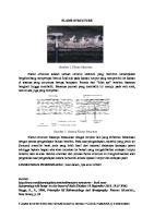
ATTACHMENT-1 Data Sheet for Flame Arresters
General Design
Tag Number
48-FLA-102
48-FLA-103
Qty. (pc(s))
1
1
1
P&ID No.
ARS-R-PI-48-004
ARS-R-PI-48-004
ARS-R-PI-50-032
Line No
2"-VN-50003-1LL
4"-VN-48001-1B
4"-VN-48002-1B
Piping Class
1B
1B
1LL
Design Code
BS EN 12874 / EN ISO 16852 4” Flanged Cl.150 RF ASME B16.5 Vent Tank Flame Arrester, Deflagration type (VTA) Crimped Metal or Vendor's Recommendation End-of-Line , Vertical
BS EN 12874 / EN ISO 16852 4” Flanged Cl.150 RF ASME B16.5 Vent Tank Flame Arrester, Deflagration type (VTA) Crimped Metal or Vendor's Recommendation End-of-Line , Vertical
BS EN 12874 / EN ISO 16852 2” Flanged Cl.150 RF ASME B16.5
Size and Connection Arrestor Type Design & Construction
(note 1,2,5)
Type of Element
(note 2)
Installation Position Gas Group (NEC or IEC) Inlet Pipe Size & C.A Press.
(psig)
Temp. (Min./Max.) Test Press.
(deg.F)
Ambient Temp. (Min / Max) Humidity (Min / Max / Design) Wind Speed
As per BS EN 12874
On-Shore
On-Shore
(deg.F)
(note 6)
70 / 100
70 / 100
70 / 100
(%)
(note 6)
m/s
(note 6)
63.3 / 96.1 / 100 Min : 2 / Max :33.44 / Des :34.87 at 10 meter above grade Air
63.3 / 96.1 / 100 Min : 2 / Max :33.44 / Des :34.87 at 10 meter above grade Air
63.3 / 96.1 / 100 Min : 2 / Max :33.44 / Des :34.87 at 10 meter above grade Hydrocarbon Gas
(psig)
ATM
ATM
ATM
AMB
AMB
AMB
Negligible
Negligible
Negligible
28.90
28.90
21.18
668.52
668.52
275.21
(psi) (lb/hr)
30
30
60
1.00
1.00
1.00
(lb/ft3)
0.07
0.07
0.06
(cP)
0.01
0.01
0.01
Atmosphere
Atmosphere
Atmosphere
Max : 100 deg F Min : 70 deg F Nominal : 47.1 bbl Net working : 31.5 bb W : 7'-8" L : 7'-8" H : 5'-0" VTA
Max : 100 deg F Min : 70 deg F Nominal : 130 bbl Net working : 63 bb W : 7'-8" L : 7'-8" H : 12'-11" VTA
Max : 100 deg F Min : 70 deg F
ASTM A216 Gr. WCB
ASTM A216 Gr. WCB
ASTM A216 Gr. WCB
(ft/sec)
Density Vis. (cP) Ehaust Condition Ambient temperature
(deg.F)
Tank/Vessel Capacity
(Ltr)
Tank/Vessel Dimension
(Ft-Inch)
Distance from Ignition Source
(Ft-Inch)
Housing / Flange
(note 3)
N/A N/A VTA
Element
SS 316
SS 316
SS 316
Gasket
Non Asbestos
Non Asbestos
Non Asbestos
ASTM A193 B7 / A194 2H Hot Dipped Galvanized
ASTM A193 B7 / A194 2H Hot Dipped Galvanized
ASTM A193 B7 / A194 2H Hot Dipped Galvanized
Rain Hood
Manufacturer Std.
Manufacturer Std.
Manufacturer Std.
Other
Manufacturer Std.
Manufacturer Std.
Manufacturer Std.
100% as per MSS SP-55
100% as per MSS SP-55
100% as per MSS SP-55
As per BS EN 12874
As per BS EN 12874
As per BS EN 12874
Body bolt & nut
Visual Examination Pressure Test Sour
(Y:Yes, N:No)
Certification / Approval External Painting Surface preparation Primer Intermediate Top Coat Total DFT Final color Internal Painting
3 4 5 6
ATM -20 / 150
As per BS EN 12874
Z-factor
Notes 1 2
ATM 70 / 140
(deg.F)
Flow Velocity
Remarks
ATM 70 / 140
Temp.
Mass Flow Rate
Other
IIA (D) 2" SCH 80 (3mm C.A)
On-Shore
Mol. Weight
Test & Inspection
IIA (D) 4" SCH 40 (3mm C.A)
Press. Max. Allow. Press. Drop
Parts Material
IIA (D) 4" SCH 40 (3mm C.A)
As per BS EN 12874
Service Fluid
Operating Condition
Deflagration type (VTA) Crimped Metal or Vendor's Recommendation End-of-Line , Vertical
(note 6)
(Inch (mm))
Plant Location
Design Condition
50-FLA-102
N UL / FM / EN / ATEX or Other Equivalent System No. 1 Abrasive Blast to SSPC-SP-10 Inorganic zinc rich primer 3 mils High Solid Epoxy 5 mils Aliphatic polyurethane 2 mils 10 mils
N UL / FM / EN / ATEX or Other Equivalent System No. 1 Abrasive Blast to SSPC-SP-10 Inorganic zinc rich primer 3 mils High Solid Epoxy 5 mils Aliphatic polyurethane 2 mils 10 mils
N UL / FM / EN / ATEX or Other Equivalent System No. 1 Abrasive Blast to SSPC-SP-10 Inorganic zinc rich primer 3 mils High Solid Epoxy 5 mils Aliphatic polyurethane 2 mils 10 mils
Safety Red (OSHA) or Signal red Safety Red (OSHA) or Signal red Safety Red (OSHA) or Signal red 537 (BS 381C: 1980 537 (BS 381C: 1980 537 (BS 381C: 1980 Designation) Designation) Designation) Not Required Oil Catcher A (48-ABH-404)
Not Required
Not Required
Oil Catcher B (48-ABH-405)
Export Gas Metering (50-ZAU-506) (Expected flow rate or maintenance period only)
Flame arresters fabricated from welding flanges and reducers is not allowed. The flame arrester shall be designed to allow for ease of inspection and removal of internal elements for replacements, cleaning or repair without removal of the entire device from the system. The element design shall maximize venting flow capacity with minimum pressure drop Vendor shall specify the limitation of dimensions for installation of the Flame Arresters. Flame arresters supplied shall also be UL listed or FM / EN approved or ATEX certified or other equivalents Vendor to confirm the type of Flame Arrester by calculation. Vendor may offer different type of flame arrester with supporting calculation Environmental condition refer to Specification for Site and Utility Design Data, BLA-M-TS-00-020 (Contractor ID, S-000-1222-006)
CONTRACTOR ID : S-000-1360-211
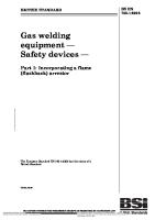
General
Tag Number
37-FLA-105
37-FLA-106
Qty. (pc(s))
1
1
1
ARS-R-PI-37-006
ARS-R-PI-37-006
ARS-R-PI-37-006
P&ID No. Desi gn
Line No
2"-VN-
2"-VN-37015-1B
1
37014-1B
1B 1B
1B
BS EN 12874 / EN ISO 16852
BS EN 12874 / EN ISO 16852
2”
Size and Connection
2” Flanged Cl.150 RF ASME B16.5
F l a n g e d
1
2"-VN-37016-1B
1
Piping Class Design Code 12874 / EN ISO 16852
37-FLA-107
BS EN
2” Flanged Cl.150 RF ASME B16.5
C l . 1 5 0 R F A S M E B 1 6 . 5 Arrestor Type Design & Constructi on
(note 1,2,5) Deflagration (VTA) Deflagration (VTA)
Type of Element or Vendor's
Crimped Metal
(note 2)
Crimped Metal or Vendor's Recommendat ion
Recommendation Installation Position
Deflagration (VTA)
Inline, Vertical
Crimped Metal or Vendor's Recommend ation Inline, Vertical
Inline, Vertical Gas Group (NEC or IEC) IIA (D)
IIA (D)
IIA (D) Inlet/Outlet Pipe Size & C.A 2" SCH 80 (3mm C.A)
2" SCH 80 (3mm C.A)
(psig) Design Conditi on
2" SCH 80 (3mm C.A) Press.
ATM
ATM
ATM Temp. (Min./Max.) 170 Test Press. EN 12874
(deg.F)
70 / 170
70 / 170
As per BS EN 12874
As per BS EN 12874
(note 6)
On-Shore
On-Shore
(deg.F)
(note 6)
70 / 100
70 / 100
(%)
(note 6)
63.3 / 96.1 / 100
63.3 / 96.1 / 100
(Inch (mm))
Plant Location Shore Ambient Temp. (Min / Max) 100 Humidity (Min / Max / Design) 96.1 / 100 Wind Speed
m/s
(note 6) Service Fluid Press.
Min : 2 / Max : 33.44 / Des :34.87 at 10 meter above grade Air Air
(psig) ATM Temp.
ATM
ATM AMB
AMB Max. Allow. Press. Drop
Weight
On70 /
Air
Negligible
(psi) Negligible Mol.
28.90
28.90
(lb/hr) 89.65
89.65
89.65
(ft/sec) 14.76
14.76
14.76
1.00 1.00
1.00
(lb/ft3) 0.02
0.02
0.02
(cP) 0.01
0.01
0.01
Atmosphere Atmosphere
Atmosphere
28.90 Operati ng Conditi on
Mass Flow Rate Flow Velocity Z-factor Density Vis. (cP) Ehaust Condition (deg.F) F
Tank/Vessel Capacity
Max : 100 deg F
(Ltr) N/A
Min : 70 deg
Max : 100 deg F Min : 70 deg F N/A
As per BS
Min : 2 / Max : 33.44 / Des :34.87 at 10 meter above grade
(deg.F)
AMB Negligible
Min : 2 / Max : 33.44 / Des :34.87 at 10 meter above grade
70 /
Max : 100 deg F Min : 70 deg F N/A
63.3 /
Tank/Vesacturer sel Std. Dimensi Other on (Ft-Inch) Manufa N/A cturer N/A N/A Std.
Manufacturer Std.
Pressure Test EN 12874 Sour
As per BS EN 12874
As per BS EN 12874
N
N
(Y:Yes, N:No) N
Certification / Approval FM / EN / ATEX or
External Painting
UL / FM / EN / ATEX UL / FM / EN / or ATEX or Other Other Other Equivalent Equivalent Equivalent System No. 1 System No. 1 System No. 1
Abrasive Blast to Ot her
Primer zinc rich primer
SSPC-SP-10 Inorganic 3 mils High
Intermediate Solid Epoxy Top Coat polyurethane
5 mils Aliphatic 2 mils
Gasket Non Asbestos Non Asbestos
Total DFT
Non Asbestos
bolt & nut ASTM A193 B7 / A194 2H Hot D i p p e d G a l v a n i z e d
Rai n Test Ho od Inspecti on Ma nuf act ure r Std . Ma nuf act ure r Std . Ma nuf
A S T M
A S T M
A 1 9 3
A 1 9 3
B B 7 7 / A 1 9 4
/ A 1 9 4
2 H 2 H H o H t o t Dipp ed Dip Gal ped vani Gal zed vani zed
Final color
Internal Painting Required R e m ar ks
3 4 5 6
Abrasive Blast to SSPCSP-10 Inorganic zinc rich primer 3 mi ls High Solid Epoxy 5 mi ls Aliphatic polyurethane 2 mi ls
Abrasive Blast to SSPCSP-10 Inorganic zinc rich primer 3 m il s High Solid Epoxy 5 m il s Aliphatic polyurethane 2 m il s 10 mils
10 mils 10 mils Safety Red (OSHA) or Signal red Safety Red (OSHA) or Signal red Safety Red (OSHA) or Signal red 537 (BS 381C: 1980 Desig nation ) Not Required
Condensate truck venting truck venting
Notes 1 2
As per BS
UL /
Surface preparation
Element SS 316 SS 316 SS 316
Parts Body Material
100% as per MSS SP-55
100% as per MSS SP-55
Distance from Ignition Source (Ft-Inch) (note VTA VTA VTA Housing / Flange ASTM A216 WCB ASTM A216 WCB ASTM A216 WCB
Manufacturer Std. Visual Examination 100% as per MSS SP-55
537 (BS 381C: 1980 Designati on)
537 (BS 381C: 1980 Designa tion) Not Required
Condensate truck venting
Not
Condensate
Flame arresters fabricated from welding flanges and reducers is not allowed. The flame arrester shall be designed to allow for ease of inspection and removal of internal elements for replacements, cleaning or repair without removal of the entire device from the system. The element design shall maximize venting flow capacity with minimum pressure drop Vendor shall specify the limitation of dimensions for installation of the Flame Arresters. Flame arresters supplied shall also be UL listed or FM / EN approved or ATEX certified or other equivalents Vendor to confirm the type of Flame Arrester by calculation. Vendor may offer different type of flame arrester with supporting calculation Environmental condition refer to Specification for Site and Utility Design Data, BLA-M-TS-00-020 (Contractor ID, S-000-1222-006)
General
Tag Number
37-FLA-108
Qty. (pc(s))
1
1
ARS-R-PI-37-007
ARS-R-PI-37-007
P&ID No. Desi gn
37-FLA-109
Line No
2"-VN-
2"-VN-37018-1B
1
37017-1B
1
Piping Class
1B
1B
Design Code
BS EN 12874 / EN ISO 16852
BS EN 12874 / EN ISO 16852
2”
Size and Connection
2” Flanged Cl.150 RF ASME B16.5
F l a n g e d C l . 1 5 0 R F A S M E B 1 6 . 5
Arrestor Type Design & Constructi on
(note 1,2,5)
Type of Element or Vendor's
Deflagration (VTA) Crimped Metal
(note 2)
Crimped Metal or Vendor's Recomm endation
Recommendation Installation Position
Deflagration (VTA)
Inline, Vertical Inline, Vertical Gas Group (NEC
or IEC)
IIA (D) IIA (D) Inlet/Outlet Pipe Size
& C.A
2" SCH 80 (3mm C.A) 2" SCH 80 (3mm C.A) Press.
Design Conditi on
(psig) ATM ATM
Temp. (Min./Max.) Test Press.
(deg.F) (Inch (mm))
Plant Location Ambient Temp. (Min / Max) Humidity (Min / Max / Design)
70 / 170 As per BS EN 12874 On-Shore
(note 6)
On-Shore
(deg.F)
(note 6)
70 / 100
70 / 100
(%)
(note 6)
63.3 / 96.1 / 100
63.3 / 96.1 / 100
Wind Speed
m/s
(note 6) Service Fluid Press.
70 / 170 As per BS EN 12874
Min : 2 / Max : 33.44 / Des :34.87 at 10 meter above grade Air
(psig)
Min : 2 / Max :33.44 / Des :34.87 at 10 meter above grade Air
ATM
ATM Temp.
(deg.F)
AMB AMB Max. Allow. Press. Drop (psi)
Negligible
Negligible Mol. Weight 28.90 Operati ng Conditi on
28.90 Mass Flow Rate Flow Velocity
(lb/hr)
89.65
89.65
(ft/sec)
14.76
14.76
1.00
1.00
(lb/ft3)
0.02
0.02
(cP)
0.01
0.01
Atmosphere
Atmosphere
Z-factor Density Vis. (cP) Ehaust Condition (deg.F) F
Tank/Vessel Capacity
Min : 70 deg
Max : 100 deg F Min : 70 deg F
(Ltr)
N/A
N/A
Tank/Vessel Dimension
(Ft-Inch)
N/A
N/A
Distance from Ignition Source
(Ft-Inch)
Housing / Flange Element Parts
Max : 100 deg F
Gasket Material
(note 3)
VTA
VTA
ASTM A216 Gr. WCB
ASTM A216 Gr. WCB
SS 316
SS 316
Non Asbestos
Non Asbestos
a l v o a n dy i z b e d ol
S
A S T M
B
&
Examination
ut
100% as per MSS SP-55 Pressure Test Sour
O
External Painting
A 1 9 4
S T M A 3 7/
Primer zinc rich primer
19 4 2 H
UL / FM / EN / ATEX or Other Other Equivalent Equival ent System No. 1
3 mils
Top Coat polyurethane
High 5 mils Aliphatic
ot D i p p e d G
m i l s High Solid Epoxy 5
2 mils
G a l v a n i z e d
H
System No. 1
Abrasiv e Blast to SSP CSP10 Inorganic zinc rich primer 3
SSPC-SP-10 Inorganic
Intermediate Solid Epoxy D i p p e d
A
N
UL /
Abrasive Blast to Ot her
H o t
B
As per BS EN 12874
N
Surface preparation
2 H
19
As per BS EN 12874 (Y:Yes, N:No)
Certification / Approval FM / EN / ATEX or
/
A
100% as per MSS SP-55
.
B 7
n
Manufacturer Std. Manufacturer Std. Visual
d
A 1 9 3
t
ther
t
m i l s Aliphatic polyurethane 2
R
m i l s
a Test i n Inspecti on
Total DFT
H
Final color
o o d Internal Painting
10 mils 10 mils Safety Red (OSHA) or Signal red Safety Red (OSHA) or Signal red 537 (BS 381C: 1980 Desig nation ) Not Required
537 (BS 381C: 1980 De sig nati on) Not Required
M a n u f
R e m ar ks
Condensate truck venting
Condensate truck venting
a c t u
Notes 1 2
r e r S t d .
M a n u f a c t u r e r
3 4 5 6
Flame arresters fabricated from welding flanges and reducers is not allowed. The flame arrester shall be designed to allow for ease of inspection and removal of internal elements for replacements, cleaning or repair without removal of the entire device from the system. The element design shall maximize venting flow capacity with minimum pressure drop Vendor shall specify the limitation of dimensions for installation of the Flame Arresters. Flame arresters supplied shall also be UL listed or FM / EN approved or ATEX certified or other equivalents Vendor to confirm the type of Flame Arrester by calculation. Vendor may offer different type of flame arrester with supporting calculation Environmental condition refer to Specification for Site and Utility Design Data, BLA-M-TS-00-020 (Contractor ID, S-000-1222-006)
BLOCK-A GAS DEVELOPMENT PROJECT TECHNICAL SPECIFICATION FOR FLAME ARRESTERS
Doc. No:
BLA-P-TS-00-211 Rev. 1 Date :
Page : 13 of 17 20-MAY-16
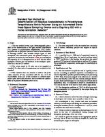
ATTACHMENT – 2 P&ID REFERENCES
CONTRACTOR ID: S-000-1360-211
13 14 16 15
I1 1
1 4
I
I
I
8
1
9
I
JOB CONTRAC CODE TOR ID. D0709-00048-12250000 104
I
I
10
I
I
I
48-ABH-404 I
ITEM SERVICE
A
T"PE llMf NSIIm (Wxl xll) C'IPACIH
:tt)
(rl 3
TE IF. ('F) UcSIG I. 1 ----c----"loS ( sig) OPER. INSUlATIUN MA ERA_
S E RECTANGULA;; FLATTTANK Y 7' -8''W X 7' -S"L lX -O"J l C A 70/1 LQ T --+---'------------E U FULL OF WATER c OIL CATC ICR A
TE IF.
I
('F)
=·
AMB.
1
ATM. T -liiX
ONe CONCRETE)
R l S T E
13 14 16 15
I1 1
= 0
OPER.
PRESS (Psig) .AW.
B
P
co
5 24"
r U r
n
I
H
O F O I F U W I
-
I
MATERIAL
B
4 -
FIREWATEC:: PLMP
W0-45DD 1 PI-45CJCJ?
/ o \
E
N O T E
2
WD-13-006
W0-13-0C3
Pl-43-004
PI-43-0J2
I
D 1'1./ ;, +------+--+------------------+--------------
13 14 16 15
I1 1
es1 hm iiN Fw r
-
D
3 .
7
H N
L
L
1
C_
In \ V
S C
4
OIL CATCHER
1c_I
2
I I I I
7
I
1
4 11
12 JOB
I
I
8
CODE 0-0709-00-0000 I
CONTRACTOR ID. D-050-
I
9
1225-132
A A
I
ITEMITEM
SERVJ:E SERV CE
I
50-ZAU-506 50-ZAU-507 EXPORT EXPORT GASGAS HETERI ANALYZER JG
-
50-ZAU--- Oc-·-I OTE I' 2
I B
I \
M
50I
\
I--
b
I
I
0
I
-
n
T O
I I
0 I
: I f-------f-------.---t------ l_j -
N O T E 1 3
,o-o-c-o-c-o-o-o-o-o-o-o-o-o-o-o-o-o-o-o-o-o-u-cu-o-r-o-o-u-u-o-f-o-o
1
o
I
n
o
I I 1
I
0
I I
I I I I
o '
I \
0